gs20-gs21-gs30 series
TRANSCRIPT

Lowara
GS20-GS21-GS30Series
Fixed-speed pressure booster sets withVertical Multistage electric pumps e-SV™series
50 Hz50 Hz50 Hz50 Hz50 Hz

2
Lowara
WEB 10-2010
General introduction .............................................................................................................................33333
Choice and selection .............................................................................................................................44444
GS.../SV GS.../SV GS.../SV GS.../SV GS.../SV Series ................................................................................................................................1111111111
Range ...............................................................................................................................................1313131313
Characteristics of the electric pumps .............................................................................................1414141414
Hydraulic performance tables ...........................................................................................................1919191919
Electric data tables............................................................................................................................2525252525
GSD20 - GSY20 Series .....................................................................................................................2727272727
GSD21 - GSY21 Series ......................................................................................................................4141414141
GSD30 - GSY30 Series ......................................................................................................................5151515151
Operating characteristics at 50 Hz ...................................................................................................6262626262
Hc pressure drop curve ....................................................................................................................8585858585
Accessories ......................................................................................................................................8989898989
Technical Appendix ..........................................................................................................................9393939393
CONTENTSCONTENTSCONTENTSCONTENTSCONTENTS

3
LowaraBOOSTER SETS GS SERIESBOOSTER SETS GS SERIESBOOSTER SETS GS SERIESBOOSTER SETS GS SERIESBOOSTER SETS GS SERIESGENERAL INTRODUCTION - PRODUCT DESCRIPTIONGENERAL INTRODUCTION - PRODUCT DESCRIPTIONGENERAL INTRODUCTION - PRODUCT DESCRIPTIONGENERAL INTRODUCTION - PRODUCT DESCRIPTIONGENERAL INTRODUCTION - PRODUCT DESCRIPTIONThe GS series pressure booster units mainly comprise pumping stations assembled with two or three SV series verticalmultistage pumps, or with FH or SH series enbloc horizontal pumps. A smaller pump can also be added to the mainones. Generally known as a jockey pump, it provides for minor usages in order to maintain system pressure withoutstarting the service pump.The GS series pressure booster units are constant speed sets and are used to distribute water in heating or fillingsystems.The pumps are mounted on a single base together with the other hydraulic components, such as on-off valves, checkvalves and the delivery and return manifolds.The electrical panel, supplied with a mounting bracket, is attached to the pressure booster unit base.The pumps start and stop according to the signals sent by the pressure transducer to the electrical control panel.The latter is fitted with an integrated electronic board. The pumps start and stop automatically depending on thewater demand of the system.These pressure booster systems are combined with suitable expansion tanks in order to guarantee stable operationand reduce the starting frequency of the pumps.For the correct choice in capacity of the expansion vessel, see the relative chapter on page 102 of the catalogue.
DESCRIPTION OF OPERADESCRIPTION OF OPERADESCRIPTION OF OPERADESCRIPTION OF OPERADESCRIPTION OF OPERATIONTIONTIONTIONTIONThe pumps start and stop according to the set pressures detected by the pressure transducer, thus ensuring therequired amount of water is delivered. The pressure values can be directly set on the electronic board.For units with jockey pump, the latter will start first and stop last, depending on the set pressure values.When a tap is opened, water is drawn off from the tank, the pressure starts to fall until it reaches the starting valueof the first pump. The delivery of water increases, the pressure falls even further and the other pumps start insequence according to the demand for water.When consumption falls, the pressure in the system increases and the pumps stop when the set threshold pressurevalues are reached.If consumption falls to zero user demand, the last pump also stops.If the “timer” function is used, the last pump to work will remain operating for a set time after it is switched off, inorder to reach maximum pressure. Make sure the maximum pressure is compatible with the system in which thepump is installed.
Example: GS series pressure booster units, operation.
∆p pressure differential between pumps, can be reduced to 0,5 bar.
Q
H
Pump 1 Pump 2 Pump 3
P1
P2
P3
P1
P2
P3
Start
Stop
p

4
LowaraBOOSTER SETS GS SERIESBOOSTER SETS GS SERIESBOOSTER SETS GS SERIESBOOSTER SETS GS SERIESBOOSTER SETS GS SERIESCHOICE AND SELECTIONCHOICE AND SELECTIONCHOICE AND SELECTIONCHOICE AND SELECTIONCHOICE AND SELECTIONThe demand of a water distribution system is generally determined by the designer according to the type of userstructure being served.Users can be schools, hospitals, homes, offices, industries, hotels, shopping centres and for each the water demandchanges due to the different requirements of the people living and working in these structures. To find the correctflow rate for the system in question, it is possible to consult pre-calculated tables that give an idea of the flow rate forthe typology of user to serve (see pages 94-95 in this catalogue).Integral system calculation, instead, prevents excessive oversizing and therefore reduces running and installationcosts.The theoretical water demand is calculated by summing the demand of each user. As, however, it is improbable thatall users will want to use water at the same time, real demand is lower than theoretical demand.After defining the flow rate of the system, the head must be calculated. This must consider the following:- geodesic head: difference in level between the pumping station and the highest user- residual head: pressure demand from the most unfavourable user to serve- pressure drops: value in metres of pressure drops due to friction in the delivery pipes- inlet height: difference in level between the pump inlet and the surface of the water in the tank (positive or negative depending on the installation type)- inlet pressure drops: value in metres of pressure drops due to friction in the inlet piping and in any curves and valves. After analysing the above, the head required for the system is calculated.
Now that the flow rate and head values are known, the most suitable pressure booster unit for the system can bechosen. The designer must decide whether to choose a pressure booster unit with two or three pumps, the thirdbeing a reserve pump satisfying demand during pump maintenance periods.
The GS series of pressure booster units must be installed in areas protected from frost and adequately ventilated inorder to allow the motors to cool. The delivery and intake pipes should be connected using anti-vibration joints inorder to limit vibrations and resonance in the system.
INSTINSTINSTINSTINSTALLAALLAALLAALLAALLATIONTIONTIONTIONTION

5
Lowara
The GS series of pressure booster units are generally connected to pressurised tanks with a suitable capacity for thesystem. These tanks are normally expansion vessels for capacities up to 500 L. Tanks with higher capacities can also besupplied if necessary. In these cases, they are air-cushion tanks and a compressor is required to maintain the pressureinside the tank.In both cases, the tanks must be connected on the pressure booster unit delivery line. The system, commonly knownas an “autoclave”, provides the system with a reserve of pressurised water and prevents frequent pump start-ups.
For these systems, sufficient space must always be allowed in the area where the pressure booster set is installed.
Always check maximum pump pressure in order to choose the right tanks for the pressure in question.
SUCTION CONDITIONSSUCTION CONDITIONSSUCTION CONDITIONSSUCTION CONDITIONSSUCTION CONDITIONSInstallation of the pressure booster set must be assessed especially as regards intake conditions. Intake conditions cannegatively or positively affect the performance of the pressure booster unit and consequently system performance.A positive suction head is ideal for a pressure booster unit as it keeps the pumps constantly primed and the positivedifference in level adds pressure to the system.A negative suction head is different. In this case, the risks for the pumps are priming which is connected with theintake piping, the NPSH of the pump and the difference in level between the pump and the water in the tank.In this type of installation, after checking the intake capacity of the pump, the overall pressure drop in the intake linemust be calculated as this will reduce pump performance and consequently that of the pressure booster unit.In order to select the right pressure booster unit, the performance levels of the pumps installed on them are indicatedin this catalogue. To simplify the calculation of net pressure, pressure drop curves, both for the delivery and intakelines of the pumps have been included (see the relative chapter).
BOOSTER SETS GS SERIESBOOSTER SETS GS SERIESBOOSTER SETS GS SERIESBOOSTER SETS GS SERIESBOOSTER SETS GS SERIESINSTINSTINSTINSTINSTALLAALLAALLAALLAALLATIONTIONTIONTIONTION
6
Lowara
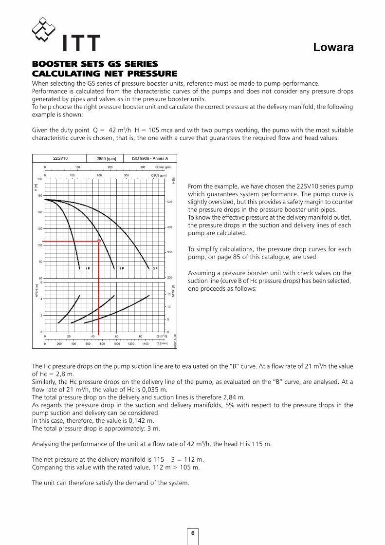
When selecting the GS series of pressure booster units, reference must be made to pump performance.Performance is calculated from the characteristic curves of the pumps and does not consider any pressure dropsgenerated by pipes and valves as in the pressure booster units.To help choose the right pressure booster unit and calculate the correct pressure at the delivery manifold, the followingexample is shown:
Given the duty point Q = 42 m3/h H = 105 mca and with two pumps working, the pump with the most suitablecharacteristic curve is chosen, that is, the one with a curve that guarantees the required flow and head values.
From the example, we have chosen the 22SV10 series pumpwhich guarantees system performance. The pump curve isslightly oversized, but this provides a safety margin to counterthe pressure drops in the pressure booster unit pipes.To know the effective pressure at the delivery manifold outlet,the pressure drops in the suction and delivery lines of eachpump are calculated.
To simplify calculations, the pressure drop curves for eachpump, on page 85 of this catalogue, are used.
Assuming a pressure booster unit with check valves on thesuction line (curve B of Hc pressure drops) has been selected,one proceeds as follows:
The Hc pressure drops on the pump suction line are to evaluated on the “B” curve. At a flow rate of 21 m3/h the valueof Hc = 2,8 m.Similarly, the Hc pressure drops on the delivery line of the pump, as evaluated on the “B” curve, are analysed. At aflow rate of 21 m3/h, the value of Hc is 0,035 m.The total pressure drop on the delivery and suction lines is therefore 2,84 m.As regards the pressure drop in the suction and delivery manifolds, 5% with respect to the pressure drops in thepump suction and delivery can be considered.In this case, therefore, the value is 0,142 m.The total pressure drop is approximately: 3 m.
Analysing the performance of the unit at a flow rate of 42 m3/h, the head H is 115 m.
The net pressure at the delivery manifold is 115 – 3 = 112 m.Comparing this value with the rated value, 112 m > 105 m.
The unit can therefore satisfy the demand of the system.
BOOSTER SETS GS SERIESBOOSTER SETS GS SERIESBOOSTER SETS GS SERIESBOOSTER SETS GS SERIESBOOSTER SETS GS SERIESCALCULACALCULACALCULACALCULACALCULATING NET PRESTING NET PRESTING NET PRESTING NET PRESTING NET PRESSURESURESURESURESURE
H [m
]
60
80
100
120
140
160
1800 100 200 300 400
H [f
t]
200
300
400
500
0 100 200 300
0 20 40 60 80 100
NP
SH
[m]
0
2
4
6
0 200 400 600 800 1000 1200 1400 1600
NP
SH
[ft]
0
5
10
15
7684
2_A
_CH
22SV10 ∼ 2850 [rpm] ISO 9906 - Annex A
1 P 2 P 3 P
Q [Imp gpm]
Q [US gpm]
Q [m3/h]
Q [l/min]
7
Lowara
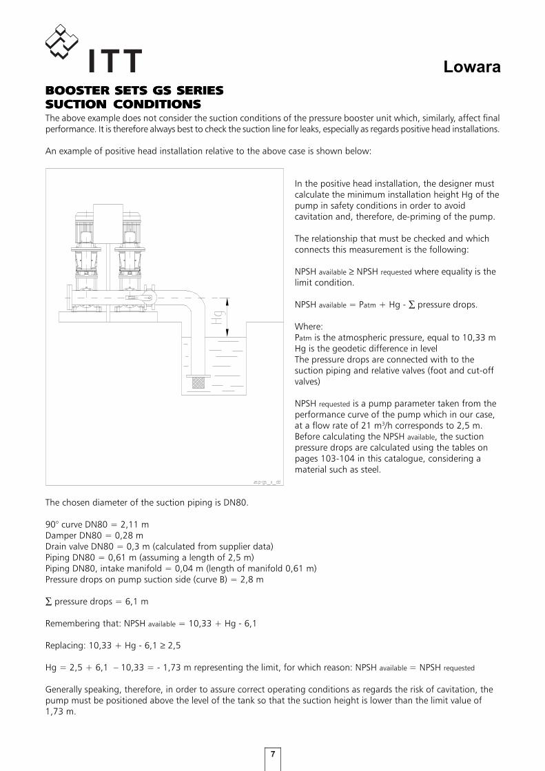
The above example does not consider the suction conditions of the pressure booster unit which, similarly, affect finalperformance. It is therefore always best to check the suction line for leaks, especially as regards positive head installations.
An example of positive head installation relative to the above case is shown below:
In the positive head installation, the designer mustcalculate the minimum installation height Hg of thepump in safety conditions in order to avoidcavitation and, therefore, de-priming of the pump.
The relationship that must be checked and whichconnects this measurement is the following:
NPSH available ≥ NPSH requested where equality is thelimit condition.
NPSH available = Patm + Hg - ∑ pressure drops.
Where:Patm is the atmospheric pressure, equal to 10,33 mHg is the geodetic difference in levelThe pressure drops are connected with to thesuction piping and relative valves (foot and cut-offvalves)
NPSH requested is a pump parameter taken from theperformance curve of the pump which in our case,at a flow rate of 21 m3/h corresponds to 2,5 m.Before calculating the NPSH available, the suctionpressure drops are calculated using the tables onpages 103-104 in this catalogue, considering amaterial such as steel.
The chosen diameter of the suction piping is DN80.
90° curve DN80 = 2,11 mDamper DN80 = 0,28 mDrain valve DN80 = 0,3 m (calculated from supplier data)Piping DN80 = 0,61 m (assuming a length of 2,5 m)Piping DN80, intake manifold = 0,04 m (length of manifold 0,61 m)Pressure drops on pump suction side (curve B) = 2,8 m
∑ pressure drops = 6,1 m
Remembering that: NPSH available = 10,33 + Hg - 6,1
Replacing: 10,33 + Hg - 6,1 ≥ 2,5
Hg = 2,5 + 6,1 – 10,33 = - 1,73 m representing the limit, for which reason: NPSH available = NPSH requested
Generally speaking, therefore, in order to assure correct operating conditions as regards the risk of cavitation, thepump must be positioned above the level of the tank so that the suction height is lower than the limit value of1,73 m.
BOOSTER SETS GS SERIESBOOSTER SETS GS SERIESBOOSTER SETS GS SERIESBOOSTER SETS GS SERIESBOOSTER SETS GS SERIESSUCTION CONDITIONSSUCTION CONDITIONSSUCTION CONDITIONSSUCTION CONDITIONSSUCTION CONDITIONS
8
LowaraSET IDENTIFICASET IDENTIFICASET IDENTIFICASET IDENTIFICASET IDENTIFICATION CODETION CODETION CODETION CODETION CODE
GS
SPECIAL VERSIONSSPECIAL VERSIONSSPECIAL VERSIONSSPECIAL VERSIONSSPECIAL VERSIONSSpecial versions for materials, operating temperature, control panels with additional functions availableon request.
OPTIONS (ON DEMAND)OPTIONS (ON DEMAND)OPTIONS (ON DEMAND)OPTIONS (ON DEMAND)OPTIONS (ON DEMAND)
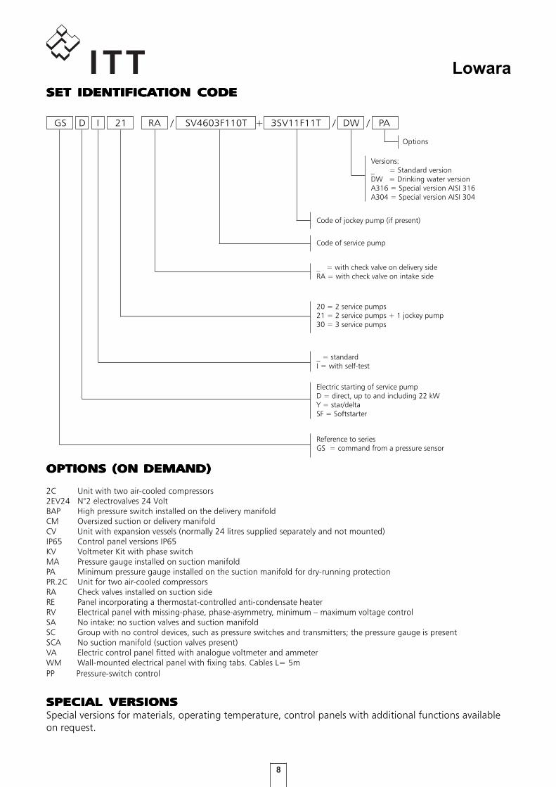
2C Unit with two air-cooled compressors2EV24 N°2 electrovalves 24 VoltBAP High pressure switch installed on the delivery manifoldCM Oversized suction or delivery manifoldCV Unit with expansion vessels (normally 24 litres supplied separately and not mounted)IP65 Control panel versions IP65KV Voltmeter Kit with phase switchMA Pressure gauge installed on suction manifoldPA Minimum pressure gauge installed on the suction manifold for dry-running protectionPR.2C Unit for two air-cooled compressorsRA Check valves installed on suction sideRE Panel incorporating a thermostat-controlled anti-condensate heaterRV Electrical panel with missing-phase, phase-asymmetry, minimum – maximum voltage controlSA No intake: no suction valves and suction manifoldSC Group with no control devices, such as pressure switches and transmitters; the pressure gauge is presentSCA No suction manifold (suction valves present)VA Electric control panel fitted with analogue voltmeter and ammeterWM Wall-mounted electrical panel with fixing tabs. Cables L= 5mPP Pressure-switch control
D I 21 RA / SV4603F110T 3SV11F11T+ DW / PA/
Versions:_ = Standard versionDW = Drinking water versionA316 = Special version AISI 316A304 = Special version AISI 304
Code of jockey pump (if present)
Code of service pump
_ = with check valve on delivery sideRA = with check valve on intake side
20 = 2 service pumps21 = 2 service pumps + 1 jockey pump30 = 3 service pumps
_ = standardI = with self-test
Electric starting of service pumpD = direct, up to and including 22 kWY = star/deltaSF = Softstarter
Reference to seriesGS = command from a pressure sensor
Options

9
LowaraCONTROL PCONTROL PCONTROL PCONTROL PCONTROL PANEL FOR GS20, GS21, GS30ANEL FOR GS20, GS21, GS30ANEL FOR GS20, GS21, GS30ANEL FOR GS20, GS21, GS30ANEL FOR GS20, GS21, GS30
GS
Electric panelElectric panelElectric panelElectric panelElectric panel for powering, controlling and protecting amaximum of three three-phase pumps, with sheet steel casing(fig. 1) and protected to IP55.
Main characteristics:
- General doorlock switch, fuse holders and fuses, starting contactors and circuit breakers.- Standard input voltage: 3x400Vca +/-10%, 50/60Hz. Non-standard voltages available on request, 1x230Vac +/-10%, 3x230ca +/-10%, 50/60Hz.- Transformer for auxiliary low voltage circuit; auxiliary voltage 24Vac.- Lowara SM30 digital microprocessor-controlled control unit with LCD display and programming keyboard (see fig. 2), featuring the following functions:
• Indicator lamps: power on (ref.1), general fault (ref.2), no water alarm (ref.3), pump running (ref.4);• Programming keyboard (ref.5);• Manual pump stop/start (one button for each pump) (ref.5);• Automatic cascade pump control with two electronic pressure transmitters. If a sensor develops a fault, the board automatically switches to the second sensor. Pressure switch control available on request.• Jockey pump management.• Cycle reversal function (can be disabled). Automatically switches pumps after every start/stop cycle.• Automatic, manual or disabled mode switches for each pump (inside the board).• Periodic system self-test with an electrovalve command which opens the hydraulic circuit, simulates a pressure drop and consequently activates the control devices (pressure switches and pressure transmitters). Pump diagnostics.
• No-water protection system alternatives: float, minimum pressure switch, external contact or electrode probes with sensitivity adjustment.• Adjustable timer delaying tripping the no-water protection system.• Adjustable timer delaying starting of each pump.• Adjustable timer extending the operation of each pump.• System pressure drop offset function, only available with pressure sensor. This function improves system stability.• Adjustable analogue output, 4-20mA or 0-10Vdc, for visualising the analogue input signal.• Configurable relay with volt-free contact, delayed activation, signalling the following conditions: - Motor overload protection alarm. - No-water circuit alarm. - Pressure sensor fault. - Out-of-curve operation alarms (only if self-test is disabled). - Maximum intake pressure alarm. - Electrovalve opening permission for self-test circuit.• Configurable digital inputs. - AUX1 input configuration, maximum pressure switch or external self-test. - AUX2 input configuration, permission from external device (NO) or external alarm (NC). - AUX3 input configuration, change set (NO) or pressure switch operating out-of-curve.• 12Vdc output for powering the acoustic alarm.
fig. 1
1
2
3
5
4
fig. 2
10
LowaraCONTROL PCONTROL PCONTROL PCONTROL PCONTROL PANEL FOR GS20, GS21, GS30ANEL FOR GS20, GS21, GS30ANEL FOR GS20, GS21, GS30ANEL FOR GS20, GS21, GS30ANEL FOR GS20, GS21, GS30
• Alarms log and hour counters for each installed pump. Alarms visualised on display: - Maximum, minimum pressure; - Circuit breaker for each motor; - Pressure transmitter fault. - Out-of-curve operation; - No water; - Block for tripped external device (PTC, temperature probe, etc.) - Auto-test failed All the alarms light the Fault lamp (ref.2 – fig.2) The no-water alarm lights the Level alarm lamp (ref.3 – fig.2)• Standard, RS485 serial communication, slave, and ModBus RTU protocol.• The GSM/GPRS module can be connected to send pump alarms and/or operating states via sms or e-mail. Connection via RS485 serial connection. SIM card not included.• A relay board (optional) can be connected to boost the following signals: pump running, aut-man mode for each pump, overload alarm, no-water alarm, maximum/minimum pressure alarm, power on, self-test failed. The optional signal booster board has six relays, each of which can be configured using the Lowara SM30 control unit.
REFERENCE STREFERENCE STREFERENCE STREFERENCE STREFERENCE STANDARDSANDARDSANDARDSANDARDSANDARDS
• The Lowara pressure booster sets are CE-marked for conformity with the following directives: - Machinery Directive: 2006/42/EC. - Low Voltage Directive 2006/95/EC. - Electromagnetic Compatibility Directive 2004/108/EC.
• Electric pump performance complies with the following standard:
ISO 9906-A Rotodynamic pumps – hydraulic performance acceptance tests.

11
Lowara
GS
.../
SV
GS
.../
SV
GS
.../
SV
GS
.../
SV
GS
.../
SV
GS.../SV Series
50 Hz50 Hz50 Hz50 Hz50 Hz
Fixed-speed pressure booster setsVertical Multistage electric pumps e-SV™seriesequipped with high efficiency PLM motorsflow rate up to 360 m3/h

12
LowaraGS.../SV SERIESGS.../SV SERIESGS.../SV SERIESGS.../SV SERIESGS.../SV SERIESHYDRAHYDRAHYDRAHYDRAHYDRAULIC PERFORMANCE RANGE AULIC PERFORMANCE RANGE AULIC PERFORMANCE RANGE AULIC PERFORMANCE RANGE AULIC PERFORMANCE RANGE AT 50 HzT 50 HzT 50 HzT 50 HzT 50 Hz
GS
.../
SV
GS
.../
SV
GS
.../
SV
GS
.../
SV
GS
.../
SV
5 6 7 8 20 30 40 50 60 70 80 20010 100
H [m
]
4
5
6
789
20
30
40
50
60
708090
200
10
100
40 60 80 200 400 600 800100
H [f
t]
20
30
40
50
60
7080
200
300
400
500
600
100
200 400 600 800 2000100 1000
20 40 60 80 200 400 600100
7692
9_A
_CH
Q [l/min]
Q [m3/h]
Q [US gpm]
Q [Imp gpm]
GS.../SVGS.../SVGS.../SVGS.../SVGS.../SV

13
Lowara
GS
.../
SV
GS
.../
SV
GS
.../
SV
GS
.../
SV
GS
.../
SV
RANGERANGERANGERANGERANGE
GS20 SETSGS20 SETSGS20 SETSGS20 SETSGS20 SETS• Fixed-speed sets with two multistage vertical service pumps, SV series, with power ratings up to 37 kW.
GS21 SETSGS21 SETSGS21 SETSGS21 SETSGS21 SETS• Fixed-speed sets with two service pumps and a jockey pump. Multistage vertical electric pumps, SV series, with power ratings up to 37 kW.
GS30 SETSGS30 SETSGS30 SETSGS30 SETSGS30 SETS• Fixed-speed sets with three multistage vertical service pumps, SV series, with power ratings up to 37 kW.
The GS series of fixed-speed pressure boosters comprises models with 2 or 3 electric service pumps andan optional jockey pump in order to satisfy the specific needs of every application.
Head Head Head Head Head up to 160m.Flow rate Flow rate Flow rate Flow rate Flow rate up to 240 m3/h.
Head Head Head Head Head up to 160m.Flow rate Flow rate Flow rate Flow rate Flow rate up to 360 m3/h.
Head Head Head Head Head up to 160m.Flow rate Flow rate Flow rate Flow rate Flow rate up to 240 m3/h.

14
Lowara
The SV pump is a multistage vertical pump, not self-priming, combined with a normalised standard motor. Thehydraulic part is kept in place between the upper cover and the pump body with tie-rods. The pump body isavailable in different configurations and connection typologies.
CHARACTERISTICCHARACTERISTICCHARACTERISTICCHARACTERISTICCHARACTERISTICS OF THE ELECTRIC PUMPSS OF THE ELECTRIC PUMPSS OF THE ELECTRIC PUMPSS OF THE ELECTRIC PUMPSS OF THE ELECTRIC PUMPS
TTTTTechnical Informationechnical Informationechnical Informationechnical Informationechnical Information:
Flow rates: up to 120 m3/h.Heads: up to 160 m.
Temperature of pumped liquid:- from -30°C to +120°C for 3, 5, 10, 15, 22SV standard version.
- from -30°C to +120°C for SV 33, 46, 66, 92, standard version.
Tested to ISO 9906 annex A.Clockwise direction of rotation lookingat the pump from above (indicatedwith an arrow on the bracket and joint).
Mechanical sealMechanical sealMechanical sealMechanical sealMechanical seal
SV pumps (only for 10, 15, 22SV ≥ of 5,5 kW and SV33,46,66,92) are fitted standard with a balanced mechanicalseal that can be replaced without having to remove the motor from the pump.
MotorMotorMotorMotorMotor
Short circuit squirrel cage motor, totally enclosed, fan-cooled. Lowara motors up to 7.5 kW (inclusive) for the 4-poleversion and up to 22 kW (inclusive) for the 2-pole version supplied standard. Other motor brands for higher powers.The performance levels of Lowara PLM surface motors lie within what is usually referred to as efficiency class 1.Protection class IP55.Insulation class F.Performance levels according to EN 60034-1.Standard voltage:Single-phase version: 220-240 Vac, 50 Hz.Three-phase version: 220-240/380-415 Vac, 50 Hz for power ratings up to 3 kW,380-415/660-690 Vac, 50 Hz for power ratings higher than 3 kW.
MaterialsMaterialsMaterialsMaterialsMaterials
Suitable for pumping drinking water (WRAS certified).
GS
.../
SV
GS
.../
SV
GS
.../
SV
GS
.../
SV
GS
.../
SV

15
Lowara
GS
.../
SV
GS
.../
SV
GS
.../
SV
GS
.../
SV
GS
.../
SVCHARACTERISTICCHARACTERISTICCHARACTERISTICCHARACTERISTICCHARACTERISTICS OF 3, 5, 10, 15, 22SV SERIESS OF 3, 5, 10, 15, 22SV SERIESS OF 3, 5, 10, 15, 22SV SERIESS OF 3, 5, 10, 15, 22SV SERIESS OF 3, 5, 10, 15, 22SV SERIES
• Vertical multistage centrifugal pump. All metal parts in contact with the pumped liquid are made of stainless steel.• The following versions are available: - F: round flanges, in-line delivery and suction ports, AISI 304. - T: oval flanges, in-line delivery and suction ports, AISI 304. - R: round flanges, delivery port above the suction port, with four adjustable positions, AISI 304. - N: round flanges, in-line delivery and suction ports, AISI 316. - V: Victaulic® couplings, in-line delivery and suction ports, AISI 316. - C: Clamp couplings (DIN 32676), in-line delivery and suction ports, AISI 316. - K: threaded couplings, (DIN 11851), in-line delivery and suction ports, AISI 316.• Reduced axial thrusts enable the use of standardstandardstandardstandardstandard motors motors motors motors motors that are easly found in the market. reperibili sul mercato. The Lowara SM The Lowara SM The Lowara SM The Lowara SM The Lowara SM ≥≥≥≥≥ 0,75 kW0,75 kW0,75 kW0,75 kW0,75 kW and PLM surface motors have efficiency and PLM surface motors have efficiency and PLM surface motors have efficiency and PLM surface motors have efficiency and PLM surface motors have efficiency values that values that values that values that values that fall within the rangefall within the rangefall within the rangefall within the rangefall within the range normallynormallynormallynormallynormally referred to as referred to as referred to as referred to as referred to as efficiency class IE2efficiency class IE2efficiency class IE2efficiency class IE2efficiency class IE2.• Seal housing chamber designed to prevent the accumulation of air in the critical area next to the mechanical seal.
• Mechanical seal according to EN 12756 (ex DIN 24960) and ISO 3069 for 3, 5SV and 10, 15, 22SV (≤ di 4 kW) series.• Balanced mechanical sealBalanced mechanical sealBalanced mechanical sealBalanced mechanical sealBalanced mechanical seal according to EN 12756 (ex DIN 24960) and ISO 3069, wich cancancancancan be replaced without removing the motorbe replaced without removing the motorbe replaced without removing the motorbe replaced without removing the motorbe replaced without removing the motor from the pumpfrom the pumpfrom the pumpfrom the pumpfrom the pump for 10, 15 and 22SV (≥ di 5,5 kW) series.• Seal housing chamber designed to prevent the accumulation of air in the critical area next to the mechanical seal.• A second plug is available for 10, 15, 22SV series.• Versions with round flanges that can be coupled to counter-flanges, according to EN 1092.• Threaded, oval counter-flanges made of stainless steel are standard supply for the T versions.• Round counter-flanges made of stainless steel are available on request for the F, R and N versions.• Easy maintenance. No special tools required for assembly or disassembly.• Materials are suitable for handlingMaterials are suitable for handlingMaterials are suitable for handlingMaterials are suitable for handlingMaterials are suitable for handling potable water (WRAS and ACpotable water (WRAS and ACpotable water (WRAS and ACpotable water (WRAS and ACpotable water (WRAS and ACS certified)S certified)S certified)S certified)S certified).• Standard version for temperatures ranging from -30°C to +120°C.
CHARACTERISTICCHARACTERISTICCHARACTERISTICCHARACTERISTICCHARACTERISTICS OF SV33, 46, 66, 92 SERIESS OF SV33, 46, 66, 92 SERIESS OF SV33, 46, 66, 92 SERIESS OF SV33, 46, 66, 92 SERIESS OF SV33, 46, 66, 92 SERIES
• Vertical multistage centrifugal pump with impellers, diffusers and outer sleeve made entirely of stainless steel, and with pump casing and motor adaptor made of cast iron in the standard version.• N version made entirely of AISI 316 stainless steel.• High heads and capacities four sizes: SV 33, 46,four sizes: SV 33, 46,four sizes: SV 33, 46,four sizes: SV 33, 46,four sizes: SV 33, 46, 66 and 92 (replacing the previous models 66 and 92 (replacing the previous models 66 and 92 (replacing the previous models 66 and 92 (replacing the previous models 66 and 92 (replacing the previous models SV 30 and 60) SV 30 and 60) SV 30 and 60) SV 30 and 60) SV 30 and 60).• Re-designed liquid end provides improved efficiency and energy savings.• Innovative axial load compensation system on pumps with higher head. This ensures reduced axial thrusts and enables the use of standard motors standard motors standard motors standard motors standard motors that are easly found in the market. The Lowara PLMThe Lowara PLMThe Lowara PLMThe Lowara PLMThe Lowara PLM surface motors have efficiency values that surface motors have efficiency values that surface motors have efficiency values that surface motors have efficiency values that surface motors have efficiency values that fall within the range normally referred to fall within the range normally referred to fall within the range normally referred to fall within the range normally referred to fall within the range normally referred to as efficiency class 1 as efficiency class 1 as efficiency class 1 as efficiency class 1 as efficiency class 1.
• Balanced mechanical sealBalanced mechanical sealBalanced mechanical sealBalanced mechanical sealBalanced mechanical seal according to EN 12756 (ex DIN 24960) and ISO 3069, which cancancancancan be replaced without removing the motorbe replaced without removing the motorbe replaced without removing the motorbe replaced without removing the motorbe replaced without removing the motor from the pumpfrom the pumpfrom the pumpfrom the pumpfrom the pump.• Seal housing chamber designed to prevent the accumulation of air in the critical area next to the mechanical seal.• Materials are suitable for handlingMaterials are suitable for handlingMaterials are suitable for handlingMaterials are suitable for handlingMaterials are suitable for handling potable water (WRAS certified)potable water (WRAS certified)potable water (WRAS certified)potable water (WRAS certified)potable water (WRAS certified).• Standard version for temperatures ranging from -30°C to +120°C.• Pump body fitted with couplings for installing pressure gauges on both suction and delivery flanges.• In-line ports with round flanges that can be coupled to counter-flanges, in compliance with EN 1092.• Mechanical sturdiness and easy maintenance. No special tools required for assembly or disassembly.
CHARACTERISTICCHARACTERISTICCHARACTERISTICCHARACTERISTICCHARACTERISTICS OF THE ELECTRIC PUMPS USED INS OF THE ELECTRIC PUMPS USED INS OF THE ELECTRIC PUMPS USED INS OF THE ELECTRIC PUMPS USED INS OF THE ELECTRIC PUMPS USED INGS SERIES BOOSTER SETSGS SERIES BOOSTER SETSGS SERIES BOOSTER SETSGS SERIES BOOSTER SETSGS SERIES BOOSTER SETS

16
Lowara
GS
.../
SV
GS
.../
SV
GS
.../
SV
GS
.../
SV
GS
.../
SV
LIVELLI EMISSIONE SONORA GRUPPI GS
P2 (kW) IEC* G..20 G..30
0,37 71R - -
0,55 71 - -
0,75 80R - -
1,1 80 <70 <70
1,5 90R <70 <70
2,2 90R <70 <70
3 100R <70 71
4 112R 70 72
5,5 132R 71 73
7,5 132 74 76
11 160R 76 78
15 160 74 76
18,5 160 76 78
22 180R 73 75
30 200 77 79
37 200 77 79
* R=Reduced motor casing size with respect to shaft extension and related flange. gsfix_2p-en_a_tr
** Noise value of the electric motor only.
50 Hz 2900 rpm LpA (dB ±2)**
OPERAOPERAOPERAOPERAOPERATING CHARACTERISTICTING CHARACTERISTICTING CHARACTERISTICTING CHARACTERISTICTING CHARACTERISTICS AND LIMITSS AND LIMITSS AND LIMITSS AND LIMITSS AND LIMITSCARATTERISTICHE E LIMITI D' IMPIEGO GRUPPI GM_GS SV
Liquids handled Water containing no gas or corrosive and/or aggressive substances.
Fluid temperature Above -10°C a + 80 °C
Ambient temperature Above 0°C a + 40 °C
Maximum operating pressure 16 bar
Minimum inlet pressure According to NPSH curve and losses, with a minimum margin of 0.5 m
Maximum inlet pressureThe inlet pressure added to the pressure of the pump at zero flow must be lower than the
maximum operating pressure of the set.
InstallationIndoors, protected from the weather. Away from heat sources. Max elevation 1000 m ASL.
Max humidity 50% without condensation.
Hourly starts
(single pump)
0,37 kW Pn 3 kW max 60 starts per hour. Direct motor start;
4 kW Pn kW max 40 starts per hour. Direct motor start;
11 kW Pn kW max 30 starts per hour. Direct motor start;
18,5 kW Pn 22 kW max 24 starts per hour.Direct motor start;
30 kW Pn 37 kW max 16 starts per hour. Start/delta start;
Pn = 45 kW max 8 starts per hour. Start/delta start;
Sound emission See table
* On request, PN above in function of the pump gfix_2p-en_b_ti
SOUND EMISSOUND EMISSOUND EMISSOUND EMISSOUND EMISSION LEVELSSION LEVELSSION LEVELSSION LEVELSSION LEVELS

17
Lowara
GS
.../
SV
GS
.../
SV
GS
.../
SV
GS
.../
SV
GS
.../
SV
MAIN COMPONENTSMAIN COMPONENTSMAIN COMPONENTSMAIN COMPONENTSMAIN COMPONENTS• Main On-off valvesMain On-off valvesMain On-off valvesMain On-off valvesMain On-off valves on suction and discharge side of each pump, ball type with threaded coupling up to 2" size included. Butterfly type for installation between the flanges are used for larger diameters.• Check valve Check valve Check valve Check valve Check valve on discharge side of each pump, spring-loaded type, with threaded coupling up to 1”1/2 size, as well as the double-swing type to fit between the flanges. For applications with air-cushion surge tanks, they are mounted on the suction side and the set is equipped with a connector for G 1/2" threaded flexible air feeder pipe (GS..RA series).• Suction manifoldSuction manifoldSuction manifoldSuction manifoldSuction manifold made of galvanized or AISI 304 stainless steel depending on the version, with threaded or flanged ends depending on the type of pump (see drawings). Threaded coupling for water charging.• Delivery manifoldDelivery manifoldDelivery manifoldDelivery manifoldDelivery manifold made of galvanized or AISI 304 stainless steel depending on the version, with threaded or flanged ends depending on the type of pump (see drawings). Fitted with two R1" threaded couplings with caps to allow connection of 24-litre diaphragm pressure vessels.• Pressure gauge and 2 control transmittersPressure gauge and 2 control transmittersPressure gauge and 2 control transmittersPressure gauge and 2 control transmittersPressure gauge and 2 control transmitters located on the delivery side of the unit.• Miscellaneous pipe fittingsMiscellaneous pipe fittingsMiscellaneous pipe fittingsMiscellaneous pipe fittingsMiscellaneous pipe fittings made of nickel- plated brass, galvanized steel or stainless steel.• Mounting baseMounting baseMounting baseMounting baseMounting base,,,,, for pumpset and panel mounting brackets: - in galvanised steel for 3-5-10SV series of pumps with rated powers ≤ 4kW; - in painted steel for 10SV of pumps with rated powers > 4kW; - in painted steel for all the other units with 15-22SV, SV33-46-66-92 series pumps;• Electric control panelElectric control panelElectric control panelElectric control panelElectric control panel, IP55 protection class.
STSTSTSTSTANDARD VERSIONS AANDARD VERSIONS AANDARD VERSIONS AANDARD VERSIONS AANDARD VERSIONS AVVVVVAILABLEAILABLEAILABLEAILABLEAILABLESee table of materials.
STSTSTSTSTANDARD VERSIONANDARD VERSIONANDARD VERSIONANDARD VERSIONANDARD VERSIONFFFFFor general applicationsor general applicationsor general applicationsor general applicationsor general applicationsSets with 3-5-10SV pumpsSets with 3-5-10SV pumpsSets with 3-5-10SV pumpsSets with 3-5-10SV pumpsSets with 3-5-10SV pumps:Nickel-plated brass valves, brass non-return valves,galvanized steel manifolds, plugs, caps and flanges.Anti-vibration feet included for 2-pump unitsup to 4 kW.Sets with 15-22SV pumps:Sets with 15-22SV pumps:Sets with 15-22SV pumps:Sets with 15-22SV pumps:Sets with 15-22SV pumps:Nickel-plated brass valves, non-return valves withstainless steel flaps.Sets with SV33-46-66-92 pumps:Sets with SV33-46-66-92 pumps:Sets with SV33-46-66-92 pumps:Sets with SV33-46-66-92 pumps:Sets with SV33-46-66-92 pumps:Valves with polyamide butterfly, non-return valves withstainless steel flaps.DW VERSION (GS../DW)DW VERSION (GS../DW)DW VERSION (GS../DW)DW VERSION (GS../DW)DW VERSION (GS../DW)FFFFFor drinking water applications.or drinking water applications.or drinking water applications.or drinking water applications.or drinking water applications.The main components in contact with the liquid arecertified suitable for drinking water or are made of AISI304 or higher grade of stainless steel.
Sets with 3-5-10SV pumps:Sets with 3-5-10SV pumps:Sets with 3-5-10SV pumps:Sets with 3-5-10SV pumps:Sets with 3-5-10SV pumps:Nickel-plated brass valves, nickel-plated brass non-return valves. Anti-vibration feet included for 2-pumpunits up to 4 kW.Sets with 15-22SV pumps:Sets with 15-22SV pumps:Sets with 15-22SV pumps:Sets with 15-22SV pumps:Sets with 15-22SV pumps:Nickel-plated brass valves, non-return valves withstainless steel flaps.Sets with SV33-46-66-92 pumps:Sets with SV33-46-66-92 pumps:Sets with SV33-46-66-92 pumps:Sets with SV33-46-66-92 pumps:Sets with SV33-46-66-92 pumps:Valves with epoxy butterfly, non-return valves withstainless steel flaps.Same dimensions as the standard version.AISI304 VAISI304 VAISI304 VAISI304 VAISI304 Versionersionersionersionersion (GS../A304) (GS../A304) (GS../A304) (GS../A304) (GS../A304),,,,,AISI 316AISI 316AISI 316AISI 316AISI 316 (GS../A316) (GS../A316) (GS../A316) (GS../A316) (GS../A316)FFFFFor special applicationsor special applicationsor special applicationsor special applicationsor special applicationsManifolds, valves, non-return valves and maincomponents with parts directly in contact with thepumped liquid are made of AISI 304 or AISI 316stainless steel.Same dimensions as the standard version.Anti-vibration feet included for 2-pump unitsup to 4 kW.
Accessories available on request:Accessories available on request:Accessories available on request:Accessories available on request:Accessories available on request:• Devices against dry runningagainst dry runningagainst dry runningagainst dry runningagainst dry running in one of the following versions: - float switch, for positive suction head; - probe electrodes kit, for positive suction head; - minimum pressure switch, for positive suction head.• Surge tankSurge tankSurge tankSurge tankSurge tank in the following versions: - Air-cushion surge tank with compressor and accessories for surge tank and compressor. - Diaphragm vessel as an alternative to the air-cushion tank.• Kit featuring a 24-litre diaphragmKit featuring a 24-litre diaphragmKit featuring a 24-litre diaphragmKit featuring a 24-litre diaphragmKit featuring a 24-litre diaphragm expansion vessel expansion vessel expansion vessel expansion vessel expansion vessel with ball valve (one for each pump), in the following versions, depending on the maximum head of the pumps:- - - - - 24-litre 8 bar cylinder water vessel kit- 24-litre 10 bar cylinder water vessel kit- 24-litre 16 bar cylinder water vessel kit• Alarm kit;Alarm kit;Alarm kit;Alarm kit;Alarm kit;• Air feederAir feederAir feederAir feederAir feeder for RARARARARA version;;;;;• Air compressor Air compressor Air compressor Air compressor Air compressor for RA version.
SPECIAL VERSIONS ASPECIAL VERSIONS ASPECIAL VERSIONS ASPECIAL VERSIONS ASPECIAL VERSIONS AVVVVVAILABLE ONAILABLE ONAILABLE ONAILABLE ONAILABLE ONREQUESTREQUESTREQUESTREQUESTREQUEST(Contact the Sales and technical Assistance(Contact the Sales and technical Assistance(Contact the Sales and technical Assistance(Contact the Sales and technical Assistance(Contact the Sales and technical Assistance Service) Service) Service) Service) Service)• Units with non-standard input voltages, such as three-phase 3x230V, 3x440V.• Units with single-phase input voltages 1x230V.• Jockey pump other than the standard ones illustrated in the catalogue.• Support base in AISI 304, AISI 316 stainless steel.• Units with stainless steel expansion vessels.• Units with special valves.• Units with 4 electric pumps (GS40...).• Units with 5 electric pumps (GS41... GS50...).

18
Lowara
GS
.../
SV
GS
.../
SV
GS
.../
SV
GS
.../
SV
GS
.../
SV
TTTTTABLE OF MAABLE OF MAABLE OF MAABLE OF MAABLE OF MATERIALS FOR SETS WITH 3-5-10SV PUMPS UP TO 4kWTERIALS FOR SETS WITH 3-5-10SV PUMPS UP TO 4kWTERIALS FOR SETS WITH 3-5-10SV PUMPS UP TO 4kWTERIALS FOR SETS WITH 3-5-10SV PUMPS UP TO 4kWTERIALS FOR SETS WITH 3-5-10SV PUMPS UP TO 4kW
TTTTTABLE OF MAABLE OF MAABLE OF MAABLE OF MAABLE OF MATERIALS FOR SETS SV33-46-66-92 PUMPSTERIALS FOR SETS SV33-46-66-92 PUMPSTERIALS FOR SETS SV33-46-66-92 PUMPSTERIALS FOR SETS SV33-46-66-92 PUMPSTERIALS FOR SETS SV33-46-66-92 PUMPS
TTTTTABLE OF MAABLE OF MAABLE OF MAABLE OF MAABLE OF MATERIALS FOR SETS WITH 10SV PUMPS ABOTERIALS FOR SETS WITH 10SV PUMPS ABOTERIALS FOR SETS WITH 10SV PUMPS ABOTERIALS FOR SETS WITH 10SV PUMPS ABOTERIALS FOR SETS WITH 10SV PUMPS ABOVE 4kWVE 4kWVE 4kWVE 4kWVE 4kW
TABELLA MATERIALI GRUPPI A VELOCITA' FISSA CON POMPE SV2-4-8 FINO A 4kW
NAME
(STANDARD) DW A304 A316
Manifolds Galvanized steel AISI 304 AISI 304 AISI 316
On-off valves Nickel-plated brass Nickel-plated brass AISI 316 AISI 316
Non-return valves Brass Brass AISI 304 AISI 316
Pressure switches Chrome plated zinc alloy AISI 304 AISI 304 AISI 304
Pressure transmitters AISI 316 AISI 316 AISI 316 AISI 316
Caps/plugs/flanges Galvanized steel AISI 304 AISI 304 AISI 316
Bracket Galvanized steel Galvanized steel Galvanized steel Galvanized steel
Base Galvanized steel Galvanized steel Galvanized steel Galvanized steel
Pump body AISI 304 AISI 304 AISI 304 AISI 316
Outer sleeve AISI 304 AISI 304 AISI 304 AISI 316
gfixvsv_2p-en_c_tm
MATERIAL
TABELLA MATERIALI GRUPPI A VELOCITA' FISSA CON POMPE SV33-46-66-92
DENOMINAZIONE
(STANDARD) DW A304 A316
Manifolds AISI 304 AISI 304 AISI 304 AISI 316
On-off valves Poliamide Epoxy AISI 316 AISI 316
Non-return valves
Painted cast iron
with stainless steel
flaps
Painted cast iron
with stainless steel
flaps
AISI 304 AISI 316
Pressure switches Chrome plated zinc alloy AISI 304 AISI 304 AISI 304
Pressure transmitters AISI 316 AISI 316 AISI 316 AISI 316
Caps/plugs/flanges Galvanized steel AISI 316 AISI 316 AISI 316
Bracket Painted steel Painted steel Painted steel Painted steel
Base Painted steel Painted steel Painted steel Painted steel
Pump body Cast iron Cast iron Cast iron AISI 316
Outer sleeve AISI 304 AISI 304 AISI 304 AISI 316
gfixvsv33_2p-en_b_tm
MATERIALE
TABELLA MATERIALI GRUPPI A VELOCITA' FISSA CON POMPE SV16
DENOMINAZIONE
(STANDARD) DW A304 A316
Manifolds AISI304 AISI 304 AISI 304 AISI 316
On-off valves Nickel-plated brass Nickel-plated brass AISI 316 AISI 316
Non-return valvesPainted cast iron with
stainless steel flaps
Painted cast iron
with stainless steel
flaps
AISI 304 AISI 316
Pressure switches Chrome plated zinc alloy AISI 304 AISI 304 AISI 304
Pressure transmitters AISI 316 AISI 316 AISI 316 AISI 316
Caps/plugs/flanges Galvanized steel AISI 304 AISI 304 AISI 316
Bracket Painted steel (*) Painted steel (*) Painted steel (*) Painted steel (*)
Base Painted steel Painted steel Painted steel Painted steel
Pump body AISI 304 AISI 304 AISI 304 AISI 316
Outer sleeve AISI 304 AISI 304 AISI 304 AISI 316
(*) of galvanized steel for two-pump sets up to 4kW gfixvsv16_2p-en_b_tm
MATERIALE
TABELLA MATERIALI GRUPPI A VELOCITA' FISSA CON POMPE SV8 OLTRE 4kW
NAME
(STANDARD) DW A304 A316
Manifolds Galvanized steel AISI 304 AISI 304 AISI 316
On-off valves Nickel-plated brass Nickel-plated brass AISI 316 AISI 316
Non-return valves Brass Brass AISI 304 AISI 316
Pressure switches Chrome plated zinc alloy AISI 304 AISI 304 AISI 304
Pressure transmitters AISI 316 AISI 316 AISI 316 AISI 316
Caps/plugs/flanges Galvanized steel AISI 304 AISI 304 AISI 316
Bracket Painted steel Painted steel Painted steel Painted steel
Base Painted steel Painted steel Painted steel Painted steel
Pump body AISI 304 AISI 304 AISI 304 AISI 316
Outer sleeve AISI 304 AISI 304 AISI 304 AISI 316
gfixvsv8_2p-en_b_tm
MATERIAL
TTTTTABLE OF MAABLE OF MAABLE OF MAABLE OF MAABLE OF MATERIALS FOR SETS 15-22SV PUMPSTERIALS FOR SETS 15-22SV PUMPSTERIALS FOR SETS 15-22SV PUMPSTERIALS FOR SETS 15-22SV PUMPSTERIALS FOR SETS 15-22SV PUMPS

19
Lowara
GS
.../
SV
GS
.../
SV
GS
.../
SV
GS
.../
SV
GS
.../
SV
GS.../SV SERIES BOOSTER SETSGS.../SV SERIES BOOSTER SETSGS.../SV SERIES BOOSTER SETSGS.../SV SERIES BOOSTER SETSGS.../SV SERIES BOOSTER SETSHYDRAHYDRAHYDRAHYDRAHYDRAULIC PERFORMANCE TULIC PERFORMANCE TULIC PERFORMANCE TULIC PERFORMANCE TULIC PERFORMANCE TABLE AABLE AABLE AABLE AABLE AT 50 HZ (JOCKEY PUMP)T 50 HZ (JOCKEY PUMP)T 50 HZ (JOCKEY PUMP)T 50 HZ (JOCKEY PUMP)T 50 HZ (JOCKEY PUMP)
-
TABELLA DI PRESTAZIONI IDRAULICHE A 50 Hz (SERVIZIO)
SET
TYPE l/min 0l/min 0 167 200 267 340 367 467 540 660 700 800 600 700 800
GS20/.. m3/h 0m3/h 0 10 12 16 20,4 22 28 32 39,6 42 48 36 42 48
10SV01F007T 12 11,2 10,9 9,9 8,3 7,6 4,3
10SV02F007T 24 21,9 21,3 19,6 17,0 15,8 10,0
10SV03F011T 36 33,0 32,1 29,6 25,8 24,1 16,0
10SV04F015T 48 44,2 43,0 39,9 34,8 32,6 21,7
10SV05F022T 60 56,1 54,7 50,9 44,9 42,2 29,0
10SV06F022T 72 66,8 65,0 60,4 53,1 49,8 33,9
10SV07F030T 84 78,3 76,2 70,8 62,1 58,3 39,8
10SV08F030T 95 88,9 86,5 80,1 70,2 65,7 44,5
10SV09F040T 106 100,1 97,5 90,8 80,0 75,1 52,1
10SV10F040T 118 110,8 107,9 100,3 88,2 82,8 57,2
10SV11F040T 130 121,3 118,1 109,6 96,3 90,3 62,1
10SV13F055T 156 146,5 142,7 132,6 116,4 109,2 74,3
15SV01F011T 14 12,9 12,4 12,2 11,3 10,4 8,4 7,6 5,1
15SV02F022T 29 26,7 25,9 25,5 23,9 22,4 18,9 17,4 13,1
15SV03F030T 43 40,4 39,1 38,6 36,2 33,8 28,7 26,5 20,1
15SV04F040T 58 54,7 53,1 52,5 49,4 46,3 39,7 36,9 28,7
15SV05F040T 73 67,8 65,8 65,0 61,0 57,1 48,7 45,2 34,9
15SV06F055T 88 81,5 79,4 78,4 74,1 69,9 60,3 56,3 44,2
15SV07F055T 102 94,5 91,9 90,8 85,7 80,6 69,4 64,7 50,5
15SV08F075T 117 110,9 108,0 106,8 100,8 94,9 82,0 76,7 60,6
15SV09F075T 132 124,4 121,0 119,6 112,8 106,1 91,5 85,5 67,4
15SV10F110T 148 138,8 135,3 133,8 126,7 119,6 103,9 97,4 77,5
The tabel referers to performance with 2 pumps running gms_2p10-15sv_2p50-en_b_th
2 x 5,5
2 x 7,5
2 x 7,5
2 x 11
2 x 2,2
2 x 0,75
2 x 0,75
2 x 1,1
2 x 1,5
NOMINAL
POWER
Q = DELIVERY
H = TOTAL HEAD METRES COLUMN OF WATER
2 x 11
2 x 2,2
2 x 3
2 x 3
2 x 4
2 x 5,5
kW
2 x 2,2
2 x 3
2 x 4
2 x 4
2 x 4
2 x 4
2 x 5,5
GS20/10-15SVGS20/10-15SVGS20/10-15SVGS20/10-15SVGS20/10-15SV, GS21/10-15SV , GS21/10-15SV , GS21/10-15SV , GS21/10-15SV , GS21/10-15SV SERIES BOOSTER SETSSERIES BOOSTER SETSSERIES BOOSTER SETSSERIES BOOSTER SETSSERIES BOOSTER SETSHYDRAHYDRAHYDRAHYDRAHYDRAULIC PERFORMANCE TULIC PERFORMANCE TULIC PERFORMANCE TULIC PERFORMANCE TULIC PERFORMANCE TABLE AABLE AABLE AABLE AABLE AT 50 HZT 50 HZT 50 HZT 50 HZT 50 HZ (SERVICE PUMP) (SERVICE PUMP) (SERVICE PUMP) (SERVICE PUMP) (SERVICE PUMP)
TABELLA DI PRESTAZIONI IDRAULICHE A 50 Hz (PILOTA)
PUMP
TYPE l/min 0 12 20 25 30 35 40 45 50 60 73
m3/h 0 0,7 1,2 1,5 1,8 2,1 2,4 2,7 3,0 3,6 4,4
kW HP
3SV02 0,37 0,5 15 14,5 14,3 14,0 13,5 13,0 12,4 11,7 9,8 6,5
3SV03 0,37 0,5 22 21,2 20,8 20,3 19,6 18,7 17,7 16,6 13,7 8,6
3SV04 0,37 0,5 29 27,7 27,1 26,2 25,2 23,9 22,5 20,8 16,8 10,1
3SV05 0,55 0,75 37 36,4 35,8 35,0 33,9 32,6 31,1 29,2 24,5 16,2
3SV06 0,55 0,75 44 43,4 42,6 41,6 40,2 38,6 36,6 34,3 28,5 18,5
3SV07 0,55 0,75 53 51,8 51,0 50,0 48,7 47,0 45,0 42,5 36,1 24,6
3SV08 0,75 1 60 59,1 58,2 57,0 55,4 53,4 51,0 48,1 40,7 27,5
3SV09 1,1 1,5 68 66,8 65,8 64,5 62,8 60,6 57,9 54,6 46,4 31,6
3SV10 1,1 1,5 75 73,8 72,7 71,3 69,3 66,9 63,8 60,2 51,0 34,5
3SV11 1,1 1,5 82 81,0 79,7 78,0 75,8 73,1 69,7 65,7 55,5 37,4
3SV12 1,1 1,5 90 87,8 86,4 84,5 82,1 79,1 75,5 71,1 59,9 40,1
3SV13 1,5 2 98 96,7 95,4 93,5 91,0 87,8 83,9 79,2 67,2 45,6
3SV14 1,5 2 106 104,1 102,5 100,4 97,7 94,2 89,9 84,8 71,8 48,5
3SV16 1,5 2 120 117,8 116,1 113,6 110,5 106,5 101,6 95,8 80,9 54,2
3SV19 2,2 3 144 142,3 140,3 137,5 133,9 129,2 123,5 116,7 99,1 67,6
3SV21 2,2 3 159 157 155 151 147 142 136 128 108 74
gfix_fhe_pp_3sv-2p50-en_a_th
NOMINAL
POWER
Q = DELIVERY
H = TOTAL HEAD METRES COLUMN OF WATER

20
Lowara
GS
.../
SV
GS
.../
SV
GS
.../
SV
GS
.../
SV
GS
.../
SV
GS20/SV33-46, GS21/SV33-46 GS20/SV33-46, GS21/SV33-46 GS20/SV33-46, GS21/SV33-46 GS20/SV33-46, GS21/SV33-46 GS20/SV33-46, GS21/SV33-46 SERIES BOOSTER SETSSERIES BOOSTER SETSSERIES BOOSTER SETSSERIES BOOSTER SETSSERIES BOOSTER SETSHYDRAHYDRAHYDRAHYDRAHYDRAULIC PERFORMANCE TULIC PERFORMANCE TULIC PERFORMANCE TULIC PERFORMANCE TULIC PERFORMANCE TABLE AABLE AABLE AABLE AABLE AT 50 HZT 50 HZT 50 HZT 50 HZT 50 HZ (SERVICE PUMP) (SERVICE PUMP) (SERVICE PUMP) (SERVICE PUMP) (SERVICE PUMP)
GS20/22SVGS20/22SVGS20/22SVGS20/22SVGS20/22SV, GS21/22SV , GS21/22SV , GS21/22SV , GS21/22SV , GS21/22SV SERIES BOOSTER SETSSERIES BOOSTER SETSSERIES BOOSTER SETSSERIES BOOSTER SETSSERIES BOOSTER SETSHYDRAHYDRAHYDRAHYDRAHYDRAULIC PERFORMANCE TULIC PERFORMANCE TULIC PERFORMANCE TULIC PERFORMANCE TULIC PERFORMANCE TABLE AABLE AABLE AABLE AABLE AT 50 HZT 50 HZT 50 HZT 50 HZT 50 HZ (SERVICE PUMP) (SERVICE PUMP) (SERVICE PUMP) (SERVICE PUMP) (SERVICE PUMP)
TABELLA DI PRESTAZIONI IDRAULICHE A 50 Hz (SERVIZIO)
SET
TYPE l/min 0 167 200 267 340 367 467 540 660 700 800 860 920 967
GS20/.. m3/h 0 10 12 16 20,4 22 28 32 39,6 42 48 52 55 58
22SV01F011T 15 13,5 12,7 12,0 10,4 9,7 7,7 6,3 4,7 3,4
22SV02F022T 30 28,4 27,2 26,0 23,3 22,2 18,9 16,6 13,8 11,5
22SV03F030T 45 42,2 40,4 38,5 34,5 32,8 27,8 24,2 20,2 16,6
22SV04F040T 61 56,8 54,4 51,9 46,6 44,4 37,9 33,1 27,7 23,0
22SV05F055T 76 70,9 67,9 64,9 58,3 55,6 47,4 41,4 34,7 28,8
22SV06F075T 93 88,8 85,7 82,5 75,4 72,4 63,3 56,7 49,1 42,6
22SV07F075T 109 103,1 99,4 95,7 87,2 83,7 73,1 65,3 56,5 48,8
22SV08F110T 125 119,2 115,2 111,0 101,6 97,7 85,7 77,0 66,9 58,2
22SV09F110T 140 133,7 129,2 124,4 113,8 109,3 95,8 86,0 74,6 64,8
22SV10F110T 155 148,2 143,1 137,8 125,9 120,9 105,8 94,8 82,3 71,3
The tabel referers to performance with 2 pumps running gms_2p22sv_2p50-en_a_th
2 x 5,5
2 x 1,1
2 x 2,2
2 x 11
2 x 7,5
2 x 7,5
2 x 11
2 x 11
2 x 3
2 x 4
Q = DELIVERY
H = TOTAL HEAD METRES COLUMN OF WATER kW
NOMINAL
POWER
GRUPPI DI PRESSIONE SERIE GS20/SV33-46
TABELLA DI PRESTAZIONI IDRAULICHE A 50 Hz (SERVIZIO)
SET
TYPE l/min 0l/min 0 500500 600600 733733 833833 10001000 11671167 13331333 15001500 18001800 20002000
GS20/.. m3/h 0/h 0 3030 3636 4444 5050 6060 7070 8080 9090 108108 120120
SV3301/1F22T 17,4 16,2 15,7 15,0 14,0 12,2 9,8 6,7
SV3301F30T 23,8 21,7 21,2 20,3 20,0 17,8 15,5 12,7
SV3302/2F40T 35,1 34,1 33,3 32,0 30,0 27,0 22,4 16,6
SV3302/1F40T 40,8 38,8 37,9 36,0 35,0 32,0 27,5 22,3
SV3302F55T 47,8 45,0 44,1 43,0 41,0 39,0 35,0 29,9
SV3303/2F55T 57,7 55,2 53,8 51,0 49,0 44,0 38,0 29,6
SV3303/1F75T 64,5 61,3 60,0 58,0 56,0 51,0 45,0 37,0
SV3303F75T 71,5 67,4 66,0 64,0 62,0 58,0 52,0 44,6
SV3304/2F75T 82,0 78,8 77,0 74,0 72,0 66,0 58,0 47,2
SV3304/1F110T 88,9 85,0 83,0 81,0 78,0 73,0 65,0 55,1
SV3304F110T 95,9 91,1 90,0 87,0 85,0 80,0 73,0 63,1
SV3305/2F110T 106,0 101,6 100,0 96,0 93,0 85,0 76,0 63,0
SV3305/1F110T 112,7 107,2 105,0 102,0 99,0 92,0 82,0 70,0
SV3305F150T 120,4 114,9 113,0 110,0 107,0 101,0 92,0 80,5
SV3306/2F150T 131,2 126,9 125,0 120,0 116,0 108,0 96,0 81,2
SV3306/1F150T 139,1 133,5 131,0 128,0 124,0 116,0 105,0 90,4
SV3306F150T 145,6 139,0 137,0 133,0 129,0 121,0 110,0 96,1
SV3307/2F150T 156,0 149,9 147,0 143,0 138,0 128,0 115,0 98,2
SV4601/1F30T 19,5 19,2 18,8 17,9 16,7 15,1 13,1 8,5 4,6
SV4601F40T 27,2 24,0 23,5 22,5 21,4 19,9 18,2 14,3 10,8
SV4602/2F55T 38,8 39,8 39,2 37,8 35,7 32,9 29,4 21,1 13,9
SV4602F75T 52,6 48,5 47,7 46,1 44,2 41,7 38,7 31,4 25,1
SV4603/2F110T 64,7 65,1 64,0 62,0 60,0 56,0 52,0 40,4 30,8
SV4603F110T 80,8 74,3 73,0 71,0 68,0 65,0 60,0 50,0 40,7
SV4604/2F150T 92,4 90,7 90,0 87,0 83,0 79,0 73,0 58,0 45,6
SV4604F150T 107,3 99,8 98,0 96,0 92,0 87,0 82,0 68,0 55,9
SV4605/2F185T 117,2 114,8 113,0 110,0 106,0 100,0 93,0 75,0 60,2
SV4605F185T 134,5 125,1 123,0 120,0 116,0 110,0 103,0 86,0 71,5
SV4606/2F220T 143,7 139,3 138,0 134,0 129,0 122,0 113,0 92,0 73,4
SV4606F220T 161,0 149,9 148,0 144,0 139,0 132,0 124,0 104,0 86,0
The table refers to performance with 2 pumps running. gms_2psv33-46_2p50-en_a_th
NOMINAL
POWER
Q = DELIVERY
H = TOTAL HEAD METRES COLUMN OF WATER
2 x 2,2
2 x 3
2 x 4
2 x 4
2 x 5,5
2 x 5,5
2 x 7,5
2 x 7,5
2 x 7,5
2 x 11
2 x 11
2 x 11
2 x 11
2 x 15
2 x 15
2 x 15
2 x 11
2 x 11
2 x 15
2 x 15
2 x 3
2 x 4
2 x 22
2 x 22
kW
2 x 15
2 x 15
2 x 18,5
2 x 18,5
2 x 5,5
2 x 7,5

21
Lowara
GS
.../
SV
GS
.../
SV
GS
.../
SV
GS
.../
SV
GS
.../
SV
-
TABELLA DI PRESTAZIONI IDRAULICHE A 50 Hz (SERVIZIO)
SET
TYPE l/min 0l/min 0 1000 1200 1400 1500 1800 2000 2400 2600 2833,3 3200 3600 4000
GS20/.. m3/h 0 60 72 84 90 108 120 144 156 170 192 216 240
SV6601/1F40T 23,8 21,4 20,7 19,9 19,4 17,8 16,6 13,3 11,2 8,3
SV6601F55T 29,2 25,8 24,8 23,8 23,3 21,8 20,7 17,9 16,1 13,5
SV6602/2F75T 47,5 42,6 41,2 39,5 38,6 35,5 32,9 26,4 22,2 16,4
SV6602/1F110T 54,2 49,6 48,2 46,7 45,8 42,9 40,6 34,8 31,2 26,2
SV6602F110T 60,4 55,7 54,4 52,8 52,0 49,3 47,1 42,0 38,9 34,7
SV6603/2F150T 78,4 71,6 69,6 67,2 65,9 61,5 57,9 49,0 43,3 35,3
SV6603/1F150T 84,7 77,8 75,8 73,5 72,2 68,0 64,6 56,3 51,1 44,0
SV6603F185T 91,4 84,7 82,7 80,5 79,3 75,2 72,0 64,4 59,8 53,5
SV6604/2F185T 108,9 99,6 96,9 93,8 92,1 86,3 81,6 70,1 62,8 52,8
SV6604/1F220T 115,2 105,9 103,1 100,1 98,5 92,9 88,6 77,8 71,1 61,8
SV6604F220T 121,6 112,5 109,8 106,9 105,3 99,8 95,7 85,5 79,2 70,8
SV6605/2F300T 139,1 127,5 124,1 120,2 118,2 111,1 105,5 91,5 82,7 70,4
SV6605/1F300T 145,6 134,0 130,5 126,8 124,7 117,8 112,4 99,2 90,9 79,5
SV6605F300T 152,0 140,4 137,0 133,3 131,3 124,6 119,4 106,8 99,1 88,5
SV9201/1F55T 24,5 22,2 21,5 20,9 19,4 18,5 17,3 15,0 11,8 7,9
SV9201F75T 33,5 28,7 27,2 26,2 24,3 23,3 22,2 20,2 17,6 14,3
SV9202/2F110T 49,4 45,1 43,7 42,5 39,6 37,9 35,5 30,9 24,6 16,8
SV9202F150T 67,8 58,2 55,3 53,4 49,5 47,6 45,2 41,4 36,3 29,6
SV9203/2F185T 82,4 74,4 71,6 69,6 64,8 62,1 58,6 52,2 43,6 32,9
SV9203F220T 102,2 88,2 84,0 81,2 75,5 72,6 69,2 63,4 55,9 46,3
SV9204/2F300T 115,7 104,0 99,9 97,0 90,4 86,8 82,1 73,8 62,8 49,0
SV9204F300T 133,1 117,0 111,7 108,0 100,6 96,8 92,3 84,6 74,8 62,5
SV9205/2F370T 149,0 133,2 127,8 124,0 115,6 111,0 105,2 94,9 81,4 64,6
gms_2psv66-92_2p50-en_a_th
The table refers to performance with 2 pumps running.
2 x 30
2 x 30
2 x 37
2 x 11
2 x 15
2 x 18,5
2 x 22
2 x 30
2 x 30
2 x 5,5
2 x 7,5
2 x 18,5
2 x 22
2 x 22
2 x 30
2 x 11
2 x 15
2 x 15
2 x 18,5
2 x 4
2 x 5,5
2 x 7,5
2 x 11
NOMINAL
POWER
Q = DELIVERY
H = TOTAL HEAD METRES COLUMN OF WATERkW
GS20/SV66-92, GS21/SV66-92 GS20/SV66-92, GS21/SV66-92 GS20/SV66-92, GS21/SV66-92 GS20/SV66-92, GS21/SV66-92 GS20/SV66-92, GS21/SV66-92 SERIES BOOSTER SETSSERIES BOOSTER SETSSERIES BOOSTER SETSSERIES BOOSTER SETSSERIES BOOSTER SETSHYDRAHYDRAHYDRAHYDRAHYDRAULIC PERFORMANCE TULIC PERFORMANCE TULIC PERFORMANCE TULIC PERFORMANCE TULIC PERFORMANCE TABLE AABLE AABLE AABLE AABLE AT 50 HZT 50 HZT 50 HZT 50 HZT 50 HZ (SERVICE PUMP) (SERVICE PUMP) (SERVICE PUMP) (SERVICE PUMP) (SERVICE PUMP)

22
Lowara
GS
.../
SV
GS
.../
SV
GS
.../
SV
GS
.../
SV
GS
.../
SV
-
TABELLA DI PRESTAZIONI IDRAULICHE A 50 Hz (SERVIZIO)
SET
TYPE l/min 0l/min 0 167 200 267 340 367 467 540 660 700 800 600 700 800
GS30/.. m3/h 0m3/h 0 10 12 16 20,4 22 28 32 39,6 42 48 36 42 48
10SV01F007T 12 11,2 10,9 9,9 8,3 7,6 4,3
10SV02F007T 24 21,9 21,3 19,6 17,0 15,8 10,0
10SV03F011T 36 33,0 32,1 29,6 25,8 24,1 16,0
10SV04F015T 48 44,2 43,0 39,9 34,8 32,6 21,7
10SV05F022T 60 56,1 54,7 50,9 44,9 42,2 29,0
10SV06F022T 72 66,8 65,0 60,4 53,1 49,8 33,9
10SV07F030T 84 78,3 76,2 70,8 62,1 58,3 39,8
10SV08F030T 95 88,9 86,5 80,1 70,2 65,7 44,5
10SV09F040T 106 100,1 97,5 90,8 80,0 75,1 52,1
10SV10F040T 118 110,8 107,9 100,3 88,2 82,8 57,2
10SV11F040T 130 121,3 118,1 109,6 96,3 90,3 62,1
10SV13F055T 156 146,5 142,7 132,6 116,4 109,2 74,3
15SV01F011T 14 12,9 12,4 12,2 11,3 10,4 8,4 7,6 5,1
15SV02F022T 29 26,7 25,9 25,5 23,9 22,4 18,9 17,4 13,1
15SV03F030T 43 40,4 39,1 38,6 36,2 33,8 28,7 26,5 20,1
15SV04F040T 58 54,7 53,1 52,5 49,4 46,3 39,7 36,9 28,7
15SV05F040T 73 67,8 65,8 65,0 61,0 57,1 48,7 45,2 34,9
15SV06F055T 88 81,5 79,4 78,4 74,1 69,9 60,3 56,3 44,2
15SV07F055T 102 94,5 91,9 90,8 85,7 80,6 69,4 64,7 50,5
15SV08F075T 117 110,9 108,0 106,8 100,8 94,9 82,0 76,7 60,6
15SV09F075T 132 124,4 121,0 119,6 112,8 106,1 91,5 85,5 67,4
15SV10F110T 148 138,8 135,3 133,8 126,7 119,6 103,9 97,4 77,5
The table refers t operformance with 3 pumps running. gms_3p10-15sv_2p50-en_b_th
3 x 5,5
3 x 7,5
3 x 7,5
3 x 11
3 x 2,2
3 x 0,75
3 x 0,75
3 x 1,1
3 x 1,5
NOMINAL
POWER
Q = DELIVERY
H = TOTAL HEAD METRES COLUMN OF WATER
3 x 11
3 x 2,2
3 x 3
3 x 3
3 x 4
3 x 5,5
kW
3 x 2,2
3 x 3
3 x 4
3 x 4
3 x 4
3 x 4
3 x 5,5
GS30/10-15SV GS30/10-15SV GS30/10-15SV GS30/10-15SV GS30/10-15SV SERIES BOOSTER SETSSERIES BOOSTER SETSSERIES BOOSTER SETSSERIES BOOSTER SETSSERIES BOOSTER SETSHYDRAHYDRAHYDRAHYDRAHYDRAULIC PERFORMANCE TULIC PERFORMANCE TULIC PERFORMANCE TULIC PERFORMANCE TULIC PERFORMANCE TABLE AABLE AABLE AABLE AABLE AT 50 HZT 50 HZT 50 HZT 50 HZT 50 HZ (SERVICE PUMP) (SERVICE PUMP) (SERVICE PUMP) (SERVICE PUMP) (SERVICE PUMP)
TABELLA DI PRESTAZIONI IDRAULICHE A 50 Hz (SERVIZIO)
SET
TYPE l/min 0l/min 0 250 300 400 510 550 700 810 990 1050 1200 1290 1380 1450
GS30/.. m3/h 0m3/h 0 15 18 24 30,6 33 42 49 59,4 63 72 77 83 87
22SV01F011T 15 13,5 12,7 12,0 10,4 9,7 7,7 6,3 4,7 3,4
22SV02F022T 30 28,4 27,2 26,0 23,3 22,2 18,9 16,6 13,8 11,5
22SV03F030T 45 42,2 40,4 38,5 34,5 32,8 27,8 24,2 20,2 16,6
22SV04F040T 61 56,8 54,4 51,9 46,6 44,4 37,9 33,1 27,7 23,0
22SV05F055T 76 70,9 67,9 64,9 58,3 55,6 47,4 41,4 34,7 28,8
22SV06F075T 93 88,8 85,7 82,5 75,4 72,4 63,3 56,7 49,1 42,6
22SV07F075T 109 103,1 99,4 95,7 87,2 83,7 73,1 65,3 56,5 48,8
22SV08F110T 125 119,2 115,2 111,0 101,6 97,7 85,7 77,0 66,9 58,2
22SV09F110T 140 133,7 129,2 124,4 113,8 109,3 95,8 86,0 74,6 64,8
22SV10F110T 155 148,2 143,1 137,8 125,9 120,9 105,8 94,8 82,3 71,3
The tabel referers to performance with 3 pumps running gms_3p22sv_2p50-en_a_th
3 x 5,5
3 x 1,1
3 x 2,2
3 x 11
3 x 7,5
3 x 7,5
3 x 11
3 x 11
3 x 3
3 x 4
Q = DELIVERY
H = TOTAL HEAD METRES COLUMN OF WATER kW
NOMINAL
POWER
GS30/22SV GS30/22SV GS30/22SV GS30/22SV GS30/22SV SERIES BOOSTER SETSSERIES BOOSTER SETSSERIES BOOSTER SETSSERIES BOOSTER SETSSERIES BOOSTER SETSHYDRAHYDRAHYDRAHYDRAHYDRAULIC PERFORMANCE TULIC PERFORMANCE TULIC PERFORMANCE TULIC PERFORMANCE TULIC PERFORMANCE TABLE AABLE AABLE AABLE AABLE AT 50 HZT 50 HZT 50 HZT 50 HZT 50 HZ (SERVICE PUMP) (SERVICE PUMP) (SERVICE PUMP) (SERVICE PUMP) (SERVICE PUMP)

23
Lowara
GS
.../
SV
GS
.../
SV
GS
.../
SV
GS
.../
SV
GS
.../
SV
GRUPPI DI PRESSIONE SERIE GS30/SV33-46
TABELLA DI PRESTAZIONI IDRAULICHE A 50 Hz (SERVIZIO)
SET
TYPE l/min 0l/min 0 750750 900900 11001100 12501250 15001500 17501750 20002000 22502250 27002700 30003000
GS30/.. m3/h 0/h 0 4545 5454 6666 7575 9090 105105 120120 135135 162162 180180
SV3301/1F22T 17,4 16,2 15,7 15 14 12,2 9,8 6,7
SV3301F30T 23,8 21,7 21,2 20 20 17,8 15,5 12,7
SV3302/2F40T 35,1 34,1 33,3 32 30 27 22,4 16,6
SV3302/1F40T 40,8 38,8 37,9 36 35 32 27,5 22,3
SV3302F55T 47,8 45 44,1 43 41 39 35 29,9
SV3303/2F55T 57,7 55,2 53,8 51 49 44 38 29,6
SV3303/1F75T 64,5 61,3 60 58 56 51 45 37
SV3303F75T 71,5 67,4 66,0 64 62 58 52,0 44,6
SV3304/2F75T 82 78,8 77 74 72 66 58 47,2
SV3304/1F110T 88,9 85 83 81 78 73 65 55,1
SV3304F110T 95,9 91,1 90 87 85 80 73 63,1
SV3305/2F110T 106 101,6 100 96 93 85 76 63
SV3305/1F110T 112,7 107,2 105 102 99 92 82 70
SV3305F150T 120,4 114,9 113 110 107 101 92 80,5
SV3306/2F150T 131,2 126,9 125 120 116 108 96 81,2
SV3306/1F150T 139,1 133,5 131 128 124 116 105 90,4
SV3306F150T 145,6 139 137 133 129 121 110 96,1
SV3307/2F150T 156 149,9 147 143 138 128 115 98,2
SV4601/1F30T 19,5 19,2 18,8 17,9 16,7 15,1 13,1 8,5 4,6
SV4601F40T 27,2 24 23,5 22,5 21,4 19,9 18,2 14,3 10,8
SV4602/2F55T 38,8 39,8 39,2 37,8 35,7 32,9 29,4 21,1 13,9
SV4602F75T 52,6 48,5 47,7 46,1 44,2 41,7 38,7 31,4 25,1
SV4603/2F110T 64,7 65,1 64 62 60 56 52 40,4 30,8
SV4603F110T 80,8 74,3 73 71 68 65 60 50 40,7
SV4604/2F150T 92,4 90,7 90 87 83 79 73 58 45,6
SV4604F150T 107,3 99,8 98 96 92 87 82 68 55,9
SV4605/2F185T 117,2 114,8 113 110 106 100 93 75 60,2
SV4605F185T 134,5 125,1 123 120 116 110 103 86 71,5
SV4606/2F220T 143,7 139,3 138 134 129 122 113 92 73,4
SV4606F220T 161 149,9 148 144 139 132 124 104 86
The table refers to performance with 3 pumps running. gms_3psv33-46_2p50-en_a_th
NOMINAL
POWER
Q = DELIVERY
H = TOTAL HEAD METRES COLUMN OF WATER
3 x 2,2
3 x 3
3 x 4
3 x 4
3 x 5,5
3 x 5,5
3 x 7,5
3 x 7,5
3 x 7,5
3 x 11
3 x 11
3 x 11
3 x 11
3 x 15
3 x 15
3 x 15
3 x 11
3 x 11
3 x 15
3 x 15
3 x 3
3 x 4
3 x 22
3 x 22
kW
3 x 15
3 x 15
3 x 18,5
3 x 18,5
3 x 5,5
3 x 7,5
GS30/SV33-46 GS30/SV33-46 GS30/SV33-46 GS30/SV33-46 GS30/SV33-46 SERIES BOOSTER SETSSERIES BOOSTER SETSSERIES BOOSTER SETSSERIES BOOSTER SETSSERIES BOOSTER SETSHYDRAHYDRAHYDRAHYDRAHYDRAULIC PERFORMANCE TULIC PERFORMANCE TULIC PERFORMANCE TULIC PERFORMANCE TULIC PERFORMANCE TABLE AABLE AABLE AABLE AABLE AT 50 HZT 50 HZT 50 HZT 50 HZT 50 HZ (SERVICE PUMP) (SERVICE PUMP) (SERVICE PUMP) (SERVICE PUMP) (SERVICE PUMP)

24
Lowara
GS
.../
SV
GS
.../
SV
GS
.../
SV
GS
.../
SV
GS
.../
SV
-
TABELLA DI PRESTAZIONI IDRAULICHE A 50 Hz (SERVIZIO)
SET
TYPE l/min 0l/min 0 1500 1800 2100 2250 2700 3000 3600 3900 4250 4800 5400 6000
GS30/.. m3/h 0 90 108 126 135 162 180 216 234 255 288288 324 360
SV6601/1F40T 23,8 21,4 20,7 19,9 19,4 17,8 16,6 13,3 11,2 8,3
SV6601F55T 29,2 25,8 24,8 23,8 23,3 21,8 20,7 17,9 16,1 13,5
SV6602/2F75T 47,5 42,6 41,2 39,5 38,6 36 32,9 26,4 22,2 16,4
SV6602/1F110T 54,2 49,6 48,2 46,7 45,8 42,9 40,6 34,8 31,2 26,2
SV6602F110T 60,4 55,7 54,4 52,8 52 49,3 47,1 42 38,9 34,7
SV6603/2F150T 78,4 71,6 70 67 66 62 58 49 43,3 35,3
SV6603/1F150T 84,7 77,8 76 74 72 68 65 56 51 44,0
SV6603F185T 91,4 84,7 83 81 79 75 72 64 60 53,5
SV6604/2F185T 108,9 99,6 97 94 92 86 82 70 63 52,8
SV6604/1F220T 115,2 105,9 103 100 99 93 89 78 71 61,8
SV6604F220T 121,6 112,5 110 107 105 100 96 86 79 70,8
SV6605/2F300T 139,1 127,5 124 120 118 111 106 92 83 70,4
SV6605/1F300T 145,6 134 131 127 125 118 112 99 91 79,5
SV6605F300T 152 140,4 137 133 131 125 119 107 99 88,5
SV9201/1F55T 24,5 22,2 21,5 20,9 19,4 18,5 17,3 15 11,8 7,9
SV9201F75T 33,5 28,7 27,2 26,2 24,3 23,3 22,2 20,2 17,6 14,3
SV9202/2F110T 49,4 45,1 43,7 42,5 39,6 37,9 35,5 30,9 24,6 16,8
SV9202F150T 67,8 58,2 55 53 49,5 47,6 45,2 41,4 36,3 29,6
SV9203/2F185T 82,4 74,4 72 70 65 62 59 52 43,6 32,9
SV9203F220T 102,2 88,2 84 81 76 73 69 63 56 46,3
SV9204/2F300T 115,7 104 100 97 90 87 82 74 63 49
SV9204F300T 133,1 117 112 108 101 97 92 85 75 62,5
SV9205/2F370T 149 133,2 128 124 116 111 105 95 81 64,6
gms_3psv66-92_2p50-en_a_th
The table refers to performance with 3 pumps running.
3 x 30
3 x 30
3 x 37
3 x 11
3 x 15
3 x 18,5
3 x 22
3 x 30
3 x 30
3 x 5,5
3 x 7,5
3 x 18,5
3 x 22
3 x 22
3 x 30
3 x 11
3 x15
3 x 15
3 x 18,5
3 x 4
3 x 5,5
3 x 7,5
3 x 11
NOMINAL
POWER
Q = DELIVERY
H = TOTAL HEAD METRES COLUMN OF WATERkW
GS30/SV66-92 GS30/SV66-92 GS30/SV66-92 GS30/SV66-92 GS30/SV66-92 SERIES BOOSTER SETSSERIES BOOSTER SETSSERIES BOOSTER SETSSERIES BOOSTER SETSSERIES BOOSTER SETSHYDRAHYDRAHYDRAHYDRAHYDRAULIC PERFORMANCE TULIC PERFORMANCE TULIC PERFORMANCE TULIC PERFORMANCE TULIC PERFORMANCE TABLE AABLE AABLE AABLE AABLE AT 50 HZT 50 HZT 50 HZT 50 HZT 50 HZ (SERVICE PUMP) (SERVICE PUMP) (SERVICE PUMP) (SERVICE PUMP) (SERVICE PUMP)

25
Lowara
GS
.../
SV
GS
.../
SV
GS
.../
SV
GS
.../
SV
GS
.../
SV
GS20, GS21, GS30/10SVGS20, GS21, GS30/10SVGS20, GS21, GS30/10SVGS20, GS21, GS30/10SVGS20, GS21, GS30/10SV-SV33 -SV33 -SV33 -SV33 -SV33 SERIES BOOSTER SETSSERIES BOOSTER SETSSERIES BOOSTER SETSSERIES BOOSTER SETSSERIES BOOSTER SETSELECTRICAL DAELECTRICAL DAELECTRICAL DAELECTRICAL DAELECTRICAL DATTTTTA TA TA TA TA TABLE AABLE AABLE AABLE AABLE AT 50 HzT 50 HzT 50 HzT 50 HzT 50 HzTABELLA DATI ELETTRICI GRUPPI 10-33SV_GS20..30 2 poli 50 Hz
TYPE Pn In TYPE Pn In GS20 GS21 GS30
kW A kW A A A A
10SV01 0,75 1,76 3SV02 0,37 1,35 - 4,9 5,310SV02 0,75 1,76 3SV04 0,37 1,35 - 4,9 5,310SV03 1,1 2,36 3SV05 0,55 1,48 - 6,2 7,110SV04 1,5 3,02 3SV07 0,75 1,76 - 7,8 9,110SV05 2,2 4,64 3SV09 1,1 2,36 - 11,6 13,910SV06 2,2 4,64 3SV10 1,1 2,36 - 11,6 13,910SV07 3 6,19 3SV12 1,1 2,36 - 14,7 18,610SV08 3 6,19 3SV13 1,5 3,02 - 15,4 18,610SV09 4 7,63 3SV14 1,5 3,02 15,3 18,3 22,910SV10 4 7,63 3SV19 2,2 4,64 15,3 19,9 22,910SV11 4 7,63 3SV19 2,2 4,64 15,3 19,9 22,910SV13 5,5 10,40 3SV21 2,2 4,64 20,8 25,4 31,215SV01 1,1 2,36 3SV03 0,37 1,35 4,7 6,1 7,115SV02 2,2 4,64 3SV05 0,55 1,48 9,3 10,8 13,915SV03 3 6,19 3SV06 0,55 1,48 12,4 13,9 18,615SV04 4 7,63 3SV08 0,75 1,76 15,3 17,0 22,915SV05 4 7,63 3SV10 1,1 2,36 15,3 17,6 22,915SV06 5,5 10,40 3SV12 1,1 2,36 20,8 23,2 31,215SV07 5,5 10,40 3SV13 1,5 3,02 20,8 23,8 31,215SV08 7,5 13,90 3SV16 1,5 3,02 27,8 30,8 41,715SV09 7,5 13,90 3SV19 2,2 4,64 27,8 32,4 41,715SV10 11 20,50 3SV21 2,2 4,64 41,0 45,6 61,522SV01 1,1 2,36 3SV03 0,37 1,35 4,7 6,1 7,122SV02 2,2 4,64 3SV05 0,55 1,48 9,3 10,8 13,922SV03 3 6,19 3SV07 0,75 1,76 12,4 14,1 18,622SV04 4 7,63 3SV09 1,1 2,36 15,3 17,6 22,922SV05 5,5 10,40 3SV11 1,1 2,36 20,8 23,2 31,222SV06 7,5 13,90 3SV13 1,5 3,02 27,8 30,8 41,722SV07 7,5 13,90 3SV14 1,5 3,02 27,8 30,8 41,722SV08 11 20,50 3SV19 2,2 4,64 41,0 45,6 61,522SV09 11 20,50 3SV19 2,2 4,64 41,0 45,6 61,522SV10 11 20,50 3SV21 2,2 4,64 41,0 45,6 61,5SV33 01/1 2,2 4,64 3SV03 0,37 1,35 9,3 10,6 13,9SV33 01 3 6,19 3SV04 0,37 1,35 12,4 13,7 18,6SV33 02/2 4 7,63 3SV05 0,55 1,48 15,3 16,7 22,9SV33 02/1 4 7,63 3SV06 0,55 1,48 15,3 16,7 22,9SV33 02 5,5 10,40 3SV07 0,75 1,76 20,8 22,6 31,2SV33 03/2 5,5 10,40 3SV08 0,75 1,76 20,8 22,6 31,2SV33 03/1 7,5 13,90 3SV09 1,1 2,36 27,8 30,2 41,7SV33 03 7,5 13,90 3SV10 1,1 2,36 27,8 30,2 41,7SV33 04/2 7,5 13,90 3SV11 1,1 2,36 27,8 30,2 41,7SV33 04/1 11 20,50 3SV12 1,1 2,36 41,0 43,4 61,5SV33 04 11 20,50 3SV13 1,5 3,02 41,0 44,0 61,5SV33 05/2 11 20,50 3SV14 1,5 3,02 41,0 44,0 61,5SV33 05/1 11 20,50 3SV16 1,5 3,02 41,0 44,0 61,5SV33 05 15 26,00 3SV19 2,2 4,64 52,0 56,6 78,0SV33 06/2 15 26,00 3SV19 2,2 4,64 52,0 56,6 78,0SV33 06/1 15 26,00 3SV19 2,2 4,64 52,0 56,6 78,0SV33 06 15 26,00 3SV21 2,2 4,64 52,0 56,6 78,0SV33 07/2 15 26,00 3SV21 2,2 4,64 52,0 56,6 78,0The current shown is the nominal current of the set. gms_10-33sv_2p50-en_b_te
3 X 400 V 3 X 400 V 3 X 400V
SERVICE JOCKEY CURRENTPUMP PUMP ABSORBED BY SET

26
Lowara
GS
.../
SV
GS
.../
SV
GS
.../
SV
GS
.../
SV
GS
.../
SV
GS20, GS21, GS30/SV46-92 GS20, GS21, GS30/SV46-92 GS20, GS21, GS30/SV46-92 GS20, GS21, GS30/SV46-92 GS20, GS21, GS30/SV46-92 SERIES BOOSTER SETSSERIES BOOSTER SETSSERIES BOOSTER SETSSERIES BOOSTER SETSSERIES BOOSTER SETSELECTRICAL DAELECTRICAL DAELECTRICAL DAELECTRICAL DAELECTRICAL DATTTTTA TA TA TA TA TABLE AABLE AABLE AABLE AABLE AT 50 HzT 50 HzT 50 HzT 50 HzT 50 HzTABELLA DATI ELETTRICI GRUPPI 46-92SV_GS20..30 2 poli 50 Hz
TYPE Pn In TYPE Pn In GS20 GS21 GS30
kW A kW A A A A
SV4601/1 3 6,19 3SV03 0,37 1,35 12,4 13,7 18,6
SV4601 4 7,63 3SV04 0,37 1,35 15,3 16,6 22,9
SV4602/2 5,5 10,40 3SV06 0,55 1,48 20,8 22,3 31,2
SV4602 7,5 14,00 3SV08 0,75 1,76 28,0 29,8 42,0
SV4603/2 11 20,50 3SV09 1,1 2,36 41,0 43,4 61,5
SV4603 11 20,50 3SV11 1,1 2,36 41,0 43,4 61,5
SV4604/2 15 26,00 3SV13 1,5 3,02 52,0 55,0 78,0
SV4604 15 26,00 3SV14 1,5 3,02 52,0 55,0 78,0
SV4605/2 18,5 33,20 3SV16 1,5 3,02 66,4 69,4 99,6
SV4605 18,5 33,20 3SV19 2,2 4,64 66,4 71,0 99,6
SV4606/2 22 38,60 3SV21 2,2 4,64 77,2 81,8 115,8
SV4606 22 38,60 3SV23 2,2 4,64 77,2 81,8 115,8
SV6601/1 4 7,63 3SV04 0,37 1,35 15,3 16,6 22,9
SV6601 5,5 10,40 3SV05 0,55 1,48 20,8 22,3 31,2
SV6602/2 7,5 14,00 3SV07 0,75 1,76 28,0 29,8 42,0
SV6602/1 11 20,50 3SV08 0,75 1,76 41,0 42,8 61,5
SV6602 11 20,50 3SV09 1,1 2,36 41,0 43,4 61,5
SV6603/2 15 26,00 3SV11 1,1 2,36 52,0 54,4 78,0
SV6603/1 15 26,00 3SV12 1,1 2,36 52,0 54,4 78,0
SV6603 18,5 33,20 3SV13 1,5 3,02 66,4 69,4 99,6
SV6604/2 18,5 33,20 3SV14 1,5 3,02 66,4 69,4 99,6
SV6604/1 22 38,60 3SV16 1,5 3,02 77,2 80,2 115,8
SV6604 22 38,60 3SV19 2,2 4,64 77,2 81,8 115,8
SV6605/2 30 53,60 3SV19 2,2 4,64 107,2 111,8 160,8
SV6605/1 30 53,60 3SV21 2,2 4,64 107,2 111,8 160,8
SV6605 30 53,60 3SV21 2,2 4,64 107,2 111,8 160,8
SV9201/1 5,5 10,40 3SV04 0,37 1,35 20,8 22,2 31,2
SV9201 7,5 14,00 3SV05 0,55 1,48 28,0 29,5 42,0
SV9202/2 11 20,50 3SV07 0,75 1,76 41,0 42,8 61,5
SV9202 15 26,00 3SV10 1,1 2,36 52,0 54,4 78,0
SV9203/2 18,5 33,20 3SV12 1,1 2,36 66,4 68,8 99,6
SV9203 22 38,60 3SV13 1,5 3,02 77,2 80,2 115,8
SV9204/2 30 53,60 3SV16 1,5 3,02 107,2 110,2 160,8
SV9204 30 53,60 3SV19 2,2 4,64 107,2 111,8 160,8
SV9205/2 37 65,80 3SV21 2,2 4,64 131,6 136,2 197,4
The current shown is the nominal current of the set. gms_46-92sv_2p50-en_a_te
3 X 400 V 3 X 400 V 3 X 400V
SERVICE JOCKEY CURRENTPUMP PUMP ABSORBED BY SET

27
Lowara
GS
D2
0G
SD
20
GS
D2
0G
SD
20
GS
D2
0G
SY
20
GS
Y2
0G
SY
20
GS
Y2
0G
SY
20
BoosterBoosterBoosterBoosterBoostersetssetssetssetssets
MARKET SECTORSMARKET SECTORSMARKET SECTORSMARKET SECTORSMARKET SECTORSCIVIL, INDUSTRIAL
APPLICAAPPLICAAPPLICAAPPLICAAPPLICATIONSTIONSTIONSTIONSTIONS• Water network supply in condominiums, offices, hotels, shopping centres, factories.• Water supply to agricultural water networks (e.g. irrigation).
SPECIFICASPECIFICASPECIFICASPECIFICASPECIFICATIONSTIONSTIONSTIONSTIONS
• Flow rateFlow rateFlow rateFlow rateFlow rate up to 240 m3/h.
• HeadHeadHeadHeadHead up to 160 m.
• Electrical panel supply voltage: 3 x 400V ± 10%.
• Frequency 50 Hz.
• Voltage for controls outside panel: 24 Vac.
• Electrical panel protection class IP 55.
• Maximum service pump power: 2 x 37 kW.
• Motor start-up: - Direct for powers up to 22 kW inclusive for pump (GSD/). - Star/Delta for higher powers (GSY/ set). - Softstarter, available on request (GSSF/ set).
• Electric pumps withElectric pumps withElectric pumps withElectric pumps withElectric pumps with vertical axis vertical axis vertical axis vertical axis vertical axis: - SV series (motor protection class IP55).• Maximum operating pressure: 16 bar.• Maximum temperature of pumped liquid : +80°C.
GSD20 - GSY20GSD20 - GSY20GSD20 - GSY20GSD20 - GSY20GSD20 - GSY20SeriesSeriesSeriesSeriesSeries

28
Lowara
GS
D2
0G
SD
20
GS
D2
0G
SD
20
GS
D2
0G
SY
20
GS
Y2
0G
SY
20
GS
Y2
0G
SY
20
GSD 20 DNA DNM A B C E H H1 H2
STD/DW STD/DW STD/DW STD DW
10SV09F040T R 2"1/2 R 2"1/2 287 352 715 550 610 682 114 954 640
10SV10F040T R 2"1/2 R 2"1/2 287 352 715 550 610 682 114 986 640
10SV11F040T R 2"1/2 R 2"1/2 287 352 715 550 610 682 114 1018 640
Dimensions in mm. Tolerance ± 10 mm. gs20_10sv-new-small-en_a_td
D
TWOTWOTWOTWOTWO-PUMP BOOSTER SETS, GSD20 SERIES-PUMP BOOSTER SETS, GSD20 SERIES-PUMP BOOSTER SETS, GSD20 SERIES-PUMP BOOSTER SETS, GSD20 SERIES-PUMP BOOSTER SETS, GSD20 SERIESVERTICAL ELECTRIC PUMPS WITH NON-RETURN VVERTICAL ELECTRIC PUMPS WITH NON-RETURN VVERTICAL ELECTRIC PUMPS WITH NON-RETURN VVERTICAL ELECTRIC PUMPS WITH NON-RETURN VVERTICAL ELECTRIC PUMPS WITH NON-RETURN VALALALALALVEVEVEVEVEON DISCHARGE SIDEON DISCHARGE SIDEON DISCHARGE SIDEON DISCHARGE SIDEON DISCHARGE SIDE

29
Lowara
GS
D2
0G
SD
20
GS
D2
0G
SD
20
GS
D2
0G
SY
20
GS
Y2
0G
SY
20
GS
Y2
0G
SY
20
GSD 20RA DNA DNM A B C E H H1 H2
STD/DW STD/DW STD/DW STD DW
10SV09F040T R 2"1/2 R 2"1/2 345 287 708 550 610 682 114 954 640
10SV10F040T R 2"1/2 R 2"1/2 345 287 708 550 610 682 114 986 640
10SV11F040T R 2"1/2 R 2"1/2 345 287 708 550 610 682 114 1018 640
Dimensions in mm. Tolerance ± 10 mm. gs20ra_10sv-new-small-en_a_td
D
TWOTWOTWOTWOTWO-PUMP BOOSTER SETS, GSD20 RA SERIES-PUMP BOOSTER SETS, GSD20 RA SERIES-PUMP BOOSTER SETS, GSD20 RA SERIES-PUMP BOOSTER SETS, GSD20 RA SERIES-PUMP BOOSTER SETS, GSD20 RA SERIESVERTICAL ELECTRIC PUMPS WITH NON-RETURN VVERTICAL ELECTRIC PUMPS WITH NON-RETURN VVERTICAL ELECTRIC PUMPS WITH NON-RETURN VVERTICAL ELECTRIC PUMPS WITH NON-RETURN VVERTICAL ELECTRIC PUMPS WITH NON-RETURN VALALALALALVEVEVEVEVEON SUCTION SIDEON SUCTION SIDEON SUCTION SIDEON SUCTION SIDEON SUCTION SIDE

30
Lowara
GS
D2
0G
SD
20
GS
D2
0G
SD
20
GS
D2
0G
SY
20
GS
Y2
0G
SY
20
GS
Y2
0G
SY
20
GSD DNA DNM H H1 H2 H3
STD/DW AISI STD/DW AISI STD/DW AISI STD DW/AISI
10SV13F055T R 2"1/2 R 2"1/2 301 356 366 497 743 929 550 610 160 748 1251 771
Dimensions in mm. Tolerance ± 10 mm. gs20_10sv-new-en_a_td
Note: for versions with vibration damping feet increase height by 30 mm.
A B C D
TWOTWOTWOTWOTWO-PUMP BOOSTER SETS, GSD20 SERIES-PUMP BOOSTER SETS, GSD20 SERIES-PUMP BOOSTER SETS, GSD20 SERIES-PUMP BOOSTER SETS, GSD20 SERIES-PUMP BOOSTER SETS, GSD20 SERIESVERTICAL ELECTRIC PUMPS WITH NON-RETURN VVERTICAL ELECTRIC PUMPS WITH NON-RETURN VVERTICAL ELECTRIC PUMPS WITH NON-RETURN VVERTICAL ELECTRIC PUMPS WITH NON-RETURN VVERTICAL ELECTRIC PUMPS WITH NON-RETURN VALALALALALVEVEVEVEVEON DISCHARGE SIDEON DISCHARGE SIDEON DISCHARGE SIDEON DISCHARGE SIDEON DISCHARGE SIDE

31
Lowara
GS
D2
0G
SD
20
GS
D2
0G
SD
20
GS
D2
0G
SY
20
GS
Y2
0G
SY
20
GS
Y2
0G
SY
20
GSD 20 RA DNA DNM H H1 H2 H3
STD/DW AISI STD/DW AISI STD/DW AISI STD DW/AISI
10SV13F055T R 2"1/2 R 2"1/2 359 497 301 356 736 929 550 610 160 748 1251 771
Dimensions in mm. Tolerance ± 10 mm. gs20ra_10sv-new-en_a_td
Note: for versions with vibration damping feet increase height by 30 mm.
A B C D
TWOTWOTWOTWOTWO-PUMP BOOSTER SETS, GSD20 RA SERIES-PUMP BOOSTER SETS, GSD20 RA SERIES-PUMP BOOSTER SETS, GSD20 RA SERIES-PUMP BOOSTER SETS, GSD20 RA SERIES-PUMP BOOSTER SETS, GSD20 RA SERIESVERTICAL ELECTRIC PUMPS WITH NON-RETURN VVERTICAL ELECTRIC PUMPS WITH NON-RETURN VVERTICAL ELECTRIC PUMPS WITH NON-RETURN VVERTICAL ELECTRIC PUMPS WITH NON-RETURN VVERTICAL ELECTRIC PUMPS WITH NON-RETURN VALALALALALVEVEVEVEVEON SUCTION SIDEON SUCTION SIDEON SUCTION SIDEON SUCTION SIDEON SUCTION SIDE

32
Lowara
GS
D2
0G
SD
20
GS
D2
0G
SD
20
GS
D2
0G
SY
20
GS
Y2
0G
SY
20
GS
Y2
0G
SY
20
GSD 20 DNA DNM D H H1 H2 H3
STD/DW AISI STD/DW AISI STD/DW AISI
15SV01F011T R 3" R 3" 341 423 398 466 827 977 610 170 765 742 689
15SV02F022T R 3" R 3" 341 423 398 466 827 977 610 170 765 787 689
15SV03F030T R 3" R 3" 341 423 398 466 827 977 610 170 765 845 689
15SV04F040T R 3" R 3" 341 423 398 466 827 977 610 170 765 914 689
15SV05F040T R 3" R 3" 341 423 398 466 827 977 610 170 765 962 689
15SV06F055T R 3" R 3" 341 423 398 466 827 977 610 170 765 1133 771
15SV07F055T R 3" R 3" 341 423 398 466 827 977 610 170 765 1181 771
15SV08F075T R 3" R 3" 341 423 398 466 827 977 610 170 765 1221 771
15SV09F075T R 3" R 3" 341 423 398 466 827 977 610 170 765 1269 771
15SV10F110T R 3" R 3" 341 423 398 466 827 977 610 170 765 1408 771
22SV01F011T R 3" R 3" 341 423 398 466 827 977 610 170 765 742 614
22SV02F022T R 3" R 3" 341 423 398 466 827 977 610 170 765 787 614
22SV03F030T R 3" R 3" 341 423 398 466 827 977 610 170 765 845 614
22SV04F040T R 3" R 3" 341 423 398 466 827 977 610 170 765 914 614
22SV05F055T R 3" R 3" 341 423 398 466 827 977 610 170 765 1085 771
22SV06F075T R 3" R 3" 341 423 398 466 827 977 610 170 765 1125 771
22SV07F075T R 3" R 3" 341 423 398 466 827 977 610 170 765 1173 771
22SV08F110T R 3" R 3" 341 423 398 466 827 977 610 170 765 1312 771
22SV09F110T R 3" R 3" 341 423 398 466 827 977 610 170 765 1360 771
22SV10F110T R 3" R 3" 341 423 398 466 827 977 610 170 765 1408 771
Dimensions in mm. Tolerance ± 10 mm. gs20_15sv-new-en_a_td
Note: for versions with vibration damping feet increase height by 30 mm.
A B C
TWOTWOTWOTWOTWO-PUMP BOOSTER SETS, GSD20 SERIES-PUMP BOOSTER SETS, GSD20 SERIES-PUMP BOOSTER SETS, GSD20 SERIES-PUMP BOOSTER SETS, GSD20 SERIES-PUMP BOOSTER SETS, GSD20 SERIESVERTICAL ELECTRIC PUMPS WITH NON-RETURN VVERTICAL ELECTRIC PUMPS WITH NON-RETURN VVERTICAL ELECTRIC PUMPS WITH NON-RETURN VVERTICAL ELECTRIC PUMPS WITH NON-RETURN VVERTICAL ELECTRIC PUMPS WITH NON-RETURN VALALALALALVEVEVEVEVEON DISCHARGE SIDEON DISCHARGE SIDEON DISCHARGE SIDEON DISCHARGE SIDEON DISCHARGE SIDE
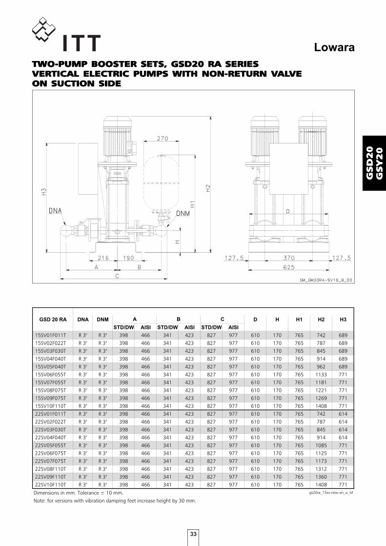
33
Lowara
GS
D2
0G
SD
20
GS
D2
0G
SD
20
GS
D2
0G
SY
20
GS
Y2
0G
SY
20
GS
Y2
0G
SY
20
GSD 20 RA DNA DNM D H H1 H2 H3
STD/DW AISI STD/DW AISI STD/DW AISI
15SV01F011T R 3" R 3" 398 466 341 423 827 977 610 170 765 742 689
15SV02F022T R 3" R 3" 398 466 341 423 827 977 610 170 765 787 689
15SV03F030T R 3" R 3" 398 466 341 423 827 977 610 170 765 845 689
15SV04F040T R 3" R 3" 398 466 341 423 827 977 610 170 765 914 689
15SV05F040T R 3" R 3" 398 466 341 423 827 977 610 170 765 962 689
15SV06F055T R 3" R 3" 398 466 341 423 827 977 610 170 765 1133 771
15SV07F055T R 3" R 3" 398 466 341 423 827 977 610 170 765 1181 771
15SV08F075T R 3" R 3" 398 466 341 423 827 977 610 170 765 1221 771
15SV09F075T R 3" R 3" 398 466 341 423 827 977 610 170 765 1269 771
15SV10F110T R 3" R 3" 398 466 341 423 827 977 610 170 765 1408 771
22SV01F011T R 3" R 3" 398 466 341 423 827 977 610 170 765 742 614
22SV02F022T R 3" R 3" 398 466 341 423 827 977 610 170 765 787 614
22SV03F030T R 3" R 3" 398 466 341 423 827 977 610 170 765 845 614
22SV04F040T R 3" R 3" 398 466 341 423 827 977 610 170 765 914 614
22SV05F055T R 3" R 3" 398 466 341 423 827 977 610 170 765 1085 771
22SV06F075T R 3" R 3" 398 466 341 423 827 977 610 170 765 1125 771
22SV07F075T R 3" R 3" 398 466 341 423 827 977 610 170 765 1173 771
22SV08F110T R 3" R 3" 398 466 341 423 827 977 610 170 765 1312 771
22SV09F110T R 3" R 3" 398 466 341 423 827 977 610 170 765 1360 771
22SV10F110T R 3" R 3" 398 466 341 423 827 977 610 170 765 1408 771
Dimensions in mm. Tolerance ± 10 mm. gs20ra_15sv-new-en_a_td
Note: for versions with vibration damping feet increase height by 30 mm.
A B C
TWOTWOTWOTWOTWO-PUMP BOOSTER SETS, GSD20 RA SERIES-PUMP BOOSTER SETS, GSD20 RA SERIES-PUMP BOOSTER SETS, GSD20 RA SERIES-PUMP BOOSTER SETS, GSD20 RA SERIES-PUMP BOOSTER SETS, GSD20 RA SERIESVERTICAL ELECTRIC PUMPS WITH NON-RETURN VVERTICAL ELECTRIC PUMPS WITH NON-RETURN VVERTICAL ELECTRIC PUMPS WITH NON-RETURN VVERTICAL ELECTRIC PUMPS WITH NON-RETURN VVERTICAL ELECTRIC PUMPS WITH NON-RETURN VALALALALALVEVEVEVEVEON SUCTION SIDEON SUCTION SIDEON SUCTION SIDEON SUCTION SIDEON SUCTION SIDE

34
Lowara
GS
D2
0G
SD
20
GS
D2
0G
SD
20
GS
D2
0G
SY
20
GS
Y2
0G
SY
20
GS
Y2
0G
SY
20
TWOTWOTWOTWOTWO-PUMP BOOSTER SETS, GSD20 SERIES-PUMP BOOSTER SETS, GSD20 SERIES-PUMP BOOSTER SETS, GSD20 SERIES-PUMP BOOSTER SETS, GSD20 SERIES-PUMP BOOSTER SETS, GSD20 SERIESVERTICAL ELECTRIC PUMPS WITH NON-RETURN VVERTICAL ELECTRIC PUMPS WITH NON-RETURN VVERTICAL ELECTRIC PUMPS WITH NON-RETURN VVERTICAL ELECTRIC PUMPS WITH NON-RETURN VVERTICAL ELECTRIC PUMPS WITH NON-RETURN VALALALALALVEVEVEVEVEON DISCHARGE SIDEON DISCHARGE SIDEON DISCHARGE SIDEON DISCHARGE SIDEON DISCHARGE SIDE

35
Lowara
GS
D2
0G
SD
20
GS
D2
0G
SD
20
GS
D2
0G
SY
20
GS
Y2
0G
SY
20
GS
Y2
0G
SY
20
GSD20 DNA DNM A B C D E F G H H1 H2 H3
SV3301/1F22T 100 80 448 701 1359 110 780 110 780 215 810 862 1017
SV3301F30T 100 80 448 701 1359 110 780 110 780 215 810 897 1017
SV3302/2F40T 100 80 448 701 1359 110 780 110 780 215 810 993 1017
SV3302/1F40T 100 80 448 701 1359 110 780 110 780 215 810 993 1017
SV3302F55T 100 80 448 701 1359 110 780 110 780 215 810 1069 1097
SV3303/2F55T 100 80 448 701 1359 110 780 110 780 215 810 1144 1097
SV3303/1F75T 100 80 448 701 1359 110 780 110 780 215 810 1136 1097
SV3303F75T 100 80 448 701 1359 110 780 110 780 215 810 1136 1097
SV3304/2F75T 100 80 448 701 1359 110 780 110 780 215 810 1211 1097
SV3304/1F110T 100 80 448 701 1401 110 780 110 780 215 810 1307 1571
SV3304F110T 100 80 448 701 1401 110 780 110 780 215 810 1307 1571
SV3305/2F110T 100 80 448 701 1401 110 780 110 780 215 810 1382 1571
SV3305/1F110T 100 80 448 701 1401 110 780 110 780 215 810 1382 1571
SV3305F150T 100 80 448 701 1401 110 780 110 780 215 810 1448 1571
SV3306/2F150T 100 80 448 701 1401 110 780 110 780 215 810 1523 1571
SV3306/1F150T 100 80 448 701 1401 110 780 110 780 215 810 1523 1571
SV3306F150T 100 80 448 701 1401 110 780 110 780 215 810 1523 1571
SV3307/2F150T 100 80 448 701 1401 110 780 110 780 215 810 1598 1571
SV4601/1F30T 125 100 484 739 1457 110 780 110 780 250 857 937 1017
SV4601F40T 125 100 484 739 1457 110 780 110 780 250 857 958 1017
SV4602/2F55T 125 100 484 739 1457 110 780 110 780 250 857 1109 1097
SV4602F75T 125 100 484 739 1457 110 780 110 780 250 857 1101 1097
SV4603/2F110T 125 100 484 739 1457 110 780 110 780 250 857 1272 1571
SV4603F110T 125 100 484 739 1457 110 780 110 780 250 857 1272 1571
SV4604/2F150T 125 100 484 739 1457 110 780 110 780 250 857 1413 1571
SV4604F150T 125 100 484 739 1457 110 780 110 780 250 857 1413 1571
SV4605/2F185T 125 100 484 739 1457 110 780 110 780 250 857 1488 1571
SV4605F185T 125 100 484 739 1457 110 780 110 780 250 857 1488 1571
SV4606/2F220T 125 100 484 739 1499 110 780 110 780 250 857 1563 1821
SV4606F220T 125 100 484 739 1499 110 780 110 780 250 857 1563 1821
SV6601/1F40T 150 125 504 780 1551 110 780 90 820 250 870 983 1017
SV6601F55T 150 125 504 780 1551 110 780 90 820 250 870 1059 1097
SV6602/2F75T 150 125 504 780 1551 110 780 90 820 250 870 1141 1097
SV6602/1F110T 150 125 504 780 1551 110 780 90 820 250 870 1237 1571
SV6602F110T 150 125 504 780 1551 110 780 90 820 250 870 1237 1571
SV6603/2F150T 150 125 504 780 1551 110 780 90 820 250 870 1393 1571
SV6603/1F150T 150 125 504 780 1551 110 780 90 820 250 870 1393 1571
SV6603F185T 150 125 504 780 1551 110 780 90 820 250 870 1393 1571
SV6604/2F185T 150 125 504 780 1551 110 780 90 820 250 870 1483 1571
SV6604/1F220T 150 125 504 780 1555 110 780 90 820 250 870 1483 1821
SV6604F220T 150 125 504 780 1555 110 780 90 820 250 870 1483 1821
SV9201/1F55T 200 150 529 794 1635 90 820 90 820 250 884 1059 1097
SV9201F75T 200 150 529 794 1635 90 820 90 820 250 884 1051 1097
SV9202/2F110T 200 150 529 794 1635 90 820 90 820 250 884 1237 1571
SV9202F150T 200 150 529 794 1635 90 820 90 820 250 884 1303 1571
SV9203/2F185T 200 150 529 794 1635 90 820 90 820 250 884 1393 1571
SV9203F220T 200 150 529 794 1635 90 820 90 820 250 884 1393 1821
Note: for versions with vibration damping feet increase height by 50 mm. gs20_sv46-en_a_td16
TWOTWOTWOTWOTWO-PUMP BOOSTER SETS, GSD20 SERIES-PUMP BOOSTER SETS, GSD20 SERIES-PUMP BOOSTER SETS, GSD20 SERIES-PUMP BOOSTER SETS, GSD20 SERIES-PUMP BOOSTER SETS, GSD20 SERIESVERTICAL ELECTRIC PUMPS WITH NON-RETURN VVERTICAL ELECTRIC PUMPS WITH NON-RETURN VVERTICAL ELECTRIC PUMPS WITH NON-RETURN VVERTICAL ELECTRIC PUMPS WITH NON-RETURN VVERTICAL ELECTRIC PUMPS WITH NON-RETURN VALALALALALVEVEVEVEVEON DISCHARGE SIDEON DISCHARGE SIDEON DISCHARGE SIDEON DISCHARGE SIDEON DISCHARGE SIDE

36
Lowara
GS
D2
0G
SD
20
GS
D2
0G
SD
20
GS
D2
0G
SY
20
GS
Y2
0G
SY
20
GS
Y2
0G
SY
20
TWOTWOTWOTWOTWO-PUMP BOOSTER SETS, GSD20 RA SERIES-PUMP BOOSTER SETS, GSD20 RA SERIES-PUMP BOOSTER SETS, GSD20 RA SERIES-PUMP BOOSTER SETS, GSD20 RA SERIES-PUMP BOOSTER SETS, GSD20 RA SERIESVERTICAL ELECTRIC PUMPS WITH NON-RETURN VVERTICAL ELECTRIC PUMPS WITH NON-RETURN VVERTICAL ELECTRIC PUMPS WITH NON-RETURN VVERTICAL ELECTRIC PUMPS WITH NON-RETURN VVERTICAL ELECTRIC PUMPS WITH NON-RETURN VALALALALALVEVEVEVEVEON SUCTION SIDEON SUCTION SIDEON SUCTION SIDEON SUCTION SIDEON SUCTION SIDE

37
Lowara
GS
D2
0G
SD
20
GS
D2
0G
SD
20
GS
D2
0G
SY
20
GS
Y2
0G
SY
20
GS
Y2
0G
SY
20
TWOTWOTWOTWOTWO-PUMP BOOSTER SETS, GSD20 RA SERIES-PUMP BOOSTER SETS, GSD20 RA SERIES-PUMP BOOSTER SETS, GSD20 RA SERIES-PUMP BOOSTER SETS, GSD20 RA SERIES-PUMP BOOSTER SETS, GSD20 RA SERIESVERTICAL ELECTRIC PUMPS WITH NON-RETURN VVERTICAL ELECTRIC PUMPS WITH NON-RETURN VVERTICAL ELECTRIC PUMPS WITH NON-RETURN VVERTICAL ELECTRIC PUMPS WITH NON-RETURN VVERTICAL ELECTRIC PUMPS WITH NON-RETURN VALALALALALVEVEVEVEVEON SUCTION SIDEON SUCTION SIDEON SUCTION SIDEON SUCTION SIDEON SUCTION SIDE
GSD20RA DNA DNM A B C D E F G H H1 H2 H3
SV3301/1F22T 100 80 713 436 1359 110 780 110 780 215 810 862 1017
SV3301F30T 100 80 713 436 1359 110 780 110 780 215 810 897 1017
SV3302/2F40T 100 80 713 436 1359 110 780 110 780 215 810 993 1017
SV3302/1F40T 100 80 713 436 1359 110 780 110 780 215 810 993 1017
SV3302F55T 100 80 713 436 1359 110 780 110 780 215 810 1069 1097
SV3303/2F55T 100 80 713 436 1359 110 780 110 780 215 810 1144 1097
SV3303/1F75T 100 80 713 436 1359 110 780 110 780 215 810 1136 1097
SV3303F75T 100 80 713 436 1359 110 780 110 780 215 810 1136 1097
SV3304/2F75T 100 80 713 436 1359 110 780 110 780 215 810 1211 1097
SV3304/1F110T 100 80 713 436 1359 110 780 110 780 215 810 1307 1571
SV3304F110T 100 80 713 436 1359 110 780 110 780 215 810 1307 1571
SV3305/2F110T 100 80 713 436 1359 110 780 110 780 215 810 1382 1571
SV3305/1F110T 100 80 713 436 1359 110 780 110 780 215 810 1382 1571
SV3305F150T 100 80 713 436 1359 110 780 110 780 215 810 1448 1571
SV3306/2F150T 100 80 713 436 1359 110 780 110 780 215 810 1523 1571
SV3306/1F150T 100 80 713 436 1359 110 780 110 780 215 810 1523 1571
SV3306F150T 100 80 713 436 1359 110 780 110 780 215 810 1523 1571
SV3307/2F150T 100 80 713 436 1359 110 780 110 780 215 810 1598 1571
SV4601/1F30T 125 100 752 471 1457 110 780 110 780 250 857 937 1017
SV4601F40T 125 100 752 471 1457 110 780 110 780 250 857 958 1017
SV4602/2F55T 125 100 752 471 1457 110 780 110 780 250 857 1109 1097
SV4602F75T 125 100 752 471 1457 110 780 110 780 250 857 1101 1097
SV4603/2F110T 125 100 752 471 1457 110 780 110 780 250 857 1272 1571
SV4603F110T 125 100 752 471 1457 110 780 110 780 250 857 1272 1571
SV4604/2F150T 125 100 752 471 1457 110 780 110 780 250 857 1413 1571
SV4604F150T 125 100 752 471 1457 110 780 110 780 250 857 1413 1571
SV4605/2F185T 125 100 752 471 1457 110 780 110 780 250 857 1488 1571
SV4605F185T 125 100 752 471 1457 110 780 110 780 250 857 1488 1571
SV4606/2F220T 125 100 752 471 1457 110 780 110 780 250 857 1563 1821
SV4606F220T 125 100 752 471 1457 110 780 110 780 250 857 1563 1821
SV6601/1F40T 150 125 794 490 1551 110 780 90 820 250 870 983 1017
SV6601F55T 150 125 794 490 1551 110 780 90 820 250 870 1059 1097
SV6602/2F75T 150 125 794 490 1551 110 780 90 820 250 870 1141 1097
SV6602/1F110T 150 125 794 490 1551 110 780 90 820 250 870 1237 1571
SV6602F110T 150 125 794 490 1551 110 780 90 820 250 870 1237 1571
SV6603/2F150T 150 125 794 490 1551 110 780 90 820 250 870 1393 1571
SV6603/1F150T 150 125 794 490 1551 110 780 90 820 250 870 1393 1571
SV6603F185T 150 125 794 490 1551 110 780 90 820 250 870 1393 1571
SV6604/2F185T 150 125 794 490 1551 110 780 90 820 250 870 1483 1571
SV6604/1F220T 150 125 794 490 1551 110 780 90 820 250 870 1483 1821
SV6604F220T 150 125 794 490 1551 110 780 90 820 250 870 1483 1821
SV9201/1F55T 200 150 819 504 1635 90 820 90 820 250 884 1059 1097
SV9201F75T 200 150 819 504 1635 90 820 90 820 250 884 1051 1097
SV9202/2F110T 200 150 819 504 1635 90 820 90 820 250 884 1237 1571
SV9202F150T 200 150 819 504 1635 90 820 90 820 250 884 1303 1571
SV9203/2F185T 200 150 819 504 1635 90 820 90 820 250 884 1393 1571
SV9203F220T 200 150 819 504 1635 90 820 90 820 250 884 1393 1821
Note: for versions with vibration damping feet increase height by 50 mm. gs20ra_sv46-en_a_td16

38
Lowara
GS
D2
0G
SD
20
GS
D2
0G
SD
20
GS
D2
0G
SY
20
GS
Y2
0G
SY
20
GS
Y2
0G
SY
20
GSY20 DNA DNM A B C H1 H2
SV6605/2F300T 150 125 504 780 1552 880 1702
SV6605/1F300T 150 125 504 780 1552 880 1702
SV6605F300T 150 125 504 780 1552 880 1702
SV9204/2F300T 200 150 529 794 1635 894 1612
SV9204F300T 200 150 529 794 1635 894 1612
SV9205/2F370T 200 150 529 794 1635 894 1702
Note: for versions with vibration damping feet increase height by 50 mm. gs20_sv-big-en_a_td
TWOTWOTWOTWOTWO-PUMP BOOSTER SETS, GSY20 SERIES-PUMP BOOSTER SETS, GSY20 SERIES-PUMP BOOSTER SETS, GSY20 SERIES-PUMP BOOSTER SETS, GSY20 SERIES-PUMP BOOSTER SETS, GSY20 SERIESVERTICAL ELECTRIC PUMPS WITH NON-RETURN VVERTICAL ELECTRIC PUMPS WITH NON-RETURN VVERTICAL ELECTRIC PUMPS WITH NON-RETURN VVERTICAL ELECTRIC PUMPS WITH NON-RETURN VVERTICAL ELECTRIC PUMPS WITH NON-RETURN VALALALALALVEVEVEVEVEON DISCHARGE SIDEON DISCHARGE SIDEON DISCHARGE SIDEON DISCHARGE SIDEON DISCHARGE SIDE
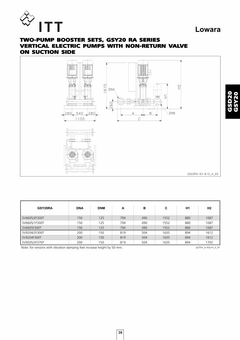
39
Lowara
GS
D2
0G
SD
20
GS
D2
0G
SD
20
GS
D2
0G
SY
20
GS
Y2
0G
SY
20
GS
Y2
0G
SY
20
GSY20RA DNA DNM A B C H1 H2
SV6605/2F300T 150 125 794 490 1552 880 1087
SV6605/1F300T 150 125 794 490 1552 880 1087
SV6605F300T 150 125 794 490 1552 880 1087
SV9204/2F300T 200 150 819 504 1635 894 1612
SV9204F300T 200 150 819 504 1635 894 1612
SV9205/2F370T 200 150 819 504 1635 894 1702
Note: for versions with vibration damping feet increase height by 50 mm. gs20ra_sv-big-en_a_td
TWOTWOTWOTWOTWO-PUMP BOOSTER SETS, GSY20 RA SERIES-PUMP BOOSTER SETS, GSY20 RA SERIES-PUMP BOOSTER SETS, GSY20 RA SERIES-PUMP BOOSTER SETS, GSY20 RA SERIES-PUMP BOOSTER SETS, GSY20 RA SERIESVERTICAL ELECTRIC PUMPS WITH NON-RETURN VVERTICAL ELECTRIC PUMPS WITH NON-RETURN VVERTICAL ELECTRIC PUMPS WITH NON-RETURN VVERTICAL ELECTRIC PUMPS WITH NON-RETURN VVERTICAL ELECTRIC PUMPS WITH NON-RETURN VALALALALALVEVEVEVEVEON SUCTION SIDEON SUCTION SIDEON SUCTION SIDEON SUCTION SIDEON SUCTION SIDE

40
Lowara
GS
D2
0G
SD
20
GS
D2
0G
SD
20
GS
D2
0G
SY
20
GS
Y2
0G
SY
20
GS
Y2
0G
SY
20

41
Lowara
GS
D2
1G
SD
21
GS
D2
1G
SD
21
GS
D2
1G
SY
21
GS
Y2
1G
SY
21
GS
Y2
1G
SY
21
BoosterBoosterBoosterBoosterBoostersetssetssetssetssets
MARKET SECTORSMARKET SECTORSMARKET SECTORSMARKET SECTORSMARKET SECTORSCIVIL, INDUSTRIAL
APPLICAAPPLICAAPPLICAAPPLICAAPPLICATIONSTIONSTIONSTIONSTIONS• Water network supply in condominiums, offices, hotels, shopping centres, factories.• Water supply to agricultural water networks (e.g. irrigation).
SPECIFICASPECIFICASPECIFICASPECIFICASPECIFICATIONSTIONSTIONSTIONSTIONS
• Flow rateFlow rateFlow rateFlow rateFlow rate up to 240 m3/h.
• HeadHeadHeadHeadHead up to 160 m.
• Electrical panel supply voltage: 3 x 400V ± 10%.
• Frequency 50 Hz.
• Voltage for controls outside panel: 24 Vac.
• Electrical panel protection class IP 55.
• Maximum service pump power: 2 x 37 kW.
• Motor start-up : - Direct for powers up to 22 kW inclusive for pump (GSD/). - Star/Delta for higher powers (GSY/ set).- Softstarter, available on request (GSSF/ set).
• Electric pumps withElectric pumps withElectric pumps withElectric pumps withElectric pumps with vertical axis vertical axis vertical axis vertical axis vertical axis: - SV series (motor protection class IP55).• Electric jockElectric jockElectric jockElectric jockElectric jockey pumpsey pumpsey pumpsey pumpsey pumps with vertical axis with vertical axis with vertical axis with vertical axis with vertical axis: - SV series (motor protection class IP55).• Maximum operating pressure: 16 bar.• Maximum temperature of pumped liquid : +80°C.
GSD21 - GSY21GSD21 - GSY21GSD21 - GSY21GSD21 - GSY21GSD21 - GSY21SeriesSeriesSeriesSeriesSeries

42
Lowara
GS
D2
1G
SD
21
GS
D2
1G
SD
21
GS
D2
1G
SY
21
GS
Y2
1G
SY
21
GS
Y2
1G
SY
21
GSD 21 DNA DNM D H H1 H2 H3
STD/DW AISI STD/DW AISI STD/DW AISI
10SV01F007T R 2"1/2 R 2"1/2 301 356 366 497 825 956 1040 160 748 700 973
10SV02F007T R 2"1/2 R 2"1/2 301 356 366 497 825 956 1040 160 748 700 973
10SV03F011T R 2"1/2 R 2"1/2 301 356 366 497 825 956 1040 160 748 732 973
10SV04F015T R 2"1/2 R 2"1/2 301 356 366 497 825 956 1040 160 748 809 973
10SV05F022T R 2"1/2 R 2"1/2 301 356 366 497 825 956 1040 160 748 841 973
10SV06F022T R 2"1/2 R 2"1/2 301 356 366 497 825 956 1040 160 748 873 973
10SV07F030T R 2"1/2 R 2"1/2 301 356 366 497 825 956 1040 160 748 915 973
10SV08F030T R 2"1/2 R 2"1/2 301 356 366 497 825 956 1040 160 748 947 973
10SV09F040T R 2"1/2 R 2"1/2 301 356 366 497 825 956 1040 160 748 1000 973
10SV10F040T R 2"1/2 R 2"1/2 301 356 366 497 825 956 1040 160 748 1032 973
10SV11F040T R 2"1/2 R 2"1/2 301 356 366 497 825 956 1040 160 748 1064 973
10SV13F055T R 2"1/2 R 2"1/2 301 356 366 497 825 956 1040 160 748 1251 973
Dimensions in mm. Tolerance ± 10 mm. gs21_10sv-new-en_a_td
A B C
TWOTWOTWOTWOTWO-PUMP BOOSTER SETS, GSD21 SERIES-PUMP BOOSTER SETS, GSD21 SERIES-PUMP BOOSTER SETS, GSD21 SERIES-PUMP BOOSTER SETS, GSD21 SERIES-PUMP BOOSTER SETS, GSD21 SERIESVERTICAL ELECTRIC PUMPS WITH JOCKEY PUMPVERTICAL ELECTRIC PUMPS WITH JOCKEY PUMPVERTICAL ELECTRIC PUMPS WITH JOCKEY PUMPVERTICAL ELECTRIC PUMPS WITH JOCKEY PUMPVERTICAL ELECTRIC PUMPS WITH JOCKEY PUMPNON-RETURN VNON-RETURN VNON-RETURN VNON-RETURN VNON-RETURN VALALALALALVE ON DISCHARGE SIDEVE ON DISCHARGE SIDEVE ON DISCHARGE SIDEVE ON DISCHARGE SIDEVE ON DISCHARGE SIDE

43
Lowara
GS
D2
1G
SD
21
GS
D2
1G
SD
21
GS
D2
1G
SY
21
GS
Y2
1G
SY
21
GS
Y2
1G
SY
21
GSD 21RA DNA DNM D H H1 H2 H3
STD/DW AISI STD/DW AISI STD/DW AISI
10SV01F007T R 2"1/2 R 2"1/2 359 497 301 356 760 929 1040 160 748 700 973
10SV02F007T R 2"1/2 R 2"1/2 359 497 301 356 760 929 1040 160 748 700 973
10SV03F011T R 2"1/2 R 2"1/2 359 497 301 356 760 929 1040 160 748 732 973
10SV04F015T R 2"1/2 R 2"1/2 359 497 301 356 760 929 1040 160 748 809 973
10SV05F022T R 2"1/2 R 2"1/2 359 497 301 356 760 929 1040 160 748 841 973
10SV06F022T R 2"1/2 R 2"1/2 359 497 301 356 760 929 1040 160 748 873 973
10SV07F030T R 2"1/2 R 2"1/2 359 497 301 356 760 929 1040 160 748 915 973
10SV08F030T R 2"1/2 R 2"1/2 359 497 301 356 760 929 1040 160 748 947 973
10SV09F040T R 2"1/2 R 2"1/2 359 497 301 356 760 929 1040 160 748 1000 973
10SV10F040T R 2"1/2 R 2"1/2 359 497 301 356 760 929 1040 160 748 1032 973
10SV11F040T R 2"1/2 R 2"1/2 359 497 301 356 760 929 1040 160 748 1064 973
10SV13F055T R 2"1/2 R 2"1/2 359 497 301 356 760 929 1040 160 748 1251 973
Dimensions in mm. Tolerance ± 10 mm. gs21ra_10sv-new-en_a_td
Note: for versions with vibration damping feet increase height by 30 mm.
A B C
TWOTWOTWOTWOTWO-PUMP BOOSTER SETS, GSD21 RA SERIES-PUMP BOOSTER SETS, GSD21 RA SERIES-PUMP BOOSTER SETS, GSD21 RA SERIES-PUMP BOOSTER SETS, GSD21 RA SERIES-PUMP BOOSTER SETS, GSD21 RA SERIESVERTICAL ELECTRIC PUMPS WITH JOCKEY PUMPVERTICAL ELECTRIC PUMPS WITH JOCKEY PUMPVERTICAL ELECTRIC PUMPS WITH JOCKEY PUMPVERTICAL ELECTRIC PUMPS WITH JOCKEY PUMPVERTICAL ELECTRIC PUMPS WITH JOCKEY PUMPNON-RETURN VNON-RETURN VNON-RETURN VNON-RETURN VNON-RETURN VALALALALALVE ON SUCTION SIDEVE ON SUCTION SIDEVE ON SUCTION SIDEVE ON SUCTION SIDEVE ON SUCTION SIDE

44
Lowara
GS
D2
1G
SD
21
GS
D2
1G
SD
21
GS
D2
1G
SY
21
GS
Y2
1G
SY
21
GS
Y2
1G
SY
21
GSD 21 DNA DNM D H H1 H2 H3
STD/DW AISI STD/DW AISI STD/DW AISI
15SV01F011T R 3" R 3" 341 423 398 466 827 977 1040 170 765 742 973
15SV02F022T R 3" R 3" 341 423 398 466 827 977 1040 170 765 787 973
15SV03F030T R 3" R 3" 341 423 398 466 827 977 1040 170 765 845 973
15SV04F040T R 3" R 3" 341 423 398 466 827 977 1040 170 765 914 973
15SV05F040T R 3" R 3" 341 423 398 466 827 977 1040 170 765 962 973
15SV06F055T R 3" R 3" 341 423 398 466 827 977 1040 170 765 1133 973
15SV07F055T R 3" R 3" 341 423 398 466 827 977 1040 170 765 1181 973
15SV08F075T R 3" R 3" 341 423 398 466 827 977 1040 170 765 1221 973
15SV09F075T R 3" R 3" 341 423 398 466 827 977 1040 170 765 1269 973
15SV10F110T R 3" R 3" 341 423 398 466 827 977 1040 170 765 1408 1570
22SV01F011T R 3" R 3" 341 423 398 466 827 977 1040 170 765 742 973
22SV02F022T R 3" R 3" 341 423 398 466 827 977 1040 170 765 787 973
22SV03F030T R 3" R 3" 341 423 398 466 827 977 1040 170 765 845 973
22SV04F040T R 3" R 3" 341 423 398 466 827 977 1040 170 765 914 973
22SV05F055T R 3" R 3" 341 423 398 466 827 977 1040 170 765 1085 973
22SV06F075T R 3" R 3" 341 423 398 466 827 977 1040 170 765 1125 973
22SV07F075T R 3" R 3" 341 423 398 466 827 977 1040 170 765 1173 973
22SV08F110T R 3" R 3" 341 423 398 466 827 977 1040 170 765 1312 1570
22SV09F110T R 3" R 3" 341 423 398 466 827 977 1040 170 765 1360 1570
22SV10F110T R 3" R 3" 341 423 398 466 827 977 1040 170 765 1408 1570
Dimensions in mm. Tolerance ± 10 mm. gs21_15sv-new-en_a_td
Note: for versions with vibration damping feet increase height by 30 mm.
A B C
TWOTWOTWOTWOTWO-PUMP BOOSTER SETS, GSD21 SERIES-PUMP BOOSTER SETS, GSD21 SERIES-PUMP BOOSTER SETS, GSD21 SERIES-PUMP BOOSTER SETS, GSD21 SERIES-PUMP BOOSTER SETS, GSD21 SERIESVERTICAL ELECTRIC PUMPS WITH JOCKEY PUMPVERTICAL ELECTRIC PUMPS WITH JOCKEY PUMPVERTICAL ELECTRIC PUMPS WITH JOCKEY PUMPVERTICAL ELECTRIC PUMPS WITH JOCKEY PUMPVERTICAL ELECTRIC PUMPS WITH JOCKEY PUMPNON-RETURN VNON-RETURN VNON-RETURN VNON-RETURN VNON-RETURN VALALALALALVE ON DISCHARGE SIDEVE ON DISCHARGE SIDEVE ON DISCHARGE SIDEVE ON DISCHARGE SIDEVE ON DISCHARGE SIDE

45
Lowara
GS
D2
1G
SD
21
GS
D2
1G
SD
21
GS
D2
1G
SY
21
GS
Y2
1G
SY
21
GS
Y2
1G
SY
21
GSD 21 RA DNA DNM D H H1 H2 H3
STD/DW AISI STD/DW AISI STD/DW AISI
15SV01F011T R 3" R 3" 398 466 341 423 827 977 1040 170 765 742 973
15SV02F022T R 3" R 3" 398 466 341 423 827 977 1040 170 765 787 973
15SV03F030T R 3" R 3" 398 466 341 423 827 977 1040 170 765 845 973
15SV04F040T R 3" R 3" 398 466 341 423 827 977 1040 170 765 914 973
15SV05F040T R 3" R 3" 398 466 341 423 827 977 1040 170 765 962 973
15SV06F055T R 3" R 3" 398 466 341 423 827 977 1040 170 765 1133 973
15SV07F055T R 3" R 3" 398 466 341 423 827 977 1040 170 765 1181 973
15SV08F075T R 3" R 3" 398 466 341 423 827 977 1040 170 765 1221 973
15SV09F075T R 3" R 3" 398 466 341 423 827 977 1040 170 765 1269 973
15SV10F110T R 3" R 3" 398 466 341 423 827 977 1040 170 765 1408 1570
22SV01F011T R 3" R 3" 398 466 341 423 827 977 1040 170 765 742 973
22SV02F022T R 3" R 3" 398 466 341 423 827 977 1040 170 765 787 973
22SV03F030T R 3" R 3" 398 466 341 423 827 977 1040 170 765 845 973
22SV04F040T R 3" R 3" 398 466 341 423 827 977 1040 170 765 914 973
22SV05F055T R 3" R 3" 398 466 341 423 827 977 1040 170 765 1085 973
22SV06F075T R 3" R 3" 398 466 341 423 827 977 1040 170 765 1125 973
22SV07F075T R 3" R 3" 398 466 341 423 827 977 1040 170 765 1173 973
22SV08F110T R 3" R 3" 398 466 341 423 827 977 1040 170 765 1312 1570
22SV09F110T R 3" R 3" 398 466 341 423 827 977 1040 170 765 1360 1570
22SV10F110T R 3" R 3" 398 466 341 423 827 977 1040 170 765 1408 1570
Dimensions in mm. Tolerance ± 10 mm. gs21ra_15sv-new-en_a_td
Note: for versions with vibration damping feet increase height by 30 mm.
A B C
TWOTWOTWOTWOTWO-PUMP BOOSTER SETS, GSD21 RA SERIES-PUMP BOOSTER SETS, GSD21 RA SERIES-PUMP BOOSTER SETS, GSD21 RA SERIES-PUMP BOOSTER SETS, GSD21 RA SERIES-PUMP BOOSTER SETS, GSD21 RA SERIESVERTICAL ELECTRIC PUMPS WITH JOCKEY PUMPVERTICAL ELECTRIC PUMPS WITH JOCKEY PUMPVERTICAL ELECTRIC PUMPS WITH JOCKEY PUMPVERTICAL ELECTRIC PUMPS WITH JOCKEY PUMPVERTICAL ELECTRIC PUMPS WITH JOCKEY PUMPNON-RETURN VNON-RETURN VNON-RETURN VNON-RETURN VNON-RETURN VALALALALALVE ON SUCTION SIDEVE ON SUCTION SIDEVE ON SUCTION SIDEVE ON SUCTION SIDEVE ON SUCTION SIDE

46
Lowara
GS
D2
1G
SD
21
GS
D2
1G
SD
21
GS
D2
1G
SY
21
GS
Y2
1G
SY
21
GS
Y2
1G
SY
21
TWOTWOTWOTWOTWO-PUMP BOOSTER SETS, GSD..Y21 SERIES-PUMP BOOSTER SETS, GSD..Y21 SERIES-PUMP BOOSTER SETS, GSD..Y21 SERIES-PUMP BOOSTER SETS, GSD..Y21 SERIES-PUMP BOOSTER SETS, GSD..Y21 SERIESVERTICAL ELECTRIC PUMPS WITH JOCKEY PUMPVERTICAL ELECTRIC PUMPS WITH JOCKEY PUMPVERTICAL ELECTRIC PUMPS WITH JOCKEY PUMPVERTICAL ELECTRIC PUMPS WITH JOCKEY PUMPVERTICAL ELECTRIC PUMPS WITH JOCKEY PUMPNON-RETURN VNON-RETURN VNON-RETURN VNON-RETURN VNON-RETURN VALALALALALVE ON DISCHARGE SIDEVE ON DISCHARGE SIDEVE ON DISCHARGE SIDEVE ON DISCHARGE SIDEVE ON DISCHARGE SIDE

47
Lowara
GS
D2
1G
SD
21
GS
D2
1G
SD
21
GS
D2
1G
SY
21
GS
Y2
1G
SY
21
GS
Y2
1G
SY
21
TWOTWOTWOTWOTWO-PUMP BOOSTER SETS, GSD..Y21 SERIES-PUMP BOOSTER SETS, GSD..Y21 SERIES-PUMP BOOSTER SETS, GSD..Y21 SERIES-PUMP BOOSTER SETS, GSD..Y21 SERIES-PUMP BOOSTER SETS, GSD..Y21 SERIESVERTICAL ELECTRIC PUMPS WITH JOCKEY PUMPVERTICAL ELECTRIC PUMPS WITH JOCKEY PUMPVERTICAL ELECTRIC PUMPS WITH JOCKEY PUMPVERTICAL ELECTRIC PUMPS WITH JOCKEY PUMPVERTICAL ELECTRIC PUMPS WITH JOCKEY PUMPNON-RETURN VNON-RETURN VNON-RETURN VNON-RETURN VNON-RETURN VALALALALALVE ON DISCHARGE SIDEVE ON DISCHARGE SIDEVE ON DISCHARGE SIDEVE ON DISCHARGE SIDEVE ON DISCHARGE SIDE
GSD21 / GSY21 DNA DNM A B C D E F G H H1 H2 H3
SV3301/1F22T 100 80 448 701 1359 110 1220 110 1220 215 810 862 974
SV3301F30T 100 80 448 701 1359 110 1220 110 1220 215 810 897 974
SV3302/2F40T 100 80 448 701 1359 110 1220 110 1220 215 810 993 974
SV3302/1F40T 100 80 448 701 1359 110 1220 110 1220 215 810 993 974
SV3302F55T 100 80 448 701 1359 110 1220 110 1220 215 810 1069 974
SV3303/2F55T 100 80 448 701 1359 110 1220 110 1220 215 810 1144 974
SV3303/1F75T 100 80 448 701 1359 110 1220 110 1220 215 810 1136 974
SV3303F75T 100 80 448 701 1359 110 1220 110 1220 215 810 1136 974
SV3304/2F75T 100 80 448 701 1359 110 1220 110 1220 215 810 1211 974
SV3304/1F110T 100 80 448 701 1451 110 1220 110 1220 215 810 1307 1571
SV3304F110T 100 80 448 701 1451 110 1220 110 1220 215 810 1307 1571
SV3305/2F110T 100 80 448 701 1451 110 1220 110 1220 215 810 1382 1571
SV3305/1F110T 100 80 448 701 1451 110 1220 110 1220 215 810 1382 1571
SV3305F150T 100 80 448 701 1451 110 1220 110 1220 215 810 1448 1571
SV3306/2F150T 100 80 448 701 1451 110 1220 110 1220 215 810 1523 1571
SV3306/1F150T 100 80 448 701 1451 110 1220 110 1220 215 810 1523 1571
SV3306F150T 100 80 448 701 1451 110 1220 110 1220 215 810 1523 1571
SV3307/2F150T 100 80 448 701 1451 110 1220 110 1220 215 810 1598 1571
SV4601/1F30T 125 100 484 739 1457 110 1220 110 1220 250 857 937 974
SV4601F40T 125 100 484 739 1457 110 1220 110 1220 250 857 958 974
SV4602/2F55T 125 100 484 739 1457 110 1220 110 1220 250 857 1109 974
SV4602F75T 125 100 484 739 1457 110 1220 110 1220 250 857 1101 974
SV4603/2F110T 125 100 484 739 1499 110 1220 110 1220 250 857 1272 1571
SV4603F110T 125 100 484 739 1499 110 1220 110 1220 250 857 1272 1571
SV4604/2F150T 125 100 484 739 1499 110 1220 110 1220 250 857 1413 1571
SV4604F150T 125 100 484 739 1499 110 1220 110 1220 250 857 1413 1571
SV4605/2F185T 125 100 484 739 1499 110 1220 110 1220 250 857 1488 1571
SV4605F185T 125 100 484 739 1499 110 1220 110 1220 250 857 1488 1571
SV4606/2F220T 125 100 484 739 1499 110 1220 110 1220 250 857 1563 1571
SV4606F220T 125 100 484 739 1499 110 1220 110 1220 250 857 1563 1571
SV6601/1F40T 150 125 504 780 1551 110 1220 90 1260 250 870 983 1194
SV6601F55T 150 125 504 780 1551 110 1220 90 1260 250 870 1059 1194
SV6602/2F75T 150 125 504 780 1551 110 1220 90 1260 250 870 1141 1194
SV6602/1F110T 150 125 504 780 1555 110 1220 90 1260 250 870 1237 1571
SV6602F110T 150 125 504 780 1555 110 1220 90 1260 250 870 1237 1571
SV6603/2F150T 150 125 504 780 1555 110 1220 90 1260 250 870 1393 1571
SV6603/1F150T 150 125 504 780 1555 110 1220 90 1260 250 870 1393 1571
SV6603F185T 150 125 504 780 1555 110 1220 90 1260 250 870 1393 1571
SV6604/2F185T 150 125 504 780 1555 110 1220 90 1260 250 870 1483 1571
SV6604/1F220T 150 125 504 780 1555 110 1220 90 1260 250 870 1483 1571
SV6604F220T 150 125 504 780 1555 110 1220 90 1260 250 870 1483 1571
SV6605/2F300T 150 125 504 780 1555 110 1220 90 1260 250 870 1692 1571
SV6605/1F300T 150 125 504 780 1555 110 1220 90 1260 250 870 1692 1571
SV6605F300T 150 125 504 780 1555 110 1220 90 1260 250 870 1692 1571
SV9201/1F55T 200 150 529 794 1635 90 1260 90 1260 250 884 1059 1194
SV9201F75T 200 150 529 794 1635 90 1260 90 1260 250 884 1051 1194
SV9202/2F110T 200 150 529 794 1635 90 1260 90 1260 250 884 1237 1821
SV9202F150T 200 150 529 794 1635 90 1260 90 1260 250 884 1303 1821
SV9203/2F185T 200 150 529 794 1635 90 1260 90 1260 250 884 1393 1821
SV9203F220T 200 150 529 794 1635 90 1260 90 1260 250 884 1393 1821
SV9204/2F300T 200 150 529 794 1635 90 1260 90 1260 250 884 1599 1821
SV9204F300T 200 150 529 794 1635 90 1260 90 1260 250 884 1599 1821
SV9205/2F370T
Note: for versions with vibration damping feet increase height by 50 mm. gs21_sv46-en_a_td16
DIMENSIONS ON REQUEST
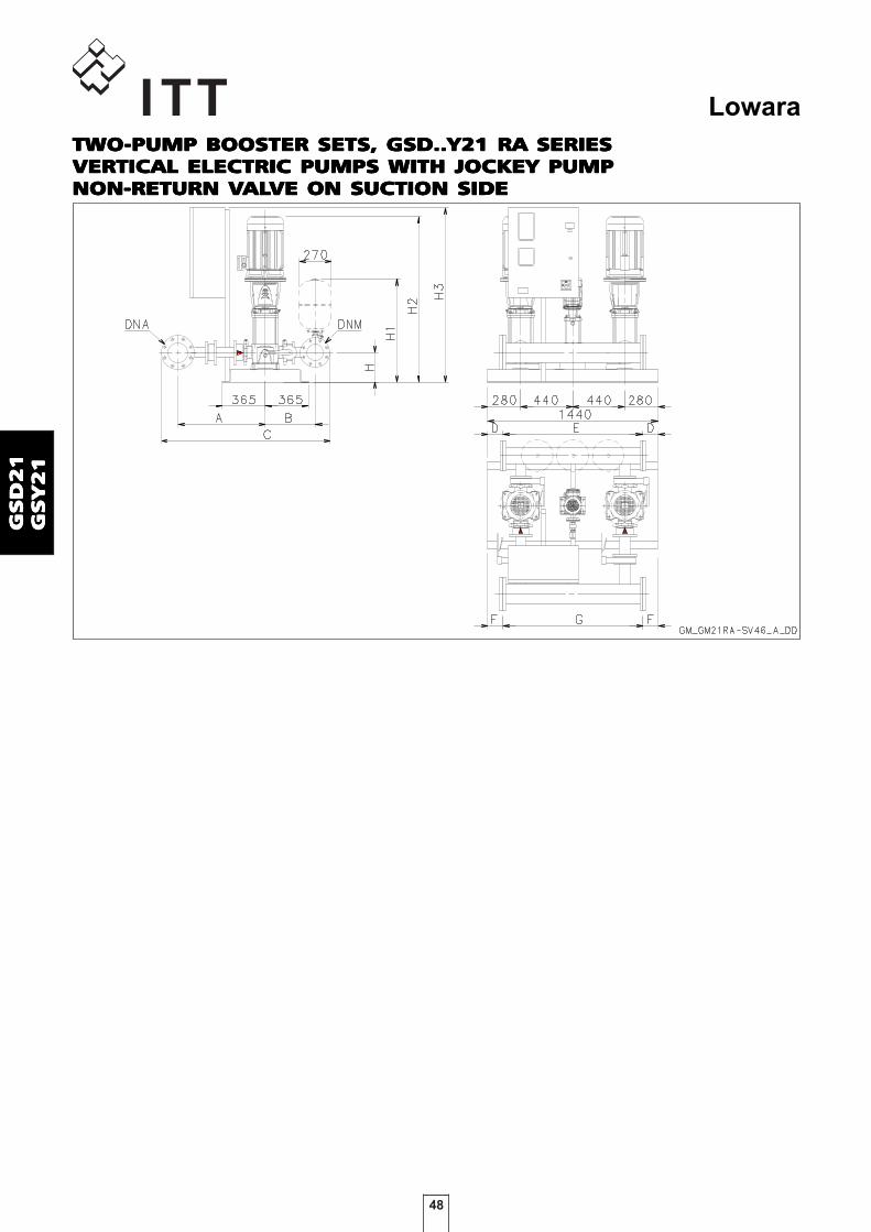
48
Lowara
GS
D2
1G
SD
21
GS
D2
1G
SD
21
GS
D2
1G
SY
21
GS
Y2
1G
SY
21
GS
Y2
1G
SY
21
TWOTWOTWOTWOTWO-PUMP BOOSTER SETS, GSD..Y21 RA SERIES-PUMP BOOSTER SETS, GSD..Y21 RA SERIES-PUMP BOOSTER SETS, GSD..Y21 RA SERIES-PUMP BOOSTER SETS, GSD..Y21 RA SERIES-PUMP BOOSTER SETS, GSD..Y21 RA SERIESVERTICAL ELECTRIC PUMPS WITH JOCKEY PUMPVERTICAL ELECTRIC PUMPS WITH JOCKEY PUMPVERTICAL ELECTRIC PUMPS WITH JOCKEY PUMPVERTICAL ELECTRIC PUMPS WITH JOCKEY PUMPVERTICAL ELECTRIC PUMPS WITH JOCKEY PUMPNON-RETURN VNON-RETURN VNON-RETURN VNON-RETURN VNON-RETURN VALALALALALVE ON SUCTION SIDEVE ON SUCTION SIDEVE ON SUCTION SIDEVE ON SUCTION SIDEVE ON SUCTION SIDE

49
Lowara
GS
D2
1G
SD
21
GS
D2
1G
SD
21
GS
D2
1G
SY
21
GS
Y2
1G
SY
21
GS
Y2
1G
SY
21
TWOTWOTWOTWOTWO-PUMP BOOSTER SETS, GSD..Y21 RA SERIES-PUMP BOOSTER SETS, GSD..Y21 RA SERIES-PUMP BOOSTER SETS, GSD..Y21 RA SERIES-PUMP BOOSTER SETS, GSD..Y21 RA SERIES-PUMP BOOSTER SETS, GSD..Y21 RA SERIESVERTICAL ELECTRIC PUMPS WITH JOCKEY PUMPVERTICAL ELECTRIC PUMPS WITH JOCKEY PUMPVERTICAL ELECTRIC PUMPS WITH JOCKEY PUMPVERTICAL ELECTRIC PUMPS WITH JOCKEY PUMPVERTICAL ELECTRIC PUMPS WITH JOCKEY PUMPNON-RETURN VNON-RETURN VNON-RETURN VNON-RETURN VNON-RETURN VALALALALALVE ON SUCTION SIDEVE ON SUCTION SIDEVE ON SUCTION SIDEVE ON SUCTION SIDEVE ON SUCTION SIDE
GSD21RA / GSY21RA DNA DNM A B C D E F G H H1 H2 H3
SV3301/1F22T 100 80 713 436 1359 110 1220 110 1220 215 810 862 974
SV3301F30T 100 80 713 436 1359 110 1220 110 1220 215 810 897 974
SV3302/2F40T 100 80 713 436 1359 110 1220 110 1220 215 810 993 974
SV3302/1F40T 100 80 713 436 1359 110 1220 110 1220 215 810 993 974
SV3302F55T 100 80 713 436 1359 110 1220 110 1220 215 810 1069 974
SV3303/2F55T 100 80 713 436 1359 110 1220 110 1220 215 810 1144 974
SV3303/1F75T 100 80 713 436 1359 110 1220 110 1220 215 810 1136 974
SV3303F75T 100 80 713 436 1359 110 1220 110 1220 215 810 1136 974
SV3304/2F75T 100 80 713 436 1359 110 1220 110 1220 215 810 1211 974
SV3304/1F110T 100 80 713 436 1359 110 1220 110 1220 215 810 1307 1571
SV3304F110T 100 80 713 436 1359 110 1220 110 1220 215 810 1307 1571
SV3305/2F110T 100 80 713 436 1359 110 1220 110 1220 215 810 1382 1571
SV3305/1F110T 100 80 713 436 1359 110 1220 110 1220 215 810 1382 1571
SV3305F150T 100 80 713 436 1359 110 1220 110 1220 215 810 1448 1571
SV3306/2F150T 100 80 713 436 1359 110 1220 110 1220 215 810 1523 1571
SV3306/1F150T 100 80 713 436 1359 110 1220 110 1220 215 810 1523 1571
SV3306F150T 100 80 713 436 1359 110 1220 110 1220 215 810 1523 1571
SV3307/2F150T 100 80 713 436 1359 110 1220 110 1220 215 810 1598 1571
SV4601/1F30T 125 100 752 471 1457 110 1220 110 1220 250 857 937 974
SV4601F40T 125 100 752 471 1457 110 1220 110 1220 250 857 958 974
SV4602/2F55T 125 100 752 471 1457 110 1220 110 1220 250 857 1109 974
SV4602F75T 125 100 752 471 1457 110 1220 110 1220 250 857 1101 974
SV4603/2F110T 125 100 752 471 1457 110 1220 110 1220 250 857 1272 1571
SV4603F110T 125 100 752 471 1457 110 1220 110 1220 250 857 1272 1571
SV4604/2F150T 125 100 752 471 1457 110 1220 110 1220 250 857 1413 1571
SV4604F150T 125 100 752 471 1457 110 1220 110 1220 250 857 1413 1571
SV4605/2F185T 125 100 752 471 1457 110 1220 110 1220 250 857 1488 1571
SV4605F185T 125 100 752 471 1457 110 1220 110 1220 250 857 1488 1571
SV4606/2F220T 125 100 752 471 1457 110 1220 110 1220 250 857 1563 1571
SV4606F220T 125 100 752 471 1457 110 1220 110 1220 250 857 1563 1571
SV6601/1F40T 150 125 794 490 1551 110 1220 90 1260 250 870 983 1194
SV6601F55T 150 125 794 490 1551 110 1220 90 1260 250 870 1059 1194
SV6602/2F75T 150 125 794 490 1551 110 1220 90 1260 250 870 1141 1194
SV6602/1F110T 150 125 794 490 1551 110 1220 90 1260 250 870 1237 1571
SV6602F110T 150 125 794 490 1551 110 1220 90 1260 250 870 1237 1571
SV6603/2F150T 150 125 794 490 1551 110 1220 90 1260 250 870 1393 1571
SV6603/1F150T 150 125 794 490 1551 110 1220 90 1260 250 870 1393 1571
SV6603F185T 150 125 794 490 1551 110 1220 90 1260 250 870 1393 1571
SV6604/2F185T 150 125 794 490 1551 110 1220 90 1260 250 870 1483 1571
SV6604/1F220T 150 125 794 490 1551 110 1220 90 1260 250 870 1483 1571
SV6604F220T 150 125 794 490 1551 110 1220 90 1260 250 870 1483 1571
SV6605/2F300T 150 125 794 490 1551 110 1220 90 1260 250 870 1692 1571
SV6605/1F300T 150 125 794 490 1551 110 1220 90 1260 250 870 1692 1571
SV6605F300T 150 125 794 490 1551 110 1220 90 1260 250 870 1692 1571
SV9201/1F55T 200 150 819 504 1635 90 1260 90 1260 250 884 1059 1194
SV9201F75T 200 150 819 504 1635 90 1260 90 1260 250 884 1051 1194
SV9202/2F110T 200 150 819 504 1635 90 1260 90 1260 250 884 1237 1821
SV9202F150T 200 150 819 504 1635 90 1260 90 1260 250 884 1303 1821
SV9203/2F185T 200 150 819 504 1635 90 1260 90 1260 250 884 1393 1821
SV9203F220T 200 150 819 504 1635 90 1260 90 1260 250 884 1393 1821
SV9204/2F300T 200 150 819 504 1635 90 1260 90 1260 250 884 1599 1821
SV9204F300T 200 150 819 504 1635 90 1260 90 1260 250 884 1599 1821
SV9205/2F370T
Note: for versions with vibration damping feet increase height by 50 mm. gs21ra_sv46-en_a_td16
DIMENSIONS ON REQUEST

50
Lowara
GS
D2
1G
SD
21
GS
D2
1G
SD
21
GS
D2
1G
SY
21
GS
Y2
1G
SY
21
GS
Y2
1G
SY
21

51
Lowara
GS
D3
0G
SD
30
GS
D3
0G
SD
30
GS
D3
0G
SY
30
GS
Y3
0G
SY
30
GS
Y3
0G
SY
30
BoosterBoosterBoosterBoosterBoostersetssetssetssetssets
MARKET SECTORSMARKET SECTORSMARKET SECTORSMARKET SECTORSMARKET SECTORSCIVIL, INDUSTRIAL
APPLICAAPPLICAAPPLICAAPPLICAAPPLICATIONSTIONSTIONSTIONSTIONS• Water network supply in condominiums, offices, hotels, shopping centres, factories.• Water supply to agricultural water networks (e.g. irrigation).
GSD30 - GSY30GSD30 - GSY30GSD30 - GSY30GSD30 - GSY30GSD30 - GSY30SeriesSeriesSeriesSeriesSeries
SPECIFICASPECIFICASPECIFICASPECIFICASPECIFICATIONSTIONSTIONSTIONSTIONS
• Flow rateFlow rateFlow rateFlow rateFlow rate up to 360 m3/h.
• HeadHeadHeadHeadHead up to 160 m.
• Electrical panel supply voltage : 3 x 400V ± 10%.
• Frequency 50 Hz.
• Voltage for controls outside panel: 24 Vac.
• Electrical panel protection class IP 55.
• Maximum service pump power: 3 x 37 kW.
• Motor start-up : - Direct for powers up to 22 kW inclusive for pump (GSD/). - Star/Delta for higher powers (GSY/ set). - Softstarter, available on request (GSSF/ set).
• Electric pump withElectric pump withElectric pump withElectric pump withElectric pump with vertical axis vertical axis vertical axis vertical axis vertical axis: - SV series (motor protection class IP55).• Maximum operating pressure 16 bar.• Maximum temperature of pumped liquid : +80°C.

52
Lowara
GS
D3
0G
SD
30
GS
D3
0G
SD
30
GS
D3
0G
SY
30
GS
Y3
0G
SY
30
GS
Y3
0G
SY
30
GSD 30 DNA DNM D H H1 H2 H3
STD/DW AISI STD/DW AISI STD/DW AISI
10SV01F007T R 2"1/2 R 2"1/2 301 356 366 497 825 956 1040 160 748 700 973
10SV02F007T R 2"1/2 R 2"1/2 301 356 366 497 825 956 1040 160 748 700 973
10SV03F011T R 2"1/2 R 2"1/2 301 356 366 497 825 956 1040 160 748 732 973
10SV04F015T R 2"1/2 R 2"1/2 301 356 366 497 825 956 1040 160 748 809 973
10SV05F022T R 2"1/2 R 2"1/2 301 356 366 497 825 956 1040 160 748 841 973
10SV06F022T R 2"1/2 R 2"1/2 301 356 366 497 825 956 1040 160 748 873 973
10SV07F030T R 2"1/2 R 2"1/2 301 356 366 497 825 956 1040 160 748 915 973
10SV08F030T R 2"1/2 R 2"1/2 301 356 366 497 825 956 1040 160 748 947 973
10SV09F040T R 2"1/2 R 2"1/2 301 356 366 497 825 956 1040 160 748 1000 973
10SV10F040T R 2"1/2 R 2"1/2 301 356 366 497 825 956 1040 160 748 1032 973
10SV11F040T R 2"1/2 R 2"1/2 301 356 366 497 825 956 1040 160 748 1064 973
10SV13F055T R 2"1/2 R 2"1/2 301 356 366 497 825 956 1040 160 748 1251 973
Dimensions in mm. Tolerance ± 10 mm. gs30_10sv-new-en_a_td
Note: for versions with vibration damping feet increase height by 30 mm.
A B C
THREE-PUMP BOOSTER SETS, GSD30 SERIESTHREE-PUMP BOOSTER SETS, GSD30 SERIESTHREE-PUMP BOOSTER SETS, GSD30 SERIESTHREE-PUMP BOOSTER SETS, GSD30 SERIESTHREE-PUMP BOOSTER SETS, GSD30 SERIESVERTICAL ELECTRIC PUMPS WITH NON-RETURN VVERTICAL ELECTRIC PUMPS WITH NON-RETURN VVERTICAL ELECTRIC PUMPS WITH NON-RETURN VVERTICAL ELECTRIC PUMPS WITH NON-RETURN VVERTICAL ELECTRIC PUMPS WITH NON-RETURN VALALALALALVEVEVEVEVEON DISCHARGE SIDEON DISCHARGE SIDEON DISCHARGE SIDEON DISCHARGE SIDEON DISCHARGE SIDE

53
Lowara
GS
D3
0G
SD
30
GS
D3
0G
SD
30
GS
D3
0G
SY
30
GS
Y3
0G
SY
30
GS
Y3
0G
SY
30
GSD 30RA DNA DNM D H H1 H2 H3
STD/DW AISI STD/DW AISI STD/DW AISI
10SV01F007T R 2"1/2 R 2"1/2 359 497 301 356 760 929 1040 160 748 700 973
10SV02F007T R 2"1/2 R 2"1/2 359 497 301 356 760 929 1040 160 748 700 973
10SV03F011T R 2"1/2 R 2"1/2 359 497 301 356 760 929 1040 160 748 732 973
10SV04F015T R 2"1/2 R 2"1/2 359 497 301 356 760 929 1040 160 748 809 973
10SV05F022T R 2"1/2 R 2"1/2 359 497 301 356 760 929 1040 160 748 841 973
10SV06F022T R 2"1/2 R 2"1/2 359 497 301 356 760 929 1040 160 748 873 973
10SV07F030T R 2"1/2 R 2"1/2 359 497 301 356 760 929 1040 160 748 915 973
10SV08F030T R 2"1/2 R 2"1/2 359 497 301 356 760 929 1040 160 748 947 973
10SV09F040T R 2"1/2 R 2"1/2 359 497 301 356 760 929 1040 160 748 1000 973
10SV10F040T R 2"1/2 R 2"1/2 359 497 301 356 760 929 1040 160 748 1032 973
10SV11F040T R 2"1/2 R 2"1/2 359 497 301 356 760 929 1040 160 748 1064 973
10SV13F055T R 2"1/2 R 2"1/2 359 497 301 356 760 929 1040 160 748 1251 973
Dimensions in mm. Tolerance ± 10 mm. gs30ra_10sv-new-en_a_td
Note: for versions with vibration damping feet increase height by 30 mm.
A B C
THREE-PUMP BOOSTER SETS, GSD30 RA SERIESTHREE-PUMP BOOSTER SETS, GSD30 RA SERIESTHREE-PUMP BOOSTER SETS, GSD30 RA SERIESTHREE-PUMP BOOSTER SETS, GSD30 RA SERIESTHREE-PUMP BOOSTER SETS, GSD30 RA SERIESVERTICAL ELECTRIC PUMPS WITH NON-RETURN VVERTICAL ELECTRIC PUMPS WITH NON-RETURN VVERTICAL ELECTRIC PUMPS WITH NON-RETURN VVERTICAL ELECTRIC PUMPS WITH NON-RETURN VVERTICAL ELECTRIC PUMPS WITH NON-RETURN VALALALALALVEVEVEVEVEON SUCTION SIDEON SUCTION SIDEON SUCTION SIDEON SUCTION SIDEON SUCTION SIDE

54
Lowara
GS
D3
0G
SD
30
GS
D3
0G
SD
30
GS
D3
0G
SY
30
GS
Y3
0G
SY
30
GS
Y3
0G
SY
30
GSD 30 DNA DNM D H H1 H2 H3
STD/DW AISI STD/DW AISI STD/DW AISI
15SV01F011T 100 80 353 435 398 466 961 1111 1084 170 765 742 973
15SV02F022T 100 80 353 435 398 466 961 1111 1084 170 765 787 973
15SV03F030T 100 80 353 435 398 466 961 1111 1084 170 765 845 973
15SV04F040T 100 80 353 435 398 466 961 1111 1084 170 765 914 973
15SV05F040T 100 80 353 435 398 466 961 1111 1084 170 765 962 973
15SV06F055T 100 80 353 435 398 466 961 1111 1084 170 765 1133 973
15SV07F055T 100 80 353 435 398 466 961 1111 1084 170 765 1181 973
15SV08F075T 100 80 353 435 398 466 961 1111 1084 170 765 1221 973
15SV09F075T 100 80 353 435 398 466 961 1111 1084 170 765 1269 973
15SV10F110T 100 80 353 435 398 466 961 1111 1084 170 765 1408 1570
22SV01F011T 100 100 353 435 410 478 983 1133 1084 170 777 742 973
22SV02F022T 100 100 353 435 410 478 983 1133 1084 170 777 787 973
22SV03F030T 100 100 353 435 410 478 983 1133 1084 170 777 845 973
22SV04F040T 100 100 353 435 410 478 983 1133 1084 170 777 914 973
22SV05F055T 100 100 353 435 410 478 983 1133 1084 170 777 1085 973
22SV06F075T 100 100 353 435 410 478 983 1133 1084 170 777 1125 973
22SV07F075T 100 100 353 435 410 478 983 1133 1084 170 777 1173 973
22SV08F110T 100 100 353 435 410 478 983 1133 1084 170 777 1312 1570
22SV09F110T 100 100 353 435 410 478 983 1133 1084 170 777 1360 1570
22SV10F110T 100 100 353 435 410 478 983 1133 1084 170 777 1408 1570
Dimensions in mm. Tolerance ± 10 mm. gs30_15sv-new-en_a_td
Note: for versions with vibration damping feet increase height by 30 mm.
A B C
THREE-PUMP BOOSTER SETS, GSD30 SERIESTHREE-PUMP BOOSTER SETS, GSD30 SERIESTHREE-PUMP BOOSTER SETS, GSD30 SERIESTHREE-PUMP BOOSTER SETS, GSD30 SERIESTHREE-PUMP BOOSTER SETS, GSD30 SERIESVERTICAL ELECTRIC PUMPS WITH NON-RETURN VVERTICAL ELECTRIC PUMPS WITH NON-RETURN VVERTICAL ELECTRIC PUMPS WITH NON-RETURN VVERTICAL ELECTRIC PUMPS WITH NON-RETURN VVERTICAL ELECTRIC PUMPS WITH NON-RETURN VALALALALALVEVEVEVEVEON DISCHARGE SIDEON DISCHARGE SIDEON DISCHARGE SIDEON DISCHARGE SIDEON DISCHARGE SIDE

55
Lowara
GS
D3
0G
SD
30
GS
D3
0G
SD
30
GS
D3
0G
SY
30
GS
Y3
0G
SY
30
GS
Y3
0G
SY
30
GSD 30 RA DNA DNM D H H1 H2 H3
STD/DW AISI STD/DW AISI STD/DW AISI
15SV01F011T 100 80 410 478 341 423 961 1111 1084 170 765 742 973
15SV02F022T 100 80 410 478 341 423 961 1111 1084 170 765 787 973
15SV03F030T 100 80 410 478 341 423 961 1111 1084 170 765 845 973
15SV04F040T 100 80 410 478 341 423 961 1111 1084 170 765 914 973
15SV05F040T 100 80 410 478 341 423 961 1111 1084 170 765 962 973
15SV06F055T 100 80 410 478 341 423 961 1111 1084 170 765 1133 973
15SV07F055T 100 80 410 478 341 423 961 1111 1084 170 765 1181 973
15SV08F075T 100 80 410 478 341 423 961 1111 1084 170 765 1221 973
15SV09F075T 100 80 410 478 341 423 961 1111 1084 170 765 1269 973
15SV10F110T 100 80 410 478 341 423 961 1111 1084 170 765 1408 1570
22SV01F011T 100 100 410 478 353 435 983 1133 1084 170 777 742 973
22SV02F022T 100 100 410 478 353 435 983 1133 1084 170 777 787 973
22SV03F030T 100 100 410 478 353 435 983 1133 1084 170 777 845 973
22SV04F040T 100 100 410 478 353 435 983 1133 1084 170 777 914 973
22SV05F055T 100 100 410 478 353 435 983 1133 1084 170 777 1085 973
22SV06F075T 100 100 410 478 353 435 983 1133 1084 170 777 1125 973
22SV07F075T 100 100 410 478 353 435 983 1133 1084 170 777 1173 973
22SV08F110T 100 100 410 478 353 435 983 1133 1084 170 777 1312 1570
22SV09F110T 100 100 410 478 353 435 983 1133 1084 170 777 1360 1570
22SV10F110T 100 100 410 478 353 435 983 1133 1084 170 777 1408 1570
Dimensions in mm. Tolerance ± 10 mm. gs30ra_15sv-new-en_a_td
Note: for versions with vibration damping feet increase height by 30 mm.
A B C
THREE-PUMP BOOSTER SETS, GSD30 RA SERIESTHREE-PUMP BOOSTER SETS, GSD30 RA SERIESTHREE-PUMP BOOSTER SETS, GSD30 RA SERIESTHREE-PUMP BOOSTER SETS, GSD30 RA SERIESTHREE-PUMP BOOSTER SETS, GSD30 RA SERIESVERTICAL ELECTRIC PUMPS WITH NON-RETURN VVERTICAL ELECTRIC PUMPS WITH NON-RETURN VVERTICAL ELECTRIC PUMPS WITH NON-RETURN VVERTICAL ELECTRIC PUMPS WITH NON-RETURN VVERTICAL ELECTRIC PUMPS WITH NON-RETURN VALALALALALVEVEVEVEVEON SUCTION SIDEON SUCTION SIDEON SUCTION SIDEON SUCTION SIDEON SUCTION SIDE

56
Lowara
GS
D3
0G
SD
30
GS
D3
0G
SD
30
GS
D3
0G
SY
30
GS
Y3
0G
SY
30
GS
Y3
0G
SY
30
THREE-PUMP BOOSTER SETS, GSD30 SERIESTHREE-PUMP BOOSTER SETS, GSD30 SERIESTHREE-PUMP BOOSTER SETS, GSD30 SERIESTHREE-PUMP BOOSTER SETS, GSD30 SERIESTHREE-PUMP BOOSTER SETS, GSD30 SERIESVERTICAL ELECTRIC PUMPS WITH NON-RETURN VVERTICAL ELECTRIC PUMPS WITH NON-RETURN VVERTICAL ELECTRIC PUMPS WITH NON-RETURN VVERTICAL ELECTRIC PUMPS WITH NON-RETURN VVERTICAL ELECTRIC PUMPS WITH NON-RETURN VALALALALALVEVEVEVEVEON DISCHARGE SIDEON DISCHARGE SIDEON DISCHARGE SIDEON DISCHARGE SIDEON DISCHARGE SIDE
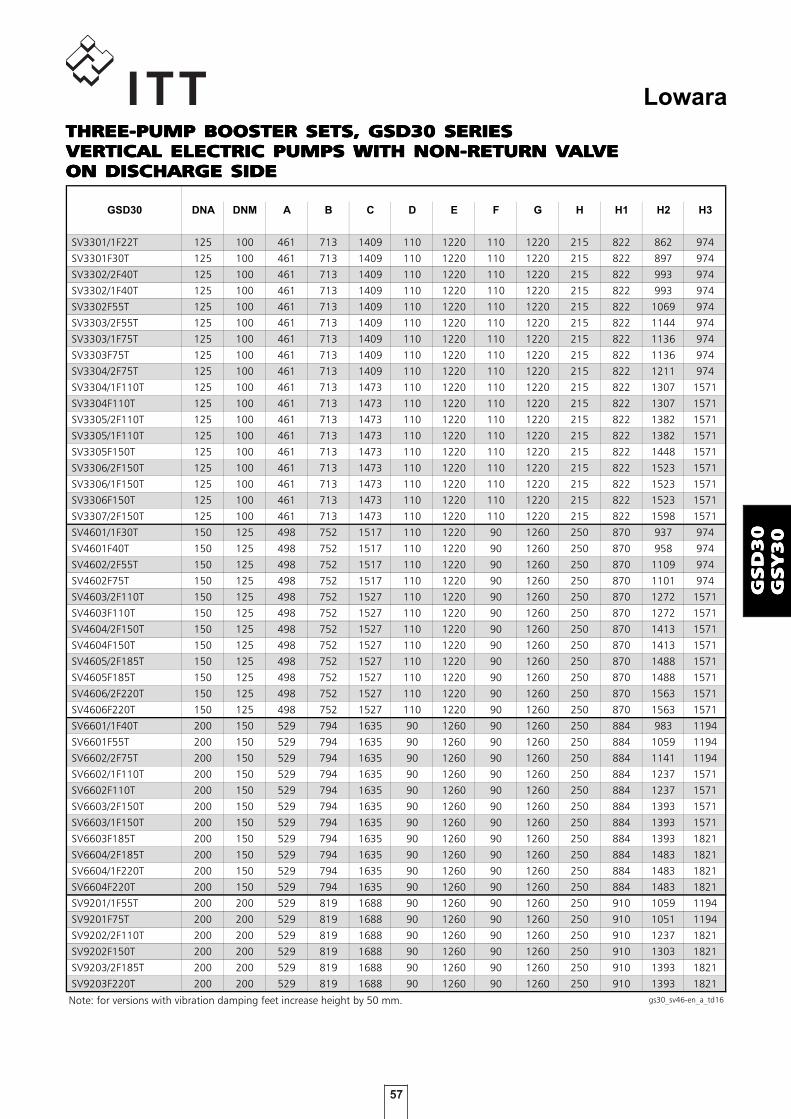
57
Lowara
GS
D3
0G
SD
30
GS
D3
0G
SD
30
GS
D3
0G
SY
30
GS
Y3
0G
SY
30
GS
Y3
0G
SY
30
THREE-PUMP BOOSTER SETS, GSD30 SERIESTHREE-PUMP BOOSTER SETS, GSD30 SERIESTHREE-PUMP BOOSTER SETS, GSD30 SERIESTHREE-PUMP BOOSTER SETS, GSD30 SERIESTHREE-PUMP BOOSTER SETS, GSD30 SERIESVERTICAL ELECTRIC PUMPS WITH NON-RETURN VVERTICAL ELECTRIC PUMPS WITH NON-RETURN VVERTICAL ELECTRIC PUMPS WITH NON-RETURN VVERTICAL ELECTRIC PUMPS WITH NON-RETURN VVERTICAL ELECTRIC PUMPS WITH NON-RETURN VALALALALALVEVEVEVEVEON DISCHARGE SIDEON DISCHARGE SIDEON DISCHARGE SIDEON DISCHARGE SIDEON DISCHARGE SIDE
GSD30 DNA DNM A B C D E F G H H1 H2 H3
SV3301/1F22T 125 100 461 713 1409 110 1220 110 1220 215 822 862 974
SV3301F30T 125 100 461 713 1409 110 1220 110 1220 215 822 897 974
SV3302/2F40T 125 100 461 713 1409 110 1220 110 1220 215 822 993 974
SV3302/1F40T 125 100 461 713 1409 110 1220 110 1220 215 822 993 974
SV3302F55T 125 100 461 713 1409 110 1220 110 1220 215 822 1069 974
SV3303/2F55T 125 100 461 713 1409 110 1220 110 1220 215 822 1144 974
SV3303/1F75T 125 100 461 713 1409 110 1220 110 1220 215 822 1136 974
SV3303F75T 125 100 461 713 1409 110 1220 110 1220 215 822 1136 974
SV3304/2F75T 125 100 461 713 1409 110 1220 110 1220 215 822 1211 974
SV3304/1F110T 125 100 461 713 1473 110 1220 110 1220 215 822 1307 1571
SV3304F110T 125 100 461 713 1473 110 1220 110 1220 215 822 1307 1571
SV3305/2F110T 125 100 461 713 1473 110 1220 110 1220 215 822 1382 1571
SV3305/1F110T 125 100 461 713 1473 110 1220 110 1220 215 822 1382 1571
SV3305F150T 125 100 461 713 1473 110 1220 110 1220 215 822 1448 1571
SV3306/2F150T 125 100 461 713 1473 110 1220 110 1220 215 822 1523 1571
SV3306/1F150T 125 100 461 713 1473 110 1220 110 1220 215 822 1523 1571
SV3306F150T 125 100 461 713 1473 110 1220 110 1220 215 822 1523 1571
SV3307/2F150T 125 100 461 713 1473 110 1220 110 1220 215 822 1598 1571
SV4601/1F30T 150 125 498 752 1517 110 1220 90 1260 250 870 937 974
SV4601F40T 150 125 498 752 1517 110 1220 90 1260 250 870 958 974
SV4602/2F55T 150 125 498 752 1517 110 1220 90 1260 250 870 1109 974
SV4602F75T 150 125 498 752 1517 110 1220 90 1260 250 870 1101 974
SV4603/2F110T 150 125 498 752 1527 110 1220 90 1260 250 870 1272 1571
SV4603F110T 150 125 498 752 1527 110 1220 90 1260 250 870 1272 1571
SV4604/2F150T 150 125 498 752 1527 110 1220 90 1260 250 870 1413 1571
SV4604F150T 150 125 498 752 1527 110 1220 90 1260 250 870 1413 1571
SV4605/2F185T 150 125 498 752 1527 110 1220 90 1260 250 870 1488 1571
SV4605F185T 150 125 498 752 1527 110 1220 90 1260 250 870 1488 1571
SV4606/2F220T 150 125 498 752 1527 110 1220 90 1260 250 870 1563 1571
SV4606F220T 150 125 498 752 1527 110 1220 90 1260 250 870 1563 1571
SV6601/1F40T 200 150 529 794 1635 90 1260 90 1260 250 884 983 1194
SV6601F55T 200 150 529 794 1635 90 1260 90 1260 250 884 1059 1194
SV6602/2F75T 200 150 529 794 1635 90 1260 90 1260 250 884 1141 1194
SV6602/1F110T 200 150 529 794 1635 90 1260 90 1260 250 884 1237 1571
SV6602F110T 200 150 529 794 1635 90 1260 90 1260 250 884 1237 1571
SV6603/2F150T 200 150 529 794 1635 90 1260 90 1260 250 884 1393 1571
SV6603/1F150T 200 150 529 794 1635 90 1260 90 1260 250 884 1393 1571
SV6603F185T 200 150 529 794 1635 90 1260 90 1260 250 884 1393 1821
SV6604/2F185T 200 150 529 794 1635 90 1260 90 1260 250 884 1483 1821
SV6604/1F220T 200 150 529 794 1635 90 1260 90 1260 250 884 1483 1821
SV6604F220T 200 150 529 794 1635 90 1260 90 1260 250 884 1483 1821
SV9201/1F55T 200 200 529 819 1688 90 1260 90 1260 250 910 1059 1194
SV9201F75T 200 200 529 819 1688 90 1260 90 1260 250 910 1051 1194
SV9202/2F110T 200 200 529 819 1688 90 1260 90 1260 250 910 1237 1821
SV9202F150T 200 200 529 819 1688 90 1260 90 1260 250 910 1303 1821
SV9203/2F185T 200 200 529 819 1688 90 1260 90 1260 250 910 1393 1821
SV9203F220T 200 200 529 819 1688 90 1260 90 1260 250 910 1393 1821
Note: for versions with vibration damping feet increase height by 50 mm. gs30_sv46-en_a_td16

58
Lowara
GS
D3
0G
SD
30
GS
D3
0G
SD
30
GS
D3
0G
SY
30
GS
Y3
0G
SY
30
GS
Y3
0G
SY
30
THREE-PUMP BOOSTER SETS, GSD30 RA SERIESTHREE-PUMP BOOSTER SETS, GSD30 RA SERIESTHREE-PUMP BOOSTER SETS, GSD30 RA SERIESTHREE-PUMP BOOSTER SETS, GSD30 RA SERIESTHREE-PUMP BOOSTER SETS, GSD30 RA SERIESVERTICAL ELECTRIC PUMPS WITH NON-RETURN VVERTICAL ELECTRIC PUMPS WITH NON-RETURN VVERTICAL ELECTRIC PUMPS WITH NON-RETURN VVERTICAL ELECTRIC PUMPS WITH NON-RETURN VVERTICAL ELECTRIC PUMPS WITH NON-RETURN VALALALALALVEVEVEVEVEON SUCTION SIDEON SUCTION SIDEON SUCTION SIDEON SUCTION SIDEON SUCTION SIDE

59
Lowara
GS
D3
0G
SD
30
GS
D3
0G
SD
30
GS
D3
0G
SY
30
GS
Y3
0G
SY
30
GS
Y3
0G
SY
30
THREE-PUMP BOOSTER SETS, GSD30 RA SERIESTHREE-PUMP BOOSTER SETS, GSD30 RA SERIESTHREE-PUMP BOOSTER SETS, GSD30 RA SERIESTHREE-PUMP BOOSTER SETS, GSD30 RA SERIESTHREE-PUMP BOOSTER SETS, GSD30 RA SERIESVERTICAL ELECTRIC PUMPS WITH NON-RETURN VVERTICAL ELECTRIC PUMPS WITH NON-RETURN VVERTICAL ELECTRIC PUMPS WITH NON-RETURN VVERTICAL ELECTRIC PUMPS WITH NON-RETURN VVERTICAL ELECTRIC PUMPS WITH NON-RETURN VALALALALALVEVEVEVEVEON SUCTION SIDEON SUCTION SIDEON SUCTION SIDEON SUCTION SIDEON SUCTION SIDE
GSD30RA DNA DNM A B C D E F G H H1 H2 H3
SV3301/1F22T 125 100 726 448 1409 110 1220 110 1220 215 822 862 974
SV3301F30T 125 100 726 448 1409 110 1220 110 1220 215 822 897 974
SV3302/2F40T 125 100 726 448 1409 110 1220 110 1220 215 822 993 974
SV3302/1F40T 125 100 726 448 1409 110 1220 110 1220 215 822 993 974
SV3302F55T 125 100 726 448 1409 110 1220 110 1220 215 822 1069 974
SV3303/2F55T 125 100 726 448 1409 110 1220 110 1220 215 822 1144 974
SV3303/1F75T 125 100 726 448 1409 110 1220 110 1220 215 822 1136 974
SV3303F75T 125 100 726 448 1409 110 1220 110 1220 215 822 1136 974
SV3304/2F75T 125 100 726 448 1409 110 1220 110 1220 215 822 1211 974
SV3304/1F110T 125 100 726 448 1409 110 1220 110 1220 215 822 1307 1571
SV3304F110T 125 100 726 448 1409 110 1220 110 1220 215 822 1307 1571
SV3305/2F110T 125 100 726 448 1409 110 1220 110 1220 215 822 1382 1571
SV3305/1F110T 125 100 726 448 1409 110 1220 110 1220 215 822 1382 1571
SV3305F150T 125 100 726 448 1409 110 1220 110 1220 215 822 1448 1571
SV3306/2F150T 125 100 726 448 1409 110 1220 110 1220 215 822 1523 1571
SV3306/1F150T 125 100 726 448 1409 110 1220 110 1220 215 822 1523 1571
SV3306F150T 125 100 726 448 1409 110 1220 110 1220 215 822 1523 1571
SV3307/2F150T 125 100 726 448 1409 110 1220 110 1220 215 822 1598 1571
SV4601/1F30T 150 125 766 484 1517 110 1220 90 1260 250 870 937 974
SV4601F40T 150 125 766 484 1517 110 1220 90 1260 250 870 958 974
SV4602/2F55T 150 125 766 484 1517 110 1220 90 1260 250 870 1109 974
SV4602F75T 150 125 766 484 1517 110 1220 90 1260 250 870 1101 974
SV4603/2F110T 150 125 766 484 1517 110 1220 90 1260 250 870 1272 1571
SV4603F110T 150 125 766 484 1517 110 1220 90 1260 250 870 1272 1571
SV4604/2F150T 150 125 766 484 1517 110 1220 90 1260 250 870 1413 1571
SV4604F150T 150 125 766 484 1517 110 1220 90 1260 250 870 1413 1571
SV4605/2F185T 150 125 766 484 1517 110 1220 90 1260 250 870 1488 1571
SV4605F185T 150 125 766 484 1517 110 1220 90 1260 250 870 1488 1571
SV4606/2F220T 150 125 766 484 1517 110 1220 90 1260 250 870 1563 1571
SV4606F220T 150 125 766 484 1517 110 1220 90 1260 250 870 1563 1571
SV6601/1F40T 200 150 819 504 1635 90 1260 90 1260 250 884 983 1194
SV6601F55T 200 150 819 504 1635 90 1260 90 1260 250 884 1059 1194
SV6602/2F75T 200 150 819 504 1635 90 1260 90 1260 250 884 1141 1194
SV6602/1F110T 200 150 819 504 1635 90 1260 90 1260 250 884 1237 1571
SV6602F110T 200 150 819 504 1635 90 1260 90 1260 250 884 1237 1571
SV6603/2F150T 200 150 819 504 1635 90 1260 90 1260 250 884 1393 1571
SV6603/1F150T 200 150 819 504 1635 90 1260 90 1260 250 884 1393 1571
SV6603F185T 200 150 819 504 1635 90 1260 90 1260 250 884 1393 1821
SV6604/2F185T 200 150 819 504 1635 90 1260 90 1260 250 884 1483 1821
SV6604/1F220T 200 150 819 504 1635 90 1260 90 1260 250 884 1483 1821
SV6604F220T 200 150 819 504 1635 90 1260 90 1260 250 884 1483 1821
SV9201/1F55T 200 200 819 529 1688 90 1260 90 1260 250 910 1059 1194
SV9201F75T 200 200 819 529 1688 90 1260 90 1260 250 910 1051 1194
SV9202/2F110T 200 200 819 529 1688 90 1260 90 1260 250 910 1237 1821
SV9202F150T 200 200 819 529 1688 90 1260 90 1260 250 910 1303 1821
SV9203/2F185T 200 200 819 529 1688 90 1260 90 1260 250 910 1393 1821
SV9203F220T 200 200 819 529 1688 90 1260 90 1260 250 910 1393 1821
Note: for versions with vibration damping feet increase height by 50 mm. gs30ra_sv46-en_a_td16

60
Lowara
GS
D3
0G
SD
30
GS
D3
0G
SD
30
GS
D3
0G
SY
30
GS
Y3
0G
SY
30
GS
Y3
0G
SY
30
GSY30 DNA DNM A B C H1 H2
SV6605/2F300T 200 150 529 794 1635 914 1722
SV6605/1F300T 200 150 529 794 1635 914 1722
SV6605F300T 200 150 529 794 1635 914 1722
SV9204/2F300T 200 200 529 819 1688 940 1632
SV9204F300T 200 200 529 819 1688 940 1632
SV9205/2F370T 200 200 529 819 1688 940 1722
Note: for versions with vibration damping feet increase height by 50 mm. gs30_sv-big-en_a_td
THREE-PUMP BOOSTER SETS, GSY30 SERIESTHREE-PUMP BOOSTER SETS, GSY30 SERIESTHREE-PUMP BOOSTER SETS, GSY30 SERIESTHREE-PUMP BOOSTER SETS, GSY30 SERIESTHREE-PUMP BOOSTER SETS, GSY30 SERIESVERTICAL ELECTRIC PUMPS WITH NON-RETURN VVERTICAL ELECTRIC PUMPS WITH NON-RETURN VVERTICAL ELECTRIC PUMPS WITH NON-RETURN VVERTICAL ELECTRIC PUMPS WITH NON-RETURN VVERTICAL ELECTRIC PUMPS WITH NON-RETURN VALALALALALVEVEVEVEVEON DISCHARGE SIDEON DISCHARGE SIDEON DISCHARGE SIDEON DISCHARGE SIDEON DISCHARGE SIDE

61
Lowara
GS
D3
0G
SD
30
GS
D3
0G
SD
30
GS
D3
0G
SY
30
GS
Y3
0G
SY
30
GS
Y3
0G
SY
30
GSY30RA DNA DNM A B C H1 H2
SV6605/2F300T 200 150 819 504 1635 914 1722
SV6605/1F300T 200 150 819 504 1635 914 1722
SV6605F300T 200 150 819 504 1635 914 1722
SV9204/2F300T 200 200 819 529 1688 940 1632
SV9204F300T 200 200 819 529 1688 940 1632
SV9205/2F370T 200 200 819 529 1688 940 1722
Note: for versions with vibration damping feet increase height by 50 mm. gs30ra_sv-big-en_a_td
THREE-PUMP BOOSTER SETS, GSY30 RA SERIESTHREE-PUMP BOOSTER SETS, GSY30 RA SERIESTHREE-PUMP BOOSTER SETS, GSY30 RA SERIESTHREE-PUMP BOOSTER SETS, GSY30 RA SERIESTHREE-PUMP BOOSTER SETS, GSY30 RA SERIESVERTICAL ELECTRIC PUMPS WITH NON-RETURN VVERTICAL ELECTRIC PUMPS WITH NON-RETURN VVERTICAL ELECTRIC PUMPS WITH NON-RETURN VVERTICAL ELECTRIC PUMPS WITH NON-RETURN VVERTICAL ELECTRIC PUMPS WITH NON-RETURN VALALALALALVEVEVEVEVEON SUCTION SIDEON SUCTION SIDEON SUCTION SIDEON SUCTION SIDEON SUCTION SIDE

62
Lowara
CU
RV
ES
CU
RV
ES
CU
RV
ES
CU
RV
ES
CU
RV
ES
Pp
[kW
]
0,04
0,08
0,12
η [%
]
30
50
70
0 1 2 3 4 5
NP
SH
[m]
0
2
4
6
0 10 20 30 40 50 60 70 80
NP
SH
[ft]
05
1015
H [m
]
0
20
40
60
80
100
120
140
160
180
2000 5 10 15 20
H [f
t]
0
100
200
300
400
500
600
0 5 10 15
7692
8_C
_CH
ISO 9906 - Annex A
Q [US gpm]
Q [Imp gpm]
Q [l/min]
Q [m3/h]
∼ 2900 [rpm]
η
14
12
1110
16
kW/stage
19
21
13
3SV02..3SV21
05
02
0304
06
0708
09
BOOSTER SETS,BOOSTER SETS,BOOSTER SETS,BOOSTER SETS,BOOSTER SETS, GS.../SV GS.../SV GS.../SV GS.../SV GS.../SV SERIESSERIESSERIESSERIESSERIESOPERAOPERAOPERAOPERAOPERATING CHARACTERISTICTING CHARACTERISTICTING CHARACTERISTICTING CHARACTERISTICTING CHARACTERISTICS AS AS AS AS AT 50 Hz (JOCKEY PUMP)T 50 Hz (JOCKEY PUMP)T 50 Hz (JOCKEY PUMP)T 50 Hz (JOCKEY PUMP)T 50 Hz (JOCKEY PUMP)
The performance curves do not take into account flow resistance in the valves and piping.The curves show performance with one pump running.These performances are valid for liquids with density ρ = 1.0 kg/dm³ and kinematic viscosity ν = 1 mm²/s.

63
Lowara
CU
RV
ES
CU
RV
ES
CU
RV
ES
CU
RV
ES
CU
RV
ES
H [m
]
2
4
6
8
10
12
140 50 100 150 200
H [f
t]
10
20
30
40
0 50 100 150
0 10 20 30 40 50
NP
SH
[m]
1
2
3
0 200 400 600 800
NP
SH
[ft]
0
2
4
6
8
7681
1_A
_CH
10SV01 ∼ 2850 [rpm] ISO 9906 - Annex A
1 P 2 P 3 P
Q [Imp gpm]
Q [US gpm]
Q [m3/h]
Q [l/min]
H [m
]
5
10
15
20
250 50 100 150 200
H [f
t]
20
30
40
50
60
70
80
0 50 100 150
0 10 20 30 40 50
NP
SH
[m]
1
2
3
0 200 400 600 800
NP
SH
[ft]
0
2
4
6
8
7681
2_A
_CH
10SV02 ∼ 2850 [rpm] ISO 9906 - Annex A
1 P 2 P 3 P
Q [Imp gpm]
Q [US gpm]
Q [m3/h]
Q [l/min]
H [m
]
10
20
30
400 50 100 150 200
H [f
t]
40
60
80
100
120
0 50 100 150
0 10 20 30 40 50
NP
SH
[m]
1
2
3
0 200 400 600 800
NP
SH
[ft]
0
2
4
6
8
7681
3_A
_CH
10SV03 ∼ 2850 [rpm] ISO 9906 - Annex A
1 P 2 P 3 P
Q [Imp gpm]
Q [US gpm]
Q [m3/h]
Q [l/min]
H [m
]
10
20
30
40
500 50 100 150 200
H [f
t]
40
60
80
100
120
140
160
0 50 100 150
0 10 20 30 40 50
NP
SH
[m]
1
2
3
0 200 400 600 800
NP
SH
[ft]
0
2
4
6
8
7681
4_A
_CH
10SV04 ∼ 2850 [rpm] ISO 9906 - Annex A
1 P 2 P 3 P
Q [Imp gpm]
Q [US gpm]
Q [m3/h]
Q [l/min]
BOOSTER SETS,BOOSTER SETS,BOOSTER SETS,BOOSTER SETS,BOOSTER SETS, GS.../SV GS.../SV GS.../SV GS.../SV GS.../SV SERIESSERIESSERIESSERIESSERIESOPERAOPERAOPERAOPERAOPERATING CHARACTERISTICTING CHARACTERISTICTING CHARACTERISTICTING CHARACTERISTICTING CHARACTERISTICS AS AS AS AS AT 50 Hz (SERVICE PUMP)T 50 Hz (SERVICE PUMP)T 50 Hz (SERVICE PUMP)T 50 Hz (SERVICE PUMP)T 50 Hz (SERVICE PUMP)
The performance curves do not take into account flow resistance in the valves and piping.The curves show the performance with one, two and three pumps running.These performances are valid for liquids with density ρ = 1.0 Kg/dm3 and kinematic viscosity ν = 1 mm2/s.The declared NPSH values are laboratory values: for practical use we recommend increasing these values by 0.5 m.

64
Lowara
CU
RV
ES
CU
RV
ES
CU
RV
ES
CU
RV
ES
CU
RV
ES H
[m]
20
40
60
80
1000 50 100 150 200
H [f
t]
100
150
200
250
300
0 50 100 150
0 10 20 30 40 50
NP
SH
[m]
1
2
3
0 200 400 600 800
NP
SH
[ft]
0
2
4
6
8
7681
8_A
_CH
10SV08 ∼ 2850 [rpm] ISO 9906 - Annex A
1 P 2 P 3 P
Q [Imp gpm]
Q [US gpm]
Q [m3/h]
Q [l/min]
H [m
]
10
20
30
40
50
60
700 50 100 150 200
H [f
t]
50
100
150
200
0 50 100 150
0 10 20 30 40 50
NP
SH
[m]
1
2
3
0 200 400 600 800
NP
SH
[ft]
0
2
4
6
8
7681
5_A
_CH
10SV05 ∼ 2850 [rpm] ISO 9906 - Annex A
1 P 2 P 3 P
Q [Imp gpm]
Q [US gpm]
Q [m3/h]
Q [l/min]
H [m
]
30
45
60
75
0 50 100 150 200
H [f
t]
100
150
200
250
0 50 100 150
0 10 20 30 40 50
NP
SH
[m]
1
2
3
0 200 400 600 800
NP
SH
[ft]
0
2
4
6
8
7681
6_A
_CH
10SV06 ∼ 2850 [rpm] ISO 9906 - Annex A
1 P 2 P 3 P
Q [Imp gpm]
Q [US gpm]
Q [m3/h]
Q [l/min]
H [m
]
30
45
60
75
900 50 100 150 200
H [f
t]
100
150
200
250
0 50 100 150
0 10 20 30 40 50
NP
SH
[m]
1
2
3
0 200 400 600 800
NP
SH
[ft]
0
2
4
6
8
7681
7_A
_CH
10SV07 ∼ 2850 [rpm] ISO 9906 - Annex A
1 P 2 P 3 P
Q [Imp gpm]
Q [US gpm]
Q [m3/h]
Q [l/min]
BOOSTER SETS,BOOSTER SETS,BOOSTER SETS,BOOSTER SETS,BOOSTER SETS, GS.../SV GS.../SV GS.../SV GS.../SV GS.../SV SERIESSERIESSERIESSERIESSERIESOPERAOPERAOPERAOPERAOPERATING CHARACTERISTICTING CHARACTERISTICTING CHARACTERISTICTING CHARACTERISTICTING CHARACTERISTICS AS AS AS AS AT 50 Hz (SERVICE PUMP)T 50 Hz (SERVICE PUMP)T 50 Hz (SERVICE PUMP)T 50 Hz (SERVICE PUMP)T 50 Hz (SERVICE PUMP)
The performance curves do not take into account flow resistance in the valves and piping.The curves show the performance with one, two and three pumps running.These performances are valid for liquids with density ρ = 1.0 Kg/dm3 and kinematic viscosity ν = 1 mm2/s.The declared NPSH values are laboratory values: for practical use we recommend increasing these values by 0.5 m.

65
Lowara
CU
RV
ES
CU
RV
ES
CU
RV
ES
CU
RV
ES
CU
RV
ES
H [m
]
20
40
60
80
100
1200 50 100 150 200
H [f
t]
100
200
300
0 50 100 150
0 10 20 30 40 50
NP
SH
[m]
1
2
3
0 200 400 600 800
NP
SH
[ft]
0
2
4
6
8
7681
9_A
_CH
10SV09 ∼ 2850 [rpm] ISO 9906 - Annex A
1 P 2 P 3 P
Q [Imp gpm]
Q [US gpm]
Q [m3/h]
Q [l/min]
H [m
]
20
40
60
80
100
120
1400 50 100 150 200
H [f
t]
100
200
300
400
0 50 100 150
0 10 20 30 40 50
NP
SH
[m]
1
2
3
0 200 400 600 800
NP
SH
[ft]
0
2
4
6
8
7682
0_A
_CH
10SV10 ∼ 2850 [rpm] ISO 9906 - Annex A
1 P 2 P 3 P
Q [Imp gpm]
Q [US gpm]
Q [m3/h]
Q [l/min]
H [m
]
20
40
60
80
100
120
1400 50 100 150 200
H [f
t]
100
200
300
400
0 50 100 150
0 10 20 30 40 50
NP
SH
[m]
1
2
3
0 200 400 600 800
NP
SH
[ft]
0
2
4
6
8
7682
1_A
_CH
10SV11 ∼ 2850 [rpm] ISO 9906 - Annex A
1 P 2 P 3 P
Q [Imp gpm]
Q [US gpm]
Q [m3/h]
Q [l/min]
H [m
]
25
50
75
100
125
150
1750 50 100 150 200
H [f
t]
100
200
300
400
500
0 50 100 150
0 10 20 30 40 50
NP
SH
[m]
1
2
3
0 200 400 600 800
NP
SH
[ft]
0
2
4
6
8
7682
2_A
_CH
10SV13 ∼ 2850 [rpm] ISO 9906 - Annex A
1 P 2 P 3 P
Q [Imp gpm]
Q [US gpm]
Q [m3/h]
Q [l/min]
BOOSTER SETS,BOOSTER SETS,BOOSTER SETS,BOOSTER SETS,BOOSTER SETS, GS.../SV GS.../SV GS.../SV GS.../SV GS.../SV SERIESSERIESSERIESSERIESSERIESOPERAOPERAOPERAOPERAOPERATING CHARACTERISTICTING CHARACTERISTICTING CHARACTERISTICTING CHARACTERISTICTING CHARACTERISTICS AS AS AS AS AT 50 Hz (SERVICE PUMP)T 50 Hz (SERVICE PUMP)T 50 Hz (SERVICE PUMP)T 50 Hz (SERVICE PUMP)T 50 Hz (SERVICE PUMP)
The performance curves do not take into account flow resistance in the valves and piping.The curves show the performance with one, two and three pumps running.These performances are valid for liquids with density ρ = 1.0 Kg/dm3 and kinematic viscosity ν = 1 mm2/s.The declared NPSH values are laboratory values: for practical use we recommend increasing these values by 0.5 m.

66
Lowara
CU
RV
ES
CU
RV
ES
CU
RV
ES
CU
RV
ES
CU
RV
ES
H [m
]
4
6
8
10
12
14
160 50 100 150 200 250 300 350
H [f
t]
20
30
40
50
0 50 100 150 200 250
0 20 40 60 80
NP
SH
[m]
0
2
4
6
0 200 400 600 800 1000 1200
NP
SH
[ft]
0
5
10
15
7682
3_A
_CH
15SV01 ∼ 2850 [rpm] ISO 9906 - Annex A
1 P 2 P 3 P
Q [Imp gpm]
Q [US gpm]
Q [m3/h]
Q [l/min]
H [m
]
10
15
20
25
300 50 100 150 200 250 300 350
H [f
t]
40
60
80
0 50 100 150 200 250
0 20 40 60 80
NP
SH
[m]
0
2
4
6
0 200 400 600 800 1000 1200
NP
SH
[ft]
0
5
10
15
7682
4_A
_CH
15SV02 ∼ 2850 [rpm] ISO 9906 - Annex A
1 P 2 P 3 P
Q [Imp gpm]
Q [US gpm]
Q [m3/h]
Q [l/min]
H [m
]
10
20
30
40
500 50 100 150 200 250 300 350
H [f
t]
40
60
80
100
120
140
160
0 50 100 150 200 250
0 20 40 60 80
NP
SH
[m]
0
2
4
6
0 200 400 600 800 1000 1200
NP
SH
[ft]
0
5
10
15
7682
5_A
_CH
15SV03 ∼ 2850 [rpm] ISO 9906 - Annex A
1 P 2 P 3 P
Q [Imp gpm]
Q [US gpm]
Q [m3/h]
Q [l/min]
H [m
]
15
30
45
60
750 50 100 150 200 250 300 350
H [f
t]
50
100
150
200
0 50 100 150 200 250
0 20 40 60 80
NP
SH
[m]
0
2
4
6
0 200 400 600 800 1000 1200
NP
SH
[ft]
0
5
10
15
7682
6_A
_CH
15SV04 ∼ 2850 [rpm] ISO 9906 - Annex A
1 P 2 P 3 P
Q [Imp gpm]
Q [US gpm]
Q [m3/h]
Q [l/min]
BOOSTER SETS,BOOSTER SETS,BOOSTER SETS,BOOSTER SETS,BOOSTER SETS, GS.../SV GS.../SV GS.../SV GS.../SV GS.../SV SERIESSERIESSERIESSERIESSERIESOPERAOPERAOPERAOPERAOPERATING CHARACTERISTICTING CHARACTERISTICTING CHARACTERISTICTING CHARACTERISTICTING CHARACTERISTICS AS AS AS AS AT 50 Hz (SERVICE PUMP)T 50 Hz (SERVICE PUMP)T 50 Hz (SERVICE PUMP)T 50 Hz (SERVICE PUMP)T 50 Hz (SERVICE PUMP)
The performance curves do not take into account flow resistance in the valves and piping.The curves show the performance with one, two and three pumps running.These performances are valid for liquids with density ρ = 1.0 Kg/dm3 and kinematic viscosity ν = 1 mm2/s.The declared NPSH values are laboratory values: for practical use we recommend increasing these values by 0.5 m.

67
Lowara
CU
RV
ES
CU
RV
ES
CU
RV
ES
CU
RV
ES
CU
RV
ES
H [m
]
15
30
45
60
75
900 50 100 150 200 250 300 350
H [f
t]
50
100
150
200
250
0 50 100 150 200 250
0 20 40 60 80
NP
SH
[m]
0
2
4
6
0 200 400 600 800 1000 1200
NP
SH
[ft]
0
5
10
15
7682
7_A
_CH
15SV05 ∼ 2850 [rpm] ISO 9906 - Annex A
1 P 2 P 3 P
Q [Imp gpm]
Q [US gpm]
Q [m3/h]
Q [l/min]
H [m
]
20
40
60
80
1000 50 100 150 200 250 300 350
H [f
t]
100
150
200
250
300
0 50 100 150 200 250
0 20 40 60 80
NP
SH
[m]
0
2
4
6
0 200 400 600 800 1000 1200
NP
SH
[ft]
0
5
10
15
7682
8_A
_CH
15SV06 ∼ 2850 [rpm] ISO 9906 - Annex A
1 P 2 P 3 P
Q [Imp gpm]
Q [US gpm]
Q [m3/h]
Q [l/min]
H [m
]
20
40
60
80
100
1200 50 100 150 200 250 300 350
H [f
t]
100
200
300
0 50 100 150 200 250
0 20 40 60 80
NP
SH
[m]
0
2
4
6
0 200 400 600 800 1000 1200
NP
SH
[ft]
0
5
10
15
7682
9_A
_CH
15SV07 ∼ 2850 [rpm] ISO 9906 - Annex A
1 P 2 P 3 P
Q [Imp gpm]
Q [US gpm]
Q [m3/h]
Q [l/min]
H [m
]
40
60
80
100
120
1400 50 100 150 200 250 300 350
H [f
t]
150
200
250
300
350
400
450
0 50 100 150 200 250
0 20 40 60 80
NP
SH
[m]
0
2
4
6
0 200 400 600 800 1000 1200
NP
SH
[ft]
0
5
10
15
7683
0_A
_CH
15SV08 ∼ 2850 [rpm] ISO 9906 - Annex A
1 P 2 P 3 P
Q [Imp gpm]
Q [US gpm]
Q [m3/h]
Q [l/min]
BOOSTER SETS,BOOSTER SETS,BOOSTER SETS,BOOSTER SETS,BOOSTER SETS, GS.../SV GS.../SV GS.../SV GS.../SV GS.../SV SERIESSERIESSERIESSERIESSERIESOPERAOPERAOPERAOPERAOPERATING CHARACTERISTICTING CHARACTERISTICTING CHARACTERISTICTING CHARACTERISTICTING CHARACTERISTICS AS AS AS AS AT 50 Hz (SERVICE PUMP)T 50 Hz (SERVICE PUMP)T 50 Hz (SERVICE PUMP)T 50 Hz (SERVICE PUMP)T 50 Hz (SERVICE PUMP)
The performance curves do not take into account flow resistance in the valves and piping.The curves show the performance with one, two and three pumps running.These performances are valid for liquids with density ρ = 1.0 Kg/dm3 and kinematic viscosity ν = 1 mm2/s.The declared NPSH values are laboratory values: for practical use we recommend increasing these values by 0.5 m.

68
Lowara
CU
RV
ES
CU
RV
ES
CU
RV
ES
CU
RV
ES
CU
RV
ES
H [m
]
40
60
80
100
120
1400 50 100 150 200 250 300 350
H [f
t]
150
200
250
300
350
400
450
0 50 100 150 200 250
0 20 40 60 80
NP
SH
[m]
0
2
4
6
0 200 400 600 800 1000 1200
NP
SH
[ft]
0
5
10
15
7683
1_A
_CH
15SV09 ∼ 2850 [rpm] ISO 9906 - Annex A
1 P 2 P 3 P
Q [Imp gpm]
Q [US gpm]
Q [m3/h]
Q [l/min]
H [m
]
40
60
80
100
120
140
1600 50 100 150 200 250 300 350
H [f
t]
200
300
400
500
0 50 100 150 200 250
0 20 40 60 80
NP
SH
[m]
0
2
4
6
0 200 400 600 800 1000 1200
NP
SH
[ft]
0
5
10
15
7683
2_A
_CH
15SV10 ∼ 2850 [rpm] ISO 9906 - Annex A
1 P 2 P 3 P
Q [Imp gpm]
Q [US gpm]
Q [m3/h]
Q [l/min]
H [m
]
2
4
6
8
10
12
14
160 100 200 300 400
H [f
t]
10
20
30
40
50
0 100 200 300
0 20 40 60 80 100
NP
SH
[m]
0
2
4
6
0 200 400 600 800 1000 1200 1400 1600
NP
SH
[ft]
0
5
10
15
7683
3_A
_CH
22SV01 ∼ 2850 [rpm] ISO 9906 - Annex A
1 P 2 P 3 P
Q [Imp gpm]
Q [US gpm]
Q [m3/h]
Q [l/min]
H [m
]
10
20
30
400 100 200 300 400
H [f
t]
40
60
80
100
120
0 100 200 300
0 20 40 60 80 100
NP
SH
[m]
0
2
4
6
0 200 400 600 800 1000 1200 1400 1600
NP
SH
[ft]
0
5
10
15
7683
4_A
_CH
22SV02 ∼ 2850 [rpm] ISO 9906 - Annex A
1 P 2 P 3 P
Q [Imp gpm]
Q [US gpm]
Q [m3/h]
Q [l/min]
BOOSTER SETS,BOOSTER SETS,BOOSTER SETS,BOOSTER SETS,BOOSTER SETS, GS.../SV GS.../SV GS.../SV GS.../SV GS.../SV SERIESSERIESSERIESSERIESSERIESOPERAOPERAOPERAOPERAOPERATING CHARACTERISTICTING CHARACTERISTICTING CHARACTERISTICTING CHARACTERISTICTING CHARACTERISTICS AS AS AS AS AT 50 Hz (SERVICE PUMP)T 50 Hz (SERVICE PUMP)T 50 Hz (SERVICE PUMP)T 50 Hz (SERVICE PUMP)T 50 Hz (SERVICE PUMP)
The performance curves do not take into account flow resistance in the valves and piping.The curves show the performance with one, two and three pumps running.These performances are valid for liquids with density ρ = 1.0 Kg/dm3 and kinematic viscosity ν = 1 mm2/s.The declared NPSH values are laboratory values: for practical use we recommend increasing these values by 0.5 m.

69
Lowara
CU
RV
ES
CU
RV
ES
CU
RV
ES
CU
RV
ES
CU
RV
ES
H [m
]
10
20
30
40
500 100 200 300 400
H [f
t]
40
60
80
100
120
140
160
0 100 200 300
0 20 40 60 80 100
NP
SH
[m]
0
2
4
6
0 200 400 600 800 1000 1200 1400 1600
NP
SH
[ft]
0
5
10
15
7683
5_A
_CH
22SV03 ∼ 2850 [rpm] ISO 9906 - Annex A
1 P 2 P 3 P
Q [Imp gpm]
Q [US gpm]
Q [m3/h]
Q [l/min]
H [m
]15
30
45
60
750 100 200 300 400
H [f
t]
50
100
150
200
0 100 200 300
0 20 40 60 80 100
NP
SH
[m]
0
2
4
6
0 200 400 600 800 1000 1200 1400 1600
NP
SH
[ft]
0
5
10
15
7683
6_A
_CH
22SV04 ∼ 2850 [rpm] ISO 9906 - Annex A
1 P 2 P 3 P
Q [Imp gpm]
Q [US gpm]
Q [m3/h]
Q [l/min]
H [m
]
15
30
45
60
75
900 100 200 300 400
H [f
t]
50
100
150
200
250
0 100 200 300
0 20 40 60 80 100
NP
SH
[m]
0
2
4
6
0 200 400 600 800 1000 1200 1400 1600
NP
SH
[ft]
0
5
10
15
7683
7_A
_CH
22SV05 ∼ 2850 [rpm] ISO 9906 - Annex A
1 P 2 P 3 P
Q [Imp gpm]
Q [US gpm]
Q [m3/h]
Q [l/min]
H [m
]
15
30
45
60
75
90
1050 100 200 300 400
H [f
t]
50
100
150
200
250
300
0 100 200 300
0 20 40 60 80 100
NP
SH
[m]
0
2
4
6
0 200 400 600 800 1000 1200 1400 1600
NP
SH
[ft]
0
5
10
15
7683
8_A
_CH
22SV06 ∼ 2850 [rpm] ISO 9906 - Annex A
1 P 2 P 3 P
Q [Imp gpm]
Q [US gpm]
Q [m3/h]
Q [l/min]
BOOSTER SETS,BOOSTER SETS,BOOSTER SETS,BOOSTER SETS,BOOSTER SETS, GS.../SV GS.../SV GS.../SV GS.../SV GS.../SV SERIESSERIESSERIESSERIESSERIESOPERAOPERAOPERAOPERAOPERATING CHARACTERISTICTING CHARACTERISTICTING CHARACTERISTICTING CHARACTERISTICTING CHARACTERISTICS AS AS AS AS AT 50 Hz (SERVICE PUMP)T 50 Hz (SERVICE PUMP)T 50 Hz (SERVICE PUMP)T 50 Hz (SERVICE PUMP)T 50 Hz (SERVICE PUMP)
The performance curves do not take into account flow resistance in the valves and piping.The curves show the performance with one, two and three pumps running.These performances are valid for liquids with density ρ = 1.0 Kg/dm3 and kinematic viscosity ν = 1 mm2/s.The declared NPSH values are laboratory values: for practical use we recommend increasing these values by 0.5 m.

70
Lowara
CU
RV
ES
CU
RV
ES
CU
RV
ES
CU
RV
ES
CU
RV
ES
H [m
]
20
40
60
80
100
1200 100 200 300 400
H [f
t]
100
200
300
0 100 200 300
0 20 40 60 80 100
NP
SH
[m]
0
2
4
6
0 200 400 600 800 1000 1200 1400 1600
NP
SH
[ft]
0
5
10
15
7683
9_A
_CH
22SV07 ∼ 2850 [rpm] ISO 9906 - Annex A
1 P 2 P 3 P
Q [Imp gpm]
Q [US gpm]
Q [m3/h]
Q [l/min]
H [m
]
40
60
80
100
120
1400 100 200 300 400
H [f
t]
150
200
250
300
350
400
450
0 100 200 300
0 20 40 60 80 100
NP
SH
[m]
0
2
4
6
0 200 400 600 800 1000 1200 1400 1600
NP
SH
[ft]
0
5
10
15
7684
0_A
_CH
22SV08 ∼ 2850 [rpm] ISO 9906 - Annex A
1 P 2 P 3 P
Q [Imp gpm]
Q [US gpm]
Q [m3/h]
Q [l/min]
H [m
]
40
60
80
100
120
140
1600 100 200 300 400
H [f
t]
200
300
400
500
0 100 200 300
0 20 40 60 80 100
NP
SH
[m]
0
2
4
6
0 200 400 600 800 1000 1200 1400 1600
NP
SH
[ft]
0
5
10
15
7684
1_A
_CH
22SV09 ∼ 2850 [rpm] ISO 9906 - Annex A
1 P 2 P 3 P
Q [Imp gpm]
Q [US gpm]
Q [m3/h]
Q [l/min]
H [m
]
60
80
100
120
140
160
1800 100 200 300 400
H [f
t]
200
300
400
500
0 100 200 300
0 20 40 60 80 100
NP
SH
[m]
0
2
4
6
0 200 400 600 800 1000 1200 1400 1600
NP
SH
[ft]
0
5
10
15
7684
2_A
_CH
22SV10 ∼ 2850 [rpm] ISO 9906 - Annex A
1 P 2 P 3 P
Q [Imp gpm]
Q [US gpm]
Q [m3/h]
Q [l/min]
BOOSTER SETS,BOOSTER SETS,BOOSTER SETS,BOOSTER SETS,BOOSTER SETS, GS.../SV GS.../SV GS.../SV GS.../SV GS.../SV SERIESSERIESSERIESSERIESSERIESOPERAOPERAOPERAOPERAOPERATING CHARACTERISTICTING CHARACTERISTICTING CHARACTERISTICTING CHARACTERISTICTING CHARACTERISTICS AS AS AS AS AT 50 Hz (SERVICE PUMP)T 50 Hz (SERVICE PUMP)T 50 Hz (SERVICE PUMP)T 50 Hz (SERVICE PUMP)T 50 Hz (SERVICE PUMP)
The performance curves do not take into account flow resistance in the valves and piping.The curves show the performance with one, two and three pumps running.These performances are valid for liquids with density ρ = 1.0 Kg/dm3 and kinematic viscosity ν = 1 mm2/s.The declared NPSH values are laboratory values: for practical use we recommend increasing these values by 0.5 m.

71
Lowara
CU
RV
ES
CU
RV
ES
CU
RV
ES
CU
RV
ES
CU
RV
ES
H [m
]
0
5
10
15
20
25
30
35
40
Q [US gpm]0 100 200 300 400 500 600
H [f
t]
0
20
40
60
80
100
120
Q [Imp gpm]0 100 200 300 400 500
0 20 40 60 80 100 120 140
NP
SH
[m]
0
5
10
15
Q [l/min]0 500 1000 1500 2000
NP
SH
[ft]
0
10
20
30
40
7501
7_B
_CH
SV3302/2 ISO 9906 - Annex A
1 P 2 P 3 P
Q [m3/h]
∼ 2900 [rpm]
H [m
]
5
10
15
20
25
30
35
40
45
Q [US gpm]0 100 200 300 400 500 600
H [f
t]
20
40
60
80
100
120
140
Q [Imp gpm]0 100 200 300 400 500
0 20 40 60 80 100 120 140
NP
SH
[m]
0
5
10
15
Q [l/min]0 500 1000 1500 2000
NP
SH
[ft]
0
10
20
30
40
7501
8_B
_CH
SV3302/1 ISO 9906 - Annex A
1 P 2 P 3 P
Q [m3/h]
∼ 2900 [rpm]
H [m
]
0
5
10
15
20
25
Q [US gpm]0 100 200 300 400 500 600
H [f
t]
0
20
40
60
80
Q [Imp gpm]0 100 200 300 400 500
0 20 40 60 80 100 120 140
NP
SH
[m]
0
5
10
15
Q [l/min]0 500 1000 1500 2000
NP
SH
[ft]
0
10
20
30
40
7501
6_B
_CH
SV3301 ISO 9906 - Annex A
1 P 2 P 3 P
Q [m3/h]
∼ 2900 [rpm]
H [m
]
0
2
4
6
8
10
12
14
16
18
20
Q [US gpm]0 100 200 300 400 500 600
H [f
t]
0
10
20
30
40
50
60
Q [Imp gpm]0 100 200 300 400 500
0 20 40 60 80 100 120 140
NP
SH
[m]
0
5
10
15
Q [l/min]0 500 1000 1500 2000
NP
SH
[ft]
0
10
20
30
40
7501
5_B
_CH
SV3301/1 ISO 9906 - Annex A
1 P 2 P 3 P
Q [m3/h]
∼ 2900 [rpm]
BOOSTER SETS,BOOSTER SETS,BOOSTER SETS,BOOSTER SETS,BOOSTER SETS, GS.../SV GS.../SV GS.../SV GS.../SV GS.../SV SERIESSERIESSERIESSERIESSERIESOPERAOPERAOPERAOPERAOPERATING CHARACTERISTICTING CHARACTERISTICTING CHARACTERISTICTING CHARACTERISTICTING CHARACTERISTICS AS AS AS AS AT 50 Hz (SERVICE PUMP)T 50 Hz (SERVICE PUMP)T 50 Hz (SERVICE PUMP)T 50 Hz (SERVICE PUMP)T 50 Hz (SERVICE PUMP)
The performance curves do not take into account flow resistance in the valves and piping.The curves show the performance with one, two and three pumps running.These performances are valid for liquids with density ρ = 1.0 Kg/dm3 and kinematic viscosity ν = 1 mm2/s.The declared NPSH values are laboratory values: for practical use we recommend increasing these values by 0.5 m.
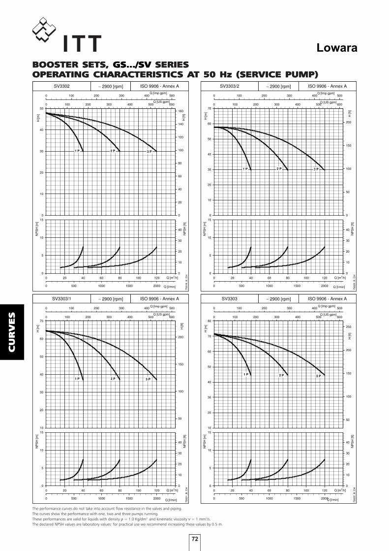
72
Lowara
CU
RV
ES
CU
RV
ES
CU
RV
ES
CU
RV
ES
CU
RV
ES
H [m
]
0
10
20
30
40
50
60
70
Q [US gpm]0 100 200 300 400 500 600
H [f
t]
0
50
100
150
200
Q [Imp gpm]0 100 200 300 400 500
0 20 40 60 80 100 120 140
NP
SH
[m]
0
5
10
15
Q [l/min]0 500 1000 1500 2000
NP
SH
[ft]
0
10
20
30
40
7502
0_B
_CH
SV3303/2 ISO 9906 - Annex A
1 P 2 P 3 P
Q [m3/h]
∼ 2900 [rpm]
H [m
]
10
20
30
40
50
60
70
Q [US gpm]0 100 200 300 400 500 600
H [f
t]
50
100
150
200
Q [Imp gpm]0 100 200 300 400 500
0 20 40 60 80 100 120 140
NP
SH
[m]
0
5
10
15
Q [l/min]0 500 1000 1500 2000
NP
SH
[ft]
0
10
20
30
40
7502
1_B
_CH
SV3303/1 ISO 9906 - Annex A
1 P 2 P 3 P
Q [m3/h]
∼ 2900 [rpm]
H [m
]
10
20
30
40
50
60
70
80
Q [US gpm]0 100 200 300 400 500 600
H [f
t]
50
100
150
200
250
Q [Imp gpm]0 100 200 300 400 500
0 20 40 60 80 100 120 140
NP
SH
[m]
0
5
10
15
Q [l/min]0 500 1000 1500 2000
NP
SH
[ft]
0
10
20
30
40
7502
2_B
_CH
SV3303 ISO 9906 - Annex A
1 P 2 P 3 P
Q [m3/h]
∼ 2900 [rpm]
H [m
]
0
10
20
30
40
50
Q [US gpm]0 100 200 300 400 500 600
H [f
t]
0
20
40
60
80
100
120
140
160
Q [Imp gpm]0 100 200 300 400 500
0 20 40 60 80 100 120 140
NP
SH
[m]
0
5
10
15
Q [l/min]0 500 1000 1500 2000
NP
SH
[ft]
0
10
20
30
40
7501
9_B
_CH
SV3302 ISO 9906 - Annex A
1 P 2 P 3 P
Q [m3/h]
∼ 2900 [rpm]
BOOSTER SETS,BOOSTER SETS,BOOSTER SETS,BOOSTER SETS,BOOSTER SETS, GS.../SV GS.../SV GS.../SV GS.../SV GS.../SV SERIESSERIESSERIESSERIESSERIESOPERAOPERAOPERAOPERAOPERATING CHARACTERISTICTING CHARACTERISTICTING CHARACTERISTICTING CHARACTERISTICTING CHARACTERISTICS AS AS AS AS AT 50 Hz (SERVICE PUMP)T 50 Hz (SERVICE PUMP)T 50 Hz (SERVICE PUMP)T 50 Hz (SERVICE PUMP)T 50 Hz (SERVICE PUMP)
The performance curves do not take into account flow resistance in the valves and piping.The curves show the performance with one, two and three pumps running.These performances are valid for liquids with density ρ = 1.0 Kg/dm3 and kinematic viscosity ν = 1 mm2/s.The declared NPSH values are laboratory values: for practical use we recommend increasing these values by 0.5 m.

73
Lowara
CU
RV
ES
CU
RV
ES
CU
RV
ES
CU
RV
ES
CU
RV
ES
BOOSTER SETS,BOOSTER SETS,BOOSTER SETS,BOOSTER SETS,BOOSTER SETS, GS.../SV GS.../SV GS.../SV GS.../SV GS.../SV SERIESSERIESSERIESSERIESSERIESOPERAOPERAOPERAOPERAOPERATING CHARACTERISTICTING CHARACTERISTICTING CHARACTERISTICTING CHARACTERISTICTING CHARACTERISTICS AS AS AS AS AT 50 Hz (SERVICE PUMP)T 50 Hz (SERVICE PUMP)T 50 Hz (SERVICE PUMP)T 50 Hz (SERVICE PUMP)T 50 Hz (SERVICE PUMP)
The performance curves do not take into account flow resistance in the valves and piping.The curves show the performance with one, two and three pumps running.These performances are valid for liquids with density ρ = 1.0 Kg/dm3 and kinematic viscosity ν = 1 mm2/s.The declared NPSH values are laboratory values: for practical use we recommend increasing these values by 0.5 m.
H [m
]
0
20
40
60
80
100
Q [US gpm]0 100 200 300 400 500 600
H [f
t]
0
50
100
150
200
250
300
Q [Imp gpm]0 100 200 300 400 500
0 20 40 60 80 100 120 140
NP
SH
[m]
0
5
10
15
Q [l/min]0 500 1000 1500 2000
NP
SH
[ft]
0
10
20
30
40
7502
4_B
_CH
SV3304/1 ISO 9906 - Annex A
1 P 2 P 3 P
Q [m3/h]
∼ 2900 [rpm]
H [m
]
0
20
40
60
80
100
Q [US gpm]0 100 200 300 400 500 600
H [f
t]
0
50
100
150
200
250
300
Q [Imp gpm]0 100 200 300 400 500
0 20 40 60 80 100 120 140
NP
SH
[m]
0
5
10
15
Q [l/min]0 500 1000 1500 2000
NP
SH
[ft]
0
10
20
30
40
7502
5_B
_CH
SV3304 ISO 9906 - Annex A
1 P 2 P 3 P
Q [m3/h]
∼ 2900 [rpm]
H [m
]
10
20
30
40
50
60
70
80
90
Q [US gpm]0 100 200 300 400 500 600
H [f
t]
50
100
150
200
250
Q [Imp gpm]0 100 200 300 400 500
0 20 40 60 80 100 120 140
NP
SH
[m]
0
5
10
15
Q [l/min]0 500 1000 1500 2000
NP
SH
[ft]
0
10
20
30
40
7502
3_B
_CH
SV3304/2 ISO 9906 - Annex A
1 P 2 P 3 P
Q [m3/h]
∼ 2900 [rpm]
H [m
]
0
20
40
60
80
100
120
Q [US gpm]0 100 200 300 400 500 600
H [f
t]
0
100
200
300
Q [Imp gpm]0 100 200 300 400 500
0 20 40 60 80 100 120 140
NP
SH
[m]
0
5
10
15
Q [l/min]0 500 1000 1500 2000
NP
SH
[ft]
0
10
20
30
40
7502
6_B
_CH
SV3305/2 ISO 9906 - Annex A
1 P 2 P 3 P
Q [m3/h]
∼ 2900 [rpm]

74
Lowara
CU
RV
ES
CU
RV
ES
CU
RV
ES
CU
RV
ES
CU
RV
ES
BOOSTER SETS,BOOSTER SETS,BOOSTER SETS,BOOSTER SETS,BOOSTER SETS, GS.../SV GS.../SV GS.../SV GS.../SV GS.../SV SERIESSERIESSERIESSERIESSERIESOPERAOPERAOPERAOPERAOPERATING CHARACTERISTICTING CHARACTERISTICTING CHARACTERISTICTING CHARACTERISTICTING CHARACTERISTICS AS AS AS AS AT 50 Hz (SERVICE PUMP)T 50 Hz (SERVICE PUMP)T 50 Hz (SERVICE PUMP)T 50 Hz (SERVICE PUMP)T 50 Hz (SERVICE PUMP)
The performance curves do not take into account flow resistance in the valves and piping.The curves show the performance with one, two and three pumps running.These performances are valid for liquids with density ρ = 1.0 Kg/dm3 and kinematic viscosity ν = 1 mm2/s.The declared NPSH values are laboratory values: for practical use we recommend increasing these values by 0.5 m.
H [m
]
20
40
60
80
100
120
140
Q [US gpm]0 100 200 300 400 500 600
H [f
t]
100
200
300
400
Q [Imp gpm]0 100 200 300 400 500
0 20 40 60 80 100 120 140
NP
SH
[m]
0
5
10
15
Q [l/min]0 500 1000 1500 2000
NP
SH
[ft]
0
10
20
30
40
7502
8_B
_CH
SV3305 ISO 9906 - Annex A
1 P 2 P 3 P
Q [m3/h]
∼ 2900 [rpm]
H [m
]
20
40
60
80
100
120
140
Q [US gpm]0 100 200 300 400 500 600
H [f
t]
100
200
300
400
Q [Imp gpm]0 100 200 300 400 500
0 20 40 60 80 100 120 140
NP
SH
[m]
0
5
10
15
Q [l/min]0 500 1000 1500 2000
NP
SH
[ft]
0
10
20
30
40
7502
9_B
_CH
SV3306/2 ISO 9906 - Annex A
1 P 2 P 3 P
Q [m3/h]
∼ 2900 [rpm]
H [m
]
20
40
60
80
100
120
140
160
Q [US gpm]0 100 200 300 400 500 600
H [f
t]
100
200
300
400
500
Q [Imp gpm]0 100 200 300 400 500
0 20 40 60 80 100 120 140
NP
SH
[m]
0
5
10
15
Q [l/min]0 500 1000 1500 2000
NP
SH
[ft]
0
10
20
30
40
7503
0_B
_CH
SV3306/1 ISO 9906 - Annex A
1 P 2 P 3 P
Q [m3/h]
∼ 2900 [rpm]
H [m
]
20
40
60
80
100
120
Q [US gpm]0 100 200 300 400 500 600
H [f
t]
100
200
300
Q [Imp gpm]0 100 200 300 400 500
0 20 40 60 80 100 120 140
NP
SH
[m]
0
5
10
15
Q [l/min]0 500 1000 1500 2000
NP
SH
[ft]
0
10
20
30
40
7502
7_B
_CH
SV3305/1 ISO 9906 - Annex A
1 P 2 P 3 P
Q [m3/h]
∼ 2900 [rpm]

75
Lowara
CU
RV
ES
CU
RV
ES
CU
RV
ES
CU
RV
ES
CU
RV
ES
H [m
]
20
40
60
80
100
120
140
160
180
Q [US gpm]0 100 200 300 400 500 600
H [f
t]
100
200
300
400
500
Q [Imp gpm]0 100 200 300 400 500
0 20 40 60 80 100 120 140
NP
SH
[m]
0
5
10
15
Q [l/min]0 500 1000 1500 2000
NP
SH
[ft]
0
10
20
30
40
7503
2_B
_CH
SV3307/2 ISO 9906 - Annex A
1 P 2 P 3 P
Q [m3/h]
∼ 2900 [rpm]
H [m
]
0
5
10
15
20
25
Q [US gpm]0 200 400 600 800
H [f
t]
0
20
40
60
80
Q [Imp gpm]0 200 400 600
Q [m3/h]0 50 100 150 200
NP
SH
[m]
0
5
10
15
Q [l/min]0 500 1000 1500 2000 2500 3000
NP
SH
[ft]
0
10
20
30
40
7503
3_B
_CH
SV4601/1 ISO 9906 - Annex A
1 P 2 P 3 P
∼ 2900 [rpm]
H [m
]
0
5
10
15
20
25
30
Q [US gpm]0 200 400 600 800
H [f
t]
0
20
40
60
80
Q [Imp gpm]0 200 400 600
Q [m3/h]0 50 100 150 200
NP
SH
[m]
0
5
10
15
Q [l/min]0 500 1000 1500 2000 2500 3000
NP
SH
[ft]
0
10
20
30
40
7503
4_B
_CH
SV4601 ISO 9906 - Annex A
1 P 2 P 3 P
∼ 2900 [rpm]
H [m
]
20
40
60
80
100
120
140
160
Q [US gpm]0 100 200 300 400 500 600
H [f
t]
100
200
300
400
500
Q [Imp gpm]0 100 200 300 400 500
0 20 40 60 80 100 120 140
NP
SH
[m]
0
5
10
15
Q [l/min]0 500 1000 1500 2000
NP
SH
[ft]
0
10
20
30
40
7503
1_B
_CH
SV3306 ISO 9906 - Annex A
1 P 2 P 3 P
Q [m3/h]
∼ 2900 [rpm]
BOOSTER SETS,BOOSTER SETS,BOOSTER SETS,BOOSTER SETS,BOOSTER SETS, GS.../SV GS.../SV GS.../SV GS.../SV GS.../SV SERIESSERIESSERIESSERIESSERIESOPERAOPERAOPERAOPERAOPERATING CHARACTERISTICTING CHARACTERISTICTING CHARACTERISTICTING CHARACTERISTICTING CHARACTERISTICS AS AS AS AS AT 50 Hz (SERVICE PUMP)T 50 Hz (SERVICE PUMP)T 50 Hz (SERVICE PUMP)T 50 Hz (SERVICE PUMP)T 50 Hz (SERVICE PUMP)
The performance curves do not take into account flow resistance in the valves and piping.The curves show the performance with one, two and three pumps running.These performances are valid for liquids with density ρ = 1.0 Kg/dm3 and kinematic viscosity ν = 1 mm2/s.The declared NPSH values are laboratory values: for practical use we recommend increasing these values by 0.5 m.

76
Lowara
CU
RV
ES
CU
RV
ES
CU
RV
ES
CU
RV
ES
CU
RV
ES
H [m
]
0
10
20
30
40
50
60Q [US gpm]0 200 400 600 800
H [f
t]
0
50
100
150
Q [Imp gpm]0 200 400 600
Q [m3/h]0 50 100 150 200
NP
SH
[m]
0
5
10
15
Q [l/min]0 500 1000 1500 2000 2500 3000
NP
SH
[ft]
0
10
20
30
40
7503
6_B
_CH
SV4602 ISO 9906 - Annex A
1 P 2 P 3 P
∼ 2900 [rpm]
H [m
]
0
10
20
30
40
50
60
70Q [US gpm]0 200 400 600 800
H [f
t]
0
50
100
150
200
Q [Imp gpm]0 200 400 600
Q [m3/h]0 50 100 150 200
NP
SH
[m]
0
5
10
15
Q [l/min]0 500 1000 1500 2000 2500 3000
NP
SH
[ft]
0
10
20
30
40
7503
7_B
_CH
SV4603/2 ISO 9906 - Annex A
1 P 2 P 3 P
∼ 2900 [rpm]
H [m
]
0
20
40
60
80
100
Q [US gpm]0 200 400 600 800
H [f
t]
0
50
100
150
200
250
300
Q [Imp gpm]0 200 400 600
Q [m3/h]0 50 100 150 200
NP
SH
[m]
0
5
10
15
Q [l/min]0 500 1000 1500 2000 2500 3000
NP
SH
[ft]
0
10
20
30
40
7503
8_B
_CH
SV4603 ISO 9906 - Annex A
1 P 2 P 3 P
∼ 2900 [rpm]
H [m
]
0
10
20
30
40
50
Q [US gpm]0 200 400 600 800
H [f
t]
0
50
100
150
Q [Imp gpm]0 200 400 600
Q [m3/h]0 50 100 150 200
NP
SH
[m]
0
5
10
15
Q [l/min]0 500 1000 1500 2000 2500 3000
NP
SH
[ft]
0
10
20
30
40
7503
5_B
_CH
SV4602/2 ISO 9906 - Annex A
1 P 2 P 3 P
∼ 2900 [rpm]
BOOSTER SETS,BOOSTER SETS,BOOSTER SETS,BOOSTER SETS,BOOSTER SETS, GS.../SV GS.../SV GS.../SV GS.../SV GS.../SV SERIESSERIESSERIESSERIESSERIESOPERAOPERAOPERAOPERAOPERATING CHARACTERISTICTING CHARACTERISTICTING CHARACTERISTICTING CHARACTERISTICTING CHARACTERISTICS AS AS AS AS AT 50 Hz (SERVICE PUMP)T 50 Hz (SERVICE PUMP)T 50 Hz (SERVICE PUMP)T 50 Hz (SERVICE PUMP)T 50 Hz (SERVICE PUMP)
The performance curves do not take into account flow resistance in the valves and piping.The curves show the performance with one, two and three pumps running.These performances are valid for liquids with density ρ = 1.0 Kg/dm3 and kinematic viscosity ν = 1 mm2/s.The declared NPSH values are laboratory values: for practical use we recommend increasing these values by 0.5 m.

77
Lowara
CU
RV
ES
CU
RV
ES
CU
RV
ES
CU
RV
ES
CU
RV
ES
H [m
]
0
20
40
60
80
100
120
Q [US gpm]0 200 400 600 800
H [f
t]
0
100
200
300
Q [Imp gpm]0 200 400 600
Q [m3/h]0 50 100 150 200
NP
SH
[m]
0
5
10
15
Q [l/min]0 500 1000 1500 2000 2500 3000
NP
SH
[ft]
0
10
20
30
40
7504
0_B
_CH
SV4604 ISO 9906 - Annex A
1 P 2 P 3 P
∼ 2900 [rpm]
H [m
]
0
20
40
60
80
100
120
140Q [US gpm]0 200 400 600 800
H [f
t]
0
100
200
300
400
Q [Imp gpm]0 200 400 600
Q [m3/h]0 50 100 150 200
NP
SH
[m]
0
5
10
15
Q [l/min]0 500 1000 1500 2000 2500 3000
NP
SH
[ft]
0
10
20
30
40
7504
1_B
_CH
SV4605/2 ISO 9906 - Annex A
1 P 2 P 3 P
∼ 2900 [rpm]
H [m
]
0
20
40
60
80
100
120
140
160Q [US gpm]0 200 400 600 800
H [f
t]
0
100
200
300
400
500
Q [Imp gpm]0 200 400 600
Q [m3/h]0 50 100 150 200
NP
SH
[m]
0
5
10
15
Q [l/min]0 500 1000 1500 2000 2500 3000
NP
SH
[ft]
0
10
20
30
40
7504
2_B
_CH
SV4605 ISO 9906 - Annex A
1 P 2 P 3 P
∼ 2900 [rpm]
H [m
]
0
20
40
60
80
100Q [US gpm]0 200 400 600 800
H [f
t]
0
50
100
150
200
250
300
Q [Imp gpm]0 200 400 600
Q [m3/h]0 50 100 150 200
NP
SH
[m]
0
5
10
15
Q [l/min]0 500 1000 1500 2000 2500 3000
NP
SH
[ft]
0
10
20
30
40
7503
9_B
_CH
SV4604/2 ISO 9906 - Annex A
1 P 2 P 3 P
∼ 2900 [rpm]
BOOSTER SETS,BOOSTER SETS,BOOSTER SETS,BOOSTER SETS,BOOSTER SETS, GS.../SV GS.../SV GS.../SV GS.../SV GS.../SV SERIESSERIESSERIESSERIESSERIESOPERAOPERAOPERAOPERAOPERATING CHARACTERISTICTING CHARACTERISTICTING CHARACTERISTICTING CHARACTERISTICTING CHARACTERISTICS AS AS AS AS AT 50 Hz (SERVICE PUMP)T 50 Hz (SERVICE PUMP)T 50 Hz (SERVICE PUMP)T 50 Hz (SERVICE PUMP)T 50 Hz (SERVICE PUMP)
The performance curves do not take into account flow resistance in the valves and piping.The curves show the performance with one, two and three pumps running.These performances are valid for liquids with density ρ = 1.0 Kg/dm3 and kinematic viscosity ν = 1 mm2/s.The declared NPSH values are laboratory values: for practical use we recommend increasing these values by 0.5 m.
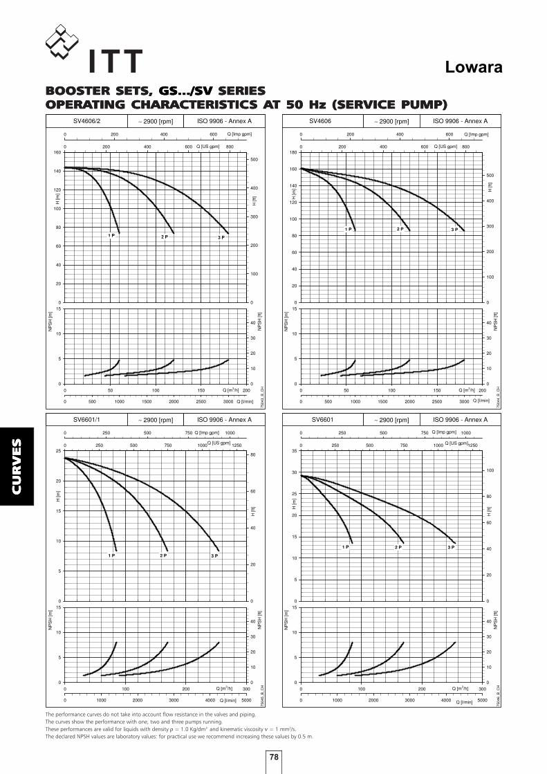
78
Lowara
CU
RV
ES
CU
RV
ES
CU
RV
ES
CU
RV
ES
CU
RV
ES
H [m
]
0
20
40
60
80
100
120
140
160
180Q [US gpm]0 200 400 600 800
H [f
t]
0
100
200
300
400
500
Q [Imp gpm]0 200 400 600
Q [m3/h]0 50 100 150 200
NP
SH
[m]
0
5
10
15
Q [l/min]0 500 1000 1500 2000 2500 3000
NP
SH
[ft]
0
10
20
30
40
7504
4_B
_CH
SV4606 ISO 9906 - Annex A
1 P 2 P 3 P
∼ 2900 [rpm]
H [m
]
0
5
10
15
20
25
Q [US gpm]0 250 500 750 1000 1250
H [f
t]
0
20
40
60
80
Q [Imp gpm]0 250 500 750 1000
Q [m3/h]0 100 200 300
NP
SH
[m]
0
5
10
15
Q [l/min]0 1000 2000 3000 4000 5000
NP
SH
[ft]
0
10
20
30
40
7504
5_B
_CH
SV6601/1 ISO 9906 - Annex A
1 P 2 P 3 P
∼ 2900 [rpm]
H [m
]
0
5
10
15
20
25
30
35
Q [US gpm]0 250 500 750 1000 1250
H [f
t]
0
20
40
60
80
100
Q [Imp gpm]0 250 500 750 1000
Q [m3/h]0 100 200 300
NP
SH
[m]
0
5
10
15
Q [l/min]0 1000 2000 3000 4000 5000
NP
SH
[ft]
0
10
20
30
40
7504
6_B
_CH
SV6601 ISO 9906 - Annex A
1 P 2 P 3 P
∼ 2900 [rpm]
H [m
]
0
20
40
60
80
100
120
140
160Q [US gpm]0 200 400 600 800
H [f
t]
0
100
200
300
400
500
Q [Imp gpm]0 200 400 600
Q [m3/h]0 50 100 150 200
NP
SH
[m]
0
5
10
15
Q [l/min]0 500 1000 1500 2000 2500 3000
NP
SH
[ft]
0
10
20
30
40
7504
3_B
_CH
SV4606/2 ISO 9906 - Annex A
1 P 2 P 3 P
∼ 2900 [rpm]
BOOSTER SETS,BOOSTER SETS,BOOSTER SETS,BOOSTER SETS,BOOSTER SETS, GS.../SV GS.../SV GS.../SV GS.../SV GS.../SV SERIESSERIESSERIESSERIESSERIESOPERAOPERAOPERAOPERAOPERATING CHARACTERISTICTING CHARACTERISTICTING CHARACTERISTICTING CHARACTERISTICTING CHARACTERISTICS AS AS AS AS AT 50 Hz (SERVICE PUMP)T 50 Hz (SERVICE PUMP)T 50 Hz (SERVICE PUMP)T 50 Hz (SERVICE PUMP)T 50 Hz (SERVICE PUMP)
The performance curves do not take into account flow resistance in the valves and piping.The curves show the performance with one, two and three pumps running.These performances are valid for liquids with density ρ = 1.0 Kg/dm3 and kinematic viscosity ν = 1 mm2/s.The declared NPSH values are laboratory values: for practical use we recommend increasing these values by 0.5 m.
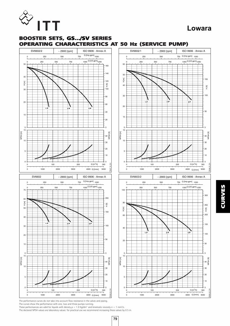
79
Lowara
CU
RV
ES
CU
RV
ES
CU
RV
ES
CU
RV
ES
CU
RV
ES
H [m
]
0
10
20
30
40
50
60
Q [US gpm]0 250 500 750 1000 1250
H [f
t]
0
50
100
150
Q [Imp gpm]0 250 500 750 1000
Q [m3/h]0 100 200 300
NP
SH
[m]
0
5
10
15
Q [l/min]0 1000 2000 3000 4000 5000
NP
SH
[ft]
0
10
20
30
40
7504
8_B
_CH
SV6602/1 ISO 9906 - Annex A
1 P 2 P 3 P
∼ 2900 [rpm]
H [m
]
0
10
20
30
40
50
60
70
Q [US gpm]0 250 500 750 1000 1250
H [f
t]
0
50
100
150
200
Q [Imp gpm]0 250 500 750 1000
Q [m3/h]0 100 200 300
NP
SH
[m]
0
5
10
15
Q [l/min]0 1000 2000 3000 4000 5000
NP
SH
[ft]
0
10
20
30
40
7504
9_B
_CH
SV6602 ISO 9906 - Annex A
1 P 2 P 3 P
∼ 2900 [rpm]
H [m
]
0
20
40
60
80
100
Q [US gpm]0 250 500 750 1000 1250
H [f
t]
0
50
100
150
200
250
300
Q [Imp gpm]0 250 500 750 1000
Q [m3/h]0 100 200 300
NP
SH
[m]
0
5
10
15
Q [l/min]0 1000 2000 3000 4000 5000
NP
SH
[ft]
0
10
20
30
40
7505
0_B
_CH
SV6603/2 ISO 9906 - Annex A
1 P 2 P 3 P
∼ 2900 [rpm]
H [m
]
0
10
20
30
40
50
Q [US gpm]0 250 500 750 1000 1250
H [f
t]
0
20
40
60
80
100
120
140
160
Q [Imp gpm]0 250 500 750 1000
Q [m3/h]0 100 200 300
NP
SH
[m]
0
5
10
15
Q [l/min]0 1000 2000 3000 4000 5000
NP
SH
[ft]
0
10
20
30
40
7504
7_B
_CH
SV6602/2 ISO 9906 - Annex A
1 P 2 P 3 P
∼ 2900 [rpm]
BOOSTER SETS,BOOSTER SETS,BOOSTER SETS,BOOSTER SETS,BOOSTER SETS, GS.../SV GS.../SV GS.../SV GS.../SV GS.../SV SERIESSERIESSERIESSERIESSERIESOPERAOPERAOPERAOPERAOPERATING CHARACTERISTICTING CHARACTERISTICTING CHARACTERISTICTING CHARACTERISTICTING CHARACTERISTICS AS AS AS AS AT 50 Hz (SERVICE PUMP)T 50 Hz (SERVICE PUMP)T 50 Hz (SERVICE PUMP)T 50 Hz (SERVICE PUMP)T 50 Hz (SERVICE PUMP)
The performance curves do not take into account flow resistance in the valves and piping.The curves show the performance with one, two and three pumps running.These performances are valid for liquids with density ρ = 1.0 Kg/dm3 and kinematic viscosity ν = 1 mm2/s.The declared NPSH values are laboratory values: for practical use we recommend increasing these values by 0.5 m.

80
Lowara
CU
RV
ES
CU
RV
ES
CU
RV
ES
CU
RV
ES
CU
RV
ES
H [m
]
0
20
40
60
80
100
Q [US gpm]0 250 500 750 1000 1250
H [f
t]
0
50
100
150
200
250
300
Q [Imp gpm]0 250 500 750 1000
Q [m3/h]0 100 200 300
NP
SH
[m]
0
5
10
15
Q [l/min]0 1000 2000 3000 4000 5000
NP
SH
[ft]
0
10
20
30
40
7505
2_B
_CH
SV6603 ISO 9906 - Annex A
1 P 2 P 3 P
∼ 2900 [rpm]
H [m
]
0
20
40
60
80
100
120
Q [US gpm]0 250 500 750 1000 1250
H [f
t]
0
100
200
300
Q [Imp gpm]0 250 500 750 1000
Q [m3/h]0 100 200 300
NP
SH
[m]
0
5
10
15
Q [l/min]0 1000 2000 3000 4000 5000
NP
SH
[ft]
0
10
20
30
40
7505
3_B
_CH
SV6604/2 ISO 9906 - Annex A
1 P 2 P 3 P
∼ 2900 [rpm]
H [m
]
0
20
40
60
80
100
120
Q [US gpm]0 250 500 750 1000 1250
H [f
t]
0
100
200
300
Q [Imp gpm]0 250 500 750 1000
Q [m3/h]0 100 200 300
NP
SH
[m]
0
5
10
15
Q [l/min]0 1000 2000 3000 4000 5000
NP
SH
[ft]
0
10
20
30
40
7505
4_B
_CH
SV6604/1 ISO 9906 - Annex A
1 P 2 P 3 P
∼ 2900 [rpm]
H [m
]
0
20
40
60
80
100
Q [US gpm]0 250 500 750 1000 1250
H [f
t]
0
50
100
150
200
250
300
Q [Imp gpm]0 250 500 750 1000
Q [m3/h]0 100 200 300
NP
SH
[m]
0
5
10
15
Q [l/min]0 1000 2000 3000 4000 5000
NP
SH
[ft]
0
10
20
30
40
7505
1_B
_CH
SV6603/1 ISO 9906 - Annex A
1 P 2 P 3 P
∼ 2900 [rpm]
BOOSTER SETS,BOOSTER SETS,BOOSTER SETS,BOOSTER SETS,BOOSTER SETS, GS.../SV GS.../SV GS.../SV GS.../SV GS.../SV SERIESSERIESSERIESSERIESSERIESOPERAOPERAOPERAOPERAOPERATING CHARACTERISTICTING CHARACTERISTICTING CHARACTERISTICTING CHARACTERISTICTING CHARACTERISTICS AS AS AS AS AT 50 Hz (SERVICE PUMP)T 50 Hz (SERVICE PUMP)T 50 Hz (SERVICE PUMP)T 50 Hz (SERVICE PUMP)T 50 Hz (SERVICE PUMP)
The performance curves do not take into account flow resistance in the valves and piping.The curves show the performance with one, two and three pumps running.These performances are valid for liquids with density ρ = 1.0 Kg/dm3 and kinematic viscosity ν = 1 mm2/s.The declared NPSH values are laboratory values: for practical use we recommend increasing these values by 0.5 m.

81
Lowara
CU
RV
ES
CU
RV
ES
CU
RV
ES
CU
RV
ES
CU
RV
ES
H [m
]
0
20
40
60
80
100
120
140
160
Q [US gpm]0 250 500 750 1000 1250
H [f
t]
0
100
200
300
400
500
Q [Imp gpm]0 250 500 750 1000
Q [m3/h]0 100 200 300
NP
SH
[m]
0
5
10
15
Q [l/min]0 1000 2000 3000 4000 5000
NP
SH
[ft]
0
10
20
30
40
7673
9_A
_CH
SV6605/2 ISO 9906 - Annex A
1 P 2 P 3 P
∼ 2900 [rpm]
H [m
]
0
20
40
60
80
100
120
140
160
Q [US gpm]0 250 500 750 1000 1250
H [f
t]
0
100
200
300
400
500
Q [Imp gpm]0 250 500 750 1000
Q [m3/h]0 100 200 300
NP
SH
[m]
0
5
10
15
Q [l/min]0 1000 2000 3000 4000 5000
NP
SH
[ft]
0
10
20
30
40
7674
0_A
_CH
SV6605/1 ISO 9906 - Annex A
1 P 2 P 3 P
∼ 2900 [rpm]
H [m
]
0
20
40
60
80
100
120
140
160
Q [US gpm]0 250 500 750 1000 1250
H [f
t]
0
100
200
300
400
500
Q [Imp gpm]0 250 500 750 1000
Q [m3/h]0 100 200 300
NP
SH
[m]
0
5
10
15
Q [l/min]0 1000 2000 3000 4000 5000
NP
SH
[ft]
0
10
20
30
40
7674
1_A
_CH
SV6605 ISO 9906 - Annex A
1 P 2 P 3 P
∼ 2900 [rpm]
H [m
]
0
20
40
60
80
100
120
140
Q [US gpm]0 250 500 750 1000 1250
H [f
t]
0
100
200
300
400
Q [Imp gpm]0 250 500 750 1000
Q [m3/h]0 100 200 300
NP
SH
[m]
0
5
10
15
Q [l/min]0 1000 2000 3000 4000 5000
NP
SH
[ft]
0
10
20
30
40
7505
5_B
_CH
SV6604 ISO 9906 - Annex A
1 P 2 P 3 P
∼ 2900 [rpm]
BOOSTER SETS,BOOSTER SETS,BOOSTER SETS,BOOSTER SETS,BOOSTER SETS, GS.../SV GS.../SV GS.../SV GS.../SV GS.../SV SERIESSERIESSERIESSERIESSERIESOPERAOPERAOPERAOPERAOPERATING CHARACTERISTICTING CHARACTERISTICTING CHARACTERISTICTING CHARACTERISTICTING CHARACTERISTICS AS AS AS AS AT 50 Hz (SERVICE PUMP)T 50 Hz (SERVICE PUMP)T 50 Hz (SERVICE PUMP)T 50 Hz (SERVICE PUMP)T 50 Hz (SERVICE PUMP)
The performance curves do not take into account flow resistance in the valves and piping.The curves show the performance with one, two and three pumps running.These performances are valid for liquids with density ρ = 1.0 Kg/dm3 and kinematic viscosity ν = 1 mm2/s.The declared NPSH values are laboratory values: for practical use we recommend increasing these values by 0.5 m.

82
Lowara
CU
RV
ES
CU
RV
ES
CU
RV
ES
CU
RV
ES
CU
RV
ES
H [m
]
0
10
20
30
Q [US gpm]0 500 1000 1500
H [f
t]
0
20
40
60
80
100
Q [Imp gpm]0 500 1000
Q [m3/h]0 100 200 300 400
NP
SH
[m]
0
5
10
15
Q [l/min]0 2000 4000 6000
NP
SH
[ft]
0
10
20
30
40
7505
7_B
_CH
SV9201 ISO 9906 - Annex A
1 P 2 P 3 P
∼ 2900 [rpm]
H [m
]
0
10
20
30
40
50
60Q [US gpm]0 500 1000 1500
H [f
t]
0
50
100
150
Q [Imp gpm]0 500 1000
Q [m3/h]0 100 200 300 400
NP
SH
[m]
0
5
10
15
Q [l/min]0 2000 4000 6000
NP
SH
[ft]
0
10
20
30
40
7505
8_B
_CH
SV9202/2 ISO 9906 - Annex A
1 P 2 P 3 P
∼ 2900 [rpm]
H [m
]
0
20
40
60
80
Q [US gpm]0 500 1000 1500
H [f
t]
0
50
100
150
200
250
Q [Imp gpm]0 500 1000
Q [m3/h]0 100 200 300 400
NP
SH
[m]
0
5
10
15
Q [l/min]0 2000 4000 6000
NP
SH
[ft]
0
10
20
30
40
7505
9_B
_CH
SV9202 ISO 9906 - Annex A
1 P 2 P 3 P
∼ 2900 [rpm]
H [m
]
0
5
10
15
20
25
30Q [US gpm]0 500 1000 1500
H [f
t]
0
20
40
60
80
Q [Imp gpm]0 500 1000
Q [m3/h]0 100 200 300 400
NP
SH
[m]
0
5
10
15
Q [l/min]0 2000 4000 6000
NP
SH
[ft]
0
10
20
30
40
7505
6_B
_CH
SV9201/1 ISO 9906 - Annex A
1 P 2 P 3 P
∼ 2900 [rpm]
BOOSTER SETS,BOOSTER SETS,BOOSTER SETS,BOOSTER SETS,BOOSTER SETS, GS.../SV GS.../SV GS.../SV GS.../SV GS.../SV SERIESSERIESSERIESSERIESSERIESOPERAOPERAOPERAOPERAOPERATING CHARACTERISTICTING CHARACTERISTICTING CHARACTERISTICTING CHARACTERISTICTING CHARACTERISTICS AS AS AS AS AT 50 Hz (SERVICE PUMP)T 50 Hz (SERVICE PUMP)T 50 Hz (SERVICE PUMP)T 50 Hz (SERVICE PUMP)T 50 Hz (SERVICE PUMP)
The performance curves do not take into account flow resistance in the valves and piping.The curves show the performance with one, two and three pumps running.These performances are valid for liquids with density ρ = 1.0 Kg/dm3 and kinematic viscosity ν = 1 mm2/s.The declared NPSH values are laboratory values: for practical use we recommend increasing these values by 0.5 m.

83
Lowara
CU
RV
ES
CU
RV
ES
CU
RV
ES
CU
RV
ES
CU
RV
ES
H [m
]
0
20
40
60
80
100
120
Q [US gpm]0 500 1000 1500
H [f
t]
0
100
200
300
Q [Imp gpm]0 500 1000
Q [m3/h]0 100 200 300 400
NP
SH
[m]
0
5
10
15
Q [l/min]0 2000 4000 6000
NP
SH
[ft]
0
10
20
30
40
7506
1_B
_CH
SV9203 ISO 9906 - Annex A
1 P 2 P 3 P
∼ 2900 [rpm]
H [m
]
0
20
40
60
80
100
120
140
Q [US gpm]0 500 1000 1500
H [f
t]
0
100
200
300
400
Q [Imp gpm]0 500 1000
Q [m3/h]0 100 200 300 400
NP
SH
[m]
0
5
10
15
Q [l/min]0 2000 4000 6000
NP
SH
[ft]
0
10
20
30
40
7674
2_A
_CH
SV9204/2 ISO 9906 - Annex A
1 P 2 P 3 P
∼ 2900 [rpm]
H [m
]
0
20
40
60
80
100
120
140
Q [US gpm]0 500 1000 1500
H [f
t]
0
100
200
300
400
Q [Imp gpm]0 500 1000
Q [m3/h]0 100 200 300 400
NP
SH
[m]
0
5
10
15
Q [l/min]0 2000 4000 6000
NP
SH
[ft]
0
10
20
30
40
7674
3_A
_CH
SV9204 ISO 9906 - Annex A
1 P 2 P 3 P
∼ 2900 [rpm]
H [m
]
0
20
40
60
80
100
Q [US gpm]0 500 1000 1500
H [f
t]
0
50
100
150
200
250
300
Q [Imp gpm]0 500 1000
Q [m3/h]0 100 200 300 400
NP
SH
[m]
0
5
10
15
Q [l/min]0 2000 4000 6000
NP
SH
[ft]
0
10
20
30
40
7506
0_B
_CH
SV9203/2 ISO 9906 - Annex A
1 P 2 P 3 P
∼ 2900 [rpm]
BOOSTER SETS,BOOSTER SETS,BOOSTER SETS,BOOSTER SETS,BOOSTER SETS, GS.../SV GS.../SV GS.../SV GS.../SV GS.../SV SERIESSERIESSERIESSERIESSERIESOPERAOPERAOPERAOPERAOPERATING CHARACTERISTICTING CHARACTERISTICTING CHARACTERISTICTING CHARACTERISTICTING CHARACTERISTICS AS AS AS AS AT 50 Hz (SERVICE PUMP)T 50 Hz (SERVICE PUMP)T 50 Hz (SERVICE PUMP)T 50 Hz (SERVICE PUMP)T 50 Hz (SERVICE PUMP)
The performance curves do not take into account flow resistance in the valves and piping.The curves show the performance with one, two and three pumps running.These performances are valid for liquids with density ρ = 1.0 Kg/dm3 and kinematic viscosity ν = 1 mm2/s.The declared NPSH values are laboratory values: for practical use we recommend increasing these values by 0.5 m.

84
Lowara
CU
RV
ES
CU
RV
ES
CU
RV
ES
CU
RV
ES
CU
RV
ES
H [m
]
0
20
40
60
80
100
120
140
160
Q [US gpm]0 500 1000 1500
H [f
t]
0
100
200
300
400
500
Q [Imp gpm]0 500 1000
Q [m3/h]0 100 200 300 400
NP
SH
[m]
0
5
10
15
Q [l/min]0 2000 4000 6000
NP
SH
[ft]
0
10
20
30
40
7674
4_A
_CH
SV9205/2 ISO 9906 - Annex A
1 P 2 P 3 P
∼ 2900 [rpm]
BOOSTER SETS,BOOSTER SETS,BOOSTER SETS,BOOSTER SETS,BOOSTER SETS, GS.../SV GS.../SV GS.../SV GS.../SV GS.../SV SERIESSERIESSERIESSERIESSERIESOPERAOPERAOPERAOPERAOPERATING CHARACTERISTICTING CHARACTERISTICTING CHARACTERISTICTING CHARACTERISTICTING CHARACTERISTICS AS AS AS AS AT 50 Hz (SERVICE PUMP)T 50 Hz (SERVICE PUMP)T 50 Hz (SERVICE PUMP)T 50 Hz (SERVICE PUMP)T 50 Hz (SERVICE PUMP)
The performance curves do not take into account flow resistance in the valves and piping.The curves show the performance with one, two and three pumps running.These performances are valid for liquids with density ρ = 1.0 Kg/dm3 and kinematic viscosity ν = 1 mm2/s.The declared NPSH values are laboratory values: for practical use we recommend increasing these values by 0.5 m.

85
Lowara
CU
RV
ES
CU
RV
ES
CU
RV
ES
CU
RV
ES
CU
RV
ES
Hc
[m]
0,000
0,002
0,004
0,006
0,008
0,0100 10 20 30 40 50 60 70
Hc
[ft]
0,00
0,01
0,02
0,03
0 10 20 30 40 50
Col 1 vs Col 2 Col 50 vs Col 51 Col 50 vs Col 51
0 2 4 6 8 10 12 14 16
Hc
[m]
0,0
0,5
1,0
1,5
2,0
2,5
0 50 100 150 200 250
Hc
[ft]
0
1
2
3
4
5
6
7
8
7680
5_A
_CH
10SV
Q [m3/h]
Q [l/min]
Q [US gpm]
Q [Imp gpm]
A
B
Hc
[m]
0,0
0,5
1,0
1,5
2,0
2,50 10 20 30 40 50 60 70
Hc
[ft]
0
1
2
3
4
5
6
7
8
0 10 20 30 40 50
Col 1 vs Col 2 Col 50 vs Col 51 Col 50 vs Col 51
0 2 4 6 8 10 12 14 16
Hc
[m]
0,000
0,002
0,004
0,006
0,008
0,010
0 50 100 150 200 250
Hc
[ft]
0,00
0,01
0,02
0,03
7680
8_A
_CH
10SV
Q [m3/h]
Q [l/min]
Q [US gpm]
Q [Imp gpm]
A
B
Hc
[m]
0
1
2
3
4
50 20 40 60 80 100 120
Hc
[ft]
0
5
10
15
0 20 40 60 80 100
Col 1 vs Col 2 Col 50 vs Col 51 Col 50 vs Col 51
0 5 10 15 20 25 30
Hc
[m]
0,000
0,002
0,004
0,006
0,008
0,010
0 100 200 300 400 500
Hc
[ft]
0,00
0,01
0,02
0,03
7680
9_A
_CH
15SV
Q [m3/h]
Q [l/min]
Q [US gpm]
Q [Imp gpm]
A
B
Hc
[m]
0,000
0,002
0,004
0,006
0,008
0,0100 20 40 60 80 100 120
Hc
[ft]
0,00
0,01
0,02
0,03
0 20 40 60 80 100
Col 1 vs Col 2 Col 50 vs Col 51 Col 50 vs Col 51
0 5 10 15 20 25 30
Hc
[m]
0
1
2
3
4
5
0 100 200 300 400 500
Hc
[ft]
0
5
10
15
7680
6_A
_CH
15SV
Q [m3/h]
Q [l/min]
Q [US gpm]
Q [Imp gpm]
A
B
BOOSTER SETS,BOOSTER SETS,BOOSTER SETS,BOOSTER SETS,BOOSTER SETS, GS.../SV GS.../SV GS.../SV GS.../SV GS.../SV SERIESSERIESSERIESSERIESSERIESHc PRESHc PRESHc PRESHc PRESHc PRESSURE DROP CURVESURE DROP CURVESURE DROP CURVESURE DROP CURVESURE DROP CURVE
The declared curves are valid for liquids with density ρ = 1.0 Kg/dm3 and kinematic viscosity ν = 1 mm2/sec.Hc (A): Pressure drop curve with check valve installed on the delivery side of the pump.Hc (B): Pressure drop curve with check valve installed on the suction side of the pump.The pressure drops do not consider the pressure drops distributed in the manifold.
SUCTION SIDE DISCHARGE SIDE
SUCTION SIDE DISCHARGE SIDE

86
Lowara
CU
RV
ES
CU
RV
ES
CU
RV
ES
CU
RV
ES
CU
RV
ES
Hc
[m]
0
2
4
6
80 20 40 60 80 100 120 140
Hc
[ft]
0
5
10
15
20
25
0 20 40 60 80 100 120
Col 1 vs Col 2 Col 50 vs Col 51 Col 50 vs Col 51
0 5 10 15 20 25 30 35
Hc
[m]
0,000
0,002
0,004
0,006
0,008
0,010
0 100 200 300 400 500
Hc
[ft]
0,00
0,01
0,02
0,03
7681
0_A
_CH
22SV
Q [m3/h]
Q [l/min]
Q [US gpm]
Q [Imp gpm]
A
B
Hc
[m]
0,000
0,002
0,004
0,006
0,008
0,010
0,012
0,014
0 20 40 60 80 100 120 140
Hc
[ft]
0,00
0,01
0,02
0,03
0,04
0 20 40 60 80 100 120
Col 1 vs Col 2 Col 50 vs Col 51 Col 50 vs Col 51
0 5 10 15 20 25 30 35
Hc
[m]
0
2
4
6
8
10
0 100 200 300 400 500
Hc
[ft]
0
5
10
15
20
25
30
7680
7_A
_CH
22SV
Q [m3/h]
Q [l/min]
Q [US gpm]
Q [Imp gpm]
A
B
Hc
[m]
0
1
2
3
4
50 20 40 60 80 100 120 140 160 180 200 220
Hc
[ft]
0
5
10
15
0 20 40 60 80 100 120 140 160 180
Col 1 vs Col 2 Col 50 vs Col 51 Col 50 vs Col 51
0 10 20 30 40 50
Hc
[m]
0,0
0,2
0,4
0,6
0,8
0 200 400 600 800
Hc
[ft]
0,0
0,5
1,0
1,5
2,0
2,5
7672
7_A
_CH
SV33
Q [m3/h]
Q [l/min]
Q [US gpm]
Q [Imp gpm]
A
B
Hc
[m]
0,0
0,2
0,4
0,6
0,80 20 40 60 80 100 120 140 160 180 200 220
Hc
[ft]
0,0
0,5
1,0
1,5
2,0
2,5
0 20 40 60 80 100 120 140 160 180
Col 1 vs Col 2 Col 50 vs Col 51 Col 50 vs Col 51
0 10 20 30 40 50
Hc
[m]
0
1
2
3
4
5
0 200 400 600 800
Hc
[ft]
0
5
10
15
7673
5_A
_CH
SV33
Q [m3/h]
Q [l/min]
Q [US gpm]
Q [Imp gpm]
A
B
BOOSTER SETS,BOOSTER SETS,BOOSTER SETS,BOOSTER SETS,BOOSTER SETS, GS.../SV GS.../SV GS.../SV GS.../SV GS.../SV SERIESSERIESSERIESSERIESSERIESHc PRESHc PRESHc PRESHc PRESHc PRESSURE DROP CURVESURE DROP CURVESURE DROP CURVESURE DROP CURVESURE DROP CURVE
The declared curves are valid for liquids with density ρ = 1.0 Kg/dm3 and kinematic viscosity ν = 1 mm2/sec.Hc (A): Pressure drop curve with check valve installed on the delivery side of the pump.Hc (B): Pressure drop curve with check valve installed on the suction side of the pump.The pressure drops do not consider the pressure drops distributed in the manifold.
SUCTION SIDE DISCHARGE SIDE
SUCTION SIDE DISCHARGE SIDE

87
Lowara
CU
RV
ES
CU
RV
ES
CU
RV
ES
CU
RV
ES
CU
RV
ES
Hc
[m]
0
1
2
3
4
50 50 100 150 200 250 300
Hc
[ft]
0
5
10
15
0 50 100 150 200 250
Col 1 vs Col 2 Col 50 vs Col 51 Col 50 vs Col 51
0 10 20 30 40 50 60 70
Hc
[m]
0,0
0,2
0,4
0,6
0,8
0 200 400 600 800 1000
Hc
[ft]
0,0
0,5
1,0
1,5
2,0
2,5
7672
8_A
_CH
SV46
Q [m3/h]
Q [l/min]
Q [US gpm]
Q [Imp gpm]
A
B
Hc
[m]
0,0
0,2
0,4
0,6
0,80 50 100 150 200 250 300
Hc
[ft]
0,0
0,5
1,0
1,5
2,0
2,5
0 50 100 150 200 250
Col 1 vs Col 2 Col 50 vs Col 51 Col 50 vs Col 51
0 10 20 30 40 50 60 70
Hc
[m]
0
1
2
3
4
5
0 200 400 600 800 1000
Hc
[ft]
0
5
10
15
7673
6_A
_CH
SV46
Q [m3/h]
Q [l/min]
Q [US gpm]
Q [Imp gpm]
A
B
Hc
[m]
0
1
2
30 100 200 300 400
Hc
[ft]
0,0
2,5
5,0
7,5
0 50 100 150 200 250 300 350
Col 1 vs Col 2 Col 50 vs Col 51 Col 50 vs Col 51
0 20 40 60 80 100
Hc
[m]
0,0
0,2
0,4
0,6
0 200 400 600 800 1000 1200 1400 1600
Hc
[ft]
0,0
0,5
1,0
1,5
7672
9_A
_CH
SV66
Q [m3/h]
Q [l/min]
Q [US gpm]
Q [Imp gpm]
A
B
Hc
[m]
0,0
0,2
0,4
0,60 100 200 300 400
Hc
[ft]
0,0
0,5
1,0
1,5
0 50 100 150 200 250 300 350
Col 1 vs Col 2 Col 50 vs Col 51 Col 50 vs Col 51
0 20 40 60 80 100
Hc
[m]
0
1
2
3
0 200 400 600 800 1000 1200 1400 1600
Hc
[ft]
0,0
2,5
5,0
7,5
7673
7_A
_CH
SV66
Q [m3/h]
Q [l/min]
Q [US gpm]
Q [Imp gpm]
A
B
BOOSTER SETS,BOOSTER SETS,BOOSTER SETS,BOOSTER SETS,BOOSTER SETS, GS.../SV GS.../SV GS.../SV GS.../SV GS.../SV SERIESSERIESSERIESSERIESSERIESHc PRESHc PRESHc PRESHc PRESHc PRESSURE DROP CURVESURE DROP CURVESURE DROP CURVESURE DROP CURVESURE DROP CURVE
The declared curves are valid for liquids with density ρ = 1.0 Kg/dm3 and kinematic viscosity ν = 1 mm2/sec.Hc (A): Pressure drop curve with check valve installed on the delivery side of the pump.Hc (B): Pressure drop curve with check valve installed on the suction side of the pump.The pressure drops do not consider the pressure drops distributed in the manifold.
SUCTION SIDE DISCHARGE SIDE
SUCTION SIDE DISCHARGE SIDE
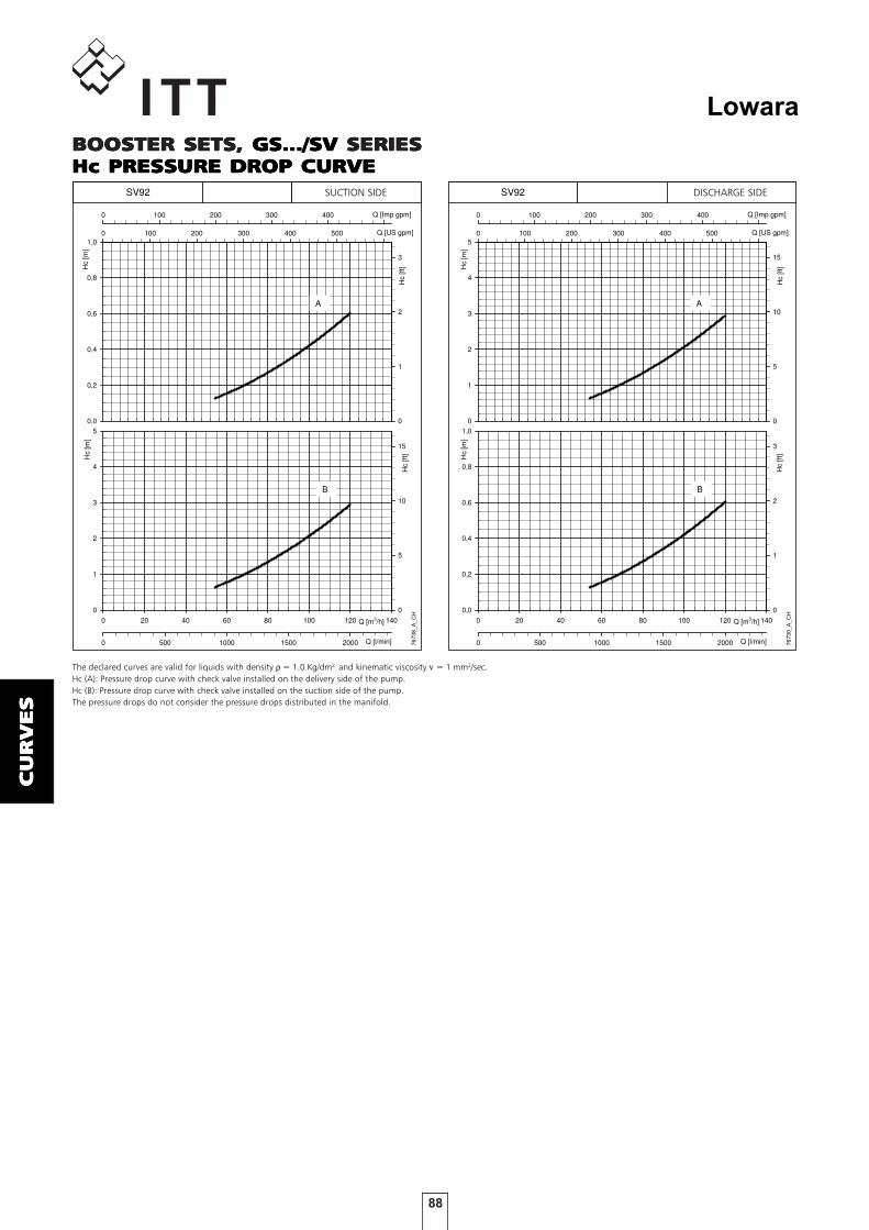
88
Lowara
CU
RV
ES
CU
RV
ES
CU
RV
ES
CU
RV
ES
CU
RV
ES
Hc
[m]
0
1
2
3
4
50 100 200 300 400 500 600
Hc
[ft]
0
5
10
15
0 100 200 300 400 500
Col 1 vs Col 2 Col 50 vs Col 51 Col 50 vs Col 51
0 20 40 60 80 100 120 140
Hc
[m]
0,0
0,2
0,4
0,6
0,8
1,0
0 500 1000 1500 2000
Hc
[ft]
0
1
2
3
7673
0_A
_CH
SV92
Q [m3/h]
Q [l/min]
Q [US gpm]
Q [Imp gpm]
A
B
Hc
[m]
0,0
0,2
0,4
0,6
0,8
1,00 100 200 300 400 500 600
Hc
[ft]
0
1
2
3
0 100 200 300 400 500
Col 1 vs Col 2 Col 50 vs Col 51 Col 50 vs Col 51
0 20 40 60 80 100 120 140
Hc
[m]
0
1
2
3
4
5
0 500 1000 1500 2000
Hc
[ft]
0
5
10
15
7673
8_A
_CH
SV92
Q [m3/h]
Q [l/min]
Q [US gpm]
Q [Imp gpm]
A
B
BOOSTER SETS,BOOSTER SETS,BOOSTER SETS,BOOSTER SETS,BOOSTER SETS, GS.../SV GS.../SV GS.../SV GS.../SV GS.../SV SERIESSERIESSERIESSERIESSERIESHc PRESHc PRESHc PRESHc PRESHc PRESSURE DROP CURVESURE DROP CURVESURE DROP CURVESURE DROP CURVESURE DROP CURVE
The declared curves are valid for liquids with density ρ = 1.0 Kg/dm3 and kinematic viscosity ν = 1 mm2/sec.Hc (A): Pressure drop curve with check valve installed on the delivery side of the pump.Hc (B): Pressure drop curve with check valve installed on the suction side of the pump.The pressure drops do not consider the pressure drops distributed in the manifold.
SUCTION SIDE DISCHARGE SIDE

89
Lowara
AC
CES
AC
CES
AC
CES
AC
CES
AC
CESSO
RIE
SSO
RIE
SSO
RIE
SSO
RIE
SSO
RIE
S
ACCESACCESACCESACCESACCESSORIESSORIESSORIESSORIESSORIES

90
Lowara
AC
CES
AC
CES
AC
CES
AC
CES
AC
CESSO
RIE
SSO
RIE
SSO
RIE
SSO
RIE
SSO
RIE
S
DIAPHRAGM TDIAPHRAGM TDIAPHRAGM TDIAPHRAGM TDIAPHRAGM TANKSANKSANKSANKSANKSThe booster sets are ready for installation, directly on the manifold, of 24-litre diaphragm tanks, one for eachpump. The sets are also equipped with caps to close off the unused couplings. Larger tanks can also be connectedto the unused end of the discharge manifold. For proper sizing of the tank please refer to the technical appendix.KitsKitsKitsKitsKits featuring the following accessories are available on requestavailable on requestavailable on requestavailable on requestavailable on request: − diaphragm tank; − on-off ball valve; − operating instructions; − packaging.
DIAPHRAGM TDIAPHRAGM TDIAPHRAGM TDIAPHRAGM TDIAPHRAGM TANK KITANK KITANK KITANK KITANK KIT
COUNTERFLANGE KITCOUNTERFLANGE KITCOUNTERFLANGE KITCOUNTERFLANGE KITCOUNTERFLANGE KIT
THREADED COUNTERFLANGESTHREADED COUNTERFLANGESTHREADED COUNTERFLANGESTHREADED COUNTERFLANGESTHREADED COUNTERFLANGES
WELDWELDWELDWELDWELD-ON COUNTERFLANGES-ON COUNTERFLANGES-ON COUNTERFLANGES-ON COUNTERFLANGES-ON COUNTERFLANGES
Manifolds up to 3" in diameter are usually supplied with threaded couplings and caps on unused end.Counterflange coupling kitsCounterflange coupling kitsCounterflange coupling kitsCounterflange coupling kitsCounterflange coupling kits made of zinc-plated or stainless steel are available on request.The counterflange kits are equipped with:
- threaded flange.- gasket and bolts/screws.- threaded counterflange (weld-on type for 3" diameter).
STANDARD DIAPHRAGM VESSEL KIT
Volume PN
Litres bar ø A B Valve Diaphragm Vessel Valve
8 8 205 390 1" FF EPDM Painted steel Nickel-plated brass
24 8 270 555 1" FF EPDM Painted steel Nickel-plated brass
24 10 270 555 1" FF EPDM Painted steel Nickel-plated brass
24 16 270 555 1" FF EPDM Painted steel Nickel-plated brass
24 10 270 575 1" FF Butyl Stainless steel AISI 316 Stainless steel
gcom-vmb_en_b_td
MaterialsDIMENSIONS (mm)
DIMENSIONI KIT CONTROFLANGE TONDE FI
KIT
TYPE DN ø C ø A B ø D H ø F N° PN
2" 50 Rp 2 125 16 165 24 18 4 25
2" ½ 65 Rp 2 ½ 145 16 185 23 18 4 16
3" 80 Rp 3 160 17 200 27 18 8 16
Gcom-ctf-tonde-f-en_a_td
DIMENSIONS (mm) HOLES
DIMENSIONI KIT CONTROFLANGE TONDE A SALDARE
KIT
TYPE DN ø C ø A B ø D ø F N° PN
2" 50 61 125 19 165 18 4 16
2"1/2 65 77 145 20 185 18 4 16
3" 80 90 160 20 200 18 8 16
4" 100 116 180 22 220 18 8 16
5" 125 141,5 210 22 250 18 8 16
6" 150 170,5 240 24 285 22 8 16
8" 200 221,5 295 26 340 22 12 16
10" 250 276,5 355 29 405 26 12 16
12" 300 327,5 410 32 460 26 12 16
Gcom-ctf-tonde-s-en_c_td
DIMENSIONS (mm) HOLES

91
Lowara
AC
CES
AC
CES
AC
CES
AC
CES
AC
CESSO
RIE
SSO
RIE
SSO
RIE
SSO
RIE
SSO
RIE
S
RUBBER EXPRUBBER EXPRUBBER EXPRUBBER EXPRUBBER EXPANSION JOINT KITANSION JOINT KITANSION JOINT KITANSION JOINT KITANSION JOINT KIT
The anti-vibrating joints or compensation joints can be used in order to absorb deformations, expansions, noises inthe piping and to reduced ram blows. Moreover they can resist a high degree of empty that allows the absorptionof negative expansions for depression.Being of elastic material it can be become deformed and be dilated facilitating therefore the installation, that itbecomes simpler and fast, also in which the piping they are not aligned. It does not need assembly joints.
L A B C D
COMPRESSIONE ESTENSIONE SPOSTAMENTO FLESSIONE ANGOLARE
COMPRESSION EXTENSION TRANSVERSE ANGULAR MOVEMENT
mm mm mm mm (°)
32 1"1/4 95 8 4 8 15
40 1"1/2 95 8 4 8 15
50 2" 105 8 5 8 15
65 2"1/2 115 12 6 10 15
80 3" 130 12 6 10 15
100 4" 135 18 10 12 15
125 5" 170 18 10 12 15
150 6" 180 18 10 12 15
200 8" 205 25 14 22 15
250 10" 240 25 14 22 15
300 12" 260 25 14 22 15
350 14" 265 25 16 22 15
400 16" 265 25 16 22 15
450 18" 265 25 16 22 15
500 20" 265 25 16 22 15
GD_JOINT_A_TD
DN
RUBBER
EXPANSION
JOINT
GIUNTI
ELASTICI
A-B-C-D non possono essere sommati A-B-C-D can not be cumulativeTABELLA 1
TABLE 1
VIBRAVIBRAVIBRAVIBRAVIBRATION DAMPERSTION DAMPERSTION DAMPERSTION DAMPERSTION DAMPERS
TYPE SHORE ø A H L M
VIBRATION DAMPER P20X20 60 20 20 18 6
VIBRATION DAMPER P40X30 60 40 30 23 8
VIBRATION DAMPER P100X50 60 100 50 50 16
Note: Available versions M/F and F/F bst-ant-piedini-en_a_td
DIMENSIONS (mm)

92
Lowara
AC
CES
AC
CES
AC
CES
AC
CES
AC
CESSO
RIE
SSO
RIE
SSO
RIE
SSO
RIE
SSO
RIE
S
DRY RUNNING PROTECTION SYSTEMSDRY RUNNING PROTECTION SYSTEMSDRY RUNNING PROTECTION SYSTEMSDRY RUNNING PROTECTION SYSTEMSDRY RUNNING PROTECTION SYSTEMSDry run shutdown systems should be installed to protect the pumps in case of insufficient water supply.
FLFLFLFLFLOOOOOAAAAAT SWITCH PROTECTION METHODT SWITCH PROTECTION METHODT SWITCH PROTECTION METHODT SWITCH PROTECTION METHODT SWITCH PROTECTION METHOD
The float switch protection system is used when the water supplycomes from open tanks. A float switch immersed in the tank isconnected to the electrical panel.If the water supply is insufficient, the float switch opens theelectric contact and the pumps stop running.
ELECTRODE PROBE PROTECTIONELECTRODE PROBE PROTECTIONELECTRODE PROBE PROTECTIONELECTRODE PROBE PROTECTIONELECTRODE PROBE PROTECTIONMETHODMETHODMETHODMETHODMETHOD
The electrode probe protection system is used when the watersupply comes from open tanks or wells. A set of three probes isconnected directly to the electronic board in the electrical panel.With the three electrodes immersed in the water, the relay on theelectronic board closes the contact, enabling the starting of thepumps. If the water supply is insufficient, the control circuitopens the electric contact and the pumps stop running.
MINIMUM PRESMINIMUM PRESMINIMUM PRESMINIMUM PRESMINIMUM PRESSURE SWITCHSURE SWITCHSURE SWITCHSURE SWITCHSURE SWITCHPROTECTION METHODPROTECTION METHODPROTECTION METHODPROTECTION METHODPROTECTION METHOD
The minimum pressure switch protection system is used when thewater supply comes from water networks or pressurized tanks.The pressure switch is connected to the electronic board in theelectrical panel.If the water supply is insufficient, the pressure switch opens theelectric contact and the pumps stop running.
Gco
m-p
ms1
_a_
dd
G
co
m-p
ms2
_a_
dd
Gco
m-p
ms3
_a_
dd

93
Lowara
TE
CH
NIC
AL
TE
CH
NIC
AL
TE
CH
NIC
AL
TE
CH
NIC
AL
TE
CH
NIC
AL
AP
PE
ND
IXA
PP
EN
DIX
AP
PE
ND
IXA
PP
EN
DIX
AP
PE
ND
IX
TECHNICALTECHNICALTECHNICALTECHNICALTECHNICALAPPENDIXAPPENDIXAPPENDIXAPPENDIXAPPENDIX

94
Lowara
TE
CH
NIC
AL
TE
CH
NIC
AL
TE
CH
NIC
AL
TE
CH
NIC
AL
TE
CH
NIC
AL
AP
PE
ND
IXA
PP
EN
DIX
AP
PE
ND
IXA
PP
EN
DIX
AP
PE
ND
IX
WATER REQUIREMENTS IN CIVIL USERS
Determination of the water requirement depends on the type of users and contemporaneity factor. The calculationmay be subject to regulations, standards or customs that may vary from country to country. The calculation methodshown below is an example based on practical experience, designed to provide a reference value and not a substi-tute for detailed analytical calculation.
Water requirements in condominiums
The consumption table shows the maximum values for each delivery point, depending on the plumbing amenities.
MAXIMUM CONSUMPTION FOR EACH DELIVERY POINT
TYPE CONSUMPTION (l/min)
Sink 9Dishwasher 10Washing machine 12Shower 12Bathtub 15Washbasin 6Bidet 6Flush tank WC 6Controlled flushing system WC 90
G-at-cm_a_th
The sum of the water consumption values of each delivery point determines the maximum theoretical re-quirement, which must be reduced according to the contemporaneity coefficient, because in actual fact thedelivery points are never used all together.
The table of water requirements in civil users shows the maximum contemporaneity flow-rate valuesbased on the number of apartments and the type of WC for apartments with one bathroom and two bath-rooms. As regards apartments with one bathroom, 7 drawing points have been taken into consideration, while 11points have been considered for apartments with two bathrooms. If the number of drawing points or apartments isdifferent, use the formulas to calculate the requirement.
( )NaNr857,0
1f
xx
=
( )NaNr857,0
1f
xx
=
( )NaNr545,0
03,1f
xx
=
( )NaNr727,0
8,0f
xx
=
Coefficient for apartments with one bathroom and flush tank WC
Coefficient for apartments with one bathroom and controlled flushing system WC
Coefficient for apartments with two bathrooms and flush tank WC
Coefficient for apartments with two bathrooms and controlled flushing system WC
f= coefficient; Nr= number of delivery points; Na= number of apartments

95
Lowara
TE
CH
NIC
AL
TE
CH
NIC
AL
TE
CH
NIC
AL
TE
CH
NIC
AL
TE
CH
NIC
AL
AP
PE
ND
IXA
PP
EN
DIX
AP
PE
ND
IXA
PP
EN
DIX
AP
PE
ND
IX
NUMBER OF
APARTMENTS 1 2 1 2
1 32 40 60 792 45 56 85 1113 55 68 105 1364 63 79 121 1575 71 88 135 1766 78 97 148 1937 84 105 160 2088 90 112 171 2239 95 119 181 23610 100 125 191 24911 105 131 200 26112 110 137 209 27313 114 143 218 28414 119 148 226 29515 123 153 234 30516 127 158 242 31517 131 163 249 32518 134 168 256 33419 138 172 263 34320 142 177 270 35221 145 181 277 36122 149 185 283 36923 152 190 290 37824 155 194 296 38625 158 198 302 39426 162 202 308 40127 165 205 314 40928 168 209 320 41729 171 213 325 42430 174 217 331 43135 187 234 357 46640 200 250 382 49845 213 265 405 52850 224 280 427 55755 235 293 448 58460 245 306 468 61065 255 319 487 63570 265 331 506 65975 274 342 523 68280 283 354 540 70485 292 364 557 72690 301 375 573 74795 309 385 589 767100 317 395 604 787120 347 433 662 863140 375 468 715 932160 401 500 764 996180 425 530 811 1056200 448 559 854 1114
For seaside resorts, a flow rate increased by at least 20% must be considered. G-at-fi_a_th
FLOW RATE (l/min)
WITH FLUSH TANK WC WITH CONTROLLED FLUSHING SYSTEM WC
TABLE OF WATER REQUIREMENTS IN CIVIL USERS

96
Lowara
TE
CH
NIC
AL
TE
CH
NIC
AL
TE
CH
NIC
AL
TE
CH
NIC
AL
TE
CH
NIC
AL
AP
PE
ND
IXA
PP
EN
DIX
AP
PE
ND
IXA
PP
EN
DIX
AP
PE
ND
IX
WATER REQUIREMENTS FOR COMMUNITY BUILDINGS
For seaside resorts, the flow rate must be increased by at least 20%.
1= Offices (N. of people)2= Department stores (N. of people)3= Nursing homes (N. of beds)4= Hotels, residences (N. of beds)
The requirements of buildings intended for specific uses, such as offices, residential units, hotels, de-partment stores, nursing homes and so on, are different from those of condominiums, and both theirglobal daily water consumption and the maximum contemporaneity flow rate are usually greater. The diagramof water requirements for community buildings shows the maximum contemporaneity flow rate ofsome types of communities, for guidance.These requirements must be determined case by case with the utmost accuracy, using analytical calculation meth-ods, according to particular needs and local provisions.

97
Lowara
TE
CH
NIC
AL
TE
CH
NIC
AL
TE
CH
NIC
AL
TE
CH
NIC
AL
TE
CH
NIC
AL
AP
PE
ND
IXA
PP
EN
DIX
AP
PE
ND
IXA
PP
EN
DIX
AP
PE
ND
IX
USE OF BOOSTER SETWater is usually delivered by public supply systems and the pressure is generally sufficient for the proper operationof the users’ water and sanitary equipment.
When this pressure is not sufficient, booster sets are employed to increase water pressure and ensure anacceptable minimum value at the furthest points. Therefore, the water supply to a building, group of buildings orto a system in general can be considered satisfactory when all the user points can deliver the required quantity ofwater.
Set connection methods (intake side)
Water can be supplied to a booster set in two ways:
1 - By installing a water storage tank between the user’s offtake and the booster set (indirect connection, fig.7.1.1).
2 - By connecting the booster set directly between the user’s offtake and the system (direct connection, fig. 7.1.1).
The indirect connection does not allow the water system pressure to be utilized. Therefore, it requires pumps withgreater head.
The direct connection allows the water system pressure to be utilized, provided the pressure fluctuation (∆ p) doesnot exceed 1 bar.
If it does, a pressure reducer must be installed for proper operation of the booster set.
fig. 7.1.1
INDIRECT
DIRECT
SUPPLY
SUPPLY
USER’S OFFTAKE
(1) BY PIPE UNDER PRESSURE WE MEAN A WATER SYSTEM, A CLOSED TANK, ETC.(2) IN THE CASE OF A WATER SYSTEM INSTALL A CHECK VALVE (A) OR A DISCONNECTING DEVICE (B), UNLESS OTHERWISE PROVIDED BY LOCAL REGULATIONS
USER’S OFFTAKE
PRESSURE REDUCERIF ∆p > Ibar
WATER PIPEUNDER
PRESSURE(1)
WATER STORAGETANK
BOOSTER SET
BOOSTER SET
UTILISATION

98
Lowara
TE
CH
NIC
AL
TE
CH
NIC
AL
TE
CH
NIC
AL
TE
CH
NIC
AL
TE
CH
NIC
AL
AP
PE
ND
IXA
PP
EN
DIX
AP
PE
ND
IXA
PP
EN
DIX
AP
PE
ND
IX
Water supply systems in civil buildingsThe configuration of the supply system must comply with the following conditions:- The minimum pressure ensuring the proper operation of the equipment must be guaranteed at the most
unfavourable drawing point (1.5 bar for valves and flush tank WC, and 2 bar for controlled flushing system WC).- At the most favourable drawing point, pressure must not exceed 5 bar.Once these parameters have been satisfied, in relation to the height of the building and to the set intakeconditions, the water supply system can have one of the following configurations:
fig. 7.1.2 fig. 7.1.3
fig. 7.1.4 fig. 7.1.5
SUPPLYSUPPLY
SUPPLY
SUPPLY
A) THE SET SERVES THE ENTIRE BUILDING
B) THE SET SERVES THE ENTIRE BUILDING, BUT THE LOWER FLOORS ARECONNECTED THROUGH A PRESSURE REDUCER SINCE THE PRESSURE TO THENEAREST UTILIZATION POINTS IS TOO HIGH
WATER PIPEUNDER PRESSURE
WATER PIPEUNDER PRESSURE
BOOSTERSET
BOOSTERSET
C) THE SET SERVES THE UPPER FLOORS, WHEREAS THE LOWER FLOORSARE SUPPLIED BY THE WATER PIPE UNDER PRESSURE
D) THIS CASE RESEMBLES THE PREVIOUS ONEEXCEPT THAT PRESSURE REDUCERS NEED TO BEINSTALLED ON SOME OF THE LOWER FLOORS

99
Lowara
TE
CH
NIC
AL
TE
CH
NIC
AL
TE
CH
NIC
AL
TE
CH
NIC
AL
TE
CH
NIC
AL
AP
PE
ND
IXA
PP
EN
DIX
AP
PE
ND
IXA
PP
EN
DIX
AP
PE
ND
IX
DETERMINING THE HEAD OF THE SET AND INTAKECONDITIONS
Level intake
The delivery head of the set (H tot) is the sum of:- He : geodetic difference in level between the set
and the furthest delivery point.- Hc : flow resistance along all the pipes and
through other system components, such as valves,filters, etc..
- Hr : pressure required at the most unfavourable point.
H tot = He+Hc+Hr
Intake with positive head
In this case, the necessary delivery head (H tot) will bereduced by the inlet pressure value (Hi).
H tot = He+Hc+Hr- Hi
Intake with negative head
When the pumps suck from an underground tank or well,the necessary head will be increased by the value of theintake height (Ha):.
H tot = He+Hc+Hr+ Ha
In this case the intake height must be considered verycarefully, bearing in mind that an excessive difference inlevel between the water storage tank and the set, or thewrong sizing of the intake pipe, can have adverse effectson pump operation, such as cavitation and unpriming.

100
Lowara
TE
CH
NIC
AL
TE
CH
NIC
AL
TE
CH
NIC
AL
TE
CH
NIC
AL
TE
CH
NIC
AL
AP
PE
ND
IXA
PP
EN
DIX
AP
PE
ND
IXA
PP
EN
DIX
AP
PE
ND
IX
The minimum operating values that can be reached at thepump suction end are limited by the onset of cavitation.
Cavitation is the formation of vapour-filled cavities withinliquids where the pressure is locally reduced to a critical value,or where the local pressure is equal to, or just below thevapour pressure of the liquid.
The vapour-filled cavities flow with the current andwhen they reach a higher pressure area the vapourcontained in the cavities condenses. The cavities collide,generating pressure waves that are transmitted to thewalls. These, being subjected to stress cycles, graduallybecome deformed and yield due to fatigue. Thisphenomenon, characterized by a metallic noiseproduced by the hammering on the pipe walls, is calledincipient cavitation.
The damage caused by cavitation may be magnified byelectrochemical corrosion and a local rise intemperature due to the plastic deformation of thewalls. The materials that offer the highest resistance toheat and corrosion are alloy steels, especially austeniticsteel. The conditions that trigger cavitation may beassessed by calculating the total net suction head,referred to in technical literature with the acronymNPSH (Net Positive Suction Head).
The NPSH represents the total energy (expressed in m.)of the liquid measured at suction under conditions ofincipient cavitation, excluding the vapour pressure(expressed in m.) that the liquid has at the pump inlet.
To find the static height hz at which to install themachine under safe conditions, the following formulamust be verified:
hp + hz ≥ (NPSHr + 0.5) + hf + hpv
where:hp is the absolute pressure applied to the free liquid surface in the suction tank, expressed in m. of liquid; hp is the quotient between the barometric pressure and the specific weight of the liquid.hz is the suction lift between the pump axis and the free liquid surface in the suction tank, expressed in m.; hz is negative when the liquid level is lower than the pump axis.hf is the flow resistance in the suction line and its accessories, such as: fittings, foot valve, gate valve, elbows, etc.hpv is the vapour pressure of the liquid at the operating temperature, expressed in m. of liquid. hpv is the quotient between the Pv vapour pressure and the liquid’s specific weight.0,5 is the safety factor.
The maximum possible suction head for installationdepends on the value of the atmospheric pressure(i.e. the elevation above sea level at which the pumpis installed) and the temperature of the liquid.
To help the user, with reference to water temperature(4° C) and to the elevation above sea level, thefollowing tables show the drop in hydraulic pressurehead in relation to the elevation above sea level, andthe suction loss in relation to temperature.
Friction loss is shown in the tables at pages 103-104 ofthis catalogue. To reduce it to a minimum, especiallyin cases of high suction head (over 4-5 m.) or withinthe operating limits with high flow rates, werecommend using a suction line having a largerdiameter than that of the pump’s suction port.It is always a good idea to position the pump as closeas possible to the liquid to be pumped.
Make the following calculation:
Liquid: water at ~15°C γ = 1 kg/dm3
Flow rate required: 30 m3/hHead for required delivery: 43 m.Suction lift: 3,5 m.The selection is an FHE 40-200/75 pump whose NPSHrequired value is, at 30 m3/h, di 2,5 m.
For water at 15 °C
hp = Pa / γ = 10,33m, hpv = Pv / γ = 0,174m (0,01701 bar)
The Hf flow resistance in the suction line with footvalves is ~ 1,2 m.By substituting the parameters in formula with thenumeric values above, we have:
10,33 + (-3,5) ≥ (2,5 + 0,5) + 1,2 + 0,17
from which we have: 6,8 > 4,4
The relation is therefore verified.
Water temperature (°C) 20 40 60 80 90 110 120
Suction loss (m) 0,2 0,7 2,0 5,0 7,4 15,4 21,5
Elevation above sea level (m) 500 1000 1500 2000 2500 3000
Suction loss (m) 0,55 1,1 1,65 2,2 2,75 3,3
NPSHNPSHNPSHNPSHNPSH
1
1

101
Lowara
TE
CH
NIC
AL
TE
CH
NIC
AL
TE
CH
NIC
AL
TE
CH
NIC
AL
TE
CH
NIC
AL
AP
PE
ND
IXA
PP
EN
DIX
AP
PE
ND
IXA
PP
EN
DIX
AP
PE
ND
IX
t T ps ρ ρ ρt T ps t T ps
°C K bar kg/dm3 °C K bar kg/dm3 °C K bar kg/dm3
0 273,15 0,00611 0,9998 55 328,15 0,15741 0,9857 120 393,15 1,9854 0,94291 274,15 0,00657 0,9999 56 329,15 0,16511 0,9852 122 395,15 2,1145 0,94122 275,15 0,00706 0,9999 57 330,15 0,17313 0,9846 124 397,15 2,2504 0,93963 276,15 0,00758 0,9999 58 331,15 0,18147 0,9842 126 399,15 2,3933 0,93794 277,15 0,00813 1,0000 59 332,15 0,19016 0,9837 128 401,15 2,5435 0,93625 278,15 0,00872 1,0000 60 333,15 0,1992 0,9832 130 403,15 2,7013 0,93466 279,15 0,00935 1,0000 61 334,15 0,2086 0,9826 132 405,15 2,867 0,93287 280,15 0,01001 0,9999 62 335,15 0,2184 0,9821 134 407,15 3,041 0,93118 281,15 0,01072 0,9999 63 336,15 0,2286 0,9816 136 409,15 3,223 0,92949 282,15 0,01147 0,9998 64 337,15 0,2391 0,9811 138 411,15 3,414 0,9276
10 283,15 0,01227 0,9997 65 338,15 0,2501 0,9805 140 413,15 3,614 0,925811 284,15 0,01312 0,9997 66 339,15 0,2615 0,9799 145 418,15 4,155 0,921412 285,15 0,01401 0,9996 67 340,15 0,2733 0,9793 155 428,15 5,433 0,912113 286,15 0,01497 0,9994 68 341,15 0,2856 0,9788 160 433,15 6,181 0,907314 287,15 0,01597 0,9993 69 342,15 0,2984 0,9782 165 438,15 7,008 0,902415 288,15 0,01704 0,9992 70 343,15 0,3116 0,9777 170 433,15 7,920 0,897316 289,15 0,01817 0,9990 71 344,15 0,3253 0,9770 175 448,15 8,924 0,892117 290,15 0,01936 0,9988 72 345,15 0,3396 0,9765 180 453,15 10,027 0,886918 291,15 0,02062 0,9987 73 346,15 0,3543 0,9760 185 458,15 11,233 0,881519 292,15 0,02196 0,9985 74 347,15 0,3696 0,9753 190 463,15 12,551 0,876020 293,15 0,02337 0,9983 75 348,15 0,3855 0,9748 195 468,15 13,987 0,870421 294,15 0,24850 0,9981 76 349,15 0,4019 0,9741 200 473,15 15,550 0,864722 295,15 0,02642 0,9978 77 350,15 0,4189 0,9735 205 478,15 17,243 0,858823 296,15 0,02808 0,9976 78 351,15 0,4365 0,9729 210 483,15 19,077 0,852824 297,15 0,02982 0,9974 79 352,15 0,4547 0,9723 215 488,15 21,060 0,846725 298,15 0,03166 0,9971 80 353,15 0,4736 0,9716 220 493,15 23,198 0,840326 299,15 0,03360 0,9968 81 354,15 0,4931 0,9710 225 498,15 25,501 0,833927 300,15 0,03564 0,9966 82 355,15 0,5133 0,9704 230 503,15 27,976 0,827328 301,15 0,03778 0,9963 83 356,15 0,5342 0,9697 235 508,15 30,632 0,820529 302,15 0,04004 0,9960 84 357,15 0,5557 0,9691 240 513,15 33,478 0,813630 303,15 0,04241 0,9957 85 358,15 0,5780 0,9684 245 518,15 36,523 0,806531 304,15 0,04491 0,9954 86 359,15 0,6011 0,9678 250 523,15 39,776 0,799232 305,15 0,04753 0,9951 87 360,15 0,6249 0,9671 255 528,15 43,246 0,791633 306,15 0,05029 0,9947 88 361,15 0,6495 0,9665 260 533,15 46,943 0,783934 307,15 0,05318 0,9944 89 362,15 0,6749 0,9658 265 538,15 50,877 0,775935 308,15 0,05622 0,9940 90 363,15 0,7011 0,9652 270 543,15 55,058 0,767836 309,15 0,05940 0,9937 91 364,15 0,7281 0,9644 275 548,15 59,496 0,759337 310,15 0,06274 0,9933 92 365,15 0,7561 0,9638 280 553,15 64,202 0,750538 311,15 0,06624 0,9930 93 366,15 0,7849 0,9630 285 558,15 69,186 0,741539 312,15 0,06991 0,9927 94 367,15 0,8146 0,9624 290 563,15 74,461 0,732140 313,15 0,07375 0,9923 95 368,15 0,8453 0,9616 295 568,15 80,037 0,722341 314,15 0,07777 0,9919 96 369,15 0,8769 0,9610 300 573,15 85,927 0,712242 315,15 0,08198 0,9915 97 370,15 0,9094 0,9602 305 578,15 92,144 0,701743 316,15 0,09639 0,9911 98 371,15 0,9430 0,9596 310 583,15 98,70 0,690644 317,15 0,09100 0,9907 99 372,15 0,9776 0,9586 315 588,15 105,61 0,679145 318,15 0,09582 0,9902 100 373,15 1,0133 0,9581 320 593,15 112,89 0,666946 319,15 0,10086 0,9898 102 375,15 1,0878 0,9567 325 598,15 120,56 0,654147 320,15 0,10612 0,9894 104 377,15 1,1668 0,9552 330 603,15 128,63 0,640448 321,15 0,11162 0,9889 106 379,15 1,2504 0,9537 340 613,15 146,05 0,610249 322,15 0,11736 0,9884 108 381,15 1,3390 0,9522 350 623,15 165,35 0,574350 323,15 0,12335 0,9880 110 383,15 1,4327 0,9507 360 633,15 186,75 0,527551 324,15 0,12961 0,9876 112 385,15 1,5316 0,9491 370 643,15 210,54 0,451852 325,15 0,13613 0,9871 114 387,15 1,6362 0,9476 374,15 647,30 221,20 0,315453 326,15 0,14293 0,9862 116 389,15 1,7465 0,946054 327,15 0,15002 0,9862 118 391,15 1,8628 0,9445
G-at_npsh_a_sc
TECHNICAL APPENDIX VAPOUR PRESSURE PS VAPOURPRESSURE AND ρ DENSITY OF WATER TABLE

102
Lowara
TE
CH
NIC
AL
TE
CH
NIC
AL
TE
CH
NIC
AL
TE
CH
NIC
AL
TE
CH
NIC
AL
AP
PE
ND
IXA
PP
EN
DIX
AP
PE
ND
IXA
PP
EN
DIX
AP
PE
ND
IX
CHOOSING ANDSIZING THESURGE TANKThe purpose of the surge tank is to limit the number of hourly startsof the pumps, placing part of its stock of water, which is maintainedunder pressure by the air above it, at the disposal of the system.
The surge tank can be of the air cushion or diaphragm type.
In the air cushion version there is no clear separation between air andwater. Since part of the air tends to mix with water, it is necessary torestore it by means of air supply units or a compressor.
In the diaphragm version, neither air supply units nor compressor areneeded, as contact between air and water is prevented by a flexiblediaphragm inside the tank.
The following method, which is used to determine the volume of asurge tank, is valid both for horizontal and vertical surge tanks.
When calculating the volume of the surge tank, it is generallysufficient to consider the first pump only.
AIR-CUSHION SURGETANKIt is determined in relation to flow rate, pump pressure, and numberof starts per hour allowed by the motor.
Va = 1,25 x Qp x (Pmax + 10)4 x Z x (Pmax - Pmin)
where:
Va = Total volume of the air-cushion surge tank in m3
Qp = Average pump flow rate in m3/hPmax = Maximum pressure setting (wcm)Pmin = Minimum pressure setting (wcm)Z = Maximum number of starts per hour allowed by the motor
Warning! By pump flow rate we mean the average between the flowrate at the maximum pressure switch setting (Qmax) and the flowrate at the minimum pressure switch setting (Qmin), i.e.:
Qp = Qmax + Qmin (m3/h)2
Example:
CN 32 - 160/22 pumpPmax = 32 mcaPmin = 22 mcaQp = 18 m3/hZ = 30
Va = 1,25 x 18 x (32 + 10) = 0,788 m3
4 x 30 x (32 - 22)
A 750-litre surge tank is therefore required.
DIAPHRAGM TANKIf you decide to use a diaphragm tank, the volume will be lower thanthat of the air-cushion tank. It can be calculated with the followingformula:
Vm = Qp x 14 x Z 1 - (Pmin - 2)
Pmax
where:
Vm = Total volume of the air-cushion surge tank in m3
Qp = Average pump flow rate in m3/hPmax = Maximum pressure setting (wcm)Pmin = Minimum pressure setting (wcm)Z = Maximum number of starts per hour allowed by the motor
Example:
CN 32 - 160/22 pumpPmax = 32 mcaPmin = 22 mcaQp = 18 m3/hZ = 30
Vm = Qp x 1 = 0,4 m3
4 x Z 1 - (Pmin - 2)Pmax
A 500-litre surge tank is therefore required.
NOMINAL CAPACITY PRESSURE SWITCH SETTINGOF AIR 1,5/2,5 2/3 2,5/3,5 3/4 3,5/4,5 4/5 4,5/5,5 5/6 5,5/6,5
CUSHION TANKNOMINAL CAPACITY OF DIAPHRAGM TANK (litres)(litres)
100 N. 2 ball types tanks/cylinder type tanks or 60 l Export tank or 100-litre tanks (Ispesl tested) table
200 100
300 200
500 300
1000 500
1500 500 + 200 500 + 300
2000 500 + 500
5002500 + 500 + 500 + 300
500
tab. 7.2.1
Approximate comparison between Lowaraair-cushion tanks and diaphragm tanks, asregards some pressure switch settingvalues
1,5/2,5 2/3 2,5/3,5 3/4 3,5/4,5 4/5 4,5/5,5 5/6 5,5/6,5 6/7
100
200
300
500
1000
1500
2000
2500
500
+
500
500
+
500
+
500
s_swp-en_a_th
500 + 200 500 + 300
PRESSURE SWITCH SETTING (bar) min/max
NOMINAL CAPACITY OF DIAPHRAGM VESSEL (litres)
NOMINAL
CAPACITY
OF AIR CUSHION
TANK
(litres)
500 + 500 + 300
N°2 ball type vessels/cylinder type vessels
or 60l Export tank or 100-litre vessels (ISPESL tested)
500 + 500
100
200
300
500

103
Lowara
TE
CH
NIC
AL
TE
CH
NIC
AL
TE
CH
NIC
AL
TE
CH
NIC
AL
TE
CH
NIC
AL
AP
PE
ND
IXA
PP
EN
DIX
AP
PE
ND
IXA
PP
EN
DIX
AP
PE
ND
IX
TABLE OF FLOW RESISTANCE IN 100 m OF STRAIGHT CASTIRON PIPELINE (HAZEN-WILLIAMS FORMULA C=100)
m3/h l/min 15 20 25 32 40 50 65 80 100 125 150 175 200 250 300 350 4001/2" 3/4" 1" 1 1/4" 1 1/2" 2 2 1/2" 3" 4" 5" 6" 7" 8" 10" 12" 14" 16"
v 0,94 0,53 0,34 0,21 0,13 hr 16 3,94 1,33 0,40 0,13 The hr values must be multiplied by:v 1,42 0,80 0,51 0,31 0,20 0.71 for galvanized or painted steel pipeshr 33,9 8,35 2,82 0,85 0,29 0.54 for stainless steel or copper pipesv 1,89 1,06 0,68 0,41 0,27 0,17 0.47 for PVC or PE pipeshr 57,7 14,21 4,79 1,44 0,49 0,16 v 2,36 1,33 0,85 0,52 0,33 0,21hr 87,2 21,5 7,24 2,18 0,73 0,25v 2,83 1,59 1,02 0,62 0,40 0,25hr 122 30,1 10,1 3,05 1,03 0,35v 3,30 1,86 1,19 0,73 0,46 0,30hr 162 40,0 13,5 4,06 1,37 0,46v 2,12 1,36 0,83 0,53 0,34 0,20hr 51,2 17,3 5,19 1,75 0,59 0,16v 2,65 1,70 1,04 0,66 0,42 0,25hr 77,4 26,1 7,85 2,65 0,89 0,25v 3,18 2,04 1,24 0,80 0,51 0,30hr 108 36,6 11,0 3,71 1,25 0,35v 3,72 2,38 1,45 0,93 0,59 0,35hr 144 48,7 14,6 4,93 1,66 0,46v 4,25 2,72 1,66 1,06 0,68 0,40hr 185 62,3 18,7 6,32 2,13 0,59v 3,06 1,87 1,19 0,76 0,45 0,30hr 77,5 23,3 7,85 2,65 0,74 0,27v 3,40 2,07 1,33 0,85 0,50 0,33hr 94,1 28,3 9,54 3,22 0,90 0,33v 4,25 2,59 1,66 1,06 0,63 0,41hr 142 42,8 14,4 4,86 1,36 0,49v 3,11 1,99 1,27 0,75 0,50 0,32hr 59,9 20,2 6,82 1,90 0,69 0,23v 3,63 2,32 1,49 0,88 0,58 0,37hr 79,7 26,9 9,07 2,53 0,92 0,31v 4,15 2,65 1,70 1,01 0,66 0,42hr 102 34,4 11,6 3,23 1,18 0,40v 5,18 3,32 2,12 1,26 0,83 0,53 0,34hr 154 52,0 17,5 4,89 1,78 0,60 0,20v 3,98 2,55 1,51 1,00 0,64 0,41hr 72,8 24,6 6,85 2,49 0,84 0,28v 5,31 3,40 2,01 1,33 0,85 0,54 0,38hr 124 41,8 11,66 4,24 1,43 0,48 0,20v 6,63 4,25 2,51 1,66 1,06 0,68 0,47hr 187 63,2 17,6 6,41 2,16 0,73 0,30v 5,10 3,02 1,99 1,27 0,82 0,57 0,42hr 88,6 24,7 8,98 3,03 1,02 0,42 0,20v 5,94 3,52 2,32 1,49 0,95 0,66 0,49hr 118 32,8 11,9 4,03 1,36 0,56 0,26v 6,79 4,02 2,65 1,70 1,09 0,75 0,55hr 151 42,0 15,3 5,16 1,74 0,72 0,34v 7,64 4,52 2,99 1,91 1,22 0,85 0,62hr 188 52,3 19,0 6,41 2,16 0,89 0,42v 5,03 3,32 2,12 1,36 0,94 0,69 0,53hr 63,5 23,1 7,79 2,63 1,08 0,51 0,27v 6,28 4,15 2,65 1,70 1,18 0,87 0,66hr 96,0 34,9 11,8 3,97 1,63 0,77 0,40v 7,54 4,98 3,18 2,04 1,42 1,04 0,80hr 134 48,9 16,5 5,57 2,29 1,08 0,56v 8,79 5,81 3,72 2,38 1,65 1,21 0,93hr 179 65,1 21,9 7,40 3,05 1,44 0,75v 6,63 4,25 2,72 1,89 1,39 1,06 0,68hr 83,3 28,1 9,48 3,90 1,84 0,96 0,32v 8,29 5,31 3,40 2,36 1,73 1,33 0,85hr 126 42,5 14,3 5,89 2,78 1,45 0,49v 6,37 4,08 2,83 2,08 1,59 1,02 0,71hr 59,5 20,1 8,26 3,90 2,03 0,69 0,28v 7,43 4,76 3,30 2,43 1,86 1,19 0,83hr 79,1 26,7 11,0 5,18 2,71 0,91 0,38v 8,49 5,44 3,77 2,77 2,12 1,36 0,94hr 101 34,2 14,1 6,64 3,46 1,17 0,48v 6,79 4,72 3,47 2,65 1,70 1,18hr 51,6 21,2 10,0 5,23 1,77 0,73v 8,15 5,66 4,16 3,18 2,04 1,42hr 72,3 29,8 14,1 7,33 2,47 1,02v 6,61 4,85 3,72 2,38 1,65 1,21hr 39,6 18,7 9,75 3,29 1,35 0,64v 7,55 5,55 4,25 2,72 1,89 1,39hr 50,7 23,9 12,49 4,21 1,73 0,82v 8,49 6,24 4,78 3,06 2,12 1,56 1,19hr 63,0 29,8 15,5 5,24 2,16 1,02 0,53v 6,93 5,31 3,40 2,36 1,73 1,33hr 36,2 18,9 6,36 2,62 1,24 0,65
G-at-pct_a_th
hr = flow resistance for 100m of straight pipeline (m)V = water speed (m/s)
420 7000
600 10000
8000480
540 9000
210 3500
360 6000
240 4000
300 5000
180 3000
2000120
150 2500
250
1500
100060
90
75 1250
500
800
600
400
90
175
48
36
24
15
10,5
18 300
30
4,2 70
3 50
150
12 200
4,8 80
0,9 15
0,6 10
5,4
1,2 20
1,8 30
2,1 35
1,5 25
2,4 40
3,6 60
6 100
7,5 125
FLOW RATE NOMINAL DIAMETER in mm and INCHES
105 1750
42 700
54 900
9

104
Lowara
TE
CH
NIC
AL
TE
CH
NIC
AL
TE
CH
NIC
AL
TE
CH
NIC
AL
TE
CH
NIC
AL
AP
PE
ND
IXA
PP
EN
DIX
AP
PE
ND
IXA
PP
EN
DIX
AP
PE
ND
IX
FLOW RESISTANCE
TABLE OF FLOW RESISTANCE IN BENDS, VALVES AND GATES
The flow resistance is calculated using the equivalent pipeline length method according to the table below:
The table is valid for the Hazen Williams coefficient C = 100 (cast iron pipework). For steel pipework, multiply thevalues by 1.41. For stainless steel, copper and coated cast iron pipework, multiply the values by 1.85.When the equivalent pipeline length has been determined, the flow resistance is obtained from the table offlow resistance.The values given are guideline values which are bound to vary slightly according to the model, especially for gatevalves and non-return valves, for which it is a good idea to check the values supplied by the manufacturers.
ACCESSORY
TYPE 25 32 40 50 65 80 100 125 150 200 250 300
45° bend 0,2 0,2 0,4 0,4 0,6 0,6 0,9 1,1 1,5 1,9 2,4 2,890° bend 0,4 0,6 0,9 1,1 1,3 1,5 2,1 2,6 3,0 3,9 4,7 5,890° smooth bend 0,4 0,4 0,4 0,6 0,9 1,1 1,3 1,7 1,9 2,8 3,4 3,9Union tee or cross 1,1 1,3 1,7 2,1 2,6 3,2 4,3 5,3 6,4 7,5 10,7 12,8Gate - - - 0,2 0,2 0,2 0,4 0,4 0,6 0,9 1,1 1,3Non return valve 1,1 1,5 1,9 2,4 3,0 3,4 4,7 5,9 7,4 9,6 11,8 13,9
G-a-pcv_a_th
DN
Equivalent pipeline length (m)

105
Lowara
TE
CH
NIC
AL
TE
CH
NIC
AL
TE
CH
NIC
AL
TE
CH
NIC
AL
TE
CH
NIC
AL
AP
PE
ND
IXA
PP
EN
DIX
AP
PE
ND
IXA
PP
EN
DIX
AP
PE
ND
IX100
200 LOW 5
300
500 LOW 10
700
1000
1500
2000
2500 LOW 25
3000
4000 LOW 40
5000
6000
Air supply unitThe most commonly used air supply unit model is the “depression” type, which uses the depression produced bythe pump suction.
fig. 7.2.2 - The air supply unit consists of a body made of plasticmaterial suitable for foodstuffs (1), a spherical rubbershutter (2), an upper brass union (3) with an air valve (4),a Venturi tube (5), and a flexible pipe (6) to be connectedto the pump intake.
fig. 7.2.5 - The air accumulated inside the body pushes the rubberball (2) to the bottom, thus blocking the passage. At thispoint the valve closes and the rubber ball prevents the airaccumulated inside the body of the air supply unit fromreaching the pump intake.
Air supply unit operation
fig. 7.2.3 - When the pump starts up, the intake pressure is lowerthan the pressure in the surge tank. This differencecauses water to flow from the surge tank to the pumpintake, through the air supply unit.
fig. 7.2.6 - When the pump stops the depression ceases and a flowof water is produced, which lifts the ball and pushes theair in the body of the supply unit into the tank.
fig. 7.2.4 - The flow of water that passes through theVenturi tube (5) generates a depression andallows the opening of the air valve (4). As aconsequence, air enters the body of the supplyunit.
Air supply unit selection tankTANK AVERAGE PRESSURE SETTING
CAPACITYbar
L 2,5 3,5 4,5 5,5 6,5 7,5
tab. 7.2.7
This cycle is repeated each time the pump starts up until the required quantity of air has accumulated. To ensure proper system operation, nocheck valve must be mounted between the pump delivery outlet and the surge tank, as it would impede the return flow of water through thepump.
2.5 3.5 4.5 5.5 6.5 7.5
100
200
300
500
700
1000
1500
2000
2500
3000
4000
5000
6000
g_air-en_a_th
TABELLA PER LA SCELTA DELL'ALIMENTATORE D'ARIA
TANK
CAPACITY
L
AVERAGE PRESSURE SETTING
bar
LOW 40
LOW 5
LOW 10
LOW 25
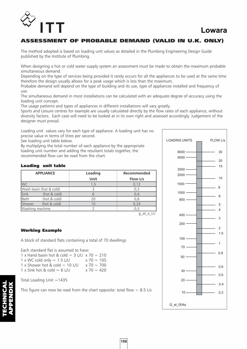
106
Lowara
TE
CH
NIC
AL
TE
CH
NIC
AL
TE
CH
NIC
AL
TE
CH
NIC
AL
TE
CH
NIC
AL
AP
PE
ND
IXA
PP
EN
DIX
AP
PE
ND
IXA
PP
EN
DIX
AP
PE
ND
IX
ASSESSMENT OF PROBABLE DEMAND (VALID IN U.K. ONLY)
The method adopted is based on loading unit values as detailed in the Plumbing Engineering Design Guidepublished by the Institute of Plumbing.
When designing a hot or cold water supply system an assessment must be made to obtain the maximum probablesimultaneous demand.Depending on the type of services being provided it rarely occurs for all the appliances to be used at the same timetherefore the design usually allows for a peak usage which is less than the maximum.Probable demand will depend on the type of building and its use, type of appliances installed and frequency ofuse.The simultaneous demand in most installations can be calculated with an adequate degree of accuracy using theloading unit concept.The usage patterns and types of appliances in different installations will vary greatly.Sports and Leisure centres for example are usually calculated directly by the flow rates of each appliance, withoutdiversity factors. Each case will need to be looked at in its own right and assessed accordingly. Judgement of thedesigner must prevail.
Loading unit values vary for each type of appliance. A loading unit has noprecise value in terms of litres per second. See loading unit table below.By multiplying the total number of each appliance by the appropriateloading unit number and adding the resultant totals together, therecommended flow can be read from the chart.
Loading unit table
Working Example
A block of standard flats containing a total of 70 dwellings
Each standard flat is assumed to have: 1 x Hand basin hot & cold = 3 L/U x 70 = 2101 x WC cold only = 1.5 L/U x 70 = 1051 x Shower hot & cold = 10 L/U x 70 = 7001 x Sink hot & cold = 6 L/U x 70 = 420
Total Loading Unit =1435
This figure can now be read from the chart opposite: total flow = 8.5 L/s
APPLIANCE Loading Recommended
Unit Flow L/sWC 1,5 0,12Wash basin (hot & cold) 3 0,3Sink (hot & cold) 6 0,4Bath (hot & cold) 20 0,6Shower (hot & cold) 10 0,24Washing machine 2 0,3
g_at_a_LU
0.3
0.4
0.5
0.6
2
0.8
1
1.5
3
4
5
6
20
8
10
15
30
10
20
30
100
50
70
200
400
800
1000
5000
1500
2000
3000
8000
G_at_004a
LOADING UNITS FLOW L/s

107
Lowara
TE
CH
NIC
AL
TE
CH
NIC
AL
TE
CH
NIC
AL
TE
CH
NIC
AL
TE
CH
NIC
AL
AP
PE
ND
IXA
PP
EN
DIX
AP
PE
ND
IXA
PP
EN
DIX
AP
PE
ND
IX
ASSESSING HEAD REQUIREMENT (VALID IN U.K. ONLY)
The head required in a boosted cold water system consists of three components, static head, residual pressureand system friction losses. The values of these three components are added together to give the total requiredhead at the system flow rate.
Static head (He): This is the difference between the breaktank low water line and the highest discharge point in thebuilding. If the height of the build is not known, then 2.8-3.0metres per floor can be used to assess the building height.
Residual pressure (Hr): This is the pressure required at thehighest outlet device, normally 20metres. Note: some modern showers may require higher pressures.
System friction losses (Hc): The total losses throughpipework, pipework fittings, valves, PRVs and all otherequipment fed through the pumpset must be added to find thetotal system losses.On conventional systems that do not include excessive runs ofpipe or specialised components a rough guide would be to allow0.05 metres friction loss for each metre of static head.
Example:Static head (He): Building height four floors @ 2.8m each = 11.2m +Residual pressure (Hr): Pressure at highest outlet = 20m +Friction loses (Hc): 11.2 (static head) x 0.05 = 0.56mTotal pump head required (H) = 31.76m (3.11 Bar)
Pressure limitationsThe designer must ensure that adequate precautions are taken to ensure that the system is capable ofwithstanding the closed valve head produced by the pump set. In cases where closed valve pressures cannot betolerated, pressure reducing valvesshould be fitted down stream ofthe booster set.
VelocityPipework within the system shouldbe sized to limit the velocity to thefigures stated in table below.Higher velocities will lead toexcessive noise, wear and higherrunning costs.
BOOSTER SIZING
What information do we require to size a booster set?
• As a minimum we need to know:– The total flow rate, or information to assess this.– The total head at flow rate, or the height of building.– If the pumps are to operate under positive head, or suction lift conditions.– Where the set is to be sited, I.E. basement or roof.– Preferred choice fixed of variable speed
• Additional information if available:– How to split the duty for particular applications I.E. duty/standby or duty/assist.– The size and material of the connecting pipework.– Is a Jockey pump required.
Hc
H
Hr
He
G_at_005_a
PIPE SIZE SUCTION PIPE DELIVERY PIPE
m/s m/sLess than 80mm 0,46 0,91 to 1,07100-150mm 0,55 1,22 to 1,52200mm 0,76 1,68250 and above 0,91 1,82 to 2,13
g_at_a_fs

108
Lowara
TE
CH
NIC
AL
TE
CH
NIC
AL
TE
CH
NIC
AL
TE
CH
NIC
AL
TE
CH
NIC
AL
AP
PE
ND
IXA
PP
EN
DIX
AP
PE
ND
IXA
PP
EN
DIX
AP
PE
ND
IX
FLOAT SWITCHES
VALVES CYLINDER WATER TANK
NON-RETURN VALVES COUPLINGS
AIR SUPPLY UNITS
ACCESACCESACCESACCESACCESSORIESSORIESSORIESSORIESSORIES
PRESSURE TRANSMITTER

109
Lowara
TE
CH
NIC
AL
TE
CH
NIC
AL
TE
CH
NIC
AL
TE
CH
NIC
AL
TE
CH
NIC
AL
AP
PE
ND
IXA
PP
EN
DIX
AP
PE
ND
IXA
PP
EN
DIX
AP
PE
ND
IX
VOLUMETRIC CAPACITYVOLUMETRIC CAPACITY
Litres Cubic metres Cubic feet Cubic feet Imp. gal. US gal.
per minute per hour per hour per minute per minute per minute
l/min m3/h ft
3/h ft
3/min Imp. gal/min Us gal./min
1,0000 0,0600 2,1189 0,0353 0,2200 0,2642
16,6667 1,0000 35,3147 0,5886 3,6662 4,4029
0,4719 0,0283 1,0000 0,0167 0,1038 0,1247
28,3168 1,6990 60,0000 1,0000 6,2288 7,4805
4,5461 0,2728 9,6326 0,1605 1,0000 1,2009
3,7854 0,2271 8,0208 0,1337 0,8327 1,0000
PRESSURE AND HEAD
Newton per kilo Pascal bar Pound force per metre millimetre of
square metre square inch of water mercury
N/m2 kPa bar psi m H2O mm Hg
1,0000 0,0010 1 x 10⁻⁵ 1.45 x 10⁻⁴ 1.02 x 10⁻⁴ 0,0075
1000,0000 1,0000 0,0100 0,1450 0,1020 7,5006
1 x 10⁵ 100,0000 1,0000 14,5038 10,1972 750,0638
6894,7570 6,8948 0,0689 1,0000 0,7031 51,7151
9806,6500 9,8067 0,0981 1,4223 1,0000 73,5561
133,3220 0,1333 0,0013 0,0193 0,0136 1,0000
LENGTH
millimetre centimetre metre inch foot yard
mm cm m in ft yd
1,0000 0,1000 0,0010 0,0394 0,0033 0,0011
10,0000 1,0000 0,0100 0,3937 0,0328 0,01091000,0000 100,0000 1,0000 39,3701 3,2808 1,0936
25,4000 2,5400 0,0254 1,0000 0,0833 0,0278
304,8000 30,4800 0,3048 12,0000 1,0000 0,3333
914,4000 91,4400 0,9144 36,0000 3,0000 1,0000
VOLUMEVOLUME
cubic metre litre millilitre imp. Gallon US gallon cubic foot
m3 litro ml imp. gal. US gal. ft
3
1,0000 1000,0000 1 x 10⁶ 219,9694 264,1720 35,3147
0,0010 1,0000 1000,0000 0,2200 0,2642 0,0353
1 x 10⁻⁶ 0,0010 1,0000 2.2 x 10⁻⁴ 2.642 x 10-43.53 x 10
-5
0,0045 4,5461 4546,0870 1,0000 1,2009 0,1605
0,0038 3,7854 3785,4120 0,8327 1,0000 0,1337
0,0283 28,3168 28316,8466 6,2288 7,4805 1,0000
G-at_pp-en_a_sc
VVVVVOLOLOLOLOLUMETRIC CAPUMETRIC CAPUMETRIC CAPUMETRIC CAPUMETRIC CAPACITYACITYACITYACITYACITY
PRESPRESPRESPRESPRESSURE AND HEADSURE AND HEADSURE AND HEADSURE AND HEADSURE AND HEAD
LENGLENGLENGLENGLENGTHTHTHTHTH
VVVVVOLOLOLOLOLUMEUMEUMEUMEUME

110
Lowara
TE
CH
NIC
AL
TE
CH
NIC
AL
TE
CH
NIC
AL
TE
CH
NIC
AL
TE
CH
NIC
AL
AP
PE
ND
IXA
PP
EN
DIX
AP
PE
ND
IXA
PP
EN
DIX
AP
PE
ND
IX


Lowara
Headquarters
LOWARA S.r.l. UnipersonaleVia Dott. Lombardi, 1436075 Montecchio MaggioreVicenza - ItalyTel. (+39) 0444 707111Fax (+39) 0444 492166e-mail: [email protected]: //www.lowara.com
ITT RESIDENTIAL AND COMMERCIAL WATER DIVISION - EMEA
For additional addresses, please visitwww.lowara.com
Lowara reserves the right to make modificationswithout prior notice.
AUSTRIAITT AUSTRIA GmbHA-2000 STOCKERAUErnst Vogel-Straße 2Tel. (+43) 02266 604Fax (+43) 02266 65311e-mail: [email protected]://www.ittaustria.com
FRANCEITT FRANCEParc de l'ile29 rue du Port92022 Nanterre CedexTel. (+33) 02 47 88 17 17Fax (+33) 02 47 88 17 00e-mail: [email protected]://www.lowara.fr
GERMANYITT LOWARA DEUTSCHLAND GmbHBiebigheimer Straße 12D-63762 GroßostheimTel. (+49) 0 60 26 9 43 - 0Fax (+49) 0 60 26 9 43 - 2 10e-mail: [email protected]://www.lowara.de
IRELANDITT IRELAND50 Broomhill CloseAirton RoadTallaghtDUBLIN 24Tel. (+353) 01 4524444Fax (+353) 01 4524795e-mail: [email protected] -http://www.lowara.ie
NEDERLANDLOWARA NEDERLAND B.V.Zandweistraat 224181 CG WaardenburgTel. (+31) 0418 65 50 60Fax (+31) 0418 65 50 61e-mail: [email protected]://www.lowara.nl
POLANDLOWARA VOGEL POLSKA Sp. z o.o.PL 57-100 Strzelinul. Kazimierza Wielkiego 5Tel. (+48) 071 769 3900 - Fax (+48) 071 769 3909e-mail: [email protected] -http://www.lowara-vogel.pl
PORTUGALITT PORTUGAL, LdaPraçeta da Castanheira, 384475-019 BarcaTel. (+351) 22 9478550Fax (+351) 22 9478570e-mail: [email protected]://www.itt.pt
RUSSIALOWARA RUSSIAKalanchevskaya st. 11 b.2, off. 334107078 MoscowTel. (+7) 495 631 55 15Fax (+7) 495 631 59 [email protected] - www.lowara.ru
UKLOWARA UK LTD.Millwey Rise, Industrial EstateAxminster - Devon EX13 5HU UKTel. (+44) 01297 630200Fax (+44) 01297 630270e-mail: [email protected]://www.lowara.co.uk
cod. 191000001 P 04/10
ITT-Lowara (www.lowara.com), headquarters of "Residential and CommercialWater - EMEA" part of the ITT Corporation and located in Montecchio Maggiore,Vicenza - Italy, is a leading manufacturer of hydraulic pumps and water handlingand control systems. It has 1.819 employees in Europe, 675 operating in Italy. In2009 its consolidated sales totalled about 286 million € , or over 396 million $.ITT Corporation is a high-technology engineering and manufacturing companyoperating on all seven continents in three vital markets: water and fluidsmanagement, global defense and security, and motion and flow control. With aheritage of innovation, ITT partners with its customers to deliver extraordinarysolutions that create more livable environments, provide protection and safety andconnect our world. Headquartered in White Plains, N.Y., the company generated2009 revenue of $10.9 billion.
cod. 191000501 W 10/10