gsa progressive collapse design guidelines applied to ... · gsa progressive collapse design...
TRANSCRIPT

1
GSA Progressive Collapse DesignGuidelines Applied toConcrete Moment-ResistingFrame Buildings
David N. Bilow, P.E., S.E. andMahmoud E. Kamara, PhDPortland Cement Association
Tri-Service Infrastructure SystemsConference & ExpositionSt. Louis, MO - August 2005

2
TopicsTopics
►►DefinitionDefinition►►Comparison of DOD & GSA requirementsComparison of DOD & GSA requirements►►Purpose of PCA studyPurpose of PCA study►►Study procedureStudy procedure►►ResultsResults

3
Ronan PointRonan Point(1968)(1968)
►► Explosion on 18Explosion on 18thth
floorfloor►► Wall panel blownWall panel blown
outout►► 22 floors collapse22 floors collapse

4
Ronan PointRonan Point

5
PreventPreventProgressiveProgressiveCollapseCollapse
►► Explosion at groundExplosion at groundfloorfloor
►► Local damage onlyLocal damage only

6
GSA and DOD Criteria Comparison
Middle of long side,middle of short side, &corner column, at eachfloor one at a time
Middle of long side,middle of short side, &corner column, atground level only
ColumnRemoval
Req’d for Low LOP w/overtical tie, Medium LOP,& High LOP
Required fornonexempt
Alternate PathAnalysis
Vertical and/or horizontaltie forces, and ductility
Redundancy, ductility& continuity
TieRequirements
Very Low, Low, Medium,and High
Exempt or nonexemptLevel ofProtection(LOP)
DODGSARequirement

7
Comparison
Linear static, nonlinear static,or nonlinear dynamic
Linear staticpreferred
Method ofAnalysis
1.0DL + 0.5LLRecommendedUpward Loads onFloor Slabs
1.2DL + 0.5LL + 0.2WDL + 0.25LLLoads forDynamic Analysis
2.0(1.2DL + 0.5LL) + 0.2WAdjacent bays & floor above
1.2 DL + 0.5LL for rest ofstructure
2(DL +0.25LL)all bays andfloors
Loads forStatic Analysis
DODGSARequirement

8
Comparison
Exterior: 1500 ft2
or 15%Interior: 3000 ft
2or 30%
Exterior: 1800 ft2
Interior: 3600 ft2
Maximum Extent ofFloor Collapse
Allow plastic hinges &moment redistribution
DCR ≤ 2.0 fortypical structures
Acceptance Criteria
φ specified in ACI 3181Strength ReductionFactor, φ
1.251.25Material StrengthIncrease Factor
DODGSARequirement

9
PCA Study ObjectivesPCA Study Objectives
1. Determine how to apply the GSAprogressive collapse guidelines.
2. Determine additional reinforcementneeded to meet requirements forreinforced concrete frame buildings.

10
ReferencesReferences
►► General Services AdministrationGeneral Services AdministrationProgressive CollapseProgressive CollapseAnalysis and Design Guidelines forAnalysis and Design Guidelines forNew Federal Office Buildings andNew Federal Office Buildings andMajor Modernization ProjectsMajor Modernization ProjectsJune 2003June 2003
►► 2000 International Building Code2000 International Building Code►► ACI 318ACI 318--99 Building Code Requirements for99 Building Code Requirements for
Structural ConcreteStructural Concrete

11
Study Procedure
1. Design 3 building structures for live,dead, wind, and seismic loads
2. Instantaneously remove selected firstfloor columns
3. Calculate the alternate path loads perGSA criteria
4. Apply the GSA loads to the structure5. Determine moments and forces6. Determine ultimate unfactored member
capacity7. Calculate Demand Capacity Ratios8. Calculate additional reinforcement
12
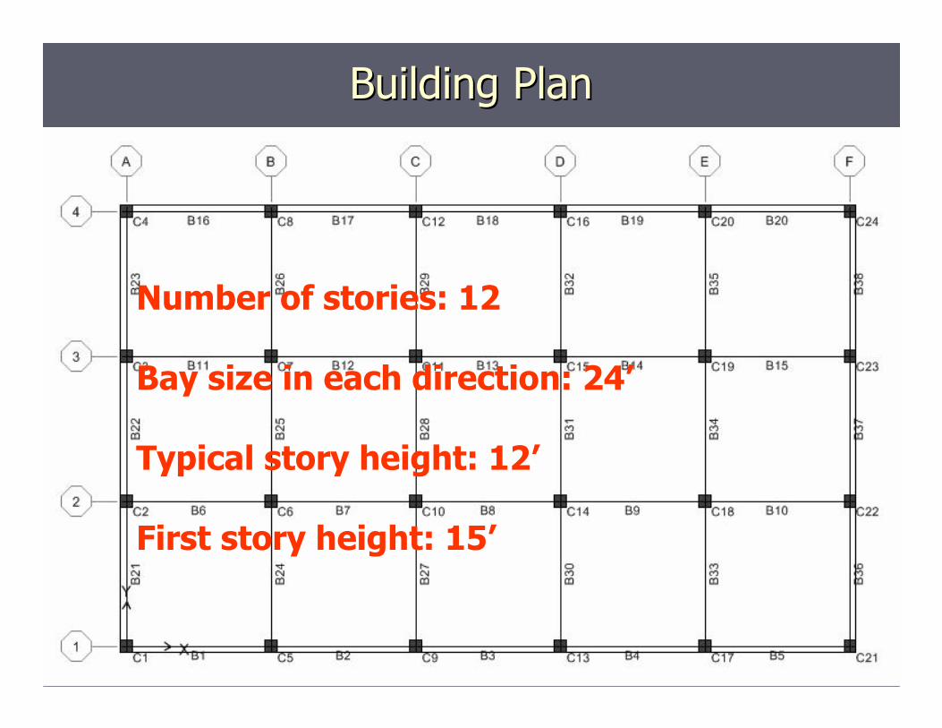
Building PlanBuilding Plan
Number of stories: 12
Bay size in each direction: 24’
Typical story height: 12’
First story height: 15’

13
LoadsLoads
►►Floor Live Load = 50 psfFloor Live Load = 50 psf►►Superimposed Dead Load = 30 psfSuperimposed Dead Load = 30 psf►►Dead LoadDead Load►►Wind Load for 70 MPHWind Load for 70 MPH►►Seismic LoadSeismic Load -- 3 Locations3 Locations

14
Three Reinforced Cast-in-Place Concrete
Moment Frame Buildings
Special momentframe
.61gD
Intermediatemoment frame
.094gC
Ordinary momentframe
.024gA
Type of DetailingShort PeriodAcceleration
SeismicDesign Class

15
Load Combinations
Normal Loading►U = 1.4D + 1.7L►U = 0.75(1.4D + 1.7L+ 1.7W)►U = 0.75(1.4D +1.7L +1.1 E)

16
Analysis and DesignAnalysis and Design
►► Select preliminary member sizesSelect preliminary member sizes►► Model in 3 dimensionsModel in 3 dimensions►► Static linear elastic analysisStatic linear elastic analysis►► Beam and column reinforcement calculatedBeam and column reinforcement calculated►► ETABS software version 8.11ETABS software version 8.11

17
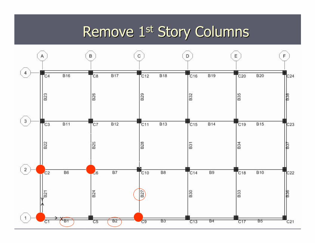
Remove 1Remove 1stst Story ColumnsStory Columns
Interior columnremoved for
parking and publicspace
18
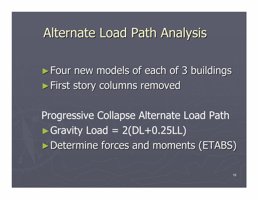
Alternate Load Path AnalysisAlternate Load Path Analysis
►►Four new models of each of 3 buildingsFour new models of each of 3 buildings►►First story columns removedFirst story columns removed
Progressive Collapse Alternate Load Path►Gravity Load = 2(DL+0.25LL)►►Determine forces and moments (ETABS)Determine forces and moments (ETABS)

19
Bending Moments
After Removing LongSide Center Column
After RemovingCorner Column
X X

20
Shear ForcesShear Forces
After Removing LongSide Center Column
X

21
Calculate Demand Capacity Ratios
DCR = QUD/QCE
QUD: Acting force from alternate load path
QCE: Ultimate unfactored componentcapacity with strength increased 25%
Limits:DCR < 2.0 for typical structuresDCR < 1.5 for atypical structures
NEHRP Guidelines for Seismic Rehabilitation ofNEHRP Guidelines for Seismic Rehabilitation ofBuildingsBuildings-- FEMA 1997FEMA 1997
22
Remove 1Remove 1stst Story ColumnsStory Columns
23
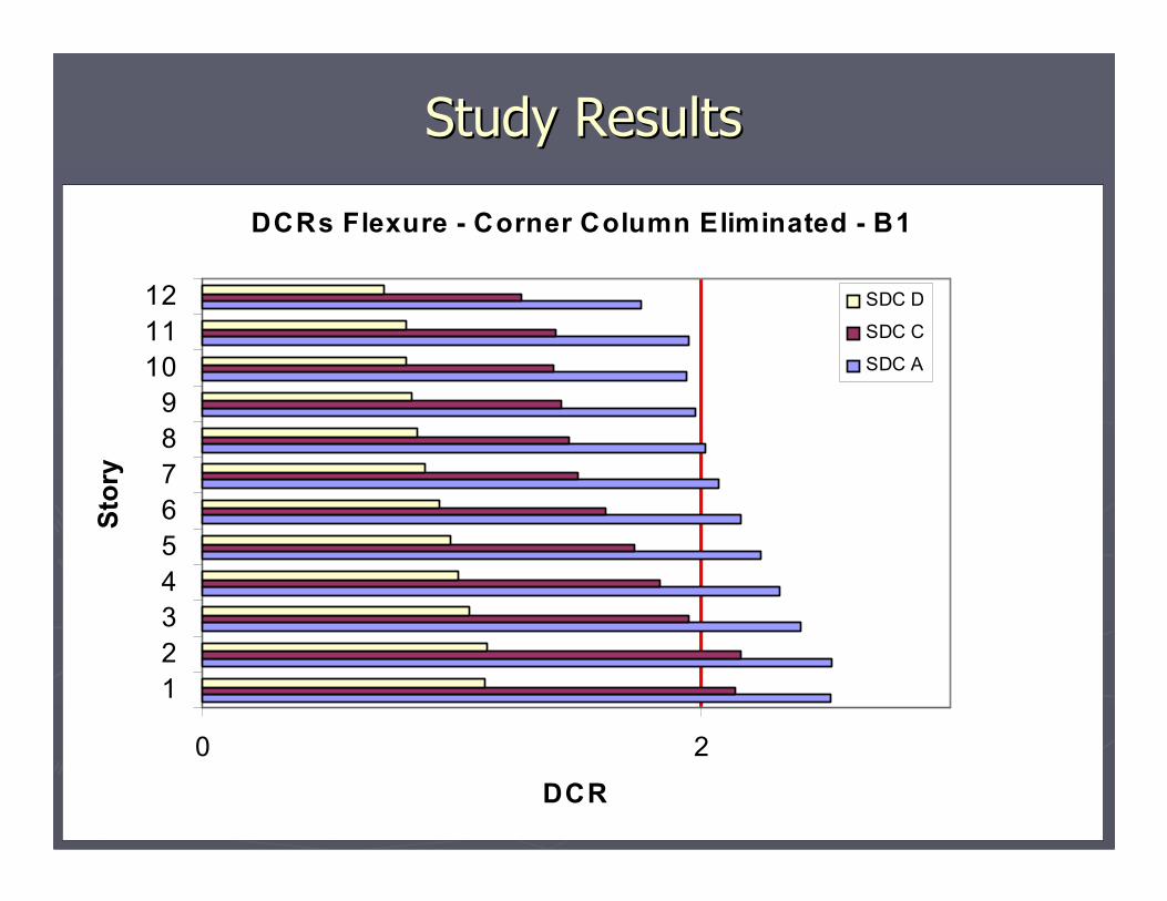
DCRs Flexure - Corner Column Eliminated - B1
0 2
123456789
101112
Stor
y
DCR
SDC D
SDC C
SDC A
Study ResultsStudy Results

24
DCRs Flexure - Long Side Column Eliminated -B2
0 2
123456789
101112
Stor
y
DCR
SDCD
SDCC
SDCA
ResultsResults
25
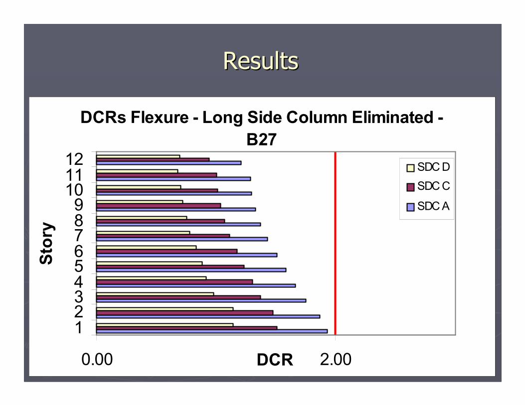
DCRs Flexure - Long Side Column Eliminated -B27
0.00 2.00
123456789
101112
Stor
y
DCR
SDC DSDC C
SDC A
ResultsResults

26
DCR for Shear in BeamsDCR for Shear in Beams
1.041.041.461.4611
1.011.011.391.3933
.94.941.321.3255
.86.861.231.2377
.81.811.191.1999
.79.791.171.171111
B27B27B2B2StoryStory

27
Remove 1Remove 1stst Story ColumnsStory Columns

28
DCR for 1DCR for 1stst Story ColumnsStory Columns
.44.44.65.65.84.84C12C12
.59.59.76.761.021.02C11C11
.73.73.88.881.231.23C10C10
XXXXXXC9C9
SeismicSeismicClass DClass D
SeismicSeismicClass CClass C
SeismicSeismicClass AClass A
ColumnColumn

29
Summary of Results
235 of456
55 of 456AllAllAll
Number
Add Rebar> 2.0Beams, Class AAdd Rebar> 2.0Beams, Class C
None< 2.0Beams, Class DNone< 2.0ColumnsNone< 2.0ShearActionDCR ValueItem
Additional rebar for “A” StructuresCost = $12,000

30
Applying the GSA criteria to preventprogressive collapse for concrete
buildings can be accomplished by thestructural engineer using readily
available software and for little additionalconstruction cost.
ConclusionConclusion

31
Contact InformationContact Information
David N. Bilow, P.E., S.E.David N. Bilow, P.E., S.E.Portland Cement AssociationPortland Cement [email protected]@cement.org847847--972972--90649064847847--972972--9065 Fax9065 Fax5420 Old Orchard Road5420 Old Orchard RoadSkokie, IL 60077Skokie, IL 60077