gsm-2 datamanager manual - keller america · gsm-2 datamanager manual version 2.3.3, june 2010....
TRANSCRIPT

GSM-2 Datamanager ManualVersion 2.3.3, June 2010

Datamanager www.keller-druck.com
www.keller-druck.com
Index
1 Environment
........................................................................................................................................................................................ 4 1.1 Principle of Data Management ................................................................................................................................. 4
2 First Start .................................................................................................................................................................... 5
3 GSM Module Configuration ...................................................................................................................................... 9 3.1 Status Symbols ...................................................................................................................................................... 11 3.2 Calculations ............................................................................................................................................................ 12 3.3 Remote Configuration of Water Level, Overflow and Calculation ......................................................................... 15 3.4 Water Level Configuration ..................................................................................................................................... 15 3.5 (Over)Flow Configuration ....................................................................................................................................... 16 3.6 Message Forwarding .............................................................................................................................................. 17 3.7 Data Request ......................................................................................................................................................... 19
4 Email Configuration ...................................................................................................................................................................................... 20
5 Additional Settings .................................................................................................................................................. 23 5.1 General Configuration ............................................................................................................................................ 23
6 Export Data .............................................................................................................................................................. 26
7 Features of the Datamanager ................................................................................................................................. 30 7.1 Import Measurements from IDC/DX5-Files ............................................................................................................ 30 7.2 Silent Mode ............................................................................................................................................................ 31 7.3 Calculator ............................................................................................................................................................... 31 7.4 Manual Parser ........................................................................................................................................................ 32 7.5 Manual Data Maintenance - Deleting Data Sets ................................................................................................... 33 7.6 Delete Locations ................................................................................................................................................... 35 7.7 Restore Locations ...................................................................................................................................................................................... 36 7.8 User Administration ................................................................................................................................................ 38 7.9 Login ....................................................................................................................................................................... 38 7.10 Database Backup/Recovery ................................................................................................................................ 39
8 GSM Terminal Configuration ................................................................................................................................. 40
9 Differences between GSM-1 and GSM-2 ............................................................................................................... 44
10 Database ................................................................................................................................................................. 45 10.1 Installing MySQL .................................................................................................................................................. 45 10.2 Installing the Database Server (Windows) .......................................................................................................... 45
Operating Manual 02-2010 Page 2/48
Datamanager www.keller-druck.com
11 Index of Figures
Number Title Page ...................................................................................................................................................................................... 46
Operating Manual 02-2010 Page 3/48

Datamanager www.keller-druck.com
1 Environment
Figure [1] Environment of the GSM-2 Datamanager
The device installed in the field is called a GSM module. A location is a virtual GSM module in the Datamanager representing the real GSM module, including configuration, calculations and forwarding.
1.1 Principle of Data Management
Figure [2] Principle of data management
The Datamanager receives and collects the raw data sent by the GSM modules and stores the raw data in a data -base. Each raw data value (measuring channel) is individually adjustable (calibration). Such calibration consists of a factor and an offset allowing the user to customize its influence on the raw data. The default values for the factor is "1" and for the offset "0".
Calculation: Calibrated Value = Raw Data Value * Factor + Offset
"Scaling" works the same as "Calibration", but its purpose is to convert the channel values into different units.
Operating Manual 02-2010 Page 4/48

Datamanager www.keller-druck.com
2 First Start
When the Datamanager is started for the first time, the application will guide you through the basic configuration steps required for proper operation. The desired database should be selected at the start of the basic configuration process. The Datamanager supports two types of database storage concepts: SQLite and MySQL.
SQLite is a software library that implements a self-contained, server-less, zero-configuration, transactional SQL database engine.MySQL is a relational database management system (RDBMS) that runs as a server providing multi-user access to a number of databases.
By default the Datamanager uses the SQLite database engine to store all information (see 2 ). We intentionally set the default selection to this database concept to simplify the installation of the Datamanager for the user, as no database server installation is required. SQLite is a lean solution for measuring applications with only a few GSM-2 modules and where only small to medium-sized data storage requirements are anticipated. SQL-ite is also suitable for a single stand-alone PC solution.
Operating the Datamanager in connection with MySQL requires the installation of or accessibility to a MySQL serv-er (e.g. running on a network server). For more instructions concerning the installation of a MySQL server please refer to Section 10.1. MySQL is the recommended database system for operating the Datamanager at a professional level. MySQL should be the preferred choice if you are planning to establish a larger GSM-2 measuring network or if you expect a high volume of raw data to be stored whilst monitoring the GSM-2 modules out in the field. We recommend MySQL due to better database administration and maintenance facilities with respect to reliable data back-up and integration into an existing IT environment.
The first system start and basic configuration process is divided up into several steps. The very first dialog outlines the question which database concept should be applied. The Default setting is the lean SQLite; the Custom setting will guide you through the access data configuration process for an up-and-running running MySQL server (see 2).
Figure [3] First start database concept and language selection.
2. Select the desired language
Figure [4] Custom configuration of MySQL server access and test of the connection to the server.
(custom configuration only)
1. For Server-Host you may use "localhost" which means that the MySQL server is running on the same PC where the Datamanager was installed. Server-Host can, of course, be any valid IP address or DNS name where the mySQL server is accessible.
2. Press the "Test" button to verify the access data set-tings. Datamanager then tries to establish the connec-tion to the MySQL server.
Operating Manual 02-2010 Page 5/48
Datamanager www.keller-druck.com
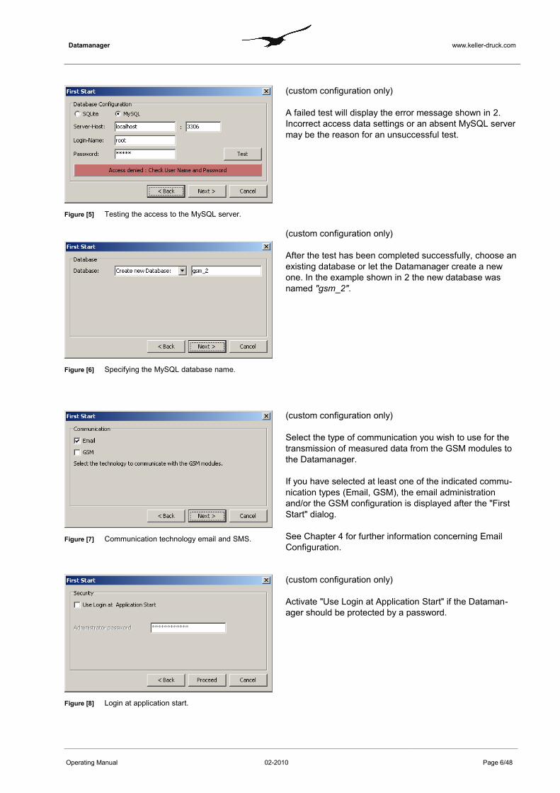
Figure [5] Testing the access to the MySQL server.
Figure [6] Specifying the MySQL database name.
(custom configuration only)
A failed test will display the error message shown in 2. Incorrect access data settings or an absent MySQL server may be the reason for an unsuccessful test.
(custom configuration only)
After the test has been completed successfully, choose an existing database or let the Datamanager create a new one. In the example shown in 2 the new database was named "gsm_2".
Figure [7] Communication technology email and SMS.
(custom configuration only)
Select the type of communication you wish to use for the transmission of measured data from the GSM modules to the Datamanager.
If you have selected at least one of the indicated commu-nication types (Email, GSM), the email administration and/or the GSM configuration is displayed after the "First Start" dialog.
See Chapter 4 for further information concerning EmailConfiguration.
Figure [8] Login at application start.
(custom configuration only)
Activate "Use Login at Application Start" if the Dataman-ager should be protected by a password.
Operating Manual 02-2010 Page 6/48
Datamanager www.keller-druck.com
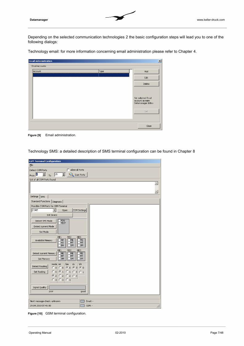
Depending on the selected communication technologies 2 the basic configuration steps will lead you to one of the following dialogs:
Technology email: for more information concerning email administration please refer to Chapter 4.
Figure [9] Email administration.
Technology SMS: a detailed description of SMS terminal configuration can be found in Chapter 8
Figure [10] GSM terminal configuration.
Operating Manual 02-2010 Page 7/48

Datamanager www.keller-druck.com
After "First Start" is completed, the Datamanager shows the following main window:
Figure [11] Datamanager main window.
If an email account is configured, the Datamanager will now receive messages (configurations and data) from the GSM modules. Additional settings can now be made in the Datamanager.
Operating Manual 02-2010 Page 8/48
Datamanager www.keller-druck.com
3 GSM Module Configuration
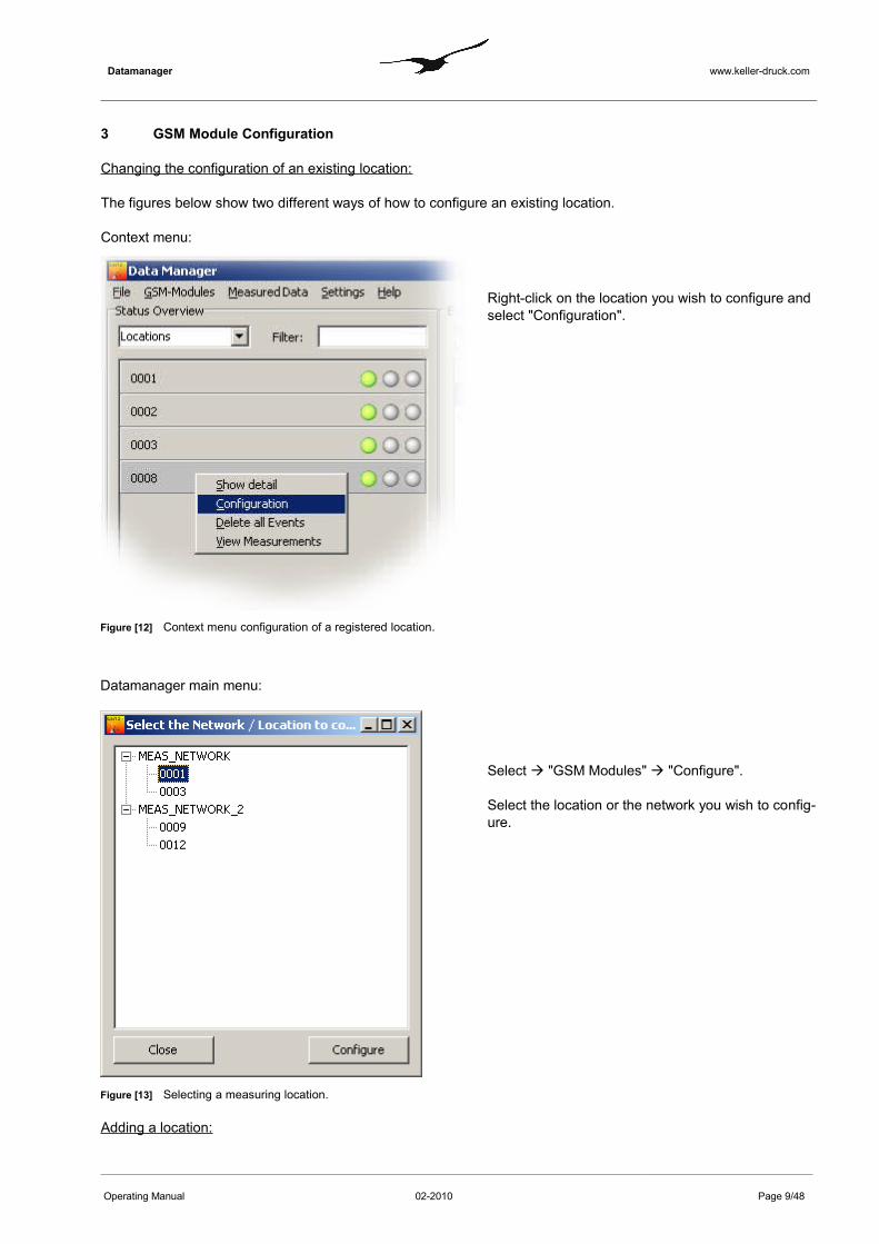
Changing the configuration of an existing location:
The figures below show two different ways of how to configure an existing location.
Context menu:
Figure [12] Context menu configuration of a registered location.
Datamanager main menu:
Right-click on the location you wish to configure and select "Configuration".
Figure [13] Selecting a measuring location.
Select "GSM Modules" "Configure".
Select the location or the network you wish to config-ure.
Adding a location:
Operating Manual 02-2010 Page 9/48

Datamanager www.keller-druck.com
To add a location, select "GSM Modules" "New" " "Location":
Figure [14] Main menu for manually adding a new measuring location
When a location is selected, the dialog shown in 3 allows you to examine and configure all the parameters that be-long to the location in question.
Figure [15] "Configure location" dialog
Operating Manual 02-2010 Page 10/48

Datamanager www.keller-druck.com
The configuration process is divided into two sections:
Tabs with the symbol show the configuration of the GSM module. Changes executed here will send a configuration command (email) to the corresponding GSM module.
GeneralNetwork, name, phone number, description (coordinates of the location).
ChannelsConfiguration of the GSM type, enable/disable channels, calibration of each channel.
CommunicationGPRS settings, email settings, SMS settings.
MessagesConfiguration of the different message types.
These configurations correspond with the program GSM Setup. Read the GSM Setup manual for further information.
The following functions are for data processing and not for GSM-2 module configuration:
CalculationsConfiguration of different calculations, i.e. water level etc.
ForwardingEvents like incoming emails can be forwarded to any recipient.
Data RequestRequests data from a GSM module.
3.1 Status Symbols
The GSM-2 modules can be configured remotely with the Datamanager if the firmware version of the GSM module is at least 07.18. If you have version 07.18 or higher, any configuration changes will trigger the procedure of sending a special con-figuration change email to the corresponding GSM-2 module.
Note that if the version is lower than 07.18, any configuration changes will only take place within the Datamanager and the following window will be displayed.
Figure [16] Configuration change information dialog .
Operating Manual 02-2010 Page 11/48
Datamanager www.keller-druck.com
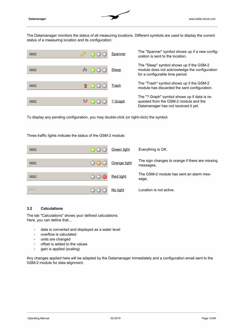
The Datamanager monitors the status of all measuring locations. Different symbols are used to display the current status of a measuring location and its configuration:
Spanner The "Spanner" symbol shows up if a new config-uration is sent to the location.
SleepThe "Sleep" symbol shows up if the GSM-2 module does not acknowledge the configuration for a configurable time period.
Trash The "Trash" symbol shows up if the GSM-2 module has discarded the sent configuration.
? GraphThe "? Graph" symbol shows up if data is re-quested from the GSM-2 module and the Datamanager has not received it yet.
To display any pending configuration, you may double-click (or right-click) the symbol.
Three traffic lights indicate the status of the GSM-2 module:
Green light Everything is OK.
Orange light The sign changes to orange if there are missing messages.
Red light The GSM-2 module has sent an alarm mes-sage.
No light Location is not active.
3.2 Calculations
The tab "Calculations" shows your defined calculations.Here, you can define that…
- data is converted and displayed as a water level- overflow is calculated- units are changed- offset is added to the values- gain is applied (scaling)
Any changes applied here will be adapted by the Datamanager immediately and a configuration email sent to the GSM-2 module for data alignment.
Operating Manual 02-2010 Page 12/48

Datamanager www.keller-druck.com
Following an example of adding a water level calculation:
Figure [17] Adding a calculation
Activate the "Calculation" tab and then press the button "Add".
Figure [18] Configuring a calculation
Number Description1 "Identifier"
"Scaling Gain/Offset""Unit of the Result"
You can assign any name to the new calculation.The default values are Gain=1 and Offset=0The calculation result has a physical unit
Note : You can use the Gain and Offset parameter to obtain the physical unit which ful-fils your requirements. The scaling is performed on the calculated value. The Datamanager always uses ISO standard units: Length is measured in m and pressure is measured in bar.The Datamanager carries out the calculation based on the raw data measured in
Operating Manual 02-2010 Page 13/48
12
3
4
5

Datamanager www.keller-druck.com
ISO physical units. A scaling on each calculated value can be executed.For example, you would like that calculations yield results measured in mm-wa-ter column the appropriate Gain would be 1000 because 1 m is equal to 1000 mm.
2
"Conversion to" You may choose one of the available conversions from the combobox. These are:
• Height of Water "e"• Depth to Water "f"• Height of Water above Sea Level "A"• Overflow (Poleni)• Overflow (Thomson)• Flow (Venturi)• Scaling
Note: Choose "Scaling" if you wish to apply the scaling with "Gain" and "Offset" only to the raw data. This might be the case if the measuring channel provides a physical value not representing a pressure, e.g. a voltage from a measuring gauge connected to the voltage input of the GSM-2 module.
3
"Channel Properties" For water level calculations you will need a pressure difference. The pressure difference between water pressure and ambient pressure eliminates the influ-ence of atmospheric variations due to weather changes. The default setting for calculating the relative water pressure is "P1-AP" so the pressure difference arises from the measurement of pressure gauge 1 in the water minus the value measured by the on-board barometer in the GSM-2 module.
Please note that this setting depends on the actual hardware connected to the GSM-2 module! If a relative pressure transmitter is connected the correct setting would be P1 only, because the relative pressure transmitter measures the pres-sure difference between water pressure and ambient pressure.
The Datamanager allows you to calculate the pressure difference based on measuring values from two different locations. This can be helpful if there are absolute pressure transmitters connected to the GSM-2 module and the baro-metric pressure should be obtained from a different location. Enabling the check-box "Value 2" activates the comboboxes "Network", "Location" and "Channel" which allow you to choose the second measuring location. In such configura-tions the radio group "Trigger-Channel" can be active for either "Value 1" or "Value 2". The setting of the "Trigger-Channel" determines which measuring value initiates the calculation of pressure differences. Please bear in mind that "Value1" and "Value2" do not necessarily arrive simultaneously at the Dataman-ager. There is a time tolerance which can be adjusted to ensure that only reas-onable pressure differences will be calculated. It is not expedient to calculate a pressure difference based on values measured on different days, for instance. In Chapter 5 5.1 you will find further explanations concerning the adjustment of the "Time band for calculations"
4 "Water Level Config-uration"
For reference only; all relevant parameters concerning the water level configura-tion are displayed in this group box.
5 "Overflow" The important parameters for overflow calculation according the formulas of Poleni or Thomson are shown in the group box "Overflow".
Operating Manual 02-2010 Page 14/48

Datamanager www.keller-druck.com
3.3 Remote Configuration of Water Level, Overflow and Calculation
The initial configuration of the GSM-2 modules is carried out on-site during installation with the help of the pro-gramming software "GSM Configuration". All parameters required for carrying out water level or overflow calcula-tions can be adjusted during start-up in the field, where the operator has the opportunity to validate the settings in the software via manual measurements to achieve reliable operation and monitoring of the measuring location.All settings can be sent by a configuration email to the Datamanager which then processes the email content. The Datamanager registers new measuring locations or updates the parameterization of an existing, previously re -gistered measuring location. The settings for water level calculations represent a part of such a parameterization and the Datamanager automatically adds a calculation as if the calculation had been added manually, as specified above in Section 3.2.
3.4 Water Level Configuration
The Datamanager offers access to all installation parameters and settings of any registered measuring location as shown in 3.4.
Figure [19] Water level configuration
Operating Manual 02-2010 Page 15/48
1
2
3

Datamanager www.keller-druck.com
Number Description
1
"Height above Sea Level"
"Installation Length"
"Water Density"
Altitude information is required if you wish to relate the calculated water level to the sea level (see 3.2 – "Conversion to)."Installation Length" is the total length of the system measured from the reference line of the sensor up to the reference plane on which the wa-ter levels should be correlated.Information about the density is required to derive level heights from pressure. 998.2 kg/m3 is the density of water at normal condition (20° C and pressure of 1 bar). Note that sea water has a higher density.
2
"Valid from" Datamanager maintains the chronology of the water level configuration. That means that the settings are linked to the date and time of validity. This is important whenever the settings are changed over the duration of monitoring the measuring location. Otherwise, water level calculations would lead to wrong results if measurement values from the past are combined with a parameterization which was not yet valid at that time!
It is highly recommendable to add a new water level parameterization with a new date and time of validity whenever adjustments of e.g. "In-stallation Length" are required! In the combobox marked with 3 select the item "new" to assign a new set of water level parameters with its date and time of validity.
3"New" Configuration There can be several sets of water level parameterizations with the date
and time of validity assigned to one measuring location. Please read the description "Valid from” for a better understanding.
3.5 (Over)Flow Configuration
The Datamanager supports three different types of calculations for flow and overflow respectively. Overflow calcu-lations based on the formulas of Poleni or Thomson and flow can be measured with a Venturi tube. Applying the Poleni or Thomson formula depends on the layout of the monitored spillway.
Figure [20] Flow and overflow calculations according to Poleni or Thomson.
Number Description
Operating Manual 02-2010 Page 16/48
1
2
3
4

Datamanager www.keller-druck.com
1 "Poleni / Venturi" Specify the width measured in m and the appropriate form type
2 "Thomson" Enter the angle measured in degrees (°) of the Thomson spillway or V-Notch weir
3 "General" Specify the form factor
4
"Overflow" For reliable measurements a minimum calculation height has to be specified. The minimum calculation height represents the threshold when the water flow over the weir complies with well-defined hydraulic conditions and Poleni’s formula yields reasonable results.Only heights equal to or greater than the minimum calculation height will be taken into consideration for flow level calculations.
3.6 Message Forwarding
Information or alarm notification messages are bound to a location and can be forwarded to any email address or phone number.
Figure [21] Message forwarding as a part of a location’s configuration
Press "Add" to specify a new message forwarding rule or "Edit" to view or modify an existing forwarding rule. The dialog window as shown in 3.6 will be displayed.
Figure [22] Definition of a message forwarding rule
Operating Manual 02-2010 Page 17/48
1
23
4
5 6
7
Datamanager www.keller-druck.com
Number Description
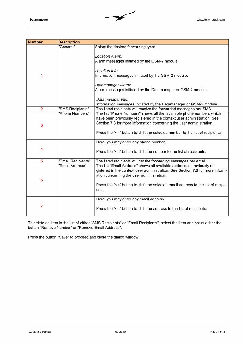
1
"General" Select the desired forwarding type:
Location Alarm: Alarm messages initiated by the GSM-2 module.
Location Info: Information messages initiated by the GSM-2 module.
Datamanager Alarm: Alarm messages initiated by the Datamanager or GSM-2 module.
Datamanager Info:Information messages initiated by the Datamanager or GSM-2 module.
2 "SMS Recipients" The listed recipients will receive the forwarded messages per SMS
3
"Phone Numbers" The list "Phone Numbers" shows all the available phone numbers which have been previously registered in the context user administration. See Section 7.8 for more information concerning the user administration.
Press the "<<" button to shift the selected number to the list of recipients.
4
Here, you may enter any phone number.
Press the "<<" button to shift the number to the list of recipients.
5 "Email Recipients" The listed recipients will get the forwarding messages per email.
6
"Email Address" The list "Email Address" shows all available addresses previously re-gistered in the context user administration. See Section 7.8 for more inform-ation concerning the user administration.
Press the "<<" button to shift the selected email address to the list of recipi-ents.
7
Here, you may enter any email address.
Press the "<<" button to shift the address to the list of recipients.
To delete an item in the list of either "SMS Recipients" or "Email Recipients", select the item and press either the button "Remove Number" or "Remove Email Address".
Press the button "Save" to proceed and close the dialog window.
Operating Manual 02-2010 Page 18/48

Datamanager www.keller-druck.com
3.7 Data Request
GSM-2 modules driven with a firmware version higher than or equal to 09.09 are able to record measured data like a data logger. Datamanager allows you to request the recorded data from such GSM-2 modules. The Datamanager application generates a data request email and sends it to the GSM-2 module in question asking for measured data within a specified time period.
Figure [23] Data Request functionality of the Datamanager
Specify the desired period with the help of the date and time input fields "From" and "To" and then press the button "Send Request".
Note: The GSM-2 module can send a maximum of 10 emails (approx. 2000 items of measured data). If you need more data, initiate an additional data request once you have received the data of the previous one.
Operating Manual 02-2010 Page 19/48

Datamanager www.keller-druck.com
4 Email Configuration
The following procedure describes how an email account is created in order to receive data sent by the GSM-2 module. In the Datamanager main menu, select "Settings" and then "General" to call up the dialog window shown in 4.
Enable the option "Use Email" and press "OK"
Figure [24] General settings -> Communication
Select "Settings" and then "Email" in the Datamanager's main menu to call up the configuration dialogs of an email account.
Figure [25] Email administration.
Press the button "Add" to create a new email account or "Edit" to view and modify a previously created account.
Operating Manual 02-2010 Page 20/48
Datamanager www.keller-druck.com
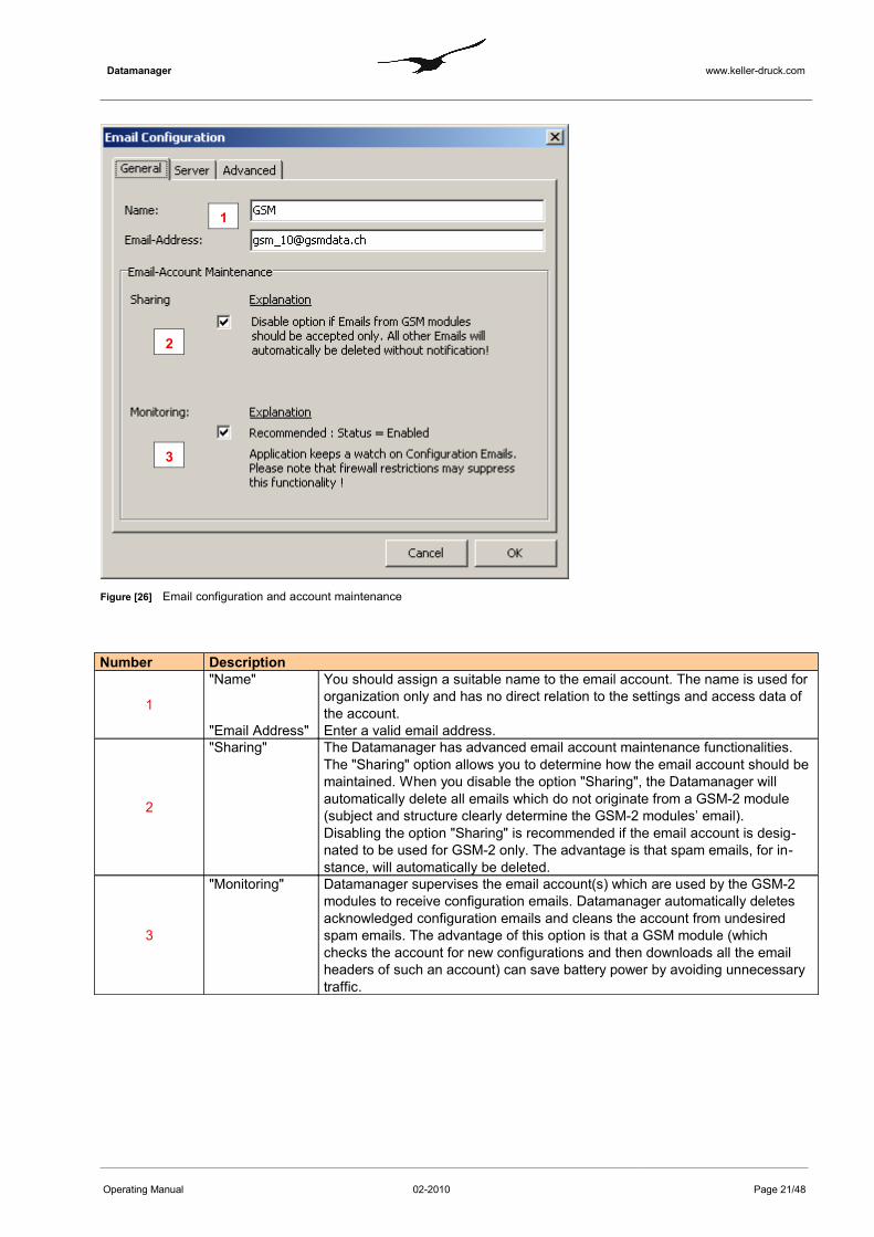
Figure [26] Email configuration and account maintenance
Number Description
1
"Name"
"Email Address"
You should assign a suitable name to the email account. The name is used for organization only and has no direct relation to the settings and access data of the account.Enter a valid email address.
2
"Sharing" The Datamanager has advanced email account maintenance functionalities. The "Sharing" option allows you to determine how the email account should be maintained. When you disable the option "Sharing", the Datamanager will automatically delete all emails which do not originate from a GSM-2 module (subject and structure clearly determine the GSM-2 modules’ email).Disabling the option "Sharing" is recommended if the email account is desig-nated to be used for GSM-2 only. The advantage is that spam emails, for in-stance, will automatically be deleted.
3
"Monitoring" Datamanager supervises the email account(s) which are used by the GSM-2 modules to receive configuration emails. Datamanager automatically deletes acknowledged configuration emails and cleans the account from undesired spam emails. The advantage of this option is that a GSM module (which checks the account for new configurations and then downloads all the email headers of such an account) can save battery power by avoiding unnecessary traffic.
Operating Manual 02-2010 Page 21/48
1
2
3
Datamanager www.keller-druck.com
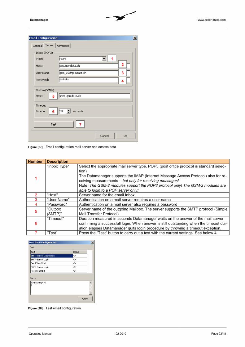
Figure [27] Email configuration mail server and access data
Number Description
1
"Inbox Type" Select the appropriate mail server type. POP3 (post office protocol is standard selec-tion) The Datamanager supports the IMAP (Internet Message Access Protocol) also for re-ceiving measurements – but only for receiving messages!Note: The GSM-2 modules support the POP3 protocol only! The GSM-2 modules are able to login to a POP server only!
2 "Host" Server name for the email Inbox3 "User Name" Authentication on a mail server requires a user name4 "Password" Authentication on a mail server also requires a password
5 "Outbox (SMTP)"
Server name of the outgoing Mailbox. The server supports the SMTP protocol (Simple Mail Transfer Protocol)
6"Timeout" Duration measured in seconds Datamanager waits on the answer of the mail server
confirming a successfull login. When answer is still outstanding when the timeout dur-ation elapses Datamanager quits login procedure by throwing a timeout exception.
7 "Test" Press the "Test" button to carry out a test with the current settings. See below 4
Figure [28] Test email configuration
Operating Manual 02-2010 Page 22/48
12
3
4
5
6
7
Datamanager www.keller-druck.com
5 Additional Settings
5.1 General Configuration
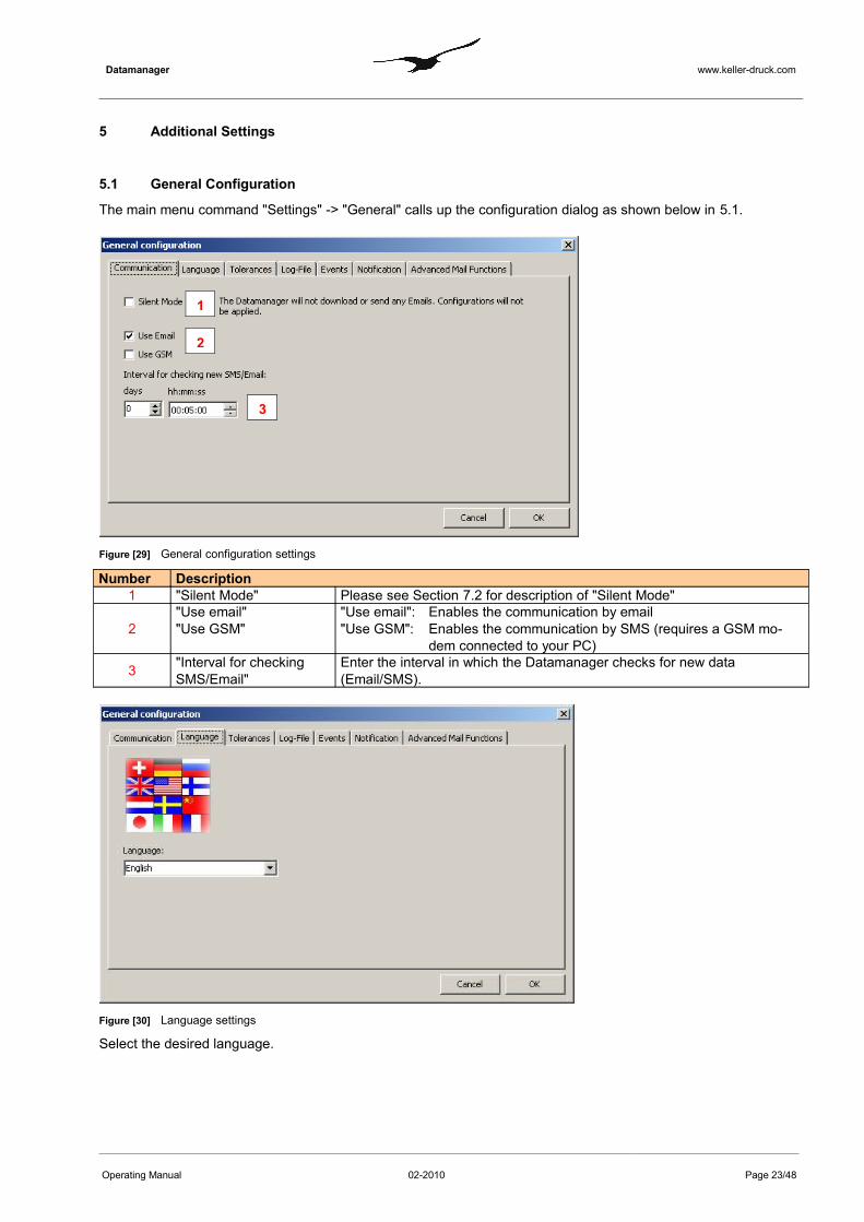
The main menu command "Settings" -> "General" calls up the configuration dialog as shown below in 5.1.
Figure [29] General configuration settings
Number Description1 "Silent Mode" Please see Section 7.2 for description of "Silent Mode"
2"Use email" "Use GSM"
"Use email": Enables the communication by email"Use GSM": Enables the communication by SMS (requires a GSM mo-
dem connected to your PC)
3 "Interval for checking SMS/Email"
Enter the interval in which the Datamanager checks for new data (Email/SMS).
Figure [30] Language settings
Select the desired language.
Operating Manual 02-2010 Page 23/48
1
2
3

Datamanager www.keller-druck.com
Figure [31] Time tolerance settings
Number Description
1
"Time tolerance for missing mes-sages"
The "Time tolerance for missing messages" defines how long the Datamanager waits for expected data from the locations. If no data is received within the specified time, Datamanager creates an info event which informs the user that data is over-due.
2
"Time band for calculations"
The "Time band for calculations" defines the maximum time difference between two measurements, i.e. P1 (level sensor) & AP (air pressure) so that a calculation can be executed (this is only relevant if the data comes from two different locations).Also see Section 3.2 Calculations "Channel Properties
Figure [32] Log file settings
The Datamanager creates a continuous log file when active. In the tab "Log-File" you can define three different levels:Normal: Only important messages are registered. Error: The log file states which errors occurred (in addition to the "Normal"-messages)Debug: All possible messages are written into the log file (note that this creates a large log file size).
"Error" setting is recommended.
Operating Manual 02-2010 Page 24/48

Datamanager www.keller-druck.com
Figure [33] Setting events and how they are displayed
In the tab "Events" you can define for each incoming message (email or SMS) which event type should be dis-played:OK: Leaves the traffic light on green.Info: Turns the traffic light to orange.
Events DescriptionNew Data New data (Email/SMS) processed.New Configuration New email with configuration arrived.Configuration (no changes) An email with an already known configuration arrived.Measuring Value invalid The measuring data is not within the specified range.
Figure [34] Setting notification by email or SMS
The Datamanager allows you to send a notification to any email address or phone number whenever a registration email is received by the Datamanager. Enable the appropriate checkbox and enter a valid recipient.Note: Sending SMS requires a GSM modem connected to your PC!
Operating Manual 02-2010 Page 25/48

Datamanager www.keller-druck.com
6 Export Data
Figure [35] Export Scheduler for exporting data for other applications
The Datamanager offers several export filters to make the measurements or calculated values available to other applications. The application maintains a list of independent data export rules or tasks. In the Datamanager main menu, choose the commands "Measured Data" "Export Scheduler" to call up the list as shown above in 6 . Each item in the list of the Export Scheduler consists of a customizable name, the indicator which export filter should be applied, the date and time when the scheduler will carry out the data export, the time interval of recurrent data export and, finally, the path where the data should be stored.
Export Filter DescriptionCSV The CSV export filter generates a text-based output file where the data is arranged in
a vector. If more than one measuring channel was selected for data export, the chan-nel data is grouped in sections which follow one another.CSV = Comma-Separated Values
CSV-2 The CSV-2 export filter also generates a text file. In contrast to the CSV filter expor-ted data will be arranged in a matrix, where each column represents data from a measuring channel.
Delft FEWS The Delft FEWS export filter generates an XML file according to the Delft FEWS pub-lished interface. The exported data is treated as Time Series and satisfies the Delft FEWS XML Schema and Namespaces.
HYDRAS The HYDRAS export filter generates text-based files which are suitable for the auto-import functionalities of Hydras. The files contain an XML-like header describing the measuring location and channel as follows:<STATION>0000000706</STATION><SENSOR>0010</SENSOR>The data is structured in tabulator-separated columns:Date TAB Time TAB Value
Overflow The Datamanager is able to calculate an "Overflow Report" based on the settings de-scribed in Section 3.5
External Application The Datamanager can launch any external software or batch file script in connection with CMD.exe. In this context KELLER offers an FTP uploader program which allows you to upload exported data files on any FTP server.
Follow the steps described below to add and configure a new data export task in the Export Scheduler's list..
Operating Manual 02-2010 Page 26/48

Datamanager www.keller-druck.com
Figure [36] Configuring a data export rule: export format and export category
Number Description
1 "Export to" Select the appropriate export format. The description of available export formats can be found in the table above; see Export Filter
2
"Single Export" Two categories of data export are available."Single Export" and "Recurrent Export", whereby the single export is carried out only once and the recurrent export will become an Export Scheduler list item and will be performed periodically.Note: the option must be disabled to create a recurrent export rule.
3 "Name" Any name can be assigned to a recurrent data export for easier distinction.
4
"Data" Select which data should be taken into consideration for data export."New Data" means that only new measurements (since the last recurrent export has been carried out) will be shown in the data export file."All Data" forces the Datamanager to export all available data from a measuring location.
Operating Manual 02-2010 Page 27/48
1
2
3
4
Datamanager www.keller-druck.com
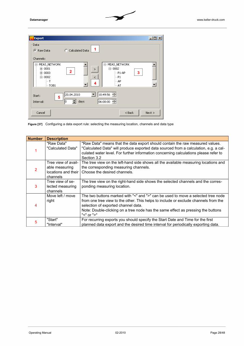
Figure [37] Configuring a data export rule: selecting the measuring location, channels and data type
Number Description
1
"Raw Data" "Calculated Data"
"Raw Data" means that the data export should contain the raw measured values."Calculated Data" will produce exported data sourced from a calculation, e.g. a cal-culated water level. For further information concerning calculations please refer to Section 3.2
2
Tree view of avail-able measuring locations and their channels
The tree view on the left-hand side shows all the available measuring locations and the corresponding measuring channels. Choose the desired channels.
3Tree view of se-lected measuring channels
The tree view on the right-hand side shows the selected channels and the corres-ponding measuring location.
4
Move left / move right
The two buttons marked with "<" and ">" can be used to move a selected tree node from one tree view to the other. This helps to include or exclude channels from the selection of exported channel data.Note: Double-clicking on a tree node has the same effect as pressing the buttons "<" or ">"
5 "Start""Interval"
For recurring exports you should specify the Start Date and Time for the first planned data export and the desired time interval for periodically exporting data.
Operating Manual 02-2010 Page 28/48
1
2 3
4
5

Datamanager www.keller-druck.com
Figure [38] Configuring a data export rule: definition of filename and export path
Number Description1 "Path" Press the button "Select" to browse for a valid export path
2
"FileName" The filename can be customized with the help of the listed variables marked with #. You may combine these variables together with any characters between the #variables# . In the Field "Example" you can see what the result-ing file name will look like.
Operating Manual 02-2010 Page 29/48
1
2
Datamanager www.keller-druck.com
7 Features of the Datamanager
7.1 Import Measurements from IDC/DX5-Files
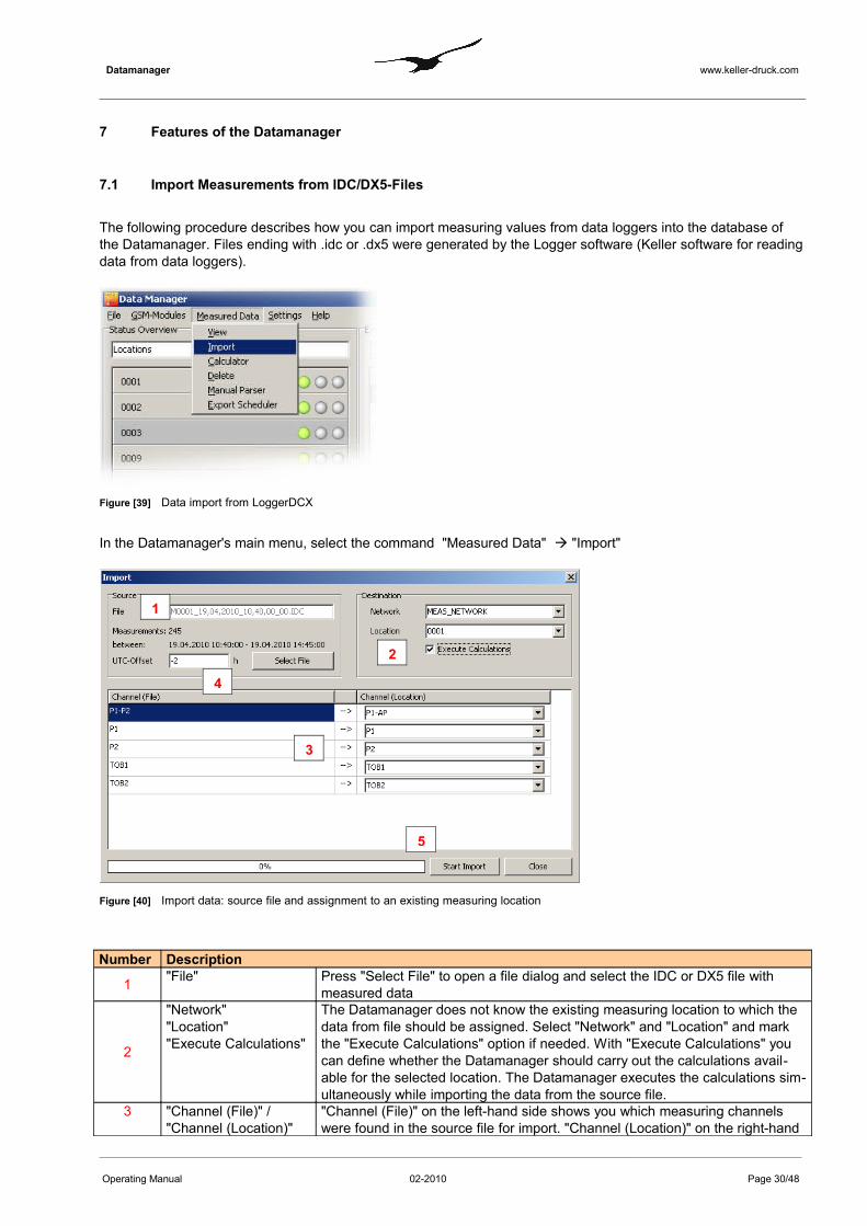
The following procedure describes how you can import measuring values from data loggers into the database of the Datamanager. Files ending with .idc or .dx5 were generated by the Logger software (Keller software for reading data from data loggers).
Figure [39] Data import from LoggerDCX
In the Datamanager's main menu, select the command "Measured Data" "Import"
Figure [40] Import data: source file and assignment to an existing measuring location
Number Description
1 "File" Press "Select File" to open a file dialog and select the IDC or DX5 file with measured data
2
"Network""Location""Execute Calculations"
The Datamanager does not know the existing measuring location to which the data from file should be assigned. Select "Network" and "Location" and mark the "Execute Calculations" option if needed. With "Execute Calculations" you can define whether the Datamanager should carry out the calculations avail-able for the selected location. The Datamanager executes the calculations sim-ultaneously while importing the data from the source file.
3 "Channel (File)" / "Channel (Location)"
"Channel (File)" on the left-hand side shows you which measuring channels were found in the source file for import. "Channel (Location)" on the right-hand
Operating Manual 02-2010 Page 30/48
1
2
3
4
5
Datamanager www.keller-druck.com
side shows all the available channels of the selected measuring location. Map channels as required.
4
“UTC-Offset” Important ! Please note that Datamanager treats internally all timestamps in UTC (Universal Time Coordinated formerly Greenwich Mean Time GMT) but dis-plays them adjusted to the local time according to the time zone settings of your PC. Data which originates from LoggerDCX does not contain information about UTC Offset that’s why the appropriate UTC Offset has to be adjusted manually in order to define in which time zone the LoggerDCX has been col-lecting data.
5 "Start Import" Proceed with "Start Import".
7.2 Silent Mode
The Datamanager can be set to silent mode. In this mode, no emails or SMS are sent or received and the data in the database remains unchanged.
However, silent mode does allow you to display existing data and configurations and to carry out data exports.
To enable silent mode, select "Settings" "General" and activate the checkbox on the first tab named "Silent Mode".
7.3 Calculator
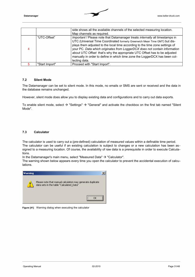
The calculator is used to carry out a (pre-defined) calculation of measured values within a definable time period. The calculator can be useful if an existing calculation is subject to changes or a new calculation has been as -signed to a measuring location. Of course, the availability of raw data is a prerequisite in order to execute Calcula-tions.In the Datamanager's main menu, select "Measured Data" "Calculator". The warning shown below appears every time you open the calculator to prevent the accidental execution of calcu-lations.
Figure [41] Warning dialog when executing the calculator
Operating Manual 02-2010 Page 31/48

Datamanager www.keller-druck.com
Figure [42] Calculator
Number Description
1
"Network""Location""Calculation"
You need to specify from which Network and Location the raw measure-ment data should be selected to perform the calculation(s)The combobox shows all calculations belonging to the selected Location. Each calculation is represented by its name.See "Identifier” in Section 3.2 for further information concerning calculations and their definition.
2 "From" / "To" Specify the desired time period.3 "Calculate" Proceed with "Calculate".
7.4 Manual Parser
If an error message has been created by the Datamanager, the manual parser is used to analyse the incoming data and to split the measurements into individual channels. This allows measured values to be assigned manually to the corresponding location.
Figure [43] Info message: handling with manual parser
A right-click on the "Message" allows you to start the manual parser.
Operating Manual 02-2010 Page 32/48
1 2
3

Datamanager www.keller-druck.com
Figure [44] Manual parser
Under "Network" and "Location", select the appropriate measuring location to which the content of the "Message" belongs.Paste the "Message" as shown in 7.4 in the Textbox named "Content".Specify the time of the first measurement and the interval between measurements.In the table "Mapping" on the right-hand side you should check the time-stamp of each measurement and assign it to a channel.Click "Suggest Channels" to automatically assign the values to the measuring channels.
7.5 Manual Data Maintenance - Deleting Data Sets
Any data in the Datamanager's underlying database can be deleted by hand. In the Datamanager main menu, se-lect the commands "Measured Data" "Delete" to call up the dialog window shown below in 7.5.
Figure [45] Manual data maintenance - deleting data sets
The Datamanager offers several methods of deleting data sets in the database. The table below shows a list of the different methods.
Operating Manual 02-2010 Page 33/48
Datamanager www.keller-druck.com
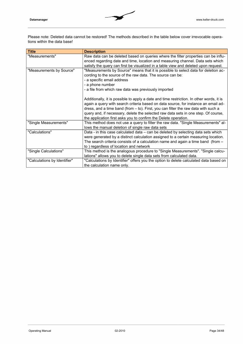
Please note: Deleted data cannot be restored! The methods described in the table below cover irrevocable opera-tions within the data base!
Title Description"Measurements" Raw data can be deleted based on queries where the filter properties can be influ-
enced regarding date and time, location and measuring channel. Data sets which satisfy the query can first be visualized in a table view and deleted upon request.
"Measurements by Source" "Measurements by Source" means that it is possible to select data for deletion ac-cording to the source of the raw data. The source can be:- a specific email address - a phone number- a file from which raw data was previously imported
Additionally, it is possible to apply a date and time restriction. In other words, it is again a query with search criteria based on data source, for instance an email ad-dress, and a time band (from – to). First, you can filter the raw data with such a query and, if necessary, delete the selected raw data sets in one step. Of course, the application first asks you to confirm the Delete operation.
"Single Measurements" This method does not use a query to filter the raw data. "Single Measurements" al-lows the manual deletion of single raw data sets
"Calculations" Data - in this case calculated data – can be deleted by selecting data sets which were generated by a distinct calculation assigned to a certain measuring location.The search criteria consists of a calculation name and again a time band (from – to ) regardless of location and network
"Single Calculations" This method is the analogous procedure to "Single Measurements". "Single calcu-lations" allows you to delete single data sets from calculated data.
"Calculations by Identifier" "Calculations by Identifier" offers you the option to delete calculated data based on the calculation name only.
Operating Manual 02-2010 Page 34/48

Datamanager www.keller-druck.com
7.6 Delete Locations
For administration purpose it is necessary to have functions that help maintain the measurement network. The first function which should now be discussed is how to delete a location.The Datamanager does not delete the information relating to a location and all corresponding raw data and calcu-lated data in one step. First, the information will only be marked as deleted - the data still remains in the database. The Datamanager simply hides all information from a deleted location. If necessary, a deleted location can be re-stored at a later date. Restoring a deleted location is described in Section7.7.
Figure [46] Deleting an existing location
To call up the dialog box shown in 7.6 above, select the command "GSM modules" "Configure from the Datamanager's main menu. Select the location you wish to delete. In the tab "General", click on the "Delete Location" button to delete the se-lected location.
Note:If a location is deleted, a copy of the phone number is written into the description text corresponding to the location.
The location becomes inactive and is hidden. The phone number, which has the function of a unique identifier of any location, is now free to be used by a new location.
Operating Manual 02-2010 Page 35/48
Datamanager www.keller-druck.com
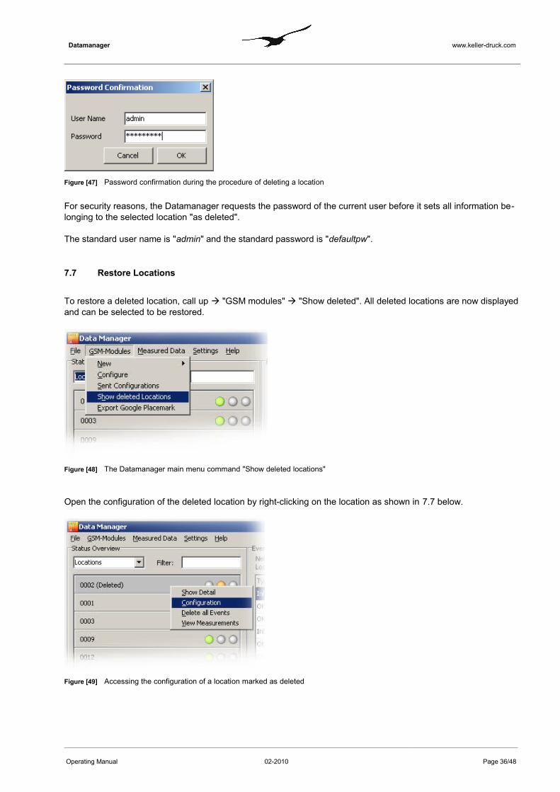
Figure [47] Password confirmation during the procedure of deleting a location
For security reasons, the Datamanager requests the password of the current user before it sets all information be-longing to the selected location "as deleted".
The standard user name is "admin" and the standard password is "defaultpw".
7.7 Restore Locations
To restore a deleted location, call up "GSM modules" "Show deleted". All deleted locations are now displayed and can be selected to be restored.
Figure [48] The Datamanager main menu command "Show deleted locations"
Open the configuration of the deleted location by right-clicking on the location as shown in 7.7 below.
Figure [49] Accessing the configuration of a location marked as deleted
Operating Manual 02-2010 Page 36/48

Datamanager www.keller-druck.com
Figure [50] Restore or irrevocably delete a location
Number Description
1
"Restore Location" Reactivates the location Attention: You have to enter a valid phone number in the field "Phone Num-
ber"! Valid means that this phonenumber is not yet occupied by another measuring location.
2 "Irrevocably Delete Loca-tion"
Attention: All data in the data base will be deleted. All information belonging to the selected location will be lost!
Operating Manual 02-2010 Page 37/48
2 1

Datamanager www.keller-druck.com
7.8 User Administration
Selecting "Settings" "User" opens the user administration form. Here, you can define different users and their privileges. Check the option "Enable User Administration" if you want to enable "User Administration" the dialog box.
Figure [51] User administration
Number Description1 "Select User" Tree view showing all registered users
2 "Create new User"
Press the button "Create new User" to add a data set to store the user data.
3
"User Group" From the "User Group" combobox, select either "Admin" or "User" as required.All members from the group "User" have restricted access privileges. They are only allowed to view data but not to manipulate or delete any data. Members of the group "Admin" have full access. Only these users can delete data or change configurations.
4 Personal data of the user plus login information for authentication.
5 "Add" You can add any number of different email addresses to a user. Press "add" to fill the list with valid email addresses.
6 "Delete" Select any email address in the list and then "delete" to remove the address from the list.
7 "Add" You can add one or several phone numbers to a user account. Press the "add" button to add the phone number visible in the edit field "Phone No" to the list.
8 "Delete" Removes a selected phone number from the list.9 "Add" Adds the information belonging to the user and stores it in the data base
7.9 Login
Operating Manual 02-2010 Page 38/48
1
2
3
4
5
6
7
8
9
Datamanager www.keller-druck.com
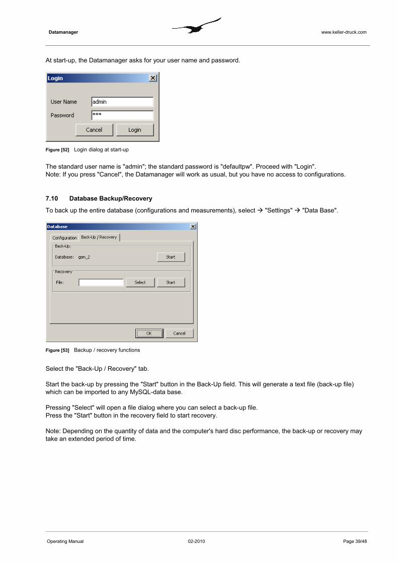
At start-up, the Datamanager asks for your user name and password.
Figure [52] Login dialog at start-up
The standard user name is "admin"; the standard password is "defaultpw". Proceed with "Login".Note: If you press "Cancel", the Datamanager will work as usual, but you have no access to configurations.
7.10 Database Backup/Recovery
To back up the entire database (configurations and measurements), select "Settings" "Data Base".
Figure [53] Backup / recovery functions
Select the "Back-Up / Recovery" tab.
Start the back-up by pressing the "Start" button in the Back-Up field. This will generate a text file (back-up file) which can be imported to any MySQL-data base.
Pressing "Select" will open a file dialog where you can select a back-up file. Press the "Start" button in the recovery field to start recovery.
Note: Depending on the quantity of data and the computer's hard disc performance, the back-up or recovery may take an extended period of time.
Operating Manual 02-2010 Page 39/48

Datamanager www.keller-druck.com
8 GSM Terminal Configuration
The Datamanager allows you to use a GSM terminal for sending and receiving SMS. The GSM terminal needs to be connected to a serial port of the computer on which the Datamanager is installed. For reliable operation it is re-commendable to use a GSM terminal for industrial applications and environments.
The main menu command "Settings" "GSM Terminal" calls up the dialog window as shown below.
Figure [54] GSM terminal configuration
Operating Manual 02-2010 Page 40/48

Datamanager www.keller-druck.com
Figure [55] Serial communication with connected GSM terminal
The figure above shows the configuration dialog during serial port scanning. The settings in the edit fields "From" and "To" allow you to specify the port numbers that should be checked if a connected GSM terminal can be detected. This is helpful when you already know the port number on which the GSM terminal was connected."Allow all Ports" enables you to scan all of the computer's serial ports.
The example above shows the successful recognition of a GSM terminal on port number 7. When it scans serial ports the Datamanager tries to send specific "AT" commands to the connected hardware. Whenever a device an-swers with "AT OK" the Datamanager assumes that the connected device is a GSM Terminal.
Figure [56] Configuration of a GSM terminal
Operating Manual 02-2010 Page 41/48
1
2
3
4
5
6
7
8
9

Datamanager www.keller-druck.com
Number Description
1
"Com Ports""Open / "Close"
If the Datamanager successfully recognizes a GSM terminal it automatically se-lects the corresponding port number in the combobox.The "Open/Close" button changes its caption according to the state of the serial port. Press "Open" to activate the COM port for communication.
2
"Init Device" Press "Init Device" to initialize the connected hardware. The Datamanager sends a set of specific commands to the device to establish proper communication and to wake up the hardware.In the text box marked with the number 8 you can see the test results of the dif-ferent procedures executed by pressing the buttons.
3
"PDU / Text Mode" Press "Detect SMS Mode" to check which operation mode is supported by the connected hardware. There are two different operation modes possible: PDU and/or text mode."Detect current Mode" shows which mode is currently active."Set Mode" will send the appropriate command to the hardware to set the opera-tion mode according to the selected check box "PDU" or "TTEXT"
4"Available Memory" You can detect which types of memory are available. For descriptions of what
"ME" "MT" and "SM" stand for, please refer to the information provided by the manufacturer of the connected hardware.
5
"Detect current Memory"" Set Memory"
This function allows you to detect which memory usage settings are currently active in the hardware.Use "Set Memory" to assign memory settings according to the selections of the checkboxes "ME1" to "ME3"
6
"Detect Routing""Set Routing"
Detect Routing checks the currently active routing settings of the connected hardware."Set Routing" writes the selection of the radio group selectors to the hardware.The routing supported depends on the hardware. Please refer to the manufac-turer's manuals and descriptions.
7"Signal Quality" Press the button "Signal Quality" to check the field strength. Poor signal quality
may disturb the transmission of an SMS. For reliable operation it is necessary to have the best possible signal quality.
8 "Text Box" This text box lists all of the test results. The example shows the results after suc-cessful completion of each test.
9"Save Settings""Close without sav-ing"
Close the configuration dialog by clicking on "Save Settings" if you wish to per-manently store the selected configuration."Close without saving" just closes the dialog but does not store the settings.
Operating Manual 02-2010 Page 42/48

Datamanager www.keller-druck.com
Figure [57] Configuration of a GSM terminal – diagnosis
Use the "Diagnose" tab to send single commands to the hardware for analysis and low level tests for trouble shoot-ing.The combobox contains a set of standard commands which you can choose for testing. Please note there are powerful commands which can have a far-reaching impact on the connected hardware and its behaviour.Please first refer to the manufacturer's manual and description before you send any of these commands to the hardware!
"Maximum number of errors accepted while reading SMS" Depending on the memory management of the connected hardware it is sometimes necessary to increase this number. SMS are usually stored in a stack in the memory of the hardware. Each place can be accessed by its number. When the Datamanager tries to read an SMS from a place number where no SMS is available the hard-ware can answer with an error. If this error counter is set to 10, as in the example, the Datamanager checks place numbers 1 to 10. If there are no SMS available, the Datamanager will stop the procedure. If a new SMS were at place number 12 it would not be recognized. Memory management is highly hardware-specific. In the event of problems with SMS reception, it may be necessary to carry out tests while adapting the error counter.
The "Delete Option" setting is also very specific to the connected hardware. It is not possible to describe here which setting should be applied for the hardware you intend to use. Please refer to the manufacturer's manual.
Operating Manual 02-2010 Page 43/48

Datamanager www.keller-druck.com
9 Differences between GSM-1 and GSM-2
Feature GSM-1 GSM-2
Communication By SMS only By SMS and email
Configuration Datamanager and GSM module must be con-figured separately.
No remote configuration supported.
Version 7.12:Same as GSM-1
Version ≥ 7.15:Remote registration supported (from GSM-2 to the Dataman-ager).
Version ≥ 7.18:Remote configurations supported (bi-directional)
Version ≥ 08.15Type 4 and 5 in "Hardware Settings Connected Device" (see Operating Manual GSM-2) supported.
Version ≥ 09.07Type 6 and 7 in "Hardware Settings Connected Device" (see Operating Manual GSM-2) supported.
Version ≥ 09.09Integrated record and event logging function.
Operating Manual 02-2010 Page 44/48

Datamanager www.keller-druck.com
10 Database
The Datamanager supports two types of database (must be set upon program start):- MySQL:
Requires an active MySQL database running on the same computer or on a remote server. - SQLite:
No additional configuration or installation required. The entire database consists of a single file.
10.1 Installing MySQL
The MySQL server can be installed on any PC with network access. To download the MySQL setup, go to http://dev.mysql.com/downloads/
Choose the latest version of the community server and download the "Windows Essentials (x86)" for a computer running Windows XP or Vista.
We recommend downloading the MySQL GUI Tools as well. The GUI Tools are very helpful for server administra -tion (e.g. for running back-ups, user and access privilege administration, troubleshooting and monitoring).
10.2 Installing the Database Server (Windows)
Run the MySQL setup file and follow the instructions. Always proceed with the "Next"-button without changing any values (default settings).
Note: be sure to remember the password given to the root user!
Choose "Configure MySQL-Server now" to carry out the initial configuration.
Operating Manual 02-2010 Page 45/48

Datamanager www.keller-druck.com
11 Index of Figures
Number Title Page
Figure [1]Environment of the GSM-2 Datamanager .................................................................................................. 4
Figure [2]Principle of data management .................................................................................................................... 4
Figure [3] First start database concept and language selection. ...................................................................................................................................................................... 5
Figure [4]Custom configuration of MySQL server access and test of the connection to the server. ................ 5
Figure [5]Testing the access to the MySQL server. ................................................................................................. 6
Figure [6]Specifying the MySQL database name. ........................................................................................................................................................................................ 6
Figure [7]Communication technology email and SMS. ............................................................................................ 6
Figure [8]Login at application start. ........................................................................................................................... 6
Figure [9]Email administration. .................................................................................................................................. 7
Figure [10]GSM terminal configuration. ..................................................................................................................... 7
Figure [11]Datamanager main window. ........................................................................................................................................................................................ 8
Figure [12]Context menu configuration of a registered location. ........................................................................... 9
Figure [13]Selecting a measuring location. ............................................................................................................... 9
Figure [14]Main menu for manually adding a new measuring location ............................................................... 10
Figure [15]"Configure location" dialog .................................................................................................................... 10
Figure [16]Configuration change information dialog . ........................................................................................... 11
Figure [17]Adding a calculation ...................................................................................................................................................................................... 13
Figure [18]Configuring a calculation
...................................................................................................................................................................................... 13
Figure [19]Water level configuration ........................................................................................................................ 15
Figure [20]Flow and overflow calculations according to Poleni or Thomson. ................................................... 16
Operating Manual 02-2010 Page 46/48

Datamanager www.keller-druck.com
Figure [21]Message forwarding as a part of a location’s configuration
...................................................................................................................................................................................... 17
Figure [22]Definition of a message forwarding rule ............................................................................................... 17
Figure [23]Data Request functionality of the Datamanager ................................................................................... 19
Figure [24]General settings -> Communication
...................................................................................................................................................................................... 20
Figure [25]Email administration. .............................................................................................................................. 20
Figure [26]Email configuration and account maintenance
...................................................................................................................................................................................... 21
Figure [27]Email configuration mail server and access data
...................................................................................................................................................................................... 22
Figure [28]Test email configuration ......................................................................................................................... 22
Figure [29]General configuration settings .............................................................................................................. 23
Figure [30]Language settings ................................................................................................................................... 23
Figure [31]Time tolerance settings ........................................................................................................................... 24
Figure [32]Log file settings ....................................................................................................................................... 24
Figure [33]Setting events and how they are displayed
...................................................................................................................................................................................... 25
Figure [34]Setting notification by email or SMS ...................................................................................................................................................................................... 25
Figure [35]Export Scheduler for exporting data for other applications
...................................................................................................................................................................................... 26
Figure [36]Configuring a data export rule: export format and export category .................................................. 27
Figure [37]Configuring a data export rule: selecting the measuring location, channels and data type
...................................................................................................................................................................................... 28
Operating Manual 02-2010 Page 47/48

Datamanager www.keller-druck.com
Figure [38]Configuring a data export rule: definition of filename and export path
...................................................................................................................................................................................... 29
Figure [39]Data import from LoggerDCX ................................................................................................................. 30
Figure [40]Import data: source file and assignment to an existing measuring location ................................... 30
Figure [41]Warning dialog when executing the calculator .................................................................................... 31
Figure [42]Calculator ...................................................................................................................................................................................... 32
Figure [43]Info message: handling with manual parser ........................................................................................ 32
Figure [44]Manual parser ......................................................................................................................................... 33
Figure [45]Manual data maintenance - deleting data sets ..................................................................................... 33
Figure [46]Deleting an existing location .................................................................................................................. 35
Figure [47]Password confirmation during the procedure of deleting a location ...................................................................................................................................................................................... 36
Figure [48]The Datamanager main menu command "Show deleted locations"
...................................................................................................................................................................................... 36
Figure [49]Accessing the configuration of a location marked as deleted ........................................................... 36
Figure [50]Restore or irrevocably delete a location ...................................................................................................................................................................................... 37
Figure [51]User administration ...................................................................................................................................................................................... 38
Figure [52]Login dialog at start-up ...................................................................................................................................................................................... 39
Figure [53]Backup / recovery functions ................................................................................................................... 39
Figure [54]GSM terminal configuration .................................................................................................................. 40
Figure [55]Serial communication with connected GSM terminal ......................................................................... 41
Figure [56]Configuration of a GSM terminal ........................................................................................................... 41
Figure [57]Configuration of a GSM terminal – diagnosis ...................................................................................................................................................................................... 43
Operating Manual 02-2010 Page 48/48