gsm intro
TRANSCRIPT

ROOT 2 technology
© ROOT 2 technology Limited 2001
Introduction to GSM

ROOT 2 technology
© ROOT 2 technology Limited 2001
Introduction to GS
M
This document is provided for training purposes only. Every effort has been made toensure this document is as complete and as accurate as possible, but no warranty orfitness is implied.
Root 2 Technology Limited has neither liability nor responsibility for any loss or damagescaused to any person or entity arising from the information contained in this document.
Root 2 Technology and the Root 2 Logo are trademarks of Root 2 Technology Limited,all other trademarks are property of their respective owners
This document is copyright protected and must not be copied, reprinted or reproducedby any means mechanical, electrical or electronic or stored in any electronic retrievalsystem without the express written permission of the copyright holders Root 2Technology Limited.
ROOT 2 technology
© ROOT 2 technology Limited 2001
Introduction to GS
M
Course Aim
The aim of this course is to provide the delegate with an understanding of thefunctionality and operation of a GSM Network. To explore interconnections betweenMobile and Fixed network, studying signalling and al call establishment procedures.

ROOT 2 technology
© ROOT 2 technology Limited 2001
Introduction to GS
M
Course ObjectivesOn completion of this course of instruction the delegate will have gained anunderstanding of: -
In Module 1 - An Introduction to GSM Features
In Module 2 - The GSM Network
In Module 3 - GSM Terrestrial Interfaces
In Module 4 - The Radio Air Interface
In Module 5 - Air Interface Optimisation
In Module 6 - Call and Handover Proceedures
ROOT 2 technology
© ROOT 2 technology Limited 2001
An Introduction to G
SM
Features
Module Objectives
On completion of this module of instruction the delegate will have gained anunderstanding of: -
• Discuss the history surrounding the birth of GSM• Explore the reasons for using Cellular Networks• List the GSM Cell structures • Explain the GSM Frequency spectrums• Discuss why Frequency reuse is adopted• Define Interference occurring within GSM Networks• Explore the reasons for using Cell sectorisation• Compare the Noise differences with Analogue and Digital sources• List the reasons for using TDMA• Identify what Security GSM adopts• Discuss the Services available with GSM

ROOT 2 technology
© ROOT 2 technology Limited 2001
An Introduction to G
SM
Features
The Birth of GSM
When the acronym GSM was first used in 1982, it stood for ‘Groupe Speciale Mobile’,a committee under the umbrella of Conference Europeenne des Postes etTelecommunications (CEPT), the European standardization organisation.
The task of GSM was to define a new standard for mobile communications around thefrequency range of 900MHz using digital technology. In the course of time, CEPTevolved into a new organisation called, the European Telecommunications StandardInstitute (ETSI), however, this did not alter the task of GSM. The goal of GSM was toreplace the existing analogue purely national networks, already overloaded, and thusexpensive technologies of the member countries with an international standard.
In 1991, the first GSM systems were ready and brought into so-called ‘friendlyoperation’. During the same year the acronym GSM was changed with focus to the
BSS
MS
BSS
MS
BSS
MS
BSS
MS
BSS
MS
MS
BSS
PSTNMSC
(Public switched telephone network)
(Mobile service switching centre)
(Base station system)
MS (Mobile station)
(Cell coverage area)
1. The liberalisation of the monopoly of telecommunications in Europe during the1990’s and the resulting competition, which consequently lead to lower prices.
2. The knowledge base and professional approach within the Groupe Speciale Mobile,together with the active cooperation of the industry;
3. The lack of competition; For example, in the United States and Japan, competitivestandards for mobile services started being defined only after GSM had already beenestablished.
GSM also offered additional advantages over the existing analogue networks for bothsubscribers and network operators. It gave subscribers mobility, flexibility andconvenience, whilst giving operators the flexibility of network expansion, increasedrevenue/profit margins, efficiency and easier re-configuration of networks if required.These areas will be discussed later in the course.
GSM networks comprise of three main components, the Mobile services SwitchingCentres (MSC), Base Station Systems (BSS) and the phone itself known as a MobileStation (MS). There are other network elements that will be discussed later.
international standard beingcalled, Global System forMobile Communications. Theyear 1991 also saw thedefinition of the firstderivative of GSM, the DigitalCellular System 1800 (DCS1800), translating the GSMsystem into the 1800 MHzfrequency range. By 1992,many European countrieshad operational networks,with GSM starting to attract aworldwide interest. Thefollowing factors were majorcontributors to the success ofGSM:
Page 6 of 6

ROOT 2 technology
© ROOT 2 technology Limited 2001
An Introduction to G
SM
Features
Cellular Technology
The GSM network is a ‘Cellular Network’, meaning that the network comprises of manyhundreds of cells. A Cell covers an area in which an MS communicates with the network. If theMS for whatever reason is not located within a cell, then no communication is possible and theMS cannot make or receive calls. You may have seen this when you have no signal on yourown MS. Cells are provided by the BSS and are controlled by a Base Station Controller (BSC).The BSS contains one BSC and multiple cells, depending on network configuration, planningand the surrounding terrain. Each cell in turn is controlled by a Base Transceiver Station (BTS),which relays information to the controlling element of the BSS, the BSC. The cells are normallydrawn as hexagonal, but in practice they are irregularly shaped, this is as a result of theinfluence of the surrounding terrain, or of design by the network planners.The number of cellsin any given geographical area is determined by the total number of MS subscribers whomoperate within that given area, allowing also for roaming of additional MS subscribers in andout of that given area and the physical layout of the area (hills, forests, buildings etc).
The maximum cell size for GSM isapproximately 70 km in diameterdependant though on the terrain overwhich the cell will cover and otherfactors such as the power of the MS andthe number of MS subscribers. In GSM,the maximum power that an MStransmits is approx 8 Watts, many thoughtransmit at much lower power levels suchas 1 Watt. Power will be discussed lateras health and safety issues have becomea major issue regarding radiationtransmission. The higher the power, thelarger the cell size. For example, if a cellsite was placed on the top of a hill, withno obstruction, then the radio waves willtravel much further than that of a cell sitein the middle of a city, with high-risebuildings causing obstructions. Generally large cells are employed in the following areas:
1. Remote areas. 2. Coastal regions. 3. Areas with few MS subscribers.
Smaller cells are used where there is a requirement to support a large number of MSsubscribers, in a small geographical region, or where a low transmission power is required toreduce the possible effects of interference. Small cells cover areas of approximately 200 m andupwards. Typical uses of small cells being:
1. Urban areas. 2. TX power requirements. 3. High number of MS subscribers.
There is no correct answer for cell choice when configuring a GSM network. Network providerswould like to use large Macro type cells to reduce installation and maintenance costs, but realisethat this would restrict MS subscriber access and quality of the service that they could offer.Terrain, transmission power, size of coverage area all have to be taken into account whenplanning cell size, along with one other key element to the network, that of ‘FrequencyAllocation’. All of these factors inevitably lead to the network being configured with a mixtureof both large and small cells.
Page 7 of 7
BTS
TRXBTS
TRX
BTS
TRX
BTS
TRX
BTS
TRXBTS
TRX
BTS
TRX
300 m - 70 km
Terms that you may have heard ofreferring to cell size, Macro for large cells,
Micro and Pico for smaller cells.

ROOT 2 technology
© ROOT 2 technology Limited 2001
An Introduction to G
SM
Features
Frequency Allocation
The frequency spectrum is extremely congested, with only narrow slots within the totalspectrum being allocated for cellular communications. The list below shows the numberof frequencies and total spectrum allocated to GSM, Extended GSM 900 (EGSM),GSM 1800 (Digital Communications System 1800) and PCS 1900 (PersonalCommunications System).
The GSM spectrum is split into Radio Frequency (RF) carriers half allocated totransmission ‘Uplink’ and the others receiving ‘Downlink’. GSM being a ‘Duplex’network (having the ability to transmit and receive information simultaneously) has tohave a frequency allocated in both the uplink and downlink to achieve this.These uplinkand downlink frequencies are linked together forming a pair and are given the nameAbsolute Radio Frequency Channel Number (ARFCN). This pairing gives GSM itsduplex operation.
870
915
935
960892
937
100K
100K
892 Freq.
100K
100K
937 Freq.45 MHz
Up link
Down link
GSM 900 MHzspectrum
GSM 900Uplink 890 - 915 MHzDownlink 935 - 960 MHz
EGSMUplink 880 - 915 MHzDownlink 925 - 960 MHz
GSM 1800 (DCS 1800)Uplink 1850 - 1910 MHzDownlink 1930 - 1990 MHz
For successful duplex operation within GSM, the uplink and downlink frequencies haveto be separated by a specific range, dependant on the frequencies used. If thisseparation is not present, duplex operation will fail due to interference problemsincurred over the air interface from other frequencies. Frequency separation can beseen below. For each cell in a GSM network at least one ARFCN must be allocated,more can be allocated by the network to increase capacity to the network, increasingthe number of subscribers. The RF carrier is divided into eight Time Division MultipleAccess (TDMA) timeslots, allowing each RF carrier the capability of supporting up toeight simultaneous telephone calls. Later in the course we will see that althoughpossible, network signalling and messaging is required, therefore reducing the overallnumber of timeslots per RF carrier to six or seven and reducing the number ofsimultaneous calls possible. Unlink the PSTN network, where every telephone isconnected via a pair of fixed wires on a permanent basis, the MS only connects to thenetwork over the air interface when required and it is possible to have a single RFcarrier supporting many more mobile stations than its eights available timeslots. It ispossible for a single RF carrier to support around twenty mobile stations, obviouslythough not all of these mobile subscribes could make a call at the same time.Therefore without the MS actually knowing, it shares the same physical resources ofthe network with other mobile stations, but at different times.
Page 8 of 8

ROOT 2 technology
© ROOT 2 technology Limited 2001
An Introduction to G
SM
Features
Frequency Re-useOne of the limitations with GSM is the actual number of ARFCN that are allocated toindividual networks. The entire GSM spectrum has to be allocated between alloperators within a country i.e. within the United Kingdom the spectrum is split betweenfour main operators Vodafone, BT Cellnet, Orange and One2One. In addition, withincreased subscribers requiring access operators have to adopt two key features ofimplementation in order to elevate these problems, those being Frequency Re-use andCell Sectorization.
The cells that we have talked about so far are known as ‘Omni-directional Cells’. Thisis a cell site that typically has one antenna and is allocated a single ARFCN. It coversa large geographical area with limited access to subscribers. One antenna requires anARFCN, so the more antennas that a site has, the more ARFCN required.
3 / 9 Configuration
4 / 12 Configuration
Co-Channel Interference occurs when RF carriers of the same frequency are transmitting inclose proximity to each other, the transmission from one RF carrier interferes with the othercarrier.
Adjacent Channel Interference occurs when the RF source of a nearby frequency interfereswith the RF carrier.
To gain an increase of capacity within the geographical area we employ a technique called‘Sectorization’. Sectorization divides single cells into a number of cells, with each cell havingits own allocated ARFCN and acting independently. Each cell uses directional antennas as tonot interfere with its neighbours. Sectorization has advantages:
Firstly, we now concentrate all of the antennas energy into a smaller area 60, 120 or 180degrees rather than 360 degrees, increasing signal strength which is beneficial for built up areasand ‘in building’ coverage.
Secondly, as the cells are focused covering a much smaller geographical area, it allows us toimplement a much closer frequency re-use pattern, allowing greater capacity access forsubscribers.
When planning the frequency re-use pattern the network planner must take into account howoften to use the same frequencies whilst determining the size of each individual cell. If theplanner miss calculates either of these co-channel or adjacent channel interference may occur.
The problem with employing omni-directional cells throughout the wholeof the network, is that when thenumber of MS increases in the samegeographical area, the operator has toincrease the number of cells to caterfor the increased requirement oftraffic. To increase the number of cellswithin a given geographical areaincreases the risk of interference. Aswe make omni-directional cellssmaller and increase the numberused, we introduce Co-Channel andAdjacent Channel Interference, bothdegrading the networks performance.
Page 9 of 9

ROOT 2 technology
© ROOT 2 technology Limited 2001
An Introduction to G
SM
Features
Cell Sectorization
For GSM each carrier has a separation of 200 KHz, so adopting re-use as to notinterfere with surrounding sells a separation of 400 KHz minimum must be used. Anexample of this is shown. GSM specifications state that for optimum performance aseparation of 800 KHz should be used. Unfortunately, due to the number of ARFCNthat an operator is allocated it is extremely difficult to implement using 800 KHz andtypically you will only find spacing of around 400 KHz.
For GSM each carrier has a separation of 200 KHz, so adopting re-use as to notinterfere with surrounding sells a separation of 400 KHz minimum must be used. Anexample of this is shown. GSM specifications state that for optimum performance aseparation of 800 KHz should be used. Unfortunately, due to the number of ARFCNthat an operator is allocated it is extremely difficult to implement using 800 KHz andtypically you will only find spacing of around 400 KHz.
When planning the frequency re-use pattern, the network planner must take intoaccount how often to use the same frequencies whilst determining the size of eachindividual cell. If the planner miss calculates either of these co-channel or adjacentchannel interference may occur. In GSM each carrier has a separation of 200 KHz,
360 degree cells
120 degree cells
Site
Site
Cell
CellCell 60 degree cells
Site
CellCell
Cell
CellCell
Cell
Omni Cell Site1 Transmit/ReceiveAntenna
3 Cell Site3 Transmit/ReceiveAntenna
6 Cell Site6 Transmit/ReceiveAntenna
Variations in cellconfigurations
lead to increasedsubscribercapacity,
increased re-usepatterns and the
geographical sizeof cell coverage
areas.
so adopting re-use as to not interfere with surrounding sells a separation of 400 KHzminimum must be used. An example of this is shown. GSM specifications state that foroptimum performance a separation of 800 KHz should be used. Unfortunately, due tothe number of ARFCN that an operator is allocated it is extremely difficult to implementusing 800 KHz and typically you will only find spacing of around 400 KHz.
The diagram above illustrates how, by sectoring a site we can fit more cells into thesame geographical area, therefore increasing the number of MS subscribers that cangain access. The sectorization of sites typically occurs in densely populated areas, orwhere there is a high demand of mobile subscribers, such as residential or businessareas.
Page 10 of 10
ROOT 2 technology
© ROOT 2 technology Limited 2001
An Introduction to G
SM
Features
Flexibility and Compatibility
Cellular communications networks provide both the subscriber and network manyadvantages over a standard telephone network. There are though still drawbacks.
Compatibility
The rapid deployment of early analogue cellular networks during the early 80’s resultedin many different types of networks being incompatible with one another. Therequirement for a common standard between mobile communications networks wastherefore obvious, and an executive body GSM, was set up to co-ordinate thecomplicated task for standardization of mobile communications networks. Through thisstandardization, GSM networks have grown throughout many European countries, inco-operation with one another, along with other countries around the world. Anadditional advantage on offer to networks being, manufactures produce equipment
Noise Interference
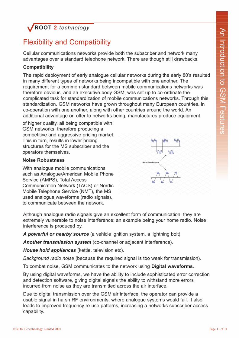
Although analogue radio signals give an excellent form of communication, they areextremely vulnerable to noise interference; an example being your home radio. Noiseinterference is produced by.
A powerful or nearby source (a vehicle ignition system, a lightning bolt).
Another transmission system (co-channel or adjacent interference).
House hold appliances (kettle, television etc).
Background radio noise (because the required signal is too weak for transmission).
To combat noise, GSM communicates to the network using Digital waveforms.
By using digital waveforms, we have the ability to include sophisticated error correctionand detection software, giving digital signals the ability to withstand more errorsincurred from noise as they are transmitted across the air interface.
Due to digital transmission over the GSM air interface, the operator can provide ausable signal in harsh RF environments, where analogue systems would fail. It alsoleads to improved frequency re-use patterns, increasing a networks subscriber accesscapability.
of higher quality, all being compatible withGSM networks, therefore producing acompetitive and aggressive pricing market.This in turn, results in lower pricingstructures for the MS subscriber and theoperators themselves.
Noise Robustness
With analogue mobile communicationssuch as Analogue/American Mobile PhoneService (AMPS), Total AccessCommunication Network (TACS) or NordicMobile Telephone Service (NMT), the MSused analogue waveforms (radio signals),to communicate between the network.
Page 11 of 11

ROOT 2 technology
© ROOT 2 technology Limited 2001
An Introduction to G
SM
Features
Increased Capacity
With the analogue air interface, every connection to the network required one RFcarrier. Old analogue systems typically used Frequency Division Multiple Access(FDMA) rather than Time Division Multiple Access (TDMA) in GSM. As we havealready discussed, TDMA has eight timeslots for transmission, where FDMA has onlyone, limiting control and more importantly, the number of subscribers that cansimultaneously access the network. FDMA networks required a greater number ofequipments, per cell, if capacity of the network was to increase. This made networkexpansion expensive and time consuming as many sites had to be configured and re-tuned manually, making the analogue system extremely inflexible. GSM equipmenthowever, overcomes many of these issues due to it being controlled primarily by itssoftware. The reconfiguration of the network can be implemented quickly, withminimum manually intervention, and by using TDMA, expansion can be implemented
with less equipment. In addition, GSM has standardised interfaces between networkcomponents, such as Signalling System No.7 (C7). Therefore, along with the radioequipment, upgrades to the entire network can be implemented with minimumdisruption, time delay and cost.
A key feature of GSM is that it offers the flexibility of International Roaming. Thispermits the MS subscriber to travel to foreign countries with GSM networks, and usetheir phones as if they were at home. If chosen too, a subscriber can choose only totake their Subscriber Identity Module (SIM) that we will discuss later, and hire a phonewhilst travelling abroad.
GSM’s use of a digital air interface makes it more resilient to interference thanhistorical analogue interfaces. It allows users on the same frequency or nearbyfrequencies to be co-located in closer geographical areas, decreasing the size of cells,making better use of ARFCN available within the re-use pattern. As GSM progresses,Multi-band networks and mobile phones now operate, operating within both frequencyspectrums of 900 MHz and 1800 MHz/1900 MHz. In order for this the mobile must becapable of working in dual band mode, to the user however this is transparent. Multi-band operation, allows the network greater flexibility in planning as it increases thenumber of frequencies available for the re-use pattern. It reduces interference andconsiderably increases the networks available or potential MS subscriber capacity.
Page 12 of 12
IncreasedCapacity“FDMA
requires up toeight times the
equipmentsthan that of a
TDMAnetwork”.
FDMATDMA
Timeslots

ROOT 2 technology
© ROOT 2 technology Limited 2001
An Introduction to G
SM
Features
Security and Services
Security was a major problem encountered with analogue networks. In some networks,it was virtually non-existent and the unscrupulous were quick to recognise this. It wasestimated that in some of the earliest networks, 20% of phone calls were stolen.Extensive measures have been taken within GSM to substantially increase securityfrom both theft of calls and theft of the physical phone itself. With GSM, both themobile phone equipment and the subscriber are identified, using separate identities,the mobile phone equipment being, International Mobile Equipment Identity (IMEI) andthe subscriber, International Mobile Subscriber Identity (IMSI). Both of these identitiesare stored within the network and will be discussed later in the course. In addition tothese identities, the GSM air interface supports Frequency Hopping; a process wherethe MS transmits on a different frequency each time it communicates with the network,making it extremely difficult for a hacker to listen to a specific call. Although frequencyhopping is used as an aid to security, it is also employed to optimise networkperformance, to counter interference aiding to cell quality and capacity.GSM offers anenhanced range of services compared to those available with analogue networks,ranging from data transmission options, fax and a wide range of supplementaryoptions. When services were specified for GSM, current land PSTN services had to betaken into consideration, with the services made available based upon three factors:
The level of service provided by the network.
The level of service purchased by the subscriber.
The capabilities of the subscriber’s mobile equipment.
Speech services involve the transmission of speech information making up the basicservice that a network would offer.
Telephony provides normal MS originated / terminated voice calls.
Short Message Service (SMS) provides the transmission of an acknowledged shortmessage from a service centre to the MS.
Short Message Cell Broadcast provides the transmission of a short message to allMS within a cell area.
Data services provide the ability to transmit text files, images, messages and fax overthe GSM network. Data rates available range from 2.4 kbit/s, 4.8 kbit/s, 9.6 kbit/s and14.4 kbit/s.
In addition to supporting data transmission, GSM provides Group 3 Fax transmission.
Supplementary services are additional services to a basic telecommunicationsservice, where an operator will charge extra for use of them.
Number Identification the receiving party requests that the number be shown.
Call Barring where incoming or outgoing calls can be barred.
Call Forwarding where calls can be forwarded to another number if the MS does notanswer, as an example.
Multi-party provisions for conference calling.
Page 13 of 13
ROOT 2 technology
© ROOT 2 technology Limited 2001
An Introduction to G
SM
Features
Key PointsFlexibility and Compatibility
Subscriber - Mobility, Flexibility, Convenience.
Network Provider - Network Expansion Flexibility, Revenue/Profit margins, Efficiencyand easier to Re-Configure.
Cellular Technology
Large cells are employed in the following areas:
1. Remote areas. 2. Coastal regions. 3. Areas with few MS subscribers.
Typical uses of small cells being:
1. Urban areas. 2. TX power requirements. 3. High number of MS subscribers.
Increased Capacity
The RF carrier is divided into eight Time Division Multiple Access (TDMA) timeslots,allowing each RF carrier the capability of supporting up to eight simultaneoustelephone calls.
Uplink and downlink frequencies are linked together forming a pair and are given thename Absolute Radio Frequency Channel Number (ARFCN).
To combat noise, GSM communicates to the network using Digital waveforms.
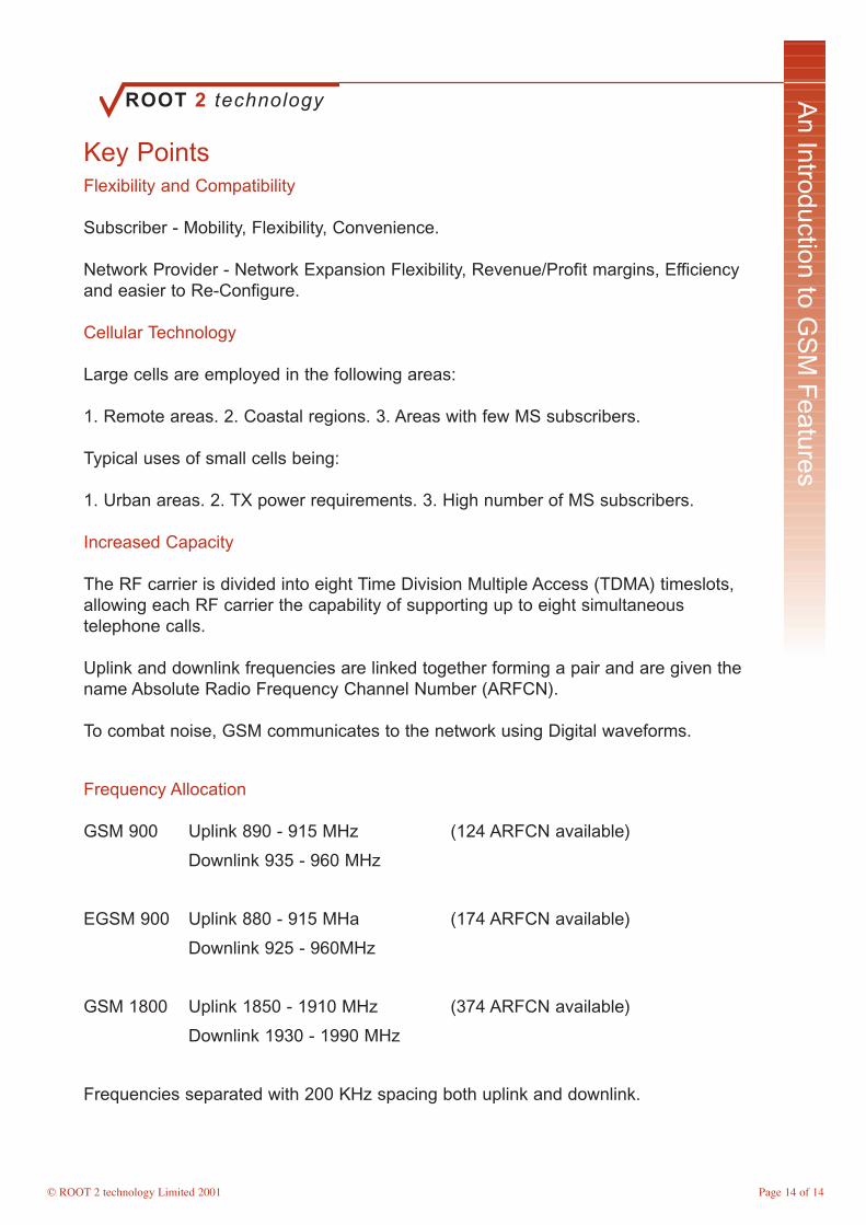
Frequency Allocation
GSM 900 Uplink 890 - 915 MHz (124 ARFCN available)
Downlink 935 - 960 MHz
EGSM 900 Uplink 880 - 915 MHa (174 ARFCN available)
Downlink 925 - 960MHz
GSM 1800 Uplink 1850 - 1910 MHz (374 ARFCN available)
Downlink 1930 - 1990 MHz
Frequencies separated with 200 KHz spacing both uplink and downlink.
Page 14 of 14

ROOT 2 technology
© ROOT 2 technology Limited 2001
The G
SM
Netw
ork
Module Objectives
On completion of this module of instruction the delegate will have gained anunderstanding of: -
• Identify the GSM Network Configuration• Discuss the functions of the Mobile Station• List Mobile Station configurations• Explore the characteristics of the SIM• Explain the operation of the BSS• Discuss the functions of the BTS• List BTS configurations• Discuss the functions of the BSC• Discuss the functions of the XCDR• Explain the operation of the NSS• Explain the operation of the MSC• Discuss the functions of the HLR• Discuss the functions of the VLR• Identify the requirements for GSM Network Databases

ROOT 2 technology
© ROOT 2 technology Limited 2001
The G
SM
Netw
ork
Network Configuration
As already discussed, the GSM network comprises of many different components(illustrated below), all being part of two core systems, the Network Switching System(NSS), to which the Operations and Maintenance System is interfaced, and the BaseStation Subsystem (BSS). The illustration shows only one occurrence of eachcomponent, but in reality, the network will consist of multiple components. Thecomponent groups being.
The Mobile Station (MS) – consisting of the Mobile Equipment (ME) and theSubscriber Identity Module (SIM).
The Base Station Subsystem (BSS) – provides the radio air interface between theMS and the network.
The Network Switching System (NSS) – consisting of the Mobile Switching Centre(MSC) and associated system control elements. Here interconnections between othernetworks such as the PSTN are controlled.
The Operations and Maintenance System – enables the network the ability tocontrol, configure and maintain the network from a central location.
NMC
OMC
PSTN
MSC
VLRHLR
AUC
EIR
IWF
EC
Operations& maintenancesystem
NetworkSwitchingSystem
XCDR
ME
SIM
BSC
BTS
BaseStationSystem
MobileStationInterface/connection
Typical GSMNetwork
Architectureconsisting of the
two coresystems, the
NetworkSwitching
System (NSS)and Base Station
Subsystem(BSS).
Each network component communicates over an Interface, being specified by GSMstandards, enabling a network the flexibility to use multi-vendor equipments (not beingrestricted to one product manufacturer).
Page 16 of 16

ROOT 2 technology
© ROOT 2 technology Limited 2001
The G
SM
Netw
ork
The Mobile Station (MS)
The Mobile Station (MS) consists of two separate components, the Mobile Equipment(ME) and an electronic smart card known as the Subscriber Identity Module (SIM)card. The ME is the physical hardware, the phone that the subscriber uses to accessthe network. This hardware has an identity number associated to it, unique to everymobile phone, called the International Mobile Equipment Identity (IMEI), enablingthe network to identify individual ME’s. The SIM card interfaces directly with the ME (itis not limited to one ME therefore being transferable between different ME’s). Thismodule identifies the mobile subscriber, identifying the services available to thatsubscriber, and again is a unique identity. This identity is called the InternationalMobile Subscriber Identity (IMSI). Regarding purchasing of these two components,the ME can be purchased from many stores, but the SIM has to be purchased directlyfrom, or an agent of the mobile network itself. By using these two separatecomponents, GSM has the flexibility of being able to raise a bill against the individualsubscriber using the IMSI, rather than the IMEI of the ME (remembering that any onecan use a ME, making it difficult to identify the individual subscriber making a call). TheME is the only component of the network that a subscriber is physically likely to see.There are three main types available to a subscriber.
Vehicle Mounted – these devices areinstalled within a vehicle and have theirantenna mounted to the outside of thevehicle.
Portable Mobile Unit – this equipmentmaybe hand held, but the unit uses anexternal antenna, not the antenna of thedevice itself.
Hand Portable Unit – the more commonlyused device, the everyday mobile phone.
Each ME is identified by a Class Mark, thatinforms the network of the ME’s maximumpower output, services it is able to supportand frequency capabilities. This information is transmitted to the network in the ME’sinitial message (when the ME is turned on). Class Mark information;
Revision – Identifies GSM phase specifications.
(GSM currently has progressed through three phases 1, 2 and presently 2+)
RF Power – The maximum power that the ME can transmit at.
(GSM handset power transmission ranges from 8 Watts through 5 Watts, 2 Watts and0.8 Watts)
Ciphering Algorithm (Security) – Indicates the type of algorithm that the ME uses.
(Phase 1 used only an A5 algorithm, with Phase 2 using A5/0 – A5/7 algorithms)
Frequency – Phase 2 and 2+ have the ability of transmitting in all GSM frequencyranges.
Short Messaging (SMS) – Phase 2 onward provides SMS for subscribers.
Page 17 of 17
1006

ROOT 2 technology
© ROOT 2 technology Limited 2001
The G
SM
Netw
ork
Subscriber Identity Module (SIM)
As previously mentioned, the SIM smart card interfaces directly into the ME giving anindividual subscriber their unique identity. The SIM contains several identities utilisedby the network for billing, locating and controlling the MS.
The International Mobile Subscriber Identity (IMSI) – the unique identifier of anindividual subscriber. Only ever transmitted to the network when the phone is initialised(turned on) or on request by the network.
The Temporary Mobile Subscriber Identity (TMSI) – an identity allocated to thesubscriber by the network on initialisation. This identity is used in replacement to theIMSI for added security and is changed periodically by the network.
Location Area Identity (LAI) – an identity allocated to a BSS, used by the network forpaging purposes (locating the whereabouts of the MS).
Subscriber Authentication Key (Ki) – used by the network during the authenticationprocess (registration on a network), and added security of transmission over the airinterface.
IMSI
Ki
MSISDN
TMSI
LAI
SERVICES
SIM
IMEI
The Mobile Station International Services Digital Network number (MSISDN) – theactually mobile telephone number, comprising of a Country Code, Network Code andStation Code e.g. 0044 773 675432.
Most information held on the SIM is protected, some information though inconstantlyupdated by the network, the LAI for example. As the MS roams throughout the networkthis identity will change, therefore being updated. The SIM itself has been designedwith high degrees of added security, some being imposed by the user in allocating apassword Personal Identity Number (PIN), similar to a pin code with a credit card. TheSIM card can also store addition information such as charging records if the operatormakes the services available. It also is responsible for algorithm calculations during theauthentication process.
Page 18 of 18

ROOT 2 technology
© ROOT 2 technology Limited 2001
The G
SM
Netw
ork
Base Station Subsystem (BSS)
The Base Station Subsystem (BSS) is the GSM system that provides and controls thephysical radio air interface (communication between the MS and the NSS). It consistsof three major network components.
The Base Transceiver Station (BTS) – this provides the physical radio air interfaceconnection between the MS and the GSM network.
The Base Station Controller (BSC) – the BSC is the controlling element of a BSS. Itcontrols all BTS that are present within a BSS, therefore controlling the air interfaceeven though it does not physically provide the connection to the MS.
The Transcoder (XCDR) – is used to reduce the rate at which traffic (voice/data) istransmitted across the air interface and will be discussed later in the course.
Transcoder
BaseStation
Site
MobileStation
SwitchingSubSystem
SIM
BaseStation
Controller
2Mbt x n
2Mbt x n
Base StationSubSystem“Normally the
size of a BTS isdefined by thenumber of RFcarriers, someof the largerones having
upto 24carriers”
The BSC provides the control for the BSS with functions being:
Controls all BTS within the BSS.
Switches traffic and signalling information between BTS and the NSS.
Connects Terrestrial Circuits and channels on the air interface.
Controls handover performed by the BTS under its control.
Any operational information required by the BTS will be forwarded under the control ofthe BSC, likewise information required by the NSS about/from the BTS will be obtainedby the BSC. The BSC connects radio channels from the air interface, to terrestrialcircuits between the BSS and the MSC via the use of a Digital Switching Matrix. It alsouses this matrix to perform handover between the BTS under its control withoutinvolving the MSC. Handover will be covered later in greater depth. The BTS providesthe following functions of the BSS.
Channel Coding / Decoding.
Timing advance, dependant on the MS location within the given geographical area.
Measurement reporting.
Power control, paging, frequency hopping, traffic channel management and encryptionare also functions of the BTS/BSC.
Page 19 of 19

ROOT 2 technology
© ROOT 2 technology Limited 2001
The G
SM
Netw
ork
BSS Configurations
The maximum number of BTS that a BSC can control is not specified within GSM, butindividual specifications of manufacturer’s equipment do vary.
The BTS maybe located at the same site as a BSC being ‘Co-located’, or located at adifferent site, ‘Remote’. It is common to find most BTS remotely configured due mainlyto their being a larger number of BTS within the network compared too BSC.
A BSS is configured using various topologies, Daisy chaining, Hub Spoke and Loopbeing a few.
The Daisy Chain – a BTS need not communicate directly with its controlling BSC, butvia another BTS or chain of BTS equipment. Daisy chaining reduces the number ofconnections required within a network and is cheap to implement, but can lead totransmission delay through the BSS.
BSS
BTS
BTS
BTS
TRX
BTS
HUB & SPOKE
BSS
BTS
TRX
BTS
TRX
BTS
TRX
BTS
TRX DAISY CHAIN
LOOP
Topologies haveboth advantages
anddisadvantages
when used withinNetworks.
The Loop – these increase the redundancy of connectivity within a network as eachBTS has a least two paths for communicating to the BSC.
Hub Spoke – a method used when initially commissioning a network. This topologyreduces connections but decreases network redundancy, as a great deal of emphasisis place on the reliability of ‘hub’ elements.
Page 20 of 20

ROOT 2 technology
© ROOT 2 technology Limited 2001
The G
SM
Netw
ork
Network Switching System (NSS)
The Network Switching System (NSS)controls the GSM network, carrying outthe physical switching functions,authentication procedures used forsecurity and overall Mobility Management(MM). Its main function is to managecommunications between the GSMnetwork and other telecommunicationsnetworks.The NSS comprises of manydifferent components, being;
Mobile Switching Centre (MSC)
Home Location Register (HLR)
Visitor Location Register (VLR)
Equipment Identity Register (EIR)
Authentication Centre (AUC)
Inter Working Function (IWF)
Echo Canceller (EC)
NMC
OMC
PSTN
(G)MSC
VLR
IWF
Operations& maintenance
system
NetworkSwitching
Sub system
HLR AUC
EIR
The Mobile Switching Centre (MSC)
The main function of the MSC is to provide all switching functions, the same as anytelephone network switch. However, because of the additional complications involvedin the control and security aspects of the GSM network and the wide range ofsubscriber features offered the MSC has to be capable of fulfilling many additionalfunctions.
The MSC carries out different functions depending upon its location within the GSMnetwork (as discussed earlier a GSM network will comprise of more than one MSC). Ifthe MSC provides an interface between the GSM network and the PSTN, it is knownas a Gateway Mobile Switching Centre (GMSC). Here additional network componentssuch as the EC and IWF are located providing speech and data connections betweenthe MS and adjoining networks. Both the IWF and EC can be considered as part of theMSC due to their functionality being required for switching.
The diagramshows a typicalNSSinterconnection.Note: - only oneof eachcomponent isshown where inreality, the GSMnetwork willhave multiplecomponents.
Page 21 of 21
ROOT 2 technology
© ROOT 2 technology Limited 2001
The G
SM
Netw
ork
Home Location Register (HLR)
The MSC provides services for all MS located within a given geographical area. Itsprovides all switching required for mobile terminated and originating calls. One MSC iscapable of providing service cover for a region with approximately one millioninhabitants (not all will connect to the network simultaneously though).
Functions of the MSC are listed below.
Call Processing – includes control of voice/data call setup, inter-BSS and inter-MSChandover, and MM for all subscribers within its given geographical area.
Operation and Maintenance – management of databases and monitoring of trafficmeasurements for GSM operation centres.
Inter-working – manages interfaces between the GSM network and connectingnetworks such as the PSTN.
Billing – collects call billing data relating to MS terminated and originating calls.
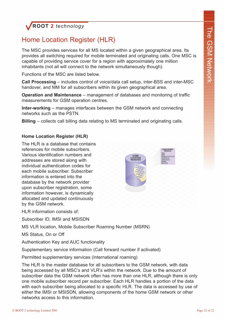
Home Location Register (HLR)
The HLR is a database that containsreferences for mobile subscribers.Various identification numbers andaddresses are stored along withindividual authentication codes foreach mobile subscriber. Subscriberinformation is entered into thedatabase by the network providerupon subscriber registration, someinformation however, is dynamicallyallocated and updated continuouslyby the GSM network.
HLR information consists of:
Subscriber ID, IMSI and MSISDN
MS VLR location, Mobile Subscriber Roaming Number (MSRN)
MS Status, On or Off
Authentication Key and AUC functionality
Supplementary service information (Call forward number if activated)
Permitted supplementary services (International roaming)
The HLR is the master database for all subscribers to the GSM network, with databeing accessed by all MSC’s and VLR’s within the network. Due to the amount ofsubscriber data the GSM network often has more than one HLR, although there is onlyone mobile subscriber record per subscriber. Each HLR handles a portion of the datawith each subscriber being allocated to a specific HLR. The data is accessed by use ofeither the IMSI or MSISDN, allowing components of the home GSM network or othernetworks access to this information.
Page 22 of 22
HOMELOCATIONREGISTER
IMSIIMEIMOBILE STATUSTRIPLETSSERVICESMSRNMSISDN
SUBSCRIBERPROFILE

ROOT 2 technology
© ROOT 2 technology Limited 2001
The G
SM
Netw
ork
Visitor Location Register (VLR)
Like the HLR the Visitor Location Register (VLR) is a database, but instead ofproviding permanent storage of data it only provides temporary storage. The dataexists for only as long as the MS is active within the given VLR area. It is thereforepossible that duplicate information can be present as well as the more precise datarelevant to a subscriber.
The VLR provides a local database for subscribers wherever they are geographicallylocated within the GSM network, whether being their home network or visiting network.The function of the VLR eliminates the requirement of constant communication with theHLR for subscriber references, reducing setup times and cost to the operator.
Additional data stored in the VLR:
Mobile status, busy/free/no answer etc
Location Area Identity (LAI)
Temporary Mobile Subscriber Identity (TMSI)
Mobile Station Roaming Number (MSRN)
Location Area Identity (LAI) – cells within the GSM network are grouped together intogeographical areas with each area being assigned an identity, a Location Area Identity,containing up to 30 cells. A VLR controls several LAI’s, so as a subscriber roams withinthe network the LAI will be updated within the VLR, therefore informing the network ofthe subscriber’s location. When required, the VLR address will be updated within theHLR.
Temporary Mobile Subscriber Identity (TMSI) – this identity is allocated by the VLRto use in replacement of the IMSI (by reducing the number of times that an IMSI istransmitted over the air interface, a GSM network increases a subscriber’s security).The TMSI is updated frequently, making it extremely difficult to trace calls, againproviding a high standard of security.
The TMSI is updated when:
During Call setup
On entry to a new LAI
On entry to a new VLR area
Mobile Station Roaming Number (MSRN) – this number is used for routing calls froman external network to an MS via the GMSC. The MSRN identifies the currentMSC/VLR area that a subscriber is connected too, therefore switching the call throughthe correct MSC. (Typically there will be a VLR co-located with each MSC within theGSM network, often being referred too as an MSC/VLR area.)
Page 23 of 23

ROOT 2 technology
© ROOT 2 technology Limited 2001
The G
SM
Netw
ork
Security Databases
Equipment Identity Register
As we have already discussed each MS has two identities, one of which being theIMEI. The Equipment Identity Register (EIR) is a centralized database that stores theIMEI of all subscribers on the GSM Network. The database concentrates on thephysical ME, and not the subscriber whom may be using it to make or receive calls.The EIR database comprises of three database lists being a specific IMEI list or rangeof IMEI numbers.
White List – this contains IMEI numbers of ME’s that have been allocated to a validsubscriber, that have not been reported stolen nor refused network services.
Black List – contains a list of IMEI numbers that have been bared by other networks,reported stolen, or denied access for what reason to network services.
Grey List – this list contains IMEI numbers that do not fall into either of the other twocatogories. E.g. limited services, hardware problems or customer payment delays.
The Database is continuously updatedby network programmers and by thenetwork obtaining information from acentral database to which all networkscan be connected (not all networks areconnected though). EIR’s are remotelyaccessed by an MSC/VLR during theauthentication process. If the IMEInumber is found in the black list theassociated MS will not be permittedaccess to the network, or any othernetwork containing the same EIRdatabase information.
Authentication Centre
The Authentication Centre (AUC) is a processing database that provides the GSMNetwork with security keys for the authentication procedure called Triplets, and isgenerally co-located with the HLR, as it is continuously requested to produce newauthentication keys for mobile subscriber records. The authentication procedure will bediscussed later in the course.
Interworking Function
The Interworking Function (IWF) provides a GSM Network the capability of interfacingwith private or public data networks. It consists of a bank of modems that act as theGSM Data Communication Equipment (DCE), exchanging data with a Data TerminalEquipment (DTE), an MS in the GSM network. It has two main functions:
Data Rate Adaption – provides data rate conversions (increasing / decreasing dataspeeds) for access to / from the GSM Network.
Protocol Conversion – ensures the correct protocol (communication tool) is used.
Certain networks may require additional IWF functionality, dependant on the type ofnetwork too which it is connected.
Page 24 of 24
EQUIPMENTIDENTITY
REGISTER
IMEI.xxx.xxxIMEI.xxx.xxxIMEI.xxx.xxxIMEI.xxx.xxxIMEI.xxx.xxxIMEI.xxx.xxxIMEI.xxx.xxx
WHITE LIST
IMEI.xxx.xxxIMEI.xxx.xxxIMEI.xxx.xxxIMEI.xxx.xxxIMEI.xxx.xxxIMEI.xxx.xxxIMEI.xxx.xxx
BLACK LIST
IMEI.xxx.xxxIMEI.xxx.xxxIMEI.xxx.xxxIMEI.xxx.xxxIMEI.xxx.xxxIMEI.xxx.xxxIMEI.xxx.xxx
GREY LIST

ROOT 2 technology
© ROOT 2 technology Limited 2001
The G
SM
Netw
ork
Module 2 Key Points
GSM Network Components
The Mobile Station (MS) – consisting of the Mobile Equipment (ME) and the SubscriberIdentity Module (SIM).
The Base Station Subsystem (BSS) – provides the radio air interface between the MSand the network.
The Network Switching System (NSS) – consisting of the Mobile Switching Centre(MSC) and associated system control elements. Here interconnections between othernetworks such as the PSTN are controlled.
The Operations and Maintenance System – enables the network the ability to control,configure and maintain the network from a central location.
SIM Card Identities
The International Mobile Subscriber Identity (IMSI)
The Temporary Mobile Subscriber Identity (TMSI)
Location Area Identity (LAI)
Subscriber Authentication Key (Ki)
The Mobile Station International Services Digital Network number (MSISDN)
BSS Components
The Base Transceiver Station (BTS)
The Base Station Controller (BSC)
The Transcoder (XCDR)
NSS Components
The Mobile Switching Centre (MSC)
Home Location Register (HLR)
Visitor Location Register (VLR)
Equipment Identity Register (EIR)
Authentication Centre (AUC)
Page 25 of 25

ROOT 2 technology
© ROOT 2 technology Limited 2001
GS
MTerrestrial Interfaces
Module Objectives
On completion of this module of instruction the delegate will have gained anunderstanding of: -
• Explore the differing Terrestrial Interfaces used within GSM• Discuss PCM Theory• Explain the structure of a 2Mbit Trunk• List the reasons for using ITU-T CCS No.7 Signalling• Explain the uses of CCS No.7 Protocols• Discuss the Link Access D Channel Protocol• Explain why LAPDm is used accross the Um Interface• Explore transmission rates accross the various GSM Interconnections

ROOT 2 technology
© ROOT 2 technology Limited 2001
GS
MTerrestrial Interfaces
Terrestrial Interfaces
The terrestrial interfaces comprise of all of the connections between the GSM networkcomponents, apart from the Um or air interface.
They are shown in the diagram below connecting the various components together.
The interfaces are the message transport mediums for GSM, all complying with ITU-Tspecifications (International Telecommunications Union - Telecoms). The use of thesestandards provides the flexibility that can be seen today within multi-platform GSMnetworks.
The terrestrial interfaces transport all of the messages throughout the system that arerequired to perform system functions.
Um - LAPDm Abis - LAPDA - BSSAP B - MAPC - MAP D - C7E - ISUP H - C7
D
F
H
OMC
VLR
EIR
AUC
MSC
BSC
HLR
BTS
UmAbis
A
B
C
They transport all data for software upand downloads, the collection ofstatistical information and messagesrequired for O&M operations(Maintenance and Control).
The standard interfaces used withinGSM are:
PCM 2 Mbit LinksSignalling System No.7 - (ITU-T SS7or CCS7)LAPD Protocol - Link AccessProtocol Data (D Channel)X.25 - (Packet Switch Data for OMCinterface)
Page 27 of 27
X.25Applications
X.25
LAPB
MTP (C7)
Abis
LAPD
2 Mbit Trunks
C7Applications
1
2
3
4 - 7
OSI LAYERS
ROOT 2 technology
© ROOT 2 technology Limited 2001
GS
MTerrestrial Interfaces
2 Mbit/s PCM 30 Trunks
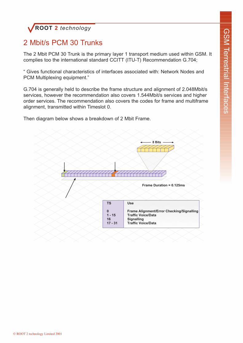
The 2 Mbit PCM 30 Trunk is the primary layer 1 transport medium used within GSM. Itcomplies too the international standard CCITT (ITU-T) Recommendation G.704;
“ Gives functional characteristics of interfaces associated with: Network Nodes andPCM Multiplexing equipment.”
G.704 is generally held to describe the frame structure and alignment of 2.048Mbit/sservices, however the recommendation also covers 1.544Mbit/s services and higherorder services. The recommendation also covers the codes for frame and multiframealignment, transmitted within Timeslot 0.
Then diagram below shows a breakdown of 2 Mbit Frame.
TS Use
0 Frame Alignment/Error Checking/Signalling1 - 15 Traffic Voice/Data16 Signalling17 - 31 Traffic Voice/Data
Frame Duration = 0.125ms
8 Bits
SignallingControlTS 0 TS 16
ITU-T G.704Frame Structure
The 2 Mbit Frame comprises of 32 Timeslots. Each Timeslot is 64Kbits in size,resulting in a total frame size of 2.048Mbits. Each 2 Mbit frame provides thirty channelsfor the transmission of speech, data or control information. The control information maycontain C7, LAPD or X.25 formatted information.
It is typical to find Timeslot 16 used for signalling information, but any timeslot can beused for this purpose. Some operators choose to use Timeslot 1 for signallingpurposes.
Timeslots are also referred to as D and B Channels (D Channel for signalling and BChannel for Traffic). If the 2Mbit frame is using C7 signalling, the D Channel cansupport signalling for 480 B Channels. If using Channel Associated Signalling (CAS),the D Channel can only support signalling for one frame (30 B Channels).
Page 28 of 28
ROOT 2 technology
© ROOT 2 technology Limited 2001
GS
MTerrestrial Interfaces
C7 Signalling
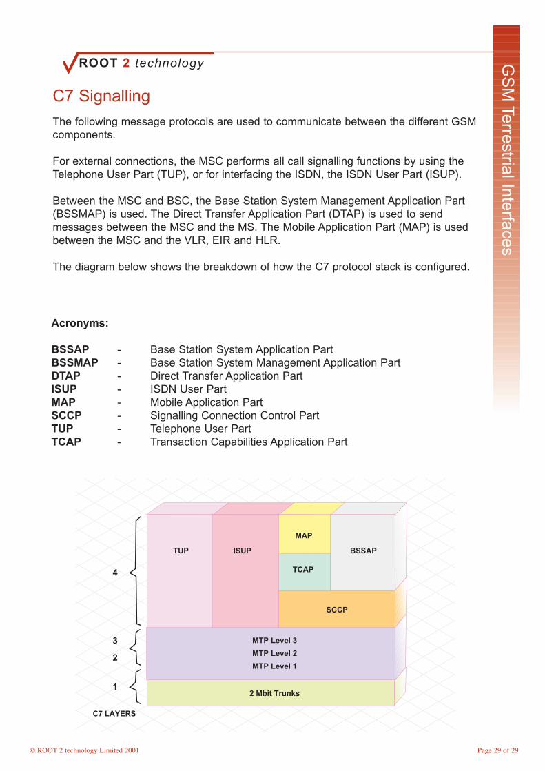
The following message protocols are used to communicate between the different GSMcomponents.
For external connections, the MSC performs all call signalling functions by using theTelephone User Part (TUP), or for interfacing the ISDN, the ISDN User Part (ISUP).
Between the MSC and BSC, the Base Station System Management Application Part(BSSMAP) is used. The Direct Transfer Application Part (DTAP) is used to sendmessages between the MSC and the MS. The Mobile Application Part (MAP) is usedbetween the MSC and the VLR, EIR and HLR.
The diagram below shows the breakdown of how the C7 protocol stack is configured.
TUP
1
2
3
4
C7 LAYERS
MTP Level 3
MTP Level 2
MTP Level 1
2 Mbit Trunks
ISUP
MAP
TCAP
SCCP
BSSAP
Acronyms:
BSSAP - Base Station System Application PartBSSMAP - Base Station System Management Application PartDTAP - Direct Transfer Application PartISUP - ISDN User PartMAP - Mobile Application PartSCCP - Signalling Connection Control PartTUP - Telephone User PartTCAP - Transaction Capabilities Application Part
Page 29 of 29
ROOT 2 technology
© ROOT 2 technology Limited 2001
GS
MTerrestrial Interfaces
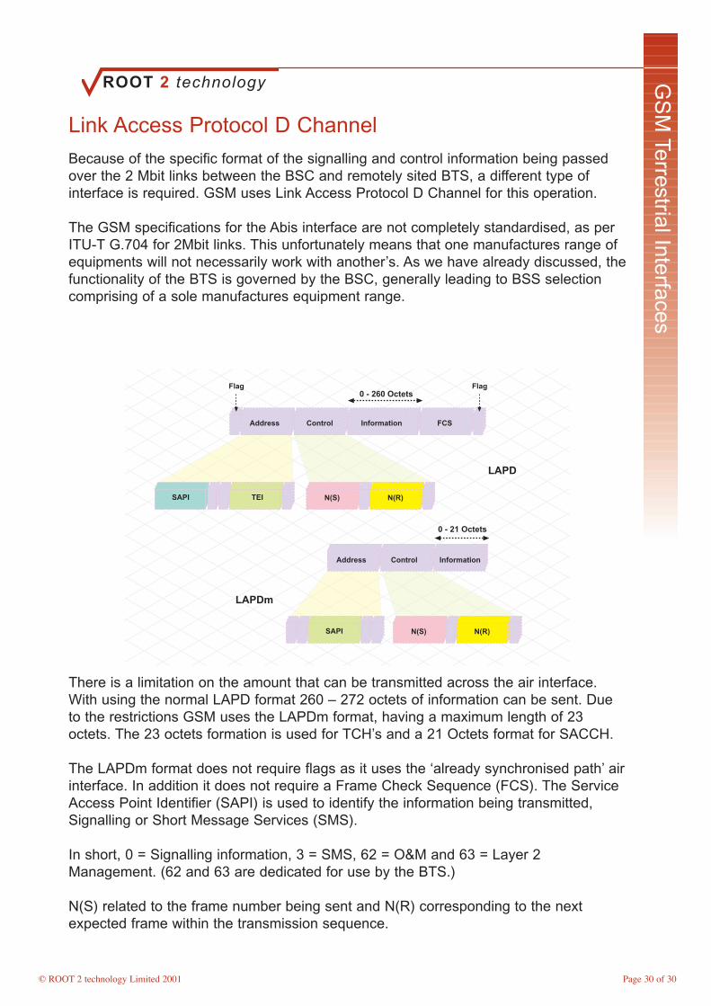
Link Access Protocol D Channel
Because of the specific format of the signalling and control information being passedover the 2 Mbit links between the BSC and remotely sited BTS, a different type ofinterface is required. GSM uses Link Access Protocol D Channel for this operation.
The GSM specifications for the Abis interface are not completely standardised, as perITU-T G.704 for 2Mbit links. This unfortunately means that one manufactures range ofequipments will not necessarily work with another’s. As we have already discussed, thefunctionality of the BTS is governed by the BSC, generally leading to BSS selectioncomprising of a sole manufactures equipment range.
0 - 260 Octets
Address Control Information FCS
Flag Flag
SAPI TEI N(S) N(R)
SAPI N(S) N(R)
0 - 21 Octets
Address Control Information
LAPD
LAPDm
There is a limitation on the amount that can be transmitted across the air interface.With using the normal LAPD format 260 – 272 octets of information can be sent. Dueto the restrictions GSM uses the LAPDm format, having a maximum length of 23octets. The 23 octets formation is used for TCH’s and a 21 Octets format for SACCH.
The LAPDm format does not require flags as it uses the ‘already synchronised path’ airinterface. In addition it does not require a Frame Check Sequence (FCS). The ServiceAccess Point Identifier (SAPI) is used to identify the information being transmitted,Signalling or Short Message Services (SMS).
In short, 0 = Signalling information, 3 = SMS, 62 = O&M and 63 = Layer 2Management. (62 and 63 are dedicated for use by the BTS.)
N(S) related to the frame number being sent and N(R) corresponding to the nextexpected frame within the transmission sequence.
Page 30 of 30

ROOT 2 technology
© ROOT 2 technology Limited 2001
GS
MTerrestrial Interfaces
Interconnections
The Interface between the BSC and MSC uses the standardised ITU-T CCS7interface, referred to as the A Interface.
The interface supports the following connections:
BSC - MSC, BSC - BTS and MSC - MS
Operations and Maintenance Interface
All call processing functions
These interfaces are commonly transported on a 2 Mbit/s link.
MSC
BSC
LAPD LAPD
MTL
OML (X.25)
OMC- R
BTS BTS BTS
Each 2 Mbit link provides 32, 64Kbit/s channels or Timeslots. Timeslot zero is alwaysused for control and frame alignment purposes, with one other being used forsignalling, typically Timeslot 16 and the remainder, used for traffic.
The signalling protocols used with a GSM Network are:
LAPD – 1 x 64Kbit/s timeslot
CCS7 – 1 x 64Kbit/s timeslot (BSSAP, MAP, TCAP, SCCP, MTP)
X.25 – 1 x 64Kbit/s timeslot (Used between the BSC and OMC)
CCS7 is used for transmission between the MSC and BSS, dependent upon the typeof signalling required, will depend on which signalling part is used. (DTAP is used forthe transfer of messages between the MSC and MS, a subset of BSSAP.)
Page 31 of 31
ROOT 2 technology
© ROOT 2 technology Limited 2001
GS
MTerrestrial Interfaces
Module 3 Key Points
Standard GSM Interfaces:
PCM 2 Mbit Links
Signalling System No.7 - (ITU-T SS7 or CCS7)
LAPD Protocol - Link Access Protocol Data (D Channel)
X.25 - (Packet Switch Data for OMC interface)
PCM 30
The 2 Mbit Frame comprises of 32 Timeslots. Each Timeslot is 64Kbits in size,resulting in a total frame size of 2.048Mbits. Each 2 Mbit frame provides thirty channelsfor the transmission of speech, data or control information. The control information maycontain C7, LAPD or X.25 formatted information.
C7 Protocols
BSSAP - Base Station System Application PartBSSMAP - Base Station System Management Application PartDTAP - Direct Transfer Application PartISUP - ISDN User PartMAP - Mobile Application PartSCCP - Signalling Connection Control PartTUP - Telephone User PartTCAP - Transaction Capabilities Application Part
LAPD
There is a limitation on the amount that can be transmitted across the air interface.With using the normal LAPD format 260 – 272 octets of information can be sent. Dueto the restrictions GSM uses the LAPDm format, having a maximum length of 23octets. The 23 octets formation is used for TCH’s and a 21 Octets format for SACCH.
Interfaces
The signalling protocols used with a GSM Network are:
LAPD – 1 x 64Kbit/s timeslot
CCS7 – 1 x 64Kbit/s timeslot (BSSAP, MAP, TCAP, SCCP, MTP)
X.25 – 1 x 64Kbit/s timeslot (Used between the BSC and OMC)
Page 32 of 32

ROOT 2 technology
© ROOT 2 technology Limited 2001
The R
adio Air Interface
Module Objectives
On completion of this module of instruction the delegate will have gained anunderstanding of: -
• Explain Modulation Techniques• Discuss the reasons for using TDMA Frames• Explore Physical Channels used within GSM• List the Logical Channels• Explain the Broadcast Control Channel• Explore all Common Control Channels• Explore all Dedicated control Channels• Define Mobile Access• Explain channels used for Handover• Examine the GSM Burst• List the GSM Burst Types• Identify the requirement for using Multi Frames • Define GSM Timing• Discuss the Speech Encoding process• Discuss the GSM Authentication Procedure
ROOT 2 technology
© ROOT 2 technology Limited 2001
The R
adio Air Interface
Modulation Techniques
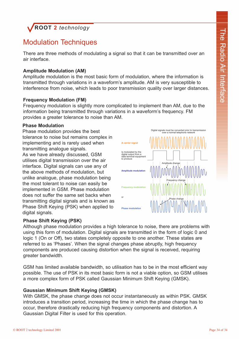
There are three methods of modulating a signal so that it can be transmitted over anair interface.
Amplitude Modulation (AM)Amplitude modulation is the most basic form of modulation, where the information istransmitted through variations in a waveform’s amplitude. AM is very susceptible tointerference from noise, which leads to poor transmission quality over larger distances.
Frequency Modulation (FM)Frequency modulation is slightly more complicated to implement than AM, due to theinformation being transmitted through variations in a waveform’s frequency. FMprovides a greater tolerance to noise than AM.
Digital signals must be converted prior to tramsmissionover a normal telephone network
A carrier signal
Is modulated by thedigital output from adata terminal equipmentto produce
Amplitude modulation
Frequency modulation
or
Phase modulation
Amplitude change
Frequency change
Phase change
Phase Shift Keying (PSK)Although phase modulation provides a high tolerance to noise, there are problems withusing this form of modulation. Digital signals are transmitted in the form of logic 0 andlogic 1 (On or Off), two states completely opposite to one another. These states arereferred to as ‘Phases’. When the signal changes phase abruptly, high frequencycomponents are produced causing distortion when the signal is received, requiringgreater bandwidth.
GSM has limited available bandwidth, so utilisation has to be in the most efficient waypossible. The use of PSK in its most basic form is not a viable option, so GSM utilisesa more complex form of PSK called Gaussian Minimum Shift Keying (GMSK).
Gaussian Minimum Shift Keying (GMSK)With GMSK, the phase change does not occur instantaneously as within PSK. GMSKintroduces a transition period, increasing the time in which the phase change has tooccur, therefore drastically reducing high frequency components and distortion. AGaussian Digital Filter is used for this operation.
Phase ModulationPhase modulation provides the besttolerance to noise but remains complex inimplementing and is rarely used whentransmitting analogue signals.As we have already discussed, GSMutilises digital transmission over the airinterface. Digital signals can use any ofthe above methods of modulation, butunlike analogue, phase modulation beingthe most tolerant to noise can easily beimplemented in GSM. Phase modulationdoes not suffer the same set backs whentransmitting digital signals and is known asPhase Shift Keying (PSK) when applied todigital signals.
Page 34 of 34
ROOT 2 technology
© ROOT 2 technology Limited 2001
The R
adio Air Interface
Physical Channels
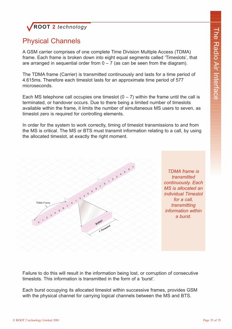
A GSM carrier comprises of one complete Time Division Multiple Access (TDMA)frame. Each frame is broken down into eight equal segments called ‘Timeslots’, thatare arranged in sequential order from 0 – 7 (as can be seen from the diagram).
The TDMA frame (Carrier) is transmitted continuously and lasts for a time period of4.615ms. Therefore each timeslot lasts for an approximate time period of 577microseconds.
Each MS telephone call occupies one timeslot (0 – 7) within the frame until the call isterminated, or handover occurs. Due to there being a limited number of timeslotsavailable within the frame, it limits the number of simultaneous MS users to seven, astimeslot zero is required for controlling elements.
In order for the system to work correctly, timing of timeslot transmissions to and fromthe MS is critical. The MS or BTS must transmit information relating to a call, by usingthe allocated timeslot, at exactly the right moment.
TDMA Frame
BURST
1 Timeslot
76
54
01
32
76
54
01
23
76
54
01
23
TDMA frame istransmitted
continuously. EachMS is allocated anindividual Timeslot
for a call,transmitting
information withina burst.
Failure to do this will result in the information being lost, or corruption of consecutivetimeslots. This information is transmitted in the form of a ‘burst’.
Each burst occupying its allocated timeslot within successive frames, provides GSMwith the physical channel for carrying logical channels between the MS and BTS.
Page 35 of 35
ROOT 2 technology
© ROOT 2 technology Limited 2001
The R
adio Air Interface
Logical Channels
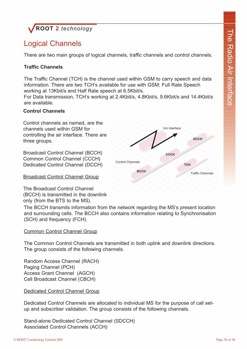
There are two main groups of logical channels, traffic channels and control channels.
Traffic Channels
The Traffic Channel (TCH) is the channel used within GSM to carry speech and datainformation. There are two TCH’s available for use with GSM; Full Rate Speechworking at 13Kbit/s and Half Rate speech at 6.5Kbit/s.For Data transmission, TCH’s working at 2.4Kbit/s, 4.8Kbit/s, 9.6Kbit/s and 14.4Kbit/sare available.
Um Interface
BCCH
CCCH
DCCH
Control Channels
Traffic Channels
TCH
The BCCH transmits information from the network regarding the MS’s present locationand surrounding cells. The BCCH also contains information relating to Synchronisation(SCH) and frequency (FCH).
Common Control Channel Group
The Common Control Channels are transmitted in both uplink and downlink directions.The group consists of the following channels.
Random Access Channel (RACH) Paging Channel (PCH) Access Grant Channel (AGCH) Cell Broadcast Channel (CBCH)
Dedicated Control Channel Group
Dedicated Control Channels are allocated to individual MS for the purpose of call set-up and subscriber validation. The group consists of the following channels.
Stand-alone Dedicated Control Channel (SDCCH)Associated Control Channels (ACCH)
Control Channels
Control channels as named, are thechannels used within GSM forcontrolling the air interface. There arethree groups.
Broadcast Control Channel (BCCH)Common Control Channel (CCCH) Dedicated Control Channel (DCCH)
Broadcast Control Channel Group
The Broadcast Control Channel(BCCH) is transmitted in the downlinkonly (from the BTS to the MS).
Page 36 of 36

ROOT 2 technology
© ROOT 2 technology Limited 2001
The R
adio Air Interface
Broadcast Control Channel
The Broadcast Control Channel (BCCH) is continuously transmitted by the BTS on theBCCH carrier. The MS monitors the BCCH periodically (at least once every 30seconds) when it is not associated in making or receiving a call, to obtain the followinginformation.
Location Area Identity (LAI)List of surrounding cells that the MS monitors for handover purposesFrequency information Power control informationAccess Control for Paging
Note: Additional information is transmitted within the BCCH.
Um Interface
SCH
FCCH
Broadcast Control Channel
BCCH
LAIBSICDTXCBCH
Frequency Correction (Control) Channel (FCCH)
This channel is frequently transmitted within timeslots on the BCCH carrier allowing theMS to tune its frequency to that being transmitted by the associated BTS.
Synchronisation Channel (SCH)
The Synchronisation Channel is utilised to enable the MS to synchronise with anassociated TDMA frame over the air interface. Synchronisation is key to the success ofthe air interface and is therefore essential when making or receiving a call.
The MS will monitor the BCCH carrier from surrounding cells, storing information fromthe six strongest cells. Again for the purpose of handover, if the MS should roam withinthe network, it has the necessary information stored to move between cells with easeand quickly resynchronise with the new cell.
The BCCH is transmitted at aconstant power, with its signalstrength being monitored bythe MS. The MS uses thispower monitoring to identify ifhandover is required (coveredlater in the course). Becauseof the importance of theBCCH carrier, if no trafficrequires transmitting, a‘dummy burst’ will betransmitted to ensurecontinuity over the airinterface.
Page 37 of 37

ROOT 2 technology
© ROOT 2 technology Limited 2001
The R
adio Air Interface
Common Control Channels
The Common Control Channel (CCCH) is responsible for transferring controllinginformation between all MS within a BTS area. This control is necessary forimplementing ‘Call Origination’ and ‘Paging’ functions.
Random Access Channel (RACH)
The Random Access Channel is used by the MS to gain access to the network. It isonly used in the uplink, when the MS requests to initiate a call or responds to a PCHsent by the network.
Um Interface
AGCH
CBCH
PCHRACH
Common Control Channel
Paging Channel (PCH)
The Network uses the Paging Channel in order to contact an MS (paging can beperformed using either the IMSI, TMSI or IMEI identities).
Access Grant Channel (AGCH)
This is used by the BTS to assign a Dedicated Control Channel to an MS, in responseto the receipt of a RACH from the MS. The MS will then move to the DCCH in order toproceed with the call set-up, or to respond with requested information, regardingLocation Area Updates or Short Messaging Services (SMS).
Cell Broadcast Channel (CBCH)
This channel is used by the network to transmit broadcast messages to all MS’s withina given cell. Although this channel really uses a DCCH to transmit the messages, it isconsidered a CCCH as all MS within the given cell can receive that message.
All MS frequently monitor both the BCCH and CCCH within their associated cell, bothbeing transmitted constantly on the carrier by the BTS.
Page 38 of 38

ROOT 2 technology
© ROOT 2 technology Limited 2001
The R
adio Air Interface
Dedicated Control Channels
Dedicated Control Channels (DCCH) are used to convey specific information over theair interface. GSM uses a Stand-alone Dedicated Control Channel (SDCCH) to passinformation across the air interface, working in both directions between the BTS andMS. This SDCCH carries information for call setup, the authentication process, locationupdating and SMS.
Associated Control Channels
These channels are associated with either the SDCCH or a TCH. They are used tocarry information associated with handover whilst a simultaneous process is beingcarried out by either an SDCCH or a TCH.
Um Interface
Dedicated Control Channels
FACCH
SACCH
SDCCH
Slow Associated Control Channel (SACCH)
This channel is used to convey power and timing information in the downlink andpasses Receive Signal Strength Indications (RSSI) and link quality reports from the MSin the uplink. SACCH is also used for the handover procedure when the MS is idle (notinvolved in a physical call).
Fast Associated Control Channel (FACCH)
The FACCH is used to perform handover and also authentication when an MS isinvolved in a physical call (having been allocated a TCH). It is transmitted within theburst of the TCH, containing specific information that is required for the handoverprocedure.
All of the control channels are required for system operation and have to sharetimeslots over the air interface just like MS’s using the limited TCH’s. By sharing thetimeslots, it allows efficient passing of control information without wasting valuablecapacity that can be used for carrying additional call traffic. We therefore organise thelimited timeslots over the air interface to carry either control or traffic information.
Page 39 of 39

ROOT 2 technology
© ROOT 2 technology Limited 2001
The R
adio Air Interface
GSM Burst Format
The diagram below shows the format of a GSM burst. It consists of differing elementsdependant upon the burst in use. The elements described below form a Normal Burst,used for transmitting Voice Call and Data information.
Info Field
There are two info fields within the normal burst. Each field contains 57 Bits ofinformation (Voice call or Data). If during the call procedure handover is required,FACCH steals one of these info fields (all 57 Bits) to transmit the specific information required.
0 1 2 3 4 5 6 7
TDMA Frame
INFO INFOTRAININGSEQUENCE
STEALING FLAGSTAIL BITSTAIL BITS
GUARD PERIOD GUARD PERIOD
148 Bits
156 Bits (0.577ms)
44
Training Sequence
This is used by the receiver to estimate the quality and transfer characteristics of thephysical path (air interface) between the MS and BTS. The training sequence consistsof 26 Bits of information.
Tail Bits
The tail bits act as flags, identifying the beginning and end of the burst.
Guard Period
This period is designed to allow both the BTS and MS additional time to receive anddecode the transmitted burst. The timeslot allows 0.577ms for the burst to besuccessfully transmitted, where actually the physical burst only requires 0.546ms. Thisdifference in time relates to 8 Bits or 0.031ms time difference between actually bursttransmission and the actually time available. This 8 Bit guard period can be transmittedat either the beginning, the end or in both areas of the burst format.
Stealing Flags
These flags compriseof a single bit eachand indicate whethercall or FACCHinformation is presentwithin the informationfield.
Page 40 of 40

ROOT 2 technology
© ROOT 2 technology Limited 2001
The R
adio Air Interface
Burst Types
The diagram below shows the five types of burst employed over the GSM air interface.All bursts, whatever type, consist of 156 Bits of information allowing them successfultransmission within the allotted 0.577ms timeslot.
The burst is a sequence of information bits transmitted by network components, wherethe timeslot is the specific period of time that the burst must arrive in order to besuccessfully decoded.
Normal Burst - the normal burst carries traffic and control channels both up anddownlink apart from those listed below.
Frequency Correction Burst - carries the FCCH in the downlink only, to correct thefrequency of the MS.
Synchronisation Burst - carries the SCH in the downlink only, to synchronise timingof the MS with the BTS and therefore Network.
ENCODED (39) SYNCHRONISATION SEQUENCE(64) ENCODED (39)
GUARD PERIOD (68.25)ENCRYPTED BITS(36)
SYNCH SEQUENCE(41)
156 Bits (0.577ms)
INFO (57) INFO (57)TRAININGSEQUENCE (26)TAIL BITS TAIL BITS
FIXED BITS (142) TAIL BITSTAIL BITS
TAIL BITS TAIL BITS
FIXED BITS (57) TRAININGSEQUENCE FIXED BITS (57)TAIL BITS TAIL BITS
TAIL BITS
TAIL BITS
Dummy Burst - this burst is transmitted to fill unused timeslots on the BCCH carrier(downlink only), to retain continuity over the air interface.
Access Burst - this burst is much shorter in duration than the other bursts described.It has an increased guard period due to the time of transmission being unknown. Whenan Access Burst is transmitted, the BTS does not know the exact location of the MS,so therefore cannot accurately identify the timing of the message. The use of the largerguard period counters this problem.
Page 41 of 41
ROOT 2 technology
© ROOT 2 technology Limited 2001
The R
adio Air Interface
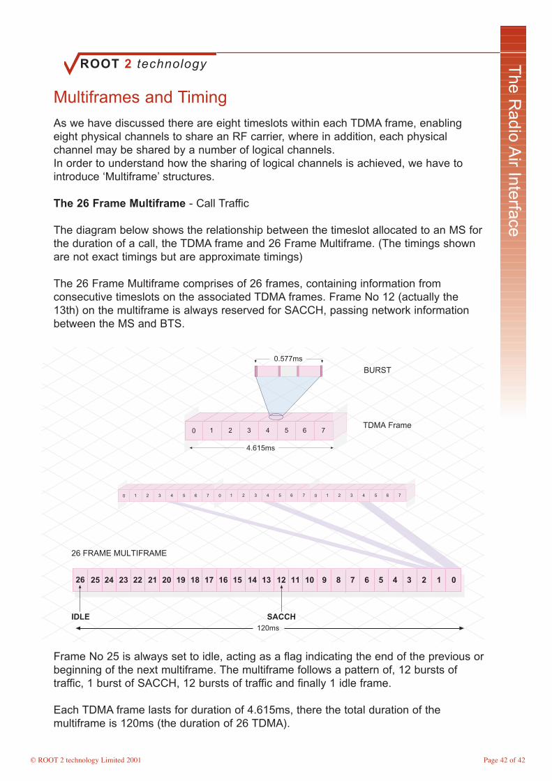
Multiframes and Timing
As we have discussed there are eight timeslots within each TDMA frame, enablingeight physical channels to share an RF carrier, where in addition, each physicalchannel may be shared by a number of logical channels.In order to understand how the sharing of logical channels is achieved, we have tointroduce ‘Multiframe’ structures.
The 26 Frame Multiframe - Call Traffic
The diagram below shows the relationship between the timeslot allocated to an MS forthe duration of a call, the TDMA frame and 26 Frame Multiframe. (The timings shownare not exact timings but are approximate timings)
The 26 Frame Multiframe comprises of 26 frames, containing information fromconsecutive timeslots on the associated TDMA frames. Frame No 12 (actually the13th) on the multiframe is always reserved for SACCH, passing network informationbetween the MS and BTS.
26 FRAME MULTIFRAMEE
0 1 2 3 4 5 6 7
0 1 2 3 4 5 6 7 0 1 2 3 4 5 6 7 0 1 2 3 4 5 6 7
BURST
01234567891011121314151617181920212223242526
TDMA Frame
SACCHIDLE
4.615ms
0.577ms
120ms
Frame No 25 is always set to idle, acting as a flag indicating the end of the previous orbeginning of the next multiframe. The multiframe follows a pattern of, 12 bursts oftraffic, 1 burst of SACCH, 12 bursts of traffic and finally 1 idle frame.
Each TDMA frame lasts for duration of 4.615ms, there the total duration of themultiframe is 120ms (the duration of 26 TDMA).
Page 42 of 42
ROOT 2 technology
© ROOT 2 technology Limited 2001
The R
adio Air Interface
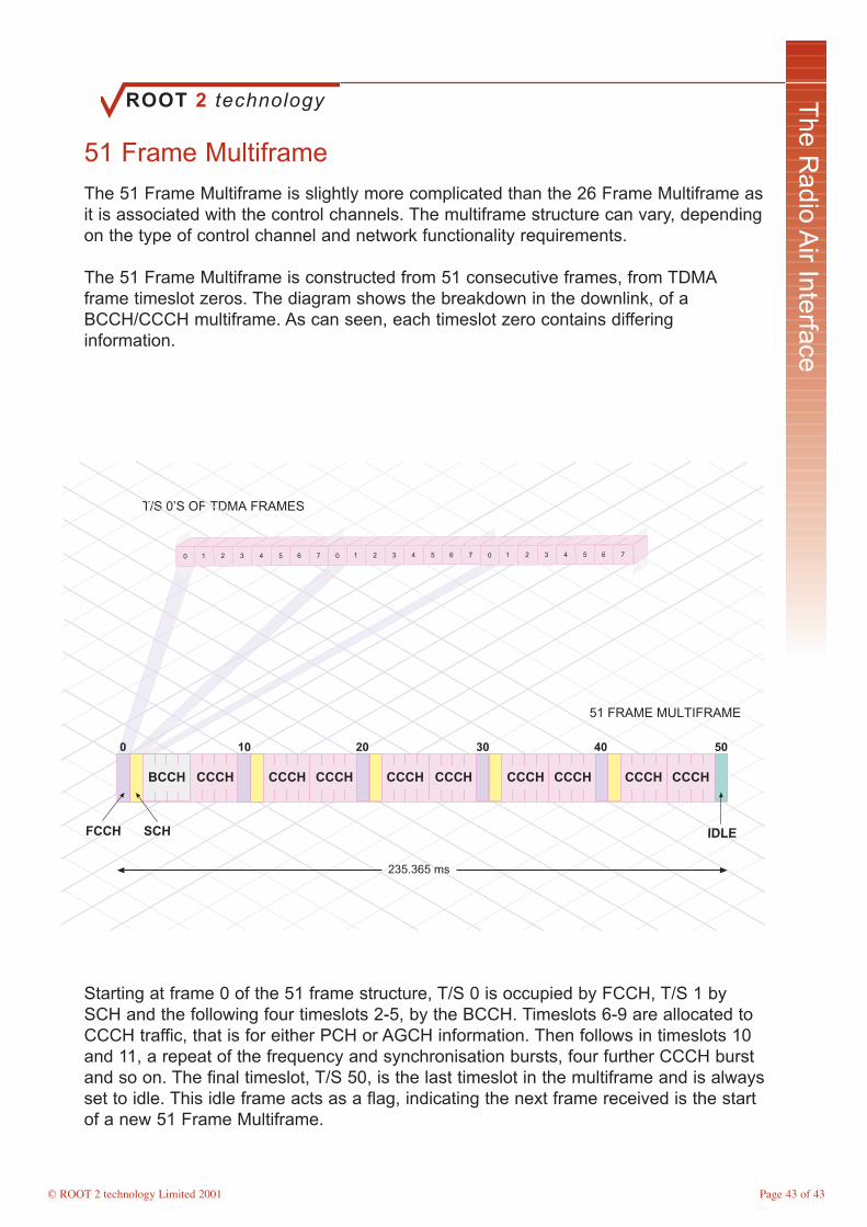
51 Frame Multiframe
The 51 Frame Multiframe is slightly more complicated than the 26 Frame Multiframe asit is associated with the control channels. The multiframe structure can vary, dependingon the type of control channel and network functionality requirements.
The 51 Frame Multiframe is constructed from 51 consecutive frames, from TDMAframe timeslot zeros. The diagram shows the breakdown in the downlink, of aBCCH/CCCH multiframe. As can seen, each timeslot zero contains differinginformation.
51 FRAME MULTIFRAME
T/S 0’S OF TDMA FRAMES
0 1 2 3 4 5 6 7 0 1 2 3 4 5 6 7 0 1 2 3 4 5 6 7
235.365 ms
IDLE
BCCH CCCH CCCH CCCH CCCH CCCH CCCH CCCH CCCH CCCH
0 10 20 30 40 50
FCCH SCH
Starting at frame 0 of the 51 frame structure, T/S 0 is occupied by FCCH, T/S 1 bySCH and the following four timeslots 2-5, by the BCCH. Timeslots 6-9 are allocated toCCCH traffic, that is for either PCH or AGCH information. Then follows in timeslots 10and 11, a repeat of the frequency and synchronisation bursts, four further CCCH burstand so on. The final timeslot, T/S 50, is the last timeslot in the multiframe and is alwaysset to idle. This idle frame acts as a flag, indicating the next frame received is the startof a new 51 Frame Multiframe.
Page 43 of 43
ROOT 2 technology
© ROOT 2 technology Limited 2001
The R
adio Air Interface
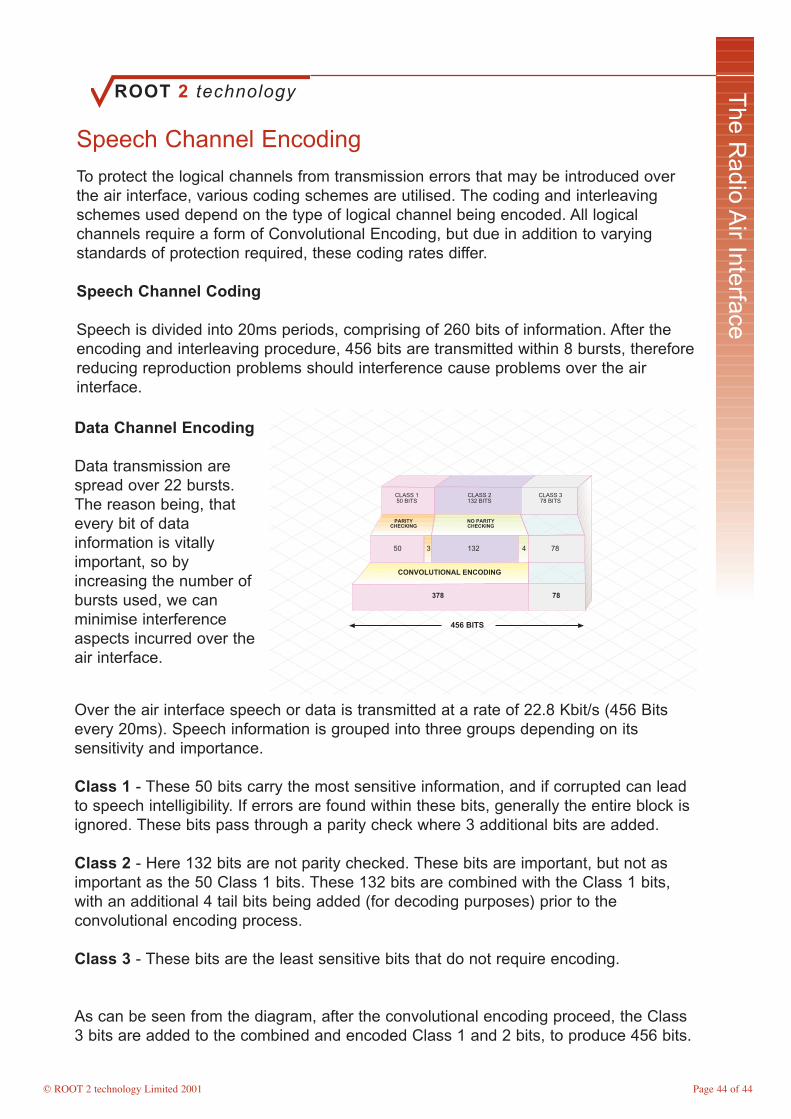
Speech Channel Encoding
To protect the logical channels from transmission errors that may be introduced overthe air interface, various coding schemes are utilised. The coding and interleavingschemes used depend on the type of logical channel being encoded. All logicalchannels require a form of Convolutional Encoding, but due in addition to varyingstandards of protection required, these coding rates differ.
Speech Channel Coding
Speech is divided into 20ms periods, comprising of 260 bits of information. After theencoding and interleaving procedure, 456 bits are transmitted within 8 bursts, thereforereducing reproduction problems should interference cause problems over the airinterface.
CONVOLUTIONAL ENCODING
CLASS 150 BITS
CLASS 2132 BITS
CLASS 378 BITS
50 1323 4 78
PARITYCHECKING
NO PARITY CHECKING
378 78
456 BITS
Over the air interface speech or data is transmitted at a rate of 22.8 Kbit/s (456 Bitsevery 20ms). Speech information is grouped into three groups depending on itssensitivity and importance.
Class 1 - These 50 bits carry the most sensitive information, and if corrupted can leadto speech intelligibility. If errors are found within these bits, generally the entire block isignored. These bits pass through a parity check where 3 additional bits are added.
Class 2 - Here 132 bits are not parity checked. These bits are important, but not asimportant as the 50 Class 1 bits. These 132 bits are combined with the Class 1 bits,with an additional 4 tail bits being added (for decoding purposes) prior to theconvolutional encoding process.
Class 3 - These bits are the least sensitive bits that do not require encoding.
As can be seen from the diagram, after the convolutional encoding proceed, the Class3 bits are added to the combined and encoded Class 1 and 2 bits, to produce 456 bits.
Data Channel Encoding
Data transmission arespread over 22 bursts.The reason being, thatevery bit of datainformation is vitallyimportant, so byincreasing the number ofbursts used, we canminimise interferenceaspects incurred over theair interface.
Page 44 of 44

ROOT 2 technology
© ROOT 2 technology Limited 2001
The R
adio Air Interface
GSM Authentication
One of the major drawbacks with analogue systems was the ease that an air interfacetransmission could be compromised.
GSM uses an Authentication Centre (AUC) Database for providing a network’s securityelements. It provides the network the ability to monitor a users access rights for callsetup, location updating and activation of supplementary services.
When a subscriber first purchases a phone from a provider, the network Ki key will beallocated to their IMSI. On initial setup (first activation), the Ki will be opened and onlythen is susceptible to copying.
Ki
RAND
SRES
Kc
A3Algorithm
A8Algorithm
RAND
TRIPLET
Ki
RAND
SRES
Kc
TRIPLET
A3Algorithm
A8Algorithm
RANDBTS
RAND
SRESSRES
RAND
TRIPLET
SRESSRES
SIM
AuCHLR
MSC/VLR
Triplets
Triplets are produced by the AUC for use throughout the authentication procedure.They consist of three separate elements, the Random Number (RAND), a SignedResponse (SRES) and a Key Code (Kc). The AUC produces these triplets through theuse of two algorithms, an A3 and an A8, both of which are matched with the samealgorithms on the SIM. Due to both network algorithms being assigned to the AUC andNetwork SIM cards, when the RAND used by the AUC in producing the Triplet ispassed to the MS for authentication, the MS in turn should produce the same Tripletresults. The MS produces the triplet and returns either the SRES or Kc (depending onrequest) to the VLR, where results are processed and authentication granted. If theresults differ, the MS will not be granted access.
Page 45 of 45

ROOT 2 technology
© ROOT 2 technology Limited 2001
The R
adio Air Interface
Module 4 Key Points
Modulation Types
Amplitude Modulation (AM)
Frequency Modulation (FM)
Phase Shift Keying (PSK)
Gaussian Minimum Shift Keying (GMSK)
Control Channels
Broadcast Control Channel (BCCH)Common Control Channel (CCCH) Dedicated Control Channel (DCCH)
BCCH
Location Area Identity (LAI)List of surrounding cells that the MS monitors for handover purposesFrequency information Power control informationAccess Control for Paging
GSM Bursts
Normal Burst Frequency Correction Burst Synchronisation BurstDummy Burst Access Burst
Multi Frames
The 26 Frame Multiframe - Call TrafficThe 51 Frame Multiframe - Signalling
Authentication
Triplets are produced by the AUC for use throughout the authentication procedure.They consist of three separate elements, the Random Number (RAND), a SignedResponse (SRES) and a Key Code (Kc).
Page 46 of 46

ROOT 2 technology
© ROOT 2 technology Limited 2001
Air Interface O
ptimisation
Module Objectives
On completion of this module of instruction the delegate will have gained anunderstanding of: -
• Explain the requirement for Timing Advance• Discuss Timeslot allocation• List GSM elements associated with Power Control• Describe DRX and its uses• Explore Multipath Fading• Discuss Antenna Diversity• Explain GSM Equalisation• Define Frequency Hopping and reasons for its use

ROOT 2 technology
© ROOT 2 technology Limited 2001
Air Interface O
ptimisation
Transmission Timing Advance
To simplify the design of the MS, by it not having to transmit and receive informationsimultaneously, GSM offsets the timing between TDMA frames. GSM specificationsstate that a timing offset of three timeslots must be incorporated. The diagram belowshows an example of this. Timing advance is not required on the BTS due to beingconfigured for simultaneous transmission and reception.
The synchronisation of TDMA frames is critical due to bursts having to be transmittedand received within ‘real time’ timeslots allocated to them. The further that the MS isfrom the BTS the longer it takes for the burst to be transmitted between them. The BTScaters for this problem by instructing the MS to advance its timing (to transmit earlier)to compensate for this increased delay.
0 1 2 3 4 5 6 7
0 1 2 3 4 5 6 7
FRAME 1
FRAME 1
DOWNLINK
UPLINK
BTS - MS
MS - BTS
3 TS OFFSET
TIMING ADVANCE
2 30 1
Timing advance information is sent to the MS twice every second using the SACCH(the 13th frame on the 26 Frame Multiframe). This advance is superimposed upon thetimeslot offset, again being shown in the diagram.
If the network is configured for a maximum cell size with a radius of approximately35km, the maximum timing advance will be approximately 0.233ms.
Page 48 of 48
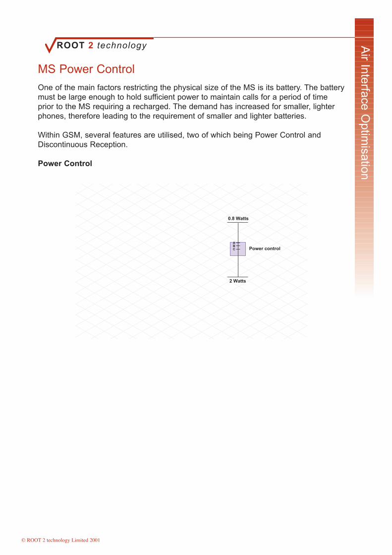
ROOT 2 technology
© ROOT 2 technology Limited 2001
Air Interface O
ptimisation
MS Power Control
One of the main factors restricting the physical size of the MS is its battery. The batterymust be large enough to hold sufficient power to maintain calls for a period of timeprior to the MS requiring a recharged. The demand has increased for smaller, lighterphones, therefore leading to the requirement of smaller and lighter batteries.
Within GSM, several features are utilised, two of which being Power Control andDiscontinuous Reception.
Power Control
ABC Power control
0.8 Watts
2 WattsBTS
0.8 Watts
1 Watt
1.4 Watts
This is a feature of the air interface, allowing the network not only to compensate forthe timing distance, but additional to allow the MS to control its power output incomparison to the distance required for successful transmission to the BTS. The closerthe MS is to the BTS, the less power required to transmit that distance, thereforeincreasing the MS’s battery life. In addition to saving power, by reducing in accordanceto distance it aids in the reduction of air interface interference (reducing co-channeland adjacent channel interference).
Both Uplink and Downlink power setting can be controlled, typically though the BTS willtransmit at a continuous power setting. (A BTS controls multiple MS so by adjustingpower settings to compensate for an individual MS it could seriously affect others.)
The BSS controls the power of both the MS and BTS. It monitors the receive power ofboth the MS and BTS, with reports being sent to the BSS, adjusting power settingaccordingly.
Page 49 of 49

ROOT 2 technology
© ROOT 2 technology Limited 2001
Air Interface O
ptimisation
Discontinuous Reception
Discontinuous Reception (DRX) allows the MS to ‘switch off’ when information beingtransmitted is not intended for it.
By the MS monitoring the BCCH, the FCCH and SCH, the MS is exactly aware of theframe number and format, and can identify where the information relevant is beingtransmitted. With the MS knowing this information, it can ‘switch off’ through the timeperiod where the information being transmitted is not meant for its reception, againsaving on battery life.
When DRX is used, the BCCH informs the MS of which Paging Group it is to listen too.This Paging Group may appear at the same time during every multiframe, or onceduring a series of multiframe transmissions. (The Network specifies multiframetransmission.)
BCCH C0 C1 C2 C3 C4 C5 C6 C7 C8
BCCH C0 C1 C2 C3 C4 C5 C6 C7 C8
BCCH C0 C1 C2 C3 C4 C5 C6 C7 C8
BCCH C18 C19 C20 C21 C22 C23 C24 C25 C26
BCCH C9 C10 C11 C12 C13 C14 C15 C16 C17
235 ms
470 ms
705 ms
C5 on Combined Multiframes
235.365 ms
MS Paged during C1once every 235ms Or
MS Pagedonce every 705ms
DRX may only be used when the MS is in an idle state, not physically making orreceiving a call.
Page 50 of 50

ROOT 2 technology
© ROOT 2 technology Limited 2001
Air Interface O
ptimisation
Multipath Fading
Multipath Fading results from a signal travelling to a receiver over a multiple number ofroutes. This can be caused by, the signal being reflected off of objects such asbuildings, or its path being altered by atmospheric pressures, such as weather.
Received signals will therefore arrive at differing times and possibly out of phase withone another. On arrival at the receiver, the signals combine either constructively ordestructively. The worst possible effect will be that the received signals arrive 180∞ outof phase with each other, therefore cancelling each other out. If this happens the resultis zero signal. Within the GSM frequency bands, a distance of approx 15cm may be allthat is required to alternate from a good, to a bad signal.
To over come this variation, GSM adopts several techniques to counter MultipathFading.
Buildings
BSS
Mulitiple Paths
MS
As the MS moves, the exact phase of the receive path will change. With this constantchange, the combination of received signal strength will also change, continuously.
The diagram shows an example of differing routes that a signal may take in travellingfrom a BTS to an MS.
Each of the paths has suffered a varying number of losses through transmission;hence a variation in received signal amplitudes.
Equalisation
Diversity
Frequency Hopping
Interleaving
Channel Coding
Page 51 of 51

ROOT 2 technology
© ROOT 2 technology Limited 2001
Air Interface O
ptimisation
Equalisation
Due to signal distortion caused through multipath fading, a receiver cannot be sureexactly when a burst will arrive. To aid in identification, a Training Sequence Code istransmitted at the centre of each burst. This is a set combination of bits, known by boththe transmitter and receiver.
When a burst of information is received, the equaliser searches for the trainingsequence code to identify how distorted it has become. It will then be able to identifythrough comparison, how distorted the remainder of the burst has become and identifythe most probable signal outcome.
There are eight different Training Sequence Codes used within GSM, numbered 0 to 7.Nearby cells, although operating on the same frequency will use different trainingsequence codes, therefore reducing additional air interface interference bydisregarding foreign bursts.
=> 10 Wave Lengths
COMBINER
Diversity
Intelligent Result of Combiner
GUARD PERIOD GUARD PERIODINFO INFOTRAININGSEQUENCE
NORMAL BURST
STEALING FLAGSTAIL BITSTAIL BITS
Diversity
As we have discussed, signals arrive at an antenna from multiple paths. The signalsare therefore received in different phases and at different strengths, meaning somesignals will combine to produce strong signals and others, subtract producing weak orno signal.
When diversity is implemented within GSM, two receive antennas are used. These twoantennas are placed several wavelengths apart, ensuring that there is minimumcorrelation between the two receive paths. The two received signals are combined atthe BTS, producing the most intelligent and strongest signal possible from the tworeceived signals (one from each of the receive antennas).
Page 52 of 52
ROOT 2 technology
© ROOT 2 technology Limited 2001
Air Interface O
ptimisation
Frequency Hopping
Frequency Hopping is used within GSM to limit the effects caused by multipath fading.It allows the MS to change the ARFCN used for each transmission (every 4.615ms),using the same timeslot, but different carrier. This provides a high degree of immunityto interference, due to interference averaging, as well as providing protection againstsignal fading.
Interference Averaging – assumes that radio channel interference does not exist onevery allocated ARFCN due to the MS changing to a new ARFCN every 4.615ms orframe. Therefore, the overall communication received only experiences interferencepart of the time.
BSS
0 1 2 3 4 5 6 7
01
23
45
67
0 12
34
56
7
ARFCN 41
ARFCN 44
ARFCN 47
HSN - ARFCN Sequence order
MAIO - Sequence start position
All mobile subscribers can use frequency hopping, which is controlled by the BSS. TheBSS provides the MS with two identities, a Hopping Sequence Number (HSN), theorder in which the MS hops through the available ARFCN’s and a Mobile AllocationIndex Offset (MAIO), the start point within the ARFCN hopping sequence. Not all cellssupport frequency hopping, so networks are configured for frequency hopping andallocated cells.
Page 53 of 53

ROOT 2 technology
© ROOT 2 technology Limited 2001
Air Interface O
ptimisation
Module 5 Key Points
Timing Advance
The synchronisation of TDMA frames is critical due to bursts having to be transmittedand received within ‘real time’ timeslots allocated to them. The further that the MS isfrom the BTS the longer it takes for the burst to be transmitted between them. The BTScaters for this problem by instructing the MS to advance its timing (to transmit earlier)to compensate for this increased delay.
Power Control
Both Uplink and Downlink power setting can be controlled, typically though the BTS willtransmit at a continuous power setting. (A BTS controls multiple MS so by adjustingpower settings to compensate for an individual MS it could seriously affect others.)
Discontinuous Reception (DRX)
Discontinuous Reception (DRX) allows the MS to ‘switch off’ when information beingtransmitted is not intended for it.
Multipath Fading
GSM utilises the following processes to limit Multipath fading:
Equalisation
Diversity
Frequency Hopping
Interleaving
Channel Coding
Page 54 of 54
ROOT 2 technology
© ROOT 2 technology Limited 2001
Call and H
andover Proceedures
Module Objectives
On completion of this module of instruction the delegate will have gained anunderstanding of: -
Mobile to PSTN Call
• Discuss the Mobile to PSTN call procedure• Explain key stages of the procedure
PSTN to Mobile Call
• Discuss the Mobile to PSTN call procedure• Explain key stages of the procedure
Inter BSS Handover
• Discuss the procedure taken during a GSM Handover• Explain key stages of the procedure
Location Updates
• Discuss the procedure for Location Updates • Explain key stages of the procedure
Authentication Procedure
• Explore the procedure and reasons for Authentication
ROOT 2 technology
© ROOT 2 technology Limited 2001
Call and H
andover Proceedures
Mobile to PSTN Call
1. The MS requests service by sending a RACH to the BSS. The BSS then assigns aDedicated Control Channel, SDCCH to the MS by using an AGCH.
2. The request for service (Call Request message - CR) is passed to the MSC, whichin turn relays the message to the VLR (At this stage the VLR can initiate theauthentication process if required where it will obtain parameters for the HLR).
3. The MSC then sends a Call Complete Message (CC) to the BSS for set up initiation,which in turn notifies the MS to proceed with the call.
4. The MSC accesses the PSTN with an Address Request Message (AR). The PSTNnegotiates with the called number and responds with an Address Complete Message(AC).
AR
AC
TCH
PSTN
SDCCH
SDCCH
RACH
AGCH
SDCCH
TCH
FACCH
SDCCH BSS
CC
CR
MSCTCH
5. The MSC informs the BSS to assign a TCH to the MS for the call.
6. Upon completion of this allocation the TCH is connected between the MS and callednumber, where billing of the call commences.
7. Throughout the duration of the call, FACCH is used to monitor the status of the TCHin case a Handover is required.
Page 56 of 56

ROOT 2 technology
© ROOT 2 technology Limited 2001
Call and H
andover Proceedures
PSTN to Mobile Call
1. The PSTN through the use of C7 Messaging contacts the GMSC with an MSISDN.
2. The GMSC passes the MSISDN to the HLR and responses with an MSRN (theidentity of the MSC/VLR area to which requested MS is attached).
3. The controlling MSC then informs the BSS to page the MS using a PCH.
4. The MS responds to the PCH with a RACH. The BSS then assigns a DedicatedControl Channel, SDCCH to the MS by using an AGCH.
5. Upon completion of this proceed (including authentication if required), the MSCsends an Address Complete Message (AC) to the PSTN.
PSTN
TCH
GMSC
MSISDNMSISDN
MSRN
MSRN
AC
ANS
MSC
BSS
RACH
AGCH
SDCCH
TCH
FACCH
SDCCH
PCH
HLR/VLR
6. The MSC then informs the BSS to assign a TCH to the MS for the duration of thecall.
7. The PSTN sends an Answer Message (ANS) to the MSC confirming connection.
8. The TCH is then connected and the call is established.
9. Throughout the duration of the call, FACCH is used to monitor the status of the TCHin case a Handover is required.
Page 57 of 57

ROOT 2 technology
© ROOT 2 technology Limited 2001
Call and H
andover Proceedures
Inter BSS Handover
While the MS is involved in a call (i.e. has a TCH allocated), it is continuouslycompiling measurements and reporting to the BSS.
1. When a Handover is required, typically due to low Receive Signal StrengthIndication (RSSI), the originating BSS (oBSS) notifies the MSC.
2. The MSC then targets the new BSS (nBSS) for the MS, through its TMSI.
3. The nBSS assigns a new TCH for the MS to use and passes relevant informationback to the MSC.
nBSS
oBSS
MSCFACCH
FACCH
SACCH
Inter BSS Handover
2. HO RequestInfo
3. HO Complete
1. HO Required
4. Clear Down
SACCH
FACCH
4. The MSC, via the oBSS orders the MS to change to the nBSS using FACCH.
5. The nBSS communicates with the MS Using FACCH to establish full connection.
6. Once all necessary information has been transferred the MSC is informed andHandover is complete.
7. The MSC now sends a Clear Down command to the oBSS, freeing the radioresource for another MS to use (The channel is not cleared until the nBSS can fullyaccommodate the MS).
8. Upon completion, the MS continues to periodically measure the RSSI values andreports to the nBSS.
Page 58 of 58

ROOT 2 technology
© ROOT 2 technology Limited 2001
Call and H
andover Proceedures
Location Update
1. A location update occurs when an MS detects that it has entered a new locationarea (LAI). The LAI is transmitted on the BCCH. If this occurs, the MS will be assignedan SDCCH by the BSS, for the duration of the update procedure.
2. Once an SDCCH has been assigned, the MS will transmit a Location UpdateMessage (LU) to the MSC.
3. When the MSC receives this message it sends the new LAI and current TMSI to theVLR. (This information will also be sent to the HLR if it is the first update transmitted bythe MS.)
BSS
LAITMSI
TMSI
MS Location Update
UC
UA
LU
SDCCH
RACH
AGCH
SDCCH
SDCCH
SDCCH
MSC
VLR
4. The VLR can now assign a new TMSI (if required) to the MS. Its transmits a locationUpdate Accept Message (UA), containing the new TSMI and LAI to the MS.
5. When the MS has successfully received and stored the updated information, the MSresponds with an Update Complete Message (UC) to the MSC.
6. The MSC informs the VLR that the update has been successful.
7. The MSC finally informs the BSS to release the SDCCH.
Page 59 of 59

ROOT 2 technology
© ROOT 2 technology Limited 2001
Call and H
andover Proceedures
Authentication Procedure
The authentication procedure maybe executed in addition to switch on, for call setup,location updating or applications for other services i.e. International roaming.
1. The VLR initiates the authentication process by sending an authentication messageto the MSC, along with the associated RAND.
2. The MSC then sends the RAND to the BSS, which in turn sends it to the MSattached to a AGCH. The AGCH carries the RAND and information regarding theSDCCH that the MS will use to respond.
3. The MS responds to the request using the SDCCH passing the SRES.
SDCCH
SDCCH
Complete
BSS
MS Authentication
SRES
RAND
SRES
AGCHMSC
VLRRAND
4. The SRES is passed to the VLR via the MSC, where authentication will beconfirmed.
5. If authentication is successful the MS will be able to continue with its request forservice as an example.
6. If authentication fails, the HLR will be updated, the MS will be denied its request andservice will be refused.
Page 60 of 60