gsm platform gsm1 single beam (4681a) gsm2 dual …graphiclib)/401-01a.pdf/$file/401-01... ·...
TRANSCRIPT

GS-401-01A GSM Platform
GSM® PlatformGSM1 single beam (4681A)
GSM2 dual beam (4688A)
Universal Part Number: GS-401-01AReference Configuration: GSM1 - #47576101, 47576102;
GSM2 - #47576501, 47576502 Issued 1/01

GS-401-01AGSM Platform
GS-401-01A GSM Platform
GSM® Platform
Places the complete range of SMT components, using vision centering.
Features one or two placement heads mounted on an overhead, gantry positioning system.
Includes a user-friendly, graphical interface complete with on-line component database,CAD translation, and machine performance simulator.
Machine Highlights
GS-401-01AGSM Platform
Contents
Introduction ................................................................................................................ 1Functional Description ............................................................................................... 1Standard Features ...................................................................................................... 2
Base Frame ..................................................................................................... 2Positioning System ......................................................................................... 2Staged Board Handling .................................................................................... 2Vision On-the-Fly ............................................................................................. 2Nozzle Changing ............................................................................................. 2Fiducial Inspection .......................................................................................... 3Multi-Pattern Find ............................................................................................ 3Basic Network Kit ............................................................................................ 3Machine Control System Architecture ............................................................. 3Inspection Cameras ......................................................................................... 3
Universal Platform Software (UPS) ........................................................................ 4Off Line PC Requirements ......................................................................................... 5Optional Features ....................................................................................................... 6
Component Shuttle .......................................................................................... 6Gripper Nozzles ............................................................................................... 6Feeders ........................................................................................................... 6Feeder Bank Changing .................................................................................... 7Feeder Setup Cart ........................................................................................... 7Feeder Storage Cart ........................................................................................ 7Removable Feeder Bank Storage Table .......................................................... 7
Board Handling ....................................................................................................... 8Applied Conveyor Engineering™ Conveyors ................................................... 8Board Support .................................................................................................. 8Dual Lane Board Handling ............................................................................... 8Dual SMEMA................................................................................................... 8
Heads..................................................................................................................... 9Archimedes Metering Valve (GSM1 only) ........................................................ 9Positive Displacement Pump (GSM1 only) ...................................................... 9UFP300+ Head (GSM1 only) ......................................................................... 10FlexJet Head ................................................................................................. 10Flex Head ...................................................................................................... 10High Force Head ............................................................................................ 10
Vision/Inspection ................................................................................................. 11Front and Back Lighting ................................................................................. 11Circular Lighting Camera................................................................................ 11Odd Form Camera ......................................................................................... 11On-Axis Lighting Camera ............................................................................... 12
Coplanarity ........................................................................................................... 13Coplanarity Specifications .................................................................................... 14Software Tools ..................................................................................................... 15
Bar Code Product Changeover ...................................................................... 15GEM .............................................................................................................. 15Platform Setup Validation (PSV) ................................................................... 15Automatic Platform Line Balancer ................................................................. 15Remote Diagnostics ...................................................................................... 15
Electrical/Power Options ...................................................................................... 16Transformer ................................................................................................... 16Uninterruptible Power Supply ......................................................................... 16
Reject Stations .................................................................................................... 17

GS-401-01A GSM Platform
Contents
Component Reject Station for components up to 50.8mm square: ................ 17Advanced Surface Mount and Semiconductor Assembly Options ....................... 17
Supporting Documents ............................................................................................ 18Positioning System Specifications ....................................................................... 18Global and Local Fiducial Shapes and Dimensions .............................................. 19Overall Fiducial and Bad Mark Sense Recommendations ................................... 19Board Specifications ............................................................................................ 19Board Clearance................................................................................................... 19Board Handling ..................................................................................................... 20Rear Rail Position Location .................................................................................. 20
GSM Footprints ........................................................................................................ 21Installation Considerations ................................................................................... 23
Machine Dimensions: GSM1 ......................................................................... 23Machine Dimensions: GSM2 ......................................................................... 23
Appendix A: GSM Platform Feeders .................................................................... A-25Platform Tray Feeder (PTF), Model 4559A ........................................................... A-25
Introduction ....................................................................................................... A-25Functional Description ....................................................................................... A-26Optional Feature................................................................................................ A-27
Pre-Orient Head .......................................................................................... A-27Configurations ................................................................................................... A-28Standard Features............................................................................................. A-30
Pallets ........................................................................................................ A-30Tray Transport ............................................................................................ A-30Transfer Shuttle .......................................................................................... A-30
Technical Specifications ................................................................................... A-31Supporting Documents ...................................................................................... A-35
Stackable Matrix Tray Feeder, Model 4556A ........................................................ A-36Introduction ....................................................................................................... A-36Standard Features............................................................................................. A-36Functional Description ....................................................................................... A-36
Multi-Pitch Tape Feeders, Model 4697A ............................................................... A-38Introduction ....................................................................................................... A-38Machine Concept .............................................................................................. A-38Standard Features............................................................................................. A-38Functional Description ....................................................................................... A-39Supporting Documents ...................................................................................... A-39Technical Specifications ................................................................................... A-40Pocket Depth and Length Limitations ............................................................... A-42
Pneumatic Tape Feeders, Model 4695A ............................................................... A-43Introduction ....................................................................................................... A-43Machine Concept .............................................................................................. A-43Standard Features............................................................................................. A-43Functional Description ....................................................................................... A-44Supporting Documents ...................................................................................... A-44Technical Specifications for Pneumatic Tape Feeders ..................................... A-45
Track Feeder, Model 4696A ................................................................................... A-47Introduction ....................................................................................................... A-47Machine Concept .............................................................................................. A-47Standard Features............................................................................................. A-47
Track Assembly ......................................................................................... A-47Feeder Base Assembly .............................................................................. A-47

GS-401-01AGSM Platform
Contents
Functional Description ....................................................................................... A-48Stationary Matrix Tray Platform, Model 4649A .................................................... A-49
Introduction ....................................................................................................... A-49Functional Description ....................................................................................... A-49
Multi-Tube Feeders, Model 4698A ........................................................................ A-50Introduction ....................................................................................................... A-50Standard Features............................................................................................. A-50Functional Description ....................................................................................... A-51
Bulk Track Feeder, Model 4702A .......................................................................... A-52Introduction ....................................................................................................... A-52Machine Concept .............................................................................................. A-52Standard Features............................................................................................. A-52Functional Description ....................................................................................... A-53Component Specifications ................................................................................ A-53Technical Specifications ................................................................................... A-53
Appendix B: Placement Heads ............................................................................. B-55FlexJet Head ..................................................................................................... B-56Flex Head and High Force Head ....................................................................... B-57UFP300+ Head ................................................................................................. B-59Dispense Heads (GSM1 only) ........................................................................... B-60Dispensing Nozzle Tooling Configurations ........................................................ B-61
Appendix C: Cameras ............................................................................................ C-63Technical Specifications ................................................................................... C-63
Appendix D: Board Handling ................................................................................ D-65Dual Lane Board Handling ................................................................................. D-65Technical Specifications .................................................................................... D-66
Appendix E: Odd Form Assembly Capabilities ................................................... E-67Introduction ....................................................................................................... E-67Applications ...................................................................................................... E-67Components ...................................................................................................... E-68Component Tolerances ..................................................................................... E-69High Force Head ............................................................................................... E-69UFP 300+ Head (GSM1 only) ........................................................................... E-69Speed................................................................................................................ E-70Vision ................................................................................................................ E-70Feeders ............................................................................................................. E-70Cameras ........................................................................................................... E-70Passive Clinch Option ....................................................................................... E-70
Appendix F: GSM Platform Traceability .............................................................. F-71Bar Code Changeover Option ............................................................................... F-71
Introduction ....................................................................................................... F-71Restrictions/Limitations ..................................................................................... F-71Barcode Types .................................................................................................. F-72
Platform Setup Validation (PSV) Option .............................................................. F-73Introduction ....................................................................................................... F-73PSV Specifications ........................................................................................... F-73

GS-401-01A GSM Platform
All specifications are subject to periodic review and may be changed withoutnotice. Illustrations may not be drawn to scale.
© Universal Instruments Corporation, 2000. All rights reserved.
Universal, the circle "U", the Universal logo, GSM platform and Applied ConveyorEngineering are registered trademarks for products and services of UniversalInstruments Corporation. GSM1, GSM2, and FlexJet are trademarks forproducts of Universal Instruments Corporation.
Ethernet is a trademark of Xerox Corporation. Intel is a trademark of IntelCorporation. OS/2 is a registered trademark of International Business MachinesCorporation.
Acronym/Term MeaningAC Alternating Current: type of electrical power generationAPE Advanced Product Editor (Universal brand name)ASCII American National Standard Code for Information InterchangeAWG American Wire Gauge: wire size standardBEC Board Error Correction (Universal brand name)BHS Board Handling System: means of transporting PCBsCAD Computer-Aided DesignCD-ROM Compact Disc-Read Only MemoryCE Conformité Europeanne: European safety standardCFM Cubic Feet per Minute: measurement of air flowCPH Components per HourCTA Component Transfer AssemblyDC Direct Current: type of electrical power generationERV Expanded Range Component Verifier (Universal brand name)GEM Generic Equipment ModelGS General Specification (Universal brand name)GUI Graphical User InterfaceHSMS High Speed SECS Message Service: implements SECS2 messaging over a network linkHz Hertz (cycles per second): measurement of electrical frequencyI/O Input/OutputIP Index of Protection: resistance of machine to contamination by foreign objectsLED Light Emitting Diode: electrical componentM I T Machine Interface Translator (VME to I/O bus)MMIT Mini Machine Interface Translator (VME to I/O bus)OS/2® Operating System 2 (IBM Corp. brand name)PAC Positive Axis ControlP.C. Personal ComputerPCB (or PC board) Printed Circuit BoardPPM Parts Per Million: measurement of machine performanceSCFM Standard Cubic Feet per Minute: measurement of air flowSECS Semiconductor Equipment Communications Standard: interface between host computer and
assembly machinesSEMI Semiconductor Equipment & Materials InternationalSMC Surface Mount ComponentsSMEMA Surface Mount Equipment Manufacturers AssociationTCP/IP Transfer Control Protocol/Internet Protocol: network communication protocolUICS Universal Instruments Control Software (Universal brand name)UPS Universal Platform Software (Universal brand name)VA Volt-Amps: measurement of electrical power consumptionVAC Volts Alternating CurrentVDC Volts Direct CurrentVGA Video Graphics Array: type of CRT monitor standardVME® Versa Module Eurocard (Motorola brand name): industry standard for 32-bit computer bus
Glossary of Acronyms and Specialized Terms

Page 1GS-401-01A
Introduction
Universal's GSM® platform is a flexible placement system thathandles a wide range of surface mount and odd form compo-nents, as well as a variety of dispensing applications. It is amember of the Universal Instruments family of integrated assem-bly solutions.
In consideration of essential health and safety requirements, theGSM platform is CE-marked. Select the ECC Closeout Kit.
Functional Description
For the single-beam GSM platform (GSM1), components aretypically picked from various feeder locations, vision inspectedon-the-fly, and placed on the board. See Technical Specificationsfor details on the configuration options currently available.
For the dual-beam GSM platform (GSM2), the head on eachbeam picks components from various feeder locations. The firsthead, mounted on the inside of the rear beam, has access tofeeders located on the rear feeder bank; the second head ismounted on the inside of the front beam and has access to com-ponents located on the front feeder bank. The components arevision inspected on-the-fly, and placed on the board. While onehead is placing components, the other head is picking compo-nents. See Technical Specifications for details on the configura-tion options currently available.

Page 2 GS-401-01A
Base Frame
Vision On-the-Fly
For components up to 32mm square (1.25"), the GSM platformperforms vision inspection on-the-fly. The GSM platform canpick components and pass over an upward-looking (P2P®, Part-to-Pad-Matching) camera at 20" per second. While the headpasses over the camera, the vision system captures componentimages. The head then places the components at the vision-ad-justed coordinates.
For components that do not fit into a single field of view, the headstops over an upward-looking camera, then captures multiplefields of view to acquire the entire component image.
Nozzle Changing
Programmed nozzle changes accommodate components of vari-ous sizes and with different vacuum requirements.
Staged Board Handling
Standard FeaturesBase Frame
The frame is designed to minimize tolerance accumulation fromsubassembly to subassembly. All major subassemblies are edge-justified and dowel-pin registered to precision-milled, datum sur-faces machined into the base frame. This ensures that the posi-tional relationships are held mechanically, not through adjustment.
Positioning System
The overhead, gantry-style system utilizes one or two X-axisbeams and linear scale encoders. The drive system usesbrushless, DC servo motors for optimum acceleration and decel-eration.
Staged Board Handling
While one board is being populated, the next board is bufferedwithin the lane. Board handling features automatic width controlbased on programmed board parameters. Board transfer capabili-ties include left-to-right, pass through, and right-to-left. Mechani-cal board stops are standard and accommodate unique boardshapes.
Page 3GS-401-01A
Machine Control System Architecture
• Intel® Pentium-based embedded P.C. (64 MB RAM), with onboard Ethernet controller
• 2 GB useable partition
• Motorola 68030-based machine controller
• Motorola 68000 series-based motion controllers
• 8X CD-ROM drive
Inspection Cameras
The GSM platform supports two upward-looking cameras, one inthe front feeder area and one in the rear. Two cameras reducethe travel distance to the camera and allow the GSM platform toefficiently handle a greater range of components.
Refer to Appendix C for information on selecting the appropri-ate cameras.
Component Shape
Patterns
Fiducial Inspection
Fiducials register the board in the machine and compensate forlinear board distortions (stretch, shrink and non-orthogonality).Local fiducials are used to measure local board distortion. Thedownward-looking (P.E.C., pattern error correction) fiducial in-spection camera is mounted under the beam. The field of viewfor this camera is approximately 12.7mm x 9.53mm (0.50" x0.375") and can also utilize a Bad Mark Sense feature (program-mable in the Product Editor).
See Technical Specifications section for more information aboutfiducials and the Bad Mark Sense feature.
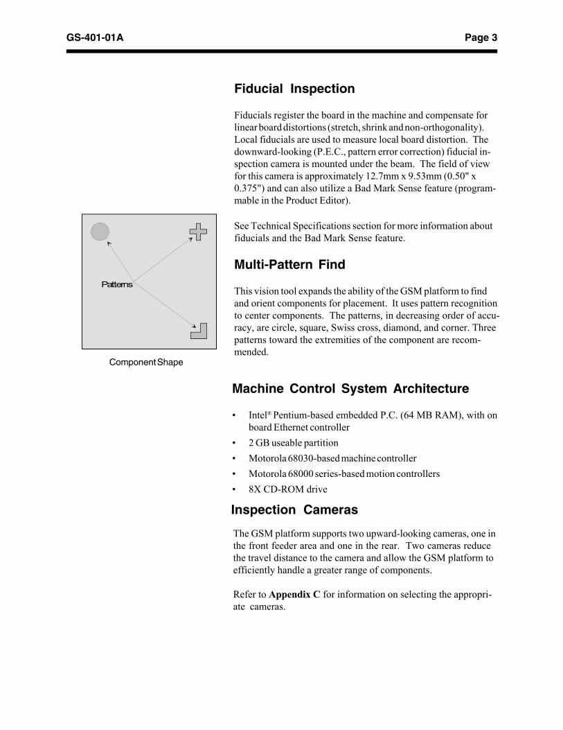
Multi-Pattern Find
This vision tool expands the ability of the GSM platform to findand orient components for placement. It uses pattern recognitionto center components. The patterns, in decreasing order of accu-racy, are circle, square, Swiss cross, diamond, and corner. Threepatterns toward the extremities of the component are recom-mended.

Page 4 GS-401-01A
Universal Platform Software (UPS)
Basic features of Universal Platform Software:• Graphical Windows-style multi-tasking IBM OS/2
operating system.• Configurable user interface with icons and machine
status messages.• Graphical pattern programming tools.• Networkable component and nozzle databases.• User configurable optimization aid.• Comprehensive data import/export.• Powerful query tools.• Programmable feeder templates.• On-the-fly vision inspection, using cutting-edge ESI™
vision engine technology.• Enhanced product set-up, simplifying component and
board programming by teaching images.• Powerful diagnostic and manual axis control tools.• Process management data collection and reporting, to
monitor feeders and nozzles.• On-line documentation for programming, maintenance,
and set-up.
Enhancements to UPS 4.2• Tact time control expands component range.• Mixed heads, with common database for FlexJet and
Flex heads.• Pitch inspection and all-ball count for ball grid array
components.• Management data includes detection and reporting of
pick and vision inspection performance.• Ceramic nozzle support.• Software installation and upgrade improvements.• GSM Platform can measure its own accuracy and
repeatability data and provide statistical informationback through the user interface.
• On-Axis lighting camera support.
UPS offers a Windows-style look and feel for all GSM-based applications. It is a powerful software tool combiningspecific customer requests with previous developments andnumerous software enhancements, as well as new func-tional and operational improvements.

Page 5GS-401-01A
Off-Line PC Requirements
Minimum Recommended
Pentium® -based system Pentium® I I I 500MHz
32 MB RAM 64 MB RAM
200 MB Free HD SpaceWarp 3.0 operat ing system
6.4 GB HD\500 MB Free IBMOS/2 Warp Connect 4.0

Page 6 GS-401-01A
Component Shuttle
Optional FeaturesComponent Shuttle
The shuttle increases total available feeder slots to 116 from thestandard 64 available slots. It provides 64 slots, while using 12slots on the base machine for mounting, for a net gain of 52feeder slots. The component shuttle is installed on the left rearcorner of the base machine.
A second shuttle can be mounted in the front of the GSM plat-form, adding a net of 52 more slots to provide a total of 168 avail-able feeder slots.
In addition to increased feeder capacity, throughput may increaseby providing multiple components for gang-picking by the four-spindle placement head.
Components Used on the Component Shuttle1
All chips, except 0201, 0402 and 0603
All SOT
All SOIC
All SOJ
Up to and including 84 pin PLCC
Tape fed TSOP
Tape fed QFP up to 31.8mm (1.25")
No MELFs1 See Technical Specifications for GSM platform component range.
Gripper Nozzles
Gripper tooling is used for components with no flat surface forvacuum picking. Ribbon cable connectors, inter-board headers,and potting forms are examples of the components handled bythis tooling. The gripping action is accomplished using the samevacuum and air kiss as the standard nozzle tips. An adjustablegripper nozzle is also available to handle various componentwidths. The gripper tooling is compatible with optional nozzlechangers. Each application requires specific tooling.
Contact a Universal Sales Engineer for evaluation of your appli-cation.
Feeders
Feeder options include bulk feeders, tape feeders, track feeders,multi-tube feeders, and matrix tray feeders.
Refer to Appendix A for detailed information.
Gripper Nozzles
Page 7GS-401-01A
Feeder InputNumber of Feeder Slots Used
(Total Available = 64)
Multi-Pitch and Pneumatic 8mm & 12 mm 1 1 slotTape Feeders 16mm, 24 mm, 32mm 1 2 slots
44 mm 1 3 slots56mm 1 4 slots72mm 2 5 slots88mm 2 6 slots104mm 2 6 slots120mm 2 7 slots
Track Feeder 1 3 slots
Multi-Tube Feeder (MTF) 40mm 1 2 slots50mm 1 3 slots
Platform Tray Feeder (PTF) 8 slots
Stackable Matrix Tray 8, 9 or 12 slots
Stationary Matrix Tray Feeder 8 or 9 slots
Odd Form Feeders 2-8 slots
Component Reject Station 3 slots
Coplanarity Test Station 2 slots
Component Shuttle 12 slots1 Can be mounted on the Component Shuttle, component
restrictions apply.2 Not compatible with the Component Shuttle due to a change in pick
point.
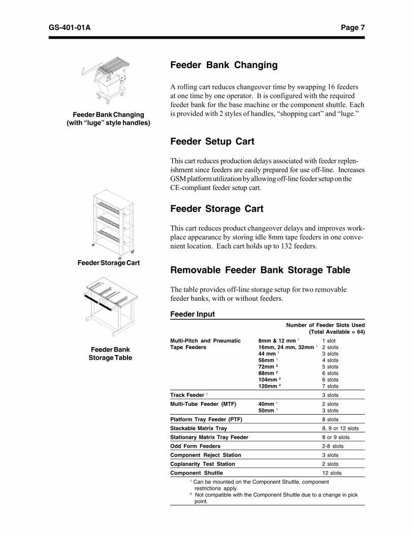
Feeder Storage Cart
Feeder BankStorage Table
Feeder Setup Cart
This cart reduces production delays associated with feeder replen-ishment since feeders are easily prepared for use off-line. IncreasesGSM platform utilization by allowing off-line feeder setup on theCE-compliant feeder setup cart.
Feeder Storage Cart
This cart reduces product changeover delays and improves work-place appearance by storing idle 8mm tape feeders in one conve-nient location. Each cart holds up to 132 feeders.
Removable Feeder Bank Storage Table
The table provides off-line storage setup for two removablefeeder banks, with or without feeders.
Feeder Bank Changing
A rolling cart reduces changeover time by swapping 16 feedersat one time by one operator. It is configured with the requiredfeeder bank for the base machine or the component shuttle. Eachis provided with 2 styles of handles, “shopping cart” and “luge.”Feeder Bank Changing
(with “luge” style handles)

Page 8 GS-401-01A
Dual SMEMA
Universal’s latest board handling software development, DualSMEMA, is designed to enhance dual lane board handling flex-ibility and control. With Dual SMEMA, you can choose theboard handling features that best meet your production needs.
Conveyors transport the board between individual machineswithin a system.
While one board is being populated, another board is bufferedwithin an alternate lane. After a board is populated, processingimmediately begins on the alternate lane’s board. This actionminimizes board transfer time.
See Appendix D for detailed information on Dual Lane BoardHandling.
Board Support
This equipment minimizes the effects of board warp, sag, and/orflex by supporting the board during component placement. Theboard support uses a grid pattern containing removable pins.
Dual Lane Board Handling
Dual Lane BoardHandling
Board Handling
Applied Conveyor Engineering™Conveyors
Ace Conveyors
Page 9GS-401-01A
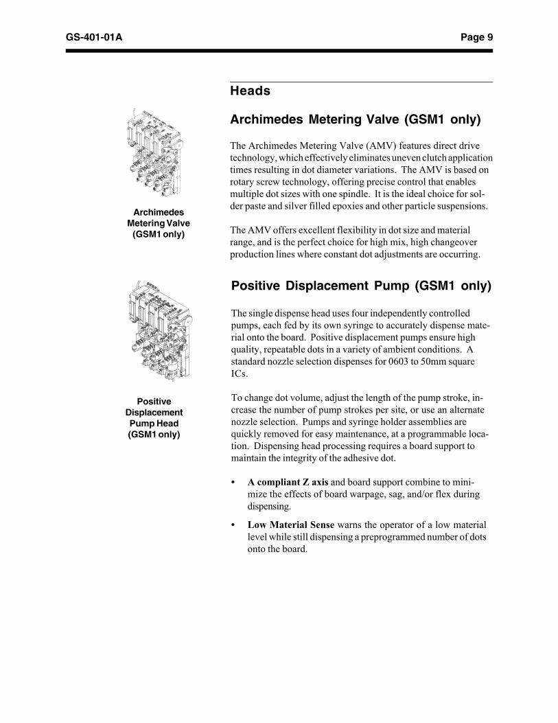
Archimedes Metering Valve (GSM1 only)
The Archimedes Metering Valve (AMV) features direct drivetechnology, which effectively eliminates uneven clutch applicationtimes resulting in dot diameter variations. The AMV is based onrotary screw technology, offering precise control that enablesmultiple dot sizes with one spindle. It is the ideal choice for sol-der paste and silver filled epoxies and other particle suspensions.
The AMV offers excellent flexibility in dot size and materialrange, and is the perfect choice for high mix, high changeoverproduction lines where constant dot adjustments are occurring.
ArchimedesMetering Valve
(GSM1 only)
The single dispense head uses four independently controlledpumps, each fed by its own syringe to accurately dispense mate-rial onto the board. Positive displacement pumps ensure highquality, repeatable dots in a variety of ambient conditions. Astandard nozzle selection dispenses for 0603 to 50mm squareICs.
To change dot volume, adjust the length of the pump stroke, in-crease the number of pump strokes per site, or use an alternatenozzle selection. Pumps and syringe holder assemblies arequickly removed for easy maintenance, at a programmable loca-tion. Dispensing head processing requires a board support tomaintain the integrity of the adhesive dot.
• A compliant Z axis and board support combine to mini-mize the effects of board warpage, sag, and/or flex duringdispensing.
• Low Material Sense warns the operator of a low materiallevel while still dispensing a preprogrammed number of dotsonto the board.
PositiveDisplacementPump Head(GSM1 only)
Positive Displacement Pump (GSM1 only)
Heads

Page 10 GS-401-01A
UFP300+ Head (GSM1 only)
The UFP 300+ Placement Head assembly is the machine’s op-tional ultra-fine pitch placement head. It is a single spindle headcomprised of two major subassemblies: The Theta-Module as-sembly, and the Z-axis assembly. The spindle accepts a varietyof different nozzles, allowing pick-up and transport of variouscomponent sizes and types. It is capable of accurately placingcomponents with up-to or more-than 300 leads and at rotationalincrements as small as 0.001°. The single-spindle UFP (UltraFine Pitch) Head can be mounted to achieve insertion force up to10,000 grams.
UFP300+ Head(GSM1 only)
Flex Head (GSM1 and/or GSM2)
This general purpose 4-spindle head has 40mm spacing betweeneach spindle. It offers added flexibility by placing odd form aswell as most standard surface mount components.
High Force Head (GSM1 and/or GSM2)
The High Force Head assembly is the component pick-up andplacement mechanism, with required enhancements to accommo-date C4 or odd form type components. It is a four spindle headwith each spindle having vertical and rotational movement capa-bility. The spindles are driven in the vertical direction by a singleZ-axis motor (with each spindle individually clutched) for compo-nent pick-up and placement. Each spindle accepts a variety ofdifferent nozzles, allowing pick-up and transport of various com-ponent sizes and types.
FlexJetHead
Flex Head
High Force Head
FlexJet® Head (GSM1 and/or GSM2)
This general purpose 7-spindle head, with 20mm spacing be-tween each spindle and on-the-head camera, handles the broad-est range of surface mount components. It offers the best mixof flexibility and speed for most surface mount applications.

Page 11GS-401-01A
Vision/Inspection
Front and Back Lighting
The GSM platform comes standard with front and back lightingfor component inspection. For front lighting, the inner LEDbanks are strobed as the vision system captures the front imageof the component. For back lighting, the back light towers strobethe two outer LED banks, illuminating the special back lightingnozzle.
The vision system captures the silhouette of the component.Back lighting is recommended for components with highly-reflec-tive component leads, and any component that does not imagewell. It cannot be used with components that require multiplefields of view.
Circular Lighting Camera
This camera provides a 360° low angle lighting scheme for opti-mal illumination of component features, such as PLCC socketleads, BGA bumps, and standard through hole leads. Circularlighting applications should be reviewed by the GSM ApplicationEngineering Group due to the following issues:
• Elimination of component back lighting capability.
• Elimination of 2 feeder slots, 1 on either side of the camera.
Circular LightingCamera
Odd Form Camera
This camera offers vision-assisted placement of odd form andlight electromechanical assembly components. Available in astandard magnification of four mils/pixel, it employs a special“cone” cover. The cone helps direct the light in such a way thatthe ends of the leads of odd form components can be seen. Thecone opening is only 1-1/8" wide.
See Appendix E for detailed information on Odd Form Assem-bly Capabilities.

Page 12 GS-401-01A
On-Axis Lighting Cameras
On-Axis Lighting (OAL) upward-looking cameras build upon thecapabilities of existing front and circular lighting cameras by in-corporating illumination and software specifically designed to en-hance the imaging of highly specular packages, such as CCGAs(Ceramic Column Grid Arrays) and palladium-leaded compo-nents.
From a hardware standpoint, the new OAL cameras provide on-axis illumination to obtain crisp images. From a software stand-point, three (3) enhancements aid in processing CCGA compo-nents:
• Missing Column Inspection: inspects various area-arraypackages for missing columns.
• Pitch Inspection: verifies the distances between componentcolumns or bumps.
• “Sweet Spot” Lighting: provides maximum illumination ofthe component area being inspected.On-Axis Lighting Camera

Page 13GS-401-01A
4 Mil Pass/Fail Criteria
7.8
98.5
0102030405060708090
100
1 2 3 4 5 6
Height of Lead Number 105 in mils
Pro
bab
ility
of
Acc
epta
nce
in
Per
cen
tag
e
#1
#1
#2
#2 #3
#3#4
#4
Detector
Motion
Laser
Coplanarity
The coplanarity assembly is a screening tool for compromisedcomponents, not a metrology tool for component lead measure-ment or incoming inspection.
The coplanarity option measures the deviation of all leads of agiven gull-wing surface mount component, with or withoutbumpers, lying within the same plane. Leads that are coplanarwithin a small tolerance produce fewer defects when massreflow soldered. If a component fails any specified inspection,the component will be rejected into the appropriate reject station.
The laser lead locator (LLL) sensor uses four separate laserbeams to inspect each lead to determine its respective position inthe Z-axis. These positions are used to determine the colinearityand/or the coplanarity of the component leads. The module oc-cupies two feeder positions and is typically installed in the frontleft feeder bank or the rear right feeder bank, adjacent to the up-ward-looking camera station. A front-installed module requires afront-mounted head. Likewise, a rear-installed module requires arear-mounted head.
• The performance model is based on a 208-pin QFP with allleads coplanar except lead number 105, which is set abovethe plane defined by the remaining leads. The model assumes a four mil pass/fail criteria for coplanarity. Varyingthe height of lead number 105 yields the results shown inthe graph.
• This model indicates that components above the pass/failcriteria are rejected with high confidence.
• Verified performance repeatability [(one σ) <0.6 mils] ismeasured utilizing a precision machined 208-pin QFP glassslug.

Page 14 GS-401-01A
Coplanarity Specifications
Component Types 2 & 4 sided gull wing lead configurations withbilateral symmetry and evenly spaced leads
Feeder Slots A coplanarity test station consumes 2 feederslots
Component Size Minimum 3.50mm (0.138")1 + 1/2(tip to tip) nozzle diameter
Maximum 50.8mm (2.00")
Lead Pitch Minimum 0.30mm (0.012")Maximum 1.27mm (0.050")
Lead Width Minimum 0.15mm (0.006")Maximum 0.76mm (0.030")
Lead Count 1 to 250 per side (maximum 1000 leads total)
Lead Length 0.0635mm (0.25") [Minimum for component(body to tip thickness < 4.57mm (0.180")]after form) 2.23mm (0.88") [Minimum for component
thickness > 4.57mm (0.180")]
Foot Length Minimum 0.38mm (0.015")Component Maximum 6.35mm (0.250")Thickness
Coplanarity 1 side up to a 208-pin QFP (52 leads): 0.578Inspection Time seconds(sensor time only) 4 sides up to 208-pin QFP (208 leads): 2.312
seconds
Throughput (12) 208-pin QFPs (2 on the head)(including camera with Coplanarity enabled, no error: 64.00and travel time) seconds
with Coplanarity disabled, no error: 21.23seconds
Scan Inset 0.20mm (0.008") from programmed componenttip to tip dimension
1Components must comply with JEDEC registered outlines. Vision lead inspection tolerance values should be programmed to meet JEDEC tol- erance specifications.

Page 15GS-401-01A
Bar Code Product Changeover
The Bar Code Product Changeover option allows for seamlessproduct changeover without requiring the user to manually loadthe product data or press the start button.
See Appendix F for more information about Bar Code ProductChangeover.
Software Tools
The Generic Equipment Model (GEM) software license providesa set of communication, data collection, command, and controltools for GSM platforms. Based on the Semiconductor Equip-ment and Materials International standard, SEMI E30-93, thissoftware opens the system architecture for integration into fac-tory data collection and automation systems.
Platform Setup Validation (PSV)
This feature ensures correct component-to-feeder slot relation-ship for tape feeders with an integrated bar code validation pro-cess, which provides component level tracking through a historyfile.
See Appendix F for more information on PSV.
Automatic Platform Line Balancer
This off-line software tool automatically or manually balancesproduction time across a line consisting of up to 10 GSM plat-forms, thereby reducing the product build cycle and simplifyingproduct setup processes.
Remote Diagnostics
Remote diagnostics allows Universal support personnel to view aUPS (Universal Platform Software) screen from company head-quarters in Binghamton, New York, USA. This feature providesan enhanced level of technical support and decreases trouble-shooting cycle times for GSM platforms.
GEM

Page 16 GS-401-01A
Transformer
This item allows for the conversion of input power sources to themachine requirements.
Uninterruptible Power Supply
This feature ensures precisely controlled, continuous power to theGSM platform for at least 10 minutes after losing the mainpower.
Electrical/Power Options

Page 17GS-401-01A
Conveyor: Two modes of operation move rejectedcomponents away from the GSM platform placement head:
• Programmable indexing cycles components un- til the sensor is interrupted, stopping the machine.
• The belt moves continuously, moving compo- nents off the end.
Vibratory Reject: Components are moved away from the GSMplatform placement head for manual removal.
Matrix Tray: The stationary matrix tray feeder can beused as a reject matrix for valuable components.
Advanced Surface Mount andSemiconductor Assembly Options
Universal’s GSM platform meets the accuracy requirements nec-essary for the placement of area array components and somesemiconductor assembly applications.
Because these processes often require an advanced level ofcomponent and application process engineering, the hardware/software package of each GSM platform purchased for or up-graded to use in area array and semiconductor applications mustbe evaluated by Universal Instruments.
For more information on GSM platform area array and semicon-ductor assembly capabilities, please consult your Universal SalesEngineer.
Reject Stations
Component Reject Stationfor components up to 50.8mm square:(GSM2 requires 2 stations—front and rear)

Page 18 GS-401-01A
Supporting DocumentsAppendix A GSM Platform FeedersAppendix B Placement HeadsAppendix C CamerasAppendix D Board HandlingAppendix E Odd Form AssembliesAppendix F GSM Platform TraceabilitySMEMA Surface Mount Equipment Manufacturers
Association
Positioning System SpecificationsX Axis Travel 727.46mm (28.640")
Y Axis Travel 1073.15mm (42.250")
Resolution 0.0025mm (0.0001")(2.5 micron scale)

Page 19GS-401-01A
D1
D2
D1
D2
D1
D2
D1
D1
D2
D1
Global and Local Fiducial Shapes and DimensionsShape D1 D2Disc Min=0.762mm (0.030") —
Max=6.35mm (0.250")
Swiss Min=1.02mm (0.040") Min=0.508mm (0.020" )Cross Max=6.35mm (0.250") Max=5.84mm(0.230")
Rectangle Min=0.762mm (0.030") Min=0.762mm (0.030"(Square) Max=6.35mm (0.250") Max=6.35mm (0.250")
Double Min=0.762mm (0.030") Min=1.02mm (0.040" )Box Max=6.35mm (0.250") Max=6.35mm (0.250")Left orRight
Diamond Min=1.27mm (0.050") —Max=4.45mm (0.175")
Plus Min=0.762mm (0.030") Min=0.762mm (0.030")Max=N/A Max=N/A
Recommended Fiducial and Bad Mark SenseUniversal recommends that a minimum of three global fiducials beused for boards assembled on the GSM platform—two to six fiducialsdepending on the process. Although the GSM platform handles arange of fiducial types, the most reliable fiducial recommendationsfollow:
Shape Disc (solid, filled circle)
Size Minimum -- 1.00mm (0.040")Maximum -- 3.00mm (0.118")
Tolerance 0.025mm (0.001")
Clearance The fiducial clearance area must be at least twotimes the diameter of the fiducial
Material Bare copper or copper covered with either clearanti-oxidation coating, nickel plating, tin plating,or hot air leveled solder coating.
Flatness The fiducial surface should be flat within0.015mm (0.0006" )
Mask Solder resist coatings should not cover a fiducialmark or its clearance area.

Page 20 GS-401-01A
Board SpecificationsMinimum Maximum1
Length 50.8mm (2.00") 584.2mm (23.00")
Width 50.8mm (2.00")2 508.0mm (20.00")3
Thickness 0.508mm (0.020") 5.08mm (0.200")
Weight — 2.72 kg (6 pounds)4
Allowable Warp For board transfer: 5.537mm (0.218") minusboard thickness
For placement: 0.75% of board length(as per IPC-2221), notto exceed 3.175mm(0.125") total
1 The GSM platform has populated boards up to 25" x 20". Consult aUniversal Sales Engineer for details.
2 The component reject bin must be relocated and mechanical board stopsmust be removed.
Board ClearanceTop Side Clearance 12.7mm (0.500")
3 A maximum board width of 457.2mm (18.00") includes nozzle changersmounted between the rear feeder plate and the staged board handlingsystem.
4 Represents the sum of all board weights within the GSM platform boardhandling system.
Note: For other sizes, consult a Universal Sales Engineer
Bottom Side See illustrationClearance
Board HandlingMinimum Maximum
Transfer Height 899mm (35.4") 965.2mm (38.00")
Transfer Time 0.0 sec1 2.5 sec2
1 With Staged Board Handling.2 With Dual Lane Board Handling.
25.4mm (1.0")
12.7mm (0.5")clearance underboard
Fixed front railRear rail P.C. boardsection
P.C. boardrails
component
com
pone
nt
25.4mm (1.0")clearance underboard Edge Clearance Standard: 5mm (0.195"), ±0.4mm (0.02")
toleranceOptional: 3mm (0.117"), ±0.4mm (0.02")tolerance
Rear Rail Position LocationThere are currently two mounting positions for the rear feeder baseplate on a GSM1 and three on the GSM2 to optimize throughput.
• The outbound position maximizes board width at 457mm (18").
• The inbound position mounts the rear feeder base plate closer tothe center of the GSM1. This position reduces the board widthallowed, and also the head travel between the feeder pick pointsand the circuit board being populated. Reduced travel optimizesdistance and time, increasing throughput.
Rear Feeder Bank Position Maximum Board Width
Outbound 457mm (18.00")
127mm (5") inbound 330mm (13.00")
216mm (8.5") inbound 305mm (12.00") (GSM2 only)
Page 21GS-401-01A
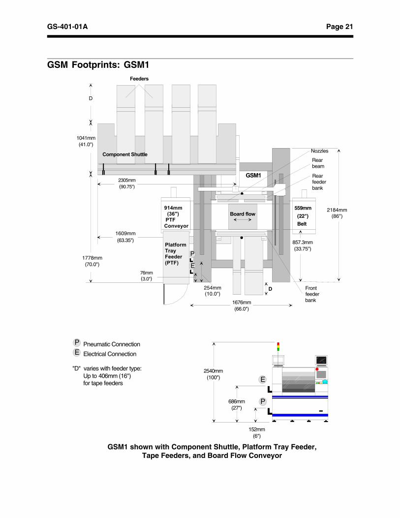
GSM1 shown with Component Shuttle, Platform Tray Feeder,Tape Feeders, and Board Flow Conveyor
GSM Footprints: GSM1
D
Board flow
GSM1
559mm
(22")
Belt
1676mm(66.0")
P
E
857.3mm(33.75")
254mm(10.0")
Rear beam
Rear feeder bank
Front feeder bank
Nozzles
Pneumatic Connection
Electrical Connection
"D" varies with feeder type: Up to 406mm (16") for tape feeders
PE
686mm(27")
152mm(6")
2540mm(100")
P
E
(70.0")
1041mm(41.0")
D
Feeders
(63.35")
2305mm(90.75")
Component Shuttle
914mm (36") PTFConveyor
PlatformTray Feeder(PTF)
76mm(3.0")
1778mm
1609mm
2184mm(86")

Page 22 GS-401-01A
GSM2 shown with Component Shuttle, Platform Tray Feeder,Tape Feeders, and Board Flow Conveyor
D
Board flow
GSM2
559mm
(22")
Belt
1676mm(66.0")
P
E
857.3mm(33.75")
254mm(10.0")
Rear beam
Front beam
Rear feeder bank
Front feeder bank
Nozzles
914mm(36") PTFConveyor
PlatformTray Feeder(PTF)
76mm(3.0")
1778mm(70.0")
1041mm(41.0")
D
Feeders
1609mm(63.35")
2305mm(90.75")
Component Shuttle
2540mm (100")
Pneumatic Connection
Electrical Connection
"D" varies with feeder type: Up to 406mm (16") for tape feeders
PE
686mm(27")
152mm(6")
P
E
(Beam 1)
(Beam 2)
2184mm (86")
GSM Footprints: GSM2
Page 23GS-401-01A
Installation Considerations
Machine Dimensions: GSM1Length1 Depth Height 2 Weight
GSM1 Base 1676mm 2184mm 2540mm 2614kgMachine (66") (86") (100") (5762 lbs)
Domestic 1905mm 2591mm 1854mm 2772kgShipping (75") (102") (73") (6112 lbs)
Air Freight 1930mm 2616mm 1854mm 2986kg(76") (103") (73") (6582 lbs)
Sea Freight 1930mm 2616mm 1854mm 3056kg(76") (103") (73") (6738 lbs)
Component 2305mm 1041mm 1473mm 953 kgShuttle (90") (41") (58") (2100 lbs)
Air Freight 2767mm 1245mm 1803mm 1112 kg(109") (49") (71") (2450 lbs)
Sea Freight 2767mm 1245mm 1803mm 1112 kg(109") (49") (71") (2450 lbs)
Floor Space A minimum clear area of one meter (three feet)around the machine perimeter is recommended formachine operation and servicing.
1 Length is in the direction of board flow.2 Machine light tower and monitor shipped separately.
Machine Dimensions: GSM2Length1 Depth Height 2 Weight
GSM2 Base 1676mm 2184mm 2540mm 2795kgMachine (66") (86") (100") (6162 lbs)
Domestic 1905mm 2591mm 1854mm 2954kgShipping (75") (102") (73") (6512 lbs)
Air Freight 1930mm 2616mm 1854mm 3167kg(76") (103") (73") (6982 lbs)
Sea Freight 1930mm 2616mm 1854mm 3238kg(76") (103") (73") (7138 lbs)
Component 2305mm 1041mm 1473mm 953 kgShuttle (90") (41") (58") (2100 lbs)
Air Freight 2767mm 1245mm 1803mm 1112 kg(109") (49") (71") (2450 lbs)
Sea Freight 2767mm 1245mm 1803mm 1112 kg(109") (49") (71") (2450 lbs)
Floor Space A minimum clear area of one meter (three feet)around the machine perimeter is recommended formachine operation and servicing.
1 Length is in the direction of board flow.2 Machine light tower and monitor shipped separately.
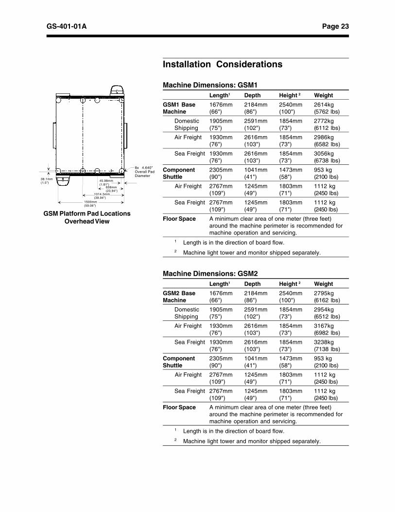
GSM Platform Pad LocationsOverhead View
8x 4.640"Overall Pad Diameter
45.98mm(1.81")
38.1mm(1.5")
608mm(23.94")
1014.5mm(39.94")
1500mm(59.06")
Page 24 GS-401-01A
Service RequirementsElectrical 230 VAC, nominal
Frequency 50 or 60 Hz (49-51 or 59-61 Hz).Frequency must be stated at time of order.
Phases 3
Number of 4 (three phase lines and ground)Wires
Service Service must be grounded DeltaConfiguration
Branch Circuit 30 ampsSize
Distortion <10% total harmonic distortion
Average Power 5000 watts
Electrical 76.2mm (3") from frontConnection 686mm (27") from floor
Pneumatics (clean air)
Air flow requiredto base machine1
GSM1 212.4 liters/minute @6.21 bar (7.5 cfm @90psi)GSM2 424.8 liters/minute @6.21 bar (15.0 cfm @90psi)
Clean Air Clean air is defined as: dew point must be 20°F.(11°C.) below ambient temperature; oil at0.08ppm at 82°F. (28°C.); input air filtered to 5microns particle size.
Pneumatic 254mm (10") from front,152.4mm (6") from floor.Connection Internal thread connenection is 9.65mm (3/8")
NPT and provided with the machine.Equipment is adequately protected againstingress of solid and liquid contaminants.
1 Air flow value is used to calculate the input air line which mightsupply several machines. The flow value is measured in litersper minute (liters/min) or cubic feet per minute (cfm).
Environmental RequirementsMinimum Maximum
Operating 4.4° C (40° F) 35° C (95° F)Temperature
Operating — 6° C/hourTemperature (10.8° F/hour)Change Tolerance
Storage -20° C (-4° F ) 65° C (149° F)Temperature
Operating Humidity 10% non-condensing 90% non-condensing
Operating Altitude — 2500 meters (8202 feet)
Noise level 70.5 dbA in accordance with National MachineToolbuilders Assoc. Noise MeasurementTechnique Standard — June 1986.

A - 25Appendix A: GSM Platform Feeders - GS-401-01A
Appendix A: GSM Platform Feeders
Platform Tray Feeder (PTF), Model 4559A
Introduction
Universal’s optional Platform Tray Feeder (PTF), Model 4559A,is a 58-input stackable matrix tray feeder for GSM platforms,which increases flexibility, improves line performance, and maxi-mizes throughput.
The PTF is flexible. It features 29 pallets, each configurable withup to two unique component types. Up to 58 different leaded andarea-array components can be fed to the GSM platform. If de-sired, one of the pallets can be defined for component purge orreject, reducing usable pallets to 28 x 56 inputs. While a singlePTF provides all these benefits, a second PTF expands flexibilityeven further. Beyond the additional 58 inputs gained from a sec-ond PTF, dual PTFs provide several modes of operation to matchproduction requirements.
The PTF is efficient. Rather than just one matrix tray at a time,the PTF can support stacks of matrix trays. This capability sig-nificantly reduces tray replenishment requirements and increasesthroughput. And, the unique side-mounting scheme of the PTFmaximizes floor space utilization without interfering with adjacentproduction lines. The PTF may be optionally configured topresent components at rotations of 0°, 90°, 180°, or 270° for pickby the GSM platform to increase machine throughput.
The PTF is fast. While many other matrix tray feeders wastetime by presenting the entire tray or just a couple of componentsto the pick and place head, the PTF can present up to 7 compo-nents to the GSM head. The independent PTF pick and placeaxes buffer components for the next cycle in the GSM platform.In parallel, the GSM platform gang picks components (simulta-neously picks multiple components) previously queued on thePTF transfer belt. The PTF features user programmable servo-controlled pallet and transfer belt motions to provide optimal com-ponent handling speed.
In consideration of essential health and safety requirements, thePTF is CE-marked.
Transfer Shuttleto GSM
Door to accesselevator and refillpallets with matrixtrays
Platform Tray Feeder (PTF)
PTF
PTF transfer shuttle
GSM

A - 26 GS-401-01A - Appendix A: GSM Platform Feeders
Functional Description
The primary function of the PTF is to provide components frommatrix trays for gang picking by the GSM platform. To accom-plish this, the component and matrix trays are defined using thefeeder and component databases in the Product Editor duringsetup.
There are 3 modes of operation applicable to dual PTFs:
Independent Mode allows the two PTFs configured on aGSM platform to act as two unique matrix tray feeders.This configuration provides 116 matrix tray inputs. For ex-ample Components 1-58 are fed by one PTF and Compo-nents 59-116 are fed by the second PTF. In this mode,neither PTFcan act as an alternate to the other; however,a GSM platform-mounted feeder can be an alternatefeeder to either PTF.
Backup Mode allows the two PTFs configured on a GSMplatform to serve as backup feeders to each other. Thebackup PTF will not deliver components unless the primaryPTF is out of a specific component or the primary PTF isin the load feeder state. Once the primary PTF is reloaded,the component will be accessed by the primary PTF. Forexample, Component A is depleted from the primary PTF,so the backup PTF supplies Component A until the primaryPTF is reloaded. Both primary and backup PTFs must beaccessible by the same beam. As with the IndependentMode, a GSM platform-mounted feeder can act as an al-ternate PTF feeder. The goal is to produce boards asquickly as possible, based on component availability. Thebackup PTF will maximize throughput.
Exchange Mode allows the two PTFs configured on aGSM platform to act as alternate feeders. In this mode,the primary and secondary PTFs switch when a singlecomponent is no longer available in the primary PTF. Forexample, once Component A is depleted in the PrimaryPTF, all components will be picked from the alternate PTF.Component A will continue to be picked from the alternatePTF until Component A is no longer available, then allcomponents will once again be picked from the primaryPTF. Both PTFs must be accessible by the same beam.This mode is suggested when the primary and secondaryPTF magazines are balanced.
Platform Tray Feeder (PTF)(reverse view)
A - 27Appendix A: GSM Platform Feeders - GS-401-01A
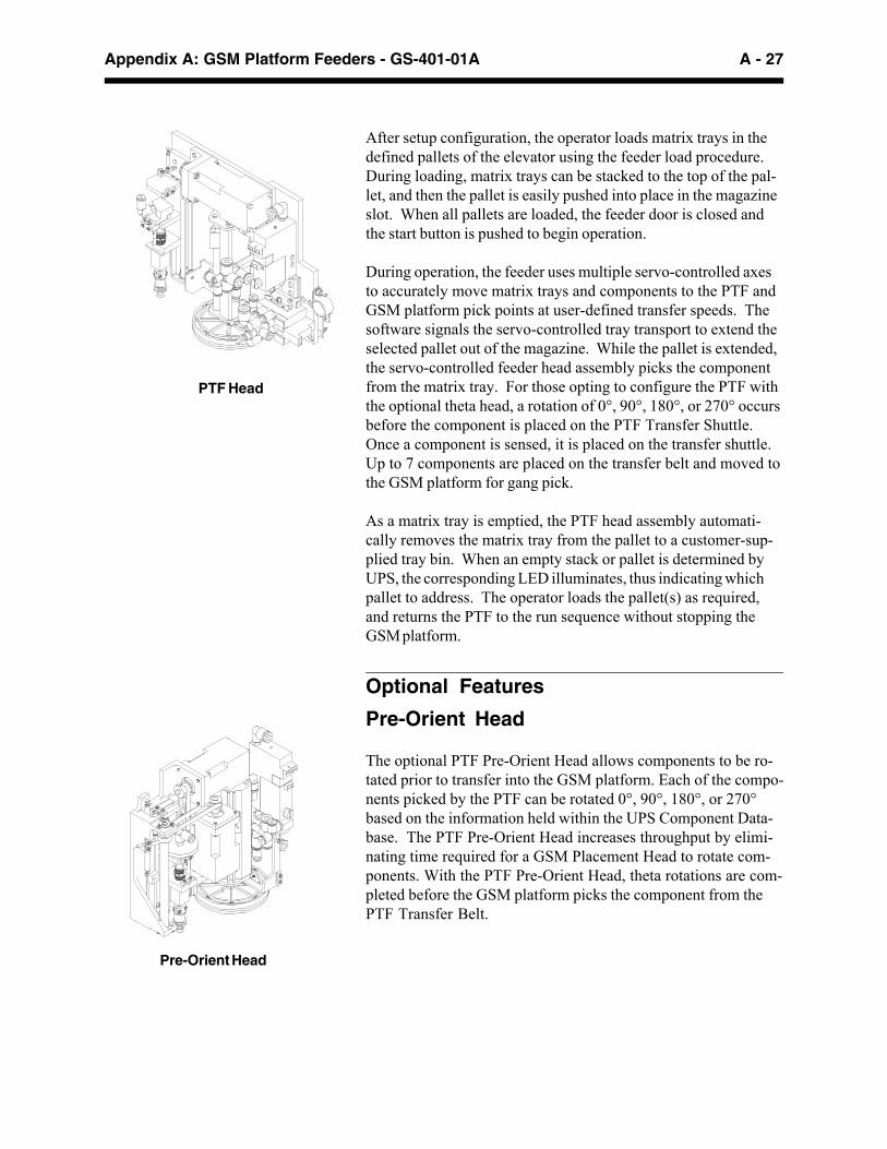
After setup configuration, the operator loads matrix trays in thedefined pallets of the elevator using the feeder load procedure.During loading, matrix trays can be stacked to the top of the pal-let, and then the pallet is easily pushed into place in the magazineslot. When all pallets are loaded, the feeder door is closed andthe start button is pushed to begin operation.
During operation, the feeder uses multiple servo-controlled axesto accurately move matrix trays and components to the PTF andGSM platform pick points at user-defined transfer speeds. Thesoftware signals the servo-controlled tray transport to extend theselected pallet out of the magazine. While the pallet is extended,the servo-controlled feeder head assembly picks the componentfrom the matrix tray. For those opting to configure the PTF withthe optional theta head, a rotation of 0°, 90°, 180°, or 270° occursbefore the component is placed on the PTF Transfer Shuttle.Once a component is sensed, it is placed on the transfer shuttle.Up to 7 components are placed on the transfer belt and moved tothe GSM platform for gang pick.
As a matrix tray is emptied, the PTF head assembly automati-cally removes the matrix tray from the pallet to a customer-sup-plied tray bin. When an empty stack or pallet is determined byUPS, the corresponding LED illuminates, thus indicating whichpallet to address. The operator loads the pallet(s) as required,and returns the PTF to the run sequence without stopping theGSM platform.
Optional Features
Pre-Orient Head
The optional PTF Pre-Orient Head allows components to be ro-tated prior to transfer into the GSM platform. Each of the compo-nents picked by the PTF can be rotated 0°, 90°, 180°, or 270°based on the information held within the UPS Component Data-base. The PTF Pre-Orient Head increases throughput by elimi-nating time required for a GSM Placement Head to rotate com-ponents. With the PTF Pre-Orient Head, theta rotations are com-pleted before the GSM platform picks the component from thePTF Transfer Belt.
Pre-Orient Head
PTF Head

A - 28 GS-401-01A - Appendix A: GSM Platform Feeders
Configurations
PTF
RearRight
PTF
FrontLeft
PTF
FrontRight
PTF
FrontLeft
PTF
RearLeft
PTF
FrontRight
PTF
RearRight
PTF
RearLeft
FrontFront
FrontGSM1 only
FrontGSM1 only
Rear Rear
Rear Rear
Single PTF can bemounted as such:
Dual PTFs can bemounted as such:
Front Right (GSM1 only) Front Right and Front Left(GSM1 only)
Front Left Front Right and Rear Left(GSM1 only)
Rear Left Rear Right and Rear Left
Rear Right Front Left and Rear Right
A - 29Appendix A: GSM Platform Feeders - GS-401-01A
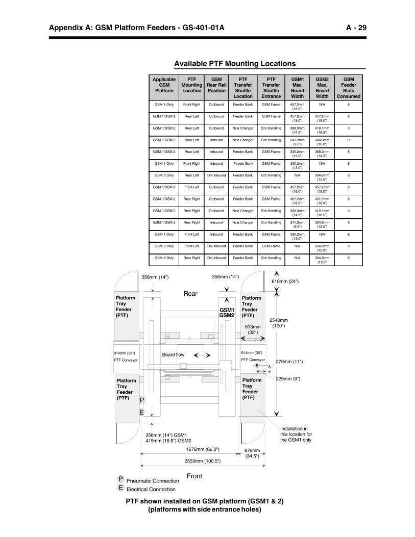
PTF shown installed on GSM platform (GSM1 & 2)(platforms with side entrance holes)
Rear
Front
Available PTF Mounting Locations
GSM1
914mm (36")
PTF Conveyor
914mm (36")
PTF ConveyorBoard flow
P
E
Pneumatic Connection
Electrical Connection
PE
PlatformTray Feeder(PTF)
PlatformTray Feeder(PTF)
PlatformTray Feeder(PTF)
PlatformTray Feeder(PTF)
1676mm (66.0")
813mm (32")
356mm (14") GSM1419mm (16.5") GSM2
E
356mm (14") 356mm (14")
2540mm (100")
279mm (11")
610mm (24")
229mm (9")
876mm (34.5")
2553mm (100.5")
Installation in this location for the GSM1 only
GSM2
ApplicableGSM
Platform
PTFMountingLocation
GSMRear RailPosition
PTFTransferShuttle
Location
PTFTransferShuttle
Entrance
GSM1Max.
BoardWidth
GSM2Max.
BoardWidth
GSMFeederSlots
Consumed
GSM 1 Only Front Right Outbound Feeder Bank GSM Frame 457.2mm(18.0")
N/A 8
GSM 1/GSM 2 Rear Left Outbound Feeder Bank GSM Frame 457.2mm(18.0")
457.2mm(18.0")
8
GSM 1/GSM 2 Rear Left Outbound Nzle Changer Brd Handling 368.3mm(14.5")
419.1mm(16.5")
0
GSM 1/GSM 2 Rear Left Inbound Nzle Changer Brd Handling 241.3mm(9.5")
304.8mm(12.0")
0
GSM 1/GSM 2 Rear Left Inbound Feeder Bank GSM Frame 330.2mm(13.0")
368.3mm(14.5")
8
GSM 1 Only Front Right Inbound Feeder Bank GSM Frame 330.2mm(13.0")
N/A 8
GSM 2 Only Rear Left Dbl Inbound Feeder Bank Brd Handling N/A 304.8mm(12.0")
8
GSM 1/GSM 2 Front Left Outbound Feeder Bank GSM Frame 457.2mm(18.0")
457.2mm(18.0")
8
GSM 1/GSM 2 Rear Right Outbound Feeder Bank GSM Frame 457.2mm(18.0")
457.2mm(18.0")
8
GSM 1/GSM 2 Rear Right Outbound Nzle Changer Brd Handling 368.3mm(14.5")
419.1mm(16.5")
0
GSM 1/GSM 2 Rear Right Inbound Nzle Changer Brd Handling 241.3mm(9.5")
304.8mm(12.0")
0
GSM 1 Only Front Left Inbound Feeder Bank GSM Frame 330.2mm(13.0")
N/A 8
GSM 2 Only Front Left Dbl Inbound Feeder Bank GSM Frame N/A 304.8mm(12.0")
8
GSM 2 Only Rear Right Dbl Inbound Feeder Bank Brd Handling N/A 304.8mm(12.0"
8
A - 30 GS-401-01A - Appendix A: GSM Platform Feeders
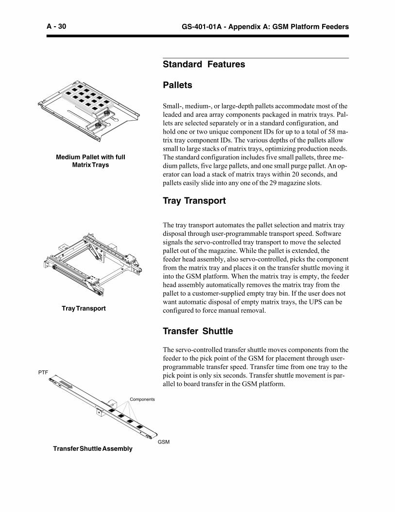
The tray transport automates the pallet selection and matrix traydisposal through user-programmable transport speed. Softwaresignals the servo-controlled tray transport to move the selectedpallet out of the magazine. While the pallet is extended, thefeeder head assembly, also servo-controlled, picks the componentfrom the matrix tray and places it on the transfer shuttle moving itinto the GSM platform. When the matrix tray is empty, the feederhead assembly automatically removes the matrix tray from thepallet to a customer-supplied empty tray bin. If the user does notwant automatic disposal of empty matrix trays, the UPS can beconfigured to force manual removal.
Pallets
Small-, medium-, or large-depth pallets accommodate most of theleaded and area array components packaged in matrix trays. Pal-lets are selected separately or in a standard configuration, andhold one or two unique component IDs for up to a total of 58 ma-trix tray component IDs. The various depths of the pallets allowsmall to large stacks of matrix trays, optimizing production needs.The standard configuration includes five small pallets, three me-dium pallets, five large pallets, and one small purge pallet. An op-erator can load a stack of matrix trays within 20 seconds, andpallets easily slide into any one of the 29 magazine slots.
Tray Transport
Transfer Shuttle
The servo-controlled transfer shuttle moves components from thefeeder to the pick point of the GSM for placement through user-programmable transfer speed. Transfer time from one tray to thepick point is only six seconds. Transfer shuttle movement is par-allel to board transfer in the GSM platform.
Tray Transport
Transfer Shuttle Assembly
Medium Pallet with fullMatrix Trays
GSM
PTF
Components
Standard Features

A - 31Appendix A: GSM Platform Feeders - GS-401-01A
Technical Specifications
ConfigurationGSM Software The PTF is controlled by Universal Platform
Software (UPS). The UPS processes diagnosticmessages, and optimization of one product.Included is a graphic interface for definingcomponents, matrix trays, magazine slots andfeeder configuration from the feeder andcomponent database.
Configuration The base platform has side entrance holes forinstalling the PTF transfer shuttle in the rightrear, left rear, and left front. The right frontinstallation is supported on the GSM1 only. ThePTF transfer shuttle can be mounted in otherlocations. Consult a Universal SalesEngineer.
A manual slide-width 914mm (36") PTFConveyor is supplied with the PTF.
Required 8 slots when installed in side entranceSlots holes.
Empty Tray Bin Use to collect empty matrix trays, customersupplied.
Component Pick and Transfer SpecificationsTact Time1 1.5 seconds per component
Transfer Time1 4 components from one tray: 6.25 seconds4 components from 4 adjacent pallets: 9 seconds
Shuttle Transfer 899mm to 965.2mm (35.4" to 38.00")Height1 Based on average moves across an entire matrix tray over variouspallet types.
Suggested configurationsfor a PTF installation on the
feeder bank of the GSM
Platform front
36" PTFConveyor
Board flow
PTF TransferShuttle
æ
GSM
Feeders
Platform front
Boardflow
PTF GSM
36" PTFConveyor
TransferShuttle
Feeders
æ
Platform front
22"Conveyor
Board flow
PTFæ
GSM
36" PTFConveyor
TransferShuttle
Feeders

A - 32 GS-401-01A - Appendix A: GSM Platform Feeders
ComponentsType Leaded and area array
Dimensions 6.4mm to 51mm (0.25" to 2.0") square, manualnozzle change may be required for a full rangeof component picking.
Thickness 1.0mm to 12.7mm (0.04" to 0.50"), flat andsmooth surface for vacuum retention.
Weight Up to 35 grams each.1
1 Heavier components up to 50 grams can be handled when pre-orient isdisabled.
Matrix TrayDimensions • 102mm x 102mm x 3mm (4" x 4" x 0.1"),
minimum• 330mm x 292mm x 12.7mm (13.0" x 11.5" x
0.5"), one component ID, or• 330mm x 140mm x 12.7mm (13.0" x 5.5" x
0.5") for one or two component IDs (twomatrix trays) in one pallet.
Height Height of trays and components cannot exceedthe top of the pallet.
Weight (Maximum) 300 grams maximum empty weight. Trays thatdo not meet IEC 286 standards can be manuallyremoved.
Pick Area, Empty Tray vacuum pick-up method requires aminimum-walled pick up area that allowsvacuum retention and therefore removal of anempty matrix tray. Reference IEC specificationsfor requirements. [Based on IEC specification,minimum 28mm x 28mm (1.1" x 1.1") walled-offarea. IEC specification does not specify amaximum walled-off. Platform Tray FeederREQUIRES a maximum 45mm x 70mm (1.75" x2.75") walled-off area.]*
*An optional tray removal kit, for larger pocket areas up to 50mm x88mm (2.00" x 3.50") walled-off area, is available.

A - 33Appendix A: GSM Platform Feeders - GS-401-01A
PalletsSmall Medium Large
(Type 1) (Type 2) (Type 4)
Pallet Depth 12.7mm (0.50") 26.7mm (1.05") 64.8mm (2.55")
Pallet Capacity
Number of stacks 1 or 2 1 or 2 1 or 2
Number of trays 2 4 10per stack1
Magazine slots 1 2 4required per pallet
Load Time 20 to 30 seconds to load a stack of trays andclamp each stack flush with the palletleading edge.
Pallet Weight (Full) 7.26 kg (16 lbs.), maximum combinedweight of pallet and full matrix trays.
Pallet Weight (Empty) Large 3.18 kg (7 lbs.)Medium 2.61 kg (5.75 lbs.)Small 2.18 kg (4.8 lbs.)Purge 2.18 kg. (4.8 lbs.)
1 Based on IEC thin tray specification of 6.35mm (0.25"). If thicker traysare used, the stack height will be less. Stack height cannot exceed thetop of the pallet (including components). See “Pallet Depth,” above.
MagazineMagazine Capacity 29 pallet slots
Standard magazine package includes 5small, 3 medium, and 5 large pallets, plusone purge pallet. A large pallet is placed inthe bottom magazine slot to accommodatethis pallet mix.
Capacity 61.3 kg (135 pounds), including pallets,matrix trays, and components. See examplebelow:
Loaded Elevator Example — Standard Pallet Configuration
5 large (type 4) pallets x 3.18 kg (7 lbs.) = 15.88 kg (35 lbs.)3 medium (type 2) pallets x 2.61 kg (5.75 lbs.) = 7.82 kg (17.25 lbs.)
5 small (type 1) pallets x 2.18 kg (4.8 lbs.) = 10.89 kg (24 lbs.)1 purge pallet x 2.18 kg (4.8 lbs.) = 2.18 kg (4.8 lbs.)
Total = 36.74 kg (81 lbs.)
Total Weight (incl. pallets, parts, and trays) = 61.23 kg (135 lbs.)– Standard Pallet Configuration = 36.74 kg (81 lbs.)
Component/Tray Weight = 24.49 kg (54 lbs.)
Optional Payload Kit
2 magazine slots
Full matrix traysPartially full matrix trays
Medium size pallet
Component ID #1 Component ID #2
1 magazine slot
Small size pallet
Partially full matrix trays
Component ID #2 Component ID #1
4 magazine slots
Full matrix traysPartially full matrix trays
Large size pallet
Full matrix traysFull matrix trays
Component ID #1 Component ID #2
Total Weight (incl. pallets, parts, and trays) = 90.70 kg (200 lbs.)– Standard Pallet Configuration = 36.74 kg (81 lbs.)
Component/Tray Weight = 53.96 kg (119 lbs.)

A - 34 GS-401-01A - Appendix A: GSM Platform Feeders
Installation ConsiderationsLength 1 Depth Height Weight
Overall 813mm 1524mm 1575mm 524 kg(32") (60") (62") (1155 lbs.)
Domestic 1067mm 1753mm 1702mm 568 kgShipping (42") (69") (67") (1250 lbs.)
Air Freight 1092mm 1753mm 1753mm 615 kg(43") (69") (69") (1355 lbs.)
Sea Freight 1092mm 1753mm 1753mm 624 kg(43") (69") (69") (1375 lbs.)
Floor Space A minimum clear area of one meter (three feet)around the machine perimeter is recommended formachine operation and servicing.
1 Length is in the direction of board flow.
PTF Service RequirementsElectrical 230 VAC, provided by the GSM platform
250 Watts RMS400 Watts PeakElectrical interface is needed for existing GSMplatform installations. Consult a UniversalSales Engineer.
Pneumatic Provided by the GSM platform
Air Flow 17 liters/[email protected] bar (0.6 cfm@90 psi)
Vacuum Generated internally by PTF feeder
PTF Conveyor Service Requirements100 to 130 VAC, 50/60 Hz, 5 amperes200 to 260 VAC, 50/60 Hz, 5 amperes.Separate drop required.
Environmental RequirementsMinimum Maximum
Operating 4.4° C (40° F) 35° C (95° F)Temperature
Operating — 6° C/hourTemperature (10.8° F/hour)Change Tolerance
Storage -20° C (-4° F) 65° C (149° F)Temperature
Operating Humidity 10% non-condensing 90% non-condensing
Operating Altitude — 2500 meters (8202 feet)
Noise 70 dbA in accordance with National Machine

A - 35Appendix A: GSM Platform Feeders - GS-401-01A
Supporting Documents
International Electrotechnical Commission (IEC) Standards,286-5, revision 1995-02 for Packaging of Components forAutomatic Handling
SMEMA Software/Communications Interface Standard 2.0
A - 36 GS-401-01A - Appendix A: GSM Platform Feeders
Stackable Matrix Tray Feeder
Stackable Matrix Tray Feeder, Model 4556A
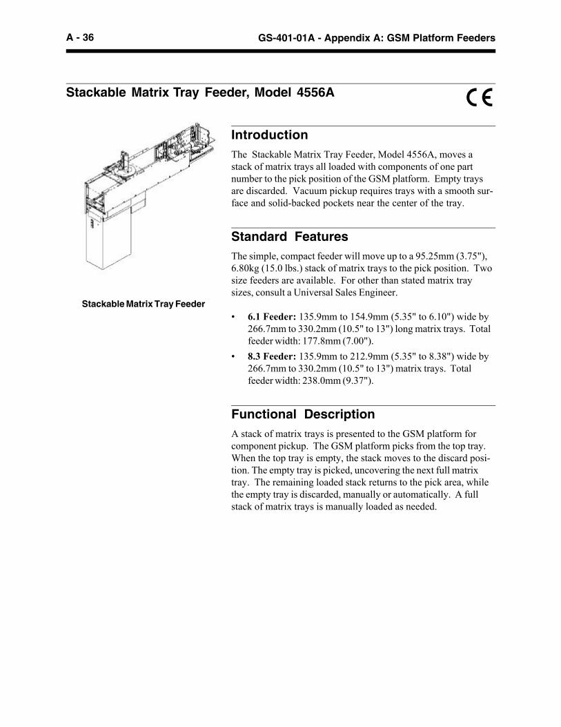
IntroductionThe Stackable Matrix Tray Feeder, Model 4556A, moves astack of matrix trays all loaded with components of one partnumber to the pick position of the GSM platform. Empty traysare discarded. Vacuum pickup requires trays with a smooth sur-face and solid-backed pockets near the center of the tray.
Standard FeaturesThe simple, compact feeder will move up to a 95.25mm (3.75"),6.80kg (15.0 lbs.) stack of matrix trays to the pick position. Twosize feeders are available. For other than stated matrix traysizes, consult a Universal Sales Engineer.
• 6.1 Feeder: 135.9mm to 154.9mm (5.35" to 6.10") wide by266.7mm to 330.2mm (10.5" to 13") long matrix trays. Totalfeeder width: 177.8mm (7.00").
• 8.3 Feeder: 135.9mm to 212.9mm (5.35" to 8.38") wide by266.7mm to 330.2mm (10.5" to 13") matrix trays. Totalfeeder width: 238.0mm (9.37").
Functional DescriptionA stack of matrix trays is presented to the GSM platform forcomponent pickup. The GSM platform picks from the top tray.When the top tray is empty, the stack moves to the discard posi-tion. The empty tray is picked, uncovering the next full matrixtray. The remaining loaded stack returns to the pick area, whilethe empty tray is discarded, manually or automatically. A fullstack of matrix trays is manually loaded as needed.

A - 37Appendix A: GSM Platform Feeders - GS-401-01A
Technical SpecificationsLength Width Height Weight
Overall 930mm 177.8mm- 800.2mm 22.7kg(36.62") 238.0mm (31.50") (50 lbs.)
(7"-9.37")
Elevator N/A N/A 412.8mm 15.9kg(16.25") (35 lbs.)
Electrical N/A N/A 387.4mm 6.8kgEnclosure (15.25") (15 lbs.)Assembly
Floor Clearance 356.6mm (14"), approximately
Altitude Up to 1000m above mean sea level
Ambient Air +5°C to +40°CTemperature Range
Average Ambient Not to exceed +35°C in 24 hours.Air TemperatureRange
Free Air Operating +5°C to +55°CTemperature
Average Free Air Not to exceed +50°C in 24 hours.OperatingTemperature
Humidity Range 30% to 95%, non-condensing.
Noise 65 dbA
Transportation -25°C to +55°C., up to +70°C. in 24 hoursand Storage Store in shipping carton, Universal # M00067900
or mounted on Feeder Cart Assembly,Universal # 45577701.
Required Feeder 6.1 Feeder: 9 feeder slotsPositions 8.3 Feeder: 12 feeder slots
Service Requirements
Electrical Power is provided by the Universal Platform.IEC-type connector, 120VAC, 50-60 Hz.,1.6 ampere. Voltage fluctuation, 10%.
Pneumatic Air is provided by the Universal Platform at84.95 liters/minute at 5.52 bar (3 cfm at 80 psi)with a 6.35mm (0.25") hose.
Vacuum Generated internal to the feeder.
Safety Bottom panel provided.
Moving 27.22 kgs (60 lbs.) pallet jack, and 15 minutes touncrate. To lift uncrated Feeder, disassembleand use lift points shown in illustration.

A - 38 GS-401-01A - Appendix A: GSM Platform Feeders
32mmEmbossed Carrier
16mmCarrier Tape
32mm Feeder
Multi-Pitch Tape Feeders, Model 4697A
Introduction
The Multi-Pitch Tape Feeder, Model 4697A, is available to pro-cess a wide range of embossed component tapes. Reel loaderfeeders can be kept ready for installation on the GSM platform.
Machine Concept
Each feeder is dedicated to a tape width with adjustable pitch se-lections, depending on desired tape pitch. The tape advancementis stepper motor driven, capable of forward and reverse tape ad-vancement control. Electrical connections are engaged when thefeeder is mounted to the GSM platform.
Standard Features
Feeder units are adjustable for pitch settings from 4mm - 44mm.Select a dedicated multi-pitch tape feeder based on tape width.
• 8mm (2mm - 8mm pitch)1
• 12mm (4mm - 12mm pitch)1
• 16mm (4mm - 20mm pitch)
• 24mm (4mm - 28mm pitch)
• 32mm (4mm - 36mm pitch)
• 44mm (4mm - 44mm pitch)
• 56mm (4mm - 44mm pitch)2
• 72mm (4mm - 44mm pitch)2
• 88mm (4mm - 44mm pitch)2
• 104mm (4mm - 44mm pitch)2
• 120mm (4mm - 44mm pitch)2
1 Supports tape splicing. Requires Universal-supplied tools andmaterials.2 Larger pitch can be handled. Consult a Universal SalesEngneer.
Feeder design is based on EIA-481 standard. Embossed carriertapes, reels and components meeting the above standards areprocessed by these feeders. Reference Technical Specificationssection where limitations apply.
Multi-Pitch Tape Feeder

A - 39Appendix A: GSM Platform Feeders - GS-401-01A
Handle
ComponentReel Holder
1
Latch 7Control Panel6
Mylar Cover TapeTake-Up Reel
4
Front Tape Chute32Tape Window
Component Pick UpPosition
4Tape Window Latch5
(7) The Latch locks and releases the feeder from the GSM plat-form.
Supporting Documents
EIA-481 Electronic Industries Association Standard - Taping ofSurface Mount Components for Automatic Placement.
Functional Description
The following sequence of events describe the Multi-Pitch TapeFeeder functions. The numbers in parentheses relate to thecallouts in the illustration above.
(1) A tape reel is mounted on the Component Reel Holder.
(2) The Tape Window is released and rotated upwards.
(3) The component tape is routed through the rear channel of thefeeder, over the top of the inside and outside guides, and di-rected into the Front Tape Chute.
(4) Eight inches of the cover tape is peeled back from the com-ponent tape and pulled through the Tape Window. Be surethe end of the carrier tape is secured to the Take Up Reel.
(5) The component tape is secured under the Tape Window withthe Tape Window Latch.
(6) The pitch setting is selected from the Pitch Selector switchon the Control Panel.

A - 40 GS-401-01A - Appendix A: GSM Platform Feeders
Tech
nic
al S
pec
ific
atio
ns
for
Mu
lti-
Pit
ch T
ape
Fee
der
sTa
pe W
idth
8mm
12m
m16
mm
24m
m32
mm
44m
m56
mm
72m
m1
88m
m1
104m
m1
120m
m1
Ele
ctri
cal
Pro
vide
d by
GS
MP
rovi
ded
byG
SM
Pro
vide
d by
GS
MP
rovi
ded
byG
SM
Pro
vide
d by
GS
MP
rovi
ded
byG
SM
Pro
vide
d by
GS
MP
rovi
ded
byG
SM
Pro
vide
d by
GS
MP
rovi
ded
byG
SM
Pro
vide
d by
GS
M
Pne
um
atic
Not
Req
uire
dN
ot R
equi
red
Not
Req
uire
dN
ot R
equi
red
Not
Req
uire
dN
ot R
equi
red
Not
Req
uire
dN
ot R
equi
red
Not
Req
uire
dN
otR
equi
red
Not
Req
uire
d
Max
imu
mR
eel S
ize
381m
m(1
5.00
")2
381m
m(1
5.00
")2
381m
m(1
5.00
")38
1mm
(15.
00")
381m
m(1
5.00
")38
1mm
(15.
00")
2
381m
m(1
5.00
") 2
381m
m(1
5.00
") 2
381m
m(1
5.00
") 2
381m
m(1
5.00
") 2
381m
m(1
5.00
") 2
Req
uir
edN
um
ber
of
Feed
erP
osit
ion
s
One
One
Two
Two
Two
Thr
eeFo
urF
ive
Six
Six
Sev
en
Tap
e Ty
pe
Pap
er &
Em
boss
edC
arrie
r
Pap
er &
Em
boss
edC
arrie
r
Em
boss
edC
arrie
rE
mbo
ssed
Car
rier
Em
boss
edC
arrie
rE
mbo
ssed
Car
rier
Em
boss
edC
arrie
rE
mbo
ssed
Car
rier
Em
boss
edC
arrie
rE
mbo
ssed
Car
rier
Em
boss
edC
arrie
r
Tape
Lea
der
203m
m (
8")
203m
m (
8")
203m
m (
8")
203m
m (
8")
203m
m (
8")
203m
m (
8")
203m
m (
8")
203m
m (
8")
203m
m (
8")
203m
m (
8")
203m
m (
8")
Take
-Up
Cap
acit
y60
,000
pic
ks@
2m
min
dex
60,0
00 p
icks
@ 2
mm
inde
x
3810
cm o
f0.
10m
m(1
500"
of
0.00
4")
3810
cm o
f0.
10m
m(1
500"
of
0.00
4")
One
ree
l of
cove
r ta
pe38
10cm
of
0.10
mm
(150
0" o
f0.
004"
)
3810
cm o
f0.
10m
m(1
500"
of
0.00
4")
One
ree
l of
cove
r ta
peO
ne r
eel o
fco
ver
tape
3810
cm o
f0.
10m
m(1
500"
of
0.00
4")
3810
cm o
f0.
10m
m(1
500"
of
0.00
4")
Ind
exin
gIn
crem
ent
2mm
to 8
mm
(0.0
79"
to0.
315"
) in
4mm
(0.1
57")
incr
emen
ts
4m to
12m
m(0
.157
" to
0.48
9")
in4m
m(0
.157
")in
crem
ents
4mm
to16
mm
(0.1
57"
to0.
630"
) in
4mm
(0.1
57")
incr
emen
ts
4mm
to24
mm
(0.1
57"
to0.
945"
) in
4mm
(0.1
57")
incr
emen
ts
4mm
to32
mm
(0.1
57"
to1.
260"
) in
4mm
(0.1
57")
incr
emen
ts
4mm
to40
mm
(0.1
57"
to1.
732"
) in
4mm
(0.1
57")
incr
emen
ts3
4mm
to40
mm
(0.1
57"
to1.
732"
) in
4mm
(0.1
57")
incr
emen
ts3
4mm
to40
mm
(0.1
57"
to1.
732"
) in
4mm
(0.1
57")
incr
emen
ts3
4mm
to40
mm
(0.1
57"
to1.
732"
) in
4mm
(0.1
57")
incr
emen
ts3
4mm
to40
mm
(0.1
57"
to1.
732"
) in
4mm
(0.1
57")
incr
emen
ts3
4mm
to40
mm
(0.1
57"
to1.
899"
) in
4mm
(0.1
57")
incr
emen
ts3
Spl
icea
ble
Yes
Yes
N/A
N/A
N/A
N/A
N/A
N/A
N/A
N/A
N/A
PS
VC
om
pat
ibili
tyw
ith S
plic
ing
Yes
Yes
N/A
N/A
N/A
N/A
N/A
N/A
N/A
N/A
N/A
1 P
ick
poin
t ha
s be
en a
djus
ted
from
72.
7mm
to
87.9
mm
(2.
865"
to
3.46
2")
to a
ccom
odat
e la
rger
poc
ket
dept
h; h
ence
,th
ese
feed
ers
are
not
com
patib
le w
ith a
Com
pone
nt S
huttl
e.2
Larg
er r
eel h
olde
rs a
vaila
ble
via
RF
Q.
Con
sult
a U
nive
rsal
Sal
es E
ngin
eer.
3 M
axim
um c
ompo
nent
siz
e, in
the
fee
d di
rect
ion
is 4
0mm
. M
axim
um in
dex
44m
m.

A - 41Appendix A: GSM Platform Feeders - GS-401-01A
MPTF: 16mm-120mmPitch Swing Setting Tape Advance Distance (mm) Index Rate in Seconds
1 4 0.130
2 8 0.212
3 12 0.318
4 16 0.424
5 20 0.530
6 24 0.660
7 28 0.761
8 32 0.870
9 36 0.979
10 40 1.095
11 44 1.188
4 4 0.115
8 8 0.175
12 12 0.235
Spliceable MPTF: 8mm-12mmManual Setting Tape Advance Distance (mm) Index Rate in Seconds
2 2 0.085
4 4 0.115
8 8 0.175
12 12 0.235

A - 42 GS-401-01A - Appendix A: GSM Platform Feeders
Pocket Depth and Length Limitations1
Tape Feeder Width Tape Max Pocket Max Part ComponentPitch Depth Length2 Pick Height
8 2-8 2.49 N/A N/A
12 3 4-12 6.5 N/A N/A
16 4-20 14 16 139.7
24 4-20 14 24 139.7
24 24 13.8 24 139.7
24 28 13.4 24 139.7
32 4 4-20 14 31.5 139.7
32 4 24 13.8 31.5 139.7
32 4 28 13.4 31.5 139.7
32 4 32 12.9 31.5 139.7
32 4 36 12.4 31.5 139.7
44, 56 4 4-20 14 40 139.7
44, 56 4 24 13.8 40 139.7
44, 56 4 28 13.4 40 139.7
44, 56 4 32 12.9 40 139.7
44, 56 4 36 12.4 40 139.7
44, 56 4 40 11.7 40 139.7
44, 56 4 44 11 40 139.7
72, 88, 104, 120 4-40 20 44 139.7
72, 88, 104, 120 44 19.5 44 139.71 All dimensions are in millimeters.2 Maximum part length due to a peeler opening limitation.3 A kit is available to allow pocket depths of 6.5mm on 12mm feeders.4 Deep pocket feeders available for 32mm-56mm feeder widths (maximum depth: 18mm).
5.6mm
16mm, 24mm, 32mm, 44mm, or 56mm
5.0mm
15mm 18mm
3mm
Tape Pocket View
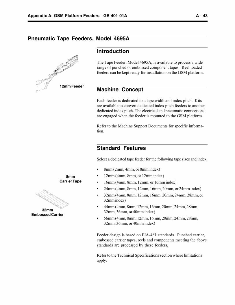
A - 43Appendix A: GSM Platform Feeders - GS-401-01A
Pneumatic Tape Feeders, Model 4695A
Introduction
The Tape Feeder, Model 4695A, is available to process a widerange of punched or embossed component tapes. Reel loadedfeeders can be kept ready for installation on the GSM platform.
Machine Concept
Each feeder is dedicated to a tape width and index pitch. Kitsare available to convert dedicated index pitch feeders to anotherdedicated index pitch. The electrical and pneumatic connectionsare engaged when the feeder is mounted to the GSM platform.
Refer to the Machine Support Documents for specific informa-tion.
Standard Features
Select a dedicated tape feeder for the following tape sizes and index.
• 8mm (2mm, 4mm, or 8mm index)
• 12mm (4mm, 8mm, or 12mm index)
• 16mm (4mm, 8mm, 12mm, or 16mm index)
• 24mm (4mm, 8mm, 12mm, 16mm, 20mm, or 24mm index)
• 32mm (4mm, 8mm, 12mm, 16mm, 20mm, 24mm, 28mm, or32mm index)
• 44mm (4mm, 8mm, 12mm, 16mm, 20mm, 24mm, 28mm,32mm, 36mm, or 40mm index)
• 56mm (4mm, 8mm, 12mm, 16mm, 20mm, 24mm, 28mm,32mm, 36mm, or 40mm index)
Feeder design is based on EIA-481 standards. Punched carrier,embossed carrier tapes, reels and components meeting the abovestandards are processed by these feeders.
Refer to the Technical Specifications section where limitationsapply.
32mmEmbossed Carrier
8mmCarrier Tape
12mm Feeder

A - 44 GS-401-01A - Appendix A: GSM Platform Feeders
Handle
Latch
ComponentReel Holder
1 5a Scrap CarrierTape Exit
6
Component Pick UpPosition
4This End to the GSM
2 Mylar Cover TapeTake-Up Reel
5Peeler Blade
3 Manual FeederIndex Tool
Functional Description
The following sequence of events describe the Tape Feederfunctions. The numbers in parentheses relate to the callouts inthe illustration above.
(1) A component tape reel is mounted on the Component ReelHolder.
(2) The component tape is routed beneath the Take-Up Reel tothe index wheel.
(3) The component tape is advanced through the feeder usingthe Feeder Index Tool.
(4) Pins on the index wheel engage holes in the component tapeadvancing components to the Pickup Position.
(5) The top mylar cover tape is threaded back over the PeelerBlade to the Take-Up Reel while the empty component car-rier tape is routed out through the carrier tape scrap guide.
(6) The Latch locks and releases the feeder on the GSM plat-form.
Supporting Documents
EIA-481 Electronic Industries Association Standard - Tapingof Surface Mount Components for Automatic Place-ment.

A - 45Appendix A: GSM Platform Feeders - GS-401-01A
Technical Specifications for Pneumatic Tape Feeders
Tape Width 8mm 12mm 16mm and 24mm 32mm and 44mm 56mm
Electrical Provided by GSM Provided by GSM Provided by GSM Provided by GSM Provided by GSM
Pneumatic Provided by GSM Provided by GSM Provided by GSM Provided by GSM Provided by GSM
MaximumReel Size
330mm (15.00") 330mm (15.00") 381mm (15.00") 381mm (15.00") 609mm (23.98")
RequiredNumber ofFeederPositions
One One Two Three Four
Tape Type Punched andEmbossedCarrier
Embossed Carrier Embossed Carrier Embossed Carrier Embossed Carrier
Tape Leader 203mm (8") 203mm (8") 203mm (8") 203mm (8") 203mm (8")
Take-UpCapacity
3810cm of 0.10mm(1500" of 0.004")
3810cm of 0.10mm(1500" of 0.004")
3810cm of0.10mm(1500" of 0.004")
3810cm of0.10mm(1500" of 0.004")
3810cm of0.10mm(1500" of 0.004")
IndexingIncrement
2mm to 8mm(0.079" to 0.314")in 2mm (0.079")increments
4mm to 12mm(0.157" to 0.472")in 4mm (0.157")increments
4mm to 32mm(0.157" to 0.787")in 4mm (0.157")increments
4mm to 40mm(0.157" to 1.574")in 4mm (0.157")increments
4mm to 40mm(0.157" to 1.574")in 4mm (0.157")increments
Index Rate inSeconds forSelected TapeIndex1
2mm 0.250 — — — —
4mm 0.250 0.350 1.0 1.0 1.0
8mm 0.250 0.350 1.0 1.0 1.0
12mm — 0.350 1.0 1.0 1.0
16mm — — 1.0 1.0 1.0
20mm — — 1.0 1.0 1.0
24mm — — 2.02 2.02 2.02
28mm — — — 2.02 2.02
32mm — — — 2.02 2.02
36mm — — — 2.02 2.02
40mm — — — 2.02 2.02
Notes:1 The feeder index cycle begins when the Z-axis (spindle) reaches the up position. The default time to
index the next part to the pick position is 0.40, 1.0, or 2.0 seconds, dependent on the feeder model.2 Indicates a double stroke cylinder.

A - 46 GS-401-01A - Appendix A: GSM Platform Feeders
Tape Pocket Depth LimitationsTape Width Pocket Length 1 Pocket Depth
8mm N/A 2.49mm (0.098")
12mm N/A 6.5mm (0.256")
16mm to 24mm N/A 10mm (0.394")
32mm to 56mm Up to 28.9mm (1.140") 10mm (0.394")Between 28.9mm and 35mm 9.14mm (0.360")(1.140" and 1.378" )
1 Tapes with pocket lengths longer than 35mm (1.378") must be evaluated by Universal.
Shown is the maximum distance from thetop of the tape to the top of thecomponent.
Pocket Length
Tape
Component
5.8mm (0.23")

A - 47Appendix A: GSM Platform Feeders - GS-401-01A
Track Feeder, Model 4696A
Introduction
The Track Feeder, Model 4696A, supports and positions compo-nent tubes for component transport to the pick position for pre-sentation. Tracks and feeder bases are sold separately. TheTrack Application Listing contains the component types and di-mensions that can be used on the track feeder.
Consult a Universal Sales Engineer for the Track ApplicationListing.
Machine Concept
The track assembly and the feeder base assembly make up thetrack feeder.
The component-specific track accommodates a maximum of fourtubes. Track assemblies, with or without isolator assemblies, canbe installed on the base assembly.
Modular design of the track feeder permits quick feeder change-over on the GSM platform.
Standard Features
Track Assembly
The component track assembly, with or without an isolator as-sembly, is application specific. Tracks are available for SOIC,LCC, PLCC, SOJ, and MOD DIP components. Select the re-quired track from the Track Application Listing. Tracks with iso-lators are used for the most common component packages. Atrack load assembly or wireform supports the component tubes.
Feeder Base Assembly
The feeder base assembly, with GSM platform mounting, in-cludes the interface and shutter assembly.

A - 48 GS-401-01A - Appendix A: GSM Platform Feeders
Technical SpecificationsRequired Feeder 3 feeder slotsPositions
Service Requirements
Electrical Power is provided by the GSM platform.
Pneumatic Air is provided by the GSM platform.
Feeder Base
2 Track Assembly withIsolator Assembly
1 ComponentTube
3 Interface Assembly (Usedwith Isolator-equipped trackassembly. Removed wheninstalling all others.)
3a Shutter
Functional Description
The following sequence of events describes the Track Feederfunctions. The numbers in parentheses relate to the callouts inthe illustration above.
(1) Components are loaded:
• Automatically from Component Tube.
• Manually from a Component Tube. Nonstandard tubes mayrequire a manual method.
(2) The components move through the Track Assembly to thepickup position. An Isolator relieves component back-pres-sure for ease of component pickup.
(3) The Interface, between the Track and the Feeder Base, in-cludes a Shutter. Components remain in the Track, capturedby the Shutter until the component is picked.

A - 49Appendix A: GSM Platform Feeders - GS-401-01A
Stationary Matrix Tray Platform, Model 4649A
Introduction
The Stationary Matrix Tray Platform, Model 4649A, is a base forup to 177.8mm x 330.2mm (7" x 13") matrix trays. The matrixtray platform requires no power and has no options.
Functional Description
The matrix tray support clamp assembly secures matrix trays forcomponent pickup by the GSM platform.
Technical SpecificationsMaximum 25.4mm (1.0")Component andTray Height
Weight 11.8 kg (26 lbs.)
Required Feeder 8 feeder slotsPositions
Service None required.Requirements
Matrix Tray Pick Limitations (Available axis travel to reach Matrix Tray pockets)GSM Platform Configuration Head/Beam Feeder Bank Outbound 5" Inbound 8.5" Inbound
Standard
GSM 1 Head 1 Front 14.40" N/A N/AGSM 1 Head 1 Rear 4.15" 9.15" N/AGSM 1 Head 2 Front 4.15" N/A N/AGSM 1 Head 2 Rear 14.40" 19.40" N/AGSM 2 Head 1/Beam 1 Front N/A N/A N/AGSM 2 Head 1/Beam 1 Rear 5.24" 10.24" 13.74"GSM 2 Head 2/Beam 2 Front 5.24" N/A N/AGSM 2 Head 2/Beam 2 Rear N/A N/A N/AThis table notes the distances of Y-axis travel from the feeder interface dowel pins to the limit. When configuring therear feeder plate position, users should consider the trade-off between maximum board width, Matrix Tray picklimitations (available travel to reach Matrix Tray pockets), and machine throughput. These limitations do not apply tothe Platform Tray Feeder.

A - 50 GS-401-01A - Appendix A: GSM Platform Feeders
Multi-Tube Feeders, Model 4698A
Introduction
The Multi-Tube Feeder, Model 4698A, delivers a variety of com-ponents from tubes to the pick position on the GSM. The feederis loaded with multiple tubes of the same component type andpart number. It automatically ejects empty tubes and continuesfeeding components. The feeder can be manually loaded withfull tubes while the GSM is operating.
The General Application Placement Head can gang-pick fromthe Multi-Tube Feeders that require two feeder slots.
Standard Features
Each feeder is dedicated to a component style. Universal Instru-ments offers several Multi-Tube Feeders for integration to theGSM platform, including custom designs.

A - 51Appendix A: GSM Platform Feeders - GS-401-01A
The following sequence of events describe the Multi-TubeFeeder functions. The numbers in parentheses relate to thecallouts in the illustration at left.
(1) Tubes are stacked, one on top of the other and at anangle, for gravity feed of components to the singulator/track assembly.
(2) The Singulator retains the second component in line, whileallowing the first component in line to advance to the con-veyor. When the Singulator returns, the line of compo-nents advance by one component length.
(3) The Conveyor indexes the component to the end stop forpick up by the GSM platform head.
(4) An empty tube ejects from the bottom of the feeder andthe next one in the stack drops into position for feeding tothe Singulator.
2
4
1
Technical SpecificationsElectrical Power is provided by the GSM platform.
Pneumatic Air is provided by the GSM platform.
Required Feeder 2 feeder slots for a 40mm feeder track.Positions 3 feeder slots for a 50mm feeder track.
Tube Length 501.6mm to 558.8mm (19.75" to 22.00")
Tube Stack Height 101.6mm (4.00"), maximum
Index Rate Programmable. Recommended minimumsetting is 1.300 seconds.
3
Functional Description
Tube Stacker
TubeEjector
Singulator
Conveyor
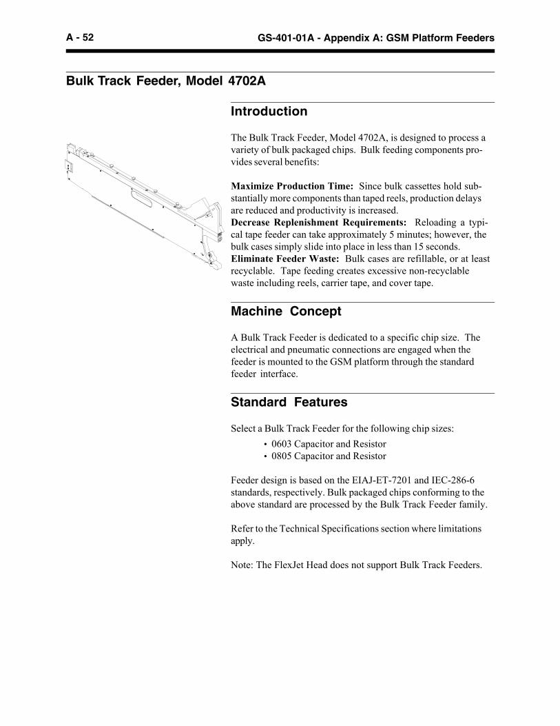
A - 52 GS-401-01A - Appendix A: GSM Platform Feeders
Bulk Track Feeder, Model 4702A
Introduction
The Bulk Track Feeder, Model 4702A, is designed to process avariety of bulk packaged chips. Bulk feeding components pro-vides several benefits:
Maximize Production Time: Since bulk cassettes hold sub-stantially more components than taped reels, production delaysare reduced and productivity is increased.Decrease Replenishment Requirements: Reloading a typi-cal tape feeder can take approximately 5 minutes; however, thebulk cases simply slide into place in less than 15 seconds.Eliminate Feeder Waste: Bulk cases are refillable, or at leastrecyclable. Tape feeding creates excessive non-recyclablewaste including reels, carrier tape, and cover tape.
Machine Concept
A Bulk Track Feeder is dedicated to a specific chip size. Theelectrical and pneumatic connections are engaged when thefeeder is mounted to the GSM platform through the standardfeeder interface.
Standard Features
Select a Bulk Track Feeder for the following chip sizes:
• 0603 Capacitor and Resistor• 0805 Capacitor and Resistor
Feeder design is based on the EIAJ-ET-7201 and IEC-286-6standards, respectively. Bulk packaged chips conforming to theabove standard are processed by the Bulk Track Feeder family.
Refer to the Technical Specifications section where limitationsapply.
Note: The FlexJet Head does not support Bulk Track Feeders.

A - 53Appendix A: GSM Platform Feeders - GS-401-01A
Technical SpecificationsElectrical Power is provided by the GSM
platform
Pneumatic Air is provided by the GSMplatform
Required Feeder Slots One
Index Rate 250 milliseconds
Compatibility Flex Head, High Force Head
Functional Description
The following sequence of events describes the BulkTrack Feeder functions.
(1) Cassette is locked into the bulk cassette mount.(2) Case is mounted to the bulk feeder cassette.(3) Cassette aligns the chips end-to-end.(4) Chips are pneumatically transported to the pick
position via the track.(5) A vacuum nozzle is engaged to separate a com-
ponent from the next component in line.
ConnectorAssembly
VacuumNozzle
Bulk CassetteCaseTrack
Bulk Cassette
Lever
ComponentLabel
Base
LoadButton
Latch
Bulk Cassette
Mount
Metric Size L +/- L W +/-W T +/-T
1608C 1.6000 0.0708 0.8000 0.0700 0.8000 0.0700
1608R 1.6250 0.0750 0.8500 0.0500 0.4400 0.0400
2012C 2.0000 0.1000 1.2500 0.1000 0.6000 0.1000
2012R 2.0000 0.1000 1.2500 0.1000 0.5500 0.0500
Component SpecificationsThe following table lists the component specifications for all BulkTrack Feeders.
Inch Size L +/- L W +/-W T +/-T
0603C 0.0630 0.0028 0.0315 0.0028 0.0315 0.0028
0603R 0.0640 0.0030 0.0335 0.0020 0.0173 0.0016
0805C 0.0787 0.0039 0.0492 0.0039 0.0236 0.0039
0805R 0.0787 0.0039 0.0492 0.0039 0.0217 0.0020

A - 54 GS-401-01A - Appendix A: GSM Platform Feeders
This page intentionally left blank.

B - 55Appendix B: Placement Heads - GS-401-01A
Component HandlingCapabilities
FlexJet 1 Flex High Force UFP 300
mm inch mm inch mm inch mm inch
Maximum(without thetarotation in thecamera housing)
Length 25.400 1.000
Each of these GSM Platform placement heads require the use of anUpward-Looking Camera for image acquisition. Refer to Appendix C,“Cameras,” for applicable component considerations.
Width 25.400 1.000
Height 11.68 0.460
Maximum(with theta rotationin the camerahousing)
Length 17.960 0.707
Width 17.960 0.707
Height 11.68 0.460
Minimum(0201 capabilitypending)
Length 0.500 0.020
Width 1.000 0.040
Height 0.150 0.006
Maximum(Camera SelectionDependent)
Length 50.800 2.000 50.800 2.000 50.800 2.000 50.800 2.000
Width 50.800 2.000 50.800 2.000 50.800 2.000 50.800 2.000
Height 12.700 0.5004 12.700 0.500 12.700 0.500 12.700 0.500
Minimum(Camera SelectionDependent)
Length 0.500 0.020 0.500 0.020 0.500 0.020 0.500 0.020
Width 1.000 0.040 1.000 0.040 1.000 0.040 1.000 0.040
Height 0.150 0.006 0.150 0.006 0.150 0.006 0.150 0.006
Minimum LeadWidth
Upward-Looking Camera Selection DependentRefer to Appendix C, “Cameras,” for details.
Minimum LeadPitch
Minimum BumpDiameter
Minimum BumpPitch
Task Block Thickness Range 5 6.35 0.250 N/A N/A N/A
Placement Force Range (10gincrements)
150 to 1,000 125 to 450 175 to 2,500 6 150 to 10,000
Maximum Component Weight 7 35 35 35 35
Practical Component Range
Standard SMcomponents from chipsto large leaded & area
array components,including a limitedrange of Odd Form
surface mountpackages 8
Mid to large leaded andarray components,
including Odd Form IMor SM packages
requiring up to 450gplacement pressure
Mid to large leaded andarray components,including advancedpackaging and Odd
Form packagesrequiring up to 2,500gplacement pressure
Ultra-fine pitch SM andadvanced packaging,such as flips chips ordie, and Odd Form
packages requiring upto 10,000g placement
pressure
Appendix B: Placement Heads
1 Vacuum pick surface MANDATORY for FlexJet heads. Additional considerations for the FlexJet head include the lack of backlighting capability, co-planarity support, and gripper nozzles. The FlexJet nozzle changers cannot be configured in the Feeder Bank. Finally, there is no support for thin filmapplicator or wafer array feeders; however, support is planned for a future software release.2 Actual component dimensions will vary depending on the pick tolerance applied.3 Special situations exist where specified constraints can be alleviated to accommodate non-standard applications. The GSM platform has placed a146.1mm (5.75") x 12.95mm (0.510") SM connector with special considerations.4 Special situations exist where specified constraints can be alleviated to accommodate non-standard applications. The GSM platform has placed a25.4mm (1.0") tall electrolytic capacitor with special considerations.5 This thickness range is for imaging parts in the same FlexJet task block and is necessary to ensure all components are centered within the specifiedfocal plane of the camera.6 Requires the optional Heavy Spring Kit and Transformer Readout Assembly for calibration and maintenance.7 Special situations exist where specified constraints can be alleviated to accommodate non-standard applications. The GSM platform has placed a 56gram CCGA using a specific vacuum nozzle.
8 The FlexJet component range is continually expanding. Consult GSM Applications Engineer for a review of specific components.
Notes:
On-
the-
Hea
d C
amer
a 2U
pwar
d-Lo
okin
gC
amer
a 3
Com
pone
nt C
hara
cter
istic
s

B - 56 GS-401-01A - Appendix B: Placement Heads
X, Y: ±62µm with Cpk >1.33, using Upward-Looking Camera(CP >1.67)
X, Y: ±75µm with Cpk >1.33, using On-the-Head Camera(CP >1.67)
θ: ±0.2° with Cpk >1.33, using either camera
Note: Components of 0.5mm pitch or finer should be placed using Upward-Looking Camera.
1
1
1 Verified with all components of variation included: all spindles at all rotations overentire placement area for multiple boards and for each head and camera combination.Glass slugs placed on glass plate. Data analyzed by placement site.
Placement Performance Specification for Chips
X, Y: ±100µm with Cpk >1.33, using either camera(CP >1.67)
Component 150g to 1,000g, in 10g incrementsPlacement ForceRange
Final Placement 50 defects per million (dpm)Performance
Intrinsic Availability 98%
FlexJetHead
This general purpose 7-spindle head, with 20mm spacing betweeneach spindle and on-the-head camera, handles the broadest rangeof surface mount components. This head offers the best mix ofaccuracy and speed for most surface mount applications.
Adding a second FlexJet head to a GSM platform reduces thenumber of nozzle changes when building a product. In addition,full access to matrix tray feeders is gained from all feeder banks.
In addition, GSM platform software offerings have increased toinclude FlexJet Optimization and Simulation programs. Roundingout FlexJet technology is a Nozzle Changer that accomodates 28nozzles and allows for programmed, one second, gang nozzlechanges.
FlexJet® Head
Placement Performance Specification for Leaded and ArrayComponents

B - 57Appendix B: Placement Heads - GS-401-01A
The Mean is the arithmeticaverage of a set ofmeasurements.
Standard Deviation is ameasure of the variability of aprocess output.
Accuracy is the distancebetween the mean and thetarget value.
Repeatability is one standarddeviation.
Cp is a capability index whichcompares the spread of theprocess to the distancebetween the upper and lowerspecifications.
Cpk is the process capabilityindex, which is a measure ofthe process's ability to produceproduct within specifications.
75% lead-to-pad @ 6σ by placement
X, Y: ±50µm @ ±5σ (CP > 1.67)θ: ±0.2° @ ±5σ(CP > 1.67)
X, Y: Repeatability < 10µmθ: Repeatability < 0.04°
X, Y, θ: Cpk > 1.5
1 Assumes: Lead Width = Pitch x 0.5, Pad Width = LeadWidth x 1.25, Span = 38.1mm (1.5").2 Verified with all components of variation included: allspindles at all rotations over entire placement area for mul-tiple boards and for each head and camera combination.Glass slugs placed on glass plate.
Cp= Upper Spec Limit - Lower Spec Limit
6σwhere σ = the standard deviation
of the sample
Cpk=
min(x - Lower Spec Limit, Upper Spec Limit - x )
3σ
where σ= the standard deviation of the sample and x is the sample mean
2
LSL USL
Target
Mean
Accuracy
±1σ±2σ±3σ
Flex Head and High Force Head
The Flex Head is a general purpose 4-spindle head, with 40mmspacing between each spindle. This head offers added flexibilityby placing odd form as well as most standard surface mountcomponents.
Adding a second Flex Head reduces the number of nozzlechanges when building a product. In addition, full access to ma-trix tray feeders is gained in all feeder banks of the GSM plat-form.
Universal’s High Force Head is essentially the same as theFlex Head, but it expands the placement force from 175 grams to2,500 grams with a force verification unit. It also provides a highvolume die placement solution for applications such as flip chipand bare die attach, in addition to flexible fine pitch placement.
Placement Performance Specification1

B - 58 GS-401-01A - Appendix B: Placement Heads
GSM throughput specifications have been achieved by running benchmarkproducts with the following significant characteristics. All throughputspecifications exclude board transfer, fiducial inspection, and bad board sensetimes. Actual product throughput may vary with each application.1 Based on (48) Chip-1206 component placements from 8mm tape feeders on a
457.2mm x 406.4mm (18" x 16") board with feeder duplication, gang-picking,and On-the-Head Centering (FlexJet Head) or 4.0 mil/pixel Upward LookingCamera Station (Flex or High Force Heads). Can be verified using 1206 SpeedVerification Kit, part number 48884501.2 Based on (42) PLCC44 component placements from 32mm Multi-Pitch TapeFeeders on a 254.0mm x 203.2mm (10" x 8") board with feeder duplication,gang-picking, and On-the-Head Centering (FlexJet Head) or 4.0 mil/pixelUpward Looking Camera Station (Flex or High Force Heads). Can be verifiedusing PLCC44 Speed Verification Kit, part number 48884601.3 Based on (36) PLCC84 component placements from 44mm Multi-Pitch TapeFeeders on a 254.0mm x 203.2mm (10" x 8") board with feeder duplication andOn-the-Head Centering (FlexJet Head) or 4.0 mil/pixel Upward Looking CameraStation (Flex or High Force Heads). Can be verified using PLCC84 SpeedVerification Kit, part number 48884701.4 Application dependency is related to component type and size, feederpackaging, accessory feeders such as PTF or shuttle, component featuresprogrammed, and any requirements for special nozzles.
GSM Platform: Placement Specifications
GSM1 Tact Time CPH
w/ FlexJet Head (front) & High Force Head (rear)
1Components < 12mm 0.36-0.80 second 4500-10000 cph
2Components > 12mm – < 25mm 0.51-1.03 seconds 3500-7000 cph
3Components > 25mm – < 32mm 1.00-1.80 seconds 2000-3600 cph
4Components > 32mm Application dependent
w/ FlexJet Head (front)
1Components < 12mm 0.36 second 10000 cph
2Components > 12mm – < 25mm 0.51 second 7000 cph
3Components > 25mm – < 32mm 1.00 second 3600 cph
4Components > 32mm Application dependent
w/2 Flex Heads
1Components < 12mm 0.67 second 5400 cph
2Components > 12mm – < 25mm 0.90 second 4000 cph
3Components > 25mm – < 32mm 1.64 seconds 2200 cph
4Components > 32mm Application dependent
GSM2 Tact Time CPH
w/2 FlexJet Heads
1Components < 12mm 0.18 second 20000 cph
2Components > 12mm – < 25mm 0.36 second 10000 cph
3Components > 25mm – < 32mm 0.80 second 4500 cph
4Components > 32mm Application dependent
w/2 Flex Heads
1Components < 12mm 0.36 second 10000 cph
2Components > 12mm – < 25mm 0.60 second 6000 cph
3Components > 25mm – < 32mm 0.90 second 4000 cph
4Components > 32mm Application dependent

B - 59Appendix B: Placement Heads - GS-401-01A
UFP300+ Head (GSM1 only)
Compatible Features and OptionsConfiguration The UFP300+ Head accesses the camera,
feeders, nozzle changer and coplanarity on thesame side as the head installation.
Components are picked from feeder slotpositions 2 to 35 and 38 to 71.
GSM1 machines with the rear feeder bank in theinbound (127mm/5") board configurationrequire the UFP300+ Head be installed on the frontof the beam.
UFP300+ HighAccuracy
Head
X YLengthWidth
Placement Specifications (UFP300+ head)Placement Rate 800 cph1
Final Placement 50 defects per million (dpm)Performance
Intrinsic Availability 98%1 Based on picking 304-pin glass slugs from a matrix tray using a highmagnification (1.3 mil/pixel) camera.
X, Y: ±38µm @ ±5σ (CP > 1.67)θ: ±0.1° @ ±5σ (CP > 1.67)
X, Y: Repeatability < 7.6µmθ: Repeatability < 0.02°
X, Y, θ: Cpk > 1.5
1 Verified with all components of variation included: all rotations over en-tire placement area for multiple boards and for each head and cameracombination. Glass slugs placed on glass plate.
Placement Performance Specification1

B - 60 GS-401-01A - Appendix B: Placement Heads
Dispense Specifications 1
Cartridges 10cc and 30cc, customer supplied
Dispense Rate Both numbers contingent uponDispense Tact Time application. Contact a
Universal Sales Engineer.
Intrinsic 98%Availability
Nominal: 1, 2
X, Y Accuracy 0.020mm (±0.0008")
X, Y Repeatability (σ) 0.018mm (<0.0007")
Diameter 0.013mm (<0.0005")Repeatability (σ)
Verified to: 1, 2
X, Y Accuracy 0.076mm (±0.003")
X, Y Repeatability (σ) 0.051mm (<0.002" )
Diameter 0.038mm (<0.0015")Repeatability (σ)
1 Using a Universal Instruments certified adhesive. Resultsvary with material, axis moves and Z-stroke requirements.2 Based on 0.508mm ( 0.020") dot at 2.54mm (0.100") X, Y,and Z.
Dispense Heads (GSM1 only)
PositiveDisplacementPump Head
ArchimedesMetering Valve

B - 61Appendix B: Placement Heads - GS-401-01A
Spindle 1 Small Minimum Dot Size Requirement is 0.508mmSingle Dot (0.020")
Spindle 2 Dual Dot Minimum Dot Size Requirement is 0.762mmat 0° (0.030")
Spindle 3 Dual Dot Minimum Dot Size Requirement is 0.762mmat 90° (0.030")
Spindle 4 Large Minimum Dot Size Requirement is 1.016mmSingle Dot (0.040")
Notes: Standard nozzles are only intended for dispensing adhesivebetween component pads that do not have solder paste printed onthem.
The 4 Standard Nozzles that ship with the GSM dispense head cannotbe exchanged for other special nozzles. If it is determined that specialnozzles are required, the customer must purchase them.
Dispensing Nozzle ToolingConfigurationsStandard Nozzle Tooling Configurations are included with thepurchase of either the Piston Positive Displacement Style Pump or theArchimedes Metering Valve Style Pump.
Standard Nozzle Tooling encompasses the following:

B - 62 GS-401-01A - Appendix B: Placement Heads
This page intentionally left blank.
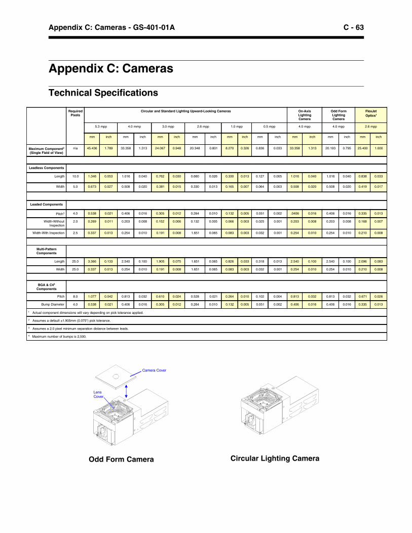
C - 63Appendix C: Cameras - GS-401-01A
Appendix C: Cameras
Technical Specifications
Circular Lighting Camera
LensCover
Camera Cover
Odd Form Camera
RequiredPixels
Circular and Standard Lighting Upward-Looking Cameras On-AxisLightingCamera
Odd FormLightingCamera
FlexJetOptics1
5.3 mpp 4.0 mmp 3.0 mpp 2.6 mpp 1.0 mpp 0.5 mpp 4.0 mpp 4.0 mpp 2.6 mpp
mm inch mm inch mm inch mm inch mm inch mm inch mm inch mm inch mm inch
Maximum Component2
(Single Field of View)n\a 45.436 1.789 33.358 1.313 24.067 0.948 20.348 0.801 8.270 0.326 0.836 0.033 33.358 1.313 20.193 0.795 25.400 1.000
Leadless Components
Length 10.0 1.346 0.053 1.016 0.040 0.762 0.030 0.660 0.026 0.330 0.013 0.127 0.005 1.016 0.040 1.016 0.040 0.838 0.033
Width 5.0 0.673 0.027 0.508 0.020 0.381 0.015 0.330 0.013 0.165 0.007 0.064 0.003 0.508 0.020 0.508 0.020 0.419 0.017
Leaded Components
Pitch3 4.0 0.538 0.021 0.406 0.016 0.305 0.012 0.264 0.010 0.132 0.005 0.051 0.002 .0406 0.016 0.406 0.016 0.335 0.013
Width-WithoutInspection
2.0 0.269 0.011 0.203 0.008 0.152 0.006 0.132 0.005 0.066 0.003 0.025 0.001 0.203 0.008 0.203 0.008 0.168 0.007
Width-With Inspection 2.5 0.337 0.013 0.254 0.010 0.191 0.008 1.651 0.065 0.083 0.003 0.032 0.001 0.254 0.010 0.254 0.010 0.210 0.008
Multi-PatternComponents
Length 25.0 3.366 0.133 2.540 0.100 1.905 0.075 1.651 0.065 0.826 0.033 0.318 0.013 2.540 0.100 2.540 0.100 2.096 0.083
Width 25.0 0.337 0.013 0.254 0.010 0.191 0.008 1.651 0.065 0.083 0.003 0.032 0.001 0.254 0.010 0.254 0.010 0.210 0.008
BGA & C44
Components
Pitch 8.0 1.077 0.042 0.813 0.032 0.610 0.024 0.528 0.021 0.264 0.010 0.102 0.004 0.813 0.032 0.813 0.032 0.671 0.026
Bump Diameter 4.0 0.538 0.021 0.406 0.016 0.305 0.012 0.264 0.010 0.132 0.005 0.051 0.002 0.406 0.016 0.406 0.016 0.335 0.013
1 Actual component dimensions will vary depending on pick tolerance applied.
2 Assumes a default ±1.905mm (0.075") pick tolerance.
3 Assumes a 2.0 pixel minimum separation distance between leads.
4 Maximum number of bumps is 2,500.

C - 64 GS-401-01A - Appendix C: Cameras
This page intentionally left blank.

D - 65Appendix D: Board Handling - GS-401-01A
Appendix D: Board Handling
Dual Lane Board Handling
There are six zones within the dual lane option. Zones A, C, D,and F are used for input / output board stationing. Zones B and Eare used for board populating.
Up to three boards are staged in the GSM at one time. Typically,two boards are in zones B and E and one board is in any of theother four input / output stations.
The dual lane software follows the first in, first out model. Thefirst board entering the GSM is also the first board exiting themachine. Both lanes utilize the same GSM product.
A
B
C
D
E
F

D - 66 GS-401-01A - Appendix D: Board Handling
Technical Specifications
Maximum Board Width Configuration2
Nozzle Changer Rear Feeder Maximum BoardLocation Plate Position Width 1
Between rails outbound 216.0mm (8.5")1 Board edge clearance of 5mm (0.195") is standard; optional
3mm (0.117") edge clearance reduces maximum board widthby 6.35mm (0.250").
2 Other configurations available. Consult a UniversalSales Engineer.
Dual Lane Board Handling:
• This configuration supports a 12.7mm (0.5") maximumbottomside clearance for the first inch measured from thefront of the board. See illustration below.
• Board widths less than 89.0mm (3.5") require the removal ofa board stop from each lane.
Fixed front railRear rail
12.7mm (0.5")clearance under board
P.C. board section
Maximum Underboard Clearance Area
component
com
pone
nt
25.4mm (1.0")
25.4mm (1.0") clearance under board
P.C. board rails

E - 67Appendix E: Odd Form Assembly - GS-401-01A
Appendix E: Odd Form Assembly Capabilities
Introduction
The flexibility of the GSM platform offers manufacturers a highthroughput alternative to manual assembly for odd form throughhole and surface mount components. By automating odd form as-sembly, manufacturers produce cost-effective products while im-proving product quality.
To help customers automate their odd form and light electrome-chanical assembly, Universal’s Surface Mount Division providesknowledge-based services to resolve viability issues. These ser-vices include evaluating components, packaging formats, andfeeders; and design guidelines for printed circuit board lead-to-hole ratios, component density, and insertion forces.
Applications
This Appendix covers the odd form capabilities of the GSM plat-form. Included is a list of components that have been inserted bythe GSM platform. If you have questions or concerns relative toyour specific application, it is recommended that you meet with aUniversal Sales Engineer to discuss your application.

E - 68 GS-401-01A - Appendix E: Odd Form Assembly
Components
The GSM platform has been configured to readily handle the fol-lowing odd form components:
Odd form components vary from vendor to vendor. Retentionfeatures and their respective hole sizes need to be analyzed, aswell as tooling clearances between components.
If your component type does not appear on this list, please con-tact a Universal Sales Engineer.
Audio Jacks PLCC Sockets
Card Edge Connectors Power Headers
Crystal Oscillators Radial Lead Components
DIMM Connectors Relays
DIN Connectors Shrouded Headers
Displays SIMM Connectors
D-Shell Connectors Speakers
Headers Transformers
LEDS USB Connectors
Phone Jacks ZIF (Socket 7) Connectors

E - 69Appendix E: Odd Form Assembly - GS-401-01A
The UFP 300+ Placement Head assembly is the machine’s op-tional ultra-fine pitch placement head. It is a single spindle headand is comprised of two major subassemblies: the Theta-Moduleassembly, and the Z-axis assembly. The spindle accepts a varietyof different nozzles, allowing pick-up and transport of variouscomponent sizes and types. It is capable of accurately placingcomponents with up-to or more-than 300 leads, and at rotationalincrements as small as 0.001°. The single-spindle UFP (UltraFine Pitch) Head can be mounted on a GSM1 to achieve inser-tion force up to 10,000 grams.
Component Tolerances
Maximum Component RangeLength 127 mm (5.0")Width 63.5 mm (2.5")Overall Height (body + lead) 21 mm (0.825")Height above board - staged 15.7 mm (0.620")Height above board - non-staged 17.8 mm (0.700")
High Force Head
The High Force Head assembly is the component pick-up andplacement mechanism, with required enhancements to accommo-date C4 or odd form type components. It is a four spindle headwith each spindle having vertical and rotational movement capa-bility. The spindles are driven in the vertical direction by a singleZ-axis motor (with each spindle individually clutched) for compo-nent pick-up and placement. Each spindle accepts a variety ofdifferent nozzles, allowing pick-up and transport of various com-ponent sizes and types.
High Force Head
UFP 300+ Head (GSM1 only)
UFP 300+ HighAccuracy Head

E - 70 GS-401-01A - Appendix E: Odd Form Assembly
Passive Clinch Option
The optional feeder clinch plate is dedicated to a specific boardapplication. This device ensures that radial leaded componentsare secured to the board, allowing for transport or flipping ofPCB during assembly.
Speed
Actual throughput will typically be between 2 and 4 seconds percomponent, depending on force requirements, opportunities togang pick, and field of view requirements.
Vision On-the-Fly
The GSM platform is equipped with Vision On-the-Fly forthrough hole components. It also allows for lead inspection andregistration. Its inherent flexibility eliminates the need for feederregistration of components.
Feeders
The following are available odd form component feeders for usewith the GSM platform:
Consult with a Universal Sales Engineer for component-specificfeeder tooling.
Cameras
A specialized camera offers vision-assisted placement of oddform and light electromechanical assembly components. Avail-able in a standard magnification of four mils/pixel, this cameraemploys a special “cone” cover. The cone helps direct the light insuch a way that the ends of the leads of odd form componentscan be seen. The cone opening is only 1-1/8" wide.OFA Camera
LensCover
Camera Cover
Radial Tape Feeder GPAX Feeder
Multi-Tube Feeder Matrix Tray Platform
Connector Feeder(SIMM/DIMM)
Vibratory Bowl
F - 71Appendix F: GSM Platform Traceability - GS-401-01A
Appendix F: GSM Platform Traceability
Bar Code Changeover Option
Introduction
The GSM platform is capable of handling bar code changeovers ifit is equipped with the Bar Code Changeover option. This optionallows for seamless product changeovers without requiring the userto manually load product data or press the start button. Thechangeover is accomplished based on a bar code string being pre-sented to bar code reading hardware mounted to one of the boardhandling lane’s upline conveyors. Once the bar code string is re-ceived, a lookup is performed in a cross-reference lookup table toverify what product should be executed for the given bar code.
This option is completely local to the GSM platform. No externalhost machine is required. It is a separate purchased option to theUPS software.
Restrictions/Limitations
The Bar Code Changeover option is only supported on StagedBoard Handling hardware with the SMEMA protocol. Each boardhandling lane requires bar code reading hardware mounted on theupline conveyor. Additionally, each bar code reader requires a se-rial line to the ISIO board. Dual Lane Board Handling requires twicethe scanning hardware as Staged Board Handling.
Only printed circuit boards for the current product will be allowedin the machine. Any board requiring a product changeover will bemaintained outside the machine until all current boards have exitedthe machine and the product changeover has been performed.
Before the GSM platform can be placed into either Line Monitor orChangeover mode, it must be powered up and the amplifiers en-abled by pressing the “hard” start button. If pallets are utilized, onlyone bar code in the set is used as the main product identification.
ACE conveyors and Universal-supplied bar code readers are recom-mended. Should different conveyors or scanners be desired, therewill be additional fees for integration consulting and required parts/labor.
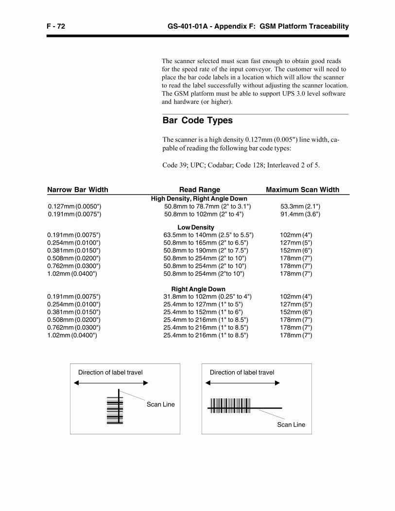
F - 72 GS-401-01A - Appendix F: GSM Platform Traceability
Bar Code Types
The scanner is a high density 0.127mm (0.005") line width, ca-pable of reading the following bar code types:
Code 39; UPC; Codabar; Code 128; Interleaved 2 of 5.
The scanner selected must scan fast enough to obtain good readsfor the speed rate of the input conveyor. The customer will need toplace the bar code labels in a location which will allow the scannerto read the label successfully without adjusting the scanner location.The GSM platform must be able to support UPS 3.0 level softwareand hardware (or higher).
Narrow Bar Width Read Range Maximum Scan WidthHigh Density, Right Angle Down
0.127mm (0.0050") 50.8mm to 78.7mm (2" to 3.1") 53.3mm (2.1")0.191mm (0.0075") 50.8mm to 102mm (2" to 4") 91.4mm (3.6")
0.191mm (0.0075") 63.5mm to 140mm (2.5" to 5.5") 102mm (4")0.254mm (0.0100") 50.8mm to 165mm (2" to 6.5") 127mm (5")0.381mm (0.0150") 50.8mm to 190mm (2" to 7.5") 152mm (6")0.508mm (0.0200") 50.8mm to 254mm (2" to 10") 178mm (7")0.762mm (0.0300") 50.8mm to 254mm (2" to 10") 178mm (7")1.02mm (0.0400") 50.8mm to 254mm (2"to 10") 178mm (7")
Right Angle Down0.191mm (0.0075") 31.8mm to 102mm (0.25" to 4") 102mm (4")0.254mm (0.0100") 25.4mm to 127mm (1" to 5") 127mm (5")0.381mm (0.0150") 25.4mm to 152mm (1" to 6") 152mm (6")0.508mm (0.0200") 25.4mm to 216mm (1" to 8.5") 178mm (7")0.762mm (0.0300") 25.4mm to 216mm (1" to 8.5") 178mm (7")1.02mm (0.0400") 25.4mm to 216mm (1" to 8.5") 178mm (7")
Direction of label travel
Scan Line
Direction of label travel
Scan Line
Low Density

F - 73Appendix F: GSM Platform Traceability - GS-401-01A
Platform Setup Validation (PSV) Option
Introduction
The GSM platform also supports Platform Setup Validation(PSV), which prevents operator-related errors during feedersetup or reloading by verifying the correct components are loadedinto the correct feeder slots. PSV minimizes product costs by re-ducing rework, thereby improving product yield while providing avalidation log, which tracks each feeder dismount, scan, andmount routines. Minimal operator training is required due to thesimple closed-loop operation and common look of the graphicalWindows®-based user interface.
Incorporating PSV provides numerous benefits:• Prevents operator related loading errors: The closed-
loop feedback system ensures the correct feeders and com-ponents are loaded into the appropriate feeder slot whenevera tape feeder is mounted on the GSM platform.
• Eliminates costly rework: Since PSV will never enable amismatched component and feeder slot, the wrong compo-nents are simply not picked, thus preventing any associatedrework.
• Improves product yield: Again, PSV ensures correct com-ponent usage. This means you will never be forced to reworkboards because the wrong part was placed. Hence, your firstpass product yield may increase.
• Minimizes product costs: PSV always ensures the correctcomponent is loading in its corresponding slot. In doing so,you can rest assured the GSM platform will not place incor-rect parts onto your boards. Since this type of rework isavoided, less labor and materials are needed during boardproduction.
Bottom line, Universal’s closed-loop bar code scanning optionsaves time and money, while ensuring the production of highquality boards.
PSV Specifications• At least UPS 3.1 hardware and software.• Supported Bar Code Label Formats:
Codes 11, 39, 93, and 128; UPC-A and E (not expanded);EAN/JAN; Standard 2 of 5; Interleaved 2 of 5; Codabar.

F - 74 GS-401-01A - Appendix F: GSM Platform Traceability
This page intentionally left blank.