gt2017 64051 - core.ac.uk
TRANSCRIPT
1
GT2017-64051
MICROSTRUCTURE BASED MATERIAL-SAND PARTICULATE INTERACTIONS AND
ASSESSMENT OF COATINGS FOR HIGH TEMPERATURE TURBINE BLADES
Dr. Muthuvel Murugan, Dr. Anindya Ghoshal, Dr. Michael Walock, Dr. Andy Nieto, Dr. Luis Bravo,
Mr. Blake Barnett, Mr. Marc Pepi, and Dr. Jeffrey Swab U.S. Army Research Laboratory, Aberdeen Proving Ground, MD, USA
Mr. Robert Tyler Pegg,
Mr. Chris Rowe NAVAIR
Patuxent River, MD, USA
Dr. Dongming Zhu NASA Glenn Research Center
Cleveland, OH, USA
Mr. Kevin Kerner AMRDEC - ADD
Fort Eustis, VA, USA
ABSTRACT
Gas turbine engines for military/commercial fixed-
wing and rotary wing aircraft use thermal barrier coatings
in the high-temperature sections of the engine for
improved efficiency and power. The desire to further
make improvements in gas turbine engine efficiency and
high power-density is driving the research and
development of thermal barrier coatings with the goal of
improving their tolerance to fine foreign particulates that
may be contained in the intake air. Both commercial and
military aircraft engines often are required to operate
over sandy regions such as in the middle-east nations, as
well as over volcanic zones. For rotorcraft gas turbine
engines, the sand ingestion is adverse during take-off,
hovering near ground, and landing conditions. Although
most of the rotorcraft gas turbine engines are fitted with
inlet particle separators, they are not 100% efficient in
filtering fine sand particles of size 75 microns or below.
The presence of these fine solid particles in the working
fluid medium has an adverse effect on the durability of
turbine blade thermal barrier coatings and overall
performance of the engine. Typical turbine blade damage
includes blade coating wear, sand glazing, Calcia-
Magnesia-Alumina-Silicate (CMAS) attack, oxidation,
and plugged cooling holes, all of which can cause rapid
performance deterioration including loss of aircraft. The
objective of this research is to understand the fine
particle interactions with typical turbine blade ceramic
coatings at the microstructure level. Finite-element based
microstructure modeling and analysis has been performed
to investigate particle-surface interactions, and restitution
characteristics. Experimentally, a set of tailored thermal
barrier coatings and surface treatments were down-
selected through hot burner rig tests and then applied to
first stage nozzle vanes of the gas generator turbine of a
typical rotorcraft gas turbine engine. Laser Doppler
velocity measurements were performed during hot burner
rig testing to determine sand particle incoming velocities
and their rebound characteristics upon impact on coated
material targets. Further, engine sand ingestion tests were
carried out to test the CMAS tolerance of the coated
nozzle vanes. The findings from this on-going
collaborative research to develop the next-gen sand
tolerant coatings for turbine blades are presented in this
paper.
INTRODUCTION Over the years, through consistent efforts in advanced
materials development, scientists and engineers have
significantly improved the efficiency and power densities of gas
turbine engines by increasing the turbine inlet temperature using
high-temperature capable blade materials and coatings.
Traditionally, foreign object damage (FOD) has been the
primary concern in aviation and tank automotive gas turbine
engines. Current state-of-the-art inlet particle separators
equipped in gas turbine engines can remove most of the larger
sized particles (greater than ~75 µm) from the inlet air. This, in
https://ntrs.nasa.gov/search.jsp?R=20170008019 2019-08-29T23:38:06+00:00Zbrought to you by COREView metadata, citation and similar papers at core.ac.uk
provided by NASA Technical Reports Server

2
combination with high-quality, erosion-resistant coatings on the
compressor sections, has significantly reduced the risk from
FOD in the cold sections of the engine. However, fine micron-
sized particles (consisting of ash, soot, dust, and/or sand) can
still pass through the engine and create problems in the hot-
sections, where the operating temperatures of modern gas
turbine engines typically surpass the melting point of many of
these contaminants. The resulting impact, adhesion, melt
infiltration and/or glassy solidification of these small particles
can significantly damage the hot-section components within the
gas turbine engine [1].
High pressure gas generator turbine blades typically
experience inlet temperatures of 1300-1600ºC, requiring TBCs
to be used as thermal insulators on the turbine blades to reduce
blade cooling needs. Current state-of-the-art gas turbine blade
technology has four layers in the high temperature turbine blade
coating system that consists of different materials with specific
properties and functions. These layers are (i) the Ni-based
superalloy substrate, (ii) bond coat, (iii) thermally grown oxide
(TGO) (Alumina, Al2O3), and (iv) the ceramic top-coat (YSZ,
Yttria stabilized Zirconia) [2, 3]. These four layers and their
nominal coating thickness ranges are shown in Figure 1. These
discrete multilayer materials have shown vulnerability to intake
flows that contain sand, dust, and/or fly ash, which adhere and
react at high temperatures and cause premature component
failure through both impingement and combined mechanical-
thermal-chemical attack. Currently there are no valid
fundamental physics based models [1-3] to describe the
complex phenomena of molten particulate impingement,
adhesion and melt infiltration into the ceramic TBCs, followed
by subsequent phase change to glassification [4,5] and
underlying chemical oxidation leading to failure/delamination
of the coating layers. A collaborative research effort at the U.S.
Army Research Laboratory (ARL), with the U.S. Army
Aviation and Missile Research, Development, and Engineering
Center (AMRDEC), the U.S. Navy Naval Air Systems
Command (NAVAIR) and the National Aeronautics and Space
Admininstration (NASA), has been initiated to conduct research
to understand the complex fine sand particulate interaction
mechanisms with thermal barrier coatings and bulk material
substrates [6-12].
Field-returned engine hardware from Army rotorcraft from
Southwest Asia (SWA) shows a significant number of
occurrences of sand-induced damage (Figure 2) [13]. Army
rotorcraft engines are being pulled out of service at a substantial
knockdown on the design life. Commercial jet engines flying
over dust polluted urban areas in some parts of Far East Asia
and South Asia also find sub-micron particles in a molten/semi-
molten state after passing through the combustor. Novel TBCs
which are also resistant to sand-induced surface degradation can
greatly reduce vulnerability in hostile particle-laden
environments and increase fuel efficiency of gas turbine engines
for both the military rotorcraft and civil aircraft fleet. Figures
3(a) and 3(b) show sand-induced CMAS (Calcium-Magnesium-
Aluminum-Silicates) formation on field returned engine
hardware (turbine shroud) and from an engine sand ingestion
test using AFRL03 sand showing good correlation of CMAS
presence. This paper outlines the continued research efforts at
ARL to develop novel TBCs that are sand-phobic with
excellent resistance to impact wear and CMAS adherence,
together with excellent thermal strain tolerance and very low
thermal conductivity properties for improved performance of
future gas turbine engines.
Figure 1. Typical Gas Turbine Blade with a top-coat and a bond
coat with thermally grown Al-oxide layer [3] (Reprinted with
permission from AAAS).
Typical build-up on vane Typical build-up on blade
Figure 2: Engine turbine nozzle and rotor blades with typical
sand-induced damage.
Figure 3(a). Field-returned and Engine Test Hardware
(GTE shroud) showing CMAS formation.

3
CMAS
YSZ
PtAl
IN 718
CMAS
YSZ
Figure 3(b). Detailed Microscopic image and elemental
analysis of CMAS formed on the Engine Test Shroud.
NOMENCLATURE APS Air Plasma Spray
AFRL Air Force Research Laboratory
ARL Army Research Laboratory
AMRDEC Army Aviation and Missile Research,
Development, and Engineering Center
CMAS Calcia-Magnesia-Alumina-Silicate
CMC Ceramic Matrix Composite
CFD Computational Fluid Dynamics
CTE Coefficient of Thermal Expansion
EB-PVD Electron Beam Physical Vapor Deposition
EBC Environmental Barrier Coating
FOD Foreign Object Damage
HVAF High Velocity Air-Fuel
HVOF High Velocity Oxy-Fuel
m/s meters per second
µm micrometer
ms milliseconds
NAVAIR Naval Air Systems Command
NASA National Aeronautics and Space Administration
SEM Scanning Electron Microscope
SiC Silicon Carbide
SPPS Solution Precursor Plasma Spray
SWA Southwest Asia
SPD Supersonic Particle Deposition
TBC Thermal Barrier Coating
TGO Thermally Grown Oxide
YSZ Yttria Stabilized Zirconia
PARTICLE INTERACTIONS RESEARCH STUDY Technical challenges involve modeling complex thermo-
mechanical interactions of mechanics of particle impact and
adherence. The particles can be fully or partially molten or
remain in their solid state after flowing through the combustor
depending upon their size, morphology, geological location and
composition (sand melting point varies between ~ 1050 – 1250
°C). Since the particle impact on turbine blades is much more
complex with multi-physics phenomena including thermo-
mechanical interactions and chemical reactions, a step-by-step
canonical approach is being taken at the U.S. Army Research
Laboratory to study the blade surface-particle interaction.
Figure 4 describes the damage mechanisms as intrinsic and
extrinsic in nature [14]. Intrinsic damage evolutions are caused
by thermo-mechanical fatigue characteristics of the coating and
substrate materials and their interface bonding strengths.
Extrinsic damage evolutions are influenced by particle impact
causing wear and erosion of TBC. Further, the molten sand
deposition, infiltration into the micro-gaps of TBC and the
solidification causes the TBC to lose its thermal strain tolerance
leading to typical horizontal cracks and subsequent
delamination of TBC.
Figure 4. Typical damage mechanisms due to particulate
interactions with TBC layer [14]
As a first step, a spherical particle (quartz sand
composition) impacting a flat target made of typical
turbomachinery material was developed using a nonlinear
dynamic impact analysis finite-element code, LS-DYNA [15].
Researchers in the past have developed semi-empirical erosion
models by studying the rebound characteristics of sand particles
impacting turbomachinery materials [17-20]. Figure 5 is a SEM
image of a typical gas turbine blade showing the columnar
structure of the 7YSZ TBC layer. In this research effort, a
micro-structure finite-element model similar to the micro-
structure of TBC on a substrate has been developed, as shown
in Figure 6, to study the particle impact physics including
particle kinematics, propensity of particulate adhesion to the
surface and buildup in addition to local damage on target
material surfaces. The meso-scale finite-element model is being
extended to further develop simulation of liquid sand particle
(molten sand) impacting a thermal barrier coated turbine blade
surface as the next step. Further, the model shown in Figure 6
was modified to simulate multiple sharp-edged fine sand
particles. Figure 7 shows the typical substrate/TBC model with
multiple irregular, sharp-edged sand particles of 50 µm in mean
size (equivalent geometry envelope diameter).
4
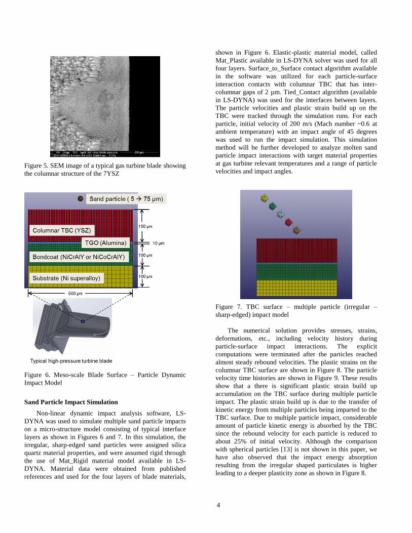
Figure 5. SEM image of a typical gas turbine blade showing
the columnar structure of the 7YSZ
Figure 6. Meso-scale Blade Surface – Particle Dynamic
Impact Model
Sand Particle Impact Simulation
Non-linear dynamic impact analysis software, LS-
DYNA was used to simulate multiple sand particle impacts
on a micro-structure model consisting of typical interface
layers as shown in Figures 6 and 7. In this simulation, the
irregular, sharp-edged sand particles were assigned silica
quartz material properties, and were assumed rigid through
the use of Mat_Rigid material model available in LS-
DYNA. Material data were obtained from published
references and used for the four layers of blade materials,
shown in Figure 6. Elastic-plastic material model, called
Mat_Plastic available in LS-DYNA solver was used for all
four layers. Surface_to_Surface contact algorithm available
in the software was utilized for each particle-surface
interaction contacts with columnar TBC that has inter-
columnar gaps of 2 µm. Tied_Contact algorithm (available
in LS-DYNA) was used for the interfaces between layers.
The particle velocities and plastic strain build up on the
TBC were tracked through the simulation runs. For each
particle, initial velocity of 200 m/s (Mach number ~0.6 at
ambient temperature) with an impact angle of 45 degrees
was used to run the impact simulation. This simulation
method will be further developed to analyze molten sand
particle impact interactions with target material properties
at gas turbine relevant temperatures and a range of particle
velocities and impact angles.
Figure 7. TBC surface – multiple particle (irregular –
sharp-edged) impact model
The numerical solution provides stresses, strains,
deformations, etc., including velocity history during
particle-surface impact interactions. The explicit
computations were terminated after the particles reached
almost steady rebound velocities. The plastic strains on the
columnar TBC surface are shown in Figure 8. The particle
velocity time histories are shown in Figure 9. These results
show that a there is significant plastic strain build up
accumulation on the TBC surface during multiple particle
impact. The plastic strain build up is due to the transfer of
kinetic energy from multiple particles being imparted to the
TBC surface. Due to multiple particle impact, considerable
amount of particle kinetic energy is absorbed by the TBC
since the rebound velocity for each particle is reduced to
about 25% of initial velocity. Although the comparison
with spherical particles [13] is not shown in this paper, we
have also observed that the impact energy absorption
resulting from the irregular shaped particulates is higher
leading to a deeper plasticity zone as shown in Figure 8.
5
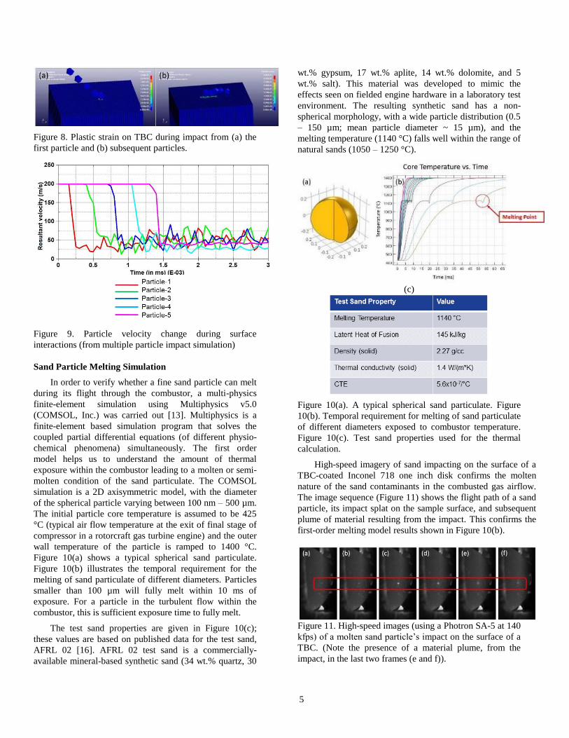
Figure 8. Plastic strain on TBC during impact from (a) the
first particle and (b) subsequent particles.
Figure 9. Particle velocity change during surface
interactions (from multiple particle impact simulation)
Sand Particle Melting Simulation
In order to verify whether a fine sand particle can melt
during its flight through the combustor, a multi-physics
finite-element simulation using Multiphysics v5.0
(COMSOL, Inc.) was carried out [13]. Multiphysics is a
finite-element based simulation program that solves the
coupled partial differential equations (of different physio-
chemical phenomena) simultaneously. The first order
model helps us to understand the amount of thermal
exposure within the combustor leading to a molten or semi-
molten condition of the sand particulate. The COMSOL
simulation is a 2D axisymmetric model, with the diameter
of the spherical particle varying between 100 nm – 500 µm.
The initial particle core temperature is assumed to be 425
°C (typical air flow temperature at the exit of final stage of
compressor in a rotorcraft gas turbine engine) and the outer
wall temperature of the particle is ramped to 1400 °C.
Figure 10(a) shows a typical spherical sand particulate.
Figure 10(b) illustrates the temporal requirement for the
melting of sand particulate of different diameters. Particles
smaller than 100 µm will fully melt within 10 ms of
exposure. For a particle in the turbulent flow within the
combustor, this is sufficient exposure time to fully melt.
The test sand properties are given in Figure 10(c);
these values are based on published data for the test sand,
AFRL 02 [16]. AFRL 02 test sand is a commercially-
available mineral-based synthetic sand (34 wt.% quartz, 30
wt.% gypsum, 17 wt.% aplite, 14 wt.% dolomite, and 5
wt.% salt). This material was developed to mimic the
effects seen on fielded engine hardware in a laboratory test
environment. The resulting synthetic sand has a non-
spherical morphology, with a wide particle distribution (0.5
– 150 µm; mean particle diameter ~ 15 µm), and the
melting temperature (1140 °C) falls well within the range of
natural sands (1050 – 1250 °C).
(c)
Figure 10(a). A typical spherical sand particulate. Figure
10(b). Temporal requirement for melting of sand particulate
of different diameters exposed to combustor temperature.
Figure 10(c). Test sand properties used for the thermal
calculation.
High-speed imagery of sand impacting on the surface of a
TBC-coated Inconel 718 one inch disk confirms the molten
nature of the sand contaminants in the combusted gas airflow.
The image sequence (Figure 11) shows the flight path of a sand
particle, its impact splat on the sample surface, and subsequent
plume of material resulting from the impact. This confirms the
first-order melting model results shown in Figure 10(b).
Figure 11. High-speed images (using a Photron SA-5 at 140
kfps) of a molten sand particle’s impact on the surface of a
TBC. (Note the presence of a material plume, from the
impact, in the last two frames (e and f)).

6
In addition, particle velocity measurements were carried
out using a Dantec two-component laser Doppler velocimetry
system during thermal cycling testing of coated samples with
sand ingestion using the hot particulate burner rig facility at
ARL (shown in Figure 14(b)). Molten sand particle velocity
measurements were obtained at the exit of the jet burner in the
center of the flame, and at a point close to the surface of a
coated Inconel circular disk sample in the flame. Figure 12(a)
shows the free stream impacting velocities of molten sand
particles, and Figure 12 (b) shows the rebound velocities of the
molten liquid sand particles close to the sample surface. From
these data, it is evident that most of the impacting molten sand
particles lose their kinetic energy resulting in deposition onto
the TBC surface.
Fig. 12(a). Two-component (U, V) free stream velocities of
molten sand particles (at burner exit)
Fig. 12(b). Two component (U, V) rebound velocities of
molten sand particles (close to sample surface)
Sand Particle Trajectory Simulations
In order to determine the vulnerable impact zones inside a
typical turbine nozzle passage, computational fluid dynamics
simulations were performed and then particle trajectory
simulations were carried out. From these simulations,
vulnerable zones of the blades where sand accumulation could
occur, were identified. The particle trajectory and wall
interactions were simulated using a fixed stator/rotor cascade
geometry as shown in Figure 13. The flow inlet conditions
studied were as follows, inflow velocity of 82.3 m/s,
temperature of 1400 °C, with pressure at 294 psi, and the
geometry was positioned sufficiently downstream and away
from boundaries as to avoid outflow numerical disturbances.
The concept model is based on earlier works using Eulerian-
Lagrangian particle injection methodology and it is coupled
with the surrounding carrier gas-phase turbulent environments
[21]. The flow turbulence is modeled via a Reynolds Average
Navier Stokes (RANS) approach and adaptive mesh refinement
(AMR) that resolves the flow field in local intensity regions
accurately and efficiently. At the blade surface, a law of the
wall model is utilized at a location of y+ = 50 to avoid the
excessive cost of resolving the viscous region. The surrogate
model assumes the sand particle is in the molten state, as it
leaves the combustion chamber, and prescribes molten silicon
dioxide (SiO2) physical transport properties.
Figure 13. Particle trajectories for a fixed stator/rotor cascade
(a) particulate flow and deposition dynamics, (b) streamwise
velocity distributions in realistic turbulent environment.
Figure 13 shows the sand ingestion and particle transport
around the three-dimension linear cascade geometry at the
(a)
(b)

7
operating engine condition. Particles that have sufficient kinetic
energy to deposit on the blade surface forming a film within the
regions of viscous flow near the wall. The simulations show a
higher rate of deposition on the stator row blades in comparison
to the rotor blades. In general, the particle deposition is higher
on the leading edge and the pressure surface as shown in Figure
13.
EXPERIMENTAL EFFORTS ARL spray technologies were used to tailor dissimilar
interfaces for densification of rigid particles during spray
deposition processes (SPD, SPPS, HVAF, HVOF and APS) to
generate the graded ceramic-metal and ceramic-composite
material to be characterized [22-24]. Simultaneous deposition
of ceramic and metallic materials can be achieved through the
use of two or more powder feeders [12]. Post-processing of
functionally-graded material (FGM) deposits via sintering and
HIPing can be used to remove any porosity, increase the density
and harden the outer ceramics for abrasion resistance. Coating
constituent materials were selected based on evaluations with
respect to thermal conductivity, phase stability, adhesion, strain
tolerance, impact/erosion resistance, and CMAS-interaction.
These coatings were deposited onto Inconel 718 one inch
circular disks using Air Plasma Spray (APS), Solution
Precursor Plasma Spray (SPPS), and Electron-Beam Physical
Vapor Deposition (EB-PVD). The coatings were then evaluated
using a high temperature button cell rig followed by a hot
burner rig facility at ARL (shown in Figure 14). Typically, the
coated samples were tested for three alternating thermal cycles
of 3 minutes each (hot/cold) with high temperature maintained
at 1300 °C (above sand melting point of 1140 °C) and at 1g/min
sand ingestion rate (AFRL 02 sand). AFRL 02 and AFRL 03
represent the state-of-the-art universal “average sand”
developed by AFRL for conducting standardized sand ingestion
tests for validation of gas turbine components’ resistance
against CMAS attack. AFRL 02 is generally comprised of
smaller grains and used for bench-level and component-level
testing. AFRL 03 exhibits larger grain distribution and is used
for engine-level testing. Based on material morphology data
after thermal cycling tests with sand particle ingestion, the
performances of the coatings were determined and ranked. In
addition to coating types, superfinishing of the coated surfaces
were considered in the selection process.
From the candidate coatings, the top 11 promising coatings
were selected and applied to 11 turbine nozzle doublets of a
typical high pressure turbine nozzle ring. This turbine nozzle
ring consisted of 12 nozzle doublets, with the remaining nozzle
doublet used as the baseline (Reference nozzle doublet) with
the coating as manufactured by the OEM. ARL-NASA and two
coating vendors supplied the selected 11 different
coatings/surface treatments for the eleven turbine nozzle
doublets, as listed in Table-1. The turbine nozzle ring with the
selected coatings applied is shown in Figure 15. The turbine
nozzle ring with the eleven candidate coatings was then
subjected to full engine test with mission relevant sand
ingestion using the AFRL03 sand. Figure 16 shows borescope
images of the nozzle vanes after the engine sand ingestion
testing.
(a) Button-cell flame rig (b) Jet Burner rig
Figure 14. Button-cell flame testing rig & hot particulate
ingestion jet burner rig.
Figure 15. Turbine nozzle ring with candidate coatings
Table-1. Coating compositions evaluated
8
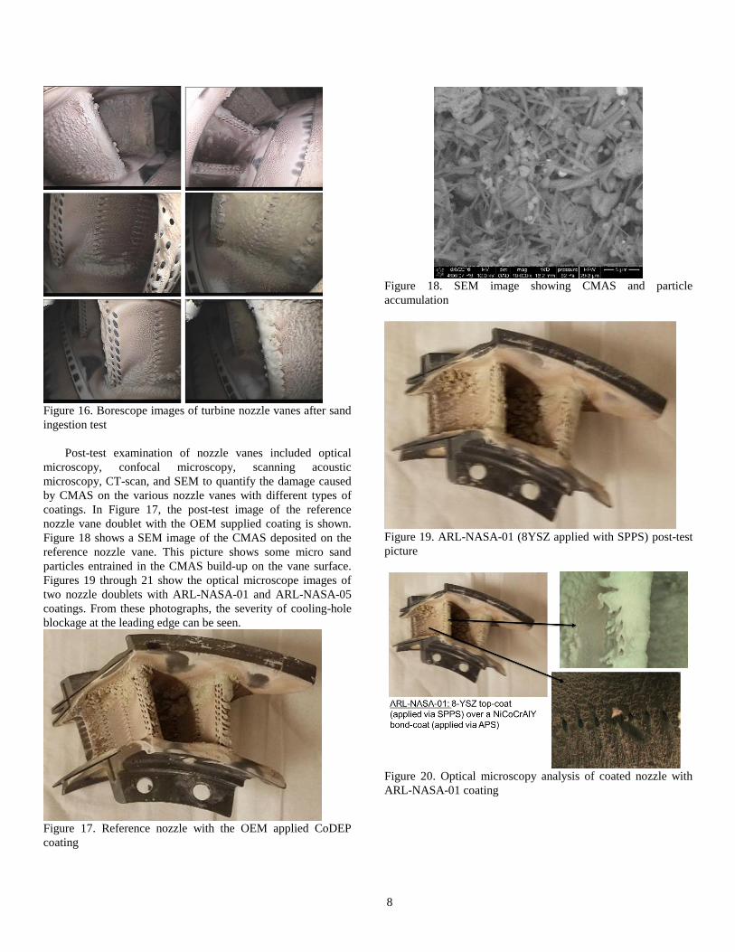
Figure 16. Borescope images of turbine nozzle vanes after sand
ingestion test
Post-test examination of nozzle vanes included optical
microscopy, confocal microscopy, scanning acoustic
microscopy, CT-scan, and SEM to quantify the damage caused
by CMAS on the various nozzle vanes with different types of
coatings. In Figure 17, the post-test image of the reference
nozzle vane doublet with the OEM supplied coating is shown.
Figure 18 shows a SEM image of the CMAS deposited on the
reference nozzle vane. This picture shows some micro sand
particles entrained in the CMAS build-up on the vane surface.
Figures 19 through 21 show the optical microscope images of
two nozzle doublets with ARL-NASA-01 and ARL-NASA-05
coatings. From these photographs, the severity of cooling-hole
blockage at the leading edge can be seen.
Figure 17. Reference nozzle with the OEM applied CoDEP
coating
Figure 18. SEM image showing CMAS and particle
accumulation
Figure 19. ARL-NASA-01 (8YSZ applied with SPPS) post-test
picture
Figure 20. Optical microscopy analysis of coated nozzle with
ARL-NASA-01 coating

9
Figure 21. Optical microscopy analysis of ARL-NASA-05
coating
Scanning Acoustic Microscopy Analysis
Scanning acoustic microscopy (SAM) analysis is a
technique that utilizes ultrasonic waves to non-destructively
characterize sub-surface defects present within a material
specimen or component. For the current study, the SAM was
operated in reflection mode to generate a C-Scan (horizontal
section), in which the elastic sound waves propagated onto the
sample by the transducer are reflected back when there is a
change in impedance, which is indicative of a change in
acoustic properties due to defects or material property changes.
The presence of CMAS was expected to generate an echo or
reflection due to the differences in composition, as well as the
relatively porous structure of the solidified CMAS.
Analysis of the post-test vanes was performed using a
Sonoscan Gen6 SAM, operated with a 15 MHz transducer and
deionized water as the transducing medium. Subsurface
imaging of the nozzle vanes was conducted by sequentially
gating the reflected echo (ultrasound signal reflected back by
sample) using a time interval of 1 µs. Sub-surface images of an
air-cleaned nozzle vanes (little to no CMAS present) and the
ARL-NASA-05 specimen are shown in Fig. 22. In the SAM
analysis presented in Fig. 22(a) and (b), the sample was
oriented so that the leading edges of the vanes were facing the
transducer, that is, the orientation of the images is the same as
that observed in the optical images in Fig. 17 and 21. Only one
sub-surface slice is presented here for brevity. It can be seen
that in addition to CMAS adhered on the outer walls, the sub-
surface air channel is also significantly clogged by sand. A
similar analysis was conducted with the pressure side of the
nozzle vanes oriented facing the transducer, as shown in Fig. 21
(c) and (d). Again, it can be seen that significant amounts of
sand are seen throughout the image, corresponding to sand
being present on both the surface and subsurface (i.e., cooling
channels) of the airfoil. The presence of CMAS on the exterior
and interior of nozzle vanes can have significant adverse effects
on the aerodynamic and thermal performance of the component.
The presence of sand within internal cooling channels indicates
that the bleed air used was substantially contaminated by the
sand laden flow.
Figure 22. Scanning acoustic microscopy (SAM) analysis of
nozzle vanes; a) and b) Sub-surface C-Scan of vane leading
edge for air cleaned vanes (a) and ARL-NASA-05 (b); c) and d)
C-Scan of vane pressure side for air cleaned vanes (c) and
ARL-NASA-05 vane (d).
CONCLUSION Sand ingestion is a serious problem for the high-
temperature turbine blades of commercial and military aircraft
and rotorcraft gas turbine engines. This paper reports the results
and findings from the on-going modeling and experimental
efforts that have been completed and currently underway on the
development of multi-functional, high-temperature thermal
barrier and sand-phobic coatings for future gas turbine
application at the U.S. Army Research Laboratory. The
following inferences are concluded from the current study:
Quantitative understanding of the underlying physio-
chemistry is lacking, but canonical simulations are
providing insight. Multiple particulate impacts cause
increasing plastic strain damage.
There is enough time for sand to fully melt while in the
combustor. Molten sand particulate rebound velocities
upon impact are nearly zero due to adhesion onto the TBC
surface.
Cooling-hole blockage has shown significant accumulation
and adhesion of CMAS on multi-layered coatings with
surface finish treatments.
Scanning acoustic microscopy analysis has made it evident
that the bleed air is substantially contaminated by fine sand
laden flow resulting in the presence of sand in the internal

10
micro-channels of nozzle vanes blocking the cooling flow.
Coating processes and surface finish are being studied for
reducing CMAS adherence and infiltration
Future research plans include:
o Continued morphology characterizations of the tested
tailored thermal barrier coatings, especially CT-scan
and cross-sectional SEM evaluations will be completed
in the near future.
o Based on learnings from current efforts, novel coatings
processes and surface finish treatments will be
developed for:
Layered TBC’s
Functionally gradient TBC’s
Integrated, functionally gradient CMC’s for
hot-section propulsion components (coating-
less blades)
o Advanced modeling/analysis capability to develop future
materials that effectively mitigate sand glazing and
CMAS formation.
ACKNOWLEDGMENTS The authors would like to thank and acknowledge the
efforts and inputs from Mr. Robert Dowding, Dr. Jacob Temme,
Mr. Richard Gerdom, Mr David Gondol, Mr. Mark Graybeal,
and Mr. William Gamble at U.S. Army Research Laboratory.
This research was sponsored by the U.S. Army Research
Laboratory, U.S. Naval Air Systems Command, and the U.S.
Army Aviation and Missile Research Development and
Engineering Center. Part of this work was accomplished under a
Cooperative Agreement with Oak Ridge Associated Universities
(W911NF-12-2-0019)
STANDARD DISCLAIMER
The views and conclusions contained in this document are
those of the authors and should not be interpreted as
representing the official policies or positions, either expressed
or implied, of the U.S. Army Research Laboratory, U.S. Naval
Air Systems Command, the U.S. Army Aviation and Missile
Research Development and Engineering Center or of the U.S.
Government.
REFERENCES [1] Smialek, J.L., Archer, F.A., and Garlick, R.G., “Turbine
Airfoil Degradation in the Persian Gulf War,” JOM, Vol.
46, 1994, pp. 39-41.
[2] Miller, R.A., “Current Status of Thermal Barrier Coatings –
An Overview,” Surface & Coatings Technology, Vol. 30,
1987, pp. 1-11.
[3]. Padture, N. P., Gell, M., and Jordan, E. H., “Thermal
Barrier Coatings for Gas-Turbine Engine Applications,”
Science, Vol. 296, 2002, pp. 280-284.
[4] Borom, M.P., Johnson, C.A., and Peluso, L.A., “Role of
Environment Deposits and Operating Surface Temperature
in Spallation of Air Plasma Sprayed Thermal Barrier
Coatings,” Surface & Coatings Technology, Vol. 86, 1996,
pp. 116-126.
[5] Levi, C.G., Hutchinson, J.W., Vidal-Setif, M.-H., and
Johnson, C.A., “Environmental Degradation of Thermal
Barrier Coatings by Molten Deposits,” MRS Bulletin, Vol.
37, 2012, pp. 932-941.
[6] Kramer, S., Yang, J., and Levi, C.G., “Infiltration-Inhibiting
Reaction of Gadolinium Zirconate Thermal Barrier
Coatings with CMAS Melts,” Journal of the American
Ceramic Society, Vol. 91, 2008, pp. 576-583.
[7] Rai, A.K., Bhattacharya, R.S., Wolfe, D.E., and Eden, T.J.,
“CMAS-Resistant Thermal Barrier Coatings,” International
Journal of Applied Ceramic Technology, Vol. 7, 2010, pp.
662-674.
[8] Aygun, A., Vasiliev, A.L., Padture, N.P., and Ma, X.,
“Novel Thermal Barrier Coatings that are Resistant to
High-Temperature Attack by Glassy Deposits,” Acta
Materialia, Vol. 55, 2007, pp. 6734-6745.
[9] Drexler, J.M., Shinoda, K., Ortiz, A.L., Li, D., Vasiliev,
A.L., Gledhill, A.D., Sampath, S., and Padture, N.P., “Air
Plasma-Sprayed Thermal Barrier Coatings that are
Resistant to High-Temperature Attack by Glassy Deposits,”
Acta Materialia, Vol. 58, 2010, pp. 6835-6844.
[10] Hutchinson, J.W., Evans, A.G., “On the Delamination of
Thermal Barrier Coatings in a Thermal Gradient”, Surface
and Coatings Technology, Vol. 149, 2002, pp. 179-184.
[11] Suresh, S. and Mortensen, A., “Functionally Graded
Metals and Metal-Ceramic Composites: Part 2
Thermomechanical Behaviour,” International Materials
Reviews, Vol. 42, 1997, pp. 85-116.
[12] Sampath, S., Herman, H. Shimoda, N., and Saito, T.,
“Thermal Spray Processing of FGMs,” MRS Bulletin, Vol.
20, 1995, pp. 27-31.
[13] Murugan, M., Ghoshal, A., Walock, M.J., Barnett, B.D.,
Pepi, M.S., Hopkins, D., Gazonas, G., Kerner, K.A.,
"Blade Surface-Particle Interaction and Multifunctional
Coatings for Gas Turbine Engine", 51st AIAA/SAE/ASEE
Joint Propulsion Conference, Propulsion and Energy
Forum, (AIAA 2015-4193).
[14] Schaedler, T., “Phase Evolution in the YO1.5-TiO2-ZrO2
System and Effects on Ionic Conductivity and Toughness,”
University of California-Santa Barbara, Santa Barbara, CA,
2006.
[15] LS-DYNA Keyword User’s Manual, Version 971, Volume
I, May 2007, Livermore Software Technology Corporation
(LSTC), Livermore, CA.
[16] Phelps, A. and Pfedderer, L., “Development of a
naturalistic test media for dust ingestion CMAS testing of
gas turbine engine,” in "Thermal Barrier Coatings IV", ECI
Symposium Series, (2015).
http://dc.engconfintl.org/thermal_barrier_iv/29
[17] Tabakoff, W., 1991, “Measurements of Particles Rebound
Characteristics on Materials used in Gas Turbines”, Journal
of Propulsion, Vol. 7, (5), 1991 pp. 805-813.

11
[18] Hamed, A., “Effect of Particle Characteristics on
Trajectories and Blade Impact Patterns”, Journal of Fluids
Engineering, Vol. 110, 1988, pp. 33-37.
[19] Murugan, D. M., Tabakoff, W., Hamed, A., “Computation
of Particle Restitution Characteristics Using DYNA3D for
Turbomachinery Application”, 30th AIAA/ASME/SAE
/ASEE Joint Propulsion Conference, Jun 27-29, 1994,
Indianapolis, Indiana.
[20] Tabakoff, W., Murugan, D. M., Hamed, A., “Effect of
Target Materials on the Particle Restitution Characteristics
for Turbomachinery Application”, 32nd Aerospace
Sciences Meeting & Exhibit, Jan 10-13, 1994, Reno,
Nevada.
[21] Bravo, L., Wijeyakulasuriya, S., Pomraning, E., Senecal,
P.K., Kweon, C.B., Large Eddy Simulation of High
Reynolds Number Nonreacting and Reacting JP-8 Sprays
in a Constant Pressure Flow Vessel With a Detailed
Chemistry Approach, Journal of Energy Resources
Technology, 138(3), 032207 (Mar 24, 2016), doi:
10.1115/1.4032901.
[22] Stöver, D., Pracht, G., Lehmann, H., Dietrich, M., Döring,
J-E., Vaβen, R. “New Material Concepts for the Next
Generation of Plasma-Sprayed Thermal Barrier Coatings”,
Journal of Thermal Spray Technology, Vol. 13, 2004, pp
76-83.
[23] Jordan, E.H., Xie, L., Ma, X., Gell, M., Padture, N.P.,
Cetegen, B., Ozturk, A., Roth, J., Xiao, T.D., Bryant,
P.E.C. “Superior Thermal Barrier Coatings Using Solution
Precursor Plasma Spray”, Journal of Thermal Spray
Technology, Vol 13, 2004, pp 57-65.
[24] Killinger, A., Gadow, R., Mauer, G., Guignard, A., Vaβen,
R., Stöver, D. “Review of New Developments in
Suspension and Solution Precursor Thermal Spray
Processes” Journal of Thermal Spray Technology, Vol. 20,
2011, pp 677-695.