gtu paper analysis chapter 1 introduction - darshan.ac.in paper...state and illustrate various...
TRANSCRIPT

GTU Paper Analysis
Design of Machine Elements (2151907) Department of Mechanical Engineering Darshan Institute of Engineering & Technology
Chapter 1 – Introduction
Sr. No. Questions
De
c –
15
Ma
y –
16
No
v –
16
Ma
y -
17
Theory
1. State and illustrate various principal design rules as per Casting Design with sketches. 07 05 07
2. State and illustrate various principle design rules used in design for forging. 07
3. Explain the designing for wear. 03
4. Design for creep. 03
5. Discuss the importance of selection of materials in machine design. 04 07
6. The series factor or geometric progression ratio for R10 series is (a) 1.26 (b) 1.12 (c) 1.58 (d) 1
01
7. Name the various alloying elements in ‘alloy’ steels. 03
8. What are the principles of design for manufacture and assemblies (DFMA)? 07
9. In which type of material Guest’s theory of failure is applicable? 01
Examples
1. What are preferred numbers? The maximum & minimum load carrying capacities of dumpers in a manufacturing unit are 630 KN and 40 KN respectively. The company is interested in developing seven models in this range. Specify their load carrying capacities.
05

GTU Paper Analysis
Design of Machine Elements (2151907) Department of Mechanical Engineering Darshan Institute of Engineering & Technology
Chapter 2 – Design Against Fluctuating Loads
Sr. No. Questions
De
c –
15
Ma
y –
16
No
v –
16
Ma
y –
17
Theory
1. Derive Soderberg’s equation and state its application to different types of loadings. 07 07
2. What is endurance strength? Discuss the factors affecting endurance strength of the materials. 04 07 03
3. Stress concentration factor is defined as ratio of (a) maximum stress to the endurance limit (b) nominal stress to the endurance limit (c) maximum stress to the nominal stress (d) nominal stress to the maximum stress
01
4. The endurance or fatigue limit is defined as the maximum value of the stress which a polished standard specimen can withstand without failure, for infinite number of cycles, when subjected to (a) static load (b) dynamic load (c) static as well as dynamic load (d) completely reversed load
01
5. What are the Goodman and the Soderberg line? 03
6. State the methods of reducing stress concentration. 04
7. Define Stress Concentration Factor. 01
8. What do you mean by Factor of Safety for Fatigue Loading? 01
9. Write Goodman formula for fluctuating stresses. 01
Examples
1.
The following data refers to a transmission shaft: Torsional moment that varies from = - 100 Nm to + 600 Nm. The Ultimate tensile strength = 630 MPa, Yield strength = 360 MPa, Stress load correction factor = 0.6, Size correction factor = 0.85, Surface finish factor = 0.8, Reliability factor = 0.897, Factor of safety = 2, Calculate the shaft diameter using distortion energy theory of failure.
07
2. A machine component is subjected to fluctuating stress that varies from 40 to 100 MPa. The corrected 07

GTU Paper Analysis
Design of Machine Elements (2151907) Department of Mechanical Engineering Darshan Institute of Engineering & Technology
endurance limit stress for the machine component is 270 MPa. The ultimate tensile strength and yield strength of material are 600 and 450 MPa respectively. Calculate the factor of safety using 1. Gerber theory, 2. Soderberg line and 3. Goodman line.
3.
A hot rolled steel shaft is subjected to a torsional moment that varies from 330 Nm to –110 Nm and an applied bending moment at a critical section varies from 440 Nm to –220 Nm. The shaft is of uniform cross-section and no keyway is present at the critical section. Determine the required shaft diameter. The material has an ultimate strength of 550 MPa and yield strength of 410 MPa. Take the endurance limit as half the ultimate strength, factor of safety of 2, size factor of 0.85 and a surface finish factor of 0.62.
07
4.
A cantilever beam made of carbon steel of circular cross-section as shown in figure, is subjected to a load which varies from –F to 3F. Determine the maximum load that the beam can sustain for an indefinite life. Factor of safety = 2, Stress concentration factor =1.42, Notch sensitivity = 0.9 Ultimate stress = 550 MPa, Yield stress = 470 MPa, Endurance limit = 275 MPa, Size factor = 0.85, Surface finish factor = 0.89 .
07
5.
A simply supported beam has a concentrated load at the centre which fluctuates from a value of ‘P’ to ‘4P’. The span of the beam is 500 mm and its cross-section is circular with a diameter of 60 mm. Taking for the beam material an ultimate stress of 700 MPa, a yield stress of 500 MPa, endurance limit of 330 MPa for reversed bending, and a factor of safety of 1.3, Calculate value of load ‘P’ based on Goodman’s formula. Take a size factor of 0.85 and a surface finish factor of 0.9.
07

GTU Paper Analysis
Design of Machine Elements (2151907) Department of Mechanical Engineering Darshan Institute of Engineering & Technology
Chapter 3 – Design of Springs
Sr. No. Questions
De
c –
15
Ma
y –
16
No
v –
16
Ma
y –
17
Theory
1. Explain buckling of spring in detail. 04
2. What is nipping in a leaf spring? Discuss its role. 04 04 04
3. Explain surge phenomenon in spring. 04 03 01
4. When a helical compression spring is subjected to an axial compressive load, the stress induced in the wire is (a) tensile stress (b) compressive stress (c) torsional shear stress (d) bending stress
01 01
5. In leaf springs, the longest leaf is known as (a) lower leaf (b) master leaf (c) upper leaf (d) none of these
01
6. What is shot peening? 03
7. Define Spring Rate. 01
8. Which type of spring is mostly used in Gramophone? 01
9. What is the function of a spring? In which type of springs the behavior is non-linear? 03
10. Explain the following terms of the spring: (1) Free Length (2) Spring Rate (3) Spring Index (4) Solid Height.
04
11. The extension springs are in considerably less use than the compression springs, why? 03
Examples
1. Design a helical compression spring from the following data: Minimum load = 100 N, Maximum load = 225.6 N, Compression of spring = 10 mm, Permissible shear stress for spring material = 440 MPa,
07

GTU Paper Analysis
Design of Machine Elements (2151907) Department of Mechanical Engineering Darshan Institute of Engineering & Technology
Spring end – square and ground ends, Modulus of rigidity for spring material = 0.80 x 10⁵ MPa.
2.
A semi-elliptic leaf spring consists of two extra full length leaves and eight graduated length leaves, including the master leaf. The center to center distance between the two eyes of the spring is 1 m. The maximum force acting on the spring is 10 kN and the width of the leaf is 50 mm. The spring is initially preloaded in such a way that when the load is maximum, the stresses induced in all the leaves are equal to 350 N/mm2. The modulus of elasticity of the leaf material is 2.07 x 10⁵ N/mm2. Determine: (i) The thickness of leaves. (ii) The deflection of the spring at maximum load.
07
3.
A helical compression spring made of oil tempered carbon steel is subjected to a fluctuating load from 400 N to 1000 N. The spring index is 6 and the design factor of safety is 1.25. If the yield stress in shear is 770 MPa and endurance stress in shear is 350 MPa, Find: 1. Size of the spring wire , 2. Diameters of the spring, 3. Number of turns of the spring, and 4. Free length of the spring. The compression of the spring at the maximum load is 30 mm. For spring material, the modulus of rigidity is 80 KN/mm2. Spring ends are square and ground.
07
4.
A semi-elliptical laminated vehicle spring to carry a load of 6000 N is to consist of seven leaves 65 mm wide, two of the leaves extending the full length of the spring. The spring is to be 1.1 m in length and attached to the axle by two U-bolts 80 mm apart. The bolts hold the central portion of the spring so rigidly that they may be considered equivalent to a band having a width equal to the distance between the bolts. Assume a design stress for spring material as 350 N/mm2. Determine: 1. Thickness of leaves 2. Deflection of spring 3. Diameter of eye 4. Length of leaves Take E = 210 KN/mm2, Bearing pressure = 8 N/mm2.
07
5.
The valve of an aircraft engine is operated by a cluster of two concentric springs made of same material. The maximum load on the spring is 6500 N. The permissible shear stress for the spring material is 625 N/mm2. Assuming spring index for both springs as 6 and the deflection under the load should not exceed 30 mm. Calculate the main dimensions of the springs. G = 8 ×10⁴ N/mm2. Use standard coil clearance.
07
6.
A semi-elliptical spring has ten leaves in all, with the two full length leaves extending 625 mm. It is 62.5 mm wide and is made of strips 6 mm thick. The leaves are pre-stressed so as to equalize stresses in all leaves. Design a helical spring, with spring index of 6, which will have approximately the same values of induced stress and deflection for any load. Take, E = 2.1 × 10⁵ MPa and G = 8.4 × 10⁴ MPa.
07
7. Design a helical compression spring for a maximum load of 1000 N for a deflection of 25 mm using the value of spring index as 5. The maximum permissible stress for spring wire is 420 N/mm2, and modulus of rigidity is 84 KN/ mm2.
07

GTU Paper Analysis
Design of Machine Elements (2151907) Department of Mechanical Engineering Darshan Institute of Engineering & Technology
8.
Design a leaf spring for following specification: Total load = 14 tonnes Numbers of springs supporting the load = 4 Maximum number of leaves = 10 Span of the spring = 1000 mm Permissible deflection = 80 mm Take Young Modulus = 0.2 x 10⁶ N/mm2, Allowable stress in spring material = 600 N/mm2
07
GTU Paper Analysis
Design of Machine Elements (2151907) Department of Mechanical Engineering Darshan Institute of Engineering & Technology
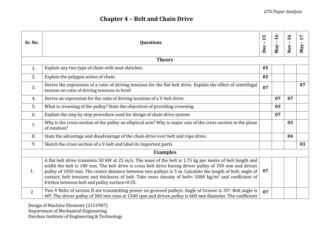
Chapter 4 – Belt and Chain Drive
Sr. No. Questions
De
c –
15
Ma
y –
16
No
v –
16
Ma
y -
17
Theory
1. Explain any two type of chain with neat sketches. 05
2. Explain the polygon action of chain. 02
3. Derive the expression of a ratio of driving tensions for the flat belt drive. Explain the effect of centrifugal tension on ratio of driving tensions in brief.
07 07
4. Derive an expression for the ratio of driving tensions of a V-belt drive. 07 07
5. What is crowning of the pulley? State the objectives of providing crowning. 03
6. Explain the step by step procedure used for design of chain drive system. 07
7. Why is the cross-section of the pulley an elliptical arm? Why is major axis of the cross-section in the plane of rotation?
03
8. State the advantage and disadvantage of the chain drive over belt and rope drive. 04
9. Sketch the cross section of a V-belt and label its important parts. 03
Examples
1.
A flat belt drive transmits 50 kW at 25 m/s. The mass of the belt is 1.75 kg per metre of belt length and width the belt is 180 mm. The belt drive is cross belt drive having driver pulley of 350 mm and driven pulley of 1050 mm. The centre distance between two pulleys is 5 m. Calculate the length of belt; angle of contact; belt tensions and thickness of belt. Take mass density of belt= 1000 kg/m3 and coefficient of friction between belt and pulley surface=0.35.
07
2 Two V Belts of section B are transmitting power on grooved pulleys. Angle of Groove is 350. Belt angle is 400. The driver pulley of 300 mm runs at 1500 rpm and driven pulley is 600 mm diameter. The coefficient
07
GTU Paper Analysis
Design of Machine Elements (2151907) Department of Mechanical Engineering Darshan Institute of Engineering & Technology
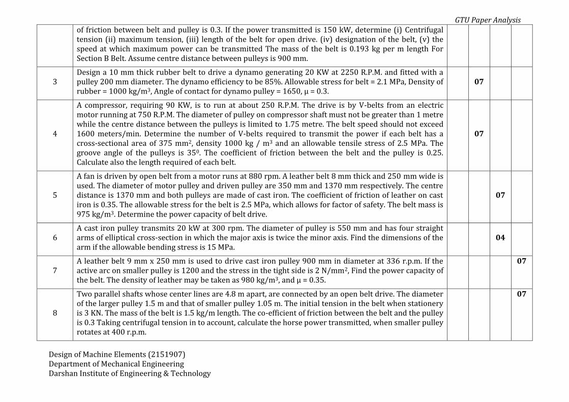
of friction between belt and pulley is 0.3. If the power transmitted is 150 kW, determine (i) Centrifugal tension (ii) maximum tension, (iii) length of the belt for open drive. (iv) designation of the belt, (v) the speed at which maximum power can be transmitted The mass of the belt is 0.193 kg per m length For Section B Belt. Assume centre distance between pulleys is 900 mm.
3 Design a 10 mm thick rubber belt to drive a dynamo generating 20 KW at 2250 R.P.M. and fitted with a pulley 200 mm diameter. The dynamo efficiency to be 85%. Allowable stress for belt = 2.1 MPa, Density of rubber = 1000 kg/m3, Angle of contact for dynamo pulley = 1650, µ = 0.3.
07
4
A compressor, requiring 90 KW, is to run at about 250 R.P.M. The drive is by V-belts from an electric motor running at 750 R.P.M. The diameter of pulley on compressor shaft must not be greater than 1 metre while the centre distance between the pulleys is limited to 1.75 metre. The belt speed should not exceed 1600 meters/min. Determine the number of V-belts required to transmit the power if each belt has a cross-sectional area of 375 mm2, density 1000 kg / m3 and an allowable tensile stress of 2.5 MPa. The groove angle of the pulleys is 350. The coefficient of friction between the belt and the pulley is 0.25. Calculate also the length required of each belt.
07
5
A fan is driven by open belt from a motor runs at 880 rpm. A leather belt 8 mm thick and 250 mm wide is used. The diameter of motor pulley and driven pulley are 350 mm and 1370 mm respectively. The centre distance is 1370 mm and both pulleys are made of cast iron. The coefficient of friction of leather on cast iron is 0.35. The allowable stress for the belt is 2.5 MPa, which allows for factor of safety. The belt mass is 975 kg/m3. Determine the power capacity of belt drive.
07
6 A cast iron pulley transmits 20 kW at 300 rpm. The diameter of pulley is 550 mm and has four straight arms of elliptical cross-section in which the major axis is twice the minor axis. Find the dimensions of the arm if the allowable bending stress is 15 MPa.
04
7 A leather belt 9 mm x 250 mm is used to drive cast iron pulley 900 mm in diameter at 336 r.p.m. If the active arc on smaller pulley is 1200 and the stress in the tight side is 2 N/mm2, Find the power capacity of the belt. The density of leather may be taken as 980 kg/m3, and µ = 0.35.
07
8
Two parallel shafts whose center lines are 4.8 m apart, are connected by an open belt drive. The diameter of the larger pulley 1.5 m and that of smaller pulley 1.05 m. The initial tension in the belt when stationery is 3 KN. The mass of the belt is 1.5 kg/m length. The co-efficient of friction between the belt and the pulley is 0.3 Taking centrifugal tension in to account, calculate the horse power transmitted, when smaller pulley rotates at 400 r.p.m.
07
GTU Paper Analysis
Design of Machine Elements (2151907) Department of Mechanical Engineering Darshan Institute of Engineering & Technology
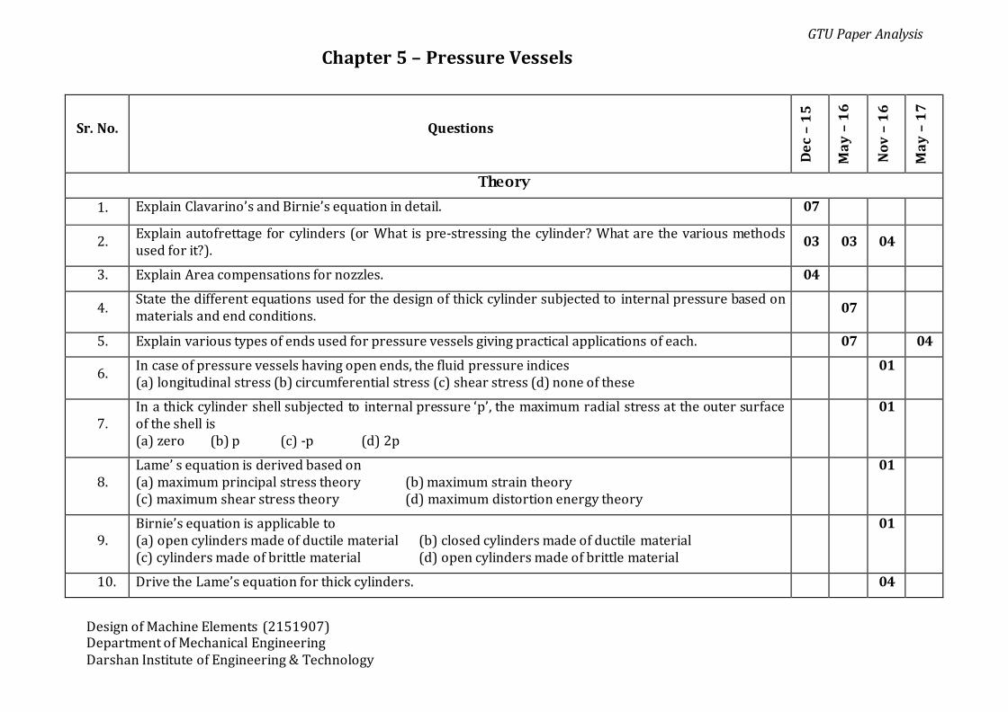
Chapter 5 – Pressure Vessels
Sr. No. Questions
De
c –
15
Ma
y –
16
No
v –
16
Ma
y –
17
Theory
1. Explain Clavarino’s and Birnie’s equation in detail. 07
2. Explain autofrettage for cylinders (or What is pre-stressing the cylinder? What are the various methods used for it?).
03 03 04
3. Explain Area compensations for nozzles. 04
4. State the different equations used for the design of thick cylinder subjected to internal pressure based on materials and end conditions.
07
5. Explain various types of ends used for pressure vessels giving practical applications of each. 07 04
6. In case of pressure vessels having open ends, the fluid pressure indices (a) longitudinal stress (b) circumferential stress (c) shear stress (d) none of these
01
7. In a thick cylinder shell subjected to internal pressure ‘p’, the maximum radial stress at the outer surface of the shell is (a) zero (b) p (c) -p (d) 2p
01
8. Lame’ s equation is derived based on (a) maximum principal stress theory (b) maximum strain theory (c) maximum shear stress theory (d) maximum distortion energy theory
01
9. Birnie’s equation is applicable to (a) open cylinders made of ductile material (b) closed cylinders made of ductile material (c) cylinders made of brittle material (d) open cylinders made of brittle material
01
10. Drive the Lame’s equation for thick cylinders. 04
GTU Paper Analysis
Design of Machine Elements (2151907) Department of Mechanical Engineering Darshan Institute of Engineering & Technology
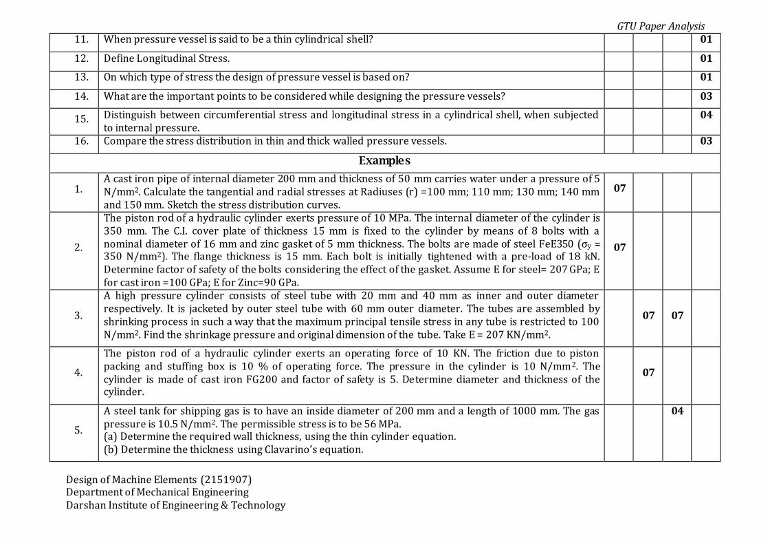
11. When pressure vessel is said to be a thin cylindrical shell? 01
12. Define Longitudinal Stress. 01
13. On which type of stress the design of pressure vessel is based on? 01
14. What are the important points to be considered while designing the pressure vessels? 03
15. Distinguish between circumferential stress and longitudinal stress in a cylindrical shell, when subjected to internal pressure.
04
16. Compare the stress distribution in thin and thick walled pressure vessels. 03
Examples
1. A cast iron pipe of internal diameter 200 mm and thickness of 50 mm carries water under a pressure of 5 N/mm2. Calculate the tangential and radial stresses at Radiuses (r) =100 mm; 110 mm; 130 mm; 140 mm and 150 mm. Sketch the stress distribution curves.
07
2.
The piston rod of a hydraulic cylinder exerts pressure of 10 MPa. The internal diameter of the cylinder is 350 mm. The C.I. cover plate of thickness 15 mm is fixed to the cylinder by means of 8 bolts with a nominal diameter of 16 mm and zinc gasket of 5 mm thickness. The bolts are made of steel FeE350 (σy = 350 N/mm2). The flange thickness is 15 mm. Each bolt is initially tightened with a pre-load of 18 kN. Determine factor of safety of the bolts considering the effect of the gasket. Assume E for steel= 207 GPa; E for cast iron =100 GPa; E for Zinc=90 GPa.
07
3.
A high pressure cylinder consists of steel tube with 20 mm and 40 mm as inner and outer diameter respectively. It is jacketed by outer steel tube with 60 mm outer diameter. The tubes are assembled by shrinking process in such a way that the maximum principal tensile stress in any tube is restricted to 100 N/mm2. Find the shrinkage pressure and original dimension of the tube. Take E = 207 KN/mm2.
07 07
4.
The piston rod of a hydraulic cylinder exerts an operating force of 10 KN. The friction due to piston packing and stuffing box is 10 % of operating force. The pressure in the cylinder is 10 N/mm2. The cylinder is made of cast iron FG200 and factor of safety is 5. Determine diameter and thickness of the cylinder.
07
5.
A steel tank for shipping gas is to have an inside diameter of 200 mm and a length of 1000 mm. The gas pressure is 10.5 N/mm2. The permissible stress is to be 56 MPa. (a) Determine the required wall thickness, using the thin cylinder equation. (b) Determine the thickness using Clavarino’s equation.
04

GTU Paper Analysis
Design of Machine Elements (2151907) Department of Mechanical Engineering Darshan Institute of Engineering & Technology
6. A thick cylinder having 120 mm external diameter and 60 mm internal diameter is subjected to an internal fluid pressure of 15 MPa and external fluid pressure of 6 MPa. Determine the resultant hoop and radial stresses at inner and outer surface of cylinder. Also sketch curves showing the stresses distribution.
07
7.
An accumulator is required to store 150 liters of water at a pressure 20 MPa. Assuming the length of stroke to be 3 meter, determine: (a) The diameter of the ram. (b) The internal diameter of the cylinder, assuming a clearance of 40 mm. (c) The thickness of the cylinder, if the permissible stress of the cylinder (made of CI) is 60 N/mm2.
03
8.
A shrink fit assembly formed by shrinking one tube over another, is subjected to an internal pressure of 60 N/mm2. Before the fluid is admitted, the internal and the external diameters of the assembly are 120 mm and 200 mm and the diameter of the junction is 160 mm. If after shrinking on, the contact pressure at the junction is 8 N/mm2, Determine using Lame’s equations, stresses at the inner, mating and outer surfaces of the assembly after the fluid has been admitted.
07