guidance for implementing a risk …nfpa805.com/nei/nei_04-02_ r2 ml0608800500.pdf · 2.3.3...
TRANSCRIPT

NEI 04-02
REVISION 2 NUCLEAR ENERGY INSTITUTE
GUIDANCE FOR IMPLEMENTING
A RISK-INFORMED, PERFORMANCE-BASED
FIRE PROTECTION PROGRAM
UNDER 10 CFR 50.48(c)
February 2006

Revision 1 i
ACKNOWLEDGEMENTS The Nuclear Energy Institute (NEI), Kleinsorg Group Risk Services, LLC; Ratchford Diversified Services, LLC; Erin Engineering and Research, Inc.; Law Offices of Sheldon Trubatch; Hughes Associates, Inc.; and Triad Fire Protection Engineering, recognize the following individuals for their contribution to this project. Their time, effort, and valuable input contributed significantly to the project.
Harry Barrett Duke Power Douglas Brandes Duke Power William Burns Southern Nuclear Jeff Ertman Progress Energy Tom Furlong NEIL Steve Hardy Progress Energy Dennis Henneke Duke Power Alan Holder Entergy Robert Kassawara EPRI Bob Richter Southern California Edison Ron Rispoli Entergy Cliff Sinopoli Exelon Denis Shumaker Public Service Electric and Gas
NOTICE Neither the Nuclear Energy Institute, nor any of its employees, members, supporting organizations, contractors or consultants make any warranty, expressed or implied, or assume any legal responsibility for the accuracy or completeness of, or assume any liability for damages resulting from any use of, any information apparatus, method, or process disclosed in this report or that such may not infringe privately owned rights.

Revision 1 ii
EXECUTIVE SUMMARY On July 16, 2004 the Nuclear Regulatory Commission amended 10 CFR Part 50.48 “Fire Protection” to add a new subsection, 10 CFR 50.48(c), that established acceptable fire protection requirements. The change to 10 CFR 50.48 endorses, with exceptions, the National Fire Protection Association’s 805, “Performance-Based Standard for Fire Protection for Light Water Reactor Electric Generating Plants – 2001 Edition,” as a voluntary alternative for demonstrating compliance with 10 CFR 50.48 Section (b) and Section (f). This document provides guidance for implementing the requirements of this rule change, and to the degree endorsed by the NRC, represents methods acceptable to the NRC for implementing in whole or in part a risk-informed, performance-based fire protection program.

Revision 1 iii
TABLE OF CONTENTS
1.0 INTRODUCTION ..................................................................................................................1
1.1 Background.......................................................................................................................1
1.2 Purpose and Scope ............................................................................................................2
1.3 Relationship with Other Rules, Regulatory Guidance, Standards, and Programs ............3
1.4 Responsibilities and Qualifications...................................................................................5
1.4.1 Responsibilities ........................................................................................................5 1.4.2 Qualifications...........................................................................................................5
1.5 Applicability .....................................................................................................................5
2.0 REGULATORY FRAMEWORK ..........................................................................................6
2.1 Introduction.......................................................................................................................6
2.2 Overview of the Rule ........................................................................................................6
2.2.1 Incorporation by Reference......................................................................................7 2.2.2 Relationship to Other Fire Protection Requirements ...............................................8 2.2.3 Alternative Requirements in the New Rule .............................................................8
2.3 Demonstration of Compliance with the New Requirements ............................................8
2.3.1 Previous Approval Determination ...........................................................................9 2.3.2 Improper Determination of Previous NRC Approval............................................10 2.3.3 Non-compliance with the Current Fire Protection Licensing Basis ......................10
2.4 Alternate Methods and Approaches................................................................................12
2.4.1 Plant Specific License Amendment .......................................................................12 2.4.2 License Amendment Supported by Topical Report...............................................13
3.0 RISK-INFORMED, PERFORMANCE-BASED FIRE PROTECTION PROCESS ...........13
3.1 Process Summary............................................................................................................13
3.2 NFPA 805 Process ..........................................................................................................14
3.3 Overall Process for Implementing a New Licensing Basis ............................................16
3.4 Licensee Transition Documentation Overview ..............................................................18
3.5 Compliance During the Transition Period ......................................................................19
4.0 TRANSITION FOR ADOPTION OF A NEW LICENSING BASIS..................................20
4.1 Transition - Introduction.................................................................................................20
4.1.1 Transition Process Overview .................................................................................20 4.1.2 The Three Phases of the Transition Timeline ........................................................22
4.2 Preliminary Assessment..................................................................................................23

Revision 1 iv
4.2.1 Technical and Regulatory Assessment ..................................................................23 4.2.2 Transition Letter of Intent......................................................................................24
4.3 Reviews and Engineering Analyses................................................................................24
4.3.1 Fundamental Fire Protection Program and Design Elements Transition Review .25 4.3.2 Nuclear Safety Performance Criteria Transition Review ......................................27 4.3.3 Non-Power Operational Modes Transition Review...............................................29 4.3.4 Radioactive Release Transition Review ................................................................30
4.4 Licensing Basis Transition - Change Evaluations ..........................................................31
4.5 Licensing Basis Transition - Program Documentation and Maintenance ......................32
4.5.1 Program Documentation and Quality Assurance...................................................32 4.5.2 Configuration Control............................................................................................32 4.5.3 Monitoring .............................................................................................................32
4.6 Regulatory Submittal and Transition Documentation ....................................................33
4.6.1 License Amendment Request ................................................................................33 4.6.2 Transition Report ...................................................................................................35
5.0 PROGRAM MAINTENANCE AND CONFIGURATION CONTROL.............................36
5.1 Program Documentation, Configuration Control, and Quality Assurance .....................36
5.1.1 General Guidance for Program Documentation ....................................................36 5.1.2 Fire Modeling Considerations................................................................................38 5.1.3 Fire PRA Considerations .......................................................................................39
5.2 Monitoring ......................................................................................................................39
5.2.1 Existing Guidance and Programs...........................................................................40 5.2.2 Monitoring Program Development ........................................................................40 5.2.3 Monitoring Considerations ....................................................................................41
5.3 Plant Change Process......................................................................................................42
5.3.1 Overview................................................................................................................42 5.3.2 Defining the Change ..............................................................................................45 5.3.3 Preliminary Risk Screening ...................................................................................49 5.3.4 Risk Evaluation......................................................................................................50 5.3.5 Acceptance Criteria................................................................................................51
6.0 IMPLEMENTING GUIDANCE FOR USE OF TOOLS AND PROCESSES WITHIN EXISTING LICENSING BASIS..........................................................................................58
6.1 Applicability of the program change process in NFPA 805 ...........................................58
6.2 Application of the Plant Change Evaluation Process .....................................................59
6.2.1 Identify the Change from the Current Fire Protection Licensing Basis.................59 6.2.2 Conduct an Initial Assessment...............................................................................59 6.2.3 Conduct a Fire Risk Analysis to Show that the Acceptance Criteria are Met .......60
6.3 Requests for Regulatory Relief.......................................................................................60
Deleted: 57
Deleted: 57
Deleted: 58
Deleted: 58
Deleted: 58
Deleted: 59
Deleted: 59

Revision 1 v
6.4 NRC Review and Approval ............................................................................................60
7.0 REFERENCES .....................................................................................................................61
Appendices.....................................................................................................................................63 A. Definitions.................................................................................................................... A-1 B. Detailed Transition Assessment of Fire Protection Program....................................... B-1 C. Fire Protection Program Design / Licensing Document Post Transition..................... C-1 D. Fire Modeling............................................................................................................... D-1 E. Monitoring ....................................................................................................................E-1 F. Considerations for Non-Power Operational Modes......................................................F-1 G. Considerations for Radioactive Release ...................................................................... G-1 H. Regulatory Submittal & Transition Documentation .................................................... H-1 I. Plant Change Evaluation Form ......................................................................................I-1 J. Plant Change Evaluations ..............................................................................................J-1
Deleted: 59
Deleted: 60
Deleted: 62

Revision 1 1
1.0 INTRODUCTION On July 16, 2004 the Nuclear Regulatory Commission (NRC) amended 10 CFR Part 50.48 “Fire protection” to add a new subsection, 10 CFR 50.48(c), that established fire protection requirements (69 FR 33536). The change to 10 CFR 50.48 endorses with exceptions the National Fire Protection Association’s (NFPA) 805, “Performance-Based Standard for Fire Protection for Light Water Reactor Electric Generating Plants – 2001 Edition,” as a voluntary alternative for demonstrating compliance with 10 CFR 50.48 Section (b) and Section (f)1. This document provides guidance for implementing the requirements of this rule change, and to the degree endorsed by the NRC, represents methods acceptable to the NRC for implementing in whole or in part a risk-informed, performance-based fire protection program. Definitions used in this document are contained in Appendix A of this document.
1.1 Background Fire protection requirements predating the July 16, 2004 Amendment to 10 CFR 50.48 are prescriptive in nature and were established well before the emergence of risk-informed, performance-based analytical techniques. Consequently, the prescriptive requirements do not include the benefits of probabilistic risk assessments (PRAs) for fires, nor do they reflect insights into fire risk evident from the significant body of operating experience developed through risk-based assessments. As PRA technology developed and additional operating experience was accumulated, the NRC, in SECY-93-143, “Report on the Re-assessment of the NRC Fire Protection Program,” determined that the situation had changed sufficiently to support a recommendation for a revised 10 CFR 50.48 that would take risk concepts into account. In addition, as discussed in SECY-96-134, “Options for Pursuing Regulatory Improvement in Fire Protection Regulations of Nuclear Power Plants,” dated June 21, 1996, a revised fire protection rule that would allow flexibility and facilitate the use of alternate approaches to meet the fire safety objectives may reduce the need for exemptions. The NRC in SECY-98-058, “Development Of A Risk-Informed, Performance-Based Regulation for Fire Protection at Nuclear Power Plants,” assessed options for developing a new risk-informed, performance-based fire protection regulation. In it, the NRC staff recommended that NRC be authorized to work with NFPA on the development of a risk-informed, performance-based standard for nuclear plant fire protection. They further recommend that rulemaking to adopt the standard and a regulatory guide to interpret the standard is initiated following issuance of the standard. As discussed in SECY-98-058, the NRC’s adoption of NFPA 805 was considered consistent with the Commission’s policy specified in Direction Setting Issue (DSI) 13, “The Role of Industry”; Office of Management and Budget Circular A-119, “Federal Participation in the Development and Use of Voluntary Consensus Standards and in Conformity Assessment Activities”; and Public Law 104-113, “National Technology Transfer Act of 1995.” These guidance documents encourage the U.S. Government’s adoption of national consensus standards to carry out its policy objectives and activities.
1 All references made to NFPA 805 are to the 2001 edition.

Revision 1 2
NEI, representing the nuclear industry, is a proponent of the use of risk-informed, performance-based processes. NEI has worked to ensure that the adoption of a new fire protection licensing basis is optional, and not a requirement. NEI has also worked to ensure that the process of adoption of a new fire protection licensing basis is effective and comprehensive, without placing an unnecessary burden on licensees pursuing risk-informed, performance-based initiatives. Subsequently, NFPA 805 was developed to provide a comprehensive risk-informed, performance-based standard for fire protection. The NFPA 805 Technical Committee on Nuclear Facilities is comprised of nuclear plant licensees, the NRC, insurers, equipment manufacturers, and subject matter experts. The standard was developed in accordance with NFPA processes, and consisted of a number of technical meetings and reviews of draft documents by committee and industry representatives. The scope of NFPA 805 includes goals related to nuclear safety, radioactive release, life safety, and plant damage/business interruption. The standard addresses fire protection requirements for nuclear plants during all plant operating modes and conditions, including shutdown and decommissioning, which had not been explicitly addressed by previous requirements and guidelines. NFPA 805 became effective on February 9, 2001. Although NFPA 805 provides many of the tools and processes necessary for risk-informed, performance-based fire protection, additional guidance and clarification is warranted. This implementing guidance is intended to provide that additional guidance and clarification.
1.2 Purpose and Scope This implementing guidance for NFPA 805 has two primary purposes:
Provide direction and clarification for adopting NFPA 805 as an acceptable approach to fire protection, consistent with 10 CFR 50.48 (c), and
Provide additional supplemental technical guidance and methods for using NFPA 805 and its appendices to demonstrate compliance with fire protection requirements.
NFPA 805 establishes a comprehensive set of requirements for fire protection programs at nuclear power plants. It incorporates both deterministic and risk-informed, performance-based concepts. The deterministic aspects of NFPA 805 are comparable to traditional requirements, and thus need little additional guidance. Although there is a significant amount of detail in NFPA 805 and its appendices, clarification and additional guidance for select issues will help ensure consistency and effective utilization of the standard. Accordingly, this implementing guidance focuses attention on the risk-informed, performance-based fire protection goals, objectives, and performance criteria contained in NFPA 805 and the risk-informed, performance-based tools considered acceptable for demonstrating compliance. NFPA 805 addresses primarily technical issues and does not provide a framework or guidance pertaining to the regulatory processes for adopting NFPA 805 as a new licensing basis. This document provides that framework and detailed guidance for transitioning to a risk-informed, performance-based licensing basis. NFPA 805 also does not address use of the analytical tools and processes within an existing licensing basis. The rule does not approve the use of NFPA 805 methods and analytical approaches for purposes other than demonstrating compliance with NFPA 805, any other use of those methods and analytical approaches requires the necessary NRC approvals under 10 CFR

Revision 1 3
50.90, 10 CFR 50.12, or other applicable regulations. This implementing guidance addresses these regulatory process matters in Chapter 6. The scope of the implementing guidance includes:
Chapter 2 - Discussion of the regulatory framework for adopting NFPA 805 as the basis for compliance to fire protection regulations;
Chapter 3 - Overview of the risk-informed, performance-based fire protection program process and available options;
Chapter 4 - Implementing guidance for transitioning from a pre-transition fire protection licensing basis (Appendix R / NUREG-0800) to a new NFPA 805 fire protection licensing basis;
Chapter 5 - Guidance for program maintenance and configuration control processes; and
Chapter 6 - Guidance for using NFPA 805 analysis tools within a current licensing basis (CLB).
This implementing guidance addresses only those elements of NFPA 805 that are within the scope of the NRC’s jurisdiction under 10 CFR 50.48. The goals of Life Safety and Plant Damage/Business Interruption within NFPA 805 and its appendices are outside of the scope of 10 CFR 50.48 and thus are not addressed in this guidance.
1.3 Relationship with Other Rules, Regulatory Guidance, Standards, and Programs
10 CFR 50.48 and 10 CFR 50, Appendix R - refer to Section 2.0 of this document.
NEI 00-01 Revision 1 – NEI 00-01 contains the preferred methods of demonstrating compliance with certain aspects of NFPA 805. NEI 00-01 as endorsed by the NRC
Regulatory Guide 1.189, NUREG 0800 Standard Review Plan Section 9.5.1 with Branch Technical Position CMEB 9.5-1, Branch Technical Position (BTP) APCSB 9.5-1, and Appendix A to APCSB 9.5-1 – These documents contain acceptable methods of demonstrating compliance with NRC Fire Protection Regulations. Licensees should refer to their plant-specific licensing bases to determine the applicability of specific guidance to a specific plant. Licensee’s commitments to these documents will be used as input into the transition process. See Section 4.3.1 of this document.
10 CFR 50.59 and NEI 96-07 Revision 1 - 10CFR 50.59 establishes the conditions under which licensees may make changes to the facility or procedures and conduct tests or experiments without prior NRC approval. NEI 96-07 provides guidance for developing an effective and consistent 10 CFR 50.59 implementation processes. If a licensee adopts the NFPA 805 licensing basis, the NFPA 805 change process is an acceptable method of evaluating fire protection program changes. NEI 02-03 – “Guidance for Performing a Regulatory Review of Proposed Changes to the Approved Fire Protection Program,” – provides a framework for making such changes to the fire protection program. See Section 5.3 of this document.
Deleted: utility

Revision 1 4
10 CFR 50.69 “Risk-informed categorization and treatment of structures, systems and components for nuclear power reactors" - Allows certain SSCs to be treated in a risk informed manner. 10 CFR 50.69 is not applicable to 10 CFR 50.48 "Fire protection" since 50.48 is not included in Section (b) of 50.69. 10 CFR 50.48(c) allows the voluntary application of a performance-based fire protection rule. The treatment of SSCs under 10 CFR 50.48(c) shall be in accordance with the rule, the referenced NFPA standard, and the applicable licensee's licensing basis.
10 CFR 50.72 and 10 CFR 50.73 - The process to implement these regulations remain unchanged as a result of adopting 10 CFR 50.48(c).
Reactor Oversight Process/Significance Determination process – Although this process would not change if a plant chooses to adopt the NFPA 805 regulation, the conditions for entry into the process would change because the types of non-compliances would be different, as illustrated by the modifications to terminology (safe shutdown versus nuclear safety, etc.) that may be required.
10 CFR 50.65 and NUMARC 93-01 - Maintenance Rule – the technique(s) used in the maintenance rule program may be used in the “monitoring” program described in NFPA 805. See Section 5.2 of this document.
Corrective Action Program - This process would not change if a plant chooses to adopt 10 CFR 50.48(c). However, priorities for taking corrective actions might change consistent with the modifications to terminology (safe shutdown versus nuclear safety, etc.).
NUMARC 91-06 (Shutdown) and NUREG-1449 - These documents provide input to the evaluation of non-power modes of operation. See Appendix F.
NEI Document NUMARC 93-01, Industry Guideline for Monitoring the Effectiveness of Maintenance at Nuclear Power Plants – This document provides an acceptable approach to meet the Maintenance Rule. See Section 5.2 of this document.
Generic Letter 91-18, Rev.1 – This document discusses guidance for compensatory actions during temporary non-compliances. This process would not change if a plant chooses to adopt the 10 CFR 50.48(c). However, its use during the transition period (See Section 4.0) may be modified. In addition, modifications to terminology (safe shutdown versus nuclear safety, etc.) may be required.
RIS 2000-17 adopting NEI 99-04 – This document discusses how licensees can modify regulatory commitments. This process would not change if a plant chooses to adopt 10 CFR 50.48(c); however, the change process (See Section 5.3 of this document) provides more specific detail of when a plant change process would change for the fire protection program.
Regulatory Guide 1.174 – This document contains guidance on the acceptance criteria for changes in risk that may result from a plant change. The guidance ensures that only small increases in risk are allowed and encourages plant changes that result in either no change in risk or a reduction in risk.

Revision 1 5
1.4 Responsibilities and Qualifications
1.4.1 Responsibilities Licensees adopting 10 CFR 50.48 (c) should use this guidance to assist in developing and maintaining plant-specific risk-informed, performance-based programs. Other licensees may use the processes and techniques in this guidance within a CLB. Responsibilities associated with establishing and maintaining a fire protection plan are delineated in Section 3.2 of NFPA 805.
1.4.2 Qualifications Qualifications for individuals responsible for administration of a fire protection program are discussed in Section 3.2 and Appendix A of NFPA 805. This includes recommendations that individuals responsible for day-to-day administration of the fire protection programs be experienced in nuclear power plant fire protection, preferably with qualifications consistent with member grade status in the Society of Fire Protection Engineers. Due to the technical nature of risk-informed, performance-based fire protection analyses, additional minimum qualifications are recommended for individuals practicing fire modeling and quantitative fire protection risk assessments.
1.4.2.1 Fire Modeling The qualifications necessary for personnel involved in the fire modeling projects depends to a great extent on their role, and the nature of the analysis. In general, the individual responsible for conducting quantitative engineering analysis related to fire hazard quantification should be an experienced engineer with formal training in fire dynamics and use of the methods or models being used. The user should also have knowledge of available data sources and validation studies for the method being used. In addition to modeling and analysis expertise, the successful application of modeling will involve an individual or team with experience in NPP systems and plant operations, all relevant regulations, plant configurations and QA/QC programs. For simple calculations where well defined and isolated fuel arrays are being evaluated and less expertise is required, an engineer with training in the calculation methods being used is adequate.
1.4.2.2 Fire Risk Assessment The qualifications necessary of personnel involved in quantitative fire risk assessment (i.e., Fire PRA) should be consistent with that applicable to individuals performing PRA studies. In general, the individual responsible for PRA should be an experienced engineer with formal training in PRA and fire PRA. As such, the licensee should apply the same training and/or qualification standard to individuals conducting fire risk assessments. Individuals should also have experience in fire risk assessments, such as involvement in an Individual Plant Examination for External Events (IPEEE) effort.
1.5 Applicability As stated in 10 CFR 50.48 (c)(3)(i), any licensee’s adoption of a risk-informed, performance-based program that complies with the rule is voluntary. Compliance with this rule may be adopted as an acceptable alternative method for complying with either 10 CFR 50.48 (b), for plant licensed to operate before January 1, 1979, or the fire protection license conditions for

Revision 1 6
plants licensed to operate after January 1, 1979, or 10 CFR 50.48 (f), plants shutdown in accordance with 10 CFR 50.82(a)(1). Accordingly, the use of this guidance is also voluntary.2 For the purpose of this document the terms Current Licensing Basis (CLB) or pre-transitional fire protection licensing basis” will be used and will apply equally to plants licensed to 10 CFR 50.48, Appendix R or NUREG-0800. The term “NFPA 805 licensing basis” will be used to describe plant licensing bases that use NFPA 805 and the new risk-informed, performance-based program.
2.0 REGULATORY FRAMEWORK
2.1 Introduction The NRC has adopted NFPA 805, with a few specific exceptions, as an alternative, risk-informed, performance-based regulation for fire protection at nuclear power plants. Licensees may continue to comply with the current fire protection requirements or voluntarily transition to the new requirements (“NFPA 805 licensing basis”). This Section describes the regulatory actions that a licensee should take to transition its fire protection licensing basis to compliance with 10 CFR 50.48 (c), NFPA 805.3
2.2 Overview of the Rule NFPA 805 has been endorsed by the NRC as a regulation except as noted in 10 CFR 50.48(c)(2), “Exception, modifications and supplementation of NFPA 805. These exceptions, modifications, and supplementations are summarized below:
Life Safety and Plant Damage/Business Interruption Goals, § 50.48(c)(2)(i) and (ii) - The Life Safety and Plant Damage/Business Interruption goals, objectives, and criteria in Sections 1.3, 1.4, and 1.5 of NFPA 805 are not endorsed in this rule.
Feed and Bleed, § 50.48(c)(2)(iii) - The NRC does not accept the use of a high-pressure charging/injection pump coupled with the pressurizer power operated relief valves (PORVs) as the sole fire protected shutdown path for maintaining reactor coolant inventory, pressure control, and decay heat removal capability (i.e., feed-and-bleed) for pressurized water reactors (PWRs).
Uncertainty Analysis, § 50.48(c)(2)(iv) - The uncertainty analysis required by Section 2.7.3.5 of the standard is not required for the deterministic approach because conservatism is included in the deterministic criteria.
Existing Cables, § 50.48(c)(2)(v) - Section 3.3.5.3 of the standard provides that electric cable construction shall comply with a flame propagation test acceptable to the AHJ. For this
2 If a licensee chooses not to adopt NFPA 805 as a complete, self-contained fire protection methodology to support its new fire protection licensing basis, that licensee may still use NFPA 805 methodologies and approaches on an optional basis, to support proposed changes to its CLB, provided that the licensee obtains the necessary regulatory approvals from the NRC. The rule approves its methods only for determining compliance with NFPA 805. When those methods are used for other purposes, those uses are subject to NRC review. See Section 6 for additional guidance. 3 Section 6 of this implementing guidance describes the use of the methods, analytical approaches and other tools in NFPA 805 for changes to a licensee’s current fire protection licensing basis.

Revision 1 7
rulemaking, the NRC is requiring compliance with 10 CFR 50.48(c)(2)(v), which provides for the use of flame-retardant coatings on electric cables or an automatic fixed fire suppression system in lieu of installing cables meeting an acceptable flame propagation test.
Water Supply and Distribution, § 50.48(c)(2)(vi) - The italicized exception to Section 3.6.4 of the standard is not endorsed. The exception would allow a licensee to have a “provisional” manual fire-fighting standpipe/hose station system in place of seismically qualified standpipes and hose stations even though it was not approved in the licensing basis.
Performance-Based Methods, § 50.48(c)(2)(vii) - The prohibition in Section 3.1 of NFPA 805 that does not permit the use of performance-based methods for the Chapter 3 fundamental fire protection program elements and minimum design criteria is not endorsed. The NRC takes this exception in order to provide licensees greater flexibility in meeting the fire protection program elements and minimum design requirements of Chapter 3 by the use of performance-based methods (including the use of risk-informed methods) described in the NFPA 805 standard. Licensees who wish to deviate from Chapter 3 requirements must submit a license amendment request for NRC approval.
Alternatives to Compliance with NFPA 805, § 50.48(c)(4) - The final rule provides licensees the flexibility of requesting, via a license amendment, to use risk-informed or performance-based alternatives that deviate from compliance with NFPA 805.
NFPA 805, Chapter 1 establishes performance criteria, performance objectives, and goals for nuclear safety and radioactive release. NFPA 805, Chapter 3 establishes the fundamental elements of a fire protection program and the minimum design requirements for the fire protection systems and features. Chapters 2 and 4 of NFPA 805 establish the general approach for instituting fire protection requirements at a nuclear power plant and the methodology to determine the fire protection systems and features required to achieve the performance criteria outlined in Section 1.5 of NFPA 805. The methodology is permitted to be either deterministic or performance-based.
2.2.1 Incorporation by Reference To avoid the need to reprint NFPA 805 in the CFR, the NRC obtained permission from the Federal Register to incorporate NFPA 805 by reference. This means that NFPA 805 is to be treated as if it had been included in its entirety in the CFR. The NRC has incorporated other industry standards by reference, most notably, the Boiler and Pressure Vessel Code promulgated by the American Society of Mechanical Engineers (ASME) and adopted in 10 CFR 50.55a, “Codes and Standards.” Thus, the NRC has developed a precedent for dealing with standards that have been incorporated by reference and that precedent will apply to NFPA 805. Because the NRC has adopted this particular version of NFPA 805 (2001 Edition) by reference, any subsequent changes to NFPA 805 that may be made by the National Fire Protection Association (NFPA) do not change the rule. Therefore, if the NFPA were to revise NFPA 805, NRC licensees cannot apply those changes unless the NRC adopts the revised version through the rulemaking process. (10 CFR 50.48(c)(1)). For the ASME Code, the NRC conducts rulemakings periodically to adopt new versions of the Code.

Revision 1 8
Similarly, licensees may not rely on interpretations of NFPA 805 by the NFPA unless the NRC has accepted those interpretations. A licensee can request the NRC’s Office of General Counsel (OGC) for an informal NRC opinion on the acceptability of an interpretation by the NFPA. If a licensee relies on an NFPA interpretation before the NRC has accepted it, that licensee runs the risk of being in noncompliance if the NRC does not accept that interpretation.4
2.2.2 Relationship to Other Fire Protection Requirements NFPA 805 is codified as 10 CFR 50.48(c). The new rule was placed deliberately in this location to show how it relates to existing fire protection requirements. The new rule establishes alternative requirements that a licensee may voluntarily adopt instead of continuing to comply with its current fire protection licensing basis. A fire protection program that complies with 10 CFR 50.48 (c), NFPA 805, as adopted by the NRC, is an acceptable alternative to compliance with either 10 CFR 50.48(b) (for plants licensed to operate before January 1, 1979 “Appendix R Plants”), or existing plant fire protection license conditions (10 CFR 50.48(c)(3)(i)) for plants licensed to operate after January 1, 1979 (Post-Appendix R Plants). For plants that have shut down and submitted the certifications required by 10 CFR 50.82(a)(1), compliance with NFPA 805 may be adopted as an acceptable method for complying with 10 CFR 50.48(f).
2.2.3 Alternative Requirements in the New Rule The new rule provides actions that may be taken to establish compliance with 10 CFR 50.48(a), which requires each operating nuclear power plant to have a fire protection program plan that satisfies General Design Criterion 3 (GDC 3), as well as specific requirements in that section. The transition process described in 10 CFR 50.48(c)(3)(ii) provides, in pertinent parts, that a licensee intending to adopt the new rule must, among other things, “modify the fire protection plan required by paragraph (a) of that section to reflect the licensee’s decision to comply with NFPA 805.” Therefore, to the extent that the contents of the existing fire protection program plan required by 10 CFR 50.48(a) are inconsistent with NFPA 805, the fire protection program plan must be modified to achieve compliance with the requirements in NFPA 805. A comparison of the current requirements in Appendix R with the comparable requirements in Section 3 of NFPA 805 shows that the two sets of requirements are consistent in many respects. However, there are differences. Among them are the elimination of specific requirements for: (1) emergency lighting; (2) an alternative shutdown capability; and (3) cold shutdown. These topics are addressed in the transition of the nuclear safety performance criteria (Appendix B-2).
2.3 Demonstration of Compliance with the New Requirements Compliance with the performance criteria of Chapter 1 of NFPA 805 may be demonstrated by using either the deterministic or performance-based approaches in the standard (Chapter 4 of NFPA 805). Alternative methods and analytical approaches may be used only if accepted by the NRC in a license amendment in accordance with 10 CFR 50.48(c)(4). In deciding whether to grant such a license amendment, the Director of the Office of Nuclear Reactor Regulation will determine whether the alternative method and analytical approach: (1) satisfies the performance 4 Note that 10 CFR 50.3 states “Except as specifically authorized by the Commission in writing, no interpretation of the meaning of the regulations in this part by any officer or employee of the Commission other than a written interpretation by the General Counsel will be recognized to be binding upon the Commission.”

Revision 1 9
criteria, performance objectives, and goals for nuclear safety and radiological release; (2) maintains safety margins; and (3) maintains post-fire defense-in-depth (fire prevention, fire suppression, and post-fire safe shutdown capability.) Compliance with Chapter 3 of NFPA 805 may be demonstrated by showing that the specific requirements are met either directly or by the use of alternative methods and analytical approaches. Alternative methods and analytical approaches must be accepted by the NRC in a license amendment per 10 CFR 50.48(c)(4). Contrary to Section 3.1 of NFPA 805, performance-based methods may be used. (See 10 CFR 50.48(c)(2)(vii)). Note licensees contemplating applying for permission to use an alternative method or analytical approach could pursue a generic approval process with other utilities and/or NEI. See Section 2.4 of this document. Compliance with Chapter 3 may also be demonstrated by showing that the NRC has previously approved an alternative to a fundamental program attribute. A claim of prior NRC approval must be based on plant specific docketed correspondence from the NRC. Note that the plant configuration(s) addressed in this docketed correspondence/approval may have been modified subsequently during the course of plant operation. If those modifications were made in accordance with an approved process (10 CFR 50.59, Fire Protection Program Regulatory Review Processes (NEI 96-07)) they are part of the plant’s approved Fire Protection Program, but they are not considered previously approved by the NRC for the purposes of Chapter 3 of NFPA 805 unless they have been explicitly reviewed and approved by the NRC.
2.3.1 Previous Approval Determination To implement the transition to an NFPA 805 licensing basis, a licensee must accurately determine its plant’s pre-transitional fire protection licensing basis and the extent to which the NRC has approved the fundamental program elements in the CLB and the Appendix R / NUREG-0800 compliance. Determination of the extent of previous NRC approval requires a detailed review and assessment of the plant’s docket. Chapter 4 of this document provides the details of the documentation of the transition process. Note that the prior approval determination is not limited to the “classical” fire protection program attributes in Chapter 3 of NFPA 805. The prior approval determination is also made for the licensee’s compliance with 10 CFR 50, Appendix R, Section III.G and III.L or applicable sections of NUREG-0800, either as a requirement or as a licensing commitment, in order to transition to the new NFPA 805 fire protection licensing basis. This is consistent with the methodology depicted in Figure 2.2 of NFPA 805. NRC approved exemptions/deviations from the original licensing basis are part of a licensee’s CLB and must be reviewed for applicability going forward to a new NFPA 805 licensing basis. Previous NRC acceptance or approval is found by comparing licensee submittals with NRC responses. For each instance for which a licensee wants to demonstrate prior NRC approval of a particular fire protection program attribute, the following strategy should be used:
Review correspondence from the NRC to determine whether the NRC has explicitly accepted or approved the program attribute. If so, retain supporting documentation as evidence of prior NRC approval. No additional steps need to be taken.

Revision 1 10
If final correspondence, such as an SER from the NRC, contains only general statements of acceptance or approval, it is necessary to find the related chain of supporting correspondence between the NRC and licensee and other related documentation, such as NRC meeting minutes, to determine what information the NRC requested from the licensee and what information the licensee provided in responding to the NRC’s request. Examples of the types of correspondence that may provide support are letters, requests for and grants of exemptions, licensee responses to Notices of Violation (NOVs) and NRC acknowledgements of the corresponding corrective actions, licensee responses to Unresolved Issues (URIs) and NRC acknowledgement of resolution of its concerns, licensees’ responses to requests for additional information and NRC closeouts of them, and licensee presentations at NRC management meetings followed by NRC acknowledgement of them.
Where the available documentation indicates that the NRC has been aware of and accepted a specific attribute of the fire protection program, but does not include an explicit NRC statement to that effect, the licensee should document its basis for that conclusion in the Transition documentation (See Section 4.0 of this document). If during a review to determine previously approved documents by the NRC, the licensee finds that a fundamental design requirement or a program element does not meet Chapter 3 and there is not “prior approval”, a licensee shall 1) conform to specific requirements of Chapter 3, or 2) obtain a license amendment.5 If a fire area Appendix R / NUREG 0800 compliance strategy doesn’t meet the nuclear safety criteria the licensee may meet the deterministic requirements of Section 4.2.3 of NFPA 805, or use the performance-based approach of Section 4.2.4 of NFPA 805 to demonstrate that the nuclear safety performance criteria are satisfied, and perform a change analysis to ensure that the change is acceptable (See Section 4.4 of this implementing guidance).
2.3.2 Improper Determination of Previous NRC Approval Where a licensee chooses to rely on an aspect of the pre-transitional fire protection licensing basis as previously approved by the NRC, those elements relied upon remain subject to NRC inspection for compliance with the regulations that were applicable at the time of the NRC’s approval. Such reliance will be documented as part of the transition process (See Section 4). If an inspection shows that the licensee’s reliance on previous NRC approval was erroneous, either because such approval had not been granted, the requirement was not met, or the plant conditions changed, the licensee has the option of either coming into compliance with the original requirement or demonstrating compliance with the new, alternative requirement in NFPA 805.
2.3.3 Non-compliance with the Current Fire Protection Licensing Basis The NRC has issued an interim enforcement policy for certain noncompliances identified either: (1) during the period that a licensee is conducting a plant-wide assessment of its current fire protection program in support of the transition process; or (2) before the transition process began but which could reasonably be corrected under 10 CFR 50.48(c) (existing violations).6
5 Note: In accordance with 10 CFR 50.48(c)(2)(vii) the fire protection program elements and minimum design requirements of Chapter 3 may be subject to the performance-based methods permitted elsewhere in the standard. 6 See, revision to General Statement of Policy and Procedure for NRC Enforcement Actions (NUREG-1600) 70 FR 10 (January 14, 2005).
Deleted: 69
Deleted: 33684
Deleted: June
Deleted: 6
Deleted: 4

Revision 1 11
For violations discovered during the transition process, the NRC has stated that enforcement action will not normally be taken for a violation of 10 CFR 50.48(b) or the requirements in a fire protection license condition if the violation involves a problem such as in engineering design, procedure implementation, or installation, if the violation is documented in an inspection report, and all four of the following conditions are met:
1. The violation was identified either by the licensee, as the result of a voluntary initiative to adopt the new licensing basis under 10 CFR 50.48(c), or by the NRC, if the NRC determines that the licensee would have identified the violation in light of the defined scope, thoroughness, and schedule for the transition to 10 CFR 50.48(c), provided that the licensee’s schedule reasonably provides for completion of the transition within two years of the date of the licensee’s letter of intent to comply with 10 CFR 50.48(c).
2. The violation was corrected or would be corrected as a result of completing the transition to 10 CFR 50.48(c). Also, following identification of the violation, the licensee takes action within a reasonable time, commensurate with the violation’s risk significance, i.e., immediate corrective action and/or compensatory measures. This action must also be expanded, as necessary, to address other issues caused by similar root causes).
3. The violation was not likely to have been identified previously by either routine licensee efforts such as normal surveillances or quality assurance activities.
4. The violation was not willful.
This discretion can be exercised under the letter of intent for up to two years from the date of that letter and can continue until the NRC approves a license amendment in response to the licensee’s request for an amendment to transition to the new fire protection licensing basis. The NRC may extend the period of its exercise of discretion upon a request from a licensee with adequate justification. The NRC may take enforcement action if these criteria are not met or if a violation is associated with a finding of high safety significance. Even if the NRC does not take enforcement action for the violation it may separately take enforcement action if the licensee fails to make a required report regarding the violation. If a licensee reverses its decision to transition to the new fire protection licensing basis, enforcement discretion will still apply under the following circumstances.
1. The licensee has submitted a letter of intent but not yet submitted a license amendment request.
2. The licensee sends a letter to the NRC, stating its intent to retain its existing fire protection licensing basis and withdrawing its letter of intent to transition to 10 CFR 50.48(c).
3. The violation discovered before the withdrawal letter is sent, is resolved under the existing licensing basis, and meets the four criteria for violations to be eligible for the exercise of enforcement discretion.
Violations discovered after the date of the withdrawal letter will be subject to the normal enforcement process.

Revision 1 12
For existing violations, the NRC can exercise enforcement discretion to permit the licensee to defer the implementation of corrective actions until the transition to the new licensing basis is complete, provided that all three of the following criteria are met:
1. The licensee has entered the noncompliance into its corrective action program and has implemented appropriate compensatory measures.
2. The non-compliance is not associated with a finding that would be evaluated as Red under the Reactor Oversight Process Significance Determination Process or would not be categorized at Severity Level I under the NRC’s Enforcement Policy.
3. The licensee submitted a letter of intent to transition to the new fire protection licensing basis within six months of the effective date of the final rule.
2.4 Alternate Methods and Approaches 10 CFR 50.48(c)(4) authorizes licensees to submit license amendment requests to use alternative methods and analytical approaches to demonstrate compliance with NFPA 805, including fundamental fire protection program and minimum design requirements identified in Chapter 3 of NFPA 805, in lieu of the methods and approaches specified in NFPA 805. Prior NRC approval of these license amendment requests to use alternatives will be necessary. Two alternative license amendment paths are available for obtaining NRC approval of an alternative method or analytical approach: (1) a plant specific license amendment request; or (2) a Topical Report (TR) which has been accepted by the NRC and which the licensee can demonstrate is applicable to the plant’s proposal for an alternative.
2.4.1 Plant Specific License Amendment A License Amendment Request (LAR) is required for any licensee proposal to use alternative methods and analytical approaches to demonstrate compliance with NFPA 805 (10 CFR 50.48(c)(4)). Where a licensee proposes to use an alternative method and analytical approach to support the transition to compliance with NFPA 805, that LAR may be incorporated in the LAR required under 10 CFR 50.48(c)(3)(i). Each request will need to be supported with the type of technical analysis that the station’s procedures require to be provided for any substantive LAR. In addition, to demonstrate compliance with 10 CFR 50.48(c)(3)(i), the LAR must show that the alternative method and analytical approach meets the following requirements in 10 CFR 50.48(c)(4):
Satisfies the goals, performance objectives, and performance criteria in Section 1.5 of NFPA 805 for nuclear safety and radiological release
Maintains safety margins
Maintains fire protection defense-in-depth by demonstrating an acceptable balance among fire prevention, fire suppression, and post-fire safe-shutdown capability.
A sample LAR is included in Appendix H. A Safety Evaluation Report on a license amendment request is the vehicle that the NRC uses to document that the licensee has satisfied the submission requirements of the NFPA 805 fire protection rule.

Revision 1 13
2.4.2 License Amendment Supported by Topical Report To minimize licensee resources needed to obtain NRC approval of an alternative method or analytical approach, a licensee contemplating applying for permission to use an alternative could first determine whether other licensees are interested in that alternative. If a sufficient number of licensees indicate interest, those licensees could collaborate to develop a TR supporting that alternative. After the TR has been reviewed and approved by the NRC, as evidenced by the NRC’s issuance of a SE, each licensee would be able to request approval to adopt the approved alternative by applying for a license amendment which demonstrates the licensee has met the criteria in the TR for such adoption. This alternative reduces each licensee’s cost for obtaining a license amendment because the NRC’s review of the license amendment request focuses on whether the criteria for applying the TR have been met by the requesting plant. To be accepted for the TR program, the Topical Report should meet all four of the following criteria, as established by the NRC7:
1. The report deals with a specific safety-related subject regarding a nuclear power plant that requires a safety assessment by the NRC staff, for example, component design, analytical models or techniques, or performance testing of components and/ or systems that can be evaluated independently of a specific license application.
2. The report is, or is expected to be, referenced in a number of license amendments or standardized reference design approval applications.
3. The report contains complete and detailed information on the specific subject presented. Conceptual or incomplete preliminary information will not be reviewed.
4. NRC approval of the report will increase the efficiency of the review process for applications that reference the report.
Exceptions to these criteria may be allowed. The applicant should provide the NRC with justification for such exceptions. The justification should show that it is in the public interest to evaluate the proposed report. The justification for the exception may consider savings to the industry, or contribution to closing a safety-related subject, or advancement of technologies that would maintain safety or reduce unnecessary burden. A decision to accept a report that does not meet the four criteria must find that the resources expended in the review of the TR are worth the reduction of resources committed to other activities, such as licensing actions.
3.0 RISK-INFORMED, PERFORMANCE-BASED FIRE PROTECTION PROCESS
3.1 Process Summary The process for transitioning to the new risk-informed, performance based option is discussed in NFPA 805, Section 2.2. The process is summarized below in Section 3.2. Section 3.3 provides additional details and provides directions for the overall process for adoption of a new risk-informed, performance based fire protection licensing basis.
7 NRR Office Instruction LIC 500, Rev. 1, Processing Requests for Reviews of Topical Reports

Revision 1 14
3.2 NFPA 805 Process NFPA 805, Section 2.2 provides an outline of the steps to take to achieve a fire protection program in compliance with NFPA 805. Figure 3-1 (duplicate of NFPA 805, Figure 2.2) depicts the implementing guidance steps. Note that Figure 3-1 does not include all the steps required to establish a new NFPA 805 licensing basis (See Section 3.3 below).

Revision 1 15
Establish fundamental fireprotection elements
(Chapter 3)
Identify fire hazards
Identify performance criteria to beexamined
(Chapter 1)
Identify structures, systems, orcomponents (SSCs) in each firearea to which the performance
criteria applies
Deterministic Approach
Maintain compliance with existing plantlicense basis (10 CFR 50 App. R, Approved
Exemptions, Engineering Evaluations)
Performance-Based Approach
Evaluate ability to satisfy performancerequirements
(Chapter 4)
Deterministic Basis
Verify deterministic requirements are met
ExistingEngineeringEquivalencyEvaluations
Performance BasisDefine fire scenarios and fire design basis
for each fire area being considered.Evaluate using, e.g.,
Fire modeling to quantify the fire riskand margin of safetyPSA to examine impact on overallplant risk
Risk-Informed ChangeEvaluation
Evaluate risk impact of changesto the approved design basis
Is changeacceptable?
Documentation and configurationcontrol
Establish monitoring program
Examples
Design Basis DocumentsFire hazards analysis
Nuclear safety capability assessmentSupporting engineering calculations
Probabilistic safety analysisRisk-informed change evaluations
Nuclear safetyLife safety
Property damage/businessInterruption
Radiation releaseEvaluate compliance toperformance criteria
Yes
No
Feedback
NFPA 805 Section 2.2(a)
NFPA 805 Section 2.2(b)
NFPA 805 Section 2.2(c)
NFPA 805 Section 2.2(d)
NFPA 805 Section 2.2(e)
NFPA 805 Section 2.2(f)
NFPA 805 Section 2.2(g)
NFPA 805 Section 2.2(h)
NFPA 805 Section 2.2(j)
NFPA 805 Section 2.2(i)
Figure 3-1 – NFPA 805 Process (Figure 2.2 of NFPA 805)

Revision 1 16
3.3 Overall Process for Implementing a New Licensing Basis NFPA 805 and its appendices do not establish certain elements of the process that need to be followed, since NFPA 805 does not address the regulatory process. NFPA 805, due to its structure and content, does not provide an-all-inclusive process of the engineering analysis and licensing steps that should be followed. Figure 3-2 depicts a typical NFPA 805 Transition timeline. The following simplified flowchart (Figure 3-3) is intended to show the overall process for implementing a risk-informed, performance-based fire protection application:
The Process Phase column categorizes the sequential phases of a licensee transition. Descriptions of the transition phases are discussed in Section 4.1.2.
The Simplified Process column shows the major steps in the transition to a new risk-informed, performance-based fire protection program. The Simplified Process steps include a preliminary assessment, which is not part of the NFPA 805 standard. The rest of the steps are a simplified representation of steps addressed in NFPA 805. Table 3-1 provides a cross reference of steps in the Simplified Process to the steps within NFPA 805. References to applicable sections in the implementing guidance are provided in braces {}.
The Regulatory Documentation column shows the major documentation developed, submitted, and received as part of the adoption of a new fire protection licensing basis.
The flowchart does not show continuous processes (regulatory interface, etc.) and feedback loops (adjusting effort due to unfavorable results, requests for additional information, iterative decisions on practicality of risk-informed, performance-based approach, and iterative decisions on whether to adopt the new rule or use the process).
Letter o
f Intent
License
Amendment Request
License
Amendment Approve
d
Enforcement Discretion
Final Implementatio
n
up to 2 years tbd
Figure 3-2 Typical NFPA 805 Transition Timeline

Revision 1 17
Preliminary Assessment{Section 4.2}
Reviews and Engineering Analyses{Section 4.3}
Fundamental FP Program & MinimumDesign ElementsNuclear Safety Performance CriteriaNon-Power Operational ModesRadioactive Release
Change Evaluations{Section 4.4}
including Defense-in-Depth andSafety Margins
Program Documentation andMaintenance{Section 4.5}
Program DocumentationQuality AssuranceConfiguration ControlMonitoring
Simplified ProcessProcess Phase RegulatoryDocumentation
Phase 1
Phase 2
Phase 3
Letter of Intent
Transition Report
License Amendment Request
License Amendment
To NRC
To NRC
From NRC
Figure 3-3 Implementing the New Licensing Basis

Revision 1 18
Table 3-1
Risk-Informed, Performance-Based FP Process Summary Step –
Process NFPA 805 Section
Step
Preliminary Assessment
N/A Preliminary assessment is the work performed to assess the feasibility and practicality of transitioning to a new licensing basis.
Review and Engineering
Analysis
2.2(a) – 2.2(g)
These steps follow the technical guidance in NFPA 805. • Establish the fundamental fire protection program (NFPA 805
Chapter 3). • Identify fire areas and associated fire hazards • Identify the performance criteria that apply to each fire area (NFPA
805 Section 1.5). • Identify systems, structures, and components (SSCs) in each fire
area to which the performance criteria apply. • Select the deterministic and/or risk-informed performance-based
approach for the performance criteria (see NFPA 805 Chapter 4). • When applying a deterministic approach, demonstrate compliance
with the deterministic requirements (see NFPA 805 Chapter 4). • When applying a risk-informed /performance-based approach,
perform engineering analyses to demonstrate that applicable requirements are satisfied. These analyses should include, for example, engineering evaluations, probabilistic risk assessments and fire modeling calculations (NFPA 805 Section 2.4).
Change Evaluation
2.2(h) • Perform the plant change evaluation that demonstrates that changes in risk, defense-in-depth and safety margins are acceptable (see NFPA 805 Section 2.4.4). If any one of these is unacceptable, additional fire protection features or other alternatives shall be implemented.
Program Documentation & Maintenance
2.2(i) – 2.3(j) • Develop a monitoring program to monitor plant performance as it applies to fire risk. This program shall provide feedback for adjusting the fire protection program, as necessary (NFPA 805 Section 2.6).
• For the resulting plant fire protection program, provide adequate documentation, ensure the quality of the analyses, and maintain configuration control of the resulting plant design and operation (NFPA 805 Section 2.7).
3.4 Licensee Transition Documentation Overview Three documents must be prepared to support the transition to a NFPA 805 licensing basis. They are:
1. A Letter of Intent to be sent to the NRC before beginning the transition process Section 4.2.2;
When the Licensee decides to go forward with transition to a NFPA 805 licensing basis, a “Letter of Intent” will be submitted (See Appendix H-1). It will include a schedule for submitting a “License Amendment Request” and a description of the tasks involved in preparing for the transition. This will provide the Staff an understanding of the

Revision 1 19
circumstances if a protracted schedule is requested. The time interval between submittal of the “Letter of Intent” and the “License Amendment Request” is expected to be from six months to two years depending on the extent of analysis required and any site-specific circumstances.
2. The License Amendment Request (LAR) required by 10 CFR 50.48(c)(3)(i);
The “License Amendment Request” would include a schedule for transition to the risk informed licensing basis, a schedule for any plant modifications that would be necessary to achieve final compliance and a summary of the risk informed licensing basis. Any performance-based analysis conducted to demonstrate compliance with a NFPA 805, Chapter 3 issue would be submitted as part of the License Amendment Request.
3. A Transition Report that details the new NFPA 805 licensing basis and how it was derived from the current pre-transitional fire protection licensing basis (Appendix H-3, Template for Transition Report Outline.
Section 4 and Appendix H of this document provide additional discussion of the transition documentation and sample letters and reports.
3.5 Compliance During the Transition Period The NRC will exercise enforcement discretion for certain non-compliances during the transition period. This discretion will be implemented as described in the NRC's Interim Enforcement Policy (70 Federal Register 10). Section 2.3.3 of this guide describes the two kinds of non-compliances which are eligible for enforcement discretion: (1) existing non-compliances for which compliance will be attained under the new rule; and (2) non-compliances which are discovered during the transition process, do not have a high safety significance and are not willful. For existing non-compliances identified before submittal of the letter of intent, the non-compliance must have been entered into the corrective action program and it cannot be Red or be categorized as Severity Level I. A list of such previously identified non-compliances and their current status should be presented to the NRC inspection team during entrance meetings. The resident inspector should also be informed about the list. However, the list should not be included in the letter of intent or otherwise transmitted to the NRC because there is no requirement to report such non-compliances. If any non-compliance is otherwise reportable, it should have already been reported to the NRC. For non-compliances discovered during the transition process, the licensee must ensure that the non-compliances are documented in an inspection report and meet the criteria in Section 2.3.3. Thus, as with the previously existing non-compliances, a list of these compliances should be compiled. It should also include a short discussion of how each meets the enforcement criteria. Thus, for each non-compliance, explain how it was found during the transition review process, why it was not likely to have been found by routine efforts, and why it was not willful. Also give the status of each non-compliance. This list should be kept up-to-date and provided to the NRC inspection team during entrance meetings. The resident inspector also should be informed about the list. There is no need to formally transmit the list to the NRC because there is no requirement to report such non-compliances. However, if any such non-compliance is otherwise
Deleted: .
Deleted: 69 Federal Register 33684.

Revision 1 20
reportable, it should be reported to the NRC in accordance with the applicable reporting requirements.
4.0 TRANSITION FOR ADOPTION OF A NEW LICENSING BASIS
4.1 Transition - Introduction
4.1.1 Transition Process Overview The transition process for adopting a new 10CFR 50.48 (c), NFPA 805 licensing basis is a critical step in the overall process. A comparison of the potential benefits with the known burdens associated with the transition to a new licensing basis is a significant consideration in a licensee’s evaluation of the option. One critical aspect of any assessment of the benefits and burdens is the extent to which the pre-transitional licensing basis can be incorporated (“brought forward”) into the new NFPA 805 licensing basis as compared with the extent to which it will be necessary to take additional actions to establish compliance with various components of the new licensing basis. The extent to which the pre-transitional fire protection licensing basis can be incorporated into the new NFPA 805 licensing basis is determined by the extent to which the fire protection CLB can be shown to comply with the requirements in NFPA 805. However, exceptions are permitted for the following licensee specific deviations from NFPA 805 requirements:
Alternatives from the fundamental fire protection program attributes of NFPA 805 Chapter 3 [NFPA 805 Chapter 3 Section 3.1] previously reviewed and approved by the NRC.
Exemptions/deviations from 10 CFR 50 Appendix R / NUREG 0800 [NFPA 805 Figure 2.2] previously reviewed and approved by the NRC. Note the licensee will review these exemptions/deviations during the transition process to ensure the basis for acceptability is still valid.
Existing Engineering Equivalency Evaluations [NFPA 805 Figure 2.2]. Note the licensee will review these equivalency evaluations during the transition process to ensure the quality level and the basis for acceptability is still valid.
The methodology requirements in Chapters 2 and 4 of NFPA 805 are very similar to those used to demonstrate compliance with the traditional NRC requirements (other than for fires originating in non-power operational modes and radioactive release). Accordingly, a plant’s previously approved CLB8 for compliance with safe shutdown fire protection requirements should largely satisfy the nuclear safety requirements established by the amended regulation, 10 CFR 50.48 (c), for implementing a fire protection program based upon NFPA 805 Chapters 1, 2 and 4, except for non-power operations and radiological releases. Where the NFPA 805 requirements are not fully met, engineering equivalency evaluations may be used to show that the existing fire protection configurations and procedures comply. Otherwise, either programmatic changes or approval to use alternative methods will be necessary to demonstrate compliance. 8 Exemptions/deviations from the original licensing basis have been reviewed and approved by the NRC and, are therefore considered acceptable as previously approved alternatives.

Revision 1 21
For areas of the fire protection program that are not in compliance with NFPA 805, Chapter 3, the licensee may utilize the alternate performance-based methods as long as the method is approved by the NRC in a License Amendment. The NRC has taken exception to NFPA 805, Section 3.1 (See 10 CFR 50.48.c (2)(vii)). In conclusion, although the traditional fire protection program requirements contained in 10 CFR 50.48 are not in direct alignment with those under the new rule, the requirements are similar enough to allow a structured transition without a complete design and licensing basis reconstitution. The intent of the transition assessment is to:
Provide confirmation that the fire protection program, to the extent that the NRC has not previously approved its fundamental program attributes, meets the fundamental program elements and minimum design elements of Chapter 3 of NFPA 805, (Section 4.3.1 of this guide)
Provide confirmation that the fire protection program meets the nuclear safety deterministic criteria, (Section 4.3.2 of this guide)
Identify acceptable approaches and perform analyses to address fires originating in non-power operational modes and fire protection to effectively minimize radioactive release. (Sections 4.3.3 and 4.3.4 of this guide)
Address risk-informed, performance-based attributes (i.e., safety margin, defense-in-depth) where the requirements of NFPA 805 are not met and are not previously approved in the licensee’s CLB. This may include performance of a change evaluation for nuclear safety aspects of the transition. (Section 4.4 of this guide)
Verify/establish a monitoring program to ensure the availability and reliability of fire protection systems and features and to assess the fire protection program. (Section 4.5.3 of this guide)
Confirm/establish adequate quality, documentation and configuration control to transition to a new licensing basis. (Section 4.5 of this guide)
A simplified flowchart is provided as Figure 4-1.

Revision 1 22
FP FundamentalsReview and
Confirmation
Nuclear SafetyReview and
Confirmation
RadioactiveRelease
Assessment
Non-poweroperational
modeAssessment
Identify outliers /noncompliances
Perform EngineeringAnalyses
Nuclear SafetyAnalyses
Perform ChangeEvaluation if needed
Identify outliers /noncompliances
FPFundamentalsAssessment
Verify / Establish MonitoringProgram
Confirm / Establish AdequateDocumentation / Quality and
Configuration Control
Regulatory Submittal andApproval
Perform ChangeEvaluation if needed
Figure 4-1 Transition Process (Simplified)
4.1.2 The Three Phases of the Transition Timeline To transition from compliance with the current pre-transitional fire protection licensing basis to a new NFPA 805 fire protection licensing basis, a licensee must take several steps. These steps can be grouped logically into a three-phase timeline for the transition process. Each phase is completed by the publication of a document. The three phases of the transition, their component steps, and their associated documents are identified below and are shown on Figure 3-2. The phases described below assume that a decision to transition to a new NFPA 805 licensing basis has already been made (see Section 4.2.1 of this document). Phase 1: Preliminary Assessment and Letter of Intent Make preliminary determination of the activities that will be necessary to support the
transition (the beginning of a Transition Report Document, See Appendix H-3 of this

Revision 1 23
document). One method of performing a preliminary assessment is contained in the September 17, 2004, NEI letter to industry Chief Nuclear Officers
Make initial determination of any changes to the plant or fire protection program that may be necessary.
Establish a tentative schedule for completing all of the actions necessary for the transition.
Submit a Letter of Intent to the NRC. The letter’s contents are described in Section 4.2.2 and Appendix H-1 of this document.
Phase 2: Analysis and License Amendment Request Conduct the transition activities to demonstrate compliance. Section 4.3 describes in detail
how the current fire protection licensing basis can be used to support demonstrations of compliance with the requirements in NFPA 805.
Determine extent to which the current fire protection licensing basis can be shown to demonstrate compliance with the new fire protection requirements.
Determine any changes to the plant that will require a license amendment.
Determine any alternative methods and analytical approaches that will be relied on to demonstrate compliance with the new fire protection requirements and will require a license amendment.
Document the new fire protection licensing basis in a Transition Report (See Section 4.6.2 and Appendix H-3 of this document).
Update the schedule for completion of transition activities.
Submit a License Amendment Request (LAR) to the NRC. The LAR’s contents are described in Section 4.6.1 and Appendix H-2 of this document.
Phase 3: Completion of Transition While the NRC reviews the LAR, complete all of the transition activities which do not
require prior NRC approval, including plant changes which do not require a license amendment under the current license condition, procedure changes, and training.
After the NRC issues the license amendment, complete any changes to the plant that required a license amendment.
Rely on alternative methods and analytical approaches acceptable to the NRC to demonstrate compliance with the new fire protection requirements.
Adopt the new licensing basis. See Section 5.1.1 of this document.
4.2 Preliminary Assessment
4.2.1 Technical and Regulatory Assessment This step involves an initial scoping to assist in assessing the feasibility and practicality of adoption of the new fire protection rule. This step will include a cost-benefit review and will consider items such as:

Revision 1 24
Alignment/mapping of CLB elements with comparable NFPA 805 Chapter 3 elements and features;
Clarity of existing fire protection licensing basis in documenting prior approval;
Level of rigor associated with post-fire safe shutdown analysis and documentation of exceptions such as Generic Letter 86-10 evaluations of fire area boundaries, partial suppression/detection evaluations, manual action acceptability, etc.;
Availability and reliability of cable and raceway data;
Depth and status of fire risk analysis (i.e., fire PRA, IPEEE);
“Economies of scale” that may be attained due to application of process to similar units and sites;
Plans for license renewal;
Estimated costs of additional analyses and plant implementation of fire protection programs for other modes of operation and consideration of radioactive release;
Estimated cost of resolving outstanding fire protection issues (i.e., condition reports, inspection/assessment findings) using traditional deterministic methods;
Perceived regulatory risk of pursuing a risk-informed, performance-based option without a significant proven process for acceptance and approval; and
Cost benefit associated with reduced focus on non-safety significant issues.
4.2.2 Transition Letter of Intent Following the management decision to transition to a new licensing basis, a Letter of Intent is prepared. The Letter of Intent must provide the NRC with enough information about the licensee’s transition plans to enable the NRC to determine whether it can exercise the enforcement discretion for any non-compliances found as a result of conducting the transition process. A Letter of Intent will provide adequate information if it contains the following information:
Identification of the plant(s) intended to be transitioned to a new licensing basis.
Outline of activities needed to support the transition and estimated completion dates.
Proposed transition schedule, including initiation and estimated duration of the transition.
Enforcement discretion request, for existing non-compliances and non-compliances discovered during the transition, in accordance with the interim enforcement policy. Note in accordance with the guidance of Section 3.5 of this document, the letter should not list the current non-compliances.
A sample Letter of Intent is provided in Appendix H of this guide.
4.3 Reviews and Engineering Analyses The need to perform additional engineering analyses as part of transitioning to a new NFPA 805 fire protection licensing basis stems from results of the transition reviews as discussed in the subsections below. Assessment of radioactive release due to fire suppression activities and the

Revision 1 25
impact of fires occurring in non-power operational modes are not in most cases addressed in a licensee’s CLB. Thus, engineering analyses should be performed to evaluate the fire protection program against the performance criteria for these elements of NFPA 805.
4.3.1 Fundamental Fire Protection Program and Design Elements Transition Review
NFPA 805 Chapter 3 contains the fundamental elements of the fire protection program and specifies the minimum design requirements for fire protection systems and features. These requirements are very similar to the guidelines of BTP 9.5-1 APCSB (May 1, 1976), BTP 9.5-1 Appendix A (February 24, 1977), or NUREG-0800 BTP 9.5-1 CMEB (July 1981). Each nuclear plant has an approved fire protection program that must demonstrate compliance with 10 CFR 50.48. For these reasons, a substantial part of an existing fire protection program can be transitioned to a new NFPA 805 licensing basis by performing a transition review. NFPA 805, Chapter 3 states, “These fire protection program elements and minimum design requirements shall not be subject to the performance-based methods permitted elsewhere in this guidance. Previously approved alternatives from the fundamental program attributes of Chapter 3 of NFPA 805 [by the NRC] take precedence over the requirements contained herein.” The NRC has taken exception to this section of NFPA 805 and notwithstanding the prohibition in Section 3.1; a licensee may apply for license amendment(s) to use performance-based methods to demonstrate compliance. It is important that the “previously approved alternatives” be clearly determined in order to understand the level of review and potential upgrades necessary to meet the requirements in Chapter 3 of NFPA 805. Fire protection program features and systems, although previously reviewed and approved by the NRC, may have been changed since initial NRC approval. Such changes are part of the CLB if they have been made in accordance with the correct application of the guidelines of Generic Letter 86-10, an evaluation of plant changes under the requirements of 10 CFR 50.59, or the fire protection standard license condition (NEI 02-03). The fire protection standard license condition allows changes to the “approved fire protection program without prior approval of the Commission if those changes would not adversely affect the ability to achieve and maintain safe shutdown in the event of a fire.” Where the changes from the original NRC review and approval have been made appropriately using an approved change process, the changes are considered an acceptable part of the CLB. Licensees may rely on these changes to claim compliance but the NRC may inspect those changes and conclude that they do not comply with NFPA 805. However, they are not considered previously approved by the NRC for the purposes of superseding requirements in Chapter 3. A simplified flowchart of the fundamental program and design elements transition review is provided as Figure 4-2.

Revision 1 26
Existing Fundamental FireProtection Program and Design
Elements
Meets NFPA 805Chapter 3
Requirements? YesDocument
Previously ApprovedAlternative? Document
Yes
No
No
Prepare and SubmitPerformance-Based,
Risk-InformedLicense Amendment
Make Changes to Comply withNFPA 805, Chapter 3
Figure 4-2 - Fundamental Program and Design Elements Transition Process (Simplified)
A systematic approach should be taken when assessing the transitioning plant’s fire protection program against NFPA 805 Chapter 3 requirements. This is necessary to provide clear documentation of acceptance prior to moving forward with a new licensing basis. Specific acceptance of a plant configuration, as well as changes since original acceptance, should be documented. Each section and subsection of Chapter 3 should be reviewed against the current fire protection program. Licensees should provide specific compliance statements (deviations, exemptions, etc) to demonstrate "previous approval" of an alternative or compliance with the Chapter 3 attribute. Differences from NFPA 805 Chapter 3 identified during the transition review must be reconciled prior to transition to a new NFPA 805 licensing basis. For those cases where compliance cannot be demonstrated, or prior NRC approval is not adequately documented, the licensee may choose to comply with the deterministic requirements of NFPA 805, Chapter 3 or include a performance-based license amendment request with the transition submittal to the NRC.

Revision 1 27
Guidance on performing and documenting the fundamental element review is provided in Appendix B-1 of this document. A sample table showing NFPA 805 requirements, fundamental program and design elements, items for review, method of compliance, and licensing basis references are also shown in Appendix B-1 of this document.
4.3.2 Nuclear Safety Performance Criteria Transition Review The nuclear safety performance goals, objectives, and criteria are very similar to the requirements contained in Sections III.G and III.L of 10 CFR 50, Appendix R or applicable sections of NUREG-0800. Each nuclear plant has an approved fire protection program that must demonstrate compliance with the safe shutdown requirements in Sections III.G and III.L of 10 CFR 50, Appendix R (or applicable sections of NUREG-0800), or has documented exemptions/deviations from these requirements. For these reasons, a substantial part of an existing fire protection program can be transitioned to a new NFPA 805 licensing basis by performing a transition review and by addressing NFPA 805 topics not typically addressed in a previously approved fire protection program (i.e., fires originating in non-power operational modes and fires resulting in radioactive release). The deterministic branch of Figure 2.2 of NFPA 805 recognizes the new fire protection licensing basis may include components of the existing plant Fire Protection Program (including approved exemptions / deviations, and correctly implemented 10 CFR 50.59 and Fire Protection Regulatory reviews) that can be shown to comply with Chapters 1, 2 and 4. This would be considered compliance with deterministic compliance in NFPA 805 Chapter 4. Otherwise, additional Fire Protection Regulatory reviews may be used to demonstrate equivalence. Just as in the Fundamental Fire Protection Program and Design Elements review discussed in Section 4.3.1, Fire protection program features and systems, associated with a pre-transitional licensing basis, although previously reviewed and approved by the NRC, may have been changed since initial NRC approval. Such changes are part of the Licensee’s approved Fire Protection Program if they have been made in accordance with the correct application of the guidelines of Generic Letter 86-10, and evaluated under the requirements of 10 CFR 50.59, or the fire protection standard license condition (Fire Protection Program Regulatory Reviews). The fire protection standard license condition allows changes to the “approved fire protection program without prior approval of the Commission if those changes would not adversely affect the ability to achieve and maintain safe shutdown in the event of a fire.” Where the changes from the original NRC review and approval have been made appropriately using an approved change process, the changes are considered an acceptable part of the CLB. Licensees may rely on these changes to claim compliance but the NRC may inspect those changes and conclude that they do not comply with NFPA 805. However, they are not considered previously approved by the NRC for the purposes of superseding requirements in Chapter 3 and as such should be submitted to the NRC for approval as a license amendment request. A systematic approach should be taken when assessing the transitioning plant fire protection program against the nuclear safety requirements of Chapters 1, 2 and 4 of NFPA 805. This is necessary to provide clear documentation of acceptance prior to moving forward with a new licensing basis. Specific acceptance of a plant configuration, as well as changes since original acceptance, should be documented. The review should consist of two fundamental items:

Revision 1 28
1. Review of the safe shutdown methodology for basic attributes (Chapters 1 and 2 of NFPA 805)
2. Fire area by fire area review (Chapter 4 of NFPA 805)
The safe shutdown methodology review evaluates the existing post-fire safe shutdown analyses against the guidance provided in Section 2.4.2 of NFPA 805 for the Nuclear Safety Capability Assessment. This review ensures that the basic elements (systems and equipment selection, circuit selection, equipment and cable location, and fire area assessment) are adequate to support transition to a new licensing basis for fires originating at power operations. Differences identified during the transition review must be reconciled prior to transition to a new risk-informed, performance-based licensing basis. Where the licensing basis is unclear or silent on methodologies, care should be taken to establish a licensing basis going forward. Guidance on performing and documenting the NFPA 805 Chapter 2 methodology reviews is provided in the tables in Appendix B-2 of this guidance. A simplified flowchart of the fire area by fire area transition review is provided as Figure 4-3 below.
Existing Fire AreaCompliance Strategy
Meets NFPA 805Ch. 4 Deterministic
Criteria
Meets DeterministicCriteria with approvedexemption / deviation
Meets DeterministicCriteria with GL 86-10
evaluation
Does not meetdeterministicrequirements
GL 86-10"quality"
acceptable?
DocumentDocument
Document
Upgrade GL 86-10 evaluation orconsider other
options
Allowed toevaluate under
CLB?
Perform anddocumentanalysis Perform RI-PB
Analysis
Perform changeevaluation
yes
no
yes
no
Figure 4-3 - Fire Area by Fire Area Transition Process (Simplified)
The fire area by fire area review determines whether the CLB is intact and documented adequately to support the transition. The review is intended to identify and document how each fire area:
1. Aligns with the NFPA 805 Chapter 4 deterministic methods for meeting the nuclear safety performance criteria in NFPA 805 Section 1.5; or

Revision 1 29
2. Aligns with the NFPA 805 Chapter 4 deterministic methods for meeting the nuclear safety performance criteria in NFPA 805 Section 1.5 with approved exemptions or deviations from 10 CFR 50 Appendix R; or
3. Aligns with the NFPA 805 Chapter 4 deterministic methods for meeting the nuclear safety performance criteria in NFPA 805 Section 1.5 with correctly implemented supporting engineering evaluations (i.e., Generic Letter 86-10 evaluations or calculations); or
4. Does not align with the NFPA 805 Chapter 4 methods for meeting the nuclear safety performance criteria in NFPA 805 Section 1.5 and either can or cannot be evaluated under the CLB. Items outside the CLB would be evaluated using risk-informed, performance-based methods as part of the transition review.
Differences identified during the fire area by fire area transition review may be reconciled prior to transition to a new risk-informed, performance-based licensing basis. Items that can be addressed within the bounds of the CLB prior to the transition (i.e., by performance of a Generic Letter 86-10 evaluation) should be addressed and documented as part of the transition process. Differences that cannot be resolved within the bounds of the CLB may also be resolved by changing the plant/program to align with the NFPA 805 Chapter 4 deterministic methods for meeting the nuclear safety performance criteria in NFPA 805 Section 1.5 or by performing a change evaluation in accordance with section 5.3 of this document. Where the licensing basis is unclear or silent on fire area compliances, care should be taken to establish a licensing basis going forward. This licensing basis should have received previous approval or is allowed by the current regulations (Appendix R/NUREG 0800). In the case of circuit failures, special treatment as discussed in Appendix B-2 may be applied. The use of this licensing basis, in and of itself, is not considered a change. However, non-compliances with this licensing basis are required to be evaluated using the change process. See Section 4.4 and Appendix B-2 of this document for further guidance. Guidance on performing and documenting the NFPA 805 Chapter 4 reviews is provided in the tables in Appendix B-2 of this guidance.
4.3.3 Non-Power Operational Modes Transition Review The nuclear safety goal of NFPA 805 requires the evaluation of the effects of a fire “during any operational mode and plant configuration”. The concept of protection of equipment from the effects of fire during plant shutdown conditions is discussed in NUREG-1449. In general, the underlying concerns are the differences between the functional requirements (i.e. different (or additional) set of systems and components) and time dependencies on decay heat removal system operation during non-power operations and full power operations. The current industry approaches for evaluating risk during shutdown conditions involves both quantitative and qualitative assessments and is based on NEI 93-01 and NUMARC 91-06. To demonstrate that the nuclear safety performance criteria are met for High Risk Evolutions (HREs as defined by NUMARC 91-06) during non-power operational modes, the following strategy is recommended:
Review existing plant outage processes (outage management and outage risk assessments) to determine equipment relied upon to provide Key Safety Functions (KSF) including support functions. Each outage evolution identifies the diverse methods of achieving the KSF. For
Deleted: must
Deleted: fire-inducedManual actions (credited for III.G.2 compliance) being transitioned to recovery actions that do not have previous approval should be evaluated using the change process. See Appendix B-2 of this document for additional guidance.¶¶Where the licensing basis is unclear or silent on fire area compliances, care should be taken to establish a licensing basis going forward. Guidance on performing and documenting the NFPA 805 Chapter 4 reviews is provided in the tables in Appendix B-2 of this guidance. ¶

Revision 1 30
example to achieve the Decay Heat Removal KSF a plant may credit DHR Train A, DHR Train B, HPI Train A, HPI Train B, and Gravity Feed and Chemical and Volume Control.
Compare the equipment credited for achieving these KSFs against the equipment credited for nuclear safety. Note the position/function for the component. For example, the traditional nuclear safety analysis (Appendix R analysis) may credit the valve in the closed position however; the valve may be required open for shutdown modes of operation.
For those components not already credited (or credited in a different way e.g., on versus off, open versus closed, etc. analyze the circuits in accordance with the nuclear safety methodology.
Identify locations where 1) fires may cause damage to the equipment (and cabling) credited above, or 2) recovery actions credited for the KSF are performed (for those KSFs that are achieved solely by recovery action, i.e., alignment of gravity feed).
Identify fire areas where a single fire may damage all the credited paths for a KSF. This may include fire modeling to determine if a postulated fire (MEFS – LFS) would be expected to damage required equipment.
For those areas consider combinations of the following options to reduce fire risk depending upon the significance of the potential damage:
o Prohibition or limitation of hot work in fire areas during periods of increased vulnerability
o Verification of operable detection and /or suppression in the vulnerable areas. o Prohibition or limitation of combustible materials in fire areas during periods of increased
vulnerability o Provision of additional fire patrols at periodic intervals or other appropriate
compensatory measures (such as surveillance cameras) during increased vulnerability o Use of recovery actions to mitigate potential losses of key safety functions. o Identification and monitoring insitu ignition sources for “fire precursors” (e.g., equipment
temperatures).
NUMARC 91-06 discusses the development of outage plans and schedules. And that a key element of that process is to ensure the KSFs perform as needed during the various outage evolutions. The results of the fire area analysis of those components relied upon to maintain defense in depth should be factored into the plant’s existing outage planning process.
It is important to note that shutdown PRAs do not exist at this time. Appendix F provides examples of this process and the documentation requirements anticipated.
4.3.4 Radioactive Release Transition Review Independent of whether the deterministic or risk-informed, performance-based option is chosen; a licensee must also show that the fire protection goals, objectives and criteria are met as they relate to potential radioactive release scenarios. Therefore, licensees must now evaluate fire risks and fire protection for various scenarios (not involving fuel damage) that could lead to radioactive release to an unrestricted area.
Deleted: FS
Deleted: FS

Revision 1 31
The treatment of radiological release to any unrestricted area due to fire is focused on potential radioactive release due to potential fuel damage and fire fighting activities:
The Nuclear Safety Goal, Objectives, and Performance Criteria all require the prevention of fuel cladding damage. As such, radiological release due to fuel damage should not require a separate examination since no such damage is assumed to occur without violating the basic requirements of NFPA 805. This effectively limits the source of radiation (release source term). Therefore, containment integrity should not require specific examination. This means the scope of the fire protection analyses need not be expanded to include all containment isolation valves.9
The potential for radiological release due to fire fighting activities should be addressed via fire pre-plans. The objective is to address the potential for the loss of boundary control for contaminated spaces
Refer to Appendix G for examples of this process and the documentation requirements anticipated.
4.4 Licensing Basis Transition - Change Evaluations It is expected that a plant change evaluation performed as part of the transition to a new NFPA 805 licensing basis would be limited to cases where the nuclear safety performance criteria are not met and are outside of the CLB, although there may be instances where risk-informed, performance-based methods could be used in a license amendment request to demonstrate conformance with criteria in NFPA 805 Chapter 3 criteria. The scope of plant change evaluations as part of the licensing basis transition is limited because:
1. An evaluation of fires originating in non-power operational modes would typically not exist prior to transition to a new licensing basis. Therefore, there would be no basis for measuring or determining the acceptability of a “change.”
2. An evaluation of the impact of fire on radioactive release would typically not exist prior to transition to a new licensing basis. Therefore, there would be no basis for measuring or determining the acceptability of a “change.”
3. The development and application of a new licensing basis for the treatment of multiple spurious operations (MSO) using an approved process (70 FR 60859 October 19, 2005 Draft Generic Letter, identifies NEI 00-01 (Chapter 4 and Appendix B-1 as approved methodology under an NFPA 805 Fire Protection Program) typically would not exist prior to transition to a new licensing basis. However, MSO combinations that are determined to be in the new NFPA 805 licensing basis and addressed using a recovery action that is not allowed under the pre NFPA 805 licensing basis would require a Change Evaluation.
9 NRC letter dated March 18, 2005 states “With respect to radiation release performance criteria, in consideration of the very low risk associated with radioactivity release from sources other than the reactor core, the NRC agrees with NEI’s proposal as reflected in Revision F of NEI 04-02.” The NEI proposal is unchanged from revision F.

Revision 1 32
4.5 Licensing Basis Transition - Program Documentation and Maintenance
4.5.1 Program Documentation and Quality Assurance As part of the transition review, fire protection program documentation must be reviewed to ensure that the program is adequately documented to support the transition to a new licensing basis. This review is not intended to be a design basis reconstitution, but rather a review to ensure that the program documentation used to define the “going forward” licensing and design basis is adequate and of sufficient quality. Documentation identified during the reviews that are not of sufficient quality or that lack configuration control should be updated to meet the requirements contained in Section 2.7 of NFPA 805. The transition process should be used to summarize and categorize program documentation in a manner that facilitates the long-term maintenance of a risk-informed, performance-based program. Refer to Section 5.1 of this guidance for additional information on program documentation, configuration control, and quality assurance.
4.5.2 Configuration Control A requirement for maintaining current program documentation is consistent with expectations and requirements under a traditional regulatory framework. It is not expected that any major or fundamental changes in plant processes would be required. Documentation created as part of the transition to and maintenance of a risk-informed, performance-based fire protection program would need to be incorporated into existing plant configuration control programs.
4.5.3 Monitoring Other risk-informed, performance-based attributes include the establishment of a monitoring program, as discussed in Section 2.6 of NFPA 805. This includes establishing acceptable levels of availability, reliability, and performance levels, and ensuring that processes are in place to take corrective actions when established thresholds are not met. The intent of the monitoring transition effort is not to establish new detailed programs that define numerical values for reliability and availability for fire protection systems and features. Instead, the transition review should be performed as a confirmation of the adequacy of the existing surveillance, testing, maintenance, and compensatory measures. The adequacy of existing plant programs (i.e., fire protection test/surveillance program(s) and corrective action program) is sufficient to allow a transition to a new licensing basis without extensive changes. The scope of the review addresses the adequacy of existing fire protection oversight and plant corrective action programs. This review should consider:
1. The adequacy of the scope of systems and equipment within existing plant programs (i.e., are important fire protection systems and features adequately inspected and tested, and are compensatory measures appropriate).
2. The adequacy of the plant corrective action program in determining causes of equipment and programmatic failures and in minimizing their recurrence.

Revision 1 33
3. The system and equipment availability should equal or exceed the availability assumed in the risk assessment.
Deficiencies identified during the monitoring transition review should be corrected and updated as part of the licensing basis transition. Refer to Appendix E of this guidance for additional guidance on monitoring.
4.6 Regulatory Submittal and Transition Documentation Three documents should be prepared to support the transition to compliance with NFPA 805. They are:
1. A Letter of Intent to be sent to the NRC before beginning the transition process (discussed in Section 4.2.2)
2. The License Amendment Request (LAR) required by 10 CFR 50.48(c)(3)(i); and
3. A Transition Report that details the new licensing basis and how it was derived from the current fire protection licensing basis.
In addition to the items above, the assumptions, criteria, methodology, and overall results of the following topics should be specifically submitted to the NRC for review and approval:
Circuit Analysis selection and evaluation methodology for the evaluation of fire-induced consequences
Manual Action transition to Recovery Actions
Transient Analysis (methodology and acceptance criteria)
Timelines
Items for which ‘previous approval’ could not be identified during the Transition of Chapter 3 requirement
The LAR is required to address regulatory requirements and may also include alternative methods and analytical approaches. The Transition Report will not be submitted to the NRC but will be used on-site to support inspections. However, the first few plants which transition to the NFPA 805 licensing basis may be requested to submit a Transition Report which describes the transition process and how compliance with the new requirements was demonstrated.
4.6.1 License Amendment Request The contents of the LAR are established by 10 CFR 50.48(c)(3)(i) and if necessary, 10 CFR 50.48(c)(4). The contents of the LAR will depend on how the licensee intends to demonstrate compliance with NFPA 805. If the licensee determines that it can demonstrate compliance with NFPA 805 by using only the methods and analytical approaches contained in NFPA 805, then a simple, regulatory requirements license amendment will suffice. Alternatively, if the licensee determines that it must use alternative methods and analytical approaches from those in NFPA 805 to demonstrate compliance, then a more substantive license amendment will be required. The differences between the two types of license amendments are described in detail below.
Deleted: fire induced

Revision 1 34
The LAR should be developed in accordance with the plant’s processes for all LARs under 10 CFR 50.90. The minimum regulatory requirements to be addressed in the LAR are established in 10 CFR 50.48(c)(3)(i). It requires the licensee to:
1. Identify all orders and license conditions that will need to be revised or superseded;
2. Identify all of the Technical Specifications that must be revised; and
3. Provide the proposed Technical Specification revisions as well as the supporting bases for them.
To address the requirements in 10 CFR 50.48(c)(3)(i), the LAR should include the following key components:
A description of the process used to identify all orders, license conditions, and Technical Specifications and their bases that must be revised or superseded to implement compliance with NFPA 805. This will provide assurance to the NRC that the LAR addresses all of the changes the plant will need to adopt NFPA 805.
The Technical Specifications to be revised or superseded (including their bases), necessary changes to the Technical Specifications and their bases, and explanations of why these changes are adequate to accomplish the plant’s adoption of NFPA 805.
The fire protection license conditions to be revised or superseded, a new license condition authorizing the use of the new fire protection licensing basis, and an explanation of why these revisions are adequate to accomplish the plant’s adoption of NFPA 805.
The orders and exemptions to be revised or superseded, the necessary revisions to orders and exemptions, and an explanation of why these revisions are adequate to accomplish the plant’s adoption of NFPA 805.
A finding of no significant hazards consideration and an environmental impact assessment finding no significant impact on the environment based on the proposed plant specific implementation of NFPA 805. If the licensee requests the NRC to approve alternatives to some of the provisions in NFPA 805, the finding of no significant hazards consideration will also need to address those alternatives.
A discussion of the changes to Updated Final Safety Analysis Report (UFSAR) necessitated by the license amendment and a statement that the changes will be made in accordance with 10 CFR 50.71(e).
Whether modifications are necessary to support the new licensing basis and, if so, a brief description of the modifications.
An updated transition schedule that provides a basis for a request for NRC approval by a particular date.
As discussed above in Section 2.4.1, a LAR is required for any licensee proposal to use alternative methods and analytical approaches to demonstrate compliance with NFPA 805(10 CFR 50.48(c)(4)). Where a licensee proposes to use an alternative method and analytical approach to support the transition to compliance with NFPA 805, that LAR may be incorporated in the LAR required under 10 CFR 50.48(c)(3)(i). Each request will need to be supported with the type of technical analysis that the station’s procedures require to be provided for any substantive LAR. In addition, to demonstrate compliance with 10 CFR 50.48(c)(3)(i), the LAR

Revision 1 35
must show that the alternative method and analytical approach meets the following requirements in 10 CFR 50.48(c)(4):
Satisfies the goals, performance objectives, and performance criteria in Section 1.5 of NFPA 805 for nuclear safety and radiological release
Maintains safety margins
Maintains fire protection defense-in-depth by demonstrating an acceptable balance among fire prevention, fire suppression, and post-fire safe-shutdown capability.
A sample LAR is included in Appendix H. A Safety Evaluation Report on a license amendment request is the vehicle that the NRC uses to document that the licensee has satisfied the submission requirements of the NFPA 805 fire protection rule. This SER will not necessarily document that a reactor plant is in compliance with NFPA 805 per se, a subject that will be addressed during the triennial fire inspections.
4.6.2 Transition Report The Transition Report is created by the licensee to provide a clear, complete, and accurate description of the new fire protection licensing basis, how it is related to the current fire protection licensing basis, and how it demonstrates compliance with NFPA 805. The NRC can use the Transition Report to support its compliance determination under 10 CFR 50.48(c)(3). Therefore, the Transition Report should reflect the detailed, thorough process used by the licensee to transition the licensing basis. This will enable the Transition Report to serve not only as a record of the transition but also as a management control tool for ensuring that the transition completely addresses all new fire protection requirements. The Transition Report should include the following:
Executive Summary
Introduction and background information on the transition
Overview of the existing fire protection program
o Current fire protection licensing basis o Applicable regulatory requirements
Discussion of the transition process
o License amendment request and license amendment o Implementation of Section 2.2 of NFPA 805
Demonstrations of compliance with NFPA 805 requirements
o Fundamental fire protection program elements and minimum design requirements o Comparison against nuclear safety performance criteria o Non-power operational modes assessment o Radioactive release performance criteria o Monitoring o Program documentation, configuration control, and quality assurance o Administrative implementation

Revision 1 36
o Personnel qualifications A detailed Transition Report template is included in Appendix H-3 of this document.
5.0 PROGRAM MAINTENANCE AND CONFIGURATION CONTROL The purpose of this section is to provide guidance on fire protection program maintenance and configuration control following the transition to new licensing basis.
5.1 Program Documentation, Configuration Control, and Quality Assurance
5.1.1 General Guidance for Program Documentation As part of the transition, the fire protection program must be adequately documented to support the transition to a new licensing basis, as discussed in Section 4. Following the transition, a risk-informed, performance-based fire protection program must be supported by appropriate documentation, maintained under configuration control and quality assurance processes. Rather than create new, restrictive processes for program documentation the intent is to ensure that basic documentation, configuration control, quality requirements and practices that are part of a nuclear power plant are reflected in the fire protection program, and that any new analyses or program documents are covered by the existing programs. As part of the transition review, program documentation must be reviewed to ensure that the licensing and design basis meet the prerequisite requirements for transition and that any outliers are addressed. The transition process will summarize and categorize program documentation in a manner that facilitates the long-term maintenance of a risk-informed, performance-based program.
5.1.1.1 Program Documentation A key aspect of program documentation is the Transition Report, which is described in Section 4.6.2 of this Implementing Guidance. A sample outline of the Transition Report is included as Appendix H-3 of this Implementing Guidance. Following transition to a new licensing basis, it is important that the licensing basis information summarized in the transition report be updated and maintained as a “living document”. There is overlap between licensing basis and design basis where they both address the same items and elements. Therefore, it is important that the licensing and design aspects of the fire protection program be maintained current and consistent. NFPA 805 Sections 2.7 and A.2.7 discuss the fire protection “design basis document” but do not provide guidance on licensing basis information. The licensing basis information developed as part of the transition report may be included in the design basis document. Section 2.7.1 of NFPA 805 requires that analyses be documented to demonstrate compliance with NFPA 805. The intent of the documentation is that the assumptions be clearly defined and that the results be easily understood, that results be clearly and consistently described, and that

Revision 1 37
sufficient detail be provided to allow future review of the analyses. The documentation must be retained for the life of the plant. A fire protection program design basis document is discussed in Section 2.7.1.2 of NFPA 805. As a minimum, this document should include fire hazards identification and nuclear safety capability assessment, on a fire area basis, for all fire areas that could affect the nuclear safety or radioactive release performance criteria defined in NFPA 805, Chapter 1. This does not imply or require a rigid document format or structure, as discussed in Section A.2.7.1.2. The term “design basis document” does not mean the fire protection program is required to be documented as part of the plant’s design basis document program, which has specific requirements and meaning at individual sites. The design basis document, as described in NFPA 805, may be included in different forms, such as:
Traditional design basis documents (DBDs)
Analyses and Reports (i.e., fire hazards analysis, safe shutdown analysis)
Calculations
Correspondence
Appendix C of this document provides one example of the fire protection design/licensing basis documentation going forward.
5.1.1.2 Configuration Control Section 2.7.2 of NFPA 805 states that:
“The design basis document shall be maintained up-to-date as a controlled document. Changes affecting the design, operation, or maintenance of the plant shall be reviewed to determine if these changes impact the fire protection program documentation. Detailed supporting information shall be retrievable records. Records shall be revised as needed to maintain the principal documentation up-to-date.”
This requirement is consistent with expectations and requirements under a traditional regulatory framework. It is not expected that any major or fundamental changes in plant processes would be required. Documentation created as part of the transition and maintenance of a risk-informed, performance-based program would need to be incorporated into existing plant programs.
5.1.1.3 Quality Assurance Due to the evolving nature of fire protection engineering and use of risk in nuclear power plant decision-making, specific guidance is given in NFPA 805, Section 2.7.3 and Appendix A, on quality. The term “quality” as used in NFPA 805 and this implementing guidance is focused primarily on quality of engineering analyses, rather than “quality assurance” processes that cover a wide variety of activities at a nuclear power plant and, in particular, fire protection programs. Section A.2.7.3 of NFPA 805 provides a discussion on acceptability of technical references and the need to use methods that have gained wide acceptance within technical communities.

Revision 1 38
Section A.2.7.3 provides a discussion of helpful factors in determining the acceptability of an individual method or source. Section 2.7.3.1 of NFPA 805 addresses fundamental requirements such as independent verification of analyses, calculations, and evaluations. These are typical requirements for fire protection assessments under a traditional fire protection program and should not create any basic changes in process or practice. Section 2.7.3.2 of NFPA 805 addresses verification and validation of calculational or numerical methods. This practice is typical for engineering calculations utilized for nuclear power plant calculations and analyses. Due to the evolving nature of fire science, the need for a specific requirement in NFPA 805 was warranted. There are no fire-related engineering methods or models that have been validated over the entire range of applications for which they might reasonably be used. There have been and are ongoing efforts directed at performing validation studies on calculation methods and modes. Refer to Appendix D for additional discussion of validation of engineering models. Section 2.7.3.3 of NFPA 805 discusses limitations of acceptable use of engineering methods and numerical models. This is a recurring theme for the use of fire models and is discussed extensively in Appendix D. Related to the limitations of acceptable use is the need for qualified users to use and apply engineering analysis and numerical models, as discussed in NFPA 805 Section 2.7.3.4. The competency and experience of individuals performing these analyses should be ensured as part of a plant’s qualification, training, and business practices. This may vary from a qualification guide completion to demonstrate the performance of activities to management discretion, depending upon the business and training practices of the individual facilities. An uncertainty analysis is required per Section 2.7.3.5 of NFPA 805 to provide reasonable assurance that the performance criteria have been met. Section A.2.7.3.5 provides a detailed discussion on the types of uncertainties and their relationship to risk-informed, performance-based fire protection. Uncertainty analysis with respect to risk assessments and change analysis is discussed in Section 5.3, while Appendix D discusses fire modeling uncertainties.
5.1.2 Fire Modeling Considerations Appendix D of this document contains detailed information on fire modeling in the context of NFPA 805. Included within Appendix D are many aspects of documentation, configuration control, and quality that are addressed by Section 2.7.3 of NFPA 805. Appendix D of this document should be consulted for assistance in selection of an approach, qualifications of users, limitations of use for various models and approaches, and methods of addressing uncertainties. Since detailed fire modeling has typically not been performed and maintained as part of a traditional fire protection program, care must be taken to ensure that the input, assumptions, methods, and results are treated in a manner consistent with the requirements of NFPA 805 and

Revision 1 39
plant-specific processes for engineering calculations and analyses. It is noted that key parameters/assumptions selected in fire modeling should be considered for monitoring.
5.1.3 Fire PRA Considerations Program documentation for probabilistic risk assessments used for risk-informed, performance-based decision-making is an issue applicable for the nuclear industry in general, and is not limited to fire protection applications. This is an evolving industry issue that is addressed in documents such as Regulatory Guide 1.174, Regulatory Guide 1.200, An Approach for Determining the Technical Adequacy of Probabilistic Risk Assessment Results for Risk-Informed Activities (February 2004 – for trial use),and NUREG/CR-6850 (EPRI 1011989), EPRI/NRC-RES Fire PRA Methodology for Nuclear Power Facilities (September 2005). The American Nuclear Society (ANS) plans to issue a standard for evaluating internal fire risk. The ANS standard is intended to provide the necessary information for determining the acceptability of methods and results of fire risk analyses. These documents should be referenced as acceptable standards and processes for fire probabilistic risk assessments. As stated in section 4.3.3 shutdown PRAs do not exist at this time.
5.2 Monitoring Section 2.6 of NFPA 805 discusses monitoring requirements associated with a risk-informed, performance-based fire protection program. The following are the requirements from Section 2.6:
“2-6* Monitoring. A monitoring program shall be established to ensure that the availability and reliability of the fire protection systems and features are maintained and to assess the performance of the fire protection program in meeting the performance criteria. Monitoring shall ensure that the assumptions in the engineering analysis remain valid. 2-6.1 Availability, Reliability, and Performance Levels. Acceptable levels of availability, reliability, and performance shall be established. 2-6.2 Monitoring Availability, Reliability, and Performance. Methods to monitor availability, reliability, and performance shall be established. The methods shall consider the plant operating experience and industry operating experience. 2-6.3 Corrective Action. If the established levels of availability, reliability, or performance are not met, appropriate corrective actions to return to the established levels shall be implemented. Monitoring shall be continued to ensure that the corrective actions are effective. “
As part of the transition review, the adequacy of the systems and equipment within plant inspection and compensatory measures programs should be reviewed. In addition, the adequacy

Revision 1 40
of the plant corrective action program in determining the causes of equipment and programmatic failures and minimizing their recurrence should also be reviewed as part of the transition to a risk-informed, performance-based licensing basis.
5.2.1 Existing Guidance and Programs The Maintenance Rule (10 CFR 50.65) and Regulatory Guide 1.174 are provided as examples in NFPA 805 Section A.2.6 of acceptable monitoring programs. However, the intent is not to require fire protection program equipment to be included into a maintenance rule program. Flexibility is provided to allow plant-specific processes to be established for performance monitoring. NEI Document NUMARC 93-01, Industry Guideline for Monitoring the Effectiveness of Maintenance at Nuclear Power Plants, provides an acceptable approach to meet the Maintenance Rule. It includes methods for selecting equipment, establishing and applying risk significance criteria and performance criteria, goal setting and monitoring, assessing and managing risk, performing periodic assessment of performance, and necessary documentation. Although not required, NUMARC 93-01 should be consulted for ideas in developing/updating a fire protection monitoring program. Due to the efforts expended in complying with the maintenance rule for plant safety systems, a plant may determine that the incremental effort associated with adding selected fire protection program systems and features to previously established programs may be less than establishing a new process or effort. NUMARC 93-01 is very flexible in recognizing the utilization of existing plant programs. Plant/owner-operator specific initiatives have been undertaken to optimize fire protection surveillance and testing practices and frequencies based upon performance. This is allowed under traditional regulatory framework using a fire protection standard license condition and by ensuring that the program and its results were satisfactory to insurance representative. Therefore, there are established programs that could be used, enhanced, or modified in an effort to meet the monitoring requirements as discussed in NFPA 805. Other entities such as the Department of Defense and Department of Energy have participated in performance-based fire protection inspection and testing efforts. Therefore, there are a number of resources available to establish and maintain a risk-informed, performance-based program. Acceptable levels of availability, reliability, and performance must be established. This does not imply or require detailed statistical analysis of all fire protection systems, features, components, and sub-components. Instead, determining acceptable levels of availability, reliability, and performance should be commensurate with their risk significance and may be established at the structure, system, or component level, or aggregates of these, where appropriate. It is up to individual plants to establish goals and criteria for acceptable levels of availability and reliability. This is consistent with Maintenance Rule implementation as outlined in NUMARC 93-01.
5.2.2 Monitoring Program Development It is expected that a monitoring program for a risk-informed, performance-based fire protection program would be established in phases, with elements added as more of the program relies upon risk-informed, performance-based techniques. For example, during the transition to a new licensing basis, a plant may only truly employ risk-informed, performance-based techniques to

Revision 1 41
address a few fire areas or fire protection features/elements. It is important to identify parts of the program that may require additional attention during the transition and change evaluation process. Likely candidates would include monitoring of nuclear safety equipment or other plant equipment that is not part of the traditional 10 CFR 50, Appendix R post-fire safe shutdown analysis and whose availability is an important component of limiting fire risk. Other attributes may include features that are integral to successful fire modeling in an area, but may not have been considered important in a compliance-based approach. It is expected that a more refined monitoring program (availability, reliability, performance goals) would be established for the parts of the program where these techniques have been employed. For example, as risk-informed, performance-based techniques are used as part of the change process (i.e., fire modeling in a fire area, change in equipment in PRA model, change in equipment relied upon to achieve the nuclear safety criteria, change in surveillance frequencies of fire protection equipment), the scope and depth of monitoring program would need to be adjusted accordingly. See Appendix E of this document for additional guidance on establishing a monitoring program.
5.2.3 Monitoring Considerations Monitoring programs for fire protection systems are not a new concept being introduced as part of a risk-informed, performance-based fire protection program. Surveillance, testing, and maintenance of fire protection systems and features have always been part of a sound program. In addition, the system engineer functions at nuclear power plants have stressed system and equipment health, reliability, and availability. Risk-informed, performance-based reactor oversight has also increased attention on plant systems and features (including fire protection) with the greatest contribution to risk. Adoption of a risk-informed fire protection licensing basis, however, may introduce some different considerations that may not have been present in a traditional fire protection program.
Calculations and analyses such as fire modeling, particularly a maximum expected and limiting fire scenario, rely on core assumptions that help form the basis for acceptability of configurations and changes to those configurations. These assumptions and input conditions may be different in content and form than previously analyzed.
For example, a fire scenario in a traditional program may have assessed fire hazards by monitoring the combustible loading represented by a BTU/square foot value in an area, which would be monitored by a plant combustible control program. Under a risk-informed, performance-based program, fire modeling, using more advanced and accurate predictions of fire, may rely on a certain quantity of oil spill from a pump motor or containment of spilled oil by a retaining berm. The factors that influence results of fire scenarios should be included within an administrative or design control/monitoring program.
Suppression systems relied upon specifically in a calculation for core damage frequency have an inherent reliability and availability. Systems that are integral to prevention of risk-significant fire scenarios may require monitoring to meet numerical availability numbers in order to satisfy risk acceptance criteria.

Revision 1 42
Traditional safe shutdown analyses have relied upon safe shutdown equipment being in service at the start of a fire. A risk-informed, performance-based approach, particularly in a risk model that calculates core damage frequency, considers safe shutdown and fire detection, suppression and mitigation features and equipment unavailability. As more credit is taken for risk-informed, performance-based approaches, the need for monitoring this equipment availability, with direct consideration on fire risk, would be necessary.
The majority of equipment relied upon to ensure post-fire nuclear safety is equipment that is important for plant risk and mitigation of the consequences of design basis accidents. Therefore, most equipment important to fire risk has been subjected to inspection, testing, and performance monitoring as part of the nuclear plant processes. In addition, equipment important to risk has been identified as part of the Maintenance Rule process and subjected to a variety of plant controls and processes. However, all equipment important to fire risk may not be part of an existing monitoring program. Outliers must be identified and incorporated as necessary into a monitoring program.
Because a fire risk assessment may rely on different equipment than a traditional safe shutdown analysis, the availability of this equipment may be important to fire risk. For example, the availability of offsite power or non-safety feedwater sources may be an integral part of a risk model. The need for monitoring these features should be determined.
Due to different success criteria that are evaluated in a risk-informed, performance-based program, other fire protection features, which may not have been important, may require monitoring. For example, a fire barrier previously not credited for 10 CFR 50, Appendix R compliance may be important to preventing fire from causing a fire-induced loss of offsite power or plant trip, which may prove to be risk significant. Another example is a fire barrier installed prior to efforts for compliance with 10 CFR 50, Appendix R that was abandoned in place without any credit taken for fire protection. This barrier may prove valuable in protecting risk significant circuitry against a credible fire (as determined by fire modeling).
5.3 Plant Change Process 5.3.1 Overview The plant change evaluation is a required step in the methodology for all changes to previously approved fire protection program elements. NFPA 805 Section 2.2.9 states that:
In the event of a change to a previously approved fire protection program element, a risk-informed plant change evaluation shall be performed and the results used as described in 2.4.4 to ensure that the public risk associated with fire-induced nuclear fuel damage accidents is low and that adequate defense-in-depth and safety margins are maintained. [NFPA 805, Section 2.2.9]
Section 2.4.4 of NFPA 805 provides the criteria against which the change evaluations are evaluated. It states that:
A plant change evaluation shall be performed to ensure that a change to a previously approved fire protection program element is acceptable. The evaluation process shall consist of an integrated assessment of acceptability of risk, defense-in-depth, and safety margins. [NFPA 805, Section 2.4.4]
Deleted: e

Revision 1 43
Details regarding the acceptance criteria are provided in Sections 2.4.4.1, 2.4.4.2, and 2.4.4.3 of NFPA 805.
Section 2.4.4.1 requires the change in public health risk from any plant change be acceptable to the NRC as demonstrated by the change in Core Damage Frequency (CDF) and Large Early Release Frequency (LERF). The NRC already has established acceptable quantitative changes to the CDF and LERF in Regulatory Guide 1.174. Specifically, these criteria should be applied to show that the public health risk associated with fire-induced nuclear fuel damage related to the change is acceptably low.
Sections 2.4.4.2 and 2.4.4.3 for defense-in-depth and safety margin simply repeat the criterion in Section 2.2.9 requiring the adequate maintenance of these factors. Criteria complying with these requirements also are provided in Regulatory Guide 1.174 and this guidance. Note that sections 2.4.4.2 and 2.4.4.3 also indicate that the deterministic approach for meeting the performance criteria “shall be deemed to satisfy” requirements for defense-in-depth and safety margin.
These Sections of NFPA 805 show, in a general way, that the Plant Change Evaluation is similar to that already required under the traditional regulatory framework. The traditional regulatory framework allows for changes to be made to the plant under processes such as 10 CFR 50.59, fire protection standard license condition, the exemption process under 10 CFR 50.12, or other regulatory processes. In addition to technical acceptability, a key consideration in the traditional regulatory framework was the need for prior NRC approval. NRC approval is generally not required if the ability to achieve and maintain safe shutdown is not adversely impacted. Under the risk-informed, performance-based regulatory framework, Fire Protection Program changes will be made without prior NRC approval, except where required by:
10 CFR 50.59,
Other regulatory processes (i.e., Technical Specifications),
10 CFR 50.48(c) - Nuclear Safety Changes that do not meet the acceptance criteria of NFPA 805 Section 2.4.4.)
10 CFR 50.48(c) - Certain deviations from NFPA 805 Chapter 3 requirements
NFPA 805 Section 1.7 Equivalency states that “Nothing in this standard is intended to prevent the use of systems, methods, or devices of equivalent or superior quality, strength, fire resistance, effectiveness, durability and safety over those prescribed by this standard. Technical documentation shall be submitted to the authority having jurisdiction to demonstrate equivalency.” Licensees can deviate from the NFPA standards referenced in NFPA 805 Chapter 3 without NRC approval if allowed by the code of record, so long as the evaluated condition is in accordance with the terms of the code of record or if the code does not dictate the specific issue (e.g., adequacy of coverage of suppression and detection systems). In addition to the performance-based methods outlined in NFPA 805, the NRC will provide guidance on Analytical methods and tools and methods acceptable for use in NFPA 805 applications in the Regulatory Guide for the adoption of 10 CFR 50.48. Therefore approval will be required for:
Changes that have been evaluated using performance-based methods other than the those acceptable to the AHJ
Deleted: (certain changes to Chapter 3 requirements or
Deleted: c
Deleted: changes to C

Revision 1 44
Changes that have been evaluated using performance-based methods other than the approaches in NFPA 805 (i.e., fire modeling and risk evaluation)
Except as noted, in general, changes that have been previously approved by the NRC or that do not deviate from a specific NFPA 805 requirement related to systems, methods, or devices need not be submitted for AHJ approval. The change process under risk-informed, performance-based regulatory framework requires the explicit consideration of risk. The evaluation of risk is limited to the determination of whether an increase has occurred, and if so, whether the increase is within acceptable limits. A structured screening process can meet the requirements of NFPA 805 for this evaluation of risk. This screening process will be used to ‘screen’ minimal increases in risk. For potentially higher risk changes a more comprehensive treatment would be used. The intent of this approach is to provide analysis flexibility to address a wide range of issues and conditions. In general, the Change Evaluation process focuses on performing those Engineering Analyses needed to establish the acceptability of the change NFPA 805 Section 4.1, states that, “Deterministic requirements shall be “deemed to satisfy” the performance criteria and require no further engineering analysis.” Chapter 4 of NFPA 805 provides the requirements for the baseline evaluation of the fire protection program’s ability to achieve the performance criteria outlined in Section 1.5 of NFPA 805. The ‘deemed to satisfy’ with out additional engineering analysis does not imply that a Plant Change Evaluation would not be performed. For example if a licensee was changing its current licensing basis in a fire area to a ‘deterministic method’, that change would require a ‘Plant Change Evaluation’. Note the Defense in Depth and Safety Margin portion of the “Plant Change Evaluation’ would be satisfied by the fact that a ‘deterministic’ option was chosen for compliance (See Sections 2.4.4.2 and 2.4.4.3 of NFPA 805). Figure 5.1 depicts the Plant Change Evaluation Process. The Plant Change Process can be divided into the following subtasks:
Defining the Change (See Section 5.3.2)
Preliminary Risk Screening (See Section 5.3.3)
Risk Evaluation (See Section 5.3.4)
Acceptance Criteria (See Section 5.3.5)
Appendix I contains an example Plant Change Evaluation Form and Appendix J contains additional information regarding the Plant Change Process. The following subsections provide guidelines for performing the Plant Change Process that may be applied to changes to the fire protection program.

Revision 1 45
5.3.2 Defining the Change
5.3.2.1 Types of Changes Changes can involve either physical components of the plant or specific details of the fire protection program. The need to perform a Change Evaluation can arise through a number of events or conditions.
1. An in-situ condition could be discovered that is inconsistent with the NFPA 805 Licensing Basis. A Change Evaluation can be performed to determine if the in-situ condition can remain and be treated as an acceptable change to the fire protection program.
2. A plant modification could be proposed that requires altering the fire protection program features in order to implement the modification in a cost-effective manner. A Change Evaluation can be performed to examine a number of proposed alternatives to develop a configuration that provides adequate protection at acceptable cost.

Revision 1 46
Figure 5-1 - Plant Change Evaluation

Revision 1 47
3. A programmatic change in the fire protection program may alter a feature that has been explicitly or implicitly incorporated into the Licensing Basis (pre-transition or NFPA 805 Licensing). A feature that forms the basis for the acceptance of an exemption or deviation (e.g., specific reference to a response by the fire brigade) would represent implicit incorporation into the Licensing Basis. A Change Evaluation is required in this case to determine if this modification is acceptable.
4. A change to administrative controls or organization, such as a change to surveillance frequencies.
5.3.2.2 Baseline Definition The Change Evaluation process begins by defining the change or altered condition to be examined and the baseline configuration as defined by the Licensing Basis (CLB pre-transition or NFPA 805 Licensing Basis post-transition)10.
1. The baseline is defined as that plant condition or configuration that is consistent with the Licensing Basis (CLB pre-transition or NFPA 805 Licensing Basis post-transition).
2. The changed or altered condition or configuration that is not consistent with the Licensing Basis is defined as the proposed alternative.
In some instances, the Change Evaluation focuses on the presence of plant system(s) that would typically have been located in separate fire areas or would have otherwise been provided with features or characteristics that would have minimized their concurrent failure given a postulated fire. The presence of these redundant features creates the potential for a single postulated fire to disable both. As such, combination of targets within the fire area represents the interactions that require evaluation in the Change Evaluation process. These interactions or target set(s) are an important consideration in the Change Evaluation process.
5.3.2.3 Fundamental Program Elements and Minimum Design Requirements – Special Considerations
Additional consideration should be given to changes to Fundamental Program Elements and Minimum Design Requirements. 10 CFR 50.48(c)(2)(vii) allows licensees to use performance-based methods to demonstrate compliance with NFPA 805 Chapter 3 requirements. However, these alternate methods must be approved via the license amendment process (10 CFR 50.48(c)(4)). Most changes to the Fundamental Program Elements and Minimum Design Requirements should not require a License Amendment request, since they are evaluations that demonstrate compliance with requirements of Chapter 3 of NFPA 805. Licensees can deviate from the NFPA standards referenced in NFPA 805 Chapter 3 without NRC approval if allowed by the code of record, so long as the evaluated condition is in accordance with the terms of the code of record (e.g., “Nothing in this standard is intended to restrict new technologies or alternate arrangements, providing the level of safety prescribed by the standard is not lowered.” – Excerpt from 1985 edition of NFPA 13) or if the code does not dictate the specific issue (e.g., adequacy of coverage
10 In some instances where the existing licensing basis is unclear the ‘Deterministic Approach’ may form the baseline for the Change Evaluation.

Revision 1 48
of suppression and detection systems). Examples of changes that would not require a License Amendment are:
Replacing a fire rated component (e.g., penetration seal, door, wrap, etc.) with a different component/material having the same or greater fire rating. This does not require a license amendment because it meets the appropriate code.
Changing the surveillance frequency of a fire protection feature or system based on NFPA standard as long as the underlying basis for the NFPA standard frequency is the same. This does not require a license amendment because the surveillance frequency would satisfy that specified in the current edition of NFPA codes for providing reasonable assurance that the system or component is maintained in an operable condition.
Evaluating a blocked sprinkler head(s) for adequate coverage in the area. Chapter 3 of NFPA 805 and the referenced code do not dictate where a sprinkler system should be installed. Therefore the adequacy of the coverage should be evaluated with respect to the nuclear safety component(s) the sprinkler system is protecting.
Evaluating a broken/missing hanger on a fire suppression system. The acceptability of this deviation can be evaluated to show that the support of the system is still adequate with the broken/missing hanger and is therefore equivalent to a code compliant system as allowed by the code of record.
Conversely, examples of changes that would require a License Amendment are:
Revision of concentration of an agent to a value less than that required by the respective code or previously approved value.
Reducing the number of fire brigade members required on-site to below five.
Elimination of the Fire Prevention Program at the plant
5.3.2.4 Relationship of NFPA 805 Chapters 4 and 3 – Required Systems It is important to note that there is overlap between the Fundamental Program Elements and Minimum Design Requirements in NFPA 805 Chapter 3 and the protection strategies defined in Chapter 4 of NFPA 805, particularly for fire protection features relied upon to satisfy the nuclear safety criteria of Section 4.2 of NFPA 805. In cases where NFPA 805 Chapter 4 specifies separation or protection methods and Chapter 3 discusses minimum design requirements for the methods, care must be taken to understand whether or not risk-informed, performance-based methods can be used. Examples and clarifications include the following:
Section 3.11.5, Electrical Raceway Fire Barrier Systems, provides requirements for “ERFBS required by Chapter 4”. The requirements are deterministic in nature and are intended to apply to barriers meeting the Chapter 4 deterministic criteria. If a barrier relied upon for meeting nuclear safety criteria is found not to the meet acceptance criteria in Section 3.11.5, then a risk-informed, performance-based change evaluation in accordance with Section 2.4.4 of NFPA 805 is appropriate to assess impact on the nuclear safety capability, rather than a License Amendment Request for approval.
Note that several sections of NFPA 805, Chapter 3 specify requirements for systems/features that are required to meet the performance-based or deterministic requirements of Chapter 4 (Appendix B-1 provides guidance to determine which fire protection systems are ‘required’

Revision 1 49
by NFPA 805 Chapter 4.) These limitations are provided in the following sections of NFPA 805:
• 3.8.2 – Detection
• 3.9.1 – Automatic and Manual Water-Based Fire Suppression Systems
• 3.10.1 – Gaseous Fire Suppression Systems
• 3.11.2 – Fire Barriers
• 3.11.5 – Electrical Raceway Fire Barrier Systems (ERFBS)
Since many of the fire protection systems/features in NFPA 805 Chapter 3 are the result of meeting the Chapter 4 performance criteria, the change review process should determine the Chapter 4 requirements first in the change identification process. Completing the cover sheet of the Plant Change Evaluation (Appendix I) and Sections 1, 2 and 3 defines the change being evaluated in terms of the types of evaluations that may be necessary to demonstrate the acceptability of the change.
5.3.3 Preliminary Risk Screening Once the definition of the change is established, a screening is then performed to identify and resolve minor changes to the fire protection program. This screening is consistent with fire protection regulatory review processes in place at nuclear plants under traditional licensing bases. This screening process is modeled after the NEI 02-03 process. This process will address most administrative changes (e.g., changes to the combustible control program, organizational changes, etc.). The characteristics of an acceptable screening process that meets the “assessment of the acceptability of risk” requirement of Section 2.4.4 of NFPA 805 are:
The quality of the screen is sufficient to ensure that greater than minimal risk increases receive detailed risk assessments appropriate to the level of risk.
The screening process must be documented and be available for inspection by the NRC.
The screening process does not pose undue evaluation or maintenance burden.
If any of the above is not met, proceed to Section 5.3.4 Risk Evaluation. Appendix I contains an example of a screening process. The screening process is divided into assessing if the change is trivial (Sections 1.a, 2.a, 3.a) and performing a risk screen in Section 4.0. The risk screen identifies and documents the factors that contribute to the risk associated with the change. In general, these factors include changes in: a) frequency of all fire scenarios which are affected by the change, b) magnitude of expected fires, c) detection capability, d) suppression capability, and e) post-fire capability of plant systems to prevent damage to the core. The impact of the plant change on each of these factors can be evaluated (either qualitatively or quantitatively) and categorized as: “no” impact, “minimal” impact or “potentially greater than minimal” impact. The nature of the change would enable a licensee to choose among the three
Deleted: It is important to note the restriction to the systems/features required to meet Chapter 4 criteria, in order to not place an unnecessary focus on systems and features that are not required.
Deleted: 5.3.2.5 Deterministic Requirements – ‘Deemed to Satisfy’¶NFPA 805 Section 4.1, states that, “Deterministic requirements shall be “deemed to satisfy” the performance criteria and require no further engineering analysis.” Chapter 4 of NFPA 805 provides the requirements for the baseline evaluation of the fire protection program’s ability to achieve the performance criteria outlined in Section 1.5 of NFPA 805. The ‘deemed to satisfy’ with out additional engineering analysis does not imply that a Plant Change Evaluation would not be performed. For example if a licensee was changing its current licensing basis in a fire area to a ‘deterministic method’, that change would require a ‘Plant Change Evaluation’. Note the Defense in Depth and Safety Margin portion of the “Plant Change Evaluation’ would be satisfied by the fact that a ‘deterministic’ option was chosen for compliance (See Sections 2.4.4.2 and 2.4.4.3 of NFPA 805).¶

Revision 1 50
categories. A licensee may refer to their IPEEE, the fire protection SDP, or other documents to determine whether the change could have “minimal” or “potentially greater than minimal” impact. The licensee should document the basis for the conclusion. For those changes that do not meet the screening criteria a more detailed Risk Evaluation is required. If a plant change could cause a “potentially greater than minimal” impact with respect to more than one of the above factors, or could result in a common cause impact on more than one of the above factors (a) frequency of all fire scenarios which are affected by the change, b) magnitude of expected fires, c) detection capability, d) suppression capability, and e) post-fire capability of plant systems to prevent damage to the core), licensees are encouraged to perform risk assessments of the more detailed, quantitative variety. The preliminary risk screening and risk evaluations should also identify decreases in risk that are associated with the change. Depending upon the nature and magnitude of the decrease, consideration should be given to updating the risk model to account for the decrease.
5.3.4 Risk Evaluation The screening is followed by engineering evaluations that may include fire modeling and risk assessment techniques. The results of these evaluations are then compared to the acceptance criteria. Changes that satisfy the acceptance criteria of NFPA 805 Section 2.4.4 can be implemented within the framework provided by NFPA 805. Changes that do not satisfy the acceptance criteria cannot be implemented within this framework. The acceptance criteria require that the resultant change in CDF and LERF be consistent with the guidelines of Regulatory Guide 1.174. The acceptance criteria also include consideration of defense-in-depth and safety margin, which would typically be qualitative in nature, but depending on the application, could be measured using quantitative methods (i.e., safety factors, margins, etc.). The change should be evaluated to determine the need for and nature of engineering analysis that may be necessary to support the change. For routine minor changes, this is the step where engineering judgment would be applied and the need for formal engineering analyses would be determined. The quantitative risk evaluation involves the application of fire modeling analyses and risk assessment techniques to obtain a measure of the changes in risk associated with the proposed change. In certain circumstances, an initial evaluation in the development of the risk assessment could be a simplified analysis using bounding assumptions provided the use of such assumptions does not unnecessarily challenge the acceptance criteria discussed in Section 5.3.5.
5.3.4.1 Initial Evaluation - Fire Modeling Fire modeling analyses are used to identify and define the fire scenarios that require consideration in the risk assessment. Fire modeling analyses are applied to examine the response of the “target set(s)” identified in the change definition. Refer to Appendix D of this document for guidance on the preparation of fire modeling analyses. The target set is defined as the plant feature being examined by the Plant Change Evaluation and typically consists of a redundant pair of features that are being examined for potential concurrent failure given a single fire event.

Revision 1 51
This may be a physical feature such as a cable or a characteristic of the analysis such as a specific failure mode. Fire modeling analyses can also be used to screen out those fire scenarios that are not credible and do not need to be included in the quantitative risk assessment. In order to screen out a fire scenario, certain conditions must be satisfied.
Target Damage Occurs? – The fire modeling analysis must define and evaluate a postulated scenario involving the Maximum Expected Fire Scenario (MEFS). If target set damage is predicted to occur then the fire scenario cannot be screened out and further analysis using quantitative risk assessment techniques will be required. If target set damage does not occur, then continue to next step.
MEFS<<LFS? – The performance of fire modeling involves a degree of uncertainty. This uncertainty is addressed indirectly by the determination of the Limiting Fire Scenario (LFS). A comparison of MEFS and LFS is used to determine if a sufficient fire modeling margin exists. If sufficient fire modeling margin exists, then the fire scenario can be screened from the quantitative risk assessment as having a minimal impact on risk (MEFS does not generate damage, and MEFS - LFS margin is sufficiently large to address uncertainties in modeling)
5.3.4.2 Initial Evaluation - Bounding Risk Assessment A bounding risk assessment can be performed using the existing available plant fire risk analysis, IPEEE, or the plant internal events PRA model. The requirements for this assessment are provided in Appendix J, Section J.3.3 of this document. The analysis would simply determine the change in the calculated core damage frequency (CDF) and large early release frequency (LERF) with and without the postulated fire-induced failure of the plant feature being examined by the Change Evaluation. This approach conservatively assumes that target set damage occurs for all postulated fire events.
The resulting change in CDF and LERF is compared against the acceptance criteria (refer to Section 5.3.5). If the change meets the acceptance criteria, then the bounding risk assessment can be used to demonstrate the acceptability of the change. This approach eliminates the need for fire modeling because it biases the analysis by assuming target set damage always occurs due to fire and there is no limit on fire severity assumed in the evaluation. As part of the acceptability determination, defense-in-depth and safety margins must be maintained. The confirmation that changes in CDF and LERF are below the acceptance criteria is also used as the means to establish that at least one success path effectively remains free of fire damage.
5.3.4.3 Detailed Risk Evaluation If the bounding risk assessment cannot demonstrate the acceptability of the change, a detailed combined analysis can be performed incorporating fire modeling into the risk assessments. This is discussed further in Appendix J.
5.3.5 Acceptance Criteria The acceptance criteria for the Plant Change Evaluation consist of two parts. One is quantitatively based and the other is qualitatively based. The quantitative figures of merit are
Deleted: fire induced

Revision 1 52
∆CDF and ∆LERF. The qualitative factors are defense-in-depth and safety margin. If a change meets the acceptance criteria described below, this is confirmation that a success path effectively remains free of fire damage.
5.3.5.1 Quantitative Risk Acceptance Criteria The acceptance criteria for a risk increase are taken from Regulatory Guide 1.174. The criteria from the regulatory guide are depicted in Figures 5-2 and 5-3 and are a function of the total calculated CDF and LERF for the plant. The figures show that the calculated cumulative risk for the plant from all initiators can affect the allowed risk increase for a particular proposed change. Licensees are required to track all plant changes in accordance with their existing procedures in order to make sure that synergistic effects of cumulative changes are captured in the risk analysis. Since the potential exists that cumulative changes, while individually acceptable, may at some point in the future aggregate to an unacceptable value, it is necessary to track proposed changes that have a net risk reduction. The acceptance criteria from Regulatory Guide 1.174 are based on three regions. These regions are described below. Region ∆CDF/yr ∆LERF/yr Status Comments/Conditions
I ≥ 1.0E-05 ≥ 1.0E-06 Unacceptable Proposed changes in this region are not acceptable.
II < 1.0E-05 and ≥
1.0E-06
< 1.0E-06 and ≥
1.0E-07
Acceptable w/ conditions
Proposed changes in this region are acceptable provided the cumulative total CDF from all CDF initiators is less than 1.0E-04/yr and from all LERF initiators is <1E-5/yr. Cumulative effect of changes must be tracked and included in subsequent changes.
III < 1.0E-06 < 1.0E-07
Acceptable w/ conditions
Proposed changes in this region are acceptable provided the cumulative total CDF from all initiators is less than 1.0E-03/yr and from all LERF initiators is <1E-4/yr. Cumulative effect of changes must be tracked and included in subsequent changes.

Revision 1 53
Figure 5-2 – ∆CDF Acceptance Criteria
Figure 5-3 – ∆LERF Acceptance Criteria
The CDF and LERF values shown on the horizontal axis of Figures 5-2 and 5-3 are cumulative values for the plant from all initiators. This consists of both internal and external hazards. The plant PRA should provide the CDF for the internal hazards (transients, loss of coolant accidents, loss of offsite power, etc.). The same should be applicable for LERF. The external hazards include fire and seismic. However, the CDF and LERF contributions from these external hazards may not be readily available. If the Plant CDF and/or LERF due to external hazards is not available or is otherwise not known, then the ∆CDF and ∆LERF for a proposed change must be limited to 1.0E-07/yr., and 1.0E-08/yr., respectively. An increase in these values is possible if there is reasonable assurance that the plant risk is in Region II or III with fire and seismic risk included. If an increased value is

Revision 1 54
used, a basis or justification must be developed and documented. If an existing Fire PRA or IPEEE is available, it should be used to obtain a fire-induced CDF and LERF contribution for the plant. It is recognized that LERF values may not be available for a Fire PRA. Instead, qualitative assessments may have been performed to justify impacts being already bounded by the existing analyses performed for the internal hazards. In these instances, there are three options for proceeding. If the ∆CDF satisfies the ∆LERF acceptance criteria, a simplified assessment for ∆LERF that is based on a conditional probability of containment failure of 1.0 could be used. If the ∆CDF exceeds the ∆LERF acceptance criteria, a review of the results to confirm that the dominant core damage sequences leading to the ∆CDF contribution are not significant LERF sequences can be used to develop an estimate of the ∆LERF. In both cases, the approach requires confirmation that the dominant core damage sequences leading to LERF are represented entirely by the ∆CDF contribution. If neither of these simplified approaches is successful, then a specific detailed treatment to determine ∆LERF would be required.
5.3.5.2 Defense-in-Depth The result of the proposed change must also satisfy defense-in-depth and safety margin considerations. In general, the defense-in-depth requirement is satisfied if the proposed change does not result in a substantial imbalance in:
Preventing fires from starting
Detecting fires quickly and extinguishing those that occur, thereby limiting damage
Providing adequate level of fire protection for structures, systems and components important to safety so that a fire that is not promptly extinguished will not prevent essential plant safety functions form being performed
NEI 00-01 provides the following guidance with respect to maintaining defense-in-depth:
“Consistency with the defense-in-depth philosophy is maintained if the following acceptance guidelines, or their equivalent, are met: 1. A reasonable balance is preserved among 10 CFR 50 Appendix R DID elements. 2. Over-reliance and increased length of time or risk in performing programmatic
activities to compensate for weaknesses in plant design is avoided. 3. Pre-fire nuclear safety system redundancy, independence, and diversity are preserved
commensurate with the expected frequency and consequences of challenges to the system and uncertainties (e.g., no risk outliers). (This should not be construed to mean that more than one safe shutdown train must be maintained free of fire damage.)
4. Independence of defense-in-depth elements is not degraded. 5. Defenses against human errors are preserved. 6. The intent of the General Design Criteria in Appendix A to 10 CFR Part 50 is
maintained.

Revision 1 55
It should be noted that all elements of fire protection DID may not exist for beyond design basis fire scenarios. For example, a CDP of 1.0 is possible if enough fire barriers are breached. Such beyond design basis scenarios, however, should be demonstrated to be of less risk significance, with certainty. A scenario with all elements of DID, and a CDF of 9E-08/year would be treated differently than a scenario with a CDP of 1.0, and a CDF of 9E-08/year. In the end, the balance results in consideration of all aspects of the component combination, including the risk, DID, SM, uncertainty, and other relevant issues.”
The application of the NEI 00-01 guidance (to the extent endorsed by the NRC) requires particular care when considering the LFS case. The LFS is a step in the NFPA 805 review process and may not represent a possible or credible fire scenario. A qualitative review of DID for the LFS case should focus on the degradation and failures that are necessary in order for the LFS to occur. The elements of DID that should be examined include a) preventing fires from starting, b) detecting and suppressing the fire, and c) any residual barriers related the Nuclear Safety Performance Criteria. The level of rigor in the review should consider the possibility of the occurrence of the LFS and the degree to which the traditional expected balance in all element of DID have been degraded. Instances where the LFS involves a possible event would require greater balance in the elements of DID as compared to an impossible (incredible) event.
5.3.5.3 Safety Margins The licensee is expected to choose the method of engineering analysis appropriate for evaluating whether sufficient safety margins would be maintained. An acceptable set of guidelines for making that assessment is summarized below. Other equivalent acceptance guidelines may also be used.
Codes and standards or their alternatives accepted for use by the NRC are met, and
Safety analysis acceptance criteria in the licensing basis (e.g., FSAR, supporting analyses) are met, or provides sufficient margin to account for analysis and data uncertainty.
The requirements related to safety margins for the change analysis is described for each of the specific analysis types used in support of the fire risk assessment. These analyses can be grouped into four categories. These categories are:
1. Fire Modeling
2. Plant System Performance
3. PRA Logic Model
4. Miscellaneous
Fire Modeling The quantitative margin between the parameters describing the MEFS and the LFS and the process of judging the adequacy of that fire modeling margin is required for the overall safety margin consideration. The guidance for performing fire modeling provided in Appendix D provides an initial quantitative measure of adequacy. The level of review to be performed as part of the safety margin treatment considered here involves the integration of that quantitative

Revision 1 56
margin with the potential consequences of the upset, or damage, that may occur given the LFS. The acceptability of the fire modeling margin between MEFS and LFS needs to be judged in the context of the potential severity of the resulting plant system impact if an LFS were to occur. An LFS that causes an inter-system loss of coolant accident (ISLOCA) event would tend to demand a higher margin between MEFS and LFS as compared to an event to causes a degradation of long term decay heat removal.
Plant System Performance The development of the fire risk assessment may involve the re-examination of plant system performance given the specific demands associated with the postulated fire event. The methods, input parameters, and acceptance criteria used in these analyses needs to be reviewed against that used for the plant design basis events. This review would serve to establish that the Safety Margin inherent in the analyses for the plant design basis events have been preserved in the analysis for the fire event and therefore satisfy the requirements of this section.

Revision 1 57
PRA Logic Model The quantification for fire related CDF/LERF is expected to be based on the plant PRA model. It is recognized that use of a plant PRA model in a fire risk assessment often requires model modifications to be performed. These modifications may include altering basic event failure probabilities, adding basic events, and logic structure changes. These changes should be evaluated against the methods and criteria for the overall internal events PRA model development for consistency, or confirmation of bounding treatment, to confirm that the Safety Margin inherent in the PRA model is preserved. It is also appropriate to confirm that the quantified model is sufficient to treat the fire-induced core damage sequences. If the analysis was performed using the plant PRA model with no modifications other than normalizing the initiating event frequency to 1.0, and setting other non-credited events to ‘TRUE’ or 1.0, then the Safety Margin inherent in that model can be considered to have been preserved and no further assessment for Safety Margin is necessary for this category.
Miscellaneous This category is intended to address any other analyses that may have been performed that have not been addressed by the prior categories. Since the types of analyses in this category are varied, specific analysis guidance cannot be provided. Instead, the general requirements related to codes and standards, and acceptance criteria stated earlier must be addressed in the analysis documentation.
5.3.5.4 Uncertainty Considerations Regulatory Guide 1.174 describes two types of uncertainty. These are aleatory and epistemic. Aleatory uncertainty is intrinsic, meaning that it is an irreducible uncertainty of the probabilistic phenomenon itself. This is also called process uncertainty and is random in nature. Random variables that exhibit aleatory uncertainty are considered to be independent and without correlation. Epistemic uncertainty, on the other hand, refers to a lack of knowledge. It can be further divided into modeling uncertainty (e.g., validity and accuracy of the model) and parameter uncertainty. Two variables with epistemic uncertainty that are derived from the same sources are considered to be 100% correlated. A decomposition of the sources of uncertainty into aleatory and epistemic uncertainties for each variable can provide the means for assessing the global correlation between these variables. The treatment of aleatory, and to some degree epistemic, uncertainty can be graded based on the specific ∆CDF and ∆LERF results versus the bounding or limiting values for the associated Region in Figures 5-2 and 5-3. The importance of uncertainty becomes greater as the results approach the limiting value for a region. A proposed change that results in a Region III characterization based on a ∆CDF of 9E-07/yr. should be examined much more critically than a Region II characterization based on a ∆CDF of 2E-06/yr. The treatment of aleatory uncertainty specific to the Fire PRA can be minimized to a degree by the use of bounding or conservative values in the analysis. Alternatively, results approaching a region boundary can be treated based on the requirements of the more restrictive region. The use of excessively conservative values in the Fire PRA has the negative impact of producing results that are not directly comparable to other PRA results and could result in the skewing of the plant total CDF characterization and insights to the extent of masking insights arising from
Deleted: fire induced
Deleted: V
Deleted: 8
Deleted: I
Deleted: 7

Revision 1 58
internal events. In general, the CDF values from the internal events PRA that are developed based on best estimate values are not necessarily directly comparable with results based on conservative (upper bound) values. However, their combination is required for the purposes of the Change Evaluation. The treatment of epistemic uncertainty includes factors that are not effectively addressed by the approach described above. These are model and completeness uncertainty. Model uncertainty specific to the fire initiator can be addressed indirectly by qualitatively assessing the initiating event used for quantification versus the anticipated initiating event given the fire event. In many instances, analyses treat all fires as resulting in a plant trip (general plant transient). This by itself could be sufficient to address model uncertainty for many events. The deterministic failure of non-credited plant systems could be another mechanism for addressing model uncertainty. In general, model uncertainty becomes a greater concern as the suite of plant systems credited in the fire risk analysis approaches the full complement of systems in the plant. Completeness uncertainty is treated indirectly by the approach described above. Further explicit treatment of this source of uncertainty is judged to be beyond the current state of technology.
6.0 IMPLEMENTING GUIDANCE FOR USE OF TOOLS AND PROCESSES WITHIN EXISTING LICENSING BASIS
Licensees need not transition their fire protection licensing bases to comply with NFPA 805 in order to use its methods and tools to support changes to their current fire protection licensing bases. A licensee may use the appropriate methods and tools to support a license amendment request (LAR) under 10 CFR 50.90, an exemption under 10 CFR 50.12, a deviation, and any other request to the NRC. The advantage of using the methods and tools from NFPA 805 is that the NRC will have already determined that these tools and methods are valid, when used appropriately. However, the NRC may question the appropriateness of a licensee’s use of a particular method or tool in a specific situation, and the NRC may question the accuracy of the result obtained by the licensee by using that method or tool. Because the NRC has limited its approval of the tools and methods in NFPA 805 to their use to demonstrate compliance with NFPA 805, a licensee may need to obtain NRC approval to use a NFPA 805 tool or method to change the fire protection CLB. The tools and methods in NFPA are considered "state of the art" fire protection engineering methods for nuclear power plants. As such licensees are encouraged to use the techniques in developing fire protection evaluations including exemption\deviation requests. Licensees are also encouraged to use these tools and methods in engineering evaluations for issues that do not require previous NRC approval.
6.1 Applicability of the program change process in NFPA 805 Neither 10 CFR 50.90, 10 CFR 50.12, or the Regulatory Guides specify the type of analysis that must accompany an LAR, or a request for an exemption or a deviation, respectively. However, the NRC has stated that the change control processes in NFPA 805 Sections 2.2(h), 2.2(i), 2.2(j),

Revision 1 59
2.2.9, 2.2.10, 2.4.4, 2.6, and 2.7 may substitute for 10 CFR 50.59(c)(4).11 These provisions establish a disciplined process that has been accepted by the NRC for the risk-informed, performance-based evaluation of proposed changes to a fire protection program. Therefore, consistency suggests that these processes can be used for all fire protection program changes. Moreover, because the NRC is the Authority Having Jurisdiction (AHJ) for the purposes of NFPA 805, Section 2.4.4.1 of NFPA 805 implies that the NRC’s risk acceptance criteria are applicable to evaluating the acceptability of changes that a licensee makes to a plant’s fire protection program under NFPA 805. For risk-informed, performance-based changes to any aspect of a plant’s licensing basis, the NRC has established acceptance criteria in Regulatory Guide 1.174. These criteria apply equally to the evaluation of a change to a plant’s current fire protection licensing basis because the determination of risk is a technical finding, independent of the regulatory regime in which it is made. Thus, a licensee’s analysis that shows how a change to a plant’s fire protection licensing basis meets the acceptance criteria in Regulatory Guide 1.174 should support the licensee’s request for a license amendment or exemption.
6.2 Application of the Plant Change Evaluation Process Section 5.3 of the implementing guidance identifies the steps in the plant change evaluation process under NFPA 805. Those steps are followed here for consistency. Because the acceptance criteria in NFPA 805 will be used to support a request for regulatory action, the steps leading up to the determination of compliance with those acceptance criteria will be followed.
6.2.1 Identify the Change from the Current Fire Protection Licensing Basis In requesting a license amendment, exemption, or some other kind of regulatory relief, it is necessary to carefully define the proposed change in the current fire protection licensing basis. The proposed change is the difference between the configuration of a fire area (or fire protection program element) before and after the approval of a license amendment, exemption, or other regulatory relief. Therefore, the evaluation of the acceptability of the proposed change is an evaluation of the difference in fire-related risk for the two configurations and the maintenance of defense-in-depth and safety margin
6.2.2 Conduct an Initial Assessment For a proposed change that will be analyzed using risk-informed, performance-based methods, an initial assessment is conducted to determine the kind of analysis that will be required to demonstrate that the change meets the acceptance criteria. The initial assessment is based on an integrated view of the likelihood and consequences of a fire in the fire area of concern before and after the change. A qualified fire protection engineer and an experienced PRA analyst should conduct the initial assessment. They should focus on the portions of the fire area that are most likely to be risk significant. Several fire scenarios may be considered. Fire hazards associated with ignition sources and fixed and transient combustibles are considered. Licensing basis limitations are not applied (for example, combustible loadings are not limited to the combustible loads established by administrative limits). The result is a determination of whether the existing 11 69 FR 33536

Revision 1 60
Fire Protection Regulatory Review Process suffices to support the proposed change or whether it will be necessary to use fire modeling, or risk assessment, or a combination of the two. A Fire Protection Regulatory Review Process will not suffice if there needs to be a change to the current fire protection licensing basis. Fire modeling alone will not suffice if the Maximum Expected Fire Scenario (MEFS) after the change results in unacceptable fire damage to targets. Fire modeling will suffice if the MEFS does not result in target damage and there is sufficient margin (See Appendix D of this Implementing Guide for a discussion of margin.) between the MEFS and the Limiting Fire Scenario (LFS). Risk assessment will not suffice if the proposed change results in a fire-induced Core Damage Frequency (CDF) that does not meet the acceptance criteria. If neither fire modeling nor risk assessment alone support the change, it is necessary to conduct a combined analysis.
6.2.3 Conduct a Fire Risk Analysis to Show that the Acceptance Criteria are Met Based on the results of the initial assessment, the appropriate analysis is conducted in detail to determine whether the proposed change meets the acceptance criteria for the CDF and Large Early Release Fraction (LERF) in Regulatory Guide 1.174. Also considered are defense-in-depth and safety margin. Defense-in-depth is described consistently by Regulatory Guide 1.174 and Section 2.4.4.2 of NFPA 805. Safety margin is maintained if there is a substantial difference between the LFS and MEFS and if the criteria in NFPA 805 are met.
6.3 Requests for Regulatory Relief The three most used methods of obtaining regulatory relief from the NRC are license amendments, deviations, and exemptions. Each licensee has its own process and format for such requests for regulatory relief. But in all cases, the licensee must demonstrate that the grant of regulatory relief provides an adequate degree of safety. The use of NFPA 805 tools and methods changes only the content of the safety case. It will now include a risk-informed, performance-based analysis and a demonstration that those acceptance criteria in Regulatory Guide 1.174 are met. The use of NFPA 805 tools and methods does not otherwise affect the format of the request for regulatory relief. When used to support a LAR or a deviation request, the methods and tools from NFPA 805 should be used to demonstrate compliance with the applicable fire protection rules. When used to support an exemption, the methods and tools from NFPA 805 may be used to show that the exemption will not result in an undue risk to the public health and safety in accordance with 10 CFR 50.12(a)(1).
6.4 NRC Review and Approval The NRC makes a safety determination by evaluating the safety case presented by the licensee. In all cases, the use of NFPA 805 tools and methods must be shown to be appropriate and the results must be shown to be accurate. Thus, the safety case must include a discussion of the appropriateness of the NFPA 805 tools and methods used in a particular case and enough calculational detail must be provided to enable the NRC to independently verify the results.

Revision 1 61
The NRC also has carefully distinguished between a risk-based analysis and a risk-informed analysis. The risk-informed analysis also considers defense-in-depth and safety margin. Both must also be addressed.
7.0 REFERENCES NFPA 805, Performance-Based Standard for Fire Protection for Light Water Reactor Electric
Generating Plants, 2001 Edition.
10 CFR 50, Appendix A, General Design Criterion (GDC) 3, Fire Protection
10 CFR 50.12, Specific exemptions
10 CFR 50.48, Fire Protection
10 CFR 50.55a, Codes and Standards
10 CFR 50.59, Changes, tests, and experiments
10 CFR 50.90, Application for amendment of license or construction permit
10 CFR 50, Appendix R, Fire Protection Program for Nuclear Power Facilities Operating Prior to January 1, 1979, Sections III.G, J, L, and O
Appendix A to Branch Technical Position BTP APCSB 9.5-1, Guidelines for Fire Protection for Nuclear Power Plants Docketed Prior to July 1, 1976
Generic Letter 81-12, Fire Protection Rule
Regulatory Guide 1.189, Fire Protection for Operating Nuclear Power Plants, dated April 2001
Regulatory Guide 1.174, An Approach for Using Probabilistic Risk Assessment in Risk-Informed Decisions on Plant-Specific Changes to the Licensing Basis, dated November 2002.
Regulatory Guide 1.200, An Approach for Determining the Technical Adequacy of Probabilistic Risk Assessment Results for Risk-Informed Activities (February 2004, for trial use).
NUREG-0800 Chapter 19.0, Use of Probabilistic Risk Assessment in Plant-Specific, Risk-Informed Decision Making: General Guidance.
NUREG/CR-6850 (EPRI 10011989), EPRI/NRC-RES Fire PRA Methodology for Nuclear Power Facilities, Volume 1: Summary and Overview, Volume 2: Detailed Methodology, Office of Nuclear Regulatory Research, U.S. Nuclear Regulatory commission, Washington, DC 20555-0001, September 2005.
Generic Letter 86-10, Implementation of Fire Protection Requirements
NRC Inspection Manual Chapter 71111.05, Fire Protection Inspection, Dated 4/03/00
NRC Inspection Manual Chapter 0609 Appendix F, Fire Protection Significance Determination Process, dated 5/28/04.

Revision 1 62
NEI 00-01 Revision 1 – NEI 00-01 contains the preferred methods of demonstrating compliance with certain aspects of NFPA 805. NEI 00-01 as endorsed by the NRC
NUMARC 93-01, Industry Guideline for Monitoring the Effectiveness of Maintenance at Nuclear Power Plants
NUMARC 91-06, Guidelines for Industry Actions to Assess Shutdown Management
10 CFR 54, Requirements for Renewal of Operating Licenses for Nuclear Power Plants, Part 3, Definitions
Cleveland Electric Illuminating Company, et al., (Perry Nuclear Power Plant, Unit 1), 44 NRC 315 (December 6, 1996).
NRR Office Instruction LIC 500, Rev. 1, Processing Requests for Reviews of Topical Reports.
SECY-93-143, Report on the Re-assessment of the NRC Fire Protection Program
SECY-96-134, Options for Pursuing Regulatory Improvement in Fire Protection Regulations of Nuclear Power Plants, dated June 21, 1996
SECY-98-058, Development Of A Risk-Informed, Performance-Based Regulation For Fire Protection At Nuclear Power Plants
EPRI FIVE Methodology, TR-100370, Final Report, April 1992
EPRI Fire PRA Implementation Guide, TR-105928, Final Report, December 1995

Revision 1 63
Appendices Table of Contents - Appendices
A. Definitions.......................................................................................................................... A-1
B. Detailed Transition Assessment of Fire Protection Program............................................. B-1
B.1 Transition of Fundamental Fire Protection Program and Design Elements ................ B-1
B.2 Transition of Nuclear Safety Performance Criteria ..................................................... B-8
B.2.1 Methodology Review.......................................................................................... B-8 B.2.2 Fire Area – by – Fire Area Transition............................................................... B-10
C. Fire Protection Program Design / Licensing Document Post Transition........................... C-1
D. Fire Modeling..................................................................................................................... D-1
D.1 Introduction.................................................................................................................. D-1
D.2 Engineering Analysis Using Fire Models .................................................................... D-2
D.2.1 Introduction......................................................................................................... D-2 D.2.2 Screening Calculations........................................................................................ D-3 D.2.3 Detailed Analysis ................................................................................................ D-4 D.2.4 Engineering Analysis Process............................................................................. D-5
D.3 Fire Source Terms for Maximum Expected Fire Scenarios....................................... D-22
D.3.1 Pool Fires .......................................................................................................... D-23 D.3.2 Transient Combustibles .................................................................................... D-23 D.3.3 Cabinet Fires ..................................................................................................... D-23 D.3.4 Cable Fires ........................................................................................................ D-26
D.4 Guidance on Application of Engineering Methods ................................................... D-29
D.4.1 Damage or Ignition of a Target......................................................................... D-30 D.4.2 Fire Spread on Contiguous Combustibles......................................................... D-41 D.4.3 Thermal Detector Activation Time................................................................... D-41 D.4.4 Habitability Calculations .................................................................................. D-43 D.4.5 Suppression Effects........................................................................................... D-43 D.4.6 Flashover Calculations...................................................................................... D-43 D.4.7 Post-Flashover Temperature Calculations ........................................................ D-44 D.4.8 Compartment to Compartment Fire Spread...................................................... D-45
D.5 Validation of Engineering Methods........................................................................... D-46
D.6 Sources of Input Data................................................................................................. D-47
D.6.1 Data Sources for Input Data for Heat Release Rates ........................................ D-47 D.6.2 Data Sources for Thermal Property Input......................................................... D-50 D.6.3 Input Sources for Ignition/Damage Thresholds................................................ D-51 D.6.4 Flame Spread Data Input Sources..................................................................... D-52 D.7.0 References......................................................................................................... D-53

Revision 1 64
E. Monitoring ..........................................................................................................................E-1
F. Considerations for Non-Power Operational Modes............................................................F-1
G. Considerations for Radioactive Release ............................................................................ G-1
H. Regulatory Submittal & Transition Documentation .......................................................... H-1
H.1 Template: Letter of Intent to Adopt NFPA 805 as a Risk-Informed, Performance-Based Alternative for Fire Protection Requirements.............................................................. H-1
H.2 Template: License Amendment Request to Authorize Adoption of NFPA 805 with Optional Provision for Alternative Methods and Analytical Approaches ................... H-2
H.3 Template: Transition Report Outline ........................................................................... H-8
I. Plant Change Evaluation Form ............................................................................................I-1
J. Plant Change Evaluations ....................................................................................................J-1
J.1 Overall Change Evaluation Process...............................................................................J-1
J.2 Change Definition (Section 5.3.2) .................................................................................J-1
J.3 Preliminary Risk Screening (Section 5.3.3)...................................................................J-2
J.4 Risk Evaluation (Section 5.3.4) .....................................................................................J-2
J.4.1 Initial Evaluation - Fire Modeling (Section 5.3.4.1).............................................J-3 J.4.2 Initial Evaluation - Risk Assessment (Section 5.3.4.2) ........................................J-5
J.5 Detailed Risk Evaluation (Section 5.3.4.3)....................................................................J-8
J.5.1 Detailed Fire Modeling Analysis ..........................................................................J-9 J.5.2 Detailed Fire Risk Analysis ................................................................................J-11
J.6 Acceptance Criteria Section 5.3.5 ...................................................................................J-14

Appendix A – Definitions
Revision 1 A-1
A. Definitions Refer to Section 1.6 of NFPA 805 for definitions associated with the Performance-Based Standard for Fire Protection for Light Water Reactor Electric Generating Plants.

Appendix B – Detailed Transition Assessment of Fire Protection Program
Revision 1 B-1
B. Detailed Transition Assessment of Fire Protection Program B.1 Transition of Fundamental Fire Protection Program and Design Elements Each section and subsection of Chapter 3 is a "Fundamental Fire Protection Program Attribute" defining the program and design elements of a nuclear fire protection program. Cross-reference worksheets included as an addendum (electronically) to Appendix B-1 provide mapping of NFPA 805, Chapter 3, to its applicable ‘requirement’ in the following documents:
BTP 9.5-1 APCSB, May 1, 1976, Application Docketed but Construction Permit Not Received as of July 1, 1976
BTP 9.5-1 Appendix A February 24, 1977, Plants under Construction and Operating Plants
NUREG-0800 BTP 9.5-1 CMEB (Formerly NUREG-75/087) July 1981
10 CFR 50 Appendix R, September 1, 1982
Regulatory Guide 1.189, April 2001
To start the transition process, the transition team must determine the plant’s licensing basis. Depending on the vintage of the plant, the plant would have been licensed using one of the following documents:
BTP 9.5-1 APCSB, May 1, 1976, Application Docketed but Construction Permit Not Received as of July 1, 1976
BTP 9.5-1 Appendix A, February 24, 1977, Plants under Construction and Operating Plants
NUREG-0800 BTP 9.5-1 CMEB (Formerly NUREG-75/087) July 1981
10 CFR 50 Appendix R September 1, 1982
The transitioning of licensee’s licensing basis over to NFPA 805, Chapter 3 should be relatively straightforward because of existing comparison documents. Most plants have their licensing basis documented with a comparison against BTP 9.5-1, Appendix A or NUREG-0800. The team performing the NFPA 805, Chapter 3 transition should possess a detailed knowledge of all aspects of the stations licensing basis, active and passive fire protection features and the programmatic/procedural aspects of the fire protection program. Using the Licensing Basis Documentation as it relates to the appropriate licensing documents (e.g., BTP 9.5-1, Appendix A), the transition team should systematically step through the requirements outlined in NFPA 805, Chapter 3. The Appendix B-1 Tables should be used to determine the sections of appropriate guidance document (e.g., BTP 9.5-1, Appendix A) that map to NFPA 805, Chapter 3. This mapping will enable the team to pinpoint the sections in guidance document (e.g., BTP 9.5-1, Appendix A) that would satisfy the requirements in NFPA 805. This appropriate information from the station’s licensing basis documentation should be summarized and entered into the “Appendix B-1 Transition of Fundamental Fire Protection Program and Design Elements NFPA 805, Chapter 3 worksheets. As the team identifies items that did not strictly meet the requirements outlined in NFPA 805, Chapter 3, they should determine if the station licensing basis could be transitioned over to

Appendix B
Revision 1 B-2
NFPA 805, Chapter 3 because the NRC had previously approved an alternative compliance strategy. For example, if a licensee uses non-UL listed fire pumps, and this fact had been provided to the NRC during the licensing process and was discussed in the Station’s Safety Evaluation Report(s), the previously approved alternative compliance will be carried over to NFPA 805, Chapter 3 as a previously approved alternative compliance. The rationale and documentation used to make the decision should be well documented in the worksheets. Exceptions and clarifications identified during the transition review should be documented in order to provide a well-established baseline for future changes. Existing Generic Letter 86-10 evaluations, which evaluate deviations from NFPA 805 Chapter 3 requirements, must be submitted to the NRC for approval as a license amendment if they do not meet the License Amendment Request threshold discussed in Section 5.3.2. Certain Sections of Chapter 3 are only applicable if the fire protection feature is ‘required’ to meet the performance or deterministic requirements of Chapter 4. Determining if a fire protection feature is required is an iterative process. Figures B-1 through B-3 depict processes that may be used to determine if the requirements of Chapter 3 are applicable to a particular fire protection feature.

Appendix B
Revision 1 B-3
Is theSystem Required for
a Chapter 4DeterministicComplianceStrategy? *
Yes
Is the SystemCredited in a RI/PB
Chapter 4 ComplianceStrategy?**
No
System does not need to be evaluated in Chapter 3
Note system may still be required for defense-in-depth
considerations
No
Ensure Coverage is Adequate (Engineering Equivalency Evaluations)Ensure Code Compliance is EvaluatedEnsure System is Monitored
Yes
Is the system PotentiallyRisk Significant?**
* Includes systems required forCompliance with deterministic requirements of Chapter 4 of NFPA 805, Compliance with transitioned 10 CFR 50 Appendix R / NUREG 0800 sectionsCompliance with transitioned exemption / deviation requests.
Population of ActiveFire Protection Systems
Yes
** A fire protection system can be considered potentially risk significant when not crediting it results in a risk impact that does not meet the Regulatory Guide 1.174 acceptance criteria.
A
A
No
Figure B-1 – Process for Determining if an Active Fire Protection Feature is Required for NFPA 805 Chapter 4 Compliance

Appendix B
Revision 1 B-4
Is theERFBS Required for
a Chapter 4DeterministicComplianceStrategy? *
Yes
Is theERFBS Credited in a RI/PB
Chapter 4 ComplianceStrategy?**
No
ERFBS shall be evaluated as adequate for the hazard using
Tested configurations(NFPA 3.11.5) as
InputEnsure System is Monitored
No
* Includes ERFBS required forCompliance with deterministic requirements of Chapter 4 of NFPA 805, Compliance with transitioned 10 CFR 50 Appendix R / NUREG 0800 sectionsCompliance with transitioned exemption / deviation requests.
Population Of
ERFBS
** An ERFBS can be considered potentially risk significant when not crediting it results in a risk impact that does not meet the Regulatory Guide 1.174 acceptance criteria.
ERFBS shall be qualified in accordance with NFPA 3.11.5
With a 1 or 3 hourFire Resistance Rating
Ensure System is Monitored
ERFBS is not requiredFor Chapter 4 Compliance
Is the ERFBS PotentiallyRisk Significant?**
Yes
Yes
A
A
Figure B-2 – Process for Determining if an ERFBS is Required for NFPA 805 Chapter 4 Compliance

Appendix B
Revision 1 B-5
Is the Fire Barrier Credited for a
Chapter 4DeterministicComplianceStrategy? *
Is the Fire Barrier Credited in
a RI/PBChapter 4 Compliance
Strategy?**
Yes
* Includes barriers required forCompliance with deterministic requirements of Chapter 4 of NFPA 805, Compliance with transitioned 10 CFR 50 Appendix R / NUREG 0800 sectionsCompliance with transitioned exemption / deviation requests.
Population Of
Fire Barriers(Fire Area / Fire Zone
Boundaries)
** A fire barrier can be considered potentially risk significant when not crediting it results in a risk impact that does not meet the Regulatory Guide 1.174 acceptance criteria.
Fire Barrier is not requiredfor
Chapter 4 Transition
Is theFire Barrier Potentially
Risk Significant?**
Yes
Yes
No
No
No
Fire Barrier shall either be:Qualified to a 3 hour fire resistive rating or Evaluated as adequate for the hazard using Tested configurations (NFPA 3.11.5) as Input
Ensure System is Monitored
Figure B-3 – Process for Determining if a Fire Barrier is Required for NFPA 805 Chapter 4
Compliance
Included in Table B-1 is the mapping of the Fire Protection Fundamentals for “water supply” for a plant licensed to BTP 9.5-1 APCSB, May 1, 1976, Application Docketed but Construction Permit Not Received as of July 1, 1976. This mapping will be done for each section of Chapter 3 of NFPA 805. An example of how a licensee would map over the first 2 sections is provided. Once this mapping is completed all previous commitments will be superseded by compliance with the new rule.

Appendix B-1 - Transition of Fundamental Fire Protection Program and Design Elements
Revision 1 B-6
Table B-1 – Transition of Fundamental Fire Protection Program and Design Elements Worksheet Example
NFPA 805
Chapter 3 Fundamental Fire Protection
Program and Design Elements
Mapped to BTP 9.5-1 APCSB 5/1/76
Application Docketed but Construction Permit Not Received
as of 7/1/76
Compliance Statement Current Licensing Basis Document Identification
3.5 Water Supply. 3.5.1 A fire protection water supply of adequate reliability, quantity, and duration shall be provided by one of the two following methods. (a) Provide a fire protection water supply of not less than two separate 300,000-gal (1,135,500-L) supplies. (b) Calculate the fire flow rate for 2 hours. This fire flow rate shall be based on 500 gpm (1892.5 L/min) for manual hose streams plus the largest design demand of any sprinkler or fixed water spray system(s) in the power block as determined in accordance with NFPA 13, Standard for the Installation of Sprinkler Systems, or NFPA 15, Standard for Water Spray Fixed Systems for Fire Protection. The fire water supply shall be capable of delivering this design demand with the hydraulically least demanding portion of fire main loop out of service.
IV.C.2. (d) Two separate reliable water supplies should be provided. If tanks are used, two 100% (minimum of 300,000 gallons each) system capacity tanks should be installed. They should be so interconnected that pumps can take suction from either or both. However, a leak in one tank or its piping should not cause both tanks to drain. The main plant fire water supply capacity should be capable of refilling either tank in a minimum of eight hours. Common tanks are permitted for fire and sanitary or service water storage. When this is done, however, minimum fire water storage requirements should be dedicated by means of a vertical standpipe for other water services. IV.C.2. (e) The fire water supply (total capacity and flow rate) should be calculated on the basis of largest expected flow rate for a period of
The fire water storage system consists of two dedicated fire water storage tanks sized at 350,000 gallons each. The fire pumping system consists of two 100% capacity pumps, one diesel driven and one motor driven. The fire pumps are capable of supplying the most hydraulically demanding sprinkler system while flowing 500 gpm for hose stations considering the most hydraulically demanding portion of the fire main system out of service. The fire water storage tanks were sized on the basis of the largest expected flow rate for a period of 2.5 hours. The fire water pumping system is designed in accordance with NFPA 20.
UFSAR Volume 9, Fire Hazards Analysis, Section 9.5-1, page 34. NRC Safety Evaluation Report, page 44-45. P&ID 8031-M-22, Page 2 of 10 Under Turbine System WP10-2 Hydraulic Calculation (Largest Demand System), M50-22-21. XYZ Letter to NRC, FP25, 5/15/72 NRC Letter to XYZ, 6/28/72.

Appendix B-1 - Transition of Fundamental Fire Protection Program and Design Elements
Revision 1 B-7
Table B-1 – Transition of Fundamental Fire Protection Program and Design Elements Worksheet Example
NFPA 805
Chapter 3 Fundamental Fire Protection
Program and Design Elements
Mapped to BTP 9.5-1 APCSB 5/1/76
Application Docketed but Construction Permit Not Received
as of 7/1/76
Compliance Statement Current Licensing Basis Document Identification
two hours, but not less than 300,000 gallons. This flow rate should be based (conservatively) on 1,000 gpm for manual hose streams plus the greater of: (1) all sprinkler heads opened and
flowing in the largest designed fire area; or
(2) the largest open head deluge system(s) operating.

Appendix B-2 - Transition of Nuclear Safety Performance Criteria
Revision 1 B-8
B.2 Transition of Nuclear Safety Performance Criteria B.2.1 Methodology Review Nuclear Safety Performance Criteria (NSPC) are established in Section 1.5.1 of NFPA 805. There are four substantial differences between these NSPC and traditional fire protection requirements from 10 CFR 50, Appendix R/NUREG-0800. These differences arise from the statements of the criteria, the scope of their applicability, and the nuclear safety goal they support. These differences are described below and guidance is provided on how to apply these differences in an evaluation of the extent to which the fire protection programs meet NFPA 805.
The NSPC established in Section 1.5.1 of NFPA 805 require that “Fire protection features shall be capable of providing reasonable assurance that, in the event of a fire, the plant is not placed in an unrecoverable condition.”
This requirement on fire protection features introduces a change from the traditional requirements, which focus on achieving and maintaining safe shutdown in the event of a fire. By shifting the focus from safe shutdown to avoiding an unrecoverable condition, NFPA 805 introduces flexibility in the analysis necessary to show that the NSPC have been met. In particular, in many cases it will be sufficient to show that a plant can achieve and maintain hot shutdown (standby) in the event of a fire.
A second substantial difference between the NSPC and existing requirements arises from the scope of applicability of the NSPC. NFPA 805 specifies the minimum fire protection requirements for existing light water nuclear power plants during all phases of plant operation, including degraded conditions, shutdown and decommissioning.
By including all phases of plant operation, including shutdown, degraded conditions, and decommissioning, NFPA 805 requires additional analyses of fire protection features that have not generally been conducted by power plant licensees. Strategies for addressing this broadened scope of analysis of fire protection features for all plant conditions are discussed in the guidance in Appendix F of this document.
A third substantial difference between the NSPC and existing requirements arises from the Nuclear Safety Goal (“NSG”) in Section 1.3.1 of NFPA 805. It states “The nuclear safety goal is to provide reasonable assurance that a fire during any operational mode and plant configuration will not prevent the plant from achieving and maintaining the fuel in a safe and stable condition.”
By including any plant configuration, the NSG may require additional analyses of fire protection features. Because analyses of all configurations cannot be performed, bounding configurations must be identified and analyzed. An evaluation may show that existing fire protection analyses have included the bounding configurations for operation.
The fourth substantial difference arises from the focus on maintaining the fuel in a safe and stable condition. Safe and Stable Conditions are defined in Section 1.6.56 of NFPA 805 as “For fuel in the reactor vessel, head on and tensioned, safe and stable conditions are defined as the ability to maintain K(eff) < 0.99, with a reactor coolant temperature at or below the requirements for hot shutdown for a boiling water reactor and hot standby for a pressurized water reactor. For all other configurations, safe and stable conditions are defined as maintaining K(eff) < 0.99 and fuel coolant temperature below boiling.”

Appendix B-2 - Transition of Nuclear Safety Performance Criteria
Revision 1 B-9
Thus, the definition of safe and stable conditions provides more flexibility in showing that the NSPC have been met than for non-power modes of operation.
The suggested methodology for transition of the Nuclear Safety Performance Criteria is as follows: Section 2.4.2 of NFPA 805 establishes the methodology for conducting a safety capability assessment for determining achievement of the nuclear safety criteria in NFPA 805 Chapter 1. To a large extent, the activities to be undertaken to implement this methodology have already been completed for the purposes of determining compliance with the existing requirements. Tables B-2 and B-3 of this Appendix outline a recommended method to review the acceptability of a program for transition by examining the basic components of a nuclear safety capability assessment. These worksheets organize the transition of the ‘pre-transitional safe shutdown analysis’ to the ‘nuclear safety analysis’ as follows:
1. Nuclear Safety Capability System and Equipment Selection
2. Nuclear Safety Capability Circuit Analysis
3. Nuclear Safety Equipment and Cable Location
4. Fire Area Assessment
The review should be conducted against the methodology provided in NEI 00-01. This review is intended to ensure that the transitioning nuclear safety analysis meets basic established criteria for identification and analysis of equipment and cables. Exceptions and clarifications identified during the transition review should be documented in order to provide a well-established baseline for future changes. If the existing licensing basis is vague or silent on the methodologies identified, then a licensing basis should be clearly defined during the transition period. For example, if the existing licensing basis is vague or silent on the methodology for circuit analysis (selection and/or protection of circuits) or evaluation of the failures of circuits within a fire area (single failure, any and all, one-at-a-time, sequential/concurrent, cumulative effects) a licensing basis should be established against which changes can be assessed post transition. A licensee may choose to submit a summary of its licensing basis on circuits for NRC review and approval. At a minimum, the summary must contain sufficient information relevant to methods, tools, and acceptance criteria used to enable the staff to determine the acceptability of the licensee’s methodology. The NRC staff may request additional information necessary to adequately assess the licensee’s submittal. The options to establish a licensing basis include 1) crediting a well documented design basis which meets minimum NRC expectations, or 2) using other methods accepted by the AHJ for selection of circuits and for using risk-insights to evaluate the consequences. Minimum NRC expectations include (however are not limited to) addressing single spurious and risk significant multiple spurious operation failures, DID and SM.

Appendix B-2 - Transition of Nuclear Safety Performance Criteria
Revision 1 B-10
The NRC staff has reviewed Revision 1 of NEI 00-01 and concluded that Chapter 3 provides an acceptable way to select circuits, and Chapter 4 provides an acceptable way to determine risk- significance of circuit findings. In addition, the NRC staff has reviewed the following methodology provided by Duke Energy and agrees that it provides an acceptable approach for screening out non-risk-significant issues:
The Safe Shutdown Analysis should address all single spurious operations and all potentially risk-significant multiple spurious operations. Using NEI-00-01, Appendix F as guidance, an Expert Panel will be convened to identify risk significant multiples. Risk Significant Multiples are defined as:
Those multiple spurious operations that result in risk above Regulatory. Guide 1.174 criteria (CDF > 1E-06, LERF > 1E-07), prior to operator response, or
Where DID or Safety Margins are inadequate per NEI Implementation Guide, prior to operator response.
Multiple Spurious Operation Combinations that do not meet the “Potentially Risk Significant” Criteria, but have an estimated CDF risk > 1E-08/year (LERF > 1E-09/year), are treated as follows:
Design change or procedure change put in place, if possible
Procedural actions still meet feasibility criteria, but actions are not considered “required.”
New Multiple Spurious Operation scenarios identified can be screened out of the deterministic evaluation, until they are determined to be potentially risk significant.
NRC Inspection Manual Chapter 0609, Appendix F can also be used within the appropriate context. If Appendix F is used, the licensee must determine the applicability of its data to the licensee’s facility. Table B-2 shows how to use the existing evaluations to demonstrate compliance with the nuclear safety performance criteria of Chapter 1 of NFPA 805.
B.2.2 Fire Area – by – Fire Area Transition Table B-3 provides a worksheet for transitioning the fire area-by-fire area compliance. The current fire protection licensing basis for each fire area should be reviewed and summarized. Transition of a fire area that is governed by Sections III.G.3/III.L of 10 CFR 50 Appendix R is not treated differently than other plant fire areas. While alternative or dedicated shutdown capability was omitted from the deterministic requirements in Chapter 4 of NFPA 805, the transition of a fire area is not different. However, the current licensing basis for an alternative/dedicated shutdown fire area may be more explicit than other fire areas, since many licensees have detailed alternative/dedicated shutdown Safety Evaluation Reports. It may require more detailed documentation to ensure future change evaluations accurately capture the
Deleted: s
Deleted: actuations

Appendix B-2 - Transition of Nuclear Safety Performance Criteria
Revision 1 B-11
baseline configuration. For example, a dedicated shutdown methodology may credit a unique power source or pump that is not part of the plant’s safety systems or post-fire safe shutdown program. Post-transition changes to this equipment or methodology would need to be accurately captured for assessment of risk impact. Items that have applicability for multiple fire areas can be addressed in a generic manner, such as by topic. In addition, multiple fire areas can be grouped together if their supporting licensing bases and engineering evaluations are applicable to multiple fire areas (e.g., plants that have multiple alternative/dedicated shutdown fire areas that are being transitioned to a new licensing basis). Information to be reviewed for each fire area and summarized in the worksheets is discussed in the following sub-sections.
B.2.2.1 Pre-transitional Licensing Basis The current fire protection licensing basis (e.g., compliance with Sections III.G.1, III.G.2, III.G.3, III.L and III.J of 10 CFR 50, Appendix R, etc.) including approved exemptions/deviations will be summarized. It is important that the bases for exemptions/deviations be captured during the transition process in order to effectively move forward to a new basis. This will allow the change process to focus on changes from the original bases more effectively. If the bases for an exemption or deviation are found during the review to be incorrect, the issue(s) should be entered into a corrective action program for resolution as part of the transition. This should be documented in the ‘Appendix R Compliance Methods’ and ‘Exemption/Deviation’ columns of the B-3 worksheet.
B.2.2.2 Fire Protection Features Credited Licensing and design basis references for fire protection features (suppression, detection, barriers, etc.) should be reviewed. This includes exemptions/deviations, SERs, Generic Letter 86-10 evaluations/code compliance evaluations, etc. Ensuring the fire protection feature credited to meet the nuclear safety performance criteria is adequate for the hazard requires an assessment in accordance with Chapter 3 of NFPA 805. If the bases for acceptability of the fire protection feature cannot be found or is inadequate the issue(s) should be entered into a corrective action program for resolution as part of the transition. This should be documented in the ‘Evaluations’ and ‘Exemption/Deviation’ columns of the B-3 worksheet as appropriate.
B.2.2.3 Outstanding Current Licensing Basis Issues References to items that have been identified as being outside of the currently approved Fire Protection Program (such as corrective action documents, inspection findings and violations, and generic industry issues) should be included in the B-3 worksheets. This will provide a complete and concise description of items that will require resolution as part of the transition or as part of a risk-informed performance-based assessment. This compilation of corrective action items includes pre-existing items and those that were identified as part of the transition reviews.
B.2.2.4 Recovery Actions Operator Manual actions will be transitioned as “recovery actions” in the new NFPA 805 licensing bases. Repairs will also be transitioned as “recovery actions”.

Appendix B-2 - Transition of Nuclear Safety Performance Criteria
Revision 1 B-12
The information for operator manual actions that should be included in the summary for the fire area is: 1) whether the operator manual actions were previously reviewed and approved by the NRC’s Office of Nuclear Reactor Regulation (NRR), and 2) reference to documentation that demonstrates prior review and approval by the NRC. In some cases the previous approval may not be necessary or may not be obvious, yet should be allowed. Examples are:
The operator manual action is currently credited in the Alternative Shutdown Procedure. Although this manual action was NOT specifically mentioned in the SER, the licensee submittal specifically discussed the methodology to be used to shutdown. The action(s) is/are feasible and meet the 10 CFR 50 Appendix R, Section III.L criteria. This can be considered previously approved.
The operator manual action is currently credited in Non-Alternative Shutdown Procedure. The manual action was specifically discussed as acceptable in the SER however the NRC did not grant an exemption/deviation. This can be considered previously approved.
The operator manual action is currently credited in Non-Alternative Shutdown Procedure. The manual action was specifically discussed in the Licensee submittal however; it is not mentioned in the SER. This can be considered previously approved.
Operation of equipment for which cables and equipment for the redundant safe shutdown train are located in separate fire areas thus meeting Section III.G.1 of 10 CFR 50, Appendix R (See Figure B-4)
Manual operation of normally operated manual switches and valves where 10 CFR 50, Appendix R, Section III.G.1 separation is provided for redundant safe-shutdown trains
Repairs credited for cold shutdown equipment may also be transitioned on a fire area basis. Information that should be summarized includes reference to documentation that demonstrates the equipment necessary for the repair is staged, the repair is proceduralized, and the repair is achievable in the necessary timeframe. Operator manual actions that have been previously reviewed and approved by the NRC can be transitioned without the need to use the change evaluation process. However, licensees may consider the use of the change evaluation process for previously reviewed and approved operator manual actions so that the evaluation is consistent with operator manual actions not previously reviewed and approved by the NRC.
Deleted: operator action
Deleted: 1
Deleted: to 10 CFR Part 50

Appendix B-2 - Transition of Nuclear Safety Performance Criteria
Revision 1 B-13
Train BPump
Fire Area A Fire Area B
Train BPower Supply
Train B PowerCable
Train APump
Train APower Supply
Train A PowerCable Train A Control
CableTrain B Control
Cable
Fire Area A and B meet the separation criteria of 10 CFR 50 Appendix R Section III.G.1A postulated fire in Fire Area A could result in the spurious starting of the Train A pump, which can be mitigated by a manual operator action to de-energize the Train A Power
Supply to stop Pump A. Figure B-4 Acceptable Manual Action in Fire Area Meeting 10 CFR 50, Appendix R,
Section III.G.1 Separation Criteria
Operator manual actions (e.g., those credited for compliance with Appendix R sections III.G.2 and III.G.3) that have not been previously reviewed and approved by the NRC should be addressed for acceptability using the change evaluation process outlined in Chapter 5.3 of this guidance. The following methodology should be used to optimize this process:
NFPA 805 Section 4.2.3.1 does not allow recovery actions when using the deterministic approach to meet the nuclear safety performance. However, the use of recovery actions is allowed by NFPA 805 using a performance-based approach, provided that the additional risk presented by the recovery actions has been evaluated by the licensee in accordance with NFPA 805 Section 4.2.4.
The following subsections discuss 1) the evaluation to demonstrate feasibility of recovery actions regardless of which performance-based approach is used by a licensee, and 2) the use of the plant change process to demonstrate that the recovery action has a reliability commensurate with its risk significance.
Criteria for Demonstrating Feasibility One acceptable set of criteria that a licensee may use to evaluate the feasibility of recovery actions is outlined in NFPA 805 Appendix B.5.2(e). In accordance with general guidance used in the significance determination process and inspection procedures, the NRC staff also relies on a) written procedures, b) training, c) periodic drills that simulate the conditions to the extent practical, (e.g., communications between the control room and field actions, the use of SCBAs if credited, the appropriate use of operator aids) and d) consider availability of systems and indications essential to perform the recovery action as a minimum set of requirements to achieve feasibility of recovery actions.
Deleted: The two performance-based approaches allowed for operator recovery actions in NFPA 805 Section 4.2.4 are Operations Guidance (Section 4.2.4.1.6 of NFPA 805) and fire risk evaluation (Section 4.2.4.2 of NFPA 805).

Appendix B-2 - Transition of Nuclear Safety Performance Criteria
Revision 1 B-14
Recovery actions that do not meet the feasibility criteria are unacceptable.
Criteria for Demonstrating Reliability The criteria in NFPA 805 Appendix B.5.2(e) and supplemented above are only to demonstrate feasibility of recovery actions. Recovery actions should be reliable as well. The reliability of the recovery action should be commensurate with its risk-significance. The reliability of the recovery actions should be considered by evaluating uncertainties associated with (i) human performance, (ii) the difference between field verification conditions and actual environmental and fire conditions, and (iii) design basis (e.g., thermal hydraulic analysis) versus actual time constraints. For example, under (i) there may be differences in the human performance from one plant person to another or between groups of personnel that may result in varying times to complete a recovery action; under (ii) there may be conditions (e.g., smoke, water, noise, etc.) that cannot be easily simulated when considering and evaluating recovery actions; and under (iii) the amount of time available to the licensee to complete the recovery action versus the time to actually complete the action should be considered and evaluated. This reliability will be evaluated using the plant change process (See Section 5.3 of this document). The fundamental expectation is that any change evaluation method used must assure that the level of reliability is commensurate with the risk significance If a licensee uses a qualitative risk evaluation method of evaluating the change, the risk significance associated with the recovery action should be evaluated in accordance with Section 5.3 of this guidance If a licensee uses a quantitative risk evaluation method to evaluate the change, then the information assessed and documented during the change evaluation can be used to determine the level of reliability necessary to assure safety. In addition to the factors considered in the “risk check” a licensee must consider the frequency of the reliance of the recovery action. For example, a recovery action that is relied on to mitigate multiple failures has a higher risk-significance compared to a recovery action relied on infrequently. The following two examples show when it may be appropriate to perform a qualitative risk evaluation and the third shows when to perform a quantitative risk evaluation to accommodate uncertainties. If the recovery actions are required to transition to and maintain cold shutdown (where the
plant is not required to go to cold shutdown to maintain the plant safe and stable), the licensee may use a qualitative risk evaluation for the risk evaluation approach (Section 4.2.4.2 of NFPA 805) of the change evaluation process.
If failure to perform the recovery action as required does not directly fail safe shutdown (e.g., through a single spurious operation or loss of component), the licensee may use a qualitative risk evaluation for the risk evaluation approach of the change evaluation process.
If successful completions of the recovery actions are the primary means to recover and reestablish the nuclear safety performance criteria (e.g., directly fails safe shutdown if not performed successfully), the licensee should use a quantitative risk evaluation approach of the change evaluation process.

Appendix B-2 - Transition of Nuclear Safety Performance Criteria
Revision 1 B-15
Reference Basis for Acceptance Criteria of Recovery Actions NFPA 805, Section 4.2.4.2 states that the risk evaluation should compare the risk associated with implementation of the deterministic requirements with the proposed alternative (in this case the recovery actions). If the manual action had always been credited (i.e., there was never any other compliance strategy, e.g., electrical raceway fire barrier system (ERFBS), 20 feet of separation) then the deterministic criteria chosen should be from Section 4.2.3.2. If the recovery action was credited in lieu of an ERFBS, then the deterministic criteria chosen should be from Section 4.2.3.2 or 4.2.3.3. The reference basis used to determine the acceptance criteria should be fixed. That is, the incremental increase in risk should be compared using the guideline provided above as the basis for all changes. This is necessary to prevent unacceptable risk increases resulting from a series of changes.
Additional Considerations for Defense-in-Depth (DID) Assessment for Recovery Actions
High level expectation on DID are provided in Section 1.2 of NFPA 805. Further elaboration is provided in Section 5.3.2.2 of NEI 04-02. Regulatory guidance on DID is provided in RG 1.174. The following additional guidance specific to recovery actions is provided to a) ensure that a risk-informed approach does not result in unacceptable increases in risk to the public, and b) interpretation of DID does not unnecessarily inhibit the flexibility afforded to a licensee by this risk-informed rule:
Where recovery actions are credited, eliminating the existing installed suppression system from an Appendix R, III.G.2 or III.G.3 compliant area or similar commitments (e.g., section 5.b of Standard Review Plan 9.5.1) requires a risk assessment, including consideration of uncertainty and an evaluation with respect to DID, since that change may constitute an “over-reliance and increased length of time in performing programmatic activities to compensate for weakness” and may not provide a “reasonable balance among prevention of fires, early detection and extinguishment of fires, and fire confinement.” Similarly, eliminating an ERFBS from an area with no suppression system and crediting a recovery action requires a risk assessment, including consideration of uncertainty and an evaluation with respect to DID. The impact of ‘disabling’ the existing installed suppression system should be weighed against potential risk improvements that may be gained.
Converting an “automatic” suppression system in a III.G.2 or III.G.3 compliant area from “automatic” to “manual” does not defeat DID as long as the recovery actions available are feasible and reliable with respect to early detection and suppression of fires, and fire confinement. Here early detection and suppression of fires, and fire confinement should be evaluated in terms of realistic fires and fire growth rates.
Additional Considerations for Safety Margin (SM) Assessment for Recovery Actions
High-level expectations on SMs are provided in RG 1.174 with additional details in NUREG-0800, Standard Review Plan, Chapter 19, “Use of Probabilistic Risk Assessment in Plant- Specific, Risk-Informed Decision-making: General Guidance.” Further guidance is provided in Section 5.3.5.3 of NEI 04-02. The following additional guidance specific to recovery actions is provided to a) ensure that a risk-informed approach does not result in unacceptable increases in
Deleted: ‘’

Appendix B-2 - Transition of Nuclear Safety Performance Criteria
Revision 1 B-16
risk to the public, and b) interpretation of SM does not unnecessarily inhibit the flexibility afforded to a licensee by this risk-informed rule:
If fire modeling is used in the ‘change evaluation’, then the margin between maximum expected fire scenario (MEFS) and limiting fire scenario (LFS) should be considered and documented with a basis for acceptability. The magnitude of the margin may be case-specific depending on the consequences. For example, in some cases the margin between MEFS and LFS may need to be greater for sequences resulting in an interfacing systems loss of coolant accident (LOCA) versus sequences resulting in a non-interfacing systems LOCA
Safety margins in other factors (e.g., fire modeling, plant systems performance, probabilistic risk analysis (PRA) logic model) that provide significant (at least one order of magnitude) additional SM to compensate for uncertainties should be documented with a basis for acceptability

Appendix B-2 - Transition of Nuclear Safety Performance Criteria
Revision 1 B-17
Table B-2
NFPA 805 Chapter 2 – Nuclear Safety Transition – Methodology Review Worksheet
NFPA 805 Requirement Implementing Guidance
2.4.2.1 Nuclear Safety Capability System and Equipment Selection
A comprehensive list of systems and equipment and their interrelationships to be analyzed for a fire event shall be developed. The equipment list shall contain an inventory of those critical components required to achieve the nuclear safety performance criteria of Section 1.5. Components required to achieve and maintain the nuclear safety functions and components whose fire-induced failure could prevent the operation or result in the maloperation of those components needed to meet the nuclear safety criteria shall be included. Availability and reliability of equipment selected shall be evaluated. (See NFPA 805 Appendix B12 for methods used to identify equipment)
Review the methodology of the current Safe Shutdown Equipment List against the preferred methodology outlined in NEI 00-01. If the selection criteria and methodology are consistent, then no further analysis or evaluation is required. If the current criteria and methodology are not consistent with the referenced documents, modify and perform the additional analysis needed. Document the results and any exceptions/clarifications.
2.4.2.2 Nuclear Safety Capability Circuit Analysis. 2.4.2.2.1 Circuits Required in Nuclear Safety Functions. Circuits required for the nuclear safety functions shall be identified. This includes circuits that are required for operation, that could prevent the operation, or that result in the maloperation of the equipment identified in 2.4.2.1. This evaluation shall consider fire-induced failure modes such as hot shorts (external and internal), open circuits, and shorts to ground, to identify circuits that are required to support the proper operation of components required to achieve the nuclear safety performance criteria, including spurious operation and signals. This will ensure that a comprehensive population of circuitry is evaluated. (See Appendix B13 for considerations in analyzing circuits.)
Review the methodology of the current Circuit Analysis against the preferred methodology outlined in NEI 00-01. If the selection criteria and methodology are consistent, then no further analysis or evaluation is required. If the current criteria and methodology are not consistent with the referenced documents, modify and perform the additional analysis needed Document the results and any exceptions/clarifications.
2.4.2.2.2 Other Required Circuits. Other circuits that share Review the methodology of the current Associated Circuits analysis against the
12 Appendices B, C, and D are not part of the requirements but the methodologies in them may be considered alternatives for the purposes of NFPA 805 Section (c)(4), to the extent the NRC has determined them acceptable methods. The preferred methodology for the Nuclear Safety Analysis is contained in NEI 00-01. 13 Ibid.

Appendix B-2 - Transition of Nuclear Safety Performance Criteria
Revision 1 B-18
Table B-2
NFPA 805 Chapter 2 – Nuclear Safety Transition – Methodology Review Worksheet
common power supply and/or common enclosure with circuits required to achieve nuclear safety performance criteria shall be evaluated for their impact on the ability to achieve nuclear safety performance criteria. (a) Common Power Supply Circuits. Those circuits whose fire-induced failure could cause the loss of a power supply required to achieve the nuclear safety performance criteria shall be identified. This situation could occur if the upstream protection device (i.e., breaker or fuse) is not properly coordinated with the downstream protection device. (See Appendix B14 for considerations when analyzing common power supply concerns.) (b) Common Enclosure Circuits. Those circuits that share enclosures with circuits required to achieve the nuclear safety performance criteria and whose fire-induced failure could cause the loss of the required components shall be identified. The concern is that the effects of a fire can extend outside of the immediate fire area due to fire-induced electrical faults on inadequately protected cables or via inadequately sealed fire area boundaries. (See Appendix B15 for considerations when analyzing common enclosure concerns.)
preferred methodology outlined in NEI 00-01. If the selection criteria and methodology are consistent, then no further analysis or evaluation is required. If the current criteria and methodology are not consistent with the referenced documents, modify and perform the additional analysis needed. Document the results and any exceptions/clarifications.
2.4.2.3* Nuclear Safety Equipment and Cable Location. Physical location of equipment and cables shall be identified. (See Appendix B16 for considerations when identifying locations.)
Review the methodology of the current Equipment and Cable Location analysis against the preferred methodology outlined in NEI 00-01. If the selection criteria and methodology are consistent, then no further analysis or evaluation is required. If the current criteria and methodology are not consistent with the referenced documents, modify and perform the additional analysis needed. Document the results and any exceptions/clarifications.
2.4.2.4 Fire Area Assessment. An engineering analysis shall be performed in accordance with the requirements of Section 2.3 for
Review the methodology of the current Equipment and Cable Location analysis against the preferred methodology outlined in NEI 00-01.
14 Ibid. 15 Ibid. 16 Ibid.

Appendix B-2 - Transition of Nuclear Safety Performance Criteria
Revision 1 B-19
Table B-2
NFPA 805 Chapter 2 – Nuclear Safety Transition – Methodology Review Worksheet
each fire area to determine the effects of fire or fire suppression activities on the ability to achieve the nuclear safety performance criteria of Section 1.5. [See Chapter 4 for methods of achieving these performance criteria (performance-based or deterministic). (See Appendix B17 for considerations when performing the fire area assessments.)
If the selection criteria and methodology are consistent, then no further analysis or evaluation is required. If the current criteria and methodology are not consistent with the referenced documents, modify and perform the additional analysis needed. Document the results and any exceptions/clarifications. See Table B- 3 for a suggested format for documenting the Fire Area Transition.
17 Ibid.

Appendix B-2 - Transition of Nuclear Safety Performance Criteria
Revision 1 B-20
Table B-3
NFPA 805 Chapter 2 – Nuclear Safety Transition - Fire Area Assessment Worksheet Example
Fire Area
Fire Area Description
Appendix R Compliance
Methods
Exemption / Deviation Nuclear Safety Performance Criteria
Evaluations
Outstanding CLB Issues
1 Containment III.G.1, III.G.2.
Exemption 7, RCP Lube Oil Bases for Acceptability: Type of oil Seismic zone Deluge system Detection
Exemption 14, intervening combustibles Bases for Acceptability: Detection Admin. Controls. Fire stops. Deluge system for RCPs.
The nuclear Safety Criteria are met as follows: Reactivity control – Charging
(Tr. A & B) Inventory and pressure control –
Charging (Tr. A & B), Aux. Spray or PORV B
Decay heat removal (AFW A, B, or C, RHR A & B)
Vital auxiliaries (CCW A&B), (SW A&B)
Process monitoring (dependant on location)
Eval 89-05, Unrated containment penetrations
Eval. 88-05, Manual Action Acceptability
RCPLOC CR 02-0221
Radiant energy shield rating CR 99-0233
NRC IR 02-01 URI 02-01-04
2 Aux. Bldg. 50’ Elev.
III.G.2 Exemption 4, Lack of automatic suppression. Bases for Acceptability: Detection in pump rooms Low combustible loading Separation of redundant
circuitry (> 50 ft.)
The nuclear Safety Criteria are met as follows: Reactivity control – Charging
(Tr. A) Inventory and pressure control –
Charging (Tr. A), Aux. Spray Decay heat removal (AFW A, B,
RHR A) Vital auxiliaries (CCW A), (SW
A) Process monitoring (Channels I,
III)
Eval 89-07, unrated hatch
Eval 95-07, fire dampers fire area 2 – fire area 14
Eval 92-13, partial detection evaluation
Eval 84-3, NFPA 72 code deviations
Eval. 88-05, Manual Action Acceptability
None

Appendix B-2 - Transition of Nuclear Safety Performance Criteria
Revision 1 B-21
Table B-3
NFPA 805 Chapter 2 – Nuclear Safety Transition - Fire Area Assessment Worksheet Example
Fire Area
Fire Area Description
Appendix R Compliance
Methods
Exemption / Deviation Nuclear Safety Performance Criteria
Evaluations
Outstanding CLB Issues
3 DG 1 Room III.G.1 None The nuclear Safety Criteria are met as follows: Reactivity control – Charging
(Tr. A) Inventory and pressure control –
Charging (Tr. A), Aux. Spray Decay heat removal (AFW A, B,
RHR A) Vital auxiliaries (CCW A), (SW
A) Process monitoring (Channels I,
III)
Eval. 92-03, barrier between fire area 3 – fire area 18
Eval. 88-02, fire dampers (generic)
Eval. 84-3, NFPA 13 code deviation
Circuit Isolation CR 01-0121
NRC IR 02-01 URI 02-01-05
4 Div. B Swgr. Room
III.G.1 None The nuclear Safety Criteria are met as follows: Reactivity control – Charging
(Tr. B) Inventory and pressure control –
Charging (Tr. B), PORV B Decay heat removal (AFW C,
RHR B) Vital auxiliaries (CCW B), (SW
B) Process monitoring (Channels II,
IV)
Eval. 95-04, barrier between fire area 4 – fire area 7
Eval. 88-02, fire dampers (generic)
Eval 84-3, NFPA 72 code deviations
Eval. 88-05, Manual Action Acceptability
Fire Wrap rating CR 00-0141
NRC IR 01-01 URI 01-01-02
NRC GL 04-05 Response

Appendix B-2 - Transition of Nuclear Safety Performance Criteria
Revision 1 B-22
Table B-3
NFPA 805 Chapter 2 – Nuclear Safety Transition - Fire Area Assessment Worksheet Example
Fire Area
Fire Area Description
Appendix R Compliance
Methods
Exemption / Deviation Nuclear Safety Performance Criteria
Evaluations
Outstanding CLB Issues
5 Cable Spreading Room
III.G.3 None The nuclear Safety Criteria are met as follows: Reactivity control – Charging
(Tr. A @ HSDP) Inventory and pressure control –
Charging (Tr. A @ HSDP), PORV B @ HSDP
Decay heat removal (AFW A @HSDP, RHR A @ swgr.)
Vital auxiliaries (CCW A @ swgr.), (SW A @ swgr.)
Process monitoring (Channel I @ HSDP)
Eval. 97-06, barrier between fire area 5 – fire area 13
Eval. 84-3, NFPA 12A code deviation
Eval. 97-05, Manual Action Acceptability
Eval. 87-43, Changing halon system – auto to manual
None
All Generic Issues N/A 3 – hour rated fire barrier exemption 18
N/A Associated circuits SER dated 11/21/84
High-low pressure interface SER dated 4/11/86
NRC Manual Action Rulemaking
NRC Associated Circuits Implementation
NRC Generic Letter 05-02 response (sample only)

Appendix C – Fire Protection Program Design / Licensing Document Post Transition
Revision 1 C-1
C. Fire Protection Program Design / Licensing Document Post Transition
As part of the transition, the fire protection program must be adequately documented to support the transition to a new licensing basis, as discussed in Section 4 of this document. Following the transition, a risk-informed, performance-based fire protection program must be supported by appropriate documentation, maintained under configuration control and quality assurance processes. Rather than create new, restrictive processes for program documentation the intent is to ensure that basic documentation, configuration control, quality requirements and practices that are part of a nuclear power plant are reflected in the fire protection program, and that any new analyses or program documents are covered by the existing programs. Currently each nuclear power plant has a fire protection program that meets 10 CFR 50.48. This usually entails an upper level document that defines the personnel responsible for establishing and implementing the fire protection program and 2) the fire protection policy for the major fire protection program elements (procedures) and 3) the fire protection features (equipment) to which those elements are applied. The integration of the fire protection program, personnel requirements and procedures, which are then collectively applied to the facility, provide a defense-in-depth fire protection program. Figure C-1 is an example of pre-transitional Fire Protection Program elements defined in a program plan document. In addition to the upper level program document (or program plan), each nuclear power plant has a fire hazards analysis (assessment of fire hazards on a fire area basis) and an evaluation of their safe shutdown capability (on a fire area basis). These documents are supported by numerous evaluations, calculations, studies, etc. Figure C-2 and C-3 are examples of fire hazards analysis supporting documents and safe shutdown supporting documents. Note that NFPA 805 is silent on the FP Quality Program. The NRC guidance for an acceptable Quality program for fire protection systems, previously given in Section C.4 of Branch Technical Position CMEB 9.5-1, Rev. 2, dated July 1981, was generally used in the review and acceptance of approved fire protection programs for plants licensed after January 1, 1979. For plants licensed prior to January 1, 1979, similar guidance is specified in APCSB 9.5-1 and its Appendix A and in Generic Letter 77-02, "Nuclear Plant Fire Protection Functional Responsibilities, Administrative Controls and Quality Assurance." The existing FP Quality program should be transitioned as-is into the new NFPA 805 FP Program. Changes made to the FP Quality program will be controlled not only by post-transitional NFPA 805 Change Program, but also by the controls associated with changes to Technical Specifications (FP Audit Requirements), and changes to the Site Quality Program (to the extent that the FP Quality Program is incorporated into it).

Appendix C: Fire Protection Program Design / Licensing Document Post Transition
Revision 1 C-2
Fire ProtectionProgram Plan
Elements
Design
Training
Fire Prevention
Maintenance andTesting
Transient CombustiblesIgnition SourcesInspections
Test ProgramMaintenancePerformance Monitoring and Testing
Fire Hazards AnalysisSafe Shutdown AnalysisFP Feature Design BasesIPEEE / Fire PSAGL 86-10 Evals
Fire Response
ConfigurationControl
Quality Assurance
Pre-Fire PlansNotificationFire Fighting ActivitiesSafe Shutdown Strategies
System Statusand Impairment
General EmployeeFire WatchFire BrigadeMaintenance
System StatusImpairmentCompensatory Measure (Fire Watches)
FPP Regulatory ReviewsLicense ConditionExemptions/DeviationsCommitmentsConfiguration Control/Change Evaluation
OperationsEngineeringQA/QC
Figure C-1 – An Example of Pre-Transitional Fire Protection Program Elements Defined in a Program Plan Document

Appendix C: Fire Protection Program Design / Licensing Document Post Transition
Revision 1 C-3
Fire Hazards AnalysisTypical
Fire Hazards Analysis
CombustibleLoading
EvaluationIn situ & Transient
Fire BarrierAdequacyEvaluation
Fire SuppressionAdequacyEvaluation
RegulatoryRequirements
Deviations and,Exemptions
Fire DetectionAdequacyEvaluation
Manual Fire Response
Input from SafeShutdown Analysis
Input fromFire PRA
Figure C-2 An Example of Fire Hazards Analysis Supporting Documentation
Safe ShutdownEquipment
List
Cable Identificationand
Analysis
Common PowerSupply
Common EnclosureAnalyses
Safe ShutdownLogic
Diagram
ExemptionsProcedures for
Shutdown(III.L Areas)
Procedures forShutdown
(III.G Areas)
FunctionalRequirements
Analysis
Cable and RacewayTrackingSystem
Appendix R Database
Manual ActionFeasibilityAnalysis
Adequacy ofFire Protection
Features(including rupture andinadvertent acutation)
III.G / III.L Compliance Assessment
Safe Shutdown AnalysisTypical
Figure C-3 An Example of Safe Shutdown Analysis Supporting Documentation

Appendix C: Fire Protection Program Design / Licensing Document Post Transition
Revision 1 C-4
As part of the transition review, program documentation (both the programmatic (procedures) and technical) will be reviewed to ensure that the licensing and design basis meet the requirements for transition and that any outliers are addressed. These documents and how they support the NFPA 805 licensing basis will be documented in the Implementing Guide Worksheets and the Transition Report. This is addressed in Appendices B and H of this document. While the NRC is processing the LAR, the licensee will update the pre-transitional design/licensing documentation for long-term compliance. It is envisioned that this documentation will be the update of the two primary licensing/design basis documents: the Fire Protection Program Plan (administrative/organizational) and the Fire Hazards/Safe Shutdown Analysis. One example of how NFPA 805 Design Basis Documents could be organized is depicted in Figure C-4.
Fire ProtectionProgram Plan
Fire ProtectionDesign Basis
Document
Detailed Nuclear Safety Analysis (Safe Shutdown
Analysis)
SupportingPRA and Risk Assessments
Supporting Fire Modeling
Evaluations
LivingUpper Tier Documents
Supporting DocumentsNFPA 805
Sections 2.7.1.3, A2.7.1.3
Transition Report
Defines:Organizational StructureImplementing ProceduresFP Quality ProgramFire Protection Features (system type descriptions)References FP Design Basis Document
Include NEI 04-02 Transition Worksheet B-1
An FHA/SSA type document that summarizes:Methodology for Nuclear Safety AnalysesFire Area Compliance strategies
See NFPA 805 Sections 2.7.1.2, A2.7.1.2Include NEI 04-02 Transition Worksheets B-2, B-3, F, and G
SupportingFHA Type
Evaluations
Figure C-4 An Example of Post Transitional FP Documentation Hierarchy The Fire Protection Program Plan document defines the personnel responsible for establishing and implementing the fire protection program and 2) the fire protection policy for the major fire protection program elements (procedures) and 3) the fire protection features (equipment) to

Appendix C: Fire Protection Program Design / Licensing Document Post Transition
Revision 1 C-5
which those elements are applied. This is the document that contains long-term compliance information for the Fundamental Elements and Minimum Design Requirements and the process portions (monitoring, change process, evaluation method procedures) of NFPA 805 The Fire Protection Design Basis Document will demonstrate compliance with the nuclear safety criteria of NFPA 805. This document will contain long-term compliance information for the Nuclear Safety Criteria portion of NFPA 805. It is essentially an update of the Fire Hazards/ Safe Shutdown Analyses. These existing Analyses will require revision as a result of the transition to the new NFPA 805 licensing basis. The outline below identifies those sections that will require revision and guidance as to what that revision would entail.
1.0 Identification of Performance Criteria The identification of criteria in NFPA 805 is straightforward. However they are different from the current performance criteria and need to be revised
Nuclear Safety
Fire Protection Systems and Features
Non-Power Operational Modes
Radioactive Release
2.0 Identification of Fire Hazards The identification of fire hazards in NFPA 805 is straightforward and comprehensive. However, the existing method of identifying fire hazards within a fire area will need to be modified for those fire areas that employ a risk-informed, performance-based compliance strategy. The following items should be revised for those areas:
Level of detail commensurate with the evaluation performed (rigorous detail regarding combustibles, fire hazards, propagation,).
Items to consider when identifying fire hazards, given that information may/will be used in fire modeling and may be subject to additional configuration controls (i.e., monitoring) if explicitly modeled.
3.0 Identification of Applicable SSCs For those areas that employ a risk-informed, performance-based analysis, the identification of SSCs in the area should be revised. The revised FHA should focus on the identification of “targets” that were evaluated against the nuclear safety performance criteria.
4.0 Radioactive Release A new section should be added to the FHA for Radioactive Release. This section should address the results of the evaluation performed during the transition.
5.0 Other modes of operation A new section should be added to the FHA for Other Mode of Operation. This section should address the results of the evaluation performed during the transition.

Appendix D – Fire Modeling
Revision 1 D-1
D. Fire Modeling D.1 Introduction The purpose of this Appendix is to provide additional guidance on the use of fire models. Fire modeling is the application of any type of mathematical analysis to quantify the effects of a fire. This is accomplished by presenting the various types/classes of models that may be useful when implementing NFPA 805. It is not the intent of the guide to recommend or endorse any specific fire model or calculation methodology. Rather, the goal is to summarize the strengths and weaknesses of a given model type/class, identify possible applications for fire models, and provide some guidance on limitations. When discussing fire models, specific models may be cited as examples, especially those most commonly encountered in the fire protection community. The use of any model should be verified for the particular application. The NRC is currently in the process of verifying and validating several fire models. In the absence of verification and validation, adequate documentation will be necessary that demonstrates the appropriateness of the model, the application of the model, and the overall approach to evaluating the problem. The use of fire models is discussed in Section 2.4.1 (Engineering Analyses) and Appendix C of NFPA 805. NFPA 805, Section 2.4.1, provides requirements concerning fire modeling. Appendix C, which describes fire modeling, is not a part of the requirements of NFPA 805 standard and is included for information purposes only. Fire modeling often involves the use of a combination of engineering calculations and computer-based modeling. Rarely can the desired analysis be performed through the application of any one method. The selection of a single model is therefore not nearly as important as utilizing the range of appropriate engineering tools and data available. In the context of NFPA 805, fire models take three broad forms, namely engineering calculations, zone type computer models and field type/computational fluid dynamic (CFD) computer models. The type of model necessary to perform a given analysis depends on the important physical processes in the problem, the capabilities of the particular model and, to a lesser extent, the degree of accuracy required of a specific analysis. Another factor that must be considered when selecting a model is whether or not the model has been validated for a particular application by the Nuclear Regulatory Commission (NRC) or in the fire protection community in general. Use of a model that is not validated may require extensive documentation and sensitivity analyses to demonstrate acceptability. There are certain types of problems where the use of engineering calculations in the form of correlations, closed form solutions, etc., may be more appropriate and more accurate than even the most sophisticated computer-based models available. This condition would be driven largely by the uncertainty in the problem, either inherent or introduced by the model itself. If there is a large uncertainty in the heat release rate, for instance, the use of a highly sophisticated CFD model would not necessarily result in a more accurate prediction than a simple correlation. In some cases, correlated data may yield quick results that are more accurate for the particular application than the most sophisticated CFD model because the configuration at hand resembles the tested data very closely. In this case, the uncertainty introduced by the assumptions necessary to run a CFD model exceed the uncertainty in a correlation applied to a configuration that has actually been tested.

Appendix D – Fire Modeling
Revision 1 D-2
This appendix is organized into five major sections. Section 2 introduces the process of engineering analysis as applied to fire protection issues addressed using fire modeling tools. It describes the modeling approach used in NFPA 805 and provides some specific guidance on each process element. One of the key elements is the description of the maximum expected fire scenario (MEFS). Section 3 of the Appendix deals specifically with information and guidance on developing the MEFS for various source fires including fires involving flammable and combustible liquids, electrical cables, electronics cabinets, and transient combustibles. Section 4 of the Appendix addresses quantifying the MEFS source terms. Section 5 deals with different calculation methods that are available for evaluating the various impacts of the MEFS. These include flame radiation and plume calculations, target damage, detector actuation, flashover, etc. Section 5 provides a brief overview of the issue of validation. This Appendix attempts to summarize the state of the art for fire modeling and provides adequate references and guidance for a user to apply fire-modeling techniques in a nuclear power plant in accordance with NFPA 805. Substantial additional material is available in the references provided in Section 6. A useful primer on the subject with specific sample problems is contained in the Electric Power Research Institute (EPRI) Fire Modeling Guide for Nuclear Power Plant Applications (EPRI, 2002a). Note that this guide has not yet been reviewed by the NRC and is therefore not endorsed by the NRC. It should also be noted that while this Appendix and many of the references herein propose specific methods and/or sources of data, neither should be construed as an indication that the method or data source referenced excludes the use of other calculation methods, assumptions, or sources of data for any particular purpose or application.
D.2 Engineering Analysis Using Fire Models This section describes the process of engineering analysis for fire related problems, with specific reference to the requirements of NFPA 805, Section 2.4.1.
D.2.1 Introduction The use of fire models arises in many different contexts, ranging from simple calculations, such as determining whether flashover can occur given the ventilation and fuel load in a compartment, to a detailed transient calculation such as determining the temperature and velocity field for a large turbine hall fire. The purpose of the calculation has an important bearing on the type of modeling and the approach used. For example, to estimate the heat flux required to damage two targets separated by a specified distance (assuming a large room with limited combustibles), a simple flame radiation/plume calculation may be the most appropriate approach. Such a calculation may be computed by hand or by using software, examples of which include the Fire Induced Vulnerability Evaluation (FIVE) methodology (EPRI, 1992), the updated spreadsheet versions of these calculations (EPRI, 2002a), or NRC spreadsheet calculations (Iqbal et al., 2002; 2004), the latter which are derived in large part from the Society of Fire Protection Engineers (SFPE) Handbook of Fire Protection Engineering (DiNenno, 2002). If software is used, the user is required to understand the potential uncertainty in the results and adhere to the limitations of the method. If the resulting fire size exceeds any fixed or transient fire load expected and uncertainties in the approach are adequately addressed and bounded, then that is normally the only calculation that is required.

Appendix D – Fire Modeling
Revision 1 D-3
For this type of calculation, there are multiple simple methods available. The use of bounding assumptions and adequate safety margins enables one to quickly answer the question or determine the need for additional analysis. This is termed a screening analysis. At the opposite extreme are the problems that involve complex geometries, significant mechanical ventilation, unusual fire scenarios, and other factors that are not readily evaluated using simplified screening methods. Using fire models to address issues under these circumstances may require calculations with limited data and may involve multiple, strongly interacting phenomena. These problems are often highly sensitive to changes in input data or fire growth assumptions. An example of this type of problem is a fire involving multiple layers of electrical cable trays within a relatively small room. In this case, a space is termed small if the energy release rates result in a substantial (over 150°C, for instance) temperature rise in the hot gas layer. Suppose that the problem involves calculation of the damage to a target located near the ceiling but at some radial distance from the source fire. In addition, assume that cables in a tray are ignited. The desired calculation result assesses whether or not the target is damaged, and if so, when would it be. This example involves predicting the flame spread rate along the cable trays, the ignition of adjacent or proximate cables in trays, the effect of an increasing fire size on the hot gas layer temperature in the compartment, the effect of that hot gas layer temperature on the growth rate of the cable fire and the effects of the combination of the hot layer and ceiling jet temperature on the target being assessed. This type of problem is at the limits of the current capability in fire modeling, primarily because there are no methods available that adequately address flame spread and fire growth along contiguous irregularly shaped combustible surfaces. Such an analysis would require the use of, at minimum, a zone model in conjunction with other calculations to make it even tractable. These two examples are taken from both ends of the spectrum in terms of level of detail, difficulty, and uncertainty, and illustrate the difference between simple screening calculations and detailed calculations requiring the use of detailed computer-based fire models. The qualifications necessary for personnel involved in the fire modeling projects depends to a great extent on their role and the nature of the analysis. In most cases, the individual responsible for conducting quantitative engineering analysis related to fire hazard quantification should be an experienced engineer with formal training in fire dynamics and use of the methods or models being used. The user should also have knowledge of available data sources and validation studies for the method being used. In addition to modeling and analysis expertise, the successful application of modeling will involve an individual or a team with experience in Nuclear Power Plant (NPP) systems and plant operations, the relevant regulations, plant configurations and Quality Assurance (QA)/Quality Control (QC) programs. For simple screening calculations where well defined and isolated fuel arrays are being evaluated, and less expertise is required, an engineer with training in the calculation methods being used should be adequately qualified.
D.2.2 Screening Calculations Screening calculations may involve the use of hand or spreadsheet calculations or the use of zone-type computer fire models. They are intended to be done quickly, and yield results that either demonstrates with substantial safety margin that the situation under analysis is acceptable or demonstrates the need for additional analysis or some alternative solution. An acceptable safety margin depends on the problem evaluated, the uncertainty in the input parameters, and the

Appendix D – Fire Modeling
Revision 1 D-4
conservatism of the approach. There is no clear definition of an adequate safety margin, however it should be sufficiently large so as to bound the uncertainty within a particular calculation or application. The exact nature of the uncertainty varies from problem to problem but generally includes consideration of the source fire heat release rate, the failure criteria, and the mechanism by which the source fire impacts the element of concern (i.e., smoke layer, thermal radiation, immersion in plume, etc.). Screening calculations share one or more of the following attributes.
1. Well-defined simple geometry using materials with well-defined thermal properties.
2. Time scale is not important.
3. Well-defined source fires with bounding assumptions on fire size.
4. Constant fire size, no compartment effects on fire size.
5. No fire or flame spread.
6. Calculated results exceed thresholds by substantial margins.
7. Calculated results not necessarily sensitive to input parameters across the range of uncertainty.
Screening calculations are often done in support of Probability Risk Assessments (PRA) analyses. Screening calculation methods, examples of which include FIVE (EPRI, 1992; 2002a), those developed by the Nuclear Regulatory Commission (NRC) (Iqbal et al., 2002; 2004), and FASTLITE (Portier et al., 1996), are based on simple correlations and underlying methodologies. In order for the screening process to work properly, input assumptions should be conservative. When selecting a screening tool, consideration should be given of the degree to which they have been validated and verified by the NRC. Application of screening calculations is discussed in Section 5.3 of this guidance document under Plant Change Evaluations.
D.2.3 Detailed Analysis Detailed engineering calculations and analyses require substantial additional resources to successfully complete in contrast to a screening evaluation. The attributes of problems requiring detailed calculations may include one or more of the following:
1. Complex geometry/use of materials with complex or uncertain thermal properties within geometry.
2. Time dependent problem.
3. Time dependent fire growth.
4. Flame spread along contiguous combustibles with irregular surfaces.
5. Interaction between compartment effects and fire size/growth.
6. Multiple target heating mechanisms (e.g., connection from plume or ceiling jet and hot layer and radiation from hot layer and/or flame.
7. Mechanical ventilation.
8. Screening analysis result with an unacceptable safety margin (problem specific).

Appendix D – Fire Modeling
Revision 1 D-5
Detailed analysis is generally conducted using some combination of screening tools, engineering calculations, zone fire models, and computational fluid dynamic models. Screening tools are useful for reducing the number of parameters or scenarios that are evaluated using a detailed analysis. Engineering calculations sometimes provide reasonable and satisfactory results, however in many cases they are used to provide various input values for zone and CFD models. The successful use of fire modeling is highly sensitive to the problem under evaluation, the approach/model used, and the assumptions necessary for evaluating the problem. Zone models, examples of which are CFAST (Peacock et al., 2005), MAGIC (Gautier, 2002; EPRI, 2002b), and COMPBRN IIIE (Ho et al., 1988), are compartment fire models that are widely used to estimate compartment temperature, smoke conditions, and other information. CFD models simulate the three dimensional flow and temperature fields within the model domain and often require a significantly more detailed input data as compared to a zone model. Examples of CFD models that have been used to simulate fire and smoke conditions in various types of spaces include the Fire Dynamics Simulator (FDS) (McGrattan et al., 2005), JASMINE (Cox et al., 1986), and Kameleon (Vembe et al., 1999). Currently, the models cited above have not been completely validated and verified for use in nuclear power plant applications and may require substantial validation exercises or a sensitivity analysis if used.
D.2.4 Engineering Analysis Process This section describes a generic process for performing engineering analysis consistent with the requirements of NFPA 805. It involves the following steps, illustrated in FigureD2-1.
1. Describe the problem.
2. Select an approach to evaluate the problem.
3. Select the appropriate model(s)/calculation procedure(s).
4. Define the Maximum Expected Fire Scenario(s).
5. Perform the calculations.
6. Evaluate the results.
7. Define the range of limiting fire scenarios.
8. Assess safety margins.
9. Document the analysis.
Each of the nine process components is discussed in detail in the following sub-sections.
D.2.4.1 Problem Description This first step in this problem requires describing the problem in enough detail to enable decisions regarding the approach to the problem. The following information should be addressed at this stage:
1. Define the Objective. The objective should include the performance or regulatory issue(s) that are applicable; the probabilistic elements, if any; identification of the requirements that form the basis of an equivalency if the analysis is an equivalency evaluation; and an indication that the evaluation is part of a PRA assessment, if applicable (See Section 5.3 of this guidance document).

Appendix D – Fire Modeling
Revision 1 D-6
2. Identify the performance criteria. Based on the objective(s) of the analysis, this step requires establishing the desired performance objective(s). The objective(s) should be stated in a quantitative form so that comparison with the analysis results can be made. For example, in evaluating damage potential to a redundant circuit, the performance objective may be that the heat flux at that target location cannot exceed some critical value.
3. Identify the important physical and environmental variables such as those associated with the source fire parameters and the compartment. Source fire parameters typically include assessing whether the postulated fire is steady state or growing; whether the fuel is a pool fire or a Class A combustible; the location and potential impact of multiple combustible fuel packages or contiguous combustibles, etc. Compartment effects usually refer to the temperature and position of the smoke layer temperature, the potential impact of the smoke layer on nearby targets or fuel packages; the ventilation conditions (mechanical or natural); the compartment dimensions; the enclosure construction, etc.
D.2.4.2 Select Approach The goal of this step is identify the technical approach (engineering calculations, zone fire modeling, CFD modeling, or some combination thereof) that is to be used in the analysis.
Defining the Problem In order to select the approach, various aspects of the problem need to be identified. There are four key elements to defining the problem: determining the nature of the problem, the source term variables, the impact of the compartment, and the key environmental variables. Each is described in greater detail below.
1. The Nature of the Problem This relates the problem to the type of information desired from the evaluation. Common types of evaluations are: a. Target damage or ignition potential. b. Detector/sprinkler activation. c. Flashover potential. d. Human tenability conditions. e. Fire resistance, such as a structural element, a fire barrier, or a fire stop.

Appendix D – Fire Modeling
Revision 1 D-7
Figure D2-1. Simplified Engineering Analysis Process
Describe Problem
Select Approach
Select Model/CalculateProcedure
Define MaximumExpected Fire
Scenario
PerformCalculations
ResultsAcceptable?
Define Range ofLimiting Fire
Scenarios
AcceptableFactor of
Safety
DocumentAnalysis
Yes
Evaluate Results
Yes
1
2 No
No

Appendix D – Fire Modeling
Revision 1 D-8
Target damage often refers to cables or equipment. Redundant cables or equipment that are too close may be impacted by the same fire event; in this case the goal may be to demonstrate that a fire that damages one set or train necessarily would not damage the other. Target damage/ignition also includes ignition of multiple fuel packages. If combustible controls limit the placement of fuel packages, a calculation may be necessary to determine a safe distance such that two distinct fuel packages are not involved. Sprinkler and/or detector activation is typically determined to verify that a fire would not damage a target or spread beyond the initial fire area prior to suppression or alarm. In some cases, sprinklers may be obstructed and a detailed fire model is necessary to demonstrate that they would or would not actuate given the assumed fire. Detector actuation may be useful for developing time lines for various fire scenarios and may be used as a basis for initiating manual response. Flashover potential is considered in spaces where temperatures from a fire may exceed 500°C. Flashover is a transition where it is usually assumed that all contents of a space are damaged, the space is entirely untenable, and fire spread across unrated boundaries is possible. Human tenability evaluations quantify the impact of a fire to occupants. In nuclear power plants, occupants are usually engaged in one of three generalized activities in the event of a fire: leaving the area (a life safety concern), performing a required function (i.e., an operator action), or suppressing the fire (fire brigade, fire department). The appropriate tenability conditions depend on the activity the occupants are engaged in. Occupants that are in the process of exiting the structure may be exposed to greater levels of toxic products or higher temperatures than those that are required to remain and perform a function for a designated time period. The fire brigade and fire department personnel may be equipped with breathing apparatus and protective clothing such that a greater temperature or toxic threshold may be assumed. This type of evaluation assesses the tenability conditions and uses this information to make a determination as to whether the occupants are successful at their task. Fire resistance calculations may be used to determine if a fire spreads across a boundary and may be used as the basis for limiting combustible fuel loads and their placement. In some cases, structural issues may be considered, such as localized fires exposing unprotected steel or compartment temperatures that may heat beams or columns to their failure temperature. Evaluations could involve multiple elements. For instance, it may be necessary to determine if flashover is possible in a space, and if so would sprinklers actuate before flashover occurred. Another example may involve flashover and fire resistance.
2. Source Fire Variables These describe the types of fire scenarios that are to be modeled and may be characterized as: a. Physically separated, discrete steady state fire sources. b. Fire involving time dependent heat release rates or fire spread. c. Fire spread across contiguous combustible

Appendix D – Fire Modeling
Revision 1 D-9
Physically separated steady state source fires involve fuel packages where the heat release rate is expected to be constant and multiple fuel packages are not expected to become involved (unless subsequent calculations show otherwise). A good example of this type of fire scenario would be a fire involving combustible liquid in a contained area. A variant of this type of scenario would be an unconfined combustible liquid spill with an assumed area. In this case, multiple areas should be assumed to bracket the results. A conservative steady state fire may be assumed for fuel packages with transient heat release rate profiles as measured in a full scale test. In this case, the peak heat release rate may be assumed for the duration of the scenario as a conservative input to a fire model. Transient source fires or fires involving fire spread may be used in lieu of a steady state source fire if there is sufficient information available. Examples include fire spread across a cable tray or along a combustible vertical surface or a fuel package that has a ‘t2’ heat release rate profile as measured in a full scale test. A ‘t2’ heat release rate profile is a common expression for evaluating fire growth in combustible materials and refers to the proportionality between the heat release rate and the time from ignition squared. Heat release rate data as obtained from a test may also be used as direct input into an analysis. Such data may fluctuate considerably about a mean and may exhibit multiple peaks and troughs. Refer to Section D.6.1 for a list of references that contain heat release rate data. The most complex source fire involves multiple fuel packages and transient heat release rate profiles. Fuel packages that are closely spaced or are at risk of igniting via thermal radiation or the smoke layer may lead to this type of scenario. This may ultimately lead to a flashover condition and/or ventilation limited burning if there is a sufficient quantity of combustible material present. In the latter cases, the source fire term is no longer driven by the physical description of the fuel package.
3. Compartment Effects These variables determine whether or not compartment effects are an important aspect to the problem. They primarily consist of: a. The fire size. b. The room volume. c. The room height. d. The ventilation rate. e. The enclosure construction f. The fire location The fire size in relation to the compartment refers to a ventilation controlled scenario. In this case, the fire size is no longer a function of the fuel package geometry but rather the ventilation conditions within the compartment. Post-flashover fires are often ventilation limited, however flashover is not a requirement for a fire to become ventilation limited. Small spaces with little ventilation may not be able to support a flashover fire and would be ventilation limited. The most severe fire exposure in terms of a temperature versus time profile typically occurs when the fire size is optimized for the ventilation conditions. This condition supports that largest fire size without significant excess pyrolysis products for the longest duration.

Appendix D – Fire Modeling
Revision 1 D-10
The room volume, height, ventilation rate, and construction collectively define the compartment and are used directly in various calculations and fire models. These parameters directly influence the type of fire that may be supported in a compartment, the potential for flame impingement to structural elements or overhead targets and the potential for environmental variables to be significant. Depending on the type of analysis performed, simplification of the room geometry may be necessary. Many screening methods and zone models require only the height, width, and length of a space. In this case, the volume and compartment height should be conserved and the floor plan adjusted accordingly. The ventilation rate includes natural (doors, louvers, penetrations, etc.) as well as forced ventilation. Forced ventilation includes a variety of systems such as supply, exhaust, supply and exhaust, and re-circulation. Depending on the location of the supply and exhaust points, consideration should be given to a one-zone environment where re-circulation systems are present and are expected to remain functional. Compartment construction includes the actual materials that form the boundaries as well as the leakage through or leakiness of the boundaries. Guidance on boundary leakage is available in Klote (2002) and Klote et al. (1992). The fire location relates to factors that may influence the development of a fire within a compartment and the resulting temperature. Fires located near walls or in corners may generate thermal plumes that differ from those located in relatively open areas. Selection of the proper thermal plume correlations is essential when boundary effects are expected to be significant. Lattimer [2002] provides correlations for fires located near walls, in corners, and in corners beneath ceilings. Care is necessary to ensure that the proper correlation is employed. Some models incorporate a symmetric mirroring approach where source fires located near boundaries are increased in size to account for reduced entrainment. Such an approach does not always work as evidenced by the correlations presented by Lattimer [2002]. Other aspects associated with the fire location include the elevation and proximity to natural or forced ventilation systems. Elevated fires will tend to generate a hotter smoke layer due to the reduced entrainment distance but will also be impacted by the reduced oxygen in the smoke layer as it descends sooner. Fires located near openings or forced ventilation supply points may be impacted less by the oxygen conditions within the compartment and more so by the net flow in of air through the opening or outlet. In order to capture the latter effect, it is likely that a CFD model would be required because zone models and correlations generally do not distinguish between fires located away from oxygen supply points and those that are near them. A room temperature calculation or a zone model is typically used to establish whether or not compartment effects are significant. If the temperature increase in the space, the oxygen depletion (as it pertains to ventilation controlled burning conditions), or any other critical parameter is such that the evaluation results would not be impacted, then the compartment effects may be neglected.
4. Environmental Variables These include compartment aspects that may be influence the scenario and the impact the problem. They include: a. Elevated ambient temperature. b. Thermal stratification as it pertains to detector activation.

Appendix D – Fire Modeling
Revision 1 D-11
c. High localized ventilation such as wind. An elevated ambient temperature includes normal operating temperatures that are greater than a typically assumed ambient (20 – 30°C) or ambient temperatures generated by the source fire. A greater ambient temperature will reduce the temperature increase necessary to ignite other combustible materials or damage a target provided they have fixed critical temperatures. This condition may arise when evaluating the exposure from a thermal plume to an overhead cable tray or combustible item. If a smoke layer forms, then the ambient temperature surrounding the thermal plume increases. This reduces the amount of cool air entrained by the thermal plume and results in a more severe exposure to a target. Likewise, if estimating the radiant heat flux to a target in the presence of a hot gas layer, the ambient temperature is greater effectively reducing the critical heat flux necessary to raise the target to a predetermined temperature. In some cases, detector activation in large spaces may be hindered by stratification of smoke. Stratification effects are a function of the fire size, room geometry, and ambient temperature. When predicting detector activation, it should be verified that a stratified environment does not form. Ventilation from external sources may also be a significant aspect to a problem, especially when considering smoke movement or maximum fire sizes. Wind load may generate sizeable pressure differentials between the building exterior and interior and between internal compartments in the structure. These pressure differentials may lead to increased air supply or may force smoke into other areas of the building that would not normally be considered. Some fire models include parameters that address this, such as CONTAM and CFAST. Guidance on wind effects is available in Klote (2002) and Klote et al. (1992).
Selecting the Approach Given the Problem Once the problem has been defined, then the process of selecting the approach involves comparing the requirements of the analysis and the nature of the problem to the capability of the model or calculation procedure. If a model is employed, then an important consideration is the degree to which it has been validated and verified for the application at hand. The ideal approach should provide sufficient resolution and capacity to address the important phenomena and interactions expected and yield reasonable results for the type of problem modeled. In many cases a combination of calculation methods is required. .An example of this would be to use a zone model to calculate hot gas layer temperatures and a flame radiation model to calculate the total heat flux incident on a target. The total heat flux at the surface is determined by combining the output from the two models. An example of the combination of these variables in selecting the most appropriate approach is shown in Table 2-1 for a target heating/damage assessment problem. In this case, if there are no compartment effects in a problem involving a complex geometry, hand or spreadsheet calculations may be used. For cases where the hot layer temperature or oxygen depletion (compartment effects) are significant, a zone model or a CFD model should be considered. For complex geometries with compartment effects, a combination of zone modeling and engineering calculations may be appropriate.

Appendix D – Fire Modeling
Revision 1 D-12
Table 2-1. Comparison of Calculation Approaches For a Target Damage Problem
Parameter Calculation Zone Model CFD Source Fire Term • Obtain from
correlations • Input data from
correlations • May calculate
interaction
• Input data (from correlations)
Compartment Effects • Limited use for screening calculations
• Used to calculate the smoke layer position and temperature and oxygen concentration
• Can yield detailed spatial resolution of the temperature field in a compartment
Problem Geometry • Can be used for complex geometries
• Simple or simplified geometries
• May be used for complex geometries. Thermal radiation calculations may be limited.
Environmental Effects • Can be used to estimate the impact of wind and smoke stratification
• Limited use • Effective
This table only applies to a target-heating problem. Other types of problems, such as detector or suppression system activation, will yield different combinations of approaches.
D.2.4.3 Select the Model/Calculation Procedure The purpose of this step is to identify the appropriate calculation procedure or fire model. In many cases, some combination of engineering calculations and zone or CFD fire modeling is necessary. Examples include using engineering calculations to determine the most severe location that will be evaluated in greater depth; using engineering calculations to develop input (heat release rate information) for a zone or CFD model; using a zone of CFD model to evaluate the room wide effects and engineering calculations to quantify a localized exposure; or using a zone model for calculating the far field (areas beyond room of origin) effects and a CFD model to calculate near field (room of origin) effects. Selecting the calculation procedure is therefore a matter of determining what calculations and/or models will be used to calculate which variables. It is the responsibility of the user to have sufficient understanding of the scenario, the variables needed from the evaluation, and limitations of the models involved in order to select the most appropriate approach.
D.2.4.3.1 Engineering Calculations This type of calculation involves the use of correlations, closed form approximations or exact solutions that can be done by hand or in a spreadsheet. Typical examples include:
Heat release rate of pool fires;
Temperature and velocity in an unconfined plume or a ceiling jet in a simple geometry;
Thermal radiation heat transfer between a flame and/or hot smoke/gas layer and a target; and
Thermal detector response in unconfined space.

Appendix D – Fire Modeling
Revision 1 D-13
These types of calculations are given in many reference texts, including handbooks (DiNenno, 2002; Cote, 2003) and reference books (Quintiere, 1998; Drysdale, 1999). NRC recently released a series of spreadsheet calculations (Iqbal et al., 2002; 2004) based largely on the methods described in the SFPE Handbook (DiNenno, 2002). Simplified screening versions of these correlations are the basis of the FIVE methodology (EPRI, 1992; 2002a). FPETools is another collection of simple correlations that is available at the National Institute of Standards and Technology (NIST) (Portier et al., 1996). A significant consideration when selecting the appropriate calculation procedure is the degree to which is has been previously accepted by the NRC. An unverified model or approach may require a sensitivity analysis and validation cases. The NRC spreadsheet calculations provide a good example of the range of capacity of screening calculations. The following calculation procedures are contained in the NRC spreadsheet analysis software (Iqbal et al., 2004):
Hot gas layer temperature and smoke layer height in a room with natural or forced ventilation.
Heat release rate, flame height, and burning duration of a liquid pool fires and other fuel packages.
Flame height correlations for line fires, fires adjacent to walls, fires in corners, and burning vertical surfaces.
Radiant heat flux from a source fire to a target.
Ignition of a combustible target exposed to a constant radiant heat flux.
Cable tray heat release rate (full-scale).
Burning duration of solid combustible fuel packages.
Centerline temperature in a buoyant fire plume.
Sprinkler response time.
Smoke detector response time.
Heat detector response time.
Flashover potential in a compartment.
Fire-induced pressure rise in a closed compartment.
Explosion-generated overpressures.
Hydrogen gas generation in battery rooms.
Structural fire resistance of steel elements.
Visibility through smoke.
There are usually multiple approaches for any particular type of calculation. Calculations contained in the SFPE Handbook of Fire Protection Engineering are generally acceptable provided they are used within a valid range.

Appendix D – Fire Modeling
Revision 1 D-14
D.2.4.3.2 Zone Models There are as many as twenty different zone models in use in some form. The most widely used zone models include CFAST, which was developed and is currently maintained by NIST (Peacock et al., 2005), COMPBURN IIIE, a combined probabilistic and zone type single compartment fire model that has been widely used in nuclear power applications (Ho et al., 1988), MAGIC, available through EPRI and also widely used in the nuclear power industry (Gautier, 2002; EPRI, 2002b), and OZone, a model developed and maintained by University of Liege (Cadorin et al., 2001). Note that COMPBURN IIIE has not been maintained and is not likely to be included in the NRC verification and validation program. Each zone model has strengths, weaknesses, and features that should be considered when selecting the most appropriate one to use. For example, CFAST is widely used within the fire protection community because it is in the public domain and has been extensively verified against full-scale test data for a number of configurations and applications (Peacock et al., 1993; Peacock et al., 2005). COMPBRN IIIE has been used extensively in PRA applications for NPP applications, however at this time it is not being maintained. MAGIC, which is similar to CFAST but with somewhat less capability, has specialized features that are designed to aid calculations related to NPP applications (Gautier, 2002; EPRI, 2002b). A list of various zone models and some of their features is given in Appendix C of NFPA 805. EPRI (2002a) provides a good introduction to zone modeling and provides specific details on four fire models (FIVE, COMPBRN IIIE, CFAST, and MAGIC). Note that NRC is currently in the process of developing a group of models acceptable for use in nuclear power stations. In the absence of such a list, if a model is used within its limitations and acceptable verification and validation documentation is provided, the application should be suitable.
Zone Model Features CFAST provides a good example of a generic zone model. Listed below are notable features of CFAST that are generally common to other zone models:
1. The model calculates a single hot gas layer temperature, layer height, and layer composition in each room modeled. One model may contain multiple rooms.
2. The model does not predict fire growth rates, heat release rates, or generation of smoke and other products of combustion. This type of information is required as input or is generated using engineering calculations. No effect of temperature or thermal radiation on the fire growth is directly calculated. Ignition of combustible objects (fuel packages) can occur based on user specified criteria (incident heat flux, surface temperature, smoke layer temperature, etc.).
3. The effect of hot gas layer temperature on the fire growth history and the heat release rate is not calculated. Such effects must be accounted for in the specification of the source fire. This often involves an iterative process.
4. The model may include Natural and forced/mechanical ventilation.
5. Heat losses through walls are calculated via a simple transient heat conduction approximation that assumes convection and thermal radiation boundary conditions.

Appendix D – Fire Modeling
Revision 1 D-15
6. The effects of oxygen depletion are accounted for by reducing the user specified heat release rate using a predefined function of the oxygen concentration. The energy release rate is reduced zero when a user specified limiting oxygen concentration is reached.
Selection of Zone Model Selecting one zone model over another is largely a matter of balancing the validation and acceptability against particular features that a particular model may possess. Specific features, such as target heating sub-models, that may exist in one code versus another can generally be incorporated or integrated with any other code by combining the results with independent engineering calculations. A significant consideration when selecting the appropriate zone model is the degree to which is has been previously accepted by the NRC. An unverified model or approach may require a sensitivity analysis and validation cases. Validation efforts for several zone models are currently underway (Dey, 2002).
D.2.4.3.3 Field or Computational Fluid Dynamics (CFD) Models Field or CFD models solve mass, energy, and equation of motion for each volume cell in a calculation grid. The grid size is determined by balancing the accuracy requirements of the analysis against the cost and computational time required to assess a finer grid. As a general rule, a finer grid yields a more resolved solution and presumably because of this there is a greater accuracy for the given the input parameters. There are studies indicating that this may not always be the case (Petterson, 2002). One possible reason that a finer grid results could result in less accurate results under certain circumstances is that various sub-models (combustion, radiation, flame height corrections, etc.) are valid only over a range of cell volumes. Note that NRC is currently in the process of developing a group of models acceptable for use in nuclear power stations. In the absence of such a list, if a model is used within its limitations and acceptable verification and validation documentation is provided, the application should be suitable.
CFD Model Features There are a number of CFD codes used in a wide variety of energy/fluid flow applications. A few have been modified to deal more effectively with fire-related phenomena (plume entrainment, radiative transfer, etc.). Examples of CFD models that have been used to simulate fire and smoke conditions in various types of spaces include the Fire Dynamics Simulator (FDS) (McGrattan et al., 2002), JASMINE (Cox et al., 1986), and Kameleon (Vembe et al., 1999). These codes have generally been validated for some types of problems that may or may not be related to NPP applications [McGrattan et al., 1998a; 1998b; Floyd, 2002; Zhang et al., 2001; Cox et al., 1986). Currently, none of the models cited above have been completely validated and verified for use in NPP applications by the NRC and thus may require substantial validation exercises or sensitivity analysis if selected. The primary advantage of CFD models is their ability to handle the flow and mixing characteristics of fire–induced flows in complex geometries and their ability to spatially resolve the temperature and concentration fields throughout a compartment. This means that they do not have the inherent limitation of a two-zone/two temperature compartment environment description that a zone model has.

Appendix D – Fire Modeling
Revision 1 D-16
Like zone models, CFD models require that the fire source be provided as input, usually in the form of a gas evolution rate or a heat release rate per unit area, which is analogous to mass loss rate of a fire, a heat release rate per unit area. Some CFD models contain a solid fuel pyrolysis sub-model that couples the heat transfer from the flames and heated compartment with the surface burning characteristics. The use of this type of sub-model will increase the uncertainty in the results. Although some CFD codes have the necessary sub-models to predict flame spread and/or fire growth across some types of surfaces, the models presently lack validation and verification and there are large degrees of uncertainty associated with the correct input parameters necessary to perform such a calculation. In lieu of predicting flame spread and fire growth from first principles, most CFD codes adopt a user specified fuel release rate approach where the model determines the fuel and oxygen concentration within a particular computation cell and from this determine the heat released within the cell volume. The primary disadvantage of CFD codes is the level of effort required for computation. Most NPP applications require multiple calculations or computer simulations to evaluate sensitivity and limiting cases, which is a serious drawback when considering CFD modeling codes in conjunction with other methods. However, CFD modeling can be highly effective where used to evaluate details or cases that are not adequately assessed by other methods.
Selection of a CFD Code The range and complexity of CFD codes makes selection of a specific code problematic. For most typical fire modeling applications, FDS (Fire Dynamics Simulator) or an equivalent code will possess many of the features necessary for successful application because of the way in which they were developed. Some types of highly specialized problems may require features that are unavailable in the CFD codes currently in use by the fire protection community and will require seeking specialized CFD models that are not normally available or used for fire modeling. These types of applications may include simulating deflagrations, detonations, boiling liquid vapor cloud explosions (BLEVEs), high velocity flows (jet fires), complex thermal radiation exchanges, etc. As noted above, none of the CFD codes currently available for use have been fully validated and verified by the NRC.
D.2.4.4 Develop Maximum Expected Fire Scenarios A key concept of NFPA 805 as it relates to application of fire modeling is the maximum expected fire scenario (MEFS). NFPA 805 defines MEFS as:
Scenarios that represent the most challenging fire that could be reasonably anticipated for the occupancy type and conditions in the space. These scenarios can be established based on electric power industry experience with consideration for plant specific conditions and fire experience.
The MEFS is intended to describe the most challenging fire scenarios that can reasonably be expected to occur. It is not intended to describe the worst case or limiting conditions nor does it define a mere average condition. An introductory discussion of fire scenarios with examples for six important plant areas is given in the EPRI Fire Modeling Guide (EPRI, 2002a).

Appendix D – Fire Modeling
Revision 1 D-17
The MEFS is expected to capture the variables that are relevant to or important to the particular analysis. For any given problem, there may be several fire scenarios that require evaluation before an MEFS can be determined. In some cases, there may be more than one MEFS. Establishing the scenario involves defining the problem in sufficient detail to perform calculations and to ensure that the input parameter set represents conditions that are reasonable and conservative. The process of developing fire scenarios for a specific problem is also intended to capture some probabilistic elements. For example, a self-ignited non-power cable fire may not be considered a fire scenario because of an extremely low probability of occurrence. The integration of the fire scenario development and probabilistic methods is a useful means to objectively develop the range of fire scenarios that are to be considered for a given problem. Section 5.3 of this guidance document discusses the use of fire modeling in PRA based evaluations. PRA assessments can also be used to screen potential fire scenarios, depending on the objective or purpose of the modeling. The fire scenarios that are selected for further evaluation will to some extent depend on the problem under consideration. The MEFS that is developed to evaluate detector or sprinkler response may be different from one that is developed to evaluate redundant shutdown circuit spacing. This is partially due to the fact that conservative assumptions for one analysis purpose are not necessarily conservative for another. The MEFS(s) should address the following input parameters as described in NFPA 805: 1. Combustible materials – type, quantity, etc. 2. Ignition sources. 3. Plant area configuration – dimensions of spaces involved, target location, etc. 4. Fire protection systems and features. 5. Ventilation – mechanical and natural. 6. Personnel – specifically those likely to be impacted by the fire scenario. The combination of items 1 and 2 will define the fire sources on which the MEFS is based. The plant configuration will establish the geometry of the problem, including the compartment size, the relative position of the fire sources and/or targets, and possible fire/smoke spread paths. If the objective of the analysis includes the evaluation of detection or suppression, the details of fire protection systems in the area are required. Ventilation effects include mechanical and natural ventilation. Parameters associated with mechanical ventilation, if present, include the supply, exhaust, and re-circulation air flow rates, the position of thermal or detector activated fire dampers, the location of the detectors which actuate the dampers, the location of any fans (in order to evaluate thermal effects), the position of supply and exhaust duct openings, and the fan performance curves. Fan shutdown due to automatic or manual means, the actuation of fire suppression systems or as a result of excessively high temperatures in the flow path may need to be addressed in the analysis. Parameters associated with natural ventilation (openings) include the size and location of each opening in the area(s) considered, the compartments to which they are

Appendix D – Fire Modeling
Revision 1 D-18
connected, and the ambient pressure differentials between these compartments. Also, any changes in the configuration that may occur over the course of the scenario should be identified. These include doors opening or closing, fire dampers activating (closure), fan shutdown criteria, and other ventilation system reconfigurations. If personnel exposure to combustion products is a consideration, as would be the case if personnel actions are necessary in an area where a fire is postulated, then the number persons and their relative position would be required as input.
D.2.4.4.1 Fire Source Variables One of the most critical tasks in defining a fire scenario is the description of the fire source term. Most fire models require the user to specify the fire source term or use empirically derived data or correlations. This requires that the user specify a priori all of the details of the fire as a function of time. This involves specifying one or more of the following:
1. The heat release rate or mass loss rate as a function of time.
2. The spatial position of the fire(s) within the compartment in which they are modeled relative to some reference point or an origin.
3. The yield of soot and various gas products from the fuel source.
4. Fuel stoichiometry and limiting oxygen values.
All of these values may not be required, as different types of evaluations and approaches will use different combinations of parameters. The fire source variables must be considered in the context of the maximum expected conditions or the most severe result given the evaluation goal. The selection of maximum expected source term parameters is sensitive to the type of analysis being performed. For example, maximizing a radiation fraction may pessimize the heat flux to a target in the lower layer but reduce the hot layer gas temperature. If the calculation is intended to evaluate detector response, the selection of a slower rate of fire growth or a smaller fire would be a more appropriate MEFS in that the actuation time will be maximized. Since there are often multiple objectives of a modeling assessment, multiple MEFS specifications may be needed to pessimize each objective for the intended initiating fire scenario. Often it is not possible to identify the most reasonable and conservative set of parameters. This often occurs when evaluating scenarios where oxygen depletion and mechanical ventilation are involved. Since the balance between fire size or fire growth rate and the ventilation rate are important, use of the largest expected fire size or fastest growth rate does not always result in the most severe conditions. In such cases, it is often necessary to perform multiple iterations to determine the maximum expected conditions for a given fire scenario. Compartment effects on the fire source variables, if not treated adequately by the model used, must be accounted for by other calculations or demonstrated to be unimportant. Also, fire spread paths between objects must be evaluated prior to performing the calculation to ensure that either a) the model or calculation accounts for ignition, spread and subsequent contribution of

Appendix D – Fire Modeling
Revision 1 D-19
additional combustible fuel packages or that b) the input fire source term contains the heat release rate contribution of remotely ignited or contiguous combustible materials. Specific guidance on fire source terms is given in Section 3 of this appendix.
D.2.4.5 Perform Calculations and Evaluate Results The next step in the analysis is to perform the calculations using the MEFS and the methods previously selected. The most important aspect of this step is to provide all necessary input data in the correct form for the model or calculation being used. Once the results are obtained, they are checked against the performance criteria identified by the problem description. This can be as simple as comparing the calculated incident heat flux to a critical flux or it may involve determining what type of approach is should be used when performing additional calculations. If the calculated results show that performance criteria is not met or if the safety margin is outside an acceptable range for the type of problem considered, then the use of a more refined model or a less conservative calculation procedure should be considered.
D.2.4.6 Limiting Fire Scenarios NFPA 805, Section 2.4.1.3, requires that the conditions under which failure (exceeding the established performance criteria) occurs be identified. The set of input variables that result in a failure condition is termed the limiting fire scenario (LFS). NFPA 805 defines LFS as:
Fire scenario(s) in which one or more of the inputs to the fire modeling calculation (e.g., heat release rate, initiation location, or ventilation rate) are varied to the point that the performance criterion is not met. The intent of this scenario(s) is to determine that there is a reasonable margin between the expected fire scenario conditions and the point of failure.
The development of the LFS(s) is essentially a sensitivity analysis performed to identify which combinations of input parameters or variables are critical to the analysis. The particular variables to be evaluated depend entirely on the problem being evaluated. At a minimum one would expect to vary the following until a failure condition results:
1. The heat release rate per unit area and/or the total heat release rate.
2. The fire growth rate or the flame spread rate
3. The flame radiative fraction or the radiative power.
4. The location of fuel package relative to target (if variable).
In some cases, calculating the LFS will necessitate postulating large fire sources. Depending on the problem, many other input parameters may require evaluation. Once the range of limiting fire scenarios has been established and calculated, one can evaluate whether there is an adequate margin between the LFS and MEFS to account for modeling uncertainties. This demonstrates that an adequate fire modeling margin exists. Note that the term “Safety Margin” has a specific meaning in risk-informed applications and is discussed in Section 5.3.5.3 of the main body of the
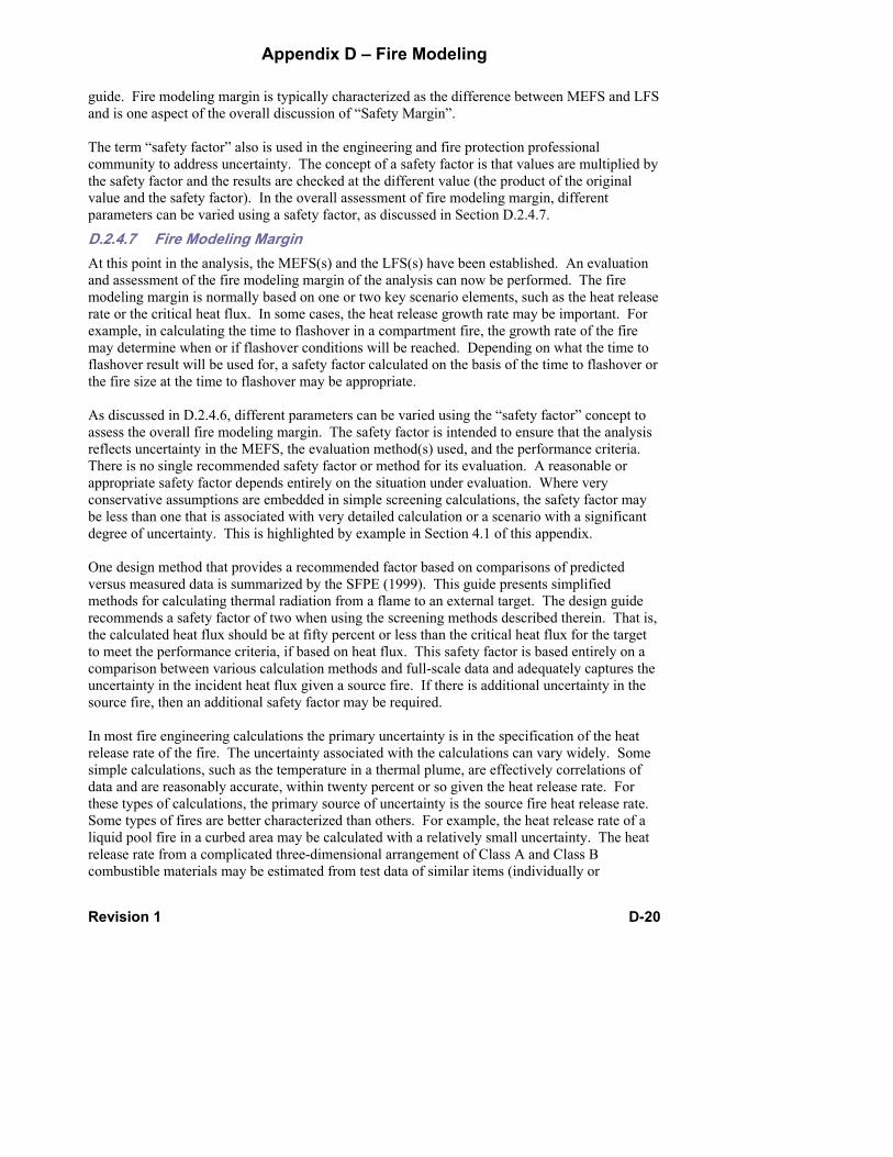
Appendix D – Fire Modeling
Revision 1 D-20
guide. Fire modeling margin is typically characterized as the difference between MEFS and LFS and is one aspect of the overall discussion of “Safety Margin”. The term “safety factor” also is used in the engineering and fire protection professional community to address uncertainty. The concept of a safety factor is that values are multiplied by the safety factor and the results are checked at the different value (the product of the original value and the safety factor). In the overall assessment of fire modeling margin, different parameters can be varied using a safety factor, as discussed in Section D.2.4.7.
D.2.4.7 Fire Modeling Margin At this point in the analysis, the MEFS(s) and the LFS(s) have been established. An evaluation and assessment of the fire modeling margin of the analysis can now be performed. The fire modeling margin is normally based on one or two key scenario elements, such as the heat release rate or the critical heat flux. In some cases, the heat release growth rate may be important. For example, in calculating the time to flashover in a compartment fire, the growth rate of the fire may determine when or if flashover conditions will be reached. Depending on what the time to flashover result will be used for, a safety factor calculated on the basis of the time to flashover or the fire size at the time to flashover may be appropriate. As discussed in D.2.4.6, different parameters can be varied using the “safety factor” concept to assess the overall fire modeling margin. The safety factor is intended to ensure that the analysis reflects uncertainty in the MEFS, the evaluation method(s) used, and the performance criteria. There is no single recommended safety factor or method for its evaluation. A reasonable or appropriate safety factor depends entirely on the situation under evaluation. Where very conservative assumptions are embedded in simple screening calculations, the safety factor may be less than one that is associated with very detailed calculation or a scenario with a significant degree of uncertainty. This is highlighted by example in Section 4.1 of this appendix. One design method that provides a recommended factor based on comparisons of predicted versus measured data is summarized by the SFPE (1999). This guide presents simplified methods for calculating thermal radiation from a flame to an external target. The design guide recommends a safety factor of two when using the screening methods described therein. That is, the calculated heat flux should be at fifty percent or less than the critical heat flux for the target to meet the performance criteria, if based on heat flux. This safety factor is based entirely on a comparison between various calculation methods and full-scale data and adequately captures the uncertainty in the incident heat flux given a source fire. If there is additional uncertainty in the source fire, then an additional safety factor may be required. In most fire engineering calculations the primary uncertainty is in the specification of the heat release rate of the fire. The uncertainty associated with the calculations can vary widely. Some simple calculations, such as the temperature in a thermal plume, are effectively correlations of data and are reasonably accurate, within twenty percent or so given the heat release rate. For these types of calculations, the primary source of uncertainty is the source fire heat release rate. Some types of fires are better characterized than others. For example, the heat release rate of a liquid pool fire in a curbed area may be calculated with a relatively small uncertainty. The heat release rate from a complicated three-dimensional arrangement of Class A and Class B combustible materials may be estimated from test data of similar items (individually or

Appendix D – Fire Modeling
Revision 1 D-21
collectively), but the estimate will also have pronounced uncertainty associated with it. If a reasonably well-defined fuel package is identified, a safety factor of two on the critical heat release rate versus expected heat release rate is often adequate but may even be unnecessarily high depending on the uncertainty in the fire size. The appropriateness of this safety factor depends entirely on the specific situation considered. The required safety factor may also depend on the failure condition or performance criteria established for the problem considered. For example, the use of a steady state critical heat flux value for establishing cable failure is inherently conservative because heat loss terms are ignored and it is assumed that the exposure duration is long relative to the transient response of the target. For short duration fire exposures (less than ten minutes), an acceptable safety factor will be less than that for a longer duration fire if failure criterion is based on steady state conditions. The analysis could be modified to take into account other important processes to yield a more realistic result. In this case, an even larger safety factor may be preferred because some inherent conservatism has been removed from the evaluation. The appropriate safety factor is a function of the problem being evaluated, the uncertainty in the calculation method used, the uncertainty in the definitions of the MEFS and the definition of the failure conditions or performance requirements. As a minimum, the safety factor should bound the uncertainty in the evaluation in terms of the source fire, critical value, and any other significant parameter. Thus an evaluation with little uncertainty requires a smaller safety factor than one in which there are several parameters with a significant uncertainty associated with each. In the event that the calculated safety factor is deemed inadequate, there are two options available. The first involves using a more accurate calculation procedure and more representative failure criteria (e.g., cable temperature versus critical steady state heat flux). This approach removes embedded conservatism from the analysis and generally requires more sophisticated calculation methods than those methods initially selected. For example, it may involve the use of a more realistic representation of the fire source as input for radiative heat transfer calculations in lieu of a simplified equivalent point source assumption. The second path involves evaluating the initial conditions and input parameters to ensure that they represent a maximum expected versus worst case limiting conditions. Alternatively, the MEFS may be revised to reflect more restrictive conditions of operation or hardware solutions, such as thermal radiation shields or additional insulation, or removal of a combustible fuel source. Since it is not unusual to initially perform screening or bounding calculations, subsequent refinement of both the calculation method /model selected and the input parameters used to determine the MEFS is a normal part of the evaluation process.
D.2.4.8 Documentation The assumptions, methods, input data, and the results should be documented in sufficient detail to permit a reviewer to reconstruct the analysis and check all relevant calculations and results. At a minimum the documentation should include the following elements: 1. Description of Problem

Appendix D – Fire Modeling
Revision 1 D-22
a. Objective of the analysis b. Regulatory basis c. Plant area or compartment d. Plant configuration assumptions e. Performance objectives
2. Calculation Method(s) a. Description of the calculation approach b. Reference to applicable equations used in analysis c. Model(s) name and version number d. Model validation/applicability references or information e. Assumptions and assumption bases
3. Maximum Expected Fire Scenario Description a. Scenario selection b. Scenario description c. Compartment/fire area physical description as related to scenario d. Ventilation configuration and size/flow rates e. Ambient environmental conditions
f. Source fire location, Rate of heat release as a function of time ( )(tQ& ), and related parameters
g. Failure criteria h. Data sources
4. Input Data a. Complete set of input data used for all calculations b. Copies of input files used for computer models
5. Results a. Complete set of all calculation results b. Copies of output files from computer models c. Relevant validation data if required
6. Limiting Fire Scenarios a. Set of input conditions resulting in failure/exceeding the performance criteria b. Range of variables evaluated c. Calculated safety margins d. Discussion of uncertainty in the analysis
7. Conclusion/Summary/Recommendations (if applicable) All documentation should meet the relevant quality assurance provisions. In some cases it will be advisable and/or necessary to include the model assumptions, data and results into the plant fire protection program.
D.3 Fire Source Terms for Maximum Expected Fire Scenarios This section describes methods for developing the MEFS(s) for selected fuel packages. Additional information and guidance is available in Appendix E of the EPRI Fire PRA Implementation Guide (EPRI, 1995; 2000), the EPRI Fire Modeling Guide (EPRI, 2002a), the SFPE Handbook (DiNenno, 2002), and many of the references listed in Section 6 of this Appendix. Guidance presented in this section is not intended to be a complete discussion of a specific topic, nor is it intended to preclude the use of any other methods.

Appendix D – Fire Modeling
Revision 1 D-23
D.3.1 Pool Fires MEFS that involve liquid pool fires can be developed using the following guidance:
Pool Fire Size 1. For confined spills, where curbs or equipment enclosures form the boundaries of a pool spill,
the enclosed area is the maximum spill area. 2. For unconfined spills, a steady state pool size can be calculated using data given by Gottuk et
al. (2002). Unconfined spills have fuel depths in the range of 1 – 3 mm and the burning rates are typically about one-fifth those for confined spills having the same area.
3. For unconfined spills where the fuel continues to flow, it is reasonable to derive an equivalent steady state pool size that results in a burning rate equal to the spill flow rate.
Specific data and calculation methods on liquid fuel fires can be found in Gottuk et al. (2002).
Spray Fires The effect of pressurized liquid spray fires cannot presently be modeled using readily available tools. The overall impact of spray fires in a compartment can be approximate by treating the spray as a heat release rate source term. This is a reasonable assumption if the spray is of sufficiently low momentum such that entrainment of air into the spray is not significant and the size of the liquid jet is not a large fraction of the compartment floor area. Limited data on spray fires is given in Appendix E of the EPRI Fire PRA Implementation Guide (EPRI, 1995; 2000). Note that in many actual spray fires, energy is contributed from both the spray fire and a pool fire that forms under the spray. CFD methods are available for calculating the details of a spray flame, but these are not available for general design or analysis. Limited data on radiation calculations from spray and jet flames is given by Beyler (2002). Target exposure calculations involving spray flame exposures require significant additional care.
D.3.2 Transient Combustibles In most plant areas, it is necessary to postulate a transient fuel fire source given the transient fuel loads. Transient fuel loads arise from normal operating conditions as well as maintenance or testing activities. Depending on the location in the plant and the general area use, transient combustibles will comprise at a minimum, of one or more trash or refuse bags. Large refuse bags may have heat release rates in the range of 150 – 350 kW, depending on the nature of the contents, packaging density, size and weight. Other transient loads, including lubricating oil, packaging material, and furniture items should be included as appropriate. Transient combustible materials should take into consideration transient loads allowed within the plant Fire Hazard Analysis and the combustible control program. Data on heat release rate characteristics of transient fuel loads is given in Babrauskas (2002), Babrauskas et al., 1992; and Grayson et al. (2000). The EPRI Fire PRA Implementation Guide also contains specific guidance for transient fuel loads in Appendix E (EPRI, 1995; 2000). Transient loads are included in the MEFS and LFS as appropriate by postulating transient loads in addition to normal fuel loads.
D.3.3 Cabinet Fires Heat release rates for electronics cabinets can be developed using data from large-scale cabinet fire tests using equipment similar ventilation and fuel loading. Two cabinet heat release rate

Appendix D – Fire Modeling
Revision 1 D-24
values measured by Chavez (1987) are in widespread use for fire PRA evaluations. In these evaluations, a lower heat release rate (65 kW) is used when the cables are IEEE-383 qualified and only one small cable bundle is expected to be involved. For other cases involving IEEE-383 qualified cables, 200 kW is assumed (EPRI, 1995; 2000). The heat release rate from electronics cabinets is a function of the cabinet ventilation, the combustible fuel load in the cabinet, and the fuel distribution within the cabinet. Fire testing conducted by Chavez (1987) and Mangs et al. (1994, 1996) attempted to evaluate the impact of these variables on the cabinet fire heat release rate. A summary of the test conditions is provided in Table 3-1. Transient heat release rate profiles for various cabinet fires are shown in Figure 3-1. Additional data is available in the EPRI Fire PRA Implementation Guide (EPRI, 1995; 2000). This guide gives energy release rate data for cabinet fires as a function of cabinet fuel loading, cable type and ventilation opening.
Table 3-1. Electronic Cabinet Fire Test Conditions
Ventilation Area (m2) Test No. Ref. Type Lower Upper
Fuel Load (MJ)
Peak HRR (kW)
Fire Duration
(min)
VTT-I 1 [1] Vent Grills, Door Ajar 0.050 0.11 925 385 at 40 min. 105
VTT-I 2 [1] Vent Grills 0.040 0.079 455 50 at 14 min 45
VTT-I 3-2 [1] Vent Grills 0.040 0.079 1,400 180 at 15 min 125
VTT-II 1 [2] Vent Grills 0.0097 0.054 1,500 175 at 36 min 105
VTT-II 2 [2] Vent Grills 0.0097 0.054 1,600 110 at 32 min 120
VTT-II 3 [2] Vent Grills 0.0097 0.054 1,500 100 at 13 min 120
ST #10 [3] Vent Grills 0.14 0.14 600 280 at 11 min 50
PCT #1 [3] Vent Grills 0.14 0.14 780 185 at 12 min 60
PCT #2 [3] Open door 1.30 1.30 1,000 950 at 11 min 40
1. Mangs et al. (1994) 2. Mangs et al. (1996) 3. Chavez (1987)

Appendix D – Fire Modeling
Revision 1 D-25
Time (min)
0 10 20 30 40 50 60 70 80
Hea
t Rel
ease
Rat
e (k
W)
0
200
400
600
800
1000
#1#2#3#4
Figure 3-1. Heat release rate of individual electronic cabinets in the cable spreading room. Curve #1 from ST#2 and PCT#1 (Chavez, 1987), Curve #2 from PCT#2 (Chavez, 1987), Curve #3 (Najafi et
al., 1999), and Curve #4 from Test 1 (Mangs et al., 1994).
Often, cabinets are located adjacent to or close to other cabinets. The potential for fire spread between adjacent cabinets can be estimated using experimental data from tests conducted by Chavez (1987) and Mangs et al., (1994, 1996). Chavez (1987) found that electronic cabinets that are not separated by an air gap may transmit sufficient heat to allow auto-ignition of cables in the adjacent cabinet. Wall temperature data obtained from by Mangs et al., (1994, 1996) indicates that fires will spread to adjacent cabinets approximately ten minutes after ignition of the initial burning cabinet. A heat release rate curve that combines the heat release rate contribution of individual cabinets with the expected ignition delay between cabinets is shown in Figure 3-2. In this example, fire spreads from a transformer to three adjacent electronics cabinets.
High Voltage Faults None of the electronic cabinet fire data currently available are relevant to the case of a high voltage arcing failure (NRC, 2002). No existing fire modeling calculation method can deal directly with these types of events. An approach to treating such scenarios would be to account for the initial electrical energy release as a zero oxygen consumption heat release rate and them assume ignition of all combustibles within a certain radius (1 – 2 m). Fire spread beyond this initial ignition zone could then be treated by existing methods as appropriate. Since the energy release rate for all models is given as input data, such an approach would enable the user to evaluate compartment-wide effects of such initiating events.

Appendix D – Fire Modeling
Revision 1 D-26
Transformer
#1 #2 #3
Fire Origin0 min 10 min 20 min
Top view showing fire spread to adjacent cabinets.
Time [min]
0 10 20 30 40 50 60 70 80
Tota
l Hea
t Rel
ease
Rat
e [k
W]
0
500
1000
1500
Transformer and #1 Ignite
#2 Ignites
#3 Ignites
#1 Burns Out
#2 Burns Out
Transformer and #3Burn Out
Figure 3-2. Heat Release Rate Profile and Depiction of Fire Spread from a Transformer to Adjacent Cabinets.
D.3.4 Cable Fires Cable fire growth rates may be approximated by empirical correlations relating bench scale heat release rate data to full scale fire spread and heat release rate data. The heat release rate and fire spread characteristics are strongly dependent on the following variables:
1. The cable jacket and insulation material.
2. The number and size of the cable conductors.

Appendix D – Fire Modeling
Revision 1 D-27
3. The cable construction.
4. The density and arrangement of cables in the tray, bundle, etc.
5. The cable orientation (vertical/horizontal).
6. The presence of fire retardant material on the cables.
The range of heat release rate data for a given type of insulation and jacket material varies widely. For example, heat release rate data for PE/PVC cable construction can vary between 200 kW/m² and 600 kW/m² for IEEE 383 qualified cables. Empirical data is available only for a small fraction of all cables current in use, so approximations are necessary when evaluating cable tray fire scenarios. A sample method that treats a cable tray fire a line fire that spreads in two directions is provided below. Other approaches may be used as appropriate. The heat release rate per unit length of the cable tray system is a function of the plan area of the cables as follows:
& & ,′ = ′′ ⋅q q Wtot fs p c (1)
where & ′′q fs is the full-scale single cable tray heat release rate (kW/m²) and Wp,c is the maximum plan width of the cables (m). The plan width is equal to the sum of all individual cable outer diameters or the actual cable tray width, which ever is smaller. If there are multiple trays, the total plan width includes the plan width on each cable tray within the array. The full-scale heat release rate per unit area is determined using the equation (Lee, 1985):
& . &′′ = ⋅ ′′q qfs bs0 45 (2)
where & ′′qbs is the heat release rate per unit area measured at an incident heat flux of 60 kW/m² in a bench-scale (cone calorimeter) apparatus.
Burning Duration The burning duration at a single point is in direct proportion to the quantity of combustible material available and the burning rate. The following equation is used to determine the burning duration:
tQqd
tot=
′′&
(3)
where td is the fire duration at a specific location (s), and ′Q is the energy load of the cable tray system (kJ/m).
Spread Rate Evidence suggests the spread rate in cable tray fires is a function of the bench-scale heat release rate (Lee, 1985). Lee (1985) correlated bench-scale data to moderate-scale tests in terms of an area spread rate for a single cable tray array. The cable tray array contained six tiers or two cable trays. Each individual tray within the array was 0.5 m wide (Sumitra, 1982).

Appendix D – Fire Modeling
Revision 1 D-28
As noted by Lee (1985), the correlated area spread rate is valid “…only to [for] cable tray arrangements, cable packing densities, and exposure fires similar to those tested by Sumitra.” The arrangement of the cable tray system is typically smaller than those that were tested. Consequently, some modification to the Lee (1985) methods is required before the test results can be applied to the configuration at hand. The correlation derived by Lee can be modified using the actual test observations by Sumitra (1982). Sumitra noted the number of trays involved before the onset of suppression for each test. This information, along with the burn area at the time suppression as determined by Lee (1985) was used to calculate the actual flame spread rate. Figure 3-3 shows the flame-spread rate versus bench-scale heat release rate along with a linear curve fit. The following correlation is obtained from the linear curve fit of the data:
v E qs bs= − ⋅ ′′ −( . ) & .7 55 3 125 (4)
where vs is the flame spread rate (mm/s) in one direction on horizontal cable tray.
Unit Heat Release Rate (kW/m2)
100 200 300 400 500 600 700
Flam
e S
prea
d R
ate
(mm
/s)
0
1
2
3
4
Flame Spread Rate Obtainedfrom Test Data
Linear Curve Fit of Test Data
Figure 3-3. Horizontal Flame Spread Rate as a Function of the Unit Heat Release Rate The flame spread velocity as calculated using Equation 4 may be compared to other test data on cable trays and cable fires for validity. Tewarson et al. (1993) observed that the horizontal flame spread velocity in communications cables is about 0.6 mm/s for a three-tiered cable tray arrangement. Investigations of a power cable fault fire (FTIC, 1989) concluded that the spread velocity in these cables was about 2 mm/s. Vertical cable trays with various types of cables have been shown to have a flame spread rate between 2 mm/s and 7 mm/s and presumably represent

Appendix D – Fire Modeling
Revision 1 D-29
an upper bound spread rate (Tewarson et al., 1988). Thus, the horizontal cable tray flame-spread rate is expected to lie between 0.6 – 7-mm/s, which is nearly the case for Equation 4 over the expected range of unit heat release rates for cables. Another consideration when estimating the cable tray flame spread rate is the packing density. Test data on vertical cable tray tests indicates that the flame-spread rate in cables is sensitive to the packing density (Hasegawa et al., 1983). Hasegawa et al. (1983) found that cable trays with a packing density of twenty-five percent had a fifty percent or greater reduction in the peak flame spread rate. Cable trays with a packing density approaching one-hundred percent also exhibited a flame spread rate reduction. Alternative (and lower) flame spread rates for cable arrays are given in the FIVE method documentation (EPRI, 1992), and discussed in the EPRI Fire Modeling Guide for Nuclear Power Plant Application (EPRI, 2002a).
Spread Distance The maximum flame spread distance from the point of origin in one direction is
X t vs d s= (5)
where Xs is the distance the flame spreads from the origin before the onset of burnout (m). Note that the total spread distance is twice this value because it is assumed that flame spread occurs in two directions. The method described above is applicable for single horizontal cable tray arrays. Vertical arrays spread flame much more quickly as noted above. No generic method exists for calculating or estimating this spread rate. For many problems vertical flame spread may be assumed to happen instantaneously. For complex horizontal cable array geometries (such as those which typically occur in cable spreading areas), a bench to full-scale spread correlation (viz., Equation 2) may be used to estimate the amount of cable involved if a slow or medium ‘t²’ growth rate fire is assumed. Note that none of those methods account for the change to flame spread rates that occur as the compartment heats up. As cables become immersed in hot gases and their surfaces preheated, the flame spread rate will increase. Methods for approximating the increase in flame spread rate can be derived from methods used to calculate flame spread on combustible surfaces (Quintiere, 2002). It is not presently possible to directly account for the effects of coatings on electrical cables without additional full or bench-scale data. Reference to full-scale cable tray test data may provide some guidance in establishing source fire characteristics of coated cables (Klamerus, 1978). At a minimum, coated cables passing IEEE-383 can be reasonably expected to equal the performance of IEEE-383 qualified cables from the standpoint of damageability.
D.4 Guidance on Application of Engineering Methods This section provides guidance and reference material on the use of engineering methods and models for specific applications.

Appendix D – Fire Modeling
Revision 1 D-30
D.4.1 Damage or Ignition of a Target This category of problems is widely encountered in NPPs due to its relationship with prescribed minimum separation distance requirements between certain systems and circuits. The general problem can be subdivided into two cases, one where the room size is large and the source fire relatively small such that compartment effects are negligible, and the other where compartment heating and/or oxygen depletion effects are expected to be significant.
D.4.1.1 Target Exposure: Negligible Compartment Effects Plumes and Ceiling Jet Exposure This case is illustrated schematically in Figure 4-1. Three sample target positions, T1, T2, and T3, are shown in Figure 4-1. Location T1 represents a target tat is immersed in the plume at some elevation above the flame. The axis-symmetric plume temperature may be calculated using methods found in Iqbal et al. (2002; 2004), FIVE, (EPRI, 1992; 2002a), Lattimer (2002) or Heskestead (2002). For line type flames and plumes or fires against walls or in corners, different correlations may be required (Iqbal et al., 2004). Location T2 represents a target within the ceiling jet zone. Correlations for estimating the temperature and velocity in a ceiling jet are available in Iqbal et al. (2002; 2004), Alpert (2002), Lattimer (2002), or FIVE (EPRI, 1992). These cases can also be evaluated using computer codes used for detector/sprinkler activation, for example, DETACT-QS/T2 (Portier et al., 1996; Evans et al., 1985; 1986) and LAVENT (Cooper, 1990).
Figure 4-1. Schematic of Target Exposure, No Compartment Effects

Appendix D – Fire Modeling
Revision 1 D-31
Where plumes or ceiling jets may flow through highly obstructed paths, as would be the case near the ceiling of a cable spreading room, the use of the methods described above could over-predict temperatures. Also, a target that is located outside of the flow path in an unobstructed configuration may become immersed in obstructed configuration. If such considerations are critical to the evaluation, then detailed calculations (such as a CFD analysis) should be pursued. The temperatures calculated for both plume and ceiling jet exposures are typically maximum values and occur along centerline of a thermal plume and near the ceiling for ceiling jets. If the target is not on the centerline, there are correlations for the temperature variation as a function of the distance from the maximum value that may be used. Heskestead (2002) gives the necessary correlations to perform this calculation for thermal plumes. In most applications (particularly for low ceiling heights), the use of maximum plume or ceiling jet temperature is most appropriate and recommended.
Flame Radiation In the situation noted by the target location T3 in Figure 4-1, the primary exposure is flame radiation (not in the presence of wind). This problem can be readily evaluated if the flame is approximated as a circular source with a simple target-flame geometry. Techniques are summarized in Beyler (2002), SFPE (1999), and Iqbal et al. (2002; 2004). Geometries that involve non-circular fire source (e.g. line fires), or irregular flame-target positions, intervening flame shields, etc., require a more complex calculation method. Beyler (2002) and Heskestad (2002) summarize several methods that address complex configurations. For complex geometries, the general process for calculating flame radiation effects is as follows.
1. Estimate the fire heat release rate.
2. Establish the dimensions of the flame base.
3. Calculate the flame height.
4. Estimate the emissive power at flame:
a. Use the radiative fraction of the total heat release rate divided by the flame surface area; or
b. Use the average flame temperature and emissivity; or c. Use an empirical correlation based on the fire diameter and other parameters.
5. Calculate view factor from flame to the target, accounting for flame shields and other obstructions.
6. Apply any corrections for the transmissivity through boundaries and absorption by intervening gas (can be neglected for most cases).
7. Calculate the radiant flux at target.
This procedure described above may be used for most flame and flame/target geometries. Summarized below is the application of four different flame radiation calculation methods of variable complexity. The examples illustrate the relationship between methods used and the appropriate safety margin.

Appendix D – Fire Modeling
Revision 1 D-32
Comparison of Flame Radiation Calculation Methods An example of applying various calculation procedures and the effect it has on the appropriate safety margin is given in this section. Four methods for calculating flame radiation are described and compared with experimental data. The basis for comparison between the methods is calculated heat flux for the data set used to validate the point source model. The models are provided under the assumption that there is no wind. Wind effects are addressed at the end of this section. Classical Point Source Method The classical point source model was used in this analysis because it is simple to apply and it is the only method that does not require a determination of the diameter of the fire. The point source model assumes that the radiant energy is released at a point located at the center of the fire. The heat flux is inversely related to the separation from a source fire the following equation (Drysdale, 1999):
24 RQ
q pr
πχ &
& =′′ (6)
where q ′′& is the heat flux (kW/m²) at a distance R (m) from the center of the flame, Πr is the is the energy fraction released as thermal radiation, pQ& is the peak heat release rate (kW). As can be seen in Equation 6, only the peak heat release rate and the separation distance are required to calculate the heat flux to a target. In most instances, the fraction of energy released as radiation varies between 0.03 and 0.45 (SFPE, 1999; Tewarson, 2002) with most data falling between 0.1 and 0.3. A value of 0.35 is initially assumed in the following example analysis and based on comparison with the available test data an appropriate safety margin is determined. Note that assuming a different value would result in a different safety margin but not a different conclusion. It is also assumed that the separation distance R is equal to the horizontal distance between the edge of the source fire and the edge of the target. Because the horizontal separation distance will always be less than the distance to the center of the flame, the heat flux values predicted by Equation 6 will be more conservative using the horizontal separation distance. Equation 6 has been compared to actual test data from pool fires with diameters of less than 3 m because it is expected that the assumptions described above would not apply to large diameter source fires. Table 4-1 summarizes the experimental data sets that were used in this comparison. Figure 4-2 shows a plot of the measured versus predicted heat flux values Equation 6 using an assumed radiative fraction of 0.35 as described above and a separation equal to the horizontal distance from the edge of the source fire. Although most of the target heat fluxes are conservatively over-predicted, there are still enough data points that are under-predicted to warrant the use of a safety margin.

Appendix D – Fire Modeling
Revision 1 D-33
Table 4-1. Summary of Experimental Data Compared with Point Source Model
Predictions Data Reference Type of Fuel Fire Diameter (m) Number of Data
Points Seeger (1974) Fuel Oil 1.6 4
Yumoto (1977) Gasoline 1.0 to 1.5 11
Dayan et al. (1974) JP-4 1.2 4
Dayan et al. (1974) JP-5 2.4 to 3.1 8
Hagglund et al. (1976) JP-4 1.1 to 2.3 11
Koseki et al. (1991) Crude Oil 1.0 to 3.1 5
Koseki et al. (1988) Heptane 1.0 to 2.0 2
Koseki et al. (1989) Heptane 3.1 1
Mea
sure
d H
eat F
lux
(kW
/m2 )
0 .1 1 1 0 1 0 0
P re d ic te d H ea t F lux (k W /m 2 )
0 .1
1
1 0
1 0 0
JP -4 , JP -5 , G a so lin e , & F u e l O il P o o l F ireH e p ta ne D ik e F ireC ru d e O il P o o l F ireH e p ta ne P o o l F ire
U n d e r-P re d ic te d D a ta
O ve r-P re d ic te dD a ta
Figure 4-2. Predicted Versus Measured Target Heat Fluxes Using the Classical Point Source Model Figure 4-3 shows point source model predictions using a safety margin of 1.5, an assumed radiative fraction of 0.35 as described above, and a separation distance equal to the horizontal distance from the edge of the source fire. As can be seen, all of the data is either accurately predicted or conservatively over-predicted. In some instances the heat flux is over-predicted by a considerable amount. Nevertheless, Figure 4-3 shows that with some relatively moderate

Appendix D – Fire Modeling
Revision 1 D-34
assumptions to the initial model, the calculation can be shown conservative for a wide range of fuels and fire sizes without the need for evaluating fire specific parameters such as the diameter and flame height.
Figure 4-3. Predicted Versus Measured Target Heat Fluxes Using the Classical Point Source Model with a Safety margin of 1.5
Shokri and Beyler Correlation The Shokri and Beyler correlation requires the determination of the fire diameter. The following equation is used in this method to calculate the heat flux to a target (Shokri et al., 1989):
57.1
4.15−
⎟⎠⎞
⎜⎝⎛=′′
DRq& (7)
where D is the source fire diameter (m). The radial separation R is the distance between the center of the source fire and the edge of the target. Figure 4-4 shows the predicted heat flux versus the measured heat flux at a target for the same data set used to validate the point source model. Figure 4-4 shows that the Shokri and Beyler correlation under estimates about half of the data points and over estimates the other half. This is the basis for a recommended factor of safety of two in the SFPE Engineering Guide (SFPE, 1999). Detailed Method of Shokri and Beyler Shokri et al. (1989) present a more detailed method than the Shokri and Beyler correlation summarized above and the results are improved. The heat flux to a target is calculated using the following equation:
EFq =′′& (8)
Mea
sure
d H
eat F
lux
(kW
/m2 )
0 . 1 1 1 0 1 0 0
P r e d ic t e d H e a t F lu x ( k W /m 2 )
0 .1
1
1 0
1 0 0J P - 4 , J P - 5 , G a s o lin e , a n d F u e l O il P o o l F ir eH e p t a n e D ik e F ir eC r u d e O il P o o l F ir eH e p t a n e P o o l F ir e
U n d e r - P r e d ic t e dD a t a
O v e r - P r e d ic t e dD a ta

Appendix D – Fire Modeling
Revision 1 D-35
Figure 4-4. Predicted Versus Measured Target Heat Fluxes Using the Shokri and Beyler Correlation
where E is the emissive power of the fire flame (kW/m²) and F is the radiation view factor between the target and the flame. The emissive power of the flame is determined using the following equation (Shokri et al., 1989):
DE 00823.01058 −⋅= (9)
where E is in kW/m² and D is in meters. The configuration factor between the target and the flame is a function of the flame height, the fire diameter, the shape of the flame, and the orientation of the target. Shokri and Beyler assume that the flame can be approximated as a cylinder with a diameter equal to the diameter of the source fire and a height equal to that of the flame. The equations for this radiation configuration factor geometry are summarized in Shokri et al., (1989). Figure 4-5 shows the predicted versus measured target heat fluxes for the same data set used to validate the point source model. The figure indicates that this method is much better than the Shokri and Beyler correlation, though some data is still under estimated, hence a lower factor of safety may be warranted.
Mea
sure
d H
eat F
lux
(kW
/m2 )
0.1 1 10 1000.1
1
10
100JP-4, JP-5, Gasosene, & Fuel Oil Pool FireHeptane Dike FireCrude Oil Pool FireHeptane Pool Fire
Predicted Heat Flux (kW/m2)
Over-PredictedData
Under-PredictedData

Appendix D – Fire Modeling
Revision 1 D-36
Figure 4-5. Predicted versus Measured Target Heat Fluxes Using the Shokri and Beyler Procedure
Method of Mudan and Croce The method of Mudan and Croce is similar to the detailed Shokri and Beyler method, however different correlations for the flame height, flame emissive power, and the shape factor are employed. This method is summarized in Beyler (2002) and by SFPE (1999).
Sample Application Comparing the Four Heat Flux Models This section presents an application that compares the calculated predictions of each heat flux model. The sample fuel package is a 1.5 m diameter combustible material fire. The assumed heat release rate per unit area is 400 kW/m². The incident target heat flux at several distances was calculated using each of the four methods discussed above. Table 4-2 summarizes the predictions of each method. The point source model and the Shokri and Beyler correlations, both of which are screening methods, yield the most conservative results near the source fire and is the next most conservative method at distances away from the fire. It should be noted that all correlations are conservatively applied in this case in so far as the fuel package is treated as a pool fire. The results in Table 4-2 suggest that the safety margin is generally greater for the screening methods near the source fire, where the greatest error would be expected, and approaches the more detailed methods at distances away from the source fire.
Mea
sure
d H
eat F
lux
(kW
/m2 )
0.1 1 10 100
Predicted Heat Flux (kW/m2)
0.1
1
10
100JP-4, JP-5, Gasosene, & Fuel Oil Pool FireHeptane Dike FireCrude Oil Pool FireHeptane Pool Fire
Under-PredictedData
Over-PredictedData

Appendix D – Fire Modeling
Revision 1 D-37
Table 4-2. Comparison of Heat Flux Predictions for Miscellaneous Fire Example
Heat Flux (kW/m²) at Method 0.5 m 1.0 m 1.5 m 2.0 m 2.5 m Point Source Model1 117 29 13 7.3 4.7
Shokri/Beyler Correlation 86 29 15 10 7
Detailed Shokri/Beyler 31 17 10 6.9 4.9
Mudan/Croce Method 67 39 25 17 12 1Point source model with a safety margin of 1.5 and a radiant fraction of 0.35.
Wind Effects If wind effects cannot be ignored, then some modifications to the radiation heat flux calculation approach are necessary. This applies only to the detailed methods (the Shokri and Beyler method and the Mudan and Croce method). The point source method and the Shokri and Beyler method should not be used if wind effects are expected to be significant. Wind effects on the radiant heat flux from a source fire to a target are characterized by the following elements:
1. Increased flame length
2. Deflection of the flame.
3. Increased convective heat loss at the surface of the target.
The first two wind impacts cited above typically have an adverse impact on the target response insofar as they tend to lead to an increased heat flux and thus more rapid heating of a target. At sufficiently large distances, the flame deflection may actually become a favorable attribute because the distance the flame may moves toward the target is counterbalanced by the reduction in the view factor due to the decreased vertical flame height associated with large deflection angles. The last element is always a positive attribute because the target loses a thermal energy to the surroundings more efficiently in the presence of a moving air stream. Significant wind may increase flame length in the direction parallel to the wind flow. Thomas [1962] provides correlations of flame lengths when there is significant wind. For deflection angles less than 45°, the increase in flame length can vary between 12 – 30 percent [SFPE, 1999]. Flames will deflect parallel to the wind and may move toward or away from the target. Typically, it is most conservative to assume that the flames deflect toward the target, thus decreasing the distance between the radiating surfaces and the target. The deflection angle is a function of the non-dimensional wind velocity, given by the following equation [Beyler, 2002]:
3/1*
⎟⎟⎠
⎞⎜⎜⎝
⎛ ′′=
v
x
Dmg
uu
ρ&
(9)

Appendix D – Fire Modeling
Revision 1 D-38
Where u* is the non-dimensional wind velocity, uw is the wind velocity (m/s), g is the acceleration of gravity (m/s²), m ′′& is the mass loss rate of the fuel supplying the fire (kg/s-m²), D is the diameter of the fire (m), and vρ is the density of the thermal plume/fire (kg/m³). The deflection angle is given by the following [Beyler, 2002]:
11)cos(
11)cos(
*
*
*
≥=
<=
uu
u
θ
θ
where θ is the deflection angle (radians). Shape factor equations for tilted fires differ from fires that are assumed vertically [SFPE, 1999]. Refer to SFPE [1999] or Beyler [2003] for details regarding the shape factor equations for tilted fires. Figure 4-6 depicts the shape factor as a function of separation distance and tilt angle for a fire with a height-to-radius ratio of 6. The results are similar for fires with other height-to-radius ratios.
Figure 4-6. Radiation Shape Factor as a Function of Separation Distance and Tilt Angle for Fires
with a Height-to-Radius Ratio of 6 When determining the response of the target, the additional cooling resulting from the moving air stream should be accounted for. The cooling capacity is a function of the velocity of the air stream. A low air velocities, natural convection is the dominant mode of convective heat loss; at high air stream velocities, forced convection is the dominant mode; at moderate air stream velocities a mixed forced-natural condition arises [Incropera et al., 1985; Gebhart et al., 1988]. The classification of an air stream as low, moderate, and high velocity is a function of the air temperature, the target orientation and shape, and the target temperature. Incropera et al. [1985],

Appendix D – Fire Modeling
Revision 1 D-39
Atreya [2002], and Gebhart et al. [1988] provide correlations for the three flow regimes and various target shapes and orientations.
D.4.1.2 Target Exposure: Significant Compartment Effects Compartment effects are critically important to fire engineering calculations. These effects manifest themselves in several ways. It is important to ensure that any analysis captures these effects where important. They include: 1. The formation of a hot gas layer that thermally exposes all elements located within that layer.
At relatively low temperatures, this exposure is primarily convective, and as this temperature approaches 500°C, thermal radiation heat transfer begins to dominate. In many cases both heat transfer mechanisms should be accounted for.
2. The hot gas layer causes an increase in plume and ceiling jet temperatures since the plume and jet are entraining heated air. Any calculations involving direct exposure from a plume or ceiling jet that entrains heated air must account for this effect.
3. The hot gas layer has a reduced oxygen concentration. This has two primary effects. The first is that when the flame zone is immersed in the hot gas layer, the flame entrains gases and air at reduced oxygen concentrations. This results in lengthening of the flame and a decrease in heat release rate/unit length of the flame (energy release rate). This same effect will cause an increase in soot production and in the yield of carbon monoxide (CO).
4. At elevated hot gas layer temperatures, radiation from the hot gas layer will cause an increase in the burning rate of objects located within the layer and eventually radiation from the hot gas layer will increase the burning rate of objects located below it. In the limiting case (flashover), objects below the hot layer will ignite and the compartment fire will transition to a post-flashover, and often ventilation limited, state.
In any given analysis, some or all of the above effects may not be significant or they may be readily accounted for. A small fire in a large space is an ideal example of such a case. Nevertheless, compartment effects should always be considered, and if they are found to be insignificant, appropriate documentation should be provided. A typical case where compartment effects are or may be important is depicted in Figure 4-7. There are two basic approaches to these types of problems. The first involves using engineering calculations to calculate plume and ceiling jet exposures (T1, T2) as if there were no hot layer. Then estimate the hot gas layer temperature using either engineering calculations such as Iqbal et al. (2002), Walton et al., (2002), zone models such as CFAST (Peacock et al., 2005) or MAGIC (Gautier, 2002; EPRI, 2002b), or field models such as FDS (McGrattan et al., 2002) or JASMINE (Cox et al., 1986). The average hot gas layer temperature rise due to compartment heating is then added to the temperature increase due to the plume or ceiling jet. Although this will result in slightly over-predicted exposure temperatures if the thermal plume is not fully immersed in the hot gas layer (as assumed), the approach has the advantage of exploiting a range of conditions for plumes and ceiling jets and allows easy calculations of a range of target positions. For targets located outside of the plume or ceiling jet, the exposure temperature can be calculated directly from the hot gas layer temperature. An alternative approach is to use a zone model to

Appendix D – Fire Modeling
Revision 1 D-40
calculate the heating of a target in the hot gas layer and exposed to flame and hot gas layer radiation. A third approach is to use a CFD model, such as FDS or JASMINE, to calculate the temperature and velocity field at a target location. CFD codes can be used to great advantage where resolution in a complex flow field or geometry is required. One disadvantage that CFD models in general and LES CFD models in particular have is in calculating radiant heat fluxes from flames to targets. Much of the thermal radiation characteristics of the flame occur at sub-grid scales in an LES simulation and thus cannot be resolved. Furthermore, radiation calculations are tune consuming for CFD codes in general. To compensate for this, CFD models incorporate various approximate thermal radiation sub-models as necessary. These models often have not been verified and the results may be highly sensitive to the actual grid scale used. In this case of FDS, there is little published data on the validation of its flame radiation sub-model.
Figure 4-7. Schematic of Target Exposure Problem with Compartment Effects
D.4.1.3 Target Response Calculations Damage to or ignition of target items is generally handled in two ways. In the simplest case a threshold gas temperature or critical heat flux value is used that is based on some empirical data. For example, IEEE 383 qualified cables are often assumed to fail when the heat flux exceeds 10 kW/m² (EPRI, 1992). Similar gas temperature criteria are also available. The second approach involves calculating the heat transfer to the target and subsequent transient heating of the target until some failure criteria is met.

Appendix D – Fire Modeling
Revision 1 D-41
The use of steady state heat flux or gas temperature failure criteria is conservative and simple. Depending on the problem under evaluation, such methods may result in excessively conservative values. The calculation of the transient heating of the target will normally result in longer predicted failure times and in many cases may be used to show that failure does not occur despite an exposure temperature that exceeds a threshold temperature value. These transient calculations are, however, subject to increasing uncertainty. For cases where a threshold gas temperature or critical flux are used and the calculated factor of safety is not considered adequate, additional calculations involving transient heating of the target will provide a quantitative improvement in the factor of safety. Target heating calculations can be performed using several methods. The first broad category involves exact solutions of thermally thin and semi-infinite solid surface heating problems. These are standard engineering calculations that can be applied in special cases. These calculations are embedded as target heating models in some zone models, notably MAGIC and to a lesser extent, CFAST. The second type of heating calculation involves the use of finite difference or finite element heat transfer computer codes. There are many such codes available for this application. HEATING (Childs, 1998), as an example, has been used for target heating calculations.
D.4.2 Fire Spread on Contiguous Combustibles This class of problems relates to fire between fuel packages that are continuous or close enough that direct flame spread mechanisms are important. No validated model exists to calculate flame spread directly, with the possible exception of combustible wall and ceiling surfaces. Therefore, any problem involving direct flame spread must be estimated using some combination of empirical data and calculations. Flame spread on cable fires is an example of this class of problem. Methods for estimating fire growth and flame spread rate for cables are given in Section 3.4 of this Appendix. Typically, ignition of other fuel packages may be estimated using ignition criteria (immersion temperature, surface temperature, and/or incident heat flux), and one or more of the calculation methods described in Section. If the ignition criteria are met, then it is reasonable to assume the object would ignite. If room temperatures exceed critical flashover temperatures (500°C – 600°C), then it is reasonable to assume combustible materials below the smoke layer, or in the smoke layer if there is sufficient oxygen, would ignite. A related issue often arises when modeling electronic cabinet fires. For cases where more fire-stopped exposed cables penetrate the top of the cabinet a direct contiguous flame spread path to cable trays located above the cabinet exists and must be calculated. Any modeling or calculations done to evaluate the impact of cabinet fires should include as part of the source fire term flame spread to the cables above.
D.4.3 Thermal Detector Activation Time This problem, in effect, is a calculation of the thermal response of a lumped heat capacity thermal element to a temperature and velocity field within a thermal plume or a ceiling jet. It is analogous to the target damage problem, except in this case the target has very high conductivity and low mass (e.g., a sprinkler fusible link).

Appendix D – Fire Modeling
Revision 1 D-42
The calculation of sprinkler or heat detector response time requires two steps. 1. Calculate the temperature and velocity at the detector position in the plume or ceiling jet. 2. Solve the transient heating equation for the thermal link or detector using the Response Time
Index (RTI) of the thermal element. Evaluation of the plume and ceiling jet temperatures and velocities as a function of position are done using correlations. The transient heating of the thermal element is performed using a lumped heat capacity model. The RTI is a sprinkler specific constant that is generally determined by the manufacturers. The lower the RTI value, the quicker the sprinkler will respond to a temperature increase. Generally, standard response sprinklers have RTI values that are between 80 – 110 m0.5-s0.5 (Budnick, 1984; Puchovsky, 1996). Quick response sprinklers can have RTI values between 40 and 60 ft0.5-s0.5 (Budnick, 1984; Puchovsky, 1996). The actuation temperature for ordinary sprinklers is normally between 68°C (155°F) and 74°C (165°F). Sprinkler models are available with ratings as low as 57°C (135°F) and greater than 149°C (300°F). Only ordinary sprinklers are considered in this analysis. Closed form approximations for fires with a heat release rate growth that is proportional to time squared are given by Schifiliti et al. (2002). Sprinkler and thermal detector actuation models are for flat open ceiling configurations, a notable example of which is DETACT-QS (Evans et al., 1985; 1986; Portier et al., 1996). DETACT-QS calculations have been compared to experimental data in several studies. These studies include Madrzykowski (1993) and Walton et al. (1993). In general, the DETACT-QS model performs well considering the inherent uncertainty in the some of the input parameters, such as the sprinkler RTI value and the actual source fire heat release rate. In some instances, the effects of a hot layer were found to be significant and should be included in the evaluation (Madrzykowski, 1993). The activation of smoke detectors can be treated in an analogous way. There are two basis methods: the Temperature Rise Method and the Optical Density Method (Schifiliti et al., 2002; NFPA 72, 1999). The Temperature Rise Method assumes that the optical density to temperature rise ratio remains constant for a given fuel and combustion mode (Heskestad et al., 1977). The latter part of this definition is often ignored and a temperature rise of 10°C – 15°C is used as the alarm thresholds for all detectors and fires (Schifiliti et al., 2002). The assumed relationship has little or not basis (Beyler et al., 1991; Schifiliti at al., 1996) and there is data suggesting that detectors may alarm at temperature rises as low as 1°C (Mowrer et al, 1998; Gottuk et al., 1999; Wakelin, 1997). The Optical Density Method involves calculating the smoke concentration at the detector and comparing the smoke level to an alarm threshold for the detector. Using the mass loss of the fuel, the volume into which the smoke accumulates, and an empirically derived fuel constant, an optical density may be computed. Typically, a zone model or a CFD model is used for this type of calculation. Alarm thresholds vary much as RTI values vary with a sprinkler. Data is available for average and bounding values (Gottuk et al., 1999; Ross-Phersson et al., 2000;

Appendix D – Fire Modeling
Revision 1 D-43
Wong et al., 2000). Uncertainty in this calculation arises from the source fire mass loss and smoke yield and the sensitivity of the detection device.
D.4.4 Habitability Calculations These calculations refer to calculating the conditions under which personnel would be threatened. They arise from these primary effects, reduction in visibility due to smoke, effects of temperature or heat flux and the effects of toxic gases. Visibility is a function of the optical density of the smoke in a hot layer, which in turn is a function of the mass of material burned, the soot properties of the material, and the volume of material occupying the area of concern. It is either directly calculated in the model or can be readily calculated from the results of either zone or modeling. It requires the specification of accurate soot yield and soot optical properties as input data. Methods for calculating visibility are given by Mulholland (2002) and Jin (2002). Temperature effects are based on time/temperature relationships for human exposure. Data on limiting thermal radiation and temperature conditions for human exposure can be found in Beyler (2002) and Purser (2002). These data indicate tolerance levels of 110°F for between 10-25 minutes in dry air. Toxicity assessments are normally not required in NPP applications. Calculation methods are available to estimate time to incapacitation for combination of fire products including CO, CO2, HCl, acrolein and formaldehyde, using a Fractional Effective Dose, or FED approach. These methods can be readily applied using the results of zone and CFD models. Purser (2002) provides a methodology for estimating time to incapacitation.
D.4.5 Suppression Effects The effects of fire suppression systems on fire growth rate, room temperature conditions, etc. can only be crudely accounted for using existing zone and CFD models. CFAST uses completely empirical measured room temperature and heat release rate reductions values based on a limited set of sprinkler tests (Peacock et al., 2005). This method cannot be used in general. CFD codes have been used in special applications to calculate the effects of sprinkler and water spray systems. The use of models for routine design or analysis purposes is currently not possible. To account for suppression effects one is forced to rely on full-scale test data from tests that approximate the conditions being evaluated. A very crude but conservative approximation would be to hold the heat release rate constant at the time of sprinkler operation. Alternatively, one could specify a cooling rate based on relevant full-scale test data.
D.4.6 Flashover Calculations The potential for flashover to occur is of interest when assessing whether of not room contents are damaged or lost and fire spread across rated and unrated boundaries is possible. These types of calculations may be used in combination with other assessments, such as estimating if automatic suppression occurs prior to flashover or when preparing a time line for a fire scenario. These calculations are used to quickly determine the minimum heat release rate necessary to cause flashover. Flashover typically occurs when the hot layer temperature exceeds 500-600°C,

Appendix D – Fire Modeling
Revision 1 D-44
and effectively marks the location in a fire development history where the fire becomes ventilation limited. Flashover is characterized by rapid ignition of available fuel surfaces, primarily due to exposure to thermal radiation (Walton et al., 2002). There are several methods available for estimating the potential for flashover. There are several screening methods that perform an energy balance between the compartment volume, the energy loss through the boundaries and openings, and the source fire heat release rate (Walton et al., 2002). These methods generally do not consider ventilation aspects other than as a source of energy loss. These methods may be used to determine a minimum fire size necessary to reach a flashover condition. More detailed screening methods provide a fire size and time to flashover at the particular fire size (Walton et al., 2002). A determination as to whether or not the minimum flashover fire size is possible based on the existing combustible fuel packages is then made. Section 6.1 of this appendix provides references for evaluating fire sizes. If the minimum flashover fire size is possible, an assessment of the duration in combination with the minimum fire size is then necessary, namely is there a sufficient quantity of fuel available to sustain the fire long enough to cause flashover. Flashover screening calculations may be computed from correlations (Walton et al., 2002) or from software such as FASTLite (Portier et al., 1996) and Iqbal (2002; 2004). Note that these types of software calculations are not currently validated for applications in nuclear power plants, however used within the proper limitations and with adequate documentation and validation they should be satisfactory. The potential for flashover may also be evaluated using zone and CFD computer models. Zone models essentially perform the same type of energy balance as the screening calculations but typically include more detailed source fire, boundary heat loss, and volume terms. One significant improvement that zone and CFD models have over the screening correlations is that they will determine whether or not a particular fire size is possible given the ventilation conditions. Thus, if a flashover correlation identifies a minimum fire size necessary to cause flashover, and it is concluded that a fuel package is present that would have such a heat release rate, a zone or CFD model may be used to ascertain whether or not this heat release rate can be sustained given the ventilation.
D.4.7 Post-Flashover Temperature Calculations These calculations are a special case of compartment fire temperature calculations. They normally used in cases where flashover is assumed/predicted and the primary variable of interest is the room temperature. This temperature is usually used to evaluate the fire resistance of structural elements or a fire barrier. Most post-flashover calculations assume that the energy release rate of these fires is limited by the air inflow available (ventilation limited burning). While zone and CFD models can be used for calculating post-flashover temperatures, time/temperature relationships have already been calculated and are available in table and graphical form (Milke, 2002). In addition, zone models often significantly over-predict layer temperatures in post flashover conditions. In addition to those data, post-flashover temperature calculations may also be estimated using methods given by Walton et al., (2002) and Iqbal et al. (2002; 2004). An example of a post-flashover fire model is COMPF2 (Babrauskas, 1985), which was developed for evaluating the compartment temperature under these circumstances.

Appendix D – Fire Modeling
Revision 1 D-45
D.4.8 Compartment to Compartment Fire Spread The potential for compartment to compartment fire spread may be used estimate impacts of a fire in areas beyond the initial fire area. Compartment to compartment fire spread may occur through a number of means:
Fire spread across unrated construction.
Compromising a fire barrier.
Compromising a penetration seal.
Thermal radiation.
Smoke products.
Fire spread across boundaries may be the result of a flashover condition in the room of origin or the development of a hot spot on the unexposed side due to a localized fire exposure. There are several approaches available for estimating the likelihood and time lag for inter-compartment fire spread. Fire spread across unrated construction generally should be assumed if the room of origin reaches flashover conditions. In some cases, a time lag may be assigned based on test data. An example of this would be 5/8 inch gypsum on steel stud construction, which typically provides about 20 minutes fire resistance per layer. An alternate approach, if the construction is well sealed, would be to evaluate the transient temperature profile through the material/assembly using a conduction model. The exposure could be determined from a fire model (zone, CFD) or from estimates based on the fuel load and ventilation conditions. If a localized exposure is expected, correlations based on the fire size may be used in lieu of compartment temperature data. Fire spread is assumed when the unexposed side of the boundary exceeds an ignition threshold, typically 325°F for Class A combustible material [ASTM E119, 1999]. Fire spread across fire barriers and rated penetration seals is normally assumed if a post-flashover fire exposure exceeds the rating of the fire barriers or seals. Thus, if a 4 hour fire post-flashover fire is postulated in a space, then fire spread across a 3 hour fire barrier is likely. Unfortunately, the exposure fire rarely corresponds to the ASTM E119 Standard Time-Temperature Curve, such that fire spread across the boundary does not necessarily correspond to the listed rating. In many cases, the ASTM E119 temperature profile is more severe, but this is not always so. The most practical means of predicting the time fire spreads across a boundary in the absence of a specific test is to perform a thermal analysis given the exposure temperature/heat flux. Once the unexposed temperature of the boundary or the seal exceeds the critical ignition temperature, typically 325°F (but greater in some cases if the combustibles are cables in a penetration seal), the fire spread should be assumed. Consideration should be given for a localized exposure in combination with a room wide post-flashover exposure. Other means by which compartment to compartment fire spread could occur is thermal radiation from a source fire or hot combustion products entering an area and igniting combustible materials. These types of fire spread would occur only under specialized circumstances. For example, large external fire separated from a building by a fixed distance may radiate sufficient energy so as to spread into the structure either through window or door openings or unrated

Appendix D – Fire Modeling
Revision 1 D-46
construction. Fire spread by a hot smoke layer could occur if a space that is open to a corridor or other type of intervening space normally free of combustibles reaches flashover conditions. The smoke products spread into the corridor and other areas adjacent to this corridor. If the smoke is sufficiently hot, it may ignite combustible materials either directly or via thermal radiation. These types of scenarios generally require radiation calculations and/or computer fire models to adequately assess.
D.5 Validation of Engineering Methods The limits of the various types of models have been described in a broad sense throughout this Appendix, particularly in the context of the applications discussed in Section 4. This section identifies additional limits and considerations as well as model validation. There are no fire-related engineering methods or models that have been validated over the entire range of applications for which they might reasonably be used by the NRC or within the fire protection community in general. There have been and are substantial and ongoing efforts directed at performing validation studies on various calculation methods and models (Beall, 1997; Dey, 2002). ASTM E-1355 (1997) gives general guidance on evaluating the predictive capability of fire models. NRC is currently in the process of verifying and validating several fire models and plans to develop a pool of acceptable fire models and acceptable applications of these fire models using the ASTM E-1355 (1997) Standard (Dey, 2002). In the absence of such a pool, adequate documentation will be necessary that demonstrates the appropriateness of the model, the application of the model, and the overall approach to evaluating the problem.
Engineering Calculations Most calculation procedures are based on correlations of experimental data. These include relationships for determining the flame radiation, plume and ceiling jet temperature and velocity, flashover calculations, and so on (DiNenno, 2002; Drysdale, 1999). These correlations are based on full-scale test data and are expected to give reasonable results within the limits of the mathematical model on which they are based. When using correlations, it should be verified that application is within the proper limitations. It is reasonable to use these correlations for most NPP applications and they are primarily limited by uncertainty beyond the range of the data set on which they are correlated. In NPP applications, this is often occurs when dealing with spaces that have a very large ceiling heights (over 30 to 40 ft), highly obstructed flow paths, or very large fires in large spaces (e.g. turbine halls).
Zone Models Zone type fire models have been extensively compared to experimental data for a range of applications, including those associated with NPPs (Floyd, 2002; Dey, 2002; Peacock et al., 2005; Peacock et al., 1993; Nelson et al., 1991; and Dembsey et al., 1995). An ongoing project supported by the NRC has conducted an international set of validation studies for a range of zone and CFD codes for typical NPP applications (Dey, 2002). These validation data sets include room sizes up to 1,300 m3, fire sizes between 100 kW to 2.5 MW, and a range of fire sources. Thus far, the project has found that many of the models evaluated, including CFAST and MAGIC, give reasonable results for the applications considered.
Appendix D – Fire Modeling
Revision 1 D-47
CFD Models CFD models have been subjected to many validation studies, primarily for non-nuclear applications (Cox et al., 2002; Floyd, 2002; Cox et al., 1986; McGrattan et al., 1998a, Miles et al., 1999). As noted above, there is currently an effort to study the predictions of both zone and CFD models in NPP related applications being performed under an NRC-supported international model evaluation project (Dey, 2002). Preliminary results indicate that CFD models such as FDS, JASMINE, and VULCAN provide reasonable temperature profiles for some types of fire and spaces that are typical of NPPs. Much of the variation in the model results was noted to be a direct result of the manner in which the user applied the model to the scenario (Dey, 2002). The major advantage of CFD codes relative to validation is that they, as a group, are inherently less dependent on empirical data or approximations. The codes utilizing large eddy simulation (LES) methods to predict the turbulent flow behavior of fire-induced flows do so without the need for direct manipulation of the turbulence characteristics and are thus readily adapted for simulating smoke conditions. CFD codes that use other types of turbulence sub-models, such as the k-, method, may require correlated turbulence parameters and may require additional validation for a particular application. The implementation of certain physical phenomena or sub-models, notably thermal radiation, is a weak point in these types of models, especially for flame radiation.
Summary Calculation methods and models have been validated to an adequate level for most NPP-related problems subject to the overall caveat that the fire source term can be specified a priori. Cases of interest where there is insufficient validation and substantial uncertainty are primarily associated with large spaces (over 2,000 m3) and large fire sources (over 10 MW). There have been no validation studies that would approximate a large multi-level fire in a turbine hall. There is no theoretical reason that models should not adequately treat these cases, and larger scale validation tests may be necessary. Adequate validation of calculation methods and models largely remains one of balancing the uncertainty in the calculations with adequate factors of safety applied to the results.
D.6 Sources of Input Data Summarized below are particularly useful references for input data sources related to heat release rate, thermal property data and methods, ignition and damage criteria and flame spread.
D.6.1 Data Sources for Input Data for Heat Release Rates Heat release rate data may be based on full or small-scale experiments or it may be deduced using methods or models previously described. Sources of data, including experimental heat release rate measurement and parameters used to calculate the heat release rate, are provided below. Alpert, R., “Calculation of Response Time of Ceiling-Mounted Fire Detectors,” Fire
Technology, Volume 8, Number 3, August 1972. Alpert, R., “Ceiling Jet Flows,” Section 2-1, The SFPE Handbook of Fire Protection
Engineering, 3rd Edition, P.J. DiNenno, Editor-in-Chief, National Fire Protection Association, Quincy, MA, 2002.

Appendix D – Fire Modeling
Revision 1 D-48
Babrauskas, V., “Tables and Charts,” Appendix A, NFPA Fire Protection Handbook, Nineteenth Edition, National Fire Protection Association, Quincy, MA, 2003.
Babrauskas, V., and Grayson, “Heat Release Rates in Fires,” Elesevier Applied Science, New York, NY, 1992.
Babrauskas, V., “Heat Release Rates,” Section 3-1, The SFPE Handbook of Fire Protection Engineering, 3rd Edition, P.J. DiNenno, Editor-in-Chief, National Fire Protection Association, Quincy, MA, 2002.
Beyler, C., “Fire Plumes and Ceiling Jets,” Fire Safety Journal, 11, 1986. Braun, E., Shields, J.R., and Harris, R.H., “Flammability Characteristics of Electrical Cables
Using the Cone Calorimeter,” NISTIR 88-4003, Department of Commerce, National Institute of Standards and Technology, Gaithersburg, MD, January, 1989.
Budnick, E., “Estimating Effectiveness of State-of-the-Art Detectors and Automatic Sprinklers on Life Safety in Residential Occupancies,” National Bureau of Standards, Center for Fire Research, NBSIR 84-2819, Gaithersburg, MD, January, 1984.
Chavez, J.M., “An Experimental Investigation of Internally Ignited Fires in Nuclear Power Plant Control Cabinets: Part I: Cabinet Effects Tests,” NUREG/CR 4527, Volume 2, U.S. Nuclear Regulatory Commission, Washington, DC, April 1987.
Chavez, J.M., “An Experimental Investigation of Internally Ignited Fires in Nuclear Power Plant Control Cabinets: Part II: Room Effects Tests,” NUREG/CR 4527/1 of 2, U.S. Nuclear Regulatory Commission, Washington, DC, November 1988.
Chan, M.K.W., and Mishima, J., “Characteristics of Combustion Products: A Review of the Literature,” NUREG/CR-2658, “ U.S. Nuclear Regulatory Commission, Washington, DC, July, 1983.
Dey, M., Azarm, A. A., Travis, R., Martinez-Guridi, G., and Levine, R., “Technical Review of Risk-Informed, Performance-Based Methods for Nuclear Power Plant Fire Protection Analysis,” NUREG-1521, Draft Report for Public Comments, U.S. Nuclear Regulatory Commission, Washington, DC, July, 1988.
Drysdale, D., An Introduction to Fire Dynamics, John Wiley and Sons, New York, NY, 1985.
Evans, D. and Stroup, D., “Methods to Calculate the Response Time of Heat and Smoke Detectors Installed Below Large Unobstructed Ceilings,” NBSIR 85-3167, National Bureau of Standards, Gaithersburg, MD, 1985.
Factory Mutual, “Insulated Metal Roof Deck Fire Tests,” Factory Mutual Engineering Division, Factory Mutual Fire Insurance Company, Norwood, MA, 1955.
Grayson, S.J., Van Hees, P., Vercellotti, U., Breulet, H., and Green, A., The FIPEC Report, Fire Performance of Electric Cables – new test methods and measurement techniques, Final Report of the European Commission, SMT Programme Sponsored Research Project SMT4-CT96-2059, Interscience Communications Limited, London, UK, 2000.
Hasegawa, H., “Fire Tests of Packaged and Palletized Computer Products”, Fire Technology, Vol 35, 1999.
Heskestad, G., “Fire Plumes, Flame Height, and Air Entrainment” Section 2-1, The SFPE Handbook of Fire Protection Engineering, 3rd Edition, P.J. DiNenno, Editor-in-Chief, National Fire Protection Association, Quincy, MA, 2002.
Johnson, D., “Combustion Properties of Plastics,” Journal of Applied Fire Science, 4 (3), Baywood Publishing Company, Amityville, NY, 1994.

Appendix D – Fire Modeling
Revision 1 D-49
Peacock, R. D., Jones, W. W., Reneke, P. A., and Forney, G. P., "CFAST - Consolidated Model of Fire Growth and Smoke Transport (Version 6) User's Guide," NIST Special Publication 1041, National Institute of Standards and Technology, Gaithersburg, MD, August, 2005.
Kung, H., Spaulding, R., and Stavrianidis, P., “Fire Induced Flow Under a Sloped Ceiling,” Proceedings of the Third International Symposium of Fire Science, International Association for Fire Safety Science, Elsevier Applied Science, London, UK, 1991.
Lee, B.T., “Heat Release Rate Characteristics of Some Combustibles Fuel Sources in Nuclear Power Plants,” NBSIR 85-3195, U.S. Department of Commerce, National Bureau of Standards (NBS), Washington, DC, July, 1985.
Lukens, L.L., “Nuclear Power Plant Electrical Cable Damageability Experiments,” NUREG/CR-2927, U.S. Nuclear Regulatory Commission, Washington, DC, October 1982.
Madrzykowski, Daniel, “Office Work Station Heat Release Rate Study: Full Scale vs. Bench Scale,” Interflam ‘96, Proceedings of the 7th International Interflam Conference, Interscience Communications Ltd., Cambridge, England, pp. 47-55, 1996.
Madrzykowski, Daniel and Vettori, Robert, “A Sprinkler Fire Suppression Algorithm for the GSA Engineering Fire Assessment System, NISTIR 4833, Department of Commerce, National Institute of Standards and Technology,” Gaithersburg, MD, 1992.
Madrzykowski, D., “Effect of Recessed Sprinkler Installation on Sprinkler Activation Time and Prediction,” Masters Thesis, University of Maryland, College Park, MD, 1993.
Mangs, J., and Keski-Rahkonen, O., “Full-scale Fire Experiments on Electronic Cabinets,” VTT Publication 186, Technical Research Center of Finland, Espoon, Finland, 1994.
Mangs, J., and Keski-Rahkonen, O., “Full-scale Fire Experiments on Vertical and Horizontal Cable Trays,” VTT Publication 324, Technical Research Center of Finland, Espoon, Finland, 1997.
Mitler, Henri, “Input Data for Fire Modeling,” National Institute of Standards and Technology, Gaithersburg, MD, February, 1996.
NFPA 72, “National Fire Alarm Code,” National Fire Protection Association, Quincy, MA, 1999.
NFPA 13, “Installation of Sprinkler Systems,” National Fire Protection Association, Quincy, MA, 1999.
Nelson, H.E. and Forssell, E.W., “Use of Small Scale Tests in Hazard Analysis,” Fourth International Symposium on Fire Safety Science, International Association for Fire Safety Science, pp 971-982, 1994.
Newman, J.S., and Hill, J.P., “Assessment of Exposure Fire Hazards to Cable Trays,” EPRI NP-1675, Electric Power Research Institute, Palo Alto, CA, 1981.
Nicolette, V.F., and Nowlen, S.P., “A Critical Look at Nuclear Electrical Cable Insulation Ignition and Damage Thresholds,” SAND-88-2161C, Sandia National Laboratories, Albuquerque, NM, 1989.
NIST, “Fire on the WEB”, http://www.fire.nist.gov/fire/fires/fires.html, Department of Commerce, National Institute of Standards and Technology, 2002.
Nowlen, S.P., “Heat and Mass Release for Some Transient Fuel Sources Fires: A Test Report,” NUREG/CR-4680, U.S. Nuclear Regulatory Commission, Washington, DC, October 1986.

Appendix D – Fire Modeling
Revision 1 D-50
Nowlen, S.P., “Quantitative Data on the Fire Behavior of Combustible Materials Found in Nuclear Power Plants: A Literature Review,” NUREG/CR-4679, U.S. Nuclear Regulatory Commission, Washington, DC, February 1987.
Nowlen, S.P., “A Summary of Nuclear Power Plant Fire Safety Research at Sandia National Laboratories,” 1975-1987, NUREG/CR-5384, U.S. Nuclear Regulatory Commission, Washington, DC, December 1989.
Puchovsky, M. T. “Automatic Sprinkler Systems Handbook,” Seventh Edition, National Fire Protection Association, Quincy, MA, 1996.
Ramsey, C.B., and Modarres, M., Chapter 7, Nuclear Fire Protection (An Example of External Event Analysis),” Commercial Nuclear Power, Assuring Safety for the Future, John Wiley & Sons, Inc., pp. 295-363, New York, NY, 1997.
Sardqvist, S., “Initial Fires RHR, Smoke Production, and CO Generation from Single Items and Room Fire Tests,” ISSN 1102-8246, ISRN LUTVDG/TVBE--3070--SE, Lund University, Institute of Technology, Department of Fire Safety, Lund, Sweden, 1993.
Tewarson, A. and Newman, J., “Scale Effects on Fire Properties of Materials,” Proceedings of the First International Symposium of Fire Safety Science, Hemisphere Publishing Corporation, New York, NY, 1985.
Tewarson, A., “Generation of Heat and Chemical Compounds in Fires,” Section 3-4, The SFPE Handbook of Fire Protection Engineering, 3rd Edition, P.J. DiNenno, Editor-in-Chief, National Fire Protection Association, Quincy, MA, 2002.
Tewarson A. and Newman J., “Scale Effects on Fire Properties of Materials,” Proceedings of the First International Symposium of Fire Science, Hemisphere Publishing Corporation, New York, NY, 1985.
Walton, W. and Notarianni, K., “Comparison of Ceiling Jet Temperatures Measured in an Aircraft Hangar Test Fire with Temperatures Predicted by the DETACT-QS and LAVENT Computer Models,” NISTIR 4947, U.S. Department of Commerce, National Institute of Standards and Technology, Gaithersburg, MD, 1993.
D.6.2 Data Sources for Thermal Property Input Thermal properties that are used to calculate the temperature rise of solid materials include the thermal conductivity, the heat capacity, and the density. Boundary condition information, such as the convection heat transfer coefficient and the radiation absorption and emission properties are also included this input category. Properties for specific materials that are not available in the references listed below may be obtained from the manufacturer or retailer. Abrams, M.S., “Behavior of Inorganic Materials in Fire,” Design of Buildings for Fire
Safety, ASTM STP 685, E. E. Smith and T. Z. Harmathy, eds. American Society for Testing and Materials, 1979.
Atreya, A., “Convection Heat Transfer,” Section 1-3, The SFPE Handbook of Fire Protection Engineering, 3rd Edition, P.J. DiNenno, Editor-in-Chief, National Fire Protection Association, Quincy, MA, 2002.
Babrauskas, V. and Grayson, S.J., Heat Release Rate in Fire, Elsevier Applied Science, New York, NY, 1992.
Babrauskas, V. and Williamson, R. B., “Post-Flashover Compartment Fires,” Report No. UCB FRG 75-1, Fire Research Group, University of California, Berkeley, CA, 1979.
Babrauskas, V., “Tables and Charts,” Appendix A, NFPA Fire Protection Handbook, Nineteenth Edition, National Fire Protection Association, Quincy, MA, 2003.

Appendix D – Fire Modeling
Revision 1 D-51
Flynn, D.R., “Response of High Performance Concrete to Fire Conditions: Review of Thermal Property Data and Measurement Techniques,” NIST GCR 99-767, Department of Commerce, National Institute of Standards and Technology, Gaithersburg, MD, 1999.
Harmathy, T.Z., “Properties of Building Materials at Elevated Temperatures,” DBR Paper No. 1080, Division of Building Research, National Research Council of Canada, Ottawa, March 1983.
Holman, J.P., Heat Transfer, Seventh Edition, McGraw-Hill, Publishing Company, New York, NY, 1990.
Incropera, F.P. and De Witt, D.P., Fundamentals of Heat and Mass Transfer, Second Edition, John Wiley and Sons, NY, New York, 1985.
Pagni, P.J. and Joshi, A.A., “User’s Guide to BREAK1, The Berkeley Algorithm for Breaking Window Glass in a Compartment Fire,” NIST-GCR-91-596, Department of Commerce, National Institute of Standards and Technology, Gaithersburg, MD, 1991.
Siegel, R. and Howell, J.R., Thermal Radiation Heat Transfer, Third Edition, Hemisphere Publishing Corporation, Washington, DC, 1992.
D.6.3 Input Sources for Ignition/Damage Thresholds Ignition/damage thresholds will depend on the particular material as well as the objective. Ignition temperature data, critical damage values for operability (cables), structural failure (steel or glazing), and other information is contained in the references below. Abrams, M.S., “Behavior of Inorganic Materials in Fire,” Design of Buildings for Fire
Safety, ASTM STP 685, E. E. Smith and T. Z. Harmathy, eds. American Society for Testing and Materials, 1979.
ASTM E119-00, “Standard Test Methods for Fire Tests of Building Construction Materials,” American Society of Testing and Materials, West Conshohocken, PA, 2000.
EPRI “FIVE Fire Induced Vulnerability Evaluation Methodology,” Electric Power Research Institute, Palo Alto, CA, 1992.
Grayson, S.J., Van Hees, P., Vercellotti, U., Breulet, H., and Green, A., The FIPEC Report, Fire Performance of Electric Cables – new test methods and measurement techniques, Final Report of the European Commission, SMT Programme Sponsored Research Project SMT4-CT96-2059, Interscience Communications Limited, London, 2000.
Klamerus, L., “A Preliminary report on Fire Protection Research Program Fire Barriers and Fire Retardant Coatings Tests,” NUREG/CR-0381, SAND78-1456, Sandia Laboratories, Albuquerque, NM, September 1978.
Pagni, P.J. and Joshi, A.A., “Fire-Induced Thermal Fields in Window Glass II - Experiments,” Fire Safety Journal, Vol. 22, No. 1, 1994.
Pagni, P.J. and Joshi, A.A., “User’s Guide to BREAK1, The Berkeley Algorithm for Breaking Window Glass in a Compartment Fire,” NIST-GCR-91-596, National Institute of Standards and Technology, Gaithersburg, MD, 1991.
Shields, T.J., Silcock, G.W.H., and Flood, M.F., “Performance of a Single Glazing Assembly Exposed to Enclosure Corner Fires of Increasing Severity, “ Fire and Materials, Vol 25, 2001.
Silcock, S.W. and Shields, T.J., “An Experimental Evaluation of Glazing in Compartment Fires,” Interflam ‘93, Sixth International Fire Conference, London, UK, 1993.

Appendix D – Fire Modeling
Revision 1 D-52
Tewarson, A., Hill, J., Chu, F., Chaffee, J., and Karydas, D., “Investigation of Passive Fire Protection for Cable Trays in Telecommunications Facilities,” FMRC J.I. OR5R8.RC, Factory Mutual Research Corporation, Norwood, MA, 1993.
D.6.4 Flame Spread Data Input Sources Beyler, C.L., Hunt, S.P., Lattimer, B.Y., Iqbal, N., Lautenberger, C., Dembsey, N., Barnett,
J., Janssens, M., and Dillon, S., “Prediction of ISO 9705 Room/Corner Test Results,” R&DC-215-99, U.S. Coast Guard Research and Development Center, Groton, CT, 1999.
Cleary, T.G. and Quintiere, J.G., “A Framework for Utilizing Fire Property Tests,” Fire Safety Science-Proceedings of the Third International Symposium, pp.647-656, 1991.
Hasemi, Y., Yoshida, M., Yokobayashi, Y., and Wakamatsu, T., “Flame Heat Transfer and Concurrent Flame Spread in a Ceiling Fire,” Fire Safety Science – Proceedings from the Fifth International Symposium, Ed. Y. Hasemi, pp.379-390, 1995.
Hasemi, Y., “Thermal Modeling of Upward Wall Flame Spread,” Fire Safety Science-Proceedings of the First International Symposium, pp.87-96, 1991.
Hirschler, M.M., “Plastics: A. Heat Release from Plastic Materials”, Heat Release in Fires, Eds. Grayson and Babrauskas, Elsevier, London, pp.375-422, 1992.
Janssens, M.L., Garabedian, A., and Gray, W., “Establishment of International Standards Organization (ISO) 5660 Acceptance Criteria for Fire Restricting Materials Used on High Speed Craft,” Report No. CG-D-22-98, U.S. Coast Guard Research and Development Center, September 1998.
Janssens, M.L., “Fundamental Thermophysical Characteristics of Wood and The Role in Enclosure Fire Growth,” Dissertation, University of Gent (Belgium), September 1991.
Laramee, R.C., “Forms and Properties of Composite Materials,” Volume 1, Engineered Materials Handbook, Composites, American Society of Materials, Metals Park, Ohio, 1987.
Ohlemiller, T.J. and Shields, J.R., “The Effect of Surface Coatings on Fire Growth Over Composite Materials in a Corner Configuration,” Fire Safety Journal, 32 (2), pp.173-193, 1999.
Qian, C. and Saito, K., “An Empirical Model for Upward Flame Spread over Vertical Flat and Corner Walls,” Fire Safety Science – Proceedings from the Fifth International Symposium, Ed. Hasemi, pp.285-296, 1995.
Qian, C., Ishida, H., and Saito, K., “Upward Flame Spread Along PMMA Vertical Corner Walls Part II: Mechanism of “M” Shape Pyrolysis Front Formation,” Combustion and Flame, Vol. 99, pp.331-338, 1994.
Qian, C. Ishida, H., and Saito, K., “Upward Flame Spread Along the Vertical Corner Walls,” NIST-GCR-94-648, NIST, Department of Commerce, National Institute of Science and Technology, 42 p., Washington, DC, 1994.
Quintiere, J. and Harkleroad, M., “New Concepts for Measuring Flame Spread Properties,” Fire Safety Science and Engineering, ASTM STP 882, American Society for Testing and Materials, Philadelphia, PA, 1985.
Saito, K., “Fire Spread Along the Vertical Corner Wall, Part 1,” NIST-GCR-97-728, NIST, Department of Commerce, National Institute of Standards and Technology, 30p. Washington, DC, 1997.
Tewarson, A., “Generation of Heat and Chemical Compounds in Fires”, Section 3-4, The SFPE Handbook of Fire Protection Engineering, 3rd Edition, P.J. DiNenno, Editor-in-Chief, National Fire Protection Association, Quincy, MA, 2002.

Appendix D – Fire Modeling
Revision 1 D-53
Williams, F.W., Beyler, C.L., Hunt, S.P., and Iqbal, N., “Upward Flame Spread on Vertical Surfaces,” NRL/MR/6180—97-7908, Navy Technology for Safety and Survivability, Chemistry Division, 1997.
D.7.0 References Alpert, R. L., “Ceiling Jet Flows,” Section 2-1, The SFPE Handbook of Fire Protection
Engineering, 3rd Edition, P.J. DiNenno, Editor-in-Chief, National Fire Protection Association, Quincy, MA, 2002.
ASTM E119-98, “Standard Test Methods for Fire Tests of Building Construction Materials,” American Society of Testing and Materials, West Conshohocken, PA, 1999.
ASTM E1355-97, “Standard Guide for Evaluating the Predictive Capability of Fire Models,” American Society of Testing and Materials, West Conshohocken, PA, 1997.
Atreya, A., “Convective Heat Transfer,” Section 1-3, The SFPE Handbook of Fire Protection Engineering, 3rd Edition, P.J. DiNenno, Editor-in-Chief, National Fire Protection Association, Quincy, MA, 2002
Babrauskas, V., “COMPF2—A Program for Calculating Post-Flashover Fire Temperatures,” NBS TN 991, National Bureau of Standards, Washington, DC, 1985.
Babrauskas, V., “Heat Release Rates,” Section 3-1, The SFPE Handbook of Fire Protection Engineering, 3rd Edition, P.J. DiNenno, Editor-in-Chief, National Fire Protection Association, Quincy, MA, 2002.
Babrauskas, V., and Grayson, “Heat Release Rates in Fires,” Elesevier Applied Science, New York, NY, 1992.
Beall K. A., ed., “Thirteenth Meeting of the UJNR Panel on Fire Research and Safety,” March 13-20, 1996, NISTIR 6030, June 1997.
Beyler, C. L., “Fire Hazard Calculations for Large, Open Hydrocarbon Fires,” Section 3-11, The SFPE Handbook of Fire Protection Engineering, 3rd Edition, P.J. DiNenno, Editor-in-Chief, National Fire Protection Association, Quincy, MA, 2002.
Beyler, C. L. and DiNenno, P. “Letters to the Editor,” Fire Technology, Volume 27, Number 2, May 1991.
Budnick, E., “Estimating Effectiveness of State-of-the-Art Detectors and Automatic Sprinklers on Life Safety in Residential Occupancies,” National Bureau of Standards, Center for Fire Research, NBSIR 84-2819, Gaithersburg, MD, January, 1984.
Cadorin, C. F., Franssen, J. M., Pintea, D. I., Cajot, L. G., Haller, M., Schliech, J. B, “OZone 2.1,” Version 2.1.5, University of Liege, Belgium, 2001.
Chavez, J., “An Experimental Investigation of Internally Ignited Fires in Nuclear Power Plant Control Cabinets: Part 1: Cabinet Effect Tests,” NUREG/CR-4527/1 of 2, SAND86-0036, Sandia National Laboratory, Albuquerque, NM, April, 1987.
Childs, K. W. (1998), “HEATING 7: Multidimensional, Finite-Difference Heat Conduction Analysis Code System,” Technical Report PSR-199, Oak Ridge National Laboratory, Oak Ridge, TN, 1998.
Cooper, L. Y., “Estimating the Environment and the Response of Sprinkler Links in Compartment Fires with Draft Curtains and Fusible-Link-Actuated Ceiling Vents Theory,” Fire Safety Journal, 16, 1990.
Cote, R., ed., The Fire Protection Handbook, 19th Edition, Society of Fire Protection Engineers, Boston, MA, 2003.

Appendix D – Fire Modeling
Revision 1 D-54
Cox, G. and Kumar, S., “Modeling Enclosure Fires Using CFD,” Section 3-8, The SFPE Handbook of Fire Protection Engineering, 3rd Edition, P.J. DiNenno, Editor-in-Chief, National Fire Protection Association, Quincy, MA, 2002.
Cox, G., Kumar, S., and Markatos, N. C., “Some Field Model Validation Studies,” Proceedings of the First International Symposium on Fire Safety Science, Hemisphere Publishing, Washington, 1986.
Dayan, T. and Tien, V. L., “Radiant Heating from a Cylindrical Column,” Combustion Science and Technology, 7, 1974.
Dembsey, N. A., Pagni, P. J., and Williamson, R. B., “Compartment Fire Experimental Data: Comparison to Models,” Proceedings of the International Conference on Fire Research and Engineering, Orlando, FL, 1995.
Dey, M. K., “Evaluation of Fire Models for Nuclear Power Plant Applications: Cable Tray Fires,” International Panel Report NUREG-1758, Nuclear Regulatory Commission, Washington, DC, June 2002.
DiNenno, P. J., ed. (2002), The SFPE Handbook of Fire Protection Engineering, 3rd Edition, Society of Fire Protection Engineers, Boston, MA, 2002.
Drysdale, D., An Introduction to Fire Dynamics, 2nd Edition, John Wiley and Sons, New York, NY, 1999.
EPRI, “Fire-Induced Vulnerability Evaluation (FIVE),” EPRI TR-100370, Project 3000-41, Electric Power Research Institute, Palo Alto, CA, April, 1992.
EPRI, “Fire PRA Implementation Guide,” EPRI TR-105298, Electric Power Research Institute, Palo Alto, CA, December, 1995.
EPRI, “Guidance for Development of Response to Generic Request for Additional Information on Fire Individual Plant Examination for External Events (IOEEE), A Supplement to EPRI Fire PRA Implementation Guide (TR-105928),” Report No. SU-105928, Electric Power Research Institute, Palo Alto, CA, March 2000.
EPRI, “Fire Modeling Guide for Nuclear Power Plant Applications,” 1002981, Electric Power Research Institute, Palo Alto, CA, August, 2002a.
EPRI, “MAGIC: Features and Applications,” Seminars presented at NEI conference by Electric Power Research Institute, Seattle, WA, 2002b.
Evans, D. and Stroup, D., “Methods to Calculate the Response Time of Heat and Smoke Detectors Installed Below Large Unobstructed Ceilings,” NBSIR 85-3167, National Bureau of Standards, Gaithersburg, MD, 1985.
Evans, D. D. and Stroup, D. S., “Methods to Calculate the Response Time of Heat and Smoke Detectors Installed below Large Unobstructed Ceilings,” Fire Technology, Vol. 22, 1986.
Floyd, J. E., “Comparison of CFAST and FDS for Fire Simulation with the HDR T51 and T51 Tests,” NISTIR 6866, National Institute of Standards and Technology, Gaithersburg, MD, 2002.
FTIC, “Hinsdale Central Office Fire Final Report,” Volume I, Forensic Technologies International Corporation (FTIC), Office of the State Fire Marshall (Illinois), Springfield, IL, 1989.
Gautier, B., “MAGIC: EDF Deterministic Code for Simulation of Fire Scenarios Inside NPP,” EPRI Fire Modeling Workshop, Seattle, Washington, August 26 – 27, 2002.
Gebhart, B., Jaluria, Y., Mahajan, R.L., and Sammakia, B., Buoyancy-Induced Flows and Tramsport, Hemisphere Publishing Corporation, New York, New York, 1988.

Appendix D – Fire Modeling
Revision 1 D-55
Gottuk, D. T., Hill, S. A., Schemel, C. F., Strehlen, B. D., Rose-Phersson, S. L., Shaffer, R. E., Tatem, P. A., and Williams, F. W., “Identification of Fire Signatures for Shipboard Multi-Criteria Fire Detection Systems,” Naval Research Laboratory, Memorandum Report 6180-99-8686, Washington, D. C., 1999.
Gottuk, D. T. and White, D. A., “Liquid Fuel Fires,” Section 2-15, The SFPE Handbook of Fire Protection Engineering, 3rd Edition, P.J. DiNenno, Editor-in-Chief, National Fire Protection Association, Quincy, MA, 2002.
Grayson, S.J., Van Hees, P., Vercellotti, U., Breulet, H., and Green, A., The FIPEC Report, Fire Performance of Electric Cables – new test methods and measurement techniques, Final Report of the European Commission, SMT Programme Sponsored Research Project SMT4-CT96-2059, Interscience Communications Limited, London, UK, 2000.
Hagglund, B. and Persson, L., “The Heat Radiation from Petroleum Fires,” FOA Report C 20126-D6 (A3), Stockholm, Sweden, 1976.
Hasegawa, H.K., Alvares, N.J., Lipska-Quinn, A.E., Beason, D.G., Priante, S.J., and Foote, K.L., “Fire Protection Research for DOE Facilities: FY 82 Year-End Report,” Lawrence Livermore National Laboratory, Livermore, CA, September 1983.
Heskestad, G., “Fire Plumes, Flame Height, and Air Entrainment,” Section 2-1, The SFPE Handbook of Fire Protection Engineering, 3rd Edition, P.J. DiNenno, Editor-in-Chief, National Fire Protection Association, Quincy, MA, 2002.
Heskestad, G. and Delichatsios, M., “Environments of Fire Detectors – Phase 1: Effect of Fire Size, Ceiling Height, and Material,” Volumes 1 and 2, NBSGCR-77-86 and NBSCGR-77-95, National Bureau of Standards, Gaithersburg, MD, 1977.
Ho, V., Siu, N. and Apostolakis, G., “COMPBRN III-A Fire Hazard Model for Risk Analysis,” Fire Safety Journal, 13, 2-3, pp. 137-154, 1988.
Incropera, F. P. and De Witt, D. P., Fundamentals of Heat and Mass Transfer, Second Edition, John Wiley & Sons, New York, New York, 1985.
Iqbal, N. and Salley, M. H., “Fast Application of a Quantitative Fire Hazard Analysis Tool for Inspection in the U.S. Commercial Nuclear Power Plants,” Presented at 5th Meeting of the International Collaborative Project to Evaluate Fire Models for Nuclear Power Plant Application, Department of Commerce, National Institute of Science and Technology, Waterford, CT, May, 2002.
Iqbal, N. and Salley, M. H., "Fire Dynamics Tools (FDTS) Quantitative Fire Hazard Analysis Methods for the U. S. Nuclear Regulatory Commission Fire Protection Inspection Program," NUREG-1805, Final Report, U.S. Nuclear Regulatory Commission, Office of Nuclear Reactor Regulation, Washington, D. C., December, 2004.
Jin, T., “Visibility and Human Behavior in Fire Smoke,” Section 2-42, The SFPE Handbook of Fire Protection Engineering, 3rd Edition, P.J. DiNenno, Editor-in-Chief, National Fire Protection Association, Quincy, MA, 2002.
Peacock, R. D., Jones, W. W., Reneke, P. A., and Forney, G. P., "CFAST - Consolidated Model of Fire Growth and Smoke Transport (Version 6) User's Guide," NIST Special Publication 1041, National Institute of Standards and Technology, Gaithersburg, MD, August, 2005.
Klamerus, L., “A Preliminary Report on Fire Protection Research Programs, Fire Barriers and Fire Retardant Coatings Tests,” NUREG/CR-0381, SAND 78-1456, Sandia Laboratories, Albuquerque, NM, September 1978.

Appendix D – Fire Modeling
Revision 1 D-56
Klote, J. H. “Smoke Control,” Section 4-12, The SFPE Handbook of Fire Protection Engineering, 3rd Edition, P.J. DiNenno, Editor-in-Chief, National Fire Protection Association, Quincy, MA, 2002.
Klote, J. H. and Milke, J. A., Design of Smoke Management Systems, American Society of Heating, Refrigerating, and Air-Conditioning Engineers, Atlanta, GA, 1992.
Koseki, H., and Mulholland, G.W., “The Effect of Diameter on the Burning of Crude Oil Pool Fires,” Fire Technology, 27 (1), February 1991.
Koseki, H., and Yumoto, T., “Air Entrainment and Thermal Radiation from Heptane Pool Fires,” Fire Technology, 24 (1), 1988.
Koseki, H., and Yumoto, T., “Burning Characteristics of Heptane in 2.7 m Square Dike Fires,” Fire Safety Science - Proceedings of the Second International Symposium, Hemisphere Publishing Corporation, 1989.
Lattimer, B.Y., “Heat Fluxes from Fires to Surfaces,” Section 2-14, The SFPE Handbook of Fire Protection Engineering, 3rd Edition, P.J. DiNenno, Editor-in-Chief, National Fire Protection Association, Quincy, MA, 2002.
Lee, B.T., “Heat Release Rate Characteristics of Some Combustible Fuel Sources in Nuclear Power Plants, “ NBSIR 85-3195, National Bureau of Standards and Technology, Gaithersburg, MD, 1985.
Madrzykowski, D., “Effect of Recessed Sprinkler Installation on Sprinkler Activation Time and Prediction,” Masters Thesis, University of Maryland, College Park, MD, 1993.
Mangs, J. and Keski-Rahkonen, O., “Full-Scale Fire Experiments on Electronics Cabinets,” VTT Publication 186, Technical Research Centre of Finland, Espoo, 1994.
Mangs, J. and Keski-Rahkonen, O., “Full-Scale Fire Experiments on Electronics Cabinets II,” VTT Publication 269, Technical Research Centre of Finland, Espoo, 1996.
McGrattan, K. (2005), “Fire Dynamics Simulator (Version 4) Technical Reference Guide,” NIST Special Publication 1018, National Institute of Standards and Technology, Gaithersburg, MD, February, 2005.
McGrattan, K. and Forney, G. (2005), “Fire Dynamics Simulator (Version 4) User’s Guide,” NIST Special Publication 1019, National Institute of Standards and Technology, Gaithersburg, MD, February, 2005.
McGrattan, K. B., Baum, H. R., and Rehm, R. G., “Large Eddy Simulations of Smoke Movement,” Fire Safety Journal, Vol. 30, 1998a.
McGrattan, K. B., Hamins, A., and Stroup, D., “Sprinkler, Smoke & Heat Vent, Draft Curtain Interaction - Large Scale Experiments and Model Development,” Technical Report NISTIR 6196-1, National Institute of Standards and Technology, Gaithersburg, Maryland, 1998b.
Miles, S. D., Kumar, S., and Cox, G, “Comparisons of ‘Blind Predictions’ of a CFD Model with Experimental Data,” Proceedings of the Sixth International Symposium on Fire Safety Science, International Association for Fire Safety Science, Bethesda, MD, 1999.
Milke, J.A., “Analytical Methods for Determining Fire Resistance of Steel Members,” Section 4-9, The SFPE Handbook of Fire Protection Engineering, 3rd Edition, P.J. DiNenno, Editor-in-Chief, National Fire Protection Association, Quincy, MA, 2002.
Mowrer, F. W. and Friedman, J., “Experimental Investigation of Heat and Smoke Detector Response,” Proceedings of Fire Suppression and Detection Research Application Symposium, Orlando, FL., 1998.

Appendix D – Fire Modeling
Revision 1 D-57
Mowrer, F. W. and Friedman, J., “Performance Metrics for Fire Detection,” Fire Protection Engineering, Number 11, 2001.
Mulholland, G.W., “Smoke Production and Properties,” Section 2-13, The SFPE Handbook of Fire Protection Engineering, 3rd Edition, P.J. DiNenno, Editor-in-Chief, National Fire Protection Association, Quincy, MA, 2002.
Najafi, B, Bateman, K., Lee, J., and Parkinson, W., “Guidance for Development of Response to Generic Request for Additional Information on Fire Individual Plant Examination for External Events (IPEEE),” Final Report for EPRI, Data Systems and Solutions, LLC, Los Altos, CA, May, 1999.
Nelson, H. E. and Deal, S., “Comparing Compartment Fires with Compartment Fire Models,” Fire Safety Science - Proceedings of the Third International Symposium, Elsevier, 1991.
NFPA 72, “National Fire Alarm Code,” Appendix B, National Fire Protection Association, Quincy, MA, 1999.
NRC, “Recent Fires at Commercial Nuclear Power Plants in the United States,” NRC Information Notice 2002-27, U.S. Nuclear Regulatory Commission, Washington, DC, Sept. 20, 2002.
Peacock, R.D., Jones, W.W., and Bukowski, R.W., “Verification of a Model of Fire and Smoke Transport,” Fire Safety Journal, 21, 1993.
Petterson, N. M., “Assessing the Feasibility of Reducing the Grid Resolution in FDS Field Modeling,” M. E. Fire Thesis, Fire Engineering Research Report, University of Canterbury, School of Engineering, Christchurch, New Zealand, 2002.
Portier, R., Peacock, R., and Reneke, P., “FASTLite: Engineering Tools for Estimating Fire Growth and Transport,” NIST Special Publication Number 899, Department of Commerce, National Institute of Standards and Technology, Gaithersburg, MD, 1996.
Puchovsky, M. T., Automatic Sprinkler Systems Handbook, Seventh Edition, National Fire Protection Association, Quincy, MA, 1996.
Purser, D.A., “Toxicity Assessment of Combustion Products,” Section 2-6, The SFPE Handbook of Fire Protection Engineering, 3rd Edition, P.J. DiNenno, Editor-in-Chief, National Fire Protection Association, Quincy, MA, 2002.
Quintiere, J. Q. (1998), Principles of Fire Behavior, Delmar Publishers, Albany, NY, 1998. Walton, G. N. (1994), “CONTAM93 User Manual,” NISTIR 5385, National Institute of
Standards and Technology, Gaithersburg, MD, 1994. Quintiere, J.G., “Surface Flame Spread,” Section 2-12, The SFPE Handbook of Fire
Protection Engineering, 3rd Edition, P.J. DiNenno, Editor-in-Chief, National Fire Protection Association, Quincy, MA, 2002.
Rose-Phersson, S. L., Shaffer, R. E., Hart, S. J., Williams, F. W., Gottuk, D. T., Strehlen, B. D., and Hill, S. A., “Multi-Criteria Fire Detection Systems Using a Probabilistic Neural Network,” Sensors and Actuators, B 69, 2000.
Schifiliti, R.P., Meacham, B.J. and Custer, R.L.P., “Design of Detection Systems,” Section 4-1, The SFPE Handbook of Fire Protection Engineering, 3rd Edition, P.J. DiNenno, Editor-in-Chief, National Fire Protection Association, Quincy, MA, 2002.
Schifility, R. P. and Pucci, W. E., “Fire Detection modeling: State of the Art,” Fire Detection Institute, Bloomfield, CT, 1996.
Seeger, P. G., “On the Combustion and Heat Transfer in Fires of Liquid Fuels in Tanks,” Heat Transfer in Fires, Section 2-3, Scripta Book Company, Washington, DC, 1974.

Appendix D – Fire Modeling
Revision 1 D-58
SFPE, “Assessing Flame Radiation to External Targets from Pool Fires,” SFPE Engineering Guide, Society of Fire Protection Engineers, Bethesda, MD, March 1999.
Shokri, M. and Beyler, C. L., “Radiation from Large Pool Fires,” SPFE Journal of Fire Protection Engineering, 1 (4), 1989.
Sumitra, P., “Categorization of Cable Flammability: Intermediate Scale Fire Tests of Cable Tray Installations,” NP-1881 Research Project 1165-1, Factory Mutual Research Corporation, Norwood, MA, 1982.
Tewarson, A., “Generation of Heat and Chemical Compounds,” Section 3-4, The SFPE Handbook of Fire Protection Engineering, 3rd Edition, P.J. DiNenno, Editor-in-Chief, National Fire Protection Association, Quincy, MA, 2002.
Tewarson, A., Hill, J., Chu, F., Chaffee, J., and Karydas, D., (1993) “Investigation of Passive Fire Protection for Cable Trays in Telecommunications Facilities,” FMRC J.I. OR5R8.RC, Factory Mutual Research Corporation, Norwood, MA, 1993.
Tewarson, A. and Khan, M., “Flame Propagation for Polymers in Cylindrical Configurations and Vertical Orientation,” Twenty Second Symposium (International) on Combustion, the Combustion Institute, Pittsburgh, PA, 1988.
Vembe, B. E., Rian, K. E., Holen, J. K., Grimsmo, B., and Magnussen, B. F., “Kameleon FireEx 99 User Manual,” SINTEF Energy Research Report TRF5119, Trondheim, Norway, 1999.
Wakelin, A. J., “An Investigation of Correlations for Multi-Signal Fire Detectors,” M. S. Thesis, Fire Protection Engineering, Worcester Polytechnic Institute, Worcester, MA, February 1997.
Walton, W. and Notarianni, K., “Comparison of Ceiling Jet Temperatures Measured in an Aircraft Hangar Test Fire with Temperatures Predicted by the DETACT-QS and LAVENT Computer Models,” NISTIR 4947, U.S. Department of Commerce, National Institute of Standards and Technology, Gaithersburg, MD, 1993.
Walton, W. D. and Thomas, P.H., “Estimating Temperatures in Compartment Fires,” Section 3-6, The SFPE Handbook of Fire Protection Engineering, 3rd Edition, P.J. DiNenno, Editor-in-Chief, National Fire Protection Association, Quincy, MA, 2002.
Wong, J. T., Gottuk, D. T., Rose-Phersson, S. L., Shaffer, R. E., Hart, S., Tatem, P. A., and Williams, F. W., “Results of Multi-Criteria Fire Detection System Tests,” Naval Research Laboratory, May, 2000.
Yumoto, T., “An Experimental Study on Heat Radiation from Oil Tank Fire,” Fire Research Institute Report Number 33, Tokyo, Japan, 1977.
Zhang, W., Hamer, A., Klassen, M., Carpenter, D., Roby, R., “Verification of the Turbulence Statistics for Fire Dynamics Simulator in a Room Fire Model,” Final Proceedings, 3rd Technical Symposium on Computer Applications in Fire Protection Engineering, Baltimore, MD, September, 2001.

Appendix E - Monitoring
Revision 1 E-1
E. Monitoring As discussed in Sections 4.5.3 and 5.2, it is expected that a monitoring program for a risk-informed, performance-based fire protection program would be established in phases, with elements added as more of the program relies upon risk-informed, performance-based techniques. For example, during the transition to a new licensing basis, a plant may only truly employ risk-informed, performance-based techniques to address a few fire areas or fire protection features/elements. It is important to identify parts of the program that may require additional attention during the transition and change evaluation process. Likely candidates would include monitoring of nuclear safety equipment that is not part of the existing 10 CFR 50, Appendix R post-fire safe shutdown analysis and whose availability is an important component of limiting fire risk. Other attributes may include features that are integral to successful fire modeling in an area, but may not have been considered important in a compliance-based approach. A suggested methodology is outlined below:
1. Identify all of the fire protection systems and features and “nuclear safety equipment” relied on to demonstrate compliance with NFPA 805. Start from the current systems and features relied on to demonstrate compliance with the CLB and make the additions and deletions necessary as derived from the analysis conducted for the transition to the NFPA 805 licensing basis.
2. Establish the performance criteria for the availability and reliability of fire protection systems and features relied on to demonstrate compliance. In fire areas for which compliance is based on previous NRC approval of compliance with deterministic requirements, the concepts of availability and reliability do not necessarily apply, e.g., suppression systems are always assumed to operate. In these areas, existing surveillance and testing may be assumed to be adequate.
In fire areas for which compliance is established by applying risk-informed techniques, use the assumptions in the risk analyses to establish these criteria. Where criteria already have been established for other purposes, such as compliance with the Maintenance Rule or the Technical Specifications, review those criteria for acceptability. If any differences between the existing criteria and the assumptions in risk calculations do not materially affect a demonstration of compliance with NFPA 805, adopt the existing criteria and document the basis for that adoption. If the differences do materially affect compliance with NFPA 805, either adopt different criteria or modify the fire protection program, whichever is easier.
3. Use the methods established for monitoring compliance with the Maintenance Rule and/or Technical Specifications to monitor the availability, reliability and performance of fire protection systems and features. In particular, use the Maintenance Rule methods for considering plant operating experience and industry operating experience.
4. Establish a catalog of the engineering assumptions made to demonstrate that systems and features provide compliance with NFPA 805. Include the review of these assumptions in the established process for reviewing changes made to the plant or its programs. Where a review shows that an assumption will no longer be valid, determine whether the result materially

Appendix E - Monitoring
Revision 1 E-2
affects compliance with NFPA 805. If not, document that conclusion. If so, modify either the proposed change or the fire protection program.
5. Review the corrective action program to determine whether the current spectrum of deficiencies and corrective actions is appropriate for the risk-informed, performance-based fire protection program. Use risk analyses to determine appropriateness of the existing program elements. Include in that analysis the impact of deficiencies on the engineering assumptions. Where the range of deficiencies and/or timing and nature of the corrective actions is insufficient, modify the corrective action program accordingly, as it will be applied to fire protection findings of deficiencies. Perform the same process for the program used to determine effectiveness of the corrective action program.

Appendix F - Considerations for Non-Power Operational Modes
Revision 1 F-1
F. Considerations for Non-Power Operational Modes To begin the process of assessing the fire protection requirements for non-power modes of operation discussions should be held between the Probabilistic Risk Assessment (PRA) Staff, the Fire Protection, and the Outage Management staff to determine the best way to integrate NFPA 805 fire protection aspects into existing Outage Management Processes. The current industry approaches for evaluating risk during shutdown conditions involves both quantitative and qualitative assessments and is based on NEI 93-01 and NUMARC 91-06. To transition to the NFPA 805 Licensing Basis, the licensee must demonstrate that the nuclear safety performance criteria are met for High Risk Evolutions (HREs) as defined by NUMARC 91-06 during non-power operational modes. To accomplish this objective the following tasks should be performed. These should be documented using Table F-1.
Review existing plant outage processes (outage management and outage risk assessments) to determine equipment relied upon to provide Key Safety Functions (KSF) including support functions. Each outage evolution identifies the diverse methods of achieving the KSF. For example to achieve the Decay Heat Removal KSF a plant may credit DHR Train A, DHR Train B, HPI Train A, HPI Train B, and Gravity Feed and Chemical and Volume Control.
Compare the equipment credited for achieving these KSFs against the equipment credited for nuclear safety. Note the position/function for the component. For example, the existing nuclear safety analysis (Appendix R analysis) may credit the valve in the closed position however; the valve may be required open for shutdown modes of operation.
For those components not already credited (or credited in a different way e.g., on versus off, open versus closed, etc.) analyze the circuits in accordance with the nuclear safety methodology.
Identify locations where 1) fires may cause damage to the equipment (and cabling) credited above, or 2) recovery actions credited for the KSF are performed (for those KSFs that are achieved solely by recovery action, i.e., alignment of gravity feed).
Identify fire areas where a single fire may damage all the credited paths for a KSF. This may include fire modeling to determine if a postulated fire (MEFS – LFS) would be expected to damage required equipment.
For those areas consider combinations of the following options to reduce fire risk depending upon the significance of the potential damage:
o Prohibition or limitation of hot work in fire areas during periods of increased vulnerability
o Verification of operable detection and /or suppression in the vulnerable areas. o Prohibition or limitation of combustible materials in fire areas during periods of increased
vulnerability o Provision of additional fire patrols at periodic intervals or other appropriate
compensatory measures (such as surveillance cameras) during increased vulnerability o Use of recovery actions to mitigate potential losses of key safety functions. o Identification and monitoring insitu ignition sources for “fire precursors” (e.g., equipment
temperatures).
Deleted: KFS

Appendix F - Considerations for Non-Power Operational Modes
Revision 1 F-2
NUMARC 91-06 discusses the development of outage plans and schedules. And that a key element of that process is to ensure the KSFs perform as needed during the various outage evolutions. The results of the fire area analysis of those components relied upon to maintain defense in depth should be factored into the plant’s existing outage planning process.
It is important to note the evaluation of the plant during non-operational modes is qualitatively risk-informed at this time pending the development of shutdown PRAs.
Deleted: F
Deleted: S

Appendix F - Considerations for Non-Power Operational Modes
Revision 1 F-3
Table F-1
NFPA 805 – Non-Power Operational Guidance
NFPA 805 Requirements Implementing Guidance Process and Results
The nuclear safety goal is to provide reasonable assurance that a fire during any operational mode and plant configuration will not prevent the plant from achieving and maintaining the fuel in a safe and stable condition.
Review existing plant outage processes (outage management and outage risk assessments) to determine equipment relied upon to provide Key Safety Functions (KSF) including support functions. Each outage evolution identifies the diverse methods of achieving the KSF. For example to achieve the Decay Heat Removal KSF a plant may credit DHR Train A, DHR Train B, HPI Train A, HPI Train B, and Gravity Feed and Chemical and Volume Control.
List the KSFs and the systems / components required to support those function.
Identify those systems / components that require additional analyses. For example, a KSF may rely on instrumentation that is currently not part of the “Safe Shutdown Analysis”, or a component may have been modeled in one position (closed, off, etc.) but to support the KSF it would need to be evaluated in an additional positions (open, on, etc.)
For those additional components, perform circuit analysis, location tasks described in Appendix B of NFPA 805. Document the results.
Identify locations where 1) fires may cause damage to the equipment (and cabling) credited above, or 2) recovery actions credited for the KSF are performed (for those KSFs that are achieved solely by recovery action i.e., alignment of gravity feed).
Evaluate on a fire area basis the loss of KSFs. Document those areas
Identify fire areas where a single fire may damage all the credited paths for a KSF. This may include fire modeling to determine if a postulated fire (MEFS – LFS) would be expected to damage equipment required.
For the areas identified above, determine if a single fire in the area can cause a loss of all credited paths for a KSF.
Conservatively, assume the entire contents of a fire area are lost. If this does not result in the loss of all credited paths for a KSF, document success.
If fire modeling is used to limit the damage in a fire area, document that fire modeling is credited and ensure the basis for acceptability of that model (location, type, and quantity of combustible, etc.) is documented. These critical design inputs are required to be maintained during outage modes. See next step below.
Deleted: FS
Deleted: KFS
Deleted: KFS
Deleted: KFS
Deleted: KFS
Deleted: KFS

Appendix F - Considerations for Non-Power Operational Modes
Revision 1 F-4
Table F-1
NFPA 805 – Non-Power Operational Guidance
NFPA 805 Requirements Implementing Guidance Process and Results
For those areas consider one or more of the following options to mitigate potential fire damage depending upon the significance of the potential damage: o Prohibition or limitation of hot work in
fire areas during periods of increased vulnerability
o Verification of operable detection and /or suppression in the vulnerable areas.
o Prohibition or limitation of combustible materials in fire areas during periods of increased vulnerability
o Provision of additional fire patrols at periodic intervals or other appropriate compensatory measures (such as surveillance cameras) during increased vulnerability
o Use of recovery actions to mitigate potential losses
o Identification and monitoring insitu ignition sources for “fire precursors” (e.g., equipment temperatures).
Integrate the results of the analysis performed above into the plant’s outage management process.
To the extent practical pre-plan the options for achieving the KSF. See list to the left. Deleted: KFS

Appendix G - Considerations for Radioactive Release
Revision 1 G-1
G. Considerations for Radioactive Release The treatment of radiological release to any unrestricted area due to fire is focused on potential radioactive release due to potential fuel damage and fire fighting activities:
The Nuclear Safety Goal, Objectives, and Performance Criteria require the prevention of fuel cladding damage. As such, radiological release due to fuel damage should not require a separate examination since no such damage is assumed to occur without violating the basic requirements of NFPA 805. This effectively limits the source of radiation (release source term). Therefore, containment integrity should not require specific examination. This means the scope of the fire protection analyses do not need to be expanded to include all containment isolation valves. No additional analyses are needed.
The potential for radiological release due to fire fighting activities should be addressed via fire pre-plans. The objective is to address the potential for the loss of boundary control for contaminated spaces
Evaluation of the Potential for radiological release due to fire fighting activities Review pre-fire plans. Ensure for locations that have the potential for contamination that
specific steps are included for containment and monitoring of potentially contaminated fire suppression water. Update pre-fire plans as necessary.
Review fire brigade training materials. Ensure that training materials deal specifically with the containment and monitoring of potentially contaminated fire suppression water. Update training materials as necessary.
Document results in Transition Table G-1.

Appendix G - Considerations for Radioactive Release
Revision 1 G-2
Table G-1
NFPA 805 – Radioactive Release Transition Review Guidance NFPA 805 Requirements Implementing Guidance Results
Radiation release to any unrestricted area due to the direct effects of fire suppression activities (but not involving fuel damage) shall be as low as reasonably achievable and shall not exceed applicable 10 CFR, Part 20, Limits.
Review pre-fire plans. Ensure for locations that have the potential for contamination that specific steps are included for containment and monitoring of potentially contaminated fire suppression water. Update pre-fire plans as necessary.
Describe how the pre-fire plans do (or will) provide guidelines for the containment and monitoring for potentially contaminated fire suppression water.
Review fire brigade training materials. Ensure that training materials deal specifically with the containment and monitoring of potentially contaminated fire suppression water. Update training materials as necessary.
Describe how the fire brigade training materials do (or will) provide instruction for the containment and monitoring for potentially contaminated fire suppression water.

Appendix H – Regulatory Submittal & Transition Documentation
Revision 1 H-1
H. Regulatory Submittal & Transition Documentation H.1 Template: Letter of Intent to Adopt NFPA 805 as a Risk-
Informed, Performance-Based Alternative for Fire Protection Requirements
[Date] U.S. Nuclear Regulatory Commission Washington, D.C. 20555 Attention: Document Control Desk Subject: [Facility Name]
[Facility Docket numbers] Adoption of NFPA 805 (Performance-Based Standard for Fire Protection for Light Water Reactor Generating Plants, 2001 Edition)
This letter serves to inform you of [Facility Name] intent to adopt NFPA 805 (Performance-Based Standard for Fire Protection for Light Water Reactor Generating Plants, 2001 Edition) in accordance with 10 CFR 50.48(c). The transition to the performance-based standard for fire protection is expected to commence in [month/quarter, year] and take [total estimated time (in months)] to fully implement. The activities that need to be performed in order to support this transition include:
[Outline the activities that are needed to support the transition. Also include a timetable with the anticipated completion date for transition milestones and implementation phase activities.]
In accordance with the interim enforcement policy, enforcement discretion is requested for NRC unresolved items (URIs) and [Licensee Name] identified non-compliances related to fire protection. [Licensee Name] understands that this letter of intent initiates a period of enforcement discretion during which no enforcement actions will be taken for non-compliances (which meet the enforcement policy guidelines) discovered as a result of evaluations to support this licensing basis transition. This schedule is subject to change depending on the extent to which the plant determines that it needs to make either physical modifications or changes to the fire protection program to comply with NFPA 805. An updated schedule will accompany the license amendment request required under 10 CFR 50.48(c)(3)(i).
Deleted: Utility
Deleted: Utility

Appendix H – Regulatory Submittal & Transition Documentation
Revision 1 H-2
H.2 Template: License Amendment Request to Authorize Adoption of NFPA 805 with Optional Provision for Alternative Methods and Analytical Approaches
[Date] U.S. Nuclear Regulatory Commission Washington, D.C. 20555 Attention: Document Control Desk Subject: [Facility Name]
[Facility Docket numbers] License Amendment Request to Adopt NFPA 805 Performance-Based Standard for Fire Protection for Light Water Reactor Generating Plants, 2001 Edition)
Pursuant to Title, Code of Federal Regulations (CFR), Part 50, Section 90 (10 CFR 50.90), [Facility Name] proposes to amend Appendix A, Technical Specifications (Tech Specs), for Facility Operating Licenses [License Numbers] for [Facility Name]. [Identify the Technical Specifications that need to be amended (including changes to the bases).] This amendment is needed to support the adoption of NFPA 805 Performance-Based Standard for Fire Protection, 2001 Edition in accordance with 10 CFR 50.48(c). The proposed License Amendment Request (LAR) revises the licensing basis associated with the Fire Protection Program. The following process was used to determine that these are the only Technical Specifications that require amendment. [Describe the process.] In addition, [Facility Name] also requests that the license be amended to remove the following superseded license conditions [identify license conditions to be superseded] and replace them with the following suggested license condition authorizing the use of NFPA 805. The following process was used to identify all of the license conditions that require removal. [Describe the process used to ensure completeness of the set of license conditions that require removal.] As a separate but related matter, [Facility Name] has identified the following unnecessary or superseded orders and exemptions that are required to be revoked. [Identify orders and exemptions]. The following process was conducted to identify all of the orders and exemptions that are required to be revoked. [Describe the process used to ensure completeness of the set of orders and exemptions that are required to be revoked.] [Optional provisions for alternative methods and analytical approaches.] Alternative methods and analytical approaches have been used to demonstrate compliance with certain requirements in NFPA 805. The following table lists those requirements and the alternative method and analytical approach applied to each. A detailed analyses demonstrating how an

Appendix H – Regulatory Submittal & Transition Documentation
Revision 1 H-3
alternative method and analytical approach demonstrates compliance for each such requirement is provided in the attachments. Implementation of this amendment to the [Facility Name] operating license and Tech Specs will impact the [Facility Name] UFSAR. As a result of implementing this LAR, it will be necessary to revise various sections of the [Facility Name] UFSAR. Necessary changes will be made in accordance with 10 CFR 50.71(e). Plant modifications are/are not necessary to support the adoption of NFPA 805.
[For the modifications anticipated, provide a brief description of the modifications].
[Facility Name] plans to implement this/these modification(s) by the dates shown in the following updated transition schedule. [Insert update of schedule provided in letter of intent] Approval of this proposed LAR is requested by [month, day, year] to support this transition schedule. Implementation of these changes will not result in an undue risk to the health and safety of the public. Attachments:
Detailed Analyses of Compliance Using Alternative Methods and Analytical Approaches No Significant Hazards Consideration Environmental Impact Assessment

Appendix H – Regulatory Submittal & Transition Documentation
Revision 1 H-4
Optional Attachment
Detailed Analysis Demonstrating Compliance with [Identify NFPA 805 Requirement]
Using the Alternative Method and Analytical Approach [Describe]
NFPA 805 [cite to requirement] requires [describe requirement]. Compliance with this requirement is demonstrated below using the following alternative method and analytical approach [describe the alternative method and analytical approach]. Compliance with the nuclear safety performance criteria are achieved as follows:
1.5.1(a) Reactivity Control. [Explain basis for compliance or why not applicable.]
1.5.1(b) Inventory and Pressure Control. [Explain basis for compliance or why not applicable.]
1.5.1(c) Decay Heat Removal. [Explain basis for compliance or why not applicable.]
1.5.1(d). Vital Auxiliaries. [Explain basis for compliance or why not applicable]
1.5.5(e) Process Monitoring {Explain basis for compliance or why not applicable.]
Compliance with the radioactive release performance criterion, performance objective, and goal are achieved as follows. [Explain basis for compliance or why not applicable.] Maintenance of safety margins is achieved as follows. [Explain]. Fire protection defense in depth is maintained as follows. [Explain for fire prevention, fire suppression, and post-fire safe shutdown capability, as appropriate.]

Appendix H – Regulatory Submittal & Transition Documentation
Revision 1 H-5
Attachment
No Significant Hazards Consideration Finding
Pursuant to 10 CFR 50.91, [company name] has determined, based on the following analysis of the proposed actions to implement NFPA 805, that this amendment request involves No Significant Hazards Consideration under the standards established by the NRC in 10 CFR 50.92. The transition does not involve a significant increase in the probability or consequences of an accident previously evaluated because: [Insert discussion] The transition does not create the possibility of a new or different kind of accident from any kind of accident previously evaluated because: [Insert discussion] The transition does not involve a significant reduction in the margin of safety because: [Insert discussion] To the extent that these conclusions apply to compliance with the requirements in NFPA 805, these conclusions are based on the following NRC statements in the Statements of Consideration accompanying the adoption of alternative fire protection requirements based on NFPA 805. The NRC stated that:
1. Involve a significant increase in the probability or consequences of an accident previously evaluated
NFPA 805, taken as a whole, provides an acceptable alternative for satisfying General Design Criterion 3 (GDC 3) of Appendix A to 10 CFR Part 50, meets the underlying intent of the NRC’s existing fire protection regulations and guidance, and achieves defense-in-depth and the goals, performance objectives, and performance criteria specified in Chapter 1 of the standard and, if there are any increases in core damage frequency (CDF) or risk, the increase will be small and consistent with the intent of the Commission’s Safety Goal Policy. [cite]
2. Create the possibility of a new or different kind of accident from any kind of accident previously evaluated
The requirements in NFPA 805 address only fire protection and the impacts of fire on the plant have already been evaluated.
3. Involve a significant reduction in the margin of safety.
NFPA 805 continues to protect public health and safety and the common defense and security because the overall approach of NFPA 805 is consistent with the key principles for evaluating license basis changes, as described in Regulatory Guide 1.1.74, is consistent with the defense-in-depth philosophy, and maintains sufficient safety margins and [cite]

Appendix H – Regulatory Submittal & Transition Documentation
Revision 1 H-6
To the extent that the conclusions regarding no significant hazards considerations apply to demonstrations of compliance based on the use of alternative methods and analytical approaches, these conclusions are supported by the following demonstrations that the regulatory criteria are met: [Insert discussion] Use of [name the alternative method and analytical approach used] to demonstrate compliance with the requirement in [cite to the requirement] does not involve a significant increase in the probability or consequences of an accident previously evaluated because [explain why not]. Use of [name the alternative method and analytical approach used] to demonstrate compliance with the requirement in [cite to the requirement] does not create the possibility of a new or different kind of accident from any kind of accident previously evaluated because [explain why not]. Use of [name the alternative method and analytical approach used] to demonstrate compliance with the requirement in [cite to the requirement] does not involve a significant reduction in the margin of safety because [explain why not]. Accordingly, Licensee/Station’s adoption of the new fire protection rule based on NFPA 805 does not present a significant hazards consideration.

Appendix H – Regulatory Submittal & Transition Documentation
Revision 1 H-7
Attachment
Environmental Assessment
Pursuant to 10 CFR 51.22(b), an evaluation of the license amendment request (LAR) has been performed to determine whether it meets the criteria for categorical exclusion set forth in 10 CFR 51.22(c). The LAR does not involve:
1. A significant hazards consideration.
This conclusion is supported by the determination of no significant hazards consideration.
2. A significant change in the types or significant increase in the amounts of any effluents that may be released offsite.
Compliance with NFPA 805 explicitly requires the attainment of performance criteria, objectives, and goals for radioactive releases to the environment. Therefore, this LAR will not change the types or amounts of any effluents that may be released offsite.
3. A significant increase in the individual or cumulative occupational radiation exposure.
Compliance with NFPA 805 explicitly requires the attainment of performance criteria, objectives, and goals for occupational exposures. Therefore, this LAR will not change the types or amounts of occupational exposures.
In summary, this LAR meets the criteria set forth in 10 CFR 51.22(c)(9) for categorical exclusion from the need for an environmental impact statement.

Appendix H – Regulatory Submittal & Transition Documentation
Revision 1 H-8
H.3 Template: Transition Report Outline The following is a sample outline for the licensee transition report:
1.0 Introduction The Nuclear Regulatory Commission (NRC) has adopted a voluntary alternative rule for fire protection requirements at nuclear power plants, 10 CFR 50.48(c). [Licensee/Station] has conducted the process for transitioning from its current fire protection licensing basis to compliance with the new requirements. This document describes the transition process applied by Licensee/Station and the results that demonstrate compliance with the new voluntary requirements.
1.1 Background In 2001, the National Fire Protection Association (NFPA) adopted NFPA 805, Performance- Based Standard for Fire Protection for Light Water Reactor Electric Generating Plants. On July16, 2004 the NRC promulgated 10 CFR 50.48(c) as voluntary, alternative performance-based fire protection requirements based on NFPA 805. Subsequently, on [date], the NRC endorsed the Nuclear Energy Institute’s (NEI) NEI 04-02, Guidance for Implementing A Risk-Informed, Performance-Based Fire protection Program Under 10 CFR 50.48(c), [date]. Licensee/Station determined to transition its fire protection licensing basis to the performance-based alternative in 10 CFR 50.48(c). A letter of Intent was submitted to the NRC on [date]. Thereafter, work began on the transition. A License Amendment Request was submitted on [date]. The NRC granted the license amendment on [date]. Since then, Licensee/Station completed its implementation of the methodology in Chapter 2 of NFPA 805 (including all required evaluations and analyses) and modified the fire protection plan required by 10 CFR 50.48(a) to comply with NFPA 805. Accordingly, Licensee/Station transitioned to the new fire protection licensing basis on [date]. This report documents the transition process and new fire protection licensing basis.
1.2 Purpose and Scope The purposes of this report are to: (1) describe the process implemented by Licensee/Station to transition its fire protection program to demonstrate compliance with the requirements in 10 CFR 50.48(c); (2) summarize the results of Licensee/Station’s transition process; (3) explain the bases for Licensee/Station’s conclusions that its current fire protection program, with certain modifications, comply with those requirements; and (4) to describe the new fire protection licensing basis. Licensee/Station’s transition process was based on NEI 04-02 Guidance for Implementing a Risk-Informed, Performance-Based Fire Protection Program Under 10 CFR 50.48(c).
2.0 Overview of Existing Fire Protection Program 2.1 Current Fire Protection Licensing Basis Licensee/Station was licensed to operate [date]. As a result, Licensee/Station’s fire protection licensing basis is based on compliance with [state the basis for regulatory requirements, i.e., Appendix R, or SRP (NUREG-0800), and license condition].

Appendix H – Regulatory Submittal & Transition Documentation
Revision 1 H-9
Licensee/Station’s current fire protection licensing basis was approved by the NRC in a Safety Evaluation Report dated [date] as supplemented by [citations to any SER supplements]. Licensee/Station also received the following exemptions from fire protection requirements [list exemptions].
2.2 Applicable Regulatory Requirements [Insert a list of applicable regulatory requirements]
2.3 Current Enforcement Discretion In accordance with the letter of intent and the NRC’s enforcement discretion policy the following non-compliances were subject to enforcement discretion:] [Insert list] Resolution strategies for these items have been determined as part of this transition process. Each individual item is discussed in the appropriate section below.
3.0 Transition Process The process for transitioning from compliance with the current fire protection licensing basis to the new requirements is described in general in Section 4.0 of the implementing guidance. It contains the following steps: (1) licensee determination to transition the licensing basis and devote the necessary resources to it; (2) Letter of Intent to the NRC stating the licensee’s intention to transition the licensing basis in accordance with a tentative schedule; (3) licensee conduct of the transition process to determine the extent to which the current fire protection licensing basis supports compliance with the new requirements and the extent to which additional analyses, plant and program changes, and alternative methods and analytical approaches are needed; (4) filing of License Amendment Request (LAR); and (5) completion of transition activities and adoption of the new licensing basis consistent with the NRC’s grant of the license amendment.
3.1 License Amendment Request and License Amendment The LAR identified all orders, license conditions, Technical Specifications and their bases that required revision or deletion to permit the Licensee/Station to comply with the new fire protection requirements. The following orders, license conditions and Technical Specifications were superseded. [List] The following orders and license conditions were revised as follows. [Insert table of original orders and license conditions with revisions side-by-side] The following Technical Specifications and their bases were revised as follows.

Appendix H – Regulatory Submittal & Transition Documentation
Revision 1 H-10
[Insert table of original Technical Specifications and their bases with revisions side-by-side]. [Optional] The LAR included requests to use the following alternative methods and analytical approaches to demonstrate compliance with certain requirements in NFPA 805. [List the alternative methods and analytical approaches for which license amendments were requested and their associated requirements.]
3.2 Implementation of NFPA 805, Section 2.2: General Approach Section 2.2 of NFPA 805 establishes the general process for demonstrating compliance with NFPA 805. The process is illustrated in Figure 2.2 of NFPA 805. It shows that except for the fundamental fire protection requirements, compliance can be achieved on a fire area basis either by deterministic or performance-based methods. (The NRC permits licensees to use performance-based methods to comply with the fundamental fire protection requirements but those applications must be approved through the NRC’s license amendment process, as discussed above.) [Licensee/Station] implemented this process by first determining the extent to which its current fire protection program supported findings of deterministic compliance with the requirements in NFPA 805. Risk-informed, performance-based methods were then applied to the requirements for which deterministic compliance could not be shown.
3.3 Implementing Guidance, Section 4.0 Section 4.0 of the implementing guidance describes the detailed process for assessing a fire protection program for the extent to which it supports a showing of compliance with NFPA 805. [Licensee/Station] conducted the detailed evaluation processes by establishing teams comprised of knowledgeable plant personnel. The assessment processes used by these teams and the results of the assessments are discussed in detail below.
4.0 Demonstrations of Compliance with NFPA 805 Requirements 4.1 Fundamental Fire Protection Program Elements and Minimum Design
Requirements The Fundamental Fire Protection Program and Design Elements are established in Chapter 3 of NFPA 805. Section 4.3.1 of NEI 04-02 (Implementing Guide) sets out a systematic process for determining the extent to which the current licensing basis meets these criteria and for identifying the fire protection program changes that would be necessary for complete compliance. Appendix B-1 of the Implementing Guide provides a worksheet tool to document the comparison of the Fire Protection Program Fundamentals of Chapter 3 to NFPA 805 to the appropriate NRC Guidance Documents (BTP9.5-1, NUREG 0800, etc.). The completed worksheet is included as Appendix A to the Transition Report. The results of the transition review are summarized below.
4.1.2 NFPA 805 Chapter 3 Requirements Met or Previously Approved by the NRC Requirements in NFPA 805 Chapter 3 that are met or for which the NRC previously approved alternatives are included in Appendix A to the Transition Report. References to the document(s) that justify that position are included.

Appendix H – Regulatory Submittal & Transition Documentation
Revision 1 H-11
4.1.3 NFPA 805 Chapter 3 Requirements not Previously Approved by NRC [Optional] For the following items in Chapter 3, no previous NRC approvals of alternatives were discovered: [List] Compliance for these requirements was demonstrated in some cases by showing deterministically that the requirement could be met by the plant as currently configured. [List with explanations] For the cases where compliance could not be demonstrated deterministically, risk-informed, performance-based alternatives were used to demonstrate compliance. [List each requirement and briefly describe the performance-based method used to demonstrate compliance]
4.2 Nuclear Safety Performance Criteria Five nuclear safety performance criteria are established in Section 1.5.1 of NFPA 805. Section 4.3.2 of the Implementing Guidance sets out a systematic process for determining the extent to which the current fire protection licensing basis meets these criteria and for identifying the changes to the current fire protection program that would be necessary for demonstrating compliance with these criteria. Appendix B-2 of the Implementing Guide organizes the transition of the ‘pre-transitional safe shutdown analysis’ to the ‘nuclear safety analysis’ by examining four basic components:
Nuclear safety capability system and equipment selection
Nuclear safety capability circuit analysis
Nuclear safety equipment and cable location
Fire area assessments
For all but the fire area assessments, the compliance determination strategy used was to: (1) compare the methodology used to establish the current licensing basis with the corresponding methodology provided in either NFPA 805 or NEI 00-01; (2) identify inconsistencies; and (3) perform any needed modifications and analyses. For the fire area assessments, a detailed fire area by fire area review was conducted to identify the equipment that implements compliance with the nuclear safety performance criteria.
4.2.2 Comparison of Methodology Used to Develop Current Safe Shutdown Equipment List with Applicable New Methodology
[Licensee/Station’s] methodology for developing its current Safe Shutdown Equipment List is contained in [identify document]. The methodology in that document was compared in detail to the methodology in [NEI 00-01]. For each methodology element of NEI 00-01 the corresponding methodology element was identified in [identify document]. Each pair of corresponding elements was compared for assumptions and factors considered.

Appendix H – Regulatory Submittal & Transition Documentation
Revision 1 H-12
4.2.2.1 Determination of Extent of Consistency of Methods [Describe the extent of correlation between the methods in the [License/Station] document and NEI 00-01. Details of the comparison are contained as Appendix B to the Transition report. Where there are differences between methodology elements, either show that the differences were determined not to result in safety significant differences in the lists of safe shutdown equipment that would be generated by both methods or modify the list of safe shutdown equipment, as necessary]
4.2.2.2 Modifications and Additional Analyses for Compliance [State either that no modifications or additional analyses were required to establish compliance with the methodology elements in NEI 00-01. or describe the modifications and analyses conducted to demonstrate compliance]
4.2.3 Comparison of Methodology Used for Current Circuit Analysis with Applicable New Methodology
[Licensee/Station’s] methodology for conducting circuit analyses is contained in [identify document]. The methodology in that document was compared in detail to the methodology in [NEI 00-01]. For each methodology element of NEI 00-01the corresponding methodology element was identified in the [identify document]. Each pair of corresponding elements was compared for assumptions and factors considered. The results of this review (Implementing Guide Worksheet – Appendix B-2) are included as Appendix B to the Transition Report.
4.2.3.1 Determination of Extent of Consistency of Methods [Describe the extent of correlation between the methods in the [License/Station] document and NEI 00-01. Details of the comparison are contained in Appendix B to the Transition Report. Where there are differences between the details in methodology elements, either show that the differences were determined not to result in safety significant differences in the lists of safe shutdown equipment that would be generated by both methods or modify the circuit analysis, as necessary]
4.2.3.2 Modifications and Additional Analyses for Compliance [State either that no modifications or additional analyses were required to establish compliance with the methodology elements in NEI 00-01. or describe the modifications and analyses conducted to demonstrate compliance]
4.2.4 Comparison of Methodology Used for Equipment and Cable Location Analysis with Applicable New Methodology
[Licensee/Station’s] methodology for equipment cable and location analysis is contained in [identify document]. That methodology was compared, in general, against the methodology in [NEI 00-01]. For each methodology element of NEI 00-01 the corresponding methodology element was identified in the [identify document]. Each pair of corresponding elements was compared for assumptions and factors considered. The results of this review (Implementing Guide Worksheet – Appendix B-2) are included as Appendix B to the Transition Report.
4.2.4.1 Determination of Extent of Consistency of Methods [Describe the extent of correlation between the methods in the [License/Station] document and NEI 00-01. Details of the comparison are included as Appendix B to the Transition

Appendix H – Regulatory Submittal & Transition Documentation
Revision 1 H-13
Report. Where there are differences between methodology elements, either show that the differences were determined not to result in safety significant or modify the analysis, as necessary.]
4.2.4.2 Modifications and Additional Analyses for Compliance [State either that no modifications or additional analyses were required to establish compliance with the methodology elements in NEI 00-01. or describe the modifications and analyses conducted to demonstrate compliance]
4.2.5 Fire Area Assessments to Demonstrate Compliance with the Nuclear Safety Performance Criteria
The current fire protection licensing basis for each fire area has been summarized by completing the Nuclear Safety Transition – Fire Area Assessment Worksheets provided in the NEI 04-02 Implementing Guidance, Appendix B-2 (Table B-3). The completed worksheets are included as Appendix C to the Transition Report. Among the items addressed are:
The current fire protection licensing basis (i.e., compliance with Sections III.G.2, III.G.3 of 10 CFR 50, Appendix R, etc.) including approved exemptions/deviations. The bases for exemptions/deviations were captured during the transition process in order to effectively move forward to a new licensing basis. This allows the change process to focus on changes from the original bases more effectively. If the bases for an exemption or deviation are found during the review to be incorrect, the issue(s) should be entered into a corrective action program for resolution as part of the transition.
Detection – Licensing and design basis references for detection system (exemptions/deviations, SERs, Generic Letter 86-10 evaluations/code compliance evaluations, etc.) were captured. Requirements for detection systems used to meet the nuclear safety performance criteria require assessment in accordance with Chapter 3 of NFPA 805.
Suppression – Licensing and design basis references for detection system (exemptions/deviations, SERs, Generic Letter 86-10 evaluations/NFPA code compliance evaluations, etc.) were captured. Requirements for suppression systems used to meet the nuclear safety performance criteria require assessment in accordance with Chapter 3 of NFPA 805.
Emergency Lighting – Licensing and design basis references such as exemptions/deviations, SERs, calculations) were captured.
Recovery Actions – Operator Manual actions were transitioned as “recovery actions” in the new NFPA 805 licensing bases. Repairs were also transitioned as “recovery actions”. The information for operator manual actions summarized for the fire area include: 1) whether or not the manual actions are previously approved by the NRC, 3) reference to documentation that demonstrates the acceptability of the operator manual action. Repairs credited for cold shutdown equipment were also transitioned on a fire area basis. Information summarized includes reference to documentation that demonstrates the equipment necessary for the repair is staged, the repair is proceduralized, and the repair is achievable in the necessary timeframe.

Appendix H – Regulatory Submittal & Transition Documentation
Revision 1 H-14
Outstanding Current Licensing Basis Issues – References to items that have been identified as being outside of the current licensing basis (such as corrective action documents, inspection findings and violations, and generic industry issues) were captured. This provides a complete and concise description of items that require resolution as part of the transition or as part of a risk-informed performance-based assessment. This compilation of corrective action items includes pre-existing items and those that were identified as part of the transition reviews.
4.2.5.1 Deterministic Methods The following fire areas retain the existing deterministic compliance strategy: [List those fire areas that are transitioning under the deterministic option.]
4.2.5.2 Risk-Informed, Performance-Based Methods The following fire areas were transitioned using risk-informed, performance-based techniques: [List the fire areas. For each area, include a summary of the basis for acceptability of that change. References should be given to the detailed analyses performed as part of the transition.]
4.2.5.3 Modifications to Achieve Compliance [Optional. List any modifications necessary to bring the plant into compliance with either the deterministic or performance-based acceptance criteria. The schedule for these modifications should be included in the License Amendment Request.]
4.2.6 Nuclear Safety Performance Criteria in Non-Power Modes [Licensee/Station] used the templates provided in the NEI 04-02 (Appendix F), to document methods and equipment that will be utilized to comply with the additional NFPA 805 requirements associated with non-power modes. The information includes:
Additions of equipment to be analyzed (this includes an assessment of how cold shutdown equipment was analyzed and protected for 10 CFR 50 Appendix R)
Locating new equipment and cables
Analysis of fire area losses on the ability to maintain Key Safety Functions during various outage evolutions
Incorporation of fire protection insights into outage management practices or modifications to protect new equipment / cabling.
The non-power mode evaluation is summarized in the Non-power Operational Guidance Assessment Worksheets (NEI 04-02 Implementing Guidance, Appendix F (Table F-1). The completed worksheets are included as Appendix D to the Transition Report
4.2.6.2 Results from Risk-Informed Evaluation Process The following procedures and processes were used/modified to meet the low power operations criteria.

Appendix H – Regulatory Submittal & Transition Documentation
Revision 1 H-15
[Identify and summarize procedures and processes. Among other things, describe the revisions to the current analysis to include additional components and circuits and how they were integrated with the current outage management process.] [Optional. The following modifications will be installed meet the low power operations criteria:] [Identify and summarize the modifications.] 4.3 Radioactive Release Performance Criteria 4.3.1 Overview of Evaluation Process [Licensee/Station] used the worksheet provided in the Appendix G of NEI 04-02 to evaluate the current information associated with control of radioactive release due to fire fighting. The completed worksheets are included as Appendix E to the Transition Report.
4.3.2 Results from Evaluation Process The following procedures and processes will be used either as is or as modified to meet the low radioactive release criteria. [Summarize procedures, processes and any changes.]
4.4 Monitoring Program In order to assess the impact of a transition on the current monitoring program, the [Licensee/Station] fire protection program documentation hierarchy, maintenance program process / procedures and plant change processes were reviewed. Sections 4.5.3 and 5.2 of the NEI 04-02 Implementing Guidance were used during the review. The results of those reviews follow.
4.4.1 Compliance with Section 2.6 of NFPA 805 4.4.1.1 Extent of Reliance on Current Programs [Summarize the extent to which current programs/processes have been relied on.]
4.4.1.2 Overview of Additional Program Elements The monitoring program has been upgraded in the following ways: [Describe upgrades. Describe a decision process for determining the appropriate responsibility for monitoring that should be included for fire protection equipment (i.e., does it go in the Maintenance program or the fire protection equipment operability control process).]
4.5 Program Documentation, Configuration Control, and Quality Assurance 4.5.1 Compliance with Documentation Requirements in Section 2.7.1 of NFPA
805 [Licensee/Station] has [developed/revised] the Fire Protection Program document that defines the personnel responsible for establishing and implementing the fire protection program and 2) the fire protection policy for the major fire protection program elements (procedures) and 3) the fire protection features (equipment) to which those elements are applied. [This is the document

Appendix H – Regulatory Submittal & Transition Documentation
Revision 1 H-16
that contains long-term compliance information for the Fundamental Elements and Minimum design requirements and the process portions (monitoring, change process, evaluation method procedures) of NFPA 805] [Summarize this document] [Licensee/Station] has [developed/revised] the Fire Protection Design Basis Document that demonstrates compliance with nuclear safety criteria of NFPA 805. [This is the document that contains long-term compliance information for the Nuclear Safety Criteria portion of NFPA 805.] [Summarize this document]
4.5.3 Compliance with Configuration Control Requirements in Section 2.7.2 of NFPA 805
[Summarize the extent to which current programs/processes have been relied on and any modifications to those processes. The summary may be brief, as shown in the following example. These may include, but are not limited to, Guidance similar to NEI 02-03 for assessing changes
A procedure for the change process if the change does not pass a screening process.]
4.5.4 Compliance with Quality Assurance Requirements in Section 2.7.2 of NFPA 805
[Summarize the extent to which current programs/processes have been relied on and any modifications to those processes. The summary may be brief, as shown in the following example.] The existing fire protection quality assurance program is sufficient for a risk-informed, performance-based program transition. The scope of fire protection features that fall under the umbrella of the fire protection quality assurance program may change based upon whether the feature(s) will continue to be credited (directly or via defense in depth analyses) under the new risk-informed, performance-based program.]

Appendix I – Plant Change Evaluation Form
Revision 1 I-1
I. Plant Change Evaluation Form Page 1 of ____
LICENSEE NAME UNIT(S)
SITE A SITE B SITE C Unit 1 Unit 2 Unit 3
ACTIVITY TITLE/DOCUMENT/REVISION
Complete each section and summarize results below.
CONCLUSIONS
CHANGE EVALUATION :SUMMARY RISK EVALUATION SUMMARY
The change is editorial or trivial in nature. (Screening per Section 1.a, 2.a, or 3.a)
The change affects compliance with the Nuclear Safety Criteria of NFPA 805 as defined in [insert reference to the appropriate document] (Section 1).
Yes No
The change affects compliance with the Radioactive Release Criteria of NFPA 805 as defined in [insert reference to the appropriate document] (Section 2).
Yes No
The change affects compliance with a required Fundamental Elements / Minimum Design Requirements of NFPA 805 Chapter 3 (Section 3). License Amendment Required?
Yes No
The change can be evaluated using a PRELIMINARY RISK SCREEN (Section 4)
Yes No
The RISK EVALUATION demonstrates that ∆ CDF/LERF are acceptable and defense-in-depth / safety margin are maintained. Therefore, the change is acceptable.
The RISK EVALUATION demonstrates that either the ∆
CDF/LERF are unacceptable and/or defense-in-depth / safety margin are not maintained. Therefore, the change is NOT acceptable.
SIGNOFFS Print Name Signature DATE
SCREEN PREPARER18
Print Name Signature DATE
SCREEN REVIEWER
CHANGE DESCRIPTION
Provide a brief description of what is being changed and why.
REFERENCES
List applicable references. Include sufficient identifying detail to facilitate independent review and retrieval.
18 Signoffs should be consistent with the Licensee’s processes. For example it may be necessary for a fire protection engineer, PRA engineer, or safe shutdown engineer to have signature authority on the Plant Change Evaluation.
Deleted: UTILITY
Deleted: ¶
Deleted: 1
Deleted: The change affects compliance with the Nuclear Safety Criteria of NFPA 805 as defined in [insert reference to the appropriate document] (Section 1).¶
Yes No¶ The change affects compliance
with the Radioactive Release Criteria of NFPA 805 as defined in [insert reference to the appropriate document] (Section 3).¶
Yes No

Appendix I – Plant Change Evaluation Form
Revision 1 I-2
NUCLEAR SAFETY COMPLIANCE STRATEGY CHANGE QUESTIONS
Considering the proposed change, answer the following questions, including a reference to the applicable regulatory, licensing basis, or NFPA document(s), and a brief description of why the proposed change does or does not satisfy the referenced document(s). 1. Does the proposed change involve a Nuclear Safety Compliance Strategy requirement as
defined in [Insert appropriate document reference]? • Yes – Proceed to Question 1.a.
• No – Document basis and proceed to Question 2.
__________________________________________________________________________________________________________________________________________________________________________________________________________________________________________________________________________________________________
a. Is the change editorial or trivial in nature? (See Attachment 1) o Yes Document basis and stop.
o No Proceed to Question 1.b.
__________________________________________________________________________________________________________________________________________________________________________________________________________________________________________________________________________________
b. Does the change meet the deterministic requirements of Chapter 4 of NFPA 805? o Yes Document basis and complete remaining sections.
o No Proceed to Question 1.c.
__________________________________________________________________________________________________________________________________________________________________________________________________________________________________________________________________________________
c. Is the change equivalent to the NFPA 805 Chapter 4 compliance strategy as defined in [Insert appropriate document reference]? Ensure documentation for determination of equivalency is included and meets NEI 04-02 requirements for documentation. o Yes Document basis and complete remaining sections.
o No Perform a Risk Evaluation.
__________________________________________________________________________________________________________________________________________________________________________________________________________________________________________________________________________________ Changes to Fire Protection Program Fundamental element / minimum design requirements that are required to meet the Nuclear Safety Performance Criteria must be evaluated in Section 3.
Deleted: 2
Deleted: 2
Deleted: .
Deleted: 3
Deleted: 2
Deleted: 2
Deleted: (See Attachment 2)

Appendix I – Plant Change Evaluation Form
Revision 1 I-3
RADIOACTIVE RELEASE CHANGE QUESTIONS
Considering the proposed change, answer the following questions, including a reference to the applicable regulatory, licensing basis, or NFPA document(s), and a brief description of why the proposed change does or does not satisfy the referenced document(s). 2. Does the proposed change involve a Radioactive Release requirement as defined in [Insert
appropriate document reference]? • Yes – Proceed to Question 2.a.
• No – Document basis and proceed to risk screening.
__________________________________________________________________________________________________________________________________________________________________________________________________________________________________________________________________________________________________
a. Is the change editorial or trivial in nature? (See Attachment 1) o Yes Document basis and stop.
o No Proceed to Question 2.b.
__________________________________________________________________________________________________________________________________________________________________________________________________________________________________________________________________________________
b. Does the change meet the requirements of the Radioactive Release criteria? o Yes Document conclusions and proceed to risk screening.
o No Proceed to Question 2.c.
__________________________________________________________________________________________________________________________________________________________________________________________________________________________________________________________________________________
c. Is the change equivalent to the Radioactive Release compliance strategy as defined in [Insert appropriate document reference]? Ensure documentation for determination of equivalency is included and meets NEI 04-02 requirements for documentation. o Yes Document conclusions and proceed to risk screening
o No Perform a Risk Evaluation.
__________________________________________________________________________________________________________________________________________________________________________________________________________________________________________________________________________________ Changes to Fire Protection Program Fundamental element / minimum design requirements that are required to meet the Radioactive Release Performance Criteria must be evaluated in Section 3.
Deleted: 3
Deleted: 3
Deleted: 3
Deleted: 3
Deleted: (See Attachment 2)

Appendix I – Plant Change Evaluation Form
Revision 1 I-4
FIRE PROTECTION PROGRAM FUNDAMENTAL ELEMENT / MINIMUM DESIGN REQUIREMENT CHANGE QUESTIONS
Considering the proposed change, answer the following questions, including a reference to the applicable regulatory, licensing basis, or NFPA document(s), and a brief description of why the proposed change does or does not satisfy the referenced document(s). 3. Does the proposed change involve an NFPA 805 Chapter 3 requirement as defined in [Insert
appropriate document reference]? For those fire protection program changes that involve a Nuclear Safety Compliance Strategy requirement or a Radioactive Release requirement, ensure the effect of the change is evaluated in Appendix I, Sections 1.0 and 2.0, respectively. • Yes – Proceed to Question 3.a.
• No – Document basis.
__________________________________________________________________________________________________________________________________________________________________________________________________________________________________________________________________________________________________
a. Is the change editorial or trivial in nature? (See Attachment 1) o Yes Document basis and stop.
o No Proceed to Question 3.b.
__________________________________________________________________________________________________________________________________________________________________________________________________________________________________________________________________________________
b. Does the change meet NFPA 805 Chapter 3 requirements or the previously approved alternative as defined in [Insert appropriate document reference]?
Changes that deviate from the NFPA standards referenced in NFPA 805 Chapter 3 can be made without NRC approval if allowed by the code of record (so long as the evaluated condition is in accordance with the terms of the code of record) or if the code does not dictate the specific issue (e.g., adequacy of coverage of suppression and detection systems). Ensure documentation for determination of acceptability is included and meets NEI 04-02 requirements for documentation. (See Attachment 2) o Yes Document conclusions, complete remaining sections.
o No License Amendment Request must be processed for NRC approval. Complete remaining sections.
________________________________________________________________________________________________________________________________________________________________________________________________________________________________________________________________________________________________________________________________________________________________________________________________________________________________________________________________________________________________________________________________________________________________________________________________________________________________________________________________________________________________________________________________________________________________________________________________________________________________________________________________________________________________________________________________

Appendix I – Plant Change Evaluation Form
Revision 1 I-5
PRELIMINARY RISK SCREENING
Considering the proposed change, answer the following questions. The nature of the change should enable you to choose among the three categories. Refer to the IPEEE, a plant-specific fire PRA, or other documents to determine whether the change could have “no”, “minimal” or “potentially greater than minimal” impact. Document the basis for the conclusion. The potential for common cause effects of a given plant change on the above factors should be considered. For example, an increase in combustible loading in an area can impact all of the factors. See Attachment 3 for examples. 4.0 Can the change be evaluated using a preliminary risk screen?
a. Does the proposed change impact the FIRE FREQUENCY of any fire scenarios affected by the change? o No Impact
o Minimal Impact
o Potentially Greater than minimal
__________________________________________________________________________________________________________________________________________________________________________________________________________________________________________________________________________________
b. Does the proposed change impact the MAGNITUDE OF THE EXPECTED FIRES for any fire scenarios affected by the change? o No Impact
o Minimal Impact
o Potentially Greater than minimal
__________________________________________________________________________________________________________________________________________________________________________________________________________________________________________________________________________________
c. Does the proposed change impact the DETECTION CAPABILITY for any fire scenarios affected by the change? o No Impact
o Minimal Impact
o Potentially Greater than minimal
__________________________________________________________________________________________________________________________________________________________________________________________________________________________________________________________________________________
d. Does the proposed change impact the SUPPRESSION CAPABILITY for any fire scenarios affected by the change? o No Impact
o Minimal Impact
o Potentially Greater than minimal
__________________________________________________________________________________________________________________________________________________

Appendix I – Plant Change Evaluation Form
Revision 1 I-6
________________________________________________________________________________________________________________________________
e. Does the proposed change impact the POST-FIRE CAPABILITY OF PLANT SYSTEMS TO PREVENT CORE DAMAGE (including fire affected human actions) during any mode of operation for any fire scenarios affected by the change? o No Impact
o Minimal Impact
o Potentially Greater than minimal
__________________________________________________________________________________________________________________________________________________________________________________________________________________________________________________________________________________
f. Do any of the risk screening questions have “Potentially greater than minimal” impact, then a detailed quantitative risk evaluation may be required. o No. The Fire Protection Program Plant change meets the risk-informed
acceptance criteria of NFPA 805 Section 2.4.4.
o Yes, a detailed quantitative risk evaluation is required.
__________________________________________________________________________________________________________________________________________________________________________________________________________________________________________________________________________________ Note: Changes that clearly decrease risk should be identified during the review for potential updates to the risk model.
Deleted: G

Appendix I – Plant Change Evaluation Form
Revision 1 I-7
ATTACHMENT 1 – EDITORIAL OR TRIVIAL CHANGES Trivial changes are changes necessary to maintain the fire protection program that clearly have no adverse effect on the ability to meet program performance requirements. Examples include:
Changes to titles in procedures or program documents
Change to Fire Brigade Training facility that has no impact on established training scenarios
Changes to the Combustible Control Form that does not affect content.
Changes to document layout.
Changes to document numbers.

Appendix I – Plant Change Evaluation Form
Revision 1 I-8
ATTACHMENT 2 –CHANGES AFFECTING NFPA 805 CHAPTER 3 REQUIREMENTS In general, deviations from Chapter 3 must be submitted for NRC approval per the Rule. However, licensees can deviate from the NFPA standards referenced in Chapter 3 without NRC approval if allowed by the code of record and the changed condition is in accordance with the terms of the code of record (e.g., many earlier editions of NFPA Codes included the following statement: “Nothing in this standard is intended to restrict new technologies or alternate arrangements, providing the level of safety prescribed by the standard is not lowered.” - From 1985 edition of NFPA 13) or if the code (including NFPA 805, Chapter 3) does not dictate the specific issue (e.g., suppression system or detection system coverage). The following are examples of changes that do not require NRC approval:
Replacing a fire rated component (e.g., fire rated penetration seal, fire door, fire rated wrap, etc.) with a different component having the same or greater fire rating.
Use of fire hoses manufactured from a different material.
Use of a valve assembly supplied by a different manufacturer for a suppression system.
Changing the surveillance frequency for a fire protection feature, as long as the new frequency is bounded by the NFPA code of record, providing reasonable assurance that the system or component is maintained in an operable condition.
Changes to Fire Brigade Training requirements that do not affect performance.
Evaluating a blocked sprinkler head(s) for adequate coverage in the area. Chapter 3 of NFPA 805 and the referenced code do not dictate where a sprinkler system should be installed. Therefore the adequacy of the coverage should be evaluated with respect to the nuclear safety component(s) the sprinkler system is protecting.

Appendix I – Plant Change Evaluation Form
Revision 1 I-9
ATTACHMENT 3 – PRELIMINARY RISK SCREENING EXAMPLES The following examples discuss the thought process associated with the preliminary screening of changes.
Frequency of fire scenarios: A “like-kind” replacement of fire protection equipment or systems has “no” impact on fire frequencies. Installing an electrical cabinet in a switchgear room could cause “minimal” or “greater-than-minimal” impact on the fire frequency. Changing administrative procedures to allow welding in an area where it was previously prohibited could cause a “potentially greater-than-minimal” increase in the frequency of fire.
Magnitude of expected fires: Replacing a cable with one of equivalent combustible loading and type has “no” impact on the magnitude of the expected fires. Routing a new cable through a switchgear room could cause “minimal” increase in the fire magnitude. Storing a drum of oil in the emergency diesel generator room could cause a “potentially greater-than-minimal” increase in the magnitude of expected of fire.
Detection capability: Changes to safe shutdown equipment generally have “no” impact on the detection capability. A decrease in the normal area occupancy level where manual suppression and automatic detection are available could cause a “minimal” decrease in the fire detection capability. A decrease in normal area occupancy level where manual suppression is available but no automatic detection is provided could cause a “greater than minimal” decrease in the fire detection capability. A discovery of an NFPA code compliance issue can be evaluated and may or may not have a ‘potentially greater than minimal’ impact on risk.
Suppression capability: Adding a few new cables to a cable tray without reducing the separation between redundant trains or adding an obstacle to a sprinkler spray-down path has “no” impact on the suppression capability. A decrease in the number of fire extinguishers available to fight fires or an equipment change that creates a minor obstruction to a suppression system spray pattern could cause “minimal” decrease in the fire suppression capability. Converting an automatic suppression system to a fixed manual fire suppression system could cause a “potentially greater than minimal” reduction in the fire suppression capability. A discovery of an NFPA code compliance issue can be evaluated and may or may not have a ‘greater than minimal’ impact on risk.
Post-fire capability of plant systems to prevent damage to the core: Replacing a component with a similar component will typically have “no” impact on plant systems’ post-fire capability to prevent damage to the core, as long as the location of the component and cable routing remain unchanged. Rerouting one cable associated with a very low risk-significant system could cause “minimal” decrease in the plant systems’ capability to prevent damage to the core. Rerouting cables of a safety-related or a risk- significant system where separation is reduced or replacing a check valve with a motor- operated valve could cause a “potentially greater than minimal” decrease in the plant systems’ capability to prevent damage to the core. (Procedural changes should also be evaluated as part of this evaluation factor.)
The following are examples of changes that are expected to screen as ‘minimal’:
o Addition of minor amounts of cable to a cable tray, where margin is provided in combustible control programs (assuming no impact on the nuclear safety criteria)
o Changing a handwheel on a valve to a similar type.
Deleted: G

Appendix I – Plant Change Evaluation Form
Revision 1 I-10
o Relocating a fire extinguisher several feet due to planned modifications (as long as it is within allowable travel distances)
o Sealing a wall penetration with an approved rated material that is commensurate with the hazard
o Changing the one type of approved fire hoses with another that is appropriate for the hazards in the area.
o Changing a fire protection feature (e.g., barrier, detection, or suppression system) in an area with no potential for impact on nuclear safety or radioactive release (e.g., warehouse or office areas)
o Changing a protective device setting on a power supply credited for post-fire nuclear safety, within the limits for acceptable coordination (as long as the setting was based on the limit and not on the setting)
o Rewiring a circuit for a component credited for ensuring nuclear safety. The rewiring does not result in any new or more likely failure modes due to fire in any plant fire area.
o Discovery of an unrated penetration in a barrier that has been previously evaluated as “adequate for the hazard” under a Generic Letter 86-10 fire area boundary evaluation. If the particular penetration is bounded by the current evaluation.

Appendix J - Plant Change Evaluation
Revision 1 J-1
J. Plant Change Evaluations This Appendix supplements information contained in Sections 4.4 and 5.3. Refer to Figure 5-1.
J.1 Overall Change Evaluation Process The overall Change Evaluation process involves a graded and potentially iterative process. The intent of the graded approach is to provide analysis flexibility to address a wide range of issues and conditions. It also provides the mechanism to recognize and incorporate the diverse set of plant fire risk analyses in the industry. In general, the Change Evaluation process focuses on performing those Engineering and Risk Analyses needed to establish the acceptability of the change.
J.2 Change Definition (Section 5.3.2) A concise statement of the change should be developed. The change is defined as the altering or modification of a state or condition that is consistent and compliant with the Licensing Basis (CLB pre-transition or NFPA 805 Licensing Basis post-transition) to some other state or condition not specifically recognized or addressed by the Licensing Basis. This condition results in a situation wherein the availability of at least one success path given a fire is challenged. This challenge typically arises due to the presence of redundant features within the same fire area that otherwise would not have been present with a CLB compliant configuration. Each of these features is defined as individual targets within the fire area and the examination of their potential concurrent failure represents the analysis of the target set. Therefore, the Change Evaluation focus is on target sets that involve the concurrent fire-induced failure of redundant features. The statement of the change should describe the condition requiring examination and focus on the key inconsistencies with the requirements of the Licensing Basis as they relate to satisfying the Performance Criteria described in Section 1.5 of NFPA 805. These inconsistencies will become the focus of the Change Evaluation process and will be used to define the target set(s). Determination of a baseline configuration (CLB) is not always easy to understand or clearly explained. Details of the licensing basis for specific scenarios may not be described in sufficient detail in a licensee submittal or safety evaluation report to support a specific change evaluation under consideration. Section 4.2.4.2 of NFPA 805 states the following:
“4.2.4.2 Use of Fire Risk Evaluation. Use of fire risk evaluation for the performance-based approach shall consist of an integrated assessment of the acceptability of risk, defense-in- depth, and safety margins. The evaluation process shall compare the risk associated with implementation of the deterministic requirements with the proposed alternative. The difference in risk between the two approaches shall meet the risk acceptance criteria described in 2.4.4.1. The fire risk shall be calculated using the approach described in 2.4.3. The proposed alternative shall also ensure that the philosophy of defense in depth and sufficient safety margin are maintained.”
Deleted: fire induced

Appendix J - Plant Change Evaluation
Revision 1 J-2
Comparison of an alternative against the deterministic requirements could be performed in cases where the CLB is not well-defined or where an actual physical plant change is being considered. For example:
1. At a post-transition plant, an approved 10 CFR 50 Appendix R exemption states that “redundant makeup capability is adequately separated within the fire area.” This exemption was part of the transition of the licensing basis. The specifics of this separation or separation methods were not discussed in the exemption. A proposed alternative (i.e., rerouting of a makeup pump cable within the fire area) could be compared against the deterministic requirements defined in Section 4.2.3.3 of NFPA 805 using fire risk evaluation and change evaluation processes in Sections 2.4.3 and 2.4.4 of NFPA 805 (and information in this implementing guidance).
2. A major plant modification is planned at a post-transition plant. The modification involves routing of redundant nuclear safety cables in a vacant corridor without suppression. The cables are routed in conduit and are over 80 feet from each other without any combustibles or fire hazards in the area. This configuration could be compared to the deterministic requirements defined in Section 4.2.3.3 of NFPA 805 using fire risk evaluation and change evaluation processes in Sections 2.4.3 and 2.4.4 of NFPA 805 (and information in this implementing guidance).
Defining the change also includes an assessment of the need for a License Amendment Request for changes affecting NFPA 805 Chapter 3 requirements. See the suggested Plant Change Evaluation Form cover sheet and Sections 1, 2 and 3 in Appendix I.
J.3 Preliminary Risk Screening (Section 5.3.3) Note that the initial assessments discussed in Section J.4 are directed at complex changes that would require engineering analysis for resolution. It is expected that minor, routine changes would be dispositioned in a qualitative manner using processes similar to the design review and work control processes that exist at nuclear plants under the existing regulatory framework. Examples of minor routine changes, typically reviewed for impact by fire protection staff are provided in Attachment 3 to Appendix I. The screening process is divided into assessing if the change is trivial (Sections 1.a, 2.a, 3.a) and performing a preliminary risk screen in Section 4.0. The risk screen identifies and documents the factors that contribute to the risk associated with the change. In general, these factors include changes in: a) frequency of all fire scenarios which are affected by the change, b) magnitude of expected fires, c) detection capability, d) suppression capability, and e) post-fire capability of plant systems to prevent damage to the core.
J.4 Risk Evaluation (Section 5.3.4) An initial evaluation of risk, following the risk screening, involves the examination of the parameters that would be used as input to the fire modeling analysis and risk assessment. If one could develop a conservative bounding treatment for risk to demonstrate the acceptability of the change, then that approach should be chosen. Otherwise, it would be appropriate to examine both fire modeling and risk assessment. (Note that, even in the first case, fire modeling is not
Appendix J - Plant Change Evaluation
Revision 1 J-3
necessarily excluded from the evaluation. It is just that the conservative assumption of fire failing everything in the zone is a de facto inclusion of fire modeling, implicit rather than explicit.) The objective of the initial evaluation is to determine if one of the following outcomes is reasonably likely to occur. If neither is judged to be possible, then the initial evaluation should be performed in a cursory fashion for the purposes of gaining insights and the detailed integrated evaluation should be pursued (Section J.5).
1. The initial fire modeling evaluation can demonstrate that target set damage does not occur given a postulated Maximum Expected Fire Scenario (MEFS) AND that there is sufficient margin between the MEFS and the Limiting Fire Scenario (LFS). The margin between MEFS and LFS should be sufficiently large to address the uncertainties in modeling. If this can be achieved, the input of these fire modeling results to a risk assessment may result in no change in calculated core damage frequency (CDF) and Large Early Release Frequency (LERF). This conclusion may be reached by performing a qualitative risk assessment
2. The initial risk assessment evaluation can demonstrate that there is either no, or minimal, increase in CDF and LERF assuming target damage occurs. If this can be achieved then the fire modeling results are immaterial to the analysis since the risk characterization already assumes damage has occurred for all possible fire events (see Note above).
If the initial assessment proves to be successful, then the resulting analysis should be documented and retained. If the initial assessment is not successful, the results can provide useful insights in support of the integrated detailed analysis. If the initial assessment is successful, the supplemental information and requirements of Section 5.3.2, including defense-in-depth, safety margins, and uncertainty, must be considered. In addition, any needs for monitoring the critical inputs and assumptions must also be addressed.
J.4.1 Initial Evaluation - Fire Modeling (Section 5.3.4.1) The initial evaluation should refer to the fire modeling guidance provided in Appendix D for specific details. The purpose of the fire modeling is to examine the response of the target to a postulated MEFS and to define the LFS. As discussed in Appendix D of this document, NFPA 805 defines MEFS and LFS as:
“1.6.37 Limiting Fire Scenarios. Fire scenario(s) in which one or more of the inputs to the fire modeling calculation (e.g., heat release rate, initiation location, or ventilation rate) are varied to the point that the performance criterion is not met. The intent of this scenario(s) is to determine that there is a reasonable margin between the expected fire scenario conditions and the point of failure. (See Appendix C for a discussion of limiting fire scenarios and margin.) 1.6.39 Maximum Expected Fire Scenarios. Scenarios that represent the most challenging fire that could be reasonably anticipated for the occupancy type and conditions in the space. These scenarios can be established based on electric power industry experience with consideration for plant specific conditions and fire experience. (See Appendix C for a list of industry examples of fire scenarios for typical plant areas.)”
The target set for the analysis is typically that redundant plant feature in the fire area of interest that would have otherwise been free of fire damage if the configuration was consistent with the
Deleted:

Appendix J - Plant Change Evaluation
Revision 1 J-4
Licensing Basis (CLB pre-transition or NFPA 805 Licensing Basis post-transition). The acceptance criteria for this initial fire modeling analysis are:
1. The MEFS must not result in target damage, AND
2. A comparison of MEFS and LFS must demonstrate that sufficient margin exists.(The margin between MEFS and LFS should be sufficiently large to address the uncertainties in modeling)
The MEFS involves the consideration of the fire types that have a reasonable likelihood of occurrence. This should include treatment of both fixed fire ignition sources and those that are associated with “transient” activities such as cutting or welding or temporary storage. The philosophy that should be applied here is similar to that traditionally used in performing evaluations related to Single Failure. It is not the intent of MEFS to consider all scenarios that could possibly occur, but rather only those that have a reasonable likelihood of occurring. The MEFS is developed based on the in-situ fire ignition sources, the in-situ fuel loading, and potential transient sources. The resulting fire scenario should consider the following factors, which help define the “reasonable likelihood of occurrence”:
1. Fire damage to only one target itself is not likely to cause an undesired result since it is the combination of the target together with a redundant success path in the area that created the need to “protect” that target. This combination represents the target set of interest for the analysis. Therefore, the MEFS should not result in concurrent damage to the identified target and that redundant success path. If such an MEFS does exist, then the fire scenario cannot be screened and further treatment using the detailed evaluation described in Section J.5 is required. If the MEFS does not result in these failures, then the analysis should proceed to the risk assessment.
2. The consideration of the “closest” credible location for the MEFS may not necessarily be bounding. A more significant ignition source or concentration of fuel further away may produce more adverse results. This is especially important if the closest MEFS results in no target damage.
3. The fire modeling should consider spatial features that would tend to offer shielding from the effects of fire, but should not credit automatic fire suppression system response. This is because it would inherently introduce risk-informed parameters that would require further examination using PRA techniques. An exception occurs if the change being considered specifically involves the configuration of the suppression system. In this case, the response (ability to control/suppress) of the changed fire suppression system to postulated fire events should be specifically examined.
4. Manual fire fighting activities should not be credited as the basis for concluding that target damage does not occur, since it also would inherently introduce risk-informed parameters that would require further examination using PRA techniques.
5. Transient combustible based fires could occur almost anywhere. Locations that are difficult to access may be unlikely to have combustibles, but if present are also unlikely to be discovered during the course of routine plant tours and inspections. For areas explicitly under administrative control, such as transient combustible free zones, confirmation of their periodic inspection should be obtained. The results of those inspections should be considered in the analysis.

Appendix J - Plant Change Evaluation
Revision 1 J-5
6. The treatment of transient combustibles should not be based solely on the transient combustible control program limitations. Instead, it should consider the limitations of the available physical floor space when characterizing the size and burning characteristics of the postulated fire (fuel package). For example, it would be unlikely to have an accumulation that blocks an aisle or stairway landing, thus limiting the amount of transient combustibles to less than that allowed by the program. The scenario development should also consider the maximum transients that are expected beyond the control limitation when compensatory measures are established.
Refer to Section D.2.4.4 for additional detail on development of the MEFS. If the analysis related to MEFS concludes that target damage does not occur, the analysis should progress to defining the LFS. The LFS involves a purely hypothetical condition where the fire scenario parameters are varied to the point where unacceptable results occur. For example, using item a) above, the LFS would involve increasing the severity of the fire scenario to a point where both the target and the redundant success path are damaged. In developing the LFS, the treatment of any installed fire suppression system must be consistent with that of the MEFS. In other words, if the guidance for developing the MEFS did not allow credit for suppression, then the LFS must also not credit suppression. Refer to Section D.2.4.6 for additional discussion on LFS development. Refer to Section D.2.4.7 for guidance to evaluate the adequacy of the margin between MEFS and LFS.
J.4.2 Initial Evaluation - Risk Assessment (Section 5.3.4.2) The initial risk assessment involves a simplified treatment of the change under consideration. As discussed in Section J.3, the Change Evaluation typically focuses on the presence of a feature (cable or equipment) or a condition (lack of suppression or barrier) that otherwise would not be a concern with a CLB compliant condition. The process involves the comparison of the risk characterization for the CLB compliant case with that of the change under consideration. If the change involves the presence of a feature (cable or equipment), then the comparison evaluates the risk associated with failure of all cables and equipment in the fire area with and without the specific feature under consideration. If the change involves a condition (lack of suppression or barrier) then the comparison evaluates the risk assuming idealized performance (suppression or barrier) with that of the change under consideration. The potential challenge in performing this analysis is the availability of plant fire risk related information to support this comparison. The readily available plant fire risk assessment could vary from a screening type FIVE analysis that has not been updated since the IPEEE efforts to a comprehensive, current fire PRA. The process of performing the initial risk assessment will vary depending on the type of existing study that is available. In instances where a plant-specific fire PRA is lacking, use of the existing internal events plant PRA model may be the most expeditious approach. In other instances, the existing plant fire PRA would effectively result in this initial analysis being equivalent to the detailed integrated analysis discussed in Section J.5. If the existing documentation supports such an approach, the user should refer to Section J.5 for further guidance.

Appendix J - Plant Change Evaluation
Revision 1 J-6
The performance of the initial risk assessment has two prerequisites that must be satisfied in order to proceed.
1. There must be a logic model that realistically represents the physical plant response to initiating events. These initiating events may or may not necessarily be fire events. In most cases, the plant internal events PRA model would satisfy this requirement. In some instances, a fire specific model may be available. If so, it should be used. There may be special circumstances for individual Change Evaluations where an acceptable evaluation can be completed without this prerequisite being met. This must be addressed on a case-by-case basis.
2. The consequences of a postulated fire in the area under consideration must be understood in terms of potentially lost system functions and other fire related effects. This may or may not include specific fire scenarios and detailed spatial information for all targets in the area. If specific fire scenario information is available, it should be used.
An exception to these prerequisites occurs if the change under consideration does NOT involve required indication (process monitoring) instrumentation AND affects only plant system features and/or components that are immaterial to the PRA success criteria. The reason that process monitoring instrumentation is excluded is due to the potential impact on operator recovery actions inherent in the risk model. Depending on plant particulars, examples could include the shutdown cooling mode of RHR for BWR plants, and boron injection for PWR plants for scenarios where RCS integrity is maintained. In these cases, the change in CDF and LERF can be shown to be minimal without the performance of any specific risk analysis. It is noted that treatment of LERF requires consideration of components and functions that are not necessarily modeled in the plant PRA. This may include containment isolation valves. This needs to be considered before taking advantage of this exception to ensure that a fire-induced containment bypass condition does not occur. If it is determined that a quantitative risk assessment is needed and the two prerequisites are satisfied, the analysis should proceed using the guidance provided below. It is noted that the level of detail associated with each of the prerequisites could vary widely from plant to plant. While the threshold for satisfying the prerequisites is relatively low, the extent of the state of knowledge has a direct influence on the imbedded conservatism in the analysis results. However, this conservatism cannot be easily quantified and therefore cannot be extracted from the results. The guidance for the initial risk assessment has been structured assuming that the existing plant fire risk analysis is not an up to date fire PRA. If a plant fire risk assessment is available then it should be used. If this is the case then many of the elements of the analysis will be readily available from that assessment.
1. The fire ignition frequency for the area under consideration needs to be determined. This value should be readily retrievable from the Fire IPEEE. If no significant plant equipment changes have occurred since the completion of the Fire IPEEE, the previously calculated value should be used. Otherwise, the plant change(s) should be reviewed to assess their impact on the ignition frequency. (Another option is a component-based fire ignition
Deleted: fire induced

Appendix J - Plant Change Evaluation
Revision 1 J-7
frequency, such as that offered in NUREG/CR-6850 or the Fire Protection Significance Determination Process.)
2. The scope of plant systems that have features present in the area under consideration needs to be identified. Alternatively, the set of plant systems known to be absent from the area can be identified. In either case, the objective is to develop a listing of plant systems that are available following a postulated fire event. If the status of certain plant systems cannot be determined, then they should be assumed to be unavailable.
3. The existing fire risk analysis information should be incorporated into this assessment to the extent possible. This may involve crediting additional plant systems not considered in the fire protection program, previously completed fire modeling analyses, and specific fire scenario definitions.
4. If an existing plant fire risk assessment is available it can be used for this initial assessment. However, if the area(s) under consideration had been previously screened, they must still be evaluated as described in this section. If factors such as fire severity and credit for fire suppression are to be incorporated, then the analysis should progress directly to the Detailed Risk Evaluation discussed in Section J.5.
5. The impact of the change under consideration is then integrated into results of #2, above. This effectively creates at least two cases for consideration. If the existing data support treating only a bounding fire scenario that damages all features within the area, then two cases would result. One is the baseline that would represent a configuration consistent with the CLB and the other would represent the configuration associated with the change.
If data from an existing fire risk analysis are incorporated, then multiple potential cases could arise. If this detail is used, then the analysis should progress directly to the Detailed Risk Evaluation discussed in Section J.5.
6. The cases to be considered are analyzed using the plant PRA model or the plant fire PRA model if available. The PRA model can be quantified (accounting for fire-induced impacts) to generate either a conditional core damage probability (CCDP) or a CDF value. If the initiating event frequency is set to 1.0 in the PRA model, then a CCDP will be generated and the fire ignition frequency must be applied (multiplied) separately. If the initiating event frequency is set equal to the fire ignition (scenario) frequency, then a CDF will be generated directly. Either approach is acceptable.
The case(s) that treat the change under consideration should be quantified first. The purpose of this sequencing is that it may eliminate the need to quantify the baseline case(s). If it were assumed that the baseline case resulted in minimal risk contribution, then the CDF obtained by quantifying the “change” would essentially be equal to the change in CDF. If the cumulative value of the CDF for the “change” case(s) is less than 1.0E-07/yr, the screening for LERF described in step 8 should be performed. Otherwise, the process should continue to step 7.
7. The change in CDF is equal to the difference between the CDF for the “change” and the CDF for the baseline configuration.
Deleted: fire induced

Appendix J - Plant Change Evaluation
Revision 1 J-8
iscenarioforionconfiguratbaselinetheforCDFCDFiscenariofireforchangethegivenCDFCDFwhere
CDFCDFCDF
Bi
Ci
j
iBi
j
iCi
==
−=∆ ∑∑==
:
00
If a negative result in obtained, then the change under consideration results in a reduction in CDF. The guidance in Section 5.3.5 is used to determine whether the initial risk assessment demonstrates the acceptability of the change. If the change in CDF is not acceptable, a detailed integrated analysis can be performed using the guidance in Section J.5.
8. If the change in CDF meets the LERF acceptance criteria in Section 5.3.5, then no further assessment for LERF is necessary. Otherwise, an assessment for impact on LERF is required as discussed in step 9.
9. The screening for LERF requires that the proposed change does not result in a containment bypass condition. If the containment integrity remains intact, and the ∆CDF criteria have been satisfied, then the guidance in Section 5.3.5 should be used to complete the determination of the acceptability of the change.
The confirmation that changes in CDF and LERF are below the acceptance criteria is used as the means to establish that a success path effectively remains available.
J.5 Detailed Risk Evaluation (Section 5.3.4.3) The initial evaluations described in Section J.4 provide a simplified approach that tends to generate a conservative and bounding result. The guidance provided in this section is intended for those applications where a more detailed assessment of the impact of the change under consideration is desired or necessary. The analysis process discussed in this section will apply to many of the accepted industry practices related to fire risk assessments. Detailed guidance for these practices are available in industry literature and through the Electric Power Research Institute (EPRI) and are not discussed in detail here. The user should refer to these industry documents for further information if desired. This section focuses on the process for performing a detailed risk evaluation in support of a Change Evaluation. The overall objective of the analysis is to develop an estimate of the CDF and LERF increases associated with the change under consideration. The process of performing this analysis can proceed using either a fire source based or target based approach. Either approach can be successful, but certain instances or configurations may arise where one approach may have an advantage over the other in term of required level of effort. Both approaches also have pitfalls that should be avoided.
The fire-source-based approach can be viewed as the traditional approach. Using this approach, a fire modeling analyst examines each of the identified fire ignition sources within the area under consideration. The consequences of each of these scenarios is then translated to a target damage set and quantified using the PRA model. This approach would be the preferred method in areas with many potential targets involving redundant systems.

Appendix J - Plant Change Evaluation
Revision 1 J-9
The key pitfall in the fire-source-based approach involves areas with numerous fire ignition sources. The rigor applied in the fire modeling analysis for each individual source could be significant. The underlying results for many of the scenarios could be identical with respect to impacted plant system functions. The net effect would be the potential expenditure of significant resources in completing many fire modeling cases that when incorporated into the PRA model all produce identical conditional core damage probability results. These scenarios could have been aggregated into a single fire scenario supported by simplified bounding fire modeling analyses.
The target-based approach is less commonly used. Using this approach, the entire target set in an area under consideration is reviewed in the context of spatial arrangement. If this arrangement shows spatial separation of redundant features, then the fire modeling task is focused only on determining if an MEFS exists that would damage redundant targets. This approach would be the preferred method in areas that contain predominantly one train with a minimal target exposure for the redundant train. It would also be appropriate in large areas that have redundant targets at “opposite ends”, have intervening barriers or features that would tend to limit or confine fire effects, or are benign with respect to fire ignition sources.
The key pitfall in the target-based approach involves areas with numerous targets of redundant trains that are intermingled. A significant effort may be required to map the targets in the area of interest followed by a confusing, and sometimes unsuccessful, effort to develop logical groupings by system and system function. The net effect is either an unusable map or a failed attempt that then reverts to the fire source based approach.
The optimal approach to be applied for any given change to be examined needs to be determined on a case-by-case basis. The results of the initial assessment described in Section J.3 should be used if available to assist in determining the appropriate approach. Regardless of the approach taken, the two fundamental tasks are fire modeling and risk assessment. The sections that follow provide guidance for these two tasks that are applicable for either approach.
J.5.1 Detailed Fire Modeling Analysis The discussion of fire modeling presented in this section is intended as a supplement to that provided in Appendix D of this document. The guidance provided in Appendix D is not repeated in this section. Fire modeling analyses are used to examine the behavior of postulated fire scenarios and the response of targets of interest. For the purposes of this discussion, the heat release rate and total duration of the originating fire are referred to as the fire source term. Depending on the overall approach taken, the objective of the fire modeling may vary. If the ignition source based approach is taken, then the output of the fire modeling analysis is the characterization of the extent of damage for a given fire source term. Multiple fire source terms may be required to adequately address a scenario if fire severity factors are applied. Fire severity factors are typically used as a partitioning term to modify the frequency of a particular fire occurring. If fire severity factors are not applied, then all postulated fires for a given fire ignition source must be assumed to result in consequences consistent with the worst credible event. If fire severity factors are applied in the risk assessment, it is important to ensure

Appendix J - Plant Change Evaluation
Revision 1 J-10
that the selected factor is appropriate given the MEFS and LFS developed in the fire modeling analyses. Various industry documents are available, such as those developed by EPRI, and should be used. The results of the fire modeling analysis should be presented in a format that simplifies the development of individual fire scenarios in the fire risk assessment. To achieve this objective, the analysis should provide the following information in instances where the fire source based approach is used.
1. A brief summary of the analysis results should be provided. This is intended to be used primarily as a scenario identifier. This could be as simple as MCC Fire, Severe MFW Pump Oil Fire, etc. Suppression system response should be specifically noted if credited in the analysis. In each instance where suppression system response is credited, a complementary scenario where suppression fails must be provided.
2. The fire source term should be defined – heat release rate and originating fire duration.
3. Depending on the organization of the available plant information, the fire scenario should provide a detailed listing of impacted plant features. The plant features that should be listed need to have been previously coordinated with the risk analyst. Some plant fire risk analyses have comprehensive linked databases that track credited equipment, associated, cables, cable routing points, associated fire areas, and related PRA model basic event.
In cases where a target-based approach is used, the risk analyst should have already provided a problem statement to be addressed. In this case, the fire modeling objective is to determine the group of credible fire scenarios that would cause the undesired condition to occur. If a credible fire event does not exist, then the fire modeling analysis should present that conclusion and whatever documentation is needed to justify that conclusion. The following information should be provided where the target based approach is used.
1. A statement of the problem or condition being examined should be provided.
2. The fire source term that was used needs to be defined.
3. A narrative of the sequence of events that cause the undesired condition to occur should be presented. The risk analyst will model the sequence of events. For example:
A particular area in a plant is found to contain redundant safe shutdown circuits. These circuits are routed to instrument racks on opposite walls of a room. The fixed fire ignition source in the area is limited to an oil lubricated pump located along a third wall that is not required to perform a post fire safe shutdown function. The problem statement describes a risk significant condition if redundant instrument racks (circuits) are damaged in a single fire scenario. The fire modeling effort concludes that transient combustible based fires can disable an individual rack, but cannot disable both racks. The fire modeling for the pump concludes that fires could impact redundant circuits. However, such an event would require involvement of the majority of the oil inventory in the pump. A fire involving less than 25% of the oil inventory was determined to cause damage to circuits associated with only one rack.

Appendix J - Plant Change Evaluation
Revision 1 J-11
In order to satisfy the requirements of NFPA 805, LFS must also be determined. If the target based approach is used, the determination of LFS can be determined by incrementing the fire source term until unacceptable results as defined in the problem statement occurs. The resulting margin between MEFS and LFS is then determined and compared to the criteria provided in Section J.3.2 and D.2.4.7. If the margin meets the criteria, then no further assessment is required. If it does not, then further reviews should be performed to ascertain if an alternative basis for concluding that the margin is sufficient could be developed. If the source-based approach is used, the determination of LFS can be very difficult. This is because the set of fire-induced failures that would cause an unacceptable result may require a lengthy iterative process with the risk analysis. Rather than pursue an iterative approach, it is recommended that the LFS be set equal to a value consistent with acceptance criteria provided in Section J.3.2 and D.2.4.7. The corresponding target failure set is then defined and evaluated for CDF. If the difference between the CDF for the MEFS and LFS cases is minimal, then no further assessments related to this topic is required. If it is not, then consideration should be made to base the risk assessment on the LFS rather than the MEFS.
J.5.2 Detailed Fire Risk Analysis The development of a fire risk analysis is described in numerous industry guidance documents. These documents include, but are not limited to, the EPRI FIVE and Fire PRA Implementation Guides, as well as NUREG/CR-6850. A discussion is also provided in NEI 00-01. This document does not attempt to repeat nor provide a comprehensive procedure for performing a fire risk assessment. Instead, it focuses on providing guidance in several key technical areas that may be encountered in the Change Evaluation process. The overall process for performing the fire risk analysis involves three basic steps. These steps are:
1. Fire PRA Input Parameters – this involves the development of the fire scenarios and the associated numerical inputs such as fire ignition frequency.
2. Fire Scenario Quantification – this involves the definition of the individual fire scenarios and the quantification of those scenarios.
3. Fire PRA Results – the results of the analysis in terms of change in CDF and LERF need to be determined.
J.5.2.1 Fire PRA Input Parameters In order to perform a fire risk assessment, three basic inputs should be available.
1. A logic model that can be quantified is needed. This model needs to realistically represent the response of the plant to a postulated fire event. In some instances, the plant internal events PRA model is sufficient.
2. The set of objects in the logic model that are not available given the fire scenario under consideration must be determined. These unavailable objects are treated as failed in the logic model by setting them to “TRUE”.
3. The annual frequency of occurrence of the fire scenario(s) under consideration must be known.

Appendix J - Plant Change Evaluation
Revision 1 J-12
The effort to obtain each of these inputs is likely to vary from plant to plant depending on the status of their Fire IPEEE or Fire PRA. In most cases, the logic model can be created with relative ease from the plant internal events PRA model. However, the plant PRA model addresses a scope of initiators that is much more expansive than needed for the fire analysis. In addition, the plant PRA model includes objects for various operator recovery actions. These actions may include actions outside of the main control room. The failure probability assigned to these recoveries may not necessarily be applicable given a postulated fire event. This is especially true if the available response time is short, or the postulated fire is located either at the location of the action or along the pathway. In most instances it is appropriate to alter the failure probabilities for these operator actions and set them to 1.0. This is useful since this will allow them to appear in the individual cutset results. In the case of initiators, if the PRA model is being used to generate CCDP values, then the focus should be on selecting a representative initiator that will produce an accurate CCDP value. In most instances, this would be the general plant transient initiating event. Exceptions are expected to occur if certain fire-induced failures result in a loss of coolant type event. An example of this is a postulated spurious actuation of Automatic Depressurization System (ADS) valves for a Boiling Water Reactor (BWR) plant, or the inability to isolate the spurious opening of a pressurizer Power Operated Relief Valve (PORV) for a Pressurized Water Reactor (PWR) plant. The development of information to determine the set of unavailable equipment given a postulated fire event is usually taken primarily from the existing fire protection program data sources. However, several cautions should be observed.
1. A fire protection program focuses on demonstrating a single success path remains free of fire damage. As such, there are usually other available systems that are not credited and have not been analyzed as part of a traditional, deterministic safe shutdown analysis. Typically, the most important of these is offsite power. For most analyses, loss of decay heat removal will be the dominant core damage sequence. Therefore, it is important to supplement the data set with additional means of performing this function using the plant PRA for guidance.
2. The crediting of a system function not addressed in the fire protection program can be accomplished by either inclusion or exclusion. Inclusion involves an approach where the location of all the equipment and circuits required to support that function are included in the data set and explicitly treated in the analysis. Exclusion involves an approach where the location of the system components and circuits required to support the function are not known, but based on general plant knowledge there is reasonable confidence that they are not present in the specific area under consideration. For example, at most BWR plants, the Residual Heat Removal Pumps, valves, and heat exchangers are located at the far end of the Reactor Building opposite the turbine building. PCS could be credited in this instance based on the exclusion approach.
3. There will likely be instances where components are credited in the fire protection program and modeled in the plant PRA. However, they may not necessarily be considering the same function. For example, the containment sump valves at a PWR plant are likely treated only in the closed position in the fire protection program while the PRA may treat them in the open position in support of recirculation following primary bleed and feed. Care should be
Deleted: fire induced

Appendix J - Plant Change Evaluation
Revision 1 J-13
taken to ensure that the functions are consistent. This consistency in credited function forms the basis for integrating the associated cable relationships. Otherwise, supplemental cable tracing may be required to identify required circuits.
4. Most plants have some type of system for tracking cables and raceways in the plant. This tracking system may be manual (drawings) or electronic. In addition, a subset of this data may also be maintained in a separate tracking system to satisfy the requirements of the fire protection program. The ideal data relationship would provide the following:
a. Credited equipment and their location in terms of fire area b. Credited equipment and the associated set of cables required to support its functioning c. Cables and their associated raceway routing points d. Raceway routing points and their location in terms of fire area At some plants, item d will not be available and the cables will be associated directly with the fire areas rather than individual raceways. While this is sufficient to support the fire protection program, it creates a barrier to detailed fire scenario development. This is because the data no longer allows the complete target set for a fire area to be translated into specific raceways for the fire modeling task. The lack of this data effectively introduces an imbedded conservatism into the analysis. Instances where an adverse risk characterization occurs because of this conservatism should be evaluated further by developing the detailed spatial information for the affected area.
J.5.2.2 Fire Scenario Quantification In most of the reference documents for performing a fire risk assessment, the calculation of CDF is presented in the form of an equation with a variety of terms. While the various sources present different representations of the equation, they all share a common underlying concept. The equations are basically composed of three types of parameters.
1. A baseline factor that represents the annual frequency of any fire occurring in the area of interest. This value should be taken from the existing plant Fire IPEEE (Fire PRA) and updated as necessary to reflect plant-specific experience and industry experience data.
2. A frequency modification factor that reduces the baseline frequency so that it represents only the single specific event, or group of events specifically under consideration. This includes fire severity factors, fire suppression system performance, and other conditional probability values such as spurious component operation.
3. A CCDP value which is the probability of core damage given that the specific event or group of events under consideration occurs. This value is obtained by propagating the fire-induced failures through a PRA model.
While the presentation of these equations suggests that the consideration of additional terms would always tend to reduce the resultant CDF, the addition of each term requires the consideration of a complementary case. For example, if a frequency modification terms is applied to treat the random failure of an automatic fire suppression system, a complementary case must be considered to examine the case where suppression succeeds. Failure to treat these complementary cases could result in the exclusion of a dominant risk sequence. The same concept applies for severity factor and fire-induced spurious operation events.
Deleted: actuation
Deleted: fire induced
Deleted: actuation

Appendix J - Plant Change Evaluation
Revision 1 J-14
J.5.2.3 Fire PRA Results The Fire PRA results that are needed to support the Change Evaluation are ∆CDF and ∆LERF.
iscenarioforionconfiguratbaselinetheforCDFCDFiscenariofireforchangethegivenCDFCDFwhere
CDFCDFCDF
Bi
Ci
j
iBi
j
iCi
==
−=∆ ∑∑==
:
00
As described earlier, the second term in the equal can be set to zero to obtain conservative results. This would eliminate the need to quantify results for the baseline case. A similar equation is applicable for ∆LERF. However, LERF models may not be as readily available. In addition, even if a model is available, it may not be necessary to quantify that model to conclude that the ∆LERF acceptance criterion is satisfied. This is discussed further in Section 5.3.5.
J.6 Acceptance Criteria Section 5.3.5 If the Detailed Risk Evaluation concludes that either the Change in CDF or the change in LERF is not acceptable, the change is not considered acceptable. If the change in CDF and LERF are both acceptable, an evaluation of the Defense-in-Depth (section 5.3.5.2) and Safety Margin (section 5.3.5.3) is required. Following either the Preliminary Risk Screening, Initial Evaluation-Risk Assessment, or the Detailed Risk Evaluation a defense-in-depth and safety margin evaluation must be conducted. Both must be considered acceptable for the Proposed Change to be acceptable. If either of the defense-in-depth and/or safety margin evaluation is not acceptable, the proposed change is not acceptable. If the Proposed Change is considered acceptable, document results for inclusion in the Plant licensing and design basis.