guidance manual - twdb.texas.gov · guidance manual fiberglass casing use in texas public supply...
TRANSCRIPT

Guidance Manual
Fiberglass Casing Use in Texas Public Supply Wells
Prepared for:
Texas Water Development Board
Prepared by:
In association with:

This page left intentionally blank

i
Foreword
In 2004, North Alamo Water Supply Corporation began developing a brackish groundwater
supply in response to limited surface water availability and increasing demands due to a rapidly
growing population. Since then, a large amount of information has been learned about the
previously undeveloped brackish groundwater aquifers in South Texas. This document
represents another tool that increases the knowledge base in the State of Texas by introducing
new materials and methods of brackish groundwater development. Fiberglass casing has the
potential for addressing some of the cost and corrosion resistance issues associated with the
development of brackish water resources.
We thank the Texas Water Development Board for assisting us in furthering the science and
technology to best develop these sorts of supplies.
Kevin J. Spencer, P.G.
President, R.W. Harden & Associates, Inc.
Bob Harden, P.E.
Vice President, R.W. Harden & Associates, Inc.
Steven Sanchez, General Manager
North Alamo Water Supply Corporation
Jesus Leal, P.E.
Principal, Norris Leal PLLC
The seal appearing on this document was authorized by Kevin J. Spencer, P.G. 158 on April 28, 2013. Firm Registration Number: 50033.
The seal appearing on this document was authorized by Robert Harden, P.E. 79290 on April 17, 2013. Firm Registration Number: F-1524.
The seal appearing on this document was authorized by Jesus Leal III, P.E. 82006 on April 28, 2013. Firm Registration Number: F-14803.

ii
This page left intentionally blank
iii
Executive Summary
The goal of the Texas Water Development Board in publishing this Guidance Manual is to
further the science, knowledge, and use of fiberglass casing in construction of brackish
groundwater wells in Texas. Texas is blessed with an abundance of groundwater resources, but
historically most groundwater developments targeted fresh groundwater supplies and brackish
treatment costs were prohibitive. The lack of brackish groundwater use has precluded the value
that experience provides. In the future, use of brackish groundwater is likely to increase in the
State of Texas as water demands grow and existing fresh water supplies become less available.
Because of treatment costs, brackish groundwater is more suited for industrial or municipal use.
Development of brackish groundwater supplies requires specific well designs to address the
potential for corrosion. Generally, carbon steel is too susceptible to corrosion to be a reliable
choice for well design. Stainless steel is one viable option but is relatively expensive. PVC is
another alternative material to address corrosion, but is oftentimes not strong enough or too
fragile to be ideal for use. Fiberglass casing is another alternative that offers corrosion resistance
and may have suitable strength in some applications.
This Guidance Manual highlights the experience of North Alamo Water Supply Corporation in
developing a brackish groundwater supply. Two identical wells were designed and constructed;
one well using industry standard stainless steel design and one well using fiberglass casing as an
alternative. This experience highlights that fiberglass casing is less expensive and of adequate
strength for use in many brackish groundwater wells. Certain alternative design and construction
techniques were required and these are highlighted herein. Also, current State law regarding
permitting of public supplies is reviewed.

iv
This page left intentionally blank

v
Contents
Foreword .......................................................................................................................................... i
Executive Summary ....................................................................................................................... iii
Introduction ..................................................................................................................................... 1
Case Study ................................................................................................................................................ 2
Background ..................................................................................................................................... 5
Brackish Groundwater Overview.............................................................................................................. 5
Groundwater Development Overview ...................................................................................................... 8
Use of Fiberglass Casing in Public Supply Wells in Other States ............................................................ 9
Why Fiberglass?............................................................................................................................ 11
TCEQ Approved Casings Material ......................................................................................................... 11
Collapse Strength ................................................................................................................................ 12
Corrosion Resistance .......................................................................................................................... 12
Heat Tolerance .................................................................................................................................... 13
Availability ......................................................................................................................................... 13
Cost ..................................................................................................................................................... 13
Fiberglass Well Casing ........................................................................................................................... 13
Fiberglass Potential Use ...................................................................................................................... 14
Fiberglass Advantages and Disadvantages ......................................................................................... 14
Fiberglass Certifications ..................................................................................................................... 15
Existing Uses of GreenThread ............................................................................................................ 16
Selection of Casing Material ......................................................................................................... 17
Resistance to Hydraulic Collapse Pressure ............................................................................................. 17
Tensile Strength ...................................................................................................................................... 21
Corrosion in Water Wells ....................................................................................................................... 22
Identifying the Potential for Corrosion ............................................................................................... 23
Case Study - NAWSC Donna Project ........................................................................................... 25
Owner Involvement ................................................................................................................................ 25
Preliminary Considerations ..................................................................................................................... 26
Selection of Material Supplier ................................................................................................................ 27
Preliminary Regulatory Meetings ........................................................................................................... 27
vi
Selection of Casing Materials ................................................................................................................. 27
Corrosion Resistance .......................................................................................................................... 28
Resistance to Hydraulic Collapse ....................................................................................................... 28
Well Head Flange ............................................................................................................................... 29
Casing Diameter .................................................................................................................................. 29
Fiberglass Couplings ........................................................................................................................... 29
Reducing Amount of Cement in the Casing ....................................................................................... 31
Regulatory Submittals and Approval for Use ......................................................................................... 31
Cost Evaluation ....................................................................................................................................... 31
Construction ............................................................................................................................................ 32
Material Delivery Time ....................................................................................................................... 32
Initial Inspection ................................................................................................................................. 32
Casing Joints ....................................................................................................................................... 33
Coupling Installation ........................................................................................................................... 34
Centralizers ......................................................................................................................................... 35
Casing Cementing ............................................................................................................................... 35
Production Zone Drilling .................................................................................................................... 35
References ..................................................................................................................................... 37
Appendices .................................................................................................................................... 39
Appendix A: GreenThread Pipe Product Data ........................................................................................ 41
Appendix B: Applicable Fiberglass Well Casing Regulations in Other States....................................... 47
Appendix C: GreenThread Pipe Chemical Resistance ............................................................................ 53
Appendix D: GreenThread Pipe General Specifications ........................................................................ 75
Appendix E: GreenThread Certifications ............................................................................................... 79
Appendix F: Fiberglass Well Construction Correspondence .................................................................. 85
Appendix G: GreenThread Pipe Coupling System Schematics .............................................................. 91
Appendix H: TCEQ Variance Request Correspondence ........................................................................ 95
Appendix I: Test Drilling Report .......................................................................................................... 103

vii
Tables Table 1. Project Team Members .......................................................................................................................... 3
Table 2. Brackish Groundwater Stored in Texas Aquifers ................................................................................. 7
Table 3. Approved Well Casing Material Properties ......................................................................................... 12
Table 4. ASTM Standards Description .............................................................................................................. 16
Table 5. Pressure on Base of Well Casing Exerted During Cementing Process ................................................ 21
Table 6. Tensile Strength of Casing Materials ................................................................................................... 22
Table 7. Common Corrosion Related Constituents in Texas Groundwater ...................................................... 23
Table 8. Strength of GreenThread 250 Coupling System .................................................................................. 30
Table 9. Sample Casing Material Cost Comparison .......................................................................................... 32
Figures Figure 1 Groundwater Quality in Texas, 2003..................................................................................................... 6
Figure 2 Vertical and Horizontal Water Quality Variation ................................................................................ 8
Figure 3 States giving exceptions for Fiberglass Wells ...................................................................................... 10
Figure 4 GreenThread Filament Winding Process ............................................................................................ 13
Figure 5 Well Schematic: Float Shoe ................................................................................................................ 18
Figure 6 Well Schematic: Open Telescoping .................................................................................................... 18
Figure 7 Well Schematic: Straight wall ............................................................................................................. 20
Addendum
Texas Water Development Board Comments and Authors’ Responses
Attachments
DVD Down Hole Video of Fiberglass-Cased Well, Donna #2
DVD Narrative Description

viii
This page left intentionally blank

1
Introduction
In Texas, virtually all municipal groundwater wells are constructed with carbon steel, polyvinyl
chloride (PVC), or stainless-steel casings. Increasingly, treated brackish groundwater has
become an option for water suppliers. Overwhelmingly, stainless-steel is the well construction
material of choice for brackish water wells because of its corrosion resistance, strength, and
widespread availability. PVC casing is common in lower-capacity wells because it is relatively
inexpensive and provides excellent resistance to corrosion; however, there are significant
strength limitations associated with PVC that generally preclude its use in deep and/or large
diameter wells. Fiberglass well casing provides an alternative to stainless-steel and PVC where
strength and corrosion resistance are needed to ensure long-term well integrity is maintained in
brackish groundwater and corrosive environments. Fiberglass-cased wells have been used in the
oil industry for decades, and have been used in other states in water well applications for the last
30 years. However, fiberglass casing in Texas public supply wells is relatively new because of
the relative abundance of fresh groundwater supplies. Recently, reverse osmosis treatment costs
have been reduced, and brackish groundwater has become an attractive option for some public
water supply operators. As use of brackish groundwater resources become more commonplace, a
demand for new material and methods is being created.
The purpose of this manual is to provide guidance concerning the engineering, regulatory, and
construction issues pertaining to the use of fiberglass casing in public supply wells in Texas.

2
Case Study
North Alamo Water Supply Corporation
(NAWSC) is a private non-profit water
supplier in southern Texas, serving over 900
square miles in portions of Hidalgo,
Cameron, and Willacy Counties.
Historically, NAWSC has relied on surface
water supplies, but has increasingly turned
to brackish groundwater to satisfy growing
demands due to its favorable cost and high
drought tolerance. To date, NAWSC has
built four brackish groundwater treatment
plants to supplement existing surface water
supplies.
Until 2012, all of NAWSC’s brackish
groundwater wells were constructed with
stainless-steel casing due to its corrosion
resistance, availability, and acceptance by
the Texas Commission on Environmental
Quality (TCEQ) as a well casing material
for public supply wells. However, because
stainless-steel casing is relatively expensive
and its price volatile, NAWSC sought to
identify alternative materials and methods of
well construction that would provide a
satisfactory well life at reduced costs.
Fiberglass was identified as a potential
alternative well casing material because of
its high corrosion resistance, favorable cost,
and strength.
A case study was performed to document
and contrast the various attributes of
fiberglass versus stainless-steel casing. The
study consisted of designing, permitting,
constructing, and operating two similar
wells to supply a new brackish groundwater
reverse-osmosis (RO) treatment plant in
Hidalgo County. The plant is designed to
supply two million gallons per day of treated
groundwater produced from the two wells.
One of the wells was constructed with
stainless-steel casing while the other was
constructed with fiberglass casing so that
comparisons between the materials and costs
could be made.
Fiberglass
casing ready for
installation at
NAWSC
3
Project Team
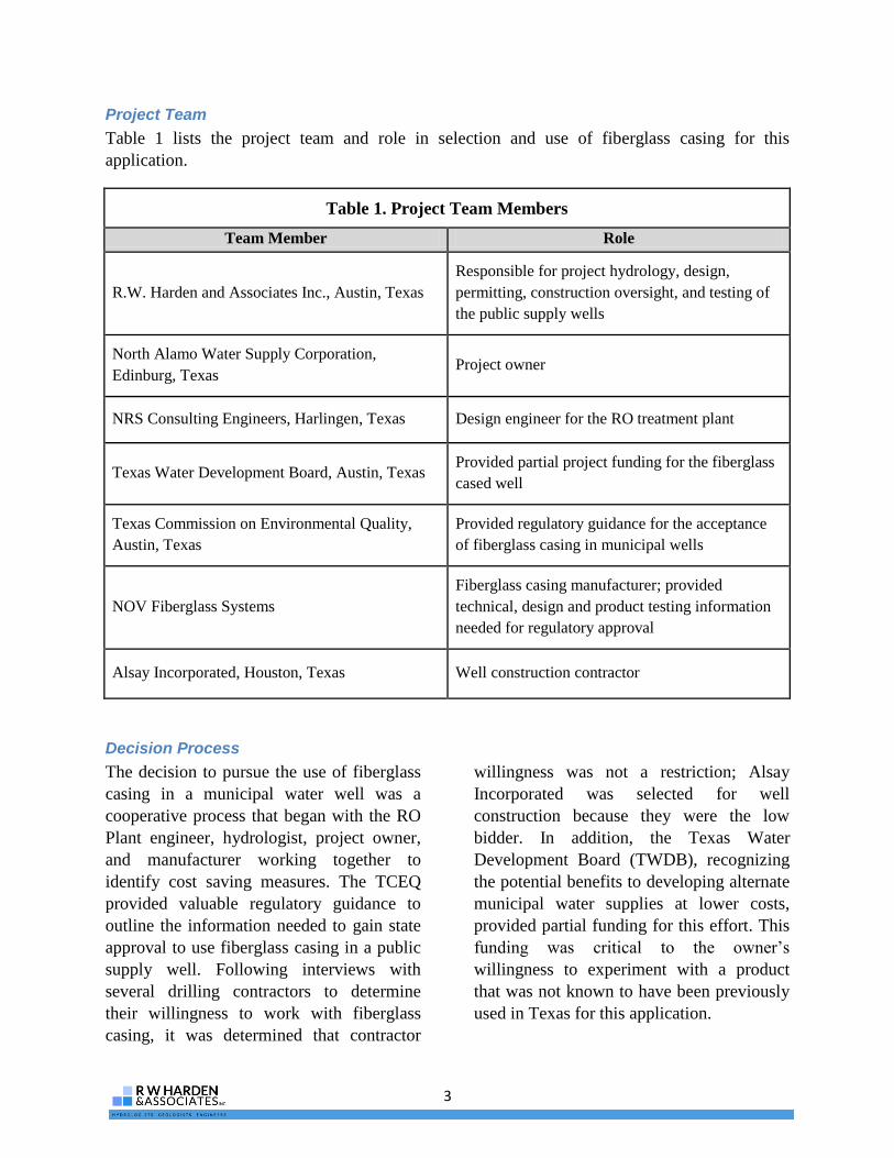
Table 1 lists the project team and role in selection and use of fiberglass casing for this
application.
Table 1. Project Team Members
Team Member Role
R.W. Harden and Associates Inc., Austin, Texas
Responsible for project hydrology, design,
permitting, construction oversight, and testing of
the public supply wells
North Alamo Water Supply Corporation,
Edinburg, Texas Project owner
NRS Consulting Engineers, Harlingen, Texas Design engineer for the RO treatment plant
Texas Water Development Board, Austin, Texas Provided partial project funding for the fiberglass
cased well
Texas Commission on Environmental Quality,
Austin, Texas
Provided regulatory guidance for the acceptance
of fiberglass casing in municipal wells
NOV Fiberglass Systems
Fiberglass casing manufacturer; provided
technical, design and product testing information
needed for regulatory approval
Alsay Incorporated, Houston, Texas Well construction contractor
Decision Process
The decision to pursue the use of fiberglass
casing in a municipal water well was a
cooperative process that began with the RO
Plant engineer, hydrologist, project owner,
and manufacturer working together to
identify cost saving measures. The TCEQ
provided valuable regulatory guidance to
outline the information needed to gain state
approval to use fiberglass casing in a public
supply well. Following interviews with
several drilling contractors to determine
their willingness to work with fiberglass
casing, it was determined that contractor
willingness was not a restriction; Alsay
Incorporated was selected for well
construction because they were the low
bidder. In addition, the Texas Water
Development Board (TWDB), recognizing
the potential benefits to developing alternate
municipal water supplies at lower costs,
provided partial funding for this effort. This
funding was critical to the owner’s
willingness to experiment with a product
that was not known to have been previously
used in Texas for this application.

4
This page left intentionally blank

5
Background
The primary purpose of this manual is to provide guidance to entities considering the use of
fiberglass casing in wells used to produce brackish water for public supplies. Although this
manual primarily focuses on the use of fiberglass casing for brackish groundwater applications,
its application extends to all groundwater, including fresh groundwater that may have corrosive
properties. In general, development of brackish groundwater is only implemented in areas where
other supplies are not available from physical, financial, or regulatory standpoints. Consequently,
it is expected that the use of corrosion-resistant casing material will be concentrated in areas
where brackish water provides a cost-effective source for satisfying future demands. The
following sections provide background information relating to the distribution and availability of
brackish groundwater supplies in Texas, as well as the steps typically required for development
of a municipal well field.
Brackish Groundwater Overview
Depending on the unique circumstances facing a public supply entity, brackish groundwater may
represent an attractive water supply alternative. Typically, there are many combinations of
factors contributing to the desirability of developing brackish supplies. Some of the most
common include: 1) decreasing availability or reliability of surface water supplies, 2) increasing
demand in areas where other groundwater supplies are unavailable, 3) decreased costs due
improvements in treatment processes and/or technologies, 4) inability of current supplies to meet
stricter state drinking water standards, 5) supply diversity and 6) economic considerations of
increasing costs for alternative supplies.
Abundant brackish groundwater resources can be found in most Texas aquifers. However,
because the majority of municipal water suppliers have historically sought fresh groundwater
supplies, data on the quantity of available brackish groundwater resources are generally sparse.
With the exception of portions of southern and western Texas, data regarding the extent and
quality of brackish groundwater resources was, in general, not deliberately sought. Rather,
brackish water information has largely been recorded when brackish water was unintentionally
encountered by those seeking fresh water.
However, there are some “planning tool” levels of information for brackish groundwater supplies
in many areas of Texas. Common examples of available data sources include petroleum industry
geophysical log libraries and reports/maps produced by state agencies such as the TWDB.
Knowing how to access and interpret this information can greatly improve the success (and
reduce the cost) of assessing brackish groundwater availability. Detailed descriptions of the
various data sources and their uses are beyond the scope of this manual; it is recommended that
entities wishing to explore the potential availability of brackish groundwater consult with a
professional hydrogeologist or engineer for guidance.
The productivity and quality of the brackish groundwater resources vary widely and must be
evaluated on a case-by-case basis. Figure 1 shows the general extent and quality of known
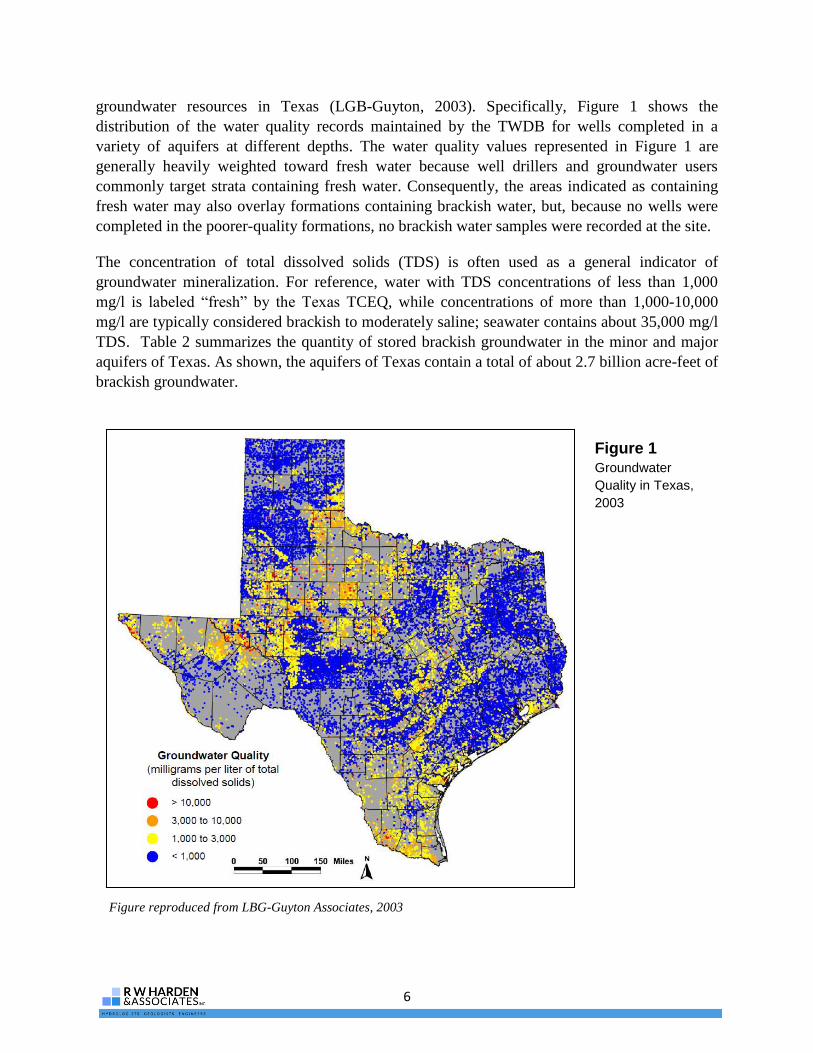
6
groundwater resources in Texas (LGB-Guyton, 2003). Specifically, Figure 1 shows the
distribution of the water quality records maintained by the TWDB for wells completed in a
variety of aquifers at different depths. The water quality values represented in Figure 1 are
generally heavily weighted toward fresh water because well drillers and groundwater users
commonly target strata containing fresh water. Consequently, the areas indicated as containing
fresh water may also overlay formations containing brackish water, but, because no wells were
completed in the poorer-quality formations, no brackish water samples were recorded at the site.
The concentration of total dissolved solids (TDS) is often used as a general indicator of
groundwater mineralization. For reference, water with TDS concentrations of less than 1,000
mg/l is labeled “fresh” by the Texas TCEQ, while concentrations of more than 1,000-10,000
mg/l are typically considered brackish to moderately saline; seawater contains about 35,000 mg/l
TDS. Table 2 summarizes the quantity of stored brackish groundwater in the minor and major
aquifers of Texas. As shown, the aquifers of Texas contain a total of about 2.7 billion acre-feet of
brackish groundwater.
Figure 1
Groundwater
Quality in Texas,
2003
Figure reproduced from LBG-Guyton Associates, 2003

7
Derived from LBG-Guyton Associates, 2003
Table 2. Brackish Groundwater Stored in Texas Aquifers
Aquifer
Volume of Water (acre-feet)
1,000 - 3,000 mg/L
TDS water
3,000 - 10,000 mg/L
TDS water
Total:
1,000 - 10,000 mg/L
water
Major Aquifers
Carrizo-Wilcox 270,024,000 160,157,000 430,181,000
Cenozoic Pecos Alluvium 114,048,000 2,534,000 116,582,000
Edwards-BFZ 14,394,000 24,795,000 39,189,000
Edwards-Trinity (Plateau) 22,383,000 1,968,000 24,351,000
Gulf Coast 352,945,000 167,328,000 520,273,000
Hueco Bolson 24,491,000 0 24,491,000
Mesilla Bolson 480,000 0 480,000
Ogallala 32,731,000 3,494,000 36,225,000
Seymour 2,280,000 0 2,280,000
Trinity 97,451,000 80,714,000 178,165,000
Total 931,227,000 440,990,000 1,372,217,000
Minor Aquifers
Blaine 8,672,000 10,944,000 19,616,000
Blossom 1,089,000 320,000 1,409,000
Bone Spring-Victorio Peak 6,400,000 2,560,000 8,960,000
Capitan Reef 54,333,000 20,375,000 74,708,000
Dockum 59,473,000 65,466,000 124,939,000
Edwards-Trinity (High Plains) 5,750,000 131,000 5,881,000
Ellenburger-San Saba 18,124,000 28,362,000 46,486,000
Hickory 68,898,000 49,213,000 118,111,000
Lipan 1,202,000 48,000 1,250,000
Nacatoch 10,859,000 3,395,000 14,254,000
Queen City-Sparta 167,281,000 78,431,000 245,712,000
Rustler 18,429,000 18,429,000 36,858,000
West Texas Bolsons 6,362,000 0 6,362,000
Whitehorse-Artesia 898,000 16,143,000 17,041,000
Woodbine 17,282,000 26,485,000 43,767,000
Yegua-Jackson 324,864,000 192,993,000 517,857,000
Total 769,916,000 513,295,000 1,283,211,000
8
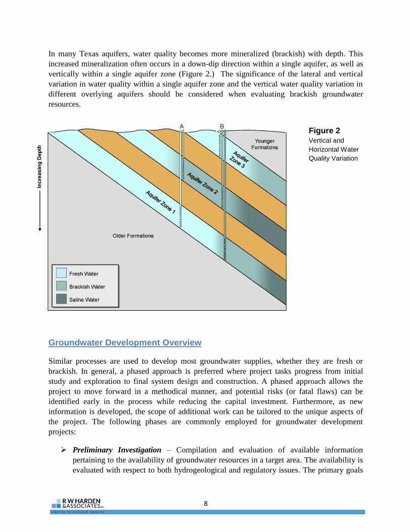
In many Texas aquifers, water quality becomes more mineralized (brackish) with depth. This
increased mineralization often occurs in a down-dip direction within a single aquifer, as well as
vertically within a single aquifer zone (Figure 2.) The significance of the lateral and vertical
variation in water quality within a single aquifer zone and the vertical water quality variation in
different overlying aquifers should be considered when evaluating brackish groundwater
resources.
Groundwater Development Overview
Similar processes are used to develop most groundwater supplies, whether they are fresh or
brackish. In general, a phased approach is preferred where project tasks progress from initial
study and exploration to final system design and construction. A phased approach allows the
project to move forward in a methodical manner, and potential risks (or fatal flaws) can be
identified early in the process while reducing the capital investment. Furthermore, as new
information is developed, the scope of additional work can be tailored to the unique aspects of
the project. The following phases are commonly employed for groundwater development
projects:
Preliminary Investigation – Compilation and evaluation of available information
pertaining to the availability of groundwater resources in a target area. The availability is
evaluated with respect to both hydrogeological and regulatory issues. The primary goals
Figure 2 Vertical and
Horizontal Water
Quality Variation

9
of the study are to identify potential aquifer zones and to estimate long-term groundwater
availability and quality.
Field exploration and study refinement – Assuming the preliminary investigation
indicates a reasonable probability of obtaining groundwater supplies that meet the
quantity and quality requirements for the project, field testing of the aquifer is often
required to obtain site-specific information for the proposed well field. This information
can include: test drilling, aquifer testing, water quality sampling, sand sampling,
geophysical logging, and geophysical studies of the subsurface. This information,
combined with regional information developed in the preliminary investigation, is
frequently combined to create a groundwater model to simulate the aquifer’s response to
long-term pumping.
Well field design – If the results of the previous studies are favorable, a well field design
is developed that includes specific locations for wells, piping, and electrical
infrastructure.
Permitting – In areas of the state where a groundwater conservation district regulates
groundwater pumping, permits are typically required for test drilling, well construction,
and groundwater production.
Final design and Contractor Bidding – After permits are secured for the project, each
well is designed for the specific characteristics of the aquifer at each well location. Upon
completion of the well design, TCEQ approval of the design and well head sanitary
controls is needed prior to well construction. Contractor bidding typically takes place
during TCEQ review as a time-saving measure.
Construction – Upon TCEQ approval to construct, receipt of contractor bids, owner
approval and, if applicable, groundwater conservation district permitting, well
construction is initiated.
Use of Fiberglass Casing in Public Supply Wells in Other States
Currently, fiberglass municipal well casing
is approved in Florida, Nebraska, and
Arkansas. Although other states may not
explicitly approve fiberglass, the exception
process for unconventional municipal well
casing is streamlined and does not pose a
significant hurdle for well construction. The
states which allow fiberglass casing, or have
given exceptions for fiberglass casing are
shown on Figure 3.
Fiberglass public supply well casing is
extensively used in Florida as a substitute
for stainless steel. Companies such as
Burgess Fiberglass, NOV Fiberglass
Systems, and GP Fiberglass are the most
recognized fiberglass casing manufacturers
that have gained approval to install
fiberglass casings in public supply wells.

10
Figure 3
States giving
exceptions for
Fiberglass Wells

11
Why Fiberglass?
Fiberglass pipe can be a practical choice for
various water supply projects where a low-
cost, corrosion-resistant well casing is
required and engineering constraints can be
met. Because it is economical, light-weight,
durable and corrosion-resistant, fiberglass
piping is currently used worldwide as an
alternative to steel or concrete. Fiberglass
has potential benefits in many Texas water
well construction applications due to its low
cost and corrosion resistance as compared to
currently accepted water well materials.
Although not always an appropriate well
material, fiberglass provides a new option
for Texas water well construction projects
that can benefit all parties involved.
TCEQ Approved Casings Material
Design approval and construction methods
for public water supply wells are regulated
in the state of Texas by the TCEQ. The
TCEQ has created rules directing the
construction of public water systems, which
include the materials acceptable in water
well construction. These rules grant
approval for wells constructed using “new
carbon steel, high-strength low-alloy steel,
stainless steel or plastic” that conforms to
American Water Well Association
(AWWA) standards (Texas Administration
Code T30, Chapter 290.41(c)(3)(B)).
Polyvinyl chloride (PVC) is the most
common, and perhaps the only plastic used
in public water systems.
Casing materials that have an AWWA
standard have compositions which
differentiate their use in the water well field:
Carbon Steel – This type of casing is used
predominantly in fresh water wells and is,
by far, the most common public supply well
casing in Texas.
High-Steel Low-Alloy Steel (HSLA) – Rather
than having a defined chemical composition,
HSLA is produced with a goal of attaining
certain mechanical properties. HSLA steel
casing can be formulated to have a moderate
resistance to corrosion and improvements in
strength over carbon steel, allowing it to be
used in deeper wells or wells with mildly
corrosive water. Because the composition of
HSLA is project-specific, delivery times of
HSLA may be longer than carbon or
stainless steel.
Stainless Steel – Composed of at least 50%
iron and at least 10.5% chromium, the
family of stainless steel is quite large and
specialized. There are hundreds of grades
and sub grades, with each designed for a
special application. In the water well
industry, Type 304 and 316L are often used
and can provide corrosion resistance for
wells with moderate salt content and/or
corrosivity, where carbon or HSLA steel
would provide inadequate corrosion
protection. Other types of stainless steel can
provide even greater corrosion resistance in
high chloride and/or low pH environments.
PVC – Composed of polyvinyl chloride
resin, this type of casing is typically used in
shallow wells. It lacks the strength of steel
and is susceptible to further strength
reductions due to the heat of hydration
associated with the curing of cement during
annular sealing.
12
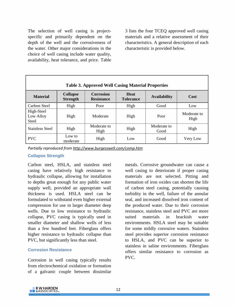
The selection of well casing is project-
specific and primarily dependent on the
depth of the well and the corrosiveness of
the water. Other major considerations in the
choice of well casing include water quality,
availability, heat tolerance, and price. Table
3 lists the four TCEQ approved well casing
materials and a relative assessment of their
characteristics. A general description of each
characteristic is provided below.
Collapse Strength
Carbon steel, HSLA, and stainless steel
casing have relatively high resistance to
hydraulic collapse, allowing for installation
to depths great enough for any public water
supply well, provided an appropriate wall
thickness is used. HSLA steel can be
formulated to withstand even higher external
compression for use in larger diameter deep
wells. Due to low resistance to hydraulic
collapse, PVC casing is typically used in
smaller diameter and shallow wells of less
than a few hundred feet. Fiberglass offers
higher resistance to hydraulic collapse than
PVC, but significantly less than steel.
Corrosion Resistance
Corrosion in well casing typically results
from electrochemical oxidation or formation
of a galvanic couple between dissimilar
metals. Corrosive groundwater can cause a
well casing to deteriorate if proper casing
materials are not selected. Pitting and
formation of iron oxides can shorten the life
of carbon steel casing, potentially causing
turbidity in the well, failure of the annular
seal, and increased dissolved iron content of
the produced water. Due to their corrosion
resistance, stainless steel and PVC are more
suited materials in brackish water
environments. HSLA steel may be suitable
for some mildly corrosive waters. Stainless
steel provides superior corrosion resistance
to HSLA, and PVC can be superior to
stainless in saline environments. Fiberglass
offers similar resistance to corrosion as
PVC.
Table 3. Approved Well Casing Material Properties
Material Collapse
Strength
Corrosion
Resistance
Heat
Tolerance Availability Cost
Carbon Steel High Poor High Good Low
High-Steel
Low Alloy
Steel
High Moderate High Poor Moderate to
High
Stainless Steel High Moderate to
High High
Moderate to
Good High
PVC Low to
moderate High Low Good Very Low
Partially reproduced from http://www.burgesswell.com/comp.htm

13
Figure 4 GreenThread
Filament Winding
Process
Heat Tolerance
The curing of cement-based annular grouts
is an exothermic reaction and can produce
temperatures that can weaken some well
casing materials. Although the increased
borehole temperatures are generally not a
problem for steel which maintains its
strength at temperatures encountered during
the curing of cement grouts, PVC begins to
weaken at temperatures above 75° F. Some
well construction methods can help mitigate
this loss of strength, but without detailed
information on down hole temperatures, the
use of PVC should include a significant
safety factor, and/or preventive measures to
reduce casing temperatures during cement
curing. Although fiberglass also loses
strength with heat, its tolerance to heat is
significantly better than PVC.
Availability
While carbon steel, stainless steel and PVC
are typically available in a period of days (or
perhaps weeks in the case of stainless steel),
HSLA can take weeks to become available
due to specific formulations for individual
projects. Fiberglass availability may require
long lead times for construction because it is
constructed for a specific application. While
the ability to custom order well casing can
reduce cost, it requires careful planning.
Cost
Well material costs have maintained
consistent relationships, with PVC being
lowest, followed by carbon steel, HSLA,
and stainless steel. Type 316 stainless steel,
the most corrosive resistant of commonly
used steel casing materials, can cost 8 to 10
times more than carbon steel depending on
current metal prices which can be volatile.
Fiberglass is typically more expensive than
carbon steel, but significantly less than
stainless steel, with prices tied to current
world oil prices.
Fiberglass Well Casing
NOV Fiberglass Systems Fiberglass
GreenThread piping is specially constructed
of a glass reinforced epoxy (GRE) resin
material. The resin is a thermosetting
aromatic amine-cured epoxy reinforced with
continuous glass fibers. The GreenThread
structure is created by a filament winding
process, where resin-impregnated glass
fibers are wound onto a mandrel in a
predetermined pattern under a controlled
tension (Figure 4). Keyed couplings and
fiberglass adapters are used to join lengths
of pipe.
Aromatic amine cured epoxies have superior
temperature resistance in water applications
over other types of epoxies and particularly
vinyl ester thermosetting resins. This epoxy
system does not use styrene as a diluent like
vinyl esters and coupled with the heat curing
Figure courtesy of NOV Fiberglass Systems

14
process allows for compliance with the NSF
Standard 61 for drinking water applications.
Product data for GreenThread pipe can be
found in Appendix A.
Fiberglass Potential Use
GRE fiberglass piping has an abundance of
potential uses due to its durability, chemical
resistance, and relatively low costs. From its
inception in the 1950’s, fiberglass piping has
been used extensively in oil and water
production. In Texas, fiberglass piping has
been used for hot brine transmission, brine
injection, chemical disposal and geothermal
applications. The state of Florida has
allowed uses such as aquifer recharge
injection, deep well applications, and public
water supply. Florida, Nebraska and
Arkansas regulations specifically address
fiberglass for use in public water supply
applications as well (Appendix B).
Fiberglass Advantages and
Disadvantages
Utilized in water well applications,
fiberglass has a number of advantages over
carbon steel, stainless steel and PVC casing.
Favorable cost and superior corrosion
resistance are the primary benefits when
choosing fiberglass over other common
casing materials, however, ease of
installation and material weight are
additional benefits that a potential user may
consider. A comparison between fiberglass
and HSLA pipe is not provided, because of
the variability of composition of HSLA and
its limited use in Texas public supply wells.
Fiberglass vs. PVC
The principal advantages of GRE fiberglass over PVC are:
Superior strength at deeper settings and larger casing diameters
Superior durability during transport and installation
Less susceptible to abrasion from pumping equipment vibration
Superior resistance to heat
The principal disadvantages of GRE fiberglass over PVC are:
Higher cost
Availability
Ease and time required for permitting
Fiberglass vs. Carbon Steel
The principal advantages of GRE fiberglass over carbon steel are:
Highly superior corrosion resistance (Appendix C)
Typically faster and easier installation
More stable pricing

15
The principal disadvantages of GRE fiberglass over carbon steel are:
Higher cost
Availability
Ease and time required for permitting
Requires specialized handling
Partial loss of strength due to heat
Significantly less resistance to hydraulic collapse
Fiberglass vs. Stainless Steel
The principal advantages of GRE fiberglass over stainless steel are:
Lower cost
Superior corrosion resistance (Appendix C)
Typically faster and easier installation
More stable pricing
The principal disadvantages of GRE fiberglass over stainless steel are:
Availability
Ease and time required for permitting
Requires specialized handling
Partial loss of strength due to heat
Significantly less resistance to hydraulic collapse
Further information on these advantages and disadvantage is detailed in the case study provided
in this guidance manual.
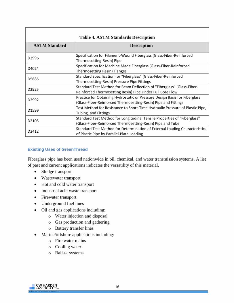
Fiberglass Certifications
NOV GreenThread fiberglass is designed and constructed based on the ASTM D2996, D4024,
D5685, and D2925 standard specifications. The pipe is tested based on ASTM D2992, D1599,
D2105, and D2412 standard test methods (Table 4). The casing, fittings, couplings, and joining
and sealing materials used in NOV fiberglass systems have been approved for drinking water
applications and are in compliance with NSF/ANSI Standard 61. The general specifications and
certifications for GreenThread pipe can be found in Appendices D & E. For NSF 61 standards
publications please visit www.nsf.org.
16
Table 4. ASTM Standards Description
ASTM Standard Description
D2996 Specification for Filament-Wound Fiberglass (Glass-Fiber-Reinforced Thermosetting-Resin) Pipe
D4024 Specification for Machine Made Fiberglass (Glass-Fiber-Reinforced Thermosetting Resin) Flanges
D5685 Standard Specification for "Fiberglass" (Glass-Fiber-Reinforced Thermosetting-Resin) Pressure Pipe Fittings
D2925 Standard Test Method for Beam Deflection of "Fiberglass" (Glass-Fiber-Reinforced Thermosetting Resin) Pipe Under Full Bore Flow
D2992 Practice for Obtaining Hydrostatic or Pressure Design Basis for Fiberglass (Glass-Fiber-Reinforced Thermosetting-Resin) Pipe and Fittings
D1599 Test Method for Resistance to Short-Time Hydraulic Pressure of Plastic Pipe, Tubing, and Fittings
D2105 Standard Test Method for Longitudinal Tensile Properties of "Fiberglass" (Glass-Fiber-Reinforced Thermosetting-Resin) Pipe and Tube
D2412 Standard Test Method for Determination of External Loading Characteristics of Plastic Pipe by Parallel-Plate Loading
Existing Uses of GreenThread
Fiberglass pipe has been used nationwide in oil, chemical, and water transmission systems. A list
of past and current applications indicates the versatility of this material.
Sludge transport
Wastewater transport
Hot and cold water transport
Industrial acid waste transport
Firewater transport
Underground fuel lines
Oil and gas applications including:
o Water injection and disposal
o Gas production and gathering
o Battery transfer lines
Marine/offshore applications including:
o Fire water mains
o Cooling water
o Ballast systems

17
Selection of Casing Material
The following sections describe the engineering calculations and water chemistry considerations
used in the selection of well casing. Resistance to hydraulic collapse pressure (RHCP) during
cement grouting operations and water quality are the primary considerations used to narrow
casing material options. The design phase provides an opportunity to evaluate strengths and
properties of the casing under site-specific conditions.
Corrosiveness can be an imprecise evaluation because of the complex chemical reactions. It is
often useful to evaluate the physical properties of the casing for its suitability to the application
prior to conducting studies of the materials’ suitability for the water quality. The main physical
forces imposed on casing during well installation are horizontal and tensile loading. Of these
physical forces, horizontal loading during cementing operations is typically the most limiting to
the selection of casing material. While it is recommended that tensile loads be calculated, it is
uncommon for it to be a significant limiting factor.
Horizontal and tensile loads are only critical during well construction due to the dynamic
conditions encountered when setting and cementing the casing.
Resistance to Hydraulic Collapse Pressure
Resistance to hydraulic collapse (RHCP) is the casing’s ability to resist external pressures that
result from differential fluid densities during cementing operations. Collapse strength for a
specific casing is determined by wall thickness, diameter, and structural properties of the
material (Yield strength, Young’s modulus and Poisson’s ratio). Casing wall thickness and
diameter are the two controllable design parameters that are most critical.
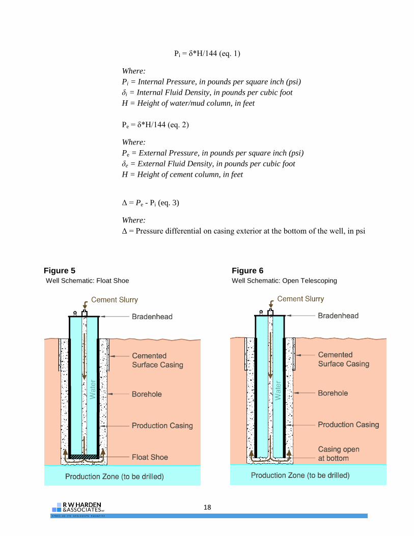
During emplacement of cement grout in the annulus, an AWWA-approved cement is pumped
from the bottom of the casing until it appears at the surface on the exterior of the well. In
telescoping under-reamed well designs (Figures 5 and 6), tubing is installed to the base of the
casing, the inside of the casing is filled completely with drilling mud or clear water and the top
of the casing is sealed at the surface. During the cementing process shown on Figure 5 (AWWA
Standard 100-06, Appendix C.6) the fluid column on the outside of the casing (cement grout) is
isolated from the fluid on the inside of the casing (water or drilling mud) with a float shoe. A
float shoe is a valve that only allows fluid to flow in one direction. Because the cement on the
outside of the casing is heavier than the mud/water in the inside of the casing, external pressure
on the casing is created. The fluid pressure differential is greatest at the bottom of the casing and
must not exceed the RHCP rating of the casing. Down hole pressure inside and outside of the
casing is calculated as:
18
Pi = δ*H/144 (eq. 1)
Where:
Pi = Internal Pressure, in pounds per square inch (psi)
δi = Internal Fluid Density, in pounds per cubic foot
H = Height of water/mud column, in feet
Pe = δ*H/144 (eq. 2)
Where:
Pe = External Pressure, in pounds per square inch (psi)
δe = External Fluid Density, in pounds per cubic foot
H = Height of cement column, in feet
Δ = Pe - Pi (eq. 3)
Where:
Δ = Pressure differential on casing exterior at the bottom of the well, in psi
Figure 5
Well Schematic: Float Shoe
Figure 6
Well Schematic: Open Telescoping
19
The cementing process shown on Figure 6 (AWWA Standard 100-06, Appendix C.4) is identical
to the process described for Figure 5 with the exception of the float shoe. In figure 6, the bottom
of the casing is open to the annulus without the benefit of a valve that prevents fluid from
flowing back into the casing. The risk in cementing using this method is that if the seal between
the cement tremie line and the bradenhead is compromised, the heavier cement on the outside of
the casing will displace the water on the inside of the casing – which would be leaking out the
compromised seal – and the cement will set up on the inside of the casing and the annular seal
will not extend the entire length of casing. The advantages of using this method is the fluid
pressures inside and outside the casing are roughly equal at the bottom of the casing, and there is
an outward pressure at the top of the casing. Burst pressure ratings for well casing is typically
greater than collapse pressure ratings and is generally not a concern in shallow applications. The
cementing process shown on Figure 6 is only recommended for relatively shallow casings where
there is certainty that the outward pressure can be adequately contained by the seal between the
cement tremie line and the bradenhead.
In straight wall designs (Figure 7), equation 3 is also used to calculate the external pressure on
the casing. It is important to note that the top of the well is not sealed and the fluid column height
inside the casing may not extend to the surface. This is especially critical when using PVC
casing because there may not be an internal fluid inside the casing to provide outward pressure
and to dissipate the heat generated during cement curing. Adding water or weighted fluids to fill
the casing can help add internal pressure and dissipate heat. However, because the mud/water on
the inside of the casing is open to the formation - through the screen - fluid losses may be
expected. Therefore, it is critical that the internal fluid levels are maintained until the cement has
cured. Fluid loss to the formation may make well development more difficult. When cementing
straight wall wells, a tremie pipe is placed very near the top of the gravel pack and pumped from
the surface (AWWA Standard 100-06, Appendix C.3). The cement surrounds the casing and
displaces the fluid until cement appears at the surface (Figure 7).
The result obtained from equation 3 is then compared to the published or calculated RHCP for
the intended casing. Calculating RHCP for fiberglass and PVC casing is more difficult than steel
because the manufacturers use proprietary formulations of their product that make it difficult or
impossible to verify their RHCP rating. Carbon and stainless steel are standard formulations and
yield strength, Young’s modulus, and Poisson’s ratio are known values. If a custom wall
thickness pipe will be considered, then working with the fiberglass manufacturer at this stage in
the design process is important.

20
Table 5 shows sample pressures and pressure differential on a casing at various cement well
depths. It is important to note that the fluid densities may be different depending on the grout
mixture and internal fluid density. Flexible bentonite grouts are not permitted on public supply
wells under current TCEQ rules.
Figure 7 Well
Schematic:
Straight
wall

21
Table 5. Pressure on Base of Well Casing Exerted During Cementing Process
Density of
Cement (lbs/ft3)
Height of
Cement Outside
Casing (ft)
Density of Water
(lbs/ft3)
Height of Water
Inside Casing (ft)
Pressure
Differential at
Casing Base (psi)
101* 100 62.4 0 70
101* 100 62.4 100 27
101* 200 62.4 200 53
101* 500 62.4 500 134
101* 1000 62.4 1000 268
101* 1500 62.4 1500 402
101* 2000 62.4 2000 536
117** 2000 62.4 2000 758
*Portland Cement with 6% Bentonite
**Portland Cement with 0% Bentonite
A direct comparison between RHCP values for the casing materials discussed in the guidance
manual cannot be made because collapse pressure for steel is calculated from the physical
properties of the steel, while fiberglass and PVC RHCP values are provided by the manufacturer
and include a safety factor. The engineer must decide on an appropriate safety factor for steel
casing. For carbon steel, stainless steel, and PVC, RHCP ratings increase with larger wall
thicknesses and smaller diameters. For fiberglass, wall thickness has a greater effect on RHCP
rating than diameter, because of the internal structure (fibers) and angle at which the fibers are
wrapped.
Tensile Strength
During well construction, the casing – or casing and screen in straight wall wells - is suspended
in the borehole as each casing piece is joined to the next. Gravity exerts a tensile load over the
length of the casing, and is greatest at the surface. Typically, the borehole is filled with water or
drilling mud, therefore the casing material has buoyancy that will counterbalance the weight of
the casing string. The tensile load is the difference between the weight of the casing and its
buoyancy given by equation 4:
22
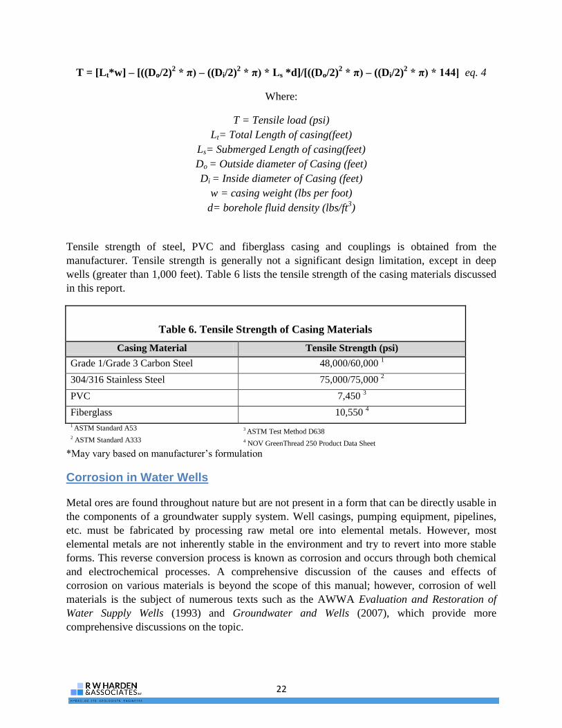
T = [Lt*w] – [((Do/2)2 * π) – ((Di/2)
2 * π) * Ls *d]/[((Do/2)
2 * π) – ((Di/2)
2 * π) * 144] eq. 4
Where:
T = Tensile load (psi)
Lt= Total Length of casing(feet)
Ls= Submerged Length of casing(feet)
Do = Outside diameter of Casing (feet)
Di = Inside diameter of Casing (feet)
w = casing weight (lbs per foot)
d= borehole fluid density (lbs/ft3)
Tensile strength of steel, PVC and fiberglass casing and couplings is obtained from the
manufacturer. Tensile strength is generally not a significant design limitation, except in deep
wells (greater than 1,000 feet). Table 6 lists the tensile strength of the casing materials discussed
in this report.
Table 6. Tensile Strength of Casing Materials
Casing Material Tensile Strength (psi)
Grade 1/Grade 3 Carbon Steel 48,000/60,000 1
304/316 Stainless Steel 75,000/75,000 2
PVC 7,450 3
Fiberglass 10,550 4
1 ASTM Standard A53 3 ASTM Test Method D638 2 ASTM Standard A333 4 NOV GreenThread 250 Product Data Sheet
*May vary based on manufacturer’s formulation
Corrosion in Water Wells
Metal ores are found throughout nature but are not present in a form that can be directly usable in
the components of a groundwater supply system. Well casings, pumping equipment, pipelines,
etc. must be fabricated by processing raw metal ore into elemental metals. However, most
elemental metals are not inherently stable in the environment and try to revert into more stable
forms. This reverse conversion process is known as corrosion and occurs through both chemical
and electrochemical processes. A comprehensive discussion of the causes and effects of
corrosion on various materials is beyond the scope of this manual; however, corrosion of well
materials is the subject of numerous texts such as the AWWA Evaluation and Restoration of
Water Supply Wells (1993) and Groundwater and Wells (2007), which provide more
comprehensive discussions on the topic.

23
Identifying the Potential for Corrosion
Use of plain carbon steel for well construction materials is widespread in the industry. In many
cases, plain carbon steel provides the best cost/benefit considering material strength, operating
conditions, and life of the material. In other cases, corrosion is severe and unsatisfactory life is
experienced. To address this, the native groundwater quality must be considered to select the
well construction material best suited for both the corrosion potential (material life) and required
design strength.
Water Quality Considerations
Groundwater quality can be an indicator of the potential for corrosion of well casing. Some of
the more important parameters include pH, chloride, total dissolved solids, and dissolved gases.
Table 7 lists these indicators and their particular concern relative to corrosion.
Table 7. Common Corrosion Related Constituents in Texas Groundwater
Indicator Remarks
pH
A measure of the concentration of hydrogen ions in water. Indicates
whether water is acidic or basic. Acidic water (pH<7) is generally
considered to be corrosive
Total Dissolved Solids
(TDS)
TDS is a general indicator of the concentration of dissolved ions that
may contribute to corrosion
Dissolved Oxygen
(DO)
In general, greater concentrations of dissolved oxygen indicate
increased corrosiveness of groundwater
Sulfide (S-2
) Highly corrosive if present as hydrogen sulfide 1
Carbon Dioxide (CO2)
Carbon dioxide reacts with water to form carbonic acid, which
increases groundwater acidity and corrosivity
Chloride (Cl-) Corrosive in concentrations greater than 200 mg/L
2
1 Hem, 1992
2 Groundwater and Wells, 2007
Groundwater with a pH of 7.0 is considered to be neutral, while a pH below 7 is considered
acidic and a pH above 7 is considered to be alkaline or basic. In general, acidic groundwater
accelerates corrosion, while alkaline waters will tend to promote the precipitation of solids
thereby providing protection against corrosion. The pH that corrosion will occur is related to
both the chloride content of the water and the temperature. In general, there is a greater
probability of corrosion under higher the temperature and chloride concentration, and lower pH
environments. A pH of less than 4 is highly corrosive, but even groundwater with pH above 7
can be corrosive.
Gases such as oxygen, carbon dioxide, and hydrogen sulfide may be dissolved into groundwater
and can increase the potential for corrosion. Oxygen and carbon dioxide (CO2) enter
groundwater through interaction with the atmosphere or through dissolution of formation
materials through chemical processes. Hydrogen sulfide (H2S) is formed when sulfate reduction

24
activity, usually in form of bacteria, occurs in groundwater stemming from interactions with
petroleum or decaying organic matter.
Galvanic Corrosion
In addition to corrosion facilitated by groundwater quality, there are material compatibility
considerations that can affect well life. When two adjacent metals of different compositions are
placed in an electrolyte solution, an electric potential is created, incurring a current flow.
Corrosion occurs as electrons are lost from the active metal (anode), which oxidizes and
dissolves, releasing positive ions that travel through the electrolyte solution to a less reactive
metal (cathode). Galvanic corrosion is dictated by the passive and active properties of two
adjoining metal alloys (Groundwater and Wells, 2007). Carbon steel and iron are active metals
and will readily corrode when in contact with a less reactive metal. Stainless-steel is an alloy that
combines iron with other metals that are less reactive and will generally act as a cathode in the
galvanic process.
Material Selection
The choice of material selection in well construction should consider the potential for corrosion,
the service conditions, life expectancy, and economics. To address corrosion, there are several
options:
Use of protective coatings such as epoxy paint,
Protective films produced on surfaces by chemical reactions,
Application of electrical potential to equipment, or
Selection of more corrosion resistant material.
Careful consideration of the operating environment desired service life and cost leads to the
material best suited for its application.

25
Case Study - NAWSC Donna Project
The following sections provide a summary of the milestones achieved in the construction of a
fiberglass-cased public supply well. While some of these milestones are routine for many
groundwater supply projects, there were several challenges that needed to be overcome. The
intent of this section is to highlight some of the differences and planning required to utilize a new
well construction material. Where appropriate, a “lesson learned” note is provided.
Owner Involvement
The development of this project began with a request from the project owner, NAWSC, to
identify ways to reduce the construction cost of developing a brackish groundwater project. The
RO treatment plant project engineers, NRS Consulting Engineers, and the groundwater
hydrologists/engineers, R.W. Harden and Associates, Inc. identified alternate well casing
materials as a potential cost saving measure that had the potential to increase well life. Fiberglass
was suggested as a strong candidate because of its strength and corrosion resistant properties.
NOV Fiberglass Systems was chosen as a potential supplier of well casings based on their
experience with oil field well casings, their involvement in supplying fiberglass pipe for the RO
treatment plant, and their willingness to adapt an existing product for a new use.
Willingness of the owner to accept the risk for trying new methods and materials and
manufacturer’s ability to provide testing data and design drawings for a re-purposed product
proved to be a time-consuming process. Other manufacturers of fiberglass casing for water wells
were not available in the diameter (24 inches) needed for the project. The immediate need for
additional water supplies during a period of drought for
an owner with a rapidly growing number of customers
resulted in several projects that had short time schedules.
Fiberglass casing had been considered for three other
projects since 2004, but the project schedules did not
allow sufficient time to work through the design issues.
The time required to fully evaluate the casing and obtain
TCEQ approval for its use were all significant obstacles
in the implementation of the plan.
NRS Consulting Engineers, the lead design engineer for
the project worked with the owner to anticipate future
growth and initiate projects prior to immediate need was
key to implementing the use of fiberglass casing. A brief
relief from drought conditions coupled with the prior
work that was conducted to investigate the use of
fiberglass well casing allowed the project team to
implement a schedule that was workable.
Lesson Learned:
The implementation of new
well designs and construction
materials requires a
significant amount of time.
Identifying long-term
demands and prior planning
were critical to providing an
opportunity for the owner to
explore the use of methods
and materials that are more
cost effective and are likely to
provide a longer service life.

26
Preliminary Considerations
Fiberglass is an ideal product for use in brackish or corrosive water environments if water quality
is the only consideration; it may not be the best casing material for all projects. Initially, casing
material selection was explored based on the needs of the project. State-approved casing
material, water quality, engineering limitations, NSF certification and budget were all considered
prior to selection of casing material.
Based on aquifer evaluations of the project site, a preliminary engineering investigation of the
well design was conducted to explore horizontal and vertical loads on the casing during
installation and well use, and to verify with the manufacturer that the product could meet the
basic strength requirements.
Cost and corrosion resistance were the principal arguments in favor of fiberglass casing over
stainless steel casing. HSLA steel was considered but was likely to have an unacceptable service
life for the project based on water quality. PVC was also considered, but uncertainty about its
resistance to hydraulic collapse when using cement-based annular well grouts - due to unknown
borehole temperatures resulting from the heat of hydration during cement curing - at the depths
required resulted in an unacceptable risk for the owner. Fiberglass casing provided an acceptable
balance between the high cost of stainless steel, the high potential for corrosion with HSLA steel,
and the high risk of PVC casing collapse.
The principal challenge was to identify a product that met the engineering requirements of the
project. The most significant were resistance to hydraulic collapse and indentifying a method to
join each joint of casing in a reasonable period of time. Joining of fiberglass pipe typically
involves application of epoxy resins that must be fully cured prior to submergence, and could
take up to one hour per casing joint connection. This is particularly a concern in unconsolidated
geologic formations where borehole stability is marginal and installation of casing and cement
are time-critical.
The process for evaluating each casing material is provided in the previous section of this
guidance manual. To address concerns about hydraulic collapse and developing a coupling
system involved a number of conversations and communication with the manufacturer.
Ultimately, the pipe used was custom manufactured for this application and tested to provide
evidence that the resistance to hydraulic collapse was acceptable. Appendix F is a certification
from the manufacturer that the well casing will meet the project requirements. Appendix G is
engineering drawings of the coupling developed to join the casing. The coupling system includes
adapters that are joined to the casing at the manufacturing plant, a coupling to join the adapters, a
rubber gasket to ensure a water-tight seal, and a flexible spline that fits into opposing grooves in
both the coupling and adaptor.

27
Selection of Material Supplier
Potential suppliers were identified through web searches and phone conversations with fiberglass
pipe suppliers and drilling companies in other states to identify potential suppliers. Because no
purpose-specific, 24-inch diameter, fiberglass casing was available, it was immensely helpful to
indentify a manufacturer (NOV Fiberglass Systems), who was willing to modify their existing
products to meet the needs of this project. Twenty-four inch, NSF certified pipe was a product
that was already manufactured, but designing a field coupling method that could be uncoupled
and re-coupled – in the event the casing got stuck in the hole – without having to return the
casing to the manufacturing plant to be refitted with new couplings was a time consuming
process. Therefore, the principal challenge was to indentify a method to join the pipe in an
amount of time that would not risk borehole integrity and could be disassembled and rejoined in
a short period of time, if needed.
Numerous meetings and phone conversations were held to identify the issues and develop a
coupling that the manufacturer had the ability to fabricate and met the project requirements.
NOV Fiberglass Systems expressed a willingness to work with the project engineers to develop a
product that could be used in a water well application.
Preliminary Regulatory Meetings
Initial inquiries with TCEQ regarding the use of fiberglass casing yielded conflicting answers to
the question of whether or not an exception would be considered. At issue was the absence of an
AWWA standard for fiberglass casing and that TCEQ policy was to only allow casing which had
an AWWA standard in public supply wells. These initial phone conversations occurred in the
first few years after fiberglass was identified as a potentially beneficial product for brackish
groundwater wells. Years later, when a project that had a workable timeline was identified, a
face-to-face meeting with TCEQ staff was conducted to explain the project and potential
benefits. TCEQ staff members were attentive, asked many questions and agreed to consider an
exception.
An exception submittal was prepared that detailed the engineering calculations, NSF
certifications, and general product information. The level of information required by TCEQ was
significantly more than was originally anticipated. However, none of the information requests
were unreasonable and a face-to-face meeting allowing senior staff to ask questions and listen to
the proposal was a major milestone in reaching an understanding of the project. Initially TCEQ
estimated that the exception review process would take 180 days. Actual approval was granted in
about 100 days.
Selection of Casing Materials
The methods described in this guidance manual were used to evaluate the project design needs
and the casing used. Because this project required two wells, it offered an opportunity to conduct
a direct comparison between two wells with similar dimensions, one with stainless steel casing
28
and one with fiberglass casing. There were six principal considerations in the evaluation of the
fiberglass casing:
corrosion resistance,
resistance to hydraulic collapse,
attaching a well head flange at the top of the casing,
casing diameter,
developing a way to join the casing in the field, and
reducing the amount of cement grout that remains in the casing after cementing is
complete.
The following sections describe each of these considerations and how each was addressed.
Corrosion Resistance
Water samples taken from two test wells at the site indicated a total dissolved solid concentration
of about 4,500 mg/L. The high salt concentration limited the production casing to materials
having high corrosion resistance. It is widely known that PVC and fiberglass are nonreactive in
salt solutions having a pH that is close to neutral.
Fiberglass and stainless steel were both proposed as possible well casing materials due to their
corrosion resistance and applicability to the site specific conditions. PVC was also considered,
but rejected because, at the time, it was not available in the size needed for the project, its
collapse strength properties were not likely to be sufficient for the 240 foot depth setting
required, and it is not a preferred material for telescoping well designs due to the risk of casing
damage when re-entering the hole to drill the production zone. Carbon steel was not considered
due to its low corrosion resistance. Stainless steel was an obvious choice as a standard material
and was used in one well. Fiberglass was chosen as the material for the second well as the risks
involved in using this new material could be mitigated and were outweighed by potential cost
savings.
Resistance to Hydraulic Collapse
Using the standard float shoe method of cementing, it was determined that en external force at
the bottom of the casing would be 65 pounds per square inch (psi). Published literature for the
Green Thread 250 pipe indicates an ultimate collapse pressure of 175 psi and a rated collapse
pressure of 55 psi. The rated collapse pressure includes a very conservative safety factor of 3.0
(Appendix A). These collapse pressure ratings are calculated based on the properties of the pipe.
NOV Fiberglass Systems conducted laboratory testing of the casing and was able to provide a
collapse pressure rating of 79 psi (Appendix F). Due to uncertainty about down hole temperature
during cement curing and its affect on the rated collapse pressure, it was decided to avoid the
collapse pressure issue and cement the well without a float shoe using AWWA A100-06 standard
C.4. In this method, the cement and interior fluid columns are connected and the down hole
pressure on both sides of the casing are equal. However, an internal pressure is created at the top
29
of casing which requires that the seal between the cement tremie pipe and the bradenhead be
flawless. The contractor, Alsay Inc., confirmed that they were able to provide such a seal. The
internal pressure rating of the casing is 250 psi which is more than three times the expected
internal pressure at the bradenhead. A pressure gauge was installed on the bradenhead to monitor
internal casing pressure.
Well Head Flange
The manufacturer designed and constructed a well head flange at the top of the upper casing joint
that was capable of supporting the weight of the motor, column pipe full of water, pump and
pump drive shaft. The flange was pre-drilled with bolt holes to attach the flanged well head
sealing plate. A rubber gasket was installed between the flanges to form a water tight seal as
required by TCEQ regulations.
Casing Diameter
Typically, casing diameter is selected based on well productivity and the size of the pump that
needs to be installed. After the casing is installed and cemented, the screened interval is under-
reamed to a diameter that is larger than the casing. Because the aquifer production zone is
composed of unconsolidated gravel, cobbles and sand, drilling contractors have been hesitant to
use an under-reamer for fear that it will not close after drilling if a piece of gravel gets lodged in
the arms of the under-reamer, thereby preventing the under-reamer from being recovered from
the hole. Because the top of production zone was relatively shallow (240 feet), an alternative
telescoping well design was considered where the production zone is reamed using a standard
drill bit. With a 24-inch casing (23.25-inch inner diameter for stainless steel pipe), the screened
interval could be reamed to 22-inches with a standard drill bit and easily removed from the hole.
Fiberglass casing would present a challenge for under-reamed holes because the under-reaming
bit is typically closed by pulling – sometimes banging - up on the bottom of the casing. This is
not an issue for steel casing, but it may be possible to damage fiberglass casing if the drilling
contractor has difficulty closing the under-reamer.
Fiberglass Couplings
Couplings for the fiberglass casing were manufactured specifically for this application and
manufactured with necessary dimensions to fit over the casing and with ample strengths to
withstand loads exerted by the suspended casing string. Appendix G shows dimensions, in
millimeters, for the coupling system of a 24’’GreedThread 250 casing. The outside diameter of
the joining coupling is about 29.5 inches, which is about 4 inches larger than the outside
diameter of the casing.
To attach the coupling on each end of the casing, and to ensure a seal, a joining system was
designed. The custom coupling system consists of two fiberglass adapter sleeves bonded to each
end of a pipe joint, then joined end to end by the coupling. Joining and sealing adhesive is
applied to the mating surfaces before the adapters are installed. During casing installation, the

30
coupling slides over an O-ring on each adapter and a key, or spline, is fed through a circular
groove between the adapter and coupling.
It was necessary for each component of the coupling system to have ample strength to comply
with collapse and tensile requirements as well as form a watertight seal to prevent cement from
leaking into the casing. Strength of the system depends on the adhesive bond shear strength, key
shear strength and joint strength. For bonded adapters, joint strength is based on the bond area
and adhesive strength applied at the manufacturing plant.
Table 8 lists engineering specifications for the 24” fiberglass casing adapters and couplings.
Cross sectional area and shear strength of key material was used to calculate keyed coupling
tensile strength. Because the casing was cemented in place, loads on the casing and couplings are
short term and are only applied when the cement grout is in a liquid state.
Table 8. Strength of GreenThread 250 Coupling System
Bonded Adapter
Casing Diameter (in) 24
Bond Length (in) 10.6
Allowable Short Term Shear Strength (psi) 500
Allowable Short Term Joint Strength (lbs) 417,304
Keyed Coupling
Casing Diameter (in) 24
Shear Plane Diameter (in) 27.165
Key Diameter (in) 0.591
Shear Area (in) 50.4
Allowable Short Term Key Shear Strength (psi) 4,800
Allowable Short Term Joint Strength (lbs) 241,915
If fiberglass casing is to be used in straight wall applications, a method for attaching the casing to
a stainless steel, wire-wrapped screen must be developed. Although this design was not
considered for this project and not thoroughly investigated, possible options include: 1)
fabrication of a stainless steel adapter that mates to the fiberglass coupling described above, 2)
sending the upper joint of stainless steel screen to the fiberglass manufacturer so that it can be
bonded at the fiberglass plant using a wrapped joint, and 3) use of mill-slotted fiberglass screen.
All of these methods require that the exact setting depth of the screen and casing be known prior
to construction. Mill-slotted screens are not preferred in large capacity public supply wells, due
to their smaller amount of open area and potential for constructing low-efficiency wells.

31
Reducing Amount of Cement in the Casing
Because there is typically a few to several feet of cement remaining in the bottom of well casings
which must be drilled out, there was concern that drilling out this remaining cement would
damage the bottom of the casing. In an effort to mitigate this concern, the cement tremie line was
installed to the same depth as the casing, and the casing was completely filled with water prior to
sealing the bradenhead. A slug of fresh water that was the exact volume of the tremie pipe and
cement hoses followed the cement after a cement return appeared at the surface on the outside of
the casing.
Regulatory Submittals and Approval for Use
Fiberglass is currently not permitted as a well casing material in Texas. Texas Administrative
Code (TAC) does not allow for casing material other than those approved by the AWWA
standards (TAC Title 30, Chapter 290.41(c)(3)(B)). The following items were submitted in
support of the exception request:
Well Specifications
Design drawings of the well
Manufacturer information on the engineering properties of the casing
NSF certifications for the casing and couplings
Calculations showing the tensile and collapse forces exerted on the casing
Florida and Nebraska Regulations
concerning fiberglass casing in public supply
wells
Appendix H includes the exception request letter
submitted to the TCEQ by RWH&A and TCEQ’s
approval letter.
Cost Evaluation
Designing both wells concurrently allowed
RWH&A to compare prices of stainless steel and
fiberglass in nearly identical well designs at a single
point in time, and having a nominal casing length of
247 feet. Table 9 shows the prices for stainless steel
and fiberglass received in two contractor bids.
Lesson Learned:
Early communication, including a
face-to-face meeting with TCEQ
staff is critical during the
planning phase. Alternative
construction methods were
required to properly address
construction risks using
fiberglass casing rather than
stainless steel.

32
Table 9. Sample Casing Material Cost Comparison
304 Stainless Steel Fiberglass GreenThread 250
Contractor #1 - Well Cost $507,228 $433,570
Contractor #2 - Well Cost $533,630 $455,933
Contractor #1 Cost per foot difference
(Stainless Steel vs. Fiberglass) $298
Contractor #2 Cost per foot difference
(Stainless Steel vs. Fiberglass) $315
Construction
Material Delivery Time
Depending on manufacturer and casing
dimensions, delivery times for fiberglass
casing can vary anywhere from a few days
to months. Fiberglass casings less than 16”
are typically in-stock product for at least one
manufacturer. Because the 24” casing used
for this project had to be made custom to the
specific applications, a significant amount of
time was needed for delivery.
Because test drilling had been conducted at
the site prior to well design, the amount of
casing material was known in advance
(Appendix I). The manufacturer had advised
the project team that the delivery time for
the 24” casing would be 12-16 weeks;
therefore, materials were ordered upon
award of the work, and the project
proceeded with the construction of the
stainless steel cased well first. Actual
delivery time of the casing was about 16
weeks.
Initial Inspection
The fiberglass casing was inspected upon
arrival at the contractor’s storage facility to
observe any possible manufacturing flaws
and to ensure proper dimensions. The casing
was re-inspected after it was unloaded at the
job site to be sure no damage was incurred
during transport.
Due to the brittle nature of fiberglass (as
compared to steel), structural integrity may
be compromised if the casing is dropped or
mishandled. Generally, care must be taken
when handling and installing the fiberglass
casing. Part of the casing inspection
included verification that the wall thickness
and roundness of the pipe are within
manufacturer’s specification.
Roundness inspection was the same
procedure as steel casing; inner diameter
calipers are used to measure the casing at 90
degree intervals and compared to
specification. Measuring wall thickness
presented a challenge because available wall
thickness calipers do not have a deep
enough throat to span the adapters at each
end of the pipe.
An average inside diameter was determined
from the roundness inspection. A PI TapeTM
was used to measure the outside
circumference of the pipe to the nearest
1/100th
of an inch and outside diameter was
calculated by dividing the circumference by
π. The difference is the average wall

33
thickness. While this method is not as
precise as using a wall thickness caliper, it
was the only practical solution.
Inspection of fiberglass casing is not as
straight forward as inspection of steel
casing. Physical damage from mishandling
is probably easier to identify, and the elastic
properties of fiberglass make it more
resistant to becoming out-of round, or
“egging,” than steel casings if dropped.
Measuring wall thickness required the use of
non-standard measuring equipment and the
measurements obtained are more of an
average wall thickness as opposed to a
specific point measurement.
Casing Joints
Casing length was measured to ensure that it
would be placed at the proper depth. One
joint of casing was not cut to length by the
manufacturer to allow for final adjustments
to the casing length based on the specific
depth required for the well boring.
Casing was shortened by the contractor by
making a straight cut using a circular saw,
the edges and any imperfections were filed
and a manufacturer-provided epoxy resin
and hardener was applied to the cut end to
ensure that the end of the casing would not
fray.
GreenThread casing at the contractor yard Photo courtesy of Alsay, Inc.
Cutting fiberglass casing Photo courtesy of Alsay, Inc.
Lesson Learned:
Custom Casing
elevators may be
required to lift casing.
Application of epoxy resin Photo courtesy of Alsay, Inc.

34
Casing installation Photo courtesy of RWH & Associates, Inc.
Elevators
Two hinged elevators were used to lift and
hold the casing during construction. Because
lifting lugs are not typically installed on
fiberglass casing, a hinged elevator must be
used to lift and hold the casing string while
the next joint is installed.
Custom-made elevators may be required to
handle the casing during installation because
the nominal outside diameter of fiberglass
casing is different than steel pipe and the
drilling contractor’s existing casing
elevators may not work.
Coupling Installation
Adapter sleeves were fitted on each end of
the casing joint by the manufacturer.
Couplings were installed on one end of each
casing joint and the casing lowered into the
boring with the coupling side facing upward.
The coupling is attached to the adapter
sleeve with a rubber o-ring and a spline
which is inserted into a hole in the casing
and pushed through a mated groove in the
coupling and adapter sleeve. The next joint
of casing was lifted onto the drill rig
platform and then the lower end adapter was
lubricated with a NSF certified pipe joint
lubricant for ease of installation. The o-ring
was installed on the proper groove, the
upper joint was lowered into the upward
facing coupling, and the spline slid into the
circular groove between the coupling and
adapter.
NOV Fiberglass Systems provided an
engineer on-site during casing installation
and cementing. During the casing
installation process clear communication
was established between the contractor and
manufacturer’s representative. The engineer
observed all parts of the installation process,
checking for compliance with well
construction and fiberglass material
specifications.
Spline installation Photo courtesy of RWH & Associates, Inc.

35
Centralizers
Hinged centralizers were attached around
the coupling to center the casing in the
borehole.
Casing Cementing
Because fiberglass can be easily damaged by
a drill bit, minimal cement encroachment
inside the casing as a result of the pressure
cementing process was necessary. If a
significant height of cement set up within
the casing, drilling this plug could cause
damage to the casing.
Cement volumes were carefully calculated
and the cement tremie was set as close to the
bottom of the casing as possible and the
cement was followed by a slug of water
equal to the volume of the tremie pipe and
cement hoses at the surface to ensure that no
excess cement would be present in the
bottom of the casing. Pressure on the
bradenhead was monitored during
cementing operation and no unexpected
pressure developed.
During all cementing operations, the casing
was hung in the boring to prevent buckling
of the casing and assist with getting cement
grout evenly distributed around the casing.
Production Zone Drilling
After the cement had cured and the
bradenhead was removed, it was determined
that less than one foot of cement remained in
the bottom of the casing. The cement plug
was carefully drilled and no significant
amount of fiberglass appeared in the cement
drill cuttings. The contractor, manufacturer
and field inspector were in agreement that
no significant damage to the casing was
incurred.
Because the production zone was drilled
using reverse circulation drilling, the gravel
and sand removed from the boring were
transported up the hole on the inside of the
drill pipe. If normal circulation drilling
methods are used with fiberglass casing, the
engineer should consider whether damage to
the casing may result from abrasion or
mechanical erosion of the fiberglass as the
formation materials are drilled from the
production zone boring.
Centralizer installed around coupling
Photo courtesy of RWH & Associates, Inc.
36
This page left intentionally blank

37
References
American Water Works Association. 2006. AWWA Standard for Water Wells A100-06.
Borch, M.A., Smith, S.A., and Noble, L.N. 1993. Evaluation and Restoration of Water Supply Wells.
Burgess Well Company Inc., http://www.burgesswell.com/comp.htm, accessed September 2012.
Hem, J.D. 1992. Study and Interpretation of the Chemical Characteristics of Natural Water, 3rd
edition, USGS Water Supply Paper 2254.
LBG Guyton Associates. 2003. Brackish Groundwater Manual for Texas Regional Water Planning
Groups. http://www.twdb.texas.gov/innovativewater/desal/projects.asp
NOV (National Oilwell Varco). Case History. http://www.nov.com/folderDocs.aspx?id=13517,
accessed August 2011.
NOV (National Oilwell Varco). Green Thread.
http://www.nov.com/Industrial/Fiber_Glass_Pipe/Chemical-
Industrial/Green_Thread.aspx, accessed August 2011.
Sterrett, Robert. 2007. Groundwater and Wells.

38
This page left intentionally blank

39
Appendices

40
This page left intentionally blank

41
Appendix A: GreenThread Pipe Product Data

42
This page left intentionally blank

43

44

45
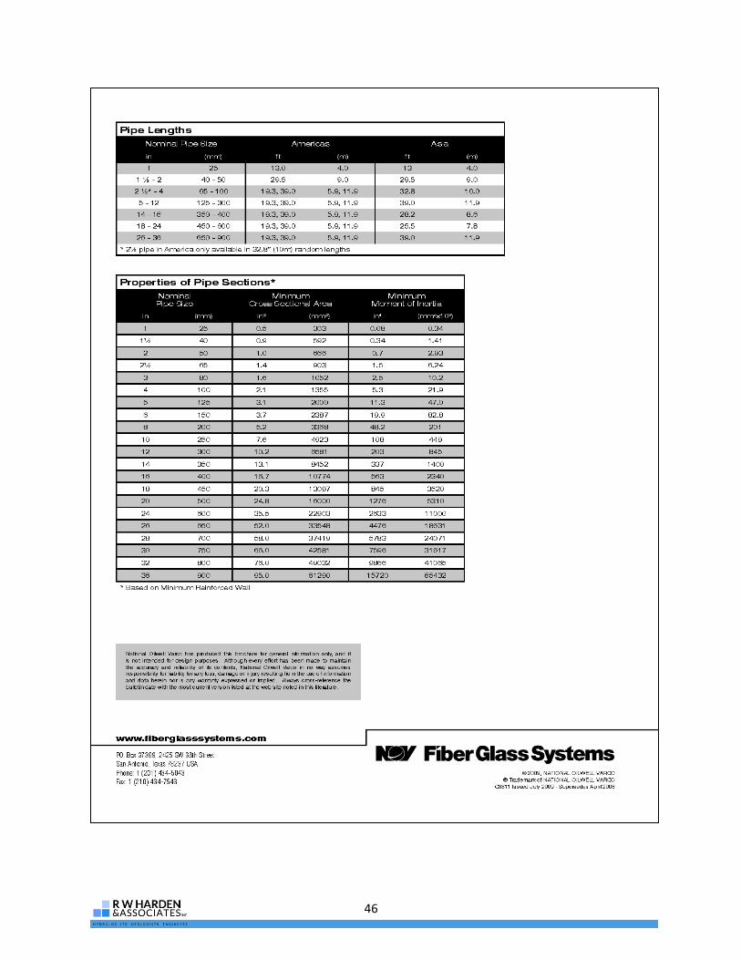
46

47
Appendix B: Applicable Fiberglass Well Casing Regulations in Other States

48
This page left intentionally blank

49
Nebraska
Nebraska Health and Human Services Regulation and Licensure 178 NAC 12 Title 178 –
Water Well Standards.
Chapter 12: Water Well Construction, Pump Installation, and Water Well
Decommissioning Standards
12-003.04 Well Casing: All wells other than test holes and closed loop heat pump wells must be cased.
Well casing must be composed of nontoxic durable material compatible with the water quality
encountered.
12-003.04A Casing Wall Thickness: The wall thickness of water well casing must be sufficient to
withstand the pressures exerted by the surrounding materials, forces imposed on it during installation, and
corrosion by soil and water environments.
12-003.04B Casing Placement: The casing must be centered in the borehole in areas of grout so there is a
minimum 2-inch uniform annular space.
12-003.04C Watertight Casing must be constructed of steel, PVC, fiberglass, or teflon. Plastic watertight
casing must be made of virgin material and must be manufactured expressly for water well casing.
12-004.02C Non-steel watertight casing must be made of virgin material, must be manufactured expressly
for well casing, and must meet the following specific requirements:
(1). Casing strength must be not less than 160 pounds per square inch or Standard Dimension Ratio
(SDR) 26.
(2). Plastic or other non-steel casing must bear the National Sanitation Foundation (NSF) 61 stamp of
approval.
12-004.02D Special Engineered (SE) plastic piping systems must meet the requirements of 178 NAC 12-
004.02C item 2.
Florida
Water Well Permitting and Construction Requirements
62-532.500 Water Well Construction Standards.
(1)(a) Well casing, liner pipe, and well screen shall be new or in like new condition. Such well
casing, liner pipe, or well screen shall not be used unless free of breaks, corrosion and dents, is
straight and true, and not out of round. Welded or seamless black or galvanized steel pipe or
casing, or stainless steel pipe or casing; or approved types of nonmetalic pipe shall be used for
well casing or liner pipe. All well casing shall conform to one of the following standards:
American Society for Testing and Materials (ASTM) A53/A53M-99b, A135-01, A252-98,

50
A589-96, or American Petroleum Institute (API) 5L-2000. Well casing that conforms to any of
the aforementioned ASTM or API standards shall also conform to the American National
Standard for Welded and Seamless Wrought Steel Pipe (ANSI/ASME B36.10M-2000). All well
casing shall be stenciled with the applicable standard, or proper documentation of manufacturer
specifications must be supplied to the permitting authority upon request.
(f) The Department shall approve a well casing or liner pipe not otherwise specified in Rule 62-
532.500(1)(a) through (e), F.A.C., if the applicant makes a showing, certified by a professional
engineer, to justify that such use would provide an equivalent material strength and durability.
The following material has been approved pursuant to this procedure:
DNS Well-Cor, Allied Tube and Conduit, A Division of Grinnel Corporation, 1440 Massaro
Boulevard, Tampa, Florida, 33619.
Nominal Size (in) Outside Diameter (in) Wall Thickness (in)
1.25 1.638 0.085
2 2.360 0.095
4 4.466 0.150
(g) Well casing, liner pipe, and well screens used for potable water well construction or repair
shall conform to Section 6 of NSF International Standard 14-2001, Plastics Piping System
Components and Related Materials, or NSF International Standard 61-2001, Drinking Water
System Components – Health Effects, both of which are adopted and incorporated by reference
herein.
Arkansas
Arkansas Water Well Construction Commission Rules and Regulations
V. Construction
5.4.8 Fiberglass casing. Fiberglass reinforced plastic well casing, tested in accordance with
ASTM D1180 (American Society Testing Materials), may be used where judged desirable by the
contractor and approved by the customer, in consolidated and unconsolidated formations. Each
coupling shall form a watertight seal. Pipe having a minimum bursting pressure of 660 psi may
be used.
6.7 Public and semi-public wells. Wells for public and semi-public water systems shall be
located, designed, and constructed in accordance with the respective regulations of the Arkansas
Department of Health (ADH) and shall have written approval from the ADH prior to the start of

51
construction. If uncertain that a well is public or semi-public, the well contractor shall obtain a
written determination from the ADH prior to construction.
Arkansas State Board of Health
Rules and Regulations Pertaining to Public Supply Systems
VIII.B Well Construction
All public water wells, whether community or non-community, shall be constructed in
accordance with the latest edition of AWWA Standard A100 and approved by the Arkansas
Department of Health. A copy of the well construction log shall be filed with the Arkansas
Department of Health.
1. Casing
Every well must have an outside water tight casing extending below the ground surface to such a
depth as may be necessary, depending upon the character of the underground formations, to
exclude the entrance of undesirable water and sub-surface contamination, as determined by the
Arkansas Department of Health. The outer casing should be seated securely into an impervious
formation whenever possible, otherwise the casing should extend as far as practical below the
water table. The casing, when it extends into a pump room, shall project above the pump room
floor, and safely above maximum flood elevation.

52
This page left intentionally blank

53
Appendix C: GreenThread Pipe Chemical Resistance

54
This page left intentionally blank
55

56

57

58
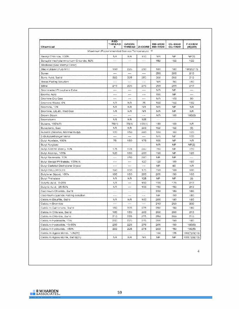
59

60
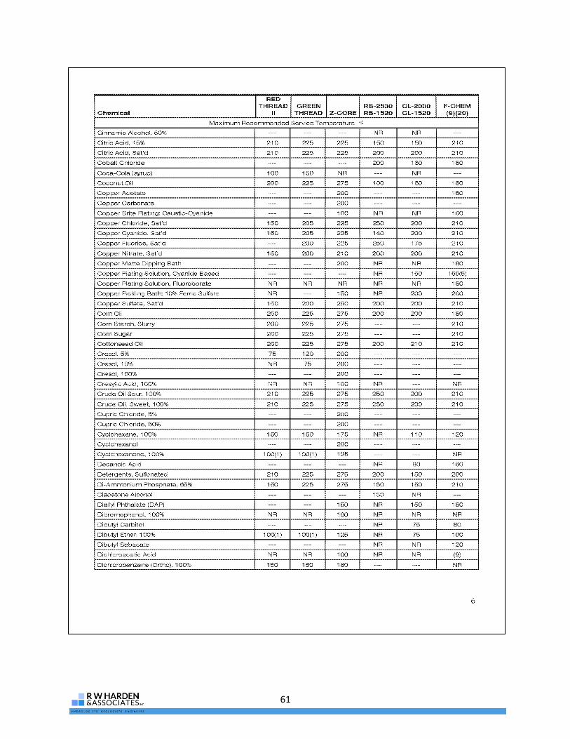
61

62

63

64

65
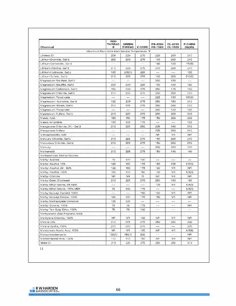
66

67

68
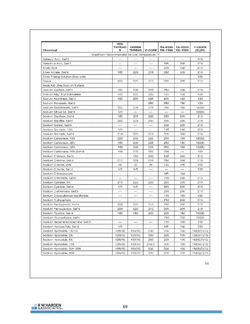
69
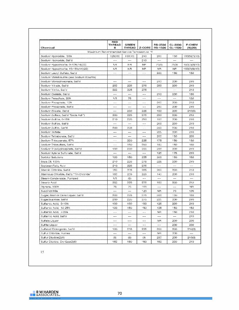
70

71

72
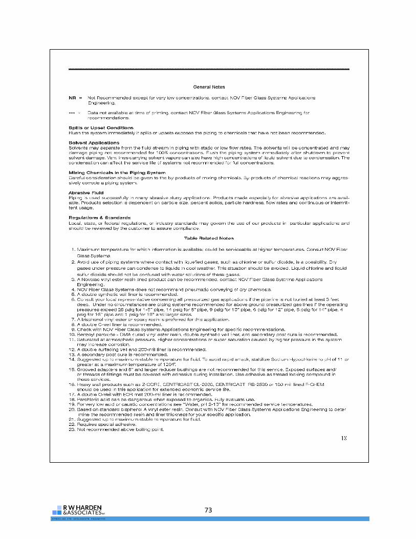
73
74

75
Appendix D: GreenThread Pipe General Specifications

76
This page left intentionally blank

77
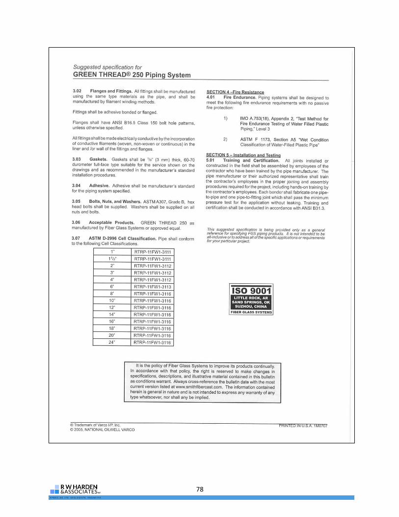
78

79
Appendix E: GreenThread Certifications

80
This page left intentionally blank

81

82

83

84
This page left intentionally blank

85
Appendix F: Fiberglass Well Construction Correspondence

86
This page left intentionally blank
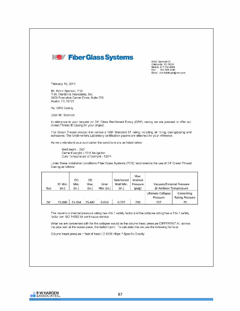
87
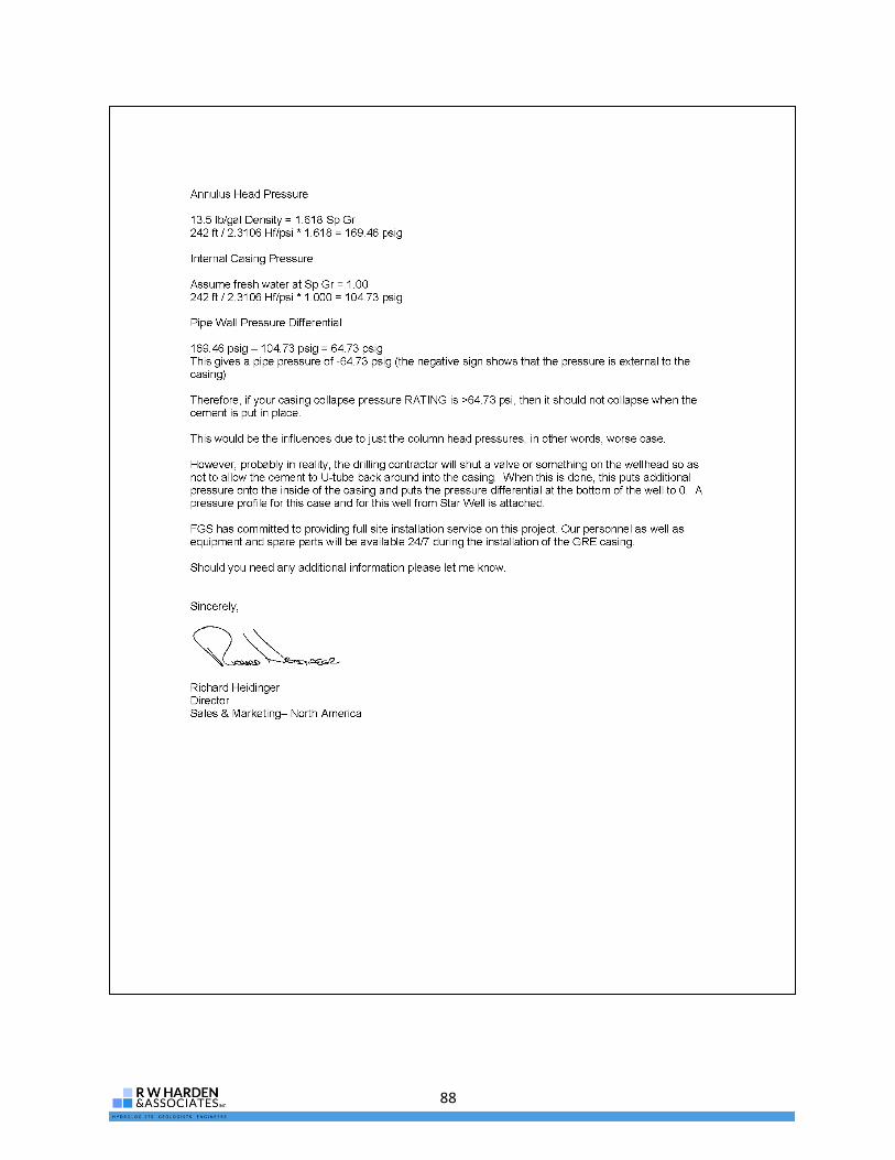
88
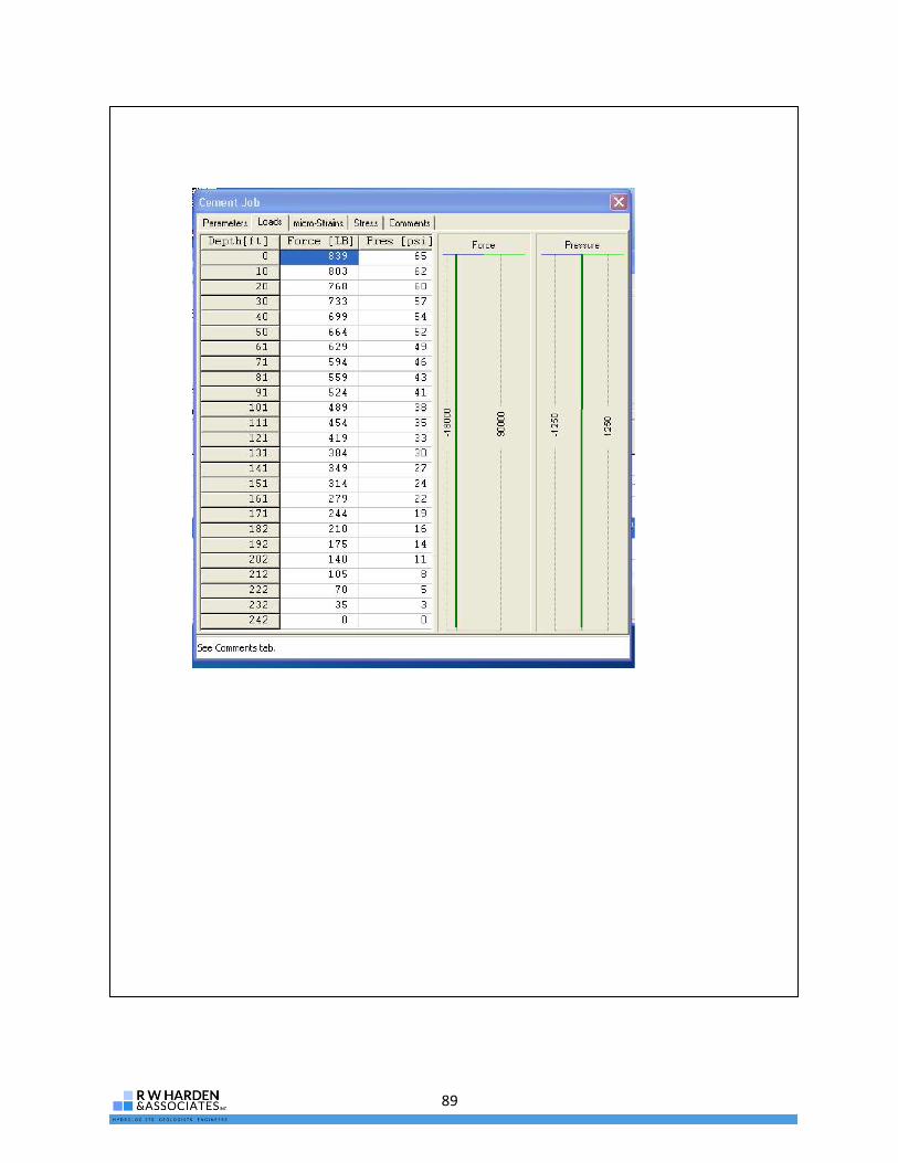
89

90
This page left intentionally blank
91
Appendix G: GreenThread Pipe Coupling System Schematics

92
This page left intentionally blank

93

94
This page left intentionally blank

95
Appendix H: TCEQ Variance Request Correspondence

96
This page left intentionally blank

97

98

99

100

101

102
This page left intentionally blank

103
Appendix I: Test Drilling Report

104
This page left intentionally blank

105
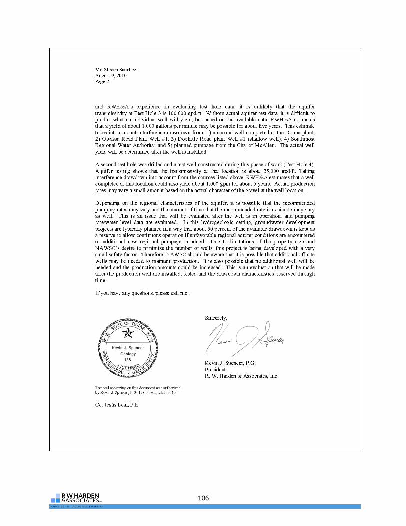
106

107
Addendum: TWDB Comments and Authors’ Responses

108
This page left intentionally blank

109

110

111

112

113
114

115
Attachments

116
This page left intentionally blank

117

118
This page left intentionally blank