guide for installers mettler toledo multirange explosion ... · mettler toledo multirange explosion...
TRANSCRIPT
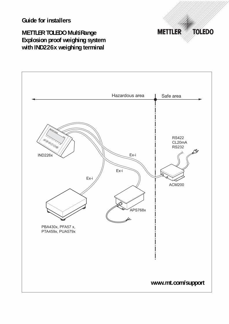
Guide for installers
METTLER TOLEDO MultiRangeExplosion proof weighing systemwith IND226x weighing terminal
RS422CL20mARS232
ACM200
Hazardous area Safe area
www.mt.com/support

Contents
Guide for installers 72203958C 11/12 3
IND226x
Contents Page
1 Safety instructions....................................................................... 4
2 System overview ......................................................................... 62.1 Typical configurations ................................................................... 62.2 Description of components ............................................................ 8
3 Installation.................................................................................. 103.1 Setting up system modules ............................................................ 103.2 Connecting devices ....................................................................... 113.3 Selecting peripheral devices ........................................................... 133.4 Installing the equipotential bonding................................................. 143.5 Connecting power supply .............................................................. 14
4 Optional work.............................................................................. 154.1 Customizing connection cables: Weighing platform / APS768x .......... 154.2 Connection cable extension power supply unit APS500 / APS501 ...... 164.3 Customizing connection cables: Second display /
interface converter ACM200 ........................................................... 184.4 Configuring module ACM200-CL/RS422 ......................................... 19
5 Technical data............................................................................. 205.1 Dimensional drawing .................................................................... 205.2 Technical data of the CL20mA interface of the module
ACM200-CL/RS422 ...................................................................... 21
6 Disposal ..................................................................................... 22
7 Terminal diagram ........................................................................ 24
Safety instructions IND226x
1 Safety instructions
The IND226x weighing terminal is approved for operation in Zone 1 and 21 hazardous areas as well as for Division 1 areas. The interface converter ACM200 may only be installed and operated in the safe area.If the IND226x weighing terminal is used in hazardous areas, special care must be taken. The code of practice is oriented to the "Safe Distribution" concept drawn up by METTLER TOLEDO.
Competence ▲ The weighing system may only be installed, maintained and repaired by authorized METTLER TOLEDO service personnel.
▲ The mains supply may only be installed by a specialist authorised by the owner-operator.
Ex approval ▲ No modifications may be made to the terminal and no repair work may be performed on the modules. Any weighing platform or system modules that are used must comply with the specifications contained in the installation instructions. Non-compliant equipment jeopardizes the intrinsic safety of the system, cancels the "Ex" approval and renders any warranty or product liability claims null and void.
▲ The safety of the weighing system is only guaranteed when the weighing system is operated, installed and maintained in accordance with the respective instructions.
▲ Also comply with the following: – the instructions for the system modules, – the regulations and standards in the respective country,– the statutory requirement for electrical equipment installed in hazardous areas
in the respective country,– all instructions related to safety issued by the owner.
▲ The explosion-protected weighing system must be checked to ensure compliance with the requirements for safety before being put into service for the first time, following any service work and every 3 years, at least.
Operation ▲ Prevent the build-up of static electricity. Always wear suitable working clothes when operating or performing service work in a hazardous area.
▲ Do not use protective coverings for the devices.
▲ Protect the keyboard membrane against ultraviolet radiation.
▲ Avoid damage to the system components.
4 Guide for installers 72203958C 11/12
Safety instructionsIND226x
Installation ▲ Only install or perform maintenance work on the weighing system in the hazardous areas if the following conditions are fulfilled:– if the intrinsically safe characteristic values and zone approval of the individual
components are in accord with one another,– the owner has issued a permit ("spark permit" or "fire permit"), – the area has been rendered safe and the owner's safety co-ordinator has
confirmed 11/12 there is no danger, – the necessary tools and any required protective clothing are provided (danger
of the build-up of static electricity).
▲ The certification papers (certificates, manufacturer’s declarations) must be present.
▲ Lay cabling securely so that it does not move and effectively protect it against damage.
▲ Only route cables into the housing of the system modules via the approved earthing cable glands and ensure proper seating of the seals.
Guide for installers 72203958C 11/12 5
System overview IND226x
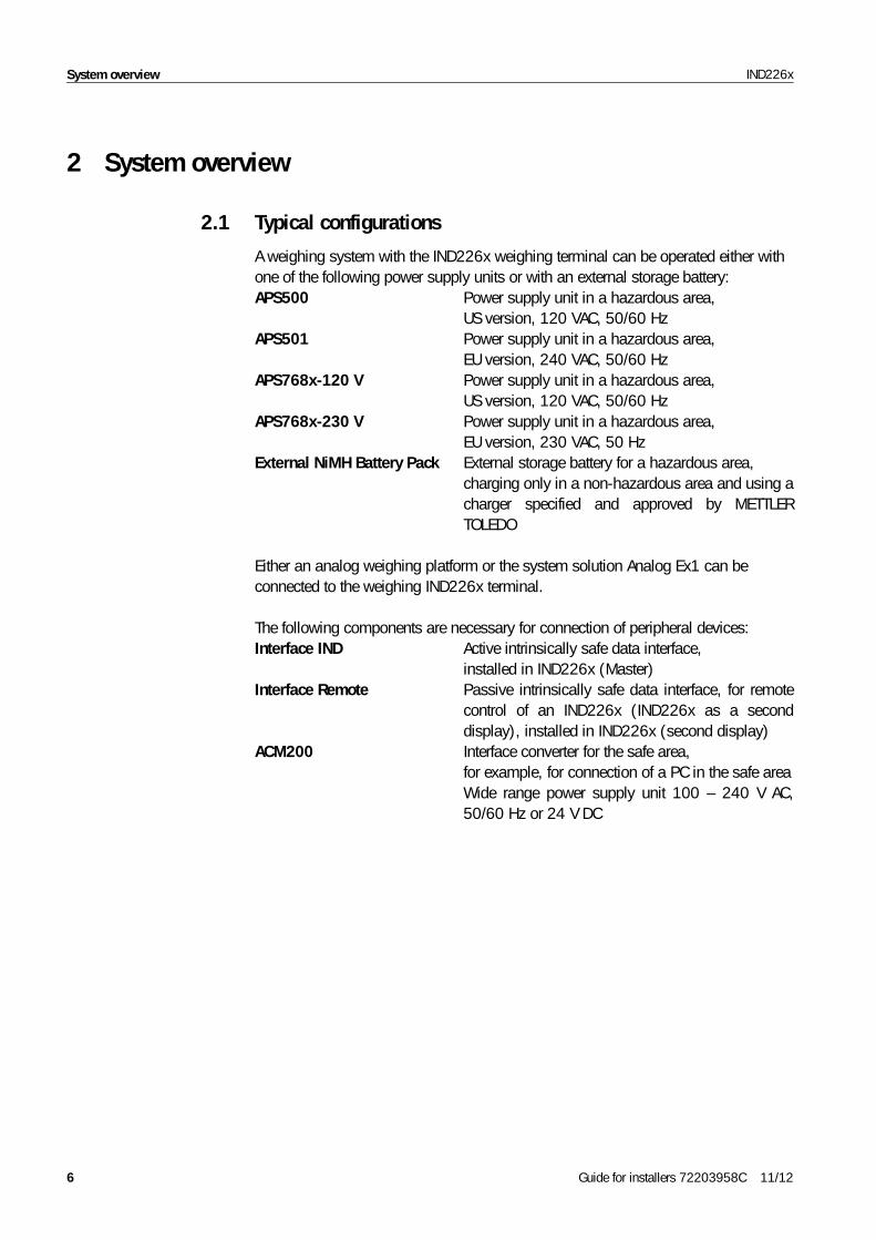
2 System overview
2.1 Typical configurations
A weighing system with the IND226x weighing terminal can be operated either with one of the following power supply units or with an external storage battery:APS500 Power supply unit in a hazardous area,
US version, 120 VAC, 50/60 HzAPS501 Power supply unit in a hazardous area,
EU version, 240 VAC, 50/60 HzAPS768x-120 V Power supply unit in a hazardous area,
US version, 120 VAC, 50/60 HzAPS768x-230 V Power supply unit in a hazardous area,
EU version, 230 VAC, 50 HzExternal NiMH Battery Pack External storage battery for a hazardous area,
charging only in a non-hazardous area and using a charger specified and approved by METTLER TOLEDO
Either an analog weighing platform or the system solution Analog Ex1 can be connected to the weighing IND226x terminal.
The following components are necessary for connection of peripheral devices:Interface IND Active intrinsically safe data interface,
installed in IND226x (Master)Interface Remote Passive intrinsically safe data interface, for remote
control of an IND226x (IND226x as a second display), installed in IND226x (second display)
ACM200 Interface converter for the safe area, for example, for connection of a PC in the safe area Wide range power supply unit 100 – 240 V AC, 50/60 Hz or 24 V DC
6 Guide for installers 72203958C 11/12
System overviewIND226x
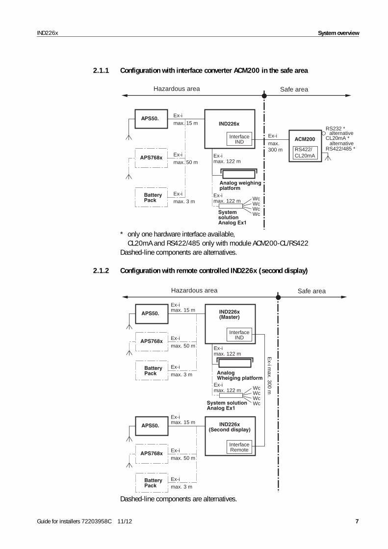
2.1.1 Configuration with interface converter ACM200 in the safe area
IND226xAPS50. Ex-i
max. 15 m
APS768x Ex-i
max. 50 m
BatteryPack
Ex-i
max. 3 m
Analog weighingplatform
Wc
SystemsolutionAnalog Ex1
WcWcWc
Ex-imax. 122 m
Ex-imax. 122 m
Hazardous area Safe area
Ex-i
max. 300 m
InterfaceIND ACM200
RS422/CL20mA
RS232 *
RS422/485 *
alternativeCL20mA *
alternative
* only one hardware interface available, CL20mA and RS422/485 only with module ACM200-CL/RS422
Dashed-line components are alternatives.
2.1.2 Configuration with remote controlled IND226x (second display)
IND226x(Master)
AnalogWheiging platform
Ex-imax. 122 m
InterfaceIND
IND226x(Second display)
APS50.
Ex-imax. 15 m
InterfaceRemote
Ex-i m
ax. 300 m
BatteryPack
Ex-i
max. 3 m
APS768x Ex-i
max. 50 m
Wc
System solutionAnalog Ex1
WcWcWc
Ex-imax. 122 m
APS50.
Ex-imax. 15 m
BatteryPack
Ex-i
max. 3 m
APS768x Ex-i
max. 50 m
Hazardous area Safe area
Dashed-line components are alternatives.
Guide for installers 72203958C 11/12 7
System overview IND226x
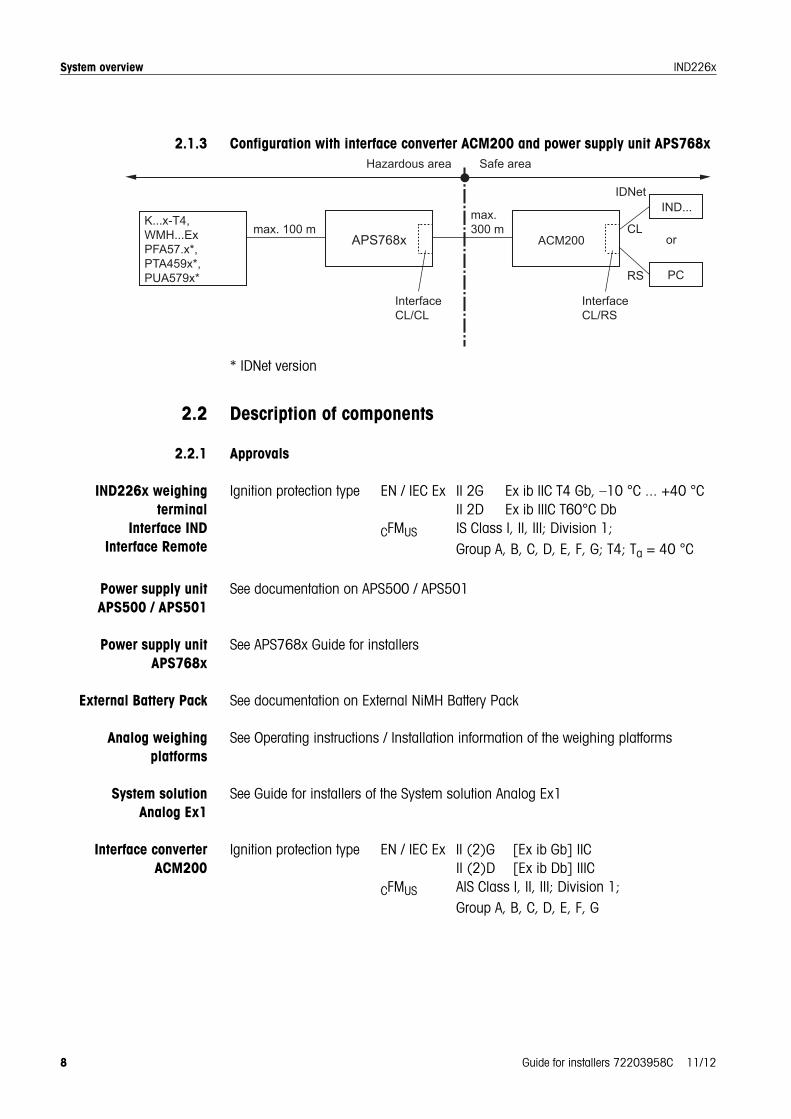
2.1.3 Configuration with interface converter ACM200 and power supply unit APS768x
* IDNet version
2.2 Description of components
2.2.1 Approvals
IND226x weighingterminal
Interface INDInterface Remote
Ignition protection type EN / IEC Ex II 2G Ex ib IIC T4 Gb, –10 °C ... +40 °CII 2D Ex ib IIIC T60°C Db
CFMUS IS Class I, II, III; Division 1; Group A, B, C, D, E, F, G; T4; Ta = 40 °C
Power supply unit APS500 / APS501
See documentation on APS500 / APS501
Power supply unitAPS768x
See APS768x Guide for installers
External Battery Pack See documentation on External NiMH Battery Pack
Analog weighingplatforms
See Operating instructions / Installation information of the weighing platforms
System solutionAnalog Ex1
See Guide for installers of the System solution Analog Ex1
Interface converterACM200
Ignition protection type EN / IEC Ex II (2)G [Ex ib Gb] IIC II (2)D [Ex ib Db] IIIC
CFMUS AIS Class I, II, III; Division 1; Group A, B, C, D, E, F, G
max. 100 mmax.300 m
K...x-T4, WMH...ExPFA57.x*, PTA459x*, PUA579x*
ACM200
InterfaceCL/RS
CL
IDNet
RS
or
IND...
PC
InterfaceCL/CL
8 Guide for installers 72203958C 11/12
System overviewIND226x
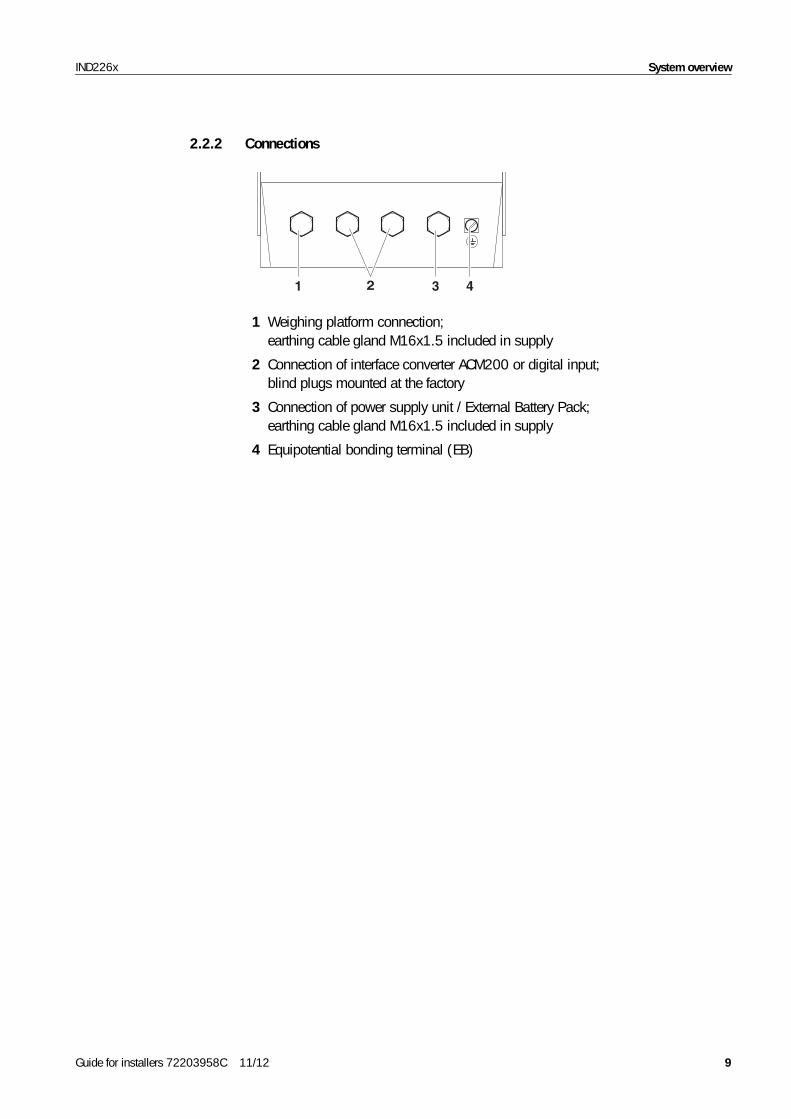
2.2.2 Connections
1 2 3 4
1 Weighing platform connection; earthing cable gland M16x1.5 included in supply
2 Connection of interface converter ACM200 or digital input; blind plugs mounted at the factory
3 Connection of power supply unit / External Battery Pack; earthing cable gland M16x1.5 included in supply
4 Equipotential bonding terminal (EB)
Guide for installers 72203958C 11/12 9
Installation IND226x
3 Installation
EXPLOSION HAZARDThe explosion-protected weighing system may only be installed according to these installation instructions and the terminal diagram 72203677 on Pages 24 to 29.
3.1 Setting up system modules
3.1.1 Setting up the IND226x weighing terminal
➜ Select a suitable installation site.
Bench stand or floor stand mounting
➜ Place weighing terminal onto the bench or floor stand and mount with 4 screws.
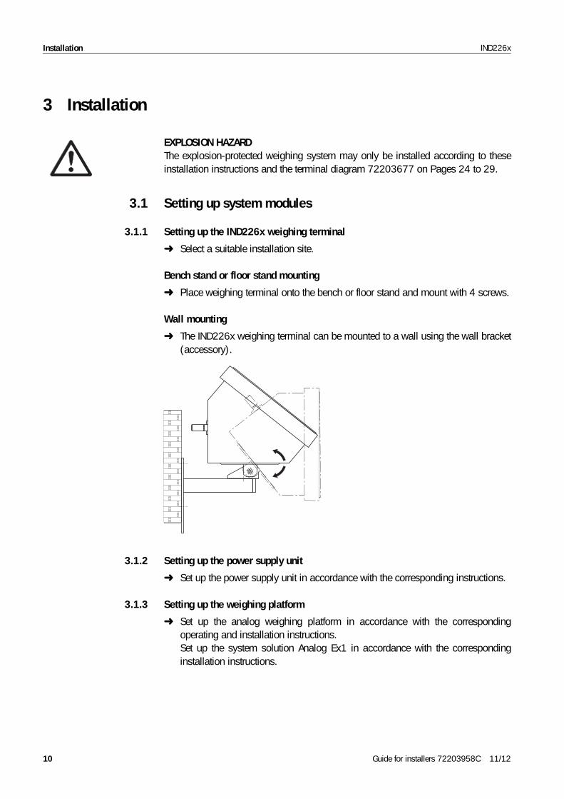
Wall mounting
➜ The IND226x weighing terminal can be mounted to a wall using the wall bracket (accessory).
3.1.2 Setting up the power supply unit
➜ Set up the power supply unit in accordance with the corresponding instructions.
3.1.3 Setting up the weighing platform
➜ Set up the analog weighing platform in accordance with the corresponding operating and installation instructions. Set up the system solution Analog Ex1 in accordance with the corresponding installation instructions.
10 Guide for installers 72203958C 11/12
InstallationIND226x
3.1.4 Setting up the ACM200
➜ Set up the interface converter ACM200 in the safe area. See dimensional drawing on Page 20 for drill hole dimensions for fixed installation.
3.2 Connecting devices
CAUTION
• The clamping section of the earthing cable gland must agree with the outer diameter of the weighing platform cable to be connected.
• Use the supplied flexible tubes to protect the individual wires of the weighing platform cable on the inside of the IND226x.
Connect the devices in the following order:
1. Connect the weighing platform or system solution Analog Ex1 to the weighing terminal IND226x.
2. If present, connect intrinsically safe equipment (e.g. a simple switch / push button) to the intrinsically safe input of the weighing terminal IND226x.
3. Connect the power supply unit (APS500 / APS501, APS768x or External Battery Pack) to the weighing terminal IND226x.
4. Connect the interface converter ACM200, if present, to the weighing terminal IND226x.
5. Install the equipotential bonding, see Section 3.4.
6. Connect power supply, see Section 3.5.
3.2.1 Preparatory workConnection of the devices is generally carried out with the accompanying standard cables. Cables of other lengths can be used instead of the standard cables if they are customized in accordance with Chapter 4. This applies for the following connections
• from the weighing platform or system solution Analog Ex1 to the weighing terminal,
• from the power supply unit APS500 / APS501 or APS768x to the weighing terminal,
• from the interface converter ACM200 to the weighing terminal.
Guide for installers 72203958C 11/12 11
Installation IND226x
3.2.2 General connection procedure
1. Open the device.
2. Pull the customized cable through the earthing cable gland. To do this
– dismantle the earthing cable gland or remove the blind plug,– ensure the exact course of the cable and properly positioned seals,– tighten the earthing cable gland.
3. Connect the cable in the device according to the terminal diagram.
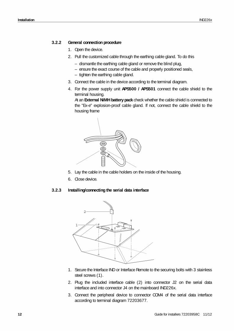
4. For the power supply unit APS500 / APS501 connect the cable shield to the terminal housing. At an External NiMH battery pack check whether the cable shield is connected to the "Ex-e" explosion-proof cable gland. If not, connect the cable shield to the housing frame
5. Lay the cable in the cable holders on the inside of the housing.
6. Close device.
3.2.3 Installing/connecting the serial data interface
2
1
1. Secure the Interface IND or Interface Remote to the securing bolts with 3 stainless steel screws (1).
2. Plug the included interface cable (2) into connector J2 on the serial data interface and into connector J4 on the mainboard IND226x.
3. Connect the peripheral device to connector COM4 of the serial data interface according to terminal diagram 72203677.
12 Guide for installers 72203958C 11/12
InstallationIND226x
3.2.4 Connection of the digital input at the IND226x
CAUTIONDesign, calculation and installation of equipment at the digital input is solely the responsibility of the owner, see section 3.3.
1. Connect only certified devices which are approved for Zone 1/21 or Division 1 hazardous areas. When dimensioning the device to be connected, take the particularly low current/voltage value of the active input of the IND226x into consideration.
2. Check the characteristic values for intrinsic safety in accordance with the conformity certificate of the IND226x and the equipment to be connected according to the conditions in Section 3.3. Document checking of the characteristic values.
3. Customize a cable on the weighing terminal side in accordance with Section 4.3and on the peripheral side according to the device to be connected. Heed the maximum cable length here.
4. Connect the cable on the peripheral device side according to the intended device. Ensure correct polarity here!
3.3 Selecting peripheral devices
CAUTIONRefer to the approval documentation of the peripheral device for all characteristic values of the peripheral device listed in the following.
The following conditions must be fulfilled. See also terminal diagram IND226x:
1. Ui (peripheral device) ≥ U0 (IND226x)
2. Ii (peripheral device) ≥ I0 (IND226x)
3. Pi (peripheral device) ≥ P0 (IND226x)
4. Ci (peripheral device) + Ccable ≤ Co (IND226x)
5. Li (peripheral device) + Lcable ≤ Lo (IND226x)
6. La max (peripheral device) / Ra (peripheral device) < Lcable / Rcable, with Lcable being the length-based inductivity and Rcable the length-specific resistance of the cable to be used.
ATEX Directive for connection to the active inputIn the case of a simple apparatus in accordance with Section 5.7 EN/IEC 60079-1, the external simple apparatus in a hazardous gas environment does not require an identification for use in Zone 1.In a hazardous dust environment, Table 1 of the EN/IEC 61241-11 has to be taken into consideration, for example the relevant regulation has to be applied for the certified output P0 = 1.4 mW.
Guide for installers 72203958C 11/12 13
Installation IND226x
FM Directive for connection to the active inputA simple apparatus is defined in Section 504.2 of the National Electric Code (NFPA 70) as "An electrical component or combination of components of simple construction with well-defined electrical parameters that does not generate more than 1.5 volts, 100 milliamps, and 25 milliwatts, and is compatible with the intrinsic safety of the circuit in which it is used."Section 504.4 of the National Electric Code states that "simple apparatus, as described on the control drawing, shall not be required to be listed".
3.4 Installing the equipotential bonding
Equipotential bonding must be installed by an electrician authorized by the owner. METTLER TOLEDO Service only has a monitoring and consulting function here.
➜ Connect equipotential bonding (EB) of all devices (power supply unit, weighing terminal, interface converter and weighing platform) in accordance with the terminal diagram and the country-specific regulations and standards. In the process it must be ensured that– all device housings are connected to the same potential via the EB terminals,– no circulating current flows via the cable shielding for intrinsically safe circuits,– the neutral point for equipotential bonding is as close to the weighing system
as possible.
3.5 Connecting power supply
EXPLOSION HAZARDThe mains connection of the power supply unit must be made by a professional electrician authorized by the owner and in accordance with the respective terminal diagram, the accompanying installation instructions as well as the country-specific regulations.
14 Guide for installers 72203958C 11/12
Optional workIND226x
4 Optional work
4.1 Customizing connection cables: Weighing platform / APS768x
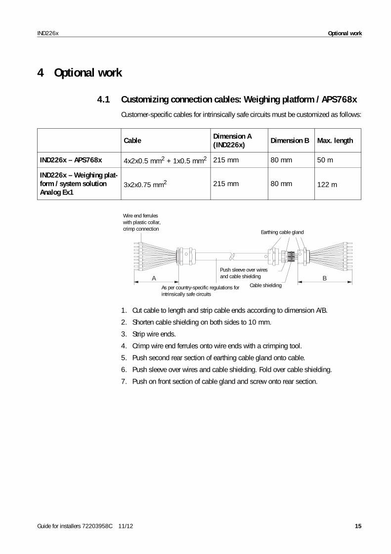
Customer-specific cables for intrinsically safe circuits must be customized as follows:
Cable Dimension A (IND226x) Dimension B Max. length
IND226x – APS768x 4x2x0.5 mm2 + 1x0.5 mm2 215 mm 80 mm 50 m
IND226x – Weighing plat-form / system solution Analog Ex1
3x2x0.75 mm21 215 mm 80 mm 122 m1
A B
Earthing cable gland
Cable shielding
Push sleeve over wires and cable shielding
As per country-specific regulations for intrinsically safe circuits
Wire end ferruleswith plastic collar, crimp connection
1. Cut cable to length and strip cable ends according to dimension A/B.
2. Shorten cable shielding on both sides to 10 mm.
3. Strip wire ends.
4. Crimp wire end ferrules onto wire ends with a crimping tool.
5. Push second rear section of earthing cable gland onto cable.
6. Push sleeve over wires and cable shielding. Fold over cable shielding.
7. Push on front section of cable gland and screw onto rear section.
Guide for installers 72203958C 11/12 15
Optional work IND226x
4.2 Connection cable extension power supply unit APS500 / APS501
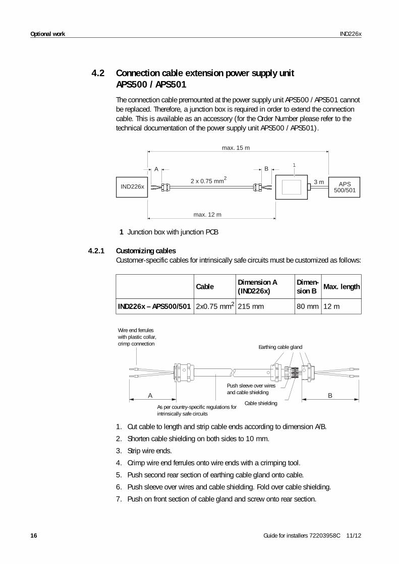
The connection cable premounted at the power supply unit APS500 / APS501 cannot be replaced. Therefore, a junction box is required in order to extend the connection cable. This is available as an accessory (for the Order Number please refer to the technical documentation of the power supply unit APS500 / APS501).
IND226x APS500/501
3 m
max. 12 m
max. 15 m
A B1
2 x 0.75 mm2
1 Junction box with junction PCB
4.2.1 Customizing cablesCustomer-specific cables for intrinsically safe circuits must be customized as follows:
Cable Dimension A (IND226x)
Dimen-sion B Max. length
IND226x – APS500/501 2x0.75 mm2 215 mm 80 mm 12 m
A B
Earthing cable gland
Cable shielding
Push sleeve over wires and cable shielding
As per country-specific regulations for intrinsically safe circuits
Wire end ferruleswith plastic collar, crimp connection
1. Cut cable to length and strip cable ends according to dimension A/B.
2. Shorten cable shielding on both sides to 10 mm.
3. Strip wire ends.
4. Crimp wire end ferrules onto wire ends with a crimping tool.
5. Push second rear section of earthing cable gland onto cable.
6. Push sleeve over wires and cable shielding. Fold over cable shielding.
7. Push on front section of cable gland and screw onto rear section.
16 Guide for installers 72203958C 11/12
Optional workIND226x
4.2.2 Connecting
APS500 / APS501 – junction box
1. Introduce the premounted Ex-i connection cable via a suitable and approved earthing cable gland into the junction box.
2. Ensure correct positioning of the seal and tighten the earthing cable gland.
3. Connect the conductors of the premounted connection cable to the junction PCB of the junction box. Place cable shielding on the junction box housing. See the documentation on APS500 / APS501 for the connection assignment.
Junction box – IND226x 1. Introduce the customized customer-specific Ex-i connection cable via the supplied earthing cable gland into the junction box.
2. Ensure correct positioning of the seal and tighten the cable gland.
3. Connect the conductors of the customized connection cable to the junction PCB of the junction box. See the documentation on APS500 / APS501 for the connection assignment.
4. Introduce the customized customer-specific cable into the IND226x and connect it in accordance with the terminal diagram 72203677 found on page 24.
Guide for installers 72203958C 11/12 17
Optional work IND226x
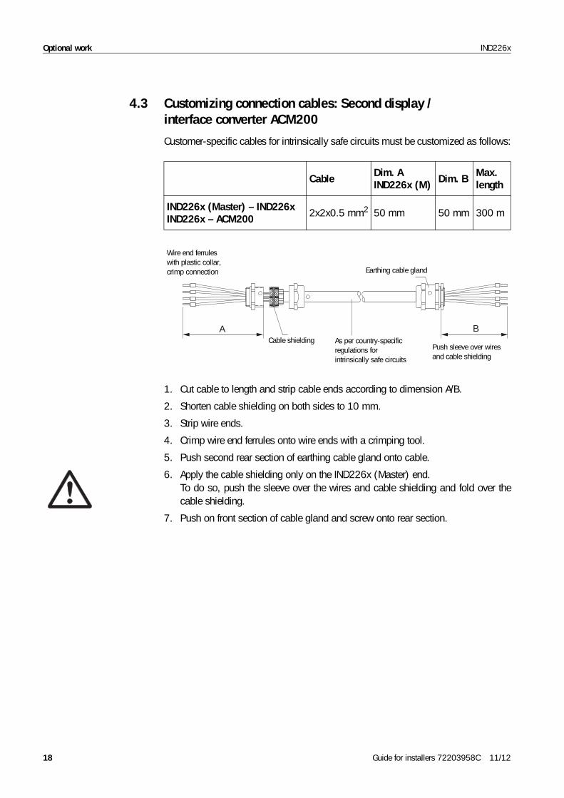
4.3 Customizing connection cables: Second display / interface converter ACM200
Customer-specific cables for intrinsically safe circuits must be customized as follows:
Cable Dim. A IND226x (M) Dim. B Max.
length
IND226x (Master) – IND226xIND226x – ACM200 2x2x0.5 mm2 50 mm 50 mm 300 m
BA
Earthing cable gland
Cable shieldingPush sleeve over wires and cable shielding
As per country-specific regulations for intrinsically safe circuits
Wire end ferruleswith plastic collar, crimp connection
1. Cut cable to length and strip cable ends according to dimension A/B.
2. Shorten cable shielding on both sides to 10 mm.
3. Strip wire ends.
4. Crimp wire end ferrules onto wire ends with a crimping tool.
5. Push second rear section of earthing cable gland onto cable.
6. Apply the cable shielding only on the IND226x (Master) end. To do so, push the sleeve over the wires and cable shielding and fold over the cable shielding.
7. Push on front section of cable gland and screw onto rear section.
18 Guide for installers 72203958C 11/12
Optional workIND226x
4.4 Configuring module ACM200-CL/RS422
4.4.1 Opening the housing
1. Pull the power plug.
2. Open the housing cover of the ACM200.
4.4.2 Setting the jumpers
➜ Plug in the jumpers W1 to W5 as per the table below.
Jumper Meaning Factory setting Note
W2 CL20mA interface Plugged inThe transmission and reception loop operating mode can also be selected, see 4.4.3
W3 RS422 interface – A matching resistor W1 can also be setW4 RS485 interface –
W1 Matching resistorOpen, no matching resistor
Only for RS422/RS485, the matching resistor is required only on the last component of a field bus
W5 Power supply "12 V" position
With the used wide-range power supply unit, it is necessary to insert the jumper in the "12 V" position
4.4.3 Selecting the CL interface operating mode for the module ACM200-CL/RS422The CL interface of the optional module ACM200-CL/RS422 can be operated with either an active or passive transmission and reception loop.Factory setting: Passive transmission and reception loop
1. Pull the power plug.
2. Open the housing cover of the ACM200.
3.
ON DIP
K11 2 3 4 5 6
Set the desired operating mode with the dip switch K1 on the module ACM200-CL/RS422.
Operating mode K1 K2 K3 K4 K5 K6
TXD passive, RXD passive (factory setting)
on on off off off off
TXD active, RXD active off off on on on on
TXD passive, RXD active off on on on off off
TXD active, RXD passive on off off off on on
4.4.4 Closing the housing
➜ Close the housing cover. Ensure correct position of the seal when doing so.
Guide for installers 72203958C 11/12 19
Technical data IND226x
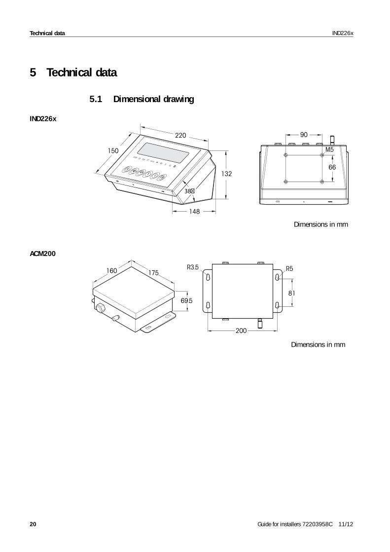
5 Technical data
5.1 Dimensional drawing
90
66132
148
150
220
M5Under O K O ver PT
Ne t lb k g
MinW eigh
Dimensions in mm
IND226x
81
R5
200
175160
69.5
R3.5
Dimensions in mm
ACM200
20 Guide for installers 72203958C 11/12
Technical dataIND226x
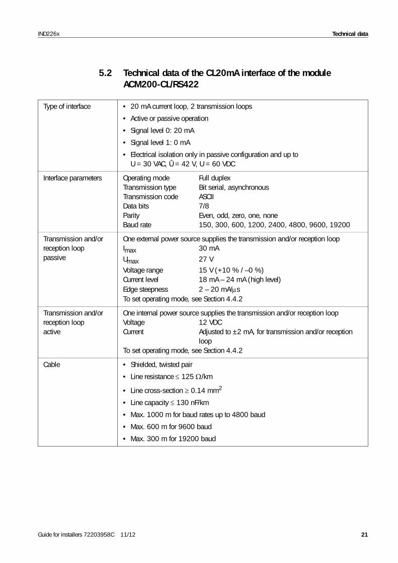
5.2 Technical data of the CL20mA interface of the module ACM200-CL/RS422
Type of interface • 20 mA current loop, 2 transmission loops
• Active or passive operation
• Signal level 0: 20 mA
• Signal level 1: 0 mA
• Electrical isolation only in passive configuration and up to U = 30 VAC, Û = 42 V, U = 60 VDC
Interface parameters Operating mode Full duplexTransmission type Bit serial, asynchronousTransmission code ASCIIData bits 7/8Parity Even, odd, zero, one, noneBaud rate 150, 300, 600, 1200, 2400, 4800, 9600, 19200
Transmission and/or reception loop passive
One external power source supplies the transmission and/or reception loopImax 30 mA
Umax 27 V
Voltage range 15 V (+10 % / –0 %)Current level 18 mA – 24 mA (high level)Edge steepness 2 – 20 mA/μsTo set operating mode, see Section 4.4.2
Transmission and/or reception loop active
One internal power source supplies the transmission and/or reception loopVoltage 12 VDCCurrent Adjusted to ±2 mA, for transmission and/or reception
loopTo set operating mode, see Section 4.4.2
Cable • Shielded, twisted pair
• Line resistance ≤ 125 Ω/km
• Line cross-section ≥ 0.14 mm2
• Line capacity ≤ 130 nF/km
• Max. 1000 m for baud rates up to 4800 baud
• Max. 600 m for 9600 baud
• Max. 300 m for 19200 baud
Guide for installers 72203958C 11/12 21
Disposal IND226x
6 Disposal
In conformance with the European Directive 2002/96/EC on Waste Electrical and Electronic Equipment (WEEE), this device may not be disposed of in domestic waste.This also applies to countries outside the EU as per their specific regulations.
➜ Please dispose of this product in accordance with local regulations at the collecting point specified for electrical and electronic equipment.
If you have any questions, please contact the responsible authority or the distributor from which you purchased this device. Should this device be passed on to other parties (for private or professional use), the content of this regulation must also be related.Thank you for your contribution to environmental protection.
22 Guide for installers 72203958C 11/12

DisposalIND226x
Guide for installers 72203958C 11/12 23
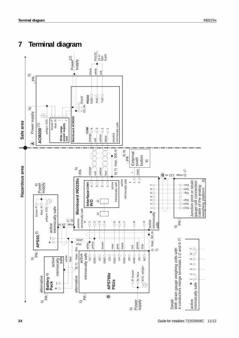
Terminal diagram IND226x
7bl
ue: N
brow
n: P
yel/g
rn: E
/G
Haz
ard
ou
s ar
eaS
afe
area
activ
ein
trin
sica
lly
safe
3U
2
4br
own
U3
5ro
se
6gr
ey
7bl
ack
8re
d
gree
n
9bl
ue
2ye
llow
GN
D
1w
hite
U1
P
GN
D
GN
D
GN
D
GN
DU4
U5
U6
NC
1) m
ax. 5
0 m
5)P
A
alte
rnat
ive
Bat
tery
Pac
k
alte
rnat
ive
blue
whi
te
AP
S50
. activ
ein
trin
sica
lly s
afe
brow
n: P
blue
: N
yel/g
rn: E
/G
Pow
ersu
pply6)
P. b
row
n
N. b
lue
E/G
. yel
/grn
Pow
ersu
pply
6)
pass
ive
intr
insi
cally
saf
e
Mai
nb
oar
d IN
D22
6x5)
PA
max. 15 m3) 7)
3)
7)
max
. 3m
max. 122 m 2)7)
12
34
56
7B
5)P
A
5)P
A
Exc+
Sen+Sig+
Sig–Sen–Exc–
5)P
A
1 2I+
GN
D
7)
8)
5) 9
)P
A
activ
ein
trin
sica
lly
safe
Ext
erna
lpu
shbu
tton
8)
8)
3
Inte
rfac
eIN
D
J4J2
4
activ
ein
trin
sica
lly s
afe
2 1
CO
M4
34 2 1
oran
ge
red
yello
w
bue
4) 7
) m
ax. 3
00 m
pass
ive
intr
insi
cally
saf
e
5)
11)
PA
++
oran
ge
red
yello
w
bblu
e
Mai
nb
oar
d A
CM
200
CO
M
RxD
GN
D
TxD
RS
232
DC
INS
hiel
d
blac
k
whi
te
red
+–
AC
M20
0
+–
activ
ein
trin
sica
lly s
afe
12
34
56
7B
A
B
AP
S76
8xP
SU
xB
RS
232
10 m
9pin
Sub
D
6)P
ower
sup
ply
12)
Pow
ersu
pply
activ
ein
trin
sica
lly s
afe
activ
ein
trin
sica
lly s
afe
blue
white
Junc
tion
prin
t or
stra
inga
uge
cell
conn
ectio
nca
ble
of th
e an
alog
wei
ghin
g pl
atfo
rm8)
Det
ail:
With
str
ain
gaug
e w
eigh
ing
cells
with
4 co
nduc
tors
mer
ge te
rmin
als
1-2
and
6-7!
Wid
e ra
ng
ep
ow
er s
up
ply
un
it
––
Terminal diagram
24 Guide for installers 72203958C 11/12
IND226x – Intrinsically safe entity parameters
Scale interface U0 (Voc) I0 (Isc) P0 C0 (Ca) L0 (La)
CENELEC approval CFMUS approval
Cables conforming to EN50039 and EN60079-14 For installation please refer to ANSI/ISA RP 12.06.01, "Installa-rinsically safe devices in Class I hazardous areas"per country-specific regulations for intrinsically safe
1 x 0.02 in2) shielded and twisted pairwisted pairair cable shield only applied to IND226x end
ction of the equipotential bonding (EB) as per FPA 70, Article 504 and ANSI/IA RP 12.06.01 or ian Electrical Code C22.2. It must be ensured that the
ngs of all devices are connected to the same potential e EB terminals. No circulating current may flow via the ing of the intrinsically safe cables.
ations;
protect it against damage.
ng conditions:
Pi ≥ Po
cordance with NEC (NFPA 70),
m = 250 V rms or DC.
ross section: min. 0.2 mm2, max. 0.8 mm2
APS768x, see terminal diagram 22006397
ice variant ACM200-DC
F)
me Scale Designation
hultz
Terminal diagram IND226x
hultz
Code
72203677
Terminal diagram
Guide for installers 72203958C 11/12
25
IND
226x a
ACM200 – Intrinsically safe entity parameters
Weighing platform characteristicsMeasuring cells max. 4Weighing platform impedance ≥ 87 Ω Nominal characteristic load cell 2 mV/V or 3 mV/V
Terminals B 1–7 5.88 V 156 mA 0.92 W 200 nF 0.3 mH
Digital input (active) U0 (Voc) I0 (Isc) P0 C0 (Ca) L0 (La)
Terminals I 1–2 5.4 V 1 mA 1.4 mW 100 nF 0.1 mH
Power supply Ui Ii Pi Ci Li
Terminals P 1–9 13 V3.16 A 12 W
0 nF 0 mH limited internally
Interface IND U0 (Voc) I0 (Isc) P0 C0 (Ca) L0 (La)
COM4, Terminals 1–4 5.88 V 144 mA 212 mW 600 nF 0.4 mH
Interface Remote Ui Ii Pi Ci Li
COM4, Terminals 1–4 10 V 300 mA 500 mW 120 nF 0 mH
Passive interface Ui Ii Pi Ci Li
COM, Terminals 1–4 10 V 300 mA 500 mW 120 nF 0 mH
Color codes RWMxPFA579x
PFA575xPFA459xPUA579x
DB...sTxDCS...sTx PBA430x
Exc+ gray gray blue green
Sen+ yellow yellow green blue
Sig+ white white white white
Sig– brown brown red red
Sen– green green gray brown
Exc– pink pink black black
for intrinsically safe circuits tion of intCable as circuits
• Cable inlet via earthing cable gland• Cable as per installation instructions ME-72203959
1) Cable 4 x 2 x 0.5 mm2 + 1 x 0.5 mm2 (4 x 2 x 0.02 in2 +2) Cable 3 x 2 x 0.75 mm2 (3 x 2 x 0.03 in2) shielded and t3) Cable 2 x 0.75 mm2 (2 x 0.03 in2) shielded and twisted p4) Cable 2 x 2 x 0.5 mm2 (2 x 2 x 0.02 in2) twisted pair and
5) Connection of equipotential bonding (EB) as per country-specific regulations. It must be ensured that the housings of all devices are connected to the same potential via the EB terminals. No circulating current may flow via the shielding of the intrinsically safe cables.
5) ConneANSI/NCanadhousivia thshield
6) Mains connection in accordance with country-specific regulfor supply voltage and frequency refer to rating plate
7) Lay cabling securely so that it does not move and effectively
8) ATEX- and FM-approved devices in accordance with followi
Ui ≥ Uo (Voc) Ii ≥ Io (Isc)Ci + Ccable < Co (Ca) Li + Lcable < Lo (La) Active input: Connection of simple electrical apparatus in acSections 504.2 and 504.4
9) For connecting devices with a maximum effective value of U
10)Use only shielded cable. Max. cable length 304 m. Cable c
11)Can also be used in conjunction with the power supply unit
12)A power supply with 24 V DC is possible in the case of dev
Ambient temperature range: –10 °C to +40 °C (14 °F to 104 °
C 11/12 Schultz
B 11/03 Schultz
A 09/07 Schultz Date Na
Edi-tion
Change Date NameProc. by 05/07 Sc
Checked 05/07 Sc
Replacement for:/
Sheet 1/3
Mettler-Toledo (Changzhou) Measurement Technology Ltd.
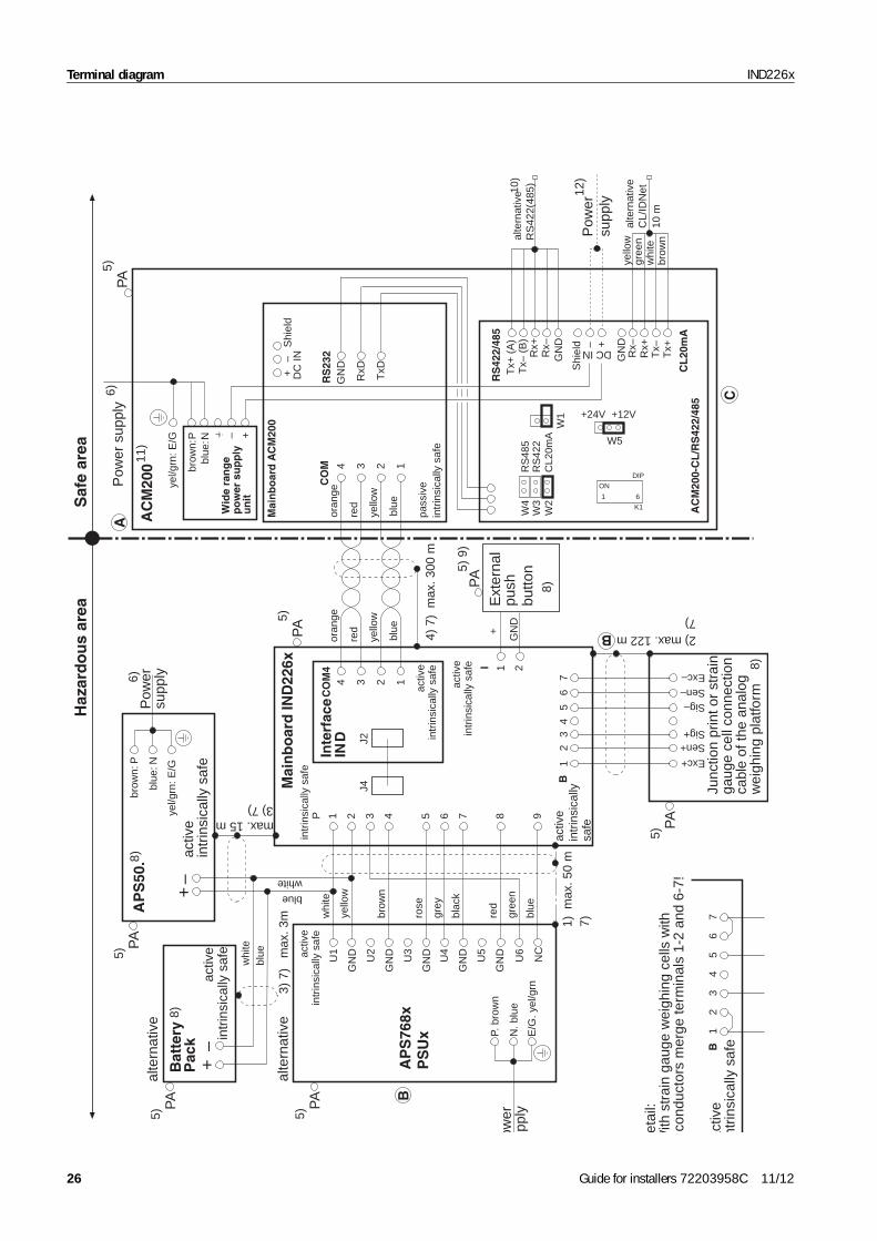
Terminal diagram IND226x
DC
INS
hiel
d+
–
blue
: Nbr
own:
P
yel/g
rn: E
/G
Haz
ard
ou
s ar
eaS
afe
area
activ
ein
trin
sica
lly
safe
3U
2
4br
own
U3
5ro
se
6gr
ey
7bl
ack
8re
d
gree
n
9bl
ue
2ye
llow
GN
D
1w
hite
U1
P
GN
D
GN
D
GN
D
GN
DU4
U5
U6
NC
1) m
ax. 5
0 m
5)P
A
alte
rnat
ive
Bat
tery
Pac
k
alte
rnat
ive
blue
white
blue
whi
te
AP
S50
. activ
ein
trin
sica
lly s
afe
brow
n: P
blue
: N
yel/g
rn: E
/G
Pow
ersu
pply6)
P. b
row
n
N. b
lue
E/G
. yel
/grn
ower
pply
intr
insi
cally
saf
e
Mai
nb
oar
d IN
D22
6x5)
PA
8)
max. 15 m3) 7)
3)
7)
max
. 3m
max. 122 m 2)7)
12
34
56
7B
5)P
A
5)P
A
Exc+
Sen+Sig+
Sig–Sen–Exc–
5)P
A
1 2I+
GN
D
7)
8)
5) 9
)P
A
activ
ein
trin
sica
lly s
afe
Ext
erna
lpu
sh
butto
n
8)
8)
3
Inte
rfac
eIN
D
J4J2
4
activ
ein
trin
sica
lly s
afe
2 1
CO
M4
34 2 1
oran
ge
red
yello
w
blue
4) 7
) m
ax. 3
00 m
pass
ive
intr
insi
cally
saf
e
5)
11)
10)
12)
PA
++
oran
ge
yello
wgr
een
whi
tebr
own
red
yello
w
blue
Mai
nb
oar
d A
RS
422/
485
CM
200
CO
M
RxD
GN
D
TxD
GN
D
RS
232
CL
20m
A
+–W
ide
ran
ge
po
wer
su
pp
lyu
nit
AC
M20
0
W4
W3
W2
W1
RS
485
RS
422
CL2
0mA
ON
K1
DIP
1 6
activ
ent
rinsi
cally
saf
e1
23
45
67
B
A
B
AP
S76
8xP
SU
xB
C
+24V +12V
Tx+
(A
)al
tern
ativ
eR
S42
2(48
5)
Pow
ersu
pply
6)P
ower
sup
ply
alte
rnat
ive
CL/
IDN
et10
m
Tx–
(B
)R
x+R
x–
Rx–
Rx+
Tx–
Tx+
GN
D
W5
Shi
eld DC IN– +
AC
M20
0-C
L/R
S42
2/48
5
activ
ein
trin
sica
lly s
afe
activ
ein
trin
sica
lly s
afe
etai
l:W
ith s
trai
n ga
uge
wei
ghin
g ce
lls w
ithco
nduc
tors
mer
ge te
rmin
als
1-2
and
6-7!
Junc
tion
prin
t or
stra
inga
uge
cell
conn
ectio
nca
ble
of th
e an
alog
wei
ghin
g pl
atfo
rm
––
26 Guide for installers 72203958C 11/12

IND226x – Intrinsically safe entity parameters
Scale interface U0 (Voc) I0 (Isc) P0 C0 (Ca) L0 (La)
CENELEC approval CFMUS approval
Cables conforming to EN50039 and EN60079-14 For installation please refer to ANSI/ISA RP 12.06.01, "Installa-rinsically safe devices in Class I hazardous areas"per country-specific regulations for intrinsically safe
1 x 0.02 in2) shielded and twisted pairwisted pairair cable shield only applied to IND226x end
ction of the equipotential bonding (EB) as per FPA 70, Article 504 and ANSI/IA RP 12.06.01 or ian Electrical Code C22.2. It must be ensured that the
ngs of all devices are connected to the same potential e EB terminals. No circulating current may flow via the ing of the intrinsically safe cables.
ations;
protect it against damage.
ng conditions:
Pi ≥ Po
cordance with NEC (NFPA 70),
m = 250 V rms or DC.
ross section: min. 0.2 mm2, max. 0.8 mm2
APS768x, see terminal diagram 22006397
ice variant ACM200-DC
F)
me Scale Designation
hultz
Terminal diagram IND226x
hultz
Code
72203677
Terminal diagram
Guide for installers 72203958C 11/12
27
IND
226x a
ACM200 – Intrinsically safe entity parameters
Weighing platform characteristicsMeasuring cells max. 4Weighing platform impedance ≥ 87 Ω Nominal characteristic load cell 2 mV/V or 3 mV/V
Terminals B 1–7 5.88 V 156 mA 0.92 W 200 nF 0.3 mH
Digital input (active) U0 (Voc) I0 (Isc) P0 C0 (Ca) L0 (La)
Terminals I 1–2 5.4 V 1 mA 1.4 mW 100 nF 0.1 mH
Power supply Ui Ii Pi Ci Li
Terminals P 1–9 13 V3.16 A 12 W
0 nF 0 mH limited internally
Interface IND U0 (Voc) I0 (Isc) P0 C0 (Ca) L0 (La)
COM4, Terminals 1–4 5.88 V 144 mA 212 mW 600 nF 0.4 mH
Interface Remote Ui Ii Pi Ci Li
COM4, Terminals 1–4 10 V 300 mA 500 mW 120 nF 0 mH
Passive interface Ui Ii Pi Ci Li
COM, Terminals 1–4 10 V 300 mA 500 mW 120 nF 0 mH
Color codes RWMxPFA579x
PFA575xPFA459xPUA579x
DB...sTxDCS...sTx PBA430x
Exc+ gray gray blue green
Sen+ yellow yellow green blue
Sig+ white white white white
Sig– brown brown red red
Sen– green green gray brown
Exc– pink pink black black
for intrinsically safe circuits tion of intCable as circuits
• Cable inlet via earthing cable gland• Cable as per installation instructions ME-72203959
1) Cable 4 x 2 x 0.5 mm2 + 1 x 0.5 mm2 (4 x 2 x 0.02 in2 +2) Cable 3 x 2 x 0.75 mm2 (3 x 2 x 0.03 in2) shielded and t3) Cable 2 x 0.75 mm2 (2 x 0.03 in2) shielded and twisted p4) Cable 2 x 2 x 0.5 mm2 (2 x 2 x 0.02 in2) twisted pair and
5) Connection of equipotential bonding (EB) as per country-specific regulations. It must be ensured that the housings of all devices are connected to the same potential via the EB terminals. No circulating current may flow via the shielding of the intrinsically safe cables.
5) ConneANSI/NCanadhousivia thshield
6) Mains connection in accordance with country-specific regulfor supply voltage and frequency refer to rating plate
7) Lay cabling securely so that it does not move and effectively
8) ATEX- and FM-approved devices in accordance with followi
Ui ≥ Uo (Voc) Ii ≥ Io (Isc)Ci + Ccable < Co (Ca) Li + Lcable < Lo (La) Active input: Connection of simple electrical apparatus in acSections 504.2 and 504.4
9) For connecting devices with a maximum effective value of U
10)Use only shielded cable. Max. cable length 304 m. Cable c
11)Can also be used in conjunction with the power supply unit
12)A power supply with 24 V DC is possible in the case of dev
Ambient temperature range: –10 °C to +40 °C (14 °F to 104 °
C 11/12 Schultz
B 11/03 Schultz
A 09/07 Schultz Date Na
Edi-tion
Change Date NameProc. by 05/07 Sc
Checked 05/07 Sc
Replacement for:/
Sheet 2/3
Mettler-Toledo (Changzhou) Measurement Technology Ltd.
gaug
e ce
ll co
nnec
tion
cabl
e of
the
anlo
gw
eigh
ing
plat
form
8)
Terminal diagram IND226x
Haz
ardo
us a
rea
Saf
e ar
ea
activ
ein
trin
sica
llysa
fe3U
2
4br
own
U3
5pi
nk
6gr
ay
7bl
ack
8re
d
gree
n
9bl
ue
2ye
llow
GN
D
1w
hite
U1
P
GN
D
GN
D
GN
D
GN
DU4
U5
U6
NC
1) m
ax. 5
0 m
5)E
B
alte
rnat
ive
AP
S76
8xP
SU
x
Bat
tery
Pac
k
alte
rnat
ive
blue
white
blue
whi
te
AP
S50
.br
own:
P
blue
: N
ye/g
reen
: E/G
Pow
ersu
pply6)
P. b
row
n
N. b
lue
E/G
. ye/
gree
n
Pow
ersu
pply
6)
pass
ive
intr.
saf
eM
ainb
oard
IND
226x
5)E
B
Junc
tion
prin
t or
stra
inactiv
ein
trin
sica
lly s
afe
max. 15 m3) 7)
3)
7)
max
. 3 m
max. 122 m 2)7)
12
34
56
7B
+
5)E
B
5)E
B
Exc+
Sen+
Sig+
Sig
Sen
Exc
5)E
B
1 2I
7)
activ
ein
trin
sica
lly s
afe
activ
ein
trin
sica
lly s
afe
8)
8)
3
Inte
rfac
eIN
D
J4J2
4
activ
ein
trin
sica
lly s
afe2 1
CO
M4
oran
ge
red
yello
w
blue
+
4) max
. 300
m
activ
ein
trin
sica
lly s
afe
B
B
a
28 Guide for installers 72203958C 11/12
Terminal diagramIND226x
IND2
26x
Repl
acem
ent f
or:
/Sh
eet 3
/3
Met
tler-
Tole
do (
Chan
gzho
u) M
easu
rem
ent T
echn
olog
y Lt
d.Co
de
722
0367
7
a
3U
2
4br
own
U3
5pi
nk
6gr
ay
7bl
ack
8re
d
gree
n
9bl
ue
2ye
lllow
GN
D
1w
hite
U1
P
GN
D
GN
D
GN
D
GN
DU4
U5
U6
NC
1) m
ax. 5
0 m
5)E
B
alte
rnat
ive
AP
S76
8x
Bat
tery
Pac
k
alte
rnat
ive
blue
white
blue
whi
te
AP
S50
.
activ
ein
trin
sica
lly s
afe
brow
n: P
blue
: N
ye/g
reen
: E/G
Pow
ersu
pply6)
P. b
row
n
N. b
lue
E/G
. ye/
gree
n
Pow
ersu
pply
6)
pass
ive
intr.
saf
eM
ain
bo
ard
IND
226x
5)E
B
max. 15 m3) 7)
3)
7)
max
. 3 m
12
34
56
7B
+
5)E
B
5)E
B
1 2I
7)
activ
ein
trin
sica
lly s
afe
activ
ein
trin
sica
lly s
afe
8)
8)
3
Inte
rfac
eR
emo
te
J4J2
4
pass
ive
intr
insi
cally
saf
e
2 1
CO
M4
oran
ge
red
yello
w
blue
+
B
C11
/12
Schu
ltz
B11
/03
Schu
ltz
A09
/07
Schu
ltzD
ate
Nam
eSc
ale
Des
igna
tion
Edi-
tion
Chan
geD
ate
Nam
ePr
oc. b
y05
/07
Schu
ltz
Term
inal
dia
gram
Ch
ecke
d05
/07
Schu
ltz
a
Guide for installers 72203958C 11/12 29
Congratulations on choosing the quality and precision of METTLER TOLEDO. Proper use according to these instruc-tions and regular calibration and maintenance by our factory-trained service team ensure dependable and accurate operation, protecting your investment. Contact us about a ServiceXXL agreement tailored to your needs and budget.We invite you to register your product at www.mt.com/productregistration so we can contact you about enhance-ments, updates and important notifications concerning your product.
*72203958C* 72203958C
Subject to technical changes © Mettler-Toledo (Changzhou) Ltd. 11/12 Printed in Germany 72203958C
Mettler-Toledo (Changzhou) Measurement Technology Ltd.10 Kunlun Road, Changzhou Xinbei District, Jiangsu Province, P.R. China 213125Tel. 0086-519-664-2040Fax 0086-519-664-1991Internet http://www.mt.com