guide specifications for tennis court … · guide specifications for tennis court construction ©...
TRANSCRIPT

GUIDE SPECIFICATIONS FOR
TENNIS COURT CONSTRUCTION

GUIDE SPECIFICATIONS FOR TENNIS COURT CONSTRUCTION
� © Sports Contractors Association Limited 2014
All rights reserved. Not to be reproduced in whole or in part without the express authority of the above company.
www.sportscontractors.com.au
CONTENTS
SECTION 1.0 · TENNIS COURT CONTRACTORS _____________________________________________________________ 5
1.1 Selection Criteria __________________________________________________________________________________ 5
1.1.1 General ____________________________________________________________________________________________ 5
1.1.2 Developing Working Practices __________________________________________________________________ 5
1.1.3 Selection of Tennis Court Contractor __________________________________________________________ 5
SECTION 2.0 · CONDITIONS FOR CONSTRUCTION __________________________________________________________ 6
2.1 General _____________________________________________________________________________________________ 6
2.2 Contract Documents _____________________________________________________________________________ 6
2.2.1 Scope of Work ____________________________________________________________________________________ 6
2.2.2 Permits ___________________________________________________________________________________________ 6
2.3 Guidelines for Site Preparation _________________________________________________________________ 6
2.3.1 Site Stripping and Clearance ____________________________________________________________________ 6
2.3.2 Earthworks _______________________________________________________________________________________ 6
2.3.3 Inspection and Testing __________________________________________________________________________ 7
2.3.4 Finished Surface Levels _________________________________________________________________________ 7
2.4 Tennis Court Orientation _________________________________________________________________________ 7
2.5 Dimensions _________________________________________________________________________________________ 7
2.5.1 Court Lines _______________________________________________________________________________________ 7
2.5.2 Court Area Dimensions (fence to fence) _______________________________________________________ 7
2.6 Design Gradients _________________________________________________________________________________ 7
2.7 General Landscape Considerations __________________________________________________________ 7
SECTION 3.0 · COURT CONSTRUCTION _______________________________________________________________________ 8
3.1 General _____________________________________________________________________________________________ 8
3.2 Red Porous Surface _______________________________________________________________________________ 8
3.2.1 Subgrade Drainage System _____________________________________________________________________ 8
3.2.2 Sump Pit __________________________________________________________________________________________ 8
3.2.3 Surrounding Edging _____________________________________________________________________________ 9
3.2.4 Base Layer ________________________________________________________________________________________ 9
3.2.5 Subsurface Layers _______________________________________________________________________________ 9
3.2.6 Red Porous Surfacing Layer ____________________________________________________________________ 9
3.2.7 Lines ______________________________________________________________________________________________ 9
3.2.8 Maintenance ___________________________________________________________________________________ 10

GUIDE SPECIFICATIONS FOR TENNIS COURT CONSTRUCTION
� © Sports Contractors Association Limited 2014
All rights reserved. Not to be reproduced in whole or in part without the express authority of the above company.
www.sportscontractors.com.au
3.3 Synthetic Grass __________________________________________________________________________________ 11
3.3.1 Base Requirements ____________________________________________________________________________ 11
3.3.2 Product Specifications _________________________________________________________________________ 11
3.3.3 Seaming Tolerances ___________________________________________________________________________ 11
3.3.4 Sand Infill _______________________________________________________________________________________ 12
3.3.5 Maintenance ___________________________________________________________________________________ 12
3.4 Acrylic Surfaces _________________________________________________________________________________ 13
3.4.1 General _________________________________________________________________________________________ 13
3.4.2 Siteworks _______________________________________________________________________________________ 13
3.4.3 Baseworks Preparation _______________________________________________________________________ 13
3.4.4 Drainage ________________________________________________________________________________________ 15
3.4.5 Acrylic Surfacing _______________________________________________________________________________ 15
3.4.6 Points to Note __________________________________________________________________________________ 16
SECTION 4.0 · BASE OPTIONS ________________________________________________________________________________ 17
4.1 Asphalt Base _____________________________________________________________________________________ 17
4.1.1 General _________________________________________________________________________________________ 17
4.1.2 Preparation of Subgrade ______________________________________________________________________ 17
4.1.3 Installation of Concrete Border _______________________________________________________________ 17
4.1.4 Installation of Crushed Rock __________________________________________________________________ 17
4.1.5 Prime ___________________________________________________________________________________________ 18
4.1.6 Hot Mix Asphalt ________________________________________________________________________________ 18
4.2 Concrete _________________________________________________________________________________________ 18
4.2.1 Preparation of Sub Base _______________________________________________________________________ 18
4.2.2 Polythene _______________________________________________________________________________________ 18
4.2.3 Installation of Reinforcement _________________________________________________________________ 19
4.2.4 Installation of Concrete _______________________________________________________________________ 19
4.2.5 Joints ____________________________________________________________________________________________ 19
4.3 Bitumen Seal _____________________________________________________________________________________ 19
4.3.1 General _________________________________________________________________________________________ 19
4.3.2 Preparation of Sub Grade _____________________________________________________________________ 20
4.3.3 Installation of Concrete Border _______________________________________________________________ 20
4.3.4 Installation of Crushed Rock __________________________________________________________________ 20
4.3.5 Prime ___________________________________________________________________________________________ 21
4.3.6 Hot Mix Asphalt ________________________________________________________________________________ 21
GUIDE SPECIFICATIONS FOR TENNIS COURT CONSTRUCTION
� © Sports Contractors Association Limited 2014
All rights reserved. Not to be reproduced in whole or in part without the express authority of the above company.
www.sportscontractors.com.au
SECTION 5.0 · FENCING _______________________________________________________________________________________ 22
5.1 Commercial Tennis Courts complying with AS1725-2010-Part-2 _____________________ 22
5.1.1 Fence Design Options _________________________________________________________________________ 22
5.1.2 Pipe and Footing Tables for Commercial Tennis Court Fencing ___________________________ 22
5.1.3 Preferred Range of Chain Link Fabric for Commercial Tennis Courts _____________________ 23
5.2 Domestic Tennis Courts complying with AS1725-2010-Part-3 _________________________ 24
5.2.1 Fence Design Options _________________________________________________________________________ 24
5.2.2 Pipe and Footing Tables for Domestic Tennis Court Fencing ______________________________ 24
5.2.3 Preferred Range of Chain Link Fabric for Domestic Tennis Courts ________________________ 25
5.3 General Fencing Requirements applicable to both Commercial and Domestic
Tennis Courts _____________________________________________________________________________________________ 26
5.3.1 Fittings__________________________________________________________________________________________ 26
5.3.2 Cable and Lacing Wires _______________________________________________________________________ 26
SECTION 6.0 · LIGHTING ______________________________________________________________________________________ 27
6.1 General ___________________________________________________________________________________________ 27
6.2 The Tungsten Halogen System _______________________________________________________________ 27
6.3 The Metal Halide System ______________________________________________________________________ 27
SECTION 7.0 · ACCESSORIES _________________________________________________________________________________ 28
7.1 Net Posts __________________________________________________________________________________________ 28
7.2 Net _________________________________________________________________________________________________ 28
7.3 Net Centre Strap ________________________________________________________________________________ 28
SECTION 8.0 · TENNIS COURT DRAW CURTAINS _________________________________________________________ 29
8.1 General Description ____________________________________________________________________________ 29
8.2 Net Material & Manufacture __________________________________________________________________ 29
8.3 Support Structures ______________________________________________________________________________ 29
GUIDE SPECIFICATIONS FOR TENNIS COURT CONSTRUCTION
" © Sports Contractors Association Limited 2014
All rights reserved. Not to be reproduced in whole or in part without the express authority of the above company.
www.sportscontractors.com.au
SECTION 1.0 · TENNIS COURT CONTRACTORS
1.1 SELECTION CRITERIA
1.1.1 General
Since building or resurfacing one or more tennis courts is not only relatively expensive but also a long term investment,
special care should be taken in the selection of professionals involved in the project.
1.1.2 Developing Working Practices
In the construction of a tennis court, there are many instances where problems relating to slope, layout, orientation
and the like are such that to proceed without the advice and experience of a member of the Sports Contractors
Association Limited (formerly the Tennis Court & Sports Field Builders Association of Australasia) who is experienced in
tennis court design would be unwise. Therefore the main factors which need to be considered in the development and
use of suitable specifications include:
(a) proper court size;
(b) orientation of courts;
(c) slope and drainage of courts;
(d) base and construction materials;
(e) type and speed of surface; and
(f) general information on lighting, fencing, nets, net posts, windscreens, maintenance and resurfacing.
1.1.3 Selection of Tennis Court Contractor
Once working specifications have been developed, a qualified contractor should be selected. Consideration of the
following factors is recommended:
(a) Submissions should be based on similar specifications.
(b) The contractor should be knowledgeable about and have had experience in dealing with slope, drainage, base
materials, types of surfaces, lighting, fencing, nets, net posts, maintenance, resurfacing and acceptable tolerances.
(c) Upon request, the contractor should provide references. First-hand inspection of courts built by the contractor is
recommended. In checking these references, attention should be paid to:
(i) experience;
(ii) workmanship;
(iii) ability to meet schedules;
(iv) financial responsibility; and
(v) previous customers' general satisfaction.
(d) The contractor should provide a guarantee against defective materials or workmanship.
GUIDE SPECIFICATIONS FOR TENNIS COURT CONSTRUCTION
# © Sports Contractors Association Limited 2014
All rights reserved. Not to be reproduced in whole or in part without the express authority of the above company.
www.sportscontractors.com.au
SECTION 2.0 · CONDITIONS FOR CONSTRUCTION
2.1 GENERAL
Prior to construction, the contract documents should be determined and signed by the respective parties. In these
documents, the scope of work, related permits, site preparation details and tennis court orientation should be included
and agreed upon. Dimensions and design gradients need also to be confirmed prior to the commencement of works,
with general landscaping details to be considered and mentioned to clear up any uncertainties which may arise once
works have commenced.
2.2 CONTRACT DOCUMENTS
The contract documents should consist of the Sports Contractors Association (formerly known as the Tennis Court &
Sports Field Builders Association of Australasia) Agreement, duly completed and signed by all parties prior to
commencement of works. This agreement will include full detailed requirements relative to:
(a) pegging out the site;
(b) access requirements;
(c) completion time;
(d) payment terms;
(e) insurance details; and
(f) guarantees.
2.2.1 Scope of Work
This should include all labour, materials, and equipment as agreed by all parties, and be attached to the contract
documents.
2.2.2 Permits
All permits and authorisations required for the construction as detailed in Scope of Works must be obtained prior to
commencement, either by the SPORTS CONTRACTORS ASSOCIATION LIMITED Member or owner as detailed in the
agreement, and this to be attached to the contract documents.
2.3 GUIDELINES FOR SITE PREPARATION
2.3.1 Site Stripping and Clearance
Unless otherwise specified, grass, topsoil and other unsuitable materials shall be removed from the court area, and
further removed from the site. All trees and stumps are to be similarly removed, such areas backfilled and compacted
as per Australian Standards.
2.3.2 Earthworks
Where it is necessary to raise the levels of all or part of the court area, such filled material should be free of organic
and/or unsuitable material and shall be placed in layers not exceeding 250mm in depth. Each layer will be suitably
compacted prior to the laying of the next layer, to a minimum Australian Standard of 95% standard compaction.
The water content of the fill should be reduced by aeration or increased by adding water as necessary to achieve this
required compaction.

GUIDE SPECIFICATIONS FOR TENNIS COURT CONSTRUCTION
$ © Sports Contractors Association Limited 2014
All rights reserved. Not to be reproduced in whole or in part without the express authority of the above company.
www.sportscontractors.com.au
Where the natural soil at the bottom of the sub-base course is stable, as evidenced by stability under construction
equipment, hand auger or other exploration, base course materials can be placed on this soil. Soft clay areas can be
stabilised by appropriate civil engineering techniques. The use of geotextile membranes may be considered for larger
areas.
2.3.3 Inspection and Testing
Compliance with these guidelines can best be determined by inspection and tested by a qualified engineer or
technician. Responsibility for the cost of such inspection should be agreed upon in advance between the owner and the
contractor.
2.3.4 Finished Surface Levels
The proposed court levels should be detailed in the Scope of Works. The contractor should advise the client in writing if
any alteration to such levels is required.
2.4 TENNIS COURT ORIENTATION
The ideal court orientation is North-South. The location in respect of property boundaries, and neighbour residences
should be fully discussed and detailed in the Scope of Works.
2.5 DIMENSIONS
2.5.1 Court Lines
The playing line marking must be in accordance with the Australian Industry Standards, which is 23.77m (length) x
10.97m (width). The centre service line and centre mark line must be 50mm wide. All other lines except the baseline
may be 25mm-50mm wide. The base line may be 25mm-100mm wide. All measurements are to the outside of the
lines.
2.5.2 Court Area Dimensions (fence to fence)
The official Championship court area will be not less than: 36.57m (length) x 18.30m (width).
For normal competition play, these dimensions may be reduced to not less than: 33.50m (length) x 16.40m (width).
The minimum recommended court area is 30.48m (length) x 15.2m (width).
2.6 DESIGN GRADIENTS
The recommended gradients for porous courts are between 1:200 & 1:250 preferably in two planes.
The recommended gradients for non-porous courts are between 1:100 & 1:120 preferably in two planes.
2.7 GENERAL LANDSCAPE CONSIDERATIONS
Perimeter landscaping often adds dramatically to the aesthetic appearance of tennis courts. Therefore, the following
items must be considered:
(a) soil level on garden beds should be such that heavy rain does not wash this soil onto the court surface;
(b) garden sprinkler systems should direct water away from court surfaces;
(c) any vines or creeper growth should be restricted to a mesh fence designed to support the weight of such creepers;
(d) overhanging trees or shrubs should be monitored, to keep playing surface clean;
(e) potential disturbance of the base due to tree root growth should be considered on a long term basis;
(f) all retaining walls must be constructed to an engineered design, and
(g) the court 'Entrance Area' should be designed to ensure dirt and debris are not tracked onto the playing surface.
GUIDE SPECIFICATIONS FOR TENNIS COURT CONSTRUCTION
% © Sports Contractors Association Limited 2014
All rights reserved. Not to be reproduced in whole or in part without the express authority of the above company.
www.sportscontractors.com.au
SECTION 3.0 · COURT CONSTRUCTION
3.1 GENERAL
For each particular court surface type, there are different methods of construction which need to be considered and
adopted to achieve the desired final result.
Considerations such as the type of drainage required, construction materials needed, surface preparation and finish, as
well as maintenance of the court upon completion, need all to be allowed for in order to achieve a successful court to
be built with minimum delays.
3.2 RED POROUS SURFACE
3.2.1 Subgrade Drainage System
3.2.1.1 Drains
The longitudinal drains will be an internal diameter (ID) of 90mm, in earthenware or slotted PVC pipe.
The header drain will be an ID of 90mm or 100mm, in earthenware or slotted PVC pipe.
The mitre drains and all other trenches are to be backfilled with suitable Scoria Screenings.
3.2.1.2 Trenches
The longitudinal trenches are a minimum of 100mm wide and are excavated into the subgrade. The positioning
of the longitudinal trenches will evenly divide the subgrade area of the court. The two longitudinal trenches
commence and terminate no further from the court edge than 1.5 metres.
The header trench is a minimum of 150mm wide and will commence no further from the court edge than 1.5
metres.
Both the longitudinal and header trenches will be excavated deep enough into the subgrade to ensure that the
invert of any pipe is a minimum of 50mm below the subgrade level.
The mitre trenches are a minimum of 100mm wide, and are spaced evenly along the length of the court and
adjoin the longitudinal trenches at 45 degrees.
The mitre trenches will be a minimum of 25mm to the subgrade level and enter the longitudinal trench no
more than 50mm above the floor of the longitudinal trench.
All trenches will be backfilled with clean 20mm Scoria screenings, packed firmly around the pipe to the
subgrade level.
3.2.2 Sump Pit
The header pipe must discharge into a sump pit constructed of concrete or mortared brick. The top of the pit will be
level to the court pavement and covered with grate with a minimum dimension of 200mm x 200mm, thus allowing
storm water from the surface to enter.
GUIDE SPECIFICATIONS FOR TENNIS COURT CONSTRUCTION
& © Sports Contractors Association Limited 2014
All rights reserved. Not to be reproduced in whole or in part without the express authority of the above company.
www.sportscontractors.com.au
3.2.3 Surrounding Edging
3.2.3.1 Concrete and Solid Brick
The edging will comprise a concrete foundation 110mm in width and no less than 50mm in depth. The
concrete strength must be at least 20 MPa. One course of solid bricks is to be mortared atop the foundation.
Only first grade bricks are to be used.
3.2.3.2 Concrete Foundation
The concrete foundation will be situated on the court side of the court fence posts. A maximum gap of 25mm
is allowable between the outside edge of the bricks and the inside face of the fence posts. The top of the
foundation should be trowelled flat to ensure an even mortar joint.
The surface of the brick edge will be truly level and a minimum of 40mm above the finished court level. The
final result will be a brick edge that will remain fixed and resist normal wear and minor buffeting.
3.2.4 Base Layer
Clean 25mm Scoria Minus is required, with a minimum compacted depth over the subgrade of 90mm.
One layer of clean and graded 25mm Scoria Minus will be spread over the court area. The base material will be
consolidated and be a minimum of 90mm in depth. The base layer will then be appropriately levelled to the
predetermined gradient of 1:200 on two planes.
3.2.5 Subsurface Layers
The first subsurface layer is 6mm Scoria Minus, which is spread over the entire base. It is levelled, watered and rolled to
a well-consolidated depth of 8-12mm.
The second subsurface layer is 3mm Scoria Minus, which is spread over the entire first subsurface layer. It is levelled,
watered and rolled to a well-consolidated depth of 3-5mm.
3.2.6 Red Porous Surfacing Layer
The material required is manufactured from bricks and has a maximum particle size of 2-3mm. The depth applied over
the second subsurface layer is 12mm.
A quantity of 6 cubic metres (approximately) is required to be spread uniformly over the whole court area. It is levelled,
watered and rolled to a well-consolidated depth of 8-12mm. It will thus be keyed into the 3mm Scoria bed.
3.2.7 Lines
Permanent white PVC lines will be 50mm wide for the base lines, centre lines and tabs. All other lines are 25mm wide.
The lines will be firmly anchored at one end and stretched between 5-15% while being laid. They will be affixed with
90mm x 4.5mm galvanised flat head nails spaced at 75mm centres.
The position of all lines will be within 10mm of their exact position. The lines will then be rolled flush to the
surrounding surface.
GUIDE SPECIFICATIONS FOR TENNIS COURT CONSTRUCTION
'( © Sports Contractors Association Limited 2014
All rights reserved. Not to be reproduced in whole or in part without the express authority of the above company.
www.sportscontractors.com.au
3.2.8 Maintenance
3.2.8.1 Initial Maintenance
During the first two weeks, courts should be dragged both ways each day with a drag mat. A 1.8m extension
rope or chain should be attached to the existing chain to ensure the leading edge of the mat acts as a screed
thus ensuring any high spots are smoothed out. Should any low spots appear, these should be immediately
filled with porous fines and smoothed out.
Court surface should then be saturated by gentle hosing in a downward direction. When completed, lines
should be swept and court rolled both ways fence to fence using a 1/2 ton mechanical roller at least once per
day. This procedure should continue for about 10 - 14 days.
Providing these instructions are carried out, the settlement and hardening of the surface crust will provide an
excellent base when play commences. Remember water is the essential ingredient to good surface
preparation.
3.2.8.2 Regular Maintenance Requirements
(a) Court Surrounds:
Screeding surplus porous material from surrounds, sieving to remove large debris and extraneous matter,
redistributing porous materials evenly over the court and watering surface thoroughly. Rolling when damp
would be a bonus.
(b) Removal of Weeds:
Spraying (preferably with a continuous sprayer) with weed killer (Zero/Roundup) type. Pulling weeds through
porous disturbs the surface and brings Ash/Scoria to the surface resulting in soft spots.
(c) Base Lines:
These need most regular attention as they receive most wear and tear. Regular additions of new porous fines
to the baselines should be made using approximately one barrow at each end every three months, spreading
evenly and watering thoroughly. This will lessen the chance of hollows behind baseline tapes, etc. The area
from baselines to fence requires twice the amount of water compared to the playing surface, to ensure
consolidation of the base and surface materials.
(d) Removal of Dips in Surface:
These form puddles commonly referred to as "bird baths". These can be repaired by screeding off all porous
material breaking the court surface for about 60mm and applying medium then fine Scoria until levels are
correct, lightly flooding with water and rolling both ways to consolidate. Lines can also be replaced at this time
if necessary. In cases where deep hollows exist, it is necessary to build up with Ash/Scoria and then follow
earlier procedure.
(e) Removal of Water from Courts:
Never sweep or drag off water with brooms, bags or mats as this removes topping and exposes the Ash/Scoria
and causes the dip to become worse. Use of a fork to make holes in the surface should be discouraged. It must
be done only by experienced persons and needs extreme care. Water is best removed with sponges or
absorption rollers, which remove relatively small amounts of topping only.
3.2.8.3 Maintenance Equipment Items Considered Standard
(a) drag mats plastic matting 1.8m - 2.7m;
(b) court scrapers for levelling;
GUIDE SPECIFICATIONS FOR TENNIS COURT CONSTRUCTION
'' © Sports Contractors Association Limited 2014
All rights reserved. Not to be reproduced in whole or in part without the express authority of the above company.
www.sportscontractors.com.au
(c) court line sweep flicker type or hand broom;
(d) heavy roller split type weight 250kg;
(e) absorbent type roller – sponges; and
(f) leaf sweeper with rotating brushes and catcher.
The most important element of court maintenance is correct watering. If watering by hand, a good length of
20mm reinforced hose service is required together with correct water pressure and sprays or nozzles to
provide a fine spray. Heavy watering breaks court surface and exposes the Ash/Scoria foundation. Sprinkler
watering is preferable with automatic controls set at night on a two-cycle programme in summer, single cycle
in winter, thus enabling better penetration of surface and low water loss due to evaporation. Normal
maintenance of court surfaces requires 1 tonne (20 bags) of fine porous per court each year. Rolling should be
carried out every three months.
3.3 SYNTHETIC GRASS
3.3.1 Base Requirements
To be a quality base construction - refer to Section 4.0 for Base Specification.
3.3.2 Product Specifications
The current availability of synthetic grass surfaces is extensive, and subject to technological advances. As such, surfaces
should be based on the following criteria:
Denier: weight of fibre, in grams, of 9000 metre length.
Pile Height: length of fibre above backing.
Total Carpet Weight: weight of fibre, plus primary and secondary backing.
Stitch Rate: number of stitches per metre width (sometimes calculated as number of tufts per 1 m²).
Face Weight: weight of fibre above backing, in grams.
Gauge: number of rows per metre width.
Primary Backing: polypropylene fabric into which fibre is tufted.
Secondary Backing: rubber latex or similar to lock fibres into place.
Lines: to be manufactured from the same specification as synthetic grass material.
Carpet Rolls: each roll to be manufactured from the same production run, to ensure uniformity.
3.3.3 Seaming Tolerances
(a) Rib gap (longitudinal seams) - where the gap between the two ribs forming the seam is no greater than the gap
between any other two ribs forming the carpet.
(b) Stitch gap (cross-cut seams) - a join where green grass meets cross lines or a join running at 90 degrees
approximately to the roll of carpet. The gap tolerance from the base of one rib to the base of another should
be no more than 4mm max.
(c) Court measurements - +/- 10mm. (Note: lines must appear aesthetically straight.)
(d) Adhesion - it should be expected that a SPORTS CONTRACTORS ASSOCIATION LIMITED Member will guarantee
that seams will not fail within a specified period.
(e) Ties - following installation of tufted carpet, numerous free strands surface from the secondary backing of the
grass. These strands, called ties, should be carefully clipped off, and not pulled out.
GUIDE SPECIFICATIONS FOR TENNIS COURT CONSTRUCTION
'� © Sports Contractors Association Limited 2014
All rights reserved. Not to be reproduced in whole or in part without the express authority of the above company.
www.sportscontractors.com.au
(f) Ripples - (the result of carpet folds) in the grass material may be evidenced and appear as lines protruding
above the normal surface level. Ripples must be removed prior to hand over of the completed surface.
(g) Court fixtures - rib gap tolerance applies in areas where synthetic grass abuts court fixtures such as net and
fence pets, golf cups and such items. Poor installation is masked by mounding sand to disguise rough cutting in
these areas.
(h) Adhesive spillage - small adhesive spillages are frequent and must be removed prior to court completion. They
may appear as odd shapes and generally give the impression of overly sanded spots on the surface.
3.3.4 Sand Infill
Sand infill is to be kiln dried sub angular silica, spread by mechanical means in uniform layers throughout the fibre. The
height of the finished sand infill to be specified in the contract documents and in accordance with manufacturers
specifications (usually not more than 4mm).
3.3.5 Maintenance
3.3.5.1 General
Maintenance requirements should be determined by site position and characteristics (ie drainage
properties of court, surrounding foliage, the amount of winter sunlight the court receives etc.). An average
court can generally be kept in premium condition with four treatments per year.
3.3.5.2 Potential Problems
A damp climate, foliage and debris, leaves, shaded areas, and inadequate drainage (ie inadequate design falls)
etc. induce moss and algae growth. As the synthetic surface ages, the sand infill may compact, creating greater
water retention, and additional moss and algae growth.
3.3.5.3 Recommended Maintenance Procedure
(a) Removal of foliage and debris from surface, cleaning of silt pit and tennis court drains.
(b) Scraping back of any moss/algae affected areas.
(c) Adjustment of sand levels to provide optimum playing surface, maintain aesthetic values while
complying with grass manufacturer's recommendations of the pile height exposure above sand infill.
(d) Total grooming of synthetic area.
(e) Treatment of surface so as to kill and deter future growth of moss and algae. Poisoning of grass and
weed growth on court.
NOTE: It is far more economical to have a regular maintenance program on your court long before a problem
becomes apparent to you. PREVENTION IS FAR CHEAPER THAN THE CURE.
GUIDE SPECIFICATIONS FOR TENNIS COURT CONSTRUCTION
'� © Sports Contractors Association Limited 2014
All rights reserved. Not to be reproduced in whole or in part without the express authority of the above company.
www.sportscontractors.com.au
3.3.5.4 Recommended Treatments
(a) Cleansing Treatment. A cleansing treatment is one that removes contaminated sand infill material
from a minimum depth of 5mm.
THE EFFECTIVENESS OF THE TREATMENT INCREASES DIRECTLY PROPORTIONAL WITH THE AMOUNT OF
SAND REMOVED AND REPLACED.
(b) Chemical Treatments. A chemical treatment would be regarded as any treatment that removes the
visual and/or surface layer of moss and algae growth to any depth between 1mm to 5mm. This may
incorporate resanding with new sand. A chemical treatment may also follow with a saturation
poisoning to attempt to kill any moss and algae spores or seeds below the physically treated depth.
NOTE: Chemical treatments generally MASK a problem, not suitably cure it.
It is extremely important for the customer to be aware that chemical treatment will remove the visual
signs of moss and algae growth, and overcome problems such as algae slipperiness. However, over
time it will lead to a clogging up to the surface, resulting in hardness and slow drainage as well as
increased service costs.
3.4 ACRYLIC SURFACES
3.4.1 General
The two most common surfaces to which acrylic court surfaces are applied are asphalt and concrete.
The basic application of the acrylic onto these surfaces is very similar, however the baseworks preparation for each is
different, thus the need for advisable recommendations for the respective bases.
3.4.2 Siteworks
In order to determine what siteworks are involved for the excavation and earthworks for the tennis court construction,
the concerned parties should refer to the relevant SPORTS CONTRACTORS ASSOCIATION LIMITED standard guidelines
for tennis court construction.
3.4.3 Baseworks Preparation
3.4.3.1 Asphalt
(a) The Asphalt base will be prepared to coincide with the adopted design gradients for a nonporous
court, namely 1:100 along two planes or 1% in two directions.
(b) The subgrade needs to be prepared in accordance with the subgrade specification and be fully proof
rolled prior to any further works.
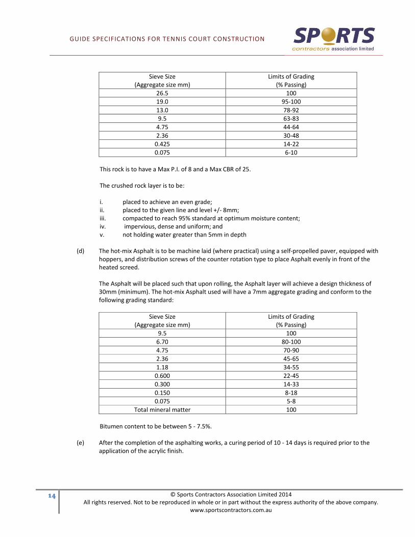
(c) The base layer should be a thickness of 100mm using a 20mm Class 2 F.C.R. The crushed rook should
conform to the following Vic Roads Standard Specification (Section 407):
GUIDE SPECIFICATIONS FOR TENNIS COURT CONSTRUCTION
'� © Sports Contractors Association Limited 2014
All rights reserved. Not to be reproduced in whole or in part without the express authority of the above company.
www.sportscontractors.com.au
Sieve Size
(Aggregate size mm)
Limits of Grading
(% Passing)
26.5 100
19.0 95-100
13.0 78-92
9.5 63-83
4.75 44-64
2.36 30-48
0.425 14-22
0.075 6-10
This rock is to have a Max P.I. of 8 and a Max CBR of 25.
The crushed rock layer is to be:
i. placed to achieve an even grade;
ii. placed to the given line and level +/- 8mm;
iii. compacted to reach 95% standard at optimum moisture content;
iv. impervious, dense and uniform; and
v. not holding water greater than 5mm in depth
(d) The hot-mix Asphalt is to be machine laid (where practical) using a self-propelled paver, equipped with
hoppers, and distribution screws of the counter rotation type to place Asphalt evenly in front of the
heated screed.
The Asphalt will be placed such that upon rolling, the Asphalt layer will achieve a design thickness of
30mm (minimum). The hot-mix Asphalt used will have a 7mm aggregate grading and conform to the
following grading standard:
Sieve Size
(Aggregate size mm)
Limits of Grading
(% Passing)
9.5 100
6.70 80-100
4.75 70-90
2.36 45-65
1.18 34-55
0.600 22-45
0.300 14-33
0.150 8-18
0.075 5-8
Total mineral matter 100
Bitumen content to be between 5 - 7.5%.
(e) After the completion of the asphalting works, a curing period of 10 - 14 days is required prior to the
application of the acrylic finish.
GUIDE SPECIFICATIONS FOR TENNIS COURT CONSTRUCTION
'" © Sports Contractors Association Limited 2014
All rights reserved. Not to be reproduced in whole or in part without the express authority of the above company.
www.sportscontractors.com.au
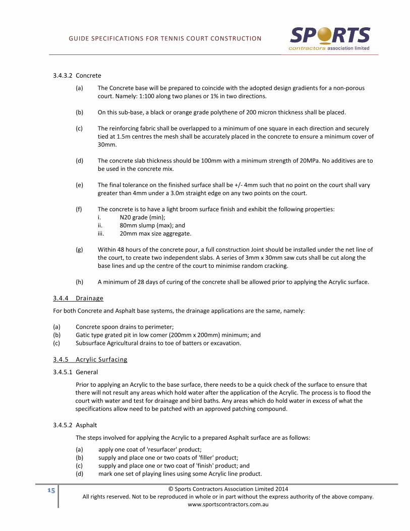
3.4.3.2 Concrete
(a) The Concrete base will be prepared to coincide with the adopted design gradients for a non-porous
court. Namely: 1:100 along two planes or 1% in two directions.
(b) On this sub-base, a black or orange grade polythene of 200 micron thickness shall be placed.
(c) The reinforcing fabric shall be overlapped to a minimum of one square in each direction and securely
tied at 1.5m centres the mesh shall be accurately placed in the concrete to ensure a minimum cover of
30mm.
(d) The concrete slab thickness should be 100mm with a minimum strength of 20MPa. No additives are to
be used in the concrete mix.
(e) The final tolerance on the finished surface shall be +/- 4mm such that no point on the court shall vary
greater than 4mm under a 3.0m straight edge on any two points on the court.
(f) The concrete is to have a light broom surface finish and exhibit the following properties:
i. N20 grade (min);
ii. 80mm slump (max); and
iii. 20mm max size aggregate.
(g) Within 48 hours of the concrete pour, a full construction Joint should be installed under the net line of
the court, to create two independent slabs. A series of 3mm x 30mm saw cuts shall be cut along the
base lines and up the centre of the court to minimise random cracking.
(h) A minimum of 28 days of curing of the concrete shall be allowed prior to applying the Acrylic surface.
3.4.4 Drainage
For both Concrete and Asphalt base systems, the drainage applications are the same, namely:
(a) Concrete spoon drains to perimeter;
(b) Gatic type grated pit in low comer (200mm x 200mm) minimum; and
(c) Subsurface Agricultural drains to toe of batters or excavation.
3.4.5 Acrylic Surfacing
3.4.5.1 General
Prior to applying an Acrylic to the base surface, there needs to be a quick check of the surface to ensure that
there will not result any areas which hold water after the application of the Acrylic. The process is to flood the
court with water and test for drainage and bird baths. Any areas which do hold water in excess of what the
specifications allow need to be patched with an approved patching compound.
3.4.5.2 Asphalt
The steps involved for applying the Acrylic to a prepared Asphalt surface are as follows:
(a) apply one coat of 'resurfacer' product;
(b) supply and place one or two coats of 'filler' product;
(c) supply and place one or two coat of 'finish' product; and
(d) mark one set of playing lines using some Acrylic line product.

GUIDE SPECIFICATIONS FOR TENNIS COURT CONSTRUCTION
'# © Sports Contractors Association Limited 2014
All rights reserved. Not to be reproduced in whole or in part without the express authority of the above company.
www.sportscontractors.com.au
3.4.5.3 Concrete
In the case of a concrete base, the following steps should be used in applying an Acrylic:
(a) acid etch concrete surface and high pressure hose off all residue material;
(b) supply and place concrete 'slurry' or primer coating;
(c) supply and place one or two coats of 'filler' product;
(d) supply and place one or two coats of 'finish' product, and
(e) mark one set of playing lines using Acrylic line product.
3.4.6 Points to Note
In between coatings of Acrylic products, the surface should be checked and remedied for voids, irregularities, roller or
squeegee ridges and cleaned of any loose surface materials.
Applications of 100% Acrylic coatings generally should not be made when ambient temperature is 10 degrees Celsius or
less, rain is imminent and always within the manufacturers specifications and recommendations.
Tolerances: the surface tolerances should be no greater than 4mm over a three meter straight edge in any direction.
GUIDE SPECIFICATIONS FOR TENNIS COURT CONSTRUCTION
'$ © Sports Contractors Association Limited 2014
All rights reserved. Not to be reproduced in whole or in part without the express authority of the above company.
www.sportscontractors.com.au
SECTION 4.0 · BASE OPTIONS
4.1 ASPHALT BASE
4.1.1 General
The general material supply requirements are as follows for the construction of a hot-mix Asphalt base. This base can
be used under Synthetic Acrylic or Synthetic grass. It can also act as a final playing surface.
4.1.2 Preparation of Subgrade
The subgrade will be prepared in accordance with the specification subgrade and will be fully proof rolled prior to any
further works.
4.1.3 Installation of Concrete Border
A concrete kerb/border is to be installed along the high side of the courts(s). This kerb is to be installed to design line
and level +/- 5mm, with the top of the kerb flush with finished surface level. Concrete is to be a minimum width of
150mm and 150mm deep using 20MPa 20mm concrete.
A concrete spoon drain is to be installed along the lower sides of the court(s). This drain will be laid true to line and
level +/- 5mm with the top of the drain flush with finished surface level. The spoon drain is to be a minimum width of
450mm and 25mm deep. The spoon drain is to empty into corner sump pit of dimensions 200 x 200mm. This pit is to
discharge to local storm water pipes.
4.1.4 Installation of Crushed Rock
The crushed rock base is to be built to achieve an even grade to design line and level +/- 8mm and compacted to reach
95% standard. The crushed rock is to be placed and compacted at optimum moisture content. It is advisable that the
rock be delivered plant mixed at this moisture level.
The method for achieving design tolerance shall be by use of motorised grader. Compaction shall be by use of
mechanical roller with a minimum static weight of 3.0 tonnes.
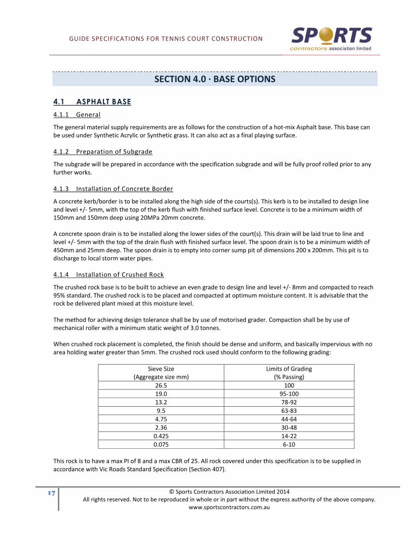
When crushed rock placement is completed, the finish should be dense and uniform, and basically impervious with no
area holding water greater than 5mm. The crushed rock used should conform to the following grading:
Sieve Size
(Aggregate size mm)
Limits of Grading
(% Passing)
26.5 100
19.0 95-100
13.2 78-92
9.5 63-83
4.75 44-64
2.36 30-48
0.425 14-22
0.075 6-10
This rock is to have a max PI of 8 and a max CBR of 25. All rock covered under this specification is to be supplied in
accordance with Vic Roads Standard Specification (Section 407).

GUIDE SPECIFICATIONS FOR TENNIS COURT CONSTRUCTION
'% © Sports Contractors Association Limited 2014
All rights reserved. Not to be reproduced in whole or in part without the express authority of the above company.
www.sportscontractors.com.au
4.1.5 Prime
Hot cutback bitumen shall be sprayed if specified at a minimum rate of 0.8 Litre/m2. Where possible, this bitumen shall
be applied by means of a calibrated road sprayer. Where access does not allow for this method, a hand lance may be
used, but extreme care must be taken to avoid ponding of bitumen. Where ponding does occur, this area shall have a
thin layer of sand or dust applied to soak up excessive bitumen. Care should be taken to protect all concrete and
adjoining surfaces from overspray.
4.1.6 Hot Mix Asphalt
Asphalt shall be delivered hot to site and placed in paver with minimum delay. The paver shall be self-propelled,
equipped with hoppers, distribution screws of the counter rotation type to place asphalt evenly in front of its heated
screed.
The asphalt shall be rolled while hot to achieve design thickness (minimum 30mm) with a self-propelled roller capable
of reversing without backlash.
When completed, the total area shall be checked to ensure a tolerance of +/- 5mm is achieved with no machine or tool
marks. Where such blemishes are found, the area shall be heated and rerolled or tamped with mechanical compactor.
The entire area is to have size 7mm type L hot mix asphalt machine-laid to design grade.
The aggregate grading will conform to the following:
Sieve Size
(Aggregate size mm)
Limits of Grading
(% Passing)
9.5 100
6.70 80-100
4.75 70-90
2.36 45-65
1.18 34-55
0.600 22-45
0.300 14-33
0.150 8-18
0.075 5-8
Total mineral matter 100
Bitumen content to be between 5 - 7.5%.
4.2 CONCRETE
4.2.1 Preparation of Sub Base
A layer of crushed rock or packing sand shall be used to present a uniform sub base to line and level within a tolerance
of +/- 10mm. It is recommended that a laser controlled grader or land plane is used to achieve this tolerance.
4.2.2 Polythene
Black or Orange grade Polythene of 200 micron thickness shall be used under all Rebound Ace and Acrylic slabs. This
shall be held in place with 50mm plastic adhesive tape.
GUIDE SPECIFICATIONS FOR TENNIS COURT CONSTRUCTION
'& © Sports Contractors Association Limited 2014
All rights reserved. Not to be reproduced in whole or in part without the express authority of the above company.
www.sportscontractors.com.au
4.2.3 Installation of Reinforcement
The reinforcing fabric shall be overlapped to minimum of one square in each direction and securely tied at 1.5m
centres. Where possible, consecutive rows of fabric should be "offset" to avoid clusters of welded mesh. A minimum
F52 (or F62 Synthetic Acrylic) welded reinforcing mesh shall be used. All mesh should be clean and free of oil, mud or
rust and placed accurately in the concrete to ensure a minimum cover of 30mm.
4.2.4 Installation of Concrete
All concrete shall be pumped into place by means of a "Squeeze" type pump. Sufficient labour shall be on hand to
roughly place the concrete to desired line and level. A minimum of two "screed hands" shall be on the site to quickly
screed an accurate finish to the slab and avoid overworking and segregation of concrete. The final tolerance on the
finished surface shall be +/-4mm such that no point on the court shall vary greater than 4mm under a 3.0m straight
edge when placed on any two points on the court.
It is imperative to arrange for a constant supply of concrete to avoid cold joints in slab. No additives are to be placed in
concrete mix when Synthetic Acrylic surfacing is intended to be used.
The concrete is to have a dense steel trowelled finish when synthetic grass is used and wood float or broom finish is
preferred for Synthetic Acrylic.
Concrete to be:
(a) N20 grade (min);
(b) 80mm slump (max); and
(c) 20mm max size aggregate.
4.2.5 Joints
4.2.5.1 Synthetic Grass
It is not imperative to construct joints when the slab is to be overlaid with synthetic grass, however sometimes
it is desirable to place 3mm saw cuts in the slab to isolate sections of the pavement.
4.2.5.2 Synthetic Acrylic
A full construction joint should be installed under the net line of court to create two independent slabs.
Within 48 hours of the concrete pour a series of 3mm x 30mm saw cuts shall be cut along the base lines
and up the centre of the court to minimise random cracking.
4.3 BITUMEN SEAL
4.3.1 General
The general material supply requirements are as follows for the construction of a Bitumen Seal base.
This type of construction will give a low cost, medium quality flexible base upon which a Sand Filled Artificial Grass
surface can be laid.
GUIDE SPECIFICATIONS FOR TENNIS COURT CONSTRUCTION
�( © Sports Contractors Association Limited 2014
All rights reserved. Not to be reproduced in whole or in part without the express authority of the above company.
www.sportscontractors.com.au
4.3.2 Preparation of Sub Grade
The sub grade will be prepared in accordance with the specification sub grade and will be fully proof rolled prior to any
further works.
4.3.3 Installation of Concrete Border
A concrete kerb/border is to be installed along the high sides of court. This kerb is to be installed to design level +/-
5mm, with the top of the kerb flush with finished surface level. Concrete is to be a minimum width of 150mm and
150mm deep using 20 MPa 20mm concrete.
A concrete spoon drain is to be installed along the lower sides of the court. This drain will be laid to line and level +/-
5um with the top of the drain flush with finished surface level. The spoon drain is to be a minimum width of 450mm
and I50mm deep.
The spoon drain is to empty into corner sump pit of minimum dimensions 200 x 200mm. This pit is to discharge to local
storm water pipes.
4.3.4 Installation of Crushed Rock
The crushed rock base is to be built to achieve an even grade to design line and level +/- 8mm and compacted to reach
95% standard.
The crushed rock is to be placed and compacted at optimum moisture content (it is advisable that the rock be delivered
plant mixed at this moisture level).
The method for achieving design tolerance shall be by use of motorised grader with a central grading blade of
minimum width 2.4m. Compaction shall be by use of mechanical roller with a minimum static weight of 3.0 tonnes.
When crushed rock placement is completed the finish should be dense and uniform and basically impervious, with no
area holding water greater than 5mm.
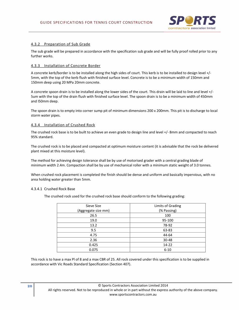
4.3.4.1 Crushed Rock Base
The crushed rock used for the crushed rock base should conform to the following grading:
Sieve Size
(Aggregate size mm)
Limits of Grading
(% Passing)
26.5 100
19.0 95-100
13.2 78-92
9.5 63-83
4.75 44-64
2.36 30-48
0.425 14-22
0.075 6-10
This rock is to have a max Pl of 8 and a max CBR of 25. All rock covered under this specification is to be supplied in
accordance with Vic Roads Standard Specification (Section 407).

GUIDE SPECIFICATIONS FOR TENNIS COURT CONSTRUCTION
�' © Sports Contractors Association Limited 2014
All rights reserved. Not to be reproduced in whole or in part without the express authority of the above company.
www.sportscontractors.com.au
4.3.5 Prime
Hot cutback bitumen shall be sprayed if specified at a minimum rate of 0.8 litre/m2. Where possible this bitumen shall
be applied by means of calibrated road sprayer. Where access does not allow for this method a hand lance may be
used but extreme care must be taken to avoid ponding of bitumen. Where ponding does occur, this area shall have a
thin layer of sand or dust applied to soak up excessive bitumen. Care should be taken to protect all concrete and
adjoining surfaces from overspray.
4.3.6 Hot Mix Asphalt
The entire surface shall be sprayed with hot cutback prime (SP 1000) at a rate of approximately 0.8 litre/m2 . Over this
a thin layer of sand or 5mm aggregate shall be evenly spread at a rate of 50kg/m2. This sand or aggregate shall be fully
rolled into the surface using a roller of minimum weight 3 tonnes. All loose material shall be swept from surface to
achieve a tight homogenous surface.
GUIDE SPECIFICATIONS FOR TENNIS COURT CONSTRUCTION
�� © Sports Contractors Association Limited 2014
All rights reserved. Not to be reproduced in whole or in part without the express authority of the above company.
www.sportscontractors.com.au
SECTION 5.0 · FENCING
5.1 COMMERCIAL TENNIS COURTS COMPLYING WITH AS1725-2010-PART-2
5.1.1 Fence Design Options
(a) Top and bottom pipe rail with 3 mid cables (preferred option)
(b) Top pipe rail only with 3 mid and 1 bottom cable (4 cable wires)
(c) Bottom pipe rail only with 3 mid and 1 top cable (4 cable wires)
(d) Rail-less with corner bracing with 3 mid and 1 top and 1 bottom cable (5 cable wires)
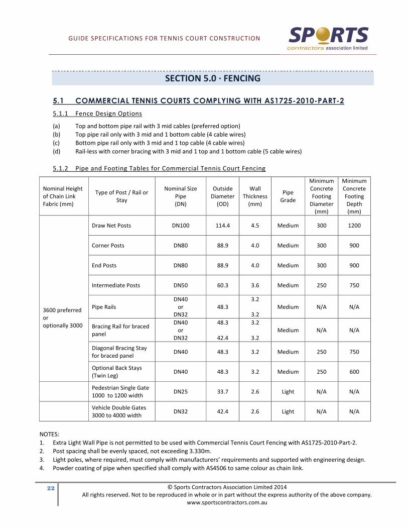
5.1.2 Pipe and Footing Tables for Commercial Tennis Court Fencing
Nominal Height
of Chain Link
Fabric (mm)
Type of Post / Rail or
Stay
Nominal Size
Pipe
(DN)
Outside
Diameter
(OD)
Wall
Thickness
(mm)
Pipe
Grade
Minimum
Concrete
Footing
Diameter
(mm)
Minimum
Concrete
Footing
Depth
(mm)
3600 preferred
or
optionally 3000
Draw Net Posts DN100 114.4 4.5 Medium 300 1200
Corner Posts DN80 88.9 4.0 Medium 300 900
End Posts DN80 88.9 4.0 Medium 300 900
Intermediate Posts DN50 60.3 3.6 Medium 250 750
Pipe Rails
DN40
or
DN32
48.3
3.2
3.2
Medium
N/A N/A
Bracing Rail for braced
panel
DN40
or
DN32
48.3
42.4
3.2
3.2
Medium N/A N/A
Diagonal Bracing Stay
for braced panel DN40 48.3 3.2 Medium 250 750
Optional Back Stays
(Twin Leg) DN40 48.3 3.2 Medium 250 600
Pedestrian Single Gate
1000 to 1200 width DN25 33.7 2.6 Light N/A N/A
Vehicle Double Gates
3000 to 4000 width DN32 42.4 2.6 Light N/A N/A
NOTES:
1. Extra Light Wall Pipe is not permitted to be used with Commercial Tennis Court Fencing with AS1725-2010-Part-2.
2. Post spacing shall be evenly spaced, not exceeding 3.330m.
3. Light poles, where required, must comply with manufacturers’ requirements and supported with engineering design.
4. Powder coating of pipe when specified shall comply with AS4506 to same colour as chain link.

GUIDE SPECIFICATIONS FOR TENNIS COURT CONSTRUCTION
�� © Sports Contractors Association Limited 2014
All rights reserved. Not to be reproduced in whole or in part without the express authority of the above company.
www.sportscontractors.com.au
5.1.3 Preferred Range of Chain Link Fabric for Commercial Tennis Courts
(a) Heavy duty 3600mm high x 45 pitch x 3.15mm wire fabric is preferred.
(b) Chain link fabric shall comply with AS2423.
Preferred Fabric
Height (mm)
Pitch or Mesh
Size (mm)
Core Wire
Diameter (mm) Wire Coating
Selvedge edge of
chain link fabric
Fabric Service
Duty
3600 45 3.15 Heavily Galvanized W10Z (HG) Knuckled both ends
(KK) Heavy Duty
3600 45 3.15 Polyvinyl Chloride (PVC) Knuckled both ends
(KK) Heavy Duty
3600 45 3.15 Fusion Bonded Coated (FBC) Knuckled both ends
(KK) Heavy Duty
NOTES:
1. Standard colours for PVC coatings are Black or Evergreen. PVC is an extruded plastic coating over the base core wire.
2. Standard colour for Fusion Bonded coating is Black. Fusion Bonded is a polymer coating glued to the base core wire.
3. Chain Link shall be secured to the playing side of posts and strained taut between 1.0 to 1.2 kN to ensure the chain link
diamonds cannot separate more than 5mm with a hand squeeze test.
4. Chain link or bottom rail must be set close enough to playing surface to retain tennis balls.
GUIDE SPECIFICATIONS FOR TENNIS COURT CONSTRUCTION
�� © Sports Contractors Association Limited 2014
All rights reserved. Not to be reproduced in whole or in part without the express authority of the above company.
www.sportscontractors.com.au
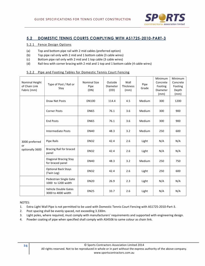
5.2 DOMESTIC TENNIS COURTS COMPLYING WITH AS1725-2010-PART-3
5.2.1 Fence Design Options
(a) Top and bottom pipe rail with 2 mid cables (preferred option)
(b) Top pipe rail only with 2 mid and 1 bottom cable (3 cable wires)
(c) Bottom pipe rail only with 2 mid and 1 top cable (3 cable wires)
(d) Rail-less with corner bracing with 2 mid and 1 top and 1 bottom cable (4 cable wires)
5.2.2 Pipe and Footing Tables for Domestic Tennis Court Fencing
Nominal Height
of Chain Link
Fabric (mm)
Type of Post / Rail or
Stay
Nominal Size
Pipe
(DN)
Outside
Diameter
(OD)
Wall
Thickness
(mm)
Pipe
Grade
Minimum
Concrete
Footing
Diameter
(mm)
Minimum
Concrete
Footing
Depth
(mm)
3000 preferred
or
optionally 3600
Draw Net Posts DN100 114.4 4.5 Medium 300 1200
Corner Posts DN65 76.1 3.6 Medium 300 900
End Posts DN65 76.1 3.6 Medium 300 900
Intermediate Posts DN40 48.3 3.2 Medium 250 600
Pipe Rails DN32 42.4 2.6 Light N/A N/A
Bracing Rail for braced
panel DN32 42.4 2.6 Light N/A N/A
Diagonal Bracing Stay
for braced panel DN40 48.3 3.2 Medium 250 750
Optional Back Stays
(Twin Leg) DN32 42.4 2.6 Light 250 600
Pedestrian Single Gate
1000 to 1200 width DN20 26.9 2.3 Light N/A N/A
Vehicle Double Gates
3000 to 4000 width DN25 33.7 2.6 Light N/A N/A
NOTES:
1. Extra Light Wall Pipe is not permitted to be used with Domestic Tennis Court Fencing with AS1725-2010-Part-3.
2. Post spacing shall be evenly spaced, not exceeding 3.330m.
3. Light poles, where required, must comply with manufacturers’ requirements and supported with engineering design.
4. Powder coating of pipe when specified shall comply with AS4506 to same colour as chain link.
GUIDE SPECIFICATIONS FOR TENNIS COURT CONSTRUCTION
�" © Sports Contractors Association Limited 2014
All rights reserved. Not to be reproduced in whole or in part without the express authority of the above company.
www.sportscontractors.com.au
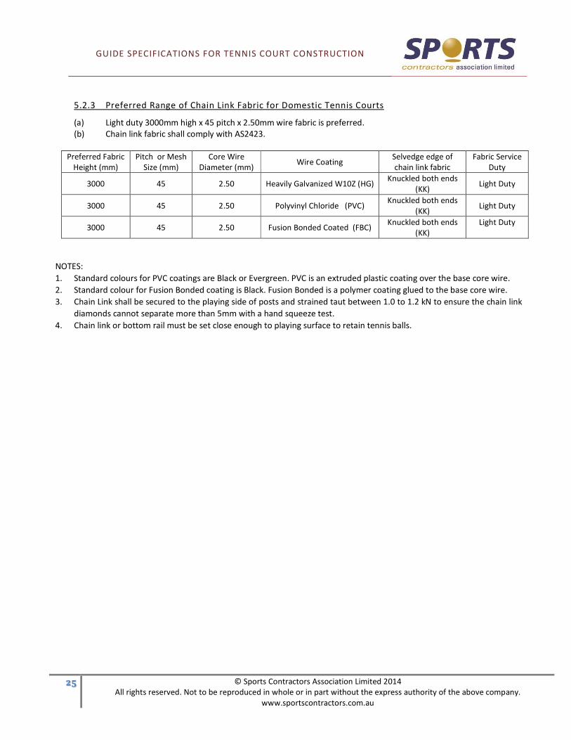
5.2.3 Preferred Range of Chain Link Fabric for Domestic Tennis Courts
(a) Light duty 3000mm high x 45 pitch x 2.50mm wire fabric is preferred.
(b) Chain link fabric shall comply with AS2423.
Preferred Fabric
Height (mm)
Pitch or Mesh
Size (mm)
Core Wire
Diameter (mm) Wire Coating
Selvedge edge of
chain link fabric
Fabric Service
Duty
3000 45 2.50 Heavily Galvanized W10Z (HG) Knuckled both ends
(KK) Light Duty
3000 45 2.50 Polyvinyl Chloride (PVC) Knuckled both ends
(KK) Light Duty
3000 45 2.50 Fusion Bonded Coated (FBC) Knuckled both ends
(KK)
Light Duty
NOTES:
1. Standard colours for PVC coatings are Black or Evergreen. PVC is an extruded plastic coating over the base core wire.
2. Standard colour for Fusion Bonded coating is Black. Fusion Bonded is a polymer coating glued to the base core wire.
3. Chain Link shall be secured to the playing side of posts and strained taut between 1.0 to 1.2 kN to ensure the chain link
diamonds cannot separate more than 5mm with a hand squeeze test.
4. Chain link or bottom rail must be set close enough to playing surface to retain tennis balls.

GUIDE SPECIFICATIONS FOR TENNIS COURT CONSTRUCTION
�# © Sports Contractors Association Limited 2014
All rights reserved. Not to be reproduced in whole or in part without the express authority of the above company.
www.sportscontractors.com.au
5.3 GENERAL FENCING REQUIREMENTS APPLICABLE TO BOTH COMMERCIAL AND
DOMESTIC TENNIS COURTS
5.3.1 Fittings
Fittings for connection of posts, rail and stays shall be either Downee / Elgate or equivalent (hot dip galvanized)
clamp-on fittings and shall be firmly secured to posts, rail and stays with all nuts facing away from playing side of
fence.
5.3.2 Cable and Lacing Wires
Cable and lacing wires shall be the same coating quality as per Chain Link Fabric.
5.3.2.1 Single Strand Helicoil Cable Wires
Shall be 4.0mm core wire strained taut between 1.0 to 1.2 kN and double cross tied to posts with 2.00mm
core wire.
5.3.2.2 Optional Twin Twist Cable Wires
Shall be two strands of 3.15mm core wire twisted together taut between posts to achieve 1.0 to 1.2kN.
5.3.2.2 Lacing Wire
Shall be 2.00mm core wire laced taut through each diamond to all Top and Bottom rails, plus Gate, End
and Corner posts.
5.3.2.3 Ties to Posts
Wire ties to posts shall be 2.00mm core wire single strand or twin 1.57mm to tie chain link firmly to all
intermediate posts, ties shall be located centrally between all cable wires , twisted twice with ends cut
short and folded back flat to posts to avoid risk of injury.
5.3.2.4 “C” Clips to Secure Chain Link to Cable Wires
Either 2.00mm or 2.30mm wire “C” clips are preferred with blunt ends only (to avoid risk of injury). Clips
shall be clipped to all cable wires at 320mm maximum spacing (each 4th diamond).

GUIDE SPECIFICATIONS FOR TENNIS COURT CONSTRUCTION
�$ © Sports Contractors Association Limited 2014
All rights reserved. Not to be reproduced in whole or in part without the express authority of the above company.
www.sportscontractors.com.au
SECTION 6.0 · LIGHTING
6.1 GENERAL
A Town Planning permit may be required for residential tennis court lighting. (Refer to the Code of Practice Private
Tennis Court Development).
To minimise light spillage, environmental style box lights are recommended for residential tennis court lighting.
6.2 THE TUNGSTEN HALOGEN SYSTEM
Pole locations: Six light poles are required, either side mounted or corner mounted.
Required footings: The required reinforced foundation varies with pole height, fencing, soil conditions etc., and
should be established by a qualified engineer. As a guide, a reinforced concrete foundation of
300mm diameter by 1000mm depth in normal ground conditions should be satisfactory.
Luminaries: General wide distribution – 1500W Tungsten halogen floodlights. Either 6-8 units may be
incorporated into the light design, depending on desired light levels.
Mounting height: 6.7m (minimum).
Pole Specifications: 65-80mm inside diameter tubular steel pipe.
Weight Per unit: 7 - 10 kg.
6.3 THE METAL HALIDE SYSTEM
Pole locations: (a) two per side, each 7m from net line, or
(b) three per side, two opposite net line, and two per side each 11 metres from netline.
Required footings: The required concrete foundation varies with pole height, fencing, soil conditions etc., and
should be established by a qualified engineer. A concrete foundation of 400mm diameter by
1000mm depth in normal ground conditions is recommended for this system.
Mounting Height: (a) 6.5m (min) for 3 per side system, and
(b) 6.7m (min) for 2 per side system.
Pole Specifications: 80mm minimum, inside diameter tubular steel pipe or square section tubing.
Weight per unit: 30-35kg with control gear.
GUIDE SPECIFICATIONS FOR TENNIS COURT CONSTRUCTION
�% © Sports Contractors Association Limited 2014
All rights reserved. Not to be reproduced in whole or in part without the express authority of the above company.
www.sportscontractors.com.au
SECTION 7.0 · ACCESSORIES
7.1 NET POSTS
Net posts should be round or square, with internal or external winding mechanisms. The centre of the posts shall be
0.91m outside the court side lines. The height of the posts shall be such that the top of the metal cable shall be 1.07m
above the playing surface at the net post location, and 900mm above the playing surface at the court centre.
Net posts (or sleeves for net posts) shall be placed in a 20MPa concrete footing, being 350mm diameter and 600mm
depth (minimum), but may vary relative to subgrade conditions.
7.2 NET
Generally 760mm drop or full drop. Refer to manufacturers guidelines relative to various net qualities, and attachment
to net posts.
7.3 NET CENTRE STRAP
Woven centre strap with suitable steel attachment set in concrete footing (200mm diameter, 150mm depth), central to
net line.
GUIDE SPECIFICATIONS FOR TENNIS COURT CONSTRUCTION
�& © Sports Contractors Association Limited 2014
All rights reserved. Not to be reproduced in whole or in part without the express authority of the above company.
www.sportscontractors.com.au
SECTION 8.0 · TENNIS COURT DRAW CURTAINS
8.1 GENERAL DESCRIPTION
Netting curtains around tennis courts are primarily used to divide adjacent courts or keep balls within the playing area
in a landscaped garden situation, which would aesthetically suffer from the provision of a chain wire mesh fence.
The curtains should be designed with a height to suit the location, generally 3.05m or 3.65m and with appropriate splits
or gaps to suit the court's access points and support structure. The number of individual splits in the curtains should be
minimized to eliminate potential points where balls will travel beyond the court perimeter.
Net curtains can be made to any size (height and length) and any shape. For example, if a curtain was running along a
sloping wall the base could be tailored to match the slope. All curtain lengths are made 15% longer than the opening
width to allow for the 'curtaining' effect. Longer curtains those exceeding 15m - can allow 10%.
Nets will come with support clips allowing them to be clipped to the upper support cable after the cable has been
installed and fully tensioned. This connection feature also allows for the nets to be easily removed for repairs,
entertainment or seasonal requirements.
The bottom cord will generally be supplied with a lead core rope, which has been machine attached to it, in order to
minimize movement in windy conditions. Under certain circumstances when high winds are expected, the lead
weighting of the bottom cord must be increased or the bottom cord has to be restrained by a ground cable and
attachment clips.
8.2 NET MATERIAL & MANUFACTURE
Invariably black or dark green polyethylene netting is used with a maximum 44mm square hole in a minimum of 36 ply.
The machine made netting will be always converted to 'the square' and cut into the sizes specified by the designer.
Each individual net will have a machine overlocked edge which includes a polypropylene rope on all sides except the
bottom cord, which will have a lead core polypropylene rope spliced to the side rope at each bottom corner. The lead
core rope will then be overlocked at least twice for improved life and wear resistance.
Nets are supplied with Velcro ties to join them when deployed. Additional Velcro ties are available to tie the nets back
when not in use.
8.3 SUPPORT STRUCTURES
In most applications, the draw curtains are supported on a highly tensioned cable which should be from a minimum of
5mm diameter fibre core galvanised steel wire rope. (Single strand fencing wire can be used but it is not recommended
as it tends to fatigue over time.)
Support cables are generally terminated on galvanised or painted, powder coated square or round posts. The
termination points on the pole will generally be a welded half chain link or similar fixing point. In some applications
steel wall plates with a connection loop and a minimum of four masonry fixings can be used to fix a cable to a wall or
column.
When wall plates are used they should be a minimum of 100mm square and 10mm thick, with four fixing holes. The
fixing method and selection of fastener will be the decision of the site engineer. Caution must be applied to any wall
fixing to block, brick or cavity walls. In general, suitable masonry fixings can be found for concrete slab walls.

GUIDE SPECIFICATIONS FOR TENNIS COURT CONSTRUCTION
�( © Sports Contractors Association Limited 2014
All rights reserved. Not to be reproduced in whole or in part without the express authority of the above company.
www.sportscontractors.com.au
On a tennis court, pole spans can be around 16m maximum, which will allow a single span base line net. The sideline
nets will require at least one central support for the net cable. This can be achieved by using a saddle or similar fixing
mechanism on a light pole in line with the cable run or a secondary pole.
The main corner support poles will be a minimum of 100mm square or round heavy walled tube a minimum of 1m into
the ground. The foundation design must be approved by the site engineer and be suitable for the site ground structure.
Rocky or uncompacted fill conditions will require specific variation to ensure the support cable can be tensioned to
approximately 500kgs load.
Installers should angle the poles away from the cable centre at least 2 degrees to allow for flexing when the cable is
tight. This will ensure the poles are as vertical as possible when the cable is fully tensioned.
The best results will come from minimum cable sag when the net is installed and covering the opening. This minimum
should be around 100mm at maximum span.
Secondary support poles could be from 65mm NB material or the same material as selected for the main corner poles.