guide to bare base mechanical systems, part i · guide to bare base mechanical systems part i - air...
TRANSCRIPT
AIR FORCE HANDBOOK 10-222, Volume 12 1 September 1999
DEPARTMENT OF THE AIR FORCE
GUIDE TO BARE BASEMECHANICAL SYSTEMS, PART I

Report Documentation Page Form ApprovedOMB No. 0704-0188
Public reporting burden for the collection of information is estimated to average 1 hour per response, including the time for reviewing instructions, searching existing data sources, gathering andmaintaining the data needed, and completing and reviewing the collection of information. Send comments regarding this burden estimate or any other aspect of this collection of information,including suggestions for reducing this burden, to Washington Headquarters Services, Directorate for Information Operations and Reports, 1215 Jefferson Davis Highway, Suite 1204, ArlingtonVA 22202-4302. Respondents should be aware that notwithstanding any other provision of law, no person shall be subject to a penalty for failing to comply with a collection of information if itdoes not display a currently valid OMB control number.
1. REPORT DATE 01 SEP 1999
2. REPORT TYPE N/A
3. DATES COVERED -
4. TITLE AND SUBTITLE Guide To Bare Base Mechanical Systems Part I - Air Force Handbook10-222, Volume 12
5a. CONTRACT NUMBER
5b. GRANT NUMBER
5c. PROGRAM ELEMENT NUMBER
6. AUTHOR(S) 5d. PROJECT NUMBER
5e. TASK NUMBER
5f. WORK UNIT NUMBER
7. PERFORMING ORGANIZATION NAME(S) AND ADDRESS(ES) Secretary Of The Air Force Washington, DC
8. PERFORMING ORGANIZATIONREPORT NUMBER
9. SPONSORING/MONITORING AGENCY NAME(S) AND ADDRESS(ES) 10. SPONSOR/MONITOR’S ACRONYM(S)
11. SPONSOR/MONITOR’S REPORT NUMBER(S)
12. DISTRIBUTION/AVAILABILITY STATEMENT Approved for public release, distribution unlimited
13. SUPPLEMENTARY NOTES
14. ABSTRACT
15. SUBJECT TERMS
16. SECURITY CLASSIFICATION OF: 17. LIMITATION OF ABSTRACT
UU
18. NUMBEROF PAGES
72
19a. NAME OFRESPONSIBLE PERSON
a. REPORT unclassified
b. ABSTRACT unclassified
c. THIS PAGE unclassified
Standard Form 298 (Rev. 8-98) Prescribed by ANSI Std Z39-18
BY ORDER OF THE AIR FORCE HANDBOOK 10-222, VOLUME 12SECRETARY OF THE AIR FORCE 1 SEPTEMBER 1999
OPERATIONS
GUIDE TO BARE BASE MECHANICAL SYSTEMSPART I
NOTICE: This publication is available digitally on the SAF/AAD WWWsite at: http://afpubs.hq.af.mil. If you lack access, contact your PublishingDistribution Office (PDO).OPR: HQ AFCESA/CEXR (Major Gregory A. Cummings)Certified by: HQ AFCESA/CEX (Colonel Bruce F. Mc Connell)Pages 71/Distribution: F and X
This handbook is designed to assist you in setting up and operating themechanical systems commonly encountered during bare base operations.Specifically, the M-80 boiler, Preway heater, environmental control unit, 150cubic foot refrigeration unit, 1200 cubic foot refrigeration unit, and mobilewater chiller will be discussed. This handbook addresses, as appropriate, siteselection and layout; major components; set up, operation and shutdown ofthe various systems. When coupled with information contained in theapplicable technical orders and AFPAM 10-219, Vol. 5, Bare BaseConceptual Planning Guide, and instruction received at Silver Flag trainingsites, personnel should be capable of effectively setting up and operating theequipment under contingency conditions. Information in this handbookassumes the reader has basic familiarity with bare base-related mechanicalsystems. If this is not the case, consult the technical orders and attend SilverFlag training.
PageINTRODUCTION......................................................................................................5M-80 BOILER.............................................................................................................7PREWAY HEATER................................................................................................25ENVIRONMENTAL CONTROL UNIT .............................................................34

AFH 10-222 Volume 12, Part I 1 September 19992
150 CUBIC FOOT REFRIGERATION UNIT ...................................................421200 CUBIC FOOT REFRIGERATION UNIT .................................................56MOBILE WATER CHILLER................................................................................61
Figures
1. M-80 Boiler........................................................................................................72. Drum Fill Adapter Assembly and Flexible Hoses ......................................83. Water Pump and Suction Line........................................................................94. Water Vessel......................................................................................................95. Burner Assembly.............................................................................................106. Blower Assembly............................................................................................117. Control Box Assembly...................................................................................118. Sight Glass Assembly.....................................................................................129. Transformer and Ignition Cables..................................................................1210. M-80 Heater Water Hose Connections.......................................................1411. Elbow, Smoke Stack and Guard Assembly ................................................1412. Drum Fill Adapter in Fuel Container...........................................................1513. Fuel Line Connections...................................................................................1614. Electrical Connections...................................................................................1615. Load Limit Switch ..........................................................................................1716. Manual Fuel Valve..........................................................................................1717. Reset Button on Flame Safeguard Control .................................................1818. Water Pump Primer Coupling.......................................................................1919. Fuel Pressure Gauge.......................................................................................2120. Water Temperature Gauge ............................................................................2221. Fuel Line Stowage Position ..........................................................................2422. Preway Heater..................................................................................................2523. Siphon Assembly ............................................................................................2624. Control Valve...................................................................................................2725. Stove Pipe Components .................................................................................2726. Stove Pipe Assembly......................................................................................2927. Siphon Assembly Placement.........................................................................3028. Position of Siphon Assembly During Fuel Can Change Out ..................32
AFH 10-222 Volume 12, Part I 1 September 1999 3
29. A/E32C-39 Environmental Control Unit ....................................................3430. Flexible Duct Connection..............................................................................3631. Control Panel...................................................................................................3732. Electrical Connection Receptacle.................................................................3833. Manually-Operated Damper..........................................................................3934. Duct Storage Racks ........................................................................................4035. 150 Cubic Foot Refrigeration Box...............................................................4236. Mechanical Refrigeration Equipment..........................................................4337. Control Panel...................................................................................................4438. Temperature and Pressure Gauges...............................................................4539. Condenser Coil ................................................................................................4540. Condenser Fan.................................................................................................4641. Evaporator Coil ...............................................................................................4642. Evaporator Fan ................................................................................................4743. Fan Motor.........................................................................................................4744. Receiver Tank..................................................................................................4845. Compressor......................................................................................................4846. Condenser Section Gasket Seal....................................................................5047. Valve Locations .............................................................................................5148. Defrost Cycle Timer ......................................................................................5249. Cable Routing..................................................................................................5350. 1200 Cubic Foot Refrigeration Box.............................................................5751. Floor Screed Sections ....................................................................................5752. Floor, Wall, and Ceiling Locking Mechanisms .........................................5853. Wall and Corner Panels .................................................................................5954. Ceiling Panels ..................................................................................................6055. Mobile Water Chiller......................................................................................6156. Support Kit Items ............................................................................................6257. Chiller Hose Connections Points .................................................................6458. Hose Connections ...........................................................................................6459. Quick-Disconnect Fuel Fitting .....................................................................6560. START RUN Water Control.........................................................................6761. Toggle Switch, Choke, Pneumatic Timer Switch, and Starter Button ..6862. 12 VOLT INPUT FOR STARTING Connection .....................................70

AFH 10-222 Volume 12, Part I 1 September 19994
Tables
1. M-80 Pre-Op Inspections..............................................................................202. Water Heater Operational Checks................................................................223. Pre-Operational Checks for the 150 CF Refrigeration Unit ....................544. Operational Checks for the 150 CF Refrigeration Unit............................545. Water Chiller Pre-Operational Checks........................................................666. Operational Checks for the Water Chiller...................................................70

AFH 10-222 Volume 12, Part I 1 September 1999 5
INTRODUCTION
GUIDE TO BARE BASE MECHANICAL SYSTEMS
PURPOSE OF BOOKLET
This handbook addresses the procedures used to set up and operate the M-80boiler, Preway heater, environmental control unit, 150 cubic foot refrigerationunit, 1200 cubic foot refrigeration unit, and the mobile water chiller. It ismeant to be used by civil engineering heating, ventilation and airconditioning (HVAC) personnel in performing their beddown andsustainment mission taskings under contingency conditions. Users of thisbooklet are assumed to have a basic knowledge of bare base assets and theirfunction---readers without this fundamental knowledge should review thebelow listed technical orders; AFPAM 10-219, Volume 5, Bare BaseConceptual Planning Guide; AFH 10-222, Volume 1, Guide to Bare BaseDevelopment; and AFH 10-222, Volume 2, Guide to Bare Base Assets.
TO 40P1-6-2-1, Bath Unit
TM 5-4520-235-13, Preway 70,000 BTU Space Oil-Fired Tent Heater
TO 35E9-163-1, Air Conditioner, Type A/E 32C-39
TO 35E9-274-1/-4, 1200 CF Refer
TM 5-4110-240-13 & P, 150 CF Refer
TM 10-4130-239-14, Small Mobile Water Chiller
TM 5-4110-239-14, Refrigeration Unit, 5000 BTU/HR

AFH 10-222 Volume 12, Part I 1 September 19996
This handbook is designed to augment, not replace, the system’s technicalorders. This booklet will not address the details of operator or organizationalmaintenance and repair of the various equipment items. Refer to theappropriate technical orders for warnings, cautions, and maintenance andtroubleshooting information.
AFH 10-222 Volume 12, Part I 1 September 1999 7
M-80 BOILER
Characteristics
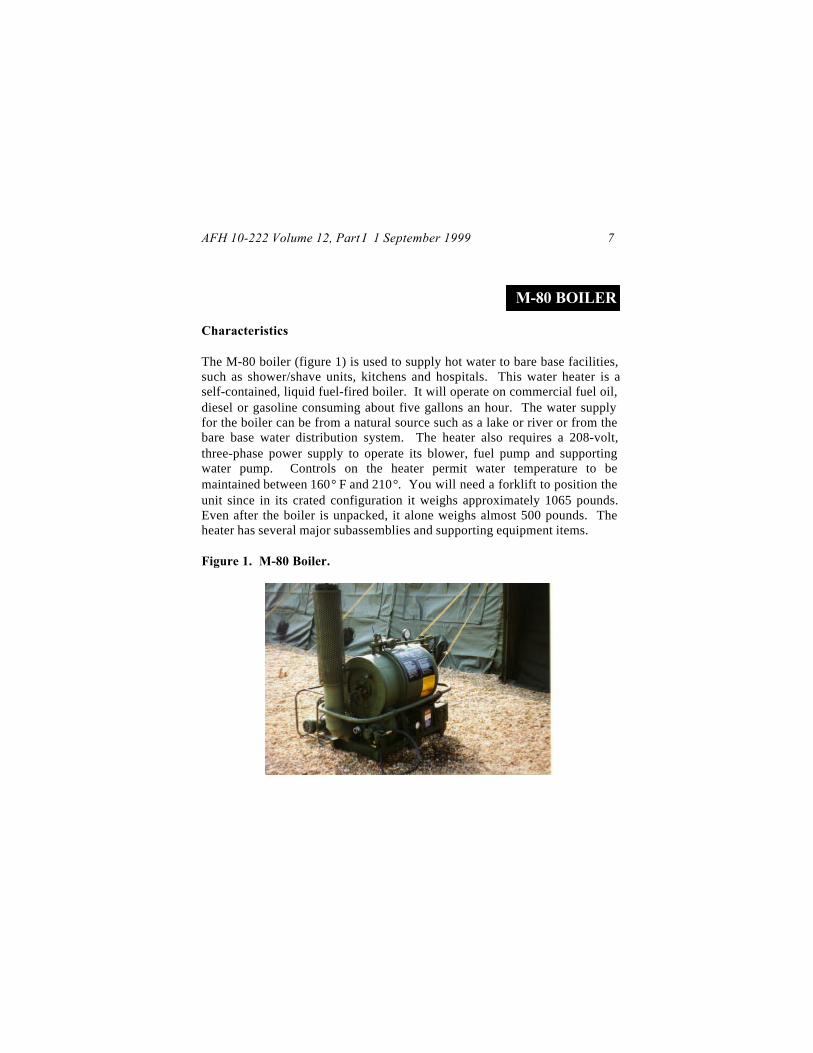
The M-80 boiler (figure 1) is used to supply hot water to bare base facilities,such as shower/shave units, kitchens and hospitals. This water heater is aself-contained, liquid fuel-fired boiler. It will operate on commercial fuel oil,diesel or gasoline consuming about five gallons an hour. The water supplyfor the boiler can be from a natural source such as a lake or river or from thebare base water distribution system. The heater also requires a 208-volt,three-phase power supply to operate its blower, fuel pump and supportingwater pump. Controls on the heater permit water temperature to bemaintained between 160° F and 210°. You will need a forklift to position theunit since in its crated configuration it weighs approximately 1065 pounds.Even after the boiler is unpacked, it alone weighs almost 500 pounds. Theheater has several major subassemblies and supporting equipment items.
Figure 1. M-80 Boiler.

AFH 10-222 Volume 12, Part I 1 September 19998
Fuel System. Fuel is commonly provided in 55-gallon drums (5-gallon jerrycans also can be used) and fed to the heater through a drum fill adapterassembly and flexible hose assemblies (figure 2).
Figure 2. Drum Fill Adapter Assembly and Flexible Hoses.
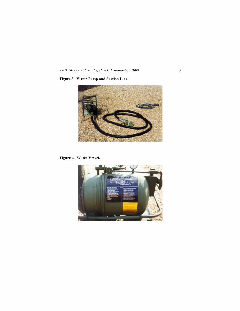
Water Pump and Suction Line (figure 3). A 20 gpm, electrically driven pumpis provided to pump water from a source such as a lake or river or from anonion tank to the heater. A 25-foot, 1-inch inside diameter hose with astrainer assembly on one end attaches to the intake side of the pump andserves as the suction line from the water source. The pump is connected tothe water heater using a 6-foot, 1 ½-inch inside diameter hose.
Power Cable Assembly. The power cable assembly consists of two cablesthat extend from the power source (3kW generator or power distributionpanel) to the heater. The short cable connects to the power source while thelonger cable connects to the short cable, the water pump, and the heater itself.
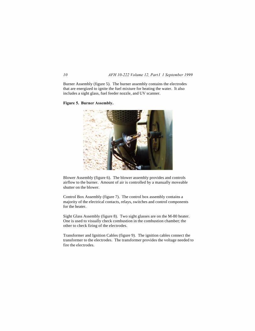
Water Vessel (figure 4). The water vessel is basically the container holdingthe water being heated. It holds approximately 24 gallons.
AFH 10-222 Volume 12, Part I 1 September 1999 9
Figure 3. Water Pump and Suction Line.
Figure 4. Water Vessel.
AFH 10-222 Volume 12, Part I 1 September 199910
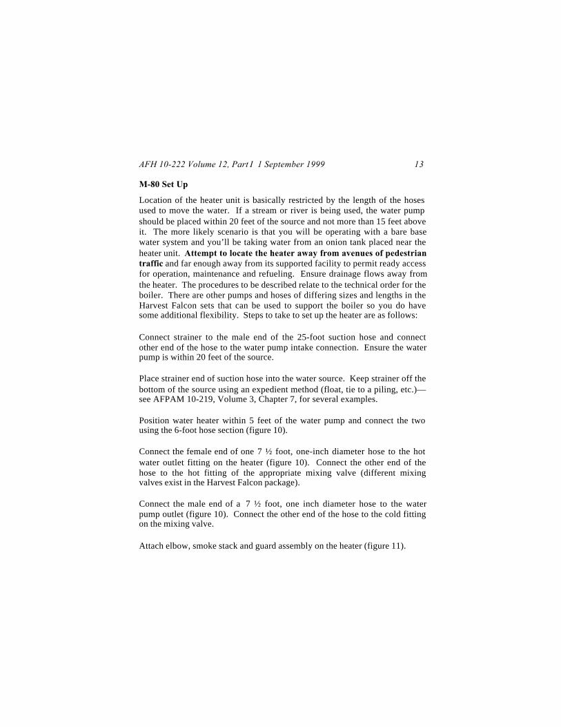
Burner Assembly (figure 5). The burner assembly contains the electrodesthat are energized to ignite the fuel mixture for heating the water. It alsoincludes a sight glass, fuel feeder nozzle, and UV scanner.
Figure 5. Burner Assembly.
Blower Assembly (figure 6). The blower assembly provides and controlsairflow to the burner. Amount of air is controlled by a manually moveableshutter on the blower.
Control Box Assembly (figure 7). The control box assembly contains amajority of the electrical contacts, relays, switches and control componentsfor the heater.
Sight Glass Assembly (figure 8). Two sight glasses are on the M-80 heater.One is used to visually check combustion in the combustion chamber; theother to check firing of the electrodes.
Transformer and Ignition Cables (figure 9). The ignition cables connect thetransformer to the electrodes. The transformer provides the voltage needed tofire the electrodes.

AFH 10-222 Volume 12, Part I 1 September 1999 11
Figure 6. Blower Assembly.
Figure 7. Control Box Assembly.

AFH 10-222 Volume 12, Part I 1 September 199912
Figure 8. Sight Glass Assembly.
Figure 9. Transformer and Ignition Cables.
AFH 10-222 Volume 12, Part I 1 September 1999 13
M-80 Set Up
Location of the heater unit is basically restricted by the length of the hosesused to move the water. If a stream or river is being used, the water pumpshould be placed within 20 feet of the source and not more than 15 feet aboveit. The more likely scenario is that you will be operating with a bare basewater system and you’ll be taking water from an onion tank placed near theheater unit. Attempt to locate the heater away from avenues of pedestriantraffic and far enough away from its supported facility to permit ready accessfor operation, maintenance and refueling. Ensure drainage flows away fromthe heater. The procedures to be described relate to the technical order for theboiler. There are other pumps and hoses of differing sizes and lengths in theHarvest Falcon sets that can be used to support the boiler so you do havesome additional flexibility. Steps to take to set up the heater are as follows:
Connect strainer to the male end of the 25-foot suction hose and connectother end of the hose to the water pump intake connection. Ensure the waterpump is within 20 feet of the source.
Place strainer end of suction hose into the water source. Keep strainer off thebottom of the source using an expedient method (float, tie to a piling, etc.)—see AFPAM 10-219, Volume 3, Chapter 7, for several examples.
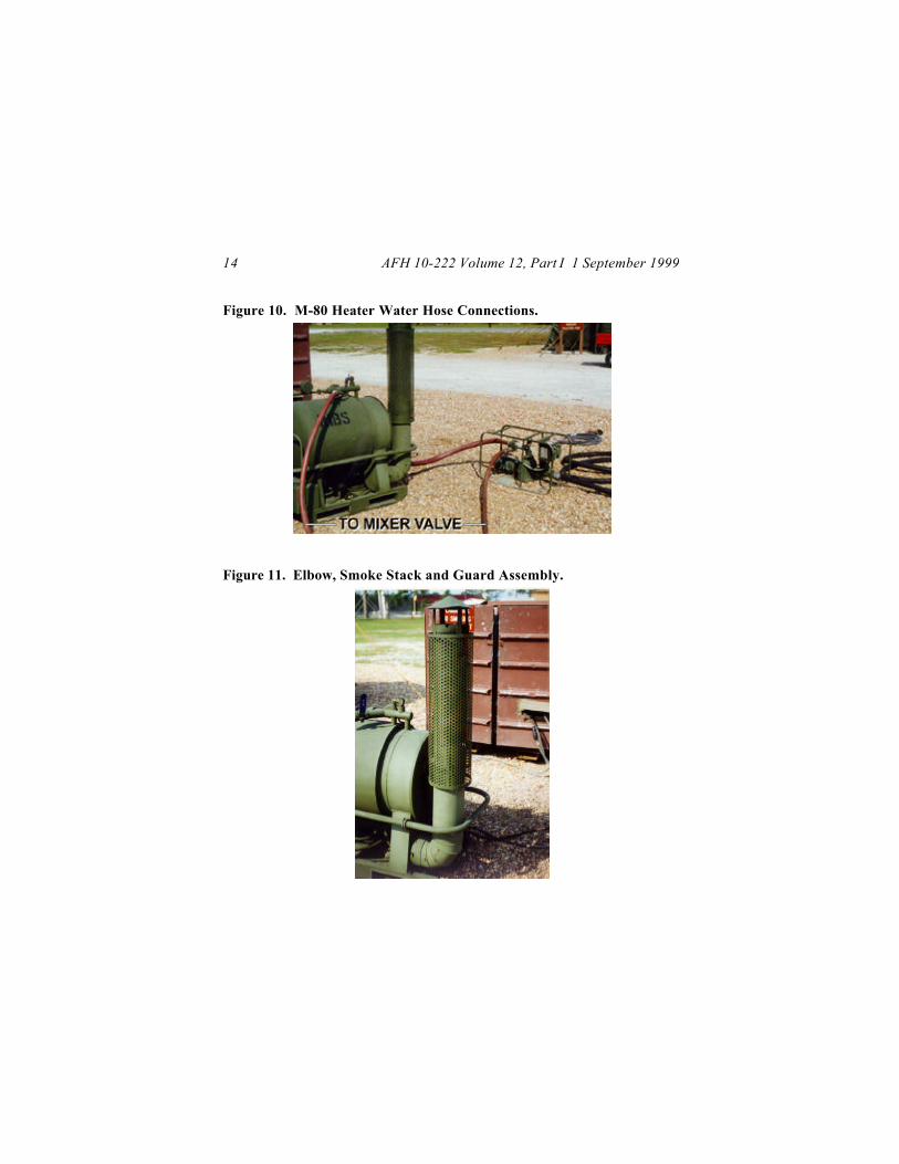
Position water heater within 5 feet of the water pump and connect the twousing the 6-foot hose section (figure 10).
Connect the female end of one 7 ½ foot, one-inch diameter hose to the hotwater outlet fitting on the heater (figure 10). Connect the other end of thehose to the hot fitting of the appropriate mixing valve (different mixingvalves exist in the Harvest Falcon package).
Connect the male end of a 7 ½ foot, one inch diameter hose to the waterpump outlet (figure 10). Connect the other end of the hose to the cold fittingon the mixing valve.
Attach elbow, smoke stack and guard assembly on the heater (figure 11).
AFH 10-222 Volume 12, Part I 1 September 199914
Figure 10. M-80 Heater Water Hose Connections.
Figure 11. Elbow, Smoke Stack and Guard Assembly.
AFH 10-222 Volume 12, Part I 1 September 1999 15
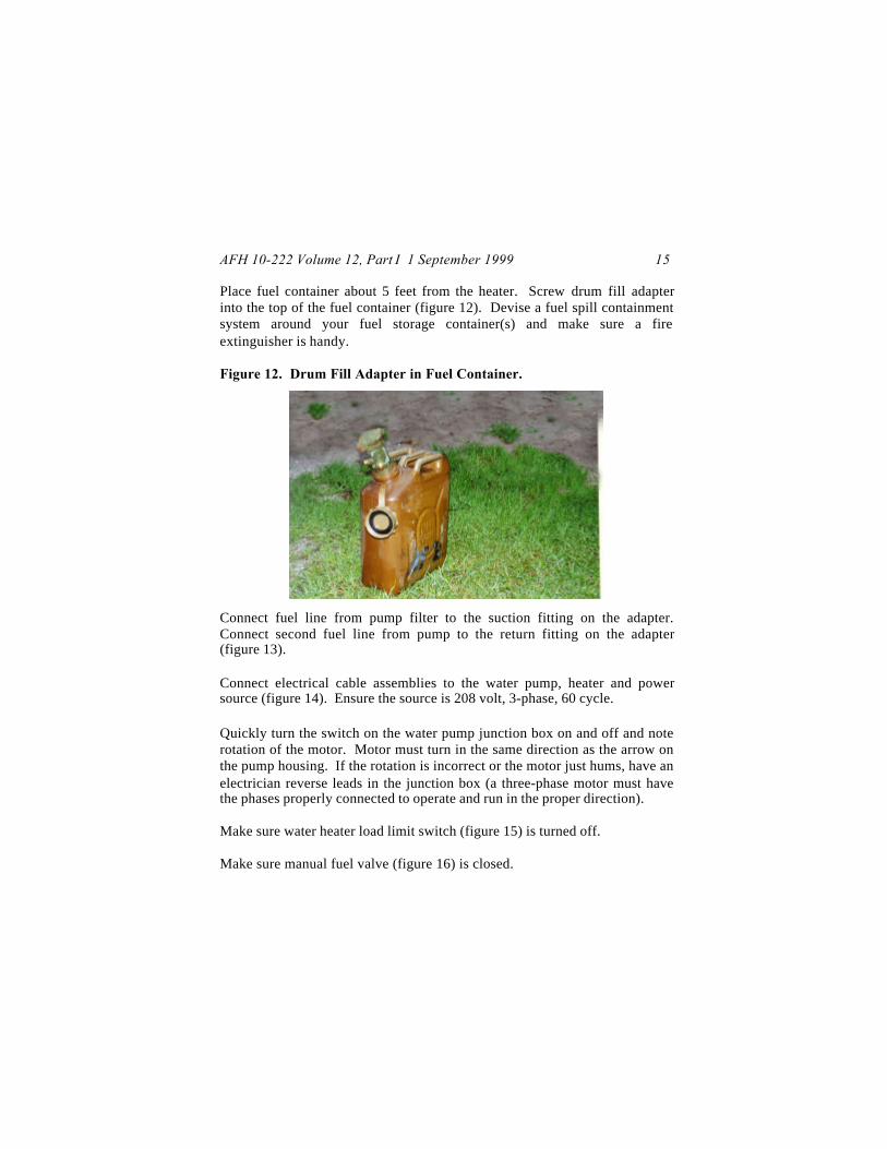
Place fuel container about 5 feet from the heater. Screw drum fill adapterinto the top of the fuel container (figure 12). Devise a fuel spill containmentsystem around your fuel storage container(s) and make sure a fireextinguisher is handy.
Figure 12. Drum Fill Adapter in Fuel Container.
Connect fuel line from pump filter to the suction fitting on the adapter.Connect second fuel line from pump to the return fitting on the adapter(figure 13).
Connect electrical cable assemblies to the water pump, heater and powersource (figure 14). Ensure the source is 208 volt, 3-phase, 60 cycle.
Quickly turn the switch on the water pump junction box on and off and noterotation of the motor. Motor must turn in the same direction as the arrow onthe pump housing. If the rotation is incorrect or the motor just hums, have anelectrician reverse leads in the junction box (a three-phase motor must havethe phases properly connected to operate and run in the proper direction).
Make sure water heater load limit switch (figure 15) is turned off.
Make sure manual fuel valve (figure 16) is closed.

AFH 10-222 Volume 12, Part I 1 September 199916
Figure 13. Fuel Line Connections.
Figure 14. Electrical Connections.

AFH 10-222 Volume 12, Part I 1 September 1999 17
Figure 15. Load Limit Switch.
Figure 16. Manual Fuel Valve.

AFH 10-222 Volume 12, Part I 1 September 199918
Press the reset button on the flame safeguard control (figure 17) inside thecontrol box assembly.
Figure 17. Reset Button on Flame Safeguard Control.
Open the blower shutter on the blower assembly about half way.
Open the fuel pump primer plug and fill the fuel pump with fuel.
Ensure water heater drain cock is closed.
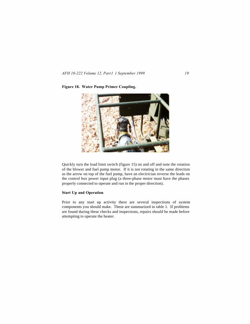
Prime the water pump by filling the coupling on top of the pump with water(figure 18). Ensure plug is placed back into coupling. Close the valve on thetop of the pump that allows water to go to the mixing valve.
Open the faucet on the top of the water vessel and turn on the pump. Allowvessel to fill until water comes out of the faucet, then close the faucet andturn the pump off.
AFH 10-222 Volume 12, Part I 1 September 1999 19
Figure 18. Water Pump Primer Coupling.
Quickly turn the load limit switch (figure 15) on and off and note the rotationof the blower and fuel pump motor. If it is not rotating in the same directionas the arrow on top of the fuel pump, have an electrician reverse the leads onthe control box power input plug (a three-phase motor must have the phasesproperly connected to operate and run in the proper direction).
Start Up and Operation
Prior to any start up activity there are several inspections of systemcomponents you should make. These are summarized in table 1. If problemsare found during these checks and inspections, repairs should be made beforeattempting to operate the heater.
AFH 10-222 Volume 12, Part I 1 September 199920
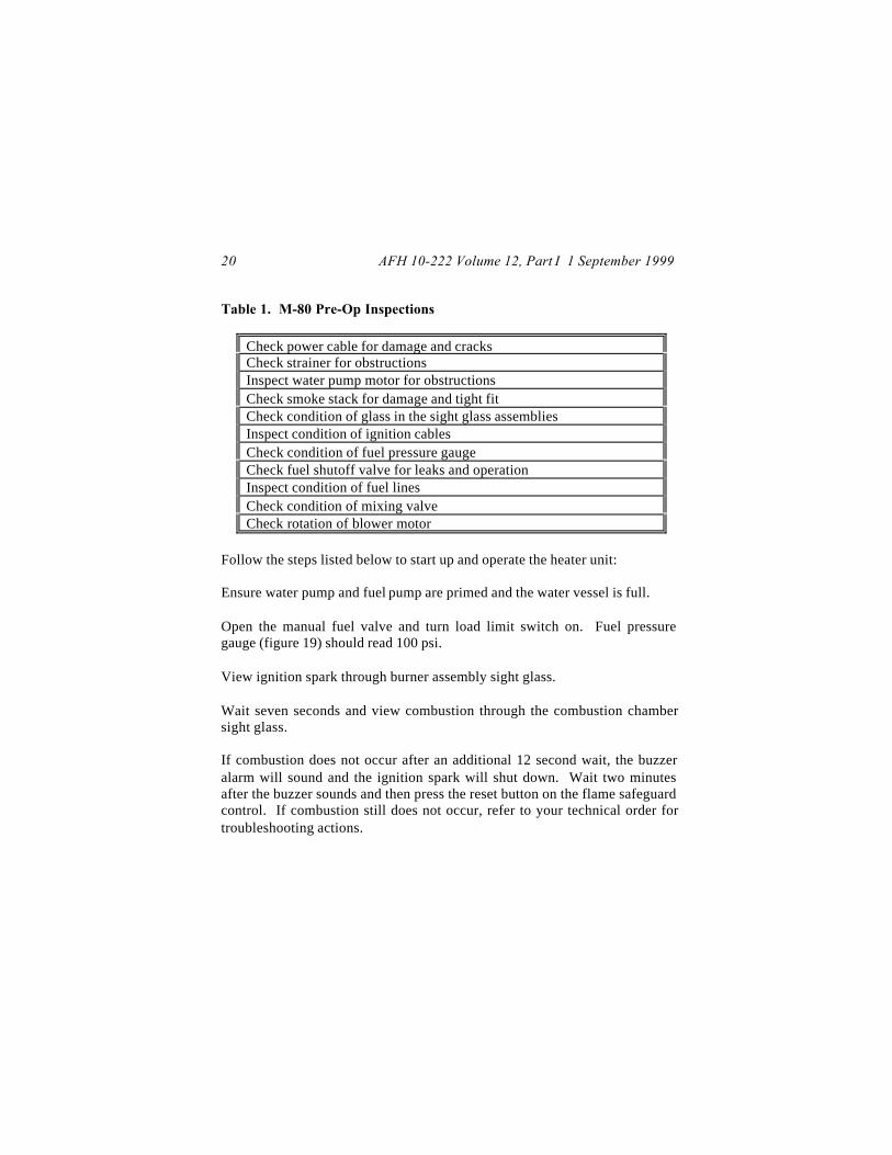
Table 1. M-80 Pre-Op Inspections
Check power cable for damage and cracksCheck strainer for obstructionsInspect water pump motor for obstructionsCheck smoke stack for damage and tight fitCheck condition of glass in the sight glass assembliesInspect condition of ignition cablesCheck condition of fuel pressure gaugeCheck fuel shutoff valve for leaks and operationInspect condition of fuel linesCheck condition of mixing valveCheck rotation of blower motor
Follow the steps listed below to start up and operate the heater unit:
Ensure water pump and fuel pump are primed and the water vessel is full.
Open the manual fuel valve and turn load limit switch on. Fuel pressuregauge (figure 19) should read 100 psi.
View ignition spark through burner assembly sight glass.
Wait seven seconds and view combustion through the combustion chambersight glass.
If combustion does not occur after an additional 12 second wait, the buzzeralarm will sound and the ignition spark will shut down. Wait two minutesafter the buzzer sounds and then press the reset button on the flame safeguardcontrol. If combustion still does not occur, refer to your technical order fortroubleshooting actions.

AFH 10-222 Volume 12, Part I 1 September 1999 21
If necessary, slowly open the air shutter on the blower assembly until exhaustgasses are transparent and smokeless.
Figure 19. Fuel Pressure Gauge.
Ensure the water pump is on and the water pump valve is open. The valve onthe top of the water vessel controlling hot water flow (water heater outletvalve) to the mixer valve should be closed.
Wait until the temperature gauge (figure 20) shows 160 degrees Fahrenheitand open the water heater outlet valve.
Open a valve at a dispensing point (shower, sink, etc). Adjust mixing valvetemperature control to desired water temperature.
During operation of the heater several continual system checks should bemade. They are listed in table 2.

AFH 10-222 Volume 12, Part I 1 September 199922
Figure 20. Water Temperature Gauge.
Table 2. Water Heater Operational Checks.
Check exhaust gasses for clearness. Adjust air shutter as necessaryCheck temperature gauge, keep temperature between 160°F and190°FCheck fuel pressure gauge, maintain 90 psi to 100 psiInspect fuel lines for leaks or damagesCheck mixing valve for leaks and temperature gauge problems
Shutdown
Turn off the fuel valve, load limit switch and water pump.
If the heater is not going to be used for several days or more, also accomplishthe following:
Remove the fuel feed hose from the fuel drum adapter and place the end ofthe hose into a quart container.
AFH 10-222 Volume 12, Part I 1 September 1999 23
Fill the quart container with diesel fuel.
Turn on the load limit switch and operate the unit until the quart container isalmost empty. Then close the fuel valve and let the heater operate until thecombustion flame goes out.
Turn off the load limit switch.
Reconstitution
Perform shutdown procedures above.
Disconnect power cable from water heater and water pump.
Retrieve suction line from the water source and disconnect the strainer.
Disconnect and drain all water hoses, and water vessel.
Close fuel valve and disconnect fuel lines from the fuel drum fill adapter.
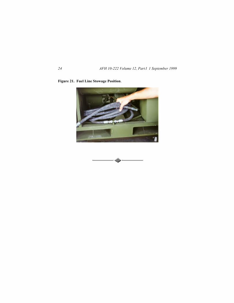
Stow fuel lines on the holder under the water vessel (figure 21).
Disconnect and remove smoke stack and drum fill adapter. Drain lines.
Thoroughly clean and dry all items then pack them in their appropriateshipping boxes.
AFH 10-222 Volume 12, Part I 1 September 199924
Figure 21. Fuel Line Stowage Position.

AFH 10-222 Volume 12, Part I 1 September 1999 25
PREWAY HEATER
Characteristics
The Preway heater (figure 22) has been in the Air Force contingency assetinventory for over 25 years attesting to its dependability and functionality. Itcan be used with either the current TEMPER tents or the older generalpurpose tents. The heater operates on diesel fuel only; use of any othertypes of fuel risks a severe fire and explosive hazard. There are severalmodels of the Preway heater; the majority are nominally rated at 70,000British thermal units (BTUs). Primary components include the following:
Fuel System. Diesel fuel is supplied to a control valve from a 5-gallon Jerrycan hung on the side of the heater unit. A siphon assembly (figure 23) is usedto flow the fuel from the can to the control valve.
Figure 22. Preway Heater.

AFH 10-222 Volume 12, Part I 1 September 199926
Figure 23. Siphon Assembly.
Combustion Chamber. The combustion chamber consists of a metal drumsurrounded by a perforated metal guard and is mounted on a metal base.
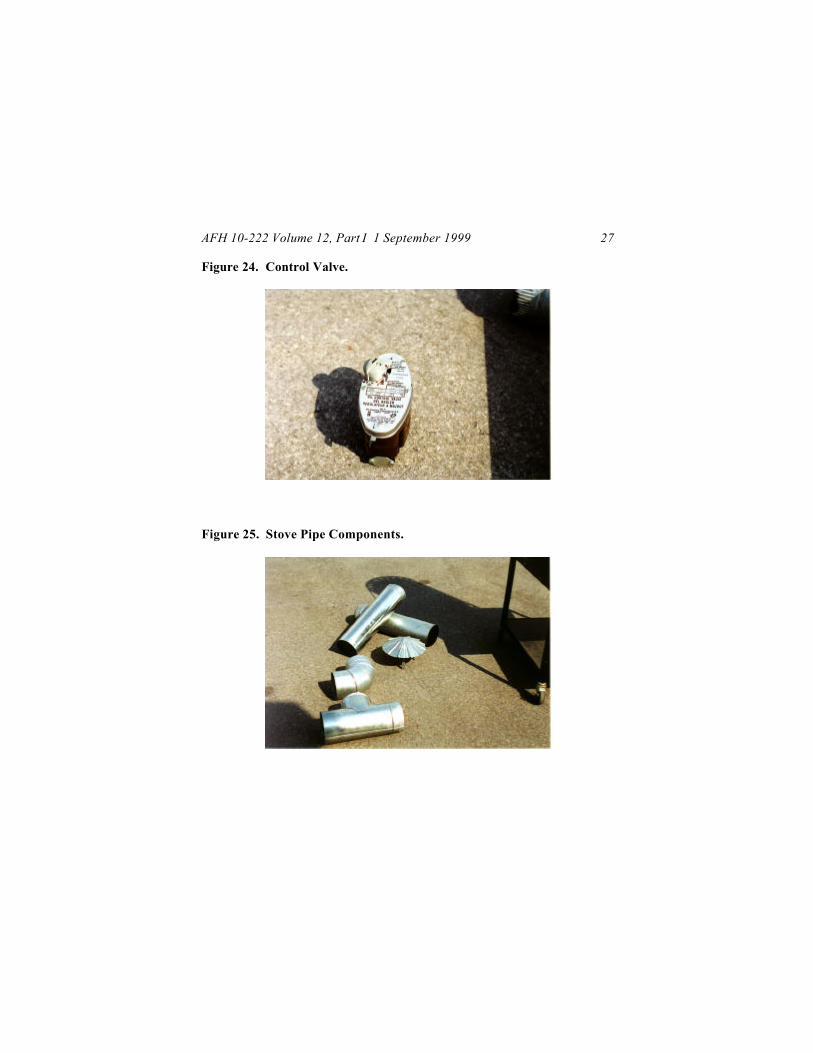
Control Valve. The control valve (figure 24) is manually adjusted to regulatefuel flow thereby raising or lowering the intensity of the flame in the heater.
Stove Pipe Components (figure 25). A draft regulator, rain cap, elbow andseveral pipe sections are included with the heater to allow venting of exhaustgas and smoke through the roof section of tents.
AFH 10-222 Volume 12, Part I 1 September 1999 27
Figure 24. Control Valve.
Figure 25. Stove Pipe Components.
AFH 10-222 Volume 12, Part I 1 September 199928
Heater Set Up
To ensure proper fuel combustion, the heater must be installed so that airflowto it is unimpeded. It must be placed on a non-combustible stove boardthat extends beyond all sides of the heater and fuel can. Locallymanufactured metal trays are often used. These stove boards must also beable to contain 5 gallons of fuel in case a fuel can ruptures or leaks severely.Maintain a separation distance of three feet between the heater and allcombustible materials. If a shield made of metal or similar non-combustiblematerial is used, separation distance can be lessened. The shield must be twoinches from any combustible material, six inches from the heater and extendbeyond the rear and sides of the fuel can. For typical tent operations, thethree-foot separation distance should not cause problems . The lower portionof the stovepipe must be kept 18 inches away from combustiblematerials. If the stovepipe is protected by sheet metal placed at least oneinch from the surface to be protected and extending the length of the pipe and12 inches beyond it on all sides, clearance may be reduced to 9 inches. Foroverall safety purposes, it is wise to have a fire extinguisher readily available.Follow the steps below for installing the heater for its most commonapplication, heating the TEMPER tent:
While the tent is in the partially erect position (see Volume 6 of thispublication series for TEMPER tent erection procedures), assemble twosections of pipe and the rain cap and insert the assembly through the stackhole in the roof of the tent. The pipe should extend about 18 inches above thetent roof. If a tent fly is being used, the pipe should extend 18 inches abovethat.
Place the heater on the stove board and locate it under the roof stove pipevent in such a way that only minor movement of the heater will be necessarywhen the full stove pipe is assembled.
Fit the elbow onto the heater flue collar and bolt in place. Center the elbowopening under the roof vent opening.

AFH 10-222 Volume 12, Part I 1 September 1999 29
Fit one length of stovepipe on the elbow and install the draft regulator tee onthis pipe. The draft regulator should face a doorway of the tent if at allpossible. Under no circumstances should the regulator face the heateritself.
Assemble the remaining sections of pipe and connect them between the draftregulator tee and the sections already in place in the tent roof section. Seefigure 26 for a picture of the finished stovepipe installation.
Figure 26. Stove Pipe Assembly.
Place a level across the top grille of the heater from front to rear and side toside. Adjust leveling bolts on the bottom of the heater until the heater is levelin both directions.
AFH 10-222 Volume 12, Part I 1 September 199930
Place a pocket level across the top of the fuel control valve from front to rearand side to side. Bend the valve bracket until valve is level.
Start Up and Operation
Check fuel can and fuel lines. Fix leaks if any are present. Smell thecontents of the fuel can to ensure that only diesel fuel is being used. Wipeoff the bottom of the fuel can so dirt doesn’t fall onto the control valve.
Hang fuel can on hook on the left side of the unit.
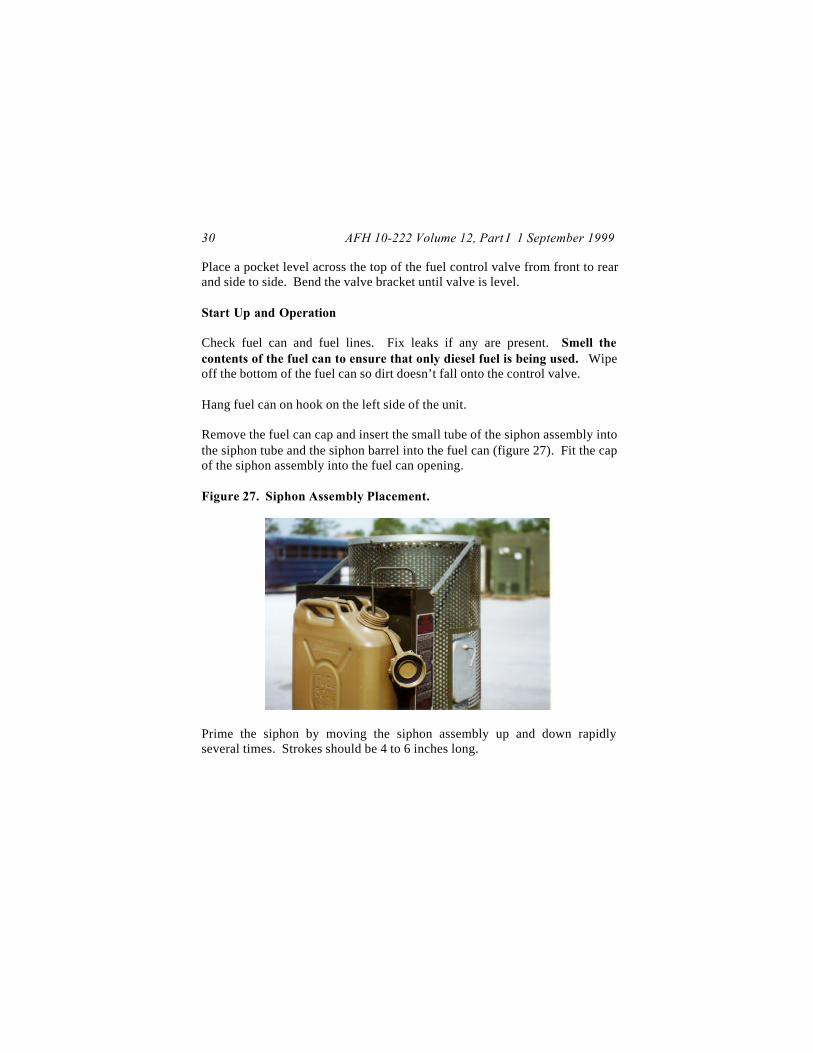
Remove the fuel can cap and insert the small tube of the siphon assembly intothe siphon tube and the siphon barrel into the fuel can (figure 27). Fit the capof the siphon assembly into the fuel can opening.
Figure 27. Siphon Assembly Placement.
Prime the siphon by moving the siphon assembly up and down rapidlyseveral times. Strokes should be 4 to 6 inches long.
AFH 10-222 Volume 12, Part I 1 September 1999 31
Set the reset lever on the fuel control valve (figure 24) in the down position(some models require reset lever to be up—see the technical order for yourunit). It’s smart to check the valve itself; often lever settings are shown onthe valve.
Turn the control knob (figure 24) to setting 6 (older units may be markedLOW and HIGH, set the knob on HIGH).
Open the burner door to visually check whether fuel has entered the burnerwell. Reset control knob to the 1 (LOW) position. Reprime if fuel has notcome into the burner within two minutes.
Light a crumpled piece of paper and drop it into the burner well. When thefuel ignites, close and latch the heater door. Let the heater operate 15minutes before regulating the flame. You can monitor the flame through thepeephole in the heater door.
Increase heat output by turning the fuel control knob counterclockwise. Turnknob one position at a time until desired flame height is obtained. Allow 10minutes between each movement of the control knob. If burner is not hotenough when the control knob is increased, the flame will be red and smokyand a roaring, vibrating noise will be heard. Turn the knob back down tosetting 1 (LOW) and start the process again making sure the 10-minute warmup periods are observed.
To decrease heat output, turn control knob clockwise to desired flame height.Do not turn the knob below setting 1 (LOW) or the flame may go out.Experience has shown that setting 4 produces the most efficient operation.Stay away from setting 1 if possible, sooting increases dramatically atthis level. Also, refrain from using setting 6, much of the heat will be lostthrough the stovepipe. Once the heater is in operation, remind people to useit properly. Do not attempt to heat food or dry clothing on the heater.
AFH 10-222 Volume 12, Part I 1 September 199932
Fuel Can Change Out
Fuel cans can be changed without the heater going out. This eliminates theneed to wait until the heater cools before re-lighting it. To do this, however,requires that you not let the can in use become empty before change out.
Turn control valve knob to setting 1 (LOW).
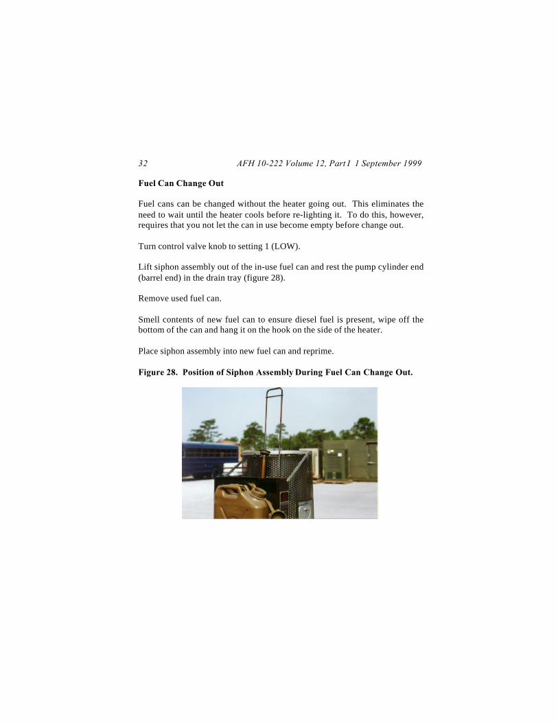
Lift siphon assembly out of the in-use fuel can and rest the pump cylinder end(barrel end) in the drain tray (figure 28).
Remove used fuel can.
Smell contents of new fuel can to ensure diesel fuel is present, wipe off thebottom of the can and hang it on the hook on the side of the heater.
Place siphon assembly into new fuel can and reprime.
Figure 28. Position of Siphon Assembly During Fuel Can Change Out.
AFH 10-222 Volume 12, Part I 1 September 1999 33
Shutdown
Turn control valve knob to setting 1 (LOW).
Set reset lever to up position to stop fuel flow (check the technical order foryour unit, some models have levers that operate differently).
Allow flame to burn out.
Reconstitution
Shutdown heater and allow it to cool.
Remove siphon assembly from heater and fuel can, drain and allow to dry. Ifavailable, clean out assembly with compressed air. Be sure to clean the littlefilter screen in the barrel end of the assembly.
Remove fuel can from heater.
Disassemble entire stovepipe and clean all items with a brush to remove soot.If a brush is not available, try using sand, silica or similar material as anexpedient cleaning abrasive.
Remove burner parts from combustion chamber and remove soot with brush.
Clean inside of combustion chamber with a brush. If available, use a vacuumto remove soot.
Drain control valve and clean the strainer filter in the control valve.
Package components in appropriate shipping/storage containers.
AFH 10-222 Volume 12, Part I 1 September 199934
ENVIRONMENTAL CONTROL UNIT
Characteristics
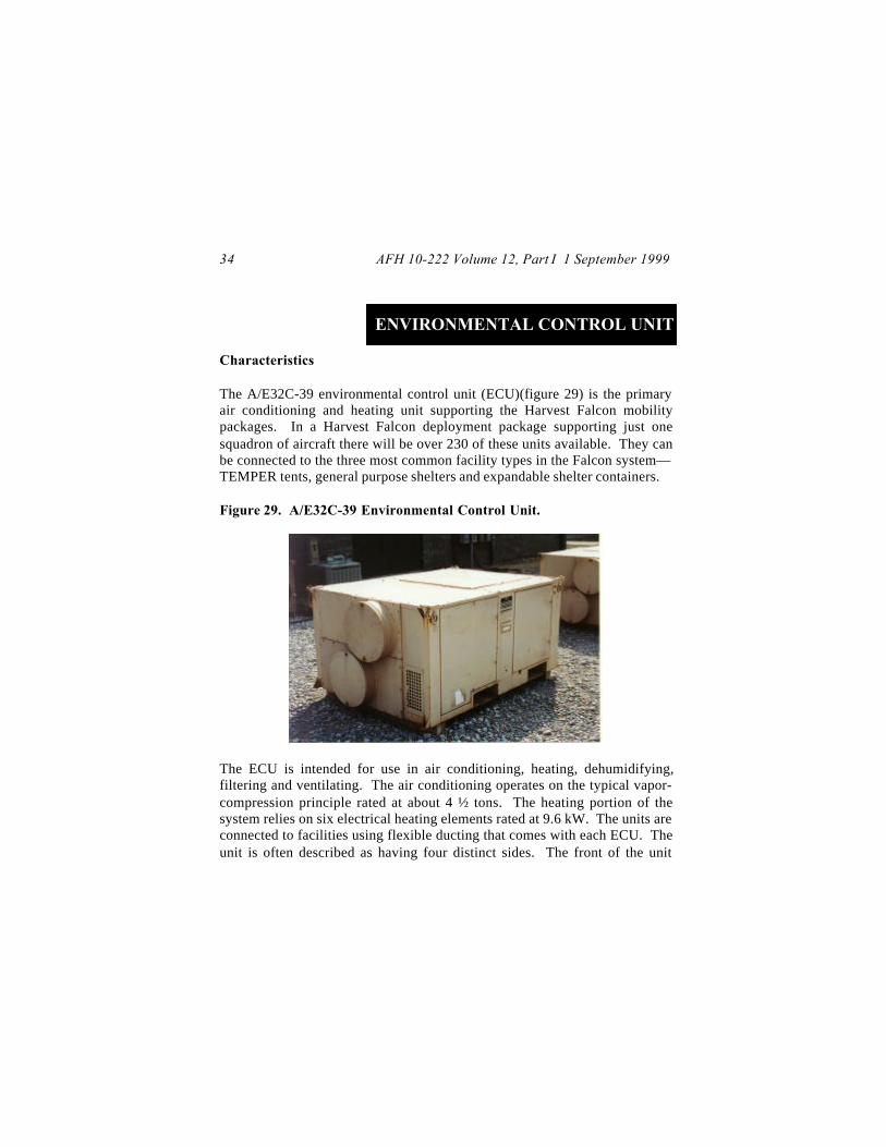
The A/E32C-39 environmental control unit (ECU)(figure 29) is the primaryair conditioning and heating unit supporting the Harvest Falcon mobilitypackages. In a Harvest Falcon deployment package supporting just onesquadron of aircraft there will be over 230 of these units available. They canbe connected to the three most common facility types in the Falcon system—TEMPER tents, general purpose shelters and expandable shelter containers.
Figure 29. A/E32C-39 Environmental Control Unit.
The ECU is intended for use in air conditioning, heating, dehumidifying,filtering and ventilating. The air conditioning operates on the typical vapor-compression principle rated at about 4 ½ tons. The heating portion of thesystem relies on six electrical heating elements rated at 9.6 kW. The units areconnected to facilities using flexible ducting that comes with each ECU. Theunit is often described as having four distinct sides. The front of the unit

AFH 10-222 Volume 12, Part I 1 September 1999 35
houses the evaporator compartment and contains the openings to which theductwork is connected. The rear of the unit contains the condensercompartment. Airflow for the condenser enters at the rear of the unit andexits through the top. The operator controls are located on the right side ofthe unit. The manufacturer’s nameplate is mounted on the left side of theunit. You will need a forklift to move and place the unit since it weighs over900 pounds. Its footprint is approximately four feet by six feet and it requires208v, 3-phase electrical power.
ECU Installation
The ECU should be placed in a relatively flat area measuring at least four feetby eight feet. There should be no more than five inches height differencebetween any of the corners . Do not place the unit in such a manner thatthe condenser fan exhaust coming from the top of the unit is obstructed.The ECU should be positioned approximately six to seven feet from thefacility it is to be connected to. The front of the unit should face the facility.Ensure you also have at least two feet of clearance at the rear of the ECUso that airflow to the condenser is not hindered. When possible, place theunit on 2 x 4 wood strips or a wood frame to keep the unit’s metal frame fromsitting in condensate. Connect the ECU to a facility as follows:
Remove the flexible ducts from their storage location in the rear of the ECU.
Remove the covers from the duct adapter flanges on the front of the unit.Store covers in the condenser compartment.
Check the lengths of the two duct pieces. The seven-foot duct is the inletduct. The nine-foot section is the discharge duct.
Clamp the inlet duct to the lower adapter flange on the unit and the lowerhole on the wall section of the facility.
AFH 10-222 Volume 12, Part I 1 September 199936
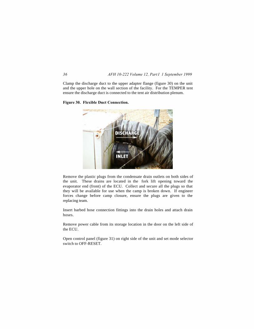
Clamp the discharge duct to the upper adapter flange (figure 30) on the unitand the upper hole on the wall section of the facility. For the TEMPER tentensure the discharge duct is connected to the tent air distribution plenum.
Figure 30. Flexible Duct Connection.
Remove the plastic plugs from the condensate drain outlets on both sides ofthe unit. These drains are located in the fork lift opening toward theevaporator end (front) of the ECU. Collect and secure all the plugs so thatthey will be available for use when the camp is broken down. If engineerforces change before camp closure, ensure the plugs are given to thereplacing team.
Insert barbed hose connection fittings into the drain holes and attach drainhoses.
Remove power cable from its storage location in the door on the left side ofthe ECU.
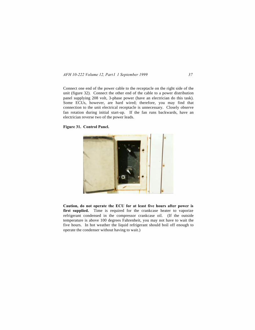
Open control panel (figure 31) on right side of the unit and set mode selectorswitch to OFF-RESET.
AFH 10-222 Volume 12, Part I 1 September 1999 37
Connect one end of the power cable to the receptacle on the right side of theunit (figure 32). Connect the other end of the cable to a power distributionpanel supplying 208 volt, 3-phase power (have an electrician do this task).Some ECUs, however, are hard wired; therefore, you may find thatconnection to the unit electrical receptacle is unnecessary. Closely observefan rotation during initial start-up. If the fan runs backwards, have anelectrician reverse two of the power leads.
Figure 31. Control Panel.
Caution, do not operate the ECU for at least five hours after power isfirst supplied. Time is required for the crankcase heater to vaporizerefrigerant condensed in the compressor crankcase oil. (If the outsidetemperature is above 100 degrees Fahrenheit, you may not have to wait thefive hours. In hot weather the liquid refrigerant should boil off enough tooperate the condenser without having to wait.)

AFH 10-222 Volume 12, Part I 1 September 199938
Figure 32. Electrical Connection Receptacle.
Operation
To ventilate a facility only, turn the mode selector switch to the VENTposition.
For cooling or heating turn the mode selector switch to AUTO. Adjust thetemperature selector control toward INCREASE or DECEASE as desired.Caution user personnel not to force the temperature selector past its stop.This breaks the switch. If the unit is not heating or cooling properly,troubleshoot the unit.
Do not operate the air conditioner in the AUTO mode when the outsidetemperature is below 50°° Fahrenheit. Instead, use the VENT mode andadmit outside makeup air. A manually operated damper (figure 33) at thefront of the unit can be opened to add fresh air to the airflow.

AFH 10-222 Volume 12, Part I 1 September 1999 39
Figure 33. Manually-Operated Damper.
To check whether the unit is cooling normally run the ECU in the AUTOmode with temperature control on full DECREASE. After 15 minutes use athermometer to check the temperature differential between the discharge andinlet ducts. If incoming air is 15° plus/minus 3° cooler than the return air, theunit is working properly.
To check whether the unit is heating normally run the ECU in the AUTOmode with temperature control on full INCREASE. After 15 minutes use athermometer to check the temperature differential between the discharge andinlet ducts. If incoming air is 13° plus/minus 3° warmer than the return air,the unit is working properly.
Shutdown and Reconstitution
Move mode selector switch to the OFF-RESET position.
Disconnect power cable from power distribution panel.
Disconnect power cable from the ECU.

AFH 10-222 Volume 12, Part I 1 September 199940
Detach ducts from the facility and the ECU.
Open the evaporator section access door of the unit and dry out any collectedcondensate.
Perform the checklist inspections called for in maintenance section of theECU technical order. Also clean the air filter and lubricate panel door hinges.
Clean exterior of unit using a cloth and cleaning solvent.
Remove, drain and dry condensate hoses. Also remove the hose connectionfittings and replace the plastic protective plugs in the condensate drain holes.
Compress and secure ducts on the duct racks (figure 34) and secure ductracks inside the condenser section.
Figure 34. Duct Storage Racks.
Coil up power cable and store it back in the condenser compartment accessdoor.

AFH 10-222 Volume 12, Part I 1 September 1999 41
Coil up condensate hoses and stow them in the condenser compartment.
Place flange covers back on the front flange adapters and seal with tape.Cover the condenser intake and outlet grilles with waterproof paper and tape.Ensure all access doors are securely closed.

AFH 10-222 Volume 12, Part I 1 September 199942
150 CUBIC FOOTREFRIGERATION UNIT
Characteristics
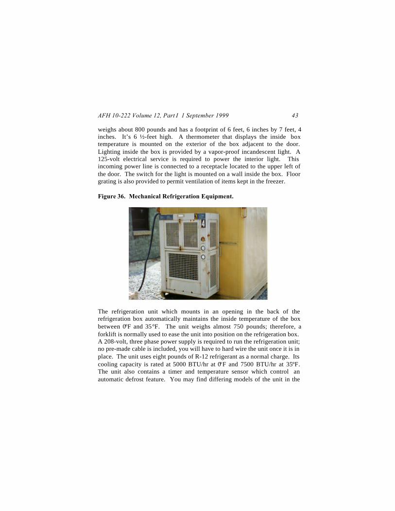
The 150 cubic foot refrigeration unit consists of two major components—thebox (figure 35) and the mechanical refrigeration equipment (figure 36).Sometimes the box and mechanical unit will be shipped already assembled.Other times the mechanical unit will be crated separately or secured insidethe refrigerator box. In such cases you will have to install the equipment onthe box on-site.
Figure 35. 150 Cubic Foot Refrigeration Box.
The refrigeration box has sheet metal walls, ceiling and floor filled withinsulating foam. It has integral lifting rings that permit movement by craneand forklift openings in its skid base enabling movement by forklift. Do notattempt to move the unit by lifting from the front or back. If the unit slipson the forks, damage could be done to the door or mechanical unit. The box
AFH 10-222 Volume 12, Part I 1 September 1999 43
weighs about 800 pounds and has a footprint of 6 feet, 6 inches by 7 feet, 4inches. It’s 6 ½-feet high. A thermometer that displays the inside boxtemperature is mounted on the exterior of the box adjacent to the door.Lighting inside the box is provided by a vapor-proof incandescent light. A125-volt electrical service is required to power the interior light. Thisincoming power line is connected to a receptacle located to the upper left ofthe door. The switch for the light is mounted on a wall inside the box. Floorgrating is also provided to permit ventilation of items kept in the freezer.
Figure 36. Mechanical Refrigeration Equipment.
The refrigeration unit which mounts in an opening in the back of therefrigeration box automatically maintains the inside temperature of the boxbetween 0°F and 35°F. The unit weighs almost 750 pounds; therefore, aforklift is normally used to ease the unit into position on the refrigeration box.A 208-volt, three phase power supply is required to run the refrigeration unit;no pre-made cable is included, you will have to hard wire the unit once it is inplace. The unit uses eight pounds of R-12 refrigerant as a normal charge. Itscooling capacity is rated at 5000 BTU/hr at 0°F and 7500 BTU/hr at 35°F.The unit also contains a timer and temperature sensor which control anautomatic defrost feature. You may find differing models of the unit in the
AFH 10-222 Volume 12, Part I 1 September 199944
field; however, their operating principles are similar. Major components ofthe refrigeration unit include:
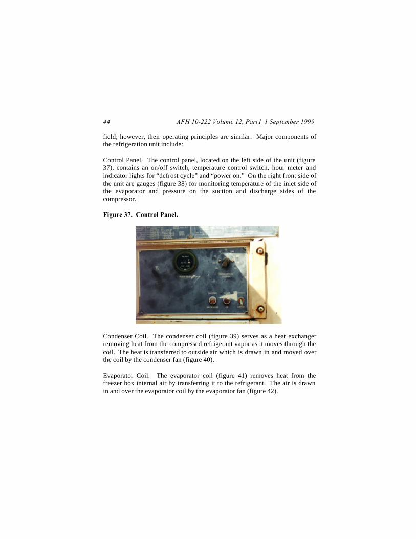
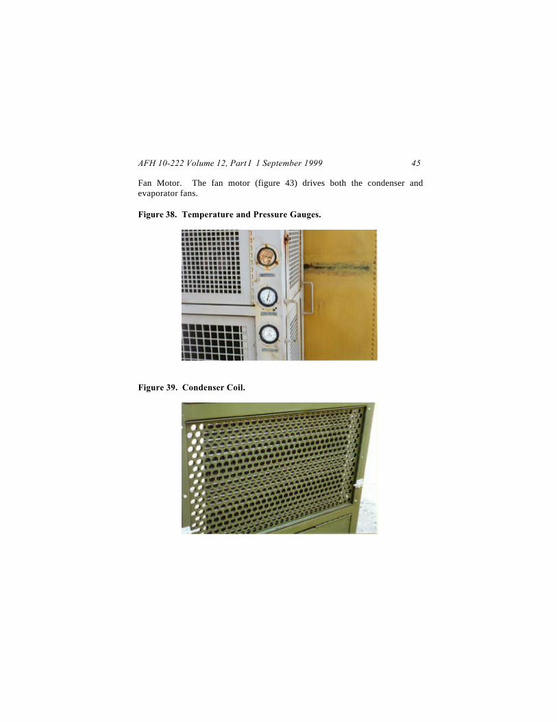
Control Panel. The control panel, located on the left side of the unit (figure37), contains an on/off switch, temperature control switch, hour meter andindicator lights for “defrost cycle” and “power on.” On the right front side ofthe unit are gauges (figure 38) for monitoring temperature of the inlet side ofthe evaporator and pressure on the suction and discharge sides of thecompressor.
Figure 37. Control Panel.
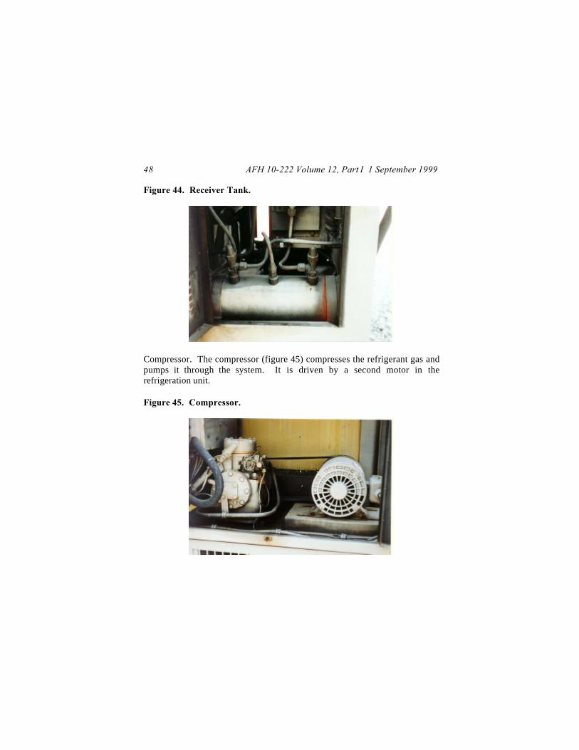
Condenser Coil. The condenser coil (figure 39) serves as a heat exchangerremoving heat from the compressed refrigerant vapor as it moves through thecoil. The heat is transferred to outside air which is drawn in and moved overthe coil by the condenser fan (figure 40).
Evaporator Coil. The evaporator coil (figure 41) removes heat from thefreezer box internal air by transferring it to the refrigerant. The air is drawnin and over the evaporator coil by the evaporator fan (figure 42).
AFH 10-222 Volume 12, Part I 1 September 1999 45
Fan Motor. The fan motor (figure 43) drives both the condenser andevaporator fans.
Figure 38. Temperature and Pressure Gauges.
Figure 39. Condenser Coil.

AFH 10-222 Volume 12, Part I 1 September 199946
Figure 40. Condenser Fan.
Figure 41. Evaporator Coil.

AFH 10-222 Volume 12, Part I 1 September 1999 47
Figure 42. Evaporator Fan.
Figure 43. Fan Motor.
Receiver Tank. The receiver tank (figure 44) collects and stores liquidrefrigerant.
AFH 10-222 Volume 12, Part I 1 September 199948
Figure 44. Receiver Tank.
Compressor. The compressor (figure 45) compresses the refrigerant gas andpumps it through the system. It is driven by a second motor in therefrigeration unit.
Figure 45. Compressor.
AFH 10-222 Volume 12, Part I 1 September 1999 49
150 Cubic Foot Refrigeration Unit Set Up and Pre-OperationPreparation
The refrigeration box must be placed on a flat, level surface. A paved area orconcrete pad is preferred but firm ground may also be used providing it cansupport footprint pressures of 250 psi. Shaded areas are desirable such as treecover, open sheds or even camouflage netting. Shading improves theefficiency of the unit. Also critical is the need to provide open air spacearound the mechanical unit once it is installed in the box. A minimum of 3feet of clear space is required in the front of and to both sides of thecondenser portion of the refrigeration unit. Do not locate the box in anarea subject to smoke or blowing dirt if at all possible. These contaminantscan foul the air intake area of the condenser. Lastly, remember you musthave a 208 volt, three-phase, power source nearby--avoid long power cableruns and the associated voltage drop. Once you have checked therefrigeration box for serviceability and sited it in a suitable location, installthe refrigeration unit in the box as follows:
Remove the refrigeration unit from its shipping box and inspect it for anyshipping damage. Pay close attention to the condition of the gasket seal(figure 46) on the back of the condenser section.
Check the wall surface around the panel opening in the back of therefrigeration box to ensure there are no irregularities.
Carefully guide the evaporator section of the refrigeration unit into theopening. If available, use a forklift for this task.
Slide the unit back until the gasket seal is uniformly in contact with the wallsurface. This may take some adjustment but stick with it—a uniform seal isnecessary for proper freezer operation.
From the inside of the unit slide the mounting bolts through the holes in thebox wall and metal frame of the refrigeration unit.

AFH 10-222 Volume 12, Part I 1 September 199950
Figure 46. Condenser Section Gasket Seal.
Uniformly tighten the nuts on all four mounting bolts by turning each nut afew times in rotation around the metal frame. Tighten the nuts until you havemaximum compression of the gasket seal.
With the refrigeration unit now installed in the refrigeration box, there areseveral additional steps that must be accomplished prior to allowing the unitto be placed into full operation. These include setting valves and the defrosttimer, adjusting belts and connecting power.
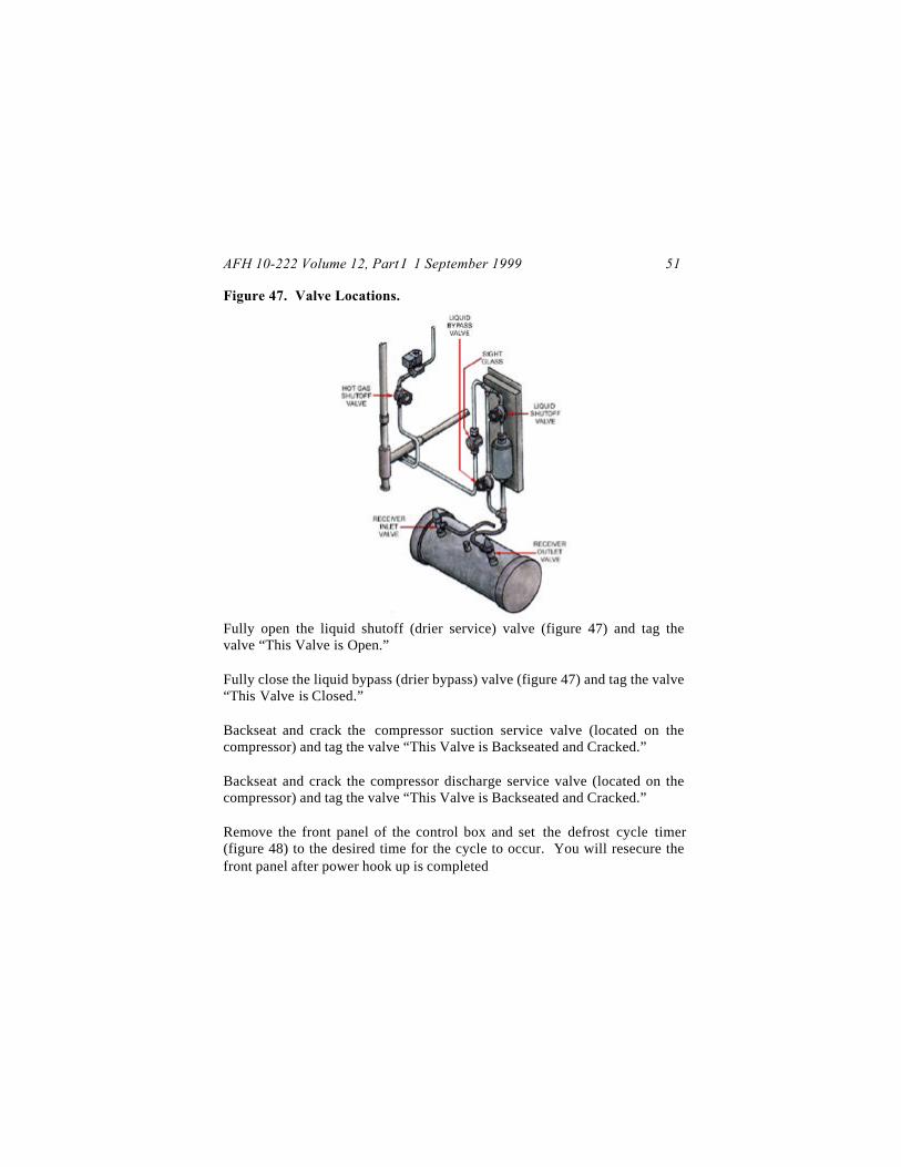
Fully open the receiver inlet valve (figure 47) and tag the valve “This Valveis Open.”
Fully open the receiver outlet valve (figure 47) and tag the valve “This Valveis Open.”
Fully open the hot gas shut off valve (figure 47) and tag the valve “ThisValve is Open.”
AFH 10-222 Volume 12, Part I 1 September 1999 51
Figure 47. Valve Locations.
Fully open the liquid shutoff (drier service) valve (figure 47) and tag thevalve “This Valve is Open.”
Fully close the liquid bypass (drier bypass) valve (figure 47) and tag the valve“This Valve is Closed.”
Backseat and crack the compressor suction service valve (located on thecompressor) and tag the valve “This Valve is Backseated and Cracked.”
Backseat and crack the compressor discharge service valve (located on thecompressor) and tag the valve “This Valve is Backseated and Cracked.”
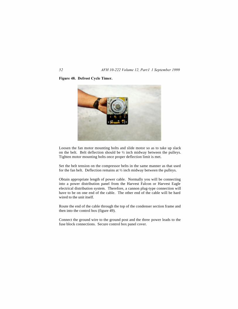
Remove the front panel of the control box and set the defrost cycle timer(figure 48) to the desired time for the cycle to occur. You will resecure thefront panel after power hook up is completed
AFH 10-222 Volume 12, Part I 1 September 199952
Figure 48. Defrost Cycle Timer.
Loosen the fan motor mounting bolts and slide motor so as to take up slackon the belt. Belt deflection should be ½ inch midway between the pulleys.Tighten motor mounting bolts once proper deflection limit is met.
Set the belt tension on the compressor belts in the same manner as that usedfor the fan belt. Deflection remains at ½ inch midway between the pulleys.
Obtain appropriate length of power cable. Normally you will be connectinginto a power distribution panel from the Harvest Falcon or Harvest Eagleelectrical distribution system. Therefore, a cannon plug-type connection willhave to be on one end of the cable. The other end of the cable will be hardwired to the unit itself.
Route the end of the cable through the top of the condenser section frame andthen into the control box (figure 49).
Connect the ground wire to the ground post and the three power leads to thefuse block connections. Secure control box panel cover.

AFH 10-222 Volume 12, Part I 1 September 1999 53
Figure 49. Cable Routing.
Turn on power at the power distribution panel. Turn unit on and checkrotation of motors. If motors are not turning clockwise, turn off power,reopen the control box and reverse two of the power leads (a three-phasemotor must have the phases properly connected to operate and run in theproper direction).
Connect a second power cable between the power distribution panel and thereceptacle on the front of the refrigeration box. This is a single phase,125volt line.
Set the thermostat on the control box front panel to the desired temperature.
Operation
To operate the refrigeration unit, place the REFRIGERATOR ON-OFFswitch on the control box to the ON position. The unit will start, stop anddefrost automatically while maintaining the desired temperature as set on thethermostat. Prior to turning on the unit, however, make one last inspection of
AFH 10-222 Volume 12, Part I 1 September 199954
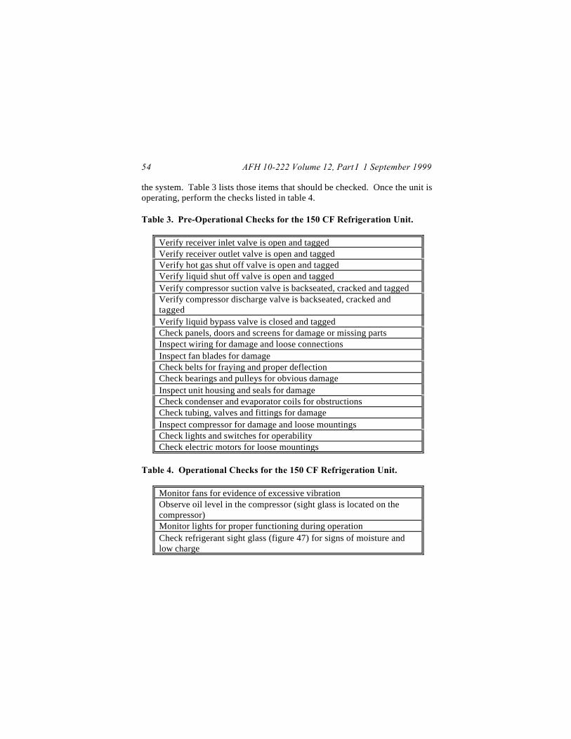
the system. Table 3 lists those items that should be checked. Once the unit isoperating, perform the checks listed in table 4.
Table 3. Pre-Operational Checks for the 150 CF Refrigeration Unit.
Verify receiver inlet valve is open and taggedVerify receiver outlet valve is open and taggedVerify hot gas shut off valve is open and taggedVerify liquid shut off valve is open and taggedVerify compressor suction valve is backseated, cracked and taggedVerify compressor discharge valve is backseated, cracked andtaggedVerify liquid bypass valve is closed and taggedCheck panels, doors and screens for damage or missing partsInspect wiring for damage and loose connectionsInspect fan blades for damageCheck belts for fraying and proper deflectionCheck bearings and pulleys for obvious damageInspect unit housing and seals for damageCheck condenser and evaporator coils for obstructionsCheck tubing, valves and fittings for damageInspect compressor for damage and loose mountingsCheck lights and switches for operabilityCheck electric motors for loose mountings
Table 4. Operational Checks for the 150 CF Refrigeration Unit.
Monitor fans for evidence of excessive vibrationObserve oil level in the compressor (sight glass is located on thecompressor)Monitor lights for proper functioning during operationCheck refrigerant sight glass (figure 47) for signs of moisture andlow charge
AFH 10-222 Volume 12, Part I 1 September 1999 55
Shutdown and Reconstitution
To shutdown the unit, turn the REFRIGERATOR ON-OFF switch on thecontrol box to the OFF position.
Empty the refrigeration box completely.
Pump down the refrigeration unit—see technical order for details.
Shut off power and disconnect cable from the control box and facilitydistribution panel.
Loosen the compressor and fan drive belts.
Clean and dry the refrigeration unit. Touch-up paint any exposed surfaces.
Unbolt the unit from the refrigeration box wall and remove unit, if required.
Crate refrigeration unit.
Install closure plug assembly in the back wall of the refrigeration box.
Wash and dry the interior and exterior of the box.
Ensure the vapor proof internal light is secure.
Close box door and secure with padlock; attach keys to padlock.
AFH 10-222 Volume 12, Part I 1 September 199956
1200 CUBIC FOOTREFRIGERATION UNIT
Characteristics
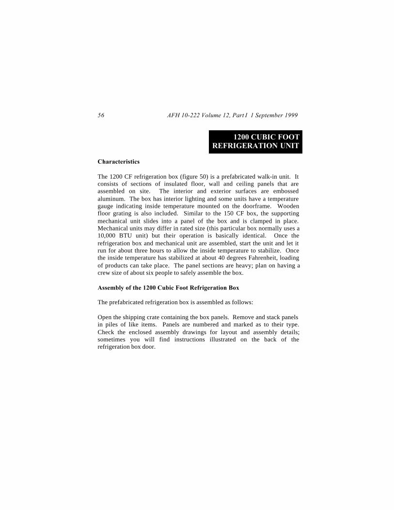
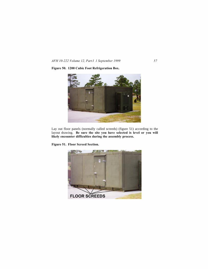
The 1200 CF refrigeration box (figure 50) is a prefabricated walk-in unit. Itconsists of sections of insulated floor, wall and ceiling panels that areassembled on site. The interior and exterior surfaces are embossedaluminum. The box has interior lighting and some units have a temperaturegauge indicating inside temperature mounted on the doorframe. Woodenfloor grating is also included. Similar to the 150 CF box, the supportingmechanical unit slides into a panel of the box and is clamped in place.Mechanical units may differ in rated size (this particular box normally uses a10,000 BTU unit) but their operation is basically identical. Once therefrigeration box and mechanical unit are assembled, start the unit and let itrun for about three hours to allow the inside temperature to stabilize. Oncethe inside temperature has stabilized at about 40 degrees Fahrenheit, loadingof products can take place. The panel sections are heavy; plan on having acrew size of about six people to safely assemble the box.
Assembly of the 1200 Cubic Foot Refrigeration Box
The prefabricated refrigeration box is assembled as follows:
Open the shipping crate containing the box panels. Remove and stack panelsin piles of like items. Panels are numbered and marked as to their type.Check the enclosed assembly drawings for layout and assembly details;sometimes you will find instructions illustrated on the back of therefrigeration box door.
AFH 10-222 Volume 12, Part I 1 September 1999 57
Figure 50. 1200 Cubic Foot Refrigeration Box.
Lay out floor panels (normally called screeds) (figure 51) according to thelayout drawing. Be sure the site you have selected is level or you willlikely encounter difficulties during the assembly process.
Figure 51. Floor Screed Section.

AFH 10-222 Volume 12, Part I 1 September 199958
Secure floor screeds together using the built-in locking mechanisms (figure52) and apply a sealer between all the screed joints. For short-termoperations (say less than 30 days), duct tape will work; for longer termoperations, use a silicon sealer.
Figure 52. Floor, Wall and Ceiling Locking Mechanisms.
Set one of the vertical corner panels (figure 53) in place on the floor screeds.Be sure the number of the corner panel matches the number shown on theassembly drawings.
Place one of the vertical wall panels (figure 53) adjacent to the corner paneland fasten the two panels together. Turning the locking mechanisms one-quarter turn clockwise does this. Do not turn the locking mechanisms anyfurther; you will tighten them further later when you fully lock all the panelstogether.
Continue connecting wall and corner panels together until the entire box isbuilt.
AFH 10-222 Volume 12, Part I 1 September 1999 59
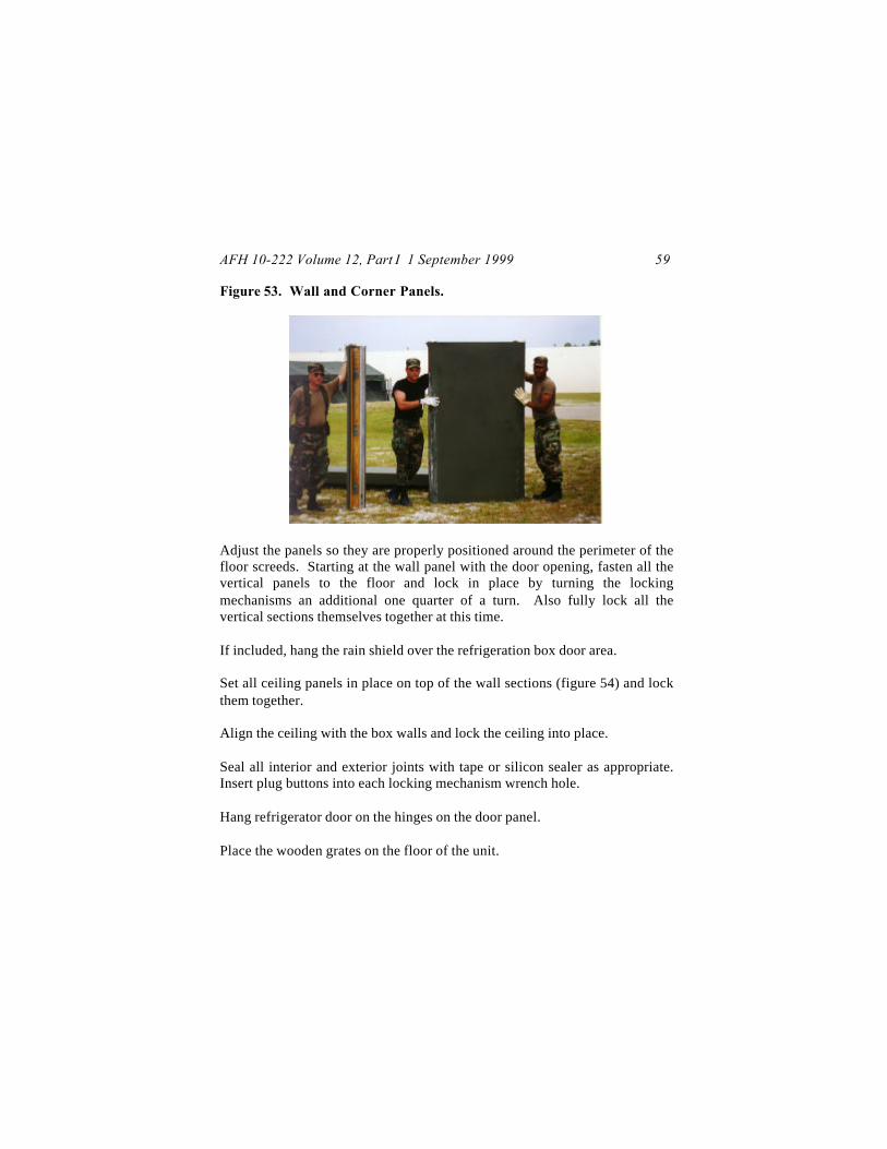
Figure 53. Wall and Corner Panels.
Adjust the panels so they are properly positioned around the perimeter of thefloor screeds. Starting at the wall panel with the door opening, fasten all thevertical panels to the floor and lock in place by turning the lockingmechanisms an additional one quarter of a turn. Also fully lock all thevertical sections themselves together at this time.
If included, hang the rain shield over the refrigeration box door area.
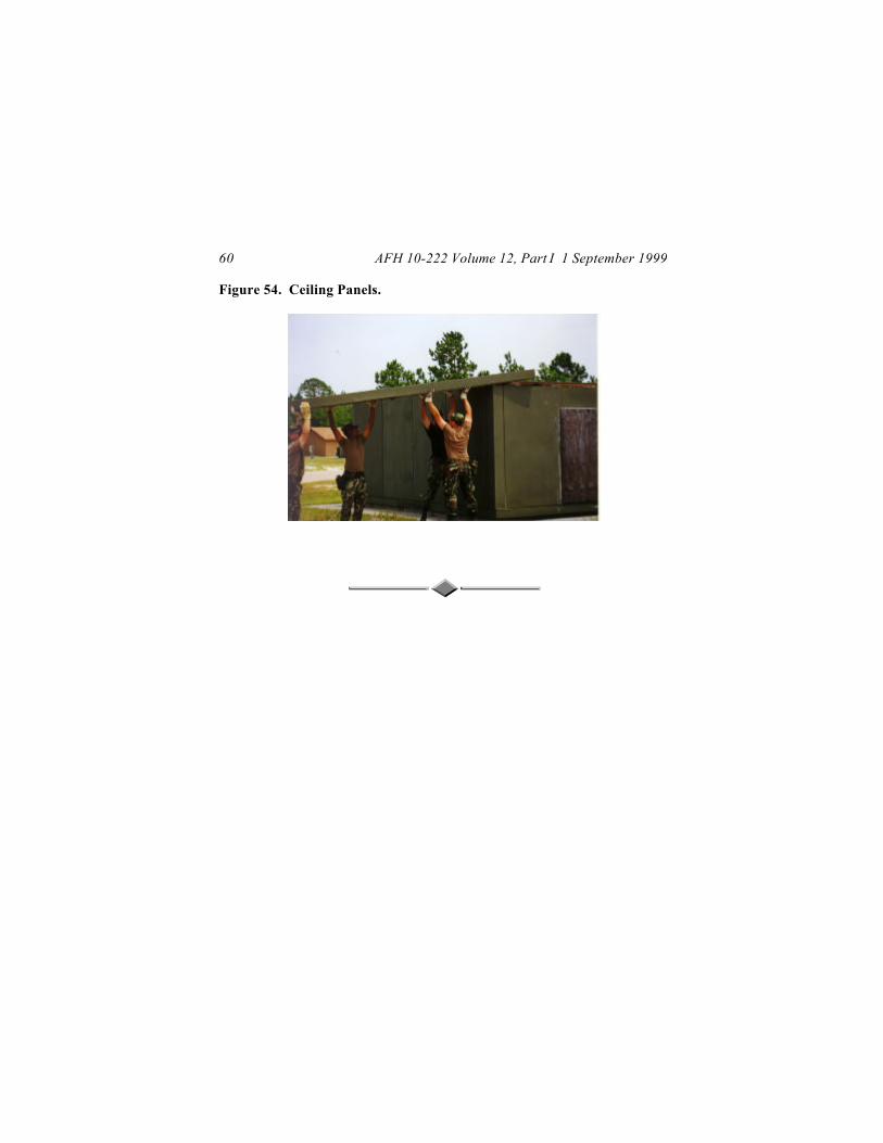
Set all ceiling panels in place on top of the wall sections (figure 54) and lockthem together.
Align the ceiling with the box walls and lock the ceiling into place.
Seal all interior and exterior joints with tape or silicon sealer as appropriate.Insert plug buttons into each locking mechanism wrench hole.
Hang refrigerator door on the hinges on the door panel.
Place the wooden grates on the floor of the unit.
AFH 10-222 Volume 12, Part I 1 September 199960
Figure 54. Ceiling Panels.

AFH 10-222 Volume 12, Part I 1 September 1999 61
MOBILE WATER CHILLER
Characteristics
The mobile water chiller (figure 55) is used to provide chilled water topersonnel normally working at remote locations throughout the base. It isusually attached to a 400-gallon water trailer for mobility purposes, but canalso support small stationary fabric tanks. The chiller is capable of cooling120°F intake water down to about 60°F at a rate of 40-gallons per hour. Therefrigeration system and water pump are driven by an air-cooled, gasoline-powered engine. The engine can be started using a 12-volt power source ormanually started using a pull rope. Weighing 315 pounds, the chiller is 34inches long, 26 inches wide and 24 inches high. The refrigeration system onthe unit requires 3.75 pounds of R-12 refrigerant for a full charge.
Figure 55. Mobile Water Chiller.
AFH 10-222 Volume 12, Part I 1 September 199962
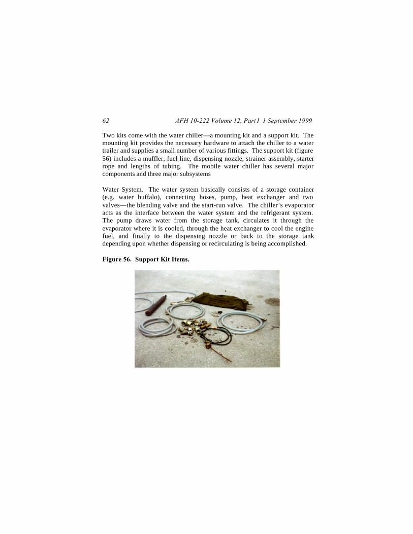
Two kits come with the water chiller—a mounting kit and a support kit. Themounting kit provides the necessary hardware to attach the chiller to a watertrailer and supplies a small number of various fittings. The support kit (figure56) includes a muffler, fuel line, dispensing nozzle, strainer assembly, starterrope and lengths of tubing. The mobile water chiller has several majorcomponents and three major subsystems
Water System. The water system basically consists of a storage container(e.g. water buffalo), connecting hoses, pump, heat exchanger and twovalves—the blending valve and the start-run valve. The chiller’s evaporatoracts as the interface between the water system and the refrigerant system.The pump draws water from the storage tank, circulates it through theevaporator where it is cooled, through the heat exchanger to cool the enginefuel, and finally to the dispensing nozzle or back to the storage tankdepending upon whether dispensing or recirculating is being accomplished.
Figure 56. Support Kit Items.

AFH 10-222 Volume 12, Part I 1 September 1999 63
Refrigerant System. The major parts of the refrigerant system include thecompressor, condenser coil, condenser fan and evaporator. The compressedR-12 refrigerant passes through the condenser where it is liquefied. Heatfrom this process is dissipated by the condenser fan blowing over thecondenser coil. The liquid refrigerant then passes through the evaporatorwhere it picks up heat from the water in the water system and then flows backto the compressor.
Power System. The power system is basically an internal combustion engine.The engine is controlled by pressure and temperature switches that will shutdown the operation of the engine if water fails to flow or is cooledsufficiently, or pressure problems develop in the refrigerant system.
Water Chiller Set Up
Set up of the mobile water chiller is a relatively straightforward process.Perform the following steps:
Open the top door of the chiller and attach the exhaust pipe to the engineexhaust port.
Remove shipping plugs from water line connections marked COOLRECIRCULATE, COOL DISPENSE and WARM IN (figure 57). Make surethere are no dirt particles or foreign objects in the openings.
Install three of the hoses from the support kit to the openings on the chiller(figure 58). Connect the free end of the WARM IN hose to the strainerassembly. The arrow on the strainer assembly should point toward thechiller; this arrow denotes the direction of flow. Connect one end of thefourth hose to the other end of the strainer assembly and the other end of thefourth hose to the water source.

AFH 10-222 Volume 12, Part I 1 September 199964
Figure 57. Chiller Hose Connections Points.
Figure 58. Hose Connections.
AFH 10-222 Volume 12, Part I 1 September 1999 65
Route the free end of the COOL RECIRCULATE hose back to the watersource.
Attach the dispensing nozzle to the free end of the COOL DISPENSE hose(figure 58).
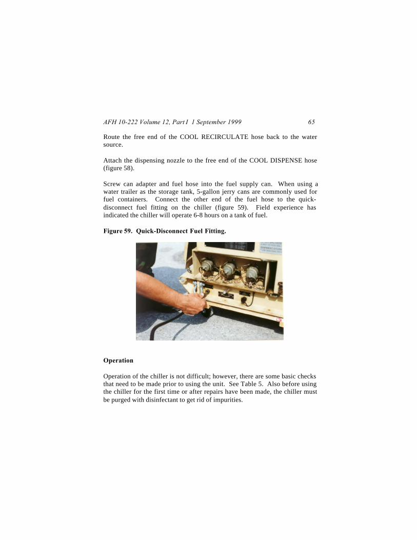
Screw can adapter and fuel hose into the fuel supply can. When using awater trailer as the storage tank, 5-gallon jerry cans are commonly used forfuel containers. Connect the other end of the fuel hose to the quick-disconnect fuel fitting on the chiller (figure 59). Field experience hasindicated the chiller will operate 6-8 hours on a tank of fuel.
Figure 59. Quick-Disconnect Fuel Fitting.
Operation
Operation of the chiller is not difficult; however, there are some basic checksthat need to be made prior to using the unit. See Table 5. Also before usingthe chiller for the first time or after repairs have been made, the chiller mustbe purged with disinfectant to get rid of impurities.
AFH 10-222 Volume 12, Part I 1 September 199966
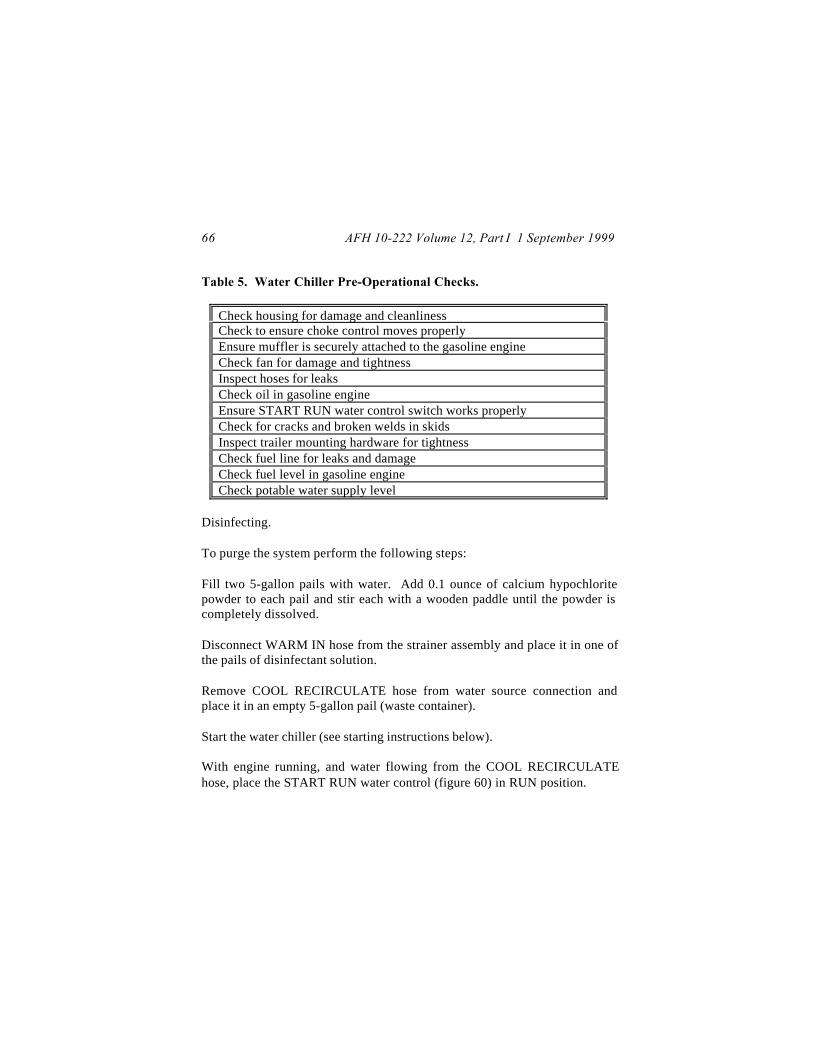
Table 5. Water Chiller Pre-Operational Checks.
Check housing for damage and cleanlinessCheck to ensure choke control moves properlyEnsure muffler is securely attached to the gasoline engineCheck fan for damage and tightnessInspect hoses for leaksCheck oil in gasoline engineEnsure START RUN water control switch works properlyCheck for cracks and broken welds in skidsInspect trailer mounting hardware for tightnessCheck fuel line for leaks and damageCheck fuel level in gasoline engineCheck potable water supply level
Disinfecting.
To purge the system perform the following steps:
Fill two 5-gallon pails with water. Add 0.1 ounce of calcium hypochloritepowder to each pail and stir each with a wooden paddle until the powder iscompletely dissolved.
Disconnect WARM IN hose from the strainer assembly and place it in one ofthe pails of disinfectant solution.
Remove COOL RECIRCULATE hose from water source connection andplace it in an empty 5-gallon pail (waste container).
Start the water chiller (see starting instructions below).
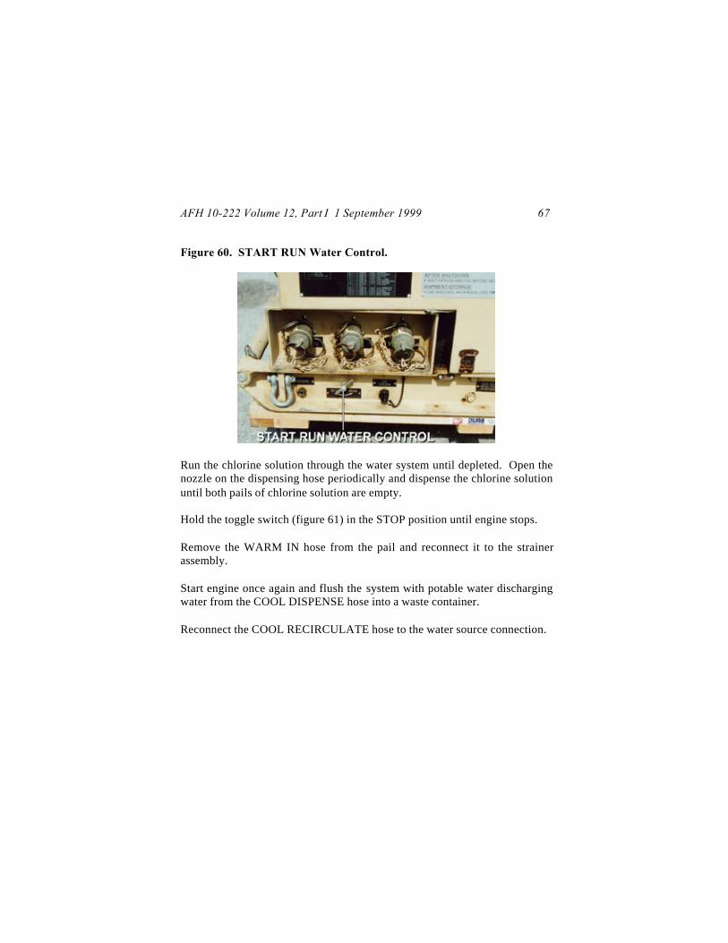
With engine running, and water flowing from the COOL RECIRCULATEhose, place the START RUN water control (figure 60) in RUN position.
AFH 10-222 Volume 12, Part I 1 September 1999 67
Figure 60. START RUN Water Control.
Run the chlorine solution through the water system until depleted. Open thenozzle on the dispensing hose periodically and dispense the chlorine solutionuntil both pails of chlorine solution are empty.
Hold the toggle switch (figure 61) in the STOP position until engine stops.
Remove the WARM IN hose from the pail and reconnect it to the strainerassembly.
Start engine once again and flush the system with potable water dischargingwater from the COOL DISPENSE hose into a waste container.
Reconnect the COOL RECIRCULATE hose to the water source connection.

AFH 10-222 Volume 12, Part I 1 September 199968
Figure 61. Toggle Switch, Choke, Pneumatic Timer Switch, and StarterButton.
Startup.
Once the chiller has been disinfected, start up for normal operations can beaccomplished. Perform the following steps:
Place START RUN water control in START position.
Open end door and pull out choke (figure 61) on gasoline engine. Onceengine is running steadily choke can be pushed back in.
Pump bulb in fuel line until pressure is felt.
Wrap starter rope around flywheel pulley. Push pneumatic timer switch(figure 61) and pull rope to start the engine.

AFH 10-222 Volume 12, Part I 1 September 1999 69
The chiller can also be started using a 12-volt power source. Plug the powersource cable into the 12 VOLT INPUT FOR STARTING connection (figure62).
Hold the toggle switch (figure 61) in the START position and push the starterbutton (figure 61) to start engine.
Open dispenser nozzle. When there are few or no air bubbles in the watercoming from the hose, place the START RUN water control in the RUNposition.
If the 12–volt source was used, disconnect the power cable once the enginehas started.
Chiller will operate until water in the storage tank is sufficiently cooled ortank is emptied. When either of these conditions are reached, the chiller willautomatically shut down.
Figure 62. 12 VOLT INPUT FOR STARTING Connection.

AFH 10-222 Volume 12, Part I 1 September 199970
Once the chiller is operating there are several items that should be monitored.These are highlighted in table 6.
Table 6. Operational Checks for the Water Chiller.
Check grilles for dirt and debrisMonitor muffler for tightness and exhaust leaksInspect hoses for leaks and chafingCheck sight glass (next to power connection) for clear, bubble-freerefrigerantMonitor fuel levelMonitor water supply level
Shutdown and Reconstitution
Shutdown of the chiller is accomplished by holding the toggle switch in theSTOP position until the engine stops. The START RUN water control is thenplaced in the START position.
To reconstitute the unit perform the above shutdown procedures plus thefollowing steps:
Spray the kit bags with insecticide prior to storing components.
Allow the muffler to cool, disconnect it from the chiller and put it in thesupport kit bag.
Close and latch the top and side doors.
Disconnect fuel hose from water chiller and fuel supply container. Drain thehose and place in kit bag after it is dry.
Disconnect and drain all water hoses. Place hoses in kit bag when dry.
AFH 10-222 Volume 12, Part I 1 September 1999 71
Drain and dry strainer assembly and nozzle. Place in kit bag when dry.
Install shipping plugs in hose connection points on chiller.
JOHN W. HANDY, Lt General, USAFDCS/Installations & Logistics