guide to grouting with silica sol – for sealing in hard
TRANSCRIPT

BeFo Report 118
GUIDE TO GROUTING WITH SILICA SOL– for sealing in hard rock
Johan Funehag
Box 5501SE-114 85 Stockholm
[email protected] • www.befoonline.org ISSN 1104-1773Visiting address: Storgatan 19
118
Silica SolSalt

Cover illustration: Karin Holmgren, Chalmers University of Technology

STIFTELSEN BERGTEKNISK FORSKNING ROCK ENGINEERING RESEARCH FOUNDATION
GUIDE TO GROUTING WITH SILICA SOL - for sealing in hard rock
Handledning för injektering med silica sol - för tätning i hårt berg Johan Funehag Tyréns AB Chalmers University of Technology
BeFo Report 118 Stockholm 2012 ISSN 1104 – 1773 ISRN BEFO-R—118—SE


In memory of Professor Gunnar Gustafson This guide is founded on, and a result of, the driving force of an incredible person and his capacity to understand problems. Gunnar Gustafson had a rare entrepreneurial spirit that allowed us to constantly reach out and apply the results of our research. His death is a great source of sorrow for the industry but his energy and inspiration will remain within us for a long time to come.


BeFo Report 118
i
Foreword
Grouting research has been part of the BeFo programme for 30 years and is an important part of Scandinavian rock construction. Carefully executed grouting is a cheaper alternative to sealed lining. Stricter stipulations regarding low ingression levels are pushing up the cost of grouting, making cost calculation more difficult. Grouting largely takes place in conjunction with rock extraction. The lifespan of the grout is affected by the groundwater, possible stress movements, the materials used and the design that is adopted. Many of these factors can be influenced and there is a demand for greater predictability and a better financial outcome for grouting. Grout that fails to harden or flows back could result in erosion of the grout and deterioration in the quality of the work. Strength is linked to groundwater pressure and fan geometry in the grouting design. The threshold for how watertight the rock can be made without lining is being raised constantly. Research in recent years has led to a new type of grout, silica sol, which when used correctly offers excellent functionality. It was introduced onto the Swedish market as a grout for hard rock in 2002 and since then it has been used in several tunnels. The grout is suitable as a complement to traditional cement grouting in order to meet strict water ingression stipulations in tunnels. The aim of this current project is to provide a guide to grouting with silica sol. The guide is aimed at contractors, consultants and clients. The purpose is threefold: to provide a de-sign and implementation tool for industry, to address the problems that could arise and to pre-sent measures that can be taken to rectify such problems. The guide summarises the research that has been conducted in this area, in particular at Chalmers University of Technology, as well as the projects in which the University has been involved.
The reference group that contributed to the project comprised Gunnar Gustafson, Chalmers University of Technology, Bjarne Liljestrand, STRABAG, Magnus Zetterlund, Vattenfall, Ken-neth Rosell, Swedish Transport Administration, Hans-Olov Hognestad, BASF, Inger Jansson, Eka, and Mikael Hellsten, BeFo.
Stockholm, October 2012
Per Tengborg
BeFo Report 118
ii
Sammanfattning
Föreliggande rapport är en redogörelse av kunskapsläget vid dags datum i hur man bör injektera med silica sol i hårt berg. Den innefattar både resultatet av flera teoretiska studier samt erfaren-heter från ett antal genomförda projekt där silica sol använts som injekteringsmedel. Rapporten kan ses som en handledning ämnad för beställare, konsulter and entreprenörer i hur man utför en silica sol injektering. Den beskriver projekteringstegen, utförandet samt hur styrning på plats görs. En del som tidigare inte rapporterats så ofta är de problem som kan uppstå vid en injekte-ring and är i denna rapport framlyfta för att åskådliggöra vilka val entreprenören måste göra.
På senare tid har kraven på täthet vid tunnelbyggande skärpts väsentligt. De täthetskrav som ställs, ibland mindre än någon liter per minut and 100 meter tunnel, samt beställarens egna funktionskrav på dropp and dylikt har medfört att konventionell förinjektering med cementbase-rade injekteringsmedel kan bli otillräcklig. Om en hydraulisk sprickvidd ner till ex 30 µm måste tätas innebär detta att ett annat injekteringsmedel än cement behöver användas alternativt kom-pletteras.
Ett miljömässigt bra alternativt injekteringsmedel som klarar de högre täthetskraven jämfört med de traditionella cementbaserade injekteringsmedlen är kolloidalt kisel, dvs. silica sol. Silica sol är en kolloidal lösning av silikapartiklar i vatten. När silica sol blandas med exempelvis van-ligt koksalt startar en reaktion and partiklarna bildar bindningar mellan sig. Silica sol har ett helt annat beteende jämfört med cement. Forskningen har, liksom för konventionell cementinjekte-ring, visat att sprickvidden, injekteringstrycket and tiden har stor inverkan på injekteringsresul-tatet men för silica solen har dessutom geltiden stor betydelse för utförandet and resultatet. De praktiska fördelarna med silica sol, förutom inträngningsförmågan, är uppenbara när det kom-mer till att styra injekteringsmedlets geltid. Med silica sol kan geltiden styras and därmed injek-teringstiden per hål från några minuter till flera timmar, om så är önskvärt.
Den styrbara and snabba viskositetstillväxten kopplas till inträngningslängden via den hydrau-liska sprickvidden, injekteringsövertryck and geltid på silica solen. Med vetskap om vilken minsta sprickvidd som behöver tätas för att klara inläckagekravet kan en härledbar injekterings-design upprättas där den använda injekteringstiden kan förutsägas.
För att injekteringen skall bli så effektiv som möjligt bör utrustning and genomförande anpas-sas. I de hittills genomförda projekten har en traditionell cementinjekteringsutrustning använts med framgång. De problem som observerats under en silica sol injektering beror på stora injek-teringsvolymer, återslag eller ytläckage. När sådana problem uppstår måste designen uppdate-ras. Denna handledning ger förslag till sådana uppdateringar, i huvudsak bestående av föränd-ringar i tryck eller geltid.
Nyckelord: Design, handledning, berg, tunnel, injektering, silica sol

BeFo Report 118
iii
Summary
This report is a summary of current knowledge of how grouting in hard rock with silica sol should be performed. It includes results from several theoretical studies and experience from different tunnel projects where silica sol has been used. The report can be regarded as a guide for clients, consultants and contractors to what silica sol grouting means in practice. It describes the design stages and execution and how the work can be directed and controlled on site. Prob-lems encountered during grouting is an area that has not been particularly well reported in the past. These problems are highlighted in this report to show all the choices the contractor needs to make.
In recent decades, the stipulations regarding ingression of water into tunnels have become strict-er. The stipulations, sometimes less than one litre per minute per hundred metres of tunnel, to-gether with the client's demands regarding functionality for the permitted number of drips, have meant that at times traditional cement grouting has not been adequate. If, for instance, a hydrau-lic aperture of a fracture down to 30 µm needs to be sealed to meet the stipulations, a grout oth-er than a cement grout needs to be used or used as a supplement.
An environmentally sound alternative that meets the strict stipulations regarding water ingres-sion is colloidal silica, i.e. silica sol. Silica sol is a colloidal mixture of silica particles in water. When silica sol is mixed with, for instance, ordinary table salt (sodium chloride, NaCl) a reac-tion starts and bonding between the particles commences. Silica sol behaves in a totally differ-ent way to cement grouts. Research has shown – as is also the case for cement grouting – that the fracture aperture, the grouting pressure and grouting time all have a specific role to play in the grouting result. In addition, the gel time for silica sol has an impact on both the execution and result. The practical advantages of silica sol, apart from excellent penetrability, are obvious when it comes to controllable gel times, controllable penetration lengths and grouting time. The controllable gel time and the rapid increase in viscosity are linked directly to the penetration lengths via hydraulic aperture, grouting pressure and gel time. With knowledge of the minimum fracture aperture that needs to be sealed, a deducible grouting design can be computed where the grouting time taken can be predicted.
To achieve efficient grouting, the equipment and execution need to be adapted. In the projects carried out so far, traditional grouting equipment for cement grouts has been used successfully. The problems encountered during grouting with silica sol are large grouting volumes, backflows or surface leakages. The challenge lies in the fact that the proposed design cannot be adhered to and updates needs to be made. In this guide, suggestions are made on how to update the design, basically consisting of changes in pressure and gel times.
Keywords: Design, guide, tunnel, hard rock, grouting, silica sol

BeFo Report 118
iv
Nomenclature
Description Designation Unit
Penetration length I M
Maximum penetration length Imax m
Relative penetration length ID -
Estimated conductivity, ungrouted K0 m/s
Estimated conductivity, grouted Kinj m/s
Section length L m
Inflow Q m3/s
Transmissivity, ungrouted T0 m2/s
Transmissivity, grouted Tinj m2/s
Fracture aperture b µm
Fracture aperture, dimensioned bdim, bcrit µm
Hydraulic fracture aperture bhyd µm
Rock cover d m
Earth's acceleration g m/s2
Ingression before grouting q m3/s, m
Tunnel radius rt m
Borehole radius rw m
Time, dimensionless tD -
Time, relative grouting time t0 s
Gel time TG min
Gel induction time tG s, min
Thickness of grouted zone t m
Hydraulic gradient dh/dr -
Density, rock br kg/m3
Density, water wr kg/m3
Grouting overpressure pD Pa
Groundwater pressure hD Pa
Flow limit, grout 0t Pa
Skin factor x -
Viscosity, water µ Pas
Initial viscosity, silica sol µ0 Pas

BeFo Report 118
v
Contents
Part I, Colloidal silica/Silica sol
1 Background ............................................................................................................... 1
1.1 Aim of this guide ........................................................................................................... 2
2 The material .............................................................................................................. 3
2.1 What is colloidal silica? ................................................................................................ 3
2.2 Available products ......................................................................................................... 4
2.3 Silica sol, penetration and sealing properties ................................................................ 5
2.3.1 Selected concepts .................................................................................................. 6
2.3.2 Gel induction time and penetration length ............................................................ 7
2.4 Silica sol, other properties ........................................................................................... 10
Part II, Execution of grouting
3 Execution of silica sol grouting ................................................................................. 12
3.1 Suitable equipment currently available ....................................................................... 12
3.2 Manning/organisational requirements ......................................................................... 14
3.3 Drilling and clearing of holes ...................................................................................... 14
3.4 Hydraulic tests in grouting holes ................................................................................. 15
3.5 Batch grouting ............................................................................................................. 16
3.5.1 Preparations ......................................................................................................... 16
3.5.2 Mixing and equipment ........................................................................................ 18
3.5.3 Grouting .............................................................................................................. 19
3.5.4 Stop criteria ......................................................................................................... 21
3.5.5 Checks on grouting material................................................................................ 21
3.5.6 Checks following conclusion of grouting ........................................................... 22
3.6 Checking rock sealing ................................................................................................. 24
3.7 Development of the mixing process and equipment .......................................................... 25
4 Problems and actions in conjunction with grouting ........................................................... 27

BeFo Report 118
vi
4.1 Basic impact of the rock on grouting .............................................................................. 27
4.1.1. Possible reasons for dilution................................................................................ 27
4.1.2 Evacuation of air and water from the borehole ................................................... 29
4.2 Grouting taking into account the observations. ........................................................... 30
Part III,Theory for planning and design
5 Basic properties and theories ..................................................................................... 33
5.1 General ........................................................................................................................ 33
5.2 When is silica sol an option? ....................................................................................... 34
5.2.1 Overall assessment prior to design ...................................................................... 34
5.2.2 Assessment of penetration capacity .................................................................... 36
5.3 The impact of the design on the fractures ................................................................... 37
5.3.1 Smallest design fracture aperture ........................................................................ 37
5.3.2 Fracture orientation and fan geometry ................................................................ 40
6 Grouting design with silica sol .................................................................................. 42
6.1 General ........................................................................................................................ 42
6.2 Silica sol and its penetration ........................................................................................ 43
6.2.1 Gel induction time and penetration length .......................................................... 43
6.2.2 Calculation of volume for silica sol .................................................................... 44
6.3 Design ......................................................................................................................... 46
7 References ............................................................................................................... 51
Appendices
Appendix A. Design assignment

Part I, Colloidal silica/Silica sol BeFo Report 118
- 1 -
1 Background Water ingression stipulations in conjunction with tunnel construction have become considerably stricter in recent years. The underlying reasons are stricter environmental requirements coupled with the realisation that lowering the groundwater level around the tunnels frequently results in damage to buildings. The water ingression stipulations, at times less than a litre or so per minute per 100 metres of tunnel, as well as the client’s own functional drip stipulation and other requirements, have meant that conventional pre-grouting using cement-based grout could prove insuffi-cient. A method developed at Chalmers University of Technology (Gus-tafson et al, 2004) shows how a pre-grouting design can be produced that is predictable in terms of result and resources. The design is based on the hydraulic fracture apertures along the tunnel and that the tunnel water in-gression stipulation is predetermined. By sealing all fractures down to a certain fixed hydraulic fracture, the ingression stipulation can be achieved. If a hydraulic fracture aperture down to 30 µm needs to be achieved, cement-based grout would need to be replaced or supplemented by grouts that meet the strict ingression requirements. This could involve sealing a borehole with a high ingression with cement and sealing bore-holes with a low ingression with the alternative grout. The ingression thresholds are unique to each tunnel and depend on a number of factors, including groundwater pressure and the distribution of the fracture aper-tures. This guide will deal mainly with how grouting using silica sol should be performed and how the basic design is prepared where the de-cision reached is that silica sol must be used to satisfy the ingression stip-ulation.
Part I, Colloidal silica/Silica sol BeFo Report 118
- 2 -
An environmentally sound alternative that meets the strict stipulations re-garding water ingression is colloidal silica, i.e. silica sol. Silica sol is a colloidal solution of silica particles in water. When silica sol is mixed, for example, with sodium chloride (ordinary table salt), this causes a reaction and the particles form compounds. The relationship between the mixture of silica particles and saline solution governs how quickly silica sol gels. The mechanism behind the gelling and how the particles bind to each other is not understood entirely. How the gelling affects the penetration length in rock fractures is described in this report.
As silica sol behaves totally differently compared with cement, the grout-ing process ought to be adapted specifically to silica sol. Research has shown – as is also the case for cement grouting – that the fracture aper-ture, the grouting pressure and grouting time all have a specific role to play in the grouting result although for silica sol the gel time is also of major significance to performance and result.
1.1 Aim of this guide The aim of this guide is to describe the guidelines that are currently avail-able with regard to designing, planning and executing grouting using sili-ca sol. This involves the gel times and grouting pressure that need to be used in relation to the required penetration length and the apertures of the fractures. The resource and equipment requirements also need to be ex-amined as well as carrying out, in practice, batch pumping and grouting and the equipment required for this process. It also includes a description of how continuous pumping takes place as well as the key features neces-sary to control the process.
We can expect silica sol or a similar grout to be used in the future as a complement to cement-based grout. It is therefore imperative that the in-dustry complies with the recommendations that have been issued and that have been developed to date and that there should be an exchange of ex-perience from one project to another.
Colloidal silica has yet to be tested in conjunction with large flows in crystalline rock and consequently this area is not covered in this guide. The guide generally covers rock with fine fractures, defined here as rock with hydraulic fracture apertures of less than around 200 mm.
The guide is divided into three sections. Part 1 is a description of silica sol; Part 2 deals with the execution; Part 3 covers design and planning. Different sections are suitable for the different parties in a project, e.g. client, contractor and planner.
Part I, Colloidal silica/Silica sol BeFo Report 118
- 3 -
2 The material
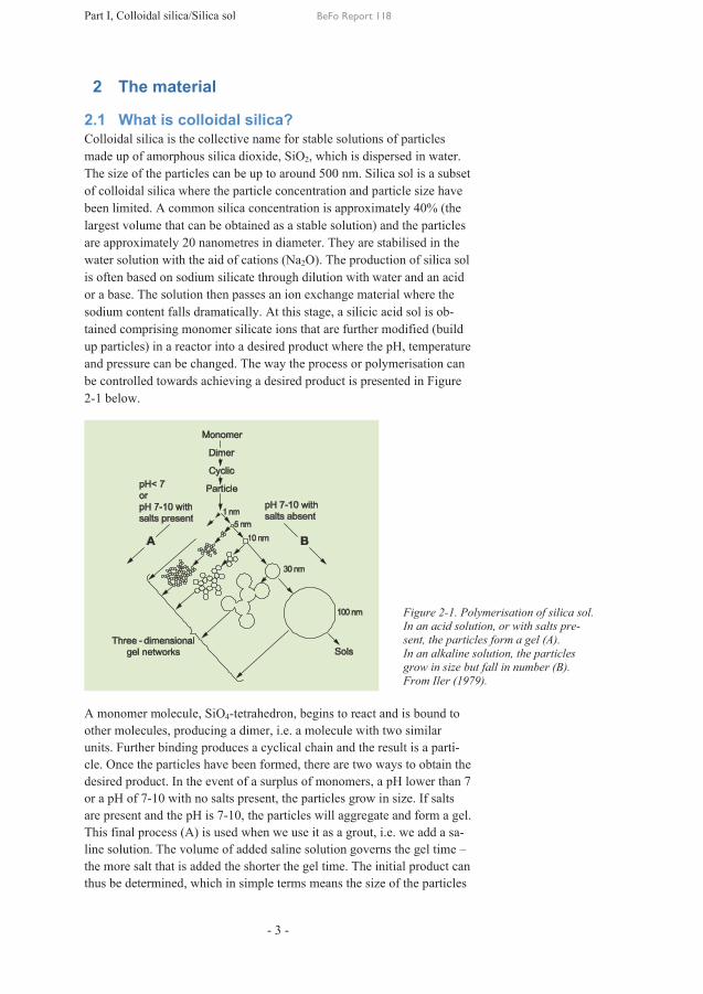
2.1 What is colloidal silica? Colloidal silica is the collective name for stable solutions of particles made up of amorphous silica dioxide, SiO2, which is dispersed in water. The size of the particles can be up to around 500 nm. Silica sol is a subset of colloidal silica where the particle concentration and particle size have been limited. A common silica concentration is approximately 40% (the largest volume that can be obtained as a stable solution) and the particles are approximately 20 nanometres in diameter. They are stabilised in the water solution with the aid of cations (Na2O). The production of silica sol is often based on sodium silicate through dilution with water and an acid or a base. The solution then passes an ion exchange material where the sodium content falls dramatically. At this stage, a silicic acid sol is ob-tained comprising monomer silicate ions that are further modified (build up particles) in a reactor into a desired product where the pH, temperature and pressure can be changed. The way the process or polymerisation can be controlled towards achieving a desired product is presented in Figure 2-1 below.
A monomer molecule, SiO4-tetrahedron, begins to react and is bound to other molecules, producing a dimer, i.e. a molecule with two similar units. Further binding produces a cyclical chain and the result is a parti-cle. Once the particles have been formed, there are two ways to obtain the desired product. In the event of a surplus of monomers, a pH lower than 7 or a pH of 7-10 with no salts present, the particles grow in size. If salts are present and the pH is 7-10, the particles will aggregate and form a gel. This final process (A) is used when we use it as a grout, i.e. we add a sa-line solution. The volume of added saline solution governs the gel time – the more salt that is added the shorter the gel time. The initial product can thus be determined, which in simple terms means the size of the particles
Figure 2-1. Polymerisation of silica sol. In an acid solution, or with salts pre-sent, the particles form a gel (A). In an alkaline solution, the particles grow in size but fall in number (B). From Iler (1979).

Part I, Colloidal silica/Silica sol BeFo Report 118
- 4 -
that are desired. A smaller particle size produces a higher specific surface and is thus more reactive. Normally, a particle size of 16-20 nm is used where the particle size distribution (‘fan curve’), varies depending on the product. It should be borne in mind that the natural condition of silica sol is a gelled state and the processes that take place to keep it liquid are con-trolled. This means that the grout has a ‘use-by date’, at which point the properties deviate significantly from the original properties. The ‘use-by date’ is set by the manufacturer and must always be checked before the product is used.
The practical advantages of silica sol, apart from the penetration capacity, are obvious when it comes to controlling the gelling time of the grout. The technique for conventional grouting, i.e. the pressure and grout that should be used and how the stop criteria are designed, is normally based on past experience. Furthermore, the planned time for grouting has not been known. With silica sol, the gel time can be controlled and the grout-ing time per hole can vary from a few minutes to several hours if pre-ferred. The gel time also controls the penetration length in that a short gel time produces a short penetration length and vice versa. In certain cases, the aim is to limit the penetration length to minimise usage and wastage in conjunction, for example, with surface leakage and post-grouting situa-tions. Figure 2-2 shows how the viscosity growth appears for different mixing ratios with the saline solution. Initially, silica sol has a consistent-ly low viscosity (approximately 10 mPas, water = 1 mPas). After a cer-tain period of time, the viscosity increases substantially and silica sol sets to a firm gel.
2.2 Available products The commercial products made from silica sol that are available in Swe-den are mainly Meyco MP320 and Meyco MP320T. At an early stage in the development of silica sol there was also Meyco MP320C, which is free of biocides (anti-mould agent) as well as silica sols intended for re-search purposes, such as ‘Eka Gel Exp 36’ and ‘Cembinder U22’, which are identical to Meyco MP320C but under another name.
Meyco MP320 is at present the most common product and is manufac-tured in Sweden. MP320T is manufactured mainly in Germany and the
0,0
2,0
4,0
0 180 360 540 720 900 1080 1260 1440 1620 1800 1980 2160 2340
Tid (sec)
Visk
osite
t (Pa
s)
Ratio 5:1
Ratio 6:1
Ratio 6,5:1
Ratio 7:1
Ratio 7,3:1
Ratio 8:1Figure 2-2. Viscosity curves for a silica salt product at different mixing ratios (based on weight) for the saline solution at a tem-perature of 8°C.
Vis
cosi
ty [P
as]
Time [s]

Part I, Colloidal silica/Silica sol BeFo Report 118
- 5 -
difference between these MP320s is that the particle content is only 30% compared to the Swedish level of 35-40%. Nowadays, there is also Meyco MP325, which has an even lower silicon content, 15%.
2.3 Silica sol, penetration and sealing properties Properties in silica sol related to grouting:
· Penetrability into small fractures · Flow properties/rheology, i.e. viscosity and gel time · Gelling · Longevity · Sealing/in situ permeability
The penetrability capacity depends largely on the particle size. As the sil-ica sol particles are small, 5-100 nm, the penetrability is initially good even in the smallest of fractures. The good penetrability decreases as soon as the particles begin to form larger networks in conjunction with gelling. Consequently, grouting should commence immediately after mixing the saline solution, which starts the gelling, in order to retain good penetrability.
The flow properties, the rheology, describe the flow properties for a fluid, in this case the grout. Silica sol behaves in the same way as a ‘Newtonian fluid’ for large parts of the flow process and for a Newtonian fluid the viscosity is the only material parameter that describes the flow properties of the fluid. By comparison, a cement grout is normally described as a ‘Bingham fluid’
As soon as the gelling starts, the grout will acquire the properties of a Bingham fluid, i.e. with the material parameters viscosity and flow limit. The exact border between a Newtonian fluid and a Bingham fluid is diffi-cult to determine and is basically a question of definition. In practical terms, it is not of major importance. Figure 2-3 below illustrates the dif-ference between a Bingham fluid and a Newtonian fluid.
Figure 2-3. A schematic graph to illustrate a Newtonian fluid and a Bingham fluid as well as their rheological difference.

Part I, Colloidal silica/Silica sol BeFo Report 118
- 6 -
The difference between a Newtonian fluid of the silica sol type and a Bingham fluid of the cement type is that the Newtonian fluid comes into motion immediately the shearing force is exerted. In the case of a Bing-ham fluid, the exerted shearing speed must be greater than the shearing stress of the grout, known as the flow limit. In the same way, once the shearing force falls below the flow limit, the material stops. For a Newto-nian fluid, the material always moves as long as the shearing stress is act-ing on the liquid. The gradient of the curve in Figure 2-3 is the viscosity. A material with a high viscosity flows more sluggishly or slowly than a fluid with a lower viscosity at the same exerted shearing speed. For a gel-ling liquid, the mobilised shearing stresses along the penetration length are balanced by the exerted pressure. Finally, the shearing stresses along the penetration length will be equal to the pressure and the liquid will stop. Such a penetration curve is shown in Figure 2-4 below.
As the figure shows, the penetration speed is initially rapid and as the penetration length increases, the speed decreases. Finally, the mobilised shearing stresses (a product of both the penetration length and the in-crease in viscosity) are so high that the penetration ceases. The penetra-tion length can thus be controlled with the aid of exerted pressure and se-lected viscosity increase. Rapid gelling produces a short penetration length and vice versa. It is this ratio that must be borne in mind in the grouting design and this is covered extensively in this guide.
2.3.1 Selected concepts Gel time, TG = the time from when the silica sol and saline solution are mixed until it has gelled. The mixture is considered to have gelled when a beaker filled with the mixture can be turned 90° without the liquid flow-ing. Unit: minutes.
Initial viscosity, µ0 = viscosity of the mixture directly after mixing. This is determined using a rheometer. Unit: Pas
0,00
0,50
1,00
1,50
2,00
2,50
0,0040,0060,0080,0100,0120,0140,0160,0180,020
0 500 1000 1500 2000
Visc
osity
, µ [P
as]
Time [s]
Viscosity increase and penetration length
Inträngning
Pene
tratio
n le
ngth
[m]
InträngningInträngningInträngningPenetration
ViscosityFigure 2-4. The penetration of sili-ca sol over time. This figure also includes the viscosity increase.

Part I, Colloidal silica/Silica sol BeFo Report 118
- 7 -
Gel induction time, tG = the time it takes for the viscosity to double in re-lation to the initial viscosity.
Pressure, p, and overpressure, Δp – the pressure at the grouting pump is the same as the exerted overpressure plus groundwater pressure.
Grouting time – the time the pressure remains at the packer and until the pump is turned off and the packer is closed. Unit: minutes
Effective grouting time – the effective grouting time commences when the packer is open, the design pressure is achieved and lasts for as long as the design pressure is maintained. For definitions, see Figure 2-5 below.
2.3.2 Gel induction time and penetration length The gel time, gel induction time and viscosity in relation to the time is shown in Figure 2-6 below.
The penetration into a fracture is linked to the viscosity curve, which shows that the penetration achieves almost the maximum length before the gel time is reached (Figure 2-7).
Figure 2-5. Illustration of the grouting time generally and the effec-tive grouting time and pumping time specifical-ly.
Figure 2-6. Schematic il-lustration of the terms ‘gel induction time’ and ‘gel time’.

Part I, Colloidal silica/Silica sol BeFo Report 118
- 8 -
In the laboratory, many tests are being carried out to determine how the penetration of gelling liquid takes place. As a rule of thumb, it can be said that the maximum possible penetration, Imax is achieved at half the gel time, TG. The liquid at this point is still very free-flowing. If no gelling had taken place, penetration would have continued indefinitely as long as the driving force was active. The viscosity only governs the penetration speed; a low-viscosity liquid has a short penetration and vice versa. The gelling results in a visible stop in the penetration and an increase in strength. The time the pressure must be exerted, over half the gel time, depends on the hydrogeological conditions, the hydraulic gradient and the risk of erosion of the grout. In deep tunnels, approximately 150-500 me-tres, the risk of erosion is greater and the grouting time must be longer than half the gel time, whilst in shallow tunnels, less than 100 metres, and if the hydraulic gradient is low, the risk of erosion is lower and the grout-ing time can be shorter, i.e. half the gel time.
The maximum penetration length for a two-dimensional flow (2-D) with silica sol, Imax, 2-D, is calculated as (Gustafson and Funehag, 2008a and 2008b)
02max, 6
45.0m
GD
ptbI D××=- (2-1)
where b is the hydraulic fracture aperture, Δp is the exerted overpressure, tG is the gel induction time and µ0 is the initial viscosity in silica sol. The gel induction time is the time it takes for the initial viscosity to double. After the gel induction time, the increase in viscosity is rapid and the penetration capacity decreases dramatically. A rule of thumb is that the gel induction time is one-third of the gel time /Funehag, 2007/. The gel induction time must not be confused with the gel time.
The strength of silica sol can generally be determined by the particle size (specific surface), size distribution and particle content. The same proper-ties also control the gel time of silica sol. In very simple terms, it can be
Figure 2-7. Penetration in relation to viscosity. The un-broken line is the viscosity curve for a silica sol. The broken line is the penetration for silica sol and for compar-ison purposes the dotted line is for a non-gelling silica sol (consistently low viscosity).

Part I, Colloidal silica/Silica sol BeFo Report 118
- 9 -
said that the strength increases in a product with a higher particle content. However, higher strength for a product with a low particle content could be achieved if compensation is made in the form of a broader particle dis-tribution, i.e. a mixture of particle sizes. However, it has not been possi-ble to verify this approach completely through literature studies, due in part to the lack of information about material properties and to the fact that several products have not been compared with each other in the same study.
In situ permeability describes how permeable the grout is in reality. Wa-ter ingression should naturally be lower than the desired permeability of the rock that is to be sealed. Silica sol has properties that bind the water in the solution network. Indirect tests carried out on the material Eka gel Exp 36 reveal a hydraulic conductivity, K, of approximately 10-10-10-11 m/s (Butron et al, 2007). The tested product had an average particle size of 16 nm with a weight ratio of 35%.
Part I, Colloidal silica/Silica sol BeFo Report 118
- 10 -
2.4 Silica sol, other properties Other aspects, apart from the pure grouting properties, that could be of importance to how grouting with silica sol ought to be executed are as follows.
· Mechanical
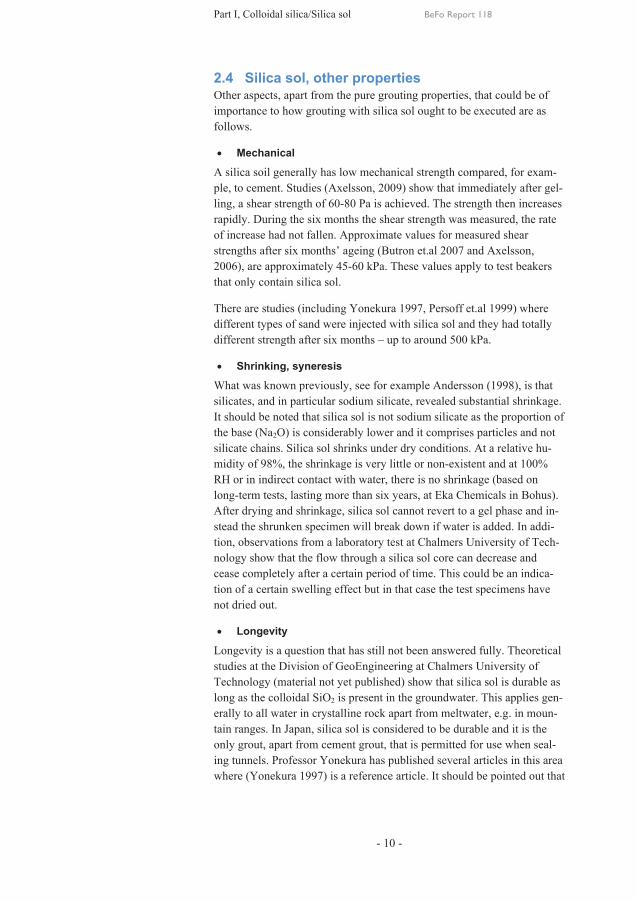
A silica soil generally has low mechanical strength compared, for exam-ple, to cement. Studies (Axelsson, 2009) show that immediately after gel-ling, a shear strength of 60-80 Pa is achieved. The strength then increases rapidly. During the six months the shear strength was measured, the rate of increase had not fallen. Approximate values for measured shear strengths after six months’ ageing (Butron et.al 2007 and Axelsson, 2006), are approximately 45-60 kPa. These values apply to test beakers that only contain silica sol.
There are studies (including Yonekura 1997, Persoff et.al 1999) where different types of sand were injected with silica sol and they had totally different strength after six months – up to around 500 kPa.
· Shrinking, syneresis
What was known previously, see for example Andersson (1998), is that silicates, and in particular sodium silicate, revealed substantial shrinkage. It should be noted that silica sol is not sodium silicate as the proportion of the base (Na2O) is considerably lower and it comprises particles and not silicate chains. Silica sol shrinks under dry conditions. At a relative hu-midity of 98%, the shrinkage is very little or non-existent and at 100% RH or in indirect contact with water, there is no shrinkage (based on long-term tests, lasting more than six years, at Eka Chemicals in Bohus). After drying and shrinkage, silica sol cannot revert to a gel phase and in-stead the shrunken specimen will break down if water is added. In addi-tion, observations from a laboratory test at Chalmers University of Tech-nology show that the flow through a silica sol core can decrease and cease completely after a certain period of time. This could be an indica-tion of a certain swelling effect but in that case the test specimens have not dried out.
· Longevity
Longevity is a question that has still not been answered fully. Theoretical studies at the Division of GeoEngineering at Chalmers University of Technology (material not yet published) show that silica sol is durable as long as the colloidal SiO2 is present in the groundwater. This applies gen-erally to all water in crystalline rock apart from meltwater, e.g. in moun-tain ranges. In Japan, silica sol is considered to be durable and it is the only grout, apart from cement grout, that is permitted for use when seal-ing tunnels. Professor Yonekura has published several articles in this area where (Yonekura 1997) is a reference article. It should be pointed out that
Part I, Colloidal silica/Silica sol BeFo Report 118
- 11 -
research is being conducted in this area to acquire an understanding of the mechanical degradation mechanisms for grout.
· Environmental and health aspects
No demonstrable negative health effects have been reported. It should be borne in mind, however, that silica sol is slightly alkaline (pH 9-10) and it could cause irritation if it were to come into contact with the skin and eyes.
The use of colloidal particles in society is on the increase. It is common in paints, drinks, cosmetics and so on, and the long-term environmental effects of its use have not yet been investigated although there are suspi-cions that it could render watercourses turbid.
· Storage and shelf life
Silica sol also contains water, which means that it must not freeze or be exposed to major temperature changes. The recommended storage tem-perature is 5-35 degrees Celsius. High temperatures could speed up mi-crobiological growth and reduce long-term stability. At normal storage temperatures, the long-term stability is guaranteed for at least 18 months for Meyco MP320 and MP320T. If stored for longer, the viscosity and the specific surface area ought to be checked, which for the most part can be carried out by the supplier.
· Examples of requirements regarding material information that can be stipulated in a construction document - Silicon content - Particle size, specific surface area - Strength during gelling - Strength after a certain period of time following conclusion of
grouting - Type of accelerator, NaCl or CaCl, and the concentration

Part II, Grouting procedure BeFo Report 118
- 12 -
3 Execution of silica sol grouting Execution is preceded by a grouting design or plan. The design involves pro-posed geometries for a grouting fan, the grout that is to be used, the pressure and times that are suitable as a starting point and the checks that need to be made to ensure the result. The equipment is stated indirectly in the form of a demand specification, which is obtained by knowing what pressure and times will be necessary. Appendix A contains an example of a grouting design, which is linked to a later chapter on execution. The essence of such a design is summarised in what is known as a design window, see Figure 3-1.
Figure 3-1 illustrates that when choosing different pressures and times (gel in-duction time), different penetration lengths are obtained in a hydraulic fracture aperture of 30 µm. The penetration lengths govern the choice of borehole dis-tance, c-distance, between the boreholes in the fan and the gel induction time, thus governing how long each borehole needs to be pumped. Furthermore, the pressure is selected to avoid the risk of lifting the rock or causing breakage, resulting in a need for more grout than is necessary. At the same time, the pressure must not be too low, as this would result in long grouting times to achieve a sufficient penetration length.
3.1 Suitable equipment currently available At present, all mobile equipment produced for cement grouting also works for silica sol. It must be borne in mind that silica sol does not have any ‘lubricat-ing’ effect on the equipment in the way that cement does. Routine inspection of the pumps and other equipment therefore needs to be carried out more regu-larly than is the case with cement grouting.
Silica sol for grouting comes in the form of two liquid solutions, one with sili-ca sol and one with a saline solution. They are normally supplied in 1 m3 plas-tic tanks with steel cages although there are smaller containers. Both the solu-tions are pumped over to the grouting equipment using barrel pumps. These must be powerful, at least 30 l/min (preferably with a flow meter) to avoid the mixing becoming a ‘bottleneck’. There are two alternatives for weighing silica
Figure 3-1. Penetration lengths for a dimensioning hydraulic fracture width, 30 µm, as a function of the grouting overpressure and gel induction time. The re-quired penetration length of 2.63 m is shown as a horizontal, broken line.

Part II, Grouting procedure BeFo Report 118
- 13 -
sol. The silica sol can be weighed in the agitator or directly in the mixer. In both cases there must be a measurement system for either volume or weight. The agitator measures the weight relatively accurately for large batches – more than 50 l. For smaller batches, the accuracy ought to be checked and the margin of error should not exceed 5%.
The weighing system for the mixer often comprises just one load cell and is only there to show whether there is material in the mixer or not. The level of accuracy is thus insufficient for automated recipe weighing. The mixer can be supplemented with up to three load cells, which can also compensate for the equipment not standing completely horizontally. If the barrel pumps have a more exact flow meter, the pumps can be used to pump up the correct volume into the mixer. On slightly more advanced barrel pumps, they can be set to al-ways pump a certain volume before switching off. These electronic control systems, on and off switches, are already fitted to newer grouting equipment. The correct volume of saline solution can be pumped in the same way, using barrel pumps or scales. It should be borne in mind that the volume of saline solution is normally one-quarter to one-fifth of the volume of silica sol, which means that the measurement accuracy range is lower than for the silica sol. The saline solution can also be weighed using what are mostly separate addi-tive arrangements, used mainly for different additives for cement. Automated dosage and mixing are preferable to save time when mixing.
Figure 3-2. 1m3 con-tainer with silica sol and a saline solution from a project in one of the Telia tunnels.
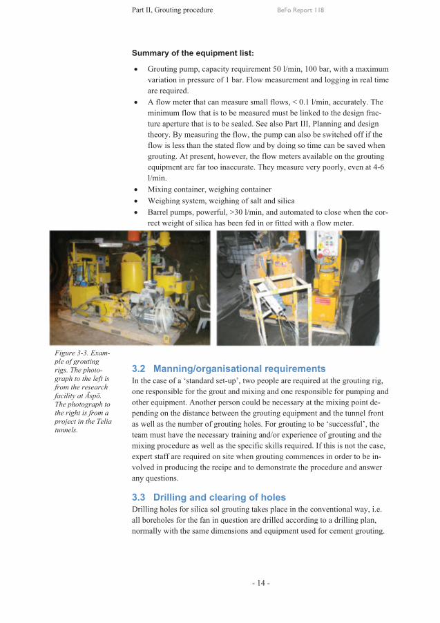
Figure 3ple of grouting rigs. The photgraph to the left is from the research facility atThe photograph to the right is from project in the Telia tunnels.
3-3. Exam-ple of grouting rigs. The photo-graph to the left is from the research
at Äspö. he photograph to
the right is from a project in the Telia
Part II, Grouting procedure
Summary of the equipment list
· Groutingvariation are required
· A flowminimum flow that is to be measured ture theoryflow is less than the stated flow and by doing so time can be saved when grouting. At present, however, the flow meters equipment are far too inaccurate. Thel/min.
· Mixing container, weighing container· Weighing system, weighing of salt and silica· Barrel pumps, powerful,
rect
3.2 Manning/organisational requirementsIn the case of a one responsible for the grout and mixing other equipment. Another person could be necessary at the pending on the distance between the as well asteam must havemixing procedure as well as the specific skills required. If this is not the caseexpert staff are required on site when grouting commences volved in any questions.
3.3 Drilling and clearing of holesDrilling holes for silica sol grouting takes place in the conventional way, i.e. all boreholes for the normally with
Part II, Grouting procedure
ary of the equipment list
routing pump, capacity requirementvariation in pressurare required. A flow meter that can measure small flowsminimum flow that is to be measured ture aperture that is to be sealed. See also Parttheory. By measuring the flow, the pump can also be switched flow is less than the stated flow and by doing so time can be saved when grouting. At present, however, the flow meters equipment are far too inaccurate. Thel/min.
ixing container, weighing containereighing system, weighing of salt and silica
arrel pumps, powerful, weight of silica has been fed
Manning/organisational requirementsIn the case of a ‘standard setone responsible for the grout and mixing other equipment. Another person could be necessary at the pending on the distance between the as well as the number of grouting holes. For grouting to be
must have the necessary mixing procedure as well as the specific skills required. If this is not the casexpert staff are required on site when grouting commences
volved in producing the recipeany questions.
Drilling and clearing of holesDrilling holes for silica sol grouting takes place in the conventional way, i.e. all boreholes for the fannormally with the same dimensions and equipment used for cement grouting
Part II, Grouting procedure
ary of the equipment list
pump, capacity requirementin pressure of 1 bar.
meter that can measure small flowsminimum flow that is to be measured
that is to be sealed. See also Part. By measuring the flow, the pump can also be switched
flow is less than the stated flow and by doing so time can be saved when grouting. At present, however, the flow meters equipment are far too inaccurate. The
ixing container, weighing containereighing system, weighing of salt and silica
arrel pumps, powerful, >30 l/min, weight of silica has been fed
Manning/organisational requirementsstandard set-up’, t
one responsible for the grout and mixing other equipment. Another person could be necessary at the pending on the distance between the
the number of grouting holes. For grouting to be necessary training and/or experience of grouting and the
mixing procedure as well as the specific skills required. If this is not the casexpert staff are required on site when grouting commences
producing the recipe and to
Drilling and clearing of holesDrilling holes for silica sol grouting takes place in the conventional way, i.e.
fan in question are the same dimensions and equipment used for cement grouting
BeFo Report 118
- 14 -
ary of the equipment list:
pump, capacity requirement 50 l/min, 100 bar, 1 bar. Flow measurement and lo
meter that can measure small flowsminimum flow that is to be measured must
that is to be sealed. See also Part. By measuring the flow, the pump can also be switched
flow is less than the stated flow and by doing so time can be saved when grouting. At present, however, the flow meters equipment are far too inaccurate. They measure very poorly
ixing container, weighing container eighing system, weighing of salt and silica
>30 l/min, and automated to close when the weight of silica has been fed in or fitted with
Manning/organisational requirements, two people are required at the grouting rig,
one responsible for the grout and mixing and other equipment. Another person could be necessary at the pending on the distance between the grouting
the number of grouting holes. For grouting to be training and/or experience of grouting and the
mixing procedure as well as the specific skills required. If this is not the casexpert staff are required on site when grouting commences
and to demonstrat
Drilling and clearing of holesDrilling holes for silica sol grouting takes place in the conventional way, i.e.
question are drilledthe same dimensions and equipment used for cement grouting
BeFo Report 118
50 l/min, 100 bar, measurement and lo
meter that can measure small flows, < 0.1 l/minmust be linked to the d
that is to be sealed. See also Part III, Planning and design. By measuring the flow, the pump can also be switched
flow is less than the stated flow and by doing so time can be saved when grouting. At present, however, the flow meters available on the grouting
measure very poorly
eighing system, weighing of salt and silica automated to close when the
fitted with a flow meter.
Manning/organisational requirementso people are required at the grouting rig,
one responsible for pumpinother equipment. Another person could be necessary at the
grouting equipment and the number of grouting holes. For grouting to be
training and/or experience of grouting and the mixing procedure as well as the specific skills required. If this is not the casexpert staff are required on site when grouting commences
onstrate the procedure and
Drilling and clearing of holes Drilling holes for silica sol grouting takes place in the conventional way, i.e.
drilled according to a drilling plan, the same dimensions and equipment used for cement grouting
BeFo Report 118
50 l/min, 100 bar, with a maximum measurement and logging in real time
1 l/min, accuratelybe linked to the design
lanning and design. By measuring the flow, the pump can also be switched off if the
flow is less than the stated flow and by doing so time can be saved when available on the grouting
measure very poorly, even at
automated to close when the a flow meter.
Manning/organisational requirements o people are required at the grouting rig,
one responsible for pumpinother equipment. Another person could be necessary at the mixing point
equipment and the tunnel front the number of grouting holes. For grouting to be ‘successful
training and/or experience of grouting and the mixing procedure as well as the specific skills required. If this is not the casexpert staff are required on site when grouting commences in order to be i
the procedure and answer
Drilling holes for silica sol grouting takes place in the conventional way, i.e. according to a drilling plan,
the same dimensions and equipment used for cement grouting
with a maximum in real time
accurately. The esign frac-
lanning and design off if the
flow is less than the stated flow and by doing so time can be saved when available on the grouting
even at 4-6
automated to close when the cor-
o people are required at the grouting rig, one responsible for pumping and
mixing point de-the tunnel front
successful’, the training and/or experience of grouting and the
mixing procedure as well as the specific skills required. If this is not the case, to be in-
answer
Drilling holes for silica sol grouting takes place in the conventional way, i.e. according to a drilling plan,
the same dimensions and equipment used for cement grouting.
Part II, Grouting procedure BeFo Report 118
- 15 -
Silica sol does not require any further clearance in the hole as opposed to the high-pressure flushing that is normally required in conjunction with cement grouting.
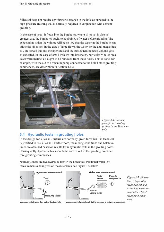
In the case of small inflows into the boreholes, where silica sol is also of greatest use, the boreholes ought to be drained of water before grouting. The expectation is that the volume will be so low that the water in the borehole can dilute the silica sol. In the case of large flows, the water, or the undiluted silica sol, are forced out into the apertures and the subsequent injected volume gels as expected. In the case of small inflows into boreholes, particularly holes on a downward incline, air ought to be removed from these holes. This is done, for example, with the aid of a vacuum pump connected to the hole before grouting commences, see description in Section 4.1.2.
3.4 Hydraulic tests in grouting holes In the design for silica sol, criteria are normally given for when it is technical-ly justified to use silica sol. Furthermore, the mixing conditions and batch vol-umes are obtained based on results from hydraulic tests in the grouting holes. Consequently, hydraulic tests should be carried out in the grouting holes be-fore grouting commences.
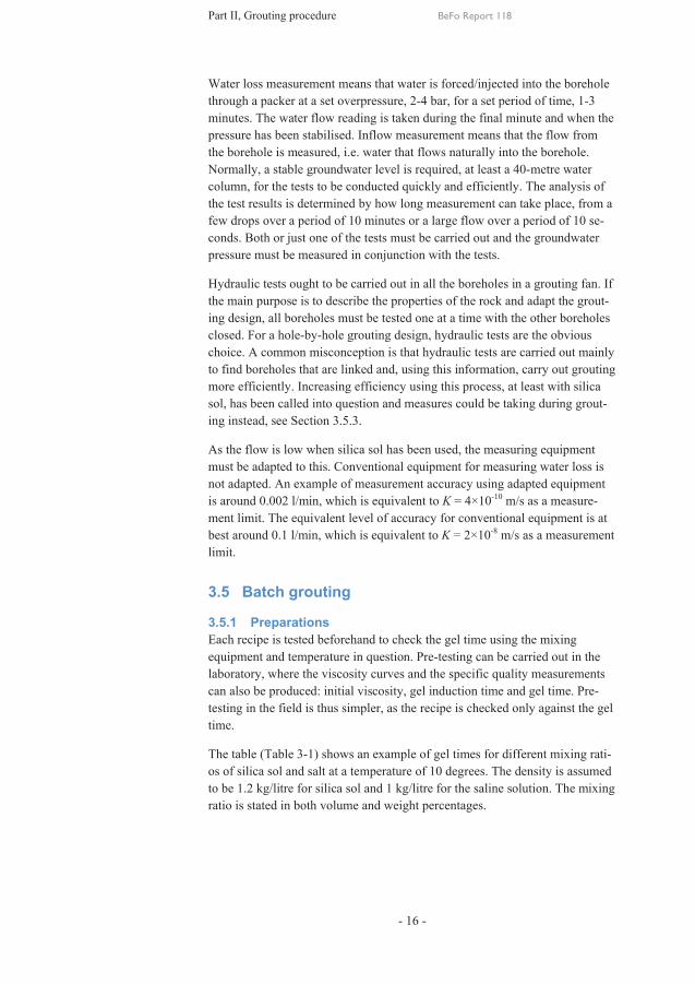
Normally, there are two hydraulic tests in the boreholes, traditional water loss measurements and ingression measurements, see Figure 3-5 below.
Figure 3-4. Vacuum pump from a sealing project in the Telia tun-nels.
Figure 3-5. Illustra-tion of ingression measurement and water loss measure-ment with related measuring equip-ment.
Part II, Grouting procedure BeFo Report 118
- 16 -
Water loss measurement means that water is forced/injected into the borehole through a packer at a set overpressure, 2-4 bar, for a set period of time, 1-3 minutes. The water flow reading is taken during the final minute and when the pressure has been stabilised. Inflow measurement means that the flow from the borehole is measured, i.e. water that flows naturally into the borehole. Normally, a stable groundwater level is required, at least a 40-metre water column, for the tests to be conducted quickly and efficiently. The analysis of the test results is determined by how long measurement can take place, from a few drops over a period of 10 minutes or a large flow over a period of 10 se-conds. Both or just one of the tests must be carried out and the groundwater pressure must be measured in conjunction with the tests.
Hydraulic tests ought to be carried out in all the boreholes in a grouting fan. If the main purpose is to describe the properties of the rock and adapt the grout-ing design, all boreholes must be tested one at a time with the other boreholes closed. For a hole-by-hole grouting design, hydraulic tests are the obvious choice. A common misconception is that hydraulic tests are carried out mainly to find boreholes that are linked and, using this information, carry out grouting more efficiently. Increasing efficiency using this process, at least with silica sol, has been called into question and measures could be taking during grout-ing instead, see Section 3.5.3.
As the flow is low when silica sol has been used, the measuring equipment must be adapted to this. Conventional equipment for measuring water loss is not adapted. An example of measurement accuracy using adapted equipment is around 0.002 l/min, which is equivalent to K = 4×10⁻¹⁰ m/s as a measure-ment limit. The equivalent level of accuracy for conventional equipment is at best around 0.1 l/min, which is equivalent to K = 2×10⁻⁸ m/s as a measurement limit.
3.5 Batch grouting
3.5.1 Preparations Each recipe is tested beforehand to check the gel time using the mixing equipment and temperature in question. Pre-testing can be carried out in the laboratory, where the viscosity curves and the specific quality measurements can also be produced: initial viscosity, gel induction time and gel time. Pre-testing in the field is thus simpler, as the recipe is checked only against the gel time.
The table (Table 3-1) shows an example of gel times for different mixing rati-os of silica sol and salt at a temperature of 10 degrees. The density is assumed to be 1.2 kg/litre for silica sol and 1 kg/litre for the saline solution. The mixing ratio is stated in both volume and weight percentages.

Part II, Grouting procedure BeFo Report 118
- 17 -
Table 3-1. Examples of gel times, TG, for different mixing ratios at a temperature of 10°C. The table shows the size of a batch measured either in weight or in volume.
Ratio Weights Weight ratio Volume ratio TG (10°C) Kg sol
Kg saline solution Per kg sol
Kg saline solution
4:1 3.3:1 22.5 min 100 25 1 0.25
4.5:1 3.75:1 30 min 102.6 22.8 1 0.22
5:1 4.2:1 38 min 105 21 1 0.2
Ratio Volumes Weight ratio Volume ratio TG (10°C)
Litres, sol
Litres, sa-line solu-tion
Per litre sol
Litres, sa-line solu-tion
4:1 3.3:1 22.5 min 83.3 25 1 0.3
4.5:1 3.75:1 30 min 85.5 22.8 1 0.27
5:1 4.2:1 38 min 87.5 21 1 0.24
The final two columns can be used as a starting point to multiply the size based on a selected batch size.
The gel time is strongly dependent on the temperature. As a rule of thumb, halving the temperature (°C) produces a doubling of the gel time. The above mixing ratios (weight ratios) result in the table below, which shows how the gel time varies according to temperature (Table 3-2). It should be noted that the temperature that the mixing ratio should be prepared for is the temperature in the rock and this is what determines the pumping time. If the ambient air temperature is higher than in the mixture, the silica sol will rapidly assume the ambient temperature in the rock during grouting of the small rock fractures.

Part II, Grouting procedure BeFo Report 118
- 18 -
Table 3-2. Examples of how the gel times, TG, can vary depending on the temperature of the different mixing ratios shown in Table 3-1.
Weight ratio
5:1 Weight ra-tio
4.5:1 Weight ratio
4:1
Temp Gel time, TG Temp Gel time, TG
Temp Gel time, TG
[°C] [min] [°C] [min] [°C] [min]
5 43 5 35 5 27.5
10 38 10 30 10 22.5
15 33 15 25 15 17.5
20 28 20 20 20 12.5
25 23 25 15 25 7.5
3.5.2 Mixing and equipment The most common mixing method to date in a number of projects has been what is termed batch grouting. Batch grouting means that a prescribed volume of silica sol is mixed for grouting a hole and then the whole or part of the batch is injected into the hole. The prescribed volume that needs to be mixed for a batch normally depends on the results of the hydraulic tests, see Section 6.2.2, as an initial estimate as well as the volume in hoses and grouting holes. A normal batch is approximately 200-250 kg.
When it is approaching the end, the next batch is mixed. The remaining vol-ume must not be used for the next grouting hole due to gelling, see also Chap-ter 3.6, Development of the mixing procedure and equipment.
Batch mixing makes it easy to control the gel time. The mixing of silica sol and salt is done in the mixer on a conventional grouting platform. The mixture of silica sol and a saline solution is best done as close to the pump as possible, ideally in the mixer, which reduces the number of components that need to be cleaned.
The silica sol is weighed directly in the mixing container at the same time as the saline solution is weighed out in an additive tank. When the silica sol has been weighed, the saline solution is added automatically when the mixer is running. When the salt has been added, the mixer is allowed to run for 20-30 seconds depending on the power of the mixer. After this time, the gelling pro-cess for the mixture commences. A beaker sample is taken from the mixer immediately after mixing to check the gel time.
The pump is started, the hoses are filled with the grout and grouting can com-mence. During grouting, mixing is carried out in the mixer. The beaker test is labelled and checked regularly until gelling has been noted (a stable mixture has been obtained when the beaker can be tipped 90°), see Figure 3-6 below.

Part II, Grouting procedure
When the gel time has been achieved, a straight surface is obtained but not necessarily entirely vertical (depending on the slip from the surface). feeling the surface of the sample with your fingertip. If youimpression on the surface of the sample without it sticking to your fingers this is a further indication that the gel time has been
3.5.3 GroutingExamples shown below
1) Setting out2) Drilling of a 3) Possible
straightness.4) All boreholes are
water loss can available and if possible
5) Packer6) Hydraulic tests: Natural in
in l/min
7) Groutingmoved in a zigzag fashion
8) Mixing according to the mixing procedure, 9) Hoses are filled with the mixture
packer10) The design pressure must be achieved as quickly as poss
be controlled with the flow, i.e. maximum flow initially11) Grouting
mixture, pressure and flow are checked regularly. In the event of posible unexpected observations, action can be tak4
Silica sol
Part II, Grouting procedure
When the gel time has been achieved, a straight surface is obtained but not necessarily entirely vertical (depending on the slip from the surface). feeling the surface of the sample with your fingertip. If youimpression on the surface of the sample without it sticking to your fingers this is a further indication that the gel time has been
Grouting Examples of the work process in conjunction with silica shown below.
Setting out of boreholesDrilling of a Possible checking of the setting outstraightness.All boreholes are water loss can available and if possiblePacker. The Hydraulic tests: Natural inin all boreholesl/min, the groundwater pressure should also be measured.
a) The results of the tests can be evaluated before choosing the mixtureis determined. This can be done
b) The results are used to update the procedure for the next and to evaluate the results
Grouting commences in the lowest located moved in a zigzag fashion Mixing according to the mixing procedure, Hoses are filled with the mixture packer. The design pressure must be achieved as quickly as possbe controlled with the flow, i.e. maximum flow initiallyGrouting continues until the mixture, pressure and flow are checked regularly. In the event of posible unexpected observations, action can be tak4. If a connected
Silica sol
Close to the gel time
Part II, Grouting procedure
When the gel time has been achieved, a straight surface is obtained but not necessarily entirely vertical (depending on the slip from the surface). A further tipfeeling the surface of the sample with your fingertip. If youimpression on the surface of the sample without it sticking to your fingers this is a further indication that the gel time has been
of the work process in conjunction with silica
of boreholes.Drilling of a grouting fan
checking of the setting outstraightness. All boreholes are flushedwater loss can possibly be carried out at the same time available and if possible
The packer is fitted 1Hydraulic tests: Natural in
all boreholes. In those holes where , the groundwater pressure should also be measured.
The results of the tests can be evaluated before choosing the mixture. Among other thi
determined. This can be doneThe results are used to update the procedure for the next and to evaluate the results
commences in the lowest located moved in a zigzag fashion Mixing according to the mixing procedure, Hoses are filled with the mixture
The design pressure must be achieved as quickly as possbe controlled with the flow, i.e. maximum flow initially
continues until the mixture, pressure and flow are checked regularly. In the event of posible unexpected observations, action can be tak
connected hole is discovered, see below
u ω
Close to the gel
BeFo Report 118
- 19 -
When the gel time has been achieved, a straight surface is obtained but not necessarily entirely vertical (depending on the
tip to see whether the sample feeling the surface of the sample with your fingertip. If youimpression on the surface of the sample without it sticking to your fingers this is a further indication that the gel time has been
of the work process in conjunction with silica
fan.
checking of the setting out, orientation and measurement of
flushed clean of sludge cuttings. Mbe carried out at the same time connected holes
is fitted 1-1.5 metres into the borehole.Hydraulic tests: Natural ingression, including dripping, are measured
n those holes where , the groundwater pressure should also be measured.
The results of the tests can be evaluated before choosing the mong other things
determined. This can be doneThe results are used to update the procedure for the next and to evaluate the results.
commences in the lowest located moved in a zigzag fashion up into the Mixing according to the mixing procedure, Hoses are filled with the mixture – the hose is connected
The design pressure must be achieved as quickly as possbe controlled with the flow, i.e. maximum flow initially
continues until the groutingmixture, pressure and flow are checked regularly. In the event of posible unexpected observations, action can be tak
hole is discovered, see below
Beaker tipped
BeFo Report 118
When the gel time has been achieved, a straight surface is obtained but not necessarily entirely vertical (depending on the beaker used
whether the sample feeling the surface of the sample with your fingertip. If youimpression on the surface of the sample without it sticking to your fingers this is a further indication that the gel time has been reached.
of the work process in conjunction with silica sol
, orientation and measurement of
sludge cuttings. Mbe carried out at the same time
holes can be identified1.5 metres into the borehole.
, including dripping, are measuredn those holes where there is an ingression
, the groundwater pressure should also be measured.The results of the tests can be evaluated before choosing the
ngs, the batch volume determined. This can be done on site.
The results are used to update the procedure for the next
commences in the lowest located groutinginto the fan as grouting
Mixing according to the mixing procedure, Section 3.5the hose is connected
The design pressure must be achieved as quickly as possbe controlled with the flow, i.e. maximum flow initially
grouting time has been mixture, pressure and flow are checked regularly. In the event of posible unexpected observations, action can be taken as stated in
hole is discovered, see below.
Beaker tipped 90°
Silica sol
Gel time! A straight surface
BeFo Report 118
When the gel time has been achieved, a straight surface is obtained but not used, the sample c
whether the sample has gelled is by feeling the surface of the sample with your fingertip. If your finger makes an impression on the surface of the sample without it sticking to your fingers this
sol grouting are
, orientation and measurement of
sludge cuttings. Measurement of be carried out at the same time if equipment is
can be identified. 1.5 metres into the borehole.
, including dripping, are measuredn ingression, e.g.
, the groundwater pressure should also be measured. The results of the tests can be evaluated before choosing the
the batch volume for each hole
The results are used to update the procedure for the next
grouting holes and grouting takes placeection 3.5.
the hose is connected to a closed
The design pressure must be achieved as quickly as possible and can be controlled with the flow, i.e. maximum flow initially.
time has been reached and the mixture, pressure and flow are checked regularly. In the event of po
en as stated in
time! A straight
Figuer
When the gel time has been achieved, a straight surface is obtained but not the sample could
has gelled is by makes an
impression on the surface of the sample without it sticking to your fingers this
grouting are
, orientation and measurement of
easurement of equipment is
, including dripping, are measured e.g. >2
The results of the tests can be evaluated before choosing the for each hole
The results are used to update the procedure for the next fan
holes and is takes place.
to a closed
ible and can
and the mixture, pressure and flow are checked regularly. In the event of pos-
en as stated in Section
Figure 3-6. Illustration of the test to determine the gel time
Illustration of the test to determine the gel time
Illustration of the beak-test to determine the gel time.

Part II, Grouting procedure BeFo Report 118
- 20 -
12) When the grouting time has been reached, grouting is concluded. The remaining mixture is pumped into the waste container and the equip-ment, including the hoses, are flushed clean.
13) A new mixture is prepared and the procedure is repeated until the final grouting holes with silica sol have been completed.
14) The waiting time after grouting in a concluded fan before the packers are dismantled is: - silica sol: at least three hours for shallow tunnels but this is project-specific and should be dealt with as part of the whole rock extraction cycle.
15) Compile the results recorded from the grouting. 16) Plugging and/or surface grouting (0-1.5 m into the hole) of all bore-
holes with cement/silica sol. This is done if a leaking borehole is dis-covered.
Connected holes
If it is discovered during the grouting process that grout is flowing out of one or several other boreholes, these are known as connected boreholes. In order to discover connected boreholes, it would be appropriate for the packers in the holes that are presumed to be connected to be kept open during grouting. When a connected hole is discovered, the hole being grouted is injected ac-cording to the design (stop criteria below). For connected holes, there are two alternatives: 1) Close the packer and clean out the hole later; 2) Allow it to flow until the hole being grouted has been finished and then grout the con-nected hole.
Step 1, closed packers
1) All packers to the connected holes are closed. This is suitable when several holes are connected.
2) When the current grouting hole has been grouted completely, all connected boreholes are cleaned.
3) Moving from below and upwards in a zigzag fashion, the con-nected holes are grouted according to the design.
4) If further connected holes are noted, these must also be treated as such.
5) The other remaining boreholes are then grouted normally.
Step two, the packers are allowed to flow
1) The connected holes are kept open and allowed to flow until the current grouting hole is completed. This is appropriate if there are only a few connected holes or if the flows of grout from these holes are small.
2) The connected holes are then grouted from the bottom and in a zigzag fashion upwards according to the design.
3) If further connected holes are noted, they must also be treated as such.

Part II, Grouting procedure BeFo Report 118
- 21 -
3.5.4 Stop criteria The main stop criterion for silica sol is the time criterion. When half the gel time has been reached, no further penetration takes place, i.e. the maximum penetration length has been reached, although the pressure must be maintained until the necessary shearing strength for the gel has been achieved. The neces-sary shearing strength depends on the erosion risk; the greater the risk, the longer the grouting time. In simple terms, the risk of erosion is greater for tun-nels that are deeper than 100 metres and less for tunnels that are not as deep. The risk of erosion is reduced by a large overlap between grouting fans and/or grouting of what are termed front holes.
In the following list, the stop criteria are listed in chronological order, i.e. the first point should be the focus but if this does not work the next point could work as a stop criterion. In the case of volume criterion X below, the volume pumped in must be adapted to the expected volume during grouting, see Sec-tion 6.2.3. Initially, the volume pumped in can be set at 1.5 to 2 times the ex-pected grouting volume although adjusted subsequently based on the result. The maximum volume is the highest accepted volume and ought to be adapted in the light of the risk of reaching the surface or nearby facilities but also what can be regarded as an acceptable time to seal a borehole.
1) Grouting continues until the time for the stated design pressure has been reached
2) When a batch is finished, a new batch is mixed and must be pumped for the full period of time.
3) In the case of a total pumped volume of X litres, a quicker batch is mixed (equivalent to approximately half the gel time compared with the earlier batch) and this is also pumped for at least two-thirds of the gel time. Gel times shorter than 10 minutes are difficult to handle and are not recommended.
4) In the case of a total volume of more than X litres, grouting with silica sol is discontinued and the borehole is finally grouted with cement.
5) In the event of a sealed borehole and a plunger that has come to a standstill (movement of less than 1 mm/min) pumping can be discon-tinued.
3.5.5 Checks on grouting material In conjunction with normal batch pumping, the gel time can be checked easily using beaker samples as an ongoing sampling process. In the first fans, a beaker sample is taken of each batch mixed. When repeatability is achieved, the testing can become less frequent, with checks carried out on every third to fifth batch. Checks made during grouting of silica sol, as well as the equipment, are shown in Table 3-3 below.
Part II, Grouting procedure BeFo Report 118
- 22 -
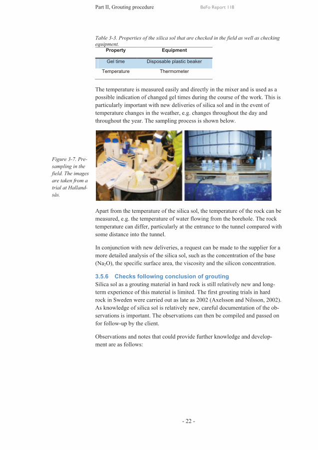
Table 3-3. Properties of the silica sol that are checked in the field as well as checking equipment.
Property Equipment
Gel time Disposable plastic beaker
Temperature Thermometer
The temperature is measured easily and directly in the mixer and is used as a possible indication of changed gel times during the course of the work. This is particularly important with new deliveries of silica sol and in the event of temperature changes in the weather, e.g. changes throughout the day and throughout the year. The sampling process is shown below.
Apart from the temperature of the silica sol, the temperature of the rock can be measured, e.g. the temperature of water flowing from the borehole. The rock temperature can differ, particularly at the entrance to the tunnel compared with some distance into the tunnel.
In conjunction with new deliveries, a request can be made to the supplier for a more detailed analysis of the silica sol, such as the concentration of the base (Na2O), the specific surface area, the viscosity and the silicon concentration.
3.5.6 Checks following conclusion of grouting Silica sol as a grouting material in hard rock is still relatively new and long-term experience of this material is limited. The first grouting trials in hard rock in Sweden were carried out as late as 2002 (Axelsson and Nilsson, 2002). As knowledge of silica sol is relatively new, careful documentation of the ob-servations is important. The observations can then be compiled and passed on for follow-up by the client.
Observations and notes that could provide further knowledge and develop-ment are as follows:
Figure 3-7. Pre-sampling in the field. The images are taken from a trial at Halland-sås.

Part II, Grouting procedure BeFo Report 118
- 23 -
In the boreholes following grouting
Preconditions
Gelled plug Dry boreholes
Running or the plug is forced out Groundwater pressure, gel times
Leaking boreholes The leak before and after grouting
Below is a brief description of the observations
- Has the silica sol gelled in the boreholes or not?
Sometimes, it is noted that the borehole plug has ‘moved out’ when the packer has been removed. The reasons for this have not been investigated fully alt-hough there are a number of factors, such as a dry hole from the beginning (trapped air that forces the plug out), dilution of the silica sol, which reduces the strength (another form of pumping could be necessary). The borehole had not been pumped for a sufficiently long period of time, perhaps due to surface leakage or a connected hole.
A hole that shows a fully formed plug following blasting is shown below.
- Leaking borehole
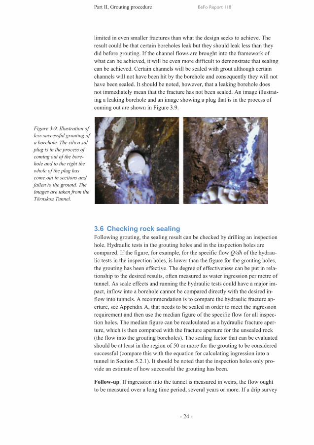
The borehole is leaking despite the fact that it has been grouted. It should be noted whether the leak is superficial or whether it is dripping from the actual borehole plug. One course of action could be to place the packer more superfi-cially or plug the hole using an appropriate grout, such as stiff cement or pol-yurethane, and using an appropriate grouting technique. The following is very important in this context. The silica sol has been chosen as a grout mainly due to the low level of ingression and thus small fracture apertures. This means that it is difficult to achieve 100% sealing as the penetration length is more
Figure 3-8. A good silica sol plug in a borehole. Image from Hallandsås.
Part II, Grouting procedure BeFo Report 118
- 24 -
limited in even smaller fractures than what the design seeks to achieve. The result could be that certain boreholes leak but they should leak less than they did before grouting. If the channel flows are brought into the framework of what can be achieved, it will be even more difficult to demonstrate that sealing can be achieved. Certain channels will be sealed with grout although certain channels will not have been hit by the borehole and consequently they will not have been sealed. It should be noted, however, that a leaking borehole does not immediately mean that the fracture has not been sealed. An image illustrat-ing a leaking borehole and an image showing a plug that is in the process of coming out are shown in Figure 3.9.
3.6 Checking rock sealing Following grouting, the sealing result can be checked by drilling an inspection hole. Hydraulic tests in the grouting holes and in the inspection holes are compared. If the figure, for example, for the specific flow Q/dh of the hydrau-lic tests in the inspection holes, is lower than the figure for the grouting holes, the grouting has been effective. The degree of effectiveness can be put in rela-tionship to the desired results, often measured as water ingression per metre of tunnel. As scale effects and running the hydraulic tests could have a major im-pact, inflow into a borehole cannot be compared directly with the desired in-flow into tunnels. A recommendation is to compare the hydraulic fracture ap-erture, see Appendix A, that needs to be sealed in order to meet the ingression requirement and then use the median figure of the specific flow for all inspec-tion holes. The median figure can be recalculated as a hydraulic fracture aper-ture, which is then compared with the fracture aperture for the unsealed rock (the flow into the grouting boreholes). The sealing factor that can be evaluated should be at least in the region of 50 or more for the grouting to be considered successful (compare this with the equation for calculating ingression into a tunnel in Section 5.2.1). It should be noted that the inspection holes only pro-vide an estimate of how successful the grouting has been.
Follow-up. If ingression into the tunnel is measured in weirs, the flow ought to be measured over a long time period, several years or more. If a drip survey
Figure 3-9. Illustration of less successful grouting of a borehole. The silica sol plug is in the process of coming out of the bore-hole and to the right the whole of the plug has come out in sections and fallen to the ground. The images are taken from the Törnskog Tunnel.

Part II, Grouting procedure BeFo Report 118
- 25 -
is conducted – to fit geomembranes for example – drip characterisation ought to be carried out several times over a long period. The weir results together with the drip survey data form a good basis for assessing the longevity of a grouting material. However, it is important that the drip survey is conducted systematically and with a time log, and that all drips are noted over a fixed section.
3.7 Development of the mixing process and equipment There is considerable potential to achieve time-efficient grouting with silica sol. The controllable gel time is a development that is very positive from a material point of view. The waste generated in conjunction with batch grout-ing is at present necessary but could very well be minimised. Linking usage to water loss could be the first step towards reducing waste.
A major development possibility is abandoning the traditional piston pumps in favour, for example, of cogwheel pumps or several piston pumps connected in parallel (similar to a high-pressure washer) that can generate stable flows and stable pressures.
One condition, however, is that controllable gel times are retained, which at present can be made possible by two pumps being connected in parallel, with one pumping silica sol and the other pumping the saline solution. Both pumps work at the same pressure and are fitted with check valves. The mixing is car-ried out at the packer nozzle with a built-in spiral or with a mechanical mixer (it is not certain whether the latter is available on the market). To obtain a con-trollable gel time, the pump for the saline solution can be fitted with a control valve that supplies a small amount of saline solution on commencement of grouting before gradually increasing (alternatively, control the salt content). The regulation of such a pump ought to reproduce the desired viscosity curve.
A process with more imminent potential is grouting using a continuous batch. Instead of pouring out the excess material from a previous grouting batch, it is mixed with a new batch – see principle in Figure 3-10. See also Appendix A. This is possible if the batch has not gelled and the remaining amount is not too large in relation to the next batch. An attentive grouter can control this process although it still requires manual weighing of the volumes. If this procedure is used, it would be advisable to permit gel times with a variation of 5 minutes (designed gel time ± 5 minutes). The grouting time is then always set accord-ing to the longest gel time. This has been tested in two projects – in the Törnskog Tunnel and in post-grouting in Gothenburg (Funehag and Gus-tafson, 2005 and Janson et al. 2010). The method was formulated during the course of the work, where at least 30% of the remaining volume could be mixed with a new batch. A proportion higher than 40% of the excess batch should not to be used as the higher viscosity of the new, combined mixture has a direct effect on the penetration length. To determine the proportion of the excess batch that can be used when it is mixed, this must be tested in the la-boratory.

Part II, Grouting procedure BeFo Report 118
- 26 -
In the case of continuous mixing, extra attention must be given to the mixing conditions and the gel times that are obtained. When the older mixture is mixed with a new mixture, this will increase the salt content or the silica sol content in the added mixture. A common occurrence is that a borehole has been grouted with a longer gel time, e.g. 38 minutes, whilst the next borehole is grouted with a gel time of 30 minutes. The normal mixing ratio is pre-set for 38 minutes and without changing the pre-set parameters the next mixture is prepared with a higher saline solution content, in this case a further 2.2 kg. If a longer gel time is desired, more silica sol is added. The table below shows four examples of such a mixture (Table 3-4). This only applies, however, when the batch has been newly mixed. If the mixture has begun to gel, it is recommended that it be discarded and the equipment cleaned.
Table 3-4. Adjustment of the mixing ratios.
Normal mixing ratio
Gel time
Target gel
time
Expected ratio
Weight ratio for a normal mixture
Weight min Min 105 kg sol 21 kg salt
5.0:1 38 30 4.5:1 - +2.2 extra
5.0:1 38 22.5 4.0:1 - +5 extra
4.0:1 30 30 4.5:1 +12.5 extra -
4.0:1 30 38 5.0:1 +25 extra -
0,00
0,50
1,00
1,50
2,00
2,50
0,0040,0060,0080,0100,0120,0140,0160,0180,020
0 500 1000 1500 2000
Visc
osity
, µ [P
as]
Time [s]
Viscosity increase and penetration length
Penetration
Viscosity
Pene
tratio
n le
ngth
[m]
Figure 3-10. Example of how the viscosity and penetration are affected when an old batch is mixed with a new batch. The un-broken line is a new mixture and the bro-ken line is an old mix-ture combined with a new batch, which re-sults in a slightly higher viscosity.

Part II, Grouting procedure BeFo Report 118
- 27 -
4 Problems and actions in conjunction with grouting
4.1 Basic impact of the rock on grouting When grouting takes place there is often one ‘problem’ or another. The nature of the problem is linked to how the rock is arranged. A common problem of-ten reported from the tunnel front is surface leakage or backflow.
When silica sol is used, surface leakage often starts as a small spray of milky liquid from the rock. Gradually, the pressure rises, increasing the volume of ingression, but falls when the silica sol begins to gel. In purely practical terms, this is considered a problem although theoretically it does not affect the result, i.e. on condition that the pressure rises and reaches the design pressure. If sur-face leakage results in a high material usage (large volumes) the grouting technique should be adjusted but only if the design pressure is not achieved or if the grouting time is not achieved before a new mixture needs to be prepared.
4.1.1. Possible reasons for dilution A problem linked to the grouting fan design is that there is water in some of the holes – the downwardly inclined boreholes.
Some of the silica sol is mixed with the water that remains in the borehole and becomes ‘slurry’. The gelled silica sol that is in contact with the slurry is slowly eroded. Gradually, the remaining gelled sol in the borehole has an in-sufficient contact surface with the rock, the shearing forces become less than the pressure exerted and result is that the gel slides out. Visually, the hole first appears to leak quite large volumes of water but as soon as the pressure falls back, this ceases and the flow reaches equilibrium.
To avoid this problem, it is important that the water in the borehole is pumped out thoroughly before grouting commences.
Another problem that could also occur in upwardly inclined holes is that the silica sol does not gel. The left-hand image in Figure 4-2 shows a reason for this.
Figure 4-1. Bore-holes directed downwards. The left-hand image shows a borehole where there is water remaining. The water is mixed with silica sol into a non-hardening ‘slur-ry’. The right-hand image shows a borehole where water is preventing a frac-ture from being sealed.

Part II, Grouting procedure BeFo Report 118
- 28 -
The problem in the left-hand image in Figure 4.2 is super-ficial fractures that cause a fall in pressure in the borehole. This can be likened to tests carried out at the Äspö Research Tunnel TASS (Funehag and Emmelin, 2010). Trapped air and water are forced out of the borehole during grouting using a hose lowered down through the packer. The idea was that the hose should allow complete filling of the borehole although the result instead was that the silica sol never hardened, which could be due to turbulent flow (the hose through the packer was in contact with atmospheric pressure) which caused a re-mixing of silica sol and inflow of water. Similarly, it could be a fracture that causes a pressure difference between the bore-hole and the tunnel. The simplest solution to this is that the packer is fitted lower down in the hole, thus bypassing the fracture that is releasing the pressure. An alternative is to re-duce the flow and the pressure to fill the borehole more slowly and then return to the design pressure.
The right-hand image shows that, despite vacuum pumping, water is still en-tering the borehole even though the borehole is upwardly inclined. During grouting, the water entering the borehole dilutes the silica sol. Generally, the volumes are only small and do not affect the result. One way of preventing borehole problems is to categorise boreholes based on anticipated problems. Boreholes that fall into this ‘multi-action’ category could be a source of con-cern in that it will take more time and certainly a higher volume of grout to rectify the problems. The table on the next page (Table 4-1) contains a pro-posal that has been tested to predict ‘problem holes’. However, it can be said that a number of the measures are already being taken automatically by the contractor and the table should be regarded more as a way of highlighting the problems facing the grouter.
Figure 4-2. Upwardly inclined boreholes. The left-hand image il-lustrates the problem of dripping boreholes in conjunction with low pumping pressure. The right-hand image shows an injected borehole with a small wedge where gelling has not taken place because of di-luted grout. Otherwise, it is a per-fect hit on a right angle fracture plane with full penetration.

Part II, Grouting procedure BeFo Report 118
- 29 -
Table 4-1. Prediction of boreholes that cause problems for the grouter.
Step 1. Categorisation of grouting boreholes
Step 2. Proposed actions
Designation Action
0) Nothing, start grouting
1) Empty the borehole by opening the packer
2) Fill the hose
3) Vacuum pumping
4) Move the packer further in
5) Mix and inject a shorter, stiffer gel time batch
6) Mix and inject a shorter, stiffer gel time batch and reduce the pressure
Step 3. Combinations of hole categories and actions
Combination Action Combination Action Combination Action
A1+B1 2 and 3 A2+B1 1 and 3 A1/A2+C1+B1 4
A1+B2 0, 2 and 3 A2+B2 1 A1/A2+C1+B2
4 and 5
A1+B3 0 and 2 A2+B3 0 A1/A2+C1+B3
4, 5 and 6
4.1.2 Evacuation of air and water from the borehole Recently, a newly developed product, based on a vacuum pump, has been used in a number of projects. The aim is to remove water and air from the borehole before grouting commences. The benefit is twofold: filling holes and raising the grouting pressure are quicker and at the same time it ensures that boreholes are filled completely with grout. The system comprises two parts: a pump with a 150-litre tank that creates a vacuum, and a valve package linked to the packer. The valve package allows a hose to be inserted down to the bot-tom of the borehole (borehole with a downward incline). The hose comes into contact with the air and the water can be sucked out through the packer into the tank. At first, the borehole is emptied of water, which takes approximately
Category A (Direction) Category B (Flow) Category C (Other)
Downward incline A 1 < 2l/min B 1 Surface leakage, low pressure
C1
Upward incline A 2 2-5 l/min B 2 Other C2
> 5 l/min B 3

Part II, Grouting procedure BeFo Report 118
- 30 -
1-2 minutes for a normal grouting hole, then the hose is removed and the borehole is put under vacuum. This could be done in a number of boreholes ahead of upcoming grouting holes.
However, the valve package is not removed until just before grouting in the borehole in question is due to commence. A borehole with an upward incline does not need to be emptied of water via the vacuum hose and should instead only be put under vacuum. The vacuum system has been used for borehole flows of less than 2 l/min.
4.2 Grouting taking into account the observations. By setting up several design windows, see Section 6.3 and Appendix A, where the design value requirement for penetration length is achieved, the most ap-propriate grouting technique for the borehole or the fan can be applied to a de-sign window. If the first grouting technique selected is not suitable, the bore-hole distance can be reduced, providing a new window for choosing a grout-ing technique. Drilling more densely does not always mean that the first fan should be drilled with more boreholes, and instead it should be supplemented with additional boreholes based on the result. In the figure below (Figure 4-3), an example is shown of how the two design windows have been set up where the associated action table (Table 4-1) is based on a number of potential ob-servations.
Figure 4-3. Basis for an action table ac-cording to Table 4-2 based on observa-tions. The dimen-sioning requirement is a specific penetra-tion length in a frac-ture with an aper-ture of 20 µm.

Part II, Grouting procedure BeFo Report 118
- 31 -
Table 4-2. Examples of actions based on observations during grouting.
Grouting step Type of grout Grouting technique If the following is noted Alternative technique
During grouting, Start position, borehole dis-tance 3.3 m
Normal gel time (TG) = 40 min
3 MPa/20 min
Does not reach the design pressure within 5 min
2.0 MPa/TG = 60 min/30 min
During grouting Above Above Surface leakage => large
volumes => unable to maintain the design
pressure or time
Reduce the pressure, quicker gel time; 2.0
MPa/TG = 20 min/10 min
During grouting Gel time reduced
to 20 min
Alternative technique
according to the above
Still large volumes and not full pressure
2.0 MPa/TG = 20 min/increase pumping
time to 15 minutes NOTE: there is a risk that
the borehole will be flushed out when the
packer is opened. Following comple-tion of grouting into the hole with large volumes, see line above
According to the above
2.0 MPa/ TG
= 20 min/15 min
The borehole is flushed out when the packer is
dismantled.
Inject again at 3 MPa/15 min
Following comple-tion of grouting
Normal TG = 40 min
3 MPa/20 min
The borehole is flushed out when the packer is
dismantled.
Inject again TG 30 min 3 MPa/20 min.
The table shows that control only covers pressure and time. What is most im-portant is that the pressure is reached and can be maintained during the fixed grouting time. Observations and actions can be summarised as:
- Design pressure not achieved. The action is taken to increase the gel time and reduce the pressure.
- Design time not achieved. The action taken is to reduce the gel time and increase the pressure.
With the above-proposed actions, the design criterion of a specific penetration length in the critical fracture aperture is always achieved. In certain cases, this results in unacceptably high use of grout and takes too long. Sometimes, pumping of the borehole needs to be completed (with the achieved time and pressure) without the design criterion being satisfied. It is important to com-municate at the workplace that the criterion has not been achieved but that a choice has been made to save time and grout.
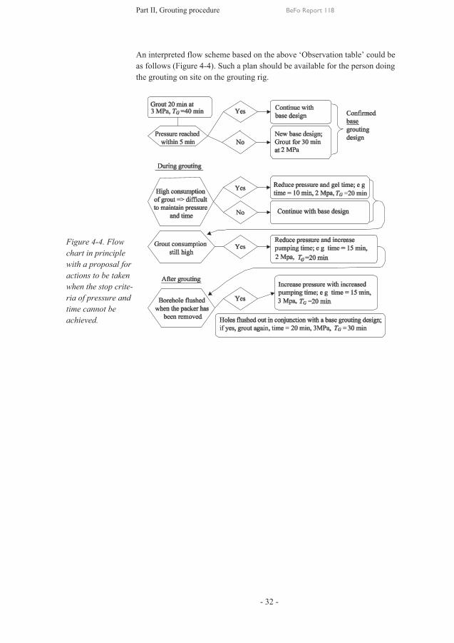
Part II, Grouting procedure BeFo Report 118
- 32 -
An interpreted flow scheme based on the above ‘Observation table’ could be as follows (Figure 4-4). Such a plan should be available for the person doing the grouting on site on the grouting rig.
Figure 4-4. Flow chart in principle with a proposal for actions to be taken when the stop crite-ria of pressure and time cannot be achieved.

Part III, Planning and design theory BeFo Report 118
- 33 -
5 Basic properties and theories
5.1 General From a grouting point of view, the fracture structures in the rock and their different properties are essential information if a good sealing result is to be achieved. A simple schematic model of a tunnel and overlying rock is shown in the figure below
On this scale, only the larger fracture structures or fracture zones are shown, which is also the focus when different grouting initiatives are de-cided. It is mostly these that are examined with the aid of boreholes in combination with hydraulic tests. From the boreholes, the fracture inten-sity and the properties of the fractures can be examined. From the hydrau-lic tests and fracture information, the water permeability of the rock mass can be calculated by measuring the transmissivity, T, and estimating the hydraulic apertures in the fractures. For a detailed description of different hydraulic tests in boreholes and an estimate of the hydraulic conductivity, reference can be made to Gustafson, (2009). A grouting design can apply to different sections of the tunnel – in sections where the expectation is that the leakage will be high because of a fracture zone, or in sections where thicker rock is expected. In summary:
1) Valid for boreholes in each grouting fan. In this case, the choice of grout and grouting technique is governed by the hydraulic tests in the holes (water loss or natural inflow). A basic assumption is needed for how the inflow from the whole of the borehole is in relation to the largest fracture. By maintaining a design where the inflow in each borehole is measured, the largest hydraulic frac-ture aperture from the borehole can be calculated. The simplest assumption is that the total inflow into the borehole comes from just one fracture.
2) Valid for a forecast part of the tunnel, typical rock/rock category, when one or several fans can be grouted according to a predeter-mined design.
Figure 5-1. Schematic profile of a tunnel, rock and overlying soil layer with the ground-water level marked.
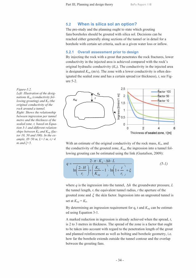
FigureLeft: Illustration of the desinations Klowing original conductivity of the rock around a tunnel.Right: between metre and the sealed zone, tion ships betweentor 10, 50 and 100). ample, m and
Figure-5.2. Left: Illustration of the desinations Kinj (conductivity folowing groutingoriginal conductivity of the rock around a tunnel.Right: Shows the relationship between ingressionmetre and the thickness of the sealed zone, t, based on tion 3-1 and different relatioships between tor 10, 50 and 100). ample, H=50 m, L=1 m, rm and ζ=5.
Left: Illustration of the desig-(conductivity fol-
grouting) and Kb (the original conductivity of the rock around a tunnel.
hows the relationship ingression per tunnel
thickness of the t, based on Equdifferent relatio Kb and Kinj (fa
tor 10, 50 and 100). In the eH=50 m, L=1 m, rt=4
Part III, Planning and design theory
5.2 The prefans/boreholes should bereached either generally along sections of the tunnel or in detail for a borehole with certain set criteria, such as a
5.2.1By injecting the rock with a groutconductivity in the injected area is achieved compared with the rockoriginal hydraulic conductivityis designated ignated the sealed zone and has a certain spread (or thickness)ure
With an the conductivity of the lowing grouting
=q
wherethe tunnel lengthgroutedset at
By determining aed using
A marked reduction inis 2 to be taken into account with regard to and how between the
g-l-
the
hows the relationship per tunnel
thickness of the Equa-
different relation-(fac-
In the ex-=4
Part III, Planning and design theory
When is silica sol an option? The pre-study and the planning ought to state which
s/boreholes should bereached either generally along sections of the tunnel or in detail for a borehole with certain set criteria, such as a
5.2.1 Overall assessment prior to y injecting the rock with a grout
conductivity in the injected area is achieved compared with the rockoriginal hydraulic conductivityis designated Kinj
ignated the sealed zone and has a certain spread (or thickness) 5-2.
With an estimate of the original conductivity of the rock massthe conductivity of the lowing grouting
÷÷ø
öççè
æ ×=
trH2ln
where q is the ingressionthe tunnel lengthgrouted zone andset at Kinj = Kb.
By determining aed using Equation
A marked reduction in2 to 3 metres in thickness. The spread of the zone is a factor that ought
to be taken into account with regard to planned reinforcement as well
how far the borehole extends between the grouting
Part III, Planning and design theory
When is silica sol an option? study and the planning ought to state which
s/boreholes should be groutedreached either generally along sections of the tunnel or in detail for a borehole with certain set criteria, such as a
Overall assessment prior to y injecting the rock with a grout
conductivity in the injected area is achieved compared with the rockoriginal hydraulic conductivity
inj (m/s). The zone with a lower conductivity is often ignated the sealed zone and has a certain spread (or thickness)
estimate of the original conductivity of the rock massthe conductivity of the groutedlowing grouting can be estimated using the link
p
÷÷ø
öççè
æ-+
D×××
inj
b
b
KK
K
1
2
ingression into the tunnelthe tunnel length, rt the equivalent tunnel radius
zone and x the skin factor.
By determining an ingressionquation 3-1.
A marked reduction in ingressionin thickness. The spread of the zone is a factor that ought
to be taken into account with regard to planned reinforcement as well
the borehole extends grouting fans.
Part III, Planning and design theory
- 34 -
When is silica sol an option? study and the planning ought to state which
grouted with silica sol. Decisions can be reached either generally along sections of the tunnel or in detail for a borehole with certain set criteria, such as a
Overall assessment prior to y injecting the rock with a grout that penetrates the rock fractures, lower
conductivity in the injected area is achieved compared with the rockoriginal hydraulic conductivity (Kb). The conductivity in the injected area
The zone with a lower conductivity is often ignated the sealed zone and has a certain spread (or thickness)
estimate of the original conductivity of the rock massgrouted zone, Kinj
can be estimated using the link
÷÷ø
öççè
æ+×÷
÷ø
ö×D
trt
Lh
1ln
into the tunnel, the equivalent tunnel radiusthe skin factor. Ingression
n ingression requirement for
ingression is already in thickness. The spread of the zone is a factor that ought
to be taken into account with regard to the planned reinforcement as well as bolting and borehole geometry, i.e.
the borehole extends outside the tunnel
BeFo Report 118
When is silica sol an option? study and the planning ought to state which
with silica sol. Decisions can be reached either generally along sections of the tunnel or in detail for a borehole with certain set criteria, such as a given water loss or inflow.
Overall assessment prior to design penetrates the rock fractures, lower
conductivity in the injected area is achieved compared with the rockThe conductivity in the injected area
The zone with a lower conductivity is often ignated the sealed zone and has a certain spread (or thickness)
estimate of the original conductivity of the rock massinj, the ingression
can be estimated using the link (Gustafson, 2009)
x+÷÷ø
ö
, hD the groundwater pressurethe equivalent tunnel radius, t the
Ingression into an un
requirement for q, t and
already achieved in thickness. The spread of the zone is a factor that ought
the penetration length of the grouts bolting and borehole geometry, i.e.
the tunnel contour and the overlap
BeFo Report 118
study and the planning ought to state which grouting with silica sol. Decisions can be
reached either generally along sections of the tunnel or in detail for a water loss or inflow.
penetrates the rock fractures, lower conductivity in the injected area is achieved compared with the rock
The conductivity in the injected area The zone with a lower conductivity is often
ignated the sealed zone and has a certain spread (or thickness), t, s
estimate of the original conductivity of the rock mass, Kb
ingression into a tunnel (Gustafson, 2009)
(5
the groundwater pressurethe aperture of the
into an ungrouted
and Kinj can be estima
achieved when the spreadin thickness. The spread of the zone is a factor that ought
penetration length of the grouts bolting and borehole geometry, i.e.
contour and the overlap
with silica sol. Decisions can be reached either generally along sections of the tunnel or in detail for a
water loss or inflow.
penetrates the rock fractures, lower conductivity in the injected area is achieved compared with the rock’s
The conductivity in the injected area The zone with a lower conductivity is often des-
, see Fig-
Kb, and into a tunnel fol-
(Gustafson, 2009):
(5-1)
the groundwater pressure, L of the
tunnel is
can be estimat-
the spread, t, in thickness. The spread of the zone is a factor that ought
penetration length of the grout s bolting and borehole geometry, i.e.
contour and the overlap

Part III, Planning and design theory BeFo Report 118
- 35 -
The level of sealing, i.e. Kinj, that can be achieved in terms of hydraulic conductivity in the grouted zone is unclear. The hydraulic conductivity of the grouted zone cannot be measured directly in the rock mass and in-stead indirect methods need to be used to estimate it. The most suitable and quickest measurement approach is hydraulic tests in boreholes. With analyses and hydraulic tests, forecasts can be made of whether the level of ingression measured at weirs can be achieved. One possibility is to set up provisional weirs as tunnel construction progresses in order to high-light the ingression at an earlier stage rather than in the final phase of construction.
Achieving a sealing factor, Kb/Kinj, of more than 50 is frequently desirable to ensure effective grouting. To assess the degree of sealing that can be achieved using a certain grout and grouting spread, specific searches have been made to draw on experience from previous groutings. Among the criteria for successful sealing, it can be stated that in many underground projects the criterion for re-grouting, i.e. a further grouting fan at the same tunnel front, is in the region of 3-5×10⁻⁸ m/s. In addition, a limit when estimating achieved sealing is linked to water loss measurements in production, where the equipment frequently has a lower measurement limit, equivalent to conductivity of approximately 1×10⁻⁸ m/s (Dalmalm et al., 2000 and Persson et al., 2009). This means that low values, approxi-mately 1×10⁻⁸ m/s, are often reported as ‘sealed holes’.
Based on experience from groutings carried out using cement in hard fractured rock, e.g. (Stille and Andersson, 2008) and (Persson et al, 2009), the assessment is that the hydraulic conductivity that can normally be achieved with cement grouting is in the region of 10-8 m/s. Lower conductivity figures, approximately 0.5·10-9 m/s, have been reported in conjunction with different grouting trials (Emmelin et al, 2004) and (Butron et al, 2008). It ought to be noted that the lower figures show ex-perience from a number of limited grouting fans during well-planned tri-als.
To achieve a higher level of sealing, trials have been conducted in recent years in Sweden using silica sol (Funehag, 2007), (Ellison, 2007) and (Butron et al, 2008). These trials have been conducted as a number of limited grouting fans in conjunction with major tunnel projects. The grouting method used in the different trials was based on the required penetration of the silica sol.
Trials with silica sol indicate that a degree of sealing by a further factor of approximately 10 in hydraulic conductivity can be achieved compared with cement grouting, i.e. hydraulic conductivity in the injected zone of approximately 1×10⁻¹⁰ m/s. An even higher degree of sealing using silica sol was achieved in a development project conducted on behalf of SKB. With two to three rounds of grouting using silica sol, a sealing level of approximately 1×10-11 m/s was achieved (Funehag and Emmelin, 2010).

Part III, Planning and design theory BeFo Report 118
- 36 -
Planning and performance, i.e. management on site, and other grouting technology, have also been of major significance to the sealing result achieved. Furthermore, the local fractured structure could have an impact to a varying degree on the final grouting outcome.
Prior to design, a general assessment must be made of the degree of grouting that is necessary. A rough assessment of the extent/degree of difficulty is shown in the diagram below (Figure 5-3) (according to Bergman and Nord, 1982). The starting point is the pre-set sealing re-quirements and an estimate of the ingression into the ungrouted tunnel. It ought to be mentioned that the projects shown in the figure were from the outset considered difficult in terms of grouting. For this reason, silica sol was used and the sealing targets sought were achieved.
5.2.2 Assessment of penetration capacity Assessment of the penetration capacity of the grout is unclear and conse-quently certain indirect methods are used to estimate it. The most com-mon methods are employed mainly in laboratories and some form of spe-cial equipment is used, see Eriksson and Stille (2005) and Draganovic (2009). In brief, the penetration capacity can be grouped into cement grouts and non-cement grouts, including silica sol.
Because of their particles, cement grouts have a limited capacity to pene-trate a certain fracture aperture. Trials have been conducted in laborato-ries to determine the critical aperture for cement grouts, see summary by, among others, (Draganovic, 2009). Trials often result in a critical aper-ture, i.e. where the main part of the grout can penetrate an aperture of 50 to 100 mm, depending, among other things, on the type of cement, the recipe, the mixture and the trial method.
Figure 5-3. Diagram to assess the extent of grout-ing based on the assessed water ingression into the tunnel and the pre-set seal-ing requirements (accord-ing to Bergman and Nord, 1982). In the figure, two tri-als are marked: the trial at Äspö in the TASS Tunnel and a 100 m section of the Törnskog Tunnel.

Part III, Planning and design theory BeFo Report 118
- 37 -
úû
ùêë
é÷÷ø
öççè
æ+
D´=ú
û
ùêë
é÷÷ø
öççè
æ+
D´=
w
tw
w
t
rL
pgQ
rL
hQT
2ln1
22ln1
2 pr
p
As mentioned previously, silica sol particles are small, i.e. approximately 1000th the size of cement particles, and it has not been possible to con-duct any direct laboratory trials in the same way as for cement grouts. In-gression tests in a number of projects have confirmed the penetration ca-pacity of silica sol down to hydraulic fracture apertures of at least 10 mm or so (Funehag, 2007).
This means that assessment of which fracture apertures need to be pene-trated to achieve the sealing objectives or equivalent is vital when decid-ing which type of grout is desirable.
5.3 The impact of the design on the fractures Geological surveys and core mapping have produced information about the fracture properties, such as length, size and frequency. With core mapping and associated hydraulic tests, the hydraulic properties of the borehole can be obtained. In the case of hydraulic tests conducted on a section basis, the transmissivity of the fractures can also be obtained. During tunnel construction, a large number of other fractures are encoun-tered, varying in length, size, orientation and water transmissivity. The fracture properties that influence grouting are the variation in fracture ap-erture, the distribution of fracture apertures, fracture filling and how the fractures are connected to each other. The orientation and number (frac-ture intensity) are also key parameters from a grouting point of view.
The significance of fractures to the design can be linked in the first in-stance to two aspects: firstly the extent to which the fracture apertures need to be sealed and, secondly, which fan geometry is appropriate com-pared with the fracture orientation.
5.3.1 Smallest design fracture aperture The smallest design fracture aperture is vital to the design as this is what determines how far the penetration needs to extend in order to meet the ingression stipulation.
The capacity of the fracture to transport water, i.e. the fracture transmis-sivity T, is proportional to the cube of the fracture aperture, i.e. hydraulic fracture aperture, bhyd, is obtained with the aid of fracture transmissivity:
312
rm´´
=g
Tbhyd
(5-2)
where µ is the viscosity, g is the earth’s acceleration and ρ is the density of the water.
Using the assumption that it is a fracture that is the primary cause of wa-ter transmission in a test section, the fracture transmissivity, T, deter-mined from the inflow tests, Q, can be set according to:
(5-3)

Part III, Planning and design theory BeFo Report 118
- 38 -
where hD is the groundwater pressure or, in the case of water loss meas-urements, pD is the exerted overpressure, Lt the section length, rw the borehole radius and ρw the density of the water.
For short tests, of short duration, the transmissivity, T, can be set as being equal to the specific capacity (Q/dh).
If several test sections with related fracture mapping have been obtained, a distribution of the fracture transmissivity and fracture apertures can be made. Gustafson (2009) and others describe how these distributions can be prepared. The individual fracture transmissivities along the borehole are used as input to prepare a pareto distribution. A pareto distribution presupposes that there is a small number of fractures with a large fracture aperture and a large number of fractures with a small fraction aperture (Gustafson and Fransson 2005). Using the distribution equation below, P(T<Tn), is calculated, i.e. the probability that the transmissivity, T, is lower than the section transmissivity, Tn.
( ) ( )1
1 max
+-=<
NTT
TTPk
nn
(5-4)
n is the number of transmissivities in sections, arranged according to size and k is a constant for the pareto distribution. N is the total number of fractures for the core borehole and Tmax is the transmissivity of the largest fracture. P(T<Tn), i.e. the probability that the section transmissivity is lower than the total transmissivity. The figures calculated are plotted on the graph using log(1-P(T<Tn)) against log(Tn). The line is adapted to these figures, the angle of which is the constant k.
The method of using the pareto distribution in a grouting design has been presented (Gustafson et al. 2004). When the distribution of the transmissivi-ties has been produced, this can be proportioned directly in a distribution of hydraulic fracture apertures using ‘cubic law’. In the figure below, an exam-ple is shown of the transmissivity distribution: Pareto distribution for fracture transmissivities (Figure 5-4).
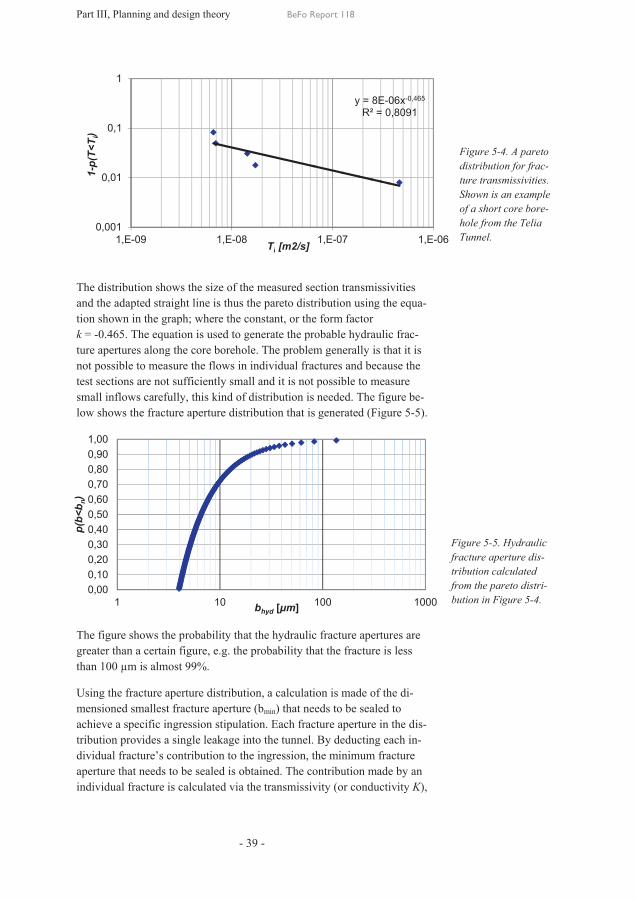
Part III, Planning and design theory BeFo Report 118
- 39 -
The distribution shows the size of the measured section transmissivities and the adapted straight line is thus the pareto distribution using the equa-tion shown in the graph; where the constant, or the form factor k = -0.465. The equation is used to generate the probable hydraulic frac-ture apertures along the core borehole. The problem generally is that it is not possible to measure the flows in individual fractures and because the test sections are not sufficiently small and it is not possible to measure small inflows carefully, this kind of distribution is needed. The figure be-low shows the fracture aperture distribution that is generated (Figure 5-5).
The figure shows the probability that the hydraulic fracture apertures are greater than a certain figure, e.g. the probability that the fracture is less than 100 µm is almost 99%.
Using the fracture aperture distribution, a calculation is made of the di-mensioned smallest fracture aperture (bmin) that needs to be sealed to achieve a specific ingression stipulation. Each fracture aperture in the dis-tribution provides a single leakage into the tunnel. By deducting each in-dividual fracture’s contribution to the ingression, the minimum fracture aperture that needs to be sealed is obtained. The contribution made by an individual fracture is calculated via the transmissivity (or conductivity K),
y = 8E-06x-0,465
R² = 0,8091
0,001
0,01
0,1
1
1,E-09 1,E-08 1,E-07 1,E-06
1-p(
T<T i
)
Ti [m2/s]
0,000,100,200,300,400,500,600,700,800,901,00
1 10 100 1000
p(b<
b n)
bhyd [μm]
Figure 5-4. A pareto distribution for frac-ture transmissivities. Shown is an example of a short core bore-hole from the Telia Tunnel.
Figure 5-5. Hydraulic fracture aperture dis-tribution calculated from the pareto distri-bution in Figure 5-4.

Part III, Planning and design theory BeFo Report 118
- 40 -
Kinj in the ingression formula (Equation 5-1). Depending on the size of the smallest dimensioned fracture aperture, the different grouts can be adapted depending on their penetration capacity. In the table below, the example from above is shown and the ingression into the tunnel is calcu-lated using Equation 5-1. The groundwater pressure, H = 35 mvp, the length, L = 100 m, equivalent tunnel radius, rt = 2.5 m, thickness of the sealed zone t = 7.5 m. Ttot = 2.4´10-6 m2/s.
Table 5-1. Example of how the fracture aperture distribution is used to calculate a design fracture aperture.
Smallest sealed frac-ture, bmin
Estimated ingression, qgrout
Tgrout Comment
[μm] [l/min×100 m] [m2/s]
None 3.8 2.4´10-6 Without grouting
136 2.9 8.2´10-7 Largest fracture sealed
34 1.0 1.3´10-7 Critical fracture aperture
As the table shows, all fractures with a hydraulic aperture down to 34 µm must be sealed to achieve the ingression requirement of 1 l/min per 100 m of tunnel. Using this approach, a robust and traceable design stipulation is achieved.
5.3.2 Fracture orientation and fan geometry In the initial phase, the fracture orientations are achieved. This is obtained from geological land surface surveys or from core boreholes. Adapting the grouting fan completely to the direction of the fractures is difficult. It is obvious, however, that the orientation is of significance to the design and that during normal pre-grouting not all fractures are hit, which is also part of the analysis in order to achieve a predictable grouting outcome. Even at this stage, an assessment can be made of the need for post-grouting.
Below, a line of argument is shown for how the fracture orientation af-fects the design. Fracture data obtained from the geological survey can be plotted in what are termed fracture roses and stereo plots. From these im-ages, the dominant fracture orientations and their angle can be deter-mined. Using this information, the geometry of the grouting fan can be placed and adjusted in such a way that it hits the fractures as optimally as possible, see Figure 5-6. To the left is typical pre-grouting (in this case from the TASS Tunnel at Äspö) and to the right post-grouting. The orien-tations of the grouting holes are marked schematically as rings in the left-hand figure to highlight the principle. The borehole can be seen as a disc if the borehole is cut at right angles to the orientation. A normal can be added to this disc. If the normal hits the fracture plane at right angles, it also hits the borehole plane at right angles. The initiated reader under-

Part III, Planning and design theory
stands that the normal to the disc is the same as the borehole orientation. The areaboreholes below an angle that deviates by a maximum of 10° from the right angle. 10° is used as an with regard to measured fractures and borehole deviation. This anacan also be used to understand which the tunnel.
Part III, Planning and design theory
stands that the normal to the disc is the same as the borehole orientation. area marked with
boreholes below an angle that deviates by a maximum of 10° from the right angle. 10° is used as an with regard to measured fractures and borehole deviation. This anacan also be used to understand which the tunnel.
Part III, Planning and design theory
stands that the normal to the disc is the same as the borehole orientation. marked with a ‘net’ is equivalent to the fractures that are hit by
boreholes below an angle that deviates by a maximum of 10° from the right angle. 10° is used as an assumedwith regard to measured fractures and borehole deviation. This anacan also be used to understand which
BeFo Report 118
- 41 -
stands that the normal to the disc is the same as the borehole orientation. is equivalent to the fractures that are hit by
boreholes below an angle that deviates by a maximum of 10° from the assumed value for incorrect readings
with regard to measured fractures and borehole deviation. This anacan also be used to understand which fractures
BeFo Report 118
stands that the normal to the disc is the same as the borehole orientation. is equivalent to the fractures that are hit by
boreholes below an angle that deviates by a maximum of 10° from the value for incorrect readings
with regard to measured fractures and borehole deviation. This anafractures can ‘leak’
BeFo Report 118
stands that the normal to the disc is the same as the borehole orientation. is equivalent to the fractures that are hit by
boreholes below an angle that deviates by a maximum of 10° from the value for incorrect readings, both
with regard to measured fractures and borehole deviation. This analysis after blasting
stands that the normal to the disc is the same as the borehole orientation. is equivalent to the fractures that are hit by
boreholes below an angle that deviates by a maximum of 10° from the both lysis
after blasting
Figure 5-6. principle, borehole orentations can be optmised against specified fracture mapping. The left-hand image is from pre-grouting and the right-hand image is from post-grouting.
6. How, in borehole ori-
entations can be opti-against specified
fracture mapping. The hand image is from grouting and the
hand image is grouting.

Part III, Planning and design theory BeFo Report 118
- 42 -
6 Grouting design with silica sol Establishing a complete grouting design is both time-consuming and can be considered difficult. Figure 6-1 below shows one of the most recently used plans in a large grouting project, the TASS Tunnel at Äspö (Fu-nehag and Emmelin, 2010). The process is seen as an iterative process when it comes to fan geometries, where several stages need to be com-pleted to achieve reasonably optimised grouting. The final design in terms of grouting technology, pressure and times is done on site in the tunnel.
Figure 6-1. A scheme for preparing a grouting design (according to Funehag and Emmelin, 2010)
6.1 General Based on a prepared geohydrological forecast for the rock, information is obtained about the sealing requirements for the tunnel and which grout ought to be most suitable for the tunnel. In the figure below, a schematic image has been drawn of the course of the grouting in conjunction with pre-grouting. Also shown are the basic principles behind the grouting technique. A grouting design can be summarised as containing the fol-lowing three fields:
Geometry/grout/technique
Hydrogeology/rock mass
Conditions
Set the maximum permitted inflow.
Carry out preliminary investi-gations.
Determine the smallest and largest hydraulic fracture ap-erture that is to be sealed.
Choose the types of grout.
Choose the fan geometry; match the grouting time and pressure against the required penetration time; take into ac-count the risk of erosion.
Complete the design by spec-ifying controls and actions.
Describe the distribution of frac-ture transmissivities.
Calculate the inflow without grouting.
Describe the fracture net-work/fracture orientation.
Describe the distribution of hy-draulic fracture apertures.
Assign a preliminary fan geometry and the extent of the sealed zone.
Existing data/facility knowledge

Part III, Planning and design theory BeFo Report 118
- 43 -
The rock – fracture apertures; smallest required fracture that needs to be sealed to meet the ingression target.
Grouting technique – grouting pressure and grouting time. Suitable equipment.
Grouting material – silica sol, initial viscosity, viscosity growth and gel time.
By calculating the smallest penetration length in the dimensioned small-est fracture aperture that needs to be sealed, a grouting design can be pro-duced for execution. According to the figure above (Figure 6-2), the pa-rameters required for a grouting design with silica sol, apart from the properties of the grout, are grouting overpressure (Δp), design smallest fracture aperture (bmin) and the c-distance between the boreholes.
6.2 Silica sol and its penetration Grouting pressure and grouting time and gel time for the grout must be adapted to ensure that a sufficient penetration length is obtained in the design smallest fracture. Adaptation is based on theoretical links, where the rheological properties are central.
6.2.1 Gel induction time and penetration length Penetration into a fracture is linked to the viscosity curve, where it can be seen that the penetration reaches almost the maximum length before the gel time has been achieved. The maximum penetration length for two-dimensional flow with silica sol, Imax, 2-D, is calculated using (Gustafson and Funehag, 2008a and 2008b).
02max, 6
45.0m
GD
ptbI D××=-
(6-1)
where b is the hydraulic fracture aperture, Δp is the exerted overpressure, tG is the gel induction time and µ0 is the initial viscosity in silica sol.
Figure 6-2. Model of how grouting works. The pene-tration takes place in all fractures that intersect the borehole. Penetration is further in the larger frac-tures and not as far in the small fractures. The di-mensioning of the penetra-tion length is done for the smallest dimensioning fracture.

Part III, Planning and design theory BeFo Report 118
- 44 -
The gel induction time is the time it takes for the initial viscosity to dou-ble.
After the gel induction time, the viscosity increase is rapid and the pene-tration capacity falls dramatically. A rule of thumb is that the gel induc-tion time is one-third of the gel time, (Funehag, 2007). The gel induction time must not be confused with the gel time. See also section 2.3.2.
In deep tunnels, approximately 150-500 m, the risk of erosion is greater and the grouting time ought to be longer than half the gel time, whilst in shallow tunnels, <100 m, and where the gradient is low, the risk of ero-sion is less and the grouting time can be set shorter, i.e. half the gel time.
The grout can flow in channels along the fracture plane, what is termed channel flow (1-D flow) or along the whole of the fracture plane, what is termed radial flow (2-D flow). Which of the two occurs depends on the fracture features. The radial penetration length is always shorter than the channel flow and when designing, radial flow ought to be assumed.
For many projects, a maximum permitted penetration length ought to be set. It should not affect, for example, nearby tunnels or objects or force the grout up to the surface. It is in the largest fracture aperture where the penetration length will be longest. This ought to be investigated as part of the project. It should be noted that a long penetration length also results in large grout volumes, which is not always necessary to ensure a suffi-ciently sealed tunnel.
The time the pressure needs to be maintained to prevent erosion of the grout is directly dependent on the gel time. The strength increase of col-loidal silica can be observed via the viscosity increase. When the viscosi-ty increases so does the strength.
6.2.2 Calculation of volume for silica sol A link for assessing the consumption of silica sol has been produced. The link has not yet been verified in the field and must therefore be used with caution, i.e. a first approximation in conjunction, for example, with esti-mating the batch volume for each grouting hole.
The link is based on the penetration length and results from water loss measurements in the borehole. All grouting holes are normally measured for loss of water before grouting. This means that following grouting of the first grouting hole in the fan, the water transmissivity in adjacent boreholes could have been affected and results from previous water loss measurements become a source of uncertainty when making volume es-timates.
The maximum grouting volume for the fracture plane can be assumed to be:

Part III, Planning and design theory BeFo Report 118
- 45 -
0
32
322max2max 64,045,0
mpp GG
Dtpb
bIbbIV ×D
××=÷øö
çèæ××=××= (6-2)
Where Imax is calculated according to Equation 6-1. If several fracture planes have been injected along the grouting hole this gives:
0
32max 64,0
mG
DtpbV ×D
××= å (6-3)
where å 3b is the sum of all fracture apertures as a cube along the grout-
ing hole.
From a water loss measurement, a flow, Qw, is obtained in conjunction with an overpressure, wpD , and the specific capacity can be determined accord-
ing to:
gpQdhQ
ww
ww r/
/D
= (6-4)
With Equations (5-2) and (5-3), and the assumption that more fracture planes are injected along a grouting hole, the following is obtained:
úû
ùêë
é÷÷ø
öççè
æ+××
D×
=úû
ùêë
é÷÷ø
öççè
æ+×
××=×=å
ww
ww
w
w
w
w
w
w
rL
pQ
rL
dhQ
gT
gb
2ln1
212
2ln1
212123
pm
prm
rm
(6-5)
By combining Equations (6-3) and (6-5), a link is obtained for volumes according to:
Gww
w
w
G
ww
wwD tQ
pp
rLtp
rL
pQV ××
×D×D
×úû
ùêë
é÷÷ø
öççè
æ+×=
×D×ú
û
ùêë
é÷÷ø
öççè
æ+××
D×
×=00
2max 2ln184,3
2ln1
21264,0
mm
pmpm
(6-6)
Assume in conjunction with normal grouting that 625/ »wrL produces:
Gww
wD tQ
ppV ×××D×D
×=0
2max 8mm
(6-7)
Equation 6-7 can be used to assess the mixing volumes based on a water loss measurement. It is very simple to include this in a spreadsheet pro-gram to produce batch sizes. This can be used for batch grouting to min-imise wastage.

Part III, Planning and design theory BeFo Report 118
- 46 -
6.3 Design The aim behind the design of silica sol grouting is to assign values for the following elements:
· Borehole geometry · Penetration length · Grouting pressure · Grouting time · Other practical restrictions
Appendix A, contains a design that follows the design process described in Section 6, Figure 6-1. The different stages, however, are not a stepped process but more of an iterative process to achieve dimensioned grouting and can be summarised in the following figure.
As an initial approximation, an estimate is made of the geometry of the grouting fan, i.e. the length and hole angles. In normal tunnelling opera-tions, the number of rock extractions and the length of the extractions are stipulated. This affects the length of the grouting hole. In critical sections, such as sections with low rock cover or where it is assumed that there are fracture zones with a strong flow and probably poor rock quality, assess-ments are often made that involve shorter rock extraction, gentler blasting and other technical solutions. In both cases, there is a spread, or exact lengths, in the grouting fans. The overlap between one grouting fan and the next is normally 4-6 m. Figure 6-4 shows how the overlap between the grouting holes and the overlap between the fans is defined.
Figure 6-3. The choice of fan geometry and grout-ing technique is made, among other things, based on practical limita-tions.

Part III, Planning and design theory
In the case of more critical to ensure the sealed fans. A special geometric study could be required for more critical setions. Other factors could also as bolt lengthrestrictions.
The overlap of the grout between two The overlap should compensate for the fracture orientationrunning atboreholes means that the penetration from one borehole overlapetration from the other borehole. This is illustrated in Figure 6Designingsign fracture The borehole distance is thus of central significance when dpenetration length will be half as long in a fracture that is half the size.
The required or desired overlap (as a decimal) and knowing the borehole distanceing the following equation
Part III, Planning and design theory
In the case of more critical to ensure the sealed zone will also be complete at the overlap between the
s. A special geometric study could be required for more critical setions. Other factors could also
length, adjacent spaces, the risk of erosion ofrestrictions.
The overlap of the grout between two The overlap should compensate for the fracture orientationrunning at a right angle to the borehole. Overlap of grout between two boreholes means that the penetration from one borehole overlapetration from the other borehole. This is illustrated in Figure 6
esigning is done to ensure that a certain overlap fracture aperture
The borehole distance is thus of central significance when dpenetration length will be half as long in a fracture that is half the size.
The required or designdesired overlap (as a decimal) and knowing the borehole distanceing the following equation
Part III, Planning and design theory
In the case of more critical sectionszone will also be complete at the overlap between the
s. A special geometric study could be required for more critical setions. Other factors could also affect
, adjacent spaces, the risk of erosion of
The overlap of the grout between two The overlap should compensate for the fracture orientation
right angle to the borehole. Overlap of grout between two boreholes means that the penetration from one borehole overlapetration from the other borehole. This is illustrated in Figure 6
is done to ensure that a certain overlap aperture. In the example in the figure below
The borehole distance is thus of central significance when dpenetration length will be half as long in a fracture that is half the size.
esign penetration lengthdesired overlap (as a decimal) and knowing the borehole distanceing the following equation:
=
BeFo Report 118
- 47 -
sections, a long overlap zone will also be complete at the overlap between the
s. A special geometric study could be required for more critical seaffect the spread of the
, adjacent spaces, the risk of erosion of
The overlap of the grout between two groutingThe overlap should compensate for the fracture orientation
right angle to the borehole. Overlap of grout between two boreholes means that the penetration from one borehole overlapetration from the other borehole. This is illustrated in Figure 6
is done to ensure that a certain overlap . In the example in the figure below
The borehole distance is thus of central significance when dpenetration length will be half as long in a fracture that is half the size.
penetration length, Idim
desired overlap (as a decimal) and knowing the borehole distance
/2 ∗ (1 +2
BeFo Report 118
, a long overlap is usedzone will also be complete at the overlap between the
s. A special geometric study could be required for more critical sethe spread of the grouted
, adjacent spaces, the risk of erosion of the grout or other
grouting holes can be estimated. The overlap should compensate for the fracture orientation
right angle to the borehole. Overlap of grout between two boreholes means that the penetration from one borehole overlapetration from the other borehole. This is illustrated in Figure 6
is done to ensure that a certain overlap is achieved in the . In the example in the figure below,
The borehole distance is thus of central significance when dpenetration length will be half as long in a fracture that is half the size.
dim is calculated by setting the desired overlap (as a decimal) and knowing the borehole distance
2)
BeFo Report 118
is used. This is done zone will also be complete at the overlap between the
s. A special geometric study could be required for more critical sec-grouted zone, such
the grout or other
s can be estimated. The overlap should compensate for the fracture orientations not always
right angle to the borehole. Overlap of grout between two boreholes means that the penetration from one borehole overlaps the peetration from the other borehole. This is illustrated in Figure 6-5 below.
is achieved in the de-, it is 50 µm.
The borehole distance is thus of central significance when designing. The penetration length will be half as long in a fracture that is half the size.
is calculated by setting the desired overlap (as a decimal) and knowing the borehole distance, d, u
. This is done zone will also be complete at the overlap between the
c-zone, such
the grout or other
s can be estimated. not always
right angle to the borehole. Overlap of grout between two pen-
below. e-
µm. . The
penetration length will be half as long in a fracture that is half the size.
is calculated by setting the us-
Figure penetration and overlapTo the leftthe fanoverlap between two The figure‘stuffing holes‘sealedthe normal in the fansufficient penetration length
Figure 6-5. A schematic illustration of the ing process and how penetration takes place in the event of an ovelap of 50% in a fracture aperture of 0.050 mm. The penetration lengths are not drawn to scale.
Figure 6-4. Definition of penetration and overlap
o the left, overlap within fan, and to the right
overlap between two figure also shows
stuffing holes’ to ensuresealed’ front hole when
the normal groutingin the fan cannot provide sufficient penetration length.
5. A schematic illustration of the grout-ing process and how penetration takes place in the event of an over-lap of 50% in a fracture aperture of 0.050 mm. The penetration lengths are not drawn to scale.
Definition of
penetration and overlap. overlap within to the right,
overlap between two fans. also shows
to ensure a when
grouting holes cannot provide
sufficient penetration

Part III, Planning and design theory BeFo Report 118
- 48 -
How the overlap contributes to the sealed zone is shown in the figure above (Figure 6-5). It is not sufficient to have an overlap between the boreholes and the zone must also be intact between the fans. With a geo-metric observation, the overlap between the fans can also be calculated and checked. If it is recommended that the overlap between grouting holes should be at least 50%, the overlap between the fans should be at least 20%. The smaller overlap can be explained by the fact that the po-tential water path is longer along a fan compared with boreholes and thus generates high resistance. This should be studied in more detail along with what is possible in practice. Experience, however, says that an over-lap between the fans of 4-5 m with an inclined 5 m has worked. In deep tunnels or in conjunction with post-grouting, there is a risk of large hy-draulic gradients, with a subsequent risk of erosion. Even in cases where the penetration length is limited (e.g. small fracture apertures, short grout-ing times, pressure too low etc.) the normal fan does not produce a sealed tunnel front, which even in these cases could lead to a risk of erosion. It is recommended that a special study be conducted to examine the risk of erosion and to find observations during tunnelling to demonstrate that there is no risk or very little risk. The basic principles behind erosion of grout can be found in Axelsson (2009). The principles were followed and applied to a tunnel at Äspö at a depth of 450 m. Reference can also be made to Funehag and Emmelin (2011).
Using Equation 3-1, the spread of the grouted zone can be estimated alt-hough a sealed zone of approximately 4-5 m is frequently a satisfactory zone spread to achieve a sufficiently sealed tunnel. The sealed zone can become the subject of design in critical sections or when optimising the fan geometry where there is good knowledge of the fracture orientation, see Figure 5-6 above.
For silica sol with penetration lengths based on the choice of pressure and grouting time, what is termed a ‘design window’ can be produced (Figure 6-6). Here the smallest design hydraulic fracture aperture, bcrit, is ex-tremely important. Based on the conceptual rock model, see Section 5.1, this fracture aperture can be produced, which means that all fracture aper-tures down to the smallest fracture aperture must be sealed in order to achieve the stipulated tunnel ingression. It is thus for this fracture aper-ture that the penetration length, I2-D is dimensioned in order for the cho-sen I to fall within the interval, Idim<I<Imax.

Part III, Planning and design theory
A number of combinations of pressure and from the above type of that shows that a pressure of 20 bar produces a penetration length of 2.5 m in a fracture erture ofhole distance of 3.3 m is sufficient. The to 20 min although in that case the pressure must be increased. The borhole distance is thus dependent on the penetration length and can be dtermined based on the mally, the borehole distance should not exceed 4that a small borehole distance, less than 2 m, could give rise to connecteding procedure
If an overlap of grout cannot be achieved in the erture with one single grouting, the solution is trounds. This could lead to a more optimised grouting second roundSuch a strategy is shown in Figure 6groutingof 0.05 mm. In a fracture of half the half the penetration is achieved etc. ther borehole is needed between the boreholes in the first ing.
There are restrictions or recommendations regarding the maximum pemitted pressure. ing of the fractures in the rock. Whether this is a problem or an advantage
Idim
Part III, Planning and design theory
number of combinations of pressure and rom the above type of
shows that a groutingpressure of 20 bar produces a penetration length of 2.5 m in a fracture
of 20 µm. Using this set of hole distance of 3.3 m is sufficient. The to 20 min although in that case the pressure must be increased. The borhole distance is thus dependent on the penetration length and can be dtermined based on the
the borehole distance should not exceed 4that a small borehole distance, less than 2 m, could give rise to connected holes, which in turn give rise to a more time
procedure.
f an overlap of grout cannot be achieved in the with one single grouting, the solution is t. This could lead to a more optimised grouting round could be
Such a strategy is shown in Figure 6grouting round, the groutingof 0.05 mm. In a fracture of half the half the penetration is achieved etc. ther borehole is needed between the boreholes in the first
There are restrictions or recommendations regarding the maximum pemitted pressure. These are based on the risk of hydraulic jacking or opeing of the fractures in the rock. Whether this is a problem or an advantage
dim
Part III, Planning and design theory
number of combinations of pressure and rom the above type of graph. In the figure, there is a broken blue line
grouting time of 30 min (60 min gel time) at an ovepressure of 20 bar produces a penetration length of 2.5 m in a fracture
Using this set of hole distance of 3.3 m is sufficient. The to 20 min although in that case the pressure must be increased. The borhole distance is thus dependent on the penetration length and can be dtermined based on the grouting pr
the borehole distance should not exceed 4that a small borehole distance, less than 2 m, could give rise to
holes, which in turn give rise to a more time
f an overlap of grout cannot be achieved in the with one single grouting, the solution is t. This could lead to a more optimised grouting
could be needs-based (based on a number of observations). Such a strategy is shown in Figure 6
grouting is overlapped in of 0.05 mm. In a fracture of half the half the penetration is achieved etc. ther borehole is needed between the boreholes in the first
There are restrictions or recommendations regarding the maximum peThese are based on the risk of hydraulic jacking or ope
ing of the fractures in the rock. Whether this is a problem or an advantage
BeFo Report 118
- 49 -
number of combinations of pressure and grouting. In the figure, there is a broken blue line
time of 30 min (60 min gel time) at an ovepressure of 20 bar produces a penetration length of 2.5 m in a fracture
Using this set of grouting pressures and timehole distance of 3.3 m is sufficient. The groutingto 20 min although in that case the pressure must be increased. The borhole distance is thus dependent on the penetration length and can be d
pressure and gel time for silica sol. Nothe borehole distance should not exceed 4
that a small borehole distance, less than 2 m, could give rise to holes, which in turn give rise to a more time
f an overlap of grout cannot be achieved in the with one single grouting, the solution is t. This could lead to a more optimised grouting
based (based on a number of observations). Such a strategy is shown in Figure 6-8. The figure shows that for the first
is overlapped in of 0.05 mm. In a fracture of half the aperture half the penetration is achieved etc. For these fracturesther borehole is needed between the boreholes in the first
There are restrictions or recommendations regarding the maximum peThese are based on the risk of hydraulic jacking or ope
ing of the fractures in the rock. Whether this is a problem or an advantage
BeFo Report 118
grouting time can be produced. In the figure, there is a broken blue line
time of 30 min (60 min gel time) at an ovepressure of 20 bar produces a penetration length of 2.5 m in a fracture
pressures and timegrouting time can also be reduced
to 20 min although in that case the pressure must be increased. The borhole distance is thus dependent on the penetration length and can be d
essure and gel time for silica sol. Nothe borehole distance should not exceed 4-5 m at the same time
that a small borehole distance, less than 2 m, could give rise to holes, which in turn give rise to a more time-consuming
f an overlap of grout cannot be achieved in the dimensionedwith one single grouting, the solution is two or even three grouting. This could lead to a more optimised grouting strategy
based (based on a number of observations). 8. The figure shows that for the first
is overlapped in a fracture with an aperture (0.025 mm)
these fractures to be sealedther borehole is needed between the boreholes in the first
There are restrictions or recommendations regarding the maximum peThese are based on the risk of hydraulic jacking or ope
ing of the fractures in the rock. Whether this is a problem or an advantage
BeFo Report 118
time can be produced. In the figure, there is a broken blue line
time of 30 min (60 min gel time) at an over-pressure of 20 bar produces a penetration length of 2.5 m in a fracture
pressures and times, a bore-time can also be reduced
to 20 min although in that case the pressure must be increased. The borhole distance is thus dependent on the penetration length and can be d
essure and gel time for silica sol. No5 m at the same time
that a small borehole distance, less than 2 m, could give rise to numerousconsuming grou
dimensioned fracture o or even three grouting
strategy where the based (based on a number of observations).
8. The figure shows that for the first fracture with an aperture
, approximately to be sealed, a fu
ther borehole is needed between the boreholes in the first round of grou
There are restrictions or recommendations regarding the maximum peThese are based on the risk of hydraulic jacking or ope
ing of the fractures in the rock. Whether this is a problem or an advantage
time can be produced . In the figure, there is a broken blue line
r-pressure of 20 bar produces a penetration length of 2.5 m in a fracture ap-
e-time can also be reduced
to 20 min although in that case the pressure must be increased. The bore-hole distance is thus dependent on the penetration length and can be de-
essure and gel time for silica sol. Nor-5 m at the same time
numerous grout-
fracture ap-o or even three grouting
where the based (based on a number of observations).
8. The figure shows that for the first fracture with an aperture
approximately , a fur-
round of grout-
There are restrictions or recommendations regarding the maximum per-These are based on the risk of hydraulic jacking or open-
ing of the fractures in the rock. Whether this is a problem or an advantage
Figure 6tration length, Iwith a hydraulic µm, has a function of different combinations of grouting ovepressure and gel time; gel time ≈ 3* figure, 20 µm is the dimensioing fracture theoretically required penetrtion length is 2.25 m. The condtion for the penetration satisfied for combinations of gel inductionwithin the green, what is termed the design window. comparison between the borhole distance and the penetrtion length and between the gel time shown
Figure 6-6. The maximum pentration length, I2-Dwith a hydraulic aperture
has a function of different combinations of grouting ovepressure and gel time; gel time ≈ 3* gel induction time). figure, 20 µm is the dimensioing fracture aperturetheoretically required penetrtion length is 2.25 m. The condtion for the penetration satisfied for combinations of gel
duction time and pressure within the area marked in green, what is termed the design window. On the outer axes, thcomparison between the borhole distance and the penetrtion length and between the gel time and the groutingshown.
6. The maximum pene-D, in a fracture aperture of 20
has a function of different combinations of grouting over-pressure and gel time; gel time
gel induction time). (In the figure, 20 µm is the dimension-
aperture and the theoretically required penetra-tion length is 2.25 m. The condi-tion for the penetration length issatisfied for combinations of gel
time and pressure area marked in
green, what is termed the design On the outer axes, the
comparison between the bore-hole distance and the penetra-tion length and between the gel
grouting time is
e-, in a fracture
of 20
pressure and gel time; gel time (In the
i-length is
satisfied for combinations of gel
green, what is termed the design e
tion length and between the gel

Part III, Planning and design theory BeFo Report 118
- 50 -
is still a subject of debate. Whatever the case, all the pressurised compo-nents must meet a set pressure with a certain margin of safety.
The gel time at a given viscosity affects how long grouting should take . If grouting is discontinued early, when the viscosity is still low, there is a risk that water will begin to seep into the gel (water penetrates into the gel in a finger-like fashion). This is of particular importance in the event of high groundwater pressure. In Funehag (2007), there is a simple de-scription of how the gel time is related to the grouting time and the de-sired penetration length in the fracture. If the relationships presented in Section 6.2 are used during grouting, it will be understood that the gel time is an important factor for successful grouting. The table below can be used as a starting point when designing. The figures given are taken from the design window in Figure 6-9 above. After the figures have been obtained for each design step, optimisation can take place.
Design step Estimate/Choice Provides infor-mation for
Checks
Minimum fracture aperture 20 µm Penetration length
Permitted ingression
Borehole distance c. 3 m Penetration length
Necessary theoretical overlap, hits the ‘right’ fractures
Necessary penetration length in the smallest frac-ture aperture
0.75 x c-distance = 2.25 m for a 50% overlap
Grouting pressure and grouting time
Maximum permitted grouting pressure
Grouting pressure >2 x groundwater pres-sure = 20 bar
Stop criterion
Injection time At least half the gel time = 30 min
Gel time, stop cri-terion
Risk of erosion results in a longer grouting time
Gel time 2 x grouting time = 60 min
Is it reasonable?
Stop criterion 1 Predetermined grouting time at a constant pres-sure = 30 min at 20 bar
Choose the type of observations for a possible change in the stop criterion
Stop criterion 2 A certain maximum volume
Change in the cri-terion for I.
The design needs to be redone
Part III, Planning and design theory BeFo Report 118
- 51 -
7 References Andersson, H, 1998: Chemical Rock Grouting, an Experimental Study on Polyurethane Foams. Doctoral Thesis. Department of Geotechnical Engi-neering, Chalmers University of Technology, Gothenburg, Sweden.
Axelsson, M, 2006. Mechanical tests on a new non-cementitious grout, silica sol: A laboratory study of the material characteristics. Tunnelling and Underground Space Technology, vol. 21, pp 554-600. Elsevier.
Axelsson, M, 2009. Prevention of Erosion of Fresh Grout in Hard Rock. PhD thesis. New series 2915. Chalmers University of Technology.
Axelsson, M, Nilsson J, 2002. Sealing of narrow fractures in rock with use of silica sol. An introductory study on material characteristic and be-haviour as a grout. Master’s thesis. Chalmers University of Technology, Division of Civil and Environmental Engineering, Publ B 494. Gothen-burg, Sweden
Bergman, S G A, Nord, G, 1982. Täta tunnlar lagom. BeFo nr 64:1/82. Stiftelsen bergteknisk forskning, Stockholm, Sweden.
Butron, C, Axelsson, M, Gustafson, G. 2007. Silica Sol for Rock Grout-ing - Tests on Mechanical properties. Chalmers University of Technolo-gy, Division of Civil and Environmental Engineering, Report 2007:6. Gothenburg, Sweden.
Butron, C, Gustafson, G, Funehag, J, 2008. Grouting in the Nygård Tun-nel – Pre-grouting design for drip sealing and evaluation. Report 2008:2. Division of Civil and Environmental Engineering, Chalmers University of Technology.
Dalmalm T, Eriksson M, Janson T, Brantberger M, Slunga A, Dehlin P, Stille H (2000): Injekteringsförsök vid Södra Länkens bergtunnlar. Rapport 3075, Avd för Jord- and Bergmekanik, KTH, Stockholm.
Draganovic, A, 2009. Bleeding and filtration of cementitious grout. PhD thesis. Department of Soil and Rock Mechanics, Royal Institute of Tech-nology. Stockholm.
Ellison, T, 2007. Erfarenheter av injektering med silika sol, Törnskogstunneln. BK 2007. Bergsprängningskommittens 52:a möte. Stockholm.
Emmelin A, Eriksson M, Fransson Å (2004): Characterisation, design and execution of two grouting fans at 450 m level, Äspö HRL. SKB R-04-58, SKB AB
Eriksson M, Stille, H (2005): Cementinjektering i hårt berg, Rapport K22 SveBeFo
Funehag, J, Gustafson, G, 2005. Grouting with silica sol in the Törnskog Tunnel - Grouting design for silica sol in full production. Report 2005:12.
Part III, Planning and design theory BeFo Report 118
- 52 -
Division of Civil and Environmental Engineering, Chalmers University of Technology.
Funehag, J, 2007. Grouting of Fractured Rock with Silica Sol Grouting design based on penetration length. Dissertation, PhD thesis. New series 2560. Division of Civil and Environmental Engineering, Chalmers Uni-versity of Technology.
Funehag, J, Emmelin, A, 2010: Injekteringen av TASS-tunneln, Design, genomförande and resultat från förinjekteringen. SKB-rapport R-10-39. Svensk Kärnbränslehantering AB, Stockholm.
Gustafson, G, Fransson Å, Funehag, J, Axelsson, M, 2004. Ett nytt an-greppssätt för bergbeskrivning and analysprocess för injektering. Väg- and vattenbyggaren 4, 2004.
Gustafson, G, Funehag, J, 2008a. Design of grouting with silica sol in hard rock - New methods for calculation of penetration length, Part I. Tunnelling and Underground Space Technology, 23 (2008) (1) pp 1-8.
Gustafson, G, Funehag, J, 2008b. Design of grouting with silica sol in hard rock - New design criteria tested in the field, Part II. Tunnelling and Underground Space Technology, 23 (2008) (1) pp 9-17.
Gustafson, G, Fransson, Å, 2005. The use of the Pareto distribution for fracture transmissivity assessment. Hydrogeology Journal, 1435-0157.
Gustafson, G, 2009. Hydrogeologi för bergbyggare. T2:2009. Forsk-ningsrådet Formas.
Iler, R K, 1979: The Chemistry of Silica. John Wiley & Sons, USA.
Janson, T, Funehag, J, Granberg, G, Jonsson, H, 2010. Underhållstätning av mediatunnel i Göteborg- design and utförande av efterinjektering. Be-Fo rapport 105. Stiftelsen bergteknisk forskning. Stockholm.
Persoff, P, Apps, J, Moridis, G, Whang, J M, 1999: Effect of Dilution and Contaminants on Sand Grouted with Colloidal Silica. Journal of Ge-otechnical and Geoenvironmental Engineering. ASCE. Vol. 125. No. 6, June, pp. 461 - 469.
Persson K., Engström A., Gustafson G. (2009): Nyttan av vattenförlust-mätningar av tätning av tunnlar. Bergmekanikdagen 2009.
Stille, B, Andersson, F, 2008. Injektering – tillämpning av injekteringsprocessen I fält. SveBeFo rapport 79. Stiftelsen bergteknisk forskning Stockholm.
Yonekura, R, 1997: The developing process and the new concepts of chemical grout in Japan. Grouting and Deep Mixing. Proceedings of the 2nd International Conference on Ground Improvement Geosystems, To-kyo, 1996, pp. 889-901.

Appendix A Design assignment BeFo Report 118
- 53 -
General A tunnel is planned to be built in crystalline rock with an overlying soil layer comprising clay and to a certain extent friction material. The groundwater level follows the land surface almost exactly. Along the en-visaged route of the tunnel it is probable that large fracture zones will be encountered with poor rock quality and powerful water transmitting structures.
Available data
- Groundwater levels in hollows - Drill cores - Fracture mapping - Hydraulic tests in the core-drilled holes - Engineer's forecast for the facility
The drill cores are drilled from the surface at an angle of 60° in order to hit the anticipated fracture zones. The cores reach down and under the envisaged tunnel bottom, see schematic figure below. Further cores have been bored at each of the tunnel openings.
Figure 7-1. A schematic pro-file of the tunnel, rock and overlying soil layer with the groundwater level marked.
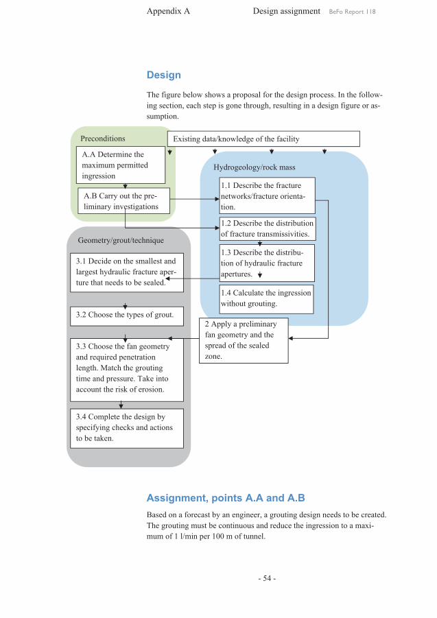
Appendix A Design assignment BeFo Report 118
- 54 -
Preconditions
Hydrogeology/rock mass
Geometry/grout/technique
A.A Determine the maximum permitted ingression
A.B Carry out the pre-liminary investigations
3.1 Decide on the smallest and largest hydraulic fracture aper-ture that needs to be sealed.
3.2 Choose the types of grout.
3.3 Choose the fan geometry and required penetration length. Match the grouting time and pressure. Take into account the risk of erosion.
3.4 Complete the design by specifying checks and actions to be taken.
1.2 Describe the distribution of fracture transmissivities.
1.4 Calculate the ingression without grouting.
1.1 Describe the fracture networks/fracture orienta-tion.
1.3 Describe the distribu-tion of hydraulic fracture apertures.
2 Apply a preliminary fan geometry and the spread of the sealed zone.
Existing data/knowledge of the facility
Design
The figure below shows a proposal for the design process. In the follow-ing section, each step is gone through, resulting in a design figure or as-sumption.
Assignment, points A.A and A.B Based on a forecast by an engineer, a grouting design needs to be created. The grouting must be continuous and reduce the ingression to a maxi-mum of 1 l/min per 100 m of tunnel.
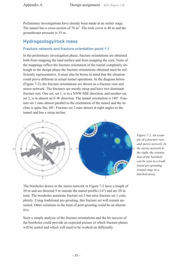
Appendix
Preliminary The tunnel has a crossgroundwater pressure is
Hydrogeology/rock mass Fracture network and fracture orientation point
In the preliminary both from the mappingshough inficiently representativecould prove(Figure 7stereo network. The fractures arefracture sets. One set 2, is in almost ature set 1cline is quite flat, 60°. Fracture set tunnel and has a steep incline.
The boreholes drawn in the stereo network20 m and total. The boreholes penetrate fracture set pletely. Using traditional presealed. Other solutions in the form of posttive.
Such a simple analysis of the fracture orientations and the hit success of the boreholes could provide an expected picture of which fracture plawill be sealed and which
Appendix A
Preliminary investigations The tunnel has a crossgroundwater pressure is
Hydrogeology/rock mass Fracture network and fracture orientation point
the preliminary investigationboth from mapping the land surface and from
mappings reflect in the design phase the fracture orientations obtained must be
ficiently representativecould prove different in(Figure 7-2), the fracture orientations are shown as a fracture stereo network. The fractures arefracture sets. One set
in almost an 1 runs almost parallel to the orientation of the tunnel and the i
cline is quite flat, 60°. Fracture set tunnel and has a steep incline.
The boreholes drawn in the stereo networkand are directed
total. The boreholes penetrate fracture set pletely. Using traditional presealed. Other solutions in the form of post
Such a simple analysis of the fracture orientations and the hit success of boreholes could provide an expected picture of which fracture pla
will be sealed and which
Design assignment
investigations have already been made at an earlier stage. The tunnel has a cross-section ofgroundwater pressure is 35 m.
Hydrogeology/rock mass Fracture network and fracture orientation point
investigation phase, fracture orientations are obtainthe land surface and from
reflect the fracture orientation the design phase the fracture orientations obtained must be
ficiently representative. It must also be borne in mind different in actual tunnel operation
2), the fracture orientations are shown as a fracture stereo network. The fractures are
set, set 1, is in a E-W direction
runs almost parallel to the orientation of the tunnel and the icline is quite flat, 60°. Fracture set tunnel and has a steep incline.
The boreholes drawn in the stereo networkare directed 5 m outside the tunnel profile
total. The boreholes penetrate fracture set pletely. Using traditional pre-groutingsealed. Other solutions in the form of post
Such a simple analysis of the fracture orientations and the hit success of boreholes could provide an expected picture of which fracture pla
will be sealed and which will need to be
Design assignment
- 55 -
already been made at an earlier stage. section of 76 m2. The r
Hydrogeology/rock mass Fracture network and fracture orientation point
phase, fracture orientations are obtainthe land surface and from
fracture orientation ofthe design phase the fracture orientations obtained must be
. It must also be borne in mind tunnel operation
2), the fracture orientations are shown as a fracture stereo network. The fractures are mostly steep
is in a NNW-SSEW direction. The tunnel orientation is 140°. Fra
runs almost parallel to the orientation of the tunnel and the icline is quite flat, 60°. Fracture set 2 runs almost
The boreholes drawn in the stereo network inoutside the tunnel profile
total. The boreholes penetrate fracture set 2 but grouting, this fracture set will remain u
sealed. Other solutions in the form of post-grouting could be a
Such a simple analysis of the fracture orientations and the hit success of boreholes could provide an expected picture of which fracture pla
will need to be worked on different
Design assignment BeFo Report 118
already been made at an earlier stage. The rock cover is 40 m and the
Fracture network and fracture orientation point 1.1
phase, fracture orientations are obtainthe land surface and from mapping the core. None of
of the tunnel completely the design phase the fracture orientations obtained must be
. It must also be borne in mind thattunnel operations. In the diagram below
2), the fracture orientations are shown as a fracture steep and have two dominant
E direction, and another setThe tunnel orientation is 140°. Fra
runs almost parallel to the orientation of the tunnel and the iruns almost at right angles to the
in Figure 7-2 have outside the tunnel profile (14°)
but miss fracture set this fracture set will remain u
grouting could be a
Such a simple analysis of the fracture orientations and the hit success of boreholes could provide an expected picture of which fracture pla
worked on different
BeFo Report 118
already been made at an earlier stage. ock cover is 40 m and the
1.1
phase, fracture orientations are obtainthe core. None of
the tunnel completely the design phase the fracture orientations obtained must be su
that the situation. In the diagram below
2), the fracture orientations are shown as a fracture rose and and have two dominant
and another setThe tunnel orientation is 140°. Fra
runs almost parallel to the orientation of the tunnel and the iright angles to the
have a length of (14°) and are 20 in
iss fracture set 1 com-this fracture set will remain un-
grouting could be an altern
Such a simple analysis of the fracture orientations and the hit success of boreholes could provide an expected picture of which fracture pla
worked on differently.
BeFo Report 118
Figure 7ple of a fracture and stereo network. In the stereo nthe right,tion of the borehole can be seen in a tradtional pre(round rings in a hatched area).
already been made at an earlier stage. ock cover is 40 m and the
phase, fracture orientations are obtained the core. None of
the tunnel completely alt-suf-
the situation . In the diagram below
and and have two dominant
and another set, The tunnel orientation is 140°. Frac-
runs almost parallel to the orientation of the tunnel and the in-right angles to the
length of 20 in
m-n-
n alterna-
Such a simple analysis of the fracture orientations and the hit success of boreholes could provide an expected picture of which fracture planes
Figure 7-2. An exaple of a fracture and stereo network. In the stereo network to the right, the orienttion of the borehole can be seen in a tradtional pre-grouting (round rings in a hatched area).
2. An exam-ple of a fracture rose and stereo network. In
etwork to the orienta-
tion of the borehole can be seen in a tradi-
grouting (round rings in a

Appendix A Design assignment BeFo Report 118
- 56 -
Transmissivity distribution, 1.2
The number of fractures per metre is obtained (fracture frequency) for core-drilled holes and the core mapping, as well as an interpretation of whether the fractures are open or closed. In the core-drilled hole, water loss measurement has been carried out, which gives the water loss in l/min, at a certain overpressure, per section of borehole in metres. By linking fractures and water loss, an assessment can be made of the per-meability and ingression into the tunnel can thus be assessed.
The following has been assumed
- KBH1 is represented by the poorer rock quality along the route of the tunnel.
- The fractures along the core-drilled hole are assumed to be two-dimensional and parallel plane structures (they do not intersect each other near the borehole).
- The surveyed open fractures contribute to the ingression into the tunnel.
- The sum of the individual ingressions is the same as the ingres-sion for the whole borehole.
The transmissivity, T, can be calculated using the Moyes formula for a section test:
=×
1 +×
Where Q is the achieved flow, dh is the overpressure used, L is the tested section length, and rw is the borehole radius.
A typical data summary from the core mapping and the water loss meas-urement are shown in the following table.
Section number
Section borehole Measured flow, Q Number of open frac-tures
T using the Moyes formula
i From [m]
To [m] [l/min] [m3/s] ni [m2/s]
1 1.5 3 0.019 3.2x10⁻⁷ 14 6.9x10⁻⁹ 2 3 6 0.047 7.8x10⁻⁷ 33 1.7x10⁻⁸ 3 6 9 0.039 6.5x10⁻⁷ 26 1.4x10⁻⁹ 4 9 12 0.018 3.0x10⁻⁷ 22 6.6x10⁻⁹ 5 12 15 1.26 2.1x10⁻⁵ 29 4.6x10⁻⁷ 6 15 18 5.17 8.6x10⁻⁵ 14 1.9x10⁻⁶
We can see from the table that there are a relatively large number of open fractures, 6-10 fractures per metre, although the measured flows are small. In this example, the groundwater pressure is 35 mvp.

Appendix A Design assignment BeFo Report 118
- 57 -
Based on the transmissivities above, a distribution is prepared known as a pareto distribution (Figure 7-3).
Above an interval from approximately 5x10⁻⁹ m2/s to 5x10⁻⁷ m2/s, the transmissivities follow almost a horizontal line in a log-log graph.
Fracture distribution 1.3
The fracture aperture is a central parameter when designing the grouting. Using figures for the fracture apertures, a penetration length can be calcu-lated and in doing so the execution can be determined. The best estimate of fracture apertures for grouting design is the hydraulic fracture aperture. The link between transmissivity and hydraulic fracture aperture is estab-lished using ‘cubic law’. With the previously prepared transmissivity dis-tribution, the distribution can generate an individual transmissivity for each open fracture. A hydraulic fracture aperture can then be calculated based on the individual transmissivities (Figure 7-4).
y = 8E-06x-0,465
R² = 0,8091
0,001
0,01
0,1
1
1,E-09 1,E-08 1,E-07 1,E-06
1-p(
T<T i
)
Ti [m2/s]
0,00
0,10
0,20
0,30
0,40
0,50
0,60
0,70
0,80
0,90
1,00
1 10 100 1000
p(b<
b n)
bhyd [μm]
Figure 7-3. A pareto distribution for the measured transmis-sivities
Figure 7-4. Hydrau-lic fracture aperture distribution is calcu-lated from the pareto distribution in Figure 7-3.

Appendix A Design assignment BeFo Report 118
- 58 -
The hydraulic fracture aperture distribution shows that the probability that there is a fracture with a hydraulic fracture aperture greater than 100 µm is very small (0.2%). It does show, however, that there are a large number of fractures with small apertures.
Ingression into an ungrouted tunnel 1.4
Ingression into the tunnel per metre (specific flow) q without grouting is calculated using (Gustafson, 2009):
[ ]x
p
+÷÷ø
öççè
æ ×
×××=
t
b
rH
HLTmsmq2ln
/2//3
where hD is the groundwater pressure, L is the section length for which the transmissivity, Tb has been calculated, H is the depth to the tunnel from the groundwater level, rt is the equivalent tunnel radius, and x is the skin factor.
With the following data entered into the equation, the ingression is calcu-lated as
Tb [m2/s]
L [m]
H [m]
rt [m]
x q ungrout-ed [m3/s/m]
Q for 100 m of ungrouted tunnel [l/min]
2.4·10-6 100 35 2.5 5 => 6.3·10-7 3.8
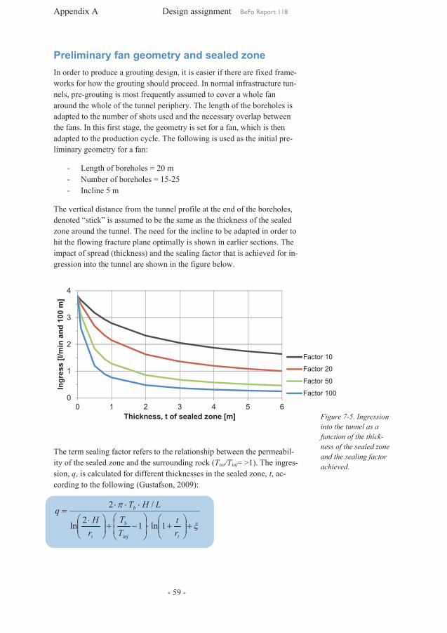
Appendix A Design assignment BeFo Report 118
- 59 -
0
1
2
3
4
0 1 2 3 4 5 6
Ingr
ess
[l/m
in a
nd 1
00 m
]
Thickness, t of sealed zone [m]
Factor 10
Factor 20
Factor 50
Factor 100
Preliminary fan geometry and sealed zone In order to produce a grouting design, it is easier if there are fixed frame-works for how the grouting should proceed. In normal infrastructure tun-nels, pre-grouting is most frequently assumed to cover a whole fan around the whole of the tunnel periphery. The length of the boreholes is adapted to the number of shots used and the necessary overlap between the fans. In this first stage, the geometry is set for a fan, which is then adapted to the production cycle. The following is used as the initial pre-liminary geometry for a fan:
- Length of boreholes = 20 m - Number of boreholes = 15-25 - Incline 5 m
The vertical distance from the tunnel profile at the end of the boreholes, denoted “stick” is assumed to be the same as the thickness of the sealed zone around the tunnel. The need for the incline to be adapted in order to hit the flowing fracture plane optimally is shown in earlier sections. The impact of spread (thickness) and the sealing factor that is achieved for in-gression into the tunnel are shown in the figure below.
The term sealing factor refers to the relationship between the permeabil-ity of the sealed zone and the surrounding rock (Ttot/Tinj= >1). The ingres-sion, q, is calculated for different thicknesses in the sealed zone, t, ac-cording to the following (Gustafson, 2009):
x
p
+÷÷ø
öççè
æ+×÷
÷ø
öççè
æ-+÷÷
ø
öççè
æ ×
×××=
tinj
b
t
b
rt
TT
rH
LHTq
1ln12ln
/2
Figure 7-5. Ingression into the tunnel as a function of the thick-ness of the sealed zone and the sealing factor achieved.

Appendix A Design assignment BeFo Report 118
- 60 -
As Figure 7-5 shows, a penetration of 2 m is sufficient along with a seal-ing factor of 50 to meet the ingression requirement of 1 l/min per 100 m of tunnel. Earlier analyses of the borehole direction in relation to the frac-ture orientations showed that penetration of at least 5 m would be suita-ble. Shorter penetration would mean that fewer planes would be hit. Penetration of 5 m and a sealing factor of at least 50 would produce an ingression of approximately 0.5 l/min. The knowledge that we did not hit one of the dominating fracture sets/fracture groups, means that the pre-liminary choice of geometry is retained. It should be borne in mind that the sealing factor is not a design parameter in this case and only provides an indication of what can be achieved.
Geometry, grout and technique Smallest and largest hydraulic fracture aperture 3.1
With the aid of the hydraulic fracture distribution in Figure 7-4, a small-est fracture aperture can be determined. The design fracture aperture must concur with the ingression requirement, i.e. all fractures down to the frac-ture aperture must be sealed.
Assuming that all open fractures are flowing, the contribution of each frac-ture to the ingression can thus be calculated. For each sealed fracture, the total of the contributions from the unsealed fractures can be calculated ac-cording to the ingression formula above. Using such a procedure, the fol-lowing is obtained (Table 7-1).
Table 7-1. Estimated ingression without grouting, where the largest frac-ture aperture is sealed, and which fracture aperture (design fracture ap-erture) needs to be sealed to meet the ingression requirement.
bmin Estimated in-gression, qgrout
Tgrout Comment
[μm] [l/min×100 m] [m2/s]
None 3.8 2.4´10-6 Without grouting
136 2.9 8.2´10-7 Largest fracture
sealed
34 1.0 1.3´10-7 Critical fracture
aperture
The relationship between transmissivity for ungrouted rock and a sealed zone is in this case only a factor of 20.
As shown in the table, all fractures with a hydraulic aperture down to 34 µm must be sealed to meet the ingression requirement of 1 l/min per 100

Appendix A Design assignment BeFo Report 118
- 61 -
m of tunnel. This approach provides a robust and traceable design re-quirement.
Summary of design requirements:
- The design fracture aperture is 34 µm. - The largest assumed fracture aperture is 136 µm
Grout, 3.2
The flows encountered during core drilling were small. The interpreted hydraulic fracture aperture that needs to be sealed ranges from 34 to 136 µm.
Cement contains particles and its penetration capacity is limited by these particles. A theoretical approach shows that particles can penetrate into columns that are 3xd95 (mesh aperture where 95% pass during one siev-ing). For normal cement, d95 could be in the size range 16-30 µm. This is equivalent to column apertures of 50-100 µm, which is thus the smallest aperture the cement can penetrate and seal. As the aim is to seal a large number of small fractures, silica sol is selected as the only ordinary grout.
Hydraulic tests should be used to check if the flows can be greater than those expected. If higher flows are found, these boreholes should be grouted with cement. Cement must thus be available at the workplace.
Summary of grouts:
- Silica sol as an ordinary grout - Cement in the case of larger flows and larger interpreted hydraulic
fracture apertures
Fan geometry and the required penetration length 3.3
Determining the smallest required penetration length is an iterative pro-cess, where the starting point is either a specified geometry (the distance between the boreholes) or a desired penetration length, and the distance between the boreholes is determined accordingly.
Fan geometry
Below, the starting point is the assumption that the fan geometry has been set (Figure 7-6).

Figure 7viewed from above. penetration is 5 m, which produces 18 boreholes with a distance between each hole of 3.5 m.
Figure 7of the overlap, 50% btween two boreholes in rlation to the fracture ture.
Figure 7-6. Fan layout viewed from above. penetration is 5 m, which produces 18 boreholes with a distance between each hole of 3.5 m.
Figure 7-7. Demonstration of the overlap, 50% be-tween two boreholes in rlation to the fracture ape
Appendix
Required penetration length
The required penetration length in the determined by the borehole distance and the undulating appearance of the fracturesplace is termed an overlap is made between the boreholes. One recommendtion used in many tween the
The r
Wherelap that has been set in 50%,
layout viewed from above. The penetration is 5 m, which produces 18 boreholes with a distance between
7. Demonstration e-
tween two boreholes in re-aper-
Geometrical data for the grouting fan:
Bore hole length= 20 mStick= 5 mDistance between boreholes at tip= 3.5 mNumber of boreholes= 18Distance between at start= 1.7 m
Appendix A
Required penetration length
he required penetration length in the determined by the borehole distance and the undulating appearance of the fracturesplace at right angles between the boreholes. To compensate for this, what is termed an overlap is made between the boreholes. One recommendtion used in many tween the boreholes, see Figure 7
The required penetration length
= + /
Where c is the borehole distance at lap that has been set in 50%, Ierf = 2.6 m.
Geometrical data for the grouting fan:
Bore hole length= 20 mStick= 5 m Distance between boreholes at tip= 3.5 m Number of boreholes= 18Distance between at start= 1.7 m
Required penetration length
he required penetration length in the determined by the borehole distance and the undulating appearance of the fractures
at right angles between the boreholes. To compensate for this, what is termed an overlap is made between the boreholes. One recommendtion used in many grouting projects with silica sol
boreholes, see Figure 7
equired penetration length
/
is the borehole distance at lap that has been set in %. With a distance of 3.5 m and an overlap of
6 m.
Geometrical data for the
Bore hole length= 20 m
Distance between boreholes
Number of boreholes= 18 Distance between boreholes
Design assignment
- 62 -
Required penetration length
he required penetration length in the dimensioneddetermined by the borehole distance at theand the undulating appearance of the fractures
at right angles between the boreholes. To compensate for this, what is termed an overlap is made between the boreholes. One recommend
projects with silica sol boreholes, see Figure 7-7.
equired penetration length, Ierf is calculated as
is the borehole distance at the endWith a distance of 3.5 m and an overlap of
Distance between boreholes
boreholes
Design assignment
dimensioned fracture at the end. Given the
and the undulating appearance of the fractures, penetration at right angles between the boreholes. To compensate for this, what
is termed an overlap is made between the boreholes. One recommendprojects with silica sol is
calculated as
end in metres and With a distance of 3.5 m and an overlap of
Design assignment BeFo Report 118
fracture apertures Given the fracture survey penetration will not take
at right angles between the boreholes. To compensate for this, what is termed an overlap is made between the boreholes. One recommend
a 50% overlap b
in metres and OL is the oveWith a distance of 3.5 m and an overlap of
BeFo Report 118
apertures is fracture survey will not take
at right angles between the boreholes. To compensate for this, what is termed an overlap is made between the boreholes. One recommenda-
a 50% overlap be-
is the over-With a distance of 3.5 m and an overlap of

Appendix A Design assignment BeFo Report 118
- 63 -
The penetration length in a design fracture aperture governs how the fan can be designed. The maximum penetration length for two-dimensional flow with silica sol, Imax, 2-D, is calculated using (Gustafson and Funehag, 2008a and 2008b)
02max, 6
45.0m
GD
ptbI D××=-
where b is the hydraulic fracture aperture, Δp is the exerted overpressure, tG is the gel induction time and µ0 is the initial viscosity of silica sol.
In the graph below, the penetration length is shown at different grouting overpressures and different gel induction times and the resulting penetra-tion length. The required penetration length is marked on the graph.
The gel time is three times the gel induction time. A gel induction time of 10 min means a gel time of 30 min. The penetration length at 10 bar overpressure is 1.8 m. At a higher pressure, 20 bar, the penetration length is 2.5 m. As can be seen, there are numerous opportunities to combine pressure and time.
Required penetration length adapted to grouting time and borehole distance
The grouting time that should be used depends on the conditions but it should never be shorter than half the gel time. In the case of deep tunnels >100 m, or where there are steep gradients, there is a considerable risk of erosion. Under these conditions, more careful analyses need to be made regarding hydraulic gradient and the risk of erosion. Generally, the grout-ing time for deep tunnels should be at least two-thirds of the gel time.
The adaptation of grouting time and pressure should take place based on experience and to make it possible to update the design as grouting pro-ceeds. Below are a number of adaptation possibilities:
Figure 7-1. The pene-tration length for a di-mensioning hydraulic fracture aperture, 30 µm, as a function of the grouting of pressure and gel induction time. The required penetration length of 2.63 m is marked as a horizontal broken line.

Figure 7groutingpressure in relation to the tance
Figure 7-9. Choice of grouting time and pressure in relation to the borehole ditance.
Appendix
In the graph below, the smallest required penetration length is linked to the borehole distance and
The borehole distance in this example was set at 3.5 m, which produced a minimum necessary penetration lengthgroutingused in the graph above, thistime is 20 min at 20 bar overpressure and a gel time of 40 min. The pentration lengthset penetration length of 2.6 m. This would mean that the boreholtance
9. Choice of time and
pressure in relation borehole dis-
Appendix A
· Short gel times mixing, pressurising hoses and the actual
· Long gel times bly a high
· The grouting· Grouting
nels or where there is a risk of erosion· The borehole distance
fracture used for larger fracture
· The borehole distance should not be less than 2 m during the first round as this could result in a large number of
· The groutinginitial guide figure to times the weight of the rock covercording to
n the graph below, the smallest required penetration length is linked to the borehole distance and
The borehole distance in this example was set at 3.5 m, which produced a minimum necessary penetration lengthgrouting overpressureused in the graph above, thistime is 20 min at 20 bar overpressure and a gel time of 40 min. The pentration length, I2
set penetration length of 2.6 m. This would mean that the boreholtance at the end
Short gel times <15 min mixing, pressurising hoses and the actual Long gel times >50 min
high grout consumptiongrouting time is set at half the gel time for shallow tunnels
Grouting time is at leastnels or where there is a risk of erosionThe borehole distance fracture aperture needs to be sealed. A longer distance can be used for larger fracture
he borehole distance should not be less than 2 m during the first as this could result in a large number of
grouting overpressureinitial guide figure to times the weight of the rock covercording to
bp 3£D r
n the graph below, the smallest required penetration length is linked to the borehole distance and grouting
The borehole distance in this example was set at 3.5 m, which produced a minimum necessary penetration length
overpressure, Δp, foused in the graph above, thistime is 20 min at 20 bar overpressure and a gel time of 40 min. The pen
2-D, would then be 3 m, which is longer than the minimum set penetration length of 2.6 m. This would mean that the borehol
tip could be increased to 4 m.
Design assignment
- 64 -
<15 min can make it difficult to find time for mixing, pressurising hoses and the actual
>50 min produce long consumption.
time is set at half the gel time for shallow tunnelsat least two-thirds
nels or where there is a risk of erosionThe borehole distance should be adapted depending on which
needs to be sealed. A longer distance can be used for larger fracture apertures but should not exceed 5 m
he borehole distance should not be less than 2 m during the first as this could result in a large number of
overpressure, Δp, is initial guide figure to avoid ‘jacking", it should not exceed three times the weight of the rock cover
wb pgd 2-r
n the graph below, the smallest required penetration length is linked to grouting time (Figure 7
The borehole distance in this example was set at 3.5 m, which produced a minimum necessary penetration length, I
or our example is 2.4used in the graph above, this means, roughly estimatedtime is 20 min at 20 bar overpressure and a gel time of 40 min. The pen
would then be 3 m, which is longer than the minimum set penetration length of 2.6 m. This would mean that the borehol
could be increased to 4 m.
Design assignment
can make it difficult to find time for mixing, pressurising hoses and the actual grouting
produce long grouting
time is set at half the gel time for shallow tunnelsthirds of the gel time
nels or where there is a risk of erosion. be adapted depending on which
needs to be sealed. A longer distance can be s but should not exceed 5 m
he borehole distance should not be less than 2 m during the first as this could result in a large number of
is a matter forjacking", it should not exceed three
times the weight of the rock cover – twice the water pressure
n the graph below, the smallest required penetration length is linked to time (Figure 7-9).
The borehole distance in this example was set at 3.5 m, which produced a Ierf , of 2.6 m
our example is 2.4 MParoughly estimated
time is 20 min at 20 bar overpressure and a gel time of 40 min. The penwould then be 3 m, which is longer than the minimum
set penetration length of 2.6 m. This would mean that the boreholcould be increased to 4 m.
Design assignment BeFo Report 118
can make it difficult to find time for grouting.
grouting times and
time is set at half the gel time for shallow tunnelsof the gel time for deep tu
be adapted depending on which needs to be sealed. A longer distance can be
s but should not exceed 5 mhe borehole distance should not be less than 2 m during the first
as this could result in a large number of connecteda matter for discussion.
jacking", it should not exceed three twice the water pressure
n the graph below, the smallest required penetration length is linked to 9).
The borehole distance in this example was set at 3.5 m, which produced a 6 m, the largest possible MPa = 24 bar. If this is
roughly estimated, that the groutingtime is 20 min at 20 bar overpressure and a gel time of 40 min. The pen
would then be 3 m, which is longer than the minimum set penetration length of 2.6 m. This would mean that the borehol
BeFo Report 118
can make it difficult to find time for
and proba-
time is set at half the gel time for shallow tunnels. for deep tun-
be adapted depending on which needs to be sealed. A longer distance can be
s but should not exceed 5 m. he borehole distance should not be less than 2 m during the first
connected holes. . As an
jacking", it should not exceed three twice the water pressure ac-
n the graph below, the smallest required penetration length is linked to
The borehole distance in this example was set at 3.5 m, which produced a the largest possible
If this is grouting
time is 20 min at 20 bar overpressure and a gel time of 40 min. The pene-would then be 3 m, which is longer than the minimum
set penetration length of 2.6 m. This would mean that the borehole dis-

Appendix A Design assignment BeFo Report 118
- 65 -
Summary of the design so far:
Hole end distance > 3.5 m < 4 m Grouting overpressure 20 bar Grouting time on achieving the design pressure
20 min
Gel time 40 min
Final design 3.4
Checks and subsequent actions to achieve the features that have been es-tablished are an important part of the grouting process. The checks in-clude a check of the grout and check that the ingression requirement has been satisfied.
Checking of grout Checks include pre-testing in the laboratory and in the field as well as ongoing testing in the field.
Pre-testing to produce a recipe is done preferably in the laboratory with the aid of a rotation viscometer, a rheometer. The following parameters are measured:
Feature Unit
Viscosity, rising viscosity Pas (Pascal second)
Gel time Minutes
The viscosity tests should be combined with beaker tests for the gel time. With this introductory study, a recipe can be produced. The chosen shear rate of the rheometer should be related to the shear rate during grouting. Often, the fractures are small, giving low flow speeds. Hence, the shear rate applied to the rheometer should be small, in the range 3-10 1/s.
Measurements should be made at the temperature that is relevant to the upcoming grouting (the temperature in the rock). Gelling is very much temperature-dependent. A simple rule of thumb is that the gel time is halved if the temperature is doubled.
Unmixed silica sol ages with time; silica sol that is approximately two months old gels slightly quicker than totally fresh silica sol.
Before grouting commences in the field, the gel time must be checked at the actual temperature and volume of the mixture. The process is similar to the ongoing testing described below. A beaker test should also be car-ried out for each new delivery to ensure the grout has the required fea-tures as stated by the manufacturer.
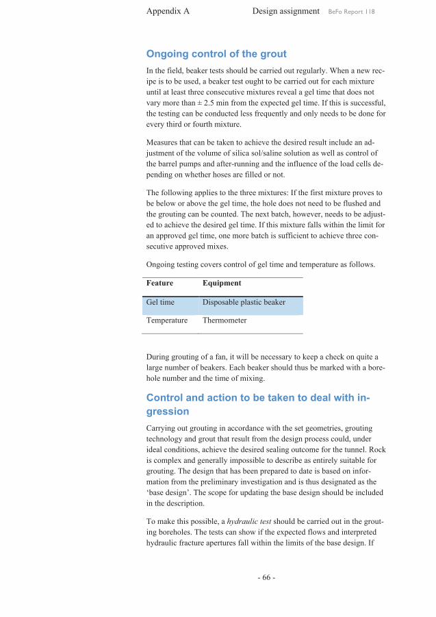
Appendix A Design assignment BeFo Report 118
- 66 -
Ongoing control of the grout In the field, beaker tests should be carried out regularly. When a new rec-ipe is to be used, a beaker test ought to be carried out for each mixture until at least three consecutive mixtures reveal a gel time that does not vary more than ± 2.5 min from the expected gel time. If this is successful, the testing can be conducted less frequently and only needs to be done for every third or fourth mixture.
Measures that can be taken to achieve the desired result include an ad-justment of the volume of silica sol/saline solution as well as control of the barrel pumps and after-running and the influence of the load cells de-pending on whether hoses are filled or not.
The following applies to the three mixtures: If the first mixture proves to be below or above the gel time, the hole does not need to be flushed and the grouting can be counted. The next batch, however, needs to be adjust-ed to achieve the desired gel time. If this mixture falls within the limit for an approved gel time, one more batch is sufficient to achieve three con-secutive approved mixes.
Ongoing testing covers control of gel time and temperature as follows.
Feature Equipment
Gel time Disposable plastic beaker
Temperature Thermometer
During grouting of a fan, it will be necessary to keep a check on quite a large number of beakers. Each beaker should thus be marked with a bore-hole number and the time of mixing.
Control and action to be taken to deal with in-gression Carrying out grouting in accordance with the set geometries, grouting technology and grout that result from the design process could, under ideal conditions, achieve the desired sealing outcome for the tunnel. Rock is complex and generally impossible to describe as entirely suitable for grouting. The design that has been prepared to date is based on infor-mation from the preliminary investigation and is thus designated as the ‘base design’. The scope for updating the base design should be included in the description.
To make this possible, a hydraulic test should be carried out in the grout-ing boreholes. The tests can show if the expected flows and interpreted hydraulic fracture apertures fall within the limits of the base design. If

Appendix A Design assignment BeFo Report 118
- 67 -
not, other grouts could be used as well as a more suitable fan geometry and grouting technique.
To check that the desired sealing outcome is achieved between the bore-holes (that the overlap and the chosen penetration length are working), control holes can be bored as part of a second round, what is termed ‘split spacing’. For a specific section of the tunnel with similar rock conditions, controls can be carried out to a limited extent. Founded on this, the base design can be updated and then applied to the tunnel section further ahead.
A measurement that has been used quite frequently in a number of pro-jects involving silica sol is comparing the median inflow in boreholes be-fore grouting with the median inflows after the first round of grouting in the control hole. A drop in the median ingression compared with the de-sired reduction in transmissivity (factor 50, 100 etc.) should be an indica-tion that the design that has been set up is achieving the desired results. However, it is ingression into the tunnel measured at weirs that confirms whether the results have been achieved. It could be possible to set up temporary measurement weirs while tunnelling to indicate whether the grouting is adequate or not.
During the actual grouting, several observations could lead to the base design being updated. Control is always carried out with the aim of achieving sufficient penetration length in the design fracture aperture and the following observations are controlling factors:
- If the design pressure is not achieved – increase the gel time and re-duce the pressure.
- If the design time is not achieved – reduce the gel time and increase the pressure.
In certain cases, control could result in an unacceptably high volume of grout and excessive time taken. The preparation of a flow diagram that is accessible for the grouting personnel is vitally important. An example is shown below.
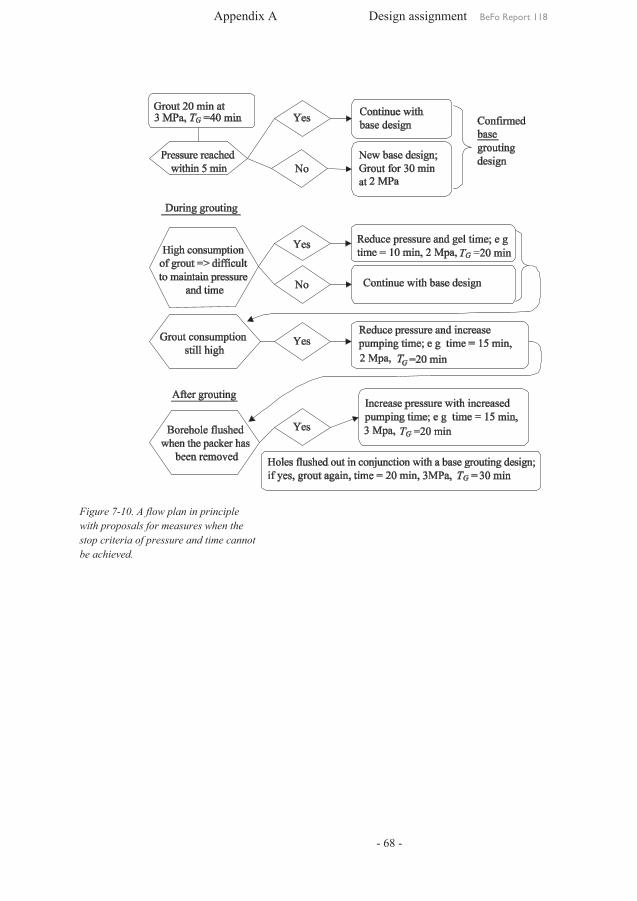
Appendix A Design assignment BeFo Report 118
- 68 -
Figure 7-10. A flow plan in principle
with proposals for measures when the stop criteria of pressure and time cannot be achieved.


BeFo Report 113
MODIFICATION OF ANALYTICAL SOLUTION AND ITS APPLICATION ON PROBABILISTIC DESIGN FOR BLOCK STABILITY
Mehdi Bagheri
Box 5501SE-114 85 Stockholm
[email protected] • www.befoonline.org ISSN 1104-1773Visiting address: Storgatan 19
113