guide to machinery and equipment safety - worksafe qld · pdf filepurchasing machinery and...
TRANSCRIPT

Guide to machinery and equipment safety

PN10596 Version 2 Last updated August 2015 – Guide to machinery and equipment safety 2
Contents
Introduction ................................................................................................................................ 3
Consulting workers and Workplace Health and Safety Representatives ................... 3
1. Key principles of machinery and equipment safety ............................................ 4
1.1 Mechanical hazards ................................................................................................ 4
1.2 Non-mechanical hazards ....................................................................................... 5
1.3 Access hazards ........................................................................................................ 6
Access.......................................................................................................................................... 6
2. Risk control of machinery and equipment hazards ............................................. 9
2.1 Risk control of general hazards ........................................................................... 9
2.2 Risk control of mechanical hazards ................................................................. 10
Guarding .................................................................................................................................... 10
Other mechanical hazard risk control options ................................................................ 13
2.3 Risk control of non-mechanical hazards ......................................................... 15
Personal protective equipment............................................................................................ 16
2.4 Risk control of access hazards .......................................................................... 16
Working at height .................................................................................................................... 17
Lockout tagout: Removing and controlling energy sources during access .......... 18
Identifying energy sources ................................................................................................... 19
De-energise stored energies ................................................................................................ 19
Isolation procedures............................................................................................................... 19
Lockout ...................................................................................................................................... 20
Tagout ........................................................................................................................................ 20
3. Purchasing machinery and equipment list .......................................................... 22
4. Information and guidance ........................................................................................ 24

PN10596 Version 2 Last updated August 2015 – Guide to machinery and equipment safety 3
Introduction A guide to machinery and equipment safety is provided under the Work Health and
Safety Act 2011 (the Act) to assist persons conducting a business or undertaking and
workers comply with their duties under this Act and the Work Health and Safety
Regulation 2011 (the Regulation).
This guide is an introduction to managing the risks associated with use of machinery and
equipment in the workplace.
Relevant persons can use this guide to:
• identify machinery and equipment hazards in the workplace
• eliminate or reduce the risk of those hazards causing harm.
The guide will also be useful to anyone else who is interested in machinery and equipment
safety, such as workers and Workplace Health and Safety Representatives (WHSRs).
Workplace Health and Safety Queensland (WHSQ) also has additional information and
guidance supporting topics introduced in this document. For further information, refer to
Section 4. Consulting workers and workplace health and safety representatives Consultative processes allow people to provide input and raise potential safety concerns
about the work they undertake. Although hazards associated with machinery and equipment
are often easily identified, the ways in which people can gain access to, or may be exposed
to, hazards require a detailed understanding of how they do their job.

PN10596 Version 2 Last updated August 2015 – Guide to machinery and equipment safety 4
1. Key principles of machinery and equipment safety
1.1 Mechanical hazards
Machinery and equipment have moving parts. The action of moving parts may have
sufficient force in motion to cause injury to people.
When assessing machinery and equipment for possible mechanical hazards, consider:
• machinery and equipment with moving parts that can be reached by people
• machinery and equipment that can eject objects (parts, components, products or waste
items) that may strike a person with sufficient force to cause harm
• machinery and equipment with moving parts that can reach people, such as booms or
mechanical appendages (arms)
• mobile machinery and equipment, such as forklifts, pallet jacks, earthmoving equipment,
operated in areas where people may gain access.
Common mechanical hazards and associated risks for machinery and equipment are
shown below.
Hazard Risk
Rotating shafts, pullies, sprockets and gears Entanglement
Hard surfaces moving together Crushing
Scissor or shear action Severing
Sharp edge – moving or stationary Cutting or puncturing
Cable or hose connections Slips, trips and falls (e.g. oil leaks)
Robotic arms can reach over their base, move
with remarkable speed and high force, and can
cause injury if controls to separate people from
moving plant are not implemented.
Mobile plant operated in areas where people work m a y
cause injury through collision. Traffic control and
segregation are forms of control.

PN10596 Version 2 Last updated August 2015 – Guide to machinery and equipment safety 5
1.2 Non-mechanical hazards
Non-mechanical hazards associated with machinery and equipment can include harmful
emissions, contained fluids or gas under pressure, chemicals and chemical by-products,
electricity and noise, all of which can cause serious injury if not adequately controlled. In
some cases, people exposed to these hazards may not show signs of injury or illness for years.
Where people are at risk of injury due to harmful emissions from machinery and equipment,
the emissions should be controlled at their source.
When assessing machinery and equipment for possible non-mechanical hazards, consider
how machinery and equipment can affect the area (environment) around them.
Common non-mechanical hazards are shown below.
Non-mechanical hazards
Dust Mist (vapours or fumes)
Explosive or flammable atmospheres Noise
Heat (radiated or conducted) Ignition sources (flame or spark)
High intensity light (laser, ultraviolet) Molten materials
Heavy metals (lead, cadmium, mercury) Chemicals
Steam Pressurised fluids and gases
Ionising radiation (x-rays, microwaves) Electrical
Woodworking dust generated by a buzzer is
removed via forced extraction and ventilation.
Welding fumes are extracted via flexible,
locatable forced extraction and ventilation
system.

PN10596 Version 2 Last updated August 2015 – Guide to machinery and equipment safety 6
1.3 Access hazards
People must be provided with safe access that is suitable for the work they perform in, on and
around machinery and equipment. A stable work platform, suited to the nature of the work
that allows for good posture relative to the work performed, sure footing, safe environment
and fall prevention (if a fall may occur), is a basic requirement. For example, cooling towers
on building roofs may have poor access, yet must be attended by a service person at
predictable times for water treatment, chemical dosing or monitoring of automated dosing
equipment. People performing these tasks must be provided with the means to get themselves
and any equipment they require onto the roof with no risk, or minimal risk of fall or injury.
When thinking about safe access to machinery and equipment, consider the following:
• who will be working on or around the machinery and equipment
• people who are required to work in enclosed areas where the atmosphere could be
harmful, such as pits, tanks or storage vessels
• what equipment or materials need to be carried to undertake the task
• where and when is access required for operation, maintenance and cleaning
• how will people gain safe access (walkway, gantry, elevated work platform or ladder)
• what work will be carried out during access
• will people be near or exposed to an unidentified mechanical or non-mechanical hazard at
the time of access
• has consultation occurred with workers or contractors regarding how they intend to gain
access, and what equipment and work platform or structure is best suited for the intended task.
Access
Access needs can be predicted and planning must occur in advance. People need access to
machinery and equipment in the workplace (either continually or occasionally) for predictable
tasks such as operation, maintenance, repair, installation, service or cleaning. Access may
vary during each stage of the machinery and equipment life cycle. For example:
• installation or removal
o complete access from every area may be required and involve disconnection or
connection of services, such as water, air, pipes, installation of electrical cable to
switch board
• operation
o access for set up, operation and adjustment
• maintenance, repair, cleaning, alteration or adaptation
o access to remote areas may be required.
Permanently fixed gantries, ladders and walkways
are incorporated into this machinery and
equipment to reduce the risk of a fall from height
occurring during operation and maintenance.
PN10596 Version 2 Last updated August 2015 – Guide to machinery and equipment safety 7
Following are examples of common hazards by type of workplace activity.
People who install or dismantle machinery and equipment could:
• work in isolation
• work on machinery and equipment at height, or over machinery and equipment to connect
services, such as electricity, air or water
• work in low light, or with bright directional light
• access machinery and equipment from the top, sides or underneath
• work with or near cranes, forklifts or rigging to lift machinery and equipment
• work in confined spaces
• use power tools, welders, extension leads, which present electrical hazards if damaged or
wet.
People operating machinery and equipment could:
• be required to place their hands close to the mechanism of the machinery and equipment
that does the work, and may be injured if caught or trapped by moving parts
• be exposed to constant harmful noise, radiated energy or fumes being emitted from the
machinery and equipment being operated, or are close to
• inadvertently bump or knock poorly placed control levers or buttons
• be required to make adjustments to the mechanism of machinery and equipment while the
machine is in motion
• be required to clear away scrap
• make minor adjustments, or reach into the moving mechanism of the machinery and
equipment being operated.
People providing maintenance or repair services could:
• work alone
• work on machinery and equipment at height, or over machinery and equipment to connect
services, such as electricity, air or water
• access machinery and equipment from the rear or sides
• be required to enter confined spaces of larger machinery and equipment
• be trapped by the mechanism of the machinery and equipment through poor isolation of
energy sources or stored energy, such as spring-loaded or counter-balance mechanisms, compressed air or fluids, or parts held in position by hydraulics or pneumatic (air) rams
• move heavy parts when changing the set up of machinery and equipment, or repairing
failed parts, such as electric motors or gear box assemblies
• disable or remove normal safety systems to access the mechanism of machinery and
equipment.

PN10596 Version 2 Last updated August 2015 – Guide to machinery and equipment safety 8
People providing cleaning services could:
• work alone
• access machinery and equipment from the rear or sides, or in unexpected ways
• climb on machinery and equipment
• enter confined spaces, or larger machinery and equipment
• become trapped by the mechanism of the machinery and equipment through poor
isolation of energy sources or stored energy, such as spring-loaded or counter-balance mechanisms, compressed air or fluids, or parts held in position by hydraulics or
pneumatic (air) rams
• work with chemicals
• operate electrical equipment in wet areas.

PN10596 Version 2 Last updated August 2015 – Guide to machinery and equipment safety 9
2. Risk control of machinery and equipment hazards
2.1 Risk control of general hazards
Where exposure to machinery and equipment hazards cannot be eliminated or substituted for
machinery and equipment of improved design, risk controls must be applied to the hazards to
prevent or reduce the risk (chance) of injury or harm. Workplace health and safety laws
require the highest order control be applied.
Higher order machinery and equipment risk controls are preventative by nature, are effective
and durable for the environment it is used in, and deal directly with the hazard at its source.
Lower order machinery and equipment risk controls, such as personal protective equipment
(PPE), can prevent injuries, but are generally not as effective as higher order controls, as they
rely more on worker behaviour, maintenance programs and supervision.
Administrative controls use systems of work to reduce risk by providing a framework of
expected behaviours. Examples are rotation of staff to reduce exposure to a hazard, or a
documented safe system of work, such as ‘lockout tagout’. These types of controls rely on
extensive instruction, information, training and supervision. In terms of time and ongoing
administration by managers and employers to ensure the desired behaviour occurs,
administrative controls can be the most expensive and least effective form of hazard control.
Note: The use of PPE and administrative controls are low or last order controls used to
deal with any residual risk associated with the hazard. As such, these last order controls can
be used in support of higher order controls that deal with a hazard at its source and should
not be considered as the sole means of control. These types of risk controls require constant
monitoring and reinforcement.
Effective machinery and equipment risk controls reflect some or all of the following
characteristics:
• the hazard is controlled at its source
• contact or access to the hazard is prevented
• sturdy construction (correct materials with few points of potential failure)
• fail-safe (failure of the control system to be effective will result in machinery shut-down)
• tamper-proof design (as difficult as possible to bypass)
• presents minimum impediment to machinery and equipment operator
• easy to inspect and maintain
• does not introduce further hazards through the risk control action.
Centre lathe: The exposed rotating chuck of a
centre lathe can eject parts or tools with great force,
cutting fluid fumes are difficult to contain and the
machinery requires manual set-up.

PN10596 Version 2 Last updated August 2015 – Guide to machinery and equipment safety 10
CNC lathe: Substituting a centre lathe with a CNC
lathe (Computer Numeric Control) is an example of
improved risk control of machinery and equipment
through improvement in design.
2.2 Risk control of mechanical hazards
Separation is a simple and effective machinery and equipment risk control and may be
achieved by distance, barrier or time.
• Distance separation means a person cannot reach the hazard due to distance.
• Barrier separation means an effective barrier or guard denies access and controls ejection
of parts, products or waste.
• Time separation means at the time of access, the machinery and/or equipment is disabled.
Examples of separation include:
• physical barriers and guards, such as fences, screens or fixed panels of various materials
• various forms of guarding and interlocking (as described in AS4024, parts 1601 and 1602,
Safety of Machinery)
• making the hazard inaccessible by reach (where the distance between a person and the
hazard forms an effective barrier).
Note: When considering the suitability of distance guarding, consider the safe access
requirements of maintenance people who gain access by ladder, scaffold or elevated work
platform. Guarding
A guard can perform several functions including:
• denying bodily access
• containing ejected parts, tools, off-cuts or swath
• preventing emissions escaping
• forming part of a safe working platform.
Guarding is commonly used with machinery and equipment to prevent access to:
• rotating end drums of belt conveyors
• moving augers of auger conveyors
• rotating shafts
• moving parts that do not require regular adjustment
• machine transmissions, such as pulley and belt drives, chain drives, exposed drive gears
• any dangerous moving parts, machinery and equipment.
Where access is not anticipated, a fixed guard can be permanently applied by a bonding
agent, welding, or secured with one-way screws. If access is generally not required, a
permanently fixed barrier is the preferred option.

PN10596 Version 2 Last updated August 2015 – Guide to machinery and equipment safety 11
Where access to the hazard is infrequent, the installation of a fitted guard, that can be
removed by use of a tool, may be an acceptable control, where the tool to remove the barrier
or guard is not normally available to the operator.
Adjustable guarding incorporates movable sections or panels of the guard and allows for
material or parts to be fed into the guarded area while still preventing bodily contact.
An old style power press incorporating a manual
interlock and adjustable guarding.
If the guard slides up, a connected metal bar
separates the clutch mechanism and the press will
not activate. The guard can be adjusted to provide an
opening by releasing retaining bolts on the guard
face to allow individual panels to move.
Adjustment must be performed by an experienced
person to ensure the resulting opening only provides
room necessary to incorporate the material being fed
in and prevents hands or fingers intruding into the
danger area.
Fences, barriers, guards and interlocked gates separate
people from the hazardous action of machinery and
equipment.
Tunnel guards provide a tunnel, aperture or chute in which material can be inserted into the
machinery and equipment, but due to the restrictive design and depth of the opening, fingers,
hands, arms, or the entire person is prevented from intruding into the danger area.
Where frequent cleaning is required, the guard may be constructed of mesh that prevents
intrusion of body parts, but allows for hosing. Food production workplaces, that use conveyors
in areas where hygiene or food safety is an integral part of the operation, use fixed mesh
guarding of conveyor end rollers.
Interlock guarding occurs when the act of moving the guard (opening, sliding or removing)
to allow access, stops the action of the hazardous mechanism.

PN10596 Version 2 Last updated August 2015 – Guide to machinery and equipment safety 12
Interlock guarding works by:
• disconnecting the drive mechanism mechanically (e.g. applying a brake or disengaging a
clutch or geared mechanism)
• isolating the power source of the drive mechanism (e.g. stopping the motor)
• a combination of mechanical and power disconnection.
Interlock guarding is generally achieved via mechanical or electrical means, but may also
include hydraulic or pneumatic control systems.
The energy stored in moving parts (momentum) can cause the mechanism of the machinery
or equipment to run on for some time after the source of driving energy has been removed.
For access panels or doors supporting an interlocking device allowing access to mechanical
parts that move for periods after the energy source is removed, a separate mechanism to
delay release of the retaining or locking mechanism may be incorporated.
Captive key systems rely upon a single key that is shared between the control panel (‘on’
switch) and the access gate lock of the physical barrier to the danger area. Removal of the
key from the control panel can only occur when the switch is in the ‘off’ position, and the
gate will only release the key when in the locked position.
Captive key systems do not provide full isolation of the power source, but may provide
limited temporary access under controlled conditions.
Administrative controls, such as effective supervision, instruction and training, are required
to ensure that only one key is available for the system, and the key is not removed from the
access gate or guard by a second operator while a person is exposed to the danger area of the
plant. Operations such as maintenance, repair, installation service or cleaning may require all
energy sources to be isolated and locked out to avoid accidental start-up.
The narrow throat of the mincer prevents a
person’s hand from accessing the hazard. Captive key systems: The key cannot be removed
unless it is in the off position. The same key is used to
unlock the access gate. Only one key per system is
retained by the locking mechanism.
PN10596 Version 2 Last updated August 2015 – Guide to machinery and equipment safety 13
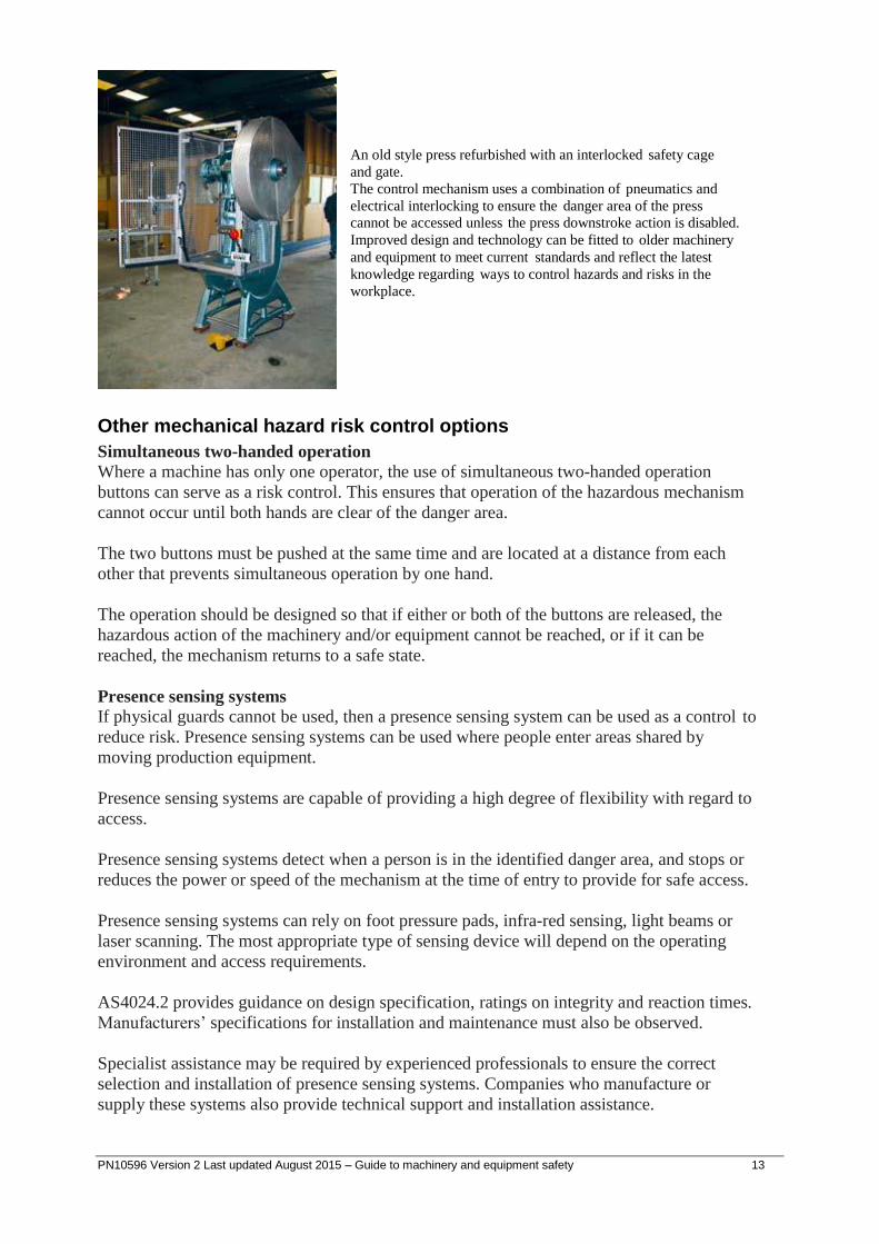
An old style press refurbished with an interlocked safety cage
and gate.
The control mechanism uses a combination of pneumatics and
electrical interlocking to ensure the danger area of the press
cannot be accessed unless the press downstroke action is disabled.
Improved design and technology can be fitted to older machinery
and equipment to meet current standards and reflect the latest
knowledge regarding ways to control hazards and risks in the
workplace.
Other mechanical hazard risk control options
Simultaneous two-handed operation Where a machine has only one operator, the use of simultaneous two-handed operation
buttons can serve as a risk control. This ensures that operation of the hazardous mechanism
cannot occur until both hands are clear of the danger area.
The two buttons must be pushed at the same time and are located at a distance from each
other that prevents simultaneous operation by one hand.
The operation should be designed so that if either or both of the buttons are released, the
hazardous action of the machinery and/or equipment cannot be reached, or if it can be
reached, the mechanism returns to a safe state.
Presence sensing systems If physical guards cannot be used, then a presence sensing system can be used as a control to
reduce risk. Presence sensing systems can be used where people enter areas shared by
moving production equipment.
Presence sensing systems are capable of providing a high degree of flexibility with regard to
access.
Presence sensing systems detect when a person is in the identified danger area, and stops or
reduces the power or speed of the mechanism at the time of entry to provide for safe access.
Presence sensing systems can rely on foot pressure pads, infra-red sensing, light beams or
laser scanning. The most appropriate type of sensing device will depend on the operating
environment and access requirements.
AS4024.2 provides guidance on design specification, ratings on integrity and reaction times.
Manufacturers’ specifications for installation and maintenance must also be observed.
Specialist assistance may be required by experienced professionals to ensure the correct
selection and installation of presence sensing systems. Companies who manufacture or
supply these systems also provide technical support and installation assistance.
PN10596 Version 2 Last updated August 2015 – Guide to machinery and equipment safety 14
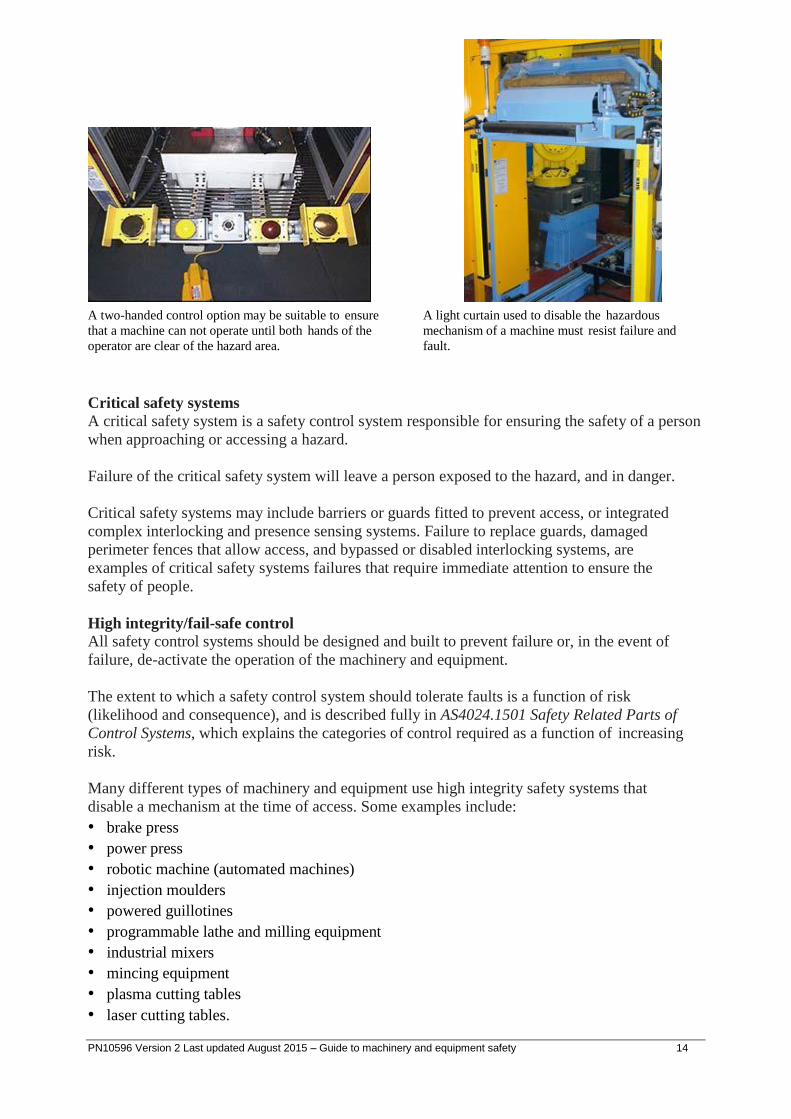
A two-handed control option may be suitable to ensure
that a machine can not operate until both hands of the
operator are clear of the hazard area.
A light curtain used to disable the hazardous
mechanism of a machine must resist failure and
fault.
Critical safety systems
A critical safety system is a safety control system responsible for ensuring the safety of a person
when approaching or accessing a hazard.
Failure of the critical safety system will leave a person exposed to the hazard, and in danger.
Critical safety systems may include barriers or guards fitted to prevent access, or integrated
complex interlocking and presence sensing systems. Failure to replace guards, damaged
perimeter fences that allow access, and bypassed or disabled interlocking systems, are
examples of critical safety systems failures that require immediate attention to ensure the
safety of people.
High integrity/fail-safe control All safety control systems should be designed and built to prevent failure or, in the event of
failure, de-activate the operation of the machinery and equipment.
The extent to which a safety control system should tolerate faults is a function of risk
(likelihood and consequence), and is described fully in AS4024.1501 Safety Related Parts of
Control Systems, which explains the categories of control required as a function of increasing
risk.
Many different types of machinery and equipment use high integrity safety systems that
disable a mechanism at the time of access. Some examples include:
• brake press
• power press
• robotic machine (automated machines)
• injection moulders
• powered guillotines
• programmable lathe and milling equipment
• industrial mixers
• mincing equipment
• plasma cutting tables
• laser cutting tables.
PN10596 Version 2 Last updated August 2015 – Guide to machinery and equipment safety 15
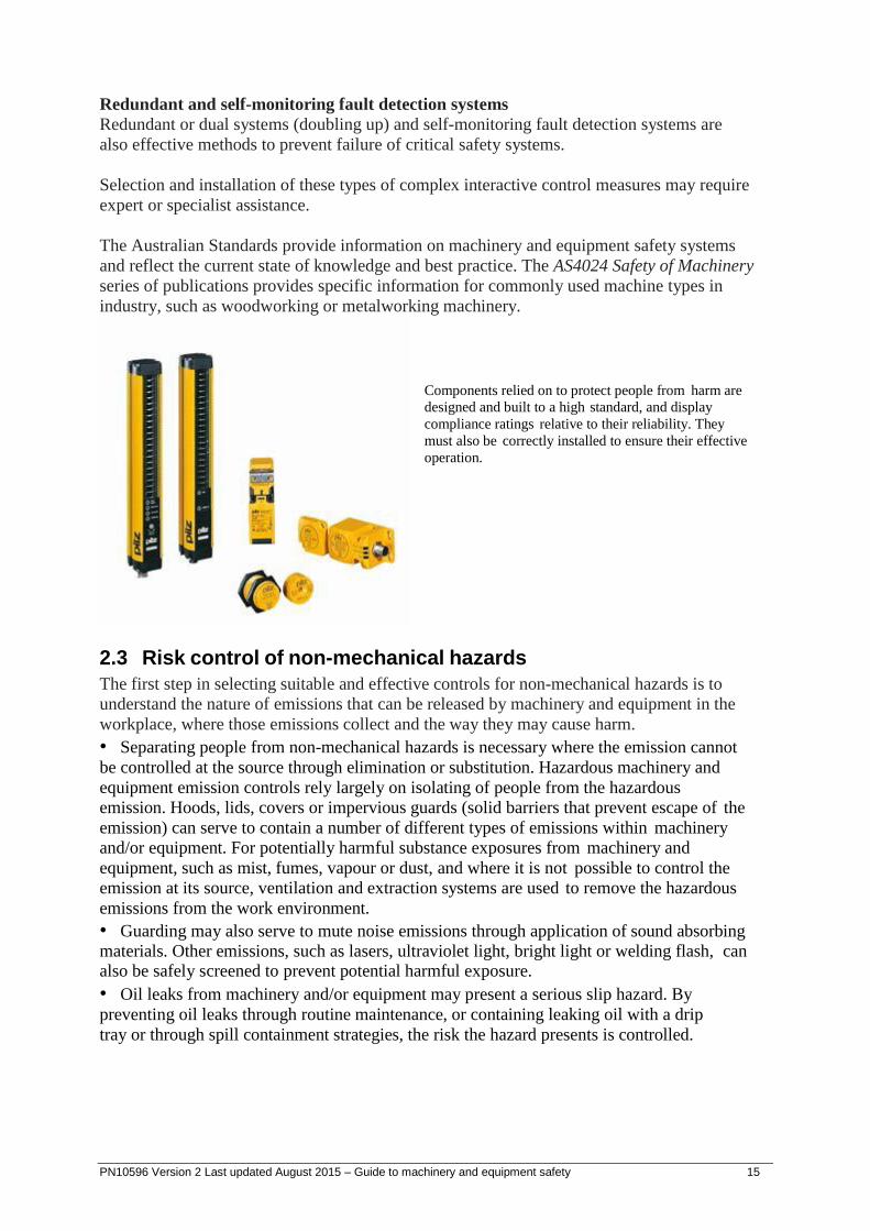
Redundant and self-monitoring fault detection systems
Redundant or dual systems (doubling up) and self-monitoring fault detection systems are
also effective methods to prevent failure of critical safety systems.
Selection and installation of these types of complex interactive control measures may require
expert or specialist assistance.
The Australian Standards provide information on machinery and equipment safety systems
and reflect the current state of knowledge and best practice. The AS4024 Safety of Machinery
series of publications provides specific information for commonly used machine types in
industry, such as woodworking or metalworking machinery.
Components relied on to protect people from harm are
designed and built to a high standard, and display
compliance ratings relative to their reliability. They
must also be correctly installed to ensure their effective
operation.
2.3 Risk control of non-mechanical hazards
The first step in selecting suitable and effective controls for non-mechanical hazards is to
understand the nature of emissions that can be released by machinery and equipment in the
workplace, where those emissions collect and the way they may cause harm.
• Separating people from non-mechanical hazards is necessary where the emission cannot
be controlled at the source through elimination or substitution. Hazardous machinery and
equipment emission controls rely largely on isolating of people from the hazardous
emission. Hoods, lids, covers or impervious guards (solid barriers that prevent escape of the
emission) can serve to contain a number of different types of emissions within machinery
and/or equipment. For potentially harmful substance exposures from machinery and
equipment, such as mist, fumes, vapour or dust, and where it is not possible to control the
emission at its source, ventilation and extraction systems are used to remove the hazardous
emissions from the work environment.
• Guarding may also serve to mute noise emissions through application of sound absorbing
materials. Other emissions, such as lasers, ultraviolet light, bright light or welding flash, can also be safely screened to prevent potential harmful exposure.
• Oil leaks from machinery and/or equipment may present a serious slip hazard. By
preventing oil leaks through routine maintenance, or containing leaking oil with a drip
tray or through spill containment strategies, the risk the hazard presents is controlled.

PN10596 Version 2 Last updated August 2015 – Guide to machinery and equipment safety 16
Personal protective equipment
Where it is not possible for emissions to be controlled at their source, or removed or reduced
through effective ventilation, extraction or diversion, the use of personal protective equipment
(PPE) as a final measure must be considered to ensure safety.
PPE is a lower order control and can only be used where higher order controls are not
possible or are not totally effective.
Selection and use of PPE requires careful consideration, as there are many different types
that reduce the risk of injury of contact or exposure to a hazard.
Incorrect use of PPE, or purchasing inappropriate PPE, can contribute to serious workplace
incidents.
PPE that is uncomfortable, restrictive or heavy may create secondary hazards, and, as a
result, constant supervision may be necessary to ensure it is used effectively.
Ear muffs Gloves Particle half face respirator
Welding mask
Safety glasses
2.4 Risk control of access hazards
Larger machinery and equipment may contain internal areas where a hazardous environment
may occur by design, or as a result of the work being done.
A confined space may exist where people require access to a mostly closed area that presents
difficult or restricted path of access, where oxygen levels may be depleted or displaced, or
where harmful levels of contaminate, such as gas, vapour or dust, exist.
There are legal requirements that must be observed prior to allowing people to enter a
confined space.
• Training in confined space entry.
• Issue of entry permits.
• Continuous monitoring and supervision.

PN10596 Version 2 Last updated August 2015 – Guide to machinery and equipment safety 17
Working at height
Providing people with a suitable work platform for the task being undertaken reduces the risk
of injury from falling from machinery and equipment.
Often ‘safe access’ equipment, made available during installation of machinery and/or
equipment, is removed after commissioning. Workplace managers may not have considered or
recognised the need to provide similar means to gain safe access to parts of machinery and
equipment at height, or in awkward locations for maintenance, repair, service or cleaning
activities.
Safe access at height can be broken into three categories. Each category has in common the
need to provide a stable, safe platform suitable for the work to be undertaken, and to be
equipped to support and retain a person within the confines of the platform.
1. Fixed or permanently installed access platforms:
• gantries
• mezzanine floors
• fixed platforms
• stairways. 2. Mobile elevated work platforms (EWPs):
• scissor lifts
• knuckle booms.
Note: Safe work practices must take into account the risk of trapping an operator between the
EWP and a fixed structure (e.g. overhead beams, electrical cables, pipes).
3. Temporary platforms:
• scaffolding
• ladders.

PN10596 Version 2 Last updated August 2015 – Guide to machinery and equipment safety 18
Where safe working platforms are used and the risk of a fall remains, travel restraint and
fall-arrest harnesses can be used where a suitable point of attachment exists. Harness
systems, anchor points and shock absorbing lanyards must be compatible at each point of
attachment from the anchor point to the harness, with approved and rated latching devices to
ensure the integrity of the system.
When using fall-arrest systems, specialist assistance may be necessary to select appropriate
equipment, provide effective training in use and inspection, and develop an emergency
retrieval plan to recover a person suspended in a fall-arrest harness. People suspended by a
fall-arrest harness for short periods of time may suffer serious health effects, or may have
incurred injury during the fall prior to the fall-arrest device deploying. Emergency retrieval
plans should allow for immediate local response in safely retrieving people to avoid fatalities.
Note: The Work Health and Safety Regulation 2011 prescribes specific requirements that
must be taken into account when determining risk controls for both confined spaces and
working at heights. Lockout tagout: Removing and controlling energy sources during access
People performing tasks, such as maintenance, repair, installation, service and cleaning, are
highly vulnerable, and have a higher risk of being killed or maimed through inadvertent
operation of machinery and equipment they are working in, on or around.
Accidental start-up, or movement of a machine mechanism, can occur:
• if control levers or buttons are bumped or knocked
• if a short circuit of the control system occurs
• when hydraulic or air pressure is released
• when undoing retaining bolts.
It is essential that people who work in, on or around machinery and equipment are not
exposed to hazards due to accidental start-up or movement of the machine mechanism.
(AS4024.1603 Safety of Machinery).
The following is an overview of the lockout tagout process:
• shutdown the machinery and equipment
• identify all energy sources and other hazards
• identify all isolation points
• isolate all energy sources
• de-energise all stored energies
• lockout all isolation points
• tag machinery controls, energy sources and other hazards
• test by ‘trying’ to reactivate the plant without exposing the tester or others to risk (failure
to reactivate ensures that isolation procedures are effective and all stored energies have been dissipated).

PN10596 Version 2 Last updated August 2015 – Guide to machinery and equipment safety 19
Identifying energy sources
All energy sources likely to activate the machinery and equipment and expose people to hazards
should be identified prior to work beginning.
Such energy sources include:
• electricity (mains)
• battery or capacitor banks
• fuels
• heat
• steam
• fluids or gases under pressure (water, air steam or hydraulic oil)
• stored energy
• gravity
• radiation.
If original designer and installer ‘as built’ diagrams of machinery and equipment installations
are not available, new diagrams and photographs showing location and details of various
isolation points of machinery and equipment should be developed as part of the isolation
procedures. Isolation points may include switches, valves, energy lines, pipes and power
sources.
These diagrams and photographs can then be used, along with written procedures, for
information and training. De-energise stored energies
Any or all of the following steps need to be taken to guard against energy left in the
machinery and equipment after it has been isolated from its energy sources:
• inspect the machinery and equipment to make sure all parts have stopped moving
• install ground wires
• release the tension on springs or block the movement of spring-loaded parts
• block or brace parts that could fall
• block parts in hydraulic and pneumatic systems that could move from pressure loss
• bleed the lines and leave vent valves open
• drain process piping systems and close valves to prevent the flow of hazardous material
• if a line must be blocked where there is no valve, use a blank flange
• purge reactor tanks and process lines
• dissipate extreme cold or heat, or provide protective clothing
• if stored energy can accumulate, it must be monitored to ensure it stays below hazardous
levels.
Isolation procedures
Isolation procedures in each workplace vary in detail because of differences in machinery and
equipment, power sources, hazards and processes. However, if adequate interlocking is not
possible, or the maintenance, repair, installation, service or cleaning requires the method of
guarding or interlocking to be bypassed or removed, an isolation procedure should be
implemented.

PN10596 Version 2 Last updated August 2015 – Guide to machinery and equipment safety 20
Note: Activating operational stop buttons, emergency stop devices or interlock devices is not
equivalent to the isolation of power sources, or the release of stored energy.
Lockout
Isolation devices A wide range of devices is available for locking out energy sources and other hazards that could
pose a risk to people working on machinery and equipment.
These devices include switches with a built-in lock, and lockouts for circuit breakers, fuses
and all types of valves.
Also readily available are chains, safety lockout jaws (sometimes called hasps), which
accommodate a number of padlocks, and sets of robust safety padlocks.
Only devices that incorporate a lock or accommodate one or more padlocks are suitable
lockout devices.
One person – one lock If more than one person is working on the same item of machinery and equipment, each
person should attach their own lock to prevent the isolator being opened while their specific
task is in progress.
The isolation procedure should identify common lockout points to ensure energy cannot be
restored while someone is still working on the machinery and equipment.
If two or more people are working on machinery and equipment that is isolated through
several lockout points, each person should attach a lock and tag to each lockout point.
To avoid the need for multiple locks on each lockout point, a lock box may be used. Under
this system, each lockout point is locked by only one lock, and the keys to the locks of the
machinery’s lockout points are placed inside a box that is locked by all the individual locks
of people working on the same plant.
One lock – one key
Each person working on the machinery and equipment should have their own lock, key and
tag. There should be no duplicate key available for any lock, except a master or duplicate
key, for use in an emergency, that is secured and not readily available.
During inspection, repair, maintenance, cleaning or adjustment of the machinery and
equipment, the one key to each person’s lock should be held only by that person, who is
responsible for both locking and unlocking the lockout device.
Multiple energy sources If more than one energy source or hazard has to be locked out to enable safe shut-down of
the machinery and equipment, the single key to each lockout device should be held by the
same person. Tagout
A tag on its own is not an effective isolation device. A tag acts only as a means of providing
information to others at the workplace. A lock should be used as an isolation device, and can
be accompanied by a tag.

PN10596 Version 2 Last updated August 2015 – Guide to machinery and equipment safety 21
Tag and lock Valve lock and tag
Multiple locks

PN10596 Version 2 Last updated August 2015 – Guide to machinery and equipment safety 22
3. Purchasing machinery and equipment list The following list provides topics for consideration and consultation when purchasing
machinery and equipment. It is important to also note that under Sections 22, 23, 24 and 25
of the Work Health and Safety Act 2011, designers, manufacturers, importers and suppliers of
plant have specific duties.
People
• Who will come into contact with the machinery and equipment?
• What are people required to do?
• How will work be carried out and completed?
• Based on the knowledge of existing machinery and equipment, what improvements
should the purchaser specify when buying new machinery and equipment?
Documentation and training
• What supporting documentation will accompany the new machinery and equipment?
• To what standards has the machinery and equipment been manufactured (Australian,
European, Japanese, American)?
• What support is offered by machinery and equipment suppliers (service, training,
maintenance)?
• What operating and maintenance information is supplied with the new machinery and
equipment?
• Is the supplied information sufficient to provide the basis of a workplace training
package?
• If the machinery and equipment is refurbished or second-hand, how do the risk controls
compare with similar new machinery and equipment?
• Have you allowed extra resources to upgrade existing risk controls to reflect current state
of knowledge?
Location
• Where is the machinery and equipment to be located, and how much space does it
require?
• Is there enough room to access the machinery and equipment for servicing, maintenance,
repair or cleaning?
• Do people walk past or work in close proximity to the proposed machinery and
equipment location?
• Is there enough light?
• Is there sufficient ventilation?

PN10596 Version 2 Last updated August 2015 – Guide to machinery and equipment safety 23
Operations and maintenance
• Will the machinery and equipment introduce more noise to the workplace?
• Will the machinery and equipment perform a task other than what it was designed for?
• What types of emissions does the machinery and equipment produce when operated or
cleaned, such as noise, fumes, light and heat?
• What are the expected hours of machinery and equipment operation?
• How will the material arrive, and how is the product going to be removed after the
process is complete?
• Are there environmental factors, such as hazardous atmospheres of flammable vapours or dust or water, that may affect the machinery and equipment, the operators or maintenance?
• Does the machinery and equipment have confined spaces?
• Does the machinery and equipment have valves or isolation points located at height?
Various
• Will the machinery and equipment fit through the door?
• Is the floor of the workplace strong enough to support the machinery and equipment?
• Do you understand that if you purchase machinery and equipment outside Queensland,
then you also take on the obligations of the importer?
• Do you understand the obligations of an importer?
• Do you understand that if you alter or adapt machinery and equipment to perform an
alternate function, then you also take on the obligations of the designer for those alterations?
• Do you understand the obligations of a designer?
• If the machinery and equipment is mobile, where will it operate and who may be in the
area?
• In what terrain will the mobile machinery and equipment operate?

4. Information and guidance Further information about machinery and equipment can be obtained by accessing the Office
of Fair and Safework Queensland website at www.worksafe.qld.gov.au or by calling the
Workplace Health and Safety Queensland Infoline on 1300 362 128.
Legislation:
• Work Health and Safety Act 2011
• Work Health and Safety Regulation 2011
• Electrical Safety Act 2002
• Electrical Safety Regulation 2013
Australian Standards:
Australian Standards are the accepted standards for safeguarding machinery, plant and other issues.
They are developed, published and distributed by Standards Australia. Contact details for Standards
Australia are:
Standards Australia Limited
286 Sussex Street, Sydney, NSW, 2000
GPO Box 5420, Sydney, NSW, 2001
Telephone: +61 2 8206 6000
Email: [email protected]
Website: www.standards.org.au
Other useful publications:
• Managing the risks of plant in the workplace Code of Practice 2013
• How to manage work health and safety risks Code of Practice 2011
• Mobile Crane Code of Practice 2006
• Tower Crane Code of Practice 2006
• Managing risks of hazardous chemicals in the workplace Code of Practice 2013
• Managing noise and preventing hearing loss at work Code of Practice 2011
• Rural Plant Industry Code of Practice 2004
• Relevant manufacturer’s instructions and operator’s instructions/manuals
Workplace Health and Safety Queensland www.worksafe.qld.gov.au 1300 362 128
The material presented in this publication is distributed by the Queensland Government for information only and is subject to change without notice. The Queensland Government disclaims all responsibility and liability (including liability in negligence) for all expenses, losses, damages and costs incurred as a result of the information being inaccurate or incomplete in any way and for any reason.
© State of Queensland 2015 PN10596 Version 2 Last updated August 2015 – Guide to machinery and equipment safety 24