guide to placing, compacting, finishing &...
TRANSCRIPT

GUIDE TO PLACING, COMPACTING,FINISHING & CURING FRESH CONCRETE

Table of Content
Table of content ........................................................................................................ 1Table of figures ......................................................................................................... 3Foreword ................................................................................................................... 4Chapter 1 .............................................................................................................. 5 Compacting concrete ........................................................................................ 5 What is compaction ............................................................................................ 5 Effect on hardened properties ............................................................................. 5 Method and equipment .................................................................................... 6Chapter 2 ............................................................................................................. 7 Finishing concrete............................................................................................. 7 Initial and Final finishing ................................................................................... 7 Floating .............................................................................................................. 8 Final Finishing ................................................................................................... 8Chapter 3 ................................................................................................................. 14 What is curing? .................................................................................................. 14 Why to cure concrete ? .................................................................................... 14 Predictable strength gain. .................................................................................. 14 Improved durability. ........................................................................................... 15 Better serviceability and appearance.................................................................. 16 How to cure ? .................................................................................................... 16 Water Curing ....................................................................................................... 16 Impermeable-membrane Curing......................................................................... 19 Cracks in concrete surfaces ................................................................................. 20 Stress Cracks ........................................................................................................ 20 Shrinkage Cracks ............................................................................................. 20Chapter 4 ................................................................................................................. 23 Forms of Cracks .................................................................................................. 23 Why do concrete surface cracks? ......................................................................... 25 How to prevent or minimize cracking? ................................................................ 25 a- Subgrade and Formwork. ............................................................................. 26 b.- Concrete. .................................................................................................... 26 c-. Finishing. .................................................................................................... 26 d- Curing. ........................................................................................................ 27 e- Joints. .................................................................................................................. 27 f- Cover Over Reinforcement ................................................................................. 27 Reference List ......................................................................................................... 28
Table of Content
Table of Figures
Chapter 1
Chapter 2
Chapter 3
Chapter 4
2 3 4 5 5 5 6 6
12 12 12 12131414141415161616192020202323252526262627272728

Table of figures
Figure 1 The process of compaction .......................................................................... 7Figure 2 Loss of strength through incomplete compaction ......................................... 8Figure 3 Use of an immersion vibrator..................................................................... 11Figure 4 Square pattern for use of immersion vibrator ............................................ 11Figure 5 Compaction at stop ends and inclined forms. ............................................. 12Figure 6 Compaction around void formers and encased members. ........................... 13
Figure 9 Concrete strength with moisture. ............................................................... 15Figure 10 Variation of coefficient of permeability with curing ................................ 16Figure 11 Ponding with water .................................................................................. 17Figure 12 Burlap covering ....................................................................................... 19Figure 13 Different types of compound curing......................................................... 20Figure 14 Plastic shrinkage cracks ........................................................................... 22Figure 15 Cracks due to improper jointing ............................................................... 23Figure 16 Cracks due to continuous external restraint .............................................. 24Figure 17 Cracks due to lack of isolation joints ....................................................... 24Figure 18 Cracks from freezing and thawing .......................................................... 24Figure 19 Craze Cracks ........................................................................................... 25Figure 20 Settlement cracks ..................................................................................... 25
Figure 7 Method of Floating ...................................................................................... 5Figure 8 Methos of Trowelling .................................................................................. 6
5699
10111213151617192022232424242525
Table of Content
Table of Figures
Chapter 1
Chapter 2
Chapter 3
Chapter 4

QA/QC Department
4
Foreword
This guide discusses the benefits of compaction and finishing of concrete andprovides information on the techniques for undertaking the process on site.Also it provides information about cracks and on the importance of curing and thetechniques for undertaking the process on site
Curing has long been recognized as an important process in constructing durableconcrete. After compaction and finishing concrete, proper curing allows the concreteto develop its potential strength and durability. Inadequate curing can result in surfacedamage in the form of plastic shrinkage cracking, spalling, and erosion of paste. Sincemany variables influence the choice of curing materials, when, and how to applycuring, the guidance contained in this document should be very helpful to thoseresponsible for concrete curing operations.
It was developed through a review of many references and especially the ACIstandards, ASTM standards and the PCA (Portland cement association).
This guide includes answers on three important questions:
-What is finishing concrete ? When and how ?-What is compacting concrete ? When and how ?-What is curing concrete ? When and how?
.
Table of Content
Table of Figures
Chapter 1
Chapter 2
Chapter 3
Chapter 4

QA/QC Department
5
Chapter 1Compacting concrete
First the aggregate particles are set in motion and slump to fill the form giving a level top surface. In the second stage, entrapped air is expelled. It is important to recognise the two stages in the compaction process because, with vibration, initial consolidation of the concrete can often be achieved relatively quickly. The concrete liquefiesand the surface levels, giving the impression that the concrete is compacted. Entrapped air takes a little longer to rise to the surface. Compaction must therefore be prolonged until this is accomplished, until air bubbles no longer appear on the surface.
What is compactionCompaction is the process which expels entrapped air from freshly placed concrete and packs the aggregate particles together so as to increase the density of concrete. It increases significantly the ultimate strength of concrete and enhances the bond with reinforcement. It also increases the abrasion resistance and general durability of the concrete, decreases the permeability and helps to minimise its shrinkage-and-creepcharacteristics. Proper compaction also ensures that the formwork is completely filled ( there are no pockets of honeycombed material ) and that the required finish is obtained on vertical surfaces. When first placed in the form, normal concretes, excluding those with very low or very high slumps, will contain between 5% and 20% by volume of entrapped air. The aggregate particles, although coated with mortar, tend to arch against one another and are prevented from slumping or consolidating by internal friction. Compaction of concrete is, therefore, a two-stage process.
Figure 1. The process of compaction
STAGE 1 STAGE 2
PROCESS: Liquefaction of theallows in to slump
and fill the form
PROCESS: The expulsion ofentrapped air
TIME: 3 TO 5 Seconds TIME: 7 TO 15 Seconds
TOTAL TIME (for both stages of the process): 10 to 20 seconds
Table of Content
Table of Figures
Chapter 1
Chapter 2
Chapter 3
Chapter 4

QA/QC Department
6
Method and equipment
Effect on hardened properties
As may be seen from Figure 4, the effect of compaction on compressive strength is dramatic. For example, the strength of concrete containing 10% of entrapped air (air voids) may be as little as 50% that of the concrete when fully compacted. Permeability may be similarly affected since compaction, in addition to expelling entrapped air, promotes a more even distribution of pores within the concrete, causing them to become discontinuous. This reduces the permeability of the concrete and hence improves its durability. The abrasion resistance of concrete surfaces is normally improved by adequate compaction. However, excessive vibration, or excessive working of the surface, can cause an excessive amount of mortar (and moisture) to collect at the surface, thereby reducing its potential abrasion resistance. In flatwork therefore, a careful balance is required to expel entrapped air without bringing excessive amounts of mortar to the surface of the concrete.
Figure 2. Loss of strength through incomplete compaction
GeneralTwo types of vibrators are common on building sites – immersion vibrators andsurface vibrators. Each has its own specific application, although on floors and other
Table of Content
Table of Figures
Chapter 1
Chapter 2
Chapter 3
Chapter 4

QA/QC Department
7
flatwork it is not uncommon for one to complement the other. A third type, formvibrators are commonly used in precast work, and sometimes on building sites.
Immersion Vibrators
Frequently referred to as ‘poker’ or ‘needle ’ vibrators, immersion vibrators consist essentially of a tubular housing which contains a rotating eccentric weight. The out of- balance rotating weight causes the casing to vibrate and, when immersed in concrete, the concrete itself. Depending on the diameter of the casing or head, and on the frequency and the amplitude of the vibration, an immersion vibratormay have a radius of action between 100 and 600 mm.
Immersion vibrators may be driven by:
?A flexible shaft connected to a petrol, diesel, or electric motor. ?An electric motor situated within the tubular casing.?Compressed air.
The effectiveness of an immersion vibrator is dependent on its frequency and amplitude, the latter being dependent on the size of the head, the eccentric moment and the head weight – the larger the head, the larger the amplitude.
Table of Content
Table of Figures
Chapter 1
Chapter 2
Chapter 3
Chapter 4
QA/QC Department
8
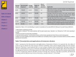
Table 1 Characteristics and applications of immersion vibrators
Table 1 summarises the characteristics and applications of immersion vibrators. As a general rule, the radius of action of a given vibrator not only increases with the workability of the concrete (higher slump), but also with the diameter of the head. A good general rule is to use as large a diameter head as practicable, bearing in mind that vibrators with diameters in excess of 100 mm will probably require two men to handle them. Below this diameter, the appropriate head size will be dependent on the width of the formwork, the spacing of the reinforcement and the cover to it. Immersion vibrators should be inserted vertically into concrete, as quickly as possible, and then held stationary until air bubbles cease to rise to the surface, usually in about 15–20 seconds
Diameter of head
Recommended frequency1
Average amplitude
Radius of action
Rate of concrete placement Application
20-40
30-65
50-90
75-150
125-175
150-250
140-210
130-200
120-180
90-140
0.4-0.8
0.5-1.0
0.6-1.3
0.8-1.5
1.0-2.0
75-150
125-250
175-350
300-500
400-600
1-4
2-8
6-20
11-31
19-38
High slump concrete in very thin members and confined places. May be used to supplement larger vibrators where reinforcement or ducts cause congestion in forms.
Concrete of 100-150 mm slump in thin walls, column, beams, precast piles, thin slabs, and along construction joints. Maybe used to supplement larger vibrators in confined areas.
Concrete (less than 80 mm slump) in normal construction, eg walls, floors, beams and columns in building .
Mass and structural concrete of 0 to 50 mm slump deposited in 3
quantities up to 3m in relatively ope forms of heavy construction.
Mass concrete in gravity dams, large piers, massive walls, etc.
Adapted from Table 5.1 ACI Committee Report: Guide for Consolidation of Concrete 309R-05 ACI Manual of Concrete Practice 2006 Part 2.
1. While vibrator is operating in concrete.2. Computed or measured. This is peak amplitude (half the peak-to-peak value), Operation in air. Reduced by 15-20% when operating in concrete.3. Distance over which concrete is fully consolidated.
14. Assumes insertion spacing 1 / time the radius of action, and that vibrator operates two-thirds of time concrete is being placed.2
5. Reflect not only the capability of the vibrator but also differences in workability of the mix, degree of de-aeration desired, and other conditions experienced in construction.
Table of Content
Table of Figures
Chapter 1
Chapter 2
Chapter 3
Chapter 4

QA/QC Department
9
Figure 3. Use of an immersion vibrator
The vibrator should then be slowly withdrawn and reinserted vertically in a fresh position adjacent to the first. These movements should be repeated in a regular pattern until all the concrete has been compacted.
Random insertions are likely to leave areas of the concrete un-compacted. The vibrator should not be used to cause concrete to flow horizontally in the forms, as this can lead to segregation. In addition, the vibrator should not be dragged through the concrete as this leads to inadequate compaction and increases the risk of segregation. In deep sections such as walls, footings and large columns, the concrete should be placed in layers about 300 mm thick. The vibrator should penetrate about 150 mm into the previous layer of fresh concrete to meld the two layers together and avoid ‘cold-pour/cold-joints’ lines on the finished surface. In small columns where concreting is continuous, the vibrator may be slowly raised as the concrete is placed.
Figure 4. Square pattern for use of immersion vibrator
Radius of action ImmersionVibration
Table of Content
Table of Figures
Chapter 1
Chapter 2
Chapter 3
Chapter 4

QA/QC Department
10
Place concretea little awayfrom the corner
With immersion vibrationmove concrete into thecorner and up the form face
Care should be taken to avoid trapping air at the form face and a means of lighting the interior of the form while the concrete is being placed and vibrated should be considered. The vibrator should not be allowed to touch the forms as this can cause ‘burn’ marks which will be reflected on the finished surface. Generally, the vibrator should be kept about 50 mm clear of the form face. Similarly, the vibrator should not be held against the reinforcement as this may cause its displacement. Stop-ends, joints and, especially, inclined forms are prone to trapping air. To minimise this tendency, the best technique is to place the concrete close to, but away from the side of the form and insert the immersion vibrator close to the leading edge of the concrete, forcing it to properly fill the corner .
Figure 5. Compaction at stop ends and inclined forms.
Void-formers are also prone to trapping air on their undersides if concrete is placed from both sides and then compacted. Concrete should be placed at one side and, maintaining a head, vibrated until it appears at the other side. (Note that the void former will need to be fixed so as to resist the pressure of the plastic concrete.) When the top of the concrete is fully visible from above, then placing can continue normally
Table of Content
Table of Figures
Chapter 1
Chapter 2
Chapter 3
Chapter 4

QA/QC Department
11
Figure 6. Compaction around void formers and encased members.
This technique is used in other similar situations, such as encasing steel beams.
First layer placed and compacted Second and subsequent placementmade from one side only.
Concrete induced to flow underthe void former by action of immersion vibrator
When concrete reaches the samelevel on each of the former,concrete placement and compaction can proceed normally
Similar techniques to that above,used for encasing steel beams.
Concrete placed and compacted form one side until equalisedeither side of beam
Table of Content
Table of Figures
Chapter 1
Chapter 2
Chapter 3
Chapter 4

QA/QC Department
12
Chapter 2
Finishing concrete
Figure 7 Method of Floating
Finishing is screeding, floating or trowelling the concrete surface to densify andfurther compact the surface of concrete, as well as giving it the look you want. Thisstep is to take into consideration before curing concrete. Finishing takes place in two stages:
Initial and Final finishingInitial finishing Concrete is first screeded to the level of the formwork, then bull floated and left to set. In some cases screeding leaves a good enough finish, especially if floor coverings are to be used over the concrete. Water then appears on the surface of the concrete. This water is called bleed water.No final finishing can begin until the bleed water has dried up. Mixing bleed water with the surface paste will weaken it, possibly resulting in a dusty surface.Never try to dry up the bleed water using stone dust or cement as this will weaken the concrete surface in the long run.Once the bleed water dries up and concrete can support a person's weight, with only a slight marking to the surface, the final finishing can begin.
FloatingThere may be two stages in floating: The BULLFLOAT, which is part of the initial float.The POWER or HAND FLOAT which is part of the final float. Floating helps compact and level the surface and close minor cracks. Floating can be done by hand or with a power float. Power floating leaves a better finish than hand floating.
Table of Content
Table of Figures
Chapter 1
Chapter 2
Chapter 3
Chapter 4

QA/QC Department
13
Final Finishing
This involves floating, trowelling, edging the concrete. Trowelling leaves a dense, hard, smooth and durable surface. The surface should be trowelled twice.A well trowelled surface will be very smooth and ca be slippery when wet.Trowelling can be done by hand or power trowel.Edging and Grooving All the edges of a slab should be finished with a special edging tool. This gives a neater and stronger edge, less prone to chipping.
Figure 8. Methods of Trowelling
Table of Content
Table of Figures
Chapter 1
Chapter 2
Chapter 3
Chapter 4

QA/QC Department
14
Chapter 3
What is curing?Curing is the maintaining of an adequate moisture content and temperature in concrete at early ages so that it can develop properties the mixture was designed to achieve. Curing begins immediately after placement and finishing so that the concrete may develop the desired strength and durability. Without an adequate supply of moisture, the cementitious materials in concrete cannot react to form a quality product. Drying may remove the water needed for this chemical reaction called hydration and the concrete will not achieve its potential properties.Temperature is an important factor in proper curing, since the rate of hydration, and therefore, strength development, is faster at higher temperatures. Generally, concrete temperature should be maintained above 50°F (10°C) for an adequate rate of strength development. Further, a uniform temperature should be maintained through the concrete section while it is gaining strength to avoid thermal cracking. For exposed concrete, relative humidity and wind conditions are also important; they contribute to the rate of moisture loss from the concrete and could result in cracking, poor surface quality and durability. Protective measures to control evaporation of moisture from concrete surfaces before it sets are essential to prevent plastic shrinkage cracking.
Why to cure concrete ?Concrete should be cured for several reasons are:
Predictable strength gainLaboratory tests show that concrete in a dry environment can lose as much as 50 percent of its potential strength compared to similar concrete that is moist cured. Concrete placed under high temperature conditions will gain early strength quickly but later strengths may be reduced. Concrete placed in cold weather will take longer to gain strength, delaying form removal and subsequent construction. According to the Portland cement association, the figure shown below concrete that is in air entire time is only 55% of the strength of “Moist-cured entire time “ concrete at 28 days . In air after 3 days is 80%, and in air after 7 days is 90 %.
Table of Content
Table of Figures
Chapter 1
Chapter 2
Chapter 3
Chapter 4

QA/QC Department
15
Com
pre
ssiv
e st
rength
, M
pa
60
50
40
30
20
10
0
8
6
4
2
0
Com
pre
ssiv
e st
rength
, 1000 p
si
Moist-cured entire time
In air after 28 days moist curing
In air after 7 days moist curing
In laboratory air entire time
Age at test, days
Figure 9. Concrete strength with moisture
According to the ACI 308 standard, the concrete should be cured for 7 days for a type I. The longer the concrete is cured, the closer it will be to its possible strength and durability.
Improved durability
Well-cured concrete, has better surface hardness and will better withstand surface wear and abrasion. Curing also makes concrete more watertight, which prevents moisture and water-borne chemicals from entering into the concrete, thereby increasing durability and service life. Figure 2 illustrates the effect of different periods of water curing on the permeability of cement paste. As may be seen, extending the period of curing reduces the permeability.
Table of Content
Table of Figures
Chapter 1
Chapter 2
Chapter 3
Chapter 4

QA/QC Department
16
Figure 10. Variation of coefficient of permeability with curing Better serviceability and appearance.
A concrete slab that has been allowed to dry out too early will have a soft surface with poor resistance to wear and abrasion. Proper curing reduces crazing, dusting and scaling.
How to cure ?
Methods of curing concrete fall broadly into the following categories:- Those that minimise moisture loss from the concrete, for example by covering it with a relatively impermeable membrane.- Those that prevent moisture loss by continuously wetting the exposed surface of the concrete.- Those that keep the surface moist and, at the same time, raise the temperature of the concrete, thereby increasing the rate of strength gain. This method is typically used for precast concrete products.
Water Curing
General Water curing is carried out by supplying water to the surface of concrete in a way that ensures that it is kept continuously moist. The water used for this purpose should not be more than about 5°C cooler than the concrete surface. Spraying warm concrete with cold water may give rise to ‘thermal shock’ that may cause or contribute to cracking. Alternate wetting and drying of the concrete must also be avoided as this causes volume changes that may also contribute to surface crazing and cracking.
Table of Content
Table of Figures
Chapter 1
Chapter 2
Chapter 3
Chapter 4

QA/QC Department
17
Sprinkling or fog curing
Sprinkling or fog curing Using a fine spray or fog of water can be an efficient method of supplying additional moisture for curing and, during hot weather, helps to reduce the temperature of the concrete.
PondingPonding flat or near-flat surfaces such as floors, pavements, flat roofs and the like may be cured by ponding. A ‘dam’ or ‘dike’ is erected around the edge of the slab and water is then added to create a shallow ‘pond’ as shown in Figure 6. Care must be taken to ensure the pond does not empty due to evaporation or leaks.Ponding is a quick, inexpensive and effective form of curing when there is a ready supply of good ‘dam’ material (eg clay soil), a supply of water, and the ‘pond’ does not interfere with subsequent building operations. It has the added advantage of helping to maintain a uniform temperature on the surface of the slab. There is thus less likelihood of early age thermal cracking in slabs that are cured by water ponding.
evaporation from water surface
Schematic diagram of ideal curing of concrete by supplying water
water supplied from externalsource
concretesaturated
Figure 11. Ponding with water
Table of Content
Table of Figures
Chapter 1
Chapter 2
Chapter 3
Chapter 4

QA/QC Department
18
As with other methods of moist curing, it is important that the sprinklers keep the concrete permanently wet. However, the sprinklers do not have to be on permanently; they may be on an intermittent timer. Sprinklers require a major water supply, can be wasteful of water and may need adrainage system to handle run-off. The alternative is to have a ‘closed’ system where the water is collected and recycled. Sprinkler systems may be affected by windy conditions and supervision is required to see that all of the concrete is being kept moist and that no part of it is being subjected to alternated wetting and drying. This is not easy to achieve.
Wet coverings Fabrics
Wet coverings Fabrics such as burlap, or materials such as sand, can be used like a ‘mulch’ to maintain water on the surface of the concrete. On flat areas, fabrics may need to be weighed down. Also, it is important to see that the whole area is covered. Wet coverings should be placed as soon as the concrete has hardened sufficiently to prevent surface damage. They should not be allowed to dry out as they can act as a wick and effectively draw water out of the concrete. Fabrics may be particularly useful on vertical surfaces since they help distribute water evenly over the surface and even where not in contact with it, will reduce the rate of surface evaporation. Care should be taken however, that the surface of the concrete is not stained, perhaps by impurities in the water, or by the covering material. New fabrics can leach fabric stains, pre-washing should be essential. Prior to placement of any fabric – pre moisten to avoid wicking of moisture from the concrete that can result in the fabric texture negatively absorbed into the concrete surface.
Table of Content
Table of Figures
Chapter 1
Chapter 2
Chapter 3
Chapter 4

QA/QC Department
19
Figure 12. Burlap covering
Impermeable-membrane Curing
FormworkLeaving formwork in place is often an efficient and cost-effective method of curing concrete, particularly during its early stages
Plastic sheetingPlastic sheets, or other similar material, form an effective barrier against water loss, provided they are kept securely in place and are protected from damage. Their effectiveness is very much reduced if they are not kept securely in place. The movement of forced draughts under the sheeting must be prevented. They should be placed over the exposed surfaces of the concrete as soon as it is possible to do so without marring the finish.
Membrane-forming curing compoundsCuring compounds are liquids which are usually sprayed directly onto concrete surfaces and which then dry to form a relatively impermeable membrane that retards the loss of moisture from the concrete.
Table of Content
Table of Figures
Chapter 1
Chapter 2
Chapter 3
Chapter 4

QA/QC Department
20
Internal curing compoundsThese are incorporated into the concrete as an admixture hence known as internal curing compounds. They inhibit moisture loss and thereby improve long term strength and reduce drying shrinkage. Internal curing compounds are relatively new and care should be taken when utilised. They have been used in tunnel linings and underground mines to provide at least partial curing when traditional methods are difficult or even impossible to employ.
Cracks in concrete surfacesTwo basic causes of cracks in concrete are stress due to applied loads and stress due to drying shrinkage or temperature changes.
Stress CracksStress cracks can be eliminated by having a proper sub-base and proper concrete design for the load.
Shrinkage CracksDrying shrinkage is an inherent, unavoidable property of concrete. To minimize these cracks we need proper placement of saw cuts, and proper curing to hold the moisture in the concrete long enough to get adequate tensile strength gain in the concrete before the moisture leaves and the concrete shrinks. With adequate strength the concrete should pull together and crack in the saw cuts and not in between them.
Their properties and use are described in AS 3799 Liquid Membrane-forming Curing Compounds for Concrete.
Figure 13 Different types of compound curing
Table of Content
Table of Figures
Chapter 1
Chapter 2
Chapter 3
Chapter 4

QA/QC Department
21
Plastic Shrinkage CracksPlastic Shrinkage Cracks is a type of cracking that appears on the surface of freshly placed concrete during finishing operations, or soon after. Most often, this form of cracking is caused by the rate of evaporation water being greater than the rate at which it is being replaced by bleed water. The surface shrinks while underlying concrete maintains a constant volume.
Contributing factors:a. increased wind velocity.b. ambient temperature increasec. a decrease in relative humidity.
To minimize plastic cracking:a. dampen the subgrade.b. don't work in the sun or wind, erect a roof over the slab and a wind barrier.c. schedule work for the early morning or late afternoon.d. have sufficient man power and equipment.e. cover the concrete with poly in between finishing operations.f. spray on a evaporation retarder, Tri-Film, to form a liquid monomolecular barrieron the surface of the concrete after each finishing operation.
Table of Content
Table of Figures
Chapter 1
Chapter 2
Chapter 3
Chapter 4

QA/QC Department
22
Figure 14. Plastic shrinkage cracks
Craze CrackingCrazing is the occurrence of numerous fine hair cracks in the surface of a newly hardened slab due to surface shrinkage. These cracks form an overall hexagonal pattern.
Causes: a. Rapid surface drying usually caused by either high air temperatures, hot sun, or drying winds, or a combination of these.b. not using an evaporation retarder during placement in hot or windy conditions.c. excessively high slump, over troweling the surface, floating the surface when there is an excess amount of moisture at the surface.d. over use of a jitterbug, vibrating screed, darby or bull float may contribute by working an excess of mortar to the surface.
Table of Content
Table of Figures
Chapter 1
Chapter 2
Chapter 3
Chapter 4

QA/QC Department
23
Chapter 4
Forms of CracksConcrete, like other construction materials, contracts and expands with changes in moisture and temperature, and deflects depending on load and support conditions. Cracks can occur when provisions to accommodate these movements are not made in design and construction. Some forms of common cracks are:1- Plastic shrinkage cracks 2- Cracks due to improper jointing
Figure 15. Cracks due to improper jointing
3- Cracks due to continuous external restraint
(Example: Cast-in-p1ace wall restrained along bottom edge offooting)Figure 16. Cracks due to continuous external restraint
Table of Content
Table of Figures
Chapter 1
Chapter 2
Chapter 3
Chapter 4

QA/QC Department
24
4- Cracks due to lack of isolation joints
Figure 17. Cracks due to lack of isolation joints
Figure 18. Cracks from freezing and thawing
5- Cracks from freezing and thawing
6- Craze cracks
Figure 19. Craze Cracks
Table of Content
Table of Figures
Chapter 1
Chapter 2
Chapter 3
Chapter 4

QA/QC Department
25
7- Settlement cracks
Figure 20 Settlement cracks
Most random cracks that appear at an early age, although unsightly, rarely affect the structural integrity or the service life of concrete. Closely spaced pattern cracks or Dcracks due to freezing and thawing, that typically appear at later ages, are an exception and may lead to ultimate deterioration.
Why do concrete surface cracks? The majority of concrete cracks usually occur due to improper design and construction practices, such as:Omission of isolation and contraction joints and improper jointing practices.Improper subgrade preparation.The use of high slump concrete or excessive addition of water on the job.Improper fmishing.Inadequate or no curing.
Table of Content
Table of Figures
Chapter 1
Chapter 2
Chapter 3
Chapter 4
QA/QC Department
26
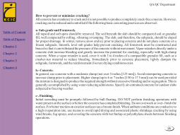
How to prevent or minimize cracking?All concrete has a tendency to crack and it is not possible to produce completely crack-free concrete. However, cracking can be reduced and controlled if the following basic concreting practices are observed:
a- Sub-grade and Formwork.All topsoil and soft spots should be removed. The soil beneath the slab should be compacted soil or granular fill, well compacted by rolling, vibrating or tamping. The slab, and therefore, the subgrade, should be sloped for proper drainage. In winter, remove snow and ice prior to placing concrete and do not place concrete on a frozen subgrade. Smooth, level sub grades help prevent cracking. All formwork must be constructed and braced so that it can withstand the pressure of the concrete without movement. Vapor retarders directly under a concrete slab increase bleeding and greatly increase the potential for cracking, especially with high-slump concrete. When a vapor retarder is used, cover it with 3 to 4 inches of a compactible granular fill, such as a crusher-run material to reduce bleeding. Immediately prior to concrete placement, lightly dampen the subgrade, formwork, and the reinforcement if severe drying conditions exist.
b.- Concrete. In general, use concrete with a moderate slump (not over 5 inches [125 mm]). Avoid retempering concrete to increase slump prior to placement. Higher slump (up to 6 or 7 inches [150 to 17 5 mm]) can be used provided the mixture is designed to produce the required strength without excessive bleeding and/or segregation. This is generally accomplished by using water-reducing admixtures. Specify air-entrained concrete for outdoor slabs subjected to freezing weather.
c-. Finishing.Initial screeding must be promptly followed by bull floating. DO NOT perform fmishing operations with water present on the surface or before the concrete has completed bleeding. Do not overwork or over- finish the surface. For better traction on exterior surfaces use a broom fmish. When ambient conditions are conducive to a high evaporation rate, use means to avoid rapid drying and associated plastic shrinkage cracking by using wind breaks, fog sprays, and covering the concrete with wet burlap or polyethylene sheets between finishing operations.
Table of Content
Table of Figures
Chapter 1
Chapter 2
Chapter 3
Chapter 4

QA/QC Department
27
d- Curing.Curing is an important step to ensure durable crack-resistant concrete. Start curing as soon as possible. Spray the surface with liquid membrane curing compound or cover it with damp burlap and keep it moist for at least 3 days. A second application of curing compound the next day is a good quality assurance step.
e- Joints.Anticipated volumetric changes due to temperature and/or moisture should be accommodated by the construction of contraction joints by sawing, forming or tooling a groove about 1/4 to 113 the thickness of the slab, with a spacing between 24 to 36 times the thickness. Tooled and saw-cut joints should be run at the proper time. A maximum 15 feet spacing for contraction joints is often recommended. Panels between joints should be square and the length should not exceed about 1.5 times the width. Isolation joints should be provided whenever restriction to freedom of either vertical or horizontal movement is anticipated-such as where floors meet walls, colunms, or footings. These are full-depth joints and are constructed by inserting a barrier of some type to prevent bond between the slab and the other elements.
f- Cover Over Reinforcement.Providing sufficient concrete cover (at least 2 inches [50 mm]) to keep salt and moisture from contacting the steel should prevent cracks in reinforced concrete caused by expansion of rust on reinforcing steel.
Table of Content
Table of Figures
Chapter 1
Chapter 2
Chapter 3
Chapter 4

QA/QC Department
28
Reference List
-Manual of Concrete Inspection, American Concrete Institute.
-Effect of curing condition on compressive strength of concrete test speciemens, NRMCA publication No 53,
National ready mixed concrete association, Silver spring MD
-Standard practice for curing concrete, ACI 308, Aerican concrete institute, Flamington hills,MI
-Standard specification for curing concrete, ACI 308.1, American concrete institute, Flamington hills,MI
-Guide to Concrete Construction C&CAA T41 – 2002
-Concrete Practice on Building Sites C&CAA T43 – 1995
-Sheets from www.concrete.net.au.
-PCA Portland cement association.
-Cement concrete & aggregates Australia.
- Control of cracking in concrete structures, ACI 224 R, American concrete institute, Farmington hills, MI.
-Guide for concrete floor and slab construction, ACI 302.1R, American Concrete Institute, Farmington Hills,
MI.
-Cracks in concrete: Causes, Prevention, Repair, A collection of articles from concrete Construction
Magazine, June 1973.
-Grant T. Halvorson, Troubleshooting concrete cracking During construction, Concrete Construction,
October 1993.
-National ready mixed concrete Association, Technical information.
Table of Content
Table of Figures
Chapter 1
Chapter 2
Chapter 3
Chapter 4