guide to wireless communications, third...
TRANSCRIPT

1
Guide to Wireless Communications, Third Edition
Chapter 7Low-Speed Wireless Local Area
Networks
© Cengage Learning 2014Guide to Wireless Communications, Third Edition 2
Objectives
• Describe how WLANs are used
• List the components and modes of a WLAN
• Describe how an RF WLAN works
• Explain the differences between IR, IEEE 802.11, and IEEE 802.11b WLANs
• Outline the user mobility features offered by IEEE 802.11 networks

2
© Cengage Learning 2014Guide to Wireless Communications, Third Edition 3
WLAN Applications
• Wireless networks are increasing in popularity• Installing cabling is inconvenient and very expensive
– Wireless networks solve this problem
• With a wireless network– Multiple users can share a single Internet connection
• Wireless residential gateway– Device that combines a router, Ethernet switch, and
wireless access point; sometimes a cable or DSL modem as well
• Provides better security than connecting directly to the Internet
© Cengage Learning 2014Guide to Wireless Communications, Third Edition 4
WLAN Components
• Minimal hardware needed for a WLAN– Computer
– ISP
– Wireless network interface card
– Access point (AP)

3
© Cengage Learning 2014Guide to Wireless Communications, Third Edition 5
Wireless Network Interface Card
• Network interface card (NIC)– Allows a computer to be connected to a network
• Wireless NIC– Connects a computer to a network without cables
– Uses an antenna instead of cable port
• Mini PCI– Small card that is functionally equivalent to a standard
PCI expansion card
– Used with notebook computers
© Cengage Learning 2014Guide to Wireless Communications, Third Edition 6
Figure 7-1 A mini PCI wireless NIC

4
© Cengage Learning 2014Guide to Wireless Communications, Third Edition 7
Wireless Network Interface Card
• Smaller devices – Already include a wireless radio chip and antenna
• Intel Centrino chipset– Integrates all of the functions of a wireless NIC
– Mounted directly on the motherboard
• Software– Built-in to operating system in most cases
– Can also be a separate program
© Cengage Learning 2014Guide to Wireless Communications, Third Edition 8
Access Points
• Access point (AP)– Provides wireless LAN devices with a point of access
into a wired network
• AP parts– Radio transceiver
– Antenna
– RJ-45 wired network interface port
• AP functions– Wireless communications base station
– Bridge between the wireless and wired networks

5
© Cengage Learning 2014Guide to Wireless Communications, Third Edition 9
Figure 7-2 The AP as the point of access into a wired network
© Cengage Learning 2014Guide to Wireless Communications, Third Edition 10
Access Points
• The range of an AP is approximately 115 meters
• Dynamic rate selection– AP will automatically select the highest possible data
rate for transmission• Depending on the strength and quality of the signal
• An AP can generally support over 100 users– 20-25 is more practical for a heavily used AP
• Power over Ethernet (PoE)– DC power is delivered to the AP through the unused
wires in a standard UTP Ethernet cable

6
© Cengage Learning 2014Guide to Wireless Communications, Third Edition 11
WLAN Modes
• Ad hoc mode
• Infrastructure mode
© Cengage Learning 2014Guide to Wireless Communications, Third Edition 12
Ad Hoc Mode
• Also known as peer-to-peer mode– Formal name: Independent Basic Service Set (IBSS)
mode
• Wireless clients communicate directly among themselves without using an AP– Quick and easy setup of a wireless network
• Drawback is that wireless clients can only communicate among themselves – no wired network access

7
© Cengage Learning 2014Guide to Wireless Communications, Third Edition 13
Figure 7-3 Ad hoc mode
© Cengage Learning 2014Guide to Wireless Communications, Third Edition 14
Infrastructure Mode
• Also known as the Basic Service Set (BSS)– Consists of wireless clients and an AP
• Extended Service Set (ESS)– Two or more BSS wireless networks installed in same
area using the same Service Set Identifier (SSID)• SSID – alphanumeric string that identifies the network
– Provides users with uninterrupted mobile access to the network
• All wireless clients and APs must be part of the same network– For users to be able to roam freely

8
© Cengage Learning 2014Guide to Wireless Communications, Third Edition 15
Figure 7-4 Extended Service Set (ESS)
© Cengage Learning 2014Guide to Wireless Communications, Third Edition 16
Infrastructure Mode
• When more than one AP exists on the same SSID, wireless devices choose which AP to associate with based on signal strength– Devices changes to that APs frequency channel
• Device monitors to see if a different AP can provide better quality signal– Transition from AP to AP is called a handoff

9
© Cengage Learning 2014Guide to Wireless Communications, Third Edition 17
Infrastructure Mode
• Can be difficult to manage one large network– Performance and security may also be adversely
affected
• Subnets– Network units that contain fewer computers
• In an ESS divided into subnets– A mobile user might not be able to freely roam
between APs– Must reconnect between each subnet to get a new IP
address– Some business-class devices solve this problem
© Cengage Learning 2014Guide to Wireless Communications, Third Edition 18
Wireless LAN Standards and Operation
• Most WLANs are based on these same initial IEEE 802.11 standard:– Original standard defines a local area network that
provides cable-free data access for clients• That are either mobile or in a fixed location
– At a rate of either 1 or 2 Mbps• Using either diffused infrared or RF transmission• When using RF; transmissions use FHSS or DSSS
– Specifies that the features of a WLAN be transparent to the upper layers of the TCP/IP protocol stack
• Or the OSI protocol model

10
© Cengage Learning 2014Guide to Wireless Communications, Third Edition 19
Figure 7-5 WLAN features restricted to the PHY and MAC layers
© Cengage Learning 2014Guide to Wireless Communications, Third Edition 20
IEEE 802.11 Standards
• IR and FHSS– No 802.11 equipment introduced into consumer
market using these technologies
• 2 Mbps original standard– Too slow for most applications
– 802.11b and 802.11a were published in 1999 as a response
• Provide 11 and 54 Mbps respectively
– 802.11g providing 54 Mbps and backward compatible to 802.11b introduced in 2003

11
© Cengage Learning 2014Guide to Wireless Communications, Third Edition 21
IEEE 802.11b Standard
• Added two higher speeds, 5.5 Mbps and 11 Mbps
• Specified RF and direct sequence spread spectrum (DSSS) as the only transmission technologies
• Also known as Wi-Fi
• Physical layer– Divided into two parts
• Physical Medium Dependent (PMD)
• Physical Layer Convergence Procedure (PLCP)
© Cengage Learning 2014Guide to Wireless Communications, Third Edition 22
IEEE 802.11b Standard
• Physical layer convergence procedure standards– Based on direct sequence spread spectrum (DSSS)
– Must reformat the data received from the MAC layer into a frame that the PMD sublayer can transmit
– PLCP frame is made up of three parts: the preamble, the header, and the data
– Frame preamble and header are always transmitted at 1 Mbps
• Allows communication between slower and faster devices

12
© Cengage Learning 2014Guide to Wireless Communications, Third Edition 23
Figure 7-6 802.11b PLCP frame
© Cengage Learning 2014Guide to Wireless Communications, Third Edition 24
IEEE 802.11b Standard
• Physical medium dependent standards– Translate the binary 1s and 0s of the frame into radio
signals that can be used for transmission
– 802.11b standard uses the Industrial, Scientific, and Medical (ISM) band
• Specifies 14 available frequencies, beginning at 2.412 GHz and incrementing by .005 GHz (5 MHz)
– PMD can transmit the data at 11,5.5, 2,or 1 Mbps
– For transmissions at 1 Mbps, two-level differential binary phase shift key (DBPSK) modulation is used

13
© Cengage Learning 2014Guide to Wireless Communications, Third Edition 25
Table 7-1 802.11b ISM channels
© Cengage Learning 2014Guide to Wireless Communications, Third Edition 26
IEEE 802.11b Standard
• Physical medium dependent standards – Transmissions at 2, 5.5, and 11 Mbps use differential
quadrature phase shift keying (QPSK)– To transmit at rates above 2 Mbps, Complementary
Code Keying (CCK) is used• A table containing 64 8-bit code words
• Media access control layer– 802.11b Data Link layer consists of two sublayers
• Logical Link Control (LLC) – no changes compared to 802.3 (Ethernet) networks
• Media Access Control (MAC)

14
© Cengage Learning 2014Guide to Wireless Communications, Third Edition 27
IEEE 802.11b Standard
• Coordinating transmissions in the shared wireless medium– Channel access methods can prevent collisions
– One way is for devices to listen before sending and use acknowledgement to ensure delivery – called distributed coordination function (DCF)
– DCF employs Carrier sense multiple access with collision avoidance (CSMA/CA)
• Based on 802.3 CSMA/CD
© Cengage Learning 2014Guide to Wireless Communications, Third Edition 28
Figure 7-7 Frame collision in a wired network

15
© Cengage Learning 2014Guide to Wireless Communications, Third Edition 29
IEEE 802.11b Standard
• Coordinating transmissions in the shared wireless medium – CSMA/CD is designed to handle collisions
• CSMA/CA attempts to avoid collisions altogether
– With contention-based channel access methods• Most collisions occur after a device completes its
transmission
– CSMA/CA makes all devices wait a random amount of time (backoff interval) after the medium is clear
• The amount of time is measured in time slots
– CSMA/CA also reduces collisions by using an explicit acknowledgment (ACK)
© Cengage Learning 2014Guide to Wireless Communications, Third Edition 30
Figure 7-8 CSMA/CA

16
© Cengage Learning 2014Guide to Wireless Communications, Third Edition 31
IEEE 802.11b Standard
• Coordinating transmissions in the shared wireless medium – Additional mechanisms to reduce collisions
• Request-to-send/Clear-to-send (RTS/CTS) protocol
• Fragmentation
– Polling• Another type of channel access method
• Each computer is asked if it wants to transmit
• Polling effectively eliminates collisions
– Point coordination function (PCF)• AP serves as the polling device
© Cengage Learning 2014Guide to Wireless Communications, Third Edition 32
Figure 7-9 RTS/CTS

17
© Cengage Learning 2014Guide to Wireless Communications, Third Edition 33
IEEE 802.11b Standard
• Polling– Another type of channel access method
– Each computer is asked if it wants to transmit
– Polling effectively eliminates collisions
• Polling is known as point coordination function (PCF)• AP serves as the polling device
• Designed for time-sensitive transmissions (voice/video)
• Not used in commercial-grade 802.11 APs
© Cengage Learning 2014Guide to Wireless Communications, Third Edition 34
Figure 7-10 Polling in PCF

18
© Cengage Learning 2014Guide to Wireless Communications, Third Edition 35
IEEE 802.11b Standard
• MAC layer of 802.11b provides functionality to join a WLAN and stay connected– Process known as association and reassociation– Association begins with the client scanning the
wireless medium– Passive scanning
• Client listening to each available channel for a set period of time
• Client listens for a beacon frame transmitted from all available APs
• Frame includes the AP’s SSID and BSSID
© Cengage Learning 2014Guide to Wireless Communications, Third Edition 36
IEEE 802.11b Standard
• Active scanning– Client sends a probe frame to each channel– Client then waits for the probe response frame– Associate request frame
• Includes the client’s capabilities and supported rates
– Associate response frame• Sent by the AP• Contains a status code and client ID number for that
client• Client is now part of the WLAN

19
© Cengage Learning 2014Guide to Wireless Communications, Third Edition 37
IEEE 802.11b Standard
• Reassociation– Client may drop the connection with one AP and
reestablish the connection with another
– Necessary when mobile clients roam beyond the coverage area of one AP
– Client sends a reassociate request frame to new AP
– AP sends back a reassociate response frame
– New AP sends a disassociate frame to old AP to terminate the client’s association to old AP
© Cengage Learning 2014Guide to Wireless Communications, Third Edition 38
Figure 7-11 Reassociation process

20
© Cengage Learning 2014Guide to Wireless Communications, Third Edition 39
IEEE 802.11b Standard
• Power management– Most clients in a WLAN are portable devices
• To conserve battery power, they can go into sleep mode
– When a client is part of a WLAN, it must remain fully powered
– Power management allows the mobile client to shut down its radio to save energy
• But still not miss out on data transmissions
– The key to power management is synchronization
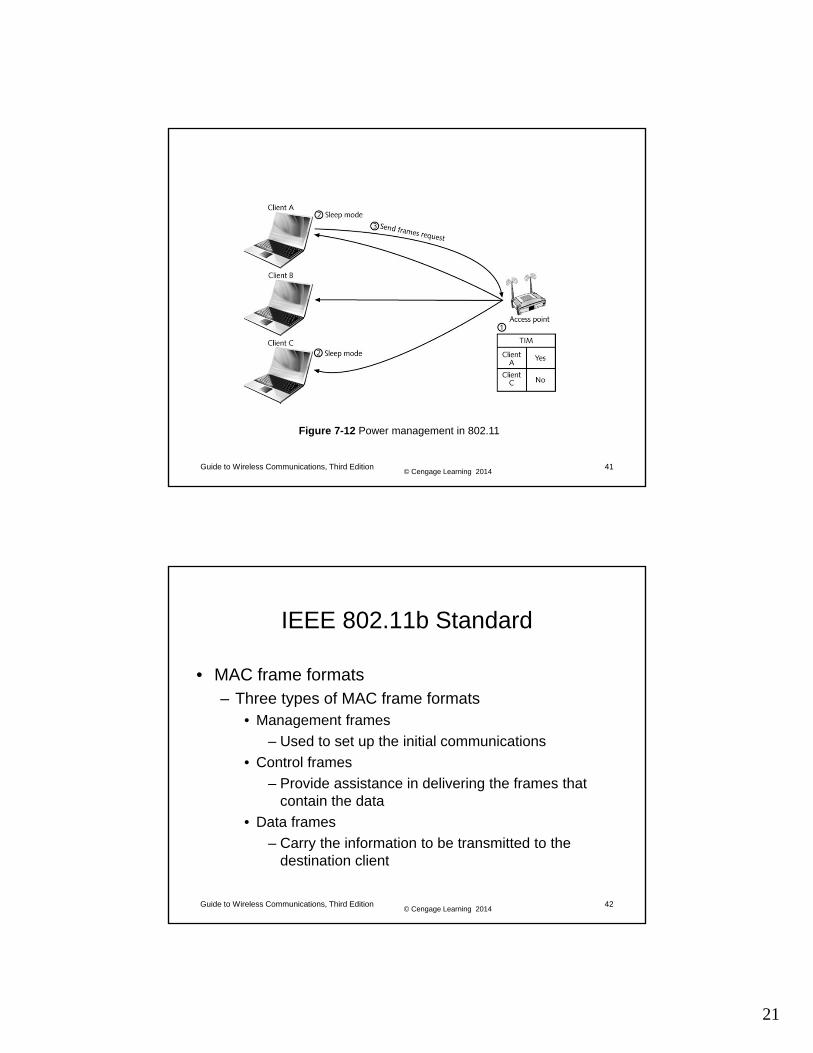
© Cengage Learning 2014Guide to Wireless Communications, Third Edition 40
IEEE 802.11b Standard
• Power management – When a mobile 802.11b client goes into sleep mode,
the AP is informed of the change• AP temporarily stores the frames destined for sleeping
clients (this function is called buffering)
– At predetermined times, the AP sends out a beacon frame to all clients
• Known as the traffic indication map (TIM)
– Traffic indication map (TIM)• List of clients with buffered frames waiting at the AP
21
© Cengage Learning 2014Guide to Wireless Communications, Third Edition 41
Figure 7-12 Power management in 802.11
© Cengage Learning 2014Guide to Wireless Communications, Third Edition 42
IEEE 802.11b Standard
• MAC frame formats– Three types of MAC frame formats
• Management frames
– Used to set up the initial communications
• Control frames
– Provide assistance in delivering the frames that contain the data
• Data frames
– Carry the information to be transmitted to the destination client

22
© Cengage Learning 2014Guide to Wireless Communications, Third Edition 43
Figure 7-13 Structure of a management frame
© Cengage Learning 2014Guide to Wireless Communications, Third Edition 44
Figure 7-13 RTS (control) frame

23
© Cengage Learning 2014Guide to Wireless Communications, Third Edition 45
Figure 7-15 Data frame
© Cengage Learning 2014Guide to Wireless Communications, Third Edition 46
IEEE 802.11b Standard
• 802.11 standard defines a number of interframe spaces (IFS)– To handle the contention for the medium
• Interframe space types– Short interframe space (SIFS)– DCF interframe space (DIFS)
Table 7-2 Interframe space duration

24
© Cengage Learning 2014Guide to Wireless Communications, Third Edition 47
IEEE 802.11b Standard
• Basic rules of communication in an 802.11 network – Device that wants to transmit begins listening for an RF
signal– Size of a frame includes both the length of time necessary
to send the data and the SIFS time– Sending device begins listening for an ACK– After receiving an ACK, the transmitting client begins to wait
a random backoff interval– If the transmitting device does not receive an ACK after the
SIFS• It is allowed to maintain control of the medium
– If the frame was acknowledged correctly• Transmitting device listens to the medium while waiting its
backoff interval
© Cengage Learning 2014Guide to Wireless Communications, Third Edition 48
Figure 7-16 Single device transmitting

25
© Cengage Learning 2014Guide to Wireless Communications, Third Edition 49
IEEE 802.11b Standard
• In the case of two devices having frames to transmit– Client A has a frame to transmit and a backoff counter
of 0; Client B has a backoff period of 2– Client A transmits its first frame
• Client B detects traffic and waits
– After client A transmits, it sets its backoff counter to 3• At the end, clients A and B begin their backoff interval
– Network enters a contention access period• Both clients being counting• After two time slots, client B reaches 0 and transmits
– Once client B receives an ACK, the process continues
© Cengage Learning 2014Guide to Wireless Communications, Third Edition 50
IEEE 802.11b Standard
Figure 7-17 CSMA/CA with two clients transmitting

26
© Cengage Learning 2014Guide to Wireless Communications, Third Edition 51
Summary
• The wireless technology that attracts the most attention today – Radio frequency (RF) wireless local area networks
(WLANs)
• Wireless NIC performs same functions as wired NIC
• Access points parts– Antenna
– Radio transceiver
– RJ-45 wired network interface
© Cengage Learning 2014Guide to Wireless Communications, Third Edition 52
Summary
• Data can be sent and received in an RFWLAN either in ad hoc or infrastructure mode
• IEEE 802.11 standard defines a local area network that provides cable-free data access
• In 1999, IEEE approved 802.11b and 802.11a
• PCLP for 802.11b based exclusively on DSSS
• 802.11 standard uses an access method known as the distributed coordination function (DCF)– Specifies that carrier sense multiple access with
collision avoidance (CSMA/CA) be used

27
© Cengage Learning 2014Guide to Wireless Communications, Third Edition 53
Summary
• 802.11 standard provides for an optional polling function known as point coordination function (PCF)
• Mobile WLAN devices often depend on batteries as their primary power source– Sleep mode conserves battery power
• 802.11 standard specifies three different types of MAC frame formats– Management frames
– Control frames
– Data frames