guided inspection of uml models john d. mcgregor korson-mcgregor (formerly software architects)...
TRANSCRIPT
Guided Inspection of UML ModelsGuided Inspection of UML Models
John D. McGregor
Korson-McGregor(formerly Software Architects)

2
Restricted UseRestricted Use
This copyrighted material is provided to attendees of Korson-McGregor courses under a restricted licensing agreement exclusively for the personal use of the attendees. Korson-McGregor retains ownership rights to the material contained in these course notes.
Please respect these rights.
Copyright © 2000 Korson-McGregor. All rights reserved.Version 2.0

3
OutlineOutline
Basics and Definitions Selecting Test Cases Application of Technique Evaluation of Technique

4
ProblemProblem
Existing inspection and review techniques examine what is in the model for errors.
There is no systematic way to consider what should be in the model.
Guided Inspection is a technique that supplements rigorous inspection and review techniques, that address model syntax, with test cases to systematically examine the semantics of the model.

5
DefinitionsDefinitions
Guided inspection = formal inspection + test cases
Formal inspection included Team of inspectors Guidelines and criteria Standard process
A test case includes Pre-conditions Input scenario Expected results
6
DefinitionsDefinitions
Coverage is a metric that measures what portion of a product has been exercised by the set of tests that have been executed. “100% statement coverage is a basic test adequacy
criteria”
A test case is used because it represents some specific point in the domain (possible inputs) or the range (desired outputs). “Test case 12 represents the scenario in which
Player0 has 3 squares and Player1 has 2 squares..”

7
Testing PerspectiveTesting Perspective
Systematic - We can analyze the material in a specific order.
Objective - Prevents covering only those parts that we understand best.
Variable level of coverage - Algorithms for selecting a specific percentage of the possible test cases.
Variable areas of emphasis - Priorities can be established and enforced for selecting test cases.
8
What’s DifferentWhat’s Different
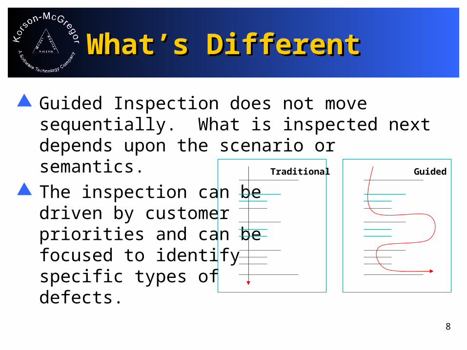
Guided Inspection does not move sequentially. What is inspected next depends upon the scenario or semantics.
The inspection can be driven by customer priorities and can be focused to identify specific types of defects.
Traditional Guided
9
Scenario Driven BenefitsScenario Driven Benefits
The inspection can be driven by customer priorities.
The inspection can be focused to identify defects associated with specific types of inputs.
The inspection can be focused to identify defects associated with specific types of outputs.

10
Components in Guided Inspection Components in Guided Inspection
Checklists The tester completes lists by examining the
products. The lists are standard across
products/projects. Test Cases
The tester creates test cases. The developer supports a symbolic execution. Tests are specific to the product.

11
Guided Inspection StepsGuided Inspection Steps
Analyze the model to be inspected. Complete the checklist for the
appropriate model. Systematically sample to select test
cases. Write down the test cases. Apply the test cases to the model to be
inspected. Analyze the model to determine coverage
levels.

12
Roles in Guided InspectionRoles in Guided Inspection
Tester Select and write test cases.
Developer Perform symbolic execution.
Manager Stay out of the way - this is
defect finding, not a managerial evaluation.

13
Form a TeamForm a Team
We will be performing a Guided Inspection. Choose four or five partners for these
exercises. Agree on roles - no fair being the manager. Half the team should be testers and half
should be developers.

14
C3 Evaluation Criteria for ModelsC3 Evaluation Criteria for Models
Completeness Are there scenarios the model can not handle? No required elements are missing.
Correctness Does the model handle each scenario accurately? Judged equivalent to a reference standard.
Consistency Are there any contradictions among elements within a
work product (internal)? Are there any contradictions between work products
(external)?

15
Completeness FaultsCompleteness Faults
There is no class with direct responsibility for satisfying a specific use case.
There is no class with direct responsibility for representing a specific domain concept.
There is no method that implements a specific domain algorithm.
16
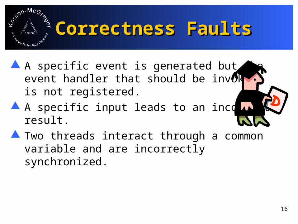
Correctness FaultsCorrectness Faults
A specific event is generated but the event handler that should be invoked is not registered.
A specific input leads to an incorrect result.
Two threads interact through a common variable and are incorrectly synchronized.
17
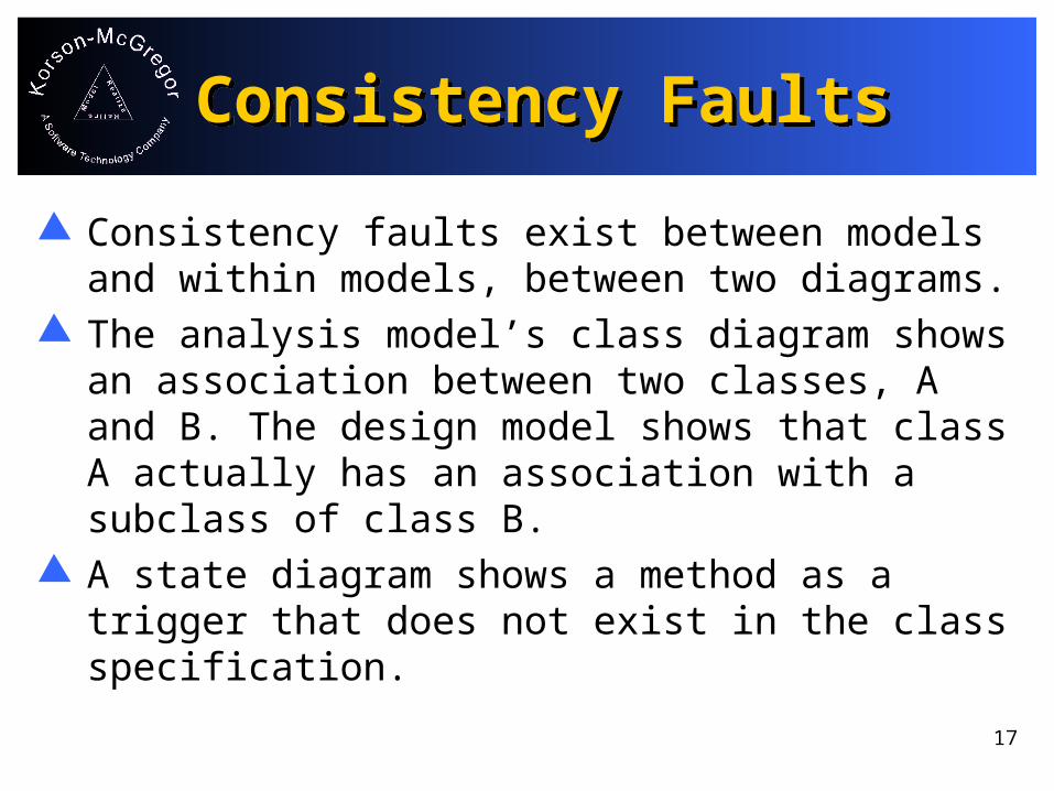
Consistency FaultsConsistency Faults
Consistency faults exist between models and within models, between two diagrams.
The analysis model’s class diagram shows an association between two classes, A and B. The design model shows that class A actually has an association with a subclass of class B.
A state diagram shows a method as a trigger that does not exist in the class specification.

18
Case StudyCase Study
SC
Belgium
O
O
Referee Player
Player
TicTacToe - a distributed, component-based implementation.
Guided Inspection assumes a completed UML model.
Deployment diagram gives context.

19
Use CasesUse Cases
Player selects EXIT from the menu
Player selects a position on the Game Board and clicks
Player reads the message signaling the end of a game
Player has won the game
Player has lost the game
Player has tied the game
Player selects unoccupied position
Player selects occupied position
Player selects when it is not his turn
Player selects when it is his turn
real Human Player
Change Case: The Player selects the SAVE menu option
#1
#2
#3
#4
#5#6
#7
#8 Captures
requirements from a user perspective

20
Framework Class DiagramFramework Class Diagram
Represents the attributes and behaviors of each class
Also relationships between classes

21
Sequence Diagram for setMoveSequence Diagram for setMove
GameBoard Player GameMouse
1: mouseClick
2: setMove 3: setMove Captures interactions of objects via messages
Amount of detail depends on level

22
Design diagram - top of modelDesign diagram - top of model
Same as the framework model but specified for TicTacToe

23
Design diagram - bottomDesign diagram - bottom

24
State DiagramState Diagram
Captures significant configurations of data attributes
Represents sequences of transitions between states
InPlay
PlayCompleted
Won LostTied
Initialized
InPlay
PlayCompleted
Won LostTied
Won LostTied
setMove
Initialized
Exit
reset
Player
NotMyTurn MyTurn
setMove
setMove
25
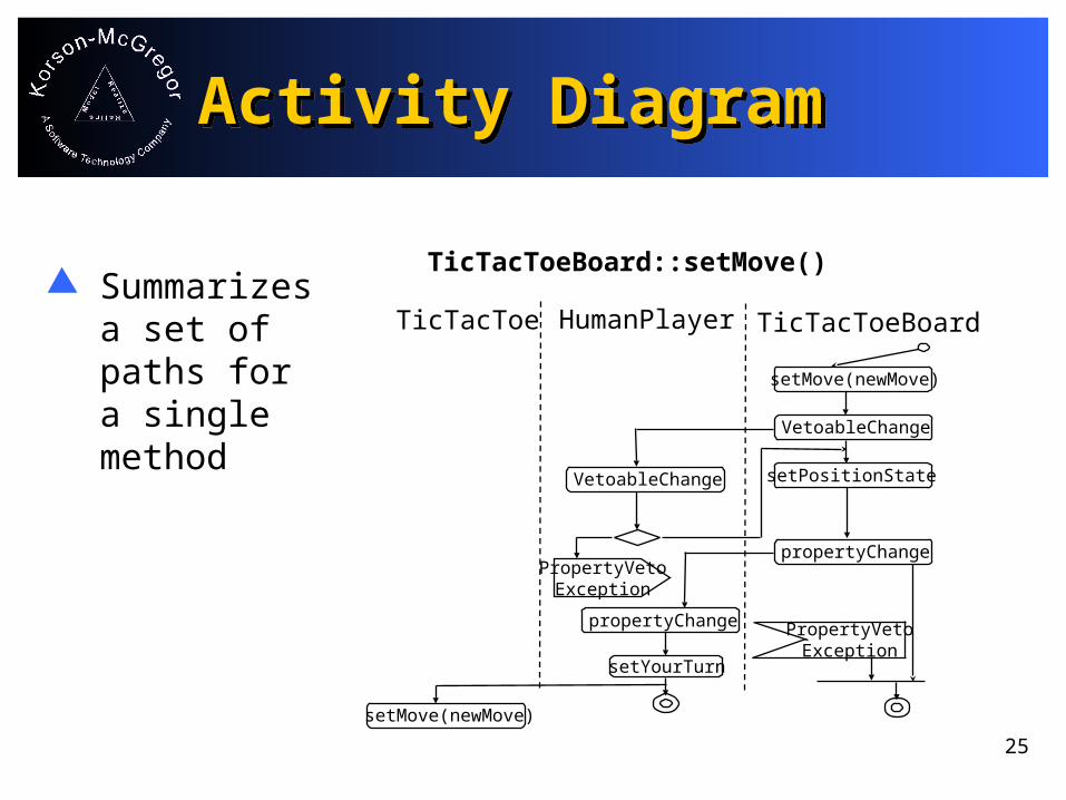
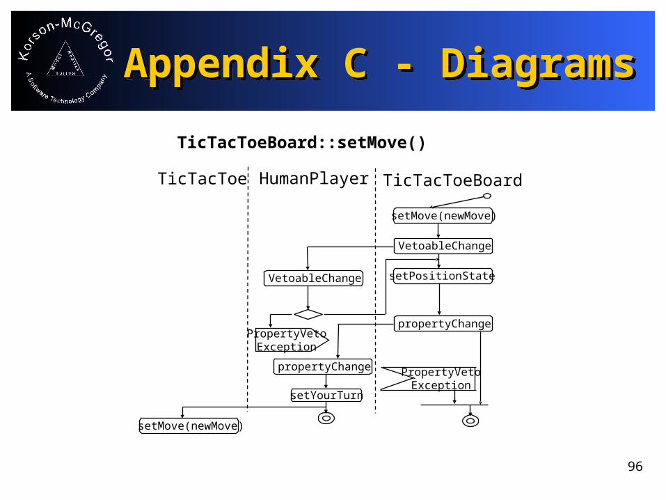
Activity DiagramActivity Diagram
Summarizes a set of paths for a single method
TicTacToeBoard
TicTacToeBoard::setMove()
TicTacToe HumanPlayer
setMove(newMove)
VetoableChange
setPositionState
propertyChange
PropertyVetoException
VetoableChange
propertyChange
PropertyVetoException
setYourTurn
setMove(newMove)

26
ChecklistChecklist
Addresses the syntax of the model
May be replaced with automated syntax checking
Can be completed by individual inspectors prior to the group session
Domain Analysis Model Checklist
Each class box is connected to at least one other class box. ____ Yes ____ No
Each className is a recognized term in the domain. ____ Yes ____ No
Each subclass of a class is a specialization of the original class. ____ Yes ____ No
....

27
ExerciseExercise
Study the materials and diagrams in Appendix C. The tester should study the use case diagram and the two complete use case descriptions. The developer should study the class diagrams, state diagrams and activity diagrams.
As a team. complete the analysis checklist from Appendix D

28
Consistency Between DiagramsConsistency Between Diagrams
Grader Grade
GradeBook
Instructor Student Grader
StudentWork Grade
Create
Create
Assignment
GradeBook
Assign (Assignment)
Submit (Student Work)
Instructor Student Grader
StudentWork Grade
Create
Determine
Assignment
GradeBook
Assign (Assignment)
Submit (Student Work)
Record (Grade)
StudentWorkInstructor Assignment Student
Create
Assign (Assignment)
Create
Submit (Student Work)
Determine
Record (Grade)
29
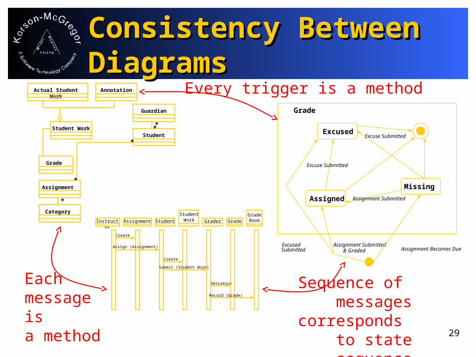
Consistency Between DiagramsConsistency Between Diagrams
Category
Student Work
Actual Student Work Annotation
Guardian
Student
Assignment
Grade
*
*
*
**
Every trigger is a method
Sequence of messages corresponds
to state sequence
Each message is a method
Assigned
Missing
Excused
Grade
Assignment SubmittedExcused Submitted Assignment Becomes Due
Assignment Submitted
& Graded
Excuse Submitted
Excuse Submitted
Instructor Student Grader
StudentWork Grade
Create
Determine
Create
AssignmentGradeBook
Record (Grade)
Assign (Assignment)
Submit (Student Work)

30
Building System Test CasesBuilding System Test Cases
Select a scenario The Player selects an unoccupied slot when it is his
turn. The system responds by displaying the Player’s icon in the appropriate position on the GameBoard.
Write test cases by assigning each variable a specific value. The Player selects the center slot of an empty board,
OR The Player selects the slot in location (1,1) when
slots (0,1) and (2,1) are taken by the opponent and Player has (2,2).

31
ExerciseExercise
Study the materials. The tester should study the use case diagram and the two complete use case descriptions. The developer should study the class diagrams, state diagrams and activity diagrams.
Write test cases from each of the detailed use case scenarios. Remember to include a very specific scenario and the expected results.

32
Building System Test CasesBuilding System Test Cases
For analysis and high-level design models the test cases can be generated from system use cases.
Player selects EXIT from the menu
Player selects a position on the Game Board and clicks
Player reads the message signaling the end of a game
Player has won the game
Player has lost the game
Player has tied the game
Player selects unoccupied position
Player selects occupied position
Player selects when it is not his turn
Player selects when it is his turn
real Human Player
Change Case: The Player selects the SAVE menu option
#1
#2
#3
#4
#5#6
#7
#8

33
High Level Test CaseHigh Level Test Case
Pre: Boards are empty; “X” player’s turn. Trigger: Both players attempt to select cell
(1,1) on their gameBoards at the same time (ODC: Concurrency).
Expected result: Only the gameBoard associated with the “X” player will respond to the event and will display the “X” token of the player in cell (1,1).
34
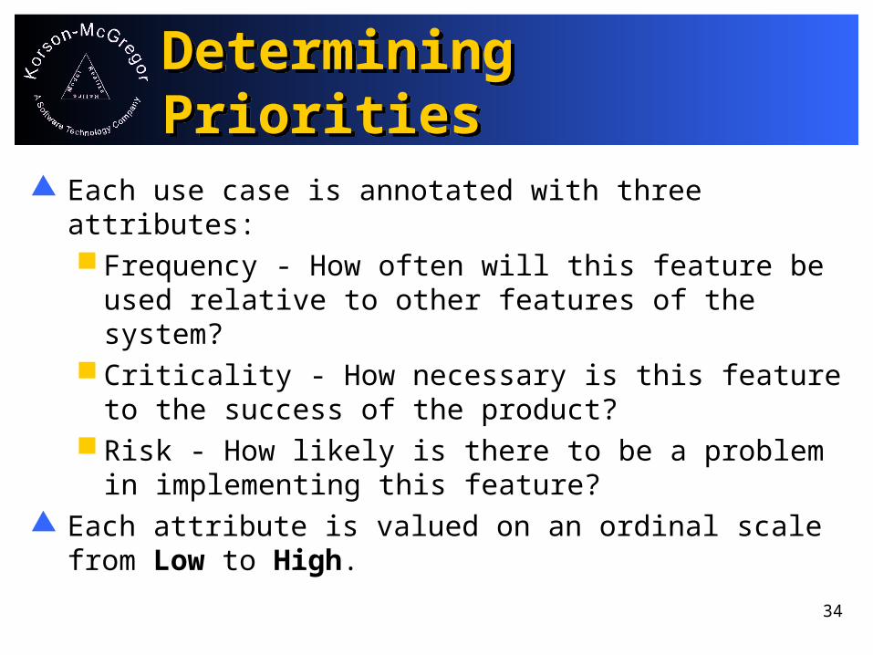
Determining PrioritiesDetermining Priorities
Each use case is annotated with three attributes: Frequency - How often will this feature be
used relative to other features of the system? Criticality - How necessary is this feature to
the success of the product? Risk - How likely is there to be a problem in
implementing this feature? Each attribute is valued on an ordinal scale from
Low to High.

35
Combining Attribute ValuesCombining Attribute Values
Frequency and criticality are both useful for testing: Frequency by itself would correspond to the
operational profile Frequency/criticality identifies the most often used,
most necessary features so that they can be tested the most.
If criticality is HIGH and frequency is LOW: A Conservative combination yields a value of HIGH An Averaging combination yields a value of
MEDIUM

36
PrioritizingPrioritizing
The values could be combined in several ways. By combining frequency and criticality, we get a modified user profile that is useful for determining the number of test cases.
Use case #8 is a change case. It is not yet a requirement so it will not be included.Use CaseFrequencyCriticalityCombined Frequency/Criticality
1 Low Low Low2 Low Medium Medium3 High High4567

37
ExerciseExercise
Use CaseFrequencyCriticalityCombined Frequency/Criticality
1 Low Low Low2 Low Medium Medium3 High High4567
Select a combination strategy. Complete the table.

38
Rationing Test CasesRationing Test Cases
The number of test cases will vary based on the priority of the use case.
Start with the extremes. There are only 9 test cases for use case #3 and 1 for use case #1. This covers these possibilities exhaustively if there are no interactions. These are the HIGH and LOW values in the matrix.
Select a number in between for the medium ones. 3 may be a bit low but there may be insufficient time to do more.

39
Rationing Test CasesRationing Test Cases
The number of test cases will vary based on the priority of the use case.
Use Case #
1 Low Low Low Low 1
2 Low Medium High Medium 3
3 High High Medium High 9
4 Low High Medium Medium 3
5 Low Medium Medium Medium 3
6 Low Medium Medium Medium 3
7 Lows Medium Medium Medium 3
Frequency Criticality Risk CombinedFrequency/Criticality
Number of test cases

40
SamplingSampling
Once the number of test cases is determined, the possible inputs are sampled to construct tests.
Equivalence classes are established for each variable.
Test cases are formed by selecting values from the equivalence classes.
A value for a field is chosen and paired with values of each equivalence class for each variable.

41
Sampling Test CasesSampling Test Cases
Consider use case #2 - selecting an already occupied cell.
There are 9 possible selections that could be made.
Dividing these into equivalence classes Border cells - corners Border cells - in between corners Inner cells
Select one cell from each class - (1,1), (3,2), (2,2)

42
Test PlanningTest Planning
After prioritizing the use cases and rationing the number of test cases, use orthogonal defect classification (ODC) to guide the selection of test cases.
ODC triggers represent common ways failures are caused.
Guided Inspection can use all of the review and inspection triggers and some of the system test and field operation triggers.

43
ODC TriggersODC Triggers
Design conformance Understanding flow Concurrency Backward
Compatibility Lateral Compatibility Rare situations Side effects Document
consistencies
Language dependencies Normal mode Recovery or exception Start up and shut down Software configuration Can not do
Stress Hardware configuration

44
Testing for ...Testing for ...
Completeness - Compare the requirements model with the analysis and design models. Are all of the behaviors required for the requirements present?
Correctness - Focus on whether the results of the detailed examination of the model conform to the expected results. Where there is a variance between the two, both the results and the expected results should be suspect.
Consistency - Compare the representation in each of the diagrams within a model and from one model to another. What are the differences?

45
Inspection SessionInspection Session
Testers guide the inspection by setting the scenario.
Developers “describe” the execution using their knowledge of the classes, but also referring to pre and post-conditions.
Developers record the execution using an appropriate UML diagram.

46
Symbolic ExecutionSymbolic Execution
The tester selects a test case, using the sampling technique.
The tester defines the state of the system at the start of the test case. Label the state of each object at the start of the test as state 0.
The tester initiates the trigger of the use. The developer identifies the message sent and records it on the sequence diagram. If an object changes state because of the message, label the new state, state1.
Repeat until the scenario is completed.
47
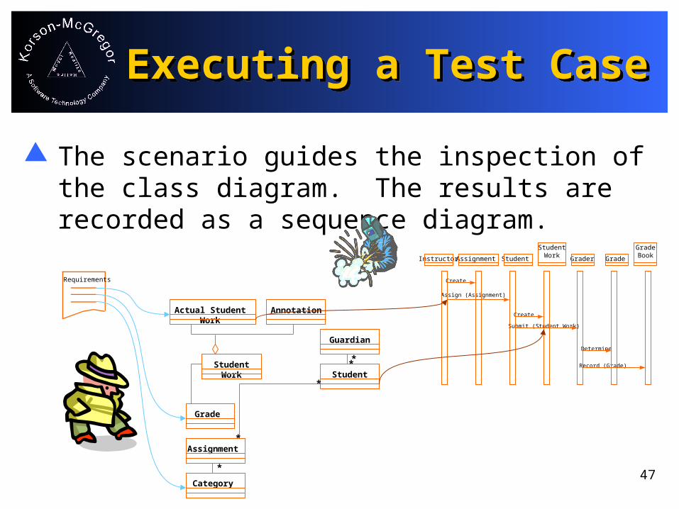
Executing a Test CaseExecuting a Test Case
The scenario guides the inspection of the class diagram. The results are recorded as a sequence diagram.
Category
Student Work
Actual Student Work Annotation
Guardian
Student
Assignment
Grade
*
*
*
**
Instructor Student Grader
StudentWork Grade
Create
Determine
Create
Assignment
GradeBook
Assign (Assignment)
Submit (Student Work)
Record (Grade)
Requirements

48
Analysis of ResultsAnalysis of Results
Completeness - For a message on the SD, is there such a method on the target class? Place a checkmark beside its signature in the class diagram.
Correctness - For the current message, is it a trigger for a transition from the current state? Is the actual ending state the correct ending state? Place a checkmark on the transition.
Consistency - if the current message has parameters, are the types of the objects provided as parameters consistent with the types declared in the class diagram?

49
Detailed Test CaseDetailed Test Case
Test scenario: The Player selects the slot in location (1,1) when slots (0,1) and (2,1) are taken by the opponent and Player has (2,2).
Expected result: The board is refreshed and shows the appropriate icon in the selected cell.
Several steps are needed as pre-conditions for this test case.
These steps can be parts of other test cases. Give attention to sequencing tests to minimize
the effort required for each test.

50
Example Execution of Test CaseExample Execution of Test Case
:TicTacToeBoard :HumanPlayer :TicTacToe :HumanPlayer :TicTacToeBoard
click on(1,1) setMove ((1,1),me)
setMove ((1,1),me)setMove ((1,1),me)
setMove ((1,1),me)

51
Coverage for Test CaseCoverage for Test Case
tiedGamecompletedGame
idle
TicTacToe
1 slot 2 slots 3 slots
4 slots5 slots
6 slots
7 slots 8 slots 9 slots
************ ******
************
******
******
******
* = setMove
exitexit
resetreset
play
playing
*
****** ******
0
1

52
Coverage for Test CaseCoverage for Test Case
Player
Not Connected Connected
NotMyTurn MyTurn
initialize
finalize
setYourTurn(false)
setYourTurn(true)
exit exit
Playing
Won
Lost
Tied
setGameStatus
setGameStatus
setGameStatus
reset
reset
resetexit
setMove
setMove
setMove
1
1
0
0
0

53
Coverage for Test CaseCoverage for Test Case
Game
setMove( )play( )resetGame( )
<<abstract>>
1..*
Player
orb : Orbtoken : intgameStatus : intplayerNo : intremoteGame : RemoteGame
setMove( )initialize( )wonGame( )lostGame( )drawGame( )hasWon( )checkPosition( )isYourTurn( )
<<abstract>>
*
GameBoard
gameStatus : intplayerID : intposition : GameBoardPosition[]
setMove( )handleWindowEvent( )GameBoard( )gameBoardMouseEvent( )setMove( )
(from GUI)
<<abstract>>
54
ExerciseExercise
Use the diagrams on the previous pages plus the class documentation to execute (draw a sequence diagram) one of your test cases.
Evaluate the results of the symbolic execution using the three criteria.

55
ExerciseExercise
Complete the test report from Appendix E. Completeness
Did the class diagram contain all of the classes necessary for representing the scenario?
Was there a relationship for every message that was sent?
Correctness Was the sequence of state transitions correct? Was each relationship that was used in the scenario the correct
relationship?
Consistency Did the steps in the use case match those in the design? Are the state transitions consistent with the pre and post
conditions?
56
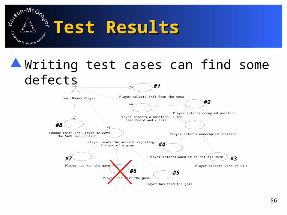
Test ResultsTest Results
Writing test cases can find some defects
Player selects EXIT from the menu
Player selects a position on the Game Board and clicks
Player reads the message signaling the end of a game
Player has won the game
Player has lost the game
Player has tied the game
Player selects unoccupied position
Player selects occupied position
Player selects when it is not his turn
Player selects when it is his turn
real Human Player
Change Case: The Player selects the SAVE menu option
#1
#2
#3
#4
#5#6
#7
#8

57
Coverage AnalysisCoverage Analysis
Is there at least one scenario for each use case?
Player selects EXIT from the menu
Player selects a position on the Game Board and clicks
Player reads the message signaling the end of a game
Player has won the game
Player has lost the game
Player has tied the game
Player selects unoccupied position
Player selects occupied position
Player selects when it is not his turn
Player selects when it is his turn
real Human Player
Change Case: The Player selects the SAVE menu option
GameBoard HumanPlayer GameRemoteGameStub
Mouse
1: mouseClick
2: setMove 3: setMove4: setMove
GameBoard HumanPlayer GameRemoteGameStub
Mouse
1: mouseClick
2: setMove 3: setMove4: setMove
GameBoard HumanPlayer GameRemoteGameStub
Mouse
1: mouseClick
2: setMove 3: setMove4: setMove
GameBoard HumanPlayer GameRemoteGameStub
Mouse
1: mouseClick
2: setMove 3: setMove4: setMove

58
Coverage AnalysisCoverage Analysis
Has every class been touched by a test case? If not why not?
Are there important methods that have not been used?
Game
setMove()play()resetGame()
<<abstract>>
RemotePlayer
resetGame()isYourTurn()wonGame()lostGame()tiedGame()yourTurn()
<<idl interface>>
RemoteGame
setMove()resetGame()
<<idl interface>>
Move
newPosition : PositionplayerID : int
<<idl struct>>
Player
orb : Orbtoken : intgameStatus : intplayerNo : intremoteGame : RemoteGame
setMove()initialize()wonGame()lostGame()drawGame()hasWon()checkPosition()isYourTurn()
<<abstract>>
1..*1..*
GameBoard
gameStatus : intplayerID : intposition : GameBoardPosition[]
setMove()handleWindowEvent()GameBoard()gameBoardMouseEvent()setMove()
(from GUI)
<<abstract>>
**
CurrentState
state : int[] = {}
<<idl struct>>

59
Coverage AnalysisCoverage Analysis
Has every important state of every important class been used in a scenario?
If not, what scenario would reach this state?
Player
Not Connected Connected
NotMyTurn MyTurn
initialize
finalize
setYourTurn(false)
setYourTurn(true)
exit exit
Playing
Won
Lost
Tied
setGameStatus
setGameStatus
setGameStatus
reset
reset
resetexit

60
Additional CriteriaAdditional Criteria
The 3 C’s are just a beginning. Every model should achieve these properties, but there are other properties we may wish our system to posses. These include portability, extensibility, and other “ilities”.
If the project has a goal of producing extensible software, we can construct test cases to explore this.
Use the Change Case from the use case diagram to write test cases. Execute and evaluate using the Guided Inspection technique.

61
Exercise - ExtensibilityExercise - Extensibility
Scenario: The system will be extended to provide save and load capabilities.
What interfaces must be changed? What external resources are needed? Is this a reasonable amount of effort? Should
the architecture be changed now to facilitate change later?
What other types of scenarios might result in very different amounts of effort?

62
ExtensibilityExtensibility
Both remote interfaces must be changed to have save and load methods. Game Player
A flat file is needed. This is a reasonable amount of effort. No
change to the architecture will make this any easier.
63
Evaluation of Guided InspectionEvaluation of Guided Inspection
Data to collect Number of defects detected Number of person hours
Evaluation Yield = defects/person hour Effectiveness =
“defects found during inspection”/total defects

64
Trade-offsTrade-offs
Companies have reported that it costs as much as 100 times more to repair a defect at system test time as it would to repair at analysis time.
While guided inspection is a person intensive technique, even the early expenditure of considerable resources can still result in a net savings over the full project life cycle.

65
ConclusionConclusion
The system has been analyzed from three perspectives: correctness, completeness and consistency.
Correctness has been evaluated for each test case. The team has identified “design failures” that would have eventually resulted in code faults.
When sufficient test coverage has been achieved, the team can evaluate the completeness of the design.
The consistency of the system has been evaluated test case by test case.

66
ThanksThanks
On behalf of Korson-McGregor, thank you for attending this session.
Additional material is available on our web site:
www.korson-mcgregor.com My e-mail address is:
Please keep in touch if there is anything I can do for you.
67
Appendix A - Use Cases Supporting the Case Study
Appendix A - Use Cases Supporting the Case Study
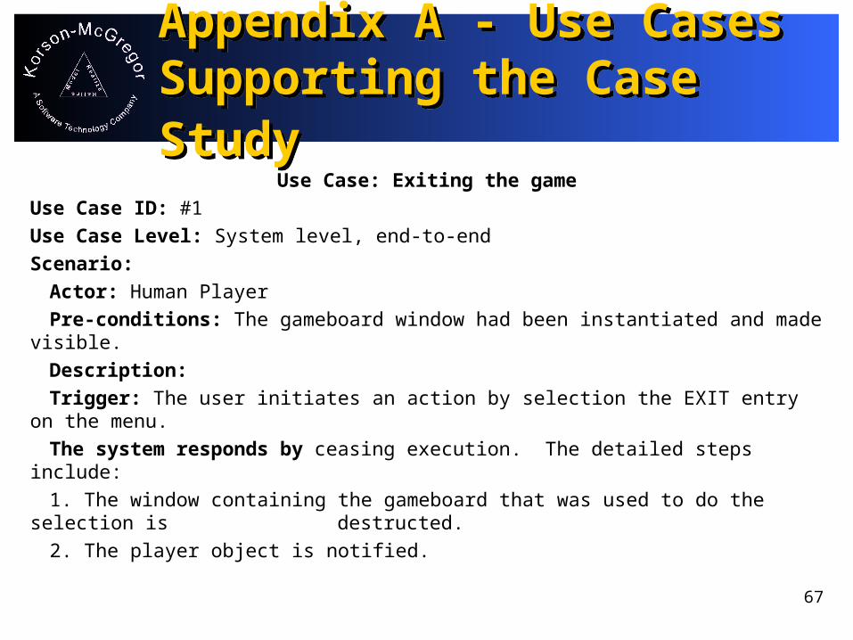
Use Case: Exiting the gameUse Case ID: #1Use Case Level: System level, end-to-endScenario:
Actor: Human PlayerPre-conditions: The gameboard window had been instantiated and made
visible.Description:Trigger: The user initiates an action by selection the EXIT entry on the
menu.The system responds by ceasing execution. The detailed steps include:1. The window containing the gameboard that was used to do the selection
is destructed.2. The player object is notified.
68
Appendix A - Use Cases Supporting the Case Study
Appendix A - Use Cases Supporting the Case Study
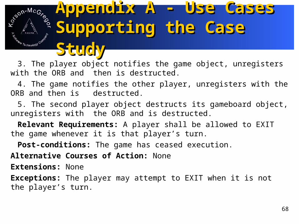
3. The player object notifies the game object, unregisters with the ORB and then is destructed.
4. The game notifies the other player, unregisters with the ORB and then is destructed.
5. The second player object destructs its gameboard object, unregisters with the ORB and is destructed.
Relevant Requirements: A player shall be allowed to EXIT the game whenever it is that player’s turn.
Post-conditions: The game has ceased execution.Alternative Courses of Action: NoneExtensions: NoneExceptions: The player may attempt to EXIT when it is not the player’s turn.

69
Appendix A - Use Cases Supporting the Case Study
Appendix A - Use Cases Supporting the Case Study
Concurrent Uses: None at this timeRelated Use Cases: NoneDecision SupportFrequency: Low - This happens at most once in each execution.Criticality: Low - A CTRL-C will also terminate the game.Risk: Low - This is a standard windowing operation.Modification HistoryOwner: John D. McGregorInitiation Date: 01/15/99Data Last Modified: 05/24/99

70
Appendix A - Use Cases Supporting the Case Study
Appendix A - Use Cases Supporting the Case Study
Use Case: Making a legal moveUse Case ID: #3Use Case Level: System level, end-to-endScenario:
Actor: Human PlayerPre-conditions: A player object has been notified that it is the turn of
that player.Description:
Trigger: The user initiates an action by performing a mouse button release while the cursor is within the bounds of a cell on the gameboard.
The system responds by:1. Mapping the mouse button release to the appropriate cell in the
gameboard.

71
Appendix A - Use Cases Supporting the Case Study
Appendix A - Use Cases Supporting the Case Study
2. Recording the player who now “owns” the cell.3. Redisplaying the gameboard using the appropriate icon in each cell.4. The selection is propagated through the system to the other
gameboard which is also updated.Relevant Requirements: The system shall provide a means by which
players can make a move using a graphical representation of the gameboard.
Post-conditions: The icon assigned to the player is now displayed in the cell where the mouse button release occurred and the cell is now considered to be occupied.Alternative Courses of Action: NoneExtensions: NoneExceptions: The selected cell may be occupied. See that use case for details.

72
Appendix A - Use Cases Supporting the Case Study
Appendix A - Use Cases Supporting the Case Study
Concurrent Uses: No other actions are currently possible concurrent to this use. However, the only prohibited action would be the other player making a move at the same time.Related Use Cases: Use case #TBA that describes the system action when the selected cell is occupied.Decision SupportFrequency: High - This is the most frequent use.Criticality: High - This is the most critical use.Risk: Low - This is handling of a mouse event that occurs frequently.Modification HistoryOwner: John D. McGregorInitiation Date: 01/15/99Data Last Modified: 05/24/99

73
Appendix B - Guided Inspection Process Definition
Appendix B - Guided Inspection Process Definition
Goal: To identify defects in artifacts created during the analysis and design phases of software construction.
Steps in the Process: Define the scope of the Guided Inspection Identify the basis model(s) from which the material
being inspected was created Assemble the Guided Inspection team Define a sampling plan and coverage criteria Create test cases from the bases Apply the checklists and tests to the material

74
Appendix B - Guided Inspection Process Definition
Appendix B - Guided Inspection Process Definition
Gather and analyze test results Report and feedback
Detailed Step Descriptions: Define the scope of the Guided Inspection.
Inputs: The project’s position in the life cycle The material produced by the project (UML models, plans,
use cases)
Outputs: A specific set of diagrams and documents that will be the
basis for the evaluation

75
Appendix B - Guided Inspection Process Definition
Appendix B - Guided Inspection Process Definition
Method: Define the scope of the Guided Inspection to be the set of
deliverables from a phase of the development process. Use the development process information to identify the deliverables that will be produced by the phase of interest.
Example: The project has just completed the domain analysis phase.
The development process defines the deliverable from this phase as a UML model containing domain-level use cases, static information such as class diagrams, and dynamic information such as sequence and state diagrams. The Guided Inspection will evaluate this model.
76
Appendix B - Guided Inspection Process Definition
Appendix B - Guided Inspection Process Definition
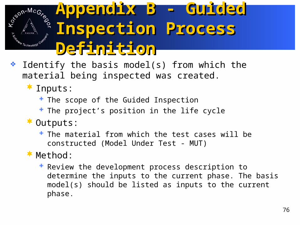
Identify the basis model(s) from which the material being inspected was created. Inputs:
The scope of the Guided Inspection The project’s position in the life cycle
Outputs: The material from which the test cases will be
constructed (Model Under Test - MUT)
Method: Review the development process description to
determine the inputs to the current phase. The basis model(s) should be listed as inputs to the current phase.

77
Appendix B - Guided Inspection Process Definition
Appendix B - Guided Inspection Process Definition
Example: The inputs to the domain analysis phase is the
“knowledge of experts familiar with the domain”. These mental models are the basis models for this Guided Inspection.
Assemble the Guided Inspection team. Inputs:
The scope of the Guided Inspection Available personnel
Outputs: A set of participants and their roles

78
Appendix B - Guided Inspection Process Definition
Appendix B - Guided Inspection Process Definition
Method: Assign persons to fill one of three categories of roles:
Administrative, Participant in creating the model to be tested, or Objective observer of the model to be testing. Choose the objective observers from the customers of the model to be tested and the participants in the creation of the basis model.
Example: Since the model to be tested is a domain analysis model and
the basis model is the mental models of the domain experts, the objective observers can be selected from other domain experts and/or from application analysts. The creation participants are members of the domain modeling team. The administrative personnel can perhaps come from other interested parties or an office that provides support for conducting Guided Inspections.

79
Appendix B - Guided Inspection Process Definition
Appendix B - Guided Inspection Process Definition
Define a sampling plan and coverage criteria. Inputs:
The project’s quality plan
Outputs: A plan for how test cases will be selected A description of what parts of the MUT will be covered
Method: Identify important elements of this MUT. Estimate the
effort required to involve all of these in the Guided Inspection. If there are too many to cover, use information such as the RISK section of the use cases or the judgement of experts to prioritize the elements.
80
Appendix B - Guided Inspection Process Definition
Appendix B - Guided Inspection Process Definition
Example: In a domain model there are static and dynamic models as
well as use cases. At least one test case should be created for each use case. There should be sufficient test cases to take every “major” entity through all of its visible states.
Create test cases from the bases. Inputs:
The sampling plan MUT
Outputs: A set of test cases
81
Appendix B - Guided Inspection Process Definition
Appendix B - Guided Inspection Process Definition
Method: Obtain a scenario from the basis model. Determine the
pre-conditions and inputs that are required to place the system in the correct state and to begin the test. Present the scenario to the “oracle” to determine the results expected from the test scenario. Complete a test case description for each test case.
Example: A different domain expert than the one who supported
the model creation would be asked to supply scenarios that correspond to uses of the system. The experts also provide what they would consider an acceptable response.

82
Appendix B - Guided Inspection Process Definition
Appendix B - Guided Inspection Process Definition
Apply the checklist and tests to the material. Inputs:
Checklist for the type of model being inspected Set of test cases MUT
Outputs: Set of test results Completed checklist
83
Appendix B - Guided Inspection Process Definition
Appendix B - Guided Inspection Process Definition
Method: Apply the test cases to the MUT using the most specific
technique available. For UML models is a static environment, such as Rational Rose, an interactive simulation session in which the Creators play the role of the model elements, is the best approach. If the MUT is represented by an executable prototype, then the test cases are mapped onto this system and executed.
Example: The domain analysis model is a static UML model. A simulation
session is conducted with the Observers feeding test cases to the Creators. The Creators provide details of how the test scenario would be processed through the model. Sequence diagrams are used to document the execution of each test case. Use agreed upon symbols or colors to mark each element that is touched by a test case.

84
Appendix B - Guided Inspection Process Definition
Appendix B - Guided Inspection Process Definition
Gather and analyze test results and coverage. Inputs:
Test results in the form of sequence diagrams and pass/fail decisions
The marked-up model
Outputs: Statistics on percentage of pass/fail Categorization of the results Defect catalogs and defect reports A judgement of the quality of the MUT and the tests

85
Appendix B - Guided Inspection Process Definition
Appendix B - Guided Inspection Process Definition
Method: Begin by counting the number of test cases that passed and
how many have failed. Compare this ratio to other Guided Inspections that have been conducted in the organization. Compute the percentage of each type of element that has been used in executing the test cases. Use the marked-up model as the source of this data. Update the defect inventory with information about the failures from this test session.
Categorize the failed test cases. This can often be combined with the previous two tasks by marking paper copies of the model. Follow the sequence diagram for each failed test case and mark each message, class and attribute touched by a failed test case.

86
Appendix B - Guided Inspection Process Definition
Appendix B - Guided Inspection Process Definition
Example: For the domain analysis model we should be able to
report that every use case was the source of at least one test case, that every class in the class diagram was used at least once. Typically on the first pass, some significant states will be missed. This should be noted in the coverage analysis.
Report and feedback. Inputs:
Test results Coverage information

87
Appendix B - Guided Inspection Process Definition
Appendix B - Guided Inspection Process Definition
Outputs: Information on what new tests should be created Test report
Method: Follow the standard format for a test report in your
organization to document the test results and the analyses of those results. If the stated coverage goals are met then the process is complete. If not, use that report to return to step 5 and proceed through the steps to improve the coverage level.
Example: For the domain analysis tests, some elements were found to
be missing from the model. The failing tests might be executed again after the model has been modified.

88
Appendix B - Guided Inspection Process Definition
Appendix B - Guided Inspection Process Definition
Roles in the Process: Administrator
The administrative tasks include running the Guided Inspection sessions, collecting and disseminating the results, and aggregating metrics to measure the quality of the review. In our example, the administrative work could be done by personnel from a central office.
Creator The persons who created the MUT. Depending upon the
form that the model takes, these people may “execute” the symbolic model on the test cases or they may assist in
89
Appendix B - Guided Inspection Process Definition
Appendix B - Guided Inspection Process Definition
Creator - continued translating the test cases into a form that can be
executed with whatever representation of the model is available. In our example, the modelers who created the domain model would be the “creators”.
Observer Persons in this role create the test cases that are
used in the Guided Inspection. In our example, they would be domain experts and preferably experts who were not the source of the information used to create the model initially.
90
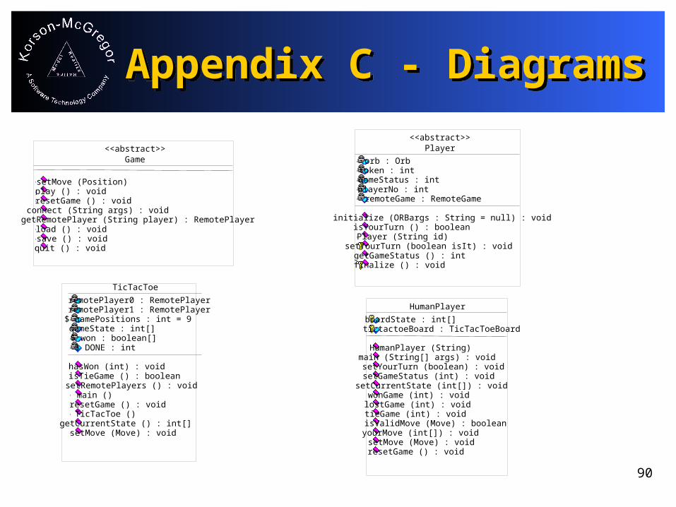
Appendix C - DiagramsAppendix C - DiagramsGame
setMove (Position)play () : voidresetGame () : voidconnect (String args) : voidgetRemotePlayer (String player) : RemotePlayerload () : voidsave () : voidquit () : void
<<abstract>>
TicTacToe
remotePlayer0 : RemotePlayerremotePlayer1 : RemotePlayer$ gamePositions : int = 9gameState : int[]$ won : boolean[]$ DONE : int
hasWon (int) : voidisTieGame () : booleansetRemotePlayers () : voidmain ()resetGame () : voidTicTacToe ()getCurrentState () : int[]setMove (Move) : void
Player
orb : Orbtoken : intgameStatus : intplayerNo : intremoteGame : RemoteGame
initialize (ORBargs : String = null) : voidisYourTurn () : booleanPlayer (String id)
setYourTurn (boolean isIt) : voidgetGameStatus () : intfinalize () : void
<<abstract>>
HumanPlayer
boardState : int[]tictactoeBoard : TicTacToeBoard
HumanPlayer (String)main (String[] args) : voidsetYourTurn (boolean) : voidsetGameStatus (int) : voidsetCurrentState (int[]) : voidwonGame (int) : voidlostGame (int) : voidtieGame (int) : voidisValidMove (Move) : booleanyourMove (int[]) : voidsetMove (Move) : voidresetGame () : void

91
Appendix C - DiagramsAppendix C - Diagrams
GameBoard
gameStatus : intplayerID : intposition : GameBoardPosition[]loadGame : MenuItemsaveGame : MenuItemquitGame : MenuItempositionChanges : PropertyChangeSupportloadChanges : PropertyChangeSupportsaveChanges : PropertyChangeSupportquitChanges : PropertyChangeSupportpositionVetos : VetoableChangeSupportrows : intcolumns : intfileChooser : JFileChooser
setMove () : voidGameBoard ()gameBoardMouseEvent (MouseEvent, int, int) : voidsetMove (int) : voidgameBoardMouseUp (MouseEvent evt, int x, int y) : voidrecalcPositions (int ScreenHeight, int ScreenWidth) : voidpaint (Graphics g) : voidsetPlayerID (int id) : voidgetPlayerID () : intsetGameBoardPositions (int[] positions) : voidsetGameStatus (int status) : voidshowStatus (Graphics g) : voidquitGame () : voidgetGameStatus () : intloadGame () : voidaddPropertyChangeListener (PropertyChangeListener listener) : voidremovePropertyChangeListener (PropertyChangeListener listener) : voidaddVetoableChangeListener (VetoableChangeListener listener) : voidremoveVetoableChangeListener (VetoableChangeListener listener) : voidsaveGame () : void
(from GUI)
<<abstract>>
TicTacToeBoard
not : Imagecross : Image
showTicTacToe () : voidTicTacToeBoard (int)setPositionState (int, int) : voidsetYourTurn (boolean) : void

92
Appendix C - DiagramsAppendix C - Diagrams
Game
PlayCompleted
PlayingInitialized
PlayCompleted
PlayingInitialized
setMovereset
setMoveGame
93
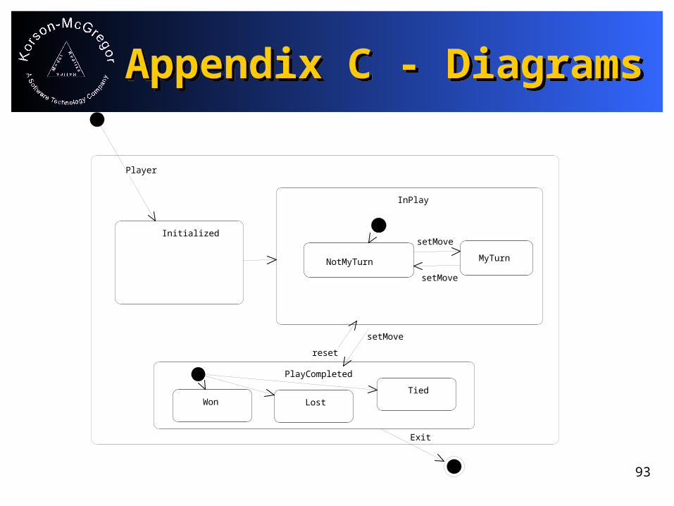
Appendix C - DiagramsAppendix C - Diagrams
InPlay
PlayCompleted
Won LostTied
Initialized
InPlay
PlayCompleted
Won LostTied
Won LostTied
setMove
Initialized
Exit
reset
Player
NotMyTurn MyTurn
setMove
setMove
94
Appendix C - DiagramsAppendix C - Diagrams
:Mouse playerX:Player :TicTacToeplayerXBoard:GameBoard
1: mouseClick(unoccupiedCell)
2: fireVetoableChange
5: firePropertyChange
4: setMove/*asynchronous*/3: setMove
Legal moveLegal move
95
Appendix C - DiagramsAppendix C - Diagrams
:Mouse playerX:Player :TicTacToeplayerXBoard:GameBoard
1: mouseClick(occupiedCell)
2: fireVetoableChange
3: propertyVetoException
Illegal moveIllegal move
96
Appendix C - DiagramsAppendix C - Diagrams
TicTacToeBoard
TicTacToeBoard::setMove()
TicTacToe HumanPlayer
setMove(newMove)
VetoableChange
setPositionState
propertyChange
PropertyVetoException
VetoableChange
propertyChange
PropertyVetoException
setYourTurn
setMove(newMove)
97
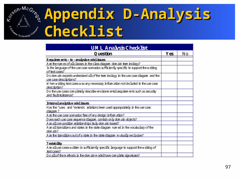
UML Analysis ChecklistQuestion Yes No
Requirements – to - analysis model issuesAre the names of all classes in the class diagram domain terminology?Is the language of the use case scenarios sufficiently specific to support the writingof test cases?Do domain experts understand all of the terminology in the use case diagram and theuse case descriptions?When writing test cases was any necessary information not included in the use casedescription?Do the use cases completely describe environmental requirements such as securityand fault-tolerance?
Internal analysis model issuesHas the “uses” and “extends” relations been used appropriately in the use casediagram?Are the use case scenarios free of any design information?Does each use case sequence diagram contain only domain objects?Are all composition relationships truly domain-based?Are all transitions and states in the state diagram named in the vocabulary of thedomain?Are the transitions out of a state in the state diagram mutually exclusive?
TestabilityAre all use cases written in sufficiently specific language to support the writing oftest cases?Do all of the methods in the domain model have complete signatures?
Appendix D-Analysis ChecklistAppendix D-Analysis Checklist

98
Appendix D-Architecture ChecklistAppendix D-Architecture Checklist
UML Architecture ChecklistQuestion Yes No
Analysis-to-architecture model issuesDoes each analysis class provide objects to at least one component in thearchitecture?Are critical analysis algorithms contained in the minimum number of components?
Internal architecture model issuesAre there fewer messages between objects in different components in thearchitecture than between objects in the same component?Are all existing architectural interfaces included in the model?

99
Appendix D - Detailed Design ChecklistAppendix D - Detailed Design Checklist
UML Detailed Design ChecklistQuestion Yes No
Analysis – to – design model issuesAre all classes in the analysis model that are not in the design model outside thescope of the application?Are all the states in the analysis model statecharts also states in the statechartdiagrams in the design model?Are the sequences of messages in all design-level sequence diagrams the same,even though additional messages may have been inserted between the analysis-levelmessages.
Internal design model issuesAre all associations shown with no navigation information truly bi-directional?Are all composition relationships shown as uni-directional?Is every sequence diagram a subset of some activity diagram?Does every message sent in an interaction diagram appear as a method in the publicinterface of the class of the receiving object?Does every message sent in an interaction diagram go to the logically appropriateobject?Are the transitions out of a state in the state diagram mutually exclusive?Do all state machines, except for perpetual objects, contain initial and final states?Are all public modifier methods represented as transitions on each state even if theyonly result in a self-loop back.?Is there a sequence diagram for each post-condition clause of each method thatcorresponds to use cases that meet the frequency/criticality threshold?Are all messages shown correctly as synchronous or asynchronous?Do the number of forks and joins balance in every activity diagram?

100
Appendix E - Test ReportAppendix E - Test Report
UML Analysis-level Test Case ReportQuestion If Yes, list
the testcase Ids
No
Did the test cases written by the testing domain experts identify additional usecases not found in the current diagram?Did any of the test cases written by testing domain experts contradict theexisting use case descriptions?Did the testing domain experts disagree with any of the results expected to beproduced by any of the use case?Did the test cases written by the testing domain experts identify any additionalstates for any of the class in the domain model?Did any test case lead to discussion of a quality attribute that is not captured inthe use case?Did any test case use a trigger not included in the use case description?Was any test case triggered by an actor not included in the use case diagram?

101
Appendix E - Test ReportAppendix E - Test Report
UML Detailed Design-level Test Case ReportQuestion If Yes, list
the testcase ids
No
Did any test case find a discrepancy between the sequence of messages sent insequence diagrams and the sequence shown in the transitions of the appropriatestate model?Did any test case find a pre-condition on a method that could not be checkedusing the methods on the public interface of the class containing the method?Did any test case find a method that needed a pre-condition that was not statedin the method specification?Did any test case result in a final result that is not part of the stated post-condition? Was the result correct?Did any test case find the need to navigate an association in a direction contraryto the model?Did any test case use a number of objects that contradicted the cardinalityshown in the class diagram.Does any object create an object with which it has an association relationshiprather than a composition relationship?