guideline for coal dust explosion prevention and suppression · guideline for coal dust explosion...
TRANSCRIPT
Guideline for coal dust explosionprevention and suppression
MDG 3006 MRT5
Produced by Mine Safety Operations Division,
New South Wales Department of Primary Industries
December 2001
516 High Street Maitland NSW 2320 PO Box 344 Hunter Region Mail Centre NSW 2310
Phone (02) 4931 6666 Fax (02) 4931 6790 Website www.dpi.nsw.gov.au/minesafety
� u i d e l i n e � o r C o a l � u s t �� p l o s i o n � r ev en t i o n A n d S u pp re s s i on
FIRST PUBLISHED DECEMBER 2001
ACKNOWLEDGMENTS
We wish to thank the Coal Safety Advisory Committee for their most welcome support of this publication.
DISCLAIMER
The principles stated in this document are intended as general guidelines only for the assistance of owners and managers in devising safety standards for the working of mines. Owners and managers should rely upon their own advice, skills and experience in applying safety standards to be observed in individual workplaces.
The State of New South Wales and its officers or agents including individual authors or editors will not be held liable for any loss or damage whatsoever (including liability for negligence and consequential losses) suffered by any person acting in reliance or purported reliance upon this Guideline.
© Copyright NSW Department of Mineral Resources
This work is copyright. Apart from any use as permitted under the Copyright Act 1968, no part may be reproduced by any process without prior written permission from the NSW Government. Requests and enquiries concerning reproduction and rights should be sent to the Assistant Director Safety Operations, Department of Mineral Resources.
NSW Department of Mineral Resources Issued: December 2001 MDG 3006 MRT5
� ��
� � �
�
� �
��
�
�
��
�
� u i d e l i n e � o r C o a l u s t p l o s i o n � r ev en t i o n A n d S u pp re s s i on
FOREWORD�
Clauses of the Coal Mines Regulations relating to M� 3006 MRTS Guideline for Coal Dust Explosion Prevention and Suppression are indicated in the References section of the uideline. The epartment of Mineral Resources document M ��3006 MRTS TR Technical Reference Material for Coal Dust Explosion Prevention and Suppression provides technical reference material for the uideline.
This is an Applied uideline. �urther information on the status of an Applied �uideline in the range of OHS instruments is available through the epartment of Mineral Resources Legislation Update Number 2/2001. The range of instruments include:
��Acts of �arliament ��Regulations made under the Act ��Conditions of emption or Approval ��Standards (AS, ISO, I� C) ��Approved Industry Codes of ractice (under the OHS Act) ��Applied Codes, �uidelines or Standards (under clause 14 of the Coal Mines ( �eneral) Regulation 1999) ���ublished �uidelines ���uidance Notes ��Technical Reference documents ��Safety Alerts
The principles stated in this document are intended as general guidelines only for the assistance of owners and managers in devising safety standards for the working of mines. Owners and managers should rely upon their own advice, skills and e �perience in applying safety standards to be observed in individual workplaces.
The State of New South Wales and its officers or agents including individual authors or editors will not be held liable for any loss or damage whatsoever (including liability for negligence and consequential losses) suffered by any person acting in reliance or purported reliance upon this uideline.
The M 3006 MRTS Guideline for Coal Dust Explosion Prevention and Suppression was distributed to industry for consultation and comment through the Coal Safety Advisory Committee.
The epartment of Mineral Resources has a review time set for each �uideline that it publishes. This can be brought forward if required. Input and comment from industry representatives will be much appreciated. The �eedback Sheet at the end of this document can be used to provide input and comment.
R Regan Assistant �irector Safety Operations
NSW Department of Mineral Resources Issued: December 2001 MDG 3006 MRT5 Prepared By: Safety Operations Authorised: R Regan

� u i d e l i n e � o r C o a l � u s t �� p l o s i o n � r ev en t i o n A n d S u pp re s s i on
NSW Department of Mineral Resources Issued: December 2001 MDG 3006 MRT5 Prepared By: Safety Operations Authorised: R Regan
� ��
�
�
� � �
� � �
����
� u i d e l i n e � o r C o a l u s t p l o s i o n � r ev en t i o n A n d S u pp re s s i on
CONTENTS�
�UR�OS� AN� SCO� 1
R���R�NC S 1
COAL �UST �X �LOSION �R��� NTION & SU��R �SSION MANA ��M �NT SYST�M 2
General 2
Record keeping and documentation 2
Training 2
Monitoring, systems audit and review 2
Risk identification and assessment 2
COAL �UST �X �LOSION �R��� NTION & SU��R �SSION - L M NTS AN� CONSI� �RATIONS 4
Design 4
Purchasing/Construction 5
Installation 5
Maintenance 5
Operation 6
Incident review 6
A��� N�IX: CO�Y O� �MR �A� TT NOTIC RESTRICTIONS ON USE OF STONE DUST' - 1 S�� T�MB�R 1999 7
BACK SH� �T 8
NSW Department of Mineral Resources Issued: December 2001 MDG 3006 MRT5 Prepared By: Safety Operations Authorised: R Regan

� u i d e l i n e � o r C o a l � u s t �� p l o s i o n � r ev en t i o n A n d S u pp re s s i on
NSW Department of Mineral Resources Issued: December 2001 MDG 3006 MRT5 Prepared By: Safety Operations Authorised: R Regan
� ��
��
�
�
� u i d e l i n e � o r C o a l u s t p l o s i o n � r ev en t i o n A n d S u pp re s s i on
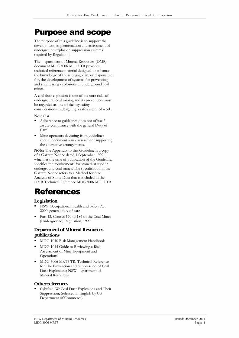
Purpose�nds�spope� The purpose of this guideline is to support the development, implementation and assessment of underground e �plosion suppression systems required by Regulation.
The epartment of Mineral Resources (�MR) document M �3006 MRTS TR provides technical reference material designed to enhance the knowledge of those engaged in, or responsible for, the development of systems for preventing and suppressing e �plosions in underground coal mines.
A coal dust e plosion is one of the core risks of underground coal mining and its prevention must be regarded as one of the key safety considerations in designing a safe system of work.
Note that ��Adherence to guidelines does not of itself
assure compliance with the general �uty of Care
��Mine operators deviating from guidelines should document a risk assessment supporting the alternative arrangements.
Note: The Appendi� to this �uideline is a copy of a �aeette Notice dated 1 September 1999, which, at the time of publication of the �uideline, specifies the requirements for stonedust used in underground coal mines. The specification in the �aeette Notice refers to a Method for Siee Analysis of Stone �ust that is included in the �MR Technical Reference M ��3006 MRTS TR.
Referedpes� Legislation ��NSW Occupational Health and Safety Act
2000, general duty of care ���art 12, Clauses 170 to 186 of the Coal Mines
(Underground) Regulation, 1999
Department of Mineral Resources publications ��M�� 1010 Risk Management Handbook ��M�� 1014 �uide to Reviewing a Risk
Assessment of Mine �quipment and Operations
��M�� 3006 MRTS TR, Technical Reference for The �revention and Suppression of Coal �ust ��plosions; NSW epartment of Mineral Resources
Other references ��Cybulski, W: Coal �ust ��plosions and Their
Suppression; (released in �nglish by US �epartment of Commerce)
NSW Department of Mineral Resources Issued: December 2001 MDG 3006 MRT5 Page: 1
� ��
�
�
� u i d e l i n e � o r C o a l u s t p l o s i o n � r ev en t i o n A n d S u pp re s s i on
Conl�sust� explosiod� prevedtiod��� suppressiod� mndngemedt� system�
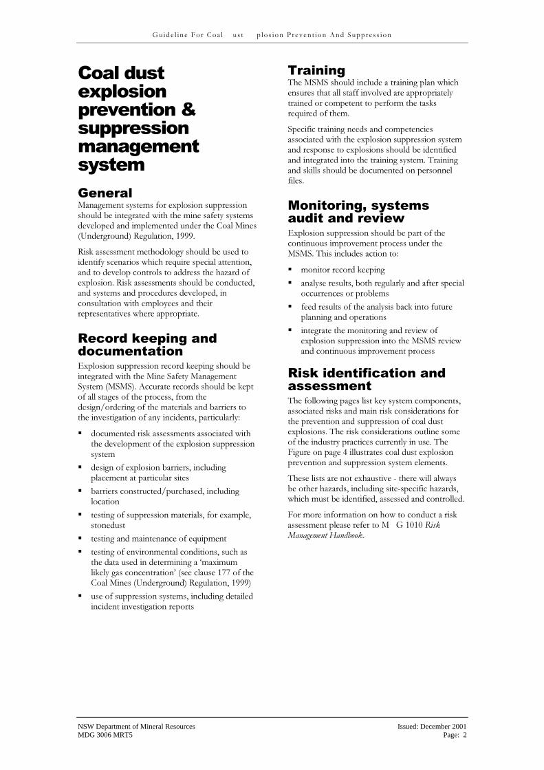
Gedernl Management systems for e�plosion suppression should be integrated with the mine safety systems developed and implemented under the Coal Mines (Underground) Regulation, 1999.
Risk assessment methodology should be used to identify scenarios which require special attention, and to develop controls to address the haeard of e�plosion. Risk assessments should be conducted, and systems and procedures developed, in consultation with employees and their representatives where appropriate.
Repors�keepidg�nds� sopumedtntiod� ��plosion suppression record keeping should be integrated with the Mine Safety Management System (MSMS). Accurate records should be kept of all stages of the process, from the design/ordering of the materials and barriers to the investigation of any incidents, particularly:
��documented risk assessments associated with the development of the e �plosion suppression system
��design of e �plosion barriers, including placement at particular sites
��barriers constructed/purchased, including location
��testing of suppression materials, for e �ample, stonedust
��testing and maintenance of equipment ��testing of environmental conditions, such as
the data used in determining a 'ma�imum likely gas concentration' (see clause 177 of the Coal Mines (Underground) Regulation, 1999)
��use of suppression systems, including detailed incident investigation reports
Trnididg� The MSMS should include a training plan which ensures that all staff involved are appropriately trained or competent to perform the tasks required of them.
Specific training needs and competencies associated with the e�plosion suppression system and response to e�plosions should be identified and integrated into the training system. Training and skills should be documented on personnel files.
Moditoridg,�systems� nusit� nds� review�� ��plosion suppression should be part of the continuous improvement process under the MSMS. This includes action to:
��monitor record keeping ��analyse results, both regularly and after special
occurrences or problems ��feed results of the analysis back into future
planning and operations ��integrate the monitoring and review of
e�plosion suppression into the MSMS review and continuous improvement process
Risk�isedtifipntiod�nds� nssessmedt� The following pages list key system components, associated risks and main risk considerations for the prevention and suppression of coal dust e�plosions. The risk considerations outline some of the industry practices currently in use. The �igure on page 4 illustrates coal dust e�plosion prevention and suppression system elements.
These lists are not e �haustive - there will always be other haeards, including site-specific haeards, which must be identified, assessed and controlled.
�or more information on how to conduct a risk assessment please refer to M � 1010 Risk Management Handbook.
NSW Department of Mineral Resources Issued: December 2001 MDG 3006 MRT5 Page: 2

� ��
Design
Purchasing/ Construction
Installation
Maintenance
Operation
On going
audit
Incident review
� u i d e l i n e � o r C o a l u s t p l o s i o n � r ev en t i o n A n d S u pp re s s i on
COAL DUST EXPLOSION PREVENTION AND SUPPRESSION SYSTEM – ELEMENTS
Design
Purchasing/ Construction
Installation On going
Audit
Maintenance
Incident review Operation
NSW Department of Mineral Resources Issued: December 2001 MDG 3006 MRT5 Page: 3

� ��
� u i d e l i n e � o r C o a l u s t p l o s i o n � r ev en t i o n A n d S u pp re s s i on
Conl�sust� explosiod� prevedtiod��� suppressiod��� elemedts�nds� podsiserntiods�
Desigd� Required outcome Optimum prevention and suppression methods are designed for the mine and each working area. These will minimise the possibility of an e�plosion, and rapidly and effectively suppress an e�plosion should it occur.
Main risks ��inadequate prevention system allows initiation
of an e�plosion
��inadequate stonedusting system
��inappropriate or inadequate barriers, including poor design or positioning of e �plosion barriers, fail to suppress e�plosion
��design inadequately covers high risk areas including conveyor belts and returns from operating panels
Main risk considerations ��competent person designs the mines e �plosion
suppression system taking into account site specific risks
��close attention is paid to prevention measures - ignition control, gas control, dust control
��stonedusting is developed as the first line of defence with passive (and active barriers) forming the last line of defence in the event of an e �plosion
��high risk areas where coal dust is being generated and deposited continually are identified and given special attention to prevent accumulation of float dust1
��stonedusting system is designed using correct principles including: ��stonedust used must comply with
requirements for particle siee and composition
��stonedust is more effective the closer it is to the point of ignition
��stonedust should be applied continuously (for e �ample, by trickle duster) in areas
1 Coal dust, finer than 75 micrometres, deposited upon
previously stonedusted surfaces.
where coal dust is likely to be deposited continuously (e.g. conveyor belt roadways and returns)
��the rate of trickle dusting must be designed to effectively combat float dust deposition by taking into account the rate of deposition of coal dust
��systems should be devised to detect (and remedy) failure in operation of a trickle duster before dangerous quantities of float dust accumulate
��dry stonedust should be used in follow up treatments for surfaces initially coated with stonedust slurry
��stonedusting should cover all surfaces (roof, ribs, floors and structures)
��appropriate selection and use of active e�plosion barriers2 and/or passive e �plosion barriers3, namely: ��distributed stonedust barriers ��distributed water barriers ��concentrated stonedust barriers ��concentrated water barriers ��active barriers
��barriers are selected and designed to take into account: ��capability of responding adequately to
strong and weak e�plosions4
��on-site risks, such as position of conveyor belts or ventilation ducting, and placed so that protection is provided both above and below such obstacles
��placement at the appropriate distance from the face
��the appropriate formation ��appropriate row spacing for distributed
barriers ��sufficient e �tinguishant for the area of the
roadway ��load carrying requirements ��electrical, fire resistance, heat resistance,
e�plosion performance requirements
���storied� barriers are used to protect stationary e�plosion haeards, such as areas in which spontaneous combustion is known or suspected, and where there is no need for
2 A mechanism for dispersing an extinguishing agent which is triggered by the approach of the flame from an explosion. 3 A structure for dispersing an extinguishing agent, usually stonedust or water, which is triggered by the wind blast of an explosion. 4 Explosions at the low end of the speed range, with flame speeds around 30 metres per second (108 kph). These explosions are not ‘weak’ in the amount of damage they can cause.
NSW Department of Mineral Resources Issued: December 2001 MDG 3006 MRT5 Page: 4

� ��
�
�
� u i d e l i n e � o r C o a l u s t p l o s i o n � r ev en t i o n A n d S u pp re s s i on
vehicle traffic to pass ��procedures designed for installation of barriers
as the panel develops ��specifications for stonedust and water barriers
adhered to ��barriers which are a variation on proven
design are e �amined to ensure that the principles of proven design are not invalidated or alternatively the varied design is proven through a testing program
��product information available for design personnel and passed on to installation and maintenance staff, and to those responsible for emergency preparedness
�or more information regarding stonedusting and the design of passive e �plosion barriers, see M�� 3006 MRTS TR, Technical Reference for The �revention and Suppression of Coal �ust ��plosions; NSW �epartment of Mineral Resources.
Purphnsidg/Codstruptiod� Required outcome ��plosion suppression equipment and materials, including passive or active e plosion barriers and their component parts, are purchased and/or constructed in accord with the design.
Main risks ��inappropriate machinery for stonedusting
purchased (for e�ample, incapable of adequately spreading stonedust within time constraints of production)
��inappropriate barriers purchased (for e �ample, troughs not approved for use with rigid support) leading to poor suppression of e�plosions
��barriers (for e ample, stone dust trays) constructed inappropriately leading to poor suppression of e�plosions
Main risk considerations ��consultative process between installers and
designers of suppression system ��purchasing/procurement based on detailed
design specifications ��construction based on detailed design
specifications ��construction supervised by competent persons
Idstnllntiod� Required outcome ��plosion barriers and stonedusting machinery are installed correctly in accordance with design, leading to successful suppression of e �plosions.
Main risks ��unsuccessful suppression of e� plosions
through ��inappropriate siting of stonedusting
equipment (such as trickle dusters) ��incorrect installation of e�plosion barriers ��incorrect or inadequate
installation/loading of suppression materials (that is, stonedust or water)
��installation creates secondary risks, such as injury caused by barriers
Main risk considerations ��system for consultation with design and
purchasing staff prior to installation ��installation follows design criteria ��barriers are installed early in the life of a panel,
and moved or e �tended with development ��barriers are loaded appropriately
Mnidtedndpe�� Required outcome Stonedusting systems and e �plosion barriers are kept in optimum condition.
Main risks ��float dust (coal dust) coating stone dust and
roadways, particularly around conveyor belts and on return roadways
��stone dust caking ��stonedusting machinery malfunctioning ��passive e�plosion barriers becoming
ineffective due to deterioration
��constituents of active e�plosion barriers becoming ineffective due to deterioration
��ignition risks increased due to poor maintenance of equipment
��freshly mined areas not kept wet prior to stonedusting
Main risk considerations ��system for regular inspection, testing and
maintenance of conditions and equipment ��Continuous stonedusting to address float dust
risk
NSW Department of Mineral Resources Issued: December 2001 MDG 3006 MRT5 Page: 5

� ��
� u i d e l i n e � o r C o a l u s t p l o s i o n � r ev en t i o n A n d S u pp re s s i on
Operntiod� Required outcome If an e�plosion occurs, e�plosion barriers operate effectively, preventing propagation of the e�plosion.
Main risks ��As above in Maintenance
Main risk considerations ��As above in Maintenance
Idpisedt�review� Required outcome ��plosion suppression systems are continuously improved.
Main risks ��inadequate investigation of incident ��inadequate sharing of incident investigation
results with all relevant staff ��inadequate use of information from review by
design, procurement, installation and maintenance staff
Main risk considerations ��established system for incident review,
including policies, procedures, accountabilities and communication objectives
��systems for design, procurement, installation and maintenance take into account prior e�perience
NSW Department of Mineral Resources Issued: December 2001 MDG 3006 MRT5 Page: 6

� ��
�
�
�
�
� u i d e l i n e � o r C o a l u s t p l o s i o n � r ev en t i o n A n d S u pp re s s i on
Appedsix:�Copy�Of�DMR�Gneette�Notipe� 'Restrictions On Use Of Stone Dust' �1�9� September�9999�
DEPARTMENT OF MINERAL RESOURCES
COAL MINES REGULATION ACT 1982
COAL MINES (UNDERGROUND) REGULATION 1999
�ile No: C99/0691 ate: 1 September 1999
RESTRICTIONS ON USE OF STONE DUST
By this notice the following requirements are specified for stone dust for the purpose of clause 179 (1) of the Coal Mines (Underground) Regulation 1999:
(a) It must not contain more than 3% by mass of free silica as determined by the Method for �ree Silica in Limestone �ust in '�uidelines for Coal �ust ��plosion, revention and Suppression', publication M��3006 MRTS, published by the �epartment of Mineral Resources; and
(b) It is of such fineness as determined by the Method for Siee Analysis of Stone �ust in '�uidelines for Coal �ust ��plosion, revention and Suppression', publication M��3006 MRTS, published by the �epartment of Mineral Resources; that
(i). not less than 9S% by mass must pass through a 2S0 micrometre sieve, and
(ii). of the dry dust which passes through a 2S0 micrometre sieve, not less than 60% by mass and not more than 80% by mass, must pass through a 7S micrometre sieve.
aul Healey Chief Inspector of Coal Mines
NSW Department of Mineral Resources Issued: December 2001 MDG 3006 MRT5 Contact: C Ellis Authorised: R Regan Next Review: 2006

� ��
� u i d e l i n e � o r C o a l u s t p l o s i o n � r ev en t i o n A n d S u pp re s s i on
Feesbnpk�sheet� Your comment on this �uideline will be very helpful in reviewing and improving the document.
�lease copy and complete the �eedback Sheet and return it to:
Steve Stewart Mine Safety and Environment NSW Department of Mineral Resources PO Box 536 St Leonards NSW 1590 Fax: (02) 99018584
How did you use, or intend to use, this Guideline?
What do you find most useful about the Guideline?
What do you find least useful?
Do you have any suggested changes to the Guideline?
Thank you for completing and returning this �eedback Sheet.
NSW Department of Mineral Resources Issued: December 2001 MDG 3006 MRT5 Contact: C Ellis Authorised: R Regan Next Review: 2006

TECHNICAL REFERENCE MDG 3006 MRT 5
DOC NAME: BARGUID2.DOC FILE NUMBER: C98/2498 ISSUE A: REVISION 2 ISSUED: NOVEMBER 2001
MDG 3006 MRT 5 TR
TECHNICAL REFERENCE MATERIAL
FOR
COAL DUST EXPLOSION PREVENTION AND SUPPRESSION
Prepared for: Chief Inspector of Coal Mines Department of Mineral Resources
Date completed: November 2001
DOC NAME: BARGUID2.DOC ISSUE A: REVISION 2
TECHNICAL REFERENCE MDG 3006 MRT 5
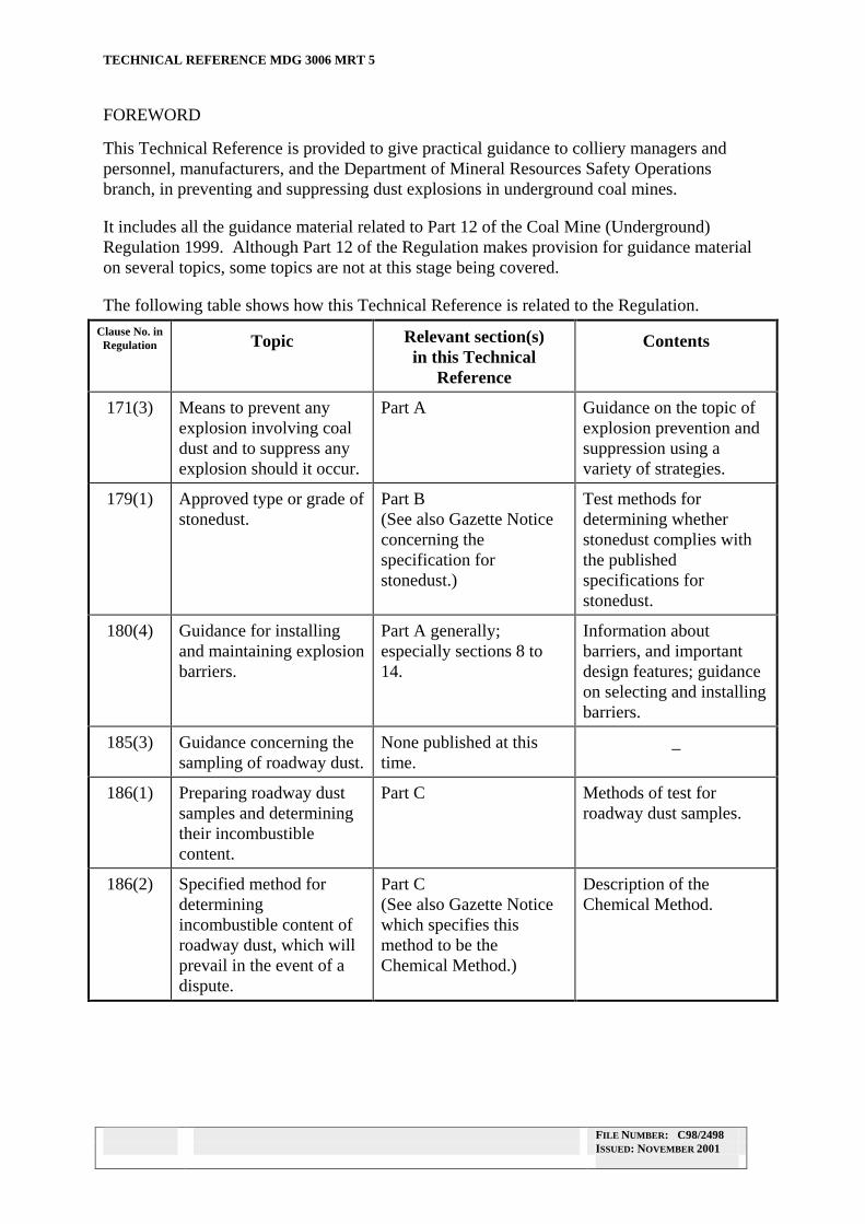
FOREWORD
This Technical Reference is provided to give practical guidance to colliery managers and personnel, manufacturers, and the Department of Mineral Resources Safety Operations branch, in preventing and suppressing dust explosions in underground coal mines.
It includes all the guidance material related to Part 12 of the Coal Mine (Underground) Regulation 1999. Although Part 12 of the Regulation makes provision for guidance material on several topics, some topics are not at this stage being covered.
The following table shows how this Technical Reference is related to the Regulation.
Clause No. in Regulation Topic Relevant section(s)
in this Technical Reference
Contents
171(3) Means to prevent any explosion involving coal dust and to suppress any explosion should it occur.
Part A Guidance on the topic of explosion prevention and suppression using a variety of strategies.
179(1) Approved type or grade of stonedust.
Part B (See also Gazette Notice concerning the specification for stonedust.)
Test methods for determining whether stonedust complies with the published specifications for stonedust.
180(4) Guidance for installing and maintaining explosion barriers.
Part A generally; especially sections 8 to 14.
Information about barriers, and important design features; guidance on selecting and installing barriers.
185(3) Guidance concerning the sampling of roadway dust.
None published at this time.
_
186(1) Preparing roadway dust samples and determining their incombustible content.
Part C Methods of test for roadway dust samples.
186(2) Specified method for determining incombustible content of roadway dust, which will prevail in the event of a dispute.
Part C (See also Gazette Notice which specifies this method to be the Chemical Method.)
Description of the Chemical Method.
FILE NUMBER: C98/2498 ISSUED: NOVEMBER 2001

DOC NAME: BARGUID2.DOC ISSUE A: REVISION 2
TECHNICAL REFERENCE MDG 3006 MRT 5
The Technical Reference is in three distinct parts:
• Part A deals with general information about coal dust explosions, means of preventing and suppressing explosions, and explosion barriers. It covers all the material being produced in relation to Part 12 of the Regulation, except those specific topics which are covered by Parts B and C;
• Part B is intended to assist managers, manufacturers, suppliers and the Department of Mineral Resources Safety Operations branch when assessing types or grades of stonedust as being fit for use in underground coal mines for prevention of dust explosions.
The material covers the test methods for determining that a particular type of stonedust complies with the regulatory requirements for sieve analysis and content of quartz. These requirements are to ensure that the dust in use will not be harmful to the health of mine workers, and that the dust is of an appropriate size to suppress an explosion.
The methods have been tested in the laboratories of Mine Safety Technical Services, Department of Mineral Resources.
• Part C is provided to assist managers, mine staff and the Department of Mineral Resources Safety Operations branch when testing roadway dust samples from underground coal mines to ensure that roadway dusts comply with the requirements for minimum incombustible content in the applicable regulations.
Four different methods are described. All may be used, but in case of dispute the Chemical Method for Roadway Dust is the “specified method” and determinations by this method will prevail.
The Technical Reference may in time be expanded to include further topics, as necessary.
Comments on any aspect of this Technical Reference should be submitted to:
Mr Graham Fawcett Manager Mine Safety Technical Services Department of Mineral Resources
P.O. Box 76 Lidcombe NSW 2141
Fax (02) 9646 3224
FILE NUMBER: C98/2498 ISSUED: NOVEMBER 2001
DOC NAME: BARGUID2.DOC ISSUE A: REVISION 2
TECHNICAL REFERENCE MDG 3006 MRT 5
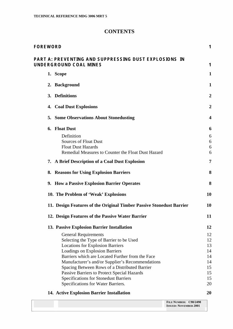
CONTENTS
FOREWORD 1
PART A: PREVENTING AND SUPPRESSING DUST EXPLOSIONS IN UNDERGROUND COAL MINES 1
1. Scope 1
2. Background 1
3. Definitions 2
4. Coal Dust Explosions 2
5. Some Observations About Stonedusting 4
6. Float Dust 6
Definition 6 Sources of Float Dust 6 Float Dust Hazards 6 Remedial Measures to Counter the Float Dust Hazard 6
7. A Brief Description of a Coal Dust Explosion 7
8. Reasons for Using Explosion Barriers 8
9. How a Passive Explosion Barrier Operates 8
10. The Problem of ‘Weak’ Explosions 10
11. Design Features of the Original Timber Passive Stonedust Barrier 10
12. Design Features of the Passive Water Barrier 11
13. Passive Explosion Barrier Installation 12
General Requirements 12 Selecting the Type of Barrier to be Used 12 Locations for Explosion Barriers 13 Loadings on Explosion Barriers 14 Barriers which are Located Further from the Face 14 Manufacturer’s and/or Supplier’s Recommendations 14 Spacing Between Rows of a Distributed Barrier 15 Passive Barriers to Protect Special Hazards 15 Specifications for Stonedust Barriers 15 Specifications for Water Barriers. 20
14. Active Explosion Barrier Installation 20
FILE NUMBER: C98/2498 ISSUED: NOVEMBER 2001
DOC NAME: BARGUID2.DOC ISSUE A: REVISION 2
TECHNICAL REFERENCE MDG 3006 MRT 5
PART B: TESTS FOR ASSESSING STONEDUST 21
1. INTRODUCTION 21
1.1 Purpose and Scope 21 1.2 Relationship with Regulations 21
2. METHOD FOR SIZE ANALYSIS OF STONEDUST 22
3 METHOD FOR QUARTZ IN LIMESTONEDUST 24
3.1. Materials Required 24 3.2. Procedure 25 3.3. Calculations 28
PART C: TEST METHODS FOR COAL MINE ROADWAY DUST 29
INTRODUCTION 29
1.1 Purpose and Scope 29 1.2 Relationship with Regulations 29
ANALYSIS METHOD 1 - CHEMICAL METHOD FOR ROADWAY DUST 30
ANALYSIS METHOD 2 - VOLUMETRIC METHOD FOR ROADWAY DUST 32
ANALYSIS METHOD 3 - COAL ASH INCOMBUSTIBLES ANALYSER METHOD FOR ROADWAY DUST 34
ANALYSIS METHOD 4 - COLORIMETRIC METHOD FOR ROADWAY DUST 36
FILE NUMBER: C98/2498 ISSUED: NOVEMBER 2001

DOC NAME: BARGUID2.DOC ISSUE: A REVISION 2
TECHNICAL REFERENCE MDG 3006 MRT 5
PART A: PREVENTING AND SUPPRESSING DUST EXPLOSIONS IN UNDERGROUND COAL MINES
1. SCOPE
This Part of the Technical Reference aims to provide a basis of understanding for those involved in protecting underground coal mines against explosions. It outlines the principles of explosion prevention and suppression, the characteristics of a coal dust explosion, and the use and limitations of stonedust and water. The principles of operation of passive and active explosion barriers are explained.
It describes classical passive barriers using water and stonedust, and shows the important features which allow these proven designs to operate effectively. This aims to equip colliery staff to assess whether their barriers are designed and constructed to operate as intended.
Active barriers are only touched on briefly, as there are several types of these, and none is yet in use here. The principles are outlined.
2. BACKGROUND
An underground explosion can have catastrophic consequences for all those working in a mine, and preventing explosions must always be a high priority in underground mining operations.
Several areas of control should be used, each of which will reduce the likelihood or severity of an explosion:
Ignition control ��eliminate (as far as possible) sources of ignition;
Gas control ��minimise the methane which can enter the ventilated roadways (for example, by pre
drainage); ��control accumulations of methane in roadways by effective ventilation;
Dust control ��minimise the production of coal dust;
��prevent coal dust from accumulating in the roadways (for example, by using dust scrubbing systems, or washing down surfaces);
��reduce the ability of coal dust to be raised into the air by a gas ignition (for example, by keeping working places wet).
Despite all these measures, sometimes a breakdown in protection occurs and an explosion may still result. Stonedust provides the next line of defence. If sufficient is used, it makes the dust mixture incapable of propagating an explosion. It is used most effectively near the point of origin of an explosion, for reasons which will be explained later.
FILE NUMBER: C98/2498 ISSUED: NOVEMBER 2001 PAGE 1 OF 37
DOC NAME: BARGUID2.DOC ISSUE: A REVISION 2
TECHNICAL REFERENCE MDG 3006 MRT 5
For stonedust to be effective, coal dust must be prevented from forming a layer over the top of the stonedust, since it is possible for an explosion to selectively remove the overlying coal dust from the surface. In return roadways, this requires that stonedust be applied continuously (e.g. by trickle duster) rather than periodically.
Despite all the above measures, including stonedusting, explosions may still occur. This can be seen as a possibility in those places where coal dust is being generated or deposited continually, so that at any time stonedusting may be inadequate. The high production rates in modern mines accentuate this problem.
We would have to include two main areas of the mine: conveyor belt roadways, and returns from operating panels. There may be other areas which also fall into this category. Passive explosion barriers provide a last defence against an explosion propagating throughout the mine. To be effective, they need to be designed, constructed and maintained correctly.
The manner of installation can vary, usually with the intention of making installation easier. Often the variations also have the effect of reducing the ability of the barrier to suppress an explosion.
Traditional timber passive stonedust barriers have not been used in New South Wales coal mines for some time. However other designs are derived from them, and so their principles are described in some detail.
At the time of writing, active explosion barriers have yet to be used in New South Wales. They function differently from passive barriers, and each type needs to be assessed on its own merits.
3. DEFINITIONS
The definitions in the Regulation have the meaning defined in the Regulation. In addition to those definitions:
Concentrated Barrier means either a stonedust or water barrier in which a series of loaded shelves are spaced at intervals of up to 3 metres.
Distributed Barrier means either a stonedust or water barrier in which a series of loaded shelves are more widely spaced than in a concentrated barrier, and further described in this Technical Reference.
Regulation means the Coal Mines (Underground) Regulation 1999.
Storied Barrier means a barrier in which shelves are constructed one above the other across the roadway. It may consist of several rows of such structures, and is used adjacent to sealed areas in which heatings and fires have occurred. It is further described in the section “Passive Barriers to Protect Special Hazards”.
4. COAL DUST EXPLOSIONS
FILE NUMBER: C98/2498 ISSUED: NOVEMBER 2001 PAGE 2 OF 37

DOC NAME: BARGUID2.DOC ISSUE: A REVISION 2
TECHNICAL REFERENCE MDG 3006 MRT 5
It is beyond the purpose of this Technical Reference to provide a detailed understanding of the behaviour of coal dust explosions. For a thorough treatment of the subject, the reader is referred to the large amount of research carried out at the following establishments, and others:
• Buxton in the UK, published in a series of papers by the SMRE (Safety-in-Mines Research Establishment), later the Health and Safety Executive;
• Bruceton and then Lake Lynn in the US, published in a series of papers by the US Bureau of Mines and MSHA (Mine Safety and Health Administration);
• Experimental Mine Barbara in Poland. This work was consolidated by Cybulski into a book “Coal Dust Explosions and their Suppression”, published in Polish in 1973. It was translated into English at the instigation of the United States Bureau of Mines;
• Some work is being done using Australian coals, by bodies such as SIMTARS in Queensland and ACIRL Ltd. Reports are being made available as this work progresses.
A coal dust explosion may develop if these factors occur simultaneously:
1. sufficient oxygen to sustain combustion;
2. dust of a composition which is capable of sustaining an explosion;
3. a means of raising sufficient of the dust into the air; and
4. a means of igniting the dust.
Each of these four deserves a few comments.
1. Ventilated roadways will almost always contain sufficient oxygen for combustion.
Goaf areas may become inert: by the replacement of air with emitted methane; or by the consumption of oxygen in the normal slow oxidation processes of the coal - thereby producing carbon dioxide. Inert gases may be deliberately introduced to inhibit oxidation in an unventilated part of a mine, as a means of controlling spontaneous combustion of coal.
2. The significant properties of dust include its (dry ash-free) volatile content, its fineness, its moisture content, and its (solid) incombustible content. The major experimental work has been conducted using coals from the Northern Hemisphere. Earlier experiments suggested that the dry ash-free volatile content of the coal dust had a marked effect on the incombustible required to prevent an explosion. Later work has shown that with strong initiators the effect of volatile content is not as great. Coals with volatile contents below about 10 to 12 percent have been found incapable of propagating a dust explosion. Above about 22% there is not much change in explosibility. Moisture helps to reduce the explosibility of the dust, and also makes it harder to disperse into the air.
Work undertaken on Australian coals to date suggests that these coals are more explosive than those from the Northern Hemisphere. Further work is being done on this topic.
It is important to understand that a strong initiator may be capable of causing an explosion in dust which would not explode with a weaker initiator. A length of roadway with untreated coal dust in it becomes part of the initiator, as it allows an
FILE NUMBER: C98/2498 ISSUED: NOVEMBER 2001 PAGE 3 OF 37

DOC NAME: BARGUID2.DOC ISSUE: A REVISION 2
TECHNICAL REFERENCE MDG 3006 MRT 5
explosion to develop in strength before attempts are made to stop it. Thus stonedust is most effective when it is used close to the point of initiation.
3. Some sort of substantial air blast is usually needed to raise dust into the air. The most common source is an ignition of methane. Shotfiring used to be another common initiator for dust explosions, and precautions need to be taken when explosives are used underground.
Wet coal dust can be involved in an explosion if the initial blast is strong enough. Explosions involving coal dust which is wet but which contains no other added incombustible can be extremely strong. A commonly used test regards dust as safe if it is so wet that water can be squeezed from it.
4. Both methane ignitions and explosives are capable, not only of raising dust, but simultaneously igniting it. That is why they have been by far the main initiators of dust explosions throughout the history of coal mining.
Direct ignitions of coal dust are possible but highly unlikely. Events such as a blown-out cable do not usually generate sufficient blast to raise a dense cloud of coal dust.
5. SOME OBSERVATIONS ABOUT STONEDUSTING
1. As mentioned above, stonedust is most effective when used close to the point of initiation of an explosion. There are several reasons for this:
• Lower levels of stonedust are required in order to stop an explosion in its early stages than after it has developed into a strong explosion.
• If an area is well stonedusted, a gas ignition may involve negligible coal dust, and so be confined to a small area.
• Miners frequently survive gas explosions; they rarely survive explosions in which coal dust has a major involvement.
• Suppressing an explosion at its source minimises the quantity of carbon monoxide produced. The combustion in a gas explosion may be relatively ‘clean’, producing little carbon monoxide, while coal dust explosions usually produce massive concentrations of carbon monoxide - up to 5% or 50,000ppm. (This is because methane explosions are usually ‘lean’ in fuel, while coal dust explosions are usually ‘fuel rich’.) Historically, most of the miners who have died in coal dust explosions have been killed by carbon monoxide.
• The blast from an explosion travels ahead of the flame, and usually more quickly. So as an explosion flame travels further, the blast from it is acting over a rapidly increasing area - much greater than that travelled by the flame. Unless the flame is extinguished early, damage is likely to disrupt ventilation controls such as stoppings over a wide area, exposing those in the area to the carbon monoxide from the explosion, with little or no incoming fresh air.
2. Stonedust can be very effective in preventing or stopping a coal dust explosion. However the stonedust needs to be either mixed with the coal dust, or lying on top of it. Where stonedust has a layer of coal dust on it, it is possible for an explosion to propagate by removing the overlying coal dust. (The surface of stonedust can harden
FILE NUMBER: C98/2498 ISSUED: NOVEMBER 2001 PAGE 4 OF 37

DOC NAME: BARGUID2.DOC ISSUE: A REVISION 2
TECHNICAL REFERENCE MDG 3006 MRT 5
with moisture, and coal dust is only half the density of stonedust.) In returns, where coal dust is being deposited continuously, stonedust needs to be applied continuously (e.g. by trickle duster).
3. The particles of stonedust should be within the correct size range. If much coarse dust is present, the dust will not adhere to surfaces when it is applied. Instead it will tend to blast surfaces. And the coarse particles are much less effective in suppressing an explosion. The principle seems to be that the ‘particle’ size of an extinguishant must be at least as small as the ‘particle’ size of the fuel. So stonedust should be of a similar fineness to the coal dust, or finer.
But it has been found that very fine limestone has a tendency to cake when exposed to moist air. For this reason there is a limit placed on the fineness of stonedust.
4. An explosion can travel in a roadway where there is a substantial strip of untreated coal dust running along the floor. It is therefore not sufficient to stonedust one side of a roadway, or to neglect the surfaces behind a brattice or on one side of a conveyor belt.
5. Untreated coal dust on the floor may be counteracted by stonedust on the ribs and other surfaces. The reverse does not apply: untreated coal dust on the ribs is not neutralised by stonedust on the floor. Thus it is important to stonedust all surfaces - roof, ribs (including behind brattice), floor and structures.
6. Stonedust can be applied in the form of a slurry. Research has shown that it forms a harder surface which does not disperse readily enough to suppress an explosion. It may be a useful initial treatment, as it can be used in intake roadways with people working on the return side, and will bind the underlying coal dust. But the firm surface may in time accumulate a layer of coal dust, and follow-up treatments with dry dust will be necessary.
7. Mining machines with dust scrubber systems remove a great deal of the dust from surfaces in a roadway. There is no doubt that removing much of the dust is a major contribution to safety. The question has been raised: “Is there is enough dust left to propagate an explosion?”
There is a minimum quantity of dust required for an explosion. The quantity calculates to about the thickness of a sheet of paper or less. There is a difficulty in determining whether this much dust remains in a roadway, as a sampling brush will always leave some behind. The safe position is to assume that there is enough dust to be a danger, and to apply stonedust. But with so little coal dust, little stonedust will be required to treat it.
At present, dust scrubber systems are not available for longwalls.
8. Methane in the air adds to the fuel available for a dust explosion to propagate. If some methane is normally present in the air in a roadway, extra stonedust is needed to suppress a dust explosion. However stonedust cannot suppress a gas explosion (where methane is present at a concentration in its flammable range of 5 to 15% by volume).
FILE NUMBER: C98/2498 ISSUED: NOVEMBER 2001 PAGE 5 OF 37

DOC NAME: BARGUID2.DOC ISSUE: A REVISION 2
TECHNICAL REFERENCE MDG 3006 MRT 5
6. FLOAT DUST
Definition
Float dust means coal dust, finer than 75 micrometres, deposited upon previously stonedusted surfaces.
Sources of Float Dust
The predominant sources of float dust are the mining and transportation of coal. Thus immediate face return airways and belt conveyor roads are the most likely places in which float dust will be deposited. However, as float dust is readily transportable by air currents, dust generated on conveyor roads may not remain confined to that heading and could be deposited in adjoining roadways as well. This phenomenon is particularly noticeable at belt transfers located at the splitting point of ventilating currents.
A third but nonetheless significant source of float dust is the movement of vehicles, particularly on main transport and shuttle car wheeling roads.
Float Dust Hazards
Research has shown that for "light" concentrations of float dust the explosion suppression capacity of any underlying stonedust is not impaired. However, at concentrations above 50 g/m3 float dust will reduce or completely negate the explosion suppression capacity of underlying stonedust.
In practical terms 50 g/m3 relates to float dust concentrations (generally on horizontal surfaces) that:-
• are clearly visible, or
• are thick enough to leave a noticeable indent when making a cross with a person’s finger in the accumulation, or
• leave clear foot prints when a person walks across a hard surface.
The precise measurement of float dust generation and hence deposition associated with mining activity can be achieved by use of certain scientific instruments which are available to the New South Wales coal mining industry. These instruments however require specialised knowledge in their operation and analysis.
Remedial Measures to Counter the Float Dust Hazard
The most effective measure to combat float dust deposition is to continuously intermix stonedust with the dust stream at or close to the dust source (i. e. trickle dusting). The rate at which stonedust needs to be applied is dependent upon several factors, including seam volatile percentage.
FILE NUMBER: C98/2498 ISSUED: NOVEMBER 2001 PAGE 6 OF 37

DOC NAME: BARGUID2.DOC ISSUE: A REVISION 2
TECHNICAL REFERENCE MDG 3006 MRT 5
Unless the specific float dust load generated at a coal face can be reliably determined by a method recognised by the Chief Inspector of Coal Mines and subject to any conditions he may impose then the following stonedust levels need to be continuously inter-mixed with return air, at or close to the face.
Continuous miners - 30 kg/hour Longwalls - 150 kg/hour
In areas where the deposition of float dust can be considered relatively low (some belt roads and transport roads), the float dust hazard may be countered by a combined program of regular trickle dusting and stonedust re-application.
7. A BRIEF DESCRIPTION OF A COAL DUST EXPLOSION
A coal dust explosion travelling along a roadway can be divided into several zones:
1. Ahead of the blast the air is still.
2. As the explosion develops, the front of the blast becomes a ‘shock wave’, similar to a nearby thunderclap or a supersonic ‘boom’ from an aircraft. It travels faster than sound, so it is not possible to hear it coming. The speed of the shock wave begins at about 360m/s for the weakest explosions up to 700m/s for fairly strong ones. In more familiar terms, these speeds are 1,300km/h to 2,500km/h. They can be even higher for extremely strong explosions.
3. The region behind the shock wave, ahead of the flame, experiences a cyclone-force wind. The air is thick with dust which has been scoured from every surface in the roadway. The dust concentration makes the air literally choking to breathe.
Wind speeds range from 30m/s to 450m/s (108km/h to 1,600km/h) for weak to fairly strong explosions. At these wind speeds nothing is safe. Heavy equipment is overturned, wheeled equipment moves, spiral ventilation ducting unravels into ribbons of sheet metal, and anything loose becomes a missile. And it is all in the dark because of the thick dust.
The distance between the shock wave and the flame front increases as the explosion travels further, since the shock wave travels considerably faster than the flame.
4. The flame travels at a speed slightly greater than the wind, but slower than the shock wave. (This means it travels in the dust-laden air, rather than in its own combustion products.) Speeds would range from just over 30m/s to 530m/s (120km/h to 1,900km/h) for weak to fairly strong explosions.
5. Behind the flame the air is relatively still, but very hot. Shortly it will begin to cool and contract, tending to draw gas back. This will cause less violent movements back towards the point of origin of the explosion, followed by a series of decreasing oscillations.
FILE NUMBER: C98/2498 ISSUED: NOVEMBER 2001 PAGE 7 OF 37

DOC NAME: BARGUID2.DOC ISSUE: A REVISION 2
TECHNICAL REFERENCE MDG 3006 MRT 5
8. REASONS FOR USING EXPLOSION BARRIERS
An explosion should be confined to the area in which it is initiated. The alternative to this approach is to attempt to protect the entire mine. Remembering that the protection would need to be adequate for well-developed explosions, incombustible levels of at least 85% would be required throughout the mine. This is believed to be impractical. The better approach, by far, is to concentrate suppression measures close to the likely points of initiation.
It will be apparent from the comments about stonedusting that, while stonedusting is a very effective way of suppressing explosions, there may be circumstances in which it is not totally effective. Two obvious instances of this are:
• roadways in which a conveyor belt is installed, where the coal on the belt and the dust generated by movement and transfer cannot be protected by stonedusting; and
• return roadways, where failure of a trickle duster may allow coal dust generated by mining to form a layer on top of stonedust.
In both these situations additional protection is required as a backup, to make certain that an explosion will not escape into the rest of the mine. At present, this protection should be provided by passive barriers.
There may be other situations which are likely points of initiation of an explosion. These places should be assessed to determine whether adequate protection is provided by stonedusting alone. If not, these should also be given additional protection by barriers.
9. HOW A PASSIVE EXPLOSION BARRIER OPERATES
A passive barrier relies on the fact that the wind blast from an explosion travels ahead of the flame. The energy in the wind blast is used to disperse an extinguishing agent -usually water or stonedust - into the air in the path of the oncoming flame, so that the flame will be extinguished.
There are several important considerations in designing an effective explosion barrier.
1. The barrier must be designed so that it is capable of distributing its load of water or stonedust when struck by the wind blast of an explosion. As explosions vary enormously in their severity, this poses a problem. A strong explosion will easily disrupt a barrier, but a weak explosion may not. Barriers are therefore designed with specific features to improve their ability to operate in weak explosions. These features will be described in more detail in the separate sections dealing with water and stonedust barriers.
2. Timing is a problem. The blast activates the barrier, but the target of the barrier is not the blast: it is the flame. It is not known what the speed of an explosion will be, so it is not possible to know with any accuracy what will be the separation, in time or in distance, between the blast and the flame.
FILE NUMBER: C98/2498 ISSUED: NOVEMBER 2001 PAGE 8 OF 37

DOC NAME: BARGUID2.DOC ISSUE: A REVISION 2
TECHNICAL REFERENCE MDG 3006 MRT 5
The distance of the barrier from the point of initiation can be used as a means of optimising the timing. The barrier takes a finite time to activate. If the barrier is too near the origin of the explosion, the flame may have passed it before the extinguishant is fully released. If it is too far away, the extinguishant may have been dispersed too soon. For this reason, barriers should usually be positioned within certain distances of the face.
One other solution to the problem of timing is the distributed barrier. In this arrangement, the rows of the barrier are spaced well apart. A distributed barrier may not arrest an explosion as quickly as would an ideally-placed concentrated barrier, but it is more likely that some of the rows will be correctly placed to be effective. Thus distributed barriers provide good protection against explosions with a wide range of intensities. They also provide some practical benefits in use.
If a barrier is to be placed at a great distance from a face which it is to protect, it is better to use a stonedust barrier rather than water. This is because the water from a barrier, once dispersed, is not available for suppression. Stonedust remains effective in the roadway. However it is better to place barriers close to the hazard they are protecting.
3. Sufficient extinguishant is required. This leads to a requirement for the total quantity of stonedust on a barrier, which is related to the cross-sectional area of the roadway. For distributed barriers, the spacing of the rows is determined so that the quantity of extinguishant per cubic metre of roadway does not fall below a specified level.
4. The extinguishant from the barrier must be dispersed well enough across the roadway to provide complete protection. Contrary to what we might expect, dust does not quickly disperse sideways in a roadway during an explosion. It is therefore necessary to ensure that the barrier covers most of the width of the roadway, without substantial gaps.
Similarly there is a problem below a conveyor belt where the barrier is mounted above it. Dust or water will certainly fall in the roadway, but it may not ‘wrap around’ a substantial obstacle such as a belt. Ideally, additional protection should be provided below the belt.
A worse problem occurs where a belt is mounted high in a roadway, and the barrier is mounted below it. There is virtually no chance that dust or water will rise and ‘wrap around’ a belt above the barrier.
5. The operation of the barrier must not be impaired by its surroundings or its position. For example, a barrier will be less effective if placed in a cavity in the roof, because the wind blast will largely bypass it.
Similarly, placing a barrier beyond an intersection may make it less able to operate, since an explosion loses intensity at an intersection. (Sometimes however this position is unavoidable.)
FILE NUMBER: C98/2498 ISSUED: NOVEMBER 2001 PAGE 9 OF 37

DOC NAME: BARGUID2.DOC ISSUE: A REVISION 2
TECHNICAL REFERENCE MDG 3006 MRT 5
10. THE PROBLEM OF ‘WEAK’ EXPLOSIONS
Many of the precautions described in the early part of this Technical Reference will help to reduce the intensity of an explosion. However it is possible for a ‘weak’ explosion to propagate.
A ‘weak’ explosion in this context is not weak in terms of the damage it may cause. It refers to explosions at the low end of the speed range, with flame speeds around 30 metres per second - or about 108km/h.
A weak explosion may propagate where reasonable (but inadequate) standards of stonedusting have been maintained. It could also occur where a fine layer of float coal dust overlies stonedust.
The explosion may not gain in intensity in this region, but it may continue to travel. If it manages to bypass other forms of protection (such as barriers) and reach the less protected roadways further from the face, it may then develop into a strong explosion and travel for great distances.
It is therefore essential that a backup protection, such as a barrier, is capable of stopping weak explosions.
11. DESIGN FEATURES OF THE ORIGINAL TIMBER PASSIVE STONEDUST BARRIER
Although the timber stonedust barrier is not now used in NSW mines, the various designs which have been accepted are based on its principles and features. It is therefore appropriate to examine in more detail how it operates.
The design follows those used in the United Kingdom, which were in turn closely modelled on designs developed in Poland. It should be noted that stonedust barriers in some other countries have differed in design, and have been found to be less effective against weak explosions.
• A barrier frame is rectangular, and is made of timber with a height of at least 150mm. Two such timbers form the front and back of the frame, and are fixed by cross-pieces so that the frame measures no more than 200mm from front edge to back edge.
• The frame rests on supports which are rigidly fixed on each side of the roadway, but it is not fixed to the supports. The construction is such that the frame can move off the supports without obstruction.
• Dust boards rest on the frame, but are not fastened to it. They are aligned in the direction of the roadway, and are free to move off the frame in the event of an explosion. The stonedust is piled loosely on the boards.
FILE NUMBER: C98/2498 ISSUED: NOVEMBER 2001 PAGE 10 OF 37

DOC NAME: BARGUID2.DOC ISSUE: A REVISION 2
TECHNICAL REFERENCE MDG 3006 MRT 5
There are three ways in which stonedust can be dispersed into the air from such a barrier:
• it can be eroded (scoured) from the surface by the wind blast passing across it. For this to happen the surface of the dust must be exposed and reasonably powdery.
• the boards can be thrown off the frame. This relies on the boards being loose, and not attached to the frame or each other. This action disperses the dust into the wind blast from the explosion. The movement of the separate boards will assist in distributing the dust. Other designs, in which the dust boards are longer and run across the roadway, are less effective against weak explosions.
• the entire frame can be forced off its supports by the action of the wind blast on the front face of the frame. This relies on the frame being able to move without obstruction in the direction of the wind blast, so that it can move off the supports. This disrupts the entire barrier and disperses the boards and the dust. Its effectiveness is improved by the height of the frame, which exposes a large cross-sectional area to the wind blast. Designs with frames of lower height are less effective against weak explosions.
Some variations on this design have been accepted:
• sheet metal components have replaced timber;
• trays of limited size have replaced dust boards;
• instead of an entire frame sliding on its supports, the principle has been accepted that purlins placed on their edge can ‘roll’ and displace the trays which rest on them.
However, despite these variations, the other features of the design must be retained, both in the design and installation of stonedust barriers. For example, a stonedust barrier using sheet metal purlins in place of a timber frame must have the purlins on their edge. If they were laid flat the barrier would be more stable, but less effective against weak explosions. (Manufacturers of these systems should make the supports in such a way that the purlins cannot be laid flat on them.)
12. DESIGN FEATURES OF THE PASSIVE WATER BARRIER
The troughs used in water barriers are made and tested to a German standard (DIN 21576) dated 1969. This is copied with minor changes in British Coal Specification 733: 1991.
The specification requires troughs to comply with:
• dimensional requirements (so they will fit in their supporting frame but not fall out of it);
• electrical requirements, to ensure that empty troughs stored underground do not present a static spark hazard;
• fire-resistance requirements, to ensure that empty troughs will not continue to support burning if involved in a fire;
• heat-resistance requirements, to ensure that troughs will support their capacity of water and remain in their support for 48 hours with water at temperatures up to 45°C;
FILE NUMBER: C98/2498 ISSUED: NOVEMBER 2001 PAGE 11 OF 37
DOC NAME: BARGUID2.DOC ISSUE: A REVISION 2
TECHNICAL REFERENCE MDG 3006 MRT 5
• explosion performance requirements, which check that the trough disperses water well enough in an explosion of a particular intensity.
Water troughs may be of 80L capacity or 40L capacity. Only the larger ones have been used in NSW, although the smaller ones are reported to be more effective in weak explosions.
Water can be dispersed from a trough in a few ways:
• As the wind blast strikes the front face of the trough, the face is pushed in and water is thrown out of the top. Here it is exposed to the wind blast and broken up into droplets.
• The deformation of the trough should cause the trough to shatter, allowing the water to empty quickly and become entrained as droplets in the wind.
• The trough may fall from the frame. This is a less desirable mode of operation, since the water may remain largely contained in the trough and protected by it.
Water can be a very effective agent for flame suppression. It has a high heat capacity and an extremely high latent heat of vaporisation, and absorbs infra-red radiation. In a flame it absorbs a large amount of heat by first being heated and then by turning to steam. But it is only effective if it is first broken into droplets. This is a difference from stonedust, which is already present as particles.
For the water in a trough to become droplets, it must be exposed to a sufficiently strong wind blast under favourable conditions. To achieve this, the face of the trough and the space above the trough must not be shielded from an oncoming explosion. This presents a problem of adequately supporting the frame without compromising the operation of the trough.
13. PASSIVE EXPLOSION BARRIER INSTALLATION
General Requirements
A barrier must not be installed in a cavity in the roof.
A barrier in a roadway with a conveyor belt must be installed with a major part of the barrier no lower than the top of the belt, so that dust or water can protect coal dust generated from coal on the belt.
Selecting the Type of Barrier to be Used
A manager who is intending to install a barrier made of components supplied by a manufacturer needs to be satisfied that the barrier design is suitable. The barrier design may be a variation of an existing proven design. In this case the variations will need to be carefully examined to ensure that the principles of the proven design are not invalidated.
Alternately, the design may be quite different from proven designs. In this case, the ability of the barrier to suppress a coal dust explosion will need to be demonstrated by a
FILE NUMBER: C98/2498 ISSUED: NOVEMBER 2001 PAGE 12 OF 37

DOC NAME: BARGUID2.DOC ISSUE: A REVISION 2
TECHNICAL REFERENCE MDG 3006 MRT 5
program of testing. The results of the testing programme will then have to be evaluated to confirm their relevance to the conditions in which the barrier will be used.
There are some testing standards for troughs in water barriers, but there is no universal standard or specification for a barrier, and each design will have to be assessed in conjunction with its proposed use.
A barrier commencing within a face zone should be one of the following:
• a distributed stonedust barrier;
• a distributed water barrier;
• a concentrated stonedust barrier; or
• a concentrated water barrier.
For reasons explained earlier, a distributed barrier - stonedust or water - has advantages in its ability to stop explosions having a wide range of intensities. A concentrated barrier should therefore be installed only where there is a convincing case for not installing a distributed barrier.
Locations for Explosion Barriers
The principle in the Regulation is that explosion barriers should be located close to the likely point of initiation of an explosion. This is most commonly the face, but may also be other places identified in the mine. (This section will refer to the face, but should be taken to include other likely places of initiation.)
Accordingly, the concept of replacing a barrier in a face zone with a more distant barrier is not encouraged. It would require an exemption from part of clause 180 of the Regulation. Most likely conditions which would be attached to such an exemption are shown in the section “Barriers which are Located Further from the Face”.
The inbye row of a distributed barrier should be kept as near as possible to the face. It should never be further outbye than 100 metres from the face. It should also never be further outbye than 30 metres from the conveyor belt feeder or bootend in a conveyor roadway, or never further outbye than 30 metres from a trickle duster (where used), auxiliary fan (where used) or the last line of cut-throughs (where no auxiliary ventilation fan is used).
The inbye row of a concentrated barrier should always be kept within 200 metres of the face but not closer than 60 metres to the face.
As a panel develops the first row of a barrier should be installed as soon as there is room for it, consistent with the distances described above. Further rows can be added as the panel develops, until the complete barrier is in place. From here, a distributed barrier can be either moved by ‘leapfrogging’ the last row past the rest, or simply extended by addition of extra rows. A concentrated barrier should be replaced by another before development would leave its inbye row further from the face than this Technical Reference recommends.
FILE NUMBER: C98/2498 ISSUED: NOVEMBER 2001 PAGE 13 OF 37

DOC NAME: BARGUID2.DOC ISSUE: A REVISION 2
TECHNICAL REFERENCE MDG 3006 MRT 5
Where the barrier is different from proven designs, it should be located near the face, in accordance with the recommendations of the manufacturer and/or supplier.
Loadings on Explosion Barriers
For barriers similar to the conventional designs described in this Technical Reference:
• A barrier which commences within the distances set out in the previous section must be loaded with stonedust or water, to not less than 200 kg per square metre of roadway cross-sectional area. This same loading applies to a barrier which is protecting a place other than a face, where the barrier commences within the same distances applicable to a face.
• Where a barrier does not commence within the distances set out in the previous section, it must be loaded with not less than 400 kg per square metre of roadway cross-sectional area.
A barrier of a design which differs significantly from the conventional stonedust and water barriers described in this Technical Reference must be loaded in accordance with the recommendations of the manufacturer and/or suppliers. If it cannot be located near the face as recommended, the manufacturer and/or supplier must be consulted for an increased loading, suitable for the barrier in its intended location. Where a suitable loading cannot be or is not recommended, the loading must be increased to not less than 400 kg per square metre of roadway cross-section.
Barriers which are Located Further from the Face
Where it is proposed to install a barrier of any design at distances which do not comply with those set out in the section “Locations for Explosion Barriers”, an exemption from part of clause 180 of the Regulation will be needed. As mentioned earlier there are conditions which will most likely be attached to any such approval. They are:
• the barrier should be stonedust, rather than water, because a stonedust barrier is better able to suppress explosions at a distance from the point of initiation;
• the loading on a conventional design of barrier must be increased to not less that 400 kg per square metre of roadway cross-section, as described earlier;
• the loading on a barrier which differs from conventional designs must be increased, as described earlier; and
• the incombustible content required in the roadway dust in that roadway near the face must be extended: ∗ to the site of the barrier; and ∗ along the required length of the barrier. (But if the barrier is longer than the loading
requires, the increased incombustible requirement need not apply to the extra length.)
Manufacturer’s and/or Supplier’s Recommendations
Under the Occupational Health and Safety Act 1983 manufacturers and suppliers of plant for use at work have certain obligations. Among these is a duty to “provide or arrange for the provision of, adequate information about the plant or substance to the persons to whom
FILE NUMBER: C98/2498 ISSUED: NOVEMBER 2001 PAGE 14 OF 37

DOC NAME: BARGUID2.DOC ISSUE: A REVISION 2
TECHNICAL REFERENCE MDG 3006 MRT 5
it is supplied to ensure its safe use.” In order to satisfy this duty manufacturers and/or suppliers must have obtained sound empirical or design evidence of the effectiveness of barriers and the conditions necessary to achieve that effectiveness. This should be the basis of recommendations they make and mines are advised to seek evidence from manufacturers and/or suppliers of them having obtained the necessary sound empirical or design evidence. In particular evidence of a successful program of barrier testing, under conditions relevant to our coal mines, might be the minimum evidence which should be made available.
Spacing Between Rows of a Distributed Barrier
The spacing between consecutive rows shall be such that the mass of water or stonedust in the volume of roadway occupied by the barrier, is not less than 1 kg per cubic metre. The following formula may be used:
mass of water or stonedust on each row (kg) Maximum spacing between rows (m) =
cross - sectional area of roadway (m2 )
Passive Barriers to Protect Special Hazards
In roadways adjacent to stationary explosion hazards - such as areas in which spontaneous combustion is known or suspected, and where there is no need for vehicle traffic to pass, a ‘storied’ barrier can provide excellent explosion protection.
This barrier, usually using stonedust, is built with several levels above each other. It may occupy almost the entire roadway width. It consists of several rows of such structures.
Easier access for personnel can be achieved by building the barrier less than the full width of the roadway, but staggering the rows - one row close to the rib on one side, the next row close to the rib on the other side.
Loadings on these barriers should be as in the section “Loadings on Explosion Barriers” in this Technical Reference.
Specifications for Stonedust Barriers
Timber Stonedust Barriers
A timber stonedust barrier shall consist of a series of shelves carrying in total not less than the quantity of stonedust required by this Technical Reference.
Each shelf shall as far as is practicable be constructed and installed that, in the event of any explosion, it may fly without obstruction along the roadway.
Each shelf shall consist of a number of dust boards resting on a frame and shall be constructed in accordance with details contained in this Technical Reference. The frames shall be placed at right angles to the direction of the road and the dust boards parallel to the direction of the road.
No dust board or frame shall be fastened to each other or to any bracket.
FILE NUMBER: C98/2498 ISSUED: NOVEMBER 2001 PAGE 15 OF 37

DOC NAME: BARGUID2.DOC ISSUE: A REVISION 2
TECHNICAL REFERENCE MDG 3006 MRT 5
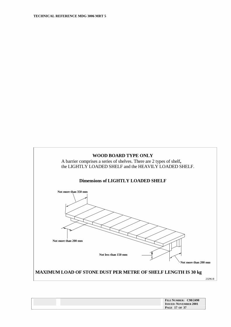
The shelves shall be placed as low as convenient in the upper third of the roadway but in any case, no part of any shelf or the stonedust on it shall be less than 100 millimetres from the roof or sides of the roadway or any roadway support.
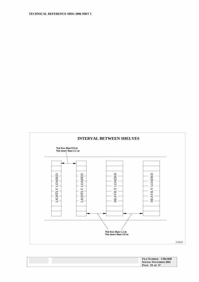
Where the barrier is an isolation barrier, all shelves may be of the heavily loaded type. In all other cases, not less than 1/3 of the shelves shall be of the lightly loaded type.
Where lightly loaded shelves are included in a barrier they shall be placed at the end of the barrier which is nearer to the face or, if the barrier is positioned in relation to some other potential point of initiation of an explosion, at the end which is nearer to that potential point of initiation.
As far as is practicable, the stonedust used on a barrier shall be of a type which will not cake under the normal atmospheric conditions of the length of road in which it is to be used.
To achieve maximum dispersibility, the stonedust shall be piled loosely on the shelves. The stonedust shall neither be tamped down nor placed on the shelves in bags.
Variations on the Timber Stonedust Barrier
Variations on the timber barrier have previously been accepted. The main variations are:
• The components have been made of sheet metal rather then timber.
• The main members of the timber frame have been replaced by ‘C’-shaped purlins. These purlins have not been fastened together, but have sat on edge on rigid supports. Their action is to roll rather than slide on the supports, thereby displacing the remainder of the structure.
• The dust boards have been replaced by trays of limited size. The trays must not be too large, or they will be too heavy to disrupt in a weak explosion.
• The distinction between heavy and light shelves has been removed, so that all trays in a barrier are the same size.
In other respects, the design principles of the timber barrier should be followed closely.
A manager may want to consider whether to guard against the potential hazard of sheet metal trays becoming airborne in an explosion and causing injury. It may be prudent to limit the travel of the trays, without impeding their ability to be dislodged.
FILE NUMBER: C98/2498 ISSUED: NOVEMBER 2001 PAGE 16 OF 37
DOC NAME: BARGUID2.DOC ISSUE: A REVISION 2
TECHNICAL REFERENCE MDG 3006 MRT 5
WOOD BOARD TYPE ONLY A barrier comprises a series of shelves. There are 2 types of shelf, the LIGHTLY LOADED SHELF and the HEAVILY LOADED SHELF.
Dimensions of LIGHTLY LOADED SHELF
Not more than 350 mm
Not more than 200 mm
Not more than 200 mm
Not less than 150 mm
MAXIMUM LOAD OF STONE DUST PER METRE OF SHELF LENGTH IS 30 kg 23296-B
FILE NUMBER: C98/2498 ISSUED: NOVEMBER 2001 PAGE 17 OF 37
DOC NAME: BARGUID2.DOC ISSUE: A REVISION 2
TECHNICAL REFERENCE MDG 3006 MRT 5
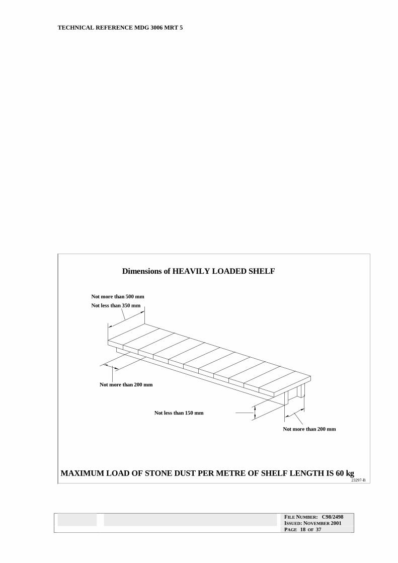
Dimensions of HEAVILY LOADED SHELF
Not more than 500 mm
Not less than 350 mm
Not more than 200 mm
Not more than 200 mm
Not less than 150 mm
MAXIMUM LOAD OF STONE DUST PER METRE OF SHELF LENGTH IS 60 kg 23297-B
FILE NUMBER: C98/2498 ISSUED: NOVEMBER 2001 PAGE 18 OF 37
DOC NAME: BARGUID2.DOC ISSUE: A REVISION 2
TECHNICAL REFERENCE MDG 3006 MRT 5
FILE NUMBER: C98/2498 ISSUED: NOVEMBER 2001 PAGE 19 OF 37
Not less than 0.9 m Not more than 2.1 m
Not less than 1.2 m Not more than 3.0 m
23298-B
INTERVAL BETWEEN SHELVES
LIG
HT
LY
LO
AD
ED
LIG
HT
LY
LO
AD
ED
HE
AV
ILY
LO
AD
ED
HE
AV
ILY
LO
AD
ED
DOC NAME: BARGUID2.DOC ISSUE: A REVISION 2
TECHNICAL REFERENCE MDG 3006 MRT 5
Specifications for Water Barriers.
Water barriers shall consist of troughs filled with water rigidly held in support frames or bearers, and form rows of troughs at right angles to the roadway direction.
The troughs shall be of a type approved for use with rigid support.
The frames shall provide a minimum of shielding to the face of the troughs and the space above the troughs. This is to allow the maximum possible impact of a wind blast on the face of the trough, and on any water which is ejected from the top of the trough.
The frames or bearers shall be supported in the roadway in such a manner that they are not free to move in the direction of the roadway. This is to ensure that in a weak explosion the troughs will be subject to the maximum possible wind blast.
The spacing between rows of troughs shall be not less than 1.5 metres between centres and where the barrier is a distributed barrier, shall be not more than the spacing allowed under the section “Loadings on Explosion Barriers” in this Technical Reference.
The distance between the outside rims of the outside troughs in the same row shall be not less than 65 per cent of the maximum roadway width.
Within a row, the distances between troughs and between the outer troughs and the ribs shall not in total exceed 1.5 metres. The spaces referred to shall be measured at right angles to the roadway direction between trough rims or between trough rims and the rib.
The troughs shall be set up with their long sides at right angles to the roadway direction.
The troughs shall be placed as low as convenient in the upper third of the roadway.
A water barrier shall at all times contain at least the quantity of water required by the section “Loadings on Explosion Barriers” in this Technical Reference.
14. ACTIVE EXPLOSION BARRIER INSTALLATION
Until now active explosion barriers have not been used in New South Wales. There have been several different designs tested in other countries, and they operate in different ways.
Because active barriers sense the approach of the flame, they can more accurately release suppressant into the path of the flame. They do not rely on the blast to activate them. They provide a very rapid release of extinguishant. Some are powered by explosives, others by compressed gas.
Some types were intended as a replacement for passive barriers. Others are intended to be used on or near the heads of mining machines, and would suppress an ignition at a very early stage.
Because of the variety of types, it is necessary that any design which is introduced would have its own set of instructions for installation and placement.
FILE NUMBER: C98/2498 ISSUED: NOVEMBER 2001 PAGE 20 OF 37

DOC NAME: BARGUID2.DOC ISSUE: A REVISION 2
TECHNICAL REFERENCE MDG 3006 MRT 5
PART B: TESTS FOR ASSESSING STONEDUST
1. INTRODUCTION
1.1 Purpose and Scope
In all underground coal mines, the process of preventing dust explosions includes the application of stonedust to roadways. By increasing the inertness of the dust on roof, ribs and floor, the mine operator can reduce or eliminate the danger of dust explosions.
The stonedust used for this purpose must
• have a suitable size distribution to disperse and effectively suppress an explosion
• be relatively low in quartz, so as not to be a hazard to persons in the mine when being applied
The type of dust most usually applied is ground limestone.
The purpose of Part B is to provide methods by which the particle size and quartz content of stonedust may be evaluated, so that it may be assessed for its suitability for use in coal mines.
Application of these tests forms part of the process of implementing “Good Industry Practice” in the use of stonedust to prevent dust explosions in coal mines. It should form part of a comprehensive plan to reduce the risks of fire and explosion in the mine to the lowest feasible level.
1.2 Relationship with Regulations
Under the Coal Mines (Underground) Regulation 1999 the Chief Inspector has issued a notice in the Gazette, specify the requirements for stonedust that is deemed to be “of an approved type or grade”.
As part of the process of implementing the new Regulation, the Chief Inspector will issue a notice specifying:
• the maximum percentage of quartz allowable
• the minimum percentage which shall pass a 250 micrometre sieve, and
• of the dust passing a 250 micrometre sieve, the maximum and minimum percentage passing a 75 micrometre sieve
which are required for any dust to be deemed to be “of an approved type or grade”.
The notice specified the two methods in this Technical Reference as the methods by which compliance with these specifications is to be determined.
FILE NUMBER: C98/2498 ISSUED: NOVEMBER 2001 PAGE 21 OF 37

DOC NAME: BARGUID2.DOC ISSUE: A REVISION 2
TECHNICAL REFERENCE MDG 3006 MRT 5
2. METHOD FOR SIZE ANALYSIS OF STONEDUST
2.1. Scope
This method covers the quantitative determination of the particle size distribution of stonedust finer than 250 micrometres and 75 micrometres by sieve analysis. The determination is to ensure that stonedust complies with the requirements for use in coal mines.
2.2. Apparatus
(a) Standard sieves of aperture 250 micrometres and of aperture 75 micrometres, complying with Australian Standard AS 1152-1973.
(b) Top-loading balance which weighs to 0.01 g
(c) Laboratory air oven maintained at 105°C - 110°C
(d) Desiccator
(e) Clockglasses or dishes.
2.3. Procedure
2.3.1 Preparation of the Sample
The total contents of a standard bag of stonedust is to be coned and quartered and/or riffled to provide a minimum representative sample of 500 g.
2.3.2 Drying of Sample
Weigh about 110 g of air-dried stonedust on the top-loading balance to 0.1 g on to a weighed dish or dishes. Dishes should be of sufficient size and number that the dust is spread to a depth of no more than 1 cm. Place the dishes in an air oven at 105°C - 110°C to dry for at least 1 hour. Remove from air oven and place in desiccator. Allow to cool and then weigh.
Return to air oven for further drying for 1 hour. Remove from air oven and place in desiccator. Allow to cool and then weigh. If the second weight of the sample is within 0.1 g of the first weight then the sample is considered dry. If not, repeat the drying, cooling and weighing until no further loss is observed on weighing.
Calculate the moisture percent as a percentage of the weight of stonedust originally taken.
M − MC = B A ×100
MB
where C is the moisture content of the air-dried dust, expressed as a percentage MB is the mass of dust taken, before drying, expressed in grams MA is the mass of dust after drying, expressed in grams
FILE NUMBER: C98/2498 ISSUED: NOVEMBER 2001 PAGE 22 OF 37
DOC NAME: BARGUID2.DOC ISSUE: A REVISION 2
TECHNICAL REFERENCE MDG 3006 MRT 5
2.3.3 Determination of Dust Content which Passes 250 Micrometres and 75 Micrometres
100g of the sample dried as above is to be sieved by hand or mechanical means to determine the percentage of dust passing nested 250 micrometre and 75 micrometre sieves. The endpoint is considered to have been reached if, during a further 2 minutes’ sieving, not more than 0.1 g passes into the receiver.
Weigh the dust collected in the receiver, and the dust collected on the 250 micrometre test sieve.
2.4. Calculations
Fraction of dry dust passing the 250 micrometre test sieve:
M − MD 250 × 100F250 = MD
Fraction of dry dust passing the 75 micrometre test sieve, as a percentage of dust passing the 250 micrometre test sieve:
MPF = ×10075 M − MD 250
where F250 is the fraction of dry dust which passes the 250 micrometre sieve, expressed as a percentage of the dust taken for sieving,
F75 is the fraction of dry dust which passes the 75 micrometre sieve, expressed as a percentage of the dust which passes the 250 micrometre sieve
MD is the mass of dried dust taken for sieving, expressed in grams MP is the mass of dust collected in the receiver after sieving, expressed in grams M250 is the mass of dust retained on the 250 micrometre sieve, expressed in
grams
2.5. Report
The report of the test must include the following results, each of which may be rounded to the nearest whole number:
(a) The percentage by weight of the dry dust which passes the 250 micrometre test sieve
(b) The percentage by weight of the dry dust which passes the 75 micrometre test sieve, expressed as a percentage of the dust which passes the 250 micrometre test sieve.
FILE NUMBER: C98/2498 ISSUED: NOVEMBER 2001 PAGE 23 OF 37

DOC NAME: BARGUID2.DOC ISSUE: A REVISION 2
TECHNICAL REFERENCE MDG 3006 MRT 5
3 METHOD FOR QUARTZ IN LIMESTONEDUST
This method covers the determination of quartz (also known as free silica) in limestone dust by a combined chemical and infra red spectrophotometric technique.
3.1. Materials Required
3.1.1. For wet chemical stage
weighing dish
spatula
balance brush, camel hair or similar
top-loading balance, readable to 0.001 g
de-ionised water
hydrochloric acid (HCl), 5M (prepared from hydrochloric acid, AR)
2 beakers, 500-mL, Pyrex
clock glass
stirring rod, glass
wash bottle
filter paper, ashless, rapid, (e.g. Whatman No 41), 12.5 cm
filter funnel, glass
drying oven, thermostated
electric muffle furnace capable of 400ºC - (if a temperature-programmable muffle furnace is available, a drying oven is not required)
crucible, fused-silica or platinum, with lid
analytical balance, readable to 0.0001 g
desiccator
3.1.2. Additional for infra red stage
micro-balance, readable to 0.001 mg
mortar and pestle, agate or aluminium oxide, large
mortar and pestle, agate or aluminium oxide, small
ethanol, absolute, AR
potassium bromide (KBr), spectro grade, dried at 105°C
grinding mill (shaking type) (sim. Specamill) (optional)
stainless steel capsule and spheres for mill (optional)
die assembly, stainless steel, 13-mm, for preparing KBr disks
bench press, capable of 10 tonnes force
sample holder, to support 13-mm KBr disks in IR beam
Fourier-transform infra red spectrophotometer (FTIR)
FILE NUMBER: C98/2498 ISSUED: NOVEMBER 2001 PAGE 24 OF 37
DOC NAME: BARGUID2.DOC ISSUE: A REVISION 2
TECHNICAL REFERENCE MDG 3006 MRT 5
3.1.3. For preparation of standards
dish, micro, aluminium spatula, micro quartz, primary standard, A9950 Aus1 quartz, working standard, Kingsgate, acid washed
3.2. Procedure
3.2.1. Wet chemical stage
Thoroughly mix the sample supplied. Sampling systematically from the whole sample, weigh, on the top-loading balance, to the nearest 0.01 g, about 1 g of the stonedust to be tested in a suitable weighing dish. If the percentage of acid-insoluble matter in the sample is approximately known, weigh enough sample to produce about 0.05 g of residue. In this case it may be necessary to use a different size of beaker and a different quantity of hydrochloric acid (HCl) in the chemical dissolution.
Transfer the weighed sample quantitatively to a 500-mL beaker. Moisten with de-ionised water. Add 100 mL of hydrochloric acid (HCl), 5M, while holding a clock glass over the beaker to minimise spattering. Cover and allow to stand for 1 h with occasional stirring. When all effervescence has ceased, rinse any splashings from the underside of the clock glass and the sides of the beaker into the solution. Filter the solution through an ashless filter paper, and quantitatively transfer all the insoluble residue to the filter paper. Rinse the residue on the filter paper with de-ionised water at least three times, to eliminate all traces of acid.
Remove the filter paper from the funnel, fold and place in a crucible. Place the open crucible in a drying oven (or temperature-programmable muffle furnace) at 105ºC for 1 h to dry. Ignite in a muffle furnace (or temperature-programmable muffle furnace) at 400ºC until free of carbon.
Transfer the crucible to a desiccator to cool.
When the crucible is cool (30 min), weigh the crucible with its lid and the residue, to 0.0001 g on the analytical balance. Then transfer the residue to a suitable specimen tube, brushing all material from the crucible and its lid. Cap the tube. Weigh the empty crucible and lid to 0.0001 g on the analytical balance.
Concentration of insoluble residue (percent) A B−
E = × 100 D
where: E = Concentration of insoluble residue, expressed as a percentage A = Mass of crucible + lid + residue, expressed in grams B = Mass of crucible + lid, empty, expressed in grams D = Mass of original sample, expressed in grams
Note: If the percentage of insoluble residue in the stonedust is found to be less than the allowable percentage of free silica in stonedust for approval for underground use, the infra red determination of quartz may be omitted from the procedure.
FILE NUMBER: C98/2498 ISSUED: NOVEMBER 2001 PAGE 25 OF 37

DOC NAME: BARGUID2.DOC ISSUE: A REVISION 2
TECHNICAL REFERENCE MDG 3006 MRT 5
3.2.2. Preparation of KBr disk
Transfer the insoluble material to a large mortar. Grind thoroughly until all gritty particles are reduced, resulting in a smooth, uniform powder.
Transfer about 10 mg of the powder to a small mortar. (Note: if a large quantity of residue has been obtained it may be necessary to sample in 2 stages to ensure that the material analysed is truly representative of the whole residue.) Moisten with just sufficient absolute ethanol. Grind thoroughly for at least 10 min, re-moistening if necessary.
Transfer the ground up powder to a drying oven at 80ºC for 15 min. Allow to cool in a desiccator.
Weigh (on micro-balance) 5 mg of the ground up powder. Weigh out about 500 mg of spectro grade potassium bromide (KBr). Blend in stages with the ground up powder, only adding sufficient KBr at each stage to double or triple the quantity being mixed. At each stage mix thoroughly in the mortar and pestle but do not grind. Alternatively blend in a shaking type mill using a stainless steel capsule with stainless steel spheres for 10 min.
Weigh 200 mg of the mixture. Transfer quantitatively the mixture into the die assembly. Tap to settle the mixture. Gently insert the plunger and twist to flatten the top of the powder in the die. Remove the plunger, insert the top stainless steel pellet, and re-insert the plunger.
Insert the die assembly into the press. Continue applying vacuum to the die assembly and let stand for 5 min. Then steadily apply the pressure of the press to the die up to 10 tonnes. Leave the die under pressure for 2 min. Release the pressure and vacuum. Remove the disk from the die, using the force of the press if necessary. Weigh the disk on the analytical balance. If the disk is not to be scanned immediately, store in a desiccator.
Note: The technique of preparing the KBr disk may vary according to the equipment in use. However, fine grinding of the portion for analysis is vital. No more than 10 mg of sample should be ground at a time in the final grind before analysis, and it must be ground thoroughly as described.
FILE NUMBER: C98/2498 ISSUED: NOVEMBER 2001 PAGE 26 OF 37
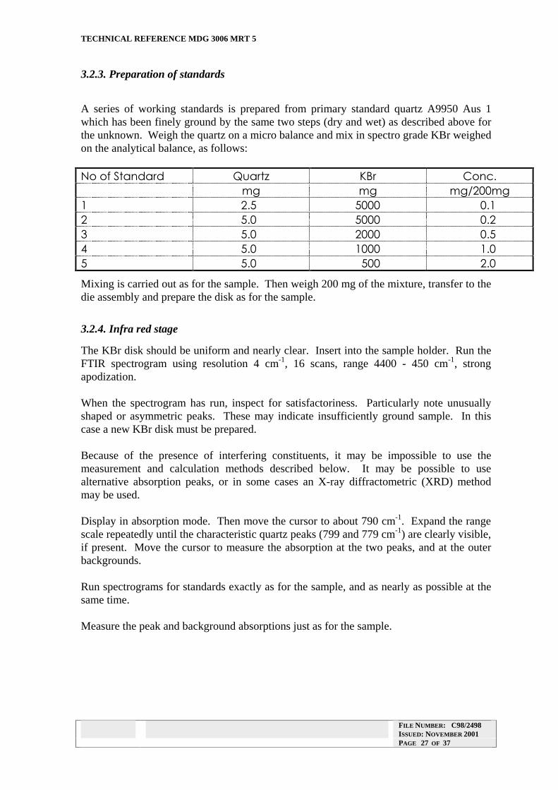
DOC NAME: BARGUID2.DOC ISSUE: A REVISION 2
TECHNICAL REFERENCE MDG 3006 MRT 5
3.2.3. Preparation of standards
A series of working standards is prepared from primary standard quartz A9950 Aus 1 which has been finely ground by the same two steps (dry and wet) as described above for the unknown. Weigh the quartz on a micro balance and mix in spectro grade KBr weighed on the analytical balance, as follows:
No o. ?tan9ar9 Quartz KBr Conc. mg mg mg/2oomg 1 2.5 5ooo o.1 2 5.o 5ooo o.2 � 5.o 2ooo o.5 4 5.o 1ooo 1.o 5 5.o 5oo 2.o
Mixing is carried out as for the sample. Then weigh 200 mg of the mixture, transfer to the die assembly and prepare the disk as for the sample.
3.2.4. Infra red stage
The KBr disk should be uniform and nearly clear. Insert into the sample holder. Run the FTIR spectrogram using resolution 4 cm-1, 16 scans, range 4400 - 450 cm-1, strong apodization.
When the spectrogram has run, inspect for satisfactoriness. Particularly note unusually shaped or asymmetric peaks. These may indicate insufficiently ground sample. In this case a new KBr disk must be prepared.
Because of the presence of interfering constituents, it may be impossible to use the measurement and calculation methods described below. It may be possible to use alternative absorption peaks, or in some cases an X-ray diffractometric (XRD) method may be used.
Display in absorption mode. Then move the cursor to about 790 cm-1. Expand the range scale repeatedly until the characteristic quartz peaks (799 and 779 cm-1) are clearly visible, if present. Move the cursor to measure the absorption at the two peaks, and at the outer backgrounds.
Run spectrograms for standards exactly as for the sample, and as nearly as possible at the same time.
Measure the peak and background absorptions just as for the sample.
FILE NUMBER: C98/2498 ISSUED: NOVEMBER 2001 PAGE 27 OF 37

DOC NAME: BARGUID2.DOC ISSUE: A REVISION 2
TECHNICAL REFERENCE MDG 3006 MRT 5
3.3. Calculations
For each peak reading (at 799 and 779 cm-1), for each standard and sample, calculate by interpolation the equivalent background reading, and subtract this from the peak reading as follows.
Equivalent background reading at x cm-1
N L − xA = (A − A )B L R N − NL R
Net peak reading at x cm-1
′ Ax A Ax B = − where:
Ax’= net absorption measured at x cm-1
AL = background absorption measured at left of peaks AR = background absorption measured at right of peaks Ax = absorption measured at x cm-1
NL = cm-1 of background absorption measured at left of peaks NR = cm-1 of background absorption measured at right of peaks x = cm-1 of peak (799 or 779)
For the working standards, for each wavenumber, plot net absorption as ordinate against milligrams of quartz in the standard, or carry out an equivalent least-squares regression.
If reasonably linear plots are obtained, these may be used as the calibration graphs.
The number of milligrams of quartz in an unknown sample is determined from Ax’, the net peak absorption at each wavenumber by reading off the appropriate calibration graph. These should agree within ±5%. Take the mean.
Concentration of quartz in the insoluble residue (percent) m + m
G = 100 MSK R
m mR P
where: G = concentration of quartz in the insoluble residue, expressed as percentage Ms = mean milligrams of quartz obtained from the calibration graphs mR = mass of sample of insoluble residue mixed with KBr to make the disk,
expressed in milligrams mK = mass of KBr used to mix with the sample, expressed in milligrams mP = mass of finished disk, expressed in milligrams
Concentration of quartz in the original sample of stonedust (percent) GE
H = 100
where: H = concentration of quartz in the original sample of stonedust, expressed in percent G = concentration of quartz in the insoluble residue, expressed in percent, as calculated above E = concentration of insoluble residue in the original sample, expressed in percent, as calculated in Section 3.2.1.
FILE NUMBER: C98/2498 ISSUED: NOVEMBER 2001 PAGE 28 OF 37
DOC NAME: BARGUID2.DOC ISSUE: A REVISION 2
TECHNICAL REFERENCE MDG 3006 MRT 5
PART C: TEST METHODS FOR COAL MINE ROADWAY DUST
INTRODUCTION
1.1 Purpose and Scope
Every coal mine is required to carry out a program of application of stonedust, to control the explosibility of the deposited dust on the roof, ribs and floor.
It is essential that each mine institute regular sampling and analysis of roadway dust, to ensure that the explosibility of the dust is being controlled to a level where dust explosions will not occur.
The sampling program may be carried out wholly or partly by the Department’s Roadway Dust Examiners.
The purpose of Part C is to provide a number of methods whereby the incombustible content of the collected samples may be determined. This is a measure of the inertness of the dust. The incombustible content is then compared with the standard provided by the relevant clause of the regulation.
Information on the frequency and location of sampling, and on the process of carrying out sampling is included in the regulation.
Part C includes four different methods of analysis for incombustible content. Any of them may be used, but in cases of dispute, the Chemical Method for Roadway Dust is the “specified method”, and determinations by this method will be regarded as authoritative.
This Part should be considered as a benchmark of “Good Industry Practice” on the matter of analysis of roadway dust. It is intended that it be read as auxiliary to setting up a system of explosion suppression in each mine which will reduce the risks of explosion and fire in the mine to the minimum feasible level using the knowledge and techniques available to the industry.
1.2 Relationship with Regulations
The Coal Mines (Underground) Regulation, 1999, requires that a program of roadway dust sampling and analysis be instituted in each mine and specifies minimum requirements for such a program.
In connection with the collection and analysis of samples of roadway dust, the Regulation provides that regard is to be had to guidance material issued by the Chief Inspector. For roadway dust analysis, this publication is the guidance material referred to.
The Regulation also provides that the Chief Inspector may, by notice in the Gazette, specify a method for determination of incombustible content of samples of roadway dust. As part of the process of implementing the Regulation, the Chief Inspector will issue a notice to the effect that the Chemical Method for Roadway Dust included in this publication is the “specified method”.
FILE NUMBER: C98/2498 ISSUED: NOVEMBER 2001 PAGE 29 OF 37
DOC NAME: BARGUID2.DOC ISSUE: A REVISION 2
TECHNICAL REFERENCE MDG 3006 MRT 5
ANALYSIS METHOD 1 - CHEMICAL METHOD FOR ROADWAY DUST
Equipment required
(1) An analytical balance with a sensitivity of 0.1 milligram or better.
(2) A 250 micrometre aperture size sieve. The sieve must comply with Australian Standard 1152-1973 and should be equipped with lid and receiver.
(3) A hot air oven regulated to maintain a temperature of 105°C ± 2°C.
(4) A furnace equipped with a temperature controller which will maintain its temperature at 515°C ± 15°C.
(5) Dishes made of silica or other suitable material.
(6) Desiccator.
Method
(1) Air dry the sample if necessary to allow it to be sieved successfully. A correction may be made for moisture lost. If it is desired to make this correction, weigh the dust before drying, and designate this weight as A. Weigh after drying, and designate this weight as B. Calculate the percentage loss M as:
A B−M = × 100
A
(2) Sieve the sample through the 250 micrometre sieve.
(3) Weigh about 1 gram of the material which passed through the 250 micrometre sieve to the nearest 0.1 milligram in an open dish and place in the air oven for one hour at 105°C. Designate the weight of material taken as W.
(4) Cool the sample in a desiccator and reweigh. The loss in weight is the moisture in the sample. Designate this loss in weight as D.
(5) Place the sample in the furnace at 500-530°C for two hours to burn off combustible material.
NOTE: A sample of limestone dust should be processed with each batch of samples. The limestone should be weighed before and after ignition. This is to check that the temperature of the furnace does not exceed the decomposition temperature of the limestone.
(6) Cool the residue in a desiccator and weigh it. Designate the weight of residue as R.
FILE NUMBER: C98/2498 ISSUED: NOVEMBER 2001 PAGE 30 OF 37
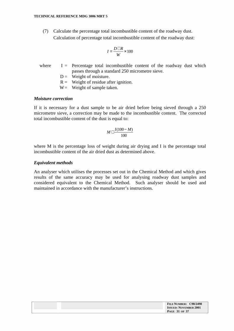
DOC NAME: BARGUID2.DOC ISSUE: A REVISION 2
TECHNICAL REFERENCE MDG 3006 MRT 5
(7) Calculate the percentage total incombustible content of the roadway dust.
Calculation of percentage total incombustible content of the roadway dust:
D R+I = ×100
W
where I = Percentage total incombustible content of the roadway dust which passes through a standard 250 micrometre sieve.
D = Weight of moisture. R = Weight of residue after ignition. W= Weight of sample taken.
Moisture correction
If it is necessary for a dust sample to be air dried before being sieved through a 250 micrometre sieve, a correction may be made to the incombustible content. The corrected total incombustible content of the dust is equal to:
I(100 − M)M +
100
where M is the percentage loss of weight during air drying and I is the percentage total incombustible content of the air dried dust as determined above.
Equivalent methods
An analyser which utilises the processes set out in the Chemical Method and which gives results of the same accuracy may be used for analysing roadway dust samples and considered equivalent to the Chemical Method. Such analyser should be used and maintained in accordance with the manufacturer’s instructions.
FILE NUMBER: C98/2498 ISSUED: NOVEMBER 2001 PAGE 31 OF 37

DOC NAME: BARGUID2.DOC ISSUE: A REVISION 2
TECHNICAL REFERENCE MDG 3006 MRT 5
ANALYSIS METHOD 2 - VOLUMETRIC METHOD FOR ROADWAY DUST
Equipment and reagent required
(1) Top loading balance with sensitivity of 0.05 grams or better.
(2) Fifty millilitre Redwood Viscometer flasks (Kohlrausch) or similar.
(3) Plastic funnel to fit neck of flasks.
(4) Fifty millilitre burette with 0. 1 millilitre subdivisions.
(5) Industrial methylated spirits.
(6) A 250 micrometre aperture size sieve equipped with a lid and receiver.
Equipment should comply with relevant Australian Standards, British Standards or equivalents where applicable.
Method
(1) Air dry the sample if necessary to allow it to be sieved successfully. A correction may be made for moisture lost. If it is desired to make this correction, weigh the dust before drying, and designate this weight as A. Weigh after drying, and designate this weight as B. Calculate the percentage loss M as:
A B−M = × 100
A
(2) Weigh out 20.0 ± 0.05 grams of roadway dust which passes through a 250 micrometre test sieve.
(3) Introduce sample into a dry volumetric flask using a plastic funnel.
(4) Add about 15 millilitres of methylated spirits to the flask from the burette. Swirl the contents around and ensure that the sample is thoroughly wet.
(5) Add methylated spirits from the burette until the level reaches the 50 millilitre calibrated mark of the flask.
(6) Read and record the volume of methylated spirits used from the burette to the nearest 0.1 ml (reading the bottom of the meniscus).
(7) The percentage incombustibles content for the sample is then read from a graph or table prepared as detailed below and recorded.
NOTE: The methylated spirits may be re-used, provided all suspended matter is effectively removed.
Preparation of the graph
(1) Obtain twenty samples of roadway dust which pass through a 250 micrometre standard test sieve and which:
(a) Have solid incombustible contents which cover the range 65 per cent to 90 per cent.
(b) Contain no more than 2 per cent by weight of moisture.
FILE NUMBER: C98/2498 ISSUED: NOVEMBER 2001 PAGE 32 OF 37

DOC NAME: BARGUID2.DOC ISSUE: A REVISION 2
TECHNICAL REFERENCE MDG 3006 MRT 5
(2) For each sample determine the percentage solid incombustibles content by the Chemical Method for Roadway Dusts.
(3) For each sample determine the volume of methylated spirits required to fill the volumetric flask.
(4) Plot the percentage solid incombustibles content versus the volume of methylated spirits required. The graph should be a straight line. A table may be prepared from this graph giving solid incombustible content at intervals of 0. 1 ml of methylated spirits.
NOTE: Care should be taken to ensure that the roadway dust samples used to prepare the graph do not contain calcium chloride.
Verification of results
(1) The incombustible content of at least one in every fifty determinations made by the volumeter method should be check tested by the Chemical Method for Roadway Dusts and a record kept of these results.
(2) The Chief Inspector should be notified in writing by the manager of the mine, if the volumeter incombustibles result is higher than the Chemical Method for Roadway Dusts result by more than 5 per cent absolute.
Moisture correction:
If it is necessary for a dust sample to be air dried before being sieved through a 250 micrometre sieve, a correction may be made to the incombustible content. The corrected total incombustible content of the dust is equal to:
I (100 − M )M +
100
where M is the percentage loss of weight during air drying and I is the percentage total incombustible content of the air dried dust as determined above.
FILE NUMBER: C98/2498 ISSUED: NOVEMBER 2001 PAGE 33 OF 37

DOC NAME: BARGUID2.DOC ISSUE: A REVISION 2
TECHNICAL REFERENCE MDG 3006 MRT 5
ANALYSIS METHOD 3 - COAL ASH INCOMBUSTIBLES ANALYSER METHOD FOR ROADWAY DUST
This method is for the determination of incombustible content of samples of roadway dust by means of the instrument known as Model 301, Coal Ash Incombustibles Analyser manufactured by Mineral Control Instrumentation of Unley, South Australia. It is referred to in this Method as “the instrument”.
Manner of Use
Limitation: The instrument is not to be used underground in any coal or shale mine.
Equipment required
(1) The instrument, together with sample holders.
(2) A 250 micrometre aperture size sieve. The sieve must comply with Australian Standard 1152-1973 and should be equipped with lid and receiver.
Method
(1) Air dry the sample if necessary to allow it to be sieved successfully. A correction may be made for moisture lost. If it is desired to make this correction, weigh the dust before drying, and designate this weight as A. Weigh after drying, and designate this weight as B. Calculate the percentage loss M as:
A B−M = × 100
A
(2) Calibrate the instrument using the two internal standards.
(3) Place a sufficient quantity of the roadway dust which passed through the 250 micrometre sieve in the sample holder to give a layer at least 20 mm thick.
(4) Gently tap the sample holder a few times to consolidate the dust.
(5) Place the sample holder in position on the instrument.
(6) Take two readings of the incombustible content of the sample on the instrument and report both and the average of these.
(7) Check the setting of the instrument by reading one or both of the internal standards as if they were samples
(8) At least once a year check the operation of the instrument with a standard sample which has been analysed by the Chemical Method.
FILE NUMBER: C98/2498 ISSUED: NOVEMBER 2001 PAGE 34 OF 37

DOC NAME: BARGUID2.DOC ISSUE: A REVISION 2
TECHNICAL REFERENCE MDG 3006 MRT 5
Moisture correction
If it is necessary for a dust sample to be air dried before being sieved through a 250 micrometre sieve, a correction may be made to the incombustible content. The corrected total incombustible content of the dust is equal to:
I (100 − M )M +
100
where M is the percentage loss of weight during air drying and I is the percentage total incombustible content of the air dried dust as determined by the gamma ray instrument.
FILE NUMBER: C98/2498 ISSUED: NOVEMBER 2001 PAGE 35 OF 37

DOC NAME: BARGUID2.DOC ISSUE: A REVISION 2
TECHNICAL REFERENCE MDG 3006 MRT 5
ANALYSIS METHOD 4 - COLORIMETRIC METHOD FOR ROADWAY DUST
Equipment required
(1) Sieve of nominal aperture 250 micrometres, complying with Australian Standard 1152-1973 (or amendment thereto).
(2) A supply of clean white paper.
(3) A spatula (capable of dispensing as much dust as can be heaped on a five cent coin).
(4) Standard colour sample, prepared as detailed below.
Method
(1) Air dry the sample if necessary. Sieve the sample through the 250 micrometre sieve and mix the sieved sample thoroughly but do not grind it.
(2) Compare the colour of the mixed sieved sample with that of the standard colour sample. The comparison must be made under conditions of good and even illumination.
(3) If there is an obvious colour difference between the sample dust and the standard colour sample, record that the sample dust is or is not, lighter in colour than the standard colour sample, as the case may be.
(4) If there is no obvious difference in colour, take a small portion of the sample dust and of the standard colour sample by spatula and place them side by side on clean white paper. Press the portions of dust flat with the spatula to form a smooth surface.
(5) Examine the portions of dust and record that the sample is or is not, lighter in colour than the standard colour sample or is indistinguishable from it, as the case may be.
Preparation of standard colour sample
(1) Grind some dry coal dust or small dry coal from the seam for which the standard colour sample is being prepared so that it passes through the 250 micrometre sieve.
(2) Determine the ash content of the sieved coal dust according to Australian Standard 1038, Part 3-1979. The ash content should not exceed 20 per cent by weight on a dry basis. (This is to avoid the use of shale in the preparation of a standard colour sample.)
(3) Sieve through the 250 micrometre sieve some dry stonedust of the type most widely used in the mine.
(4) The standard colour sample must have a solid incombustible content equal to or greater than the total incombustible content required in a particular sample.
(5) Weigh quantities of the sieved coal dust and sieved stonedust in proportions which will give the desired solid incombustible content.
(6) Mix the dusts thoroughly by stirring, shaking or rolling the mixture but do not grind the mixture.
FILE NUMBER: C98/2498 ISSUED: NOVEMBER 2001 PAGE 36 OF 37

DOC NAME: BARGUID2.DOC ISSUE: A REVISION 2
TECHNICAL REFERENCE MDG 3006 MRT 5
(7) Using the Chemical Method for Roadway Dusts, determine the solid incombustible content of the mixture and verify that it is not less than the required value.
(8) At intervals of not more than 12 months, re-test the standard as required in (7) above and keep a record of the results of these tests; if the standard has a solid incombustible content which is less than that required in (4) above, replace the standard with a new one.
FILE NUMBER: C98/2498 ISSUED: NOVEMBER 2001 PAGE 37 OF 37