guideline for electrical contractors - cape...
TRANSCRIPT

ELECTRICITY SERVICES DEPARTMENT
GUIDELINE FOR ELECTRICAL
CONTRACTORS
1ST EDITION
(Revision 0, 2014-06-24)

2 | P a g e
CONTENTS
ABBREVIATIONS .................................................................................................................... 4
1 SCOPE ............................................................................................................................ 4
2 REGULATORY CONTEXT ................................................................................................. 4
3 INTERPRETATION ............................................................................................................. 5
4 INDEMNITY ..................................................................................................................... 5
5 COPYRIGHT .................................................................................................................... 5
6 ELECTRICAL CONTRACTORS .......................................................................................... 5
7 FORMS AND INSPECTIONS ............................................................................................. 6
8 NOMINAL SUPPLY VOLTAGE .......................................................................................... 6
9 NEW SERVICE CONNECTIONS AND UPGRADES ........................................................... 6
9.1 General ....................................................................................................................... 6
9.2 Group Schemes ......................................................................................................... 8
10 RETROFITS ....................................................................................................................... 9
10.1 Retrofit Scenarios ....................................................................................................... 9
10.2 General ..................................................................................................................... 12
10.3 Single Residential and Single Commercial .......................................................... 12
10.4 Group Schemes ....................................................................................................... 13
11 ADDITIONAL RESIDENTIAL METERING ON SAME ERF .................................................. 14
11.1 General ..................................................................................................................... 14
11.2 Single Dwelling Units with Second Dwelling ......................................................... 14
11.3 Overhead Service Connections ........................................................................... 15
11.4 Mid-block Overhead Service Connections ......................................................... 15
11.5 Three or More Prepayment Meters on Same Property ...................................... 16
12 BUILDER’S SUPPLY/TEMPORARY CONNECTION........................................................... 16
12.1 Requirements ........................................................................................................... 16
12.2 Serviced Residential Erf .......................................................................................... 16
12.3 Temporary Three-phase Supply............................................................................. 16
13 CHANGES FROM OVERHEAD TO UNDERGROUND ..................................................... 16
14 EARTHING REQUIREMENTS ........................................................................................... 17
14.1 Single Residential Units ............................................................................................ 17
14.2 Industrial, Commercial and Sectional Title Complexes ..................................... 17
14.3 Supplies Larger Than 150 A .................................................................................... 17
15 LOAD CONTROL DEVICES ............................................................................................ 18

3 | P a g e
16 METER ROOM REQUIREMENTS ..................................................................................... 18
16.1 Location .................................................................................................................... 18
16.2 Access....................................................................................................................... 18
16.3 Construction ............................................................................................................. 19
16.4 Lighting ..................................................................................................................... 19
16.5 Services ..................................................................................................................... 20
16.6 Accommodation of Meters ................................................................................... 20
17 EMBEDDED GENERATION ............................................................................................. 20
17.1 Small-scale Embedded Generation ..................................................................... 20
17.2 Embedded Generation of 1 MVA or Larger ....................................................... 21
18 STANDBY SUPPLIES (GENERATORS AND UPS) .............................................................. 21
18.1 Application and Approval Requirements ........................................................... 21
18.2 Safety Requirements ............................................................................................... 21
18.3 Connection Requirements ..................................................................................... 22
Annex A: Retrofit Scenarios ............................................................................................... 23
Annex B: Meter Box Sizes .................................................................................................. 33
Annex C: Earthing Systems for Customer Connections .................................................. 35
Annex D: Installation Earthing Requirements ................................................................... 37
Annex E: Typical Earthing Arrangements for Supplies Exceeding 150 A ....................... 38
Annex F: Approved Meter Room Signage ....................................................................... 40
Annex G: Approved Warning Sign for Generator Installations ....................................... 41
Annex H: Connection of Standby Generator ................................................................... 42
Annex I: Customer Support Centres ................................................................................. 43
Annex J: ESD District Supply Areas ................................................................................... 46
Annex K: Inspector Contact Details ................................................................................. 58
ABBREVIATIONS
AMI Advanced Metering Infrastructure
CIU Customer Interface Unit (used in conjunction with MCU for split
metering)
CSS Customer Support Services
CT Current Transformer
ESD Electricity Services Department
MCU Meter Control Unit (used in conjunction with CIU for split metering)
NERSA The National Energy Regulator of South Africa
O/H Overhead
OHS Act Occupational Health and Safety Act, 1993
PCB Passive Common Base
PVC Polyvinyl Chloride
PPM Pre-payment Meter
SSEG Small-scale Embedded Generation
SWA Steel Wire Armoured
1 SCOPE
This guideline is intended to set out the basic requirements applicable to
electricity service connections and is applicable to all electrical contractors
working in the City of Cape Town Electricity Services Department area of
jurisdiction.
Where there is any discrepancy between this guideline and any Electricity
Services Department policy, the relevant policy will apply.
2 REGULATORY CONTEXT
The following documents contain provisions that, whether referenced in the
text or not, constitute requirements of these guidelines.
Legislation and Codes: SANS 10142-1: The Wiring of Premises Part 1: Low-
voltage installations, as amended
National Building Regulations and Building
Standards Act, Act 103 of 1977, as amended

5 | P a g e
National Building Regulations, GNR 2378 of 12
October 1990, as amended
Occupational Health and Safety Act, Act No. 85 of
1993, as amended
Electrical Installation Regulations, 2009 as
amended (Promulgated in terms of the
Occupational Health and Safety Act by GNR 242
of 6 March 2009)
City By-Laws: City of Cape Town Electricity Supply By-law, 2010
(promulgated under Provincial Notice No. 6727 on
16 April 2010), as amended
City Policies: Policy No. 11107: Installation of prepayment meters
(PPM)
National Guidelines: NRS 098: Guidelines for the Installation and Safe
Use of Portable Generators on Utilities’ Networks
City Guidelines: Guidelines for Embedded Generation (draft)
3 INTERPRETATION
Certain developments or activities may be subject to approval by Provincial
Government or National Government Departments in terms of national or
provincial legislation. This document must not be interpreted as granting any
such approvals.
4 INDEMNITY
This document does not create liability on the part of the City of Cape Town or
any officer thereto for any damages that may result from reliance thereon.
5 COPYRIGHT
All rights reserved by the City of Cape Town, South Africa. No part of this
document may be reproduced in any form without the written permission of
the City of Cape Town, with the exception of photocopying for educational
purposes.
6 ELECTRICAL CONTRACTORS
Electrical contractors must be registered by the Department of Labour in
compliance with Regulation 6(1) of the Electrical Installation Regulations.

6 | P a g e
Electrical contractors must produce the registration certificate issued by the
Department of Labour on request of an Installation Inspector, Law
Enforcement Officer or any other authorized ESD official.
7 FORMS AND INSPECTIONS
It is the responsibility of the applicant (or an electrical contractor on its behalf)
to obtain the following details before submitting any application form:
i) existing and desired supply size.
ii) existing meter type and position (if applicable).
An application for the supply of services must be submitted at the relevant
office (see Annex I) before any installation work is started and must be
completed in full (street address and erf number to be stated). The applicant
must complete all applicable details and the electrical contractor is to do the
same. The latest version of the application form is available from the website:
www.capetown.gov.za or the relevant office (see Annex H).
A Certificate of Compliance must be submitted at the relevant Electricity CSS
office before an installation, or any part of an installation that is to be metered
separately, may be commissioned. The contractor is to satisfy himself that the
installation is electrically safe.
When there is a request for a supply to be disconnected so that work can be
done on an installation, a Certificate of Compliance must be submitted by the
electrical contractor for the work that was done.
8 NOMINAL SUPPLY VOLTAGE
The voltage at which supply will be given will be determined by the ESD in
accordance with the Electricity Tariff Schedule and technical considerations,
and will be one of the following:
i) Low voltage, single phase: 230 V
ii) Low voltage, three phase: 400 V
iii) Medium voltage: 11,50 kV or 11,66 kV, depending on the area.
iv) High voltage: 66 kV or 132 kV, depending on the area.
9 NEW SERVICE CONNECTIONS AND UPGRADES
9.1 General
A minimum of 10 working days’ notice must be given to the ESD when ready
for the ESD cable to be connected, if the supply cable is at the boundary. If
there is no supply cable at the boundary, the supply will be connected within
30 days, where possible.
7 | P a g e
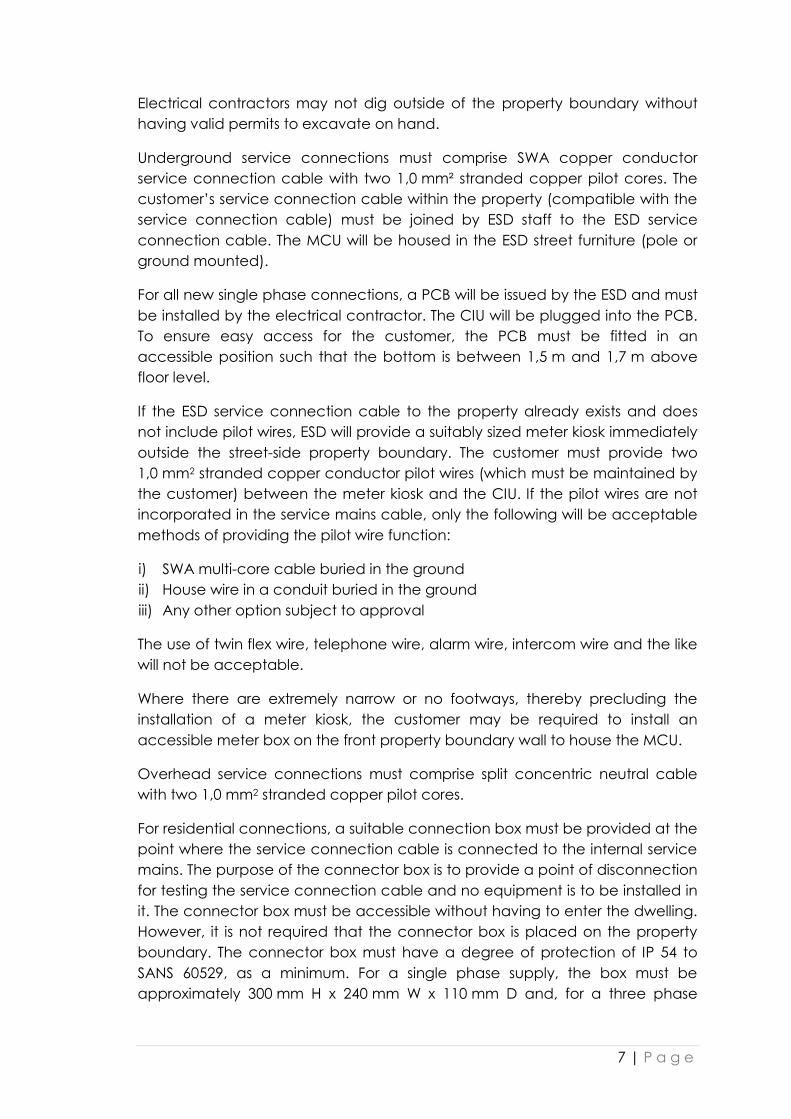
Electrical contractors may not dig outside of the property boundary without
having valid permits to excavate on hand.
Underground service connections must comprise SWA copper conductor
service connection cable with two 1,0 mm² stranded copper pilot cores. The
customer’s service connection cable within the property (compatible with the
service connection cable) must be joined by ESD staff to the ESD service
connection cable. The MCU will be housed in the ESD street furniture (pole or
ground mounted).
For all new single phase connections, a PCB will be issued by the ESD and must
be installed by the electrical contractor. The CIU will be plugged into the PCB.
To ensure easy access for the customer, the PCB must be fitted in an
accessible position such that the bottom is between 1,5 m and 1,7 m above
floor level.
If the ESD service connection cable to the property already exists and does
not include pilot wires, ESD will provide a suitably sized meter kiosk immediately
outside the street-side property boundary. The customer must provide two
1,0 mm2 stranded copper conductor pilot wires (which must be maintained by
the customer) between the meter kiosk and the CIU. If the pilot wires are not
incorporated in the service mains cable, only the following will be acceptable
methods of providing the pilot wire function:
i) SWA multi-core cable buried in the ground
ii) House wire in a conduit buried in the ground
iii) Any other option subject to approval
The use of twin flex wire, telephone wire, alarm wire, intercom wire and the like
will not be acceptable.
Where there are extremely narrow or no footways, thereby precluding the
installation of a meter kiosk, the customer may be required to install an
accessible meter box on the front property boundary wall to house the MCU.
Overhead service connections must comprise split concentric neutral cable
with two 1,0 mm2 stranded copper pilot cores.
For residential connections, a suitable connection box must be provided at the
point where the service connection cable is connected to the internal service
mains. The purpose of the connector box is to provide a point of disconnection
for testing the service connection cable and no equipment is to be installed in
it. The connector box must be accessible without having to enter the dwelling.
However, it is not required that the connector box is placed on the property
boundary. The connector box must have a degree of protection of IP 54 to
SANS 60529, as a minimum. For a single phase supply, the box must be
approximately 300 mm H x 240 mm W x 110 mm D and, for a three phase

8 | P a g e
supply, the connector box must be approximately 445 mm H x 460 mm W x
200 mm D.
The customer’s earth electrode must be installed on the customer’s property
and an earthing lead from the earth electrode must be terminated onto the
bar provided for neutral and earthing purposes, in a suitable box between the
point of supply and the point of control, in accordance with SANS 10142-1. The
connection box may be used for this purpose.
As defined by the OHS Act, the point of supply remains the point where the
service connection cable enters the property, irrespective of the position of
the meter.
9.2 Group Schemes
Group schemes are flats, cluster houses or commercial developments on a
single erf, where no single unit is larger than 100 A, 3 phase.
For new connections and any change to the supply connections to blocks of
flats and sectional title developments where the design of the complex is such
that it is technically feasible to cable from a single common meter room
(directly accessible at all times from a public street) to each unit in the
complex, the following will apply:
i) Pilot wire split MCUs (one for each unit) must be installed in the common
meter room.
ii) Pilot wires must be installed by an electrical contractor appointed by the
Body Corporate between each MCU in the common meter room and the
CIU in each dwelling unit. The Body Corporate is responsible for the integrity
of these pilot wires.
iii) A PCB, supplied by ESD, onto which the CIU is installed, must be fitted in
each dwelling unit by the Body Corporate’s electrical contractor in the line
of the supply conductors from the common meter room to the point of
control on the main distribution board of each unit.
iv) A bulk supply point will not be provided.
Bulk conventional metering systems are installed only where the complex is of
such a size that the above arrangement is not physically possible and
distributed metering points within the complex are required from a technical
point of view. In such large complexes the body corporate will have to sub-
meter the electricity supplied to each dwelling and be responsible for
collecting the revenue therefor.
Note: The ESD does not permit distributed meter rooms or kiosks housing ESD-
owned metering because of the risk that unmetered points can be created
which could be tapped into, knowingly or unknowingly, resulting in revenue
losses to the ESD. Also, the ESD cannot maintain and may not be able to
access this infrastructure on private property.

9 | P a g e
10 RETROFITS
10.1 Retrofit Scenarios
Eight retrofit scenarios have been identified as illustrated in Annex A and
described below.
Scenario Solution ESD Duties Contractor Duties
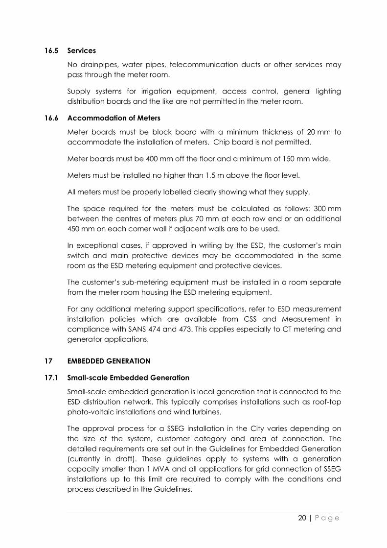
1. Supply from
mid-boundary
position where
there is no existing
street-front LV
reticulation.
(See Annex A,
figures A1, A2 and
A3)
A. Single phase:
MCU to be
housed in pole
box on mid-
boundary mains
pole.
B. Three phase:
Customer to
convert supply
to single phase.
Connection to
be treated as A.
(If customer
cannot convert
to single phase,
retrofit cannot
be done)
A. ESD to install
a pole box
on the pole
where the
supply is
being fed
from to
house the
meter.
B. Same as A.
A. Contractor to
install passive
common base
in the dwelling
and issue a
Certificate of
Compliance.
B. Same as A and
convert
installation to
single phase.
2. Supply from
mid-boundary
position where
there is existing
street-front LV
reticulation with
adequate spare
capacity.
(See Annex A,
figures A1, A2 and
A3)
A. Single phase:
Same as 1A.
B. Three phase:
Customer to
convert supply
to single phase.
Connection to
be treated as A.
C. Three phase: If
customer
cannot convert
to single phase,
supply to be fed
via underground
cable from
street-front LV
reticulation
A. Same as 1A.
B. Same as A.
C. Install
service
connection
for
customer.
Install MCU
in suitable
meter kiosk.
A. Same as 1A
B. Same as A and
convert
installation to
single phase.
C. Contractor to
install sub-
service mains
with pilot wires
to street-front
and issue
Certificate of
Compliance.
10 | P a g e
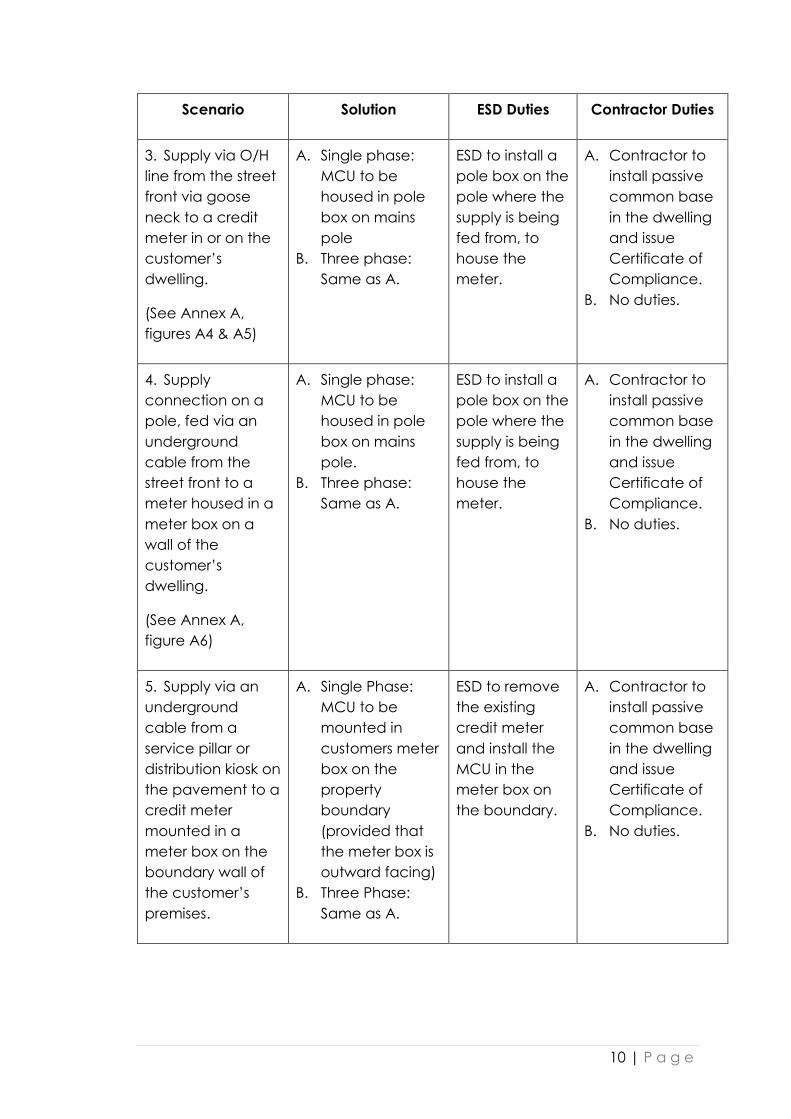
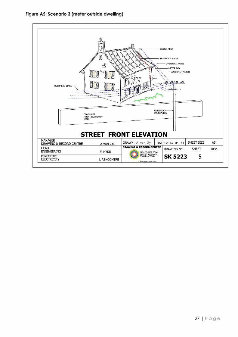
Scenario Solution ESD Duties Contractor Duties
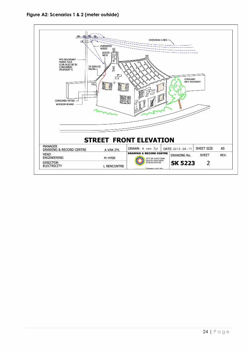
3. Supply via O/H
line from the street
front via goose
neck to a credit
meter in or on the
customer’s
dwelling.
(See Annex A,
figures A4 & A5)
A. Single phase:
MCU to be
housed in pole
box on mains
pole
B. Three phase:
Same as A.
ESD to install a
pole box on the
pole where the
supply is being
fed from, to
house the
meter.
A. Contractor to
install passive
common base
in the dwelling
and issue
Certificate of
Compliance.
B. No duties.
4. Supply
connection on a
pole, fed via an
underground
cable from the
street front to a
meter housed in a
meter box on a
wall of the
customer’s
dwelling.
(See Annex A,
figure A6)
A. Single phase:
MCU to be
housed in pole
box on mains
pole.
B. Three phase:
Same as A.
ESD to install a
pole box on the
pole where the
supply is being
fed from, to
house the
meter.
A. Contractor to
install passive
common base
in the dwelling
and issue
Certificate of
Compliance.
B. No duties.
5. Supply via an
underground
cable from a
service pillar or
distribution kiosk on
the pavement to a
credit meter
mounted in a
meter box on the
boundary wall of
the customer’s
premises.
A. Single Phase:
MCU to be
mounted in
customers meter
box on the
property
boundary
(provided that
the meter box is
outward facing)
B. Three Phase:
Same as A.
ESD to remove
the existing
credit meter
and install the
MCU in the
meter box on
the boundary.
A. Contractor to
install passive
common base
in the dwelling
and issue
Certificate of
Compliance.
B. No duties.

11 | P a g e
Scenario Solution ESD Duties Contractor Duties
6. Supply via an
underground
cable from a
service pillar or
distribution kiosk on
the pavement to a
credit meter
mounted in a
meter box on the
wall of the
customer’s
dwelling.
A. Single phase:
MCU to be
housed in meter
kiosk (in road
reserve).
B. Three phase:
MCU to be
housed in
customer’s
meter box on
property
boundary.
A. ESD to
replace
service pillar
or
distribution
kiosk with a
12-way
meter kiosk.
The MCU is
to be
housed in
the meter
kiosk.
B. ESD to install
MCU in
customer’s
new meter
box on
property
boundary.
A. Contractor to
install passive
common base
in the dwelling
and issue
Certificate of
Compliance.
B. Contractor to
install a meter
box (outward
facing, non-
metallic) on
customer’s
property
boundary.
7. Supply fed via
an underground
cable from a
meter kiosk on the
pavement to a
credit meter
mounted in a
meter box on the
boundary wall of
the customer’s
premises.
A. Single phase:
MCU to be
housed in the
meter kiosk.
B. Three phase:
MCU to be
mounted in the
customer’s
meter box on
the boundary
wall (only if
outward facing).
ESD to remove
credit meter
and install
MCU.
A. Contractor to
install passive
common base
in the dwelling
and issue
Certificate of
Compliance.
B. Contractor to
install a meter
box (outward
facing, non-
metallic) on
customer’s
property
boundary.

12 | P a g e
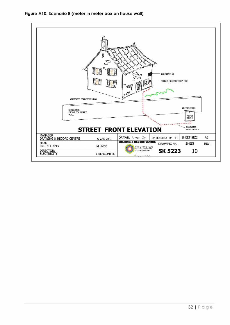
Scenario Solution ESD Duties Contractor Duties
8. Supply via an
underground
cable from a
credit meter in a
meter kiosk on the
pavement.
A. Single phase:
MCU to be
housed in the
meter kiosk.
B. Three phase:
MCU to be
housed in
customer’s
meter box on
property
boundary.
A. ESD to
remove
credit meter
and install
MCU in
meter kiosk.
B. ESD to install
MCU in
customer’s
new meter
box on
property
boundary.
A. Contractor to
install passive
common base
in the dwelling
and issue
Certificate of
Compliance.
B. Contractor to
install a meter
box (outward
facing, non-
metallic) on
customer’s
property
boundary.
Note: If a customer requests the removal of an existing conventional three
phase credit meter situated inside the premises, the
disconnection/reconnection fee must be paid. The ESD will remove the meter
and the electrical contractor appointed by the customer must conceal all
open wiring and submit a COC for all work done.
10.2 General
A PCB, issued by the ESD, must be installed by an electrical contractor
appointed by the customer (single phase connections only). The appropriate
CIU will be plugged into the PCB. To ensure easy access for the customer, the
PCB must be fitted in an accessible position such that the bottom is between
1,5 m and 1,7 m above floor level.
10.3 Single Residential and Single Commercial
The supply may be no larger than 100 A, 3 phase.
Only split PPMs may be used for retrofit cases whether to replace existing PPMs
or to replace conventional meters. The MCU must be installed in a street kiosk,
a pole-mounted box, meter room or box on the boundary of the property as
for new service connections.
Wireless split PPMs may be used where pilot wires do not exist or are not
operational ONLY if it is technically feasible. If wireless split PPMs are not
technically feasible and there is no history of tampering on the premises, an
integrated PPM may be used. Where there is a history of tampering, pilot wires

13 | P a g e
must be installed between the MCU and the CIU in the dwelling by the
customer’s electrical contractor at the consumer’s cost. The customer is
responsible for the integrity of these pilot wires beyond the point of supply.
For single phase connections, an electrical contractor must install a flush
mounted 100 mm x 100 mm draw box in the dwelling. A conduit must be
installed to the draw box for the supply cable and another conduit from the
draw box to the distribution board for the load conductors. The PCB to
accommodate the CIU must be secured over the draw box.
For three phase connections, the preference is to convert to single phase. If
this is not acceptable to the customer, a three phase split PPM must be
installed in accordance with the solution for the specific scenario.
(Cognizance should be given to the impact on load balancing when
converting to single phase).
10.4 Group Schemes
Group schemes are flats, cluster houses or commercial developments on a
single erf, where no single unit is larger than 100 A, 3 phase.
The installation of a PPM in an individual dwelling unit forming part of a bulk
metered block of flats or group scheme is not possible. The whole block or
group must be converted to individual PPM metering as part of one process.
Currently, due to technical considerations, only pilot wire PPMs are allowed in
blocks of flats, sectional title developments and full title developments
accessed via a private road. Recognising the cost implications, the two
options detailed below are allowed. In both cases, a single common meter
room accessible at all times from a public street must be provided by the Body
Corporate where the ESD will install the MCUs. If these options are not
acceptable or suitable, the retrofitting will have to be postponed until such
time that the PPM policy is reviewed as technology changes allow.
10.4.1 Option 1
If the design of the complex is such that it is technically feasible to cable from
the common meter room directly to each dwelling unit in the complex, the
Body Corporate’s electrical contractor must install a CIU in each dwelling unit
and install pilot wires between the MCUs and the CIUs.
The MCUs will be installed in the common meter room by the ESD.
The Body Corporate’s electrical contractor must install a PCB, onto which the
CIU will be fitted, in each dwelling unit in the line of the supply conductors from
the common meter room to the point of control on the main distribution board
of the dwelling unit. The PCBs are supplied by the ED and the cost is included in
the meter cost. The Body Corporate will be responsible for the maintenance of
the pilot wires to ensure communication between MCU and CIU.

14 | P a g e
10.4.2 Option 2
The Body Corporate provides one or more common locations (not in the single
common meter room) where the CIUs for all the dwellings units must be
accommodated. The Body Corporate’s electrical contractor must reroute the
supply and load conductors from the common meter room to the common
CIU location(s). Pilot wires must be installed from each MCU in the common
meter room to the corresponding CIU in the common CIU location(s). Each CIU
must be housed in a lockable enclosure for which the customer will be
responsible. The MCUs will be installed in the meter room by the ESD.
Note: For this option, the Body Corporate must consider the risks to the
customer and the premises and take full responsibility for all matters thereto
such as compliance with the Consumer Protection Act (Act 68 of 2008) and
the Protection of Information Act (Act 84 of 1982), the security of CIU
infrastructure, keypad mounting height, and note that, if a CIU is not installed in
the dwelling unit, the objective of active consumption monitoring by the
customer will not be met.
11 ADDITIONAL RESIDENTIAL METERING ON SAME ERF
11.1 General
Additional metering on properties zoned for residential use will be considered
only for residential purposes, i.e. for a second dwelling, and not for a business
or other activity run from the property.
Non-residential activities on a residential erf that require separate metering will
have to be privately sub-metered by the owner.
11.2 Single Dwelling Units with Second Dwelling
The authorised capacity of the property may remain the same, if so desired. In
the case of a 60 A connection, should the customer wish to increase the
supply capacity but retain the existing 16 mm² copper connection cable, the
supply will be limited to 80 A and the increase will be subject to payment of
the Development Capital tariff for the upgrade from 60 A to 80 A.
A meter box of approved size and type must be installed on the front property
boundary to accommodate a main circuit breaker, two circuit breakers to
supply the main dwelling and the second dwelling respectively, and two
MCUs. All circuit breakers in the meter box, as well as the main circuit breakers
in the distribution boards, must be Curve 2 (faster curve, white toggle), with a
fault rating of 5 kA. The current rating of the two secondary circuit breakers in
the meter box must be smaller than the rating of the main circuit breaker but
need not add up to exactly the rating of the latter. The electrical contractor
must supply and install all the circuit breakers to be used in the meter box.

15 | P a g e
The meter box may be installed in an existing boundary wall or a wall section
built for the purpose. Alternatively, if there is no wall, an approved free-
standing ground- mounted meter box may be used.
Split PPMs will be installed for both the main dwelling and the second dwelling.
If there is an existing credit meter or an integrated prepayment meter in the
main dwelling, this will be replaced with a split prepayment meter at the
customer’s cost. (See requirements for Retrofits).
If the service connection cable to the main dwelling has to be replaced, two
PVC insulated 1,0 mm² copper stranded pilot wires must be installed with the
connection cable between the meter box on the property boundary and the
main dwelling distribution board.
In the case of the second dwelling, a suitably sized service connection cable
with two PVC insulated 1,0 mm² copper stranded pilot wires must be installed
between the erf boundary meter box and the second dwelling distribution
board.
Pilot wires must comply with the requirements stated under New Service
Connections.
11.3 Overhead Service Connections
If a second prepayment meter is requested where there is an existing street-
front overhead supply dedicated to the property, the overhead connection
must be replaced with an underground cable from the street-front boundary.
A suitable meter box on the street-front boundary must be provided by the
customer. Circuit breaker, service connection cable and pilot wire
requirements are the same as for Single Dwelling Units with Second Dwelling.
The cost of undergrounding the connection will be added to the connection
fee for the additional metering.
11.4 Mid-block Overhead Service Connections
If an additional prepayment meter is requested where there is an existing mid-
block overhead connection to the main dwelling, the overhead connection
must be replaced with an underground cable from the street-front boundary.
A suitable meter box on the street-front boundary must be provided by the
customer. Where it is necessary to supply the connection from the mid-block
mains, the cost of bringing the overhead mid-block service connection point
to the street-front boundary must be borne by the property owner. Circuit
breaker, service connection cable and pilot wire requirements are the same
as for Single Dwelling Units with Second Dwelling.
16 | P a g e
11.5 Three or More Prepayment Meters on Same Property
The installation of three or more meters will be considered only on presentation
of building plans (showing more than two dwellings) approved by the City's
Planning & Building Development Management Department. The installation
will be subject to Policy No. 11107: Installation of prepayment meters.
12 BUILDER’S SUPPLY/TEMPORARY CONNECTION
12.1 Requirements
A separate compartment/enclosure must be made available for City
metering. This compartment/enclosure must house only the metering and
earthing requirements, and may not be used to house any of the electrical
contractor’s equipment.
All enclosures are to meet the requirements of SANS 10142-1 for temporary
builder’s supplies.
Temporary builder’s supplies are valid for a period of one year only. When this
time has expired, a new application must be made.
12.2 Serviced Residential Erf
The temporary supply to the property must be treated as the permanent
supply at all times. The electrical contractor’s main switch in the
compartment/enclosure must be an earth leakage unit with overload
protection.
12.3 Temporary Three-phase Supply
All temporary three phase connections are quotable.
For supplies of 100 A and less, the electrical contractor’s main switch in the
compartment/enclosure must be an earth leakage unit. For supplies
exceeding 100 A, an isolator of an approved type, equal to the requested
current rating, may be used provided that it is supplied via a CT-type earth
leakage unit with a sensitivity rating of no less than 125 mA.
13 CHANGES FROM OVERHEAD TO UNDERGROUND
The ESD will supply all cables and electrical material on its distribution system as
well as civil work outside the property at the customer’s expense. No civil work
on private property or changes to the building or customer’s installation will be
done by ESD. The relevant district must be contacted to co-ordinate
changeovers.
Split PPMs will be moved off the property and installed in a kiosk or in a pole-
mounted box. If the split PPM cannot be installed in a kiosk or in a pole-
mounted box, a connection box must be made available by the customer on

17 | P a g e
the property boundary. This connection box will be required for three phase
supplies especially.
For mid-block overhead connections, all supplies must be rerouted to the
street-front boundary via a connection or meter box that is to be fitted on the
boundary, where practicable.
All commercial installations will be quotable, irrespective of size of installation.
14 EARTHING REQUIREMENTS
14.1 Single Residential Units
An earthing system complying with SANS 10142-1 must be installed on the
customer’s property. The earth resistance must be 20 ohms or less.
A line tap used as connector for the neutral earthing is not acceptable. The
neutral and earth conductors must be terminated on a bar dedicated for
neutral/earthing.
The earth wire (earthing lead) between the earth electrode and the
connection box must be a minimum of 6 mm² PVC insulated copper
conductor.
14.2 Industrial, Commercial and Sectional Title Complexes
If there is only one building, an earth electrode must be installed in
accordance with Annex C. Where there are a number of factories, shops,
offices or flats on the same property, either a common earth electrode or
individual earth electrodes may be installed. Each earthing conductor from
the units and from the customer earth electrode must be terminated
separately from each other to a common, accessible, earth bar that must be
linked to a neutral bar.
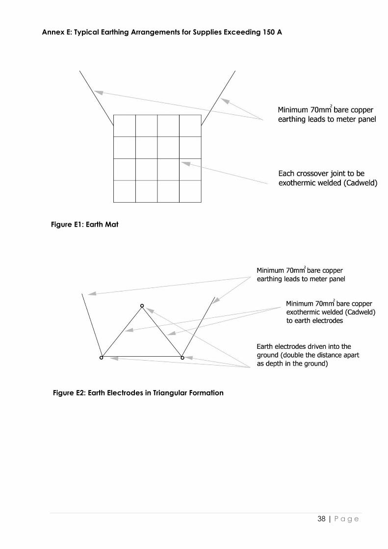
14.3 Supplies Larger Than 150 A
For supplies larger than 150 A, earth electrodes must be driven into the ground
in a minimum of three positions. The electrodes must be spaced at a distance
apart double their depth in the ground. The earth electrodes must be linked by
means of 70 mm² bare copper earthing conductors. Two 70 mm² bare copper
earthing wires are to run from two earth electrodes to the metering panel.
These two earthing wires must not touch anywhere in the trench where they
are laid and must not touch the distribution board as they enter.
Only brazed or exothermically welded (cad-weld or similar) joints may be used
to connect earthing conductors and trench earths to the electrode(s).
If earth electrodes cannot be driven into the ground, a 70 mm² copper mat,
trench or foundation earthing may be used.

18 | P a g e
15 LOAD CONTROL DEVICES
A 50 mm x 100 mm or a 50 mm diameter flush PVC box must be installed in the
wall, approximately 150 mm away from each distribution board. The supply
conductors (both live and neutral) for the geyser are to run via the PVC box to
the isolator at the geyser (if one is required to be fitted). A length of wire of
approximately 200 mm must be coiled in the PVC box and a blank cover must
be fitted.
Where a load control device is present, under no circumstances may seals on
the equipment terminal covers be removed nor may any alteration, temporary
or otherwise, be carried out on the geyser wiring in the distribution board
without the prior approval of the ESD. Any problems that may be encountered
regarding the output supply from any such device must be reported
immediately to the ESD fault reporting centre (Telephone 0860 103 089 or SMS
31220), whether after normal working hours or not. For safety purposes, note
that the relays may at any time be remotely switched on or off by the ESD.
If more than one geyser is being supplied from the same distribution board, the
following requirements must be met:
i) Both geyser circuits must be wired through the same PVC box.
ii) An additional 5 A circuit breaker must be installed in the distribution board
to supply the load control device.
iii) A separate contactor must be provided for each geyser controlled from
the load control device.
Note: If ESD has switched load control devices off, there will be a minimum
delay of approximately 15 minutes before the geyser can be switched on
again.
16 METER ROOM REQUIREMENTS
16.1 Location
Meter rooms must be located on the property boundary. The meter room must
be accessible directly from a public road reserve. The customer is responsible
for maintaining all cables on the property.
The meter room must be large enough to accommodate all equipment but
not less than 2, 2 m high and 1, 5 m wide or 1, 5 m long.
There must be a minimum of 1,0 m space immediately in front of all metering
equipment.
16.2 Access
24 hour access must be ensured.
19 | P a g e
Access by an unauthorized person is not to be permitted, unless an
arrangement has been made with an official from the ESD.
Under no circumstances may keys be given to any electrical contractor for the
purposes of accessing a meter room.
Under no circumstances may the meter room be used for the storage of any
items or equipment, such as cleaning equipment and the like.
16.3 Construction
The construction must be vermin proofed and all cable entries must be filled.
Walls on which meters are to be mounted must be at least 215 mm thick.
Unplastered walls must be constructed straight and plumb with a true face to
the interior.
A ceiling must be installed.
The walls and ceiling must be painted with white or cream PVA.
Adequate cross ventilation must be provided by two air bricks either at ceiling
or at floor level.
The floor must be level with the surrounding floor or must be more than 75 mm
above the surrounding ground level. Where this is not possible, steps must be
provided if the floor is more than 200 mm above or below the surrounding
floor/ground level.
The floor must be levelled such that any water entering the room will drain
towards the door and will not accumulate in the room.
The door must be substantial, open outward and be constrained from opening
more than 90°. No louvres may be fitted as part of the construction of the
door.
The door must be fitted with a pull handle and a suitable approved locking
device.
The door must be ventilated at the top if no air bricks have been fitted.
All applicable signage (minimum height to be 150 mm) must be fitted on the
meter room door (see Annex F).
16.4 Lighting
Suitable lighting must be provided to enable meters to be read easily.
The lighting circuit must be connected to the customer’s general lighting
distribution board and the light switch must be situated adjacent to the door.
20 | P a g e
16.5 Services
No drainpipes, water pipes, telecommunication ducts or other services may
pass through the meter room.
Supply systems for irrigation equipment, access control, general lighting
distribution boards and the like are not permitted in the meter room.
16.6 Accommodation of Meters
Meter boards must be block board with a minimum thickness of 20 mm to
accommodate the installation of meters. Chip board is not permitted.
Meter boards must be 400 mm off the floor and a minimum of 150 mm wide.
Meters must be installed no higher than 1,5 m above the floor level.
All meters must be properly labelled clearly showing what they supply.
The space required for the meters must be calculated as follows: 300 mm
between the centres of meters plus 70 mm at each row end or an additional
450 mm on each corner wall if adjacent walls are to be used.
In exceptional cases, if approved in writing by the ESD, the customer’s main
switch and main protective devices may be accommodated in the same
room as the ESD metering equipment and protective devices.
The customer’s sub-metering equipment must be installed in a room separate
from the meter room housing the ESD metering equipment.
For any additional metering support specifications, refer to ESD measurement
installation policies which are available from CSS and Measurement in
compliance with SANS 474 and 473. This applies especially to CT metering and
generator applications.
17 EMBEDDED GENERATION
17.1 Small-scale Embedded Generation
Small-scale embedded generation is local generation that is connected to the
ESD distribution network. This typically comprises installations such as roof-top
photo-voltaic installations and wind turbines.
The approval process for a SSEG installation in the City varies depending on
the size of the system, customer category and area of connection. The
detailed requirements are set out in the Guidelines for Embedded Generation
(currently in draft). These guidelines apply to systems with a generation
capacity smaller than 1 MVA and all applications for grid connection of SSEG
installations up to this limit are required to comply with the conditions and
process described in the Guidelines.

21 | P a g e
17.2 Embedded Generation of 1 MVA or Larger
Applications for the connection of embedded generation installation with a
capacity of 1 MVA or larger will be dealt with on a case-by-case basis. Before
submitting an application for connection, customers must have obtained a
generating licence from NERSA, failing which the application will not be
considered.
18 STANDBY SUPPLIES (GENERATORS AND UPS)
18.1 Application and Approval Requirements
Before any work may commence for either a new or an existing connection,
an application must be submitted to the relevant ESD Engineer for approval.
(The latest version of the application forms is available on the City’s website:
www.capetown/en/electricity.gov.za or from one of the CSS area office.) The
application must include a control circuit diagram of the generating unit,
including all interlocks with the electricity supply network. The application must
meet all legal requirements (e.g. approval from body corporate etc.)
Approval from the City’s Planning and Building Development Management
Department and Health Directorate with regard to zoning and noise and air
pollution services must be obtained so that the application form can be
completed prior to submitting it to the ESD.
Work may commence only upon written approval from the relevant ESD
Engineer.
18.2 Safety Requirements
The installation must comply with the following:
i) There must be no feedback onto the electricity supply network while the
generator unit is in operation.
ii) The must be no danger whatsoever to the user if the supply is changed
over manually to energise the generator unit during a power failure.
iii) Devices required to start and stop machinery must be in a position that can
be readily and conveniently reached by the person who operates the
machinery.
iv) Means must be provided to isolate the generator unit easily and safely in
case of an emergency or so that maintenance can be carried out.
v) The generator unit is not in an enclosed space that is not well ventilated.
vi) Nobody in the area surrounding the generator will be exposed to excessive
carbon monoxide from the engine exhaust.
vii) Generator noise and pollution must comply with legislation.
viii) The owner/tenant must comply with legislation for the storage of fuel.
ix) An easily accessible emergency stop button must be installed and , once
operated, must prevent the generator unit from starting.

22 | P a g e
x) The network fault level must be considered before any generator is
installed.
18.3 Connection Requirements
A Certificate of Compliance must be completed and submitted to the ESD
before the supply will be connected to the premises.
Where any distribution board is supplied from a generator unit, there must be
visible signs showing that the distribution board can also be fed from a
generator supply (see Annex G).
When the generator supply is active, clearly visible indicating lights must show
that the supply to all phases of the distribution board is on.
No generator component unit assembly is permitted in a meter room.
The control circuit diagram must be visibly placed at the generator unit and at
the main distribution board.
The control panel must be installed on the customer side of the meter point of
any installation.
The generator unit location must be on the customer’s property, with no
exception.
The interlock switch must be of the correct type and rating to prevent the grid
and generator supply from being on at the same time.
Unless explicitly agreed upon by the ESD and owner, the generator set must
not run in parallel with the main supply at any time.
The installation must comply with SANS 10142-1 in all relevant respects. Also
refer to the applicable NRS documents and, where there is still uncertainty,
refer to the relevant ESD Engineer and CSS staff.

Annex A: Retrofit Scenarios
Figure A1: Scenarios 1 & 2 (meter inside)
24 | P a g e
Figure A2: Scenarios 1 & 2 (meter outside)

25 | P a g e
Figure A3: Scenarios 1 & 2 (underground cable)
26 | P a g e
Figure A4: Scenario 3 (meter inside dwelling)
27 | P a g e
Figure A5: Scenario 3 (meter outside dwelling)

28 | P a g e
Figure A6: Scenario 4 (meter outside dwelling)

29 | P a g e
Figure A7: Scenario 5 (meter in meter box on boundary wall)

30 | P a g e
Figure A8: Scenario 6 (meter in meter box on house wall)

31 | P a g e
Figure A9: Scenario 7 (meter in meter box on boundary wall)
32 | P a g e
Figure A10: Scenario 8 (meter in meter box on house wall)

33 | P a g e
Annex B: Meter Box Sizes
Note: The sizes shown are the minimum required.
Metal enclosure (double door with Barker
Nelson locks) – epoxy coated, not
galvanised
9 x single phase credit meters or
20 x single phase split energy dispensers or
4 x three phase credit meters (100 A) or
4 x three phase split energy dispensers or
200 A – 300 A CT metering
Metal enclosure (single door with Barker
Nelson locks) – epoxy coated, not
galvanised
6 x single phase credit meters or
10 x single phase split energy dispensers or
2 x three phase credit meters (100A) or
2 x three phase split energy dispensers or
150 A CT metering
Glass-fibre Enclosure (slide lid)
1 x three phase credit meter 100A or
1 x three phase split energy dispenser
Glass-fibre Enclosure (slide lid)
1 x single phase credit meter or
1 x single phase split energy dispenser
1 x 80 A curve 1 circuit breaker and
1 x 50 A curve 2 circuit breaker and
1 x 40 A curve 2 circuit breaker
* Split for 2nd dwelling
1200 mm
1200 mm
260 mm
600 mm
900 mm
260 mm
460 mm
440 mm
210 mm
240 mm
300 mm
160 mm
*
Drawing
is not to
scale
Drawing
is not to
scale
Drawing
is not to
scale
Drawing
is not to
scale

34 | P a g e
Glass-fibre Enclosure (slide lid)
1 x 60 A curve 1 circuit breaker with
neutral/earthing bar or
Line tap for live conductor only (if fed by
means of a distribution kiosk) and a
neutral/earthing bar
175 mm
225 mm
175 mm
Drawing
is not to
scale

35 | P a g e
Annex C: Earthing Systems for Customer Connections
Figure C1: Formal Housing Development
Figure C2: Informal Housing Development

36 | P a g e
Figure C3: Pole-mounted Distribution Box
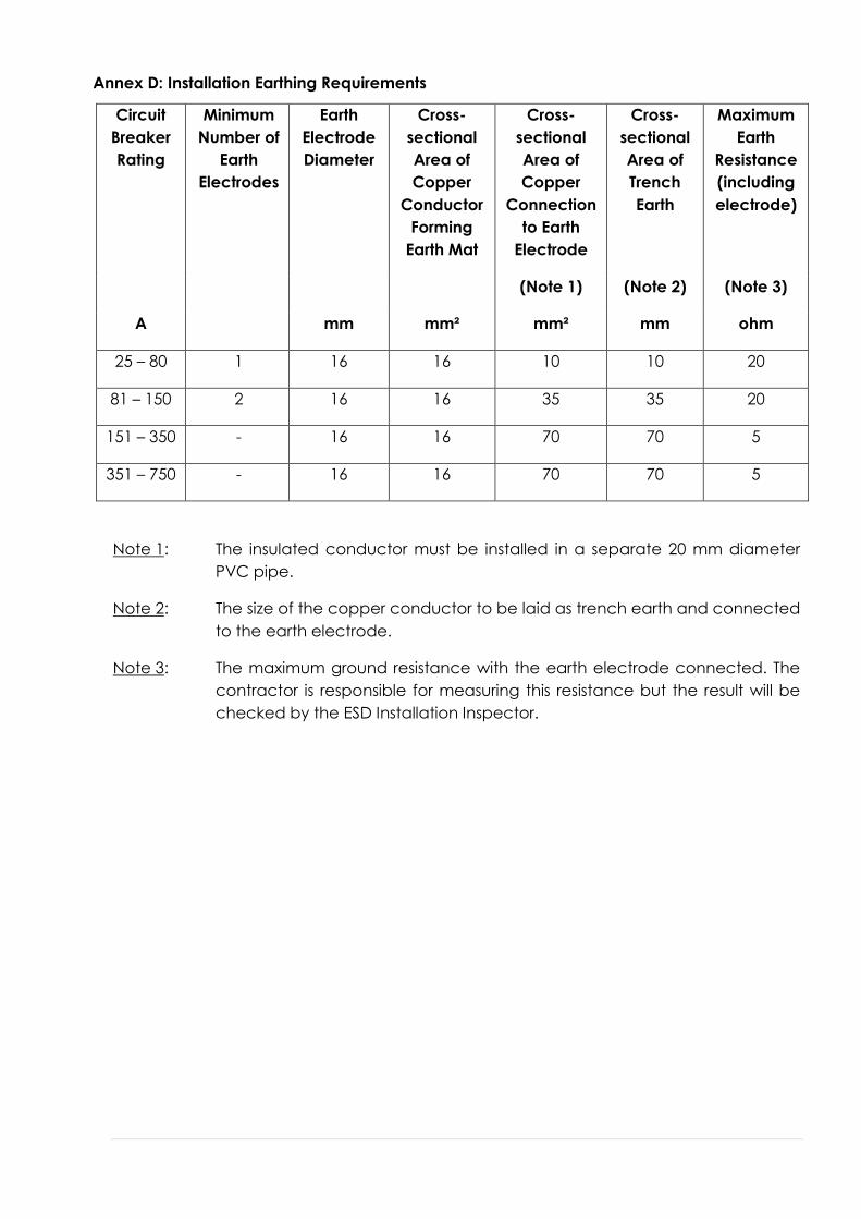
Annex D: Installation Earthing Requirements
Circuit
Breaker
Rating
Minimum
Number of
Earth
Electrodes
Earth
Electrode
Diameter
Cross-
sectional
Area of
Copper
Conductor
Forming
Earth Mat
Cross-
sectional
Area of
Copper
Connection
to Earth
Electrode
Cross-
sectional
Area of
Trench
Earth
Maximum
Earth
Resistance
(including
electrode)
(Note 1) (Note 2) (Note 3)
A mm mm² mm² mm ohm
25 – 80 1 16 16 10 10 20
81 – 150 2 16 16 35 35 20
151 – 350 - 16 16 70 70 5
351 – 750 - 16 16 70 70 5
Note 1: The insulated conductor must be installed in a separate 20 mm diameter
PVC pipe.
Note 2: The size of the copper conductor to be laid as trench earth and connected
to the earth electrode.
Note 3: The maximum ground resistance with the earth electrode connected. The
contractor is responsible for measuring this resistance but the result will be
checked by the ESD Installation Inspector.
38 | P a g e
Annex E: Typical Earthing Arrangements for Supplies Exceeding 150 A
Figure E1: Earth Mat
Figure E2: Earth Electrodes in Triangular Formation

39 | P a g e
Figure E 3: Earth Electrodes in Straight Line
Note: Only to be used when space is limited
40 | P a g e
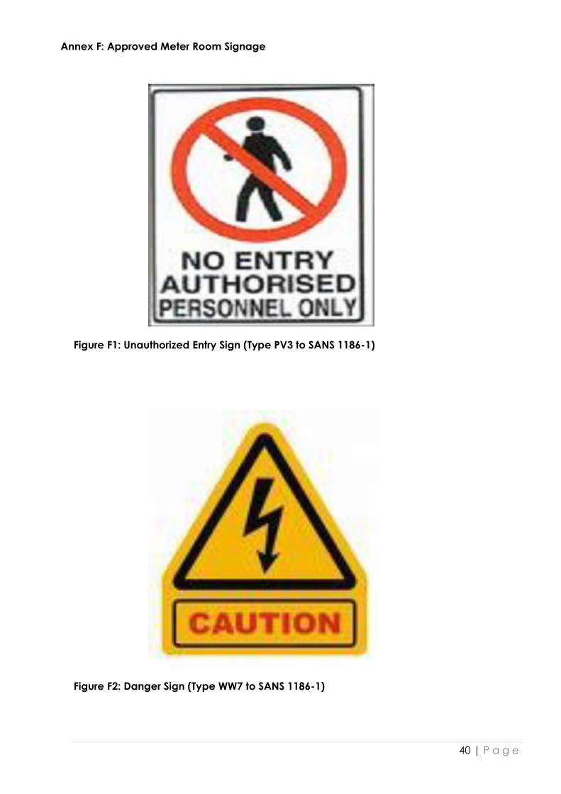
Annex F: Approved Meter Room Signage
Figure F1: Unauthorized Entry Sign (Type PV3 to SANS 1186-1)
Figure F2: Danger Sign (Type WW7 to SANS 1186-1)
41 | P a g e
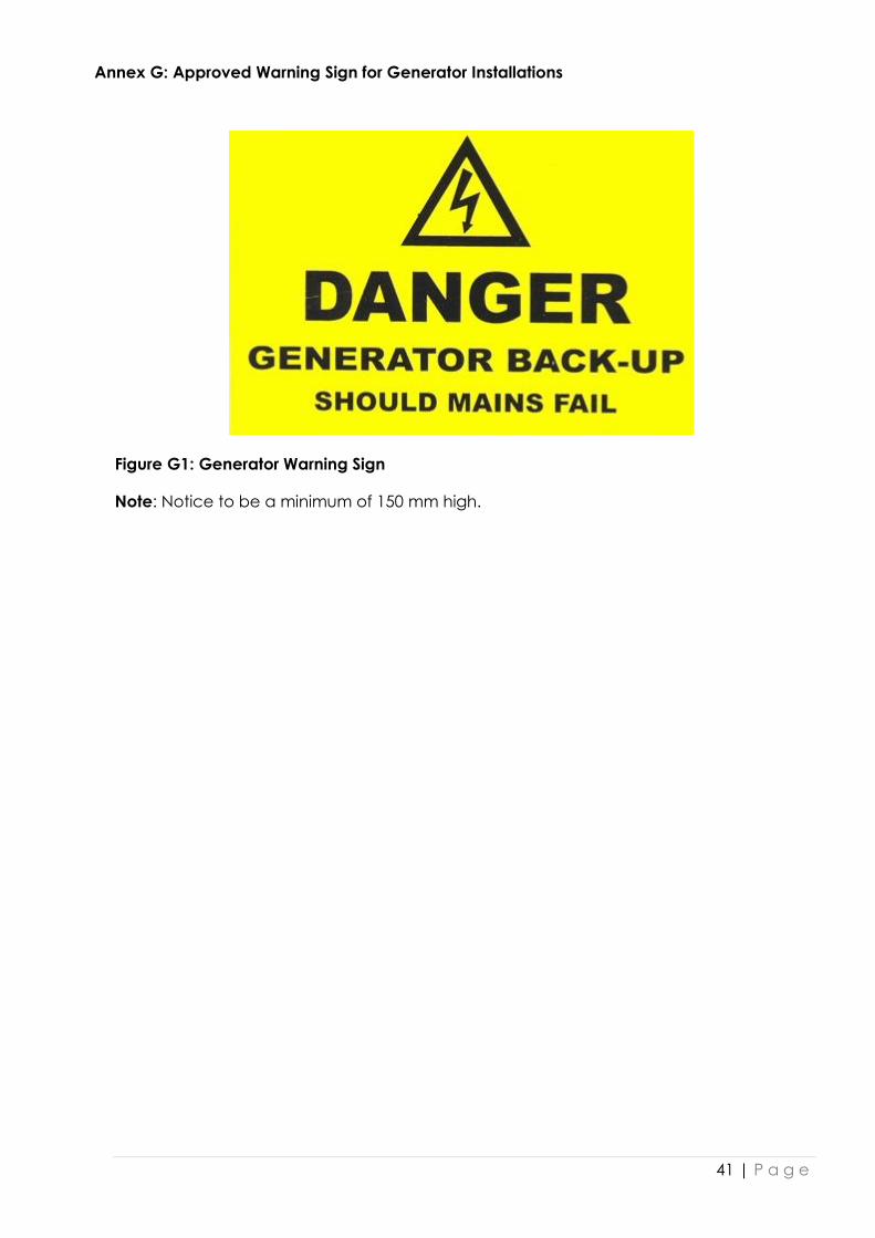
Annex G: Approved Warning Sign for Generator Installations
Figure G1: Generator Warning Sign
Note: Notice to be a minimum of 150 mm high.

42 | P a g e
Annex H: Connection of Standby Generator

43 | P a g e
Annex I: Customer Support Centres
1. Customer Support Services Offices: Customers, consultants, electrical contractors,
etc. requiring specific interactions with the Electricity Services Department can visit
one of the following City of Cape Town Electricity customer support centres
Office Location
ESD Head Office Bloemhof Road, Bellville
Wynberg Depot Rosmead Avenue, Wynberg
Vanguard Depot Klipfontein Road, Vanguard Estate
2. Customers may obtain or submit application forms at the following City Revenue
offices
Office Location
Athlone Office Civic Centre, Protea Street, Athlone
Atlantis Office Wesfleur Centre, Wesfleur Circle, Wesfleur
Belhar Housing Office Huguenot Square, Belhar
Bellville Office Civic Centre, Voortrekker Road, Bellville
Bellville South Office Community Centre, Kasselsvlei Road, Proteaville
Beacon Valley Office 42 Chrysler Crescent, Mitchells Plain
Blaauwberg Office Pienaar Road, Milnerton
Bloekombos Office Civic Centre, Sam Njokozela Avenue, Bloekombos
Brackenfell Office Municipal offices, cnr. Paradys & Old Paarl Road, Brackenfell
Cape Town Office Civic Centre, 2nd floor podium, Hertzog Boulevard, Cape Town
Delft Office Cnr. Delft & Voorburg Roads, Delft

44 | P a g e
Office Location
Durbanville Office Civic Centre, cnr. Queen & Oxford Street, Durbanville
Fezeka Office Municipal office, Lansdowne Road, Gugulethu
Fish Hoek Office Municipal office, Recreation Road, Fish Hoek
Goodwood Office Municipal offices, Voortrekker Road, Goodwood
Kraaifontein Office Municipal offices, Brighton Road, Kraaifontein
Kuils River Office Civic Centre, cnr Van Riebeek Road & Carinus Street, Kuils
River
Langa Office Washington Street, Langa
Lentegeur Office Municipal offices, Merrydale Street, Lentegeur
Macassar Office Municipal offices, Bind Avenue, Macassar
Manenberg Office Cnr Lansdowne, Vygiekraal & Wye Roads, Manenberg
Mfuleni Office Main Road, Mfuleni
Milnerton Office Municipal offices, 35 Pienaar Road, Milnerton
Nyanga Office Municipal offices, New Eisleben Road, Nyanga
Parow Office Civic Centre, Voortrekker Road, Parow
Plumstead Office Old Plessey Building, cnr. Main & Victoria Road, Plumstead
Resource Centre Makhabeni Street, A Section, Lingelethu, Khayelitsha
Rocklands Office Municipal offices, cnr. Spine & Caravelle Roads, Rocklands

45 | P a g e
Office Location
Site B Office Bonga Drive, Khayelitsha
Stocks & Stocks Office Ntlazane Street, Litha park, Khayelitsha
Strand Office Municipal offices, cnr. Fagan & Main Road, Strand
Somerset-West Office Municipal offices, cnr. Andries Pretorius & Victoria Road,
Somerset-West
Tuscany Glen Office 203 Blue Downs Road, Blue Downs
Westridge Office Municipal offices, cnr. Simon Sig & Wespoort Roads, Westridge

46 | P a g e
Annex J: ESD District Supply Areas
1. Atlantis Depot supply area

47 | P a g e
2. Bloemhof Depot supply area
48 | P a g e
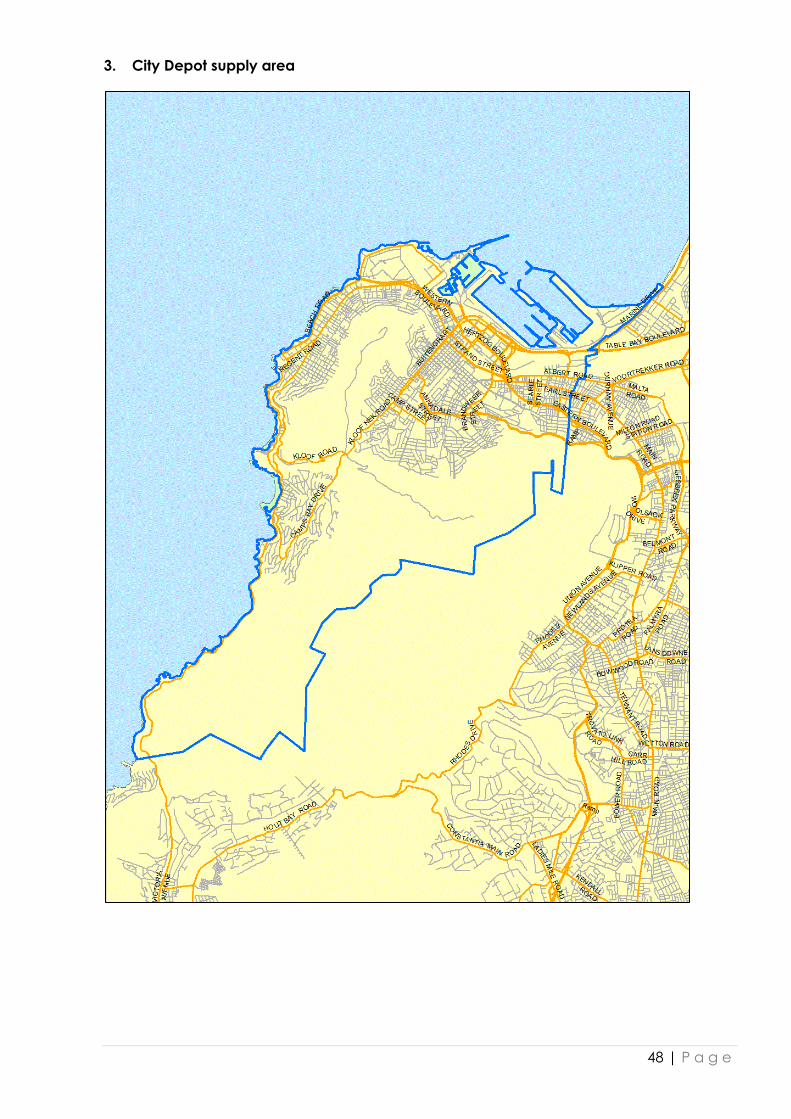
3. City Depot supply area
49 | P a g e
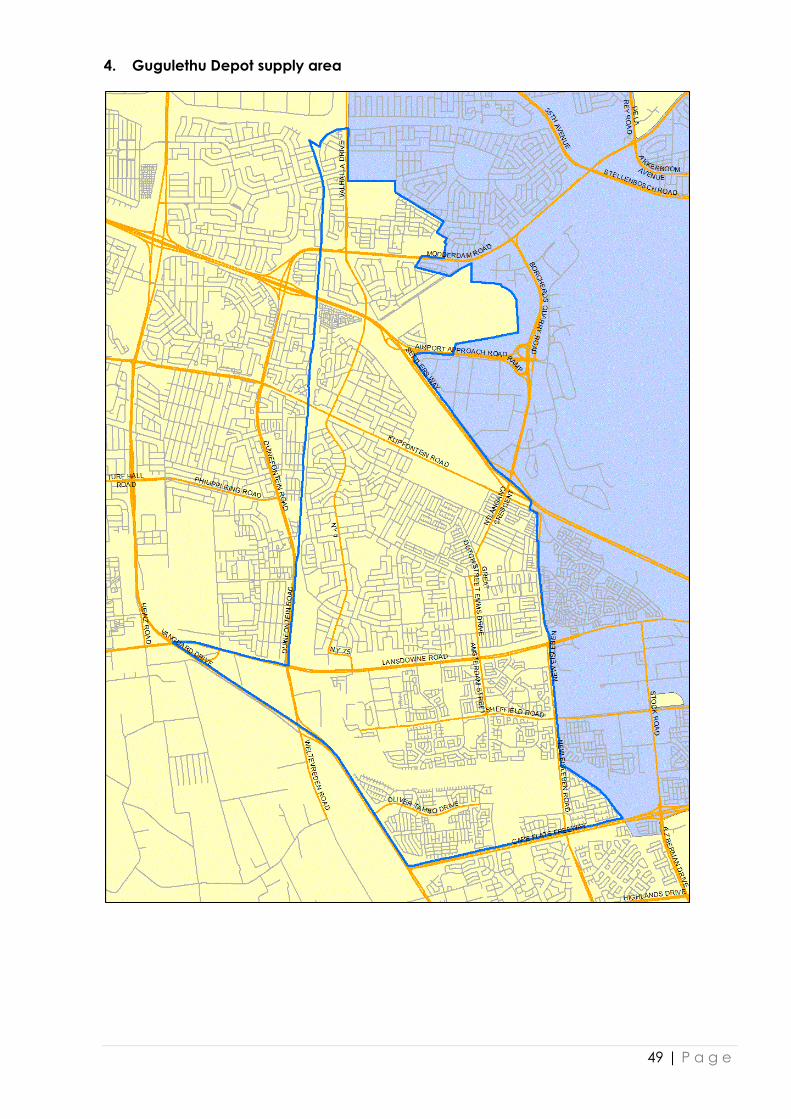
4. Gugulethu Depot supply area
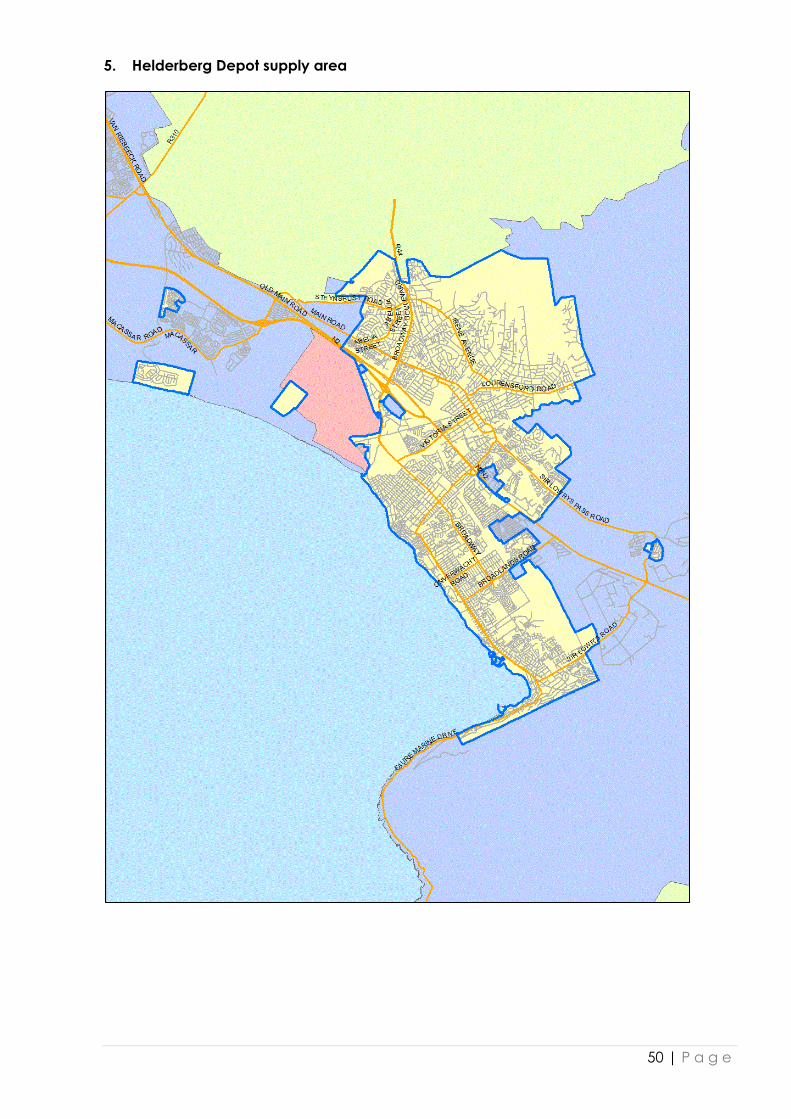
50 | P a g e
5. Helderberg Depot supply area

51 | P a g e
6. Mitchell’s Plain Depot supply area

52 | P a g e
7. Mowbray Depot supply area

53 | P a g e
8. Muizenberg Depot supply area
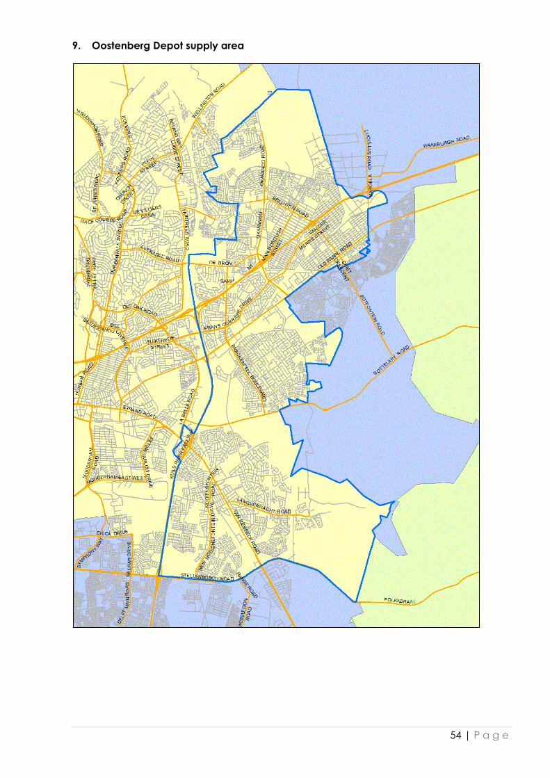
54 | P a g e
9. Oostenberg Depot supply area

55 | P a g e
10. Parow Depot supply area

56 | P a g e
11. Vanguard Depot supply area

57 | P a g e
12. Wynberg Depot supply area

Annex K: Inspector Contact Details
DISTRICT NAME EMAIL ADDRESS
OFFICE
TELEPHONE
ADMIN
TELEPHONE FAX
Vanguard Edward Abrahams [email protected] 021 630 1107 021 630 1100 021 638 3280
City Mustapha Banderker [email protected] 021 488 1345 021 488 1359 021 488 1355
Helderberg Leon Bothma [email protected] 021 840 2608 021 840 2612 021 840 2580
Mowbray Joseph Dongo [email protected] 021 514 4284 021 506 4820 021 514 4290
Parow Dennis Bronkhorst [email protected] 021 417 4811 021 938 8111 086 576 0879
Bloemhof Steven De Vries [email protected] 021 918 7068 021 918 7062 021 918 7505
Muizenberg Edwin Dodgen [email protected] 021 788 8964 021 788 8961 086 546 2996
Oostenberg Jacques Maree [email protected] 021 417 0627 021 417 0629 021 417 0633
Mowbray Moegsien Mohamed [email protected] 021 514 4266 021 506 4820 021 514 4290
Guguletu Mzoxolo Mzamo [email protected] 021 380 5027 021 380 5001 021 386 7651
Helderberg Ian Pollock [email protected] 021 840 2613 021 840 2612 021 840 2580
Wynberg Clive Samuels [email protected] 021 763 5625 021 763 5691 021 763 5707
Atlantis Hermias Schreuder [email protected] 021 573 7007 021 573 7014 086 530 1662
City Wayne Scott [email protected] 021 488 1346 021 488 1359 021 488 1355
Parow James Strauss [email protected] 021 417 4812 021 938 8111 086 576 0878
Mitchell's Plain Ricardo Williams [email protected] 021 371 6151 021 371 5161 021 371 0640