guideline for radiation protection and performance evaluation
TRANSCRIPT

NUCLEARMALAYSIA/L12010/47
GUIDELINEFOR RADIATION PROTECTION ANDPERFORMANCE EVALUATION OF
PET-CT IMAGING
Dr Noriah Jamal & Dato' Dr Rehir Dahalan
MALAYSIAN NUCLEAR AGENCY1ST SEPTEMBER 2010
1
N UCLEARMALAYSIA/L/2010/47
Contributors:
Dr. Muhd Noor Muhd Yunus - MalaysiaDato' Dr. Mohd Ali Khader - MalaysiaProf. Dr. Ahmad Zakaria - MalaysiaProf. Dr. Chen Shengzu - ChinaDr. I-Iideo Murayama - JapanMr. Tran Ngoc Toan - VietnamAsso. Prof. Dr. Rujaporn Chanachai -ThailandMr. Alexis Tiongson De Leon - The PhilippinesProf. Dr. Kwan-Hoong Ng - MalaysiaAsso. Prof. Dr. Wan Ahmad Kamil - MalaysiaMr. Ng Aik Hao - MalaysiaMr. Mohd Aminuddin Said - MalaysiaMr. Zunaide Kayun - Malaysia
2

NU CLEARMALAYSIA/L/2010/47
GUIDELINE FOR RADIATION PROTECTION AND PERFORMANCEEVALUATION OF PET-CT IMAGING
Table of contents
1 Introduction1.1 Scope of this document1.2 Care of patients undergoing medical imaging procedures
2 Radiation protection in PET-CT imaging2.1 Principles of safe radiation protection
2.1.1 General principles2.1.2 The justification of practice2.1.3 The optimisation of protection2.1.4 Individual dose limits
2.2 Medical exposures2.2.1 The justification of practice2.2.2 Optimization2 .2.3 Dose limits
2.3 Radiation shielding for PET-CT facility design2.3.1 Shielding requirements2.3.2 Shielding assessment2.3.3 Radiation warning sign2.3.4 Personnel present during PET-CT examination2.3,5 Markings on CT x-ray generators and tube assemblies
3 Acceptance testing3.1 When acceptance testing of PET-CT scanner perform3.2 Standard of acceptance testing of PET scanner3.3 Acceptance testing and data analysis
4 Performance characteristics of PET-CT4.1 Quality control procedures4.2 Qualifications and responsibilities of a nuclear medicine physicist
4.2.1 Qualifications4.2,2 Responsibilities
4.3 Performance evaluation of PET scanner4.3.1 Performance characteristics to be monitored
4.4 Performance evaluation of CT scanner4.4.1 Performance characteristics to be monitored4.4.2 CT baseline values4.4.3 Diagnostic reference levels
4.5 Specific Tests for PET-CT
Page

NUC LEARMALAYS IA/U2010/47
4.5.1 Overall performance 144.5.2 Patient radiation dose: CT only 144.5.3 Organ doses from radiopharmaceuticals : PET only 14
5 Documentation 155.1 QC report and follow- up procedures 155.2 Record keeping 15
6 References
7 Appendices
Appendix A: TerminologyAppendix B: Performance evaluation tests, tolerances and checklists for CTAppendix C: Performance evaluation tests, tolerances and checklists for PETAppendix D: Daily and quarterly QC tests for PET-CT
16
4
N UCLEARMA LAYS IA/L'2010/47
1 Introduction
1. 1 Scope of this document
Positron emission tomography - computed tomography (PET-CT) system is a new imagingtool in the nuclear medicine department. The primary goal of PET-CT imaging is to producehighly accurate fusion images with proper registration of both CT and PET images on thesame platform. An additional goal is to produce images with the lowest reasonable radiationdose consistent with the clinical use of the equipment.
Even though they can be operated to acquire either CT images or PET images, they aremainly operated to acquire both, combining two medical imaging technologies: X-ray CT foranatomical imaging, and attenuation correction and PET for functional imaging. This bringsthe advantages and also the complexities of both systems while providing anatomical andfunctional aspects through fusion images.
Therefore, PET-CT scanner shall be tested on installation and monitored by a NuclearMedicine Physicist to ensure proper functioning within the manufacturer ' s specifications andaccepted performance standards.
The scope of this document is to present a guideline on radiation protection related to the useof PET-CT scanner and the performance evaluation of this imaging device.
The objectives of this guideline are to:a. provide adequate safety measures to protect patients, occupationally exposed
personnel and the public from unnecessary radiation exposure from PET-CTimaging
b. improve and maintain the quality of clinical data acquired using PET-CT scannerc, ensure that minimum standard of PET-CT scanner performance is achieved.
This guideline should be read in conjunction with all related rules and regulations enforced.It is important that the performance level of the scanner is established during acceptancetesting, and that performance standards are maintained over time by an appropriate qualitycontrol program. Inadequate performance and quality control procedures may cause anunnecessary increase in dose to the patient and staff, and a decrease in the diagnostic value ofthe examination.
1.2 Care of patients undergoing medical imaging procedures
1.2.1 Nuclear medicine physicians, radiologists, nuclear medicine physicists, nuclearmedicine technologists, and all supervising physicians have a responsibility to minimizeradiation dose to individual patients, to staff, and to society as a whole, while maintaining thenecessary diagnostic image quality. This concept is known as "as low as reasonablyachievable (ALARA)."
5

NUCLEARMALAYS IA/L12010/47
1.2.2 Facilities , in consultation with the nuclear medicine physicist , should have in placeand should adhere to policies and procedures , in accordance with ALARA, to varyexamination protocols to take into account patient body habitus, such as height and/orweight, body mass index or lateral width.
1.2.3 The dose reduction devices that are available on imaging equipment should be active.If not, manual tecluiiques should be used to moderate the exposure while maintaining thenecessary diagnostic periodically measured by a nuclear medicine physicist in accordancewith the appropriate standards.
2. Radiation protection in PET-CT imaging
2.1 Principles of safe radiation protection
2.1.1 General principles
2.1.1.1 Radiation protection is based on principles defined by the International Commissionon Radiological Protection (ICRP). Three general principles apply to safe radiationpractice, namely justification of practice, optimization of protection and individual doselimits.
2.1.2 The justification of practice
2.1.2.1 No practice shall be adopted unless its introduction produces a positive net benefit tothe exposed individuals.
2.1.3 The optimisation of protection
2.1.3.1 In relation to a particular practice , the magnitude of individual dose, the number ofpeople exposed , and the likelihood of incurring exposure , shall be kept as low as reasonablyachievable (usually referred to as the ALARA principle), economic and social factors beingtaken into account.
2.1.3.2 This should be an over-riding principle in all aspects of radiation protection whenusing ionising radiation for imaging purposes. As a result, all practices where ionisingradiation emitting devices are used for imaging purposes shall be designed so as to reduce toa reasonable level:(a) the undesired exposure of individuals from radiation,(b) the risk of equipment failure leading to an uncontrolled exposure,(c) the occurrence of errors when in use.
6

N U C L E A RM A LA Y S I A /L/2 010/47
2.1.4 Individual dose limits
2.1.4.1 The effective and equivalent dose to individuals shall not exceed the limits defined inthe IAEA Basic Safety Standards.
2.1.4.2 These objectives are in general achieved by a combination of engineering designfeatures of the equipment, facility and administrative procedures.
2.2 Medical exposures
2.2.1 The justification of practice
2.2.1.1A patient may be exposed to radiation for medical imaging purposes with thepatient ' s approval when in the professional judgement of the nuclear medicinephysician or other authorised medical practitioner , the proposed usage of radiation will beof net benefit to the patient.
2.2.2 Optimization
2.2.2.1 Optimization of the protection of the patient should take place by proper protectiondesign, operation and quality assurance. In addition, protecting the patient requiresoptimization of the imaging procedure as a whole to deliver adequate dose to the diseasedtissues and to reduce unwanted radiation dose to other tissues to as low as reasonablyachievable, economic and social factors being taken into consideration.
2.2.3 Dose Limits
2.2.3.1 Dose limits do not apply to medical exposures, since the total benefit of the exposureis directed to the individual exposed, and because of the individual medical requirementsof each patient.
2.3 Radiation shielding for PET-CT facility design
2.3.1 Shielding requirements
2.3.1.1 Special care must be exercised regarding radiation shielding requirements for PET-CT facility design . Appropriate shielding must be provided for patient injection /uptakerooms, PET-CT imaging suites , and any other areas where PET radiopharmaceuticals areprepared , used , or stored.
2.3.1.2 Due to the high energy of annihilation radiation used in PET, the amount of shieldingmaterials needed to protect adjacent areas is typically much larger than that for conventionalCT scanners or other diagnostic imaging modalities including conventional nuclear medicineimaging.
7

N U CLEARMALAY SIA/L/2010/47
2.3.1.3 A nuclear medicine physicist should be consulted early in facility design planningstages so that shielding requirements can be determined and structural design issues, createdfrom using the larger amounts of shielding can be assessed. The design and shieldinginformation should be forwarded to the appropriate authority for the licensing purposes.
2.3.1.4 Appropriate radiation shielding should be provided for the doors, walls, floor andceiling of the room in which the PET-CT scanner is installed and for any protective barrierintended for use as a shield for the operators, to ensure that the radiation dose to anypersonnel is as low as reasonably achievable.
2.3.1.5 Where a fixed protective shield is provided for use by the operator it must, in the caseof new installations, be clearly and durably marked with the lead equivalent and the kVp ofthe x-ray beam at which the lead equivalent was measured.
2.3.1,6 Where a viewing window is used as part of the protective shield the lead equivalentand the kVp of the x-ray beam at which the lead equivalent was measured must, in the caseof new installations, be clearly and durably marked on the viewing window.
2.3.2 Shielding assessment
2.3.2.1 Specifications for radiation shielding of protective barriers and the design details ofrooms used for PET-CT scanner should be determined and documented by the nuclearmedicine physicist before building works start.
2.3.3 Radiation warning sign2.3.3.1 A radiation warning sign complying with the IAEA safety standards regulation mustbe displayed on the outside of the entry doors to any room housing a PET-CT scanner,
2.3.3.2 A radiation warning light must be positioned at the entry doors to a rooms housingPET-CT scanner.
2.3.3.3 Where a radiation warning light is provided, it should illuminate whenever thex-ray tube is placed in the preparation mode before exposure or when exposure is inprogress. The light must remain illuminated for the duration of the exposure and must bearthe words `X-RAYS-DO NOT ENTER' or similar. Immediate illumination should beensured,
2.3.4 Personnel present during PET-CT examination
2.3.4.1 The operator should ensure that no personnel , other than the patient , remains in the x-ray room during an exposure , unless the personnel is behind a protective screenor is wearing a protective apron.
8

NUCLEARMALAYSIA/IJ2010/47
2.3.4.2 The only personnel who should be present in the room during the scanning are those:(a) whose presence during the procedure is necessary, or(b) who are responsible for the care of the patient, or(c) who are receiving instruction from the personnel conducting the procedure.
2.3.5 Markings on CT x-ray generators and tube assemblies
2.3.5.1 X-ray generators and tube assemblies must be permanently marked and the markingsmust be clearly visible.
2.3.5.2 X-ray generators must bear the following markings:(a) the name or trademark of the manufacturer(b) the type or model number(c) the serial number or registration number,
2.3.5.3 X-ray tube assemblies must bear the following markings on the outer side ofthe tube housing:
(a) the name or trademark of the manufacturer of the x-ray tube insert(b) the type or model number of the x-ray tube insert(c) the serial number of the x-ray tube insert(d) the name or trademark of the manufacturer of the x-ray tube housing(e) the type or model number of the x-ray tube housing(f) the serial number of the x-ray tube housing
3 Acceptance testing
3.1 When acceptance testing of PET-CT scanner perform
3.1.1 Acceptance testing of PET-CT scanner shall be performed upon installation andshould be completed before clinical use.
3.2 Standard of acceptance testing of PET scanner
3.2.1 Acceptance testing and data analysis of the PET scanner should be done according tothe procedures in the appropriate National Electrical Manufacturers Association (NEMA)publication.
3.3 Acceptance testing and data analysis
3.3.1 Acceptance testing and data analysis of the CT scanner should be done according toAppendix B.
9

NUCLEARMALAYSIA/L12010/47
4 Performance characteristics of PET-CT
4.1 Quality Control procedures
4.1.1 Quality control (QC) procedures approved by a nuclear medicine physicist must beinstituted and maintained properly. The procedures should ensure that consistent, optimum-quality images are produced while the exposure of patients, staff and the public to radiationsatisfies the `as low as reasonably achievable' principle.
4.1.2 The QC procedures should include checks and test measurements on all parts of theimaging system, as indicated in this guideline.
4.1.3 The nuclear medicine physicist must design quality control procedures that includeregular testing procedures to insure proper operation on a daily basis. Quarterly testing with a3D phantom for uniformity, resolution, and contrast is recommended.
4.1.4 The QC activities for PET-CT should be reviewed regularly.
4.1.5 The test results must be reviewed by the nuclear medicine physicist and documentedin an annual survey reports.
4.1.6 Each facility is required to submit a summary of the quality control and frequency oftesting currently being done on each PET-CT unit to the appropriate authority.
4.2 Qualifications and Responsibilities of a Nuclear Medicine Physicist
4.2.1 Qualifications
4.2.1.1 A nuclear medicine Physicist is an individual who is competent in applying thephysics knowledge in nuclear medicine.
4.2.1.2 The nuclear medicine physicist may be assisted by properly trained individuals inobtaining QC data. However, the ultimate responsibility is on the nuclear medicine physicist.
4.2.2 Responsibilities
4.2.2.1 The nuclear medicine physicist must be familiar with the principles of imagingphysics and radiation protection; laws and regulations pertaining to the use of the equipmentbeing tested; the function, clinical usage, and performance specifications of the imagingequipment; and calibration processes and limitations of the instruments and the techniquesused for testing performance.
4.2.2.2 A nuclear medicine physicist has to ensure that instruments used for routine radiationdosimetry or equipment performance monitoring should have a current calibration certificatethat is traceable to an appropriate national standard.
10

NUCLEARMALAYS IA/L+2010/47
4.3 Performance evaluation of PET scanner
4.3.1 PET characteristics to be monitored
4.3.1.1 The performance evaluation procedures should include as a minimum, thoserecommended by the manufacturer. The following characteristics shall be evaluated for theequipment to which they apply on at least an annual basis:
a. Spatial resolutionb. Count rate performance (count rate versus activity), including count loss
correction. Specific measurements of the following are recommended.a. Total coincidencesb. Random coincidencesc. Scatter coincidencesd. Net true coincidencese. Noise equivalent count rate
c. Sensitivity (kcps/ kBq )d. Scatter Fraction (SF)e. Image quality, accuracy of attenuation and scatter corrections
4.31.2 Performance evaluation tests, tolerances and checklists for PET equipment is shownin Appendix C.
4.4 Performance evaluation of CT scanner
4.4.1 Characteristics to be monitored
4.4.1.1 Performance of each CT unit must be monitored at least annually. This evaluationshould include, but not be limited to:
1. Alignment light accuracy2. Alignment of table to gantry3. Multiple-row detector assembly and available scan modes4. Slice localization from scanned projection radiograph (localization image)5. Table increment accuracy6. Slice thickness7. Image quality
a Spatial resolutionb. Low-contrast resolutionc. Image uniformityd. Noisee. Artifact evaluation
8. CT number accuracy and linearity9. Display devices.
a. Image display monitor(s)b. Hardcopy display unit(s), if available
11

NUCLEARMALAY SIA/L12010/47
10. Dosimetrya. CT dose index (CTDI)b. Patient radiation dose for representative examinationsc. Review of pediatric dose reduction protocolsd. Monitoring of pediatric specific (typically weight-based) doses
11. Safety evaluationa. Visual inspectionb. Work load assessmentc. Scatter radiation measurementsd. Audible and visual signalse. Posting requirements
12. Other tests as required by state and/or local regulations
4.4.2 CT baseline values
4.4.2.1 Baseline values for noise, mean CT number, uniformity, slice thickness, high contrastresolution and CT dose index should be established at the start of operation and followingany maintenance likely to affect these parameters.
4.4.2.2 Values for parameters in clause 4.4.2.1 should be defined using the appropriateimage quality phantoms for all field sizes.
4.4.2.3 Deviations from baseline values should not exceed those given in Table 1.
12

NUCLEARM A LAY SIA/IJ2010147
Table 1 Acceptable deviations from CT baseline levels
Parameter Deviation
Noise ± 10% or 0.2 HU* (whichever is greater)
Mean CT number ±4 HU
Unifonnity ± 2 HU
Slice thickness ± 1.0 mm for thicknesses > 2.0 mm or f50% for thicknesses < 2.0 nun
Dose index ± 20%
High-contrast resolution ± 15% modulation
Couch positioning ± 2.0 mm
* HU = Hounsfield unit
4.4.3 Diagnostic reference levels
4.4.3.1 Dose exposure evaluation of CT procedures should be conducted as part of the QAprogram.
4.4.3.2 Dose levels that consistently exceed those in Table 2 should be investigatedand justified.
13

NUCLEARMALAYSIA/L/2010/47
Table 2 Some diagnostic guidance levels for CT procedures'
Examination CT Dose Indexw (mGy)* Dose Length Product (mGyem
Routine Head 60 1050
Routine Chest 30 650
Routine Abdomen 35 780
Routine Pelvis 35 570
Pediatric 25*EC, Report EUR 16262, European Guidelines on Quality Criteria for ComputedTomography, 1999.
4.5 Specific tests for PET-CT
4.5.1 Overall performance
4.5.1.1 The performance of either the PET or the CT systern can affect the overallperformance of dual-modality imaging. Each system should be tested individually, as statedpreviously, and together to examine co-registration. For this purpose, specially designedphantoms shall be scanned on both the PET and CT systems.
4.5.1.2 Accuracy of co-registration should be determined by established procedure.
4.5.2 Patient radiation dose: CT only
4.5.2.1 Patient radiation dose represented by CTDI shall be evaluated at least annually.
4.5.2.2 Doses to adult and pediatric patients (if performed) for CT examinations (e g., head,thorax, abdomen, pelvis, and whole-body) shall be assessed. These results shall be comparedwith appropriate guidelines or recommendations when they are available. Appropriate stepsshould be taken if the reference doses are not consistent with the recommendations.
4.5.3 Organ doses from radiopharmaceuticals : PET only
4.5.3.1 The activity of radiopharmaceuticals used must be optimum so that the dose to apatient is optimum without compromising the quality of the image.
14
NUCLEARMALAYSIA/L12010147
5 Documentation
5.1 QC report and follow-up procedures
5.1.1 The nuclear medicine physicist shall report the findings to the physician(s), to theresponsible professional(s) in charge of obtaining or providing necessary service to theequipment.
5.1.2 The head of department should take immediate action by direct verbalcommunication if there is imminent danger to patients or staff using the equipment due tounsafe conditions.
5.2 Record keeping
5.2.1 A record of maintenance and QC test results should be kept for each item of radiationapparatus. Information on any defects found and their repair must be included.
5.2.2 Records should include necessary information to allow retrospective dose assessment.
5.2.3 All QC records, including faults, modifications and maintenance, must be madeavailable to the appropriate authority on request.
5.2.4 Written survey reports shall be provided in a timely manner consistent with theimportance of any adverse findings.
6 References
American Association of Physicists in Medicine Task Group 108 report "PET and PET-CTShielding Requirements," in conjunction with the National Council on Radiation ProtectionReport 147, should be used as a reference in determining PET-CT shielding requirements.
American Association of Physicists in Medicine (AAPM). Specification and AcceptanceTesting of Computed Tomography Scanners. College Park, Md: American Association ofPhysicists in Medicine; AAPM Report 39, 1993.
American College of Radiology. ACR technical standard for medical nuclear physicsperformance monitoring of pet-ct imaging equipment. In: Simmons G, Dahlborn M, eds.Practice Guidelines and Technical Standards, 2008. Reston, VA: American College ofRadiology; 2008:1155-1159.
American College of Radiology. Nuclear medicine/PET accreditation program requirements.Available at: http://www.acr.orgls acr/bin.asp?CID51744&DIDS 12152&DOC5FILE.PDF.
15

N UCLEARMALAYSIA/U2010/47
Australian Radiation Protection and Nuclear Safety Agency & National Occupational Health& Safety Commission , 2002, Recommendations for Limiting Exposure to Ionizing Radiation(1995) (Guidance Note [NOHSC:3022(1995J) and National Standard for Limiting Exposureto Ionizing Radiation [NOHSC:1013(1995)], Radiation Protection Series Publication No. 1,ARPANSA, Yallambie, Victoria.
Brambilla M, Secco C, Dominietto M, Matheoud R, Sacchetti G, Inglese E. Performancecharacteristics obtained for a new 3-dimensional lutetium oxyorthosilicate-based whole-bodyPET/CT scanner with the National Electrical Manufacturers Association NU 2-2001standard. JNucl Med 2005;46:2083-209 1.
Carolyn Richards MacFarlane, BS ACR Accreditation of Nuclear Medicine and PETImaging Departments. J Nucl Med Technol 2006; 34:18-24.
European Commission, 1999, European Guideline on Quality Criteria for ComputedTomography, Report EUR 16262 EN.
Mawlawi 0, Podoloff DA, Kohlmyer S, et al. Performance characteristics of a newlydeveloped PET/CT scanner using NEMA standards in 2D and 3D modes. J Nucl Med2004;45:1734-1742.
National Council on Radiation Protection and Measurements (NCRP). Structural ShieldingDesignfor Medical X-Ray Imaging Facilities . NCRPBethesda , Md; 147; 2004.
National Electrical Manufacturers Association . NEM4 NU 2-2008 PerformanceMeasurements of Positron Emission Tomographs. Available at: http://www.nema.org/media/pr/20070627b.efm. Accessed July 26, 2008.
Surti S, Kuhn A, Werner ME, Perkins AE, Kolthammer J, Karp JS. Performance of PhilipsGemini TF PET/CT scanner with special consideration for its time-of-flight imagingcapabilities. JNucl Med 2007;48:471-480.
Townsend DW, Beyer T. A combined PET/CT scanner: the path to true fusion. Br I Radiol2002;75:S24-S30.
Townsend DW, Carney JP, Yap JT, Hall NC. PET/CT today and tomorrow. J Nucl Med2004;45:4S-14S.
16
NUCLEARMALAYSIA/L/2010/47
Appendix A - Terminology
absorbed dose. Energy delivered from radiation per unit mass of absorbing material,measured in Gray (Gy) or mGy. One Gray equals one joule per kilogram,
acceptance testing. Testing prior to delivery of a system.
air kerma . Kinetic Energy Release per Unit Mass (KERMA) measured in a mass of air.
analog-to-digital converter (ADC). These devices convert continuous electrical voltages todiscrete integer numbers in a defined range. When a digital image is acquired from an analoggamma camera an ADC converts the electrical signal that represents the x and y positions fora detected photon to a matrix location in the ranges of, for example, 1-64 or 1-128.
annihilation photons. When a positron is emitted it travels a short distance in tissue, losingenergy. It eventually combines with an electron and the two annihilate (disappear), with themass being converted into energy in the form of two gamma rays (511 keV) that travel inopposite directions.
asymmetric energy window. Normally, the energy window is centred on the main peak(s)of the radionuclide being imaged. To reduce scatter, an offcentre energy window, shifted upon the peak, is sometimes used. This is referred to as an asymmetric window.
axial field-of-view (FOV). The maximum length parallel to the long axis of a positronemission tomograph along which the instrument generates transaxial tomographic images.
back-projection . This is the process used in reconstruction, which allocates counts in thereconstructed image at each voxel proportional to the number of recorded counts on theprojection, defined by the geometry of detection, In the simplest case assuming a parallelhole collimator, each voxel will be allocated counts from a projection pixel, defined by a linedrawn at right angles to the projection that passes through the voxel.
bismuth germanate oxide. This is a detector material commonly used in PET cameras. Ithas a higher density than Nal and is therefore well suited to detection of the high energy (511keV) annihilation photons.
centre of rotation . This defines the point that should correspond to the exact centre aroundwhich the detectors rotate; it should correspond exactly to the centre of the projectionsrecorded at all angles. Any error in this point will lead to loss of resolution.
coincidence detection . In order to detect the two gamma rays emitted from a positronannihilation event, two detectors are used and a valid event is recorded when both detectorsrecord an interaction at the same time (or within a very short time of each other). The
17

NUCLEARMALAYSIA/LJ2010/47
detectors operate in electronic coincidence. This term is used with detectors in dedicated PETsystems as well as in gamma camera based PET systems.
convolution . Convolution is the filtering procedure undertaken in the spatial domain. Itinvolves replacing each pixel value by a weighted sum of the neighbouring values and thevalue itself. The result will depend on the weighting values, usually resulting in a smootherimage (e.g. nine point smooth).
CT. This abbreviation stands for computed tomography.
CT dose index. The integral of the dose profile along a line perpendicular to thetomographic plane from -7T to +7T (where T is the nominal slice thickness), divided by theproduct of the nominal slice thickness and the number of tomograms (N) produced in a singlescan.CT number . The number used to represent the mean x-ray attenuation associated with eachelemental area of the CT image. It is normally expressed in Hounsfield units.
cut-off/critical frequency . The shape of a filter is defined by some mathematicalfunction, with the value 1 at zero frequency and lower values at progressively higherfrequencies. The cut-off or critical frequency is a parameter that defines the shape of thefunction, a lower cut-off frequency defining a curve that drops to zero faster, resulting in asmoother result. In the case of the Butterworth filter the cut-off frequency defines the pointwhen the amplitude reaches half the maximum value.
electronic collimation . Since annihilation photons travel in opposite directions, the origin ofthe annihilation can be defined by the straight line joining the points of detection of the twophotons without the need for conventional collimation.
energy spectrum . A plot of the number of gamma photons detected as a function of theenergy of the gamma rays. Such spectra are useful for setting energy windows with the pulseheight analyser and for observing the amount of scatter present.
energy window . Setting a lower and upper energy threshold, the energy window determineswhich gamma ray energies are accepted and displayed.
FOV. This abbreviation stands for field of view.
full width at half maximum (FWHM . This term refers to resolution measurements (e.g.spatial and energy resolutions). FWHM is usually measured from a profile through an imageof a line or point source, or, in the case of energy, from the energy spectrum of a singlegamma emitting radionuclide. The spread is due to resolution effects and is measured by thefull width of the profile at a point which is half the maximum height of the profile.contrast resolution . The ability to resolve different objects in the displayed image, when thedifference in attenuation between the objects and the background is large compared to noise.Also known as spatial resolution.
18

NU C LEA RMA LAY S I A/U2010/47
Kerma (K). Kinetic Energy Released in a material by ionising radiation and is determined asthe quotient of dE« by dm, where dE,, is the sum of the initial kinetic energies of all thecharged ionising particles liberated by uncharged ionising particles in a material of mass dm(K = dE,,/dm). The unit of kerma is the gray (Gy), or joule per kilogram.
Kerma rate . kerma per emit time and is determined as the quotient of dK by dt, where dK isthe increment of kerma in the time interval dt.
lead equivalent . The thickness of lead causing the same attenuation of a beam of a specifiedradiation quality as the material under consideration,
line source . A thin line (such as a capillary tube) filled with activity, which is used formeasuring resolution. The diameter of the line source should typically be 1 mm.
lutetium oxyorthosilicate (LSO). This is a new detector material currently being consideredfor PET systems.
mean CT number . The mean value of the CT numbers of all pixels within a certain definedregion of interest.
NEMA (National Electrical Manufacturers Association ). NEMA develops standardspecifications for imaging equipment including gamma cameras (SPECT) and PET. Theseform the basis for specification and acceptance testing of equipment, and some tests, withmodification, can also be used for routine quality control.
noise. The variation of CT numbers from a mean value in a defined area in the image of auniform substance.
noise equivalent count rate (NEC). Noise equivalent Count rate used to estimate thenumbero f true count acquired per sec exempt of scatter, randoms and intrinsic contributions.
performance evaluation tests . Those tests which are undertaken either regularly, or aftermaintenance or repairs, to detect whether any changes in the performance of the equipmenthas occurred. They are also referred to as quality control
phantom . A test object that simulates the average composition of various structures,
positron emission tomography (PET). Tomography based on detection of the dualannihilation photons that originate from positron emission. The technique involves detectionof the dual photons in coincidence (at the same time).
primary beam . A ionising radiation that emerges through the specified aperture of theprotective shielding of the x-ray tube and the collimating device.
projections (count profiles). This teen refers to the counts recorded during tomographicacquisition. The counts in a single row of the images recorded in SPECT at a given anglerepresent a projection of the emitted counts. These can also be referred to as count profiles.
19
NU CLEARMA LAYSIA /L2010/47
The set of projections, recorded at different angles, form the data that are used fortomographic reconstruction.
prompt counts . Count that represent coincidence events acquired in the standardcoincidence window of a positron emission tomograph. Prompt counts include true,scattered and random coincidence events.
quality assurance . The systematic process of checking to see whether a product or servicebeing developed is meeting specified requirements.
quality control . quality control (QC) is a procedure or set of procedures intended to ensurethat a manufactured product or performed service adheres to a defined set of performancecriteria.
random coincidence . When two gammas originating from quite independent sources (e.g.two separate positron emissions) are detected at the same time, the path defined by the pointsof detection does not correspond to a positron emission. This incorrectly located coincidenceevent is referred to as a random event.
resolution . This refers to the ability of imaging systems to distinguish between two closelyspaced small sources. Usually expressed in terms of FWHM, which describes the spread ofthe image obtained from a line or point source.
resolution recovery. This is the opposite of smoothing, and is achieved by filtering ordeconvolution. By use of an appropriate filter the loss of resolution due to some measurableeffect (e.g. due to a detector's finite resolution) can be partially recovered. However, anynoise in the original image will normally be amplified.
ring artefacts . These are a common error in reconstructed images which are caused by alocalized non-uniformity in the detector.
scatter coincidence . When one or both photons originating from a positron event aredetected in coincidence, the path defined by the points of detection does not necessarilycorrespond to the point of positron emission. This event is referred to as a scattercoincidence.
scatter fraction (SF). A dimensionless ratio of the scattered coincidence events to the sumof scattered and true coincidence events in a defined ROI of the scanner field-of- view
scattered photon. A gamma ray which has changed direction at least once due to Comptoninteraction and loss of energy in the material through which it is travelling.
scattered radiation . Ionising radiation produced from the interaction of electromagneticionising radiation with matter. It has a lower energy than, or different direction from, that ofthe original incident ionising radiation.
sensitivity . Fraction of the emitted gamma rays which pass through the collimator(collimator sensitivity) or are detected by the gamma camera (system sensitivity).
20

NUCLEARMALAYSI A/U2010/47
single event. In a PET system, when a photon is detected without a correspondingcoincident photon, this is referred to as a single event. Owing to the probability of detection,there are many more single events detected than coincidences.
sinogram . The image formed by placing projection values in sequential rows (i.e. arrangingpixels corresponding to projection position versus projection angle) is called a sinogram. It isso called since the projections from a single point describe a perfect sine wave when plottedin this form.
slit phantom . A phantom consisting of a lead mask with thin slits cut into it. Typically theslits are 1 mm wide and 30 mm apart. They are used for measuring intrinsic FWHMresolution and also linearity.
spatial frequency . Frequency normally refers to cyclic variations as a function of time(units: s-1). However, if a curve represents variations in values over distance (units:1/distance), the number of oscillations per unit distance is referred to as a spatial (rather thantemporal) frequency.
tomography . Literally this means `drawing a body slice'. Tomography involvesmeasurement from different angles around an object with the intention to `reconstruct' animage of the internal distribution of some parameter (e.g. activity in PET).
transverse field-of-view (FOV). The maximum diameter circular region perpendicular tothe long axis of a positron emission tomograph within which objects might be imaged,
true coincidence . When two annihilation photons originating from a single positronannihilation are detected in coincidence (without being scattered), this is referred to as a truecoincidence.
uniformity . A measure of how uniform the observed counts across the FOV are when thedetector is irradiated by a uniform source. Integral uniformity is a measure of the maximumcount deviation ((max - min)/(max + min)) over a given FOV. Differential uniformity is ameasure of the maximum rate of change over a specified distance. Both shall be measured forthe UFOV and the CFOV.
voxel. If one considers a digitized 3-D volume rather than a digitized 2-D image, each digitalvalue within the volume can be considered to occupy a small volume element (e.g. a smallcube) or voxel. One therefore refers to planar projections as having pixels, but to eachreconstructed slice as having voxels, which also have a thickness corresponding to thespacing between adjacent slices.
X-ray tube potential difference. The peak value of the potential difference applied to the x-ray tube, expressed as kilovolts peak (kVp).
21

NUC LEARMALAYSI A/L/2010/47
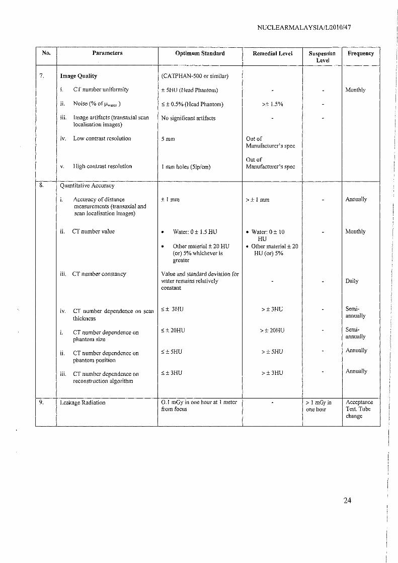
Appendix B - Performance evaluation tests, tolerances and checklists for CTThe schedule of tests and tolerances specified in this section's tables have been adopted frominternational literature and the tolerances should be regarded as a minimum standard for therange of equipment considered and the frequency determined. Manufacturer's tolerancespecifications may be used when they approximate the tabulated values.
No. Parameters Optimum Standard Remedial Level Suspension FrequencyLevel
I X-Ray Generator
Maximum deviation: <_ >±5%or±5kV >±20%or±20i. Accuracy of kVp
±5%or±5kV whichever is kV whichever is
whichever is smaller smaller smaller Annually
Max mum deviation >± 10% >± 25%H. Accuracy of exposure Time
i±10%
2. Radiation Dosimetry
i. Patient dosimetry (CTDI) <±20% of nominal >Baseline ± 20% >Baseline ± 50% Semi-annually
ii. Scout localisation image <_±20% of nominal >Baseline±20% >Baseline ± 50%
3. Scan Localization
i. Axial scan localisation light <±2mm >± 5mm -accuracy
ii. Isocenter alignment, sagittal and < f 5mm >±15mm -coronal localisation light accuracy
Annually
iii. Gantry (or table) tilt accuracy <± 3° of intended >± 3° -
iv. Table top incrementation 5 t 2mm in 20 cm >± 2mm in 20 cm -
v. Couch travel accuracy (spiral Scan) <±2mm in 20 cm >± 2mm in 20 cm
vi. Accuracy of scan prescription from <± Imm >± 1 mm `scout localisation image
4. Image Scan width (sensitivity >Optimum >± 50% of Annually
profile)± 20% of intended or ± standard intended1 mm whichever is
Single-slice CT • Greater for < 5 mmslice.
• Smaller for _ 5mm slice
>± 50% ofWithin Manufacturer's >± 20% of Manufacturer's
Multi-slice CT Spec Manufacturer's spec
spec
22
NUCLEA RMA LAY SIA/LI2010/47
No. Parameters Optimum Standard Remedial Level Suspension FrequencyLevel
7, Image Quality (CATPHAN-500 or similar)
i. CT number uniformity ± 5HU (Head Phantom) - - Monthly
ii. Noise (% of <± 0.5% (Head Phantom) >± 1.5% -
iii. Image artifacts (transaxial scan No significant artifacts - -localisation images)
iv. Low contrast resolution 5 mm Out ofManufacturer's spec
Out ofv. High contrast resolution I mm holes (51p/em) Manufacturer's spec
8. Quantitative Accuracy
i. Accuracy of distance ± 1 mm >+ I mm - Annuallymeasurements (transaxial andscan localisation images)
ii. CT number value • Water: 0 ± 1.5 HU • Water: 0±t0 - Monthly
HU• Other material ± 20 HU • Other material + 20
(or) 5% whichever is HU (or) 5%greater
iii. CT number constancy Value and standard deviation forwater remains relatively - - Dailyconstant
iv. CT number dependence on scan t 3HU >±31 1 1) - Semi-
thicknessannually
i. CT number dependence on <_±20HU >±2OHU - Semi-
phantom size annually
ii. CT number dependence on 5 *_ SHU > ± 5HU - Annually
phantom position
iii. CT number dependence on <_±3HU >±3HU - Annually
reconstruction algorithm
9. Leakage Radiation 0.1 mGy in one hour at 1 meter - > I m0y in Acceptancefrom focus one hour Test, Tube
change
24

NUCLEARMALAYSIA/L/2010/47
Appendix C - Annual performance evaluation tests, tolerances and checklists forPET
The schedule of tests and tolerances specified in the table below has been adopted frominternational literature and the tolerances should be regarded as a minimum standard for therange of equipment considered and the frequency determined. Manufacturer's tolerancespecifications may be used when they approximate the tabulated values.
No Parameter (s) ToleranceI . Scatter fraction ±10%2. Uniformity ±10%3. Correction for count losses and random ±10%4. Correction for attenuation and scatter ±10%5 spatial resolution ±10%6. Count rate performance ±10%7. Noise Equivalent Count Rate ±10%8. PET sensitivity ± 10%9. Image quality analysis ± 10%
25

Appendix D - Daily and quaterly QC tests for PET-CT
The tolerance is based on the manufacturer's specifications
Daily -Reboot the system- Coincidence timing resolution-Test of PET-CT in clinical mode
- Uniformity- PET normalization (blank scan)- 2D/3D activity concentration calibration- PET-CT fusion accuracy- Routine image quality PET/CT test- CT tube warmup- CT air calibration
Quarterly -Normalization- Well counter correction- Image quality analysis
NUCLEA RMALAY S IA/L/2010/47
26
I