guideline for seismic evaluation and rehabilitation of gas ...shaghool.ir/files/code606en.pdf ·...
TRANSCRIPT

Islamic Republic of Iran
Vice Presidency for Strategic Planning and Supervision
Guideline for seismic evaluation and rehabilitation
of gas supply systems
No. 606
Office of Deputy for Strategic Supervision
Department of Technical Affairs
nezamfanni.ir 2012


a Chapter five- Table of Content
Table of Content Page Number
Chapter 1- General
1-1-Generals ..................................................................................................................................................3
1-2-Goals .......................................................................................................................................................3
1-3-Scope of Work ........................................................................................................................................3
1-4-Target components ..................................................................................................................................3
1-5-Correlated Provisions and Standards ......................................................................................................4
1-6-Structure of the guideline ........................................................................................................................5
Chapter 2- Seismic Evaluation Procedure
2-1-Seismic Performance Evaluation Approaches ........................................................................................9
2-2-Pre Evaluation .......................................................................................................................................10
2-2-1-Effective Parameters in Performance Evaluation ..............................................................................10
2-2-2-Seismic hazard identification .............................................................................................................10
2-2-3-Seismic Vulnerability identification ..................................................................................................11
2-2-4-Seismic Performance .........................................................................................................................11
2-2-6-Planning for Evaluation Study ...........................................................................................................14
2-3-Seismic Evaluation Steps ......................................................................................................................20
2-3-1-Importance determination of element or System ...............................................................................20
2-3-2-Seismic Hazard Levels ......................................................................................................................20
2-3-3-Performance Level of System Elements ............................................................................................21
Chapter 3- Vulnerability Evaluation Methods
3-1-Target Components ...............................................................................................................................25
3-2-General Approach to Determine Vulnerability .....................................................................................25
3-3-Seismic Evaluation Methods of Components .......................................................................................26
3-3-1- Seismic Evaluation of Buildings ......................................................................................................27
3-3-2-Seismic Evaluation of Non-Building Structures ................................................................................28
3-3-3-Equipments' Seismic Evaluation .......................................................................................................28
3-3-4-Seismic Evaluation of Non-Structural Elements ...............................................................................28
3-3-5- Seismic Evaluation of Network and Pipelines ..................................................................................29
3-4-Inspection and Filling Worksheets in Level One Qualitative Evaluation .............................................29
3-5-Collection of Necessary Data for Evaluation in Level 2 and Level 3 ...................................................32
3-5-1-Design and Operation Documents' Collection ...................................................................................32
3-5-2-Visual Inspection and Extraction of Evident and Obvious Problems ................................................32
3-5-3-Conducting Soil Mechanics and Material Test and Risk Analysis ....................................................32
3-6-Seismic Evaluation Using Modeling and Numerical Analysis .............................................................33
3-6-1-Equivalent Static Method ..................................................................................................................33
3-6-2- Spectral Method ................................................................................................................................33
3-6-3-Time History Method ........................................................................................................................34
3-7-Seismic Interaction of Systems .............................................................................................................34
3-8-Acceptance Criteria ...............................................................................................................................34
3-8-1-Load Combinations ...........................................................................................................................34
3-8-2-Stability Controls ...............................................................................................................................35
3-8-3-Acceptance Criteria in Non Linear Dynamic Methods .....................................................................35

b Guideline for seismic evaluation and rehabilitation of gas supply systems
Chapter 4- Seismic retrofitting methods and procedures
4-1- Prioritizing retrofitting activities ......................................................................................... 39
4-2- Seismic retrofitting procedure ............................................................................................ 39
4-3-Retrofitting selection method approach ................................................................................. 39
4-4-Type of retrofitting method ................................................................................................. 40
Chapter 5- Seismic Retrofitting Methods for Refineries
5-Refinery ............................................................................................................................. 43
5-1-Piping and pipe supporting rack ........................................................................................... 43
5-1-1-Damage modes .............................................................................................................. 43
5-1-2-Seismic assessment ........................................................................................................ 50
5-1-3-Retrofitting of pipeline and pipe supports ........................................................................... 54
5-1-4-Execution safety and cost ................................................................................................ 59
5-2-Horizontal vessel .............................................................................................................. 60
5-2-1-Damage modes .............................................................................................................. 60
5-2-2-Seismic assessment flowchart ........................................................................................... 60
5-2-3-vessel retrofitting ........................................................................................................... 62
5-2-4-Retrofitting methods ....................................................................................................... 64
5-2-4-other countermeasure ...................................................................................................... 73
5-3-Tower and vertical tank ...................................................................................................... 74
5-3-1-Damage modes .............................................................................................................. 74
5-3-2-Seismic assessment ........................................................................................................ 75
5-3-3-Tower and vertical vessel retrofitting ................................................................................. 77
5-3-4-Retrofitting methods ....................................................................................................... 80
5-3-5-Determine retrofitting method from safety and cost stand point of view ................................... 83
5-4-Spherical tank .................................................................................................................. 83
5-4-1-Damage modes .............................................................................................................. 83
5-4-2-seismic assessment procedure ........................................................................................... 85
5-4-3-Retrofitting measures for spherical tanks ............................................................................ 87
5-4-4-List of retrofitting methods .............................................................................................. 90
5-4-5-determining retrofitting method from safety, workability and cost point of view ....................... 95
5-5-Foundation....................................................................................................................... 97
5-5-1-damage modes ............................................................................................................... 97
5-5-2-assessment procedure ...................................................................................................... 97
5-5-3- Foundation retrofitting ................................................................................................... 99
5-5-4-List of retrofitting methods ............................................................................................. 100
5-5-5-Determining retrofitting type based on safety, practicality and its cost .................................... 102
Chapter 6- Tanks retrofitting methods
6-1-Types of tank .................................................................................................................. 109

c Chapter five- Table of Content
6-2-Retrofitting ..................................................................................................................... 110
6-3-1-Omission or replacement of shell plates ............................................................................ 111
6-3-1-1-Minimum thickness for replacing plate of shell ............................................................... 111
6-3-1-2-Minimum dimension of replaced shell plates .................................................................. 111
6-3-1-3-Welding connection design .......................................................................................... 112
6-3-1-4-Reinforcing shell plates .............................................................................................. 114
6-3-1-5-Dimension of added plate to side wall ........................................................................... 118
6-3-1-6-Repairing the defects of shell plate material.................................................................... 118
6-3-1-7-Replace of tank shells to change shell height .................................................................. 119
6-3-1-8- Repair of shell inlets (manhole, nozzle, visit gate and etc.) ............................................... 119
6-3-2-Annular plates .............................................................................................................. 119
6-3-2-1-Supporting plate ........................................................................................................ 119
6-3-3-Floor plate ................................................................................................................... 121
6-3-3-1-Replacement of tank floor plates .................................................................................. 122
6-3-3-2-Added weld plates ..................................................................................................... 125
6-3-4-Foundation .................................................................................................................. 126
6-3-4-1-Slabs ....................................................................................................................... 128
6-3-4-2-Annular walls ............................................................................................................ 128
6-3-4-3-Piles ........................................................................................................................ 129
6-3-4-4-Drainage of rain water beneath the foundation ................................................................ 131
6-3-4-5-Anchoring bolts ......................................................................................................... 132
6-4-Attached equipments ........................................................................................................ 133
6-5-Special repair methods ..................................................................................................... 137
6-6-Retrofitting method from cost, applicability and safety point of view ....................................... 138
6-7-Miscellaneous activities .................................................................................................... 139
6-7-1-Floors ......................................................................................................................... 139
6-7-2-Shells ......................................................................................................................... 140
6-7-3-Roofs ......................................................................................................................... 140
Chapter 7- Retrofitting of on ground pipelines
7-1-Target components .......................................................................................................... 143
7-2-Damage modes due to earthquake ...................................................................................... 143
7-3-Seismic assessment procedure ........................................................................................... 146
7-4-Retrofitting ..................................................................................................................... 148
7-4-1-Prioritizing of retrofitting ............................................................................................... 148
7-4-2-List of possible methods ................................................................................................ 149
7-4-3-Determine retrofitting method from safety, applicability and cost point of view....................... 152
7-4-4-Other measures ............................................................................................................ 153

d Guideline for seismic evaluation and rehabilitation of gas supply systems
Chapter 8- Retrofitting of buried pipeline
8-1-Damage modes in earthquake ............................................................................................. 159
8-2-seismic assessment procedure ............................................................................................ 161
8-3-Retrofitting ..................................................................................................................... 164
8-3-1-Priority in components of retrofitting works ....................................................................... 164
8-3-2-List of Retrofitting Methods ............................................................................................ 164
Chapter 9- Retrofitting methods for internal equipments
9-2-Seismic damage modes ..................................................................................................... 175
9-3-Seismic assessment .......................................................................................................... 175
9-4-Selection of Retrofitting Method as for Safety, Practicability and Cost ...................................... 177
Chapter 10- Retrofitting methods for other non-building structures
10-1-Target components ......................................................................................................... 181
10-2- Culvert ........................................................................................................................ 181
10-2-1- Seismic damages ........................................................................................................ 181
10-2-2-Assessment ................................................................................................................ 182
10-2-3-Retrofitting ................................................................................................................. 184
10-2-3-1-Notes ...................................................................................................................... 184
10-2-3-2-Determining retrofitting method from safety, practicability and cost point of view ............... 184
10-2-3-3-Selection of retrofitting methods considering culvert material .......................................... 185
10-2-3-4-Works other than Retrofitting ..................................................................................... 185
10-3-Wall and Dike ............................................................................................................... 186
10-3-1-Seismic assessment and retrofitting procedure .................................................................. 186
10-3-2-Retrofitting method ...................................................................................................... 186

Chapter 1
General


3 Chapter one-General
1-1-Generals
In modern societies, gas systems product demanded energy for power generating and transportation and is
used for producing of demanded commodities and other necessary services such as heating, and services
which require energy to sustain life in the desirable level. Earthquake is one of the natural disasters, which
could damage this system and causes interruption of gas flow and creates secondary disasters such as
explosions, fire and poisoning. If we are not aware of scale of vulnerability for supplying security and safety
and we do not execute sufficient seismic retrofitting, damages and consequences of earthquake will increase
and if we are unable to control the situation, a disaster could occur and situation become critical.
1-2-Goals
The target of the evaluation of vulnerability and seismic retrofitting of urban gas system is to know the
security and seismic reliability of gas network and decreasing of consequences of earthquake on gas network
and its components.
Saving integrity and continuous function of urban gas system will result in hazard prevention for people,
assets and environment.
Vulnerability evaluation and seismic retrofitting covers all activities of detection of deficiencies, probable
damages and their consequences and includes reduction, elimination and treatment in a logical level, so
major goals of this guideline are:
Definition and determination of general requirements of evaluation of seismic vulnerability of
existed gas system which will be used uniformly in a national level.
Introduction of seismic retrofitting methods for components of the existed gas system, risk reduction
management and emergency situation and afterwards critical conditions.
1-3-Scope of Work
Contents of this guideline could be used for all components of gas lifelines in production parts,
transportation lines and urban distribution in different volume and sizes.
Contents of this guideline are prepared for enhancement of engineering knowledge in the field of seismic
safety, but user must undertake the responsibility of correct interpretation and the using of contents of this
guideline.
Contents of this guideline will be reviewed and updated during time and users should use the last update
version of this guideline.
Evaluation of immunes again other natural and artificial parameters and their related consideration aren't
in the framework of this guideline and if you need, you must investigate supplementary.
Requirements of this guideline are identical for permanent and temporary facilities.
1-4-Target components
Target components are divided into two major sections as follows:
Station components including buildings, non building structures, facilities and non structural
elements in refineries and pressure control stations.

4 Guideline for seismic evaluation and rehabilitation of Gas supply systems
Linear components (gas transportation pipelines) and network components (gas distribution)
Station components are mostly on-ground except in a few cases, but pipelines and networks are mostly
buried and only in few cases are on-ground.
Generally, station structures are affected by ground acceleration response to earthquake but pipeline and
network structures which are mostly buried are affected by ground velocity response to earthquake.
Station facilities have two types of inside and outside the building.
In contrary to buildings where the mass is uniformly distributed in height, stationed structures of lifelines
have no uniform mass distribution. Therefore, earthquake induced inertia forces are exerted in the mass
centers. This force is equal to structure mass multiplied by modified acceleration in the form of seismic
coefficient.
This force is obtained from multiplying mass of structure to modified acceleration in the framework of
earthquake factor.
In the case of storage structures like cylinder or spherical storage tanks, earthquake induced inertia force
could be exerted on fluid mass statically or dynamically.
About some structures that is half-buried, according to used analysis method and its math model is
seismic loaded properly.
Effects of inertia force in pipeline and network structures decreases drastically moving from on-ground
to underground.
Long pipeline and network structures either on-ground or underground are very sensitive to relative
displacement exerted on them. This relative displacement produces strain and stress in the structure.
In buried structures the behavior is controlled by the soil behavior and its mass is negligible comparing to
surrounding soil mass.
Those gas system components and their types which are discussed in this guideline for seismic retrofitting
and evaluation are presented in table 1-1
Table 1-1 Target components in this guideline
Component Name Type
Processing Facilities and Refinery Station
Pump and Pressure Control Station Station
Main Transportation High Pressure Pipelines Liner
Distribution Control Centers (Dispatch) Station
Low & Medium Pressure Distribution Pipelines Liner
Office Buildings and warehouses Station
Customers branches and risers Station
1-5-Correlated Provisions and Standards
Correlated Standards and instructions with this guideline are as follows:
The last version of 2800 standard of Iran, seismic design of buildings
Buildings Seismic Retrofitting Instruction, publication number360, President Deputy Strategic
Planning and Control (PDSPC)
Buildings Fast Evaluation Instruction, publication number364, President Deputy Strategic Planning
and Control (PDSPC)

5 Chapter one-General
Buildings Retrofitting and Evaluation Description of Services, publication number 251, President
Deputy Strategic Planning and Control (PDSPC)
Vulnerability Analysis and Seismic Retrofitting of Non-Reinforced Masonry Buildings" Instruction
(published by Building Deputy of Ministry of Housing and Urban Planning)
Iran National Building Provisions, Ministry of Housing and Urban Planning
Other guidelines and criteria which might become necessary in the projects could be used only if they are
consistent with the philosophy of this guideline and fulfill its minimum requirements.
1-6-Structure of the guideline
This guideline comprises of following chapters:
Chapter 1: Generals
Chapter 2: Seismic evaluation procedure
Chapter 3: Seismic evaluation methods
Chapter 4: Seismic retrofitting procedure and methods
Chapter 5: Seismic retrofitting methods in refinery
Chapter 6: Retrofitting methods in tanks
Chapter 7: Retrofitting methods in pipelines
Chapter 8: Retrofitting methods in buried pipelines
Chapter 9: Retrofitting methods in internal facilities
Chapter 10: Retrofitting methods in other non building structures
Appendice1: categorizing of network consumer.
Appendice2: fragility function
Appendice3: references
Chapter 2
Seismic Evaluation Procedure

9 Chapter Two- Seismic Evaluation Procedure
2-1-Seismic Performance Evaluation Approaches
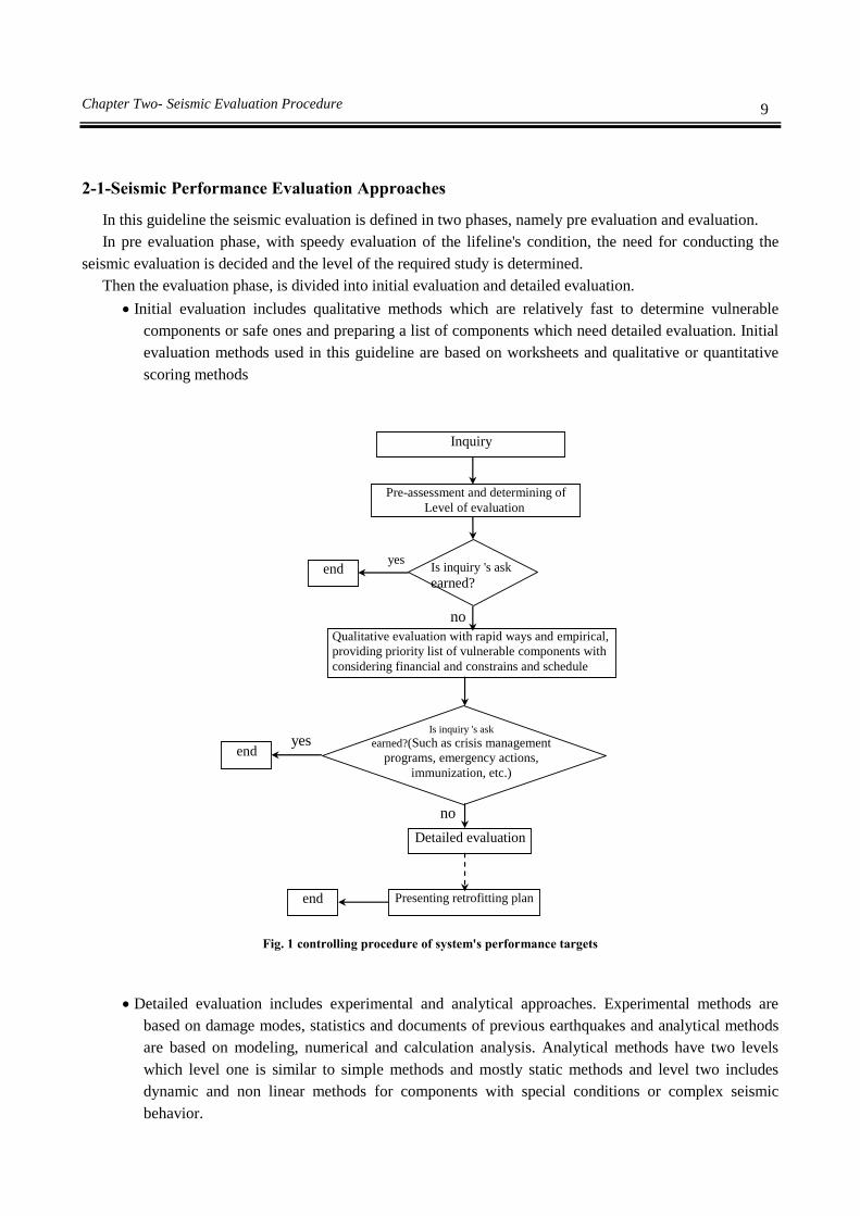
In this guideline the seismic evaluation is defined in two phases, namely pre evaluation and evaluation.
In pre evaluation phase, with speedy evaluation of the lifeline's condition, the need for conducting the
seismic evaluation is decided and the level of the required study is determined.
Then the evaluation phase, is divided into initial evaluation and detailed evaluation.
Initial evaluation includes qualitative methods which are relatively fast to determine vulnerable
components or safe ones and preparing a list of components which need detailed evaluation. Initial
evaluation methods used in this guideline are based on worksheets and qualitative or quantitative
scoring methods
yes
no
no
yes
Inquiry
Pre-assessment and determining of Level of evaluation
Is inquiry 's ask
earned?
Is inquiry 's ask
earned?(Such as crisis management
programs, emergency actions,
immunization, etc.)
Qualitative evaluation with rapid ways and empirical,
providing priority list of vulnerable components with
considering financial and constrains and schedule
end
Detailed evaluation
Presenting retrofitting plan end
end
Fig. 1 controlling procedure of system's performance targets
Detailed evaluation includes experimental and analytical approaches. Experimental methods are
based on damage modes, statistics and documents of previous earthquakes and analytical methods
are based on modeling, numerical and calculation analysis. Analytical methods have two levels
which level one is similar to simple methods and mostly static methods and level two includes
dynamic and non linear methods for components with special conditions or complex seismic
behavior.
10 Guideline for seismic evaluation and rehabilitation of Gas supply systems
2-2-Pre Evaluation
Persons in charge of gas lifeline system should always have enough knowledge about safety and proper
seismic performance of its own facilities. Otherwise they have to request for evaluation of performance of
gas facilities. Level and detail of this request depends on the knowledge of persons in charge.
Before start of evaluation, pre evaluation will be conducted by operation engineers or other persons in
charge with following goals:
Risk intensity identification and general vulnerability evaluation for this risk, in order to determine
the required volume of detailed evaluation.
Assuring that resources and necessary expertise for conducting the evaluation is available.
Determining the proper scope of work based on the request, available resources and timetable.
2-2-1-Effective Parameters in Performance Evaluation
Main parameters in a performance evaluation are:
Hazard (H)
Seismic hazard includes initial and secondary hazard. Initial hazards include ground vibration and
movements and related deformation like liquefaction, slope slide and faulting.
Secondary hazards include explosion, fire, environment pollution and similar which are caused by initial
hazards.
Vulnerability (V)
Vulnerability includes casualties, physical damages to facilities, installations and buildings, control and
operational systems, environment, commercial, financial & industrial activities, safety of installations and
investment and society and cultural heritage.
System's Performance (S)
Gas lifeline system's performance during earthquake will be evaluated and judged based on outputs, or
operational targets and or lack of safety and interruption in performance.
Important performance targets of a gas system are:
Customers and facility workers' safety
Continuity of gas flow and system's reliability
Damage prevention
Prevention of environmental damages
2-2-2-Seismic hazard identification
Initial hazards including vibration and permanent ground displacement are measured with intensity,
acceleration and ground movement.
The most common criteria for measuring vibration is peak ground acceleration (PGA) which could be
obtained from zoning maps or local investigations.
Zoning maps also could be used for hazard study of permanent deformation including, liquefaction, land
sliding and faulting which mostly are based on peak ground displacement (PGD).
Data obtained from these maps are approximate and should be used with caution. For example a region is
classified as a high risk zone for land slide only because a small part of it is located on an unstable slope.

11 Chapter Two- Seismic Evaluation Procedure
Secondary hazards like explosion, fire, environmental pollution, etc, should be studied locally and
depending on the case. Table 2-1 shows criteria used for determination of relative hazard levels.
Table 2-1 Criteria used for determination of relative hazard levels (H situation)
Seismic hazard level PGA
Low (L) 0.15g<PGA
Medium (M) 0.15g≤PGA≤0.5g
High (H) PGA>0.5g
2-2-3-Seismic Vulnerability identification
Vulnerability potential in different gas facilities varies depending on the type of seismic hazards.
Table 2-2 shows the general categorization of seismic vulnerability in three levels, high (H), Medium (M)
and low (L).
If a component or a system is located inside a building, vulnerability of that component and building
should be considered simultaneously.
For example, if a building has a collapse risk or a compulsory evacuation is necessary, then the facilities
inside that building are in risk.
Table 2-2 vulnerability degree of components due to seismic damage (V situation)
Seismic hazard
Vulnerability degree
Secu
rity, co
ntro
l and au
to
shu
toff sy
stems
Refin
eries
Hig
h p
ressure p
ipelin
es
Lo
w an
d m
ediu
m p
ressure
pip
elines
Pressu
re adju
sting
and
redu
cing statio
ns
Risers
Sto
rage tan
ks
Cen
tral office,
main
tenan
ce and
operatio
nal b
uild
ings
Seismic vibration H M L L M H H H
Ground permanent
deformation
due to earthquake
(faulting, liquefaction,
landslide)
L M H H M M M L
2-2-4-Seismic Performance
Seismic performance depends on:
Intensity and rate of hazard
Vulnerability of system or component
Consequences of damage including human loss, financial, service shot off, environmental effects and
others
Permanents redundancy of the system under evaluation( high, medium and no redundancy)
Scale of the system
In pre evaluation, performance is shown by level index IL that is defined as multiplication of H, V & S

12 Guideline for seismic evaluation and rehabilitation of Gas supply systems
IL=H × V × S or IL= H × V × max (CLS, CFL, CSD, CEI) (2-1)
Where:
H= hazard coefficient (low=1, medium=2, high=3) according to table 2-1
V= vulnerability degree (low=1, medium=2, high=3) according to table 2-2
S= system performance degree (maximum value of CLS, CFL, CSD, CEI)
CLS = life safety consequences degree, between 1-3 (table 2-3)
CFL = financial loss consequences degree, between 0.5 -6 (table 2-3)
CSD = service down consequences degree, between 0.5 -6 (table 2-3)
CEI = environmental consequences degree, between 1-3 (table 2-3)
In table 2-3 redundancy modification coefficient (Rc) is used to determine financial loss (CFL) and service
down consequences (CSD) degrees.
This modification coefficient is used to justify the decrease in consequences due to redundancy of the
system.
Redundancy modification coefficient shows the flexibility and substitution possibility under special
conditions.
For example, for a given facilities, due to lack of alternatives for serving an important customer,
redundancy coefficient might be considered 2 (without redundancy). In the same time customer might
consider the redundancy coefficient as 0.5 due to supplemental energy resources.
Service down (CSD) coefficient might vary due to nature and characteristics of the inquiry and also who
carries out the evaluation.
There are similar considerations, during the application of redundancy modification coefficient to
financial loss (CFL).
For example, for a given facilities, financial loss due to repair of a damage, might not be significant for an
industrial customer or a district which doesn't have any facilities to provide substitution energy resources.
In normal condition, redundancy coefficient is assumed one.

13 Chapter Two- Seismic Evaluation Procedure
Table 2-3 Categorizations for system performance disorder consequences (S situation)
Consequences
Intensity of consequences
Low
(normal)
Medium
(non critical)
High
(critical)
Life safety (CLS)
Lowest effects on life
safety; without any
important effect on
workers or people in the
vicinity of facilities
CLS =1
Damage or shut down
might injure workers or
people in the vicinity of
facilities CLS =2
Damage or shut down might
have significant life safety
effects on workers or people in
the vicinity of facilities
CLS =3
Financial loss (CFL) Less or low effect
CFL =Rc
Damage or gas shut off
could lead to great
financial losses but these
losses have less or low
effect on financial
integrity of facilities CFL
=2Rc
Damage or gas shut off have
great impact on financial
integrity of facilities and one
or few big and important
customers CFL =3Rc
Service down (CSD)
Less or low effect on
covered population CSD
=Rc
Gas shut off has effect
on small population (less
than 10%) and lasts for
less than one day & has
no special effect on
important & vital
customers CSD =2Rc
Gas shut off will result on:
1- Effects a significant
population (more than 10%)
2- It has potential to effect
population more than 100000
3- Will cause wide spread shut
off and lasts more than one
day.
4- Will effect performance and
operation of important & vital
facilities CSD =3Rc
Environmental
effects (CEI)
Less or low effect on
environment CEI =1
Damage or shut off may
cause limited damages
to environment CEI =2
Damage or shut off may cause
big damages to environment
(It will take months or years to
clear the effects) CEI =3
The value of RC for the system with high redundancy will be 0.5 (element damage will not decrease
system performance), and for medium redundancy will be 1.0 (element damage will decrease system
performance) and for no redundancy will be 2.0 (the element's function could not be replaced).
In approximate scoring values 1, 2 and 3 are used for low, medium and high redundancy, respectively.
Final step in scoring is the comparison of level index IL with a set of pre set limitations where they define
recommended basic levels for performance evaluation. (Table 2-4)
Based on the all possible combination of input parameters, level index could vary between 0.5 and 54.
Performance evaluation for basic level is determined with following limitations:
Basic level is used as a start point for evaluation and later it might become necessary for more complete
evaluations. Sometimes the requesting party might ask for special level of studies based on its own needs.

14 Guideline for seismic evaluation and rehabilitation of Gas supply systems
Table 2-4 Selection of evaluation levels
Level Index (IL) Basic level for performance evaluation
IL ≤6 No need for seismic evaluation
7≤IL ≤17 Usually initial evaluation is sufficient (level 1)
17≤IL ≤35 Initial & detailed evaluation with experimental and ordinary calculation (level 2)
IL ≥35 Initial & detailed evaluation with precise calculation (level 3)
2-2-6-Planning for Evaluation Study
Data necessary for seismic evaluation are different from study type obtained from levels of above
mentioned table. After determining level using below table, it is possible to determine the relevant risk level
or vulnerability level for study, using tables of this chapter.
In addition to guides of tables of this chapter, other factors like cost, timetable and inclusion of many
risks, should be considered in planning for seismic evaluation study.
Sample for recommended levels for evaluation analysis of hazard (H), vulnerability (V) and system (S)
Request item Request source Level
H V S
Request for study of general condition of the system External 1 1 1
Request from customers for study of service reliability Ditto 1 1 1
General request for total study by mass media or people Ditto 1 1 1
Collaboration with technical groups Ditto 1 1 1
Request for study of facilities in a landslide region Ditto 2 1 1
Request for study after an accident in facilities site by an authority. Ditto 1 2 1
Request for study after an accident in critical facilities Site by an authority. Ditto 2 2 2
Request for detailed hazard study of a set of
facilities by an authority.
Ditto 3 1 1
Request for detailed hazard study of
facilities by an authority.
Ditto 3 2 1
Request for determination of detailed
hazard data & criticalness by an authority
Ditto 2 1 2
Change in necessary performance level in the
new provisions
Ditto 3 3 3
Request for determination of service
shut down potential
under a local and specific hazard by an authority
Ditto
2 1 3
Request for determination of service
shut down potential
in critical facilities by an authority
Ditto
3 3 3
Request for determination of service
shut down potential
with detailed study of local hazards by an authority
Ditto
3 1 3
Request for necessary data for initial design of
facilities under different hazards Internal/external 3 1 2

15 Chapter Two- Seismic Evaluation Procedure
Request for determination of unprecedented &
huge service shut down
potential by an authority
Internal/external 3 3 2
Request of higher rank manager for study of financial
situation in case of hazard occurrence internal 1 2 1
Request for risk management or insurance Ditto 1 2 1
Investors concerns Ditto 2 2 2
Request for study of general situation
by higher rank managers
Ditto 2 2 2
Request for determination of the most critical
facilities according to hazard zoning
by higher rank managers
Ditto
1 1 3
Request for additional study and determination of
vulnerability details of critical facilities
Ditto 1 2 3
Request for determination of service of critical
facilities (like hospitals) after occurrence of hazard
Ditto 2 2 3
Request for complete study of the system under natural
disaster by manager
Ditto 3 2 3
Request for control of gas installations under
specific hazards by board of directors of gas company
Ditto 1 1 1
Table 2-5 hazard evaluation matrixes for gas system
Relevant action with hazard level of 1, 2, or 3 H3 H2 H1
1.1 Earthquake hazard- surface rupture of fault
1.1.1 Study of region's active faults maps, if they exist ♦ ♦ ♦
1.1.2 Study of topographic maps ♦ ♦ ♦
1.1.3 Study of aerial photos, if they exist ♦ ♦
1.1.4 Site survey and inspection (by an expert geologist) ♦ ♦
1.1.5 Locating active faults by excavation ♦
1.1.6 Estimating movement and displacement of faults by
experimental methods ♦ ♦
1.1.7 Determining fault displacements and their occurrence possibility
By boring holes, sampling, determining of age and analysis ♦

16 Guideline for seismic evaluation and rehabilitation of Gas supply systems
Relevant action with hazard level of 1, 2, or 3 H3 H2 H1
1.2 Earthquake hazard- liquefaction
1.2.1 Study of documents on seismicity of the region ♦ ♦ ♦
1.2.2 Probabilistic seismic hazard assessment (PSHA) ♦ ♦
1.2.3 Study of topographic maps ♦ ♦ ♦
1.2.4 Study of surface geologic maps ♦ ♦ ♦
1.2.5 Study of existing geotechnical data ♦ ♦ ♦
1.2.6 Minimum excavation and boring, standard or cone penetration tests ♦
1.2.7 Extended excavation and boring, standard or cone penetration tests ♦
1.2.8 Initial field inspection and survey (by expert geotechnical engineers) ♦ ♦
1.2.9 Identifying soils with liquefaction potential by judgment ♦ ♦ ♦
1.2.10 Identifying soils with liquefaction potential by data analysis ♦ ♦
1.2.11 Estimating lateral displacement by experimental methods ♦ ♦
1.2.12 Estimating liquefaction potential using liquefaction maps ♦ ♦
1.2.13
Detailed analysis using programs like FLAC (Fast Lagrangian
analysis of continua), estimating liquefaction probability & spread of
lateral displacements
♦
Relevant action with hazard level of 1, 2, or 3 H3 H2 H1
1.3 Earthquake hazard- strong ground motion
1.3.1 Study of documents on vibrations and seismicity of the region ♦ ♦ ♦
1.3.2 Study of seismic hazard maps of the region, if they exist ♦ ♦ ♦
1.3.3 Study of geologic maps of ground surface ♦ ♦ ♦
1.3.4 Determining factors which help for ground vibration ♦ ♦
1.3.5 Estimating levels of ground vibrations by judgment and
available maps ♦ ♦ ♦
1.3.6 Estimating levels of ground vibrations by experimental
methods ♦ ♦
1.3.7 Estimating levels of ground vibrations by analytical methods ♦
1.3.8 Execution of probabilistic seismic hazard assessment in whole
system ♦

17 Chapter Two- Seismic Evaluation Procedure
Relevant action with hazard level of 1, 2, or 3 H3 H2 H1
1.4 Earthquake hazard- landslide
1.4.1 Study of geologic maps of ground surface ♦ ♦ ♦
1.4.2 Study of topographic maps ♦ ♦ ♦
1.4.3 Study of aerial photos, if they exist ♦ ♦
1.4.4 Study of regional rainfall maps ♦ ♦ ♦
1.4.5 Site survey and inspection (by an expert geologist) ♦ ♦
1.4.6 Study of seismic maps of the region ♦ ♦ ♦
1.4.7 Landslide potential evaluation with engineering judgment ♦ ♦ ♦
1.4.8 Landslide potential evaluation using slope stability maps ♦ ♦
1.4.9 Landslide potential evaluation with experimental & statistical
analysis ♦ ♦
1.4.10 Landslide potential evaluation with analytical method ♦
Relevant action with hazard level of 1, 2, or 3 H3 H2 H2
1.5 Earthquake hazard- Tsunami
1.5.1 Locating of facilities in 20 km distance from beach ♦ ♦ ♦
1.5.2 Study of cost topographic maps ♦ ♦ ♦
1.5.3 Study of bathymetric maps in costal area (near cost) ♦ ♦
1.5.4 Study of recorded data of tidal waves ♦ ♦ ♦
1.5.5 Estimate tsunami flood potential using engineering judgment ♦ ♦ ♦
1.5.6 Estimate tsunami flood potential using judgment &
tsunami probable sources evaluation ♦ ♦
1.5.7 Flood analysis of area ♦

18 Guideline for seismic evaluation and rehabilitation of Gas supply systems
Table 2-6 Vulnerability evaluation matrixes
Relevant action with hazard level of 1. 2, or 3 V3 V2 V1
1 Pipeline vulnerability evaluation due to ground displacement
1.1 Risk evaluation for passing through areas with ground displacement
potential by engineering judgment for different levels of permanent
displacement
♦ ♦ ♦
1.2 Detailed analysis of few pipelines according to the pipe diameter,
wall thickness, displacement direction compared to pipe direction
and etc.
♦ ♦
1.3 Detailed analysis of pipeline for special site ♦ ♦
1.4 Determination of pipeline strain criteria based on available data of
pipe condition & welds and review of papers on pipes performance ♦ ♦
1.5 Determination of pipeline strain criteria using numerical models ♦ ♦
1.6 Determination of pipeline analysis acceptance criteria using
laboratory programs and finite element analysis of pipe shell ♦
1.7 Evaluation of Facilities using estimation and experimental data of
historical events (statistical) with minimum data collected at site ♦ ♦ ♦
1.8 Evaluation of facilities using site data obtained from steps 1.2 till 1.5
and precise and detailed data ♦ ♦
1.9 Facilities evaluation using actual site data obtained from steps 1.2 till
1.6 and structural analysis results of selected facilities ♦
Relevant action with hazard level of 1, 2, or 3 V3 V2 V1
2 Damage evaluation of important and critical buildings
2.1 Data collection through interview with execution managers of
facilities and building repair and maintenance workers ♦ ♦ ♦
2.2 Determine critical functioning of inside buildings and Damages
which defect or shut down these functions ♦ ♦ ♦
2.3 General inspection of site for evaluation and data collection about
general vulnerability of buildings, their content & adjacent facilities
and support
♦ ♦
2.4 General inspection of site for parallel hazard evaluation of external
resources, structures and adjacent facilities ♦ ♦
2.5 Buildings' & supporting facilities' performance evaluation by
judgment or experimental data (statistical) of past events or using
experimental evaluation of damages with minimum site data
♦ ♦ ♦
2.6 Review of architectural and structural drawings, calculations,
foundation evaluation reports & past structural evaluation to evaluate
building capacity
♦ ♦
2.7 Independent structural calculations to evaluate building capacity ♦ ♦
2.8 Computer structural analysis to evaluate building response ♦

19 Chapter Two- Seismic Evaluation Procedure
Relevant action with hazard level of 1, 2, or 3 V3 V2 V1
3 Reservoir tank evaluation
3.1 Evaluation of structural integrity of reservoir tank by engineering
judgment ♦ ♦ ♦
3.2 Evaluation of structural integrity of reservoir tank using credible
standard or reservoir equivalent design method ♦ ♦
3.3 Tank overflow evaluation due to sloshing ♦ ♦
3.4 Evaluation of effects of tank overflow on floating roofs (internal or
external) ♦ ♦
Table 2-7 Vulnerability evaluation matrixes
Relevant action with hazard level of 1, 2, or 3 S3 S2 S1
1 System performance evaluation
1.1 System maps evaluation ♦ ♦ ♦
1.2 Systems performance evaluation on natural hazards/past events ♦ ♦ ♦
1.3 Constructing system's critical model ♦ ♦
1.4 Coinciding system's model on different hazard maps (GIS) ♦ ♦
1.5 Estimation of system's performance using expert judgment
(minimum 3 cases)
♦ ♦ ♦
1.6 System analysis for limited scenarios (minimum 3 cases) ♦ ♦
1.7 Reliability and probability analysis of system ♦
Table 2-8 Necessary effort for hazard, vulnerability and performance analysis of the system in different levels
Vulnerability level 1-15 person-day work
3-10 person-week work
3-9 person-month work V3 V2 V1
H1 Hazard
level S1
Sy
stem
per
form
ance
lev
el
H2
H3
H1 Hazard
Level S2 H2
H3
H1 Hazard
level S3 H2
H3

20 Guideline for seismic evaluation and rehabilitation of Gas supply systems
2-3-Seismic Evaluation Steps
After performing pre evaluation and determining study levels, for seismic evaluation it is necessary to
clarify performance importance, vulnerability, and hazard and target performance level. These parameters
which determine volume of evaluation efforts for each element and are as follows:
1-Performance importance and total value of system
2-Seismic hazard calculation
3-Determine performance level of elements/system
4-Initial seismic evaluation
5-Initial vulnerability determination
6-Detailed seismic evaluation
7-Detailed vulnerability evaluation
2-3-1-Importance determination of element or System
The first step in seismic evaluation is to determine importance and role of system in the network which is
according to table 2-3 and is based on disorder consequences of system performance. Sub systems and
internal elements will be categorized based on their role and relative importance in gas supply system
according to table 2-9, after categorization of the systems.
Importance determination is shown in Table 2-10, according to the effects of the combination of internal
elements and whole system.
Table 2-9 Categorizations of sub systems and internal elements
Type Definition Vulnerability effect on performance
Major Has direct role in system performance Gas shut off
Supplementary Has supplementary or redundancy role in system performance Disorder in gas supply
Secondary Has not major or supplementary role in system performance unclear
Table 2-10 Determine importance with combination of internal elements and total system
Sub system or internal element
Total system Major Supplementary Secondary
High (has direct role in network performance) Very high High Medium
Medium (has supplementary or redundancy role in network performance) High Medium low
Low(does not have major or supplementary role in network performance ) Medium Low low
Obtained importance levels are defined consequently as follows:
1-Very high: Elements which their vulnerability will cause critical conditions, casualties and huge
financial losses.
2-High: Elements which their vulnerability will cause gas flow shut off, service shut down and
financial losses.
3-Medium: Elements which their vulnerability will cause disorder in gas flow.
4-Low: Elements which their vulnerability doesn't have any effect on system.
2-3-2-Seismic Hazard Levels
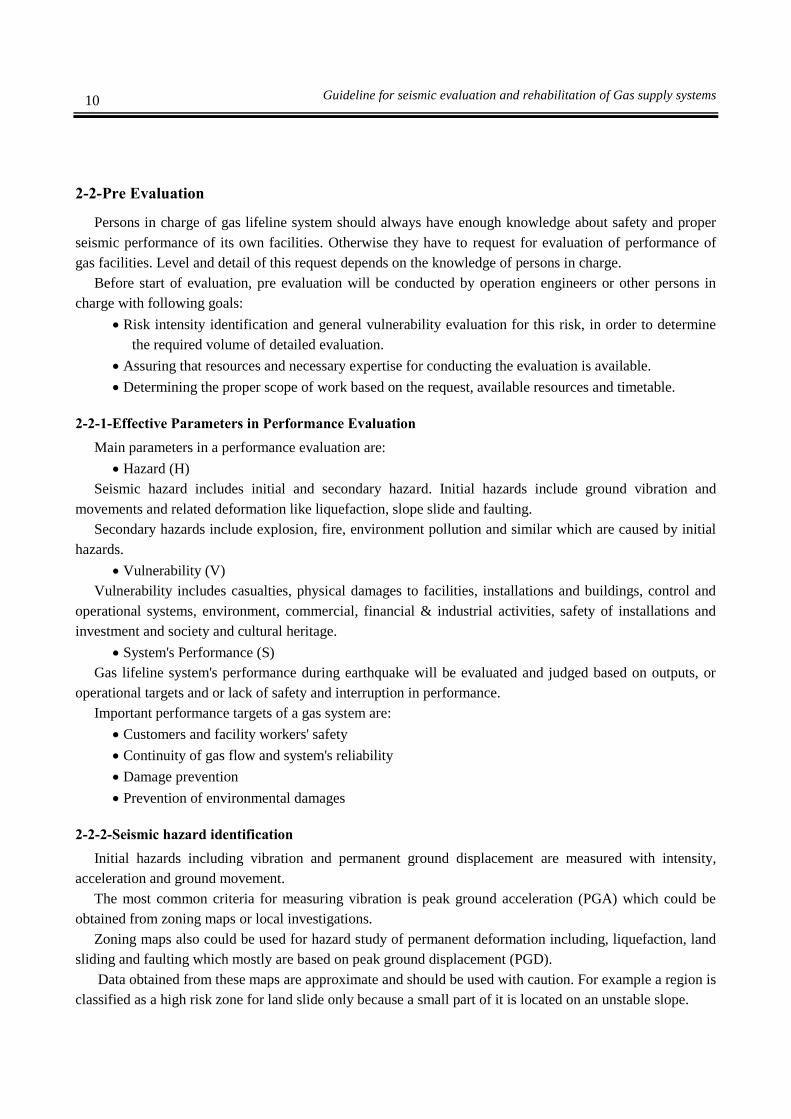
Three levels are defined for seismic evaluation of seismic hazard as follows:
21 Chapter Two- Seismic Evaluation Procedure
First level of seismic hazard: Maximum operation earthquake (MOE)
Second level of seismic hazard: Maximum design earthquake (MDE)
Third level of seismic hazard: Maximum considered earthquake (MCE)
These seismic hazard levels are equivalent to below safety levels where the precise definition for
importance degrees is given in table 2-11
Operation safety: in this level probable damages should not disrupt gas supply.
Design safety: in this level probable damages might cause temporary disruption in gas supply but
should not cause a general damage, collapse, fire, explosion, network instability and etc.
Critical safety: in this level despite high performance damages, no system performance damages
should occur and therefore it is necessary to do arrangements for reduction of secondary effects.
Table 2-11 seismic hazard level
Seismic hazard level Probability of return period in 50 years (years) Safety level
1 99.5% (75 years) Operation safety
2 10% (475 years) Design safety
3 2% (2475 years) Critical safety
2-3-3-Performance Level of System Elements
Definition of performance levels based on hazard level and importance degree of facilities is given in
table 2-12.
Table 2-12 Definition of performance levels based on seismic level and importance degree
Seismic hazard levels (performance level)
Importance 1 (Operation safety) 2 (Deign safety) 3 (Critical safety)
Very high Without any damage
and disruption in
performance
No casualties
Minor damages to facilities but still
operate
No casualties
Damages to facilities but system
operates and no critical condition
High Without any damage
and disruption in
performance
No casualties
Damages to facilities but system
operates
No casualties
Damages to facilities & probability of
temporary disruption on system
operation
Medium No casualties
Minor damages to
facilities but
continues to operate
No casualties
Damages to facilities & probability of
temporary disruption in system
operation
No casualties
Damages to facilities major disruption
in system & facilities operation but
possible to repair and restore in
acceptable time
Low No casualties
Minor damages to
facilities but system
operates
No casualties
Damages to facilities major disruption
in system & facilities operation but
possible to repair and restore in
acceptable time
Not necessary

Chapter 3
Vulnerability Evaluation
Methods


25 Chapter Three- Vulnerability Evaluation Methods
3-1-Target Components
Target components are introduced in table 3-1 of this guideline and generally are categorized to linear and
stationed components.
Looking from seismic performance point of view, this categorization is divided into single performance
of each component and systematic performance of all components of a system.
Among stationed components, for all buildings including control and logistic building and similar ones, it
should be done according to present seismic evaluation guidelines.
Table 3-1 Target components for seismic evaluation
Type Title Performance Components
Station Type
Refineries Single components
equipment
Non-Building Structures
Buildings
Non-structural elements
Systems -
Pressure Adjusting Station Single components
equipment
Non-Building Structures
Buildings
Non-structural elements
Systems -
Linear
(Network)
High Pressure
Transmission
Single components Non-Building Structures
Systems -
Low & Medium
Pressure
Distribution
Single components
equipment
Non-Building Structures
Buildings
Non-structural elements
Systems
3-2-General Approach to Determine Vulnerability
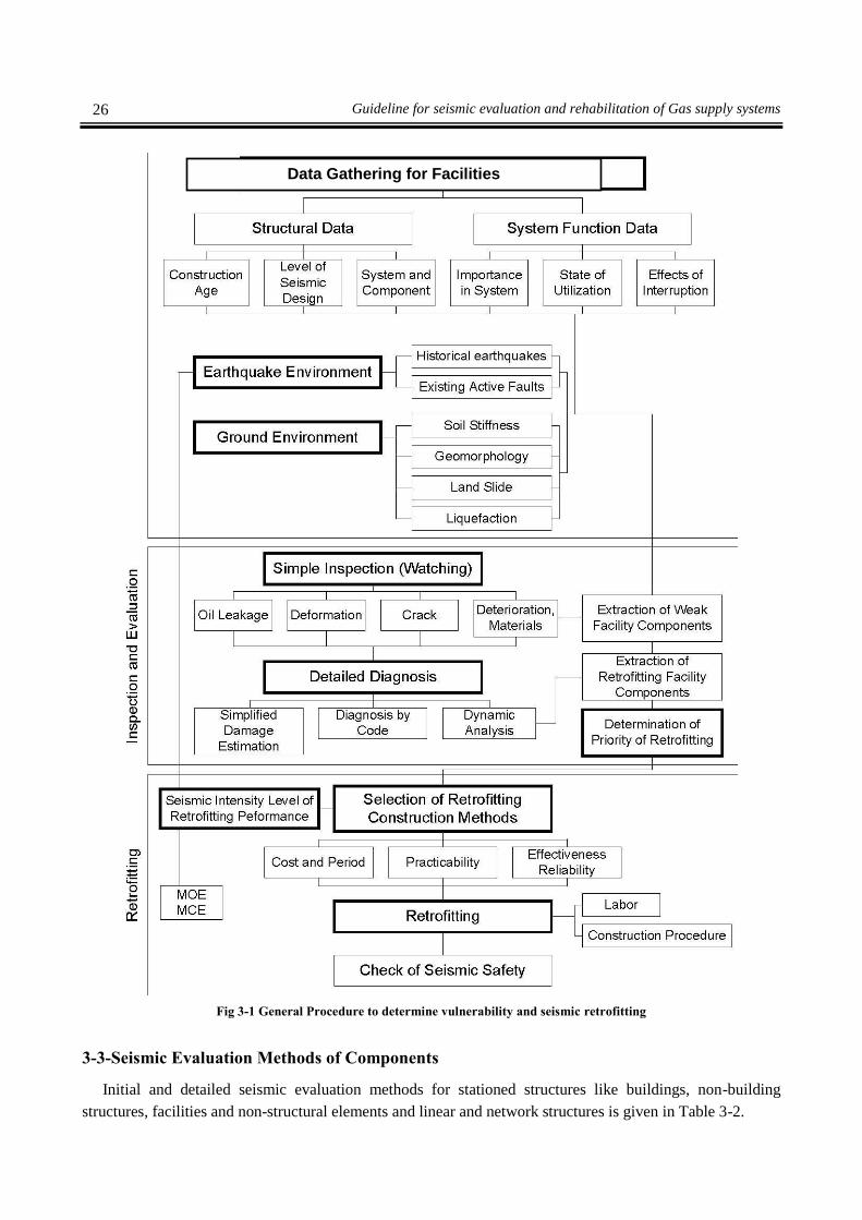
In figure 3-1, the general approach to determine vulnerability and seismic retrofitting of lifelines is
shown. This approach is divided to following four activities:
1-Data collection of structures, facilities, and equipments including data of single components and
systems from process and performance point of view
2-Review geotechnical data and seismicity of region, including soil properties and secondary problems
like landslide, liquefaction and cross faulting and study of seismic history and active faults
3-Review seismic vulnerability
4-Seismic retrofitting in case it is necessary.
26 Guideline for seismic evaluation and rehabilitation of Gas supply systems
Fig 3-1 General Procedure to determine vulnerability and seismic retrofitting
3-3-Seismic Evaluation Methods of Components
Initial and detailed seismic evaluation methods for stationed structures like buildings, non-building
structures, facilities and non-structural elements and linear and network structures is given in Table 3-2.
Data Gathering for Facilities

27 Chapter Three- Vulnerability Evaluation Methods
Table 3-2 Seismic Evaluation Methods of Components in Different levels According to Chapter 2
Component Assessment
Methods Level 1 Assessment Methods Level 2 Assessment Methods Level 3
Building Structures Rapid assessment Rapid assessment Detailed assessment
Non-Building
Structures
Qualitative
assessment
worksheet and
scoring method
Seismic behavior control by
reviewing design documents and
using simple and equal static code
methods
Analyze of dynamic and
interaction behavior by
analytical and numerical
modeling
Equipment
Qualitative
assessment
worksheet and
scoring method
Seismic general stability control by
reviewing design documents and
using simple and equal static code
methods or empirical methods based
on failure curves
Analyze of dynamic and
interaction behavior by
analytical and numerical
modeling
Non-structural
Elements and Building
Internal Equipment
Qualitative
assessment
worksheet Qualitative assessment worksheet
General stability control using
simple and equal static or
empirical methods
Above and
Underground, High and
Low Pressure
Transmission and
Collection Pipelines
Qualitative
assessment
worksheet and
scoring method
Seismic general stability control
under geotechnical hazards (sliding,
faulting, liquefaction, …) and nearby
structure impact by reviewing design
documents and using simple and
empirical methods
Analyze of dynamic behavior
under geotechnical hazards
(sliding, faulting, liquefaction,
…) and nearby structure impact
by analytical and numerical
modeling
3-3-1- Seismic Evaluation of Buildings
Key issues on evaluation of functionality of buildings are as follows:
Economical value of the structure and remaining years of operation life
Building's functionality including number of residents under threat inside structure and those
structural damages, which could release dangerous materials and make casualties outside the
structure
Structure's functionality and economical & social consequences if there is damage to its service
due to earthquake
Historical importance of the structure and effects of seismic retrofitting to historical and cultural
resources
Seismic risk of the site
Comparison of retrofitting cost to its obtained benefit
Initial seismic evaluation or level one for steel and reinforced concrete buildings will carry out according
to instruction number 364 of President Deputy Strategic Planning and Control (PDSPC). The title of this
instruction is "Fast Visual Evaluation Method for Steel and Reinforced Concrete Buildings" and for masonry
buildings the "Fast Qualitative Evaluation Method" which is given in chapter 3 of instruction number 376 of
the above-mentioned organization, will be used.
Detailed assessment in the level 3 of concrete and metal buildings will be done using term of reference in
publication No. 251 as the title of term of reference for seismic retrofitting of existing buildings and

28 Guideline for seismic evaluation and rehabilitation of Gas supply systems
Instruction No.360 from President deputy strategic planning and control as the title of instruction for seismic
retrofitting of existing Buildings.
Detailed assessment of existing masonry buildings will be done using instruction for vulnerability
analysis and seismic retrofitting of existing unreinforced masonry buildings (building undersecretary of
ministry of housing and urban development).
3-3-2-Seismic Evaluation of Non-Building Structures
Initial evaluation of non-building structures will be carried out in components and it will be as follows:
Study of seismic design documents with emphasis on structures as-built conditions if there is any
Site investigation, preparation and utilizing seismic worksheets with emphasis on structure type
and qualitative scoring
Utilizing simple and static equivalent code method and control of general seismic stability
In the initial evaluation of non-building structures, usually system's study will not carry out.
If in this stage, the components are vulnerable, then the detailed evaluation of components and whole
system will be done.
Detailed evaluation of non-building structures will be done by modeling and numerical analysis. This
study includes dynamic behavior and structural interaction analysis.
Utilizing detailed method for complex structures or those with indeterminate dynamic behavior or with
considerable interaction with surrounding environment and other structures is necessary.
3-3-3-Equipments' Seismic Evaluation
Seismic evaluation of equipment will be carried out as follows:
Study of seismic control documents with emphasis on installation condition including seismic
tests documents and performance control by its maker.
Quantitative scoring method.
Simple and equivalent static code method and control of general seismic stability.
In the initial evaluation of equipment, usually system's study will not be carried out.
In case, in this stage the components are vulnerable then the detailed evaluation of components and whole
system will be done.
Detailed evaluation of equipment will be done by modeling and numerical analysis. This study includes
dynamic behavior and structural interaction analysis.
Utilizing detailed method for complex structures or those with indeterminate dynamic behavior or with
considerable interaction with surrounding environment and other structures and facilities is necessary.
3-3-4-Seismic Evaluation of Non-Structural Elements
Seismic evaluation of architectural and internal elements of buildings like walls, racks and false ceiling
and internal installments like plumbing and canals will be done in one-step and will be done using following
guidelines and instructions:
Seismic retrofitting of buildings publication number 360
Seismic design of gas lifeline instruction
Seismic retrofitting of oil installments guideline
Seismic assessment of power plant, publication number 360
Other authoritative references, which are introduced in this guideline

29 Chapter Three- Vulnerability Evaluation Methods
3-3-5- Seismic Evaluation of Network and Pipelines
Initial evaluation of network and lines are done as follows:
Study of seismic design documents of network, if there is any
Preparation and utilizing seismic worksheets with emphasis to network type and qualitative
scoring
Simple and equivalent static code method and control of general seismic stability
Utilizing damage curves of components and general vulnerability determination of network using
combinatorial formulation based on reliability (see appendix 2)
Detailed evaluation of network and lines is done as follows:
Seismic vulnerability numerical analysis of components
Determination of general vulnerability of the network using combinatorial formulation based on
reliability
Seismic evaluation of structures in the vicinity of distribution network should be done on a case-by case
base according to relevant instructions (publication number 360 and 364 of PDSPC for steel or reinforced
concrete buildings and publication number 376 for masonry material buildings) and quantitative methods
should be used as much as possible. If quantitative evaluation methods are not possible, qualitative
evaluation methods should be used according to relevant instructions. For very important components of the
network, quantitative evaluation of structures on the close vicinity is necessary.
3-4-Inspection and Filling Worksheets in Level One Qualitative Evaluation
Site inspection usually will be done by a qualified engineer or a team of engineers. This method should be
done in a determined manner and systematically so that the continuity and completeness of work is achieved.
Usually the steps are as follows:
Meeting with clients, technicians, persons in charge of standards and safety engineers or other
beneficiaries in order to discuss about the goals of inspection and getting the necessary facilities
for the team.
Identification of equipments, structures and other desired components. If review has been done as
part of risk analysis or safety analysis, engineers in charge of site investigation should reconsider
the assumptions used in risk analysis for probable future earthquake in critical systems.
For purposes like insurance evaluation or determining total risk, if the review is optional, then
evaluating engineers should visit major equipments and structures.
Categorizing vulnerability modes.
Collection of local data like seismic risk, fault location, opening in the soil.
Systematic site inspection of components using worksheet for each section so that evaluation is
documented and rules are reminded.
Review of drawings when it is necessary to control adequacy of reinforced concrete, determining
anchorage detail or diagnose and determine necessity of issues like fire proof coverings, isolations
and etc. where the visual inspection is not possible.
Review analysis for elements with critical conditions or any sections which seems to have seismic
risk. These risks include risk of release of poisonous materials, pollution or any unacceptable
performance like disruption in economy and trade.

30 Guideline for seismic evaluation and rehabilitation of Gas supply systems
Documentation of weak and suspicious cases for clients and persons in charge of standards
including adequate explanation like retrofitting of operations, storage of extra evaluation and etc.
should be carried out.
Structural and mechanical recommendations which might decrease the above mentioned risks.
Engineer should consult with process and safety engineer and managers for economical evaluation
and possibility of execution of retrofitting solutions.
Prioritizing of recommended risk reduction activities should be done based on consequences of
risk evaluation.
In practice, teams should walk along the line and inspect the major components. For example, each
component should be inspected for cases like leakage of dangerous materials, possibility of fire and reaction
with other materials and explosion or collapse.
Most of these inspections should be carried out independent from initial risk analysis.
It is recommended that site inspection teams have interaction with risk analysis teams.
Seismic evaluation teams including safety engineers should be able to explain probable earthquake effects
on facilities to clients. For example:
All facilities will vibrate simultaneously without warning.
Vibration may take 10 seconds or more. In very large earthquakes (larger than 8) vibration lasts
for about 60 seconds.
Possibility of dismissing reserve gas.
It is probable that many systems like telephone, water and … damage simultaneously and for long
time.
It is probable that buried pipes broke.
Vulnerable elements of specific equipments and piping system may stop working.
Essential services located out of region might be unavailable due to occurred problems in lifelines
(like bridges and highways) or extra ordinary operation.
Safety of operators or families is prior to safety of equipments so it is not recommended to use
operators to decrease damages.
Site inspector should be in close contact with operators, client, safety engineers and other officials of the
project.
For example, a civil engineer knows great problem in connection with carrying dangerous pipes.
But must be underlined that every potential damage needs to decrease.
More important factors in hazard Prioritizing include consideration such as continues operation or how to
preserve generation.
During a destructive earthquake there is the possibility that facilities outside the site are destroyed for
long time.
In this case, it seems necessary to prepare a reserve gas and water reservoir.
Local inspection team must identify other effective urgency systems in system operation in order decrease
earthquake effect is considered.
In this regard the need for alarming system and fire extinction system, telecommunication system and
deterrent system for better operation after the earthquake should be emphasized.

31 Chapter Three- Vulnerability Evaluation Methods
Major technical consideration points during inspection include:
Earthquake risk level: In regions with low seismic risk, big buildings and vessels that designed for
wind load nonetheless, might damage cause of ground motion.
Intensity of Geotechnical risks (faulting, ground failure and land sliding): Inspecting team should
be careful about probable damages to buried pipes and equipments, which are based on different
structural system due to geotechnical risks near the site. If fault is crossing from the site,
evaluation should include additional geotechnical investigations.
Applicable standards during the construction phase: Applicable standards and seismic design
methods might change comparing to initial design time.
Evaluation of total capacity of new equipments should be emphasized. In the evaluation of older
equipments, damages like deformation damaged concrete, steel corrosion and etc should be
emphasized.
If the overall quality of repair and maintenance is not suitable, site-inspecting team should
evaluate number of lost bolts and nuts, non-repaired damages, site modifying & changes
especially in the first inspection and the same is valid for connection.
Process safety engineers and clients should be informed and assured about the initial evaluation of
safety, pollution or economical consequences of damages through the site inspectors.
Site inspectors should be careful about the regions vulnerable to corrosion. This is not that much
related to surface corrosion but includes cases like structural strength reduction due to decrease in
thickness, holing or layering. Regions where there are corrosion materials like acids or places with
accumulated water are vulnerable to corrosion.
Another region where corrosion might be a problem is where the concrete cover has peeled off
and rears are exposed to environment. These regions are considered as a restoration case. As
cracking is considered as one of the concerned cases with high priority in facilities, inspecting
teams might help in finding these areas.
During the simple inspection, engineers could also evaluate installed facilities which have
problems. These problems might be seen in welds or bolts. For example extension anchorages
might not have sufficient length and could not act up to their designed tensioned capacity.
Seismic interaction occurs when there is no sufficient gap between two units to prevent collision.
This might occur due to slide of unanchored facilities; sway of suspension pipes, cable racks, and
electrical boxes hit each other, walls or other structural elements.
Unsymmetrical displacements usually causes damages to facilities fixed to structural systems.
Engineers should be aware of conditions where installments like pipes, ducts and etc should have
sufficient flexibility for movement. Flexibility is a key characteristic against decreasing damage to
facilities.
Another concern is water sprinkle systems where it might affect the electrical facilities. Fire
extinguisher pipe (used for earthquake caused fire) might affect electrical facilities.
Other structures in the vicinity of distribution network might collide with network components and
cause damage. This vulnerability might be evaluated. First those structures which are close enough
to the network which upon complete are partial collapse might collide with network components
should be identified. Then these structures must go under seismic evaluation.
Seismic assessment adjacent building of distribution network

32 Guideline for seismic evaluation and rehabilitation of Gas supply systems
Demanded operational level in assessment of this building, for design hazard level according to
related procedures must be equal to Threshold collapse and for component with high importance is
considered safe life.
If it is n't possible to assess the quantitative evaluation for Gas lifeline components' evaluation
could be done using recommendations, worksheets and retrofitting & evaluation guidelines used
for petroleum facilities.
3-5-Collection of Necessary Data for Evaluation in Level 2 and Level 3
Collection of necessary data for quantitative evaluation should be done with in a planned manner.
Resources for determining and collecting the necessary data are as follows:
Present documents in different phase of design, operation and periodic maintenance: These
documents should be compared with present status of the network and they should be updated if
necessary.
Inspection and data collection with visual and measurements methods: For this purpose if it
becomes necessary, sample core should be taken and top layers and covers should be taken
(without disrupting the performance or behavior of the component) and requested parameters and
data are measured.
Conducting the necessary tests: If data couldn't be obtained from documents or present catalogues
and it become necessary, then tests should be conducted. The most important tests are those used
to obtain soil type, characteristics and mechanical properties of material. In general non
destructive test are preferable. If it becomes necessary to conduct a test on connecting equipments
like bolts or insulators and similar, at least the test piece should be substituted with similar sample.
In any case during coring or test, damage or weakening on any elements of the network should be
prevented.
3-5-1-Design and Operation Documents' Collection
In the beginning of seismic evaluation study, structural documents of facilities including buildings, non
building structures and equipments should be collected as much as possible and reviewed thoroughly.
Workshop drawings should be conformed to the executed ones and updated if there are big
inconsistencies. Data collection related to changes and probable repairs and influential accidents on behavior
of facilities is necessary.
Reports of soil mechanic and material tests and also risk analysis studies should be collected as much as
possible and checked.
3-5-2-Visual Inspection and Extraction of Evident and Obvious Problems
In this stage of data collection, study and review is done in order to find evident and obvious problems
where they cause clear weakness in the seismic behavior of facilities.
Comparison of shop drawings, as-build and installation drawings with present status of facilities is
necessary in this stage.
3-5-3-Conducting Soil Mechanics and Material Test and Risk Analysis
This stage of data collection should be done if according to consulting engineers' judgment, the above
mentioned data collection is not sufficient for initial or detailed evaluation. Client's approval is compulsory.

33 Chapter Three- Vulnerability Evaluation Methods
Table 3-3 shows the conditions where the soil mechanics and material test are necessary and shows the
content of these tests too.
Standard and general test definitions for buildings are according to the "seismic retrofitting and
evaluation of present buildings instruction" (publication number 360). For non building structures and
facilities, there is no given set of tests and contents of tests should be given by consultant engineer and
client's approval.
Table 3-3 Soil Mechanics and Material Tests
Comparative Importance
of the System
Soil and Material
Data
Level of
Tests
Very High available Standard
Not available Complete
High available -
Not available Standard
Medium available -
Not available Standard
Low available -
Not available -
3-6-Seismic Evaluation Using Modeling and Numerical Analysis
Modeling and analysis methods are based on determination and comparison of seismic need-capacity of
facilities, structures and their connections.
Modeling and numerical analysis include following two major aspects:
Suitable modeling based on dynamic and mechanical specifications.
Seismic loading and numerical analysis based on the model. Loading details are according to
"power systems seismic design instruction"
Following numerical analysis methods for structures are recommended:
Equivalent static method
Spectrum method
Time history method
3-6-1-Equivalent Static Method
For seismic analysis of facilities where the first vibration mode is the dominant mode, the equivalent
static method is recommended according to non building structural section of standard 2800.
For facilities with natural period less than 0.03 seconds it is acceptable to multiply maximum floor
acceleration to the elements' mass and apply this force into the mass center of the element without need for
intensification factor.
3-6-2- Spectral Method
In complex facilities where vibration modes are apart from each other, it is recommended to use spectral
analysis method according to the non building structural section of 2800 standard.

34 Guideline for seismic evaluation and rehabilitation of Gas supply systems
3-6-3-Time History Method
For seismic evaluation of complex facilities with vibration modes close to each other where their numbers
do not have big differences with each other, it is recommended to use time history method according to non
building structural section of 2800 standard to control the results obtained from spectral method.
3-7-Seismic Interaction of Systems
Seismic interaction of systems is a collection of effects on seismic behavior and intensification of earthquake
effects including undesired changes in dynamic characteristics due to structural interaction, collision of
adjacent systems, collapse of systems on each other, relative displacement of adjacent systems and changes
in environmental and operational conditions which will alter operation of systems or damage the operators.
Usual causes of interaction could be categorized as follows:
1-Adjacency: Any effects resulting on malfunction of system due to adjacency of systems including
collision, relative displacement and structural interaction
2-Rupture and collapse: Any effects resulting on malfunction of system due to failure, rupture and
collapse
3-Sprinkles: Effects due to rupture of pipes or malfunction of fire sprinkles, which might cause short
circuit or power plants units become out of reach.
4-Flooding: Effects due to flooding and submergence of systems and becoming inaccessible
5-Fire: Effects due to fire including smoke distribution, destruction of systems
Each system, which is under the negative effects of above-mentioned interactions, is called "interaction
target" and those systems, which their malfunction is the cause of interaction is called "interaction source"
Those interactions, which cause failure or malfunction of the system, are called "considerable
interactions" and if the effects are negligible then it is called "non considerable interaction".
Evaluation of effects of seismic interaction in "interaction target" could be done with one of the following
4 methods:
1-Ignoring the effects of interaction (non considerable interaction)
2-Modifying of "interaction source" in order to eliminate interaction effects (considerable interaction)
3-Increase the relative importance of "source interaction" up to target interaction systems
(considerable interaction)
4- Improving suitable performance for facilities of "target interaction" in scoring method (considerable
interaction) unless facilities of "source interaction" (by assuming relative importance) will be
evaluated equally as facilities of "target interaction" (approach number 3).
3-8-Acceptance Criteria
Facilities will be vulnerable when the sum of seismic load combination and other applicable loads will
exceed the seismic capacity of the elements. Seismic capacity of elements will be calculated based on
seismic design guidelines.
3-8-1-Load Combinations
Load combinations for vulnerability evaluation of non building components are as follows:

35 Chapter Three- Vulnerability Evaluation Methods
Dead Loads + Service Live Loads + Horizontal component of Earthquake (in two independent directions)
+ Vertical component of Earthquake (in two independent directions)
In above load combination, in seismic design level, earthquake loads (horizontal and vertical) should be
multiplied by 1.4.
3-8-2-Stability Controls
In non anchored components, in addition to strength needs and seismic capacity, toppling, sliding and
displacement controls also should be done.
Safety factor for sliding is the ratio of passive loads to active loads in two crossing independent
directions. Safety factor for toppling is the ratio of passive moments to active moments in two crossing
independent directions.
Unanchored elements and facilities should not be controlled for toppling and sliding against seismic
loads. Minimum safety factors for toppling and sliding in both risk levels are 1.75 and 1.5 respectively.
3-8-3-Acceptance Criteria in Non Linear Dynamic Methods
Generally in non linear dynamic methods, evaluation and acceptance is based on criteria which are
combination of load and displacement.
In gas distribution networks, according to facilities and network operation, if non linear analysis is done
then stresses and internal forces in non deformable components (controlled with force) should be controlled
in the same way as it is done in linear methods (which is given in previous sections).
In deformable components which enter non linear area, displacements and rotations should be in a level
not to interrupt the operation of the component under consideration.
Decision on this issue should be done based on technical specifications of facilities and judgment of
experts.
Chapter 4
Seismic retrofitting methods and
procedures


39 Chapter Four- Seismic retrofitting methods and procedures
4-1-Prioritizing retrofitting activities
Prioritizing retrofitting activities will be done according to following indices:
Level index IL
Change of performance level
Retrofitting cost
Ease of execution of retrofitting method
The general method for prioritizing retrofitting activities is based on risk analysis.
To do this analysis, it is necessary to determine what will happen if retrofitting activities are not done and
it will be decided based on the result of this vulnerability study.
Consequences of abolishing retrofitting will be considered in five categories namely, casualties,
possibility of social or political unrest due to time of flow shut off, direct financial losses to facilities,
economical losses due to shut down of lifelines and environmental damages. These criteria will determine
general safety of the structure or facility.
The highest priorities are the first two categories. In other categories by comparing retrofitting cost and
estimated damage losses, the risk of un-retrofitting will be determined and then it will judged.
In risk analysis damage modes and different retrofitting levels also could be compared.
4-2-Seismic retrofitting procedure
Seismic retrofitting procedure for structures and facilities is a try & error one and when structures'
vulnerability is found then it will be done as follows:
1-Selection of retrofitting methods based on damage modes of structures & facilities and their
performance.
2-The findings of retrofitting methods should be implemented on structural model and vulnerability
should be checked again until the required performance is obtained.
3-Comparison of acceptable retrofitting methods based on cost, time and ease of execution indices
through value engineering and prioritizing retrofitting methods of structures and facilities.
4-Categorizing seismic retrofitting of elements of the system based on clause 4-1
4-3-Retrofitting selection method approach
Seismic damage reduction methods for structures and facilities could be categorized into two general
categories as follows:
Hardware methods in shape of retrofitting, correction or in final shape renewal
Software methods in shape of change in operation plan, change in performance level and increase of
safety and reduction of possibility of occurrence of secondary disasters
Retrofitting method depends on the dominant failure mode of facility. Therefore selection of proper
retrofitting methods is directly related to credibility of results of vulnerability evaluation. In these studies
failure mode and amount of damage should be determined clearly.
Depending on hazard level, failure mode could be different and this issue should be considered in
selection of retrofitting method so that all probable failure modes could be controlled by suitable retrofitting.

40 Guideline for seismic evaluation and rehabilitation of Gas supply systems
In the study of failure modes and presenting retrofitting methods all initial and secondary failure modes
should be considered. Secondary failure modes include ground permanent displacements, fire, explosion,
interaction and collision of structures and collapse of debris and other cases.
4-4-Type of retrofitting method
In next chapters, seismic retrofitting methods of structures and gas supply system will be presented
according to seismic vulnerability modes in four sector namely, refinery, tanks, transmission and distribution
pipelines and other related structures.

Chapter 5
Seismic Retrofitting Methods for
Refineries


43 Chapter Five- Seismic Retrofitting Methods for Refineries
5-Refinery
The target components in a refinery in this guideline are as follows:
Piping and pipelines rack: Pipelines are divided into different categories namely tank piping, process
piping, on-ground/ under-ground piping and facilities' piping.
Horizontal tank: This guideline could be used for seismic design of horizontal tank (with storage
capacity of 3t or 3000 m3 or more)
Tower and vertical tank: Includes tower (In high pressure gas facilities tower are reaction,
separation, purification, condensing units and etc which has length equal to or more than 5m),
condenser (vertical cylinder type with body length equal to or more than 5m) and vertical tank
(with storage capacity of 3t or 3000 m3 or more)
Spherical tank: This guideline could be used for seismic design of spherical tank (with storage
capacity of 3t or 3000 m3 or more)
5-1-Piping and pipe supporting rack
5-1-1-Damage modes
Piping system of gas refinery and petrochemical factories will damage a lot during an earthquake. Pipe
damage is divided into piping system damage and supporting structure damage. Damages usually are divided
into damage to pipe element (pipe and supports) and piping system due to inertia force induced by relative
displacement and ground movement.
1-seismic damage to piping system
a) Seismic damage of pipe and pipe support
i) Seismic damage of pipe
1-Cracking and butt type weld break
This occurs when the weld is defective or weld strength is less than main pipe strength
and effect of decrease of bending moment in knee is not forecasted. If surface defects
exist like cracks along thickness or weld incomplete penetration in low temperature,
brittle break in low temperature may occur as well.
2-Loosened flange connection
This occurs when the leakage start moment in flange is less than steel pipe yield moment
and bending moment reduction in knee is not expected.
3-Crack, yield and pullout of bolts in piping facilities
Plastic deformation only in bolt section is developing because bolt root is small in
threaded part.
4-Pipe wall crack on weld surface in pipe support
In main piping of furnace or in long, high diameter and thin thickness pipes and etc, if
displacement due to heat expansion of pipe is restrained in longitudinal direction of pipe
in one point, this kind of crack will show itself in the welding point of support to pipe
wall.
5-Cracks in PVC pipes

44 Guideline for seismic evaluation and rehabilitation of Gas supply systems
PVC pipes have less deformability comparing to steel and plastic deformation in knee
should not occur. Deformability of these pipes will diminish in rapid strains and they are
weak in impact as well.
6-Crack in cast iron manhole
Cast iron manhole is made from brittle material. Most of the failures are due to inability
to absorb energy or low bending moment capacity of pipes because their relative
stiffness is weak.
ii) Seismic damage to support structure of pipe
Following cases have been reported after damage occurred in pipes which do not lead to
leakage:
1-Pipe vibrates and pipe span elongates due to support failure because of low strength
2-Pipe vibrates and pipe damages due to improper function of support due to its age.
3-Pipe damages due to relative displacement of facilities on both sides of pipe
4- Pipe damage due to relative displacement between tower and supporter because of
failure of tower stabilizer which is connected to supporter. Bending of stabilizer's
support will absorb much of the earthquake energy and less energy will transfer to pipe.
An energy absorber support is a method to overcome this problem. Big deformation of
support due to relative displacement of ground will decrease its effect on pipe.
b) seismic damage in piping system
Seismic damage in piping system is due to inertia force and ground displacement.
i) Seismic damage due to inertia force and ground displacement
Most of the damages are due relative displacement and secondary disasters caused by
vibration and pipeline displacement.
1- Pipeline failure due to relative displacement between tower and adjacent frame structure.
(support response displacement)
2-Pipeline failure due to relative displacement between tower and frame structure caused by
support beam vibration (support response displacement)
3-Break of small pipes due to relative displacement caused by vibration of big diameter
pipes. (pipeline response displacement)
Figure 5-1 Damages in pipes with small diameter

45 Chapter Five- Seismic Retrofitting Methods for Refineries
4-Pipe fall down from support (pipe slide)
5-Release from support spacer (pipe slip)
6-Failure in pipeline facilities due to displacements caused by high vibrations of shutdown
of emergency valve
7-Failure of connected pipelines and failure of generator due to relative displacement
caused by generator movement above separator desk (slip of support structure)
Following damages are also probable although they are not confirmed.
8-Pipe fall down due to separation of suspended connecting fixtures (pipe response
displacement)
9-Pipeline failure due to relative displacement caused by cylindrical tank uplift force
Figure 5-2 Pipe separation from support due to acceleration response
Cooling of pipe due to stop of work, will cause pipe to contract and could lead to pipeline
break.
If pipe fall down is due to support vibration and structural issues like stabilizers are
considered, most of damages should be prevented seriously.
ii) Damages due to ground relative displacement
Following cases are reported due to ground movement. Relative displacement due to
liquefaction is a unilateral loading which does not cause fatigue. But if earthquake force is
big like Hyogoken Nanbu Earthquake, it will cause serious damages.
1-Damage due to relative displacement caused by pump & tank settlement sit on spread
foundation.
2- Damage due to relative displacement caused by settlement and vibration around tank
with pile foundation.
3- Crack in nozzle of cast iron pump, crack of sheath and axial misalignment due to
movement and settlement of pump with independent foundation.
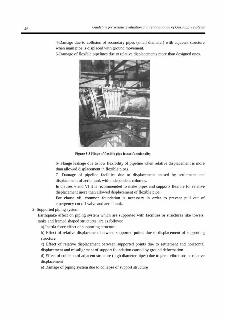
46 Guideline for seismic evaluation and rehabilitation of Gas supply systems
4-Damage due to collision of secondary pipes (small diameter) with adjacent structure
when main pipe is displaced with ground movement.
5-Damage of flexible pipelines due to relative displacements more than designed ones.
Figure 5-3 Hinge of flexible pipe looses functionality
6- Flange leakage due to low flexibility of pipeline when relative displacement is more
than allowed displacement in flexible pipes.
7- Damage of pipeline facilities due to displacement caused by settlement and
displacement of aerial tank with independent columns.
In clauses v and VI it is recommended to make pipes and supports flexible for relative
displacement more than allowed displacement of flexible pipe.
For clause vii, common foundation is necessary in order to prevent pull out of
emergency cut off valve and aerial tank.
2- Supported piping system
Earthquake effect on piping system which are supported with facilities or structures like towers,
tanks and framed shaped structures, are as follows:
a) Inertia force effect of supporting structure
b) Effect of relative displacement between supported points due to displacement of supporting
structure
c) Effect of relative displacement between supported points due to settlement and horizontal
displacement and misalignment of support foundation caused by ground deformation
d) Effect of collision of adjacent structure (high diameter pipes) due to great vibrations or relative
displacement
e) Damage of piping system due to collapse of support structure

47 Chapter Five- Seismic Retrofitting Methods for Refineries
Figure 5-4 Damage to piping system due to damage to building
f) Damage to piping system due to collapse of adjacent structures
g) Damage to free fall of masses from top
Clauses ii and iii are due to relative displacement but loading of clause ii is cyclic and
loading of article iii is continuous and single sided.
High diameter pipes of supporting structure are small pipes junction from itself.
3- Structural consideration in seismic design of piping system
Dynamic characteristics of facilities or structures in earthquake are affected by their
configuration. Damage mode of piping system supported by facilities is in fact the damage mode
of supporting structures.
Table 5-1 shows issues on types of piping system.

48 Guideline for seismic evaluation and rehabilitation of Gas supply systems
Table 5-1 Issues on types of structures in seismic design of piping system
Piping system type Seismic design points
Tank piping
Around tank floor with low
temperature Prevention of contraction of heat nozzle, settlement
Around the tank with dangerous
materials Ground and tank settlement
Perimeter of spherical tank Vibration and settlement of spherical shell
Perimeter of horizontal vessel Settlement
On ground
piping and connected
to structure
Tower perimeter High vibration of tower tip
Tower perimeter with supporting
structure Relative displacement between tower & structure frame
Piping of furnace and boiler Prevention of heat nozzle contraction
Compressor perimeter Releasing pipe reaction
Pump perimeter Foundation settlement
Heat exchanger perimeter Relative displacement
Air cooling fans perimeter Prevention of heat nozzle contraction
Over pipe supporting (rack)
structure Slide and fall down of piping
On ground &
underground
piping
Underground piping Settlement and ground displacement
Inside manhole piping Manhole floor uplift force
Piping near quay quay movement
Water channel with high
diameter Axial slide control
Piping attachments
Emergency shut off valve
perimeter
Relative displacement (vibration of upper part &
independent pier movement)
Air tank perimeter Relative displacement (independent pier movement)
In addition to inertia forces, tank pipes are sensitive and vulnerable to relative displacement
between tank and ground and process pipes are vulnerable to relative displacement between
facilities, structures and pipes.
On ground and underground pipes are influenced by ground movement and pipes attachments
and facilities are vulnerable to displacements between pipes, facilities and structures including
fast emergency shutoff valve.
Liquefaction is effective on all pipes and its effect is stronger in near coastal areas.
Categorization of weak points or damage status is possible through investigation of pipeline and
attached facilities' performance.
In general, the vulnerable points and modes are as follows:
Flange connection
Flexible pipe and connection
Valves
Pump
Pipe branches and curved pipes
Pipe system on the supporting structure
Threaded connection

49 Chapter Five- Seismic Retrofitting Methods for Refineries
Touch and collision of pipes and structures adjacent to each other
Pipes with small cross section
Pipe in the vicinity of entering a wall
Collapse of pipe supporting structure
Damage modes are as follows:
a) Flange connection
Seismic forces will loosen the flange connections and poisonous and flammable contents
will leak and cause serious damages.
To prevent connection displacement (which is caused by bending moment), special
arrangements is necessary.
b) Flexible pipe and connection
With proper use of pipes and connections, it is possible to absorb earthquake's force and
displacement. Nevertheless, when lateral displacement increases flexible pipes are unable
to absorb these forces, and this condition damages pipeline and its supporting structures.
c) Valves
Even if valves are built from steel, stress concentration in points will cause crack and cause
valve leakage. Bending moments are concentrated in areas where pipes and plate valve
stiffness are different and could cause problems.
d) Pump
When pumps faces pipes, weak areas will form in the connection area of pipe and pump
and this could cause problems to pump.
Bending moments will cause stress concentration in areas where there is stiffness difference
between pump and pipe.
e) Pipe branches and curved pipes
Bending moments will cause stress concentration due to different shape and sizes in
branches and curved pipes in comparison to other pipes. This will cause pipes to rupture.
Cast iron pipes will damage more. Steel pipes are not immune from damage.
f) Threaded connections
High stiffness in threaded connections (knee and branches) will cause damages in straight
pats of pipes and straight pipes and mechanical connections will cut out with tension force.
g) Touch and collision of pipes and structures adjacent to each other
Independent movement of pipelines and supporting structures in an earthquake will cause
collision and this will lead to damage to both systems.
h) Pipe over supporting structure
Small pipes, which are in contact with big pipes, will cut off due to inability of small pipes
in absorbing bending stress and axial tension.
i) Pipes with small cross section
When pipes sit on many supporting structures, there are situations where supporting
structures damages and pipe separates from supporting structure. The reason for this
damage is relative displacement between pipes and supporting structure.
j) Pipe in the vicinity of entering a wall
Pipes are damaged due to extra bending moment and in places where pipes are in contact
with concrete wall like in entrance to pump room, will damage. To solve this problem, pipe
perimeter should be filled with soil or soft material.

50 Guideline for seismic evaluation and rehabilitation of Gas supply systems
Figure 5-5 Pipe break in entrance to wall
k) Collapse of pipe supporting structure
When pipe supporting structure, like frame is collapsed, piping system will greatly damage.
5-1-2-Seismic assessment
The first step in seismic assessment is assessment of piping system. In this method, total piping system
will be considered for seismic performance and then assessment will start as follows:
1- Qualitative assessment using RBM method and local inspection
2-Detailed assessment
3- Retrofitting measures
4- Execution of retrofitting measures
The first step in detailed assessment is to define level and target of assessment.
A good method named allowed span method is explained in seismic design guidelines for gas supply
system and could be used for pipes with low importance.

51 Chapter Five- Seismic Retrofitting Methods for Refineries
Start
Qualitative assessment
Local inspection by experts
Investigation of facilities
Study of inspection report by RB
(simple system)
High risk? End of diagnosis
End of diagnosisDetailed diagnosis
Detailed diagnosis of pipes
Diagnose in special characteristics level
1-Determine design earthquake
intensity
2- Detailed analysis
Routine standard diagnosis:
1-Arrange importance of pipes categorization
2-Assessment using allowed span method
3-Detailed analysis
Pipelines has seismic functionality? End of diagnosis
retrofitting
No
No
Yes
Yes
Yes
No
Figure 5-6 Seismic assessment flowcharts for existing piping system

52 Guideline for seismic evaluation and rehabilitation of Gas supply systems
Start of detailed diagnosis
Dynamic analysis Dynamic analysis response
Determine earthquake intensity
Seismic intensity <0.3
Alternative design method
Determine
earthquake intensity
Ductile design methodAllowable stress method
Flange leakage, piping, expansion joint,
pipe support, piping components & nozzle
Seismic performance is acceptable
(Inertia force & displacement response)
Seismic performance assessment to
ground displacement
Flange leakage, piping, expansion joint,
pipe support, piping components & nozzle
Seismic performance is acceptable
(Inertia force & displacement response)
Seismic performance assessment to
ground displacement
Seismic performance is
acceptable
Seismic performance is
acceptable
End of seismic performance diagnosis
Yes
No
No
Yes
Yes
No
End of seismic performance
diagnosis
End of seismic performance
diagnosis
Yes
No
No
No
No
Yes
Yes
Yes
Figure 5-7 detailed design flowcharts

53 Chapter Five- Seismic Retrofitting Methods for Refineries
For the first step, it is proper to consider all piping system for seismic performance assessment and its
flowcharts is shown in figure 5-7.
First method: Qualitative assessment using maintenance method based on RBM risk and local inspection.
Second method: Detailed assessment
Third method: Retrofitting measures
Forth method: Execution of retrofitting measures
As it is impossible to carry out retrofitting measures without assessment, inspection table will be
necessary to advance the methods consequently.
1- Qualitative assessment using RBM method and local inspection
Before anything else, doing seismic performance assessment using RBM technique has special
priority comparing to other methods.
One advantage of this method is recognizing assessment priority in short time in a qualitative way.
Qualitative assessment using RBM technique is risk based maintenance.
This technique will show failures due to aging and presents a new method for inspection and
maintenance, which assess the damage based on its occurrence probability and size. Details of
RBM are mentioned in API 581.
Using this method, qualitative assessment could be used to recognize priority in most of facilities.
1-1-
The procedure for qualitative assessment using RBM technique is as follows:
a) Input data
Following data are used as input data in piping system
i) Assessment of damage possibility
Will be done based on the probable earthquake size (seismic design intensity) area
condition (including possibility of liquefaction), execution condition, aging and
structural factors (including piping system strains and etc)
ii) Assessing size of damage
Will be done based on damage type, occurrence of secondary damage, damage spread
factor, reconstruction factor and fake disasters.
b) Inspection of existing facilities for input data (including local inspection)
Is mentioned before, all input data, seismic plan technical specifications and drawings of
facilities have been studied and inspection have been done and location of facilities are
approved. In this case, it should be clarified whether a seismic standard has been used or an
independent seismic intensity has been utilized.
c) Output
Input data will be studied in a qualitative assessment system and results will be presented in
a matrix, which gives scale and scale of damages as output. According to this output, risk
degree could be determined. Following figure is an example of data output. If scale of
damage is severe due to leakage and length of damage, then detailed assessment will be
recommended.

54 Guideline for seismic evaluation and rehabilitation of Gas supply systems
Figure 5-8 Output scheme of qualitative assessment using RBM method
2- Detailed seismic assessment
a) Determine target and performance level
The first step in detailed seismic assessment is to determine assessment target and seismic
performance level.
b) Allowed span method
If piping categorization from importance point of view is second degree or less, allowed
span control method will be used for assessment based on seismic design guidelines.
If the results are acceptable, assessment will finish, otherwise assessment will continue with
detailed assessment.
c) Detailed analysis
Flowchart for detailed assessment of piping system is shown in figure 5-6.
It is possible to assess minor tensions in tank nozzles, towers and pipes supports using
numerical analysis.
5-1-3-Retrofitting of pipeline and pipe supports
Basics of retrofitting are as follows:
1-Retrofitting based on qualitative assessment
Although some measures must be done regarding the defects fund in local inspection, but in minor
damages, measures are limited to daily inspection and simple studies and quantitative concept for
measures related to enhancing seismic strength will be determined. For major damages, study
should be done with detailed assessment.
2-Retrofitting based on detailed assessment
a) Points on detailed assessment
Following points should be considered in retrofitting activates.
Simple assessment
result Unacceptable= Detailed
assessment is recommended
Change of plan is necessary=
Detailed assessment is
recommended
Conditionally accepted=
Special case is recommended
Medium severe very sever
Damage intensity degree
Fai
lur
Occ
ure
d H
igh
M
ediu
,
Ver
y L
ow
In tolerance limit

55 Chapter Five- Seismic Retrofitting Methods for Refineries
i) Structural discontinuity and stress concentration should be avoided as much as possible.
Coordination and total integrity of facilities from functionality point of view, sizes and
economy should be considered.
Existing and new structure should act as a one structure.
b) Section under retrofitting
In this guideline, retrofitting measures are mentioned based on damage modes to piping
system and its details will be given in coming articles of this section.
c) Retrofitting study condition
Before starting detailed assessment, following points should be clarified:
i) Is it possible to stop functions for retrofitting measures of pipes?
ii) Are there space and execution limitations in retrofitting conditions like retrofitting of pipe
support?
d) Selection of different retrofitting measures
Following measures should be studied based on assessment results and necessary calculation
should be carry out, in order to control them.
i) Change of piping system constraints
ii) Decrease seismic design coefficient by changing natural frequency in support structure.
iii) Avoid relative deformation in pipes as much as possible.
Heat tension calculation is necessary for control of deformation and pipeline restraints.
e) Control flanges and valves with eccentricity
Finally, calculation to control flange strength, valves with eccentricity, expansion joints in pipes
supports and towers and tank nozzles will carry out.
3- Retrofitting measures using results of qualitative assessment
Following points will be considered when piping system will be changed due to defects and
damages found in local inspection.
a) It is recommended to do the nozzle strength control against forces exerted from connecting
pipes, after securing flexibility of pipe system.
b) It is recommended that pipes connecting adjacent tanks directly to each other have bends.
c) It is recommended that pipe is not connected to tank directly.
d) It is recommended that the pipe coming out of ground has bend.
4-Retrofitting measures using detailed assessment results
Measures for reduction of seismic damages using detailed assessment results are as follows:
4-1-Eliminating weak points of piping system including:
a) Weld control: weakness of welds should not be overseen. Brittleness due to low temperature
in areas with cold weather is seen.
b) Limitation on using brittle material: It is recommended to avoid using cast iron valves and
PVC pipes in piping system in order to avoid break during earthquake.
c) Avoid thread connection: In order to avoid breaks during earthquake, weld connection should
be used. If thread connection is used relative displacement should not occur.
d) Flange connection: it is not recommended to use flanges in areas with high bending moment
but it could be used where there is no big bending moment.
e) Avoid bends with big thickness: it is recommended to avoid angle change in pipes with big
thickness.

56 Guideline for seismic evaluation and rehabilitation of Gas supply systems
f) Proper structure of pipe support: support structure will distribute support reaction in wider
area.
g) Management of corrosion in pipes: corrosion and decrease in thickness specially slimming in
a narrow area should be considered.
h) Avoid decrease in cross sectional area: Decrease in cross sectional area in local points should
be avoided.
4-2-Remove structural defects of pipe support
Following points should be considered about pipe’s supports:
a) Weld control: In design and execution it should be noted during installation of stabilizer in
framed structure no breaks occurs in corner weld.
b) Management of damage to pipe support: It should be note that functionality of support
according to design targets should be taken into account as part of repair and maintenance
phase.
4-3-Pipe support for the seismic design
In general, anchor (constraint), pile (support for dead load), vertical
anchor (displacement constraint in vertical direction to axis) and so on, control vibration and
sliding of pipe. Special tools, including anti vibration hydraulic device, anti vibration spring
device and damping support could be used.
4-4-Decreasing inertia force and response displacement effects
a) Pipe support should be located in a proper place so that pipe vibration is under control and
avoid extra bending and axial force.
b) Pipe support should be located in a proper place so that extra vibration and pipe slide is under
control and avoid effects in small diameter pipes like collision with other structures, fall down
from support and joints failure.
c) Flexibility to absorb relative displacement
d) Pipe with small displacement response is located specified place and location.
e) Control support structure’s vibration
4-5-Decrease foundation movement effects
Decreasing foundation movement due to ground movement could be obtained by following
items:
a) Using common foundation
b) By use of flexibility, relative movement will be absorbed
c) Combination of item a and b
Relative movement between support points due to foundation movement could exceed few
ten centimeters in both horizontal and vertical dimensions. It is possible to absorb this
movement with plastic deformation using bend connections and also using free slide
support.
5- Retrofitting measures
Examples of retrofitting measures are as follows:
5-1-Reduction of inertia force and response displacement effect
An example of inertia force reduction and response displacement effect is shown in figure 5-9

57 Chapter Five- Seismic Retrofitting Methods for Refineries
Example Increasing effect Decreasing effect
Example 1
Example 2
Example 3
Figure 5-9 Example of decreasing inertia force and response displacement effects
In example 1, brake is used to prevent relative displacement of secondary pipe and prevent
collision of adjacent small and weak structure due to bigger pipe slide on framed structure.
In example 2, vibration of suspended pipes is restrained by use of rod so that seismic force is not
exerted on compressor nozzle.
In example 3, Pipe is lowered to a position where its displacement response is small then pipe
goes into a framed structure so that the pipe on framed structure has no effect from relative
displacement of tower support (altitude).
In top of the tower could consider cyclic support (lug) until locking is controlled and is decreased
relative displacement for anchor
5-2-Decreasing effect by foundation movement
An example of decreasing effect by foundation movement is shown in figure 5-10.
In example 1, for pump settlement a common and integrated one-part foundation is executed and
nozzle effect has decreased.
In 2nd
example, free support is executed and ground settlement effect is decreased.
In 3rd
example, for output pipe of horizontal cylindrical tank, roller type support is used and
movement is allowed to prevent extra bending and torsion.
Piping around tower with framed
support
Supportin
g rod
Piping of compressor
Nozzl
e
Slide
Brake
piping on rack
Slide
Pipe connection in lower level and
lower relative displacement

58 Guideline for seismic evaluation and rehabilitation of Gas supply systems
In 4th example, regarding filling and depleting of tank pipe with flat floor and in low temperature
after producing flexibility in order to absorb large vertical and horizontal relative displacement,
pipe movement on support is freed.
In 5th example, horizontal relative displacement in a cross over road is absorbed with horizontal
slide.
Example Increasing effect Decreasing effect
Example 1
Example 2
Example 3
Example 4
Example 5
Figure 5-10 Examples of decreasing effect by foundation movement
None fixed support
Above ground
piping
Support vertical to axis
Piping around tank
Fixed support
Release support
displacement
Ground displacement
Exerted
displacement
Free slide
Above ground piping, crossing road

59 Chapter Five- Seismic Retrofitting Methods for Refineries
Table 5-2 Example of seismic performance assessment and related measures
Item Pipes Result of seismic
Performance assessment
Actions Notes
Inefficiency of
restraints along the
pipe in direction
vertical to pipe
axis
All pipes As the restraints vertical to
pipe axis is not sufficient
support stress in vertical
direction to pipe axis
exceeds allowable value
Vertical restraints
will be added
More attention to vertical
pipes(pipe fall down from
rod supports)
Inefficiency of
restraints in pipe in
longitudinal axis
direction
Most of the
pipes over
racks
Stress in edge of bend of a
straight pipe and also
support of vertical pipe
exceeds the allowable
stress because it is not
restrained in longitudinal
direction
restraints is added
in longitudinal
direction to pipe
support
Attention is needed to extra
support of pipe in order to
increase support strength
during earthquake
Inefficiency of
restraints in pipe
junctions
Pipes in racks
and
equipments
around pipes
As the restraints in junction
pipes are inadequate, stress
in connections exceeds
allowable stress
Pipe support
perpendicular to
pipe axis is added
to junction pipe
For junction connections
stress concentration is high
and stress increases easily
Inefficiency of
restraints in
equipments around
nozzle
Connecting
pipe between
equipments
and nozzle
Extra force is exerted to
nozzle during earthquake
because restraints are
inadequate and stress
exceeds allowable value
In order to
decrease load on
nozzle, joints will
be added
Pipes connected to tank
might have high seismic
coefficient because pipe’s
importance list has same
importance as equipments
till gas shout off valve
Relative
displacement
effect during
earthquake
Pipes
supported by
supporting
structures
Due to relative
displacement between
different structures and
crossed pipes between
these structures during
earthquake, stress exceeds
allowable stress
With reduction of
supports vertical
to pipe, flexibility
increases
With reduction of pipe
support stress due to
earthquake acceleration
will increase and therefore
measures related to
changing of support is not
enough
5-1-4-Execution safety and cost
After presenting approximate retrofitting measures, possibility of execution should be studied.
If it is not possible to stop operation to change of pipes, then retrofitting needs more study.
It is difficult to have relative displacement absorption capacity and strength against earthquake
acceleration if pipes pass each other and cross between different structures and it will not be sufficient to
change pipes for retrofitting measures and needs to change support conditions. In this case, limiting
conditions should be studied. Decision for retrofitting measures will be made based on safety, practicability
and economy.
After calculating retrofitting and renewal costs, if retrofitting cost is equal to or more than renewal cost,
then renewal will be recommended. In this case, many alternatives like change of pipe direction and other
methods could be used.

60 Guideline for seismic evaluation and rehabilitation of Gas supply systems
5-2-Horizontal vessel
Vessels or horizontal chambers are pressurized thin cylinders which are used to store high pressurized
materials. Their shape characteristic is longitudinal cylindrical body with two semi spherical parts in both
ends.
For seismic performance analysis, assessment and seismic retrofitting, its body, saddle supports and
connection to foundation and foundation itself should be considered.
In this section seismic assessment and retrofitting with attention to their usage in gas supply system and
their performance during past earthquakes and damage modes will be presented.
5-2-1-Damage modes
In design of new facilities, calculations are based on four cases of damage to shell on seats, shell in the
middle cross section, seats and anchoring bolts. Damages modes are shown in figure 5-11.
Figure 5-11 Damage modes to vessel
5-2-2-Seismic assessment flowchart
The assessment method which is shown in figure 5-12 is detailed method.
Another method is presented for simplifying of analytical model and calculation method in which damage
state and corresponding studies are investigated for easy evaluation of existed equipment with different
installation state.
This method is used for stress calculation in support and judge about strength using allowable stress
method.
For those equipments which are not compatible with analysis, assessment should be done with detailed
method including dynamic response analysis and precise modeling.
A) Shell around support B) Shell damage in the middle
D) Damage to anchoring bolt C) Support damage

61 Chapter Five- Seismic Retrofitting Methods for Refineries
Start
Assessment using detailed inspection
guideline
End
No
YesRepair
Qualitative assessment
Local inspection
No
It needs repair
Yes
Detailed diagnosis
Calculate natural period
Stress calculation of main
body
Stress< Allowed stress
No
End
Dynamic analysisDynamic response
analysis
No
Calculate earthquake intensity
Stress calculation of vessel
Stress calculation of pier
element
Stress< Allowed stress
No
Yes
Anchoring bolt
retrofittingretrofitting
Yes
Figure 5-12 Vessel assessment flowcharts

62 Guideline for seismic evaluation and rehabilitation of Gas supply systems
5-2-3-vessel retrofitting
Priority for retrofitting of vessel is based on spread of damage after earthquake.
One of the major factors is the distance from central site’s borders.
Other factors are gas type and its danger to human in case of leakage.
Social and economical damage scale and their reconstruction costs are in the next priorities.
Each damage mode is prioritized according to its spread scale.
Damage intensity factor is determined according to danger level to human, costs and other
mentioned factors.
Detailed qualitative assessment method is a method to determine damage modes and recommends
suitable ways for their prevention.
For determining retrofitting priorities, is determined retrofitting criteria's.
The basics of retrofitting method are as follows:
1- Retrofitting based on qualitative assessment
If equipments are identified defective, should be measured and evaluated.
In minor damages, measurements should be in daily and simple basis and qualitative descriptions
should be used for retrofitting measures of seismic strengthening.
In major damages, detailed assessment and studies should be sued.
2- Retrofitting based on detailed assessment
a) Important points are as follows:
i) The section under pressure should not be measured and tested continuously.
ii) Stress concentration and structural discontinuity should be avoided.
iii) Total integrity of facilities including functionality, measurement, economy, etc should be
considered.
iv) Existing and new structure should function as one system.
b) Part that should be improved:
In this guideline, retrofitting actions are explained for limiting damage modes and easy
controlling of seismic resistance of excited equipments, with considering to installation and its
different characteristics.
Substantially Detailed evaluation is based on simplified detailed evaluation and damage is limited
to several modes.
3-Retrofitting based on simplified detailed assessment
a) Conditions to use simplified detailed assessment
Usually anchored bolts are the weakest points in vessels. In cases where following conditions are
met, retrofitting design of bolts could be done with simple calculations:
i) There is no serious corrosion of in tank, supporting structure and foundation elements.
ii) Actual structure’s dimensions, weight and shape should be used in calculations.
iii) Pipes and its piers should not have considerable effects on seismic performance of the main
structure.
iv) Tank should be assumed as a solid structure.
v) Center of gravity and center of stiffness are matched and no torsion vibration is generated.
vi) Foundation should sit directly on ground and height of foundation pier should be less than 3
meter from ground level to lowest face of base plate of column.

63 Chapter Five- Seismic Retrofitting Methods for Refineries
Even if structure’s conditions changes due to sever corrosion or repair or retrofitting, still it is
possible to obtain seismic strength with this simple method unless the measured effective
thickness and structure shape in retrofitting design and repair changes.
b) Allowable stress limits
Allowable shear stress of anchorage bolt is assumed as uS3
1.
In this formula Su is bolt’s tension strength. The simplified method is a method where horizontal
response amplification coefficient is taken 2.
In simple method for structural calculation of shear strength of anchoring bolt, increased seismic
strength could be ignored to enhance the strength of bolt.
4-Retrofitting based on detailed assessment
Vessels which could not be assessed by simplified detailed assessment method should be studied
using design standard with measured dimensions during qualitative assessment phase.
Stress conditions for improved facilities should be assessed for total damage condition.
Seismic strengthening measures are shown in figure 5-13.

64 Guideline for seismic evaluation and rehabilitation of Gas supply systems
Start
No
Yes
Detailed diagnosis
Retest of facilities
Qualitative assessment Detailed diagnosis
Study 4 damage cases:
Around the sit
Middle section of tank
Sit (pier)
Anchoring bolt
Stress calculation
Measuring bolt shear stress Acceptable
Shear strengthening of
anchoring bolt
Support stiffnessMethod (a) Stiffening
Seismic control methodCalculation increase of
anchoring bolt stiffness
Strengthening of
anchoring bolt with
method (a)
Strengthening
of anchoring
bolt with
method (a)
Strengthening of anchoring bolt
is completed
acceptable
No No
acceptable
Yes
acceptable
No
Yes
No
No
Figure 5-13 Flowcharts for retrofitting measures of vessels
5-2-4-Retrofitting methods
1-Retrofitting methods based on field study results
Retrofitting measures for facilities, which are considered defected by study, is as follows:
Usually this action is actions with easy function.
Safety study of during construction and retrofitting effects should be done before execution.
1-1-Foundation

65 Chapter Five- Seismic Retrofitting Methods for Refineries
If there is crack in foundation, concrete repair methods like resin injection will be used but crack
sizes should be relatively small.
1-2-Corrosion
If there is real threat to bolts, first the corrosion should be removed and then painting and oiling
should be done.
1-3-Damage to bolt and nut
Bolts are threaded again and nuts are replaced with new ones
1-4-Loosening
If bolt is bent and nut is not placed properly in its place and doesn’t sit completely on the
base plate, it should be fixed by inserting washer between base plate and bolt.
Bolts are fastened steadily using special wrenches
1-5-Adding pipe
a) It is recommended that adding place of pipe is anchored directly from tank side.
b) Stairs, corridors and … should be located beside main structure on the ground or inside
the main structure.
c) Supporting pipes for measuring devices and valves should be short.
d) Valves and pipes should be connected to tank even if they are anchored with short pipes
so they behave like a solid structure and have the same seismic characteristics.
e) It is recommended to consider a void space between valve and supports in exit valve and
stop valve which is connected beneath the tank and is protected by ground.
f) Pipe outlet has sufficient strength against exterior pressure and pipe flexibility also
should be considered.
g) It is recommended that pipes connecting adjacent tanks have U-shaped and knee bend.
h) Pipes entering supporting walls of liquid tanks should have curves and direct pipe
should be avoided.
i) It is recommended pipes which enter ground have bends in the beginning.
2-Seismic retrofitting measures based on detailed assessment
2-1-Shear strengthening of anchoring bolts
Vessels’ retrofitting measures using detailed assessment methods are shown in figures 5-14 to 5-
22. These methods are selected based on vessel type.
Existing sections are connected to new strengthened sections with bolts.

66 Guideline for seismic evaluation and rehabilitation of Gas supply systems
Figure 5-14 Seismic retrofitting of anchored bolts with extension of restraint length in concrete (a)
Section Section
Anchoring
bolt
Gas pipe
connection
Section A Connection
detail beneath tank
Fine particle
concrete cover

67 Chapter Five- Seismic Retrofitting Methods for Refineries
Figure 5-15 Example of seismic retrofitting of anchored blots with extension of restraint length in concrete (b)
Middle bolts
Confining with
steel plates
Covering concrete

68 Guideline for seismic evaluation and rehabilitation of Gas supply systems
Figure 5-16 Example of seismic retrofitting of anchoring bolts (c)
Figure 5-17 Example of seismic retrofitting of anchoring bolts (d)
Anchoring bolt
Fillet weld
Anchoring bolt

69 Chapter Five- Seismic Retrofitting Methods for Refineries
Figure 5-18 Example of seismic retrofitting of anchoring bolts (elf)
Figure 5-19 Example of seismic retrofitting of anchoring bolts (g)
2-2-Decreasing pressure stress of seat (stress release)
By addition of steel frame, pressure stress distribution will become uniform and will avoid stress
concentration in special points.
Strengthening weld
in seat
Reinforcement
Anchoring bolt
Concrete
covering

70 Guideline for seismic evaluation and rehabilitation of Gas supply systems
Figure 5-20 Example of decreasing pressure stress of seat (stress release)
2-3-Strengthening support structure
a) Strengthening with beam in on-ground section
In this case, vibration will be dealt by modifying stiffness of support structure and decreases of
natural period.
Increase stiffness with beam
b) Strengthening with beam in underground section
اض ه ده
Additional strut
Additional strut
Additional strut
After
strengthening
Before
strengthening
Strengthening beam

71 Chapter Five- Seismic Retrofitting Methods for Refineries
Increase stiffness with underground beam
c) Strengthening with increasing foundation dimension
Figure 5-21 Example of increasing stiffness with strength increase of foundation & pier
d) Vibration control method
In this method seismic effects will decrease by using an extra damper in support.
First example of a damper
ه د Widened area
Strengthening beam Strengthening beam
Damper
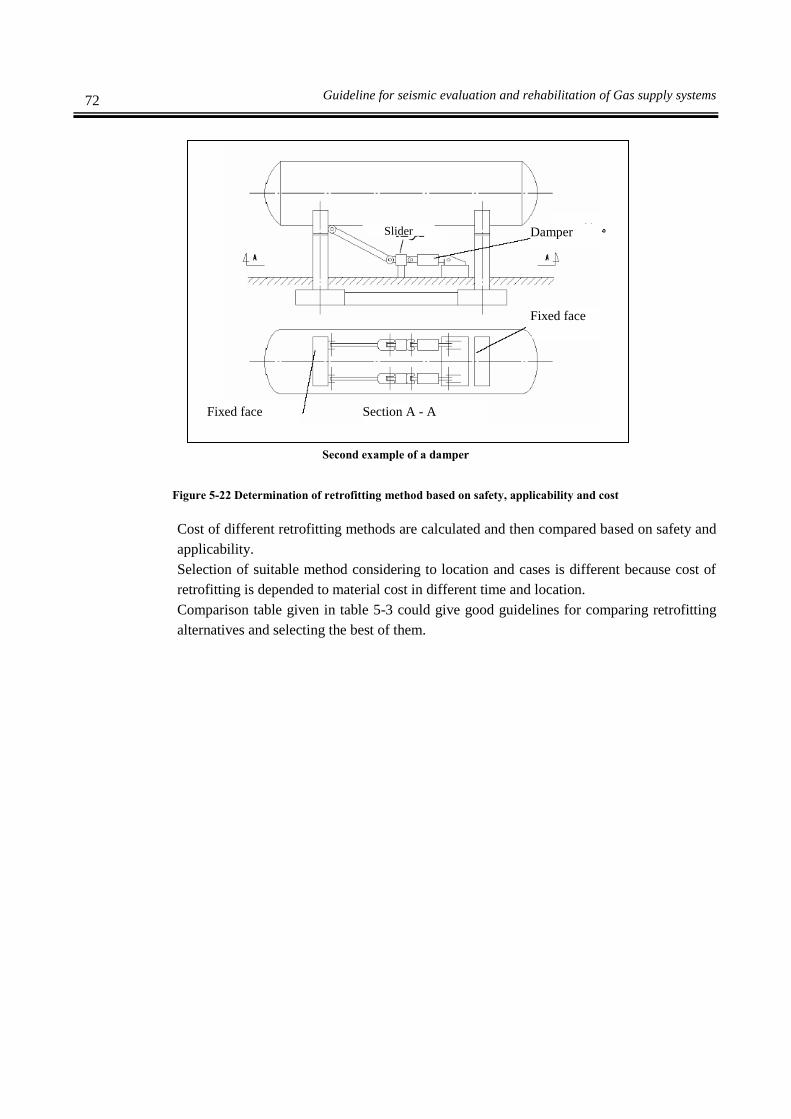
72 Guideline for seismic evaluation and rehabilitation of Gas supply systems
Second example of a damper
Figure 5-22 Determination of retrofitting method based on safety, applicability and cost
Cost of different retrofitting methods are calculated and then compared based on safety and
applicability.
Selection of suitable method considering to location and cases is different because cost of
retrofitting is depended to material cost in different time and location.
Comparison table given in table 5-3 could give good guidelines for comparing retrofitting
alternatives and selecting the best of them.
د
Damper Slider
Fixed face
Fixed face Section A - A

73 Chapter Five- Seismic Retrofitting Methods for Refineries
Table 5-3 Comparison of retrofitting measures
Facilities Method General view
of reinforcement
Retrofitting criteria
Defo
rma
bil
ity
Str
eng
th
Co
st
Ap
pli
cab
ilit
y
Lim
ita
tio
n i
n
pla
n
Vessels
Rei
nfo
rce
anch
ori
ng b
olt
wit
h
add
itio
n o
f d
ivid
ing
pla
tes
○ ● ○ ○ ○
Note When there is improper stress in anchoring bolts
Vessels
Rei
nfo
rcin
g t
he
seat
by
add
ing
bra
ce
○ ● ○ ○ ○
Note When seat strength is not enough
Vessels
Rei
nfo
rcin
g s
eat
by u
se o
f re
info
rcin
g
rin
g
● ● ●
Note In cases where tank stress is more than allowed stress and
Welding is allowed, this method has limitations
● shows the method with best effect, ○ shows the method with good effect and
shows no clear effect (unknown)
5-2-4-other countermeasure
By limiting liquid level inside tank, instead of imposing retrofitting methods, seismic safety could be
increased.
Fillet welding area
Reinforcing ring
Reinforcing ring
Fillet
welding
area

74 Guideline for seismic evaluation and rehabilitation of Gas supply systems
By decrease of liquid level, natural period of structure reduces and seismic force decreases considerably.
In usual performance against earthquake it is assumed that 90% of the tank is filled with liquid. Effective
weight Web is determined according to natural period and modified horizontal seismic force as follows:
5-1 bMHMH W.KF
5-2 LDb WWW
WD: Tank dead weight (kgf)
WL: Stored liquid weight inside tank (upper limit weight after imposing decreasing criteria) (kgf)
: Effective rate of liquid weight obtained from figure 5-23
Figure 5-23 Effective rate of liquid weight
5-3-Tower and vertical tank
5-3-1-Damage modes
Common case of damage is loosening of anchoring bolts and concrete failure.
No damage is exerted on tank due to seismic force.
If wall thickness decrease observed during inspection, safety control of tank is mandatory.
Seismic strength of support section like pier is as important as chambers in towers. Toppling is an
important damage case in a tower.
Tension strength of anchored bolts and buckling stress of pier should be controlled in this type of damage.
a) Damage case in a skirted tower (skirted)
Filling ratio
Eff
ecti
ve
rate
of
liq
uid
wei
gh
t

75 Chapter Five- Seismic Retrofitting Methods for Refineries
i) Shell
1-tension yield
2-compressive buckling
ii) Skirt
1-compressive buckling
iii) Anchoring bolt
1-tension yield
iv) Base plate
1-Bending yield
b) Damage of pier tower
i) Shell
1-tension yield
2-compressive buckling
ii) Pier
1-Yielding
iii) Anchoring bolt
1-tension yield
2-Shear yield
3-Combination of tension and shear yield
iv) Pier connections
c) Damage of handle
i) Shell
1-tension yield
2-compressive buckling
ii) Adjusting bolt
3-tension yield
5-3-2-Seismic assessment
Retrofitting procedure flowchart based on allowable stress method is as follows:

76 Guideline for seismic evaluation and rehabilitation of Gas supply systems
Start
Assessment using detailed inspection
guideline
End
No
YesRepair
Qualitative assessment
Local inspection
No
It needs repair
Yes
Detailed diagnosis
Calculate natural period
Stress calculation of main
body
Stress< Allowed stress
No
End
Dynamic analysisDynamic response
analysis
No
Calculate earthquake intensity
Stress calculation of vessel
Stress calculation of pier
element
Stress< Allowed stress
No
Yes
(1)Skirt type
- skirt -Anchoring bolt
(2)Pier type
- Pier (compression, bending & shear) - Anchoring bolt
(3)Handle type
Seismic capacity of adjusting bolt
retrofittingretrofitting
Yes
Figure 5-24 detailed assessment flowcharts for tower and vessel
77 Chapter Five- Seismic Retrofitting Methods for Refineries
There is another simplified method in order to simplify the analytical model and calculation method from
which is done by extraction method of dominant damage mode and related study to easy evaluation of
existed systems with different installation state.
It is possible to control the stress in support and seismic strength of facilities by extracting dominant
damage mode using allowed stress method.
For facilities with complicated seismic behavior, assessment should be done using detailed assessment
method which included dynamic response analysis and precise modeling.
5-3-3-Tower and vertical vessel retrofitting
Priority for improving tower and vertical vessel is determined by amount of damage to tower and
vertical vessel due to earthquake.
The main factor for prioritizing retrofitting is the importance degree and determined based on site
distance from borders, gas type and pipeline capacity
Major factor is human loss if there is a gas leakage
Other factor is social and economical damage. These factors will affect customers and reconstruction
cost of buildings and etc.
Priority for improving tower and vertical vessel in each damage mode is determined by scale of
affects on tower and vertical vessel in failure.
Affection coefficient is risk degree to human life, reconstruction cost and others.
Simplified detailed evaluation is a method for reducing damage ratio that is created easily.
Necessary factors should be defined for determining of retrofitting priorities.
Basics and method of retrofitting are as follows:
1-Retrofitting based on qualitative assessment
For minor damage, works are limited to a daily inspection and a simple study and quantitative
concept is determined for enhancing seismic strength.
2-Retrofitting based on detailed assessment
a) Points which should be considered in retrofitting plan
Area under pressure should not be operated repeatedly.
Stress concentration and structural discontinuity should be avoided
Balance and harmony between all facilities like workability, dimensions and economic
approach should be provided.
Existing and new structure should act as one unit.
b) Section which should be improved:
In seismic retrofitting, it is necessary to study seismic strength of most of facilities, which have
different specifications and installation requirements.
For this purpose, in this section simplified detailed assessment will be explained based on
damage due to earthquake and a case study.
This method is focused on dominant damage cases and is limited for retrofitting measures related
to damage shape.
Stress in section under study is calculated and seismic strength is determined based on allowed
stress and ultimate strength of element.

78 Guideline for seismic evaluation and rehabilitation of Gas supply systems
In this guideline, retrofitting plan usually is based on simplified detailed assessment with focus
on some damage case. But towers and vertical vessels which are not proper for present conditions
should be studied according to design guideline.
3-Simplified detailed assessment
In simplified detailed assessment it is assumed that there is no considerable damage on tower, skirt,
pier, handle, frame and foundation.
In the first inspection which will be done with high precision, strength reduction due to corrosion
or change and damage due to repair will be studied before detailed assessment.
This is because to consider structure material with specification without corrosion dates.
If structure's specification in construction time has changed due to severe corrosion or repair and
retrofitting, then seismic strength will be controlled with this simple method and plates' effective
thickness will be controlled for corrosion and structure shape will be controlled by drawings for
changes due to repair and retrofitting.
a) Damage mode
In the study of toppling of towers, tension strength of anchoring bolts and buckling strength of
skirt or pier should be considered.
In cone tower (with skirt) compression stress in pier skirt and tension stress in anchoring bolt will
be calculated.
In towers with pier, compression, bending and shear stress will be calculated in base and tension
and shear stress will be calculated in anchoring bolts.
In towers with lug support, tension stress in adjusting bolt should be studied.
Allowed design stress method will be used for new structure.
b) Limit of allowed stress
Limit of allowed stress will be determined by yield strength.
This limit is as follows and is extended to a level to absorb seismic energy with non-elastic
deformation in support structure.
Table 5-4 allowable limitations
Facilities Section Stress type Allowed stress limit
Towers with
skirt supports
Skirt (margin) Buckling
Minimum value of Su
Anchoring bolt Tension Su or 2Sy
Towers with
Pier supports Pier
Buckling
Bending 1.1 Su
Combination 1.1 Su

79 Chapter Five- Seismic Retrofitting Methods for Refineries
Anchoring bolt
Tension Su
Shear uS3
1
Combination
Su
Towers with circular supports (Lug) Adjusting anchor Tension Su
Parameters are as follows:
Su: Tension strength
See: Yield point
E: Longitudinal elasticity module
t: Thickness of skirt plate
Dm: Average diameter of skirt
: Slenderness ratio
: Limit slenderness ratio = F6.0
E2
l: Compression length of pier = 0.7Hl
Hl: Length of pier
i: Minimum gyration radius
I: Minimum moment of inertia of pier
A: Cross sectional area of pier
F: Minimum value of Sy or 0.7Su as standard strength
4-Detailed assessment
The tower and vessel which do not have simplified detailed assessment conditions should be
assessed with design standard.
Retrofitted facilities are controlled and overviewed for overall damage state.
Retrofitting method for enhancing seismic strength is shown in figure 5-25.
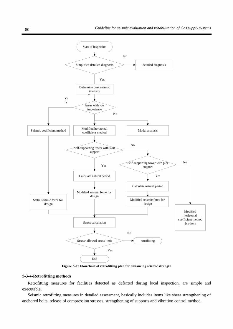
80 Guideline for seismic evaluation and rehabilitation of Gas supply systems
Start of inspection
End
No
Yes
detailed diagnosis
Simplified detailed diagnosis
Areas with low
importance
Modified horizontal
coefficient method
No
Determine base seismic
intensity
Seismic coefficient method Modal analysis
Ye
s
Self-supporting tower with skirt
support
Self-supporting tower with pier
support
No
Calculate natural period
Calculate natural period
Modified seismic force for
designModified seismic force for
designStatic seismic force for
design
Stress calculation
Modified
horizontal
coefficient method
& others
Stress<allowed stress limit retrofitting
No
Yes
No
Yes
Yes
Figure 5-25 Flowchart of retrofitting plan for enhancing seismic strength
5-3-4-Retrofitting methods
Retrofitting measures for facilities detected as defected during local inspection, are simple and
executable.
Seismic retrofitting measures in detailed assessment, basically includes items like shear strengthening of
anchored bolts, release of compression stresses, strengthening of supports and vibration control method.

81 Chapter Five- Seismic Retrofitting Methods for Refineries
1-Concrete crack of foundation
a) When the cracks in concrete are small, resin injection will be used.
b) When there are relatively small cracks in fire-proof coverage, mortar will be used for repair.
2-Bolt corrosion
a) If there is severe corrosion in bolts, first the rusted part should be removed and then painting and
oiling will be done.
b) Bolt and nut which could be separated easily should be replaced.
3-Damage and deformation of support
a) Damaged and deformed part of support should be repaired. In this case, new strength should not
be less than initial strength.
4-Loosening of bolt and nut
a) When the bolt has curve and nut does not fasten completely to base plate, a washer could be used
to fasten the nut to base plate.
5- A connected pipe and others
a) For gas shut off valve and stop valve which are installed beneath the tank and has support from
ground side, a gap between valve and support should be considered to absorb vibration.
b) Nozzle should have sufficient strength against external forces exerted from connected pipes and
pipes' flexibility should be taken into account.
c) During the local inspection, if the flexibility of pipes is judged as insufficient, necessary steps
should be taken according to nozzle strength.
6-Apparatuses and peripheral connected devices
Peripheral devices are fixed with secure connection to tower or vessel.
Related devices are fixed in a platform and this platform is connected rigidly to tower or
vessel.
For peripheral devices which are fixed with an independent frame structure and has short
connecting pipe to tower or vessel, it is recommended to consider the sliding possibility
relative to framed structure of support.
6-1-seismic retrofitting measures based on detailed assessment
Retrofitting measures at least should increase absorbed energy with non-elastic
deformation.
This is based on results of seismic test of a steel tower where by supplying proper non-
elastic deformation for support structure, it could absorb a lot of energy.
The most important measures for seismic retrofitting are as follows.
a) Reduction of seismic force
If seismic force releases, stress on place under consideration will decrease and it
may be possible to reduce stress to below allowed stress limit level.
To reduce seismic response, it is possible to dampen seismic force by use of oil or
viscous-elastic damper.
b) Stress reduction by controlling seismic force of other sections
i) Although seismic force is calculated for skirt, pier and anchoring bolts of tower,
but with distribution and allocating seismic force on different section of tower, it is
possible to reduce induced stress in skirt, pier and anchoring bolt without direct
retrofitting.
ii) Example of these measures are as follows:

82 Guideline for seismic evaluation and rehabilitation of Gas supply systems
Strengthening the support
Strengthening with framed structure
Strengthening with cables
c) Strengthening of area under study
It is possible to reduce stress by increasing cross sectional area to less than
allowed level. If tower's rigidity increases due to strengthening, it is necessary to
recalculate response analysis.
6-2- seismic retrofitting measures for tower
Figure 5-26 Seismic retrofitting of tower
) ه
ا (
ا
ا ه
ا
2 ه
Strengthening
Strengt
hening
Strengthening
Strengthening with
scaffold
Strengthening
inside & outside
of skirt of vessel
Strengthening with
supporting structure
Strengthening with
damper
Seismic strengthening
of two tanks with
viscous damper
Tower strengthening
with cable

83 Chapter Five- Seismic Retrofitting Methods for Refineries
5-3-5-Determine retrofitting method from safety and cost stand point of view
According to seismic retrofitting measures which are obtained by detailed assessment, necessary shapes
and sizes will be determined based on simple design method or precise method together with details.
Then costs will be calculated and workability related to that location will be studied and execution
procedure will start.
As retrofitting cost depends on cost of material, time and location, the selection of proper method usually
depends on the case and location.
As a reference for list of real methods, for retrofitting plan and cost calculation, comparative charts for
one of given methods is shown as follow.
Table 5-5 Comparison of retrofitting criteria
Facilities Method General view of strengthening
Retrofitting criteria
defo
rma
bil
ity
Str
eng
th
cost
exec
uta
ble
Lim
ita
tio
n i
n
pla
n
towers Strengthening skirts by adding plate
Note In cases where skirt strength is low
shows the best effect, good effect and no clear effect
Another method to decrease seismic force is to reduce liquid level in the tank.
5-4-Spherical tank
5-4-1-Damage modes
Damage modes and control criteria for spherical tanks are as follows:
a) Damage to rod of bracing
tension yielding
b) Damage to upper column
Compression buckling, yield or yield due to bending
Shear yield
Weld strip

84 Guideline for seismic evaluation and rehabilitation of Gas supply systems
Combination of compression yield, bending and shear
c) Damage to lower column
Combinational buckling, yield or buckling yield
d) Damage to anchoring rod
Tension yield
Shear yield
Combination of tension yield and shear
e) Damage of shear plate
Buckling yield
Shear yield
Combination of bending yield and shear
f) Damage to base plate
Bending yield due to pressure from foundation concrete
Bending yield due to tension force from bracing rod
Schematic view of these damages is shown in figure 5-27.
Figure 5-27 Damages to spherical tanks

85 Chapter Five- Seismic Retrofitting Methods for Refineries
5-4-2-seismic assessment procedure
Detailed assessment is done for each damage mode according to latest design standard. Retrofitting
procedure based on allowed stress method according to new standard is shown in figure 5-28.

86 Guideline for seismic evaluation and rehabilitation of Gas supply systems
Start
Assessment using detailed inspection
guideline
End
No
YesRepair
Qualitative assessment
Local inspection
No
It needs repair
Yes
Detailed diagnosis
Calculate natural period
Stress calculation of main
body
Stress< Allowed stress
No
End
Dynamic analysisDynamic response
analysis
No
Calculate earthquake intensity
Stress calculation of vessel
Stress calculation of pier
element
Stress< Allowed stress
No
Yes
(1) Bracing
(2) Column
(3) anchor
(4) shear plate
retrofittingretrofitting
Yes
Figure 5-28 Assessment procedure for spherical tanks
Another simple method for simplification of model analysis and calculation is presented.

87 Chapter Five- Seismic Retrofitting Methods for Refineries
In this method, dominant damage and related items for easy assessment of facilities with different
installation conditions is presented.
This method is used for stress calculation of materials in support structure and judging the facilities
strength against earthquake and is based on allowed stress method.
If qualitative assessment method is used, its consistency with prerequisite of local inspection should be
controlled with precise consideration of damage mode and allowed stress limit.
For those facilities which are not consistent with analysis prerequisites, detailed assessment including
dynamic response analysis and precise modeling should be sued for assessment.
5-4-3-Retrofitting measures for spherical tanks
Priority for retrofitting measures of spherical tank is based on amount of damage to it during earthquake.
Usually retrofitting priority factor is based on degree of importance and is determined by site distance
from borders, gas type and pipeline capacity.
Here pipeline capacity means volume of liquid which could hurt human if it is leaked.
Among other factors are economical and social factors. These factors could affect customers and
reconstruction cost of buildings and etc.
Retrofitting priority for spherical tanks in each damage mode will be determined by the scale of its
effects.
Simplified detailed evaluation is a method for reducing amplitude that is created easily.
Related factors should be determined for assigning retrofitting priorities.
Basics and method of retrofitting are as follows:
1-Retrofitting based on detailed assessment
For minor damage, works are limited to a daily inspection and a simple study and quantitative
concept is determined for enhancing seismic strength.
For major damage, this study will be done by detailed assessment.
2- Points which should be considered in retrofitting plan.
2-1-
Area under pressure should not be operated repeatedly like as before.
Structural discontinuity and stress concentration should be avoided.
Balance and harmony between all facilities like workability, dimensions and economic
approach should be provided.
Present and newly constructed structure should act as one unit.
2-2- The section which should be improved:
In this guideline, retrofitting measures to limit sections that are vulnerable to damage mode
concentration in spherical tanks and easy seismic strength control of facilities and their
installations are explained.
3- Simplified detailed assessment
3-1- Conditions to use simplified detailed assessment
Following conditions should be met in order to be able to use simplified detailed assessment.
All drawings, specifications, and conditions of spherical tanks should be studied thoroughly
to be sure that the requested conditions are met.
There should be no severe corrosion in tank, protecting structure and elements of foundation.
Weight, shape and calculated sizes should be consistent with major structure.

88 Guideline for seismic evaluation and rehabilitation of Gas supply systems
Piping and its piers should not have great effect on seismic behavior of main structure.
Tank should be considered as one solid body.
Spherical tank should not have torsion vibration.
Foundation sits directly on the ground.
Braces between column connections should be arranged as pairs.
Column to foundation connection should be considered as hinge.
3-2-Damage modes and categorization of studies
Considering the damage mode of spherical tank body (toppling), tension strength and failure of
support structures should be studied:
Bracing
Column
Anchoring bolt
Shear plate
3-3-Limit of allowed stress
Allowed limit for tension stress for bracing is 3Sy for ordinary steel and high strength steel is
(cable) 2Sy. (Sy is yield stress)
Allowed limit for tension stress for anchoring bolt is uS)/( 31 . Su is ultimate strength.
Simplified retrofitting plan for enhancing seismic strength is shown in figure 5-29.
4-Detailed assessment
Seismic performance of spherical tank, which does not have simplified detailed assessment
conditions, should be studied and assessed by use of design standard including measured data and
qualified assessment method.
Stress condition in improved facilities should be revised and controlled for total damage.

89 Chapter Five- Seismic Retrofitting Methods for Refineries
Start
Acceptable
No
YesDecrease in liquid level
Necessary tools for study
No
Accepting decrease in liquid level
Vibration control or system
isolation
Bracing strength Strengthening of
diagonal element
Vibration control &
seismic isolation
Column strength Column strengthening
Yes
Response analysis
Calculate stress in main
element
Stress assessment
Acceptable
Strengthening shear
plate
Shear plate strength
Strengthening anchoring
bolt
Anchor bolt strength
Yes
No
Yes
No
yes
No
Yes
No Yes
No
Figure 5-29 Simplified detailed assessment flowchart for retrofitting measures of spherical tank
90 Guideline for seismic evaluation and rehabilitation of Gas supply systems
5-4-4-List of retrofitting methods
Retrofitting measures for facilities, which are diagnosed as defected in local inspection (walking
along the project line and assessing) are simple practical works.
Seismic retrofitting measures based on detailed detection method usually consists of shear
strengthening of anchoring bolts, stress decrease in supports, strengthening of support structure and
vibration control method.
1-Retrofitting measures based on results of field studies
Retrofitting measures for facilities, which are recognized defected during study, are as follows:
These works usually are simply doable.
Study of structure safety during construction and retrofitting effects should be done in advance.
1-1- Crack in foundation
If there is crack in foundation, resin will be injected, but crack sizes should be small relatively.
1-2-Corrosion
If there is serious threat to bolts, first the rust should be removed and then painting and oiling
should be done.
1-3-Aging of bolts and nuts
Bolts will be threaded again and nuts will be replaced with new ones.
1-4-Loosening
a) If bolt is bent and nut is not placed properly in its place and does not sit completely on the
base plate, it should be fixed by inserting washer between base plate and bolt.
b) Bolts are fastened steadily using special wrenches.
1-5-Adding pipe
a) It is recommended that adding place of pipe be anchored directly from tank side.
b) Stairs, corridors and … should be located beside main structure on the ground or inside the
main structure.
c) Supporting pipes for measuring devices and valves should be short.
d) Valves and pipes should be connected to tank even if they are anchored with short pipes so
they behave like a solid structure and have the same seismic characteristics.
e) It is recommended to consider a void space between valve and supports in exit valve and stop
valve, which is connected beneath the tank and is protected by ground.
f) Pipe outlet has sufficient strength against exterior pressure and pipe flexibility also should be
considered.
g) It is recommended that pipes connecting adjacent tanks have U-shaped and knee bend.
h) Pipes entering supporting walls of liquid tanks should have curves and direct pipe should be
avoided.
i) It is recommended pipes which enter ground have bends in the beginning.
2-Seismic retrofitting measures based on detailed assessment
2-1-Strengthening of braces
When bracing strength is not sufficient, following retrofitting measures will be done.
If the brace is already strengthened, seismic performance considering total stiffness of retrofitting
tank should be checked again.
a) Additional brace
In retrofitting measures, lateral plate should be connected with pinned connection.
As it is seen from following figure items (b) and (c), similar considerations is necessary.

91 Chapter Five- Seismic Retrofitting Methods for Refineries
Figure 5-30 Strengthening by adding anchored bracing
b) Moving of anchoring rod
Instead of anchoring rods with small diameter, strong, stiff and big diameter rods should be
used.
c) Increase steel bracing cross sectional area with circular cross section.
Cross section of circular brace will increase by welding of new angles.
2-2-Strengthening of column
Total stiffness of tank will be assessed considering strengthened column and bracing.
Figure 5-31 shows the strengthening by welding of angle to column.
When upper columns need retrofitting, lower columns also should be strengthened in similar way.
Column reinforcement
Column
Reinforcemen
t
A-A cross section
Middle of
tank

92 Guideline for seismic evaluation and rehabilitation of Gas supply systems
2-3-Reinforcing anchor
a) Reinforcing tension anchor
Additional anchoring bolt (1)
Figure 5-31 adding anchoring bolt (1)
Additional anchoring bolt (2)
Figure 5-32 adding anchoring bolt (2)
b) Shear reinforcement of anchoring bolt
Adding anchoring bolt
It is similar to above article
Additional anchoring bolt (2)
It is similar to above article
Reinforcement with shaped steel
Existing anchoring bolt
Shearing plate
Additional anchoring bolt
Wing plate for diagonal
member

93 Chapter Five- Seismic Retrofitting Methods for Refineries
Figure 5-33 Reinforcement with shaped steel
2-4-Vibration control method and seismic separation
Vibration control is a method to increase damping in structure and decrease vibration reaction.
Seismic separation is a method to decrease seismic reaction by modifying vibration mode and
structure's period.
a) Vibration control using damper (figure 5-34 and 5-35)
Figure 5-34 Vibration control with damper (standard type)
Side anchoring clips
Foundation
Anchoring
bolt and
frame
Oil damper
Section A
Anchoring
clamp on
side of
foundation
Centerline
Details A
Spherical tank
Existing anchoring bolt
Wing plate
Reinforcing
Column
Anchoring bolt
Reinforcing
Reinforcing welding
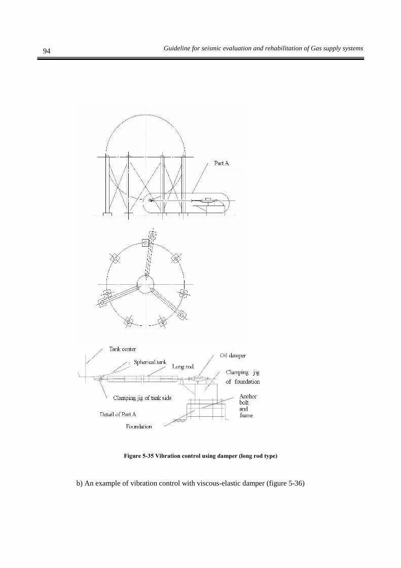
94 Guideline for seismic evaluation and rehabilitation of Gas supply systems
Figure 5-35 Vibration control using damper (long rod type)
b) An example of vibration control with viscous-elastic damper (figure 5-36)

95 Chapter Five- Seismic Retrofitting Methods for Refineries
Figure 5-36 Vibration control using viscous-elastic damper
c) Example of seismic separation using inertia dampers including pendulum and rod (figure 5-
37)
Figure 5-37 Example of seismic separator using inertia damper including pendulum and rod
5-4-5-determining retrofitting method from safety, workability and cost point of view
According to different seismic retrofitting measures, shapes and sizes of initial plan will be prepared.
Damper
Damper
) (
ه
دا ه ا
د
) (
Hinged connection
Connecting rod
Support weight
Pendulum
Pendulum
seismic
separator

96 Guideline for seismic evaluation and rehabilitation of Gas supply systems
After that, cost and workability at site will be compared and then construction of final retrofitting plan
will start.
As the material cost will change by time, retrofitting type will be determined based on time and location.
For each retrofitting method, a comparison table should be prepared including structure strength, cost, and
workability and plan limitations.
Limiting liquid level in tank to reach safe conditions against earthquake, could cancel out the need for
retrofitting.
1- Decreasing seismic input force by decreasing liquid level
Usually the behavior of tank against earthquake is determined when the liquid level in tank is 90%.
Effect weight (Wb) will be determined according to natural period and modified horizontal
earthquake force as follows:
bMHMHWKF .
5-3
LDbWWW 5-4
Where
Wd: Tank dead weight (kgf)
WL: Weight of liquid inside tank (upper limit weight after considering decreasing works) (kgf)
: Effective rate for liquid weight
Liquid level will decrease earthquake force considerably.
Figure 5-38 Effective rate for liquid weight
Eff
ecti
ve
rate
of
liq
uid
wei
gh
t
Filling ratio

97 Chapter Five- Seismic Retrofitting Methods for Refineries
5-5-Foundation
5-5-1-damage modes
Necessary places for seismic studies are as follows:
Anchoring bolts and anchoring plates
Pedestal
Footing
Pile
Part of damaged foundation is shown in following figure (figure 5-39)
Figure 5-39 Damage modes in foundation
Lateral movement damages due to liquefaction are as follows:
Failure of piles (underground)
Failure of pile cap due to earthquake movement
Failure of pile cap due to reduction of lateral strength in liquefaction
Failure of pile cap due to inertia force
Deviation due to reduction of bearing capacity of ground in spread foundations.
5-5-2-assessment procedure
Assessment procedure for foundation of spherical tank is shown in figure 5-40.
Contacting pressure
Horizontal force
Pedestal
Ordinary foundation
Compression force
Pile Uplifting force
Contacting pressure with
ground
Compression capacity
Anchoring bolt
Pile foundation

98 Guideline for seismic evaluation and rehabilitation of Gas supply systems
Start
Acceptable
Yes
No
Does it need repair?
Qualitative assessment- local
inspection
Necessary seismic
workability
Repair
Detailed diagnosis
Dynamic response analysis
End
No
Yes
Dynamic analysis
Assessment with code
Earthquake intensity 0.3<
Alternative methods
Data related to loading of
facilities and pipe support
structure
Liquefaction assessment
Acceptable stress Ductile design
LiquefactionPile
foundation
Mat
foundation
Stability of
under ground
level soil
Pile strength Ground
stability
Foundation
strength
Stress< acceptable stress
Updating
Deformation ratio< acceptable elastic
deformation ratio stress
Movement and
settlement due to
liquefaction
Seismic inertia force
analysis
Reduction of soil
parameter Seismic inertia
force analysis
No
Yes Yes
No
YesNo
Yes
No
Yes
Yes
No
Figure 5-40 Foundation assessment flowcharts

99 Chapter Five- Seismic Retrofitting Methods for Refineries
5-5-3- Foundation retrofitting
Retrofitting priority will be determined based on damage intensity to damaged facilities due to
earthquake.
Main factor to prioritize retrofitting measures and change of parts is their importance and it is calculated
based on their distance from the site.
Also gas type and pipe capacity which is relate to human lives in case they leak. Another factor is the
social and economic scale.
Of course, other factors like limitation on customer, reconstruction cost and etc are effective as well.
Damage points usually are concentrated in pier, foundation and piles and retrofitting measures are
different depending on the location.
Retrofitting priority is considered with pressure intensity of facilities on foundation. In cases where the
foundation is damaged those facilities which are closer to foundation have higher priority.
In the following cases, foundation should be retrofitting:
a) Strength and deformation capability of old foundations is low or for seismic reinforcement of
facilities over foundation, yield strength of foundation is improper.
b) A foundation with low strength against liquefaction
c) Lateral spread due to liquefaction
In qualitative assessment, necessary data together with local inspection data should be collected.
In seismic retrofitting of old foundations, initial data like foundation type, shape, dimension and etc
are unclear in most of the time.
Retrofitting design will be done by determining initial data like rebar's arrangement and etc.
Local excavation for investigation, uncovering part of cover concrete, non-destructive test or
reverse analysis according to design standard during foundation construction, will be used for
estimation of main or initial data.
Foundation detailed assessment should be based on detailed assessment of facilities located over
the foundation.
Seismic retrofitting procedure of foundation is shown in figure 5-41 together with above-mentioned
items.

100 Guideline for seismic evaluation and rehabilitation of Gas supply systems
Start
End
NoCan it withstand existent load?
Initial diagnosis (local
inspection)
Seismic target performance
Foundation
retrofitting
Is seismic performance acceptable?
No
Yes
Seismic performance assessment of foundation
based on detailed diagnosis results of facilities
Foundation damage amount (ground loading capacity is insufficient
or lack of load bearing capacity of pile )
Yes
Adjusting conditions for seismic retrofitting
Strengthening target
Type of substructure and super structure
Damage type (insufficiency of ground loading capacity or
element's yield strength )
Structure condition
Possibility of retrofitting Review for reconstruction
Selection of seismic retrofitting measures
(i) Retrofitting measures for insufficiency of
ground bearing capacity
(ii) Retrofitting measures for insufficiency of
element yield strength capacity
Planning retrofitting measures
Is seismic performance acceptable?
No
Yes
No
Yes
Figure 5-41 Foundation retrofitting plan flowcharts
5-5-4-List of retrofitting methods
Retrofitting measures for facilities, which are detected as defected during local inspection, are simple
practical works. Seismic retrofitting measures based on detailed assessment usually include pier
reinforcement and adding piles.
1-Retrofitting measures based on local inspection results

101 Chapter Five- Seismic Retrofitting Methods for Refineries
Relatively small cracks in pier and foundation will be filled with resin injection.
2-Retrofitting measures in detailed assessment
2-1-Pier reinforcement
This item will be done when shear and compression strength of pier is improper.
Reinforced concrete will be reinforced when its flexural capacity is improper.
Foundation weight will be increased when the foundation tension is improper. They are shown in
table 5-6.
2-2-Different type of seismic reinforcement for foundation and ground
There is no precise definition for seismic retrofitting solely for foundation.
Retrofitting or seismic reinforcement is divided into two categories namely; seismic
reinforcement due to lack of ground bearing capacity and second is to overcome the lack of
material strength.
Summary for each case of seismic retrofitting is given in table 5-6.
Table 5-6 Different type of seismic reinforcement for foundation
Seismic reinforcement when
strength of foundation material
decreases
Seismic retrofitting for
enhancing foundation stability Seismic reinforcement
type
Foundation type
Ad
dit
ion
al p
ile
Po
st t
ensi
on
ing
Lo
ad r
edu
ctio
n
Incr
ease
dim
ensi
ons
of
foun
dat
ion
(fi
llin
g)
Co
mm
on
load
wit
h o
ther
typ
e o
f fo
und
atio
n
Ad
din
g c
on
cret
e o
r st
eel
pla
te c
ov
erag
e
Lo
ad r
edu
ctio
n
So
il s
tabil
izat
ion
Ad
dit
ion
al p
ile
Incr
ease
dim
ensi
ons
of
foun
dat
ion
Co
mm
on
load
wit
h o
ther
typ
e o
f fo
und
atio
n
Fo
und
atio
n c
on
stru
ctio
n
wit
h e
xca
vat
ion
fro
m
bott
om
- Ordinary foundation
Foundation on the pile
- - - - - - - - Large scale foundation (steel
pipe, diaphragm wall)
- - - - Relative to ground motion
- - Relative to inertia force
Is a method, which is effective, is a method, which is not very effective and – is not used at all.
2-3-Examples of adding piles
This method is used when load-bearing capacity of structure is improper.
Load bearing capacity will be strengthened by adding sections to existent structure.
Between added sections, adding pile is the most common method.
Another method is cast-in-place of diaphragm wall.
Adding piles with small sized diameters, which is called micro pile has developed recently.
Another method is connecting old and new foundation, which is done by increasing dimensions
of existent foundation by adding pile to perimeter of foundation. It is shown in figure 5-42.
Load distribution among old and new piles depend on dimensions, structure type and
construction conditions.
Vertical load except for seismic load of existent foundation will be beard by previous piles and
horizontal load will be beard by both types of piles (old and new).

102 Guideline for seismic evaluation and rehabilitation of Gas supply systems
Special note should be given to integrity of news and old foundation.
Figure 5-42 Examples for added piles
5-5-5-Determining retrofitting type based on safety, practicality and its cost
For execution of seismic retrofitting of foundation, after determining its degree in different damage
modes, retrofitting measures, construction type and total degree of retrofitting should be specified
considering foundation damage degree from its workability and assessment results.
Study of following items after determining retrofitting criteria is necessary:
1-Construction volume
2-Foundation type
3-Foundation damage type
4-Construction and ground conditions
In design of seismic retrofitting of foundation facilities, shape and dimension will be determined by
design standard.
When the foundation strength is improper, foundation retrofitting and its type will be determined.
Estimated cost and comparative studies also will be done. As the material cost varies by time, retrofitting
type will be determined by time and location.
For the ease of engineers who study executable methods, above-mentioned items are compared in tables
5-7 in retrofitting planning based on cost, design type and its elements.
Existing piles
Added piles

103 Chapter Five- Seismic Retrofitting Methods for Refineries
Table 5-7 comparison of retrofitting measures
Sec
tio
ns
Met
ho
d
General view of
Reinforcement
Retrofitting measures type
Def
orm
abil
ity
Str
eng
th
Co
st
Wo
rkab
ilit
y
Lim
itat
ion i
n p
lan
Ped
esta
l
Rei
nfo
rced
con
cret
e
Note Flexural reinforcement
Sec
tio
ns
Met
ho
d
General view of
Reinforcement
Retrofitting measures type
Def
orm
abil
ity
Str
eng
th
Co
st
Wo
rkab
ilit
y
Lim
itat
ion
in
pla
n
Ped
esta
l
Rei
nfo
rced
con
cret
e
Note Shear reinforcement

104 Guideline for seismic evaluation and rehabilitation of Gas supply systems
S
ecti
on
s
Met
ho
d
General view of
Reinforcement
Retrofitting measures type
Def
orm
abil
ity
Str
eng
th
Co
st
Wo
rkab
ilit
y
Lim
itat
ion
in
pla
n
Fo
un
dat
ion
Fo
un
dat
ion
rei
nfo
rced
by
add
ing
pil
e an
d
bro
aden
ing
of
cro
ss s
ecti
on
of
fou
nd
atio
n
Note For cases where yield strength of existent piles and pullout strength of present piles is
insufficient
Sec
tio
ns
Met
ho
d
General view of
Reinforcement
Retrofitting measures type
Def
orm
abil
ity
Str
eng
th
Co
st
Wo
rkab
ilit
y
Lim
itat
ion
in
pla
n
Fo
un
dat
ion
Co
ncr
ete
tie
bea
m r
einfo
rced
by
bro
aden
ing
of
cro
ss s
ecti
on
Note For cases where yield strength of ground beams (connecting tie beams) is
insufficient
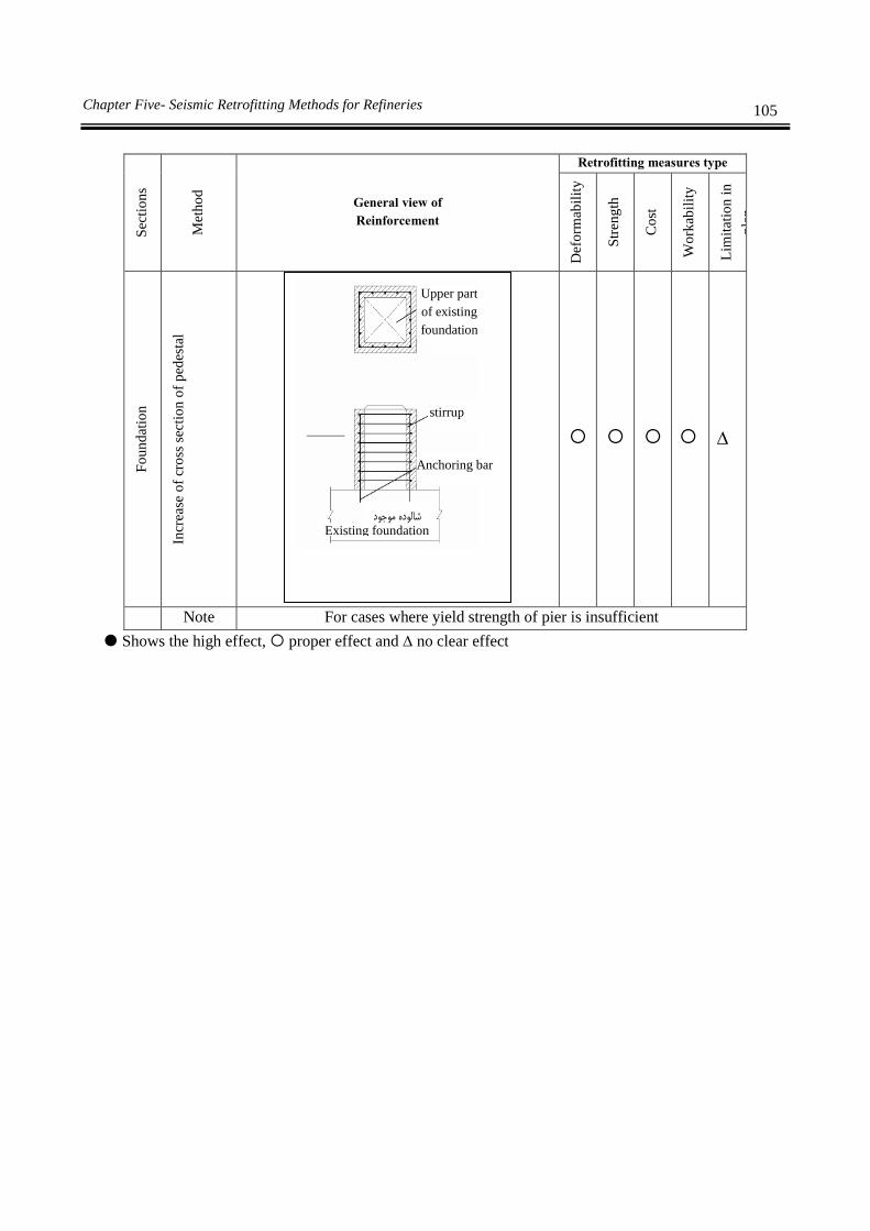
105 Chapter Five- Seismic Retrofitting Methods for Refineries
S
ecti
on
s
Met
ho
d
General view of
Reinforcement
Retrofitting measures type
Def
orm
abil
ity
Str
eng
th
Co
st
Wo
rkab
ilit
y
Lim
itat
ion
in
pla
n
Fo
un
dat
ion
Incr
ease
of
cro
ss s
ecti
on
of
ped
esta
l
Note For cases where yield strength of pier is insufficient
Shows the high effect, proper effect and no clear effect
Upper part
of existing
foundation
stirrup
Anchoring bar
Existing foundation
Chapter 6
Tanks retrofitting methods


109 Chapter Six- Tanks retrofitting methods
6-1-Types of tank
Tanks with cylindrical shell and spherical or conical roofs are used for pressures less than 35 kPa.
Floor of these tanks could be flat or like their roof and usually they need supporting structure of the shell.
For pressures more than 35 kPa usually semi spherical, spherical and network spherical tanks will be
used. These types of tanks have valves for preventing pressure increase more than designed values. Tanks
with simple spherical roof and network spherical roof are shown in figures 6-1 and 6-2. Figure 6-3 shows
the cross section and figure 6-4 shows spherical floor with curved lump or soft change in shape in the
common border of shell and upper part.
In semi spherical tanks elements with different radiuses are used which a flat shape is obtained.
Networked semi spherical tanks are used for larger volumes and internal stirrups and supports will help
for shell stress distribution.
Figure 6-1 simple half spherical tank
Figure 6-2 networked semi spherical tank

110 Guideline for seismic evaluation and rehabilitation of Gas supply systems
Figure 6-3 drawing of a semi sphere tank
Figure 6-4 simple semi spherical tank with lumped curve
6-2-Retrofitting
Quantitative assessment and analysis of tanks could be done with numerical methods using three
dimensional modeling. Loading and analysis method is similar to analysis and design of new tanks.
Prioritization of tanks and components retrofitting should be done according to following parameters.
a) Age: Prioritization of tanks for seismic vulnerability will start from the simplest group.
Those tanks which are constructed without seismic design consideration in high and very
hazardous areas will be the first group to be assessed for seismic vulnerability. Second priority
is those tanks constructed in medium and low hazardous areas.
b) Height to width ratio: Tall and slender tanks are more vulnerable compared to short and wide
ones. Shells compression stresses increases, elephant foot buckling occurs and this increases
possibility of total toppling. In addition, tall tanks displaced more than short ones.
c) Construction detail: Riveted tanks are more vulnerable comparing to welded ones.
Section
Maximum liquid level
Front view

111 Chapter Six- Tanks retrofitting methods
It is possible in very old tanks that butt or lap weld with partial penetration was used. Damage to
these connections in a severe earthquake is much more than structures which their connections
have complete penetrated welds.
In old tanks sensitivity of steel to environment temperature is high which means rapid
deformation due to seismic forces could lead to brittle fracture.
d) Attachment details: Most of the damage in seismic disasters is caused by break in piping, ladder,
stage or other fixed facilities due to displacement in tank wall.
e) Anchored tanks: In anchored tanks compression tension of shell is considerably lower
comparing to unanchored tanks. Also displacement due to uplift forces in anchors and fixed
displacement of components and piping connected to tank will decrease.
f) Unanchored tanks: Major difference between seismic responses of anchored and unanchored
tanks, is displacement due to uplift forces. This displacement is usually visible in the edges of
unanchored tanks. This uplifting force will produce huge tension, compression and moment in
the walls of tank and base plates and their intersections. Changes in execution details of tanks
might amplify the effects of uplifting force in tanks. In many cases it is necessary to do
retrofitting measures for these seismic vulnerable elements.
Damage priority in tanks is as follows:
Complete toppling of tank
Slide of whole tank
Total buckling of tank shell due to pressure stresses or sloshing effects
Uneven settlement and unstable supporting
Uneven settlement and unstable soil beneath the foundation (landslide or liquefaction)
Instability of floating roofs
Damage to fixed or floating roofs
Damage to connection and welds
Stretch out of anchor bolts
Overflow of liquid
Other damages
6-3-1-Omission or replacement of shell plates
6-3-1-1-Minimum thickness for replacing plate of shell
1-Minimum thickness of replacing plate of shell should be determined by design standard. This
thickness should not be more than the nominal thickness of the surrounding plates unless the
surrounding plates are thickened.
2-Any change in major design conditions like specific weight, design pressure, liquid level and
shell height should be considered.
3- Plates with same thickness should be used if only few plates are replaced.
4- If all shell plates are replaced, new plates could be thicker.
6-3-1-2-Minimum dimension of replaced shell plates
1- Minimum dimension of replaced shell plates is 300 mm or 12 times of replaced plate thickness
which ever is greater. Replaced plate could be circular, rectangle, square with chamfered
112 Guideline for seismic evaluation and rehabilitation of Gas supply systems
corners or rectangle with rounded corners unless when all shell plates are replaced. For
acceptable details of replaced shell plates refer to figure 6-5.
2-When one or all shell plates or segments with same heights as shell plates are omitted or
replaced, minimum space requirement for vertical welding should be obeyed. In omission or
replacement, all shell plates or segments with same heights should be improved upon cutting
and second welding along the horizontal welding connections. Before welding new vertical
connections, existing horizontal welds should be cut so that at least 300 mm space up to new
vertical connections remains. Vertical connections should be welded before horizontal
connections.
3-When one or all shell plates or segments with same height as shell plates are omitted or replaced,
minimum space requirements and welding length in last pitch should be obeyed.
6-3-1-3-Welding connection design
1- Residual strains due to welding of replaced plates could be much bigger comparing to newly
built tanks and it is necessary that design should be done in a way to decrease these strains.
2- Shell replaced plates should be welded by butt method with complete penetration and melt
unless covered connection should be allowed for shell repair.
3- Weld connection design for replaced shell plates should be done according to API STD 650.
3.1.5.11 to 3.1.5.3. Connections in shell tanks with lapped welds could be repaired with
construction standard. Welding details should be according to API Std 650, 5.2
4- For existing shell plates with thickness more than 0.5 inch outer edge of butt weld connected to
replaced shell plate should be at least 8 times weld thickness or 10 inch from outer edge of
existing shell connection with lap weld, whichever is bigger. For existing shell plates with
thickness 0.5 inch or less, distance could be decreased up to 6 inch from outer edge of vertical
connection or 3 inch from outer edge of horizontal connection.
For existing shell plates with thickness greater than 0.5 inch, outer edge of butt weld connected
to replaced shell plates should be at least 8 times weld or 10 inch from edge of strip weld
connecting floor shell to floor, except when replaced shell plate is extended and plate
connection to floor is almost 90 degree.

113 Chapter Six- Tanks retrofitting methods
1-
All weld junctions should be vertical or in other words 90 degree.
2-Before new vertical welding, existing horizontal welds should be removed for at least 12 inch from edge of vertical
weld. Horizontal welding should be done at last.
3-Before new vertical welding, plate weld to existing floor should be removed for at least 12 inch from edge of vertical
weld. Weld removal should continue at least for 3 inch or 5t from cut of floor plate weld. Plate welding to the floor
should be done at last.
4-Minimum distance from edge of welds to determine replacing plate's thickness, t
Dimension ≥0.5t inch <0.5 t inch
R 6 inch bigger than 6 inch or 6t
B 6 inch bigger than 10 inch or 8t
H 3 inch bigger than 10 inch or 8t
V 6 inch bigger than 10 inch or 8t
A 12 inch bigger than 12 inch or 12t
C bigger than 3 inch or 5t
(A) Replacing of only one shell plate
Existing welds
Existing welds
Spot welding
(Floor or annular plate)
Refer to annotation No 2
Refer to annotation No 3
Floor plate
Greater than
R or H

114 Guideline for seismic evaluation and rehabilitation of Gas supply systems
(B) Replacing of several shell plates
(C) Replacing of shell plate at floor
(D) Replacing of middle shell plate
Figure 6-5 Details of plate replacement in steel tanks
t: shell plate thickness : welding in last step
Figure 6-6 Requirements for minimum distance and welding length in last step for replacing shell plates
For existing shell plates with thickness 0.5 inch or less, distance could be decreased to 6 inch for
shell plates with unknown hardness where they have not satisfied criteria of figure 6-6. Edge of
each vertical weld connection of a replacing plate should be 3 inch or 5 times thickness away
from weld connection edge in floor annular ring or weld connection in floor plates beneath
tanks shell. Minimum dimensions are given in figure 6-5.
5- In order to decrease distortion potential due to welding, heat, input flux and welding steps should be considered.
6-3-1-4-Reinforcing shell plates
1-Repairing of shells with covering connections is an acceptable repair method for riveted, lap and
butt weld tanks. The aim of these repairs is permanent repairs related to inspection and
continuous maintenance plans. These requirements are for assessment of shell repair with
covering connection although it is not necessary to impose plate thickness limitations.
Floor or annular plate
Horizontal line

115 Chapter Six- Tanks retrofitting methods
2-All repair materials should be provided according to this guideline requirements and API Std
653.
3-Above repairing method should not be used for shells (main construction) with thickness more
than 0.5 inch or for replaced cap or shell plates.
4-Repair plate material should be 0.5 inch or the thickness of adjacent shell plate whichever is
smaller and should not be less than 3.16 inch in any case.
5-Repair plate shape could be circle, four cornered, square or rectangle. All corners should be
rounded with minimum 2 inch radius except for shell to floor connection. The shape of
reinforcing plate of nozzle according to API STD 650 is also acceptable.
6-It is possible that repair plate passes through vertical or horizontal shell strips with butt weld in
the same line as ground line but there should be at least 6 inch overlap between shell strips.
Weld spacing requirements shown in figure 6-5 should be used as a base for locating repair
plate's position in butt weld, fillet weld method and rivet strips and other repair plates.
7-If vertical faces have 90 degree angle with tank floor and the welding of floor to shell is not
according to figure 6-5, it is possible that repair plates have extended to outer connection of
plate to the floor. Repair plates inside shell should be located in a way that open gap of weld be
at least 6 inch toe to toe up to floor to shell welding.
8-Maximum dimension of repair plate is 48 inch in vertical and 72 inch in horizontal. Minimum
dimension for repair plate is 4 inch.
9-Openings in shell and their reinforcements should not be located in covering connections.
10-Before using covering connection on repair shell, those places which will be welded, should be
inspected for defects and remaining thickness by ultrasonic methods.
11-Repair plates should not have over laps with welded shell strips, riveted places, other repair
plates, places with distortion or cracks and unrepaired defected places.
12-Covered connection repair plates will be used for capping opening holes or places with high
corrosion.
13-Welding should be continued to outside of repair plate region and inside perimeter of hole.
Minimum diameter of hole is 2 inch and minimum corner radius for shell openings is also 2
inch.
14-Nozzle opening and reinforcing plates should be separated completely before connecting repair
plate.
15-Welds of repair plate should be complete fillet type. Minimum shell plate dimension is 4 inch
with minimum 1 inch over lap and maximum 8 times shell thickness over lap.
16-Repair plate thickness should not exceed adjacent plate nominal thickness.
17-Repair plates with covering connections could be used for reinforcing of those areas of shell
plate which have damaged severely and doesn't have enough strength to bear service loads.
These plates also could be used for shell plates which their thickness is insufficient and they
have to comply with following additional requirements.
18-Thickness of repair plates will be selected based on approved design using API STD 653 and
as-built standards and connection efficiency not more than 35%. Peripheral welding should be
complete fillet type.
19-Repair plate thickness should not exceed 4/3 of shell plate thickness which is located on the
perimeter of repair area, and it should not be more than 1/8 inch. Repair plate thickness should
not exceed 1/2 inch.
116 Guideline for seismic evaluation and rehabilitation of Gas supply systems
20-Residual strength of the area which is damaged should not be considered for hydrostatic and
service load bearing capacity in calculations.
21-Covered connection repair plate could be sued for repair of small shell leakage and if following
requirements is satisfied the leakage potential from insulated scattered holes could reach to a
minimum.
22-Existing shell thickness should be more than minimum acceptable thickness except for holes
and cavities.
23-Repair plate should be designed in a way that assuming holes in shell and connection efficiency
of 35%, it could bear the hydrostatic pressure between repair plate and shell.
24-Thickness of repair plate should not exceed 4/3 of peripheral shell plates' thickness and should
not be more than 1/8 inch. Thickness of repair plate should be more than 3/16 inch and less than
1/2 inch and peripheral welding should be complete fillet type.
25-If the fillet type weld facing the products inside tank which causes corrosion cracks or there is
the possibility of corrosion cell, then this repair method should be avoided.
26- If the product goes between shell plate and repair plate and prevents gas exhaust from tanks,
this method should not be used for leakage repair of shell.
27-Shell plate under repair plate should be assessed on each inspection to satisfy requirements of
clause (22). If shell plate thickness doesn't satisfy clause (22) or repair plate doesn't satisfy
clauses (17) - (23), then that area should be repaired according to clauses (12) - (16)
28-Methods for seismic reinforcement of shell plates are based on buckling prevention by use of
additional plates.
29-Figures 6-7 and 6-8 shows several ways to reinforcing of shell plate, using additional plates.

117 Chapter Six- Tanks retrofitting methods
Figure 6-7 Shell plate reinforcement using additional plate
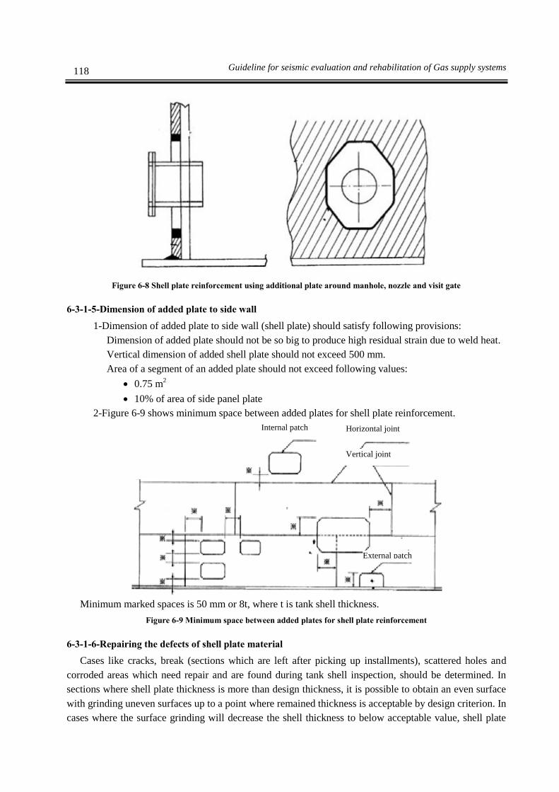
118 Guideline for seismic evaluation and rehabilitation of Gas supply systems
Figure 6-8 Shell plate reinforcement using additional plate around manhole, nozzle and visit gate
6-3-1-5-Dimension of added plate to side wall
1-Dimension of added plate to side wall (shell plate) should satisfy following provisions:
Dimension of added plate should not be so big to produce high residual strain due to weld heat.
Vertical dimension of added shell plate should not exceed 500 mm.
Area of a segment of an added plate should not exceed following values:
0.75 m2
10% of area of side panel plate
2-Figure 6-9 shows minimum space between added plates for shell plate reinforcement.
Minimum marked spaces is 50 mm or 8t, where t is tank shell thickness.
Figure 6-9 Minimum space between added plates for shell plate reinforcement
6-3-1-6-Repairing the defects of shell plate material
Cases like cracks, break (sections which are left after picking up installments), scattered holes and
corroded areas which need repair and are found during tank shell inspection, should be determined. In
sections where shell plate thickness is more than design thickness, it is possible to obtain an even surface
with grinding uneven surfaces up to a point where remained thickness is acceptable by design criterion. In
cases where the surface grinding will decrease the shell thickness to below acceptable value, shell plate
Internal patch Horizontal joint
Vertical joint
External patch

119 Chapter Six- Tanks retrofitting methods
should be repaired with repair weld and rest of the tests should be carried out. If a larger area of shell
plate needs repair, substituted shell plate with butt type weld or cover connecting plate should be used.
6-3-1-7-Replace of tank shells to change shell height
To increase tank shell height, it could be replaced with additional shells of new material. Modified
height of shell should be standard and all loads like wind and seismic loads should be considered.
6-3-1-8- Repair of shell inlets (manhole, nozzle, visit gate and etc.)
With this repair, reinforced plates are added to no reinforced nozzles. Reinforced plate should have all
requirements related to dimension and weld spacing of API STD 650.
6-3-2-Annular plates
1- Required thickness for annular plates should not exceed floor shell thickness.
2- Figure 6-10 shows methods for adding annular plate under tank floor shell.
3- Figure 6-11 shows external strengthening methods for annular plate.
6-3-2-1-Supporting plate
1-If compression stress under floor plate or annular plate under tank wall exceeds the limits,
supporting plate under floor plate or annular plate could be used to increase loading capacity
and stiffness of plates.
2-If compression stress transferred to top of foundation, exceeds allowable foundation bearing
stress, supporting plate could be added to top of foundation and beneath floor plate or annular
plate in order to decrease transferred stresses and increase tank shell stability.
3- Figure 6-12 show a sample of added supporting plate to top of foundation and beneath floor
plate or annular plate.
4- If compression stress beneath floor plate or annular plate beneath tank wall exceeds allowable
value, these plates will distort and cause rotation or plate displacement (figure 6-13). In these
cases supporting plate will increase plates' stiffness.
Figure 6-10 Methods for adding new annular plate under tank floor shell
Shell plate
Fillet welding
Annular plate Reinforcing annular
plate (new)
Shell plate
Fillet welding
Annular plate Reinforcing annular
plate (new) Fillet welding

120 Guideline for seismic evaluation and rehabilitation of Gas supply systems
Figure 6-11 outside strengthening of annular plates
Figure 6-12 Sample of added supporting plate
5- If compression stress transferred to top of foundation exceeds the limits, supporting plate could
be added to top of foundation and beneath floor plate or annular plate and decrease compression
stress in foundation and increase tank stability.
Figure 6-13 Supporting plate influence after seismic countermeasure
Fillet welding
Fillet
welding
Shell plate
Slop of drainage and isolating
materials
Annular plate
Beneath base plate

121 Chapter Six- Tanks retrofitting methods
Figure 6-14 Welding connections plates in tank floor
6-3-3-Floor plate
Following limitations should be considered for repair of floor plate of tanks with uniform supports by
use of welding plates:
1-Minimum plate dimension with weld connection which has overlaps between existing connection
and floor longitudinal gap is equal to 12 inch. Weld connection plate could be circle, four
cornered or multi cornered with rounded corners.

122 Guideline for seismic evaluation and rehabilitation of Gas supply systems
2-Weld connection plate smaller than 12 inch is allowed only when: its diameter is 6 inch or more,
has no overlaps with floor longitudinal gap, is not located partially or completely over existing
connection, if it has extended at least 2 inch more than floor corroded area.
3-Weld connection plates should not be located at portions of tank floor which has local or total
exfoliation. If tank settlement is still continuing, it is not recommended to attach weld
connection plate.
4-Weld connection plate is allowed to be used in mechanical dented or locally layered places if:
Dimension of unsupported sections in any direction does not exceed 300 mm, thickness is at
least 1/4 inch, minimum thickness is equal to existing floor thickness, longitudinal gaps does
not have overlaps with other connections, except for tanks which are designed according to API
Std 650, appendix M and weld connection plates should have minimum 3/8 inch thickness.
5-These repairs are permanent repairs and are subjects to inspection and maintenance plans.
6-3-3-1-Replacement of tank floor plates
1- Requirements for fixing replacement plate on floor plate are given in clauses (2) to (6).
2- Suitable and non corrosion shock absorbing materials like sand, gravel or concrete should be
used between previous and new floor.
3-Shell should be cut continuous and horizontal to tank floor. Cut edge should be able to drainage
all waste and particles produced during cut. As it is mentioned in API STD 650, new floor plate
should be continued to outside shell. All provisions related to weld spacing also should be
obeyed.
4- Void spaces inside foundation under old floor should be filled with sand, crushed lime stone,
mortar or concrete.
5- Except for allowed cases in clause (12) all inlets in the shell should be raised, or if new floor
level is not sufficient due to details of nozzle strengthening (refer to API 650, 3.7.2) or weld
spacing requirements are not observed according to Std 650, 3.7.3, then supporting plates
should be modified.
6-For tanks with floating roofs, new floor profile should keep roof level when it is located on its
supports. Floor level could be changed with changing support piers length. In order to keep the
main height above floor, it is possible to keep the support piers with their height or decrease
their height equal to new floor plate thickness plus deprecated thickness.
7- New base plates should be installed for supporting piers of floating roofs and fixed roofs. For
internal floating roofs with aluminum supports, new arsenic stainless metal or another
acceptable non metal separator (for example Teflon) should be used to separate supports from
carbon steel floors.
8-To separate shell from tank floor, one of the following methods will be used:
a) Cutting shell parallel to tank floor at least 50 mm above floor to shell weld
b) Separate all floor to shell weld including total penetration and heat effect area with proper
method like abrasion all arc shape areas of floor to shell weld should be tested with
magnetism particle and damaged areas should be repaired and tested again.
9- Installation of new floor after removing existing floor should be done according to API Std 650.
Except for cases mentioned in clause (12) existing inlets in shell should be raised or if new floor
level is not sufficient according to nozzle strengthening details (refer to API Std 650, 3.7.2) or
weld spacing requirements is not fulfilled according to API Std 650, 3.7.3, supporting plates

123 Chapter Six- Tanks retrofitting methods
should be modified. For tanks where shell plate stiffness is unknown, new welds in floor or
annular ring should be located in at least 3 inch distance or 5t, which ever is bigger from vertical
welds of floor shell. Here t is floor shell thickness in inch.
10- Replacing parts of existing tank floor (integrated rectangle plates or big plates) which are not
located in critical areas, will be done with provisions similar to provisions of installing new
floor in construction of new tanks according to API Std 650.
11-For tanks with cathodic protection and under floor leakage detection system, following items
should be considered:
a) In tanks with catholic protection under the floor, whole floor should be removed and old
shell will not be used for cathodic protection of new floor. Removal of old floor is important
for prevention of galvanic corrosion (refer to API REPAIR PLATE 651). If it is possible,
whole old floor except for unusable old shell and annular area with a diameter less than 18
inch of installed floor to shell should be removed.
b) Leakage detection system should be installed under the floor to direct the leakage to a place
which is visible from outside tank.
12- In tanks with material yield strength of 50000 lbf/in 2 or less if following conditions are met,
then it is not necessary to raise inlet pipes in shell:
a) For strengthened inlets including its lower type, there should be at least 100 mm between
weld toe to floor and the closest connecting weld toe of inlet. (Peripheral weld of support
plate or nozzle inlet weld to support plate of lower type and shell weld)
b) For self-supported inlets 3 inch or 2.5 t which ever is bigger should be kept between toe weld
of shell to floor and the closest toe weld of inlet.
c) Floor weld to shell should be done using low hydrogen electrodes and a welding guideline
which limits the distortion and residual stress should be used.
d) Toe of welds should be uniform to minimize the stress concentration.
i) For circular strengthening plates, uniforming of peripheral weld should be done from
4 o'clock position to 8 o'clock position. Grinding and uniforming of inside and outside
weld to floor should be done for at least for one length of penetration diameter on both
side of central penetration line.
ii) For diamond shape strengthening plates, lower horizontal length of diamond will be
grinded. Grinding of inside and outside shell weld to floor, should be done at least for
one penetration diameter length in both side of center line of penetration.
iii) For lower type inlets, uniforming of nozzle weld (support plate and shell) will be
done from 4 o'clock position to 8 o'clock position. Grinding of inside and outside shell
weld to floor, should be done at least for one penetration diameter length in both side of
center line of penetration.
e) Grinding length of clause D should be tested with magnetic particles, before and after
hydrostatic test.
13- Figure 2 (1) shows the gap limitation between added plate and floor support plate.

124 Guideline for seismic evaluation and rehabilitation of Gas supply systems
Figure 6-15 Gap limitation between added plate and floor support plate
14- If it become necessary to replace all floor plates, it is possible to enter the replacing plates from
the groove which is made on floor shell or from the inlet and locate it in its groove from inside
the tank. As it is shown in figure 60, when the new floor is installed in the groove, before
cutting the next groove, each plate should be welded in its location or should be supported
safely with upper part of shell plate. This will prevent shell buckling between grooves.
Peripheral layer should be from clean sand, metal mesh or a concrete layer should be installed
beneath the new layer with a minimum 76 mm distance from it so that the shell will reside over
the foundation and whole are of new floor. This method is called double floor method (API 575
9.2.3)
15- To replace floor in ordinary tanks using double floor method usually the segment beneath new
floor is not designed for strength and is not connected to new floor and that part of tank which is
located above. With increase of distance between previous and new floor majority of weight
could be exerted to resist against overturning moment. It is important to consider necessary
details to connect previous and new floors to each other with sufficient strength, because if the
tank faces uplift not only new floor and its contents but also old floor and separating materials
(usually concrete) should be moved. Concrete will increase floor section module and produce
stiffness and will decrease the uplift. Again the soil supporting pressure should be controlled.
This method will decrease the effective tank capacity because the new floor should be located at
least 76mm (in special cases 300 mm) above the old floor to be effective.
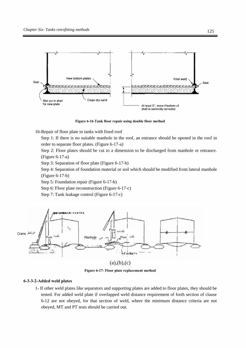
125 Chapter Six- Tanks retrofitting methods
Figure 6-16 Tank floor repair using double floor method
16-Repair of floor plate in tanks with fixed roof
Step 1: If there is no suitable manhole in the roof, an entrance should be opened in the roof in
order to separate floor plates. (Figure 6-17-a)
Step 2: Floor plates should be cut to a dimension to be discharged from manhole or entrance.
(Figure 6-17-a)
Step 3: Separation of floor plate (Figure 6-17-b)
Step 4: Separation of foundation material or soil which should be modified from lateral manhole
(Figure 6-17-b)
Step 5: Foundation repair (Figure 6-17-b)
Step 6: Floor plate reconstruction (Figure 6-17-c)
Step 7: Tank leakage control (Figure 6-17-c)
(a),(b),(c)
Figure 6-17- Floor plate replacement method
6-3-3-2-Added weld plates
1- If other weld plates like separators and supporting plates are added to floor plates, they should be
tested. For added weld plate if overlapped weld distance requirement of forth section of clause
6-12 are not obeyed, for that section of weld, where the minimum distance criteria are not
obeyed, MT and PT tests should be carried out.
Plate
Plate Plate Crane
Manhole

126 Guideline for seismic evaluation and rehabilitation of Gas supply systems
2- Those weld plates which are located in critical regions, should be installed according to all
requirements.
6-3-4-Foundation
On-ground tanks will sit on compacted soil foundations or annular concrete walls or mats or a
combination of them. Those tanks which are directly on the ground will sit on sand, gravel, asphalt, or
crushed stone layer. Anchoring these tanks is difficult. There are three methods to anchor tanks with soil
foundation.
i) In small and medium tanks, they should be lifted and construct a new foundation beneath them
or build a new foundation with excavating the peripheral of the tank. In this method, anchoring
bolt should be located in new foundation and anchors of retrofitted concrete should not be used.
It is not necessary that soil bears the uplift forces like the foundation and anchorage are installed
for this purpose. Allowed stresses should be controlled for earthquake and also anchoring loads
like foundation ordinary design. Figures 6-18 and 6-19 show the method to lift the tank using
jacks to repair the foundation settlement. Steps are as follows:
Step 1: Plating for jack (figure 6-18-a)
Step 2: Deformed floor plate will be removed using proper wires (figure 6-18-b)
Step 3: Lifting tank (figure 6-18-b)
Step 4: Repair of foundation settlement (figure 6-18-b)
Step 5: Locating flat floor plate on repaired foundation (figure 6-18-c)
Figure 6-18-a-b-c Lifting all tank using jacks to repair foundation settlement
Jack
Supporting
cable
Bracket
Supporting
cable

127 Chapter Six- Tanks retrofitting methods
Figure 6-19 Lifted tank to repair below layer
ii) Moving bigger tanks without damage is more difficult and costs more.
Although it provides retrofitting of annular wall beneath tank shell.
In most case annular wall weight is not enough against uplifting force.
Spiral piles and caissons are necessary for retrofitting.
Figures 6-20 and 6-21 show two methods for reinforcement of tank foundation (annular
wall)
Seismic retrofitting will be done in connections by replacing tank floor.
Floor replace will increase weight and therefore increase the resistance against uplift.
Figure 7-20 Reinforcement method of tank foundation
Tank
Asphalt
Tank
concrete
Pressure line
Seismic countermeasure for external tanks

128 Guideline for seismic evaluation and rehabilitation of Gas supply systems
Figure 6-21 Reinforcement method of tank foundation
6-3-4-1-Slabs
Tanks with slabs beneath them need the minimum retrofitting.
Foundation without retrofitting does not have strength on toppling forces and should be controlled.
Tank could be anchored directly to slab but if there is not enough space between bolt and slab edge,
the foundation should be extended in radial direction to accommodate anchorage bolts.
In thin slabs, the bolts should pass through the slab. In this case, washers or plates will be used beneath
the slab to spread the bolt force in a wider area.
With all retrofitting, soil bearing capacity should be checked and approved for seismic toppling forces.
Otherwise foundation may need other sort of retrofitting.
6-3-4-2-Annular walls
1-When a tank is anchored to annular walls, it should be designed for additional seismic forces,
namely shear and moment due to anchorage.
2-Annular wall will be modeled as a continuous beam with supports on piles location.
3-Depending on location of annular wall and load direction, the moment could be positive or
negative.
4-Load direction could be the tensile forces of bolts or compression stress from tank shell.
5-Eccentricity between bolts and piles could produce torsion in annular walls which should be
considered in the design.
6-Piles should have connections to resists uplift due to uplift forces produced by seismic loads.
7-Piles added beneath the annular wall will take bigger portion of vertical loads comparing to
center of tank which is sat on the soil.
8-If soil settlement continues, differential settlement between annular wall and tank center should
be calculated.
9-For tanks with annular wall, the anchorage system will be connected to shell and shell will be
anchored to annular wall. It may be necessary to improve annular wall against toppling forces.
Tank
Asphalt Tank
concrete
Seismic countermeasure for external tanks

129 Chapter Six- Tanks retrofitting methods
10-One method of retrofitting is to extend the annular wall in radial direction and increase weight.
11-Usually it will become necessary to increase number of spiral piles and caissons.
6-3-4-3-Piles
1-In this section basic data will be given on spiral piles and will be compared with other types of
piles but detailed design will not be covered. In order to resist against earthquake, tank should
be able to transfer seismic forces to soil. Usually earthquake causes tank to uplift in a part of
foundation and having piles in those area could produce sufficient strength against tension.
Following piles can resist against tension forces:
Driven piles
Caissons (or drilled shaft foundations, deep piers)
Spiral piles
2- Spiral plies are the best ones due to economical reasons. Spiral piles are big plates which twisted
around the shaft in spiral manner. Usually they are put in their place with rotation. Equipments
used for installing these pile are smaller comparing to other type of piles and usually they are
put on trucks.
3- Resistance against pull out will be supplied by soil itself and in shallow soils damage in shear
cone will occur from spiral plate upward. Less than 5 cycle of rotation of spiral plate is
considered as shallow soil and more than that is deep soil. In deep soils damage surface is
anchorage diameter. It is better to use deep anchoring system because has flexible damage
mode. Anchorage diameter is between 8 to 14 inch. Spiral pile will be inside the foundation and
therefore no pullout will take place. Figure 6-22 shows a sample of spiral pile. Its plate and
concrete should be checked for following items:
Support pressure of concrete beneath the plate
Shear and bending stress in plate
Pullout of support plate from concrete
4-When the spiral pile could be in tension or compression, all above three items should be checked
in both directions.
5-When pile can not be anchored to rock, soil depth should be considered deep (five times
diameter). When the spiral piles are fixed in their place, soil should not be highly compacted nor
has big rocks.
6-Spacing considerations should be applied:
Minimum spacing between piles is three times the diameter.
Minimum spacing between adjacent structures is five times the diameter.
7- If it is impossible to impose above-mentioned limitations, other types of piles should be used.
8- Spiral piles' cost is less than caisson, but soil condition could be the main factor for economical
selection.
9-It is necessary to investigate the under tank soil condition to ensure the safety of anchors.
10- Spiral pile age should be considered with estimated corrosion rate. It is possible to use cathodic
protection system to extend the spiral anchor's age or select big enough anchors to pass the
allowed corrosion limit.
11-If the soil is shallow or has low strength it might not resists pullout. In these cases it is
economical to use piles or caisson and combination of seismic anchorage and floor replacement
should be applied. In this method, tank's own weight will be used for anchoring and it could be

130 Guideline for seismic evaluation and rehabilitation of Gas supply systems
applied for all types of foundation when soil loads are less than allowed loads. It might not be
the best economical choice.

131 Chapter Six- Tanks retrofitting methods
Figure 6-22 Spiral piles used with annular wall foundation
6-3-4-4-Drainage of rain water beneath the foundation
After retrofitting of foundation, annular wall, slab, annular plate & floor plate the upper part of rain
water drainage should be protected with proper seal. Figure 6-24 shows the protection of rain water
drainage using seals.
Figure 6-24 Protection of rain water drainage using seals
Tank floor
Vertical bolt
Stirrup
1 inch chamfer
3 equal space
A307 1"Φ
Spiral pile
#4 stirrups
Slope
Tank wall
Bolt with washer and
nut
Bolt CL
Pile CL
Bolt support
Compacted drainage material
Tank inside
Annular plate
Concrete ring
Asphalt
Concrete block
Ground level
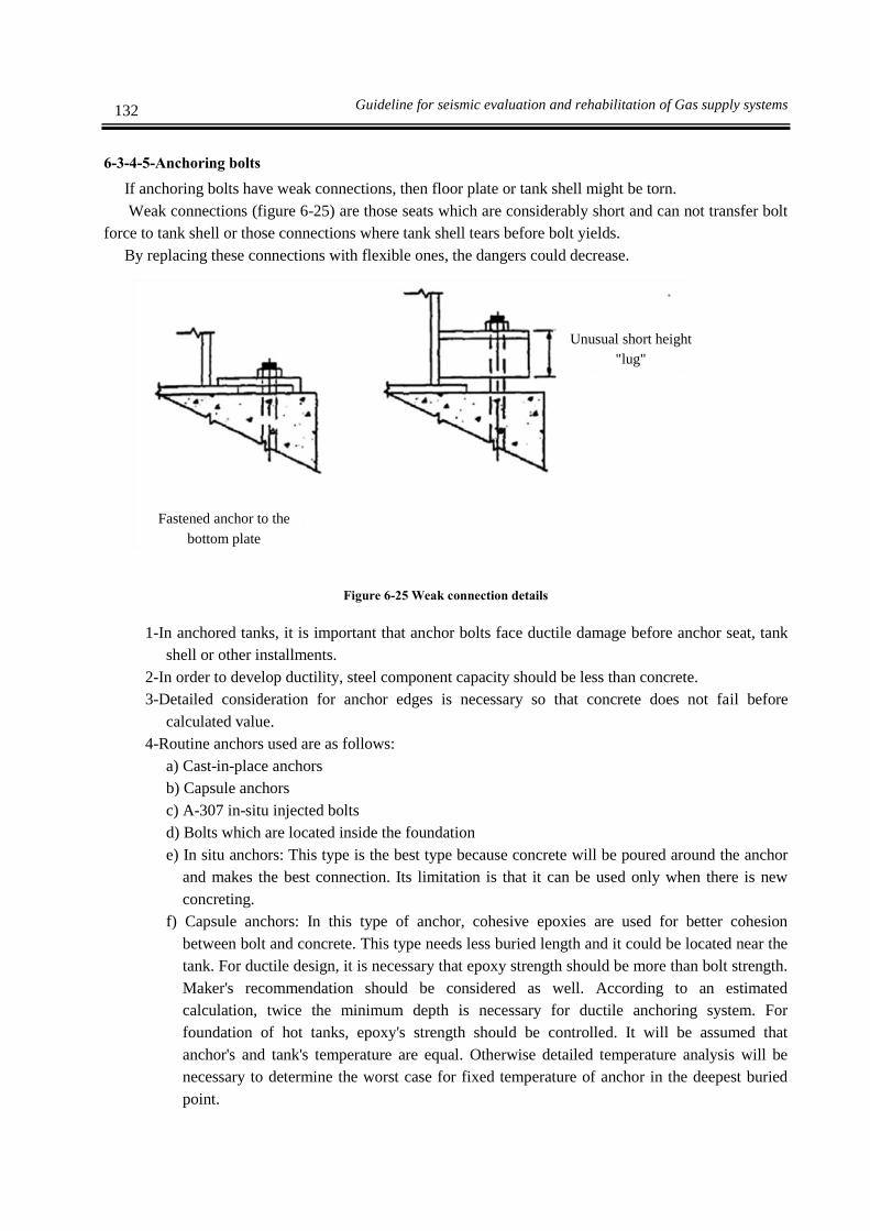
132 Guideline for seismic evaluation and rehabilitation of Gas supply systems
6-3-4-5-Anchoring bolts
If anchoring bolts have weak connections, then floor plate or tank shell might be torn.
Weak connections (figure 6-25) are those seats which are considerably short and can not transfer bolt
force to tank shell or those connections where tank shell tears before bolt yields.
By replacing these connections with flexible ones, the dangers could decrease.
Figure 6-25 Weak connection details
1-In anchored tanks, it is important that anchor bolts face ductile damage before anchor seat, tank
shell or other installments.
2-In order to develop ductility, steel component capacity should be less than concrete.
3-Detailed consideration for anchor edges is necessary so that concrete does not fail before
calculated value.
4-Routine anchors used are as follows:
a) Cast-in-place anchors
b) Capsule anchors
c) A-307 in-situ injected bolts
d) Bolts which are located inside the foundation
e) In situ anchors: This type is the best type because concrete will be poured around the anchor
and makes the best connection. Its limitation is that it can be used only when there is new
concreting.
f) Capsule anchors: In this type of anchor, cohesive epoxies are used for better cohesion
between bolt and concrete. This type needs less buried length and it could be located near the
tank. For ductile design, it is necessary that epoxy strength should be more than bolt strength.
Maker's recommendation should be considered as well. According to an estimated
calculation, twice the minimum depth is necessary for ductile anchoring system. For
foundation of hot tanks, epoxy's strength should be controlled. It will be assumed that
anchor's and tank's temperature are equal. Otherwise detailed temperature analysis will be
necessary to determine the worst case for fixed temperature of anchor in the deepest buried
point.
Fastened anchor to the
bottom plate
Unusual short height
"lug"

133 Chapter Six- Tanks retrofitting methods
g) A-307 injected bolts: When the above-mentioned conditions regarding spacing and distance
from edge are not possible, this type of bolts will be used. The advantage of these bolts are as
follows:
Short distance from edge is required.
Bolts could be placed in minimum depth of concrete.
Disadvantages are as follows:
Bigger eccentricity will occur as they need bigger holes.
They need bigger safety factor because of bigger ductility of concrete cone
h) Steel bolts: For those slabs and foundations which are not thick, those anchors could be used
where they can penetrate in foundation. Stainless steel bolt is recommended when there is the
possibility of corrosion to carbon steel bolts.
6-4-Attached equipments
One ordinary failure mode in tanks is the break of pipeline attached to tank due to relative movement
between tank and nearest pipe support. If piping is stronger than tank wall or support plate which is
connected to, then wall or support plate will break. Piping should never go directly or with less or no
flexibility through shell, floor, concrete walls, pool and pumps which are connected rigidly to ground.
Different types of damages explained above, are shown in figures 6-26(a) to 6-26(d) in detail.
In the first three cases pipeline flexibility should be provided using additional vertical and horizontal
bends or attaching a flexible pipeline.
In four cases, piping should connect to tank center or if piping is flexible enough, concrete pool could
be extended up to connection of pipe to tank.
1- As it is shown in figure 6-26 (E) damages are due to relative movement of two tanks connected
by a rigid pipe. Piping flexibility as explained above should be applied.
2- Where the vertical pipe is connected rigidly to ground or foundation, and also it is fixed rigidly
to wall of tank, minor damages as shown in figure 6-26 (F) may occur.
3- The case which has less risk but occurs frequently. is the support of wall tank and it has a big U-
shaped bolt and has the freedom to move the pipe with tank upward and downward. It is
possible that U-shaped bolt fixes to pipe and produce a rigid connection and cause the tear off of
tank wall.
4- All rigid connections along the tank shell should be replaced with a connection close to
intersection of shell and roof or connected to sliding connections or guides along the shell wall.
In most cases it is sufficient to loose the nuts of U-shaped bolt.
5- Access to roof is possible through walkways located between tanks spans. A sample for
walkways plans is shown in figure 70(G).
6- In both cases, relative movement between tanks may cause break or tear off of wall or roof. In
lower walkways shown in figure 6-26(G) there might be minor damage to tank content. In upper
walkways in the worst case it might damage the walkway itself or roof and therefore there will
be no damage to tank content. The difference between two walkways is important because the
lower walkway could cause the release of tank content but damage of upper walkway only
releases the vapors and produces less economical damages. In both cases it is necessary to
increase the flexibility of walkways.

134 Guideline for seismic evaluation and rehabilitation of Gas supply systems
Also for tall tanks located in a crowded site and with high precision instruments, there is the risk of
overturning. Walkways should be fixed by a secondary element like cable to tank in order to prevent its
fall.
1-Stairs should not be connected both to foundation and tank shell (refer to figure 6-26(H)).
Although in tanks with thin shells, these details may cause tank wall damages and damage to
tank content. Therefore this case should be studied separately from tanks with thick shell
because in the latter one, these details only cause damage to stairs itself. In both cases, it is
possible to decrease the risk by connecting the stairs to tank shell or use other connections to
decrease the vertical displacement of stairs.
2-As it is shown in figure 6-26 (I), tank piping is concentrated in one area and in-between
walkways are supplied to access pipelines.
3-If walkway is fixed to ground rigidly and there is no enough space between piping and walkway,
tank uplift might cause collision between piping and walkway and damage one of them.
4-In piping with small diameter or tanks with thin shell, tank content might damage as well.
Otherwise damages will be limited to walkway itself. In both cases, by increasing pipeline
flexibility, it is possible to decrease the damage risk. As it is mentioned in item (5) for stairs,
another detail which has high seismic vulnerability is the case where walkway is attached to
tank and foundation.

135 Chapter Six- Tanks retrofitting methods
Weak details Retrofitting method
A
Adding flexible pipe
B
Adding flexible pipe
C
Adding flexible pipe
D
Connection of
piping to tank
center or extension
of concrete pool
wall up to pipe- tank
connection
E
Increase flexibility
or use of horizontal
and vertical bends
Piping
Tank shell
Tank
shell
Piping
Concrete pool
Tank shell
Piping
Concrete pool
Tank shell
Piping
Variable length from one
foot
up to tank height
Tank shell
Pipe
Concrete wall Tank shell
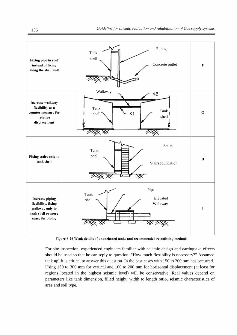
136 Guideline for seismic evaluation and rehabilitation of Gas supply systems
F
Fixing pipe in roof
instead of fixing
along the shell wall
G
Increase walkway
flexibility as a
counter measure for
relative
displacement
H
Fixing stairs only to
tank shell
I
Increase piping
flexibility, fixing
walkway only to
tank shell or more
space for piping
Figure 6-26 Weak details of unanchored tanks and recommended retrofitting methods
For site inspection, experienced engineers familiar with seismic design and earthquake effects
should be used so that he can reply to question: "How much flexibility is necessary?" Assumed
tank uplift is critical to answer this question. In the past cases with 150 to 200 mm has occurred.
Using 150 to 300 mm for vertical and 100 to 200 mm for horizontal displacement (at least for
regions located in the highest seismic level) will be conservative. Real values depend on
parameters like tank dimension, filled height, width to length ratio, seismic characteristics of
area and soil type.
Pipe
Tank
shell Elevated
Walkway
Stairs
Tank
shell
Stairs foundation
Walkway
Tank
shell
Tank
shell
Piping
Concrete outlet
Tank
shell
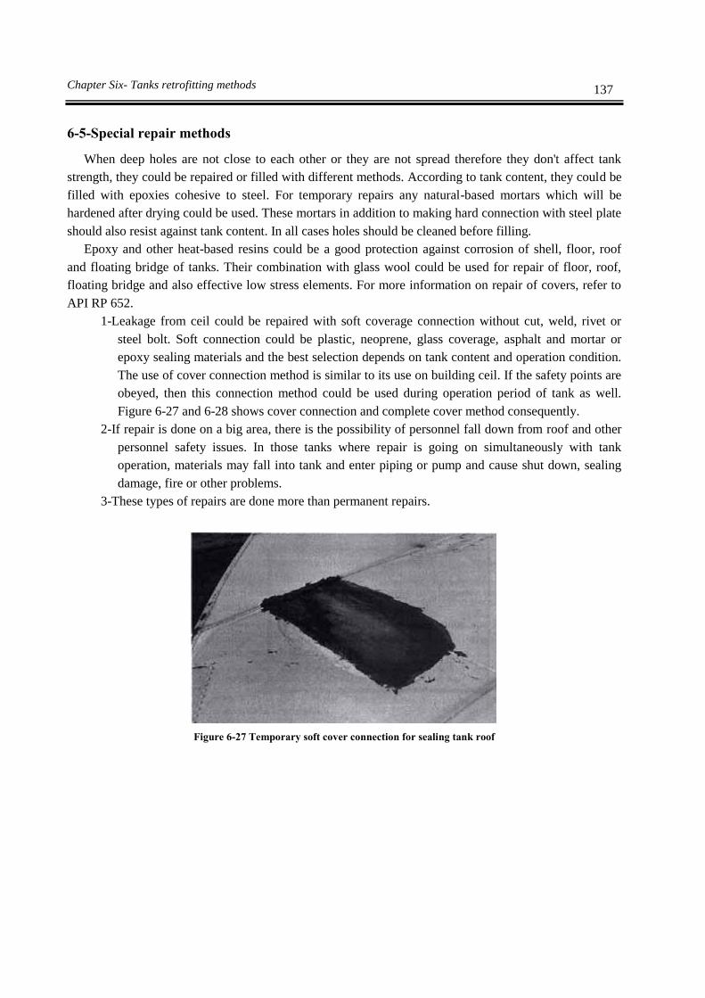
137 Chapter Six- Tanks retrofitting methods
6-5-Special repair methods
When deep holes are not close to each other or they are not spread therefore they don't affect tank
strength, they could be repaired or filled with different methods. According to tank content, they could be
filled with epoxies cohesive to steel. For temporary repairs any natural-based mortars which will be
hardened after drying could be used. These mortars in addition to making hard connection with steel plate
should also resist against tank content. In all cases holes should be cleaned before filling.
Epoxy and other heat-based resins could be a good protection against corrosion of shell, floor, roof
and floating bridge of tanks. Their combination with glass wool could be used for repair of floor, roof,
floating bridge and also effective low stress elements. For more information on repair of covers, refer to
API RP 652.
1-Leakage from ceil could be repaired with soft coverage connection without cut, weld, rivet or
steel bolt. Soft connection could be plastic, neoprene, glass coverage, asphalt and mortar or
epoxy sealing materials and the best selection depends on tank content and operation condition.
The use of cover connection method is similar to its use on building ceil. If the safety points are
obeyed, then this connection method could be used during operation period of tank as well.
Figure 6-27 and 6-28 shows cover connection and complete cover method consequently.
2-If repair is done on a big area, there is the possibility of personnel fall down from roof and other
personnel safety issues. In those tanks where repair is going on simultaneously with tank
operation, materials may fall into tank and enter piping or pump and cause shut down, sealing
damage, fire or other problems.
3-These types of repairs are done more than permanent repairs.
Figure 6-27 Temporary soft cover connection for sealing tank roof
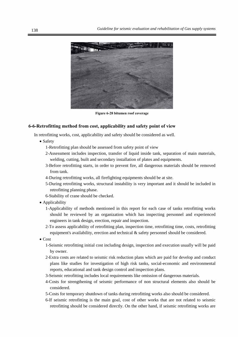
138 Guideline for seismic evaluation and rehabilitation of Gas supply systems
Figure 6-28 bitumen roof coverage
6-6-Retrofitting method from cost, applicability and safety point of view
In retrofitting works, cost, applicability and safety should be considered as well.
Safety
1-Retrofitting plan should be assessed from safety point of view
2-Assessment includes inspection, transfer of liquid inside tank, separation of main materials,
welding, cutting, built and secondary installation of plates and equipments.
3-Before retrofitting starts, in order to prevent fire, all dangerous materials should be removed
from tank.
4-During retrofitting works, all firefighting equipments should be at site.
5-During retrofitting works, structural instability is very important and it should be included in
retrofitting planning phase.
6-Stability of crane should be checked.
Applicability
1-Applicability of methods mentioned in this report for each case of tanks retrofitting works
should be reviewed by an organization which has inspecting personnel and experienced
engineers in tank design, erection, repair and inspection.
2-To assess applicability of retrofitting plan, inspection time, retrofitting time, costs, retrofitting
equipment's availability, erection and technical & safety personnel should be considered.
Cost
1-Seismic retrofitting initial cost including design, inspection and execution usually will be paid
by owner.
2-Extra costs are related to seismic risk reduction plans which are paid for develop and conduct
plans like studies for investigation of high risk tanks, social-economic and environmental
reports, educational and tank design control and inspection plans.
3-Seismic retrofitting includes local requirements like omission of dangerous materials.
4-Costs for strengthening of seismic performance of non structural elements also should be
considered.
5-Costs for temporary shutdown of tanks during retrofitting works also should be considered.
6-If seismic retrofitting is the main goal, cost of other works that are not related to seismic
retrofitting should be considered directly. On the other hand, if seismic retrofitting works are

139 Chapter Six- Tanks retrofitting methods
the main goal and it needs non seismic works as well, then these works should not be
considered as seismic retrofitting.
7-If seismic retrofitting budget decreases, then the political and social costs might not be
considered. Unfortunately in seismic retrofitting, there is a need for omission of vulnerable
parts of structure of tank in most of the time.
8-Internal inspection costs: These costs are very important and could reach as much as millions
of dollars for a petroleum company. Most of these costs are related to tank preparation for
internal inspection and stop of operation. In this report and API Std 653 some methods have
been introduced to lengthen the internal inspection period from few years to 20 years.
9-Costs according to findings of inspection: During assessment of operation there is a chance to
conserve costs. For example a tank which has many deficiencies according to standards,
could assessed to be updated without considering costs. Results of this assessment will tell us
what works are necessary to be done to update tank and enhance its operation. Cost
difference of these two methods could be considerable.
10-Cost of keeping information: Establish and keep a data collection system. One of the data
collection system's goals is to reduce total cost of owner or operator through standardization
and development.
6-7-Miscellaneous activities
Roof, shell and floor plates could be cut to small pieces and transferred to a new site for
reconstruction.
6-7-1-Floors
1- Those floor plates which will be used again, should be cut at least in 2inch distance from
previous welds except for sections where cuts will cross the weld strips.
2- If floor is useable, then one of the following methods is acceptable:
a) Floor plate could be separated from shell along the A-A and B-B line as shown in figure 6-
29, and floor plate & grinded welds are connected directly to shell.
b) If all plates of floor are used again, then floor will be cut along the C-C line and separated
from shell.
c) If tank has annular ring with butt weld, this ring could remain connected to shell or cut along
the B-B line or otherwise annular ring weld will be separated from shell.

140 Guideline for seismic evaluation and rehabilitation of Gas supply systems
Figure 6-29 Cut line of floor and shell
6-7-2-Shells
1-Tank shell plates could be separated with one of the following methods:
a) All shell rings could be separated by cutting weld strip and heat affected zone (HAZ) of weld.
Minimum HAZ value is the smallest value of 0.5 times the width of weld iron or one forth of
inch in both side of weld.
b) If the thickness of shell ring is 1/2 inch or less, then it could be separated by weld cut without
HAZ.
c) Shell rings could be separated with horizontal and/or vertical cuts in at least 6 inch distance
from existing welds except for areas where cut lines cross existing weld.
2- Stiffening rings of shell including bracings could remain connected to shell plates or could be
separated by cutting the connecting welds.
3- As it is seen from figure 6-29, floor plate connection to shell should be cut along B-B line. Floor
weld to shell should not be used again except if whole floor is intact and will be used again.
6-7-3-Roofs
1- Roof plates should be cut using welding or cut along remaining welds in at least 5 mm distance
from existing cut welds except for areas where cut lines cross welds.
2- Roof supporting structure should be separated by removing bolts or removing welds.
Bottom plate
Shell

Chapter 7
Retrofitting of on ground
pipelines


143 Chapter Seven- Retrofitting of on ground pipelines
7-1-Target components
Main pipelines or transmission pipelines include pipes, valves and connections between pump room
outlet main block valve and terminal input main line block valve.
On ground pipelines are divided into two categories depending on installation conditions.
1-On ground pipelines: On ground pipelines and its supports should be studied for corrosion,
mechanical integrity, stability and aging of support's concrete.
2-On ground transmission pipelines: On ground pipelines should be studied for corrosion,
mechanical integrity, ground stability. Inspection and periodic maintenance is necessary along
the pipeline to prevent human losses.
3-Pipe bridges: Pipe-bridge will be used when it is impossible to pass underground and it will be
used in junctions with natural barriers or roads. Pipe bridges should be designed according to
structural standards with sufficient free gap to avoid probable damages due to traffic and access
for repair and maintenance.
Interfere between catholic protection of pipeline and bridge structure should be considered.
7-2-Damage modes due to earthquake
Seismic risk which will effect on ground pipelines and bridges are as follows:
a) Fault movement
Pipeline which crosses fault will deform due to permanent ground displacement (PGD) and
produces different damage modes like buckling due to compression force, tearing due to tension
and shear failure.
b) Liquefaction risk
Liquefaction in sandy soils with high underground water level, especially in modified areas will
cause large-scale ground displacement.
Lateral spread or settlement will cause severe damages to on ground structures.
c) Landslide
Landslides usually occur in steep slopes. In this case, if monitoring equipments are installed
along the pipeline, they will be damaged.
Figure 7-1 Cracks and buckling in bent pipe
d) Pipe bridges

144 Guideline for seismic evaluation and rehabilitation of Gas supply systems
When the pier moves or rotates due to earthquake, it will damage not only the super structure
but also the attached pipeline. Pier damage is due to large- scale ground displacement like
liquefaction, fault movement and landslide. Following figure shows damage to bridge pier due
to liquefaction. Pipeline has suffered considerable damages as well.
Figure 7-2 Damage to pipeline due to failure of bridge in spread liquefaction
According to above items, damage modes to pipeline are as follows:
1-Severe damage mode
Severe damage mode for a pipeline system is defined as a pipe in plastic state or ultimate limit with
large movement or displacement and threats integrity of the pipeline.
2-Medium damage mode
Medium damage mode for a pipeline system is defined as a pipe in plastic state with considerable
displacement and threats integrity of the pipeline but still operable.
3- Minor damage mode
Minor damage mode for a pipeline system is defined as a local damage with limited
displacement and no threats to integrity of the pipeline.
Damage modes for each structural element are given in table 7-1. Damage mode for
performance of each related element is also given in table 7-2.
Table 7-1 Damage modes from structural damage point of view
Structure Elements Structural damage modes
Minor Medium Severe
Structure
On ground pipeline Minor damage Case damage Tear
Pipe bridge Small
movement Relative displacement Collapse
Pipe on bridge Small
movement Large- scale displacement Break
Pier Ignorable crack Minor damages Downfall
Valve Small
movement Considerable movement Break
Monitoring tools Small
movement Considerable movement Break
Protection equipments against Small Considerable movement Break

145 Chapter Seven- Retrofitting of on ground pipelines
corrosion movement
Pipe connected to structural facilities Small
movement Considerable movement Break
Transmission pipeline Small damage Damages in specific
length Tear
Pipeline
system
Control center Small damage Considerable damage Downfall
Terminal facilities Small damage Considerable damage Downfall
Table 7-2 Damage modes from performance point of view
Structure Elements Structural damage modes
Minor Medium Severe
Structure
On ground pipeline Small settlement Bearable settlement Large- scale
settlement
Pipe bridge Low hydraulic
turbulence in transfer
Considerable hydraulic
turbulence in transfer Stop working
Pipe on bridge Small settlement Bearable settlement Large- scale
settlement
Pier Low hydraulic
turbulence in transfer
Considerable hydraulic
turbulence in transfer Stop working
Valve Almost intact Usable but it should be
controlled later
Defected &
unusable
Monitoring tools Almost intact Usable but it should be
controlled later
Defected &
unusable
Protection equipments
against corrosion Almost intact
Usable but it should be
controlled later
Defected &
unusable
Pipe connected to
structural facilities Small settlement Bearable settlement
Large- scale
settlement
Transmission pipeline Possible to operate
with caution
Transmission with low
pressure Stop working
Pipeline
system
Control center Possible to operate
with caution Defect in part of system
Defected and
unusable
Terminal facilities Possible to operate
with caution Defect in part of system
Defected and
unusable
Those seismic levels which will be used like effects of seismic wave and ground permanent
displacements should be categorized for risk assessment of pipeline system in damage modes as
shown in table 7-3

146 Guideline for seismic evaluation and rehabilitation of Gas supply systems
Table 7-3 Seismic levels which are used for each damage mode
Earthquake Damage modes
Minor Medium Severe
Wave effects Risk level 1 o x x
Permanent ground
displacements
Risk level 2 x o o
Fault movement x o o
Lateral spread due
to liquefaction x o o
Settlement due
to liquefaction x o o
Landslide x o o
7-3-Seismic assessment procedure
Seismic retrofitting and assessment steps for pipeline system are explained below and related
flowcharts are shown in figures 7-3 and 7-4.
Step 1: Initial assessment
Step 2: Detailed assessment
Step 3: Presenting seismic retrofitting plan
Step 4: Check the adequacy of seismic retrofitting
Figure 7-3 shows few criteria for seismic retrofitting based on results of assessed inspection and figure
7-4 shows the inspection procedure and discussion about the necessity of first and second assessment and
seismic assessment respectively.
1- Initial assessment
General and fast study of seismic performance of pipeline system should be done by walking
along the line. This inspection is done to show the need for detailed assessment. Group or
individual inspections should be prior to control inspection activities according to importance of
existing pipeline system.
2-Detailed assessment
Target pipeline and its seismic performance should be selected and approved by client in the
first step of detailed seismic assessment.

147 Chapter Seven- Retrofitting of on ground pipelines
Initial evaluation
Local walking inspection
Second evaluation
Detailed inspection
Start
Does it need retrofitting or
renewal?
Assessment report
Retrofitting or renewal
Repair Renewal
Priority
Cost
Time
Retrofitting & assessment reportEnd
Yes
No
Figure 7-3 Seismic assessment flowchart for on ground pipeline and pipe bridge
3- Presenting seismic retrofitting plan
Based on detailed assessment report, proper seismic retrofitting measures for structural elements
will be chosen in sequential order. If renewal measures are chosen, precise study on priority,
time and cost should be done.
4- Control the adequacy of seismic retrofitting plan
Adequate control should be done on the adequacy of selected seismic retrofitting plan before
execution.

148 Guideline for seismic evaluation and rehabilitation of Gas supply systems
Start of inspection
End of inspection
Importance of facilities is more?No
Preparation of requested documents
Sample
inspection
Initial evaluation
Full inspection
Need for secondary assessment?
Should detailed quality
inspection be done?
YesNo
Detailed
inspection
Standard
inspection
Detection of damage
conditions
Internal
inspection
External
inspection
Assessment with standard
criteria
Allowed stress analysis
Precise strain &
displacement analysis
Does the pipeline have seismic
performance?
Does the pipeline have seismic
performance?
End of inspection
Retrofitting
Simplified non elastic
analysis MCE
MOEAllowed stress analysis
Assessment with standard
criteria
Detection of damage
conditions
No
YesYes
Yes
Figure 7-4 Seismic inspection flowchart for on ground pipeline and pipe bridge
7-4-Retrofitting
7-4-1-Prioritizing of retrofitting
Prioritizing retrofitting measures is based on following items:
1- To minimize live loss due to earthquake
2- Selection of pipeline in an area with the highest seismic risk
3- To minimize the social damages

149 Chapter Seven- Retrofitting of on ground pipelines
4- Selection of the most important pipeline from risk and financial point of view
7-4-2-List of possible methods
Three methods are recommended for retrofitting as follows:
1- Retrofitting based on the result of inspection: Although the local inspection results are not
adequate, but it is possible to use them to solve many defects in pipeline and related facilities.
There are many ways for this method in pipeline system and some of them are shown in figure
7-4.
2- Retrofitting based on detailed assessment: It is possible to obtain more precise and reliable
results in detailed assessment. In this step, based on reports, if leakage risk or damage and
structural aging are diagnosed, the damaged part should be repaired or replaced rapidly.
3- Retrofitting based on repair and maintenance methods for pipeline system: These methods
include following items:
a) On ground pipeline and pipeline bridge
b) Shut off valve
c) Control valve
In table 7-5 examples of these retrofitting methods are given. Some of these methods are shown in
figures 7-5 to 7-7 as sample.
Table 7-4 Protection methods against leakage for different damage modes
Retrofitting methods
for protection
against leakage
Crack &
break corrosion
Loosening of
connection
Pipe Weld
Connection Mechanical connection of flexible cast iron
Flange
connection
Replace ○ ○ ○ ○ ○
Piping insert ○ ○ ○ ○ ○
Rep
air
of
con
nec
tio
n Steel plate coverage ○
Replace washer ○ ○
External coverage ○ ○
Internal coverage ○ ○ ○ ○
Catholic protection ○
Note ○: is applicable

150 Guideline for seismic evaluation and rehabilitation of Gas supply systems
Table 7-5 Retrofitting method for pipeline system
Location Defect Retrofitting measures
On ground pipe
Leakage Repair or replace depending on conditions
Damage or aging of cover and
anti corrosion materials Repair
Expansion
connection Leakage & aging Replace or installing additional expansion connection
Pipe's support
structure
Non fixed or loose anchoring
rods Repair
Instability of fixed pipes Repair or replace
Support
equipment Crack, damage in equipment Repair or replace
Pipe inside wall Isolation performance Repair
Pipe under wall Settlement Control of pipeline settlement, after that if it becomes
necessary, reduce stress and replace pipe
Figure 7-5 U-shaped bolt Figure 7-6 Anchoring steel pipe
Figure 7-7 Solid frame as a seismic lateral support

151 Chapter Seven- Retrofitting of on ground pipelines
Table 7-6 Retrofitting method for shut off valve
Location defect Retrofitting measures
shut off valve leakage
1. Tighten of flange screw to stop the
leakage
2. Repairing or replacement of valve body if
it leaks
handle Capacity of operating
1. oiling of handle
2. if necessary, separating and installing or
replacing
Inside the hole Waterproof performance 1. cleaning
2. if necessary, repair for waterproofing
Hole cover Manhole cover closing
performance
cleaning of connection part
2. if necessary, replacement after temporary
repairing
Space between hole cover and road
surface Settlement Alignment of manhole surface to road level
Table 7-7 Retrofitting method for control valve
Location Reasons Retrofitting measures
Pressure increase in pier
(1) weakness in valve body Repair of damaged parts or adjusting
installing conditions for main valve
(2) Inadequate closure of lateral
line
Complete closure of lateral line
(3) improper performance of
pipeline
Replace damaged parts
Pressure decrease in pier
(1) improper performance of
control equipments
Replace damaged parts
(2) improper performance of
secondary pipeline
Cleaning secondary pipeline
(3) pressure drop Replace equipments, cleaning dust
(4) closure by shut off valve Opening shut off valve and inspect the reason
for improper performance
Secondary effects due to big
variation of pressure
(1) improper performance of
control equipments
Replace damaged parts
(2) Rapid change in pressure Replace main valve with rapid response
capability valve
(3) Unbalance in flow pressure Repair or replace of damaged parts
(4) Short flow Replace new valve with proper performance
Leakage
(1) Inadequate cover for
connection part
Fastening or replace of bolts
(2) improper performance of
damage alarm system
Control installation conditions or replace it

152 Guideline for seismic evaluation and rehabilitation of Gas supply systems
7-4-3-Determine retrofitting method from safety, applicability and cost point of view
In pipelines, damage due to leakage in large scales should be avoided. It is not only natural hazards
which cause considerable damages to pipeline and finally lead to leakage, but also human activities may
cause this problem. The most usual reasons for damages include human threats, corrosion and aging
effects, inadequate care of connecting bolts and finally damages due to earthquake. In table, 7-8
retrofitting methods for leakage due to different reasons are compared. Each method is studied from
safety, applicability and cost point of view.
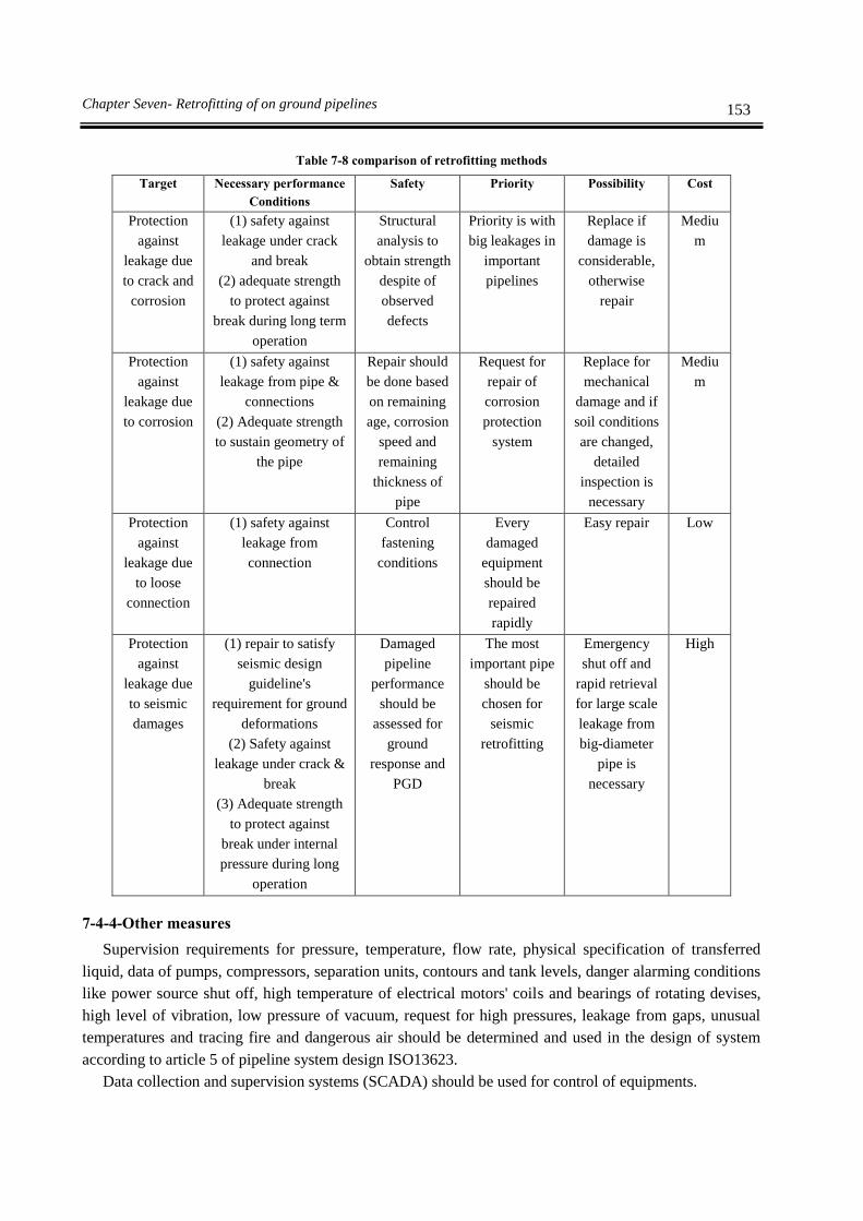
153 Chapter Seven- Retrofitting of on ground pipelines
Table 7-8 comparison of retrofitting methods
Target Necessary performance
Conditions
Safety Priority Possibility Cost
Protection
against
leakage due
to crack and
corrosion
(1) safety against
leakage under crack
and break
(2) adequate strength
to protect against
break during long term
operation
Structural
analysis to
obtain strength
despite of
observed
defects
Priority is with
big leakages in
important
pipelines
Replace if
damage is
considerable,
otherwise
repair
Mediu
m
Protection
against
leakage due
to corrosion
(1) safety against
leakage from pipe &
connections
(2) Adequate strength
to sustain geometry of
the pipe
Repair should
be done based
on remaining
age, corrosion
speed and
remaining
thickness of
pipe
Request for
repair of
corrosion
protection
system
Replace for
mechanical
damage and if
soil conditions
are changed,
detailed
inspection is
necessary
Mediu
m
Protection
against
leakage due
to loose
connection
(1) safety against
leakage from
connection
Control
fastening
conditions
Every
damaged
equipment
should be
repaired
rapidly
Easy repair Low
Protection
against
leakage due
to seismic
damages
(1) repair to satisfy
seismic design
guideline's
requirement for ground
deformations
(2) Safety against
leakage under crack &
break
(3) Adequate strength
to protect against
break under internal
pressure during long
operation
Damaged
pipeline
performance
should be
assessed for
ground
response and
PGD
The most
important pipe
should be
chosen for
seismic
retrofitting
Emergency
shut off and
rapid retrieval
for large scale
leakage from
big-diameter
pipe is
necessary
High
7-4-4-Other measures
Supervision requirements for pressure, temperature, flow rate, physical specification of transferred
liquid, data of pumps, compressors, separation units, contours and tank levels, danger alarming conditions
like power source shut off, high temperature of electrical motors' coils and bearings of rotating devises,
high level of vibration, low pressure of vacuum, request for high pressures, leakage from gaps, unusual
temperatures and tracing fire and dangerous air should be determined and used in the design of system
according to article 5 of pipeline system design ISO13623.
Data collection and supervision systems (SCADA) should be used for control of equipments.

154 Guideline for seismic evaluation and rehabilitation of Gas supply systems
Operation requirements from pipeline system like safety and environmental requirements should be
used as a base to determine the needs of supervising and communication body.
1- Earthquake risk
Different types of remote controlled sensors could be used for lifelines especially to supervise
seismic activities.
2- Review of leakage from pipelines
During operation, all parts of pipe should be checked routinely to be sure they don't leak.
Personnel at site, people near the system and operational officers, find many leakages.
Operational officers should pay especial attention to leakage reports and visual inspections. In
addition, methods other than visual check should be considered as well.
In different steps of leakage detection, possibility and leakage results should be taken into
account. Some of factors which operator should consider for type and period of inspections as
low risk items are as follows:
2-1-Functionality: clean liquid, non corrosion and with low vapor pressure
2-2-Location: far from population, in an operator controlled place, far from non repairable
places, far from rivers with commercial and leisure usage.
2-3-Construction: with materials with acceptable functionality below limit state
2-4-Operation type: operation in low stress level
2-5-Leakage history: shows the years with no leakage
Response time in a leakage or an emergency accident is another important factor which should
be taken into account. Also inspection precision and avoiding faulty recognitions are among
factors which could tolerate the reliability of selected inspection method.
Operators should choose the leakage method very carefully. Scheduled and routine
inspections either aerial, land or marine ones, trapped pressure analysis, monitoring flow and
pressure variation with reference to stable regime, volumetric balance or any other method
which could detect leakage in time are among methods which could be used in systematic
inspection. Inspection periods vary from continuous inspection by computers into daily and
weekly visual inspections. If computerized supervision is going to be used, then the API RP
1130 standard should be used.
Whatever method is chosen, operational officers should inspect and analyze leakage behavior
periodically and give necessary adjustments to decrease the leakage in the selected method.
3- Setup of redundant system as a network system
3-1-Functional concerns in design phase
When there is no need for especial design, design decisions should be based on requested
functions. Three important characteristics of a system which could enhance the emergency
functionality considerably are redundancy, use of standard elements and accessibility to major
elements.
Redundancy is one of the main elements of a system for recovery from limited damages. For a
big distribution system, usually the severe damage centers are recognizable and service to rest
of customers could be continued. But as products passes through one pipe, in case of
transmission systems it could not be acted as distribution systems. In other words redundancy
of these systems is less than redundancy of distribution systems. Although in both systems it
is possible to use redundancy like a pump or compressor to avoid service shut down in an

155 Chapter Seven- Retrofitting of on ground pipelines
emergency situation. Redundant elements are installed for backup purposes and also use them
after damage in main system for repair or replacement of damaged parts.
In addition to considering redundancy in design, it is important to consider the shut down of
system after earthquake, flood or landslide.
3-2-Emergency response system
The most risk is pointed toward those systems which are not designed for earthquake. These
systems should be studied for different types of seismic damages by creating similar case and
emergency response system should be installed if they become necessary.
Chapter 8
Retrofitting of buried pipeline


159 Chapter Eight - Retrofitting of buried pipeline
8-1-Damage modes in earthquake
Different risks and damages are as follows:
1-Seismic risk including landslide, liquefaction and fault movement
2-Structural damages
3-Valve damage
1-Seismic risk including landslide, liquefaction and fault movement
Usually earthquake causes large scale and permanent ground displacements like landslide,
liquefaction and fault movement. Examples of damages due to these displacements are shown
in figures 8-1 and 8-2.
Figure 8-1 large scale ground movement due to landslide
Figure 8-2 deformed pipe in landslide
2-Structural damages

160 Guideline for seismic evaluation and rehabilitation of Gas supply systems
Maximum considered earthquake (MCE) could produce huge tension strains in buried pipeline
due to ground movement. If there is damage potential in weld connection, these strains could
produce crack or damage in the connection.
3- Damage to valves
Buried valves usually are connected with sliding connections to pipe (figure 8-3). Because of
loosening bolts in this connection, it will be vulnerable against ground movement.
Figure 8-3 Sliding connection in buried valve
Therefore the damage modes in pipeline are as follows:
1- Severe damage mode
Severe damage mode for a pipeline is defined as plastic or ultimate limit state with large
displacement and threat to integrity of pipeline.
2- Medium damage mode
Medium damage mode for a pipeline is defined as plastic state with considerable displacement
and threat to pipe integrity for part of the pipe with possibility to operate.
3- Minor damage mode
Minor damage mode for a pipeline is defined as local damage and limited displacement and no
threat to integrity of pipeline.
Structural damage mode for each structural element is given in table 8-1 and functional
damage modes for relevant elements are given in table 8-2.
Table 8-1 Damage modes from structural damage point of view
Structure Elements Structural damage modes
Severe Medium Minor
Structure
Buried pipeline Little damage Little damages Tear
Valve
Small
displacement Relative deformation Break
Inspection elements like manholes
and gates
Equipment for protection against
corrosion

161 Chapter Eight - Retrofitting of buried pipeline
Pipe connected to structural facilities
Pipeline
system
Transmission pipeline Little damage Damages in specific
distances Tear
Control center Little damage Relative damage Collapse
Terminal facilities
Table 8-2 Damage modes from performance point of view
Structure Elements Structural damage modes
Severe Medium Minor
Structure
Buried pipeline Considerable
leakage Relative leakage Little leakage
Valve
defected Usable but should controlled
for adequacy Almost intact
Inspection elements
Equipment for protection
against corrosion
Pipe connected to structural
equipment
Considerable
leakage Relative leakage Low leakage
Pipeline
system
Transmission pipeline Stop working Transmission with low
pressure
Operable with
caution
Control center defected Problem in part of system
Operable with
caution Terminal facilities
Applicable seismic load including wave effects and permanent earth deformation must be
categorized in order to hazard evaluation of pipeline system in this mode.
8-2-seismic assessment procedure
Seismic retrofitting and assessment steps for pipeline system are explained as follows and its
flowcharts is given in figure 8-4 and 8-5
First step: Initial assessment
Second step: Detailed assessment
Third step: seismic retrofitting plan
Forth step: Study adequacy of seismic retrofitting plan
In figure 8-4, several retrofitting criteria are given base on inspection result. In figure 8-5, detail of
inspection process and discuss about the necessity of first and second investigation and seismic
evaluation is given.
1-Initial assessment
Rapid and general study of seismic performance of pipeline system should be done by local
walking inspection. This inspection is necessary to show the need for study and detailed
assessment. Individual or group inspection depends on the importance of pipeline system and
should be controlled and selected prior to inspection.
2-Detailed assessment
Target pipeline and expected seismic performance should be determined on the first step of
assessment and should be approved by the client.

162 Guideline for seismic evaluation and rehabilitation of Gas supply systems
Start
End
No
Does it need retrofitting or renewal?
Initial diagnosis
Diagnosis reportYes
Priority
Replace
Retrofitting or renewal
Cost
Time period
Repair
Replace
Needs
retrofitting
Inspection Inspection
Control
equipment Buried pipeline
Needs renewal?
Yes
No
Risk analysis
(Chain value analysis)
Retrofitting & diagnosis
report
Figure 8-4 Flowcharts for seismic assessment of buried pipeline and control facilities

163 Chapter Eight - Retrofitting of buried pipeline
Start of inspection
End of inspection
Importance of facilities is more?No
Initial diagnosis
Sample
inspection
Initial evaluation
Full inspection
Need for secondary assessment?
Should detailed quality
inspection be done?
YesNo
Detailed
inspection
Standard
inspection
Detection of damage
conditions
Internal
inspection
External
inspection
Assessment with standard
criteria
Allowed stress analysis
Precise strain &
displacement analysis
Does the pipeline have seismic
performance?
Does the pipeline have seismic
performance?
End of inspection
Retrofitting
Simplified non elastic
analysis MCE
MOEAllowed stress analysis
Assessment with standard
criteria
Detection of
damage
conditions
No
YesYes
Yes
External and
internal
inspection
Figure 8-5 Flowcharts for seismic assessment of buried pipeline and its control facilities

164 Guideline for seismic evaluation and rehabilitation of Gas supply systems
8-3-Retrofitting
Retrofitting is done to obtain more effective and economical performance as well as a kind of
damage prevention against earthquake. In the retrofitting of existing pipeline, it should be
done without replacement or omission of buried pipeline as much as possible in order to use
them as long as possible. Burying gas pipelines is a recognized method among execution works
because it costs less comparing to replacement.
8-3-1-Priority in components of retrofitting works
Retrofitting works' priority is done based on following items:
1-To minimize human loss due to earthquake
2-Selecting the pipeline in area with the highest seismic risk
3-To minimize social damages
4-Selection of the most important pipe from risk & financial management point of view
Prioritizing retrofitting of pipe in different leakage conditions could be determined based on table 8-
3.
Table 8-3 Items to be considered for Prioritizing Retrofitting Methods of Buried Pipeline in Different Leakage Conditions
Item Leakage cause
Crack & break Corrosion Loose connection
Buried environment
Beneath road ○ x ○
Natural ground ○ x ○
Inside city ○ x ○
Result of pipeline inspection x ○ x
Leakage history ○ ○ ○
(Note) ○: usable, x: unusable
8-3-2-List of Retrofitting Methods
There are different methods for retrofitting of buried pipeline and some of them are presented
below:
1- Reinforcement of pipeline
Ground's distortion could exert considerable displacements on buried pipe. The common
solution is to determine these places and replace those parts that have displaced. In some
cases in order to release stress the pipeline will be cut. This work will release strains if the pipe
material still is in elastic limit. But if displacement occurs in non elastic region of materials,
residual strains will remain after pipe cut. During the cut big amount of strain energy may be
released which is accumulated in pipeline. Also if the stress level in the pipe is high, sudden
tear off may occur and pipe contents pour out. Relative movement of cut area could change
from few centimeters to few meters. The workers doing this job should be alert of this risk and
take necessary preventive measures to avoid damage due to fire and sudden pipe movement.

165 Chapter Eight - Retrofitting of buried pipeline
Acceptable methods for repair of pipes without buckling, crack and indent are shown in table
8-4. Acceptable methods for repair of pipes without buckling, crack, leakage and indent and
other damages are shown in table 8-5.
Table 8-4 Acceptable Repair Methods (pipes without buckling, cracking and indentation)
Defect
Repair methods
1 2 3 4a 4b 5 6 7 8
Rep
lace
Rem
ovin
g
by
rubb
ing
Sed
imen
tati
on
o
f
wel
d m
etal
Rei
nfo
rcin
g
circ
um
fere
nti
al
cov
er
(typ
e a)
Pre
ssu
rize
d
circ
um
fere
nti
al
cov
er
(typ
e b
)
Co
mpo
site
lay
er
Mec
han
ical
bo
lts
of
clam
p
Val
ve
wit
h
hig
h
tem
per
atu
re
Bra
cket
s
External
corrosion
<0.8 t
Yes1 No Limited
2
Limited5
Yes Limited5 Yes Limited
3 Limited
8
External
corrosion
>0.8 t
Yes1 No No No Yes No Yes Limited
3 Limited
8
Internal
corrosion
<0.8 t
Yes1 No No
Limited5
Yes Limited5 Yes Limited
3 No
Internal
corrosion
>0.8 t
Yes1 No No No Yes No Yes Limited
3 No
Groove or
covering
corrosion of
joint in
EFW &
ERW
welding
Yes1 No No No Yes No Yes Limited
3 No
Gap,
groove or
arc burn
Yes1
Limit
ed7
No Limited5,6
Yes
Limited5
,6
Yes Limited3 Limited
6,8
Crack Yes1
Limit
ed7
No Limited5,6
Yes
Limited5
,6
Yes Limited3 No
Hot point Yes1 No No
Limited5
Yes No Yes Limited3 No
Gas
inclusion
Yes1 No No No Yes No Yes Limited
3 No
fillet
defected
weld
Yes1 No Limited
2 No Yes No Yes No No
Lamellar
tearing Yes
1 No No No Yes No Yes No No
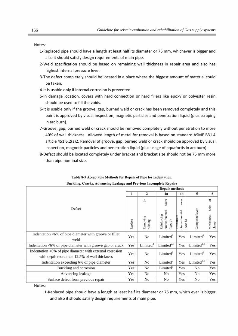
166 Guideline for seismic evaluation and rehabilitation of Gas supply systems
Notes:
1-Replaced pipe should have a length at least half its diameter or 75 mm, whichever is bigger and
also it should satisfy design requirements of main pipe.
2-Weld specification should be based on remaining wall thickness in repair area and also has
highest internal pressure level.
3-The defect completely should be located in a place where the biggest amount of material could
be taken.
4-It is usable only if internal corrosion is prevented.
5-In damage location, covers with hard connection or hard fillers like epoxy or polyester resin
should be used to fill the voids.
6-It is usable only if the groove, gap, burned weld or crack has been removed completely and this
point is approved by visual inspection, magnetic particles and penetration liquid (plus scraping
in arc burn).
7-Groove, gap, burned weld or crack should be removed completely without penetration to more
40% of wall thickness. Allowed length of metal for removal is based on standard ASME B31.4
article 451.6.2(a)2. Removal of groove, gap, burned weld or crack should be approved by visual
inspection, magnetic particles and penetration liquid (plus usage of aquafortis in arc burn).
8-Defect should be located completely under bracket and bracket size should not be 75 mm more
than pipe nominal size.
Table 8-5 Acceptable Methods for Repair of Pipe for Indentation,
Buckling, Cracks, Advancing Leakage and Previous Incomplete Repairs
Defect
Repair methods
1 2 4a 4b 5 6
Rep
lace
Rem
ovin
g
by
rubb
ing
Rei
nfo
rcin
g
circ
um
fere
nti
al
cov
er
(typ
e a)
Pre
ssu
rize
d
circ
um
fere
nti
al
cov
er
(typ
e b
)
Co
mpo
site
lay
er
Mec
han
ical
bo
lts
of
clam
p
Indentation <6% of pipe diameter with groove or fillet
weld Yes
1 No Limited
2 Yes Limited
2 Yes
Indentation <6% of pipe diameter with groove gap or crack Yes1 Limited
4 Limited
2,3 Yes Limited
2,3 Yes
Indentation <6% of pipe diameter with external corrosion
with depth more than 12.5% of wall thickness Yes
1 No Limited
2 Yes Limited
2 Yes
Indentation exceeding 6% of pipe diameter Yes1 No Limited
2 Yes Limited
2,3 Yes
Buckling and corrosion Yes1 No Limited
2 Yes No Yes
Advancing leakage Yes1 No No Yes No Yes
Surface defect from previous repair Yes1 No No Yes No Yes
Notes:
1-Replaced pipe should have a length at least half its diameter or 75 mm, which ever is bigger
and also it should satisfy design requirements of main pipe.

167 Chapter Eight - Retrofitting of buried pipeline
2-In damage location, covers with hard connection or hard fillers like epoxy or polyester resin
should be used to fill the voids or annular space between pipe and repairing cover.
3-It is usable only if the groove, gap, burned weld or crack has been removed completely and
this point is approved by visual inspection, magnetic particles and penetration liquid (plus
usage of aquafortis in arc burn).
4-It is usable only if crack, stress concentration point or other defects has been removed
completely and this point is approved by visual inspection, magnetic particles and
penetration liquid (plus usage of aquafortis in arc burn). Also wall remaining thickness
should not be less than 87.5% of pipe nominal thickness.
2- Anchoring of equipments
Large equipments have to be fixed by anchor rod and frame structures to prevent sliding,
slipping and overturning.
3- Mechanical connections
Movement (rotation and displacements) and loads (forces and moments) should be limited to
values specified by connection manufacturer.
4- Seismic constraints
Seismic force exerted on seismic constraints and its connections into building structures and
anchorage in concrete should be determined by static and dynamics analyses. Seismic strength
of seismic constraints and its connections should be determined based on design standards for
support components like MSS-SP-69, AISC or AISI for steel elements and ACI for concrete
anchors.
5- Anchor movement
In order to prevent vibration or damp them out in pipeline and its equipments, there should be
ample supports and anchors.
Seismic movement of anchor
Seismic anchor movement (SAM) is the movement difference between connecting points of
pipe to support (for example, supports connected to higher stories vibrate with amplitude
larger than the supports connected to lower altitudes) or it is the movement difference
between nozzle connections and pipe supports. Seismic inputs for anchor are displacement
(transfer or rotation) in connections of support or in equipments' nozzle. Stresses and forces
of pipeline system will be combined with stresses and inertial forces (pipe vibration due to
earthquake force) by squared root of sum of squares (SRSS) method.
Branch connection of pipelines on the ground should be protected with consolidated
embankment or sufficient flexibility should be provided.
If openings are used in consolidated embankment for connecting new branches to existent
pipe on the ground, a footing should be provided for main pipeline and new branch to
prevent vertical and lateral movement.
Anchors and dampers will be considered to prevent vibration of pipeline in the main line.
All attachments should be designed to minimize stresses in the pipeline. Welding of
attachments should comply with standard structural execution.

168 Guideline for seismic evaluation and rehabilitation of Gas supply systems
Structural supports, anchors and braces should not weld directly to a pipeline which is
designed to operate in a circular stress 50% or higher. Instead should be reinforced with
elements with complete coverage.
In places where supports like anchor is necessary, attached elements should weld to
covering element. Pipe connection to covering element should be done with continuous fillet
welds instead of consecutive welds.
Supports which are weld to pipeline should be designed in a way to be accessible during
inspection.
Design of anchors
In design of anchor blocks to prevent axial movement of pipeline, forces due to pipeline
expansion and any kind of friction between pipe and soil should be taken into account.
In design of covering element, combination of functional stresses, environment stresses,
construction stresses and random loads should be taken into account. Connection of
covering element attachments could be done using strong brackets or continuous welds.
Axial force, F which the bracket should sustain in the pipeline will be obtained from the
following equation:
hpTTEAF )( 12 8-1
A: Pipe cross section
E: Elastic module
: Linear expansion coefficient
T1: Installation temperature
T2: Metal minimum or maximum temperature during operation
hp: hoop stress due to internal pressure based on wall thickness
ν: Poisson coefficient
Considerable residual forces during the installation also should be taken into account in
calculation of axial forces of pipeline.
Seismic support's requirements
Supports and foundations need to control with a view to seismic requirement.
6- Cathodic protection method
It is possible to protect the pipeline from corrosion completely by design and installing proper
covers and cathodic protection system.
Covers
Cover for intercity pipeline is different from piping in factories. Buried pipeline in factories
are ordered with covers and installed but for intercity pipeline, it is covered at site.
This difference prevents use of some sort of covers for pipeline in factories.
Cathodic protection system
Cathodic protection system is not just flow of electricity in the pipeline. To execute this
method, some requirements like proper covers and conductible cables are necessary.
Cathodic interference
There are two types of cathodic interference, current interference and voltage interference
Current interference:

169 Chapter Eight - Retrofitting of buried pipeline
Figure 8-6 shows a cathodic protection system, rectifier and ground level. Usually this type of
setup will transfer few amperes from soil to protected pipeline.
Voltage interference:
Figure 8-7 simulates the case where voltage interference is produced as high voltage passes
between external pipeline and surrounding soil. High voltage and high density of current
could make soil alkali.
Figure 8-6 Current interference Figure 8-7 Voltage interference
Chapter 9
Retrofitting methods for
internal equipments


173 Chapter Nine - Retrofitting methods for internal equipments
9-1-Target component
Seismic retrofitting of internal equipments is divided into four groups as follows:
1-Air conditioning facilities
2-Building internal piping facilities
3-Building internal cabling and electricity facilities
4-Footing of equipments and support for piping
Details of these four groups are as follows:
1-Air conditioning facilities
1-1-Heating equipments
a) Heating source
b) Cooling source
c) Equipments depending on heating source
d) Equipments depending on cooling source
e) Energy equipments
1-2-Air conditioning
a) Equipments installed on the floor
b) Equipments installed on the ceiling
1-3-Piping for air conditioning
a) Piping
b) Valves
c) Measuring devices
1-4-Duct equipment
a) Duct
b) Dampers
c) Air controlling gates
d) Air controlling canals
1-5-Automatic controlling equipments
a) Automatic control panel
1-6-Exhaust gas fan
a) Exhaust gas fan installed on floor
b) Exhaust gas fan installed on ceiling
1-7-Exhaust gas duct
a) Exhaust gas duct
b) Dampers
c) Exhaust gas gates
d) Exhaust gas canal
2-Building internal piping facilities
2-1-Water system
a) Piping
b) Gauges
c) Tap water valve
d) Water valve
e) Measuring devices
f) Pump

174 Guideline for seismic evaluation and rehabilitation of Gas supply systems
g) Water tank
h) Electricity panel
2-2-Hot water devices
a) Piping
b) Tap water mixing valve
c) Valves & expansion valves
d) Measuring devices
e) Hot water tank & pump
f) Hot water cylinder
g) Electricity panel
2-3-Sewage equipments
a) Piping
b) Pumps
c) Sewage tank
d) Electricity panel
2-4-Sanitary equipments
a) Rest room facilities
b) Hand wash basin
c) Bathroom facilities
d) Kitchen facilities
e) Service facilities
2-5-Gas facilities
a) Gas piping
b) Measuring devices
c) Heat source facilities
d) Other equipments
2-6-Sewage tank equipments
a) Piping
b) Sewage tank
c) Electricity panel
3-Building internal cabling and electricity facilities
3-1-Supply wiring and change
a) Internal electricity wiring
b) Equipments
c) Footing
d) Internal situation
3-2-Private electricity facilities
a) Equipments
b) Footing
c) Internal situation
3-3-Battery facilities
a) Equipments
b) Footing
c) Internal situation

175 Chapter Nine - Retrofitting methods for internal equipments
3-4-Trunk line
a) Metal tube
b) Cable rack
c) Metal duct
d) bus duct
3-5-Electrical Equipments
a) Equipments
b) Internal situation
3-6-Lighting instruments
a) Equipments
3-7-Automatic fire risk alerting alarm equipments
a) equipments
3-8-Lightning rod
a) Lightning rod
4-Footing of equipments and support of piping
4-1-Footing
4-2-Piping
9-2-Seismic damage modes
Seismic damage of equipments is mostly due to aging, loosening of anchoring nuts and defects in
supports. These sections are vulnerable to seismic forces, displacement between different parts of footings
and displacement between ground & building.
Figures 9-1 to 9-8 shows damage modes to equipments in past earthquakes.
9-3-Seismic assessment
Assessment of building equipments should be done based on requested seismic performance after the
earthquake, regardless it is being architectural equipments or piping. Flowchart for seismic assessment of
internal equipments is shown in figure 9-9. In master seismic plans for assessment of important
equipments, following points should be considered:
Necessary measures to secure human safety
Necessary measures to prevent secondary disasters
Maintaining required functionality after earthquake without need for extensive retrofitting works
Regarding other equipments, assessment should be done considering actions necessary to secure the
human lives and preventing secondary disasters. In seismic assessment, required functionality for
equipments in order to secure human lives and preventing secondary disasters, should be determined.

176 Guideline for seismic evaluation and rehabilitation of Gas supply systems
Fig. 9-1 Damage to pipe connection due to
footing independent displacement
Fig. 9-2 Damage to cooling tower. No slide is
reported due to existence of fillers (structures).
Fig. 9-3 Damage to piping of water cooling
system (Due to lateral seismic force, the
welded part of pipe has damaged)
Fig. 9-4 Piping in the building inlet
Fig. 9-5 Damage to sound-proof element
Fig. 9-6 Movement of room unit
Fig. 9-7 Transformer has over turned in open
air electric facilities' site
Fig. 9-8 Damage to transformer and its
elements

177 Chapter Nine - Retrofitting methods for internal equipments
Start
End
Is need for capacity
inspection?
Determine piping &
equipments' functionality
Determine inspection
Is important connecting
equipment?
Ample capacityMain pipe
Important equipment
Inspection of
all items
Inspection
samples
Inspection
Complete Inspection
Inspection
samples
Inspection of
all items
Inspection
Need for renewal or
retrofitting
Renewal or retrofittingDiagnosis report
Renewal Repair
Diagnosis and
retrofitting report
Priority
Cost
Repeat time
EquipmentsPiping
NoNo
YesYes
No
YesYes
No
Yes
No
No
Yes
Figure 9-9 Flowchart for seismic assessment of internal equipments
9-4-Selection of Retrofitting Method as for Safety, Practicability and Cost
In selecting the retrofitting method for facilities, safety, practicability, cost and execution priority
should be considered. Method type could be determined using guidelines mentioned in clause 4-1.
Usually retrofitting methods are determined by considering that during seismic retrofitting of equipments
other parts of building or facilities are serviceable.
Economical concerns in this regard are method's cost and effects of execution conditions.

Chapter 10
Retrofitting methods for other
non-building structures


181 Chapter Ten - Retrofitting methods for other non-building structures
10-1-Target components
In this chapter seismic retrofitting and assessment of usual and vulnerable non-building structures in
gas supply system is presented. These structures namely are culverts for passage of facilities and walls or
dikes around the tanks.
1-Culverts
Culvert's cross section is rectangular and with tow-sided placing mechanism is connected. As it
is shown in figure 10-1 common break mode in culvert in earthquake is shear curvature of cross
section or connection break due to axial displacement or flexural deformation.
Cracks in connection due to flexural
deformation
Cracks due to torsion deformation in
longitudinal direction
Fig 10-1 Usual break modes in culvert
2- Walls and dikes
In this guideline, dike is a structure that will prevent tank liquid leakage during earthquake.
Dike is not considered a fuel facility but is a mean to produce safety during break of fuel
facilities. Therefore, during an earthquake the dike which is designed for seismic performance
of the tank, should stay stable.
dike structure is a reinforced concrete wall or soil depot.
10-2- Culvert
10-2-1- Seismic damages
In an earthquake, seismic damages to culvert are shown in figure 10-2 and are concentrated in the
connections and gaps of the structure.
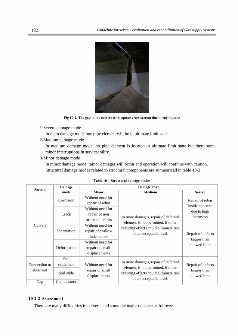
182 Guideline for seismic evaluation and rehabilitation of Gas supply systems
Fig 10-2. The gap in the culvert with square cross section due to earthquake
1-Severe damage mode
In main damage mode one pipe element will be in ultimate limit state.
2-Medium damage mode
In medium damage mode, no pipe element is located in ultimate limit state but there some
minor interruptions in serviceability.
3-Minor damage mode
In minor damage mode, minor damages will occur and operation will continue with caution.
Structural damage modes related to structural components are summarized in table 10-2
Table 10-1 Structural damage modes
Section Damage
mode
Damage level
Minor Medium Severe
Culvert
Corrosion Without need for
repair of rebar
In more damages, repair of defected
element is not permitted, if other
reducing effects could eliminate risk
of an acceptable level.
Repair of rebar
inside concrete
due to high
corrosion Crack
Without need for
repair of non
structural cracks
Indentation
Without need for
repair of shallow
indentation Repair of defects
bigger than
allowed limit Deformation
Without need for
repair of small
displacements
Connection to
abutment
Soil
settlement Without need for
repair of small
displacements
In more damages, repair of defected
element is not permitted, if other
reducing effects could eliminate risk
of an acceptable level.
Repair of defects
bigger than
allowed limit Soil slide
Gap Gap distance
10-2-2-Assessment
There are many difficulties in culverts and some the major ones are as follows:

183 Chapter Ten - Retrofitting methods for other non-building structures
Cracks of solid culverts
Eluviations and loss of structural supports
Water loss of culverts due to corrosion or abrasion
Extra bending and displacement of flexible culverts
Stress cracks in plastic culverts
Increase of culvert gap due the earthquake
Settlement and Increase of gap due to permanent displacement of ground which is caused by fault
displacement or liquefaction

184 Guideline for seismic evaluation and rehabilitation of Gas supply systems
Inspection
Visual assessment
Initial assessment
Detailed assessment
Start
Does it need retrofitting or
renewal?
Assessment report
Retrofitting or renewal
Repair Renewal
Priority
Cost
Time
Retrofitting & assessment reportEnd
Yes
No
Need for retrofitting
Figure 10-3 Flowchart for seismic assessment and retrofitting of culvert
10-2-3-Retrofitting
10-2-3-1-Notes
In design of culverts it is recommended to consider requirements for maintenance period. Although
structural conditions are one of important functions of culverts, but problems related to durability, is the
most cause of damages. Usually culverts age rather than face a structural break. Durability is under two
mechanisms: corrosion and abrasion.
10-2-3-2-Determining retrofitting method from safety, practicability and cost point of view
1-Safety
Safety of personnel should be considered during construction, maintenance, repair and renewal
of culverts. Designer should recognize the least possibility of repeat of risk in the construction
of special type of structures as much as he can.
Repair, maintenance and inspection personnel should be aware of bad weather conditions,
chemical and poisonous containment, animals and collapse potential of unstable structures.
2- Practicability
Culverts are built with reinforce concrete, wave-shape plates and recently with filled walls,
profile walls and reinforced plastic. Strength and physical specification of material depends on
chemical specification and interaction of included material. Metals and plastic are homogeneous
and isotropic material where concrete and masonry materials are mix or combination of
materials.

185 Chapter Ten - Retrofitting methods for other non-building structures
The way materials are interconnected to each other considerably affects material's strength in
structural operation.
3- Cost
For design of new culverts and major repair of culvert, economical analysis usually considers
factors like, construction cost, estimated service life, maintenance cost, replacement cost, fail
risk and financial risk. Long and short term costs should be considered in main design and
repairs or replacements.
10-2-3-3-Selection of retrofitting methods considering culvert material
1-Concrete
Culvert may be built with pre-cast concrete or cast-in-place concrete. Pre-cast sections are
uniform in shape and dimension and are built in sections to be easy for transportation and
installation. It is possible that pre-cast concrete culvert is built with high-strengthened concrete,
but in cast-in-place concrete culvert, special rebar arrangement is used in critical positions in
order to sustain high forces and stresses.
2- Wave-shaped steel
Steel plates and pipes of this type of culverts are built in the factory. But big wave-shaped
culverts are installed at site.
3- Culvert material cover
Different types of covers are used alone or in combination of different layers, to protect culverts
against corrosion or chemical materials. Covers vary on types depending on type of culvert
material, type of aging and or possibility of their occurrence.
4-Cover of metal culverts
Wave-shaped steel culverts are protected with a layer of tin (galvanized) or aluminum
protection covers for metal culverts include tar covers, tar flooring, tar-fibered covers, polymer,
concrete flooring and concrete covers. Protective covers together with metallic covers are used a
lot if there is corrosion or abrasion.
5- Cover for concrete culverts
Concrete culverts are seldom covered during construction. But if they are installed in places
with chemical attack, they will be covered with epoxy resins or special concrete with high
density and low porosity. These concretes have high strength against chemical and chemical
effects.
Most of culverts will last until their useful life. In many cases culverts are built under heavy
slopes and under roads with heavy traffics. Replacement of these culverts has very high cost and
also will cut off traffic.
10-2-3-4-Works other than Retrofitting
In dikes and walls, usually settlement occurs due to earthquake. Monitoring system to diagnose
damage place will be very helpful for assessment and retrofitting of these structures.

186 Guideline for seismic evaluation and rehabilitation of Gas supply systems
10-3-Wall and Dike
10-3-1-Seismic assessment and retrofitting procedure
Retrofitting plan is defined with following flowchart.
Start
Data collection
Data
Initial assessment
(Local inspection)
Secondary assessment
(Detailed inspection)
Laboratory test
calculation
Present wall or dike
Fuel facilities inside dike
Usual seismic provision
Judging on present wall
or dike
Is retrofitting
necessary?
repairrenewal or
Cost
Time
Assessment and retrofitting report Assessment report
Figure 10-4 Flowchart for seismic assessment of dike
10-3-2-Retrofitting method
First priority for inspection should be sections like, connection, opening in pipe, provided gap, water
discharging devise, main body and gate of the dike. Second priority is related to attach parts to main body
of dike like stairs or firefighting chemical foam or ready gravel bag in dike.
First priority is also for ground to prevent ground break like liquefaction.
Regarding retrofitting of main body of dike, selection of the best method like tank or culvert footing
from safety, practicability and cost point of view, should be done as mentioned in previous chapter.
Regarding connection or pipe hole, selection of practical methods is limited and usually is repaired as the
initial condition. If newly installed elements or devises are accessible, this method is usable after
considering safety, applicability and cost.
Regarding wall gap, plastic and stainless flexible material is used instead of old connections with
waterproof plate. Figure 10-5 shows example of gap cross section where flexible material is added. Figure
10-6 shows the real gap installed in concrete wall.

187 Chapter Ten - Retrofitting methods for other non-building structures
Figure 10-5 Gap cross section where flexible material is added to it
Figure 10-6 Gap with flexible material
Water-proof plate Slide rebar
Flexible material

Appendix


Appendix 191
Appendix 1-Classification of subscribers of power transmission network
In this guideline, types of intended subscribers involve home utilization, public utilizations,
agricultural utilizations, industrial utilization, commercial utilizations, lighting and special subscribers. In
following, above-mentioned subscribers are described summarily.
Power branching for home utilizations is applied for a branch that merely established for operation of
ordinary home apparatus and equipments in residential units.
Power branching for public utilization is applied to a branch that is used for public services. Types of
public subscribers can be classified as following.
ministries and their subsidiary offices, the Legislative, the Judiciary, Foundation of Martyrs
and Veterans Affair,Foundation of the Oppressed and Disabled, Foundation of the 15 Khordad,
municipalities and all governmental firms and organizations that aren’t administered as
company (such as Organization of Hajj, Endowment and Benevolent Affairs, Organization of
Management and Planning, Environment Protection Organization, Agricultural-Jihad
organizations of provinces, customs, Port & Maritime Administration, I.R. Iran Civil Aviation
Organization), Joint consumptions of non-residential building complexes, mausoleums,
cemeteries and ghasalkhanehs.
all qualified research institutions and research centers with valid licenses from formal
authorities, Sale positions of petroleum products, Governmental sanitary and remedial centers
such as hospitals, clinics, Centers of medical recognition, Medical centers, all beneficence
institutions and centers, of Red Crescent and Imam Khomeini Relief Committee, residential
complexes and towns, gardens, green areas of cities and consumptions related to beautification
of cities.
cultural centers (such as libraries, museums, registered historical sites), Broadcasting, cinemas,
education and upbringing centers (such as kindergartens, preschools, schools, universities,
educational hospitals, Career and Technical Education centers, schools, seminaries) student
dormitories, student camps, Islamic Development Organization, mosques, Hoseiniehes, tombs
of martyrs, shrine monuments and holy places of recognized religious minorities, sport centers,
Disabled welfare and patronization centers, peoples with disabilities and elders, baths and
clubs.
military and police garrisons and centers
rural and urban drinking water pumpage and refineries, sewage collection refineries and
networks, drainage wells related to water and sewage centers, jungle parks and non-traditional
bakeries
small sanitary and medical centers such as medic recognition, medication centers, medical
centers and physician clinics
traditional bakeries
Agricultural power branching is applied for branching that uses power for pumpage of surfacial and
underground waters or further pumpage of water for production of crops and also have operation licenses
from Regional Water corps. Agricultural subscribers can be divided in two groups including water
pumpage for irrigation (agriculture, further pumpage, pressurized and gravity irrigation) and water
pumpage for production of crops (gardening, animal husbandry, reproduction and culture of aquatic in
internal waters).
192 Guideline for seismic evaluation and rehabilitation of Gas supply systems
Industrial power branching is applied for branching that is used for operation of big industries and
plants (such as production of mushroom, fishery, culture of caterpillar, reproduction and culture of
aquatic in internal waters, poultries and animal husbandries) and small industries and production guilds.
Commercial power branching is applied for branching that is used generally for market places in non-
production centers and also all supply centers. According to International Standard Industrial
Classification of All Economic Activities (ISIC), various types of commercial subscribers can be
presented as following:
Wholesales such as wholesale of all products such as foods, home appliances, office supplies,
etc.
retails such as retailing of all products such as groceries, carnages, supermarkets, bookstores,
boutiques, drugstores and cosmetics stores

Appendix 193
Table 1-Classification of special subscribers
definition of activity Inclusive organizations Subscriber Type
planning and dispatching of received forces and
supplies from various sources, procurement and
collection of reliefs, suitable maintenance and
distribution of facilities to relief forces and
people, planning and coordination for supplying
facilities to inhabit people and for damaged
regions on the basis of precedence, supplying
required communications for relief
organizations and institutions, supplying
required communications for damaged people
province general governors
governments
municipalities
crisis management organizations
unexpected accidents and disaster
staff
Presidency of The Islamic
Republic of Iran
communication and information
systems
staff 1
supplying power to damaged regions to endure
relief operation day and night and prevent
horror of damaged people from darkness,
detection of damaged electrical facilities,
technical inspection of all supply lines,
equipment and connections related to
subscribers in damaged regions and try to
reestablish power transmission system
Regional Electric Companies
power transmission companies
power support 2
Organizations and administrations
of information and security
General Command of Armed
Forces of the Islamic Republic of
Iran
military and police centers
centers of aerial and armed forces
political and
military
3
specialized search to find individuals, required
actions to bring out damaged peoples,
performing basic critical actions in incident
places, remedial actions, supplying sanitary
forces in provisional places and sanitary
controlling of damaged areas, halting and
quenching fire, supplying required safety for
relievers, recognition and debris removing of
relieve paths, supply and distribution of
transportation machines to relief and remove
debris
hospitals, emergency centers and
clinics, Red Crescent populations,
organizations of firefighting and
safety services of cities, Road &
Transportation offices, Relief
committees
auxiliary 4
performing basic critical actions with
coordination of emergency teams, compulsive
housing and providing necessities and primary
utensils of damaged people, supply and
distribute fuel and oil products, water for
drinking and other consumption and also food
The National Iranian Oil Products
Refining &
Distribution
gas companies
water and sewage organizations
Fruits, Vegetable and Agricultural
Products Wholesale Markets
Organizations
critical services 5