guideline for the dismantling and removal of petroleum storage
TRANSCRIPT

GUIDELINE FOR THE DISMANTLING AND REMOVAL OF PETROLEUM STORAGE TANK SYSTEMS
FEBRUARY, 2007
This document outlines the procedures to be followed for the dismantling and removal underground and aboveground storage tank systems and for the initial screening of the site for the presence of contamination.

2
Table of Contents
1. Enabling Legislation ....................................................................................................3
2. Licensed Petroleum Technicians.................................................................................3
3. Application for Permit ..................................................................................................3
4. Tank Removal Safety Precautions ..............................................................................3
5. Underground Petroleum Storage Tanks I. Preparation..................................................................................................3
II. Tank Purging ...............................................................................................4 III. Making the Tank Inert..................................................................................4 IV. Tank Removal .............................................................................................4 V. Tank Disposal..............................................................................................5
VI. Waste Disposal ...........................................................................................5 VII. Soil Testing and Sample Collection.............................................................5
VIII. Project Completion ......................................................................................8
6. Aboveground Petroleum Storage Tanks .....................................................................8
7. Frequently asked Questions........................................................................................9
8. Regional Office Contact Information..........................................................................11
9. Appendix A • Application for Permit to Remove..............................................................12
10. Appendix B
• Underground and Aboveground Petroleum Tank Removal Report...........16
11. Appendix C • Guideline 2002 –02E
Criteria for Acceptance of Contaminated Soil at Licensed Waste Disposal Grounds ................................................................21
12. Appendix D
• Field Soil Screening Method .....................................................................23
13. Appendix E • Analytical Methods ....................................................................................24
14. Appendix F
i. Example Site Diagram...............................................................................26 ii. Example Excavation Diagram ...................................................................27 iii. Example Hydrocarbon Vapour Testing Table ...........................................28 iv. Example Soil Testing Table.......................................................................29

3
1. ENABLING LEGISLATION Manitoba Conservation is responsible for the administration, inspection and enforcement of provincial legislation respecting petroleum storage tank systems. This is accomplished through the Storage and Handling of Petroleum Products and Allied Products Regulation, MR 188/2001, pursuant to The Dangerous Goods Handling and Transportation Act, CCSM D12. This document outlines the general procedures to be used for the dismantling, removal and disposal of underground and aboveground storage tank systems and for the initial screening of the tank site for the presence of contamination. 2. LICENSED PETROLEUM TECHNICIANS The dismantling and removal of a petroleum storage tank system must be done by a Licensed Petroleum Technician. To obtain the list of Licensed Petroleum Technicians that have demonstrated their qualifications and abilities to remove petroleum storage tank systems, contact your regional Environment Officer. 3. APPLICATION FOR PERMIT Prior to removing a petroleum storage tank system the Licensed Petroleum Technician must fill out the “Application for Permit” to remove form. This form must be completed and sent to the regional Conservation office at least fifteen (15) days prior to the removal of petroleum storage tanks. A copy of the permit application can be found in Appendix A. You must receive written approval from the regional Environment Officer before work is to begin. 4. TANK REMOVAL SAFETY PRECAUTIONS When underground and aboveground petroleum storage tank systems are removed, regardless of the reason for removal, precautions must be taken to ensure that the tank and piping are processed and disposed of properly and that any site contamination is identified. Failure to follow proper procedures may result in injury to workers or further contamination. 5. UNDERGROUND PETROLEUM STORAGE TANKS
I. PREPARATION
a. All underground utilities within the designated work area must be located and identified. b. All electric power connected to the tank or its associated equipment must be
deactivated by dismantling the wire at the circuit breaker. c. Barricades must be placed around all excavations, excavated soils, removed tanks, and
equipment until completion of work. d. Any waste products, including sludge, must be removed from the site by a Licensed
Hazardous Waste Carrier and disposed of at a facility approved by Manitoba Conservation.
e. Removal of tank and ancillary equipment must be performed in accordance with industry standards. This includes, but is not limited to, compliance with workplace safety and health legislation, building codes, municipal permits, among others.

II. TANK PURGING
Tank purging means to free the tank of flammable vapours. Methods of tank purging should be carried out according to industry standards, which may include displacement with water or air extraction/mover and diffused air blower. During the purging process, all necessary precautions to prevent ignition in the entire area must be taken. A fuel vapour meter must be used to verify the tank is free of flammable vapours. Tank removal and/or tank destruction may only begin when the reading on the combustible gas meter is less than 10% LEL at any depth within the tank or the atmosphere inside the tank reads 5% or less on an oxygen meter.
III. MAKING THE TANK INERT
Making the tank inert differs from purging in that when you inert a tank, you do not remove the flammable vapours, but rather displace the oxygen in the tank with non-flammable gas. The concentration of oxygen in the tank can be reduced to a level insufficient to support combustion by replacing the oxygen with an inert gas. Making the tank inert must be carried out in accordance with industry standards. Gases commonly used include carbon dioxide (in the form of dry ice) or compressed nitrogen.
CAUTION!
Prior to selecting the displacement method, make sure that arrangements have been made to dispose of the contaminated water by a Licensed Commercial Hazardous Waste Carrier or at a site approved by Manitoba Conservation. On very hot days flammable vapours may reappear in less than one hour. Continuous monitoring is a must. REMINDER: Tank removal and/or tank destruction may only begin when the reading on the combustible gas meter is less than 10% LEL at any depth within the tank or the atmosphere inside the tank reads 5% or less on an oxygen meter. A fuel vapour meter must be used on-site for tank removals. These meters can only be used by persons familiar with their operation, including calibration of the meter as per manufacturer’s requirements.
IV. TANK REMOVAL
a. After the tank has been purged and made inert, the tank and associated piping must be
removed from the excavation. b. The tank shall be examined for any evidence of perforations caused by corrosion or
structural failure. The Licensed Petroleum Technician shall complete the Underground Petroleum Tank Removal Report, confirming the results of the tank examination. (See Appendix B). Copies of this report shall be sent to the owner and Manitoba Conservation.
4

5
c. The tank must be made to provide ventilation and to render it unfit for use. An exception is when the tank will be recertified for re-installation at another location for petroleum storage, or if it is to be used for other storage purposes.
V. TANK DISPOSAL
a. Tanks which are to be re-used for petroleum storage or allied petroleum product must
be refurbished or recertified in accordance with ULC standards. b. Steel tanks may be sent to a scrap dealer so the tanks can be processed and recycled
for their metal content. Fiberglas Reinforced Plastic (FRP) tanks may be crushed by heavy equipment at the site and disposed at the local waste disposal ground.
c. If the tank(s) are to be reused for other than petroleum or allied products, their proposed
use must be detailed in the removal report.
VI. WASTE DISPOSAL
The handling, transport and disposal of wastes associated with the tank removal must be performed in accordance with all relevant regulations and guidelines issued by Manitoba Conservation. Liquid petroleum products and sludge are regulated hazardous waste and must be handled in compliance with the requirements of The Dangerous Goods Handling and Transportation Act. In some cases Manitoba Conservation may require that water from the excavation be tested to determine suitable disposal options. Petroleum impacted soil must be managed appropriately. In most cases treatment of soil is managed as specified in Manitoba Conservation Guideline 96-05 entitled “Treatment and Disposal of Petroleum Contaminated Soil. In some cases the soil may be shipped directly to a licensed waste disposal ground in accordance with Guideline 2002-02E entitled “Criteria For Acceptance of Contaminated Soil At Licensed Waste Disposal Grounds” (refer to Appendix C). Prior to disposal you must submit a Remedial Action Plan (Information Bulletin 96-02E) to Manitoba Conservation. Prior to excavation you must discuss the impacted soil management with your regional Environment Officer. In the advent that temporary on-site storage of soil must be utilized, the regional Environment Officer must be notified in advance for approval.
VII. SOIL TESTING AND SAMPLE COLLECTION
A land owner/storage tank system owner will have one of two possible objectives when a storage tank removal is being contemplated or must be completed:
1. Do I also want the site remediated? 2. Do I just want the tanks removed?
If site remediation is the goal and the removal of petroleum hydrocarbon impacted soil is to be undertaken during the removal of underground storage tanks, a Remedial Action Plan (RAP) must be submitted to Manitoba Conservation prior to any work on the site being initiated. The RAP must adhere to the requirements of Bulletin 96-02E - Submission of Remedial Action Plans (revised January 2004). The RAP is based on pre existing

knowledge of the type and level of contamination at the site usually in the form of a previous site investigation. If storage tank system removal is the only objective and no soil removal is proposed at the time of the underground storage tank removal, hydrocarbon vapour samples of any excavated soils and undisturbed soils at the perimeter of the excavation limits, the pump island(s) and the piping runs must be taken. This is required regardless of whether or not new tanks are to be installed on the site. Hydrocarbon vapour samples must be obtained from each excavation wall and the bottom of the underground storage tank nest using a representative grid pattern. Also, representative hydrocarbon vapour samples must also be obtained every 2 metres along the pipe runs and from underneath the pump island area. Soil samples are to be screened onsite using the field test method described in Appendix D. A minimum of two soil samples from the excavation must be submitted for laboratory analyses and one from the pipe run(s). Parameters to be analysed and the Analytical Methods are listed in Appendix E. These samples ought to be taken from areas with the highest hydrocarbon vapour concentrations and/or areas which are visibly stained. Obviously different analyses must be considered if the contents of the underground tanks are different from those listed in Appendix E (e.g., Allied petroleum products such as uninhibited ethylene glycol, isopropanol, methanol, et.al.). Note: Prior to the work being done, remember to contact the laboratory to obtain the appropriate sample containers, handling and storage instructions.
1) Hydrocarbon Vapour Testing Bottom Samples Obtain a minimum of two representative samples per tank from the bottom of the excavation or in a representative grid. Side and End Wall Samples Obtain representative samples from a grid that allows at least 3 vertical samples (near surface, middle and near bottom of excavation wall) and approximately every two meters horizontally along each excavation wall. Pipe Runs and Pump Islands Obtain representative samples from beneath or adjacent to the pump island and every 2 metres along pipe runs. Excavated Backfill Where it is planned that the excavated backfill is to be returned to the excavation, representative samples must be obtained from the stockpiled material. The Field Soil Screening Method in APPENDIX D can be utilized to
6

pre-screen the material before a sample is obtained for laboratory analysis. This will help to ensure that representative samples are obtained and it will provide insight as to whether or not the material will be able to be returned into the excavation. A composite sample may be used in accordance with Guideline 96-05 Treatment and Disposal of Petroleum Contaminated Soil (revised April 2002).
2) Soil Sample Collection All samples from the excavation should be taken from undisturbed soil after the backfill material has been removed. The samples should be taken approximately 15 cm in from the surface of the excavation wall to avoid sampling soil which has been exposed to the atmosphere. In some situations, additional samples should be taken where layers of porous soil (sand/gravel/silt) are noted in the soil formations exposed in the excavation.
3) Water Well Sampling In some locations, potable water wells are located at a petroleum storage tank system site. These water wells may become impacted with Petroleum Hydrocarbons as a result of system leaks or spills. At these locations Manitoba Conservation requires a water sample be obtained from the water well. Parameters to be analysed and the Analytical Methods are listed in Appendix E.
Note: Prior to the work being done, remember to contact the laboratory to obtain the appropriate sample containers, handling and storage instructions.
All sample results must be reported in the Tank Removal Report submitted by the licensed Petroleum Technician. The Report must also include at a minimum the following information:
• A site diagram showing the location of underground storage tank nest, piping runs, pump
islands, on-site buildings or structures and utilities, on-site water wells (if applicable) reference to neighbouring land use and streets and orientation (e.g., a north arrow). An example of a typical site diagram is shown in Appendix F.
• An excavation diagram showing the locations of all soil samples obtained from the tank nest and pipe runs for both hydrocarbon vapour concentrations and laboratory testing. Refer to sample diagram in Appendix F.
• A table illustrating hydrocarbon vapour testing by sample points. Refer to example in Appendix F.
• A table illustrating soil testing results by sample point. Refer to example in Appendix F. • A copy of laboratory soil testing results. • A description of soil vapour concentration and soil collection methodology including type of
testing equipment used, soil handling protocols and chain of custody. • A copy of the water well sample results (if required).
7

8
VIII. PROJECT COMPLETION
A tank removal project will be considered complete when the tank removal report has been submitted and accepted as complete as per the requirements of this Document. Incomplete or unsatisfactory reports will result in the former storage site being flagged on future property search requests during land acquisitions. Also, enforcement action will be taken upon the Petroleum Technician(s) for failure to comply with his/her license terms and the terms of the Removal Permit. Remember, a tank pull report is not a phase II site investigation.
6. ABOVEGROUND PETROLEUM STORAGE TANKS Most of the above mentioned procedures for removal of underground storage tanks are similar for the removal of aboveground storage tanks. If any situation exists for an aboveground tank removal that is the same as for an underground tank removal, then the same procedure must be followed. As an example, for aboveground facilities that have underground piping, all the removal and soil testing requirements for underground tank removals must be satisfied, including the testing at the pump island/dispenser. For any situation involving an aboveground petroleum storage facility removal, soil vapour samples and soil laboratory samples must be completed by means of the underground storage tank system method. The areas for soil vapour sampling at aboveground storage tank facilities are at any:
• fuel transfer area(s) • areas of prior spills • leakage from the storage tank system • spills or leakage from any other petroleum storage handling, storage or
transportation equipment at the storage site • tank footprint
Soil vapour samples must be conducted in a grid pattern at 2 metre intervals, horizontally, extending just beyond the footprint of the affected area(s). At each location for sampling, vapour concentrations must be measured for each soil type and for any observed staining to a maximum depth of 1 metre. Soil samples must be submitted for laboratory analysis for vapour reading(s) indicating the highest hydrocarbon concentrations. At least one soil laboratory sample must be submitted from tank area and from piping/pump area (if applicable). A tank removal project will be considered complete when the tank removal report has been submitted and accepted as complete as per the requirements of this Document. Incomplete or unsatisfactory reports will result in the former storage site being flagged on future property search requests during land acquisitions. Also, enforcement action will be taken upon the Petroleum Technician(s) for failure to comply with his/her license terms and the terms of the Removal Permit. Contact your regional Environment Officer regarding questions related to the removal of aboveground storage tank systems.

7. FREQUENTLY ASKED QUESTIONS
Q1. Why has Manitoba Conservation changed the format and information required for tank removal reports?
A: The new format will give the department better information to make decisions if further
work is required after the tank removal has been completed. Q2. Who is responsible for filling out the tank removal report? A: The Licensed Petroleum Technician who is performing/supervising the tank removal is
responsible for the filling out the tank removal report properly and completely. Q3. What if a third party collects the soil samples? Do I still have to fill out the sampling
portion of the report? A: The third party collecting the samples can fill out that portion of the report, but it must be
filled out properly and submitted by the licensed petroleum technician who performed/supervised the removal. It is the technician’s responsibility to ensure that the report is filled out correctly. You should review the information needed for the report with the third party before and after sampling has been completed and ensure the lab results are incorporated in the report.
Q4. Do the diagrams have to be to scale? I don’t have experience with surveying, drafting or
computer drawing programs. A: The diagrams do not have to be to scale, but they should be proportionally sized. The
drawings should reasonably resemble the sites and excavations. Q5. Do I have to submit both diagrams? Can I combine the site and excavation/sampling
diagram? A: The report must have a separate site diagram. Otherwise, there would be too much
information in the diagram and it would be illegible. The purpose of having separate diagrams is to make them easier to produce and easier to read.
Q6. Why do I have to indicate where all the samples came from? A: Indicating the location of the samples will help locate potential areas of contamination. If
the locations of the samples are not recorded, any future work on the site would likely require a new set of tests.
9

10
Q7. Why do I have to take water samples from wells on site? A: If contamination of the area has occurred, it can travel to the groundwater. Testing wells
on site will give the department a much better idea to the extent of possible contamination.
Q8. To whom do the permit application and the Underground and Aboveground Petroleum
Tank Removal Report have to be submitted by the Licensed Petroleum Technician? A: The application for permit “Removal” must be submitted to the appropriate Manitoba
Conservation Regional Office via mail or electronic facsimile.

8. REGIONAL OFFICE CONTACT INFORMATION Brandon Office 1129 Queens Avenue Brandon MB R7A 1L9 Fax: (204) 726-6567 Phone: (204) 726-6565
Dauphin Office 27-2nd Ave. S.W. Dauphin MB R7N 3E5 Fax: (204) 638-8626 Phone: (204) 622-2123
Gimli Office 75-7thAve. Gimli MB R0C 1B9 Fax: (204) 642-6108 Phone: (204) 642-6095
Lac Du Bonnet Office Box 4000 Lac Du Bonnet MB R0E 1A0 Fax: (204) 345-1440 Phone: (204) 345-1444
Portage la Prairie Office 25 Tupper Street N. Portage la Prairie MB R1N 3K1 Fax: (204) 239-3215 Phone: (204) 239-3608
Selkirk Office Lower Level 446 Main St Selkirk MB R1A 1V7 Fax: (204) 785-5024 Phone: (204) 785-5022
Steinbach Office Box 2019 Steinbach MB R5G 1N6 Fax: (204) 326-2472 Phone: (204) 346-6060
The Pas Office P.O. Box 2550 The Pas MB R9A 1M4 Fax: (204) 623-1773 Phone: (204) 627-8248
Thompson Office P.O. Box 32 Thompson MB R8N 1X4 Fax: (204) 677-6888 Phone: (204) 677-6703
Winkler Office Main Plaza, 555 Main St Winkler MB R6W 1C4 Fax: (204) 325-1758 Phone: (204) 325-1750
Winnipeg Office 123 Main St, Suite 160 Winnipeg MB R3C 1A5 Fax: (204) 948-2338 Phone: (204) 945-7061 Phone: (204) 945-7272
11

APPENDIX A
Storage and Handling of Petroleum Products and Allied Products Regulation
Application for Permit to Remove
A. Petroleum Technician Information LICENSED PETROLEUM TECHNICIAN FOR PROPOSED PROJECT:
LICENCE NUMBER: PROPOSED START DATE:
B. Environmental Consultant
ENVIRONMENTAL CONSULTANT FOR PROPOSED PROJECT: TELEPHONE:
IF NOT HIRING AN ENVIRONMENTAL CONSULTANT, WHO WILL BE TAKING SOIL VAPOUR SAMPLES AND THE PHYSICAL SOIL SAMPLES?
C. Storage Tank System Owner Information LEGAL NAME: (Corporation or Individual's name; if Corporation-must end in 'Inc' or 'Ltd')
MAILING ADDRESS:
CITY/TOWN/VILLAGE:
PROVINCE:
POSTAL CODE:
CONTACT PERSON:
TELEPHONE:
FAX:
D. Operation (Facility) Information OPERATION NAME: (Common name - Name on sign or name in phone book)
MAILING ADDRESS:
CITY/TOWN/VILLAGE:
POSTAL CODE:
CONTACT PERSON:
TELEPHONE:
FAX:
12

D. Legal Land Description (Complete at least 1 of the 4 Sections). 1.
LOT:___________ BLOCK:___________
PLAN:____________
RIVER LOT#:________
MUNICIPALITY:
2. Q/S________
SECTION:________
TWP:_________
RANGE:________
MERIDIAN:_____
RURAL MUNICIPALITY:
3. CIVIC ADDRESS:
City/Town/Village
4. IF IN UNORGANIZED TERRITORY: LONGITUDE: LATTITUDE:
E. Facility Type
RETAIL: BULK/DISTRIBUTION: MISCELLANEOUS STORAGE:
(total capacity)
Gas Bar 0-50,000 litres Heating oil
Card lock >50,000-100,000 litres Allied Product
Aviation >100,000-500,000 litres Mobile
Fleet vehicles only
>500,000-1,000,000 litres Engine oil (new or used)
Marina >1,000,000 litres Other Petroleum Oils(new or used)
F. Site Sensitivity Distance to nearest Municipal/Private well: Distance to nearest surface water body:
______________________________metres _____________________________metres
Distance to nearest subsurface structure: (basements, crawlspaces, utility corridors, water lines, etc.)
Depth from the surface to the groundwater table:
_______________________________metres _______________________________metres
Neighbouring land use: Underground soil conditions: (not backfill)
(1) Agricultural (1) Sand, gravel
(2) Residential/Parkland (2) Clay
(3) Commercial (3) Till [mix of (1) & (2)]
(4) Industrial (4) Bedrock
13

Part 2 - Storage Tank System Information NOTE: IF THE FACILITY HAS MORE THAN FIVE UNDERGROUND AND/OR ABOVEGROUND TANKS, COPY THIS SECTION AND COMPLETE AS NECESSARY.
1. Designated Tank ID. Number(how the owner numbers the tanks, e.g. Tank 1, Tank 2)
2. Nominal Tank Capacity (in litres, 1 gal. = 4.5L)
3. Tank Manufacturer (if known):
4. Serial Number (if known):
5. Year of Installation (if known):
6. Has tank or product lines ever been suspected or identified as leaking?
Y N
Y N
Y N
Y N
Y N
7. Contents (presently or last stored)
(1) Gasoline 1 1 1 1 1
(2) Diesel 2 2 2 2 2
(3) Aviation fuel 3 3 3 3 3
(4) Alcohol blends 4 4 4 4 4
(5) Heating/furnace oil 5 5 5 5 5
(6) Used oil 6 6 6 6 6
(7) Bulk lube oil 7 7 7 7 7
(8) Allied Petroleum Products 8 8 8 8 8
(9) Other (specify):___________________ 9 9 9 9 9
8. Wells
Groundwater monitoring well/(s) [outside of tank bed]/potable water well(s) on site?
Y N
9. Previous Spills and/or Leaks at this location? Y N
If yes, what is the estimated quantity of product lost?
_____
litres
14

15
Part 3 - Certification I certify that the information contained on this form is complete and accurate Signature of Licensed Petroleum Technician Date Return completed application form to:
REGIONAL OFFICES
The Pas Office P.O. Box 2550 The Pas MB R9A 1M4 Fax: (204) 623-1773 Phone: (204) 627-8248
Gimli Office 75-7thAve. Gimli MB R0C 1B9 Fax: (204) 642-6108 Phone: (204) 642-6095
Thompson Office P.O. Box 32 Thompson MB R8N 1X4 Fax: (204) 677-6888 Phone: (204) 677-6703
Brandon Office 1129 Queens Avenue Brandon MB R7A 1L9 Fax: (204) 726-6567 Phone: (204) 726-6565
Dauphin Office 27-2nd Ave. S.W. Dauphin MB R7N 3E5 Fax: (204) 638-8626 Phone: (204) 622-2123
Winkler Office Main Plaza, 555 Main Street Winkler MB R6W 1C4 Fax: (204) 325-1758 Phone: (204) 325-1750
Lac Du Bonnet Office Box 4000 Lac Du Bonnet R0E 1A0 Fax: (204) 345-1440 Phone: (204) 345-1444
Steinbach Office Box 2019 Steinbach MB R5G 1N6 Fax: (204) 326-2472 Phone: (204) 346-6060
Selkirk Office Lower Level 446 Main Street Selkirk MB R1A 1V7 Fax: (204) 785-5024 Phone: (204) 785-5022
Portage la Prairie Office 25 Tupper Street N. Portage la Prairie MB R1N 3K1 Fax: (204) 239-3215 Phone: (204) 239-3608
Winnipeg Office 123 Main Street, Suite 160 Winnipeg MB R3C 1A5 Fax: (204) 948-2338 Phone: (204) 945-7061 Phone: (204) 945-7072
Personal information is collected under the authority of The Dangerous Good Handling and Transportation Act, the Storage and Handling of Petroleum Products and Allied Products Regulation and is used to issue permits and for enforcement purposes. Information collected is protected by the privacy provisions of The Freedom of Information and Protection of Privacy Act. If you have any questions, contact the Access & Privacy Coordinator, Box 85, 200 Saulteaux Crescent, Winnipeg MB R3J 3W3; 1-204-945-4170.
16
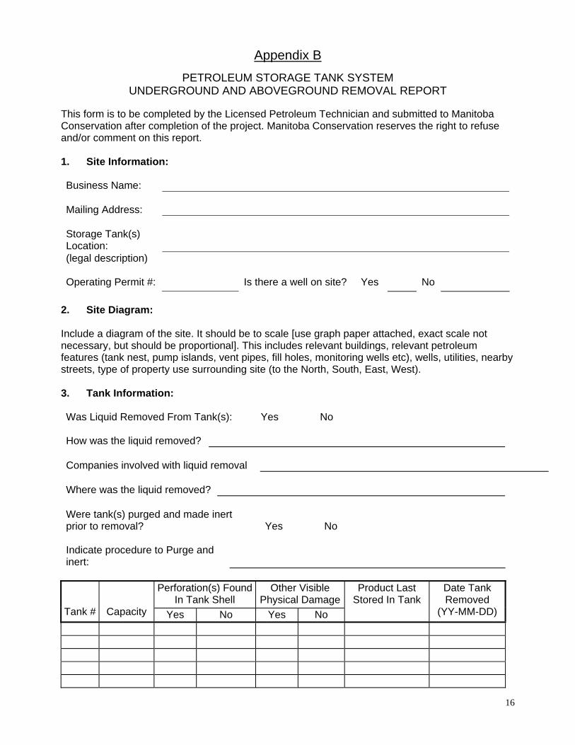
Appendix B
PETROLEUM STORAGE TANK SYSTEM UNDERGROUND AND ABOVEGROUND REMOVAL REPORT
This form is to be completed by the Licensed Petroleum Technician and submitted to Manitoba Conservation after completion of the project. Manitoba Conservation reserves the right to refuse and/or comment on this report. 1. Site Information: Business Name:
Mailing Address:
Storage Tank(s) Location:
(legal description) Operating Permit #:
Is there a well on site?
Yes
No
2. Site Diagram: Include a diagram of the site. It should be to scale [use graph paper attached, exact scale not necessary, but should be proportional]. This includes relevant buildings, relevant petroleum features (tank nest, pump islands, vent pipes, fill holes, monitoring wells etc), wells, utilities, nearby streets, type of property use surrounding site (to the North, South, East, West). 3. Tank Information: Was Liquid Removed From Tank(s): Yes No How was the liquid removed?
Companies involved with liquid removal Where was the liquid removed?
Were tank(s) purged and made inert prior to removal?
Yes
No
Indicate procedure to Purge and inert:
Perforation(s) Found
In Tank Shell Other Visible
Physical Damage
Tank #
Capacity Yes No Yes No
Product Last Stored In Tank
Date Tank Removed
(YY-MM-DD)

17
Was the Product Piping Removed? Yes No Was the Vent Piping Removed? Yes No 4. Testing
A. Was vapour concentration measured in each tank? Yes No B. Were field head space tests done on soils? Yes No If yes, instrument used calibrated on
Number of field tests: Excavation walls Highest reading Excavation base Highest reading Excavated fill Highest reading Pipe trench(es) Highest reading Pump island(s) Highest reading Others Highest reading C. Were soil samples submitted for lab analysis? Yes No Name of Lab Address Number of samples Type of analysis requested D. Were water samples submitted for lab analysis? Yes No Name of Lab Address Number of samples Type of analysis requested
E. Name of Person who performed vapour analysis
Name of Person who performed soil sampling
5. Excavation & Sampling Diagram: Include a diagram of the location of samples taken/recorded in the excavation. It should be to scale (use graph paper, exact scale not necessary, but should be proportional). This includes relevant sampling points and recorded values (location of vapour level tests and results), where samples were taken.

18
6. Disposal:
a. Storage tanks and piping i. Underground storage tanks and piping can not be used again for storage of
petroleum or allied products. ii. Aboveground storage tanks bearing an Underwriter’s Laboratories of Canada (U.L
C.) label may be reused for petroleum products or allied products storage as long as the installation is certified by a Licensed Petroleum Technician.
b. Hazardous waste carrier for liquid disposal:
Disposal date
Disposal location
c. Was any excavated soil removed from site?
Soil volume removed
Disposal/treatment site
7. Petroleum Technician Certification
Licensed Petroleum Technician License Number
Date(s) of tank(s) removal
Date of report completion
I certify that all the above information contained in this report is true and accurate; Signature of Licensed Petroleum Technician

19
SITE DIAGRAM [Provide a Directional Reference (e.g. N )]

20
EXCAVATION & SAMPLING DIAGRAM [Provide a Directional Reference (e.g. N )]

APPENDIX C Guideline 2002-02E May 2002
GUIDELINE: CRITERIA FOR ACCEPTANCE OF CONTAMINATED SOIL AT LICENSED WASTE DISPOSAL GROUNDS
Background: Contaminated soil, typically generated from site remediation projects and environmental accident sites, must be managed in a manner which will ensure that further environmental impacts will not occur. In most cases, treatment of this soil is required, as specified in Manitoba Conservation Guideline 96-05 (April 2002). There may be circumstances, however, in which this soil can be shipped directly to a licensed waste disposal ground, either as waste or as cover material. The purpose of this document is to provide guidance for the management of impacted soil at a waste disposal ground and the application of appropriate acceptance criteria. NOTE: The numeric criteria specified in this document may be varied by a Director of Manitoba Conservation based on the Canadian Council of Ministers of the Environment (CCME) protocols or a prohibition on acceptance can be imposed by the facility operator or by Manitoba Conservation based on site specific concerns. Acceptance Criteria: The acceptance criteria outlined below are based on the latest version of the CCME Canadian Environmental Quality Guidelines for soil and the Canada Wide Standard for Petroleum Hydrocarbons. Any contaminated soil found to contain one or more of the listed parameters at concentration exceeding the criteria shown should not be approved for disposal at a licensed or permitted landfill site1. PARAMETER2 CRITERIA (mg/Kg) Benzene 5.0 Toluene 14 Ethylbenzene 20 Xylene 21 PHC Fraction 1 660 PHC Fraction 2 1500 PHC Fraction 3 2500 PHC Fraction 4 6600
PARAMETER2 CRITERIA (mg/Kg) Arsenic 26 Benzo-a-pyrene 1.4 Ethylene glycol 1800 Pentachlorophenol 28 Phenol 128 Tetrachloroethylene 34 Thallium 3.6 All other parameters under the CCME Canadian Environmental Quality Guidelines shall not exceed the limits provided for the Industrial land use category. Footnotes: Compliance with the criteria for the “BTEX” components may be waived for licensed Class 1 waste disposal grounds equipped with leachate collection systems if analysis of the BTEX components in the leachate is included as a provision of the licence. A description of the derivation of these criteria and explanation of the PHC Fractions is included as Appendix A. Comments:
Any contaminated soil which is not authorized for deposition at a waste disposal ground must be directed to an approved treatment facility as per Guideline 96-05.
Authorization should not be given to dispose of soil at a waste disposal ground that is not in compliance with all regulatory requirements or at a site that is slated for closure due to improper siting or identified environmental concerns, particularly if the potential for groundwater contamination has been identified.
Any request for authorization to dispose of contaminated soil must be accompanied by sufficient lab results to characterize the volume of soil involved. Where applicable, a Remedial Action Plan should also be submitted for departmental review.
21

Contaminants present in the soil must not exceed the provincial leachate criteria. Even if the soil is not classified as hazardous waste, the leachate result should be considered as means of assessing the possible impact on the disposal site. If the results are questionable, deposition at the waste disposal ground should not be authorized.
For waste disposal grounds which operate under a licence containing a numerical limit for total petroleum hydrocarbons in soil (typically 800 ppm), the criteria outlined in this document can be used by the Director to determine when a variance to the licence provisions can be considered.
APPENDIX A The criteria are derived from the CCME 1999 Environmental Quality Guidelines and the proposed 2001 Petroleum Hydrocarbon Canada Wide Standards with the following assumptions: 1. Soils must meet the CCME 1999 Soil
Quality Guidelines and the 2001 Petroleum Hydrocarbon Canada Wide Standard for the Industrial land use category or as specified in this document.
2. The default pathway is the Soil Contact Pathway. Where appropriate, Manitoba
3. Conservation will consider the application of CCME “Off-site migration” values.
4. The soil texture is considered to be Fine Grain. 5. The Surface Depth standard will be applied. 6. Petroleum Hydrocarbon Fractions are
designated by carbon number ranges as follows: Fraction 1 - C6 to C10 Fraction 2 - >C10 to C16 Fraction 3 - >C16 to C32 Fraction 4 - >C32
FOR ADDITIONAL INFORMATION,
PLEASE CONTACT ONE OF THE FOLLOWING REGIONAL OFFICES RED RIVER REGION WESTERN REGION 123 Main Street, Suite 160 1129 Queens Avenue Winnipeg MB R3C 1A5 Brandon MB R7A 1L9 Telephone: (204) 945-7100 Telephone: (204) 726-6064 Facsimile: (204) 948-2338 Facsimile: (204) 726-6567 NORTHWEST REGION EASTERN REGION P.O. Box 2550, Provincial Bldg. P.O. Box 4000 The Pas MB R9A 1M4 Lac du Bonnet MB R0E 1A0 Telephone: (204) 627-8307 Telephone: (204) 345-1486 Facsimile: (204) 623-1773 Facsimile: (204) 345-1440 INTERLAKE REGION NORTHEAST REGION Lower Level, 446 Main Street 59 Elizabeth Drive Selkirk MB R1A 0W6 Thompson MB R8N 1X4 Telephone: (204) 785-5030 Telephone: (204) 677-6703 Facsimile: (204) 785-5024 Facsimile: (204) 677-6652 HEADQUARTERS OPERATIONS 200 Saulteaux Crescent, Box 46 Winnipeg MB R3J 3W3 Telephone: (204) 945-7094 Facsimile: (204) 948-2420 French version available on request, Directives 2002
22

APPENDIX D
FIELD SOIL SCREENING METHOD
The following procedure can be used as an initial indication of the presence of elevated levels of volatiles in soil samples. This method is most applicable to granular soils contaminated with a product such as gasoline that has a relatively high concentration of lighter end, volatile components. Use of the field headspace test should be restricted to sites where contamination by volatile hydrocarbons is being investigated. The method should not be used for determining the presence of middle distillates or heavier products. Also, the effect of methane from soils with a high organic content must be considered. The field screening method is used primarily as a comparative procedure to delineate areas with elevated levels of volatile vapours in the soil. It is not, in itself, a quantitative method that can be used as a final determination of site conditions. The field screening method must be supported by confirmatory lab analyses of representative soil samples. The recommended field screening method is as follows: 1. Soil samples collected from boreholes or excavations are placed in clean sealable plastic bags.
Where possible, samples of heavier consolidated soils should be broken up by hand before being placed in the container. Regardless of the method used, it is important that the soil sample be sealed in the container as quickly as possible to minimize the loss of volatile hydrocarbons.
2. Equipment used to obtain samples (trowels, split spoon samplers, gloves, etc.) must be
properly cleaned after each sample to prevent cross contamination. 3. Sample containers are left in an ambient temperature of approximately 20 degrees Celsius for
a period of 10 minutes. Some sources recommend agitating the sample for 10 to 15 seconds prior to allowing it to stand. This is an optional feature, however all samples from one site must be treated in the same manner.
4. After the 10-minute period, the probe of the vapour analyzer is inserted in the bag. The probe is
inserted to half the depth of the headspace in the container. The highest reading noted in the first 15 seconds after insertion is recorded. The vapour analyzer must be an instrument capable of detecting volatile hydrocarbons on a scale measured in parts per million. This would include instruments employing thermal conductivity, photo ionization or flame ionization detection principles. The use of detector tubes based on a colour change method is not recommended for this purpose. Calibration curves should be available for the instrument, and the instrument should be calibrated during a field investigation.
23

APPENDIX E
ANALYTICAL METHODS
1. SOIL
CONTAMINANT
PARAMETERS
METHOD OF ANALYSIS
Gasoline
BTEX. F1, F2.
[BTEX = Benzene, Toluene, Ethyl benzene, Xylenes; Hydrocarbon Fraction F1 = (nC6-nC10) and F2 = (nC10 to nC16)].
Diesel Fuel (Fuel Oil)
F2, F3.
[Hydrocarbon Fraction F3 = (nC16 to nC34)].
Kerosene
F1, F2, F3. Naphthalene.
Motor Oil, Waste Oil, Bunker C
F2, F3, F4.
[Hydrocarbon Fraction F4 = (nC34 to nC50); Reported as F4 (Gas Chromatograph analysis of extractable hydrocarbons; or as F4G (Gravimetric Heavy Hydrocarbons) whichever is greater].
Aviation Fuel (Jet A)
F1, F2, F3. Naphthalene. Benzo[a]pyrene.
Aviation Fuel (Jet B)
BTEX. Naphthalene. F1, F2, F3.
F1, F2, F3, F4: C.C.M.E¹. "Reference Method for the Canada Wide Standard for Petroleum Hydrocarbons in Soil-Tier 1 Method", ISBN 1-896997-01-5, December, 2000 BTEX: Methanol Extraction GCMS (EPA 5035A High Concentration Method / 8260B) Naphthalene, Benzo[a]pyrene: Methanol Extraction GCMS (EPA 5035A High Concentration Method / 8260B) or Micro-Scale Solvent Extraction GCMS (EPA 3570 / 8270D)
24

2. WATER
CONTAMINANT
PARAMETERS
METHOD OF ANALYSIS
Gasoline
BTEX.
[BTEX = Benzene, Toluene, Ethyl benzene, Xylenes]
TPH. [TPH = Total Petroleum Hydrocarbons
Diesel Fuel (Fuel Oil)
Naphthalene.
[impact to water - aquatic life only].
Benzo[a]pyrene. TPH.
[TPH = Total Petroleum Hydrocarbons
Kerosene
Naphthalene.
[impact to water - aquatic life only].
TPH.
Motor Oil, Waste Oil, Bunker C
TPH.
Aviation Fuel (Jet A)
Naphthalene.
[impact to water - aquatic life only].
Benzo[a]pyrene. TPH.
Aviation Fuel (Jet B)
BTEX. Naphthalene.
[impact to water - aquatic life only].
TPH.
The latest edition of Standard Methods for the Examination of Water and Wastewater; a joint publication of the American Public Health Association (APHA), American Water Works Association (AWWA) & Water Environment Federation (WEF).
25
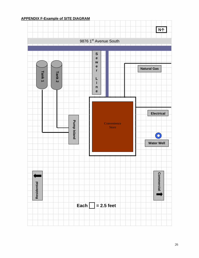
APPENDIX F-Example of SITE DIAGRAM
N
9876 1st Avenue South
Each = 2.5 feet
Tank 2
Tank 1
Convenience Store
l
Pump Island
l
Natural Gas
Res
iden
tial
Sewe r
L i n e
Water Wel
Electrica
Com
mercial
26

Example of EXCAVATION & SAMPLING DIAGRAM
27

28
EXAMPLE HYDROCARBON VAPOUR TESTING TABLE
Location of Vapour Sample
Vapour Reading
Unit of Measurement[L.E.L. or p.p.m.]
Excavation walls Sample 1 Sample 2 Sample 3 Sample 4 Excavation base Sample 1 Sample 2 Sample 3 Sample 4 Excavated fill Sample 1 Sample 2 Sample 3 Sample 4 Pipe trench(es) Sample 1 Sample 2 Sample 3 Sample 4 Pump island(s) Sample 1 Sample 2 Sample 3 Sample 4 Others Sample 1 Sample 2 Sample 3 Sample 4

29
EXAMPLE HYDROCARBON SOIL TESTING TABLE
Location of Soil Sample
Parameters Tested
Lab Results* [ug/g]
Excavation walls Excavation base Excavated fill Pipe trench(es) Pump island(s) Others
*Copy of Laboratory Results MUST be Submitted with Report