guidelines for conceptual design short span bridges
TRANSCRIPT

8/2/2019 Guidelines for Conceptual Design Short Span Bridges
http://slidepdf.com/reader/full/guidelines-for-conceptual-design-short-span-bridges 1/131
Guidelines for conceptual design of short-span bridges
Master of Science Thesis in the Master’s Programme Structural Engineering and Building Performance Design
GEORGI NEDEVUMAIR KHAN
Department of Civil and Environmental Engineering Division of Structural Engineering
CHALMERS UNIVERSITY OF TECHNOLOGYGöteborg, Sweden 2011Master’s Thesis 2011:71

8/2/2019 Guidelines for Conceptual Design Short Span Bridges
http://slidepdf.com/reader/full/guidelines-for-conceptual-design-short-span-bridges 2/131

8/2/2019 Guidelines for Conceptual Design Short Span Bridges
http://slidepdf.com/reader/full/guidelines-for-conceptual-design-short-span-bridges 3/131
CHALMERS, Civil and Environmental Engineering, Master’s Thesis 2011:71
MASTER’S THESIS 2011:71
Guidelines for conceptual design of short-span bridges
Master of Science Thesis in the Master’s Programme Structural Engineering and
Building Performance Design
GEORGI NEDEV
UMAIR KHAN
Department of Civil and Environmental Engineering Division of Structural Engineering
CHALMERS UNIVERSITY OF TECHNOLOGY
Göteborg, Sweden 2011

8/2/2019 Guidelines for Conceptual Design Short Span Bridges
http://slidepdf.com/reader/full/guidelines-for-conceptual-design-short-span-bridges 4/131
CHALMERS, Civil and Environmental Engineering, Master’s Thesis 2011:71
Guidelines for conceptual design of short-span bridges
Master of Science Thesis in the Master’s Programme Structural Engineering and
Building Performance Design
GEORGI NEDEVUMAIR KHAN
© GEORGI NEDEV, UMAIR KHAN, 2011
Examensarbete / Institutionen för bygg- och miljöteknik,Chalmers tekniska högskola 2011:71
Department of Civil and Environmental Engineering
Division of Structural Engineering
Chalmers University of Technology
SE-412 96 Göteborg
Sweden
Telephone: + 46 (0)31-772 1000
Cover:Abstraction of conceptual design process for bridge design, from Georgi Nedev
Department of Civil and Environmental Engineering, Göteborg, Sweden 2011

8/2/2019 Guidelines for Conceptual Design Short Span Bridges
http://slidepdf.com/reader/full/guidelines-for-conceptual-design-short-span-bridges 5/131
CHALMERS, Civil and Environmental Engineering, Master’s Thesis 2011:71 I
Guidelines for conceptual design of short-span bridges
Master of Science Thesis in the Master’s Programme Structural Engineering and Building Performance Design
GEORGI NEDEV
UMAIR KHANDepartment of Civil and Environmental EngineeringDivision of Structural Engineering
Chalmers University of Technology
ABSTRACT
Although conceptual design is known since decades, there is still limited knowledgeon how to apply it, specifically for bridge projects. Most often engineers base theirdecisions on past experience and standard solutions,, which is probably not always themost effective way to approach different problems. Short-span bridges account formost of the solutions for small river crossings, road intersections and so on. Eventhough they rely mostly on beam or slab solutions, still the choice of material, shapeand other properties is not followed by a structured way of thought but rather onprevious experience. Ramböll Gothenburg needed a structured procedure forconceptual design. Therefore the purpose of this project was to develop guidelines and
a step-by-step procedure, which will support a systematic approach for conceptualdesign of short-span bridges. In order to achieve this, the most common demands andsolutions were identified. Consequently, the link between demands and solutions wassearched for, i.e. which solution is appropriate in what situation. The created step-by-step procedure was implemented in Excel toolbox and consists of several modules andis flexible and open for further improvements. This thesis work is based on collectedinformation from literature, continuous interviews with professionals in bridge design,case studies and author’s knowledge. Most of the collected information is from theSwedish practice and the consultancy company Ramböll, which slightly limits thereliability of the guidelines and procedure for international use. Further limitations arethe maximum length of 30 meters and focus only on road and railway bridges. The
developed guidelines were tested on two case studies, which showed a promising toolthat gave reasonable results. The developed approach seems to be good forpreliminary evaluation of appropriate proposals and also acts as supplementary for thedesigner mainly as a documentation tool that presents the concepts to the client in astructured way. Further improvements can be refining the toolbox data, increasing thespan length limitation and implementing pedestrian bridges.
Key words: conceptual bridge design, short-span bridges, guidelines, Excel toolbox,
step-by-step procedure

8/2/2019 Guidelines for Conceptual Design Short Span Bridges
http://slidepdf.com/reader/full/guidelines-for-conceptual-design-short-span-bridges 6/131
II CHALMERS, Civil and Environmental Engineering, Master’s Thesis 2011:71
Contents
ABSTRACT I
CONTENTS II
GLOSSARY V
PREFACE VII
1 INTRODUCTION 1
1.1 Background 1
1.2 Aim, scope and limitations 2
1.3 Approach 3
1.4 Outline of contents 3
2 CONCEPTUAL DESIGN OF BRIDGES 5
2.1 General on conceptual design 5
2.2 ’Five-step’ approach for conceptual design 7
2.3 Overview of demands for bridges 112.3.1 Technical demands 112.3.2 Architectural demands 122.3.3 Production demands 132.3.4 Economical demands 14
2.3.5 Service life demands 152.3.6 Environmental care and sustainability 15
2.4 Current practice in Sweden 162.4.1 Swedish building industry 162.4.2 Conceptual design in consultancies 172.4.3 Common problems faced 19
2.5 Practical lessons learned from the ‘Virserum’ timber bridge 20
2.6 Conditions and constraints affecting bridge design in Bulgaria,Pakistan and worldwide 24
2.7 Summary 26
3 CLASSIFICATION OF THE MOST TYPICAL DESIGN SITUATIONS 27
3.1 Methodology and approach 27
3.2 Classification of demands, constraints and conditions 28
3.3 Refining of design situations and classification 29

8/2/2019 Guidelines for Conceptual Design Short Span Bridges
http://slidepdf.com/reader/full/guidelines-for-conceptual-design-short-span-bridges 7/131
CHALMERS, Civil and Environmental Engineering, Master’s Thesis 2011:71 III
4 DIFFERENT SOLUTIONS FOR SHORT-SPAN BRIDGES 33
4.1 Concrete bridges 334.1.1 Slab-frame cast in-situ 33
4.1.2 Beam-frame cast in-situ 354.1.3 Integral abutments (jointless bridges) 364.1.4 Simply supported slab cast in-situ with end walls 374.1.5 Simply supported beam cast in-situ 384.1.6 Through concrete beam cast in-situ – flat type 384.1.7 Through concrete beam cast in-situ – ribbed type 394.1.8 Prefabricated prestressed hollow core elements 404.1.9 Prefabricated prestressed beam elements 414.1.10 Prefabricated pedestrian and bicycle tunnel 42
4.2 Steel bridges 424.2.1 Corrugated steel tube 43
4.3 Timber bridges 444.3.1 Stress-laminated plate 454.3.2 Beam with timber deck 464.3.3 Beams with LVL deck 464.3.4 Hanging truss 474.3.5 Lower arch 48
4.4 Composite bridges 484.4.1 Steel I-girders and cast in-situ concrete deck 484.4.2 Steel I-girders and prefabricated concrete deck panels 494.4.3 Steel I-girders and FRP deck 504.4.4 Timber girders and cast in-situ concrete deck 524.4.5 ’Folded plate system’ 53
4.5 Summary 54
5 ‘DEMAND-SOLUTION’ GUIDELINES FOR CONCEPTUAL DESIGN 55
5.1 Approach and limitations 55
5.2 General description and aim 565.2.1 Step 1 – Demand case identification 575.2.2 Step 2 - Reducing solution space 67
5.2.3 Step 3 - Demand prioritising 705.2.4 Step 4 - Ranking of possible bridge types 76
5.3 Comparison between Niemeyer’s ‘five-step’ and ‘demand-solution’methodologies 78

8/2/2019 Guidelines for Conceptual Design Short Span Bridges
http://slidepdf.com/reader/full/guidelines-for-conceptual-design-short-span-bridges 8/131
IV CHALMERS, Civil and Environmental Engineering, Master’s Thesis 2011:71
6 CASE STUDIES 81
6.1 The Backaå bridge 816.1.1 Background 81
6.1.2 Input and results 826.1.3 Comparison with the real case 86
6.2 The Bräcke bridge 866.2.1 Background 866.2.2 Input and results 876.2.3 Comparison with the real case 926.2.4 Critical remarks 93
6.3 Conclusions 93
7 CONCLUSION 94
7.1 Concluding remarks 94
7.2 Further development 95
REFERENCES 96
APPENDIX A: DESCRIPTION OF THE TOOLBOX B
APPENDIX B: QUESTIONNAIRES I
APPENDIX C: FEEDBACK FOR THE TOOLBOX L
APPENDIX D: CASE STUDY RESULTS N

8/2/2019 Guidelines for Conceptual Design Short Span Bridges
http://slidepdf.com/reader/full/guidelines-for-conceptual-design-short-span-bridges 9/131
CHALMERS, Civil and Environmental Engineering, Master’s Thesis 2011:71 V
Glossary Angle of skew – the angle between the abutments and the centreline of the bridge (seeFigure 0.1).
Figure 0.1 Skew angle (skewed bridge), (ESDEP)
Bridge length – the distance between the end-supports (abutments) or walls (forframe bridges), see Figure 0.2.
Figure 0.2 Length definition
Conceptual design – the initial and most creative stage of the design process wherethe basic concept is specified. This stage of design involves creation and choice of concepts by evaluation of different solutions for not entirely specified problem.
Conditions – current state of circumstances and local properties - can begeotechnical, spatial, weather, infrastructure and others. They are interconnected withconstraints.
Constraints – restrictions, which affect designer’s choices and possibilities. They canbe space, time, money, and so on.
Cost overrun – an unexpected excess of costs incurred in relation to a budgetedamount due to an under-estimation of the actual costs during budgeting.
Demand – certain qualities and properties of the product (bridge) representing thedesires of the client/society that should be given priority in the design.

8/2/2019 Guidelines for Conceptual Design Short Span Bridges
http://slidepdf.com/reader/full/guidelines-for-conceptual-design-short-span-bridges 10/131
VI CHALMERS, Civil and Environmental Engineering, Master’s Thesis 2011:71
Need – a need is psychological or physical thing for organisms to live. In bridgeengineering, it is basically the necessity to transport goods and people across anobstacle or to improve the existing connection.
n.a. – not available data or information.
Short-span bridges – bridges that have a length between end supports not more than30 m. They can have one or multiple spans.
Situation – particular set of conditions, circumstances and constraints. It is based onevaluation of the current state and possibilities (economical, geographic, climate,social).
Superstructure – the structure above the bearings (road deck and surfacing, load-bearing system).
Substructure – the structure below the bearings (abutments, supports, wings, pilesand etc.).
Requirements – certain needs to be satisfied in a defined way (by authorities, society,technology). They can be fixed or flexible parameters and at the same time theyimprove and increase with evolution of mankind. Requirements are necessary to fulfilin order to ensure value and utility of the final product.
Tectonics – architectural aspects of technology.
Trafikverket – the Swedish Transport Administration. Before 2000, two separateadministrations existed - Vägverket (Road Administration) and Banverket (Rail
Administration).

8/2/2019 Guidelines for Conceptual Design Short Span Bridges
http://slidepdf.com/reader/full/guidelines-for-conceptual-design-short-span-bridges 11/131
CHALMERS, Civil and Environmental Engineering, Master’s Thesis 2011:71 VII
Preface
This project work was carried out during the period January - June 2011 at ChalmersUniversity of Technology in collaboration with Ramböll’s local office in Gothenburg.
This master thesis project was a great opportunity to get deeper knowledge aboutbridges and conceptual design. It was also a chance to see how consultancies work and to learn from them.
We would sincerely like to thank Mattias Hansson, our supervisor from Ramböll, forhis incredible and supporting attitude throughout this thesis work along with thewhole bridge department. On behalf of Ramböll he provided us with all the necessaryresources and support and made us feel like home at our new office. The help fromengineers from the bridge department despite their busy schedules is highlyappreciated.
Likewise, we would like to express our gratitude to Björn Engström who was oursupervisor and examiner at Chalmers. He was always our guide and source of knowledge. His mentorship was keeping us on the right track and giving usmotivation.
Our work would not have been so productive without the practical experience gainedfrom interviews with Christer Carlsson from Ramböll Stockholm and talks withspecialists and professionals in bridge engineering from Trafikverket.
Last but not least, we would like to thank our families for the unstopping supportduring our education and their motivating words.
Göteborg, June 2011
Georgi Nedev and Umair Khan

8/2/2019 Guidelines for Conceptual Design Short Span Bridges
http://slidepdf.com/reader/full/guidelines-for-conceptual-design-short-span-bridges 12/131
VIII CHALMERS, Civil and Environmental Engineering, Master’s Thesis 2011:71

8/2/2019 Guidelines for Conceptual Design Short Span Bridges
http://slidepdf.com/reader/full/guidelines-for-conceptual-design-short-span-bridges 13/131
CHALMERS, Civil and Environmental Engineering, Master’s Thesis 2011:71 1
1 Introduction
The word ‘design’, which is commonly used, plays an important role in our dailylives. Every product that is seen and perceived was born first as an idea in
someone's mind. This idea probably passed through a design process (procedure).Why a product should be designed in the first place? What is the design process?The answer to the first question is very simple – need naturally provokes solutions,i.e. products to be designed. However, according to Dekker (2000) the answer tothe second question is rather complicated, because the design process involves thefollowing four phases:
1) Analysis of the problem (needs)
2) Conceptual design
3) Embodiment design
4) Detailed design
This thesis focuses on the first two points – ‘analysis of the problem’ and‘conceptual design’ of bridges.
1.1 Background
The history of bridges is probably as old as the human civilisation. The idea to buildbridges is inspired by the nature itself – they are part of the environment (see Figure
1.1).
Figure 1.1 Natural bridge (www.nationalgeographic.com)
Bridges are one of the most important and possibly difficult structures in civilengineering. It is no coincidence that they form a special branch of structuralengineering and most consultancies have departments working solely on bridgedesign. In the modern era, bridge engineering has improved tremendously and variousfactors are taken into account while developing the concept of a new bridge. Whensociety puts increasing demands and requirements on bridges it is the engineer’s task and goal to satisfy all of them as much as possible. These factors not only involve the

8/2/2019 Guidelines for Conceptual Design Short Span Bridges
http://slidepdf.com/reader/full/guidelines-for-conceptual-design-short-span-bridges 14/131
2 CHALMERS, Civil and Environmental Engineering, Master’s Thesis 2011:71
safety of the structure but also the economy, constructability, inspectability,durability, sustainability, aesthetics and how to achieve the best fit in the landscapeand environment. That is why a holistic approach is needed to meet all therequirements and their interdependence.
‘..Engineers operate at the interface between science and society’ ~ Dean Gordon Brawn
Even though the conceptual phase of design is known to engineers since a long time,there is still a lapse of specific knowledge on how to approach the problem in a moresystematic way. Just recently a module of a code for conceptual design wasintroduced – fib (2010): Model code 2010. The following steps of the design areguided by certain rules, codes or guidelines – among these the Swedish specificationVägverket (2009) (TK Bro), which take into account the Eurocodes, Vägverket (2004)(BRO 2004, not valid any more but used as a supplementary document), and thepublications of the Swedish Transport Administration (Trafikverket) and so on.
Different authors have tried to look at the problem from different perspectives - Kroll(2001), Lövqvist (1994), Dekker (2000), Niemeyer (2003), fib (2000).
During the 60’s and 70’s a vast amount of the bridges built in Sweden were designedfrom a mainly structural engineers’ perspective, i.e. solutions were based on the mostefficient static scheme and use of material. Architectural aspects during conceptualdesign were missing, which was realised by the society and its representativeauthorities later on. That is one reason why a holistic approach was needed and effortshave been made to implement it. More information can be found in publications of theSwedish Transport Administration: Vägverket (1997) and Vägverket (1999).
The problem Ramboll’s conceptual design engineers in Gothenburg was facing waslack of a structured methodology to work especially during discussions and meetingswith the client. They needed an interactive tool that visualizes and supports theirdecisions and choices and convinces the client why a certain alternative is proposed.Moreover, information and experience were not documented systematically but theinformation was only in the designer’s memory.
1.2 Aim, scope and limitations
The main aim of this research was to develop an approach and guidelines for
conceptual design of short-span bridges. The final outcome of the thesis should be astep-by-step procedure for approaching conceptual design, which will provideengineers with a suggestion for the most suitable solutions for given input parameters.
The objective is to develop a step-by-step design procedure with guidelines including:
A classification of different situations (demands, conditions, constraints)
A compilation of the most common and appropriate solutions (structuralsystems) for short-span bridges, including some new trends and internationalknowledge
A prioritising-of-demands tree identifying the most important aspects for aspecific project

8/2/2019 Guidelines for Conceptual Design Short Span Bridges
http://slidepdf.com/reader/full/guidelines-for-conceptual-design-short-span-bridges 15/131
CHALMERS, Civil and Environmental Engineering, Master’s Thesis 2011:71 3
Ranking (or evaluation) matrixes to compare the alternative solutions
Recommendations for further evaluation of the chosen concept
The scope of the thesis is ’short-span bridges’ with total length up to 30 meters. Even
though, the work is further restricted by the following limitations:
The developed design procedure is generalised and cannot handle well rareand unusual cases (with very special requirements or conditions)
The knowledge acquired from practising engineers is mostly from Ramböll’sconsultants
The big branch of pedestrian bridges is not covered in this thesis work
Even though short-span bridges represent a narrow scope they account for a big part
of the built bridges today.
1.3 Approach
This project used two main sources of information and knowledge acquisition –literature studies and interviews with specialists in the field. First, the literaturestudies were done and after that a series of interviews was carried out. Theinterviewed persons represented two main parties involved in conceptual design –engineers (designers) and clients. Complementary knowledge was also gained byconstant oral discussions with engineers from Ramböll’s office and a short study tripalong E6 highway north of Gothenburg.
All the information found was used to identify the important factors influencing thedesign and the reasoning behind decisions. Categorisation of the most common designsituations in practice was done. Furthermore, the most suitable and bridge types forshort-span bridges were proposed. Afterwards an interactive toolbox was developed tolink these demands cases with promising solutions. Certain make-or-brake issues weresearched for and implemented. A toolbox was created to be flexible and easy tofollow. Moreover, the focus was on the practical use and especially its value whenshown to the client. Finally, these guidelines were developed by an iterative processand continuous re-evaluation. Two short case studies were done to test the toolboxand the methodology as a whole.
1.4 Outline of contents
This thesis consists of seven chapters, a list of references and appendices. It covers anoverview of the existing conceptual design knowledge and proposes a new approachfor conceptual design of bridges with total length up to 30 meters proposing the mostappropriate solutions. Chapters 3, 4, 5 and 7 were written by Georgi Nedev while theremaining chapters by Umair Khan. The Excel toolbox was developed by the twoauthors together.
Chapter 2 gives an overview of conceptual design as a process based on research
work of different authors and how it is approached currently in Swedishconsultancies.

8/2/2019 Guidelines for Conceptual Design Short Span Bridges
http://slidepdf.com/reader/full/guidelines-for-conceptual-design-short-span-bridges 16/131
4 CHALMERS, Civil and Environmental Engineering, Master’s Thesis 2011:71
Chapter 3 classifies and summarises the most common design situations for short-span bridges based on literature studies and interviews with practising engineers.
Chapter 4 lists the most common and appropriate solutions for short-span bridges,though only for road and railway traffic.
Chapter 5 presents the developed step-by-step (‘demand-solution’) approach forconceptual design
Chapter 6 presents a short case-study, concerning the application of the ‘demand-solution’ methodology on a real project.
Chapter 7 gives summary and conclusions and proposes suggestions for furtherresearch on the topic.

8/2/2019 Guidelines for Conceptual Design Short Span Bridges
http://slidepdf.com/reader/full/guidelines-for-conceptual-design-short-span-bridges 17/131
CHALMERS, Civil and Environmental Engineering, Master’s Thesis 2011:71 5
2 Conceptual design of bridges
This chapter gives an introduction to the conceptual design process itself and providesunderstanding on the complexity of the problem.
‘Engineering problems are under-defined; there are many solutions, good, bad andindifferent. The art is to arrive at a good solution. This is a creative activity,involving imagination, intuition and deliberate choice.’
~Ove Arup
Conceptual engineering starts with specification of the design intentions, which isindeed one of the most critical parts of bridge engineering. These intentions anddemands most often change during the process, so the conceptual design is alwaysan iterative process. In addition, to come up with various possible solutions andselect the most suitable ones for a specific task is also very challenging. However,
the main question is how to select the best alternative, which manages to meet allthe needs as much as possible at the same time. In this modern era wheresustainability is in focus the demands of the society have increased so conceptualengineering plays a vital role to build a structure, which is integrated into theenvironment and serves the stakeholders in the most efficient, economical andelegant way.
‘Engineering is the art of modelling materials we do not wholly understand, intoshapes we cannot precisely analyse so as to withstand forces we cannot properlyassess, in such a way that the public has no reason to suspect the extent of ourignorance.’
~Dr A.R Dykes
2.1 General on conceptual design
Conceptual design is probably the most inspiring part of engineers’ tasks but at thesame time the most demanding of all. Indeed, the more experienced the bridgeengineer is, the more easily he or she can see the solution in his or her head and doesnot need to start from scratch. The contradiction becomes obvious as conceptualdesign has to be the most creative part of the design. On one hand, engineers do notneed to invent the wheel every time they approach a problem. On the other hand, if they already predefine the answer in their mind, they are already neglecting most of the other alternatives, which reduces the possibilities for new inventions andimprovement of solutions.
In an enquiry study carried out by Dekker (2000), engineers in Sweden stated that thebiggest obstacle that causes problem is shortage of time. They gave different reasonsfor that, but the conclusion was that engineers need more time/money in order tocreate and produce better and more optimal structures. This can be observed in Figure2.1 where it is obvious that if more time is spent for conceptual design, better andmore appropriate solutions would be found. The possibility to save money in the longperspective and creating additional value with little extra cost can be clearly found.

8/2/2019 Guidelines for Conceptual Design Short Span Bridges
http://slidepdf.com/reader/full/guidelines-for-conceptual-design-short-span-bridges 18/131
6 CHALMERS, Civil and Environmental Engineering, Master’s Thesis 2011:71
Figure 2.1 Effect of time spent on conceptual design (Dekker 2000)
Partly or completely reurtns to the preliminary design
Conceptual
desi n
Preliminary
desi nDetailed
desi nConstruction Inspection/
Maintenance
Assessment Repair Demolition
Figure 2.2 Bridge lifecycle (Niemeyer 2003)
‘Architecture is the context of conceptual design’
~Dan Engström
When the word conceptual design emerges, it is often the architect who is linked with
it. Generally, the architect is the person delivering the aesthetic qualities and use of space. However, as bridge engineering is quite a specific task, the situation issomewhat different. Opposite to residential, public and other buildings, bridges aremainly structural products and it is the structural engineer who has at the same timethe highest decision making power and responsibility compared to other specialists(architect, traffic safety planner, environmental engineer etc.). This is particularly truefor short-span bridges as they usually do not have exceptionally high demands onaesthetics or attractive appearance. On the other hand, if proper thought is given tosmall details and shapes, very good results can be achieved with little additional cost.This is what the Swedish authorities realised during the 80’s and started to expressaesthetical demands concerning their bridges. With the current advanced technology,the designer needs to have the knowledge and ambition to make the bridge asaesthetically pleasing as possible without excessive costs for the client and society.
8/2/2019 Guidelines for Conceptual Design Short Span Bridges
http://slidepdf.com/reader/full/guidelines-for-conceptual-design-short-span-bridges 19/131
CHALMERS, Civil and Environmental Engineering, Master’s Thesis 2011:71 7
2.2 ’Five-step’ approach for conceptual design
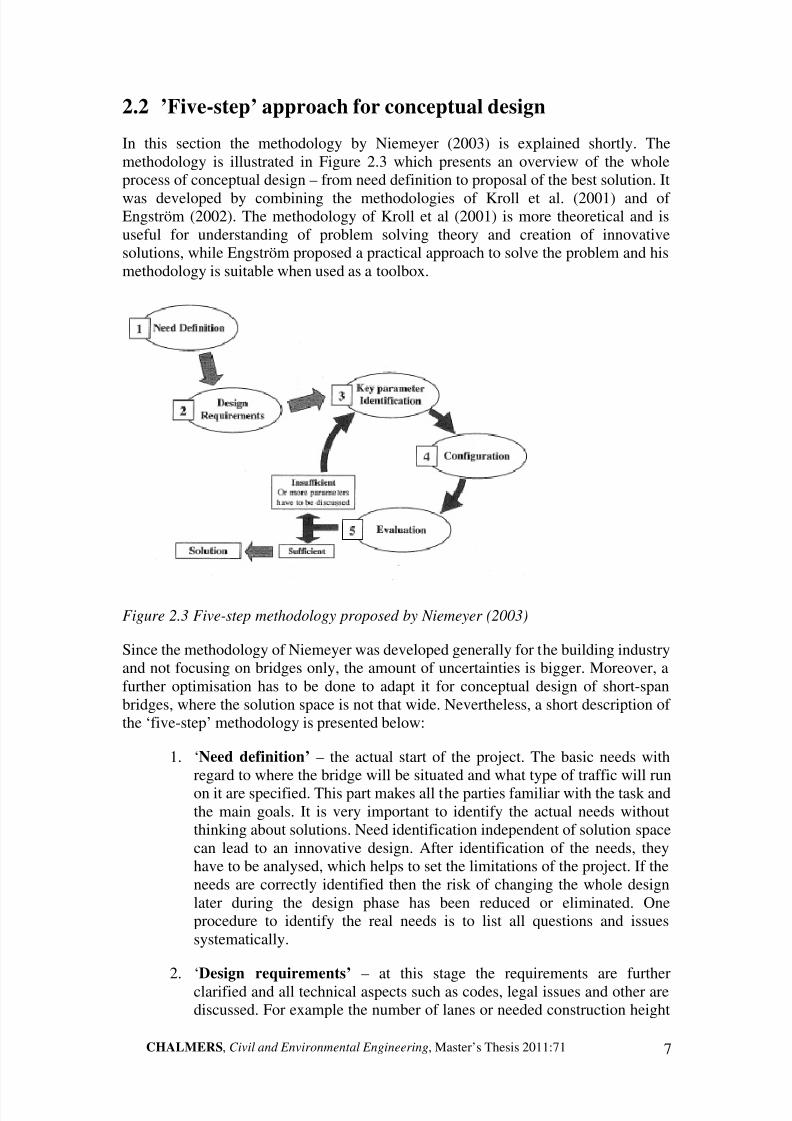
In this section the methodology by Niemeyer (2003) is explained shortly. Themethodology is illustrated in Figure 2.3 which presents an overview of the wholeprocess of conceptual design – from need definition to proposal of the best solution. It
was developed by combining the methodologies of Kroll et al. (2001) and of Engström (2002). The methodology of Kroll et al (2001) is more theoretical and isuseful for understanding of problem solving theory and creation of innovativesolutions, while Engström proposed a practical approach to solve the problem and hismethodology is suitable when used as a toolbox.
Figure 2.3 Five-step methodology proposed by Niemeyer (2003)
Since the methodology of Niemeyer was developed generally for the building industryand not focusing on bridges only, the amount of uncertainties is bigger. Moreover, afurther optimisation has to be done to adapt it for conceptual design of short-spanbridges, where the solution space is not that wide. Nevertheless, a short description of the ‘five-step’ methodology is presented below:
1. ‘Need definition’ – the actual start of the project. The basic needs withregard to where the bridge will be situated and what type of traffic will runon it are specified. This part makes all the parties familiar with the task andthe main goals. It is very important to identify the actual needs withoutthinking about solutions. Need identification independent of solution spacecan lead to an innovative design. After identification of the needs, theyhave to be analysed, which helps to set the limitations of the project. If theneeds are correctly identified then the risk of changing the whole designlater during the design phase has been reduced or eliminated. Oneprocedure to identify the real needs is to list all questions and issuessystematically.
2. ‘Design requirements’ – at this stage the requirements are furtherclarified and all technical aspects such as codes, legal issues and other arediscussed. For example the number of lanes or needed construction height
8/2/2019 Guidelines for Conceptual Design Short Span Bridges
http://slidepdf.com/reader/full/guidelines-for-conceptual-design-short-span-bridges 20/131
8 CHALMERS, Civil and Environmental Engineering, Master’s Thesis 2011:71
is specified. All these are called ‘hard’ parameters and every proposedsolution has to satisfy them. This step gives a summary of the minimumneeded functions and constraints. Design requirements do not meanchecking the performance and properties of the product, since this can leadtowards predefined solutions, which again can be a hurdle for innovative
design. Since design requirements guide the design process, the quality of the product is directly influenced by them.
3. ‘Key parameter identification’ – simplification of the task andtransformation of it into a more abstract problem. By identifying the mostimportant points to the client, generation of ideas and solutions is made.These solutions should try to satisfy the key parameters as much aspossible. Simplification is done by depriving the less important factors orremoving those factors, which are not important in the beginning or duringthe conceptual design phase but can be relevant in the later stages.Secondly, trying to solve the most critical problems first is the way to be
able to continue developing the concept further.
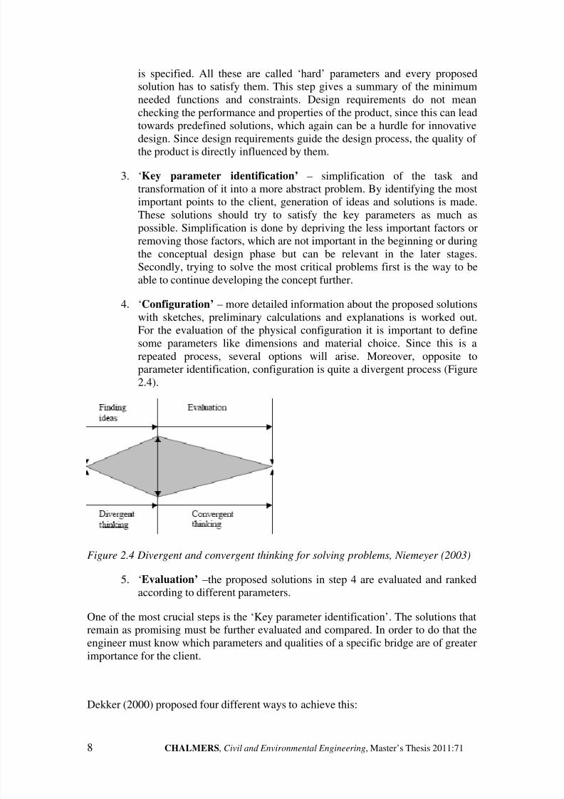
4. ‘Configuration’ – more detailed information about the proposed solutionswith sketches, preliminary calculations and explanations is worked out.For the evaluation of the physical configuration it is important to definesome parameters like dimensions and material choice. Since this is arepeated process, several options will arise. Moreover, opposite toparameter identification, configuration is quite a divergent process (Figure2.4).
Figure 2.4 Divergent and convergent thinking for solving problems, Niemeyer (2003)
5. ‘Evaluation’ –the proposed solutions in step 4 are evaluated and rankedaccording to different parameters.
One of the most crucial steps is the ‘Key parameter identification’. The solutions thatremain as promising must be further evaluated and compared. In order to do that theengineer must know which parameters and qualities of a specific bridge are of greaterimportance for the client.
Dekker (2000) proposed four different ways to achieve this:

8/2/2019 Guidelines for Conceptual Design Short Span Bridges
http://slidepdf.com/reader/full/guidelines-for-conceptual-design-short-span-bridges 21/131
CHALMERS, Civil and Environmental Engineering, Master’s Thesis 2011:71 9
Ranking matrix – all the parameters are compared to each other (Figure 2.5).For each comparison the parameter is given one of three possible values:
+ More important
– Less important
0 Equally important
After this all the values are summed and the parameters ranked. This method givesvery logical outcome by comparing parameters to each other instead of randomlydistributing a number of points between them. However, it requires more time andeffort.
Figure 2.5 Ranking matrix, from Dekker (2000)
Discursive ranking (Figure 2.6) – the different parameters are given a rankingon various scales (1 to 10, 1 to 100) depending on the designer. The choicefollows the needed accuracy or preferences. The most important parameter
receives the highest amount of points and vice versa. If two objectives areconsidered equally important, they should receive an equal score.
10 B
9
8
7 C
6
5 D
4 A3
2 E1
Figure 2.6 Discursive ranking, from Dekker (2000)
Distribution of values using fixed number of points (Figure 2.7) – thisapproach distributes a limited amount of points among the parameters. Again,it is up to the designer to decide how much importance is put on differentparameters, while considering the project specific demands.

8/2/2019 Guidelines for Conceptual Design Short Span Bridges
http://slidepdf.com/reader/full/guidelines-for-conceptual-design-short-span-bridges 22/131
10 CHALMERS, Civil and Environmental Engineering, Master’s Thesis 2011:71
Figure 2.7 Distribution of values using a fixed number of points, from Dekker (2000).
Here 100 points are distributed between parameters A, B, C, D, E.
Objective tree (Figure 2.8, 2.9)) – the most analytical approach, whichprovides more consistency. Here different levels of parameters are present andonly small groups of parameters are compared to each other. The relativeweight of a parameter is related to the relative weight of the group of parameters to which it belongs.
Figure 2.8 Objective tree, from Dekker (2000)
Figure 2.9 General view of the objective tree, from Dekker (2000)
The choice of method depends on the decision of the designers and is not influencingsubstantially the final results. More important is to take into account that differentparameters have different importance for a certain project. For some cases quickermethods such as distribution of values using fixed number of points or discursive

8/2/2019 Guidelines for Conceptual Design Short Span Bridges
http://slidepdf.com/reader/full/guidelines-for-conceptual-design-short-span-bridges 23/131
CHALMERS, Civil and Environmental Engineering, Master’s Thesis 2011:71 11
ranking are suitable, while when detailed analysis – objective tree and ranking matrixgive better results. According to Dekker (2000), the following factors may affect thechoice of evaluation method:
Available time for evaluation
Required accuracy of the comparison
Information available
Complexity of the problem
Preferences of the designer or the team of designers
Finally, it is very important to do an evaluation of the results subjectively and analysethe winning alternative. The highest score does not necessarily mean the best option.
2.3 Overview of demands for bridges
Every structure has to meet a wide range of demands. Six main areas were outlined byEngström (2002) for buildings in general and further adapted for bridges by theauthors. They are systemised in Figure 2.10 below.
Figure 2.10 Demand tree
2.3.1 Technical demands
These are normally the fixed requirements – they always must be fulfilled andsatisfied. The most basic one is the structural load-bearing capacity (resistance) – the

8/2/2019 Guidelines for Conceptual Design Short Span Bridges
http://slidepdf.com/reader/full/guidelines-for-conceptual-design-short-span-bridges 24/131
12 CHALMERS, Civil and Environmental Engineering, Master’s Thesis 2011:71
bridge must be safe to use and remain solid and robust and no collapse or partialcollapse should happen during the whole lifespan. Moreover, all the imposed loadsand other actions must be resisted in a controlled way, i.e. without excessivedeflections, vibrations or settlements – serviceability requirements. For example arailway bridge must have limited settlements and deflections as the railway traffic is
sensitive to movements and has low tolerances.
Most of these demands and requirements are well described in the codes – recentlymade compulsory Vägverket (2009) (TK Bro) and the complementary Swedishspecification Vägverket (2004) - BRO 04. In these documents a lot of other aspectsand requirements are listed as well. Every country has their own codes for design,which engineers strictly follow.
2.3.2 Architectural demands
Aesthetics play an important role in human lives, although often this aspect is either
neglected or unrecognised. As bridges, even short-span ones, are human sculptures ata larger scale, they affect our emotions as we interact with them on a daily basis.Furthermore, most often a bridge is designed for a lifespan of at least 100 years, so itwill be a part of the built environment for a very long period. That is why it is theengineers’ task to satisfy these delicate and subjective demands.
According to Leonhardt (1990), characterising the aesthetic qualities leads toguidelines for designing. Indeed he mentions the following: fulfilment of purpose-function; proportion; order; refining form; integration into environment; surfacetexture; colour; character; complexity and incorporating nature.
Engström (2010) has proposed three very simple yet fundamental tools to achieveattractive tectonics:
Profiling – the shapes follow the force flow and load transfer; material isplaced only where needed by mechanical demands
Inner balance – the bridge is approached as a whole entity
Differentiation – each material or element is used only where it is effective.This creates readability and follows the maxima ‘everything ingenious issimple’
Fitting the bridge into the environment (Figure 2.11) and landscape is a part of aesthetics in general. However, for bridges it is a very significant aspect of theappearance of the structure and that is why it should be separated. Often the bridgesare placed in the countryside so their contact with nature defines this fit. On thecontrary, residential and other buildings have the urban environment to merge with. Inorder to integrate the new bridge smoothly not only the superstructure type andgeometry are important. Secondary parameters such as shadows, colour match andline continuation play an unconscious role in our perception. Bridges should notimpose themselves – they have to find their place in the surrounding space like apuzzle piece. All this can be achieved by the help of landscape architects and partly
by road engineers.

8/2/2019 Guidelines for Conceptual Design Short Span Bridges
http://slidepdf.com/reader/full/guidelines-for-conceptual-design-short-span-bridges 25/131
CHALMERS, Civil and Environmental Engineering, Master’s Thesis 2011:71 13
Figure 2.11 Concept of a landscape bridge, fitting the environment, from
http://www.tallbridgeguy.com
Apart from fitting in the environment and aesthetics, accessibility is anotherarchitectural demand. However, it is mostly concerning pedestrian or fauna1 bridges
or bridges with very complex functions (internal bridges, links between buildings andso on).
The reader is encouraged to find out more information and guidelines for theaesthetical and architectural features of bridges in Leonhardt (1990) and Gottemoeller(2004).
2.3.3 Production demands
The conceptual designer and his or her team need to consider and take into accountthe location where the new bridge will be built. Local constraints such as lapse of well
experienced and equipped contractors can significantly affect the design. Forexample, a very innovative FRP (carbon-fibre reinforced) deck is not a feasiblesolution in detached regions with only local construction companies. On the contrary,new reinforcement methods such as prefabricated ‘rolled’ reinforcement (see Figure2.12) can save up to 90% of placing costs and 40% of reinforcement costs (Bamtec,2011). They do not require skilled labour and are fast and easy to accomplish. Thelocal situation also affects the choice of construction technology especially for largerprojects. That is why it is very good for the designer to know who will be thecontractor beforehand or at least have an idea of the possibilities. Last but not least,restriction in building time has quite an important influence on the choice of thestructural system and especially the main material. For example, a pedestrian overpass
over a railway line must not stop or affect the railway traffic and a prefabricated steelor timber bridge would be very suitable as to avoid extensive false work and work onsite.
1 Fauna bridge - a special type of bridge designed for continuation of natural environment (flora andfauna populations), designed to prevent dividing of natural habitats and assure a natural pass over thenew road or railway.
8/2/2019 Guidelines for Conceptual Design Short Span Bridges
http://slidepdf.com/reader/full/guidelines-for-conceptual-design-short-span-bridges 26/131
14 CHALMERS, Civil and Environmental Engineering, Master’s Thesis 2011:71
Figure 2.12 Prefabricated ’rolled’ reinforcement (Bamtec 2011)
2.3.4 Economical demands
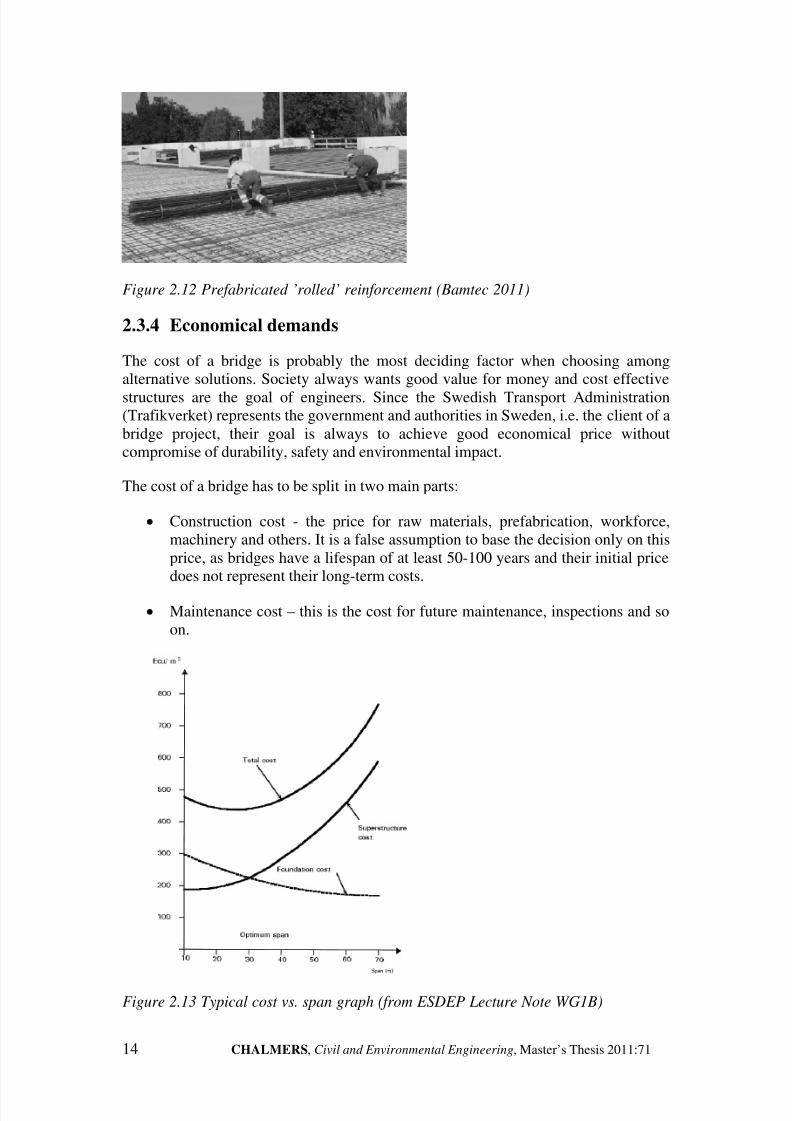
The cost of a bridge is probably the most deciding factor when choosing amongalternative solutions. Society always wants good value for money and cost effective
structures are the goal of engineers. Since the Swedish Transport Administration(Trafikverket) represents the government and authorities in Sweden, i.e. the client of abridge project, their goal is always to achieve good economical price withoutcompromise of durability, safety and environmental impact.
The cost of a bridge has to be split in two main parts:
Construction cost - the price for raw materials, prefabrication, workforce,machinery and others. It is a false assumption to base the decision only on thisprice, as bridges have a lifespan of at least 50-100 years and their initial pricedoes not represent their long-term costs.
Maintenance cost – this is the cost for future maintenance, inspections and soon.
Figure 2.13 Typical cost vs. span graph (from ESDEP Lecture Note WG1B)

8/2/2019 Guidelines for Conceptual Design Short Span Bridges
http://slidepdf.com/reader/full/guidelines-for-conceptual-design-short-span-bridges 27/131
CHALMERS, Civil and Environmental Engineering, Master’s Thesis 2011:71 15
A very big part in the cost of a new bridge is due to the foundation. Indeed, for shorterspans the price of foundations is a relatively large part of the total price. That is whythe engineers always prefer solutions with as little ground works and extensivefoundations as possible. All this can be clearly seen in Figure 2.13 although thisexample is for viaducts. One example is choice of number of spans. Usually it is
cheaper to choose longer spans rather than increase their number. Even though longerspan length results in higher deadweight and construction height, more spans meanmore foundations and piers which directly affect foundation costs and probablybuilding time. Another important aspect for good economical efficiency is time forconstruction and manufacturing. As time equals money, the faster the product iscompleted, the faster the investment can pay off. These demands can steer the choiceof a concept to a prefabricated solution rather than to built in-situ one.
The risk of cost overrun is another factor in bridge construction, which has beenstudied by Flyvbjerg et al. (2002). The average cost overrun in bridge constructionwas found to be 34%. This shows that it can be better to choose a more expensive
solution, but with higher initial quality and less risk of cost overrun.
2.3.5 Service life demands
As mentioned in Section 2.3.4, maintenance cost is a very important parameter whendesigning a new bridge. Service life demands include as little unforeseen repairs aspossible. This is achieved with a proper service life design which includes suitable useof materials and details, plan for maintenance and inspections etc. For example a steelsolution needs periodic painting, while a timber bridge needs careful initial detailingof joints to avoid serious problems. Different materials and production techniquesachieve the required durability and service life demands in different manner and cost.
For example, it is considered that timber bridges satisfy those at a higher cost. Theproblem is not only technical but sometimes political. A chemical protection called’Creosote’ is vastly used in Norway and Finland to protect timber bridges and ensuretheir life span. However, it is not allowed by the Swedish authorities due toenvironmental and health risks. This fact shows that traditions and politics haveinfluence on the choice of bridge type and its design. The mentioned example pointsout that some demands are interconnected – use of ’Creosote’ is due to service lifeconsiderations, but is restricted by the environmental demands. To sum up, servicelife design should be done in a way to assure the safety and serviceability of thebridge throughout its life span.
2.3.6 Environmental care and sustainability
Nowadays bigger and bigger stress is put on sustainability in every aspect of life andconstruction plays a big role (40%) in the cause of pollution and use of naturalresources. New requirements are being imposed for bridges, such as possibility torecycle the bridge, easy disassembly or energy saving production technology. Lifecycle management and costs are considered. In many cases there are environmentalspecialists in the design teams who reflect the needs and restrictions in order to ensureas small environmental impact as possible. These restrictions influence wastedisposal, contamination of land and water, flora and fauna considerations and so on. Atypical example is that in Sweden it is tried to avoid works in the water, while
building bridges. Not only because special permission is often needed, but alsobecause of increased risks and difficulties for the construction. This demand

8/2/2019 Guidelines for Conceptual Design Short Span Bridges
http://slidepdf.com/reader/full/guidelines-for-conceptual-design-short-span-bridges 28/131
16 CHALMERS, Civil and Environmental Engineering, Master’s Thesis 2011:71
(constraint) leads to avoiding some solutions with extensive formwork or casting of middle supports in water. In the Swedish design practice, the engineer receives a mapof the area for the future road and/or bridge (see Figure 2.14). This map includesinformation for existence of endangered species, protected fauna or flora, watersources and other.
Figure 2.14 Map of environmental aspects (Ramböll)
2.4 Current practice in Sweden
The conclusions presented in this section are mostly based on Dekker (2000) and theinterviews conducted with engineers working with conceptual design of bridges.Although Dekker (2000) covered concrete structures and buildings in general, most of the conclusions and remarks are also valid for bridges.
2.4.1 Swedish building industry
In general, conceptual design of short-span bridges is mostly based on experience of the engineers and their continuous dialogue with the client. The predominant client forbridges in Sweden is the Swedish Transport Administration. As a result, Dekker(2000) concludes that a quite good communication between designer and client existsand the conceptual design process is following traditions. Indeed traditions play a vitalrole as around 90% of the bridges in Sweden are made from concrete. Indeed,Harryson (2002) states: ‘the heritage from the craft-based 19
thcentury is still strong
in Swedish bridge construction’.
Critical issues for the design engineer are restrictions with regard to time and money.The initial cost of the bridge is the most deciding factor for the client, since themaintenance cost represents a very small part of the whole price (around 10%). Oneof the reasons why the initial cost is governing is that infrastructural projects arefunded only by the budget and not by any additional incomes such as highway tollsand others. Moreover, the goal of the authorities is to achieve more bridges at lowercost, rather than less but with innovative design or aesthetical and/or otheradvantages. This makes conceptual design of bridges simpler compared to other typesof structures (buildings, facilities and etc.). This is mostly because of the fact that the’client’ is always the same organisation and the requirements are well-known even inadvance. Moreover, the Swedish Transport Administration has a long experience in
maintenance and operation of bridges and is therefore a very competent client. Eventhough the Swedish Transport Administration employs bridge specialists as technical

8/2/2019 Guidelines for Conceptual Design Short Span Bridges
http://slidepdf.com/reader/full/guidelines-for-conceptual-design-short-span-bridges 29/131
CHALMERS, Civil and Environmental Engineering, Master’s Thesis 2011:71 17
staff members (on the contrary of private residential houses where the ’client’ usuallylacks sufficient technical knowledge), the client’s representative is not alwaystechnically experienced.
Apart from these aspects, an important circumstance exists in the building industry in
Sweden and it is related to the type of contract, which is commissioned:
‘Total contract’ – in this case the contractor has big freedom and is responsiblefor the design and construction of the object (bridge). Often the client oftenhas no clear vision and specified requirements. This is why the clientcommissions a consultancy in order to receive help in forming the frames andrequirements for the contractor. The most important factor for conceptual anddetailed design is the total cost of the bridge. The two latest conditions lead tolimited options and freedom for the designer (consultant). This is because it isthe contractor that designs and builds the structure. That is why the cheaperthe initial cost is, the better profit will be achieved.
‘General contract’ – here the contractor only produces the already designedstructure with little or no influence on the final product. The client in Swedenis almost exquisitely the Swedish Transport Administration and the task isusually not only conceptual design but detailed design as well. After thedetailed design is completed, a contractor is found to build the bridge.’General contract’ is the most common form and allows for more freedom forthe designers in conceptual design. On the contrary, the contractor is restrictedmore. This type also has bigger focus on the overall function of the new bridgeand takes into account broader aspects.
These different contract forms result in quite different conditions for the conceptualdesign of buildings. On the contrary, bridge engineering often falls in between boththese contract forms and this varies according to the project. For large scale project(motorways, railways) the authorities often commission a whole stretch to thecontractor who usually sub-commissions consultants for the design. On the otherhand, for smaller junctions and roads for example, an approach closer to ‘Generalcontract’ is used. Then, the client has a clear idea of the new bridge and theconceptual design consists of providing a solution that satisfies regulations and theclient’s demands best.
The conclusion is that conceptual design for short-span bridges is not directly affected
by the type of contract. The same procedures and methodologies can be used nomatter of the case. Moreover, bridges represent a specific type of structures and oftenthe contract cannot be described as ’Total’ neither as ‘General’ contract. Most oftenthe projects are somewhere in between these two options.
2.4.2 Conceptual design in consultancies
Conceptual design is approached differently by each consultancy and also eachengineer. Most often conceptual design starts with a brainstorming session comprisingof different specialists. A bridge is not an isolated structure and it has to be integratedwith the road, landscape and environment. Hence, the bridge engineer starts the work
in coordination with road designer, geotechnical engineer and landscape architect,especially for larger projects. Moreover, the society demands safe, economical and

8/2/2019 Guidelines for Conceptual Design Short Span Bridges
http://slidepdf.com/reader/full/guidelines-for-conceptual-design-short-span-bridges 30/131
18 CHALMERS, Civil and Environmental Engineering, Master’s Thesis 2011:71
quick solutions with good aesthetical features. That is why the designer alwaysevaluates and assesses different options, while keeping in mind the requirements anddemands of the client (society). To identify and understand these demands, theengineers carry out numerous meetings with the clients and between each others.Since economy is one of the most important parameters of the project, it acts as
decisive for the conceptual design of bridges. Therefore, design engineers always tryto think in a way such that the most economical solution is achieved. This is done byconsidering different factors: availability of material and skilled labour, structuralefficiency and good detailing to minimize the required maintenance etc. Hence, byhaving strong practical knowledge, designers consider production methods andcommercial aspects of the project. The overview of the designer puts together all theinformation and the input thus providing proposals for economical and efficientsolutions. In addition, there are often further specific project requirements, whichhave to be considered. Similarly, availability of working space at the site,environmental considerations and type of obstacle are some examples of siteconditions or constraints.
Only half of the interviewed engineers stated that had a certain procedure forconceptual design (Dekker (2000)). Most often this procedure includes the use of checklists in order to keep track of the work and to avoid missing some aspects.Depending on the project, consultants come up with a number of promising solutionsand maybe propose the best one according to their experience. This selection ismostly done by means of discussions and rarely using more complex evaluationmethods such as evaluation matrixes, usage-value analysis or controlled convergence(explained in Section 2.2). The final presentation of the proposed solution to the clientis made mostly be means of an oral description with optional graphs. An importantaspect is that the client knows roughly the solution as a result of the discussions and
meetings during the conceptual design phase. This shows the iterative nature of conceptual design.
Swedish authorities are constantly issuing literature in forms of architecturalguidelines and other publications. The most used ones concerning bridge design aretwo handbooks called Bridge design ( Broprojektering) – one from the Swedish RoadAdministration (Vägverket 1996:63) and one from the Swedish Rail Administration(Banverket, 2007). They cover general aspects and technical details as well as themost common bridge types. In addition to these, there is a separate specificationtreating bridge design – TK Bro (Vägverket publ. 2009:27). It provides very detailedinformation, especially for further stages of design. With the introduction of Eurocode
in all EU nations, new trends are arriving. Some solutions that were not allowed byprevious National rules are now permitted and other aspects are changing. Forexample composite solutions consisting of timber beams and concrete deck are nowallowed by Eurocode, thus probably giving the engineers a chance to explore it.
A summary of opinions of how to improve and optimise the conceptual designprocess is presented below (Dekker (2000)):
Further implementation of Building Information Modelling (BIM) and othermethods of documenting previous experience
Better integration between Final Elements Analysis (FEA), Computer-aideddesign (CAD) and structural software

8/2/2019 Guidelines for Conceptual Design Short Span Bridges
http://slidepdf.com/reader/full/guidelines-for-conceptual-design-short-span-bridges 31/131
CHALMERS, Civil and Environmental Engineering, Master’s Thesis 2011:71 19
More time and resources should be devoted to conceptual design
More education of the staff on conceptual design
In the current high-tech world, the construction business and particularly design
seems to be somewhat behind other industries, for example automotive or electronic.This is why leadership and company policy have to be adapted to the changing worldso that consultancies remain competitive on the market. Use of VR1 models can alsohelp to give an idea of the bridge and how it fits into the surrounding landscape. Thus,different alternatives can be evaluated and compared and a better understanding canbe achieved both for the designer and the client
More detailed information about the conceptual design in Sweden can be found inDekker (2000).
2.4.3 Common problems faced
According to Dekker (2000), the biggest problem engineers (60%) face while creatinga solution for a bridge is the lack of time for finding the most optimal solution. Oftena too short time period is available for conceptual design and naturally engineers tendto look back at previous projects or use their own experience in order to quicklyprovide reliable and cost effective solutions. Only half of the interviewed engineersanswered that they use a structured procedure for conceptual design, Dekker (2000).
Consequently, during the interviews carried out by the Authors, it became clear thatthe engineers tend not to remember all of the alternatives they had in mind and reckononly the final conceptual proposal. Another discovered issue was the difficulties when
estimating and reasoning the cost of a new structure both for construction andmaintenance. Knowledge in this area is restricted and as in every other market areathe economic situation changes constantly (price of raw materials, labour, machineryetc.). Unclear initial vision and vaguely described demands of the client also causeproblems for the engineer. Sometimes it is difficult to really understand what theclient demands and what are his or her priorities. This is also different depending onthe person representing the client. The changes in requirements and demands duringthe project affect engineers’ work significantly, but this effect is not alwaysunderstood by the clients. Another reason for late changes of the concept is moredetailed geological information, which arrives overdue during the conceptual designprocess or at even later stages.
Finally, most of the interviewed specialists agreed that conceptual design can beimproved and that experience from previous projects needs to be organised better andreused more efficiently, Dekker (2000).
1 VR – Virtual Reality

8/2/2019 Guidelines for Conceptual Design Short Span Bridges
http://slidepdf.com/reader/full/guidelines-for-conceptual-design-short-span-bridges 32/131
20 CHALMERS, Civil and Environmental Engineering, Master’s Thesis 2011:71
2.5 Practical lessons learned from the ‘Virserum’ timberbridge
During the spring of 2010, the author participated in a timber bridge engineeringcompetition, which was organised as a joint-work with master’s students from bothArchitecture and Engineering and Civil Engineering at Chalmers University of Technology (Figure 2.15). A part of the task was to design a timber bridge for the‘Virserum’ wood exhibition, which was to be held in the summer of 2010 in thevillage of Virserum, Sweden. This event takes place every three years and attractsthousands of visitors from Sweden and other countries.
Figure 2.15 Discussion on the concept
Figure 2.16 The site
The focus of this section is on the ’real world’ experience during conceptual andpreliminary design and construction of the 9 m spanning ‘Virserum bridge’ and not onthe competition itself. More detailed information about the whole competition can befound in Tosi (2010). Because of the fact that the team consisted of 10-12 students –both structural engineering and architectural students – the dialog started from thevery beginning.

8/2/2019 Guidelines for Conceptual Design Short Span Bridges
http://slidepdf.com/reader/full/guidelines-for-conceptual-design-short-span-bridges 33/131
CHALMERS, Civil and Environmental Engineering, Master’s Thesis 2011:71 21
The work started with defining the needs and requirements of the client. Below is ashort summary of them and into which area each demand falls:
Good aesthetics and appearance should be strived for as this is an international
exhibition on wooden and timber products - Architectural
The solution must be as cheap as possible since the client (exhibition
organiser) financed the project himself - Economical
The whole construction process should be finished within 3 days by the
students themselves (Figure 2.18) - Production
The bridge should be made primarily of timber, while using only screws, nails
and few bolts and metal connectors - Production
The bridge’s weight must not exceed 600-700 kg since this was the capacity of
the crane - Production
In addition, during the design phase there was a constant inflow of new
information and need of changes from the client due to different reasons –
Technical/Production
It was decided to place the bridge next to the existing one (Figure 2.16) -
Production
To start with, the work began with developing concepts and visions for the new
bridge. Collaboration and dialog during that process were significant and each aspectwas criticised thoroughly from structural as well as aesthetical points of view. Duringthe conceptual design, three different concepts were established and evaluated(Figure 2.17). However, no guidance or tools were used; on the contrary, everythingdepended on architectural feeling and previous experience. At this stage it was thearchitects challenging their creativity rather than thinking more practically. It becameevident that the more simple and proven solution engineers argued for, the moreuninspiring and boring it looked. The conclusion is simple: as everything in nature, abalance has to be achieved. It can be achieved with a holistic view and understandingof structural art and its consequences on the society and environment. Due to thenature of this project, conceptual design was a longer process as it was not a
mainstream solution and had to be built by the students during three days. Being apedestrian bridge it gave a lot of freedom to experiment with shapes and design.
The final decision on, which concept to continue with was made after a critiquesession from practising architects and the choice of the client. The chosen conceptwas the ‘V bridge’ mainly because of it is practicality and feasibility of constructioncompared to the other possibilities.

8/2/2019 Guidelines for Conceptual Design Short Span Bridges
http://slidepdf.com/reader/full/guidelines-for-conceptual-design-short-span-bridges 34/131
22 CHALMERS, Civil and Environmental Engineering, Master’s Thesis 2011:71
Figure 2.17 The three proposals established during conceptual design phase
Figure 2.18 During construction
Consequently, the construction begun and immediately various issues emerged. Theinitial choice of 4 main glulam beams had to be dramatically changed – due to a delayin delivery, the team had to rethink and redesign the main load-carrying system. Thisshows the need for margins of flexibility that have to be included in the design, sincein almost every project there are deviations from the original design. The mainstrategy in those situations is to improvise and try to stick to the main idea behind theconcept chosen. The obstacle for this bridge was a small river and the bridge’srobustness and rigidity of connections were crucial. Although some calculations forthe main joints were done, the engineers’ ’feeling’ and rules of thumbs were used.Even though it was not the most efficient way, it provided the needed safety.
Some important aspects were recognised in the late stages of the building process (seeFigure 2.18). Due to the eccentric cross-section (Figure 2.19) and loading, the bridgewas designed to work in torsion and was fixed at both ends by anchoring bolts. Sincethe structure was already placed and anchored, one big weakness was discovered – thebridge’s torsional stiffness was not sufficient even though the bridge had diagonalsbetween the lower flanges and was a trussed box. Bracing was added in the upperflange and the problem resolved successfully. The lesson learned is that if morethorough study had been carried out in the preliminary stage, this unforeseen problemcan have been avoided. This perfectly reflects the relationship later change - biggercost. In this case the cost was the extra time resource spent.

8/2/2019 Guidelines for Conceptual Design Short Span Bridges
http://slidepdf.com/reader/full/guidelines-for-conceptual-design-short-span-bridges 35/131
CHALMERS, Civil and Environmental Engineering, Master’s Thesis 2011:71 23
Figure 2.19 Cross-section with load distribution
Conclusions:
The collaborative work between architects and engineers gave a great balancebetween aesthetical impact and structural robustness
Developing concepts only by architects was probably not the best way sincethey do not always have a deep understanding of how bridges work structurally
Flexibility in the design is important, as it allows for unforeseen changesduring later stages
Designing and constructing a bridge even for a temporary use proved to be a
very challenging and exciting task both for engineers and architects
Production demands turned out to be the most influencing on the concept
While the load-carrying system is well-known, the details (carpentry, flexiblerailings and visual effects) and the specific unsymmetrical shape gave thebridge a unique presence (Figure 2.20).
Figure 2.20 The completed bridge

8/2/2019 Guidelines for Conceptual Design Short Span Bridges
http://slidepdf.com/reader/full/guidelines-for-conceptual-design-short-span-bridges 36/131
24 CHALMERS, Civil and Environmental Engineering, Master’s Thesis 2011:71
2.6 Conditions and constraints affecting bridge design inBulgaria, Pakistan and worldwide
Engineering and bridge design vary from country to country due to various factorssuch as traditions, economical and political situations or local geographicalconditions.
The main aim of bridges is to transport traffic of people and goods – road, railway,pedestrian or other. To accomplish this task, bridges must be able to withstand theloads imposed by this traffic and every other action like wind, snow, frost, seismicetc. Dynamic loads from earthquakes in particular play a very significant role indesign of structures in areas where seismic action is common and has substantiallevels. The above mentioned facts affect the conceptual design of bridges as well. Forexample, in order to accommodate for big accelerations and movements, simplysupported bridges are preferred so that these imposed displacements can be takenwithout excessive restraint stresses. Moreover, ductile materials such as steel are
preferred as they allow for plastifisation and can resist the action with largerdisplacements without collapsing in case of a high magnitude earthquake. This iscompletely opposite to the practice in Sweden (which lies in non-seismic area), whereconcrete frame bridges are extremely common solutions. A single pier middle support(Figure 2.21) is a very inappropriate solution in seismic areas as it is not effective toresist the big dynamic forces only by bending stiffness of the column. This showsanother difference between solutions in seismic areas and the Swedish practice whereone column (pier) is a quite common solution.
Another example is areas with strong winds – tornados, hurricanes and so on. Theengineer will most probably opt for heavier bridge structures to prevent them from
being displaced by the extreme wind pressures. Choosing a light timber bridge mightbe good if it is a standardised cheap solution in a similar fashion like residentialhouses in tornado areas in USA – already in the concept it is decided to build a timberhouse and rebuild it after the disaster rather than going for an expensive solution,which is designed to resist the forces of the nature. These two examples show howsignificantly conceptual design can be affected by local geographical conditions.
Economical and political situations affect bridge design as well. If a country issuffering from economical crisis, it cannot afford to experiment with innovativebridge designs or new construction methods. In addition, political system also shapesthe construction industry. In the Soviet block most of the research was done into
optimisation and unification of structures and the result was a lot of traditions andexperience in prefabricated presstressed concrete beam bridges. This, combined withseismic action, has lead to the fact that the majority of highway bridges in Bulgariaare prefabricated concrete beams.

8/2/2019 Guidelines for Conceptual Design Short Span Bridges
http://slidepdf.com/reader/full/guidelines-for-conceptual-design-short-span-bridges 37/131
CHALMERS, Civil and Environmental Engineering, Master’s Thesis 2011:71 25
Figure 2.21 Single pier
Types of Bridges Used in Pakistan
In Pakistan many types of bridges have been constructed ranging from slab bridges totruss bridges spanning more than 60 meters. Similarly to the rest of the world, theselection of a certain bridge type is greatly influenced by the type of loading and siteconditions. Many other factors like political influence, aesthetics or importance on thebasis of defence, play important roles in bridge design. Sometimes bridges aredesigned for military loading if they are located in areas under military jurisdiction.
If we try to generalise the bridges according to the type of traffic they carry, thenroad, railway and pedestrian bridges are usually found in Pakistan. In road bridges,concrete is the most preferable material because steel and timber are expensive inPakistan as compared to the rest of world. Reinforced concrete slab bridges,
reinforced concrete beam-slab bridges and prestressed concrete bridges are found,usually with a span range up to 30 meters. The substructure’s design is greatlyaffected by the subsurface conditions and elevation. Piles with transom1 have been acommon solution of the substructure during the past decade. For railways, PakistanRailways usually applies one of the following structural systems: reinforced concreteslab, steel I-girders with concrete deck, steel trusses and prestressed box girders. Incase of pedestrian bridges concrete and steel structures are still the most commonoption. Unlike Sweden, where wood is cheaper and with better quality, timberpedestrian bridges are not common in Pakistan.
Some bridges are designed keeping in mind some special circumstances. For examplethe Colander Hamilton Bridge2 type is used for temporary solutions in case of emergent bridge replacement and for construction by military engineering units.Under current bridge design practice, conceptual design is highly influenced by thefact that Pakistan is situated in an earthquake zone along with flood hazard. Of this
1 ‘transom’ are deep beams which rest on composite piles and transfer the load from thesuperstructure to the piles
2 The Colander-Hamilton Bridge is a modular portable pre-fabricated steel truss bridge.

8/2/2019 Guidelines for Conceptual Design Short Span Bridges
http://slidepdf.com/reader/full/guidelines-for-conceptual-design-short-span-bridges 38/131
26 CHALMERS, Civil and Environmental Engineering, Master’s Thesis 2011:71
reason concrete frame bridges are not a common solution for short-spans in Pakistan,unlike Sweden.
2.7 Summary
Conceptual design is the most creative part of bridge engineering, but at the same timeprobably the most demanding. It requires experience and broad knowledge of all areasconnected with bridges – from legal aspects, to technical details and ability to extractand understand the needs of the client. Most often the problem is open and it is thedesigner’s responsibility to find the most appropriate solution. Even thoughconceptual design is known for centuries, there is still a lack of helpful guidelines andmethodologies to support the designer. That is why it is very common that theengineer chooses very well-known solutions even without considering other options.The reason for this is mainly shortage of time. However, investing more time inconceptual design will always lead to a more optimal final product.

8/2/2019 Guidelines for Conceptual Design Short Span Bridges
http://slidepdf.com/reader/full/guidelines-for-conceptual-design-short-span-bridges 39/131
CHALMERS, Civil and Environmental Engineering, Master’s Thesis 2011:71 27
3 Classification of the most typical designsituations
This chapter classifies the most commonly met design situations when it comes to
design of short-span bridges. First a more general classification is made and then themost important factors are selected. Although every bridge is unique and everysituation has its specific conditions, this classification provides a good overview andtries to divide the complex problem into simpler ones.
3.1 Methodology and approach
First of all, it is important to think about the needs and demands the society hasconcerning a new bridge. Moreover, the specific site conditions or constraints playimportant roles in developing a concept. It is very easy to make the mistake of thinking not on a concept but on a specific solution (for example a concrete framebridge) straight away. This immediately narrows and restricts engineers view. It isvery crucial to differentiate between the ‘demand’ and the solution. For example, thedemand is to cross the river, but it can be fulfilled by a bridge, a tunnel or a ferry(possible solutions).
Secondly, conceptual design includes much broader perspective and is not onlylimited to the bridge itself. Usually it is a whole stretch of road that needs to bedesigned and the bridge engineer must work in close collaboration with the landscapearchitects, road planners and so on. In Swedish practice the most common situationfor bridges is that a corridor (see the shaded area in Figure 3.1), where the new road
can be placed, is given by the client. This means that the exact place of the bridge isoften not clearly defined and it is the task of the conceptual engineer to take intoaccount all the considerations, not only his specific input about the bridge itself. Dueto the fact that every situation is unique and the problem includes infinite variables,this classification focuses mostly on cases when the place of the bridge is decided.
Figure 3.1 Typical corridor (Ramböll)

8/2/2019 Guidelines for Conceptual Design Short Span Bridges
http://slidepdf.com/reader/full/guidelines-for-conceptual-design-short-span-bridges 40/131
28 CHALMERS, Civil and Environmental Engineering, Master’s Thesis 2011:71
3.2 Classification of demands, constraints and conditions
After the literature studies and talks with specialists, the most decisive types of constraints, conditions or demands were found out. They were selected by theirimportance and although it is not always easy to separate them from each other, the
classification of parameters is fairly logical (random order):
Type of traffic to transport
Ground conditions
Length of the bridge
Type of obstacle to cross
Relation between centre lines of the bridge and the obstacle
Location (position in the environment)
Type of traffic is probably the most important factor for the classification of bridgesbecause design loads, clearances and specific requirements depend on it. Groundconditions affect both the choice of substructure and superstructure. The geotechnicalsituation is the most unknown and unclear of all conditions and requires specialattention. Often a redesign is needed when some more detailed information has beendiscovered. The type of soil affects the choice of material and type of foundationsystem. The scope of this research work is limited to short-span bridges, which are
further classified into three different categories by their length. This refinement isneeded mainly to increase the precision of the method. The classification of length isslightly questionable as it concerns both the demand and the solution. For example,the height of the profile of the road defines the length of the bridge. However it isquite a logical classification. Another important parameter is the type of obstacle forthe bridge to cross and the site plan. Conditions on site can dictate the possibility of placement of middle support. Any physical restriction has to be considered in thegeometric design. Other important parameter is the relation between the centrelineof the future bridge and the obstacle’s. That relation can lead to need of a skewedor curved bridge, which is more complicated and expensive. Finally, location isconsidered: is the bridge located in a congested urban area or outside in the
countryside for example? This affects the aesthetical decisions and consultation witharchitects and landscape architects is needed.
All the above mentioned parameters important for classification of the designsituation together with their most common sub-options are systematised in Table 3.1.

8/2/2019 Guidelines for Conceptual Design Short Span Bridges
http://slidepdf.com/reader/full/guidelines-for-conceptual-design-short-span-bridges 41/131
CHALMERS, Civil and Environmental Engineering, Master’s Thesis 2011:71 29
Table 3.1 Specification of demands, constraints and conditions
A B C D E F(optional)
Type of t raff ic Type of obstacle to br idge Length Ground condit ions Locat ion
Bridge vs
obstacle
1. Road 1. Water- River 1. < 8 m 1. Clay (or cohes. soil) 1. Urban 1.
2. Ped.and bicycle 2. Water- stream, spring 2. 8-18 m 2. Rock 2. Highway 2. skewed
3. Railway 3. Road 3. 18-30 m 3. Frictional material 3. Countryside 3. curved
4 . Fauna (animals ) 4. Railway track
5. Pedestrian passage
6. Fauna passage
Note that combinations of parameters in one column (Table 3.1) are possible andusually present. For example very often a road bridge has a pedestrian walkway or theobstacle is an existing road and a pedestrian pass. Another example can be differentsoil conditions at both ends of the bridge or the inability to define whether the locationis urban or countryside (for example outskirts of a town). For simplicity, all thesecombination and nuances are not reflected. Instead, the focus is on the main type(biggest importance) of parameter for each column, which will govern the finalsolution.
3.3 Refining of design situations and classification
Theoretically there are 1944 possible combinations of the different parameters inTable 3.1, where each combination would represent one type of design situation. Eventhat many, they can still not fully cover all the various situations a bridge engineerfaces in reality. However, the aim of this project was to identify the most commonlymet cases, so the authors needed to further simplify the specification of parametersand based their choice on the information collected beforehand. Table 3.2 shows asimplified specification of parameters.
Table 3.2 Simplified specification of demands, constraints and conditions
A B C D E F(optional)
Type of t raffic Type of obstacle to bridge Ground condit ions Length Locat ion Bridge vs
obstacle
1. Road and/or fauna 1. Water 1. Clay (or cohes. soil) 1. < 8 m 1. Urban 1.
2. Ped.and bicycle 2. Road and/or railway 2. Rock 2. 8-18 m 2. Highway 2. skewed
3. Rai lway 3. Fauna or ped. passage 3. Frict iona l mater ia l 3. 18-30 m 3. Countryside 3. curved
4. Fauna and water
Primary Secondary
Road traffic and fauna (landscape) bridges have certain similarities. As the ground fillfor fauna bridges is present, the dead load is quite similar to that of a road track

8/2/2019 Guidelines for Conceptual Design Short Span Bridges
http://slidepdf.com/reader/full/guidelines-for-conceptual-design-short-span-bridges 42/131
30 CHALMERS, Civil and Environmental Engineering, Master’s Thesis 2011:71
surface. Moreover, the client always wants a versatile structure used for as manypurposes as possible. This leads to fauna bridges with a road lane (see Figure 3.2).The later justifies the combination of both types of traffic. However, a recent trend isdesigning bridges only for environmental purposes and we can expect an increase of these cases in the near future.
Figure 3.2 Fauna bridge with road lane over E6 near Uddevalla, courtesy of Google
maps (2011).
In Table 3.2, column B (type of obstacle), two other simplifications are made. Firstly,all water obstacles are united. The reason behind this is that both represent a similardemand to avoid working in water due to the difficulties and restrictions this wouldimpose. Moreover, water levels vary throughout the year and a small creak canemerge into a small river during the spring season. Unification between road andrailway obstacles is done as well. Apart from some details (fences on the bridge overthe railway line), the biggest difference between them is the free height required –
4.70 m for traffic and 5.9-6.5 m for railway, Vägverket (1996). As it can be seen inTable 3.2, the three primary parameters are type of main traffic, which goes on thebridge, the type of obstacle the bridge crosses and the ground conditions. Thesecondary parameters like length, location and angle alter the resulting solution, butnot that significantly as the primary ones. Length is considered secondary because it isthe engineer’s choice to decide how long the bridges will be – should it cover the gapof obstacle exactly or be longer, allowing for more open view and other advantages.Of course here we still think of bridges with a length less than 30 m according to thescope of the project. Furthermore, a decision to remove the distinction to three lengthintervals was made since this would bring more confusion than benefits. Both thelocation and the relation between bridge and obstacle contribute more to the
architectural and structural demands. The primary parameters needed forclassification of design situations of bridges are summarized in Table 3.3.

8/2/2019 Guidelines for Conceptual Design Short Span Bridges
http://slidepdf.com/reader/full/guidelines-for-conceptual-design-short-span-bridges 43/131
CHALMERS, Civil and Environmental Engineering, Master’s Thesis 2011:71 31
Table 3.3 Primary parameters for classification of the design situation
A B C
Type of traffic Type of obstacle to br idge Ground condit ions
1. Road and/or fauna 1. Water 1. Clay (or cohesive soil)
2. Pedestrian and cycle 2. Road and/or railway 2. Rock
3. Railway traffic 3. Pedestrian passage 3. Frictional material
4. Fauna and water
Primary parameters
The theoretical number of combinations is now only 36, which represents 36 differentdesign situations. The selection of the most common design cases is based on the
primary parameters. The ground conditions, as mentioned before, are very significantand an uncertain parameter. However, it was discovered that for short-span bridgesthey affect mostly the choice of the substructure and not too much the superstructure.Moreover, if the soil is not very good (silt or clay), it is common to remove it andreplace it with frictional material whenever possible and cost effective. The only casewhere ground conditions have a big effect is for bridges with inclined supports orarched bridges. The big horizontal forces are very difficult to accommodate when clayis present and sometimes even for frictional material. Another aspect is that a verylarge amount of the cost is related to the foundation and the width of the foundationslabs.
The final classification of design situations is presented in Table 3.4.

8/2/2019 Guidelines for Conceptual Design Short Span Bridges
http://slidepdf.com/reader/full/guidelines-for-conceptual-design-short-span-bridges 44/131
32 CHALMERS, Civil and Environmental Engineering, Master’s Thesis 2011:71
Table 3.4 Demand cases (design situations)

8/2/2019 Guidelines for Conceptual Design Short Span Bridges
http://slidepdf.com/reader/full/guidelines-for-conceptual-design-short-span-bridges 45/131
CHALMERS, Civil and Environmental Engineering, Master’s Thesis 2011:71 33
4 Different solutions for short-span bridges
This chapter presents most of the possible solutions for short-span bridges, exceptsome special cases such as movable, aircraft, and military bridges and other specific
cases. It includes both common and well-known solutions and some examples of newtrends that can be found worldwide. The aim is to broaden the engineer’s view so thathe or she considers more options. Limitations of the selected solutions are themaximum length of 30 m and that the focus is mostly on the type of superstructure.For simplicity a classification of the solutions is made, mainly by their main materialfor the longitudinal load-bearing system as follows:
Concrete bridges
Steel bridges
Timber bridges
Composite bridges
4.1 Concrete bridges
Nowadays concrete bridges represent almost 90% of the bridges built in Sweden.Similarly, in the rest of the world concrete is as well preferred material in bridgeconstruction especially for shorter spans. The main advantages are lower cost, betterdurability and good traditions in use of this material. The biggest drawbacks are thehigher self-weight, longer construction time, larger labour usage and probably
aesthetical deteriorations after some time. Concrete bridges can also be unpleasantaesthetically because of more a massive outlook and higher construction heights.Colouring and texture also play role in this appearance and solutions already exist toenhance these properties of bridges. In fact, attention to details and texture cantransform concrete bridges to very attractive landmarks. One maintenance demand,similar for all concrete solutions in Sweden, is the need of replacement of edgebeams, which most often must be done two times during the life (80 years) of abridge.
4.1.1 Slab-frame cast in-situ
Figure 4.1 Typical slab-frame concrete bridge, from Vägverket (2006)

8/2/2019 Guidelines for Conceptual Design Short Span Bridges
http://slidepdf.com/reader/full/guidelines-for-conceptual-design-short-span-bridges 46/131
34 CHALMERS, Civil and Environmental Engineering, Master’s Thesis 2011:71
Description: The slab-frame bridge is the most common type of bridge in Sweden(almost 50% of the bridges belonging to the Road Administration (Vägverket) are of this type). It is a very simple and cheap solution for short spans and when crossingnarrower obstacles (roads, pedestrian passes and etc.). It is very effective, since in thistype the sub- and superstructures are united thus acting together. This solution relies
on frame action and the bridge takes earth pressure and imposed loads at the sametime (Figure 4.1). There is no need of bearings and expansion joints, which leads tolower maintenance work. For lengths up to 10 m, usually a full box is designed (aframe with integrated bottom slab), which gives high rigidity and superior loaddistribution to the soil. This quality makes it a good alternative in case of soils withlow bearing capacity. Due to the overall rigidity of this concept, there is a possibilityto cast the bridge beside its future location and slide it in place when ready. Examplesof cross-sections are shown in Figure 4.4.
Optimal span: 4-20 m, above 22 m prestressing is advised (economicallycompetitive).
Span-to-depth ratios: depends on the height of the side walls (Figure 4.2, 4.3).
Figure 4.2 For spans 4-12 m, from Vägverket (1996)
Figure 4.3 For spans 12-25 m, from Vägverket (1996)

8/2/2019 Guidelines for Conceptual Design Short Span Bridges
http://slidepdf.com/reader/full/guidelines-for-conceptual-design-short-span-bridges 47/131
CHALMERS, Civil and Environmental Engineering, Master’s Thesis 2011:71 35
Advantages: This bridge type is possibly the cheapest alternative (especially for shorterspans); economically advantageous for short spans and good ground conditions,Vägverket (1996); low construction height; very long traditions; robustness; cheapand simple formwork and construction; flexibility in shape and design.
Drawbacks: A restriction is needed in angle of skew since it introduces big torsionalmoments, which increases ground stresses; not recyclable.
More information: Vägverket (1996)
Figure 4.4 Examples of cross-section configurations
4.1.2 Beam-frame cast in-situ
Figure 4.5 The beams are fixed into the abutments, from Vägverket (1996)
Description: This bridge type is very similar to the slab-frame bridge described inSection 4.1.1, but suitable for longer spans and wider bridges. Again it relies on frameaction, but here the bridge deck is ribbed (Figure 4.5). There is no need of bearingsand expansion joints, which leads to lower maintenance w. However, most oftenprestressing is used and this increases the price. Very rarely it is designed as a multi-span bridge. The same recommendations as in Figures 4.2 and 4.3 apply.
Advantages: This bridge can easily achieve longer spans; robustness; mechanicallyefficient shape; flexibility in shape and design.

8/2/2019 Guidelines for Conceptual Design Short Span Bridges
http://slidepdf.com/reader/full/guidelines-for-conceptual-design-short-span-bridges 48/131
36 CHALMERS, Civil and Environmental Engineering, Master’s Thesis 2011:71
Drawbacks: It is not very cost efficient in the span range below 30 m; not recyclable;higher construction height compared to the slab-frame alternative; more expensivethan the slab-frame bridge due to complex formwork and prestressing (if present).
Optimal span: 24-40 m; economically competitive >20 m
Span-to-depth ratios: n.a.
More info: Vägverket (1996)
4.1.3 Integral abutments (jointless bridges)
Figure 4.6 Principal scheme from Allen, C. et al. (2008)
Description: This methodology of constructing bridges is a rather new approach andhas been used in Sweden only for a pilot project. However, in Northern America it isalready a common solution. The main idea is to avoid the cost of bearings and
movement joints between the sub- and superstructures (Figure 4.6).The deck structurecan be of concrete or steel, but concrete is mostly preferred (timber is not effective).Here this bridge type is put under the heading concrete bridges as concrete solutionsare most common in this system.
According to Allen, C. et al. (2008):’The primary difference between an integral abutment bridge and a conventionalbridge is the manner in, which movement is accommodated. A conventional bridgeaccommodates movement by means of sliding bearing surfaces. An integral abutmentbridge accommodates movement by designing each abutment to move unrestricted asa result of longitudinal loading effects with less induced stress, thus permitting the use
of lighter and smaller abutments.’
A conventional elastic analysis cannot represent how the loads are resisted. Integralabutments are suitable for single spans no longer than 44 m using a ‘Simplified designmethod’, Allen, C. et al. (2008). This design approach is not in line with Swedishstandards, but can be guiding.
Advantages: This bridge type has reduced initial and lifecycle costs, due to jointlessconstruction; lighter and smaller abutments; shorter time for foundation constructioncompared to traditional piling; can be used for single and multiple span bridges; canresist uplifting forces; higher redundancy; no tolerance problems (as no joints and
bearings exist).

8/2/2019 Guidelines for Conceptual Design Short Span Bridges
http://slidepdf.com/reader/full/guidelines-for-conceptual-design-short-span-bridges 49/131
CHALMERS, Civil and Environmental Engineering, Master’s Thesis 2011:71 37
Drawbacks: More complicated design and lack of knowledge in the area; piling isalways needed, but only one row is enough. On the contrary, when using the standardapproach for abutments, more than one row is needed; optimal up to 30° inclination.
Optimal span: 16-30 m (acc. to the authors)
Span-to-depth ratios: n.a
More info: Reference pilot project in Sweden – over the river Fjällå outside Dorotea.
Allen, C. et al. (2008); Vasant (2000); Asphage, Cl. (2009)
4.1.4 Simply supported slab cast in-situ with end walls
Figure 4.7 Typical slab solution, from BaTMan (2011)
Description: This type relies on slab action and is simply supported at the ends(Figure 4.7). Usually it is made with constant slab depth, which makes it easier for theformwork and reinforcement placing. For example, prefabricated ’rolled’
reinforcement mentioned in Section 2.2.3 is a new fast way of achieving that. At bothends there are small vertical walls cast together with the deck. The walls cope with theearth pressure from the soil. The cross-section of the slab can have different shapes inorder to optimise the design and reduce the deadweight. For spans over 20 m and upto 35 m, prestressing is advised. The end walls give one very good advantage –difficult and expensive foundation works in water can be avoided.
Advantages: Lower construction height compared to beam cast in-situ (Section4.1.6); cheap and simple formwork and construction; possibility to lift the level of thefoundation slab, i.e. avoiding working in water; flexibility in shape and design.
Drawbacks: low recyclability;

8/2/2019 Guidelines for Conceptual Design Short Span Bridges
http://slidepdf.com/reader/full/guidelines-for-conceptual-design-short-span-bridges 50/131
38 CHALMERS, Civil and Environmental Engineering, Master’s Thesis 2011:71
Optimal span: 8-22 m for single span, 25 m in case of two spans.
Span-to-depth ratios: 22-25 for single spans.
More info: Vägverket (1996), fib (2000).
4.1.5 Simply supported beam cast in-situ
Figure 4.8 Beam bridge, box cross-section, from Ehlorsson, V.; Palmqvist, V. (2010)
Description: This bridge type is very similar to the slab solution presented in Section4.1.4, but here the cross-section is a T-section, where the slab forms the flange (Figure4.8). The beam is supported on bearings and this solution is suitable for longer spanscompared to the slab. For spans between 20-30 m prestressing is competitive and it isthe construction height that is decisive. However, it is advisable to use prestressingwith spans greater than 25 m as the self-weight becomes very heavy.
Advantages: Traditional solution; flexibility in shape and design; cheap and simpleformwork and construction.
Drawbacks: Higher construction height; not recyclable; less pleasant aesthetically.
Optimal span: >24 m.
Span-to-depth ratios: (10-14) for reinforced concrete; (14-25) for prestressedconcrete.
More info: Vägverket (1996)
4.1.6 Through concrete beam cast in-situ – flat type
Figure 4.9 Through beam bridge, flat, from Vägverket (1996)

8/2/2019 Guidelines for Conceptual Design Short Span Bridges
http://slidepdf.com/reader/full/guidelines-for-conceptual-design-short-span-bridges 51/131
CHALMERS, Civil and Environmental Engineering, Master’s Thesis 2011:71 39
Description: This solution (Figure 4.9) is only used for railway traffic. The concept issimilar to bridge type presented in Section 4.1.5, but the shape is specific toaccommodate the rails. For spans above 20 m prestressing is advised.
Advantages: Better looking aesthetically compared to the ‘ribbed’ through bridge
from Section 4.1.7. Traditional solution; cheaper than steel solutions for railwaytraffic,
Drawbacks: Not recyclable.
Optimal span: 10-20 m.
Span-to-depth ratios: n.a.
More info: Vägverket (1996)
4.1.7 Through concrete beam cast in-situ – ribbed type
Figure 4.10 Through beam bridge, ribbed, from Vägverket (1996)
Description: This solution is only used for railway traffic. The concept is exactly the
same as the one in Section 4.1.6, but only the shape is different (Figure 4.10). Forspans above 20 m prestressing is advised.
Advantages: Traditional solution; cheaper than steel solutions for railway traffic.
Drawbacks: Not recyclable; higher construction height than the ’flat’ through bridgebut needs less width.
Optimal span: 10-20 m.
Span-to-depth ratios: n.a.
More info: Vägverket (1996)

8/2/2019 Guidelines for Conceptual Design Short Span Bridges
http://slidepdf.com/reader/full/guidelines-for-conceptual-design-short-span-bridges 52/131
40 CHALMERS, Civil and Environmental Engineering, Master’s Thesis 2011:71
4.1.8 Prefabricated prestressed hollow core elements
Figure 4.11 Hollow core elements, from Vägverket (1996)
Description: The hollow core elements are prefabricated in a factory where they are
prestressed by pre-tensioning. The cross-section can have different layouts and sizesdepending on the manufacturer. They are almost always used for simply supportedsingle spans (Figure 4.11) and longer bridge can be achieved by many successivespans. However, for the scope of the thesis, only single span solutions are consideredhere. This option is not a very common solution in Swedish practice, due to mainlybad experience with these products (maintenance problems), although they are highquality products requiring less formwork and little need for site storage. However,care and protection is required during storage, transport and handling resulting inextra costs. Attention is needed for connections and tolerances.
Advantages: Simplicity and quality; short erection time compared to cast in-situ
solutions; efficient use of material; the element carries the load and is a bridge deck atthe same time.
Drawbacks: Limited number of options for the cross-section; prestressing steel isvery sensitive to corrosion; possible vibration problems (inappropriate serviceability);cannot be curved; attention is needed for connections and tolerances; late alterationsare impossible; increased maintenance costs if bad geotechnical conditions arepresent.
Optimal span: Up to 10 m for road traffic, Hollow core concrete (2011)
Span-to-depth ratios: n.a.
More info: Vägverket (1996)

8/2/2019 Guidelines for Conceptual Design Short Span Bridges
http://slidepdf.com/reader/full/guidelines-for-conceptual-design-short-span-bridges 53/131
CHALMERS, Civil and Environmental Engineering, Master’s Thesis 2011:71 41
4.1.9 Prefabricated prestressed beam elements
Figure 4.12 Prefabricated I-girder solutions (from www.tallbridgeguy.com )
Description: The girders are prefabricated in a factory and prestressed by pre-tensioning there. The cross-section can have different layouts and sizes depending onthe manufacturer. The bridge girders are usually used for simply supported singlespans (Figure 4.12), but can shape a longer bridge consisting of many single spans.However, for the scope of the thesis, only single span solutions are considered. Afterplacement of the girders on the abutments, a formwork is placed on top of the beamsand a concrete deck is cast in-situ. Prefabricated concrete beams are very rarely usedin Sweden, mainly due to lapse of tradition. On the other hand, in countries like USA,Canada and in Western Europe they are used significantly, sometimes comprising up
to 50% of the built bridges.
Advantages: Simplicity and quality; short erection time as compared to cast in-situsolutions; efficient use of material.
Drawbacks: A fixed and limited number of options for the cross-section; prestressingsteel is very sensitive to corrosion; slower construction compared to hollow corebridges, because of the need of a cast in-situ deck; only a small horizontal curve canbe achieved by the deck, as the beams are straight; attention is needed for tolerances;late alterations are impossible; care and protection is required during storage,transport and handling resulting in extra costs; increased maintenance costs if badgeotechnical conditions are present.
Optimal span: 15-30 m.
Span-to-depth ratios:
More info: Vägverket (1996)

8/2/2019 Guidelines for Conceptual Design Short Span Bridges
http://slidepdf.com/reader/full/guidelines-for-conceptual-design-short-span-bridges 54/131
42 CHALMERS, Civil and Environmental Engineering, Master’s Thesis 2011:71
4.1.10 Prefabricated pedestrian and bicycle tunnel
Figure 4.13 Typical prefabricated tunnel, from Vägverket (1996)
Description: Even though this solution is labelled a tunnel, it is actually a bridge forthe road traffic on it. All the elements are prefabricated and assembled at the site(Figure 4.13). This bridge can also be used when a skew solution is needed. It is avery promising alternative and is gaining popularity in Sweden.
Advantages: Very fast and precise assembly, good quality of the concrete surface anddetails.
Drawbacks: Requires dry ground before placing; little flexibility in design;aesthetically inferior; limited span lengths; increased maintenance costs if badgeotechnical conditions are present. If bad geotechnical conditions are present,
increased maintenance costs can be expected.
Optimal span: 2-10 m.
Span-to-depth ratios:
More info: Vägverket (1996); Matiere (2011); Abetong (2011)
4.2 Steel bridges
Steel as material is considered not very competitive for short spans, mainly because of
its cost. However, for lengths above 40 m it competes with concrete successfully. Forshort-span bridges, steel (except composite solutions with concrete deck) is almost

8/2/2019 Guidelines for Conceptual Design Short Span Bridges
http://slidepdf.com/reader/full/guidelines-for-conceptual-design-short-span-bridges 55/131
CHALMERS, Civil and Environmental Engineering, Master’s Thesis 2011:71 43
exquisitely used for railway and pedestrian bridges. The biggest advantages of steelsolutions are lightweight, very fast erection and precision of the products.Furthermore, steel bridges behave very well under dynamic and seismic loading.Disadvantages include higher initial cost, possible corrosion and fatigue problemsduring the service life.
Due to the fact that the scope of the thesis project is limited to bridges with a lengthup to 30 m, only one type of steel bridge is presented. One reason is that it is not acommon practice to use pure steel bridges in Sweden and secondly in most of thecases with steel, the solution is composite bridges with steel girders and a concretedeck (see Section 4.4). In the past a lot of railway bridges were made only out of steel,most often trusses.
4.2.1 Corrugated steel tube
Description: This bridge type is a very simple and cheap solution for road and
railway bridges over a small creek or fauna passage (Figure 4.14). It mostly relies onarch action from the soil in combination with a corrugated steel sheet that provides theshape. These bridges can be produced in different shape configurations (Figure 4.15)and can be arraned at a skew angle. This option is almost always used when a faunabridge with less than 9 meters span is needed.
Figure 4.14 A typical solution over a creak, from Vägverket (1996)
Advantages: Cheap and simple; easy to remove or strengthen; very suitable for faunaand pedestrian passages.
Drawbacks: It needs a minimum overburden height; considered to be dull and notvisually appealing.
Optimal span: 2-7m.
Span-to-depth ratios: irrelevant.
More information: Vägverket (1996)

8/2/2019 Guidelines for Conceptual Design Short Span Bridges
http://slidepdf.com/reader/full/guidelines-for-conceptual-design-short-span-bridges 56/131
44 CHALMERS, Civil and Environmental Engineering, Master’s Thesis 2011:71
Figure 4.15 Different shapes and configurations of corrugated steel bridges, from
Vägverket (1996)
4.3 Timber bridges
Timber bridges have good tradition in Sweden, especially for pedestrian purposes.General advantages of timber bridges are lower weight to load-bearing capacity ratio,excellent sustainability, aesthetical features and also fast erection. On the other hand,disadvantages include shorter service life, durability problems and the complex natureof wood and timber. In addition to this, timber bridges are more expensive than
corresponding concrete bridges when longer single spans are needed. ’Martinsons’, aleading Swedish timber products manufacturer, provides the following chart (Figure4.16) for spans ranges and different purposes 1(translation provided in the footnote).
Advantages of timber bridges are that they do not require heavy machinery orspecially trained labour to be built. Moreover, they are erected in a very short time –sometimes for a couple of hours. Almost all of the timber used for the main load-bearing structure is glulam2.
Figure 4.16 Span chart for timber solutions, Martinsons (2011)
Although Swedish timber industry has long traditions, timber bridges represent asmall portion of the bridges built in the country. Even though durability of timberstructures has improved significantly during the years, the biggest disadvantage of timber bridges is still the difficulty to assure durability during the life span, due todifferent deteoration processes. One solution is the ’Creosote’ protection, which is
1 Balkbro= beam bridge GC= pedestrian and bicycle bridge Lådbalksbro= Box bridge
Plattbro= slab bridge Väg= road traffic bridge Fackverksbro= Truss bridge
2 Glulam – glue laminated wood product of various sizes and shapes
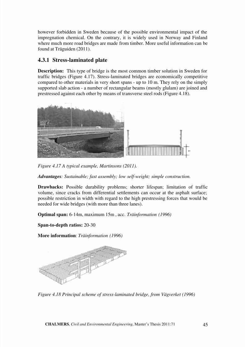
8/2/2019 Guidelines for Conceptual Design Short Span Bridges
http://slidepdf.com/reader/full/guidelines-for-conceptual-design-short-span-bridges 57/131
CHALMERS, Civil and Environmental Engineering, Master’s Thesis 2011:71 45
however forbidden in Sweden because of the possible environmental impact of theimpregnation chemical. On the contrary, it is widely used in Norway and Finlandwhere much more road bridges are made from timber. More useful information can befound at Träguiden (2011).
4.3.1 Stress-laminated plate
Description: This type of bridge is the most common timber solution in Sweden fortraffic bridges (Figure 4.17). Stress-laminated bridges are economically competitivecompared to other materials in very short spans - up to 10 m. They rely on the simplysupported slab action - a number of rectangular beams (mostly glulam) are joined andprestressed against each other by means of transverse steel rods (Figure 4.18).
Figure 4.17 A typical example, Martinsons (2011).
Advantages: Sustainable; fast assembly; low self-weight; simple construction.
Drawbacks: Possible durability problems; shorter lifespan; limitation of trafficvolume, since cracks from differential settlements can occur at the asphalt surface;possible restriction in width with regard to the high prestressing forces that would beneeded for wide bridges (with more than three lanes).
Optimal span: 6-14m, maximum 15m , acc. Träinformation (1996)
Span-to-depth ratios: 20-30
More information: Träinformation (1996)
Figure 4.18 Principal scheme of stress-laminated bridge, from Vägverket (1996)

8/2/2019 Guidelines for Conceptual Design Short Span Bridges
http://slidepdf.com/reader/full/guidelines-for-conceptual-design-short-span-bridges 58/131
46 CHALMERS, Civil and Environmental Engineering, Master’s Thesis 2011:71
4.3.2 Beam with timber deck
Figure 4.19 Cross-section of Skeppsvik bridge, from Träguiden (2011)
Description: This bridge type represents a solution for longer spans and mostly forpedestrian purposes. However, it is also used for road traffic, although not very oftenand with a lifespan of 40 years (Figure 4.19).
Advantages: Sustainable and aesthetically neutral; fast assembly; low self-weight.
Drawbacks: It needs good detailing; higher construction height; need for bracing;probably more expensive than concrete alternatives.
Optimal span: up to 15m for road traffic (needs more research).
Span-to-depth ratios: 15-20.
More information: Träguiden (2011), Martinsons (2011)
4.3.3 Beams with LVL1 deck
Figure 4.20 Cross-section of bridge with LVL deck, from Tosi (2010).
1 LVL – is an engineering product similar to plywood. It is a Laminated Veneer Lumber plate which isorthotropic and is made of lamels ( layers). KertoQ® and KertoD® are market products of FinnforestCorporation.
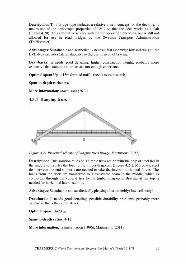
8/2/2019 Guidelines for Conceptual Design Short Span Bridges
http://slidepdf.com/reader/full/guidelines-for-conceptual-design-short-span-bridges 59/131
CHALMERS, Civil and Environmental Engineering, Master’s Thesis 2011:71 47
Description: This bridge type includes a relatively new concept for the decking. Itmakes use of the orthotropic properties of LVL, so that the deck works as a slab(Figure 4.20). This alternative is very suitable for pedestrian purposes, but is still notallowed for use in road bridges by the Swedish Transport Administration(Trafikverket).
Advantages: Sustainable and aesthetically neutral; fast assembly; low self-weight; theLVL deck provides lateral stability, so there is no need of bracing.
Drawbacks: It needs good detailing; higher construction height; probably moreexpensive than concrete alternatives; not enough experience.
Optimal span: Up to 15m for road traffic (needs more research).
Span-to-depth ratios: n.a.
More information: Martinsons (2011)
4.3.4 Hanging truss
Figure 4.21 Principal scheme of hanging truss bridge, Martinsons (2011)
Description: This solution relies on a simple truss action with the help of steel ties inthe middle to transfer the load to the timber diagonals (Figure 4.21). Moreover, steelties between the end supports are needed to take the internal horizontal forces. Theloads from the deck are transferred to a transverse beam in the middle, which isconnected through the vertical ties to the timber diagonals. Bracing at the top isneeded for horizontal lateral stability.
Advantages: Sustainable and aesthetically pleasing; fast assembly; low self-weight.
Drawbacks: It needs good detailing; possible durability problems; probably moreexpensive than other alternatives.
Optimal span: 16-23 m
Span-to-depth ratios: 4-12.
More information: Träinformation (1996), Martinsons (2011)

8/2/2019 Guidelines for Conceptual Design Short Span Bridges
http://slidepdf.com/reader/full/guidelines-for-conceptual-design-short-span-bridges 60/131
48 CHALMERS, Civil and Environmental Engineering, Master’s Thesis 2011:71
4.3.5 Lower arch
Figure 4.22 Timber arch bridge near Margretelun , Martinsons (2011)
Description: This structural type relies on glulam arches working mainly incompression. Only two road bridges of this type are built in Sweden (Figure 4.22).However, worldwide it is used more often for the purpose. The timber arch is verysuitable for pedestrian bridges with longer spans (up to 60 m). This solution is veryappropriate for valleys as the arch provides the logical leap over the gap.
Advantages: Sustainable and aesthetically very pleasing; fits the landscape; fast
assembly.
Drawbacks: It needs good detailing; possible durability problems; probably moreexpensive than other alternatives (like concrete); not suitable in clay due to highhorizontal forces that need to be accommodated.
Optimal span: 28-35m (in case of road traffic).
Span-to-depth ratios: n.a.
More information: Martinsons (2011)
4.4 Composite bridges
4.4.1 Steel I-girders and cast in-situ concrete deck
Description: In this bridge type most often two or more (depending on the width of bridge) I-girders (Figure 4.23) are fabricated and placed on the ready supports(abutments). After this, the steel girders are used to support the formwork needed tocast a concrete deck in-situ. Special attention is drawn to the connection between steeltop flange and the concrete deck, as it has to transfer longitudinal and transversalshear forces. The concrete deck usually has end walls like the bridge type described in
Section 4.1.4.

8/2/2019 Guidelines for Conceptual Design Short Span Bridges
http://slidepdf.com/reader/full/guidelines-for-conceptual-design-short-span-bridges 61/131
CHALMERS, Civil and Environmental Engineering, Master’s Thesis 2011:71 49
Figure 4.23 Composite bridge with steel I-girders and elevated foundations, fromVägverket (1996)
Advantages: This bridge type has a short construction time; is suitable for colderclimates as less man-hours are needed; ability to carry the deadweight of theformwork (Collin, 2006); possibility to lift the level of the foundation slab, i.e.avoiding working in water.
Drawbacks: higher initial cost of the materials compared to pure concrete solution.
Optimal span: > 20 m; 16-18 m for hot-rolled cross sections.
Span-to-depth ratios: 20-25 (single span); 30-35 (two spans).
More information: Collin (2006)
4.4.2 Steel I-girders and prefabricated concrete deck panels
Description: This bridge type is very similar to the one presented in Section 4.4.1, buthere the deck consists of prefabricated concrete elements instead of being cast in-situ.This solution is even more competitive in terms of time and optimisation, but raisessome additional technical difficulties. One of them is how to transfer the horizontalshear forces between steel top flange and the prefabricated concrete deck. Second ishow to transfer vertical shear forces between neighbouring elements (Figure 4.24).Another demand concerns high quality of fabrication, as tolerance requirements are
often very demanding. According to Collin (2006), the costs of prefabricated and castin-situ decks are almost the same; some contractors even stated that prefabricatedpanels are cheaper.
This concept is gaining popularity in Sweden and the Swedish TransportAdministration is satisfied with it. It is mostly used when time is a major factor and afast solution is needed.

8/2/2019 Guidelines for Conceptual Design Short Span Bridges
http://slidepdf.com/reader/full/guidelines-for-conceptual-design-short-span-bridges 62/131
50 CHALMERS, Civil and Environmental Engineering, Master’s Thesis 2011:71
Figure 4.24 Composite bridge with prefabricated deck elements, from Vägverket
(1996)
Advantages: Very short construction time; suitable for colder climates as less man-
hours are needed; increased quality; ability to carry the deadweight of the formwork (Collin, 2006).
Drawbacks: Higher demands on tolerances, very little allowance for late changes,little flexibility in design and shape.
Optimal span: > 20 m.
Span-to-depth ratios: 20-25 (single span); 30-35 (in case of two spans).
More information: Collin (2002)
4.4.3 Steel I-girders and FRP deck
Figure 4.25 Example of FRP deck panels (FiberSPAN™) panel placed on steel grid, from Composite Advantage (2011)
Description: This bridge type represents a very new trend in bridge engineering,where different types of polymers are used. It is mostly used for pedestrian bridges,
but more and more research is carried out in the field and concerning its applicationfor road bridges, especially in USA and UK. The fibres are mostly from glass, carbon

8/2/2019 Guidelines for Conceptual Design Short Span Bridges
http://slidepdf.com/reader/full/guidelines-for-conceptual-design-short-span-bridges 63/131
CHALMERS, Civil and Environmental Engineering, Master’s Thesis 2011:71 51
or aramid. FRP decks are still very costly solutions, but are gaining popularitybecause of their advantages. FRP can be used for the deck only (see Figure 4.25) orfor bridge elements T-sections (see Figure 4.26) which provide both beams and deck functions.
Figure 4.26 Example of FRP bridge elements with T-section, SuperFiberSPAN™,
from Composite Advantage (2011)
Advantages: High resistance to corrosion and chemical agents; excellent strength-weight ratio; superior durability; very easy prefabrication and erection; can beskewed; ability to mould complex forms.
Drawbacks: High initial cost; potential for material degradation (UV, alkali etc.);creep and shrinkage; limited knowledge and experience.
Optimal span: 8-18m (according to the authors).
Span-to-depth ratios: n.a
More information: Composite Advantage (2011); National Composites Network (2011).

8/2/2019 Guidelines for Conceptual Design Short Span Bridges
http://slidepdf.com/reader/full/guidelines-for-conceptual-design-short-span-bridges 64/131
52 CHALMERS, Civil and Environmental Engineering, Master’s Thesis 2011:71
4.4.4 Timber girders and cast in-situ concrete deck
Figure 4.27 Example of composite bridge from Germany, property of Miebach Ingenieurburo (2011).
Description: This solution relies on composite action between a timber girder systemand a reinforced concrete deck (Figure 4.27). The connection is made by shearconnectors in order to transfer forces at the joint interface such that a composite’T’- section is achieved (Figure 4.28). With the introduction of Eurocodes thesesolutions are nowadays allowed in the Swedish practice.
Advantages: It utilises well the strengths of the two main materials; goodaesthetically; lower deadweight; the concrete deck gives good protection of the timbergirders.
Drawbacks: Little knowledge; special attention to the connectors.
Optimal span: 8-15m (according to the authors).
Span-to-depth ratios: n.a
Figure 4.28 Cross sections

8/2/2019 Guidelines for Conceptual Design Short Span Bridges
http://slidepdf.com/reader/full/guidelines-for-conceptual-design-short-span-bridges 65/131
CHALMERS, Civil and Environmental Engineering, Master’s Thesis 2011:71 53
4.4.5 ’Folded plate system’
Figure 4.29 Folded plate concept, taken from Highway Bridge Services (2011)
Description: This bridge type is a new system developed by the University of Nebraska - Lincoln, USA. The system utilises composite action between – steelgirders folded in a factory and a concrete deck cast at the site or in the factory (Figure4.29). It is very suitable for short spans for secondary roads. As the bridge’s cross-section is almost a closed box (Figure 4.30), it has good torsional stiffness and lateralstability, i.e. very easy to mount and erect.
Advantages: Very rapid manufacturing and delivery; stability and safety during
construction; no need for bracing and stabilisers; easy inspection compared totraditional closed box girders.
Drawbacks: Innovative - research is still ongoing; not a flexible solution.
Optimal span: up to 20 m. (Restricted by manufacturing equipment).
Span-to-depth ratios: n.a.
More info: Highway Bridge Services (2011)
Figure 4.30 Cross section

8/2/2019 Guidelines for Conceptual Design Short Span Bridges
http://slidepdf.com/reader/full/guidelines-for-conceptual-design-short-span-bridges 66/131
54 CHALMERS, Civil and Environmental Engineering, Master’s Thesis 2011:71
4.5 Summary
The solutions presented in this chapter are the most common and suitable for short-span bridges for road and railway traffic. Along with the standard bridges, such as theconcrete slab-frame, some solutions according to new trends are introduced giving the
engineer a broader perspective and empowering his or her creativity. The list of solutions can always be updated and new solutions can be included. The propertieswritten under ’advantages’ and ’drawbacks’ are however often subjective and not allof them rely on scientific evidence. This is stated by Lövqvist (1994) where he pointsout that the most difficult part in creating a knowledge-based system for conceptualdesign is to acquire generally accepted conclusion of what is possible and in, whichsituation.

8/2/2019 Guidelines for Conceptual Design Short Span Bridges
http://slidepdf.com/reader/full/guidelines-for-conceptual-design-short-span-bridges 67/131
CHALMERS, Civil and Environmental Engineering, Master’s Thesis 2011:71 55
5 ‘Demand-solution’ guidelines for conceptualdesign
5.1 Approach and limitations
The output of the proposed procedure for conceptual design of short-span bridgespoints out, which concepts or structural systems are the most suitable for a givendesign case. The promising solutions are chosen from a fixed number of the mostcommon bridge types for short-span bridges for road or railway traffic. The step-by-step approach is divided in four distinct levels with sublevels. All of these aredescribed in detail in the following sections. The methodology of creating theguidelines was a constant iterative process with continuous evaluation. Feedback wasreceived focusing on practicality and applications in current conceptual designpractice. Two case studies were carried out, see Chapter 6, to further calibrate and
improve the proposed guidelines.
Figure 5.1 ‘Demand-solution’ step-by-step methodology scheme
The proposed structure of the methodology is seen in Figure 5.1. The solution spaceon the right shows that the number of appropriate solutions is reduced as the user goesthrough the design process. A toolbox supporting the methodology was developed onthe base of Microsoft Excel and made semi-automated to simplify the work of theuser and increase his or her speed. Moreover, it is structured in a way such that theprocedure is transparent and easy to follow.

8/2/2019 Guidelines for Conceptual Design Short Span Bridges
http://slidepdf.com/reader/full/guidelines-for-conceptual-design-short-span-bridges 68/131
56 CHALMERS, Civil and Environmental Engineering, Master’s Thesis 2011:71
The first step is concerning mostly the input, while the last step is more output (result)oriented. All the steps and stages of the methodology and the developed Excel toolboxcan be seen in detail in Appendix A.
The guidelines were developed with some important points in mind:
Versatility – the proposed toolbox covers as many different design situationsas possible. It can be used for ’General’ or ’Total’ contract with the onlydifference concerning ‘demand prioritising’ (see Section 5.2.3).
Flexibility – the whole guideline has an open structure and was developed in away such that it can be further developed and even expanded (longer spans;pedestrian bridges). It allows for further improvement such as adding newsolutions, changing the contents and fixed parameters. The focus of theauthors was on the methodology, not on the precision of the content itself as itcan be easily improved with further work.
Balance – although some decisions and exclusions are made by the toolboxwithout the user’s approval, the designer still has control and freedom over thefinal solution. Neither is the guideline too vague, nor it takes final decisionswithout using the engineer’s expertise.
Visualisation and dialogue – the created toolbox can be used as a tool topresent to the client a structured way of work and even extract his or her inputsimultaneously. The speed of the toolbox provides good options to makechanges on the spot and propose different solutions during the meetings.
The limitations of the toolbox are as follows:
The maximum allowed input length is 30 (32) meters.
This version of the toolbox with supporting guidelines disregards pedestrianbridges, although the possibility to include pedestrian and bicycle lanes isconsidered for road or railway bridges.
Only road and railway bridges are covered by the guidelines.
Up to five predefined solutions (promising alternatives) can be compared at
the same time, plus two additional solutions added by the user manually.
5.2 General description and aim
This step comprises of set of questions (questionnaire) that helps to define the actualdesign situation as much as possible. Referred to as the main menu as well, this partstores decisions and project information more consistently. Each question is explainedby a description, alternative answers and which solutions that are excluded for acertain answer. For each question one answer must be selected. The two mainpurposes of the input questionnaire are: definition of design case and documentationof the conceptual design process and situation. Most of the exclusions are based onthe knowledge the authors from practising engineers. This was achieved by analysingquestionnaires sent to engineers and by interviews. After detailed interviews and
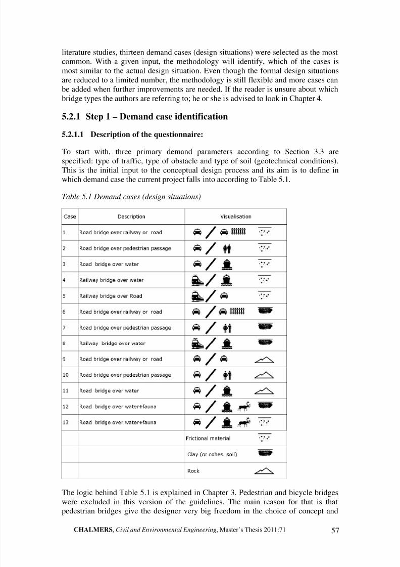
8/2/2019 Guidelines for Conceptual Design Short Span Bridges
http://slidepdf.com/reader/full/guidelines-for-conceptual-design-short-span-bridges 69/131
CHALMERS, Civil and Environmental Engineering, Master’s Thesis 2011:71 57
literature studies, thirteen demand cases (design situations) were selected as the mostcommon. With a given input, the methodology will identify, which of the cases ismost similar to the actual design situation. Even though the formal design situationsare reduced to a limited number, the methodology is still flexible and more cases canbe added when further improvements are needed. If the reader is unsure about which
bridge types the authors are referring to; he or she is advised to look in Chapter 4.
5.2.1 Step 1 – Demand case identification
5.2.1.1 Description of the questionnaire:
To start with, three primary demand parameters according to Section 3.3 arespecified: type of traffic, type of obstacle and type of soil (geotechnical conditions).This is the initial input to the conceptual design process and its aim is to define inwhich demand case the current project falls into according to Table 5.1.
Table 5.1 Demand cases (design situations)
The logic behind Table 5.1 is explained in Chapter 3. Pedestrian and bicycle bridgeswere excluded in this version of the guidelines. The main reason for that is thatpedestrian bridges give the designer very big freedom in the choice of concept and

8/2/2019 Guidelines for Conceptual Design Short Span Bridges
http://slidepdf.com/reader/full/guidelines-for-conceptual-design-short-span-bridges 70/131
58 CHALMERS, Civil and Environmental Engineering, Master’s Thesis 2011:71
solution. This makes it very difficult to categorise the most bridge types. Moreover,trying to industrialise and classify pedestrian bridges seems to restrict and discouragethe designer instead of fuelling his creativity. Pedestrian bridges have much biggeraesthetical demands and possibilities and this is there where engineers and architectspush the limits of technology and art. Another reason for excluding pedestrian bridges
was the need to fit in the timeline of the thesis project. Although including pedestrianbridges can be possible, it requires more time for research to describe and classify thevast variety of these structures.
If a given design situation cannot be classified precisely by one of the 13 options or isa combination between them (for example the obstacle is both water and a pedestrianpass), the user is advised to focus on the main characteristics or decisive points. Forexample, the road traffic load will be the governing factor for the solution, eventhough the bridge will have a pedestrian walkway as well. If two standardised demandcases are very close, the user is advised to make the whole procedure twice and thenassess the results. Finally, it is unlikely that a certain bridge project will fall outside all
of the standardised cases unless it is longer than 30 m (outside the scope of the thesiswork) or it is a quite unique and special case where generalising will not beadvantageous.
The three primary questions are as follows:
1. What type of traffic is the bridge designed for?
Road traffic and/or fauna – see Section 3.3 for explanations
Railway – it is not differentiated for what type of speed; if high speed rail is
the case, special analysis is needed.
Exclusion of bridge types:
In case of a railway bridge all timber solutions (Section 4.3) are excluded asoptions. All composite bridges (Section 4.4) except steel girders with in-situconcrete deck are disregarded since knowledge about their performance forrailway loads seems to be limited.
2. What type of obstacle does the bridge need to cross?
If a combination of obstacles is present, the user must select the dominating one that
causes the highest demands and requirements).
Water – can be a creek, stream, channel or a small river.
Road and/or railway – at this stage no differentiation is made between roadand railway as they put similar demands and the only difference is the neededclearance height.
Pedestrian and bicycle passage – observe that a pedestrian passage means apedestrian path under a road or railway not above.
Fauna passage (and water) – a natural path for animals, which has to bepreserved. Very often it is accompanied by a water source (stream, river).
8/2/2019 Guidelines for Conceptual Design Short Span Bridges
http://slidepdf.com/reader/full/guidelines-for-conceptual-design-short-span-bridges 71/131
CHALMERS, Civil and Environmental Engineering, Master’s Thesis 2011:71 59
Exclusion of bridge types:
Corrugated steel arch (Section 4.2.1) is excluded when the obstacle is a roadand/or a railway.
Prefabricated concrete tunnel (Section 4.1.10) is generally used when theobstacle is a pedestrian or bicycle passage and all other alternatives areexcluded.
3. What is the predominant ground condition?
The predominant ground (soil) condition at the site is specified as:
Clay or cohesive soil.
Rock – if rock mass is present, the ground conditions are generally consideredto be very good.
Frictional material – can be sandy soil, moraine or other type of cohesion lesssoil.
If it is obvious that there is a thin layer of poorer soil, which can be easily removed,then the soil beneath should be considered for the main condition.
Exclusion of bridge types:
In case of clay or cohesive soil, prefabricated concrete solutions such asprecast hollow core elements, precast beams and precast tunnels are excluded
due to possible problems with differential settlements and reduced robustnessof these solutions. Moreover, the timber arch (with the traffic above it) isdisregarded, as it is very difficult to resist high horizontal arch forces incohesive soil.
In case of rock, solutions with integral abutments are removed as they alwaysrely on piling.
After answering these three primary questions, a result like the one exemplified inTable 5.2 will be obtained. At the same time some of the bridge types have beenexcluded and a certain number remains accordingly, see Table 5.4. The numbering of
the solutions is according to Figure 5.4.

8/2/2019 Guidelines for Conceptual Design Short Span Bridges
http://slidepdf.com/reader/full/guidelines-for-conceptual-design-short-span-bridges 72/131
60 CHALMERS, Civil and Environmental Engineering, Master’s Thesis 2011:71
Table 5.2 Demand space – example of case identification
Case Description Visualisation Code Status
1 Road bridge over railway or road A1 B2 C3 FALSE
2 Road bridge over pedestrian passage A1 B3 C3 FALSE
3 Road bridge over water A1 B1 C3 ok
4 Railway bridge over water A3 B1 C3 FALSE
5 Railway bridge over road A3 B2 C3 FALSE
6 Road bridge over railway or road A1 B2 C1 FALSE
7 Road bridge over pedestrian passage A1 B3 C1 FALSE
8 Railway bridge over water A3 B1 C1 FALSE
9 Road bridge over railway or road A1 B2 C2 FALSE
10 Road bridge over pedestrian passage A1 B3 C2 FALSE
11 Road bridge over water A1 B1 C2 FALSE
12 Road bridge over water+fauna A1 B4 C2 FALSE
13 Road bridge over water+fauna A1 B4 C1 FALSE
Demand space
After completing the demand case identification, the user should continue answeringthe questions of the questionnaire. Hereafter, they are described thoroughly.
4. What is the expected (provisional) length of the bridge?
Here the user has to input the preliminary length of the bridge (see Figure 5.2 fordefinitions) in the range from 2 to 32 meters. Even though the scope of the thesisproject is short-span bridges with a length less than 30 meters, a margin is provided.The tolerance given is ±1m, as it is very difficult to specify an exact length at thisearly stage. Important to point out is that the bridge can have two or more spans but
the total length should be less or equal to 32 meters. Even though the length can be apart of the solution and somehow restricts the designer in the following steps, thisinput is important in order to further reduce the amount of solutions, possible and/orappropriate. It is very common that the designer has freedom to change the level of the road (for new roads or railways), thus varying the needed length of the bridge (seeFigure 5.2). In such case the user is advised to use the methodology twice with bothoptions. Later change of the bridge length is always possible. Hence, an importantaspect is whether the bridge length is fixed or can be chosen within an interval. This iswhy the span ranges must be updated and verified continuously. Visualisation of proposed span ranges for different bridge types is presented in Table 5.3.
In the Excel toolbox the specified length for the actual design situation is compared tothe optimal and possible span range for each of the bridge types. This is done

8/2/2019 Guidelines for Conceptual Design Short Span Bridges
http://slidepdf.com/reader/full/guidelines-for-conceptual-design-short-span-bridges 73/131
CHALMERS, Civil and Environmental Engineering, Master’s Thesis 2011:71 61
automatically, but the designer is always advised to double-check and asses, if theproposed reduction of possible bridge types is reasonable.
Figure 5.2 Length of bridge compared to elevation of road (vertical profile)
By specifying the length in the toolbox, bridge types that fall out of the possibleintervals will be disregarded. This exclusion is mostly based on cost and tradition
considerations. Three status levels exist (Table 5.3):
‘OK’ – The length is considered optimal for the bridge type.
‘OK?’ – The bridge type is satisfactory for the given length, but probably notvery optimal. The designer manually decides whether to disregard the bridgetype or not.
‘Outside’ – The bridge type is considered inappropriate for the given length.In the column ‘prestressing’ it is advised to use prestressing if ‘P’ is shown. If ‘P+’ isshown, prestressing is considered to be necessary.
Exclusion of bridge types: Bridge types not appropriate for the specified length areexcluded. An example of output from the toolbox is shown in Table 5.3.

8/2/2019 Guidelines for Conceptual Design Short Span Bridges
http://slidepdf.com/reader/full/guidelines-for-conceptual-design-short-span-bridges 74/131
62 CHALMERS, Civil and Environmental Engineering, Master’s Thesis 2011:71
Table 5.3 An example of length exclusion
№
R O A D T R A F F I C
S t a t u s
P r e s t r .
L e n g t h
2
3
4
5
6
7
8
9
1 0
1 1
1 2
1 3
1 4
1 5
1 6
1 7
1 8
1 9
2 0
2 1
2 2
2 3
2 4
2 5
2 6
2 7
2 8
2 9
3 0
3 1
3 2
3 3
3 4
3 5
№
S o l u t i o n :
[ m ]
1
S l
a b - f r a m e i n - s i t u
O K
O K
1 2
1
2
B e
a m - f r a m e i n - s i t u
O u t s i d e
O K
1 2
2
3
I n
t e g r a l a b u t m e n t s
O K ?
1 2
3
4
S i
m p l y s u p p o r t e d s l a b i n - s i t u
O K
O K
1 2
4
5
S i
m p l y s u p p o r t e d b e a m i n
- s i t u
O u t s i d e
1 2
5
6
P r
e f a b .
h o l l o w c o r e
O u t s i d e
1 2
6
7
P r
e f a b . p r e - t e n s i o n e d b e a m s
O K ?
1 2
7
8
P r
e f a b . p e d e s t r i a n t u n n e l
O u t s i d e
1 2
8
9
C o
r r u g a t e d s t e e l a r c h
O u t s i d e
1 2
9
1 0 S t
r e s s - l a m i n a t e d p l a t e
O K
1 2
1 0
1 1 B e
a m b
r i d g e w i t h t i m b e r d e c k
O K
1 2
1 1
1 2 B e
a m b
r i d g e w i t h L V L d e c k
O K
1 2
1 2
1 3 H a n g i n g t r u s s t i m b e r b r i d g e
O u t s i d e
1 2
1 3
1 4 T i m b e r a r c h b r i d g e
O u t s i d e
1 2
1 4
1 5 S t
e e l I - g i r d e r s a n d i n - s i t u R C d e c k
O u t s i d e
1 2
1 5
1 6 S t
e e l I - g i r d e r s a n d p r e f a b .
d e c k
O u t s i d e
1 2
1 6
1 7 S t
e e l I - g i r d e r s a n d F R P d e c k
O K
1 2
1 7
1 8 T i m b e r g i r d e r s a n d i n - s i t u R C d e c k
O K
1 2
1 8
1 9 " F
o l d e d p l a t e s y s t e m "
O K
1 2
1 9
B a
c k t o m a i n m e n u
O K
o p t i m a l
O K ?
s a t i s f y i n g ( s o l u t i o n i s n o t
v e r y o p t i m a l )
" O u t s i d e "
n o t s a t i s f y i n g ( n o t a p p r o p
r i a t e )
P
p r e s t r e s s i n g a d v i s e d
P +
p r e s t r e s s i n g n e e d e d
№
R A I L W A Y T R A F F I C
S t a t u s
P r e s t r .
L e n g t h
2
3
4
5
6
7
8
9
1 0
1 1
1 2
1 3
1 4
1 5
1 6
1 7
1 8
1 9
2 0
2 1
2 2
2 3
2 4
2 5
2 6
2 7
2 8
2 9
3 0
3 1
3 2
3 3
3 4
3 5
№
S o l u t i o n :
[ m ]
1
S l
a b - f r a m e i n - s i t u
O K
O K
1 2
1
2
B e
a m - f r a m e i n - s i t u
O K ?
1 2
2
4
S i
m p l y s u p p o r t e d s l a b i n - s i t u
O K
O K
1 2
4
5
S i
m p l y s u p p o r t e d b e a m i n
- s i t u
O u t s i d e
1 2
5
9
C o
r r u g a t e d s t e e l a r c h
O u t s i d e
1 2
9
1 5 S t
e e l I - g i r d e r s a n d i n - s i t u R C d e c k
O u t s i d e
1 2
1 5
2 0 T h
r o u g h c o n c r e t e b e a m i n
- s i t u ,
f l a t
O K
O K
1 2
2 0
2 1 T h
r o u g h c o n c r e t e b e a m i n
- s i t u , r i b b e d
O K
O K
1 2
2 1
S p a n
l e n g t h
r a n g e s
f o r d i f f e r e n t s o l u t i o n s
H i n t : M a r k t h e c o l u m n r e p r e s e n t i n g
y o u r i n p u t s p a n f o r e a s i e r v i s u a l i s a t i o n .

8/2/2019 Guidelines for Conceptual Design Short Span Bridges
http://slidepdf.com/reader/full/guidelines-for-conceptual-design-short-span-bridges 75/131
CHALMERS, Civil and Environmental Engineering, Master’s Thesis 2011:71 63
5. Can construction work be carried out in the obstacle area?
This questions concerns the local site conditions - difficult geometry or inability towork in the obstacle area (see Figure 5.3 for definitions). The purpose is to assess theavailability of space for formworks, construction works and other technological
procedures and limitations.
Figure 5.3 Definition of obstacle area
Yes – there are no problems to work in the obstacle area (see Figure 5.3). Theobstacle can be one of the mentioned in Question 2. If a water obstacle ispresent, it is a permitted to work in water. If small restrictions exist, they arenot severe and can easily be managed with little resources (time, money,machinery, stop of traffic).
Yes, but with some restrictions or difficulties – work is restricted by either
geometrical limitations or environmental restrictions (work in water forexample). Traffic cannot be stopped, but can be restricted with reducedcapacity (speed). For instance, a middle support can be constructed whiletraffic is running.
No – no work can be done in the obstacle's area neither around it (exceptabutments).
Exclusion of bridge types:
If ‘Yes, but with some restrictions or difficulties’, all cast in-situ solutions are
proposed for exclusion. It is assumed that temporary formwork can beprovided but with a sufficient span without affecting the space beneath thenew bridge (obstacle area). It is assumed that the slab-frame bridge can be castbeside and launched into its final position, if this possibility exists.
If ‘No’ and railway traffic in the obstacle is present, all cast in-situ framesolutions are removed, because of their need for extensive formwork. Variousbuilding techniques and ways of transportation to the site exist for simplysupported slabs and beams for railway solutions (see Sections 4.1.4, 4.1.5,4.1.7 and 4.1.8) (Banverket, 2007). For road traffic all cast in-situ options areremoved.
6. Is construction time of major concern (crucial importance)?

8/2/2019 Guidelines for Conceptual Design Short Span Bridges
http://slidepdf.com/reader/full/guidelines-for-conceptual-design-short-span-bridges 76/131
64 CHALMERS, Civil and Environmental Engineering, Master’s Thesis 2011:71
Has the client stressed time to be of main concern or is it understandable as default forthe actual project? Is there an urgent need for a bridge or would the bridgeconstruction cause complete traffic stop, reduce its capacity or disturb otherprocesses? Would the bridge construction cause big changes in logistics and/orfinancial losses? Depending on the actual situation one of the following two
alternative answers is selected:
Yes
No
Exclusion of bridge types:
In case of ‘Yes’, all cast in-situ solutions except the slab-frame aredisregarded. It is assumed that these are the most time consuming and wouldnot be suitable if the client demands fast construction. The slab-frame option
can be cast besides and launched to its position (if ‘Yes’ to Q5), thus keepingthe existing road/railway operate as much as possible.
7. Is this a new road/railway for the traffic (no bridge already exists)?
Is the project aimed for a completely new road or railway? If a road/rail exists andtraffic is running and operation cannot stop, then it is a replacement of a bridge (or itsdeck). In this case choose 'No'. It is important to remember that the question concernsthe traffic and not the obstacle.
Yes
No
Exclusion of bridge types:
In case of a bridge replacement (‘No’) and inability to work in the obstaclearea (‘No’ to Q5), corrugated steel arch is removed due to the nature of itsconstruction process.
8. Is there a possibility to place a middle support in the obstacle area?
This question clarifies whether a support can be placed or not. For instance, can a
middle support be placed in water or in the middle of a two-lane road?
Yes
No
Recommendation for Exclusion of bridge types:
If ‘Yes’ and the input span is above 20 m, the designer is advised to consider acontinuous bridge, but probably with not more than 2 spans considering thetotal length limit of 30 meters.

8/2/2019 Guidelines for Conceptual Design Short Span Bridges
http://slidepdf.com/reader/full/guidelines-for-conceptual-design-short-span-bridges 77/131
CHALMERS, Civil and Environmental Engineering, Master’s Thesis 2011:71 65
9. What is the needed bridge shape (in the horizontal plane)?
If there is a requirement from the landscape architect or the client for layout of thebridge (Figure 5.4), it is taken into account here. In addition, the designer can alsomake a decision with regard to local geometrical conditions.
Figure 5.4 Various horizontal layouts
This question is answered by one of the following alternatives:
Straight – the centreline of the bridge is perpendicular to its abutments.
Skewed (at a skew angle) – the bridge’s centreline is at an angle different from90 deg to its abutments.
Curved – the bridge has to follow a horizontal curve.
Exclusion of bridge types:
If ‘Skewed’ is chosen, prefabricated concrete solutions (see Section 4.1) areremoved, because of possible problems with differential settlements, transferof torsional moments and restrictions with regard to the production process.Moreover, hanging timber truss (Section 4.3.4) and arch bridges (Section4.3.5) are excluded, since asymmetry causes complications for calculation andproduction of timber bridges of these types.
If ‘Curved’, all prefabricated concrete solutions (Section 4.1.8, 4.1.9 and
4.1.10), timber solutions (Section 4.3), composite (Section 4.4) (except withsteel and concrete (numbers 15 and 16)) and corrugated steel arch areremoved. This is mainly because of technical or production issues.
10. What is the needed position in the vertical plane?
If there is a specific requirement from the landscape architect or the client concerningthe vertical layout, the designer should choose one of the following options (Figure5.5). Here it is important to identify a need for a distinguished vertical curve.
Horizontal or inclined
In a vertical curve

8/2/2019 Guidelines for Conceptual Design Short Span Bridges
http://slidepdf.com/reader/full/guidelines-for-conceptual-design-short-span-bridges 78/131
66 CHALMERS, Civil and Environmental Engineering, Master’s Thesis 2011:71
Figure 5.5 Various vertical layouts
Exclusion of bridge types:
If ‘In a vertical curve’ is selected, prefabricated concrete solutions (precasthollow core, precast beams), stress-laminated timber bridge and ‘folded plate’system are removed due to technology and production issues.
11. Other special requirements.
Here the user is asked to write down any other requirements or demands specific forthe actual project. Some special circumstances or conditions should be described aswell. Documentation is vital for knowledge storage and developed design proceduresin the future. For example, after having used this methodology for a number of bridges, the designers can track a trend in their decisions and probably implement it
back into the toolbox as definitive advices.
12. Where is the bridge situated?
Urban area – city centre or very populated area.
Highway area (suburban) – around a highway region or in the outskirts of acity; industrial area with few inhabitants.
Countryside – a bridge outside living areas, mostly on intercity roads orrailways.
Recommendation for Exclusion of bridge types:
If the bridge is located in an urban area, timber bridges might be difficult to fitinto the built environment.
13. What is the needed width of the bridge or how many lanes/lines areneeded?
Single lane/line
(2-3) lanes/lines

8/2/2019 Guidelines for Conceptual Design Short Span Bridges
http://slidepdf.com/reader/full/guidelines-for-conceptual-design-short-span-bridges 79/131
CHALMERS, Civil and Environmental Engineering, Master’s Thesis 2011:71 67
4 lanes/lines or more
Exclusion of bridge types:
If the bridge needs to be accommodate four lanes/lines or more (i.e. highway)
with continuous width (not separated in two parallel parts), all timber solutionsare excluded. Since timber bridges are more suitable for smaller roads (lowerload, traffic and other effects), it is probably not economically effective todesign them for highway use.
5.2.2 Step 2 - Reducing solution space
This step is carried out be the means of the toolbox and accomplishes exclusions of bridge types following the input from Step 1. This step forms the link between themost common design cases and the most common bridge types and is considered asthe most difficult and complicated part of the ‘demand-solution’ methodology. The
reason for this is the difficulty to give definitive answers to questions like what isappropriate, impossible, and expensive and so on. Often the answers to these aresubjective and vary very much from case to case and from person to person. However,the design approach with its guidelines helps the engineer to get a good overview andpreparedness to take better decisions.
Three main reductions of the initial solution space are carried out during the process:
Exclusions after identifying demand case (Table 5.4).
Automatic exclusion after filling out the input questionnaire (Table 5.5).
Final subjective exclusion by the designer.

8/2/2019 Guidelines for Conceptual Design Short Span Bridges
http://slidepdf.com/reader/full/guidelines-for-conceptual-design-short-span-bridges 80/131
68 CHALMERS, Civil and Environmental Engineering, Master’s Thesis 2011:71
Table 5.4 Demand cases with their respective parts of the total solution spaces
C a s e
D e s c r i p t i o n
V i s u a l i s a t i o n
1
R o a d b r i d g e o v e r r a i l w
a y o r r o a d
1
2
3
4
5
6 7
1 0
1 1
1 2
1 3
1 4
1 5
1 6
1 7 1
8
1 9
2
R o a d b r i d g e o v e r p e d e
s t r i a n p a s s a g e
1
2
3
4
5
6 7
8
9
1 0
1 1
1 2
1 3
1 4
1 5
1 6
1 7 1
8
1 9
3
R o a d
b r i d g e o v e r w a t e r
1
2
3
4
5
6 7
9
1 0
1 1
1 2
1 3
1 4
1 5
1 6
1 7 1
8
1 9
4
R a i l w a y b r i d g e o v e r w a t e r
1
2
3
4
5
9
1 5
2 0
2 1
5
R a i l w a y b r i d g e o v e r R o a d
1
2
3
4
5
1 5
2 0
2 1
6
R o a d b r i d g e o v e r r a i l w
a y o r r o a d
1
2
3
4
5
1 0
1 1
1 2
1 3
1 5
1 6
1 7 1
8
1 9
7
R o a d b r i d g e o v e r p e d e
s t r i a n p a s s a g e
1
2
3
4
5
9
1 0
1 1
1 2
1 3
1 5
1 6
1 7 1
8
1 9
8
R a i l w a y
b r i d g e o v e r w
a t e r
1
2
3
4
5
9
1 5
2 0
2 1
9
R o a d b r i d g e o v e r r a i l w
a y o r r o a d
1
2
4
5
6 7
1 0
1 1
1 2
1 3
1 4
1 5
1 6
1 7 1
8
1 9
1 0
R o a d b r i d g e o v e r p e d e
s t r i a n p a s s a g e
1
2
4
5
6 7
8
9
1 0
1 1
1 2
1 3
1 4
1 5
1 6
1 7 1
8
1 9
1 1
R o a d
b r i d g e o v e r w a t
e r
1
2
4
5
6 7
9
1 0
1 1
1 2
1 3
1 4
1 5
1 6
1 7 1
8
1 9
1 2
R o a d
b r i d g e o v e r w a t
e r + f a u n a
1
2
3
4
5
9
1 0
1 1
1 2
1 3
1 5
1 6
1 7 1
8
1 9
1 3
R o a d
b r i d g e o v e r w a t
e r + f a u n a
1
2
3
4
5
6 7
9
1 0
1 1
1 2
1 3
1 4
1 5
1 6
1 7 1
8
1 9
S o l u t i o n
s p a c e

8/2/2019 Guidelines for Conceptual Design Short Span Bridges
http://slidepdf.com/reader/full/guidelines-for-conceptual-design-short-span-bridges 81/131
CHALMERS, Civil and Environmental Engineering, Master’s Thesis 2011:71 69
Table 5.5 Excluded bridge types depending on various demand parameters
I n q u e s t i o
n :
1
3
5
6
9
9
1 0
1 2
1 3
1
S l a
b f r a m e i n - s i t u
2
B e a m - f r a m e i n - s i t u
3
I n t
e g r a l a b u t m e n t s
4
S i m
p l y s u p p o r t e d s l a b i n - s i t u
f o r r o a d
5
S i m
p l y s u p p o r t e d b e a m i n
- s i t u
f o r r o a d
6
P r e
f a b .
h o l l o w c o r e
7
P r e
f a b . p r e - t e n s i o n e d b e a m s
8
P r e
f a b . p e d e s t r i a n t u n n e l
9
S t e e l
C o r r u g a t e d s t e e l a r c h
1 0
S t r
e s s - l a m i n a t e d p l a t e
?
1 1
B e a m b
r i d g e w i t h t i m b e r d e c k
?
?
1 2
B e a m b
r i d g e w i t h L V L d e c k
?
?
1 3
H a n g i n g t r u s s t i m b e r b r i d g e
?
?
1 4
T i m
b e r a r c h b r i d g e
?
?
I f
n o
c o n s t r u c t i o n
w o r k
i n
o b s t a c l e ' s
a r e a ?
I f l i m i t e d
t i m e
f o r
c o n s t r u c t
i o n ?
I f
l o c a t e d
i n
u r b a n
a r e a ?
I f
w i d t h
≥
4
l a n e s / l i n e s
?
I f
s k e w e d ?
I f
c u r v e d
h o r i z o n t a l l y ?
I f
c u r v e d
v e r t i c a l l y ?
C o n c r e t e T i m b e r
C o m p o s i t e
I f c l a y
E x c l u s i o n t a b l e
I f
r a i l w a y
b r i d g e
1 5
S t e
e l I - g i r d e r s a n d i n - s i t u R C d e c k
1 6
S t e
e l I - g i r d e r s a n d p r e f a b .
d e c k
1 7
S t e
e l I - g i r d e r s a n d F R P d e c k
?
1 8
T i m
b e r g i r d e r s a n d i n - s i t u R C d e c k
?
?
1 9
" F o
l d e d p l a t e s y s t e m "
2 0
T h r o u g h b e a m i n
- s i t u ,
f l a t
2 1
T h r o u g h b e a m i n
- s i t u , r i b b e d
e x c l u d e d
?
p r o p o s e d f o r e x c l u s i o n
C o m p o s i t e
C o n c r e t e
( r a i l w a y o n l y )

8/2/2019 Guidelines for Conceptual Design Short Span Bridges
http://slidepdf.com/reader/full/guidelines-for-conceptual-design-short-span-bridges 82/131
70 CHALMERS, Civil and Environmental Engineering, Master’s Thesis 2011:71
After completing Step 1, meaning identifying the actual demand case and answeringall the questions concerning the design situation, the designer can start to analyse thesolution space. A typical example is shown in Figure 5.6. Each number represents asolution and the ones marked in grey have been proposed for exclusion. The crossed
out number are the excluded alternatives. In this case, only solutions 1, 8 and 9 areconsidered appropriate for the given input and number 10 is up to the designer.
1 2 3 4 5 6 7 10 11 12 13 14 15 16 17 18 19
1 2 3 4 5 6 7 8 9 10 11 12 13 14 15 16 17 18 19
1 2 3 4 5 6 7 9 10 11 12 13 14 15 16 17 18 19
1 2 3 4 5 9 15 20 21
1 2 3 4 5 15 20 21
1 2 3 4 5 10 11 12 13 15 16 17 18 19
1 2 3 4 5 9 10 11 12 13 15 16 17 18 19
1 2 3 4 5 9 15 20 21
1 2 4 5 6 7 10 11 12 13 14 15 16 17 18 19
1 2 4 5 6 7 8 9 10 11 12 13 14 15 16 17 18 19
1 2 4 5 6 7 9 10 11 12 13 14 15 16 17 18 19
1 2 3 4 5 9 10 11 12 13 15 16 17 18 19
1 2 3 4 5 6 7 9 10 11 12 13 14 15 16 17 18 19
Solu t ion space
Figure 5.6 An example of solution space before the final subjective exclusion
At this state the output is critically analysed. Remaining bridge types can still beexcluded and other can be added depending on the engineer's own experience. If thereis a bridge type left, which is rather impossible or inadequate, it should be removed.However, even if the designer knows that some of the remaining bridge types are notvery likely to be optimal, he or she is advised to keep them. The best choice is notalways straight forward and it is better to have a broader range of options in the finalstep. Moreover, the developed toolbox speeds the process so leaving more solutionsdoes not necessarily lead to proportional increase of spent time. After this step a
number of promising solutions remain for detailed comparison by means of a rankingmatrix.
The adopted approach is semi-automated. Even though some solutions areautomatically disregarded, the designer is still the last instance for selecting theconcept. This eliminates mistakes such as following’ the programme ‘blindly.
5.2.3 Step 3 - Demand prioritising
In Section 2.2 four different approaches for ‘key parameter identification’ werepresented. Considering the scope of this thesis project and desired results, the
‘objective tree’ was chosen as most suitable approach for comparison and evaluationof various demands. One reason is that it represents a logical system for giving

8/2/2019 Guidelines for Conceptual Design Short Span Bridges
http://slidepdf.com/reader/full/guidelines-for-conceptual-design-short-span-bridges 83/131
CHALMERS, Civil and Environmental Engineering, Master’s Thesis 2011:71 71
importance to different parameters. According to Dekker (2000) this method is themost analytical and consistent. It is also very suitable for the task, since at each pointthe designer and the client can discuss the importance of a certain demand parameter.As in the current practice in Sweden the importance of demand parameters isdiscussed via a series of meetings, the ‘objective tree’ can be constantly updated.
Another good point of this method is that it shows very clearly and systematically thechoices made. Moreover, it allows for two levels of ranking – quick and detailed. Thisis achieved by using different levels of demands (objectives). The ‘objective tree’provides a deeper understanding of the importance of each objective. This isadvantageous for keeping knowledge well archived, so that further on the logic andreasons behind decisions is clearly seen. The authors also recommend writing shortcomments under each grade in order to further clarify the task and decisions for futurereaders. After completing this part, each aspect of a bridge will have a ‘weighting’factor showing its importance qualitatively. A legend of the method is shown inFigure 5.7.
A1
30 7,2
Gives the
relative weight
(prior ity) of th is
demand to the
whole bridge.
Input a number
(0÷100).
Represents how
th is demand is in
relation to its
'mother'.
Legend:Input a number (0÷100)
Aesthetics
Figure 5.7 Legend of the objective tree
Six general demand areas are formulated in a way (Figure 5.8) that the client canunderstand them and give proper weights (values) to the so called ‘flexible’ demandparameters and sometimes even to the ‘fixed’ ones (from consulting engineer’s pointof view it is suitable for ‘Total contract’ where the contractor is the client andproduction is very important). The number of demand cases and their names werechosen after many iterations and discussions with the designers. ‘Fixed’ parametersare considered as basic and compulsory, while ‘flexible’ can be seen as ‘extras’,
which are optional but able to create additional values.

8/2/2019 Guidelines for Conceptual Design Short Span Bridges
http://slidepdf.com/reader/full/guidelines-for-conceptual-design-short-span-bridges 84/131
72 CHALMERS, Civil and Environmental Engineering, Master’s Thesis 2011:71
Demand
parameters
Flexible Fixed
Aesthetical
design
Service life
added valuesEnvironmental
issuesPerformance
Structural
designProduction
Figure 5.8 Demand tree
The separation into ‘fixed’ and ‘flexible’ areas was made as an attempt to adapt theprioritising of objectives to the needs of the designer and his or her goal to extract thedemands of the client better. By giving values to the ‘flexible’ parameters, the clientcan stress whether and how much he or she is willing to pay for added values in termsof importance. This is done by spreading 100 points between parameters at the samelevel (Figure 5.9). If the client or the designer cannot decide upon preferences orneeds, he or she should distribute the points evenly. In this way the overall result willnot be affected, but still the parameters will be considered. Moreover, this approach isan approximation and the values are estimated roughly, thus very much thought is not
needed in this early stage of design.
33 16,5
A est h et ica l d esi gn Se rv ice l if e a dd ed v alu es En vi ro nm e nt al issu es
33 16,5 34 17
Flex ib l e parameter s
Added values or stress on
parameters
50 50
Figure 5.9 Weighting of flexible parameters
Per f o r m an ce St r u ct u r a l d esign Pr odu ct ion
33 16,5 33 16,5 34 17
Fixed paramete r s
Basic values
50 50
Figure 5.10 Weighting of fixed parameters
Fixed parameters (Figure 5.10) are the basic demands that each solution shouldsatisfy. Sometimes called ‘hard’ parameters, they are very much controlled by thedesigner and his or her choices. After getting to know the project, the engineersunderstand the design situation and various demands, thus being able to distribute

8/2/2019 Guidelines for Conceptual Design Short Span Bridges
http://slidepdf.com/reader/full/guidelines-for-conceptual-design-short-span-bridges 85/131
CHALMERS, Civil and Environmental Engineering, Master’s Thesis 2011:71 73
values between these three categories. Consequently, the designer is also asked to dothe most critical distribution – between the two groups ‘fixed’ and ‘flexible’parameters (Figure 5.11).
Added values or stress on
parameters
Basic values
50 50 50 50
Pr io r i t y
100%
Flex ib le par am et er s Fix ed p ar am et er s
Figure 5.11 Final distribution between ‘fixed’ and ‘flexible’ parameters
Again, if a clear preference to one of them is missing, it is advisable to choose the
ratio 50/50. However, if the designer feels that the client demands more added valuesand is prepared to pay for it, he or she has to account for that by changing the ratio.This decision affects the weighting of the parameters at the later ‘ranking’ step andprovides a result representing the client’s demands better.
After distributing values between both ‘fixed’ and ‘flexible’ parameters and theirsubsidiaries, the designer has two options to proceed depending on his needs:
Quick evaluation – the input up to Level 2 (Figure 5.12) is enough
Detailed evaluation – more input for Level 3 is required
When a more detailed analysis of the situations is required, the designer has toprovide more input to the ‘objective tree’. This is done by giving importance to thelowest level – Level 3 (from Figure 5.12). Again the same principles are valid as forLevel 2.
LEVEL 1
LEVEL 2 33 16,5
A1 A2 A3 A4
LEVEL 3 50 8,25 50 8,25 50 8,25 50 8,25
AestheticsInnovative
design
Reduced
maintenancecosts
Expanding
possibilities
Flex ib l e pa ramet e rs
Added values or stress on
parameters50 50
Aesthet ica l des ign Serv ice l i fe added va lues33 16,5
Figure 5.12 Example of objective tree (incomplete) with three levels
A description of all parameters at Level 3 is presented in the following. By answeringthe questions below and considering their meaning, a deeper understanding of the

8/2/2019 Guidelines for Conceptual Design Short Span Bridges
http://slidepdf.com/reader/full/guidelines-for-conceptual-design-short-span-bridges 86/131
74 CHALMERS, Civil and Environmental Engineering, Master’s Thesis 2011:71
project and its demands is achieved. Everywhere ‘value’ should be understood asimportance not actual costs.
5.2.3.1 Flexible parameters
The distribution of values between the flexible demand parameters is preferablydecided together with the client or after analysing his or her demands and needs.
a) Aesthetical design
Aesthetics - Describes the importance of architectural and aesthetical aspectsof the bridge, such as shape, fit in environment, colour and texture, perception etc.Are there architectural demands to be fulfilled? How much is the client willing topay for better aesthetics?
Innovative design - Is the client willing to pay extra for a modern or more
technically advanced solution? Maybe the project has to be a benchmark or isallowed to be an experimental work.
b) Service life added values
Reduced maintenance costs - This represents the additional cost (importance)that the client is willing to pay for reduced maintenance expenses in the future.Even though this depends on detailing and care during the service life, someconcepts achieve this with less resources and difficulties.
Expanding possibilities - Is the client willing to pay extra for solutions,
which gives better possibilities for expansion in the future?
c) Environmental issues
Sustainability - Is the client willing to pay extra for a very sustainablesolution? Sustainability means here that the product is environmentally friendly,has good recycling possibilities and leaves lower footprint on the ecosystems.However, there are always certain environmental requirements to be taken care of.This parameter can be summarised as ‘impact during life span’. For example, atimber solution has excellent sustainability properties, while a cast in-situ slab-frame is inferior in that sense.
Impact during construction - How much is the client willing to pay forreduced environmental impact during construction and how important is that forthe project? Impact is understood as amount of construction waste, pollution of thesite, disturbance to flora and fauna and disturbance (for instance noise andvibrations) to human population if present.
5.2.3.2 Fixed parameters
The main aim of the ‘fixed’ demand parameters is to help selecting between differentconcepts later on in the process. These parameters represent basic requirements thateach bridge alternative must satisfy. If the designer considers some of them to bemore important than others, he or she is able to reflect this by changing the ratiosbetween them. Different solution has to fulfil fixed requirements, but can do this more

8/2/2019 Guidelines for Conceptual Design Short Span Bridges
http://slidepdf.com/reader/full/guidelines-for-conceptual-design-short-span-bridges 87/131
CHALMERS, Civil and Environmental Engineering, Master’s Thesis 2011:71 75
or less easily and for different costs. For example, a slab-frame bridge achieves goodrobustness easily, while a prefabricated solution needs special consideration andhigher cost to ensure this. Since the designer is the link between needs and technicalsolutions and he or she has most of the information about local site conditions,restraints, and requirements. This makes the designer eligible and able to distribute
the importance between these different parameters according to his or her expertise. If the actual client is a contractor (‘Total contract’), the ‘Production’ category can befilled during the meetings as well.
d) Performance
Robustness – How important is structural redundancy to unexpected actions,loads or effects? Can the designer foresee these and if yes, consequently give itmore importance? Is a failure of one element crucial for the collapse of the wholestructure?
Good dynamic behaviour – How important is good performance underdynamic loading (train, tram, vehicle traffic, seismic loads)?
Superior durability – Assess the relative weight of durability considered aslifespan expectancy and possible durability problems.
e) Structural design
Flexibility in design – Here the flexibility is understood as ability to havedifferent shapes and forms and details. Is variety in shape and form required andadvantageous in the actual project?
Construction simplicity – Refers to the experience and technology needed tocomplete a certain solution. Are the actual circumstances demanding a simplersolution? The local conditions such as qualified labour, machinery and so onshould be reflected.
f) Production
Flexibility during construction – this parameter assesses how important it isto be able to cope with unpredicted changes of design during construction forinstance due to tolerance problems. Should the solution adopt changes easier andwith fewer consequences?
Short construction time – Does the engineer feel that short construction timeis very important? It is essential to focus on the time that affects traffic and work in the obstacle's area.
Low self weight – The importance of the self weight of the solution isassessed. It affects both the construction, i.e. need of heavy cranes, machinery,and transport vehicles and also indirectly the foundation complexity. A lighterbridge will require smaller foundation slabs and can lead to cheaper total cost.

8/2/2019 Guidelines for Conceptual Design Short Span Bridges
http://slidepdf.com/reader/full/guidelines-for-conceptual-design-short-span-bridges 88/131
76 CHALMERS, Civil and Environmental Engineering, Master’s Thesis 2011:71
To summarise, demand prioritising is the step where the actual demands of the clientare identified, evaluated and assigned a weight compared to other demands and thewhole. This distribution of values (importance) affects the results significantly andcan be decisive for the selection of the final proposal. It is always possible to go back and work in an iterative manner.
5.2.4 Step 4 - Ranking of possible bridge types
The final step of the design approach is ranking and evaluation of the alternativescompared to each other. The grading system (Figures 5.13 and 5.14) is based on theone presented by Niemeyer (2003). The proposed method is not new, but slightlyadopted and adjusted for short-span bridges. Moreover, it allows for two approaches -quick and detailed evaluation. The principle is the same; just the amount of time andprecision for the detailed approach is higher. By putting grades to each bridge type,the alternatives can be compared qualitatively and more consistently. By this theengineers will avoid as much as possible their subjective and subconscious favourite.
Approaching the comparison in this manner is considered as ‘normal’ and is notrepresenting any special difficulty for the designers (Dekker (2000)). The gradingsystem (0-4) is the same for both approaches. For easy visualisation, grades ‘0’ and‘1’ are filled with red colour while ‘4’ is green. The ranking by means of rankingmatrix is exemplified in Figures 5.14 and 5.15. Detailed pictures and information canbe found in Appendix A.
Grad ing system :
0 Unsatisfactory
1 Just tolerable
2 Adequate
3 Good
4 Very good (ideal)
Figure 5.13 Grading system (based on Niemeyer, 2003)
Grade Points Grade Points
Value from
multiplying
weigh.
coeff. and
grade
Alternatives
0,17
D
E
MA
N
D
S
F l e
x i b l e
Aesthetical
design0,165 2 0,33 1
H i n t : Put a grade from
(0 ÷ 4) to each parameter
for each alternative.
W e i g h t i n g
c o e f f i c i e n t
8 9
4
Reset
Ru n
Input from the
user which grades
the alternatives
according to each
property.
Value from
multiplying
weigh.
coeff. and
grade
Imported values in
% from prioritising
of demands
('objective tree').
Final
weighted
grade
Final
grade2,51 2,16
1 0,17Production 0,170 4 0,68
Structural
design0,165 2 0,33 2 0,33
F
i
x
e
d
Performance 0,165 4 0,66 3 0,50
Environmental
issues
0,170 3 0,51 2 0,34
Service life
added values0,165 0 0,00 4 0,66
0,17
D
E
MA
N
D
S
F l e
x i b l e
Aesthetical
design0,165 2 0,33 1
Prefab. pedestr. and cycle tunnel Corrugated steel arch
Figure 5.14 Example of evaluation (ranking) matrix - quick approach

8/2/2019 Guidelines for Conceptual Design Short Span Bridges
http://slidepdf.com/reader/full/guidelines-for-conceptual-design-short-span-bridges 89/131
CHALMERS, Civil and Environmental Engineering, Master’s Thesis 2011:71 77
Grade Points Grade Points
Alternatives
D
E
M
A
N
D
S
F l e x
i b l e
Aesthetical
design
Hin t : Put a grade from (0 ÷ 4 ) to each parameter for each
alternative. Here grade 4 is the highest possible i.e. the solution
meets the parameter excellently.
W e i g h t i n g
c o e f f i c i e n t
2 10
A1 Aesthetics 0,083 2 0,17 4 0,33
A2 Innovative design 0,083 1 0,08 4 0,33
A3 Reduced maintenance costs 0,083 3 0,25 1 0,08
A4 Expanding possibilities 0,083 1 0,08 3 0,25A5 Sustainability 0,085 1 0,09 4 0,34
A6 Impact during construction 0,085 3 0,26 1 0,09
B1 Robustness 0,054 4 0,22 2 0,11
B2 Good dynamic behaviour 0,054 3 0,16 1 0,05
B3 Superior durability 0,056 3 0,17 2 0,11
B4 Flexibility during design 0,083 3 0,25 2 0,17
B5 Construction simplicity 0,083 3 0,25 4 0,33
B6 Flexibility during construction 0,056 3 0,17 1 0,06
B7 Short construction time 0,056 1 0,06 4 0,22
B8 Low self weight 0,058 1 0,06 4 0,23
Reset
Ru n
2,70
Structural
design
Production
Final
grade2,24
D
E
M
A
N
D
S
F l e x
i b l e
Aesthetical
design
Service life
added valuesEnvironmental
issues
F
i
x
e
d
Performance
Beam-frame in-situ Stress-laminated plate
Figure 5.15 Example of evaluation (ranking) matrix - detailed approach
Some remarks and rules:
The maximum number of solutions to compare at the same time is five.However, two more additional boxes are included for concepts, which are not amongthe bridge types proposed by the authors.
Assess different solutions by grading them in horizontal order, i.e. give gradesto all concepts for one parameter and then continue to the next parameter. In this waythe solution is both graded for its own quality and its relative performance to others.
If the user is uncertain of a grade or some alternatives are very close, it isadvised to give the same value for all. By doing so unwanted preferences to a certainoption is avoided.
After filling in all the grades the designer must overview and assess roughlyhis or her input. Intuition should be applied to confirm the reliability of the result.
If the toolbox is used after the project has finished (done for comparison),abstraction from already proposed solution should be tried in order to avoidsubconscious bias to personal preferences of the designer.
Due to the semi-automated Excel toolbox, changes can be made immediately,which leads to higher efficiency of the design process.
By going through the methodology, the designer gets deeper understanding of the project and is more likely to choose the most appropriate alternative.
The above mentioned drawbacks and some other general remarks aresummarised by Pahl and Beitz (1996), see Figure 5.16.

8/2/2019 Guidelines for Conceptual Design Short Span Bridges
http://slidepdf.com/reader/full/guidelines-for-conceptual-design-short-span-bridges 90/131
78 CHALMERS, Civil and Environmental Engineering, Master’s Thesis 2011:71
Figure 5.16 Some errors and drawbacks of the procedure (Pahl and Beitz (1996))
5.3 Comparison between Niemeyer’s ‘five-step’ and
‘demand-solution’ methodologies
Figure 5.17 ‘Demand-solution’ methodology.

8/2/2019 Guidelines for Conceptual Design Short Span Bridges
http://slidepdf.com/reader/full/guidelines-for-conceptual-design-short-span-bridges 91/131
CHALMERS, Civil and Environmental Engineering, Master’s Thesis 2011:71 79
Figure 5.18‘Five-step’methodology, Niemeyer (2003)
As it can be seen in Figures 5.17 and 5.18, both methodologies have structuresconsisting of limited amount of steps. Although Niemeyer (2003) proposes steps forfurther conceptual design and in more detail by including risk analysis, more detailedevaluation and configuration of concepts, some similarities can be observed.
One of the main differences is that the ‘demand-solution’ approach works with apredefined number of solutions, mostly because it is possible to do it when restrictions
concerning type of structure and length are included. The ‘Five-step’ methodology onthe other hand is more versatile and is developed for buildings in general. It describesthe open problem more, but does not provide so much predefined help, i.e. all thedecisions are relying on the designers. On the contrary, the narrowed scope of the‘demand-solution’ approach allows for investigating and finding relations betweenvarious design situations and solutions. It can be argued that the ‘demand-solution’methodology removes the ‘creative’ part of conceptual design. However, due to theconservatism of the building industry and its strong influence in mainstream bridges(where short spans are predominant), this approach is logical. Even though the bridgetypes are predefined, small details can always lead to ‘new’ developed solutions. Theproblem is further tackled with the presence of innovative bridge types as well as the
flexibility of the toolbox, which allows for further additions.

8/2/2019 Guidelines for Conceptual Design Short Span Bridges
http://slidepdf.com/reader/full/guidelines-for-conceptual-design-short-span-bridges 92/131
80 CHALMERS, Civil and Environmental Engineering, Master’s Thesis 2011:71
1.Demand caseidentification
2.Reducingsolution space
3.Demandprioritising
4.Ranking of
possible bridgetypes
1.Need definition
2.Designrequirements
3.Key parameteridentification
4.Configuration
5.Evaluation
Winner Solution
Figure 5.19 shows the following similarities:
The ‘Demand case identification’ combines ‘Need identification’ and ‘Designrequirements’ in one step. This is possible because the type of structure for the‘demand-solution’ approach is known (short-span bridge), while Niemeyer’sproblem can be of any type.
‘Demand prioritising’ and ‘Key parameter identification’ achieve the sameeffect – extract the real demands and important aspects for the client.
‘Ranking of possible bridge types’ and ‘Evaluation’ are dealing with finalevaluation of the proposals and pointing out the most suitable solution (bridgetype).

8/2/2019 Guidelines for Conceptual Design Short Span Bridges
http://slidepdf.com/reader/full/guidelines-for-conceptual-design-short-span-bridges 93/131
CHALMERS, Civil and Environmental Engineering, Master’s Thesis 2011:71 81
6 Case studies
In this chapter it is described how the methodology proposed in Chapter 5 wasimplemented in two selected case studies. The main goal of the case study was to
apply the proposed conceptual design procedure in real design situations and comparethe outcomes with the actual decision made previously by Ramböll’s engineers.
In order to get a more qualitative result instead of quantitative, the proposed designapproach was applied by two different conceptual design engineers to the same bridgeproject (case study 1). This can show the subjective nature of design and thedifferences it leads to. A second case study was done with another office of Ramböll– the one in Stockholm. The choice of projects intended to cover the biggest variety inconditions and design situations. Although both projects concern road traffic, one of them is a replacement and the other is a new bridge. Moreover, the obstacles are quitedifferent (river and a railway line).
6.1 The Backaå bridge
6.1.1 Background
This project concerns replacement of an existing road bridge over a small spring(river) called Backaå located in the countryside of southern Sweden (Figure 6.1). It isan old single spanning stone arch bridge and the existing road is perpendicular to theriver. Consisting of one lane in each direction it served the local community. The soilon the site was mainly sandy with rock surface at 4-10 m depth.
Figure 6.1 The Backaå bridge (Ramböll)
The main reason for demanding a change or improvement of the existing bridge wasits restriction with regard to the heaviest type of vehicles, i.e. to meet the newestrequirements. The Swedish Transport Administration decided to improve this andthen the task was given to Ramböll’s engineers. After initial discussions about astrengthening of the existing stone arch bridge, it was realised that there is no need topreserve it. Neither it was a historical structure, nor did the client stress this out. Sincestrengthening of the existing bridge would have been very costly and unnecessary, itwas decided to completely remove the old structure and erect a new bridge.
Three persons were interviewed for the project – two conceptual design engineerswho have worked with it and the structural engineer responsible for the detailed

8/2/2019 Guidelines for Conceptual Design Short Span Bridges
http://slidepdf.com/reader/full/guidelines-for-conceptual-design-short-span-bridges 94/131
82 CHALMERS, Civil and Environmental Engineering, Master’s Thesis 2011:71
design. The proposed toolbox was used with the first two persons, while an interviewwith the structural engineer aimed to receive another point of view and experiencefrom the later stages of design. In a way this feedback is reflecting the quality of thework in the conceptual design phase. Even though slight changes were made in thetool box between the two studies, due to continuous improvement, there was not a
significant effect on the results.
6.1.2 Input and results
In this section a short summary of the input and explanation of choices are described.The Step 1 input for both conceptual engineers was identical, therefore it is presentedtogether. If there was difference in answers, it is commented accordingly. Hereafterthe following abbreviations are used:
Conceptual designer 1 – C1Conceptual designer 2 – C2Structural engineer – D
1. What type of traffic is the bridge designed for?
Road traffic and/or fauna
2. What type of obstacle does the bridge need to cross?
Water – a stream
3. What are the predominant ground conditions?
Frictional material – sandy soil
4. What is the expected (provisional) length of the bridge?
Both stated 7 meters. This was an easy choice, which was determined by theabutments of the old bridge.
5. Can construction work be done in the obstacle area?
Yes, with limited restrictions or problems – by C2.
No – by C1
Comments: The difference in the answers is due to the different timeline input duringthe case study. With the project already finished, both designers knew the finalsituation in detail. However, at early stages it was thought that work in water wouldbe possible. This is reflected by C2 as he tried to answer the questions without usinghis knowledge from later stages of the project. On the other hand, C1 considered hisknowledge from the later stage.
6. Is construction time of major concern (crucial importance)?
No

8/2/2019 Guidelines for Conceptual Design Short Span Bridges
http://slidepdf.com/reader/full/guidelines-for-conceptual-design-short-span-bridges 95/131
CHALMERS, Civil and Environmental Engineering, Master’s Thesis 2011:71 83
Comments: Both answered ‘No’ even though the road had to be closed for a period of time. This shows that definition of ‘time’ is very unclear and imprecise. C1 explainedthat the client wanted to change the bridge during the summer.
7. Is this a new road/railway for the traffic (no bridge already exists)?
No
8. Is there a possibility to place a middle support in the obstacle area?
No
9. What is the needed bridge shape (in the horizontal plane)?
Straight – due to the existing profile of the road.
10. What is the needed position in the vertical plane?
Horizontal
11. Other special requirements.
12. Where is the bridge situated?
Countryside – a bridge outside living areas, mostly on intercity roads orrailways
13. What is the needed width of the bridge or how many lanes/lines are
needed?
(2-3) lanes/lines
The feedback and comments from the two users of the toolbox can be found inAppendix C. A few general remarks by the users and authors are presented below:
The design approach with the toolbox is interesting as it could raise importantquestions during the meetings with the client and be used as a tool to argue forcertain concepts.
Input of length is difficult, due to various possibilities for the level of thebridge and the interdependence of length and the structural system. In the casestudy itself this was not an issue as the level of the road existed.
It is very difficult to grade (evaluate) concepts if the designer is not familiarwith them (composite bridge types).
The final scores in two or three digits were not very guiding, see Figure 6.3. Adivision by 100 would fix this issue. For example, a result of ‘212’ would be‘2.12’ meaning a little above ‘adequate’.

8/2/2019 Guidelines for Conceptual Design Short Span Bridges
http://slidepdf.com/reader/full/guidelines-for-conceptual-design-short-span-bridges 96/131
84 CHALMERS, Civil and Environmental Engineering, Master’s Thesis 2011:71
1 2 3 4 5 6 7 9 10 11 12 13 14 15 16 17 18 19
1 2 3 4 5 6 7 8 9 10 11 12 13 14 15 16 17 18 19
1 2 3 4 5 6 7 9 10 11 12 13 14 15 16 17 18 19
1 2 3 4 5 9 15 20 21
1 2 3 4 5 9 15 20 21
1 2 3 4 5 9 10 11 12 13 15 16 17 18 19
1 2 3 4 5 8 9 10 11 12 13 15 16 17 18 19
1 2 3 4 5 9 15 20 21
1 2 4 5 6 7 9 10 11 12 13 14 15 16 17 18 19
1 2 4 5 6 7 8 9 10 11 12 13 14 15 16 17 18 19
1 2 4 5 6 7 9 10 11 12 13 14 15 16 17 18 19
1 2 3 4 5 9 10 11 12 13 15 16 17 18 19
1 2 3 4 5 6 7 9 10 11 12 13 14 15 16 17 18 19
Solu t io n space
Figure 6.2 Solution space left after reductions
Bridge types, which were excluded by the toolbox, are high lightened in Figure 6.2.This means that they are considered inappropriate for the present situation. Thefollowing bridge concepts remained (for more information about the bridge types, seeChapter 4):
1. Slab-frame cast in-situ concrete – in this case it is not a feasible solution. Neither itis fast to accomplish, nor can it be launched from the side. C2 excluded it in thesubjective reduction. C1 kept it probably without assessing it consciously.
4. Simply supported cast in-situ concrete slab – considered possible even though itrequires formwork. Due to the short span (7m) it is feasible to accomplish.
6. Pre cast hollow core elements – reasonable concept.
9. Corrugated steel arch – proposed for exclusion but not deleted by the toolbox C1excluded it because of inability to work in water. However, C2 decided to keep it as
an option.
10. Stress-laminated timber plate - reasonable and likely solution.
17. Steel ‘I’ girders and FRP composite deck – could be possible and effective for thisspan length. But possibly up to 3 times more expensive than a concrete deck.
19.’Folded plate system’ – for this situation it seems quite reasonable for using thisconcept. However, both of the designers excluded it subjectively.

8/2/2019 Guidelines for Conceptual Design Short Span Bridges
http://slidepdf.com/reader/full/guidelines-for-conceptual-design-short-span-bridges 97/131
CHALMERS, Civil and Environmental Engineering, Master’s Thesis 2011:71 85
Figure 6.3 Final results for case study 1 – C1 (above) and C2 (below). The‘prioritising of demands’ is depicted in the ‘weighting coefficient’
column.
First of all, ‘prioritising of demands’ is reflected in the ‘weighting coefficient’ column
in Figure 6.3. Both users used the ‘quick ranking matrix’ (acc. Figure 5.16). Eventhough both designers gave similar importance to ‘Production’, most of the valuesdiffered. Important variation was identified when comparing the ratios between‘flexible’ and ‘fixed’ parameters. While C1 decided to give strong preference to‘fixed’ (70/30 for fixed/flexible), C2 kept them as equally important. Although thespread of values between the demand parameters in Figures 5.8 and 5.9 is similar, theabove mentioned ratio of fixed/flexible parameters has changed the final weightssignificantly.
If the grades given are compared some conclusions can be drawn. User C1 has putlower grades in average with several ‘1’ (Just tolerable) and not a single ‘4’ (ideal).
On the other hand, C2 has used higher scores including ‘4’. This difference isassumed to be mostly due to the more positive attitude of user C2 and his longer

8/2/2019 Guidelines for Conceptual Design Short Span Bridges
http://slidepdf.com/reader/full/guidelines-for-conceptual-design-short-span-bridges 98/131
86 CHALMERS, Civil and Environmental Engineering, Master’s Thesis 2011:71
experience compared to C1. Considering these differences, it was assumed thatapplying the same approach to all solutions would not affect the final result (C2giving mostly higher and C1 giving mostly lower grades).
Here below, the most appropriate concepts proposed by the toolbox are discussed.
Conceptual designer 1 (C1):
The guidelines proposed a slab-frame (Section 4.1.1) solution as the most appropriate.As it can be seen from Figure 6.3 above, it receives most of its advantages because of high grade for ‘performance’. A flaw of the automated exclusion (Table 5.6)mentioned earlier was discovered. Even though the user answered that the obstacle isa water source and there is space for construction in the area but with restrictions, thetoolbox did not exclude the slab-frame option. Obviously this bridge type isinappropriate for the current case and must be disregarded. That makes the stress-laminated timber plate the most suitable proposal, which got the second best score.
Conceptual designer 2 (C2):
According to the input by C2, the corrugated steel arch got the highest score, mostlybecause superior durability and service life qualities in combination with very easyconstruction. However, in the real case it would have been inappropriate toaccomplish due to present high water levels. C2 kept this option on the basis of earlierdata and not considering the later knowledge about the inability to work in water. If then we disregard the corrugated arch alternative, the second highest score wasobtained by the stress-laminated timber plate. For more detailed pictures look atAppendix D.
6.1.3 Comparison with the real case
The first proposal Ramböll came with was to implement the corrugated steel archsolution (Section 4.2.1). However, later on it was disregarded due to inability to work in water and high water level present. The main focus of the client in this project wascost and good durability. Moreover, the designer stated that the ground conditions inthis case were favourable. A low significance was given to construction complexityand structural design as the geometrical situation was simple with straight bridge andabutments.
The final solution proposed was a stress-laminated timber slab bridge. The mainreasons for this choice were fast erection and cheap cost for the span.
6.2 The Bräcke bridge
6.2.1 Background
The project in focus was a new road bridge over an existing railway track in theprovince Jämtland in the north of Sweden. The road profile was already decidedbeforehand, so the geometry of the bridge had to follow it (Figure 6.4). This meantthat the solution must be in a slight horizontal curve and vertically curved. One
important aspect was a decision to make the distance between the abutments and themiddle of the rail at least 10 m. According to the Swedish codes, this eliminates the

8/2/2019 Guidelines for Conceptual Design Short Span Bridges
http://slidepdf.com/reader/full/guidelines-for-conceptual-design-short-span-bridges 99/131
CHALMERS, Civil and Environmental Engineering, Master’s Thesis 2011:71 87
need to design the bridge with regard for accidental loads. This led to a need of aconstruction of parallel abutments to the railway line. The soil on the site was mainlysilty moraine.
The contract was more similar to ‘Total contract’ as a contractor was hired to design
and build the bridge. Then, the contractor commissioned Ramböll for the design. Eventhough the contractor had significant freedom and demanded a certain way of production (rolling reinforcement, optimisation of the construction height etc.), TheSwedish Transport Administration had put a lot of fixed demands and requirementsbeforehand.
Figure 6.4 The actual situation (though it includes the solution) (from Ramböll)
6.2.2 Input and results
A short summary of the input and explanations of choices are presented below.The
conceptual design engineer is called ‘C3’.1. What type of traffic is the bridge designed for?
Road traffic and/or fauna
2. What type of obstacle does the bridge need to cross?
Railway
3. What are the predominant ground conditions?
Frictional material – silty sandy moraine soil
4. What is the expected (provisional) length of the bridge?
25 meters.
5. Can construction work be carried out in the obstacle area?
Yes
Comments: Even though it was a running railway track, the designers thought of amethod, which allows working in the obstacle area. It consists of a special formwork tunnel around the line and a regular at the rest of the length. Railway traffic had to be

8/2/2019 Guidelines for Conceptual Design Short Span Bridges
http://slidepdf.com/reader/full/guidelines-for-conceptual-design-short-span-bridges 100/131
88 CHALMERS, Civil and Environmental Engineering, Master’s Thesis 2011:71
stopped, but only for a short period. According to the authors, answering ‘Yes withlimited restrictions’ would represent the case better.
6. Is construction time of major concern (crucial importance)?
No
Comments: The user decided to choose ‘No’ as the client has not stressed this out.
7. Is this a new road/railway for the traffic (no bridge already exists)?
Yes
8. Is there a possibility to place middle support in the obstacle area?
No
Comments: It is absolutely impossible to place a middle support, due to the railwaytrack and the desire to avoid risks of accidental collision.
9. What is the needed bridge shape (in the horizontal plane)?
In a curve
Comments: The user hesitated between curved and skew options. This was becausethe abutments were skew, but the shape was curved. As mentioned above, the roadplanner already had decided the horizontal layout of the bridge and the conceptualdesigner did not have freedom in that sense.
10. What is the needed position in the vertical plane?
Vertically curved
Comments: Though only a very big radius was needed, curved bridge was selected.
11. Other special requirements.
Comments: There was a requirement from the client to provide concrete surface layerinstead of the common asphalt. This was mainly due to local traditions and also with
regard to reduced environmental impact when maintaining the bridge (concrete needsonly top layer change, while asphalt requires more serious repairs).
12. Where is the bridge situated?
Countryside
13. What is the needed width of the bridge or how many lanes/lines areneeded?
(2-3) lanes/lines
The feedback and comments from the user on the toolbox can be seen in Appendix C.Some more general remarks are presented below:

8/2/2019 Guidelines for Conceptual Design Short Span Bridges
http://slidepdf.com/reader/full/guidelines-for-conceptual-design-short-span-bridges 101/131
CHALMERS, Civil and Environmental Engineering, Master’s Thesis 2011:71 89
During ‘prioritising of demands’, some interesting points have been discussed. If thedesigner follows strictly Vägverket (2004) (TK Bro code), it will turn out that allsolutions are good enough. It was developed in such a way so that it covers all theminimum requirements. The code does not cover only architectural aspects. With theintroduction of Eurocodes, both are supplementing each other: while Eurocodes are
describing the detailed design, Vägverket (2004) (TK Bro code) covers all other parts(conceptual design, maintenance, construction, detailing, and other aspects) exceptdesign. For the Swedish Transport Administration as a client it is mostly appropriatethat the bridge is ‘good enough’ rather than ‘better’. However, the final decisiondepends always on the initial total cost.
1 2 3 4 5 6 7 10 11 12 13 14 15 16 17 18 19
1 2 3 4 5 6 7 8 9 10 11 12 13 14 15 16 17 18 19
1 2 3 4 5 6 7 9 10 11 12 13 14 15 16 17 18 19
1 2 3 4 5 9 15 20 21
1 2 3 4 5 15 20 21
1 2 3 4 5 10 11 12 13 15 16 17 18 19
1 2 3 4 5 9 10 11 12 13 15 16 17 18 19
1 2 3 4 5 9 15 20 21
1 2 4 5 6 7 10 11 12 13 14 15 16 17 18 19
1 2 4 5 6 7 8 9 10 11 12 13 14 15 16 17 18 19
1 2 4 5 6 7 9 10 11 12 13 14 15 16 17 18 19
1 2 3 4 5 9 10 11 12 13 15 16 17 18 19
1 2 3 4 5 6 7 9 10 11 12 13 14 15 16 17 18 19
Solut ion space
Figure 6.5 Solution space after the first two exclusions
The following bridge types from Figure 6.5 are left and are discussed below:
1. Slab-frame cast in-situ bridge – a very natural choice in case formwork is possible.
2. Beam-frame cast in-situ – reasonable option, though the horizontal and verticalcurves could increase the cost and cause some difficulties.
3. Integral abutments – questionable alternative due to the required curved shape andpossible problems with the piling.
4. Simply supported slab cast in-situ – considered as possible even though it mighthave high self-weight due the long span (25m). Moreover, the horizontal curve willintroduce torsional moments, which have to be accounted for.

8/2/2019 Guidelines for Conceptual Design Short Span Bridges
http://slidepdf.com/reader/full/guidelines-for-conceptual-design-short-span-bridges 102/131
90 CHALMERS, Civil and Environmental Engineering, Master’s Thesis 2011:71
5. Simply supported beam cast in-situ – a good solution especially concerning thetorsional stiffness.
15. Composite bridge with steel girders and cast in-situ deck – a possible alternative
16. Composite bridge with steel girders and pre cast deck elements – a possiblealternative though production of curved elements would probably be very expensive.
During the final subjective reduction, the designer decided to exclude solutions 15 and16, mainly due to their higher costs for the actual span. He stated that if the span wasabout 35 meters, these solutions would have been very competitive alternatives.Moreover, all the excluded solutions were also evaluated and the designer agreed thattheir elimination was reasonable. The beam solutions (2 and 5) were described asbeing much more expensive due to the complicated formwork needed. This isreflected in the grading below, see Figure 6.6.

8/2/2019 Guidelines for Conceptual Design Short Span Bridges
http://slidepdf.com/reader/full/guidelines-for-conceptual-design-short-span-bridges 103/131
CHALMERS, Civil and Environmental Engineering, Master’s Thesis 2011:71 91
Figure 6.6 Final results for case study two
According to the input from the designer during the conceptual design process and at
its last step - ‘ranking of possible bridge types’, the most appropriate suggestionwould be to construct the slab-frame bridge. If the proposed temporary formwork is
G r a d e
P o i n t s
G r
a d e
P o i n t s
G r a d e
P o i n t s
G r a d e
P o i n t s
G r a d
e
P o i n t s
3
4
5
0 , 1
5
0 , 2 0
0 , 1
5
3
3
4
0 , 2
0
0 , 2
0
4
H i n t :
P u t
a
g r a d e
f r o m
( 0 ÷ 4 )
t o
e a c h
p a r a m e t e r
f o r e a c h a l t e r n a t i v e .
F l e x i b l e
0 , 0
5 0
4
W e i g h t i n g c o e f f i c i e n t
A l t e r n a t i v e s
1
2
A e s t h e t i c a l
d e s i g n
D E M A N D S
4
R e s e t
R u n
0 , 1
5
0 , 1
5
1 , 2
0
0 , 4
5
1 , 2
0
0 , 2 0
1 , 2 0
0 , 3
0
3 2
0 , 1 0
0 , 6 0
3 2
0 , 2
0
2
0 , 6 0
0 , 1
5
0 , 2
0
3 4
3 4 3 4
4
3 3
0 , 4
5
1 , 2
0
0 , 1
5
0 , 4
5
3 4
0 , 4 5
4 4 3 2
4
0 , 2
0
1 , 2
0
0 , 4
5
1 , 2
0
0 , 2
0
0 , 4
5
0 , 1
5
0 , 3
0
1 , 2
0
0 , 4
5
1 , 2
0
4 4 3
0 , 3
0 0
0 , 1
5 0
4 3 4
S t r u c t u r a l
d e s i g n
F i x e d F l e x i b l e
0 , 3
0 0
4 3
P r o d u c t i o n
0 , 0
5 0
F i n a l
g r a d e
A e s t h e t i c a l
d e s i g n
S e r v i c e l i f e
a d d e d v a l u e s
E n v i r o n m e n t a l
i s s u e s
P e r f o r m a n c e
D E M A N D S
0 , 0
5 0
0 , 1
5 0
4
3 , 1 5
2 , 6
0
3 , 4
5
3 , 7
0
3 , 5
0
S l a b f r a m e
i n - s i t u
B e a m -
f r a m e
i n - s i t u
I n t e g r a
l a
b u
t m e n
t s
S i m p
l y s u p p o r t e
d s l a
b i n - s i t u
S i m p
l y s u p p o r t e
d b e a m
i n - s i t u
S i m p
l y s u p p o r t e
d b e a m
i n - s i t u

8/2/2019 Guidelines for Conceptual Design Short Span Bridges
http://slidepdf.com/reader/full/guidelines-for-conceptual-design-short-span-bridges 104/131
92 CHALMERS, Civil and Environmental Engineering, Master’s Thesis 2011:71
chosen, this alternative seems quite appropriate due to the relatively low cost andgood durability.
6.2.3 Comparison with the real case
The designers chose a slab-frame bridge, see Figure 6.7. They stated that this optionwas a very natural choice bearing in mind the length of the span and the favourableground conditions. Moreover, the simply supported slab cast in-situ was considered analternative.
Figure 6.7 Real solution by Ramböll
8/2/2019 Guidelines for Conceptual Design Short Span Bridges
http://slidepdf.com/reader/full/guidelines-for-conceptual-design-short-span-bridges 105/131
CHALMERS, Civil and Environmental Engineering, Master’s Thesis 2011:71 93
6.2.4 Critical remarks
Even though the designer was very experienced and well-known among hiscolleagues in Sweden, some criticism could be given. The effect of maybe too muchexperience was observed – only one solution was considered from the very beginning
without exploring other alternatives. Moreover, due to traditions, he thought thattimber bridges are not a good alternative for road bridges. The same opinion wasexpressed for precast beam elements. As a result, this meant that he considered almostexclusively cast in-situ concrete solutions for short-span bridges. Another point whengrading the solutions was the possible unconscious preference towards the chosen(and real case) concept.
6.3 Conclusions
The goals of the case study were met – to test the toolbox with its guidelines on realcases and compare the results with the real solutions proposed by Ramböll’s
consultants. All the feedback concerning the interface and methodologies wasimplemented to improve the toolbox. Some flaws, such as not excluding somesolutions in certain situations were removed or reconsidered. On the other hand, allsolutions that were left as possible were reasonable options. Adjustments to the spanlength ranges were also made.
If the final results for both of the conceptual designers (C1 and C2) in the first casestudy are analysed and the flaws taken into account, it can be observed that theconcepts are matching (stress-laminated timber plate). Even though the proposals arethe same, one cannot prove that this solution is the best one. Criticism should be givento reach the best iteration. For the second case study, the results matched exactly.
The biggest problem in conceptual design was observed during the interviews relatedto the case studies – shortage of time. Indeed, the users were always in a hurry andthey did not have very much time to complete the toolbox. Probably this will be thesituation for real projects as well. However, if they use the Excel toolbox a couple of times, it should prove itself as a very helpful tool.
In conclusion, the design approach supported by the toolbox worked rather well bothin terms of results and interface. The users were satisfied and proposed improvements.These changes and improvements of the methodology based on the case studies arealready reflected in Chapter 5, i.e. the final version of the toolbox was prepared
considering the received feedback.

8/2/2019 Guidelines for Conceptual Design Short Span Bridges
http://slidepdf.com/reader/full/guidelines-for-conceptual-design-short-span-bridges 106/131
94 CHALMERS, Civil and Environmental Engineering, Master’s Thesis 2011:71
7 Conclusion
7.1 Concluding remarks
During this thesis project it became clear that the task to place conceptual designwithin certain frames and fixed rules is very complex. The designer has to considermany variables of which most are unknown in the early stages of a project. However,by limiting the scope to short-span bridges for road or railway traffic, this difficulttask is easier to handle. It was discovered that the more options (demand cases,solutions) exist, the better the accuracy of the design approach is.
Some lessons learned during the project are summarised below:
Acquiring the knowledge about which solutions are most appropriate in whichdesign case considering the answers of where, when and why, is very
subjective and difficult to accomplish.
The attempt to identify the relation and link between demand cases andsolutions was the most unclear and complex to implement.
Conceptual design is a multidisciplinary task requiring a holistic approach andunderstanding of all the stages of design. Good collaboration and dialoguebetween various specialists is crucial.
Lack of time for conceptual design is the biggest problem designers are facingin practice.
The developed step-by-step guideline, which is embodied in an Excel file, has thefollowing advantages:
It is a structured way to approach conceptual design.
It provides additional value by storing the decisions made and providinginformation about the logic behind them (documentation).
Changes in the semi-automated Excel toolbox can be done fast and on thespot.
Versatility – the proposed toolbox covers as many different situations aspossible.
Flexibility – the whole design procedure with its toolbox is prepared in a waythat it could be further developed and expanded later (longer spans; pedestrianbridges). It allows for further improvements such as adding new solutions,changing the contents and fixed parameters.

8/2/2019 Guidelines for Conceptual Design Short Span Bridges
http://slidepdf.com/reader/full/guidelines-for-conceptual-design-short-span-bridges 107/131
CHALMERS, Civil and Environmental Engineering, Master’s Thesis 2011:71 95
The disadvantages of the methodology are described below:
Limitations in terms of length of the bridge (30 meters).
Difficulty to evaluate and compare the importance of demand parameters from
Section 5.2.3 (demand prioritising) to each other.
It could be deceptive for young engineers if they rely too much on it; time isneeded to get used to work with the guidelines.
It does not cover the whole conceptual design process, since it does not go somuch into detail.
7.2 Further development
The limitations presented in Section 5.1 could be reduced or completely removed afterfurther work on the topic. Some of the following areas for improvement and furtherwork are proposed by the authors:
Refine the quality of the data such as span ranges and suitability of solutionsin different situations. Moreover, evaluation of the proposed solutions andpossibilities to include more options is advised.
Improve the way how continuous bridges are considered.
Increase the length limit present (30 meters). However, this has to be donewith careful evaluation of the possible consequences. The authors are notconfident enough whether the current approach could be used or it would needmajor editing.
Include pedestrian bridges. The authors are not recommending this as it willlimit the creativity and engineering art in these special types of bridges.

8/2/2019 Guidelines for Conceptual Design Short Span Bridges
http://slidepdf.com/reader/full/guidelines-for-conceptual-design-short-span-bridges 108/131
96 CHALMERS, Civil and Environmental Engineering, Master’s Thesis 2011:71
References
Allen, C. et al. (2008): Integrated abutments bridge design guidelines ;), 2nd edition
Montpelier, Vermont
Asphage, Cl.(2009) Integral Abutments on Bridges with Timber Deck. Master’sThesis. Department of Structural Engineering, Chalmers University of Technology,Publication no. 2009:60, Göteborg, Sweden, 2009.
Banverket (2007): Broprojektering - handbok BVH 583.20
Collin, P. Hällmark R. (2006): Innovative Prefabricated Composite Bridges
Collin, P. Lundmark T. (2002): Competitive Swedish Composite Bridges. IABSESymposium, Melbourne, 2002.
Dekker, K., (2000): Conceptual Design of Concrete Structures. Master’s Thesis.Department of Structural Engineering, Chalmers University of Technology,Publication no. 00:4, Göteborg, Sweden, 2000.
Ehlorsson, V; Palmqvist, V. (2010): Prefabricerade betongbroar- är det möjligt? Bachelor’s Thesis. Högskolan Halmstad.
Engström, Björn (2002): SS-intuitive phase_10.pdf. Structural systems course,Chalmers University of Technology
Engström, Dan (2009): Conceptual Engineering.pdf. Structural systems course,
Chalmers University of Technology
ESDEP Lecture Note 15B
ESDEP Lecture Note WG1B
fib (2000): Guidance for a good bridge design, bulletin 9, part 1 and 2. Lausanne,Switzerland, 2000
fib (2010): Model code 2010, first complete draft, bulletin 55, vol. 1
Flyvbjerg et al. (2002): Underestimating Costs in Public Works Projects: Error or
lie? Journal of the American Planning Association (Chicago: American PlanningAssociation) 68 (3): 279–295. ISSN 0194-4363.
Gottemoeller, Fr. (2004): Bridgescape: the art of designing bridges. 2nd edition, NewJersey, USA. John Wiley & Sons Inc. ISBN 0-471-26773-2
Harryson, P. (2002): Industrial bridge construction: merging developments of
process, productivity and products with technical solutions. Doctoral Thesis.Department of Structural Engineering, Chalmers University of Technology,Publication no. 02:1, Göteborg, Sweden, 2002.
Kroll, Ehud (2001): Innovative conceptual design. Cambridge University press 2001.

8/2/2019 Guidelines for Conceptual Design Short Span Bridges
http://slidepdf.com/reader/full/guidelines-for-conceptual-design-short-span-bridges 109/131
CHALMERS, Civil and Environmental Engineering, Master’s Thesis 2011:71 97
Leonhardt, Fr. (1990): Bridges. Deutsche Verlags-Anstalt Gmbh,Stuttgart (1990),ISBN 3-421-02590-8
Lövqvist, P. (1994): Knowledge-based systems for preliminary design of structures. Doctoral Thesis. Department of Structural Engineering, Chalmers University of
Technology, Publication no. 1994:1, Göteborg, Sweden, 1994.
Niemeyer, S., (2003): Conceptual Design in Building industry. Master’s Thesis.Department of Structural Engineering, Chalmers University of Technology,Publication no. 03:6, Göteborg, Sweden, 2003.
Paul and Beitz (1996): Engineering design: a systematic approach.
Tosi, M., (2010): Process from a conceptual design to a structural solution for atimber bridge. Master’s Thesis. Department of Structural Engineering, ChalmersUniversity of Technology, Publication no. 2010:78, Göteborg, Sweden, 2010.
Träinformation (1996): Träbroar: ett alternativ till stål och betong.
Vägverket (1996): Broprojektering-en handbook Publication 1996:63
Vägverket (1997): Vackrare väg– Arkitektoniska kvalitesfrågor i vägholningen. Publication 1997:88
Vägverket (1999): Vägar – Kvalitetsprogram för vägarkitektur. Publication 1999:102
Vägverket (2004): BRO 2004. Publication 2004:56
Vägverket (2006): Vägen. En bok om vägarkitektur. Publication 2006:28
Vägverket (2009): TK Bro. Publication 2009:27
Vasant, C.M.(2000): Internal abutment and jointless bridges
Internet sources:
Abetong, Web page, http://www.heidelbergcement.com/dk/da/perstrup/tunneler,accessed on (06-03-2011).
BAMTEC System, Bamtec Web page,http://www.bamtec.com/Bamtec_en/Bamtec_System.htm, accessed on (01-03-2011).
BaTMan (2011), https://batman.vv.se , accessed on (15-03-2011).
Composite Advantage (2011), Web page, www.compositeddvantage.com,accessedon (12-03-2011).
Highway Bridge Services, Web page, http://foldedplate.com/testing/index.html
Image from Google maps, Web page, http://www.maps.google.com, accessed on (01-03-2011).
Martinsons , Web page, http://www.martinsons.se/trabroar, accessed on (10-03-2011).

8/2/2019 Guidelines for Conceptual Design Short Span Bridges
http://slidepdf.com/reader/full/guidelines-for-conceptual-design-short-span-bridges 110/131
98 CHALMERS, Civil and Environmental Engineering, Master’s Thesis 2011:71
Matiere, Web page, http://www.matiere.fr/english/ ; accessed on (06-03-2011).
Miebach Ingenieurburo, Web page, http://www.ib-miebach.de/ , accessed on (17-03-2011).
National Composites Network, Web page, http://www.ncn-uk.co.uk , accessed on (16-03-2011).
Precast bridges, Hollow core concrete pty Ltd. Web pagehttp://www.hollowcore.com.au/content/view/15/33/ , accessed on (06-03-2011).
Träguiden, Web page, www.traguiden.se, accessed on (10-03-2011).

8/2/2019 Guidelines for Conceptual Design Short Span Bridges
http://slidepdf.com/reader/full/guidelines-for-conceptual-design-short-span-bridges 111/131

8/2/2019 Guidelines for Conceptual Design Short Span Bridges
http://slidepdf.com/reader/full/guidelines-for-conceptual-design-short-span-bridges 112/131
B CHALMERS, Civil and Environmental Engineering, Master’s Thesis 2011:71
Appendix A: Description of the toolbox
Table 7.1 Demand cases
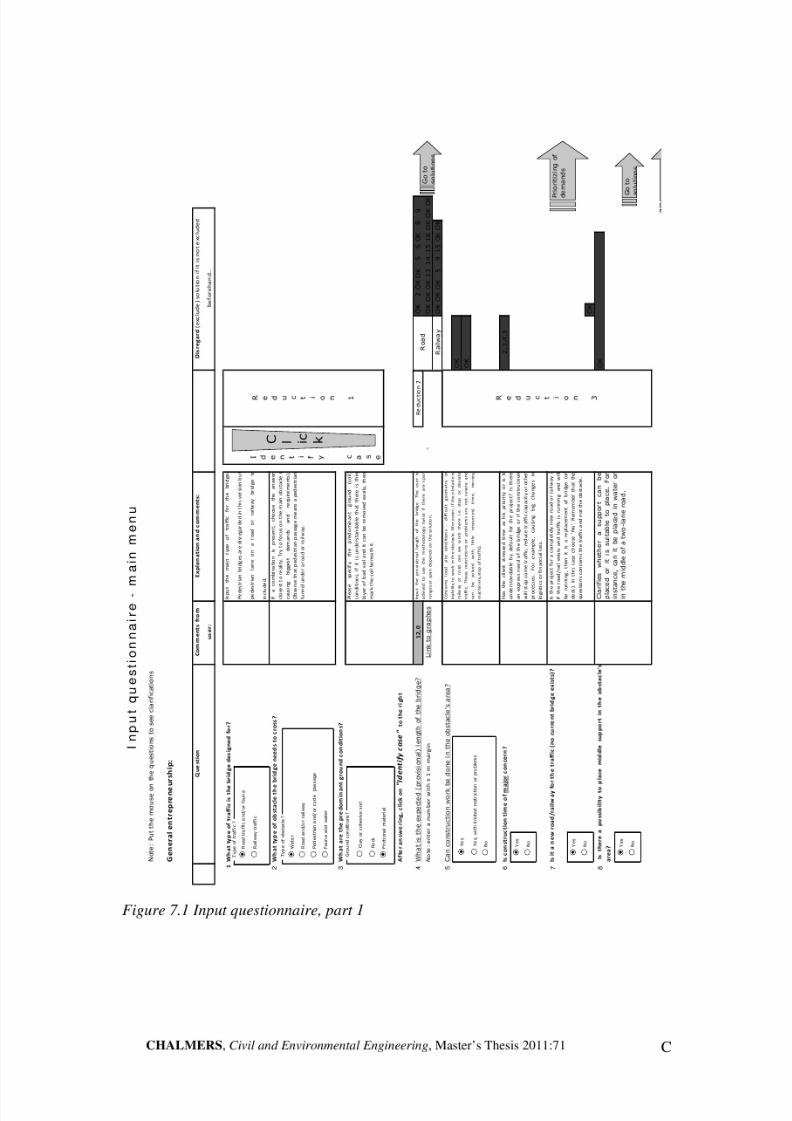
8/2/2019 Guidelines for Conceptual Design Short Span Bridges
http://slidepdf.com/reader/full/guidelines-for-conceptual-design-short-span-bridges 113/131

8/2/2019 Guidelines for Conceptual Design Short Span Bridges
http://slidepdf.com/reader/full/guidelines-for-conceptual-design-short-span-bridges 114/131
D CHALMERS, Civil and Environmental Engineering, Master’s Thesis 2011:71
Figure 7.2 Input questionnaire, part 2
9
W h a t i s t h e n e e d e d b r i d g e s h a p e ( i n t h e h o r i z o n t a l p l a n e ) ?
3
1 0
D o e s t h e b r i d g e n e e d t o b e . . . ?
2
1 1
O t h e r s p e c i a l r e q u i r e m e n t s
Q u e s t i o n s f o r d o c u m e n t a t i o n :
1 2
W h e r e i s t h e b r i d g e s i t u a t e d ?
1
1 0 ? , 1
1 ? , 1
2 ? , 1
3 ? , 1
4 ? , 1
8 ? t i m b e r f i t s d i f f i c u l t l y i n u r b a n e n v i r o n m e n t
1 3
2
O K
( o p t i o n a l )
C O N T I N U E
W h a t i s t h e n e e d e d w i d t h o f t h e b r i d g e o r h o w m a n y l a n e s / l i n e s
a r e n e e d e d ?
R e d u c t i
o n 5 R e d u c t
i o n
4
P l e a s e
w r i t e
d o w n
a n y
o t h e r
r e q u i r e m e n t s
o r
d e m a n d s
f o r
t h e
p r o j e c t . S o m e s p
e c i a l c i r c u m s t a n c e s
c a n b e a d d e d a s w
e l l
U r b a n : c i t y o r v e r y p o p u l a t e d a r e a
H i g h w a y ( s u b u r b a n ) : a r o u n d a h i g h w a y r e g i o n o r i n
t h e
o u t s k i r t s o f c i t y o
r i n d u s t r i a l a r e a
w i t h
l i t t l e
c i t i z e n s
C o u n t r y s i d e : a b r i d g e o u
t s i d e l i v i n g a r e a s ,
m o s t l y o n
i n t e r c i t y r o a d s o r r a i l w a y s
7 , 1
0 , 1
9
O K
6 , 7 , 8 , 9 , 1
0 , 1
1 , 1
2 , 1
3 , 1
4 , 1
6 , 1
7 , 1
8 , 1
9
I f t h e r e
i s
a
r e q u i r e m e n t f r o m
t h e
l a n d s c a p e
a r c h i t
e c t
o r
t h e
c l i e n t .
C o u l d
b e a l s o r e
q u e s t e d
d u e t o
t h e
l o c a l g e o m e t r i c a l c o n d i t i o n s .
I f t h e r e
i s
a
r e q u i r e m e n t f r o m
t h e
l a n d s c a p e a r c h i t e c t o r t h e c l i e n t .
R a n k i n g -
d e t a i l e d
S t r a i g h t
S k e w e
d ( a t a n a n g
l e )
I n a c u r v e
H o r i z o n
t a l o r
i n c
l i n e
d
V e r t i c a
l l y c u r v e
d
B r i d g e
l o c a
t i o n
U r b a n a r e a
H i g h w a y a r e a
C o u n
t r y s i d e
W i d t h o
f b r i d g e
?
s i n g
l e l a n e
/ l i n e
( 2 ÷ 3 ) l a n e s
/ l i n e s
4 l i n e s
/ l a n e s o r m o r e

8/2/2019 Guidelines for Conceptual Design Short Span Bridges
http://slidepdf.com/reader/full/guidelines-for-conceptual-design-short-span-bridges 115/131
CHALMERS, Civil and Environmental Engineering, Master’s Thesis 2011:71 E
Figure 7.3 Span length ranges
№
R O A D T R A F F I C
S t a t u s
P r e s t r .
L e n g t h
2
3
4
5
6
7
8
9
1 0
1 1
1 2
1 3
1 4
1 5
1 6
1 7
1 8
1 9
2 0
2 1
2 2
2 3
2 4
2 5
2 6
2 7
2 8
2 9
3 0
3 1
3 2
3 3
3 4
3 5
№
S o l u t i o n :
[ m ]
1
S l a b - f r a m e i n - s i t u
O K
O K
1 4
1
2
B e a m - f r a m e i n - s i t u
O u t s i d e
O K
1 4
2
3
I n t e g r a l a b u t m e n t s
O K ?
1 4
3
4
S i m p l y s u p p o r t e d s l a b i n - s i t u
O K
O K
1 4
4
5
S i m p l y s u p p o r t e d b e a m i n
- s i t u
O u t s i d e
1 4
5
6
P r e f a b .
h o l l o w c o r e
O u t s i d e
1 4
6
7
P r e f a b . p r e - t e n s i o n e d b e a m s
O K ?
1 4
7
8
P r e f a b . p e d e s t r i a n t u n n e l
O u t s i d e
1 4
8
9
C o r r u g a t e d s t e e l a r c h
O u t s i d e
1 4
9
1 0
S t r e s s - l a m i n a t e d p l a t e
O K
1 4
1 0
1 1
B e a m b
r i d g e w i t h t i m b e r d e c k
O K
1 4
1 1
1 2
B e a m b
r i d g e w i t h L V L d e c k
O K
1 4
1 2
1 3
H a n g i n g t r u s s t i m b e r b r i d g e
O u t s i d e
1 4
1 3
1 4
T i m b e r a r c h b r i d g e
O u t s i d e
1 4
1 4
1 5
S t e e l I - g i r d e r s a n d i n - s i t u R C d e c k
O u t s i d e
1 4
1 5
1 6
S t e e l I - g i r d e r s a n d p r e f a b .
d e c k
O u t s i d e
1 4
1 6
1 7
S t e e l I - g i r d e r s a n d F R P d e c k
O K
1 4
1 7
1 8
T i m b e r g i r d e r s a n d i n - s i t u R C d e c k
O K
1 4
1 8
1 9
" F o l d e d p l a t e s y s t e m "
O K
1 4
1 9
B a c k t o m a i n m e n u
O K
o p t i m a l
O K ?
s a t i s f y i n g ( s o l u t i o n
i s n o t v e r y o p t i m a l )
" O u t s i d e "
n o t s a t i s f y i n g ( n o t a p p r o p r i a t e )
P
p r e s t r e s s i n g a d v i s e d
P +
p r e s t r e s s i n g n e e d e d
№
R A I L W A Y T R A F F I C
S t a t u s
P r e s t r .
L e n g t h
2
3
4
5
6
7
8
9
1 0
1 1
1 2
1 3
1 4
1 5
1 6
1 7
1 8
1 9
2 0
2 1
2 2
2 3
2 4
2 5
2 6
2 7
2 8
2 9
3 0
3 1
3 2
3 3
3 4
3 5
№
S o l u t i o n :
[ m ]
1
S l a b - f r a m e i n - s i t u
O K
O K
1 4
1
2
B e a m - f r a m e i n - s i t u
O K ?
1 4
2
4
S i m p l y s u p p o r t e d s l a b i n - s i t u
O K
O K
1 4
4
5
S i m p l y s u p p o r t e d b e a m i n
- s i t u
O u t s i d e
1 4
5
9
C o r r u g a t e d s t e e l a r c h
O u t s i d e
1 4
9
1 5
S t e e l I - g i r d e r s a n d i n - s i t u R C d e c k
O u t s i d e
1 4
1 5
2 0
T h r o u g h c o n c r e t e b e a m i n
- s i t u ,
f l a t
O K
O K
1 4
2 0
2 1
T h r o u g h c o n c r e t e b e a m i n
- s i t u , r i b b e d
O K
O K
1 4
2 1
S p a n
l e n g t h
r a n
g e s f o r d i f f e r e n t s o l u t i o n s
H i n t : M a r k t h e c o l u m n r e p r e s e n t i n g y o u r i n p u t s p a n f o r e a s i e r v i s u a l i s a t i o n .

8/2/2019 Guidelines for Conceptual Design Short Span Bridges
http://slidepdf.com/reader/full/guidelines-for-conceptual-design-short-span-bridges 116/131

8/2/2019 Guidelines for Conceptual Design Short Span Bridges
http://slidepdf.com/reader/full/guidelines-for-conceptual-design-short-span-bridges 117/131

8/2/2019 Guidelines for Conceptual Design Short Span Bridges
http://slidepdf.com/reader/full/guidelines-for-conceptual-design-short-span-bridges 118/131

8/2/2019 Guidelines for Conceptual Design Short Span Bridges
http://slidepdf.com/reader/full/guidelines-for-conceptual-design-short-span-bridges 119/131
CHALMERS, Civil and Environmental Engineering, Master’s Thesis 2011:71 I
Appendix B: Questionnaires
Summary of questionnaires
NOTE: All the questions concern only short‐span bridges (up to 30 m in
length)
How do you approach conceptual design of bridges? Which guidelines do you use?There are no specific guidelines or procedures, which are used for conceptual
design. Mostly designers use their personal experience keeping in mind for specificproject requirements of the client. If designers don’t have sufficient experience, theydiscuss the project with their senior colleagues. First of all the conceptual design isevaluated in house and then with the owner (client).
In conceptual design the opinion of engineers from other fields also plays animportant role, so for a successful conceptual design the collaboration with road
designers, geotechnical engineers and landscape architects is very important.From client’s point of view the most important requirement is the economy,especially for small bridges where the client is not putting much importance toaesthetics. One problem in conceptual design is how to achieve the cheapest andsimplest design. For example, concrete frame structure is considered the cheapest wayto construct a short span bridge.
What are the most important questions/aspects you need to answer/consider in order
to start your work?The most important aspects that a designer needs to know are the client’s
requirements. After this, the budget for the bridge (including cost of construction and
maintenance) must be known and then aesthetical aspects are considered as well.From aesthetical point of view, the type and location of obstacle is important. Toselect the type of the structural system it is important to know the ground conditionsand expected length (span) of the bridge.
Do you think there is a typical demand/desire that clients want to apply in the projects?
The client always demands an economical solution with high quality and lowmaintenance cost. Bridge engineers come up with a rough cost estimates in MKr/m2.Clients may have some special demands in some cases. For example, for faunabridges the client is more concerned about the shape of the bridge because it should
look natural and welcoming for animals.
How do you achieve/fulfill the above mentioned typical demands?There are different ways to achieve economy. Some of those include:
a) Minimize the surface of the bridge, i.e. shorter spanning bridge.b) Minimize the width of the bridgec) Select a cross section, which is easy to buildd) Simple shape can save the formwork coste) The length is the most efficient way to cut the price

8/2/2019 Guidelines for Conceptual Design Short Span Bridges
http://slidepdf.com/reader/full/guidelines-for-conceptual-design-short-span-bridges 120/131
J CHALMERS, Civil and Environmental Engineering, Master’s Thesis 2011:71
What are the most typical geotechnical conditions you work with? And do they affect
conceptual design?
In Sweden almost all types of soil are present: clay, rock, and frictional material.So, the designer is prepared to handle all kinds of situations. Geotechnical conditionsaffect mostly foundation system and to some extent superstructure.
What are the most typical site conditions/constraints you work with?
It’s hard to define the typical site conditions/constraints. Generally speaking,availability of space and environmental restrictions are the most common constraintsthat designer works with.
How often does a re-design in concept happen and what are the most common
reasons for that (requirements, constraints...)?
Redesign in a concept may happen. Sometimes it is because of a request from theclient. Clients often work simultaneously with the consultancy and make more
research on the specific project. It also happens that consultants propose a changeafter some further considerations. Often the geotechnical data is scarce, and at laterstages of design it becomes clearer. This sometimes provokes changes in concept.
What are the current/nowadays problems in your field that you think should be
improved?
It is very important to find out the current problems in the conceptual design field.On the other hand it’s difficult to come up with one unified answer because it is morerelated to the designer’s personal opinion. However, most of the interviewedspecialists agreed that lack of time for the conceptual design is a common problem. In
most of the cases the time given for conceptual design is very short. To overcome thisproblem, specialists agreed that conceptual design can be optimised and thatknowledge from previous projects needs to be organised in a better way in order tosave time.
Do you have a more preferred material/concept? Why?
Concrete is more preferred material to work with because it’s cheaper. On theother hand it depends on a project-to–project basis. For example, if the span is lessthen 20 m, concrete deck is the most common solution, but if the span length is longerthan 20 m then it’s difficult to handle the self weight of the bridge and lighter materialwould be a better option.
Are there any new technologies, materials you would like to use or experiment with?
In Sweden almost 90 % of all bridges are made from concrete. Steel bridges arenot common for short spans. Some engineers want to try timber bridges for traffic,some would like to work in projects where steel is a major component, and somewould like to work in prefabricated bridges. Moreover, some engineer would like touse or experiment with composite structures like
a) Wood + concreteb) Wood + steelc) Concrete + carbon-fibre composites

8/2/2019 Guidelines for Conceptual Design Short Span Bridges
http://slidepdf.com/reader/full/guidelines-for-conceptual-design-short-span-bridges 121/131
CHALMERS, Civil and Environmental Engineering, Master’s Thesis 2011:71 K
What stopped you in implementing them?
Designers would like to use or experiments with other materials as well but due tolimited time and money available for conceptual design, they have to optimise hislimitations. Moreover, the area of expertise and specialisation of the consultancy is
also one of the factors, which stop designers from implementing the new trends in themarket. For example, firms, which are experts in designing bridges in concrete,always want to have a solution in concrete. Since they have more knowledge anddeveloped procedures, they don’t want to take risks as new trends always need timeand money.
Furthermore, as the common client is currently conservative in spending money,the possible solution to this problem is that the client should invest more in pilot andexperimental projects.
8/2/2019 Guidelines for Conceptual Design Short Span Bridges
http://slidepdf.com/reader/full/guidelines-for-conceptual-design-short-span-bridges 122/131
L CHALMERS, Civil and Environmental Engineering, Master’s Thesis 2011:71
Appendix C: Feedback for the toolbox
From user C1, Eric Lindbom, Ramböll Sverige AB, Gothenburg
What do you think about the methodology which was developed?
I think it can be useful as a supplement in the conceptual design phase. I think themost interesting thing is that it might point out some options that you wouldn’t havethought of otherwise.
Is it user-friendly?Yes, although some of the instructions could be even more descriptive. On the otherhand if you have done it ones, you know it.
Can you point out some questions or navigations, which were confusing?I think I pointed those out when doing the case study.
What drawbacks have you found?The ‘real’ conceptual design process is kind of iterative. For example: the span affectswhich construction type to choose but the construction type might also affect the span.In this aspect the methodology has some limitations.
What do you think about the time to complete? Is it really time taking or rather quick
one?If you know the input data it is quite quick. If you do not know the input data it willtake some time but that means that you are forced to ask yourself or your client thosequestions, which is a good thing.
Do you think it will be useful in your future work? Will you use it in your professionalcarrier?I would like to use it as a supplement in the beginning of a new project to verify theusefulness.
From user C2, Mattias Hansson, Ramböll Sverige AB, Gothenburg
What do you think about the methodology, which was developed?It is useful for documentation and during the work and communication with the client.
Is it user-friendly?It is rather user friendly but I felt that I needed more background knowledge of themethodology behind the toolbox in order to be more effective.
Can you point out some questions or navigations which were confusing?More evaluation is needed in order to know what the effects of certain grades are. The
model should be tested by the user before using it with the client in order to gainconfidence in the relation between input and output.

8/2/2019 Guidelines for Conceptual Design Short Span Bridges
http://slidepdf.com/reader/full/guidelines-for-conceptual-design-short-span-bridges 123/131
CHALMERS, Civil and Environmental Engineering, Master’s Thesis 2011:71 M
What drawbacks have you found?It is quite hard to use all the range of grades (0-4) in the evaluation matrix. It demandsmore experience with the toolbox to get confident in using the full grading system,probably because of the labels of the grading.
What do you think about the time to complete? Is it really time taking or rather quick one?It is very much worth to use it as a background material (documentation) and a headstart for further detailed design. A good overview of the project means security for theclient. The time to use it is well spent.
Do you think it will be useful in your future work? Will you use it in your professional
carrier?It is a new input and useful way of overviewing the different possibilities that theclient is able to continue with in the project.
From user C3, Christer Carlsson, Ramböll Sverige AB, Stockholm
What do you think about the methodology, which was developed?It was done in a proper way covering every kind of option. It provides a very goodstart to reduce the amount of possible solutions (for example, consider five instead of twenty options).
Is it user-friendly?It was quite good. When the user gets used to it, no problems could be expected.
Can you point out some questions or navigations which were confusing?
The grading was not an easy task. Probably only three (1-3) grades would be enoughinstead of 0-4. More grades are definitely not needed.
What drawbacks have you found?The height requirement is not included, i.e. the minimum clearance needed is notreflected in the guidelines. This height affects the choice of solution as well. It is hardto answer and distribute points among flexible parameters.
What do you think about the time to complete? Is it really time taking or rather quick one?I think it took a decent amount of time (40 min) but this was probably because this
was my first encounter with the toolbox.
Do you think it will be useful in your future work? Will you use it in your professionalcarrier?I think it can be very useful as a checklist. The bridge designer could start his work the usual way by proposing a concept he thinks is the most appropriate. After this, hecan use the guidelines to see if anything important is missing or re-evaluate hischoice.

8/2/2019 Guidelines for Conceptual Design Short Span Bridges
http://slidepdf.com/reader/full/guidelines-for-conceptual-design-short-span-bridges 124/131
N CHALMERS, Civil and Environmental Engineering, Master’s Thesis 2011:71
L E V E L 1
L E V E L 2
2 0
6
A 1
A 2
A 3
A 4
A 5
A 6
B 1
B 2
B 3
B 4
B 5
B 6
B 7
B 8
L E V E L 3
7 0
4 , 2 0
3 0
1 , 8 0
7 0
1 2
, 6 0
3 0
5 , 4 0
5 0
3 , 0 0
5 0
3 , 0 0
4 0
1 4 , 0 0
2 5
8 , 7 5
3 5
1 2 , 2 5
6 0
8
, 4 0
4 0
5 , 6 0
4 0
8 , 4 0
2 0
4 , 2 0
4 0
8 , 4 0
2 0
6
G o o d
d y n a m i c
b e h a v i o u r
S u p e r i o r
d u r a b i l i t y
B
a s i c v a l u e s
A e s t
h e t
i c a
l d e s
i g n
E n v
i r o n m
e n t a
l
S
e r v
i c e
l i f e
F l e x i b
l e
p a r a m
e t e r s
7 0
7 0
R o b u s t n e s s
S h o r t
c o n s t r u c t i o n
t i m e
F l e x i b i l i t
y
d u r i n g d e s
i g n
P e r
f o r m
a n c e
S t r u
c t u r a
l d e s
i g n
5 0
C o n s t r u c t i o n
s i m p l i c i t y
1 4
3 0
2 1
L o w
s e l f
w e i g h t
F l e x i b i l i t y
d u r i n g
c o n s t r u c t i o n
P r o
d u c t
i o n
2 0
3 5
F i x e
d
p a r a m
e t e r s
I n n o v a t i v e
d e s i g n
S u s t a i n a b i l i t y
I m p a c t
d u r i n g
c o n s t r u c t i o n
E x p a n d i n g
p o s s i b i l i t i e s
R e d u c e d
m a i n t e n a n
c e
c o s t s
A d d e d v
a l u e s o r s t r e s s o n
p a r a m e t e r s
3 0
A e s t h e t i c s
3 0
6 0
1 8
Appendix D: Case study results
Case study one: Backaå
Figure 7.7 ‘Objective tree’ for case study one, Backaå. User C1 (left), C2 (right)
L E V E L
1
L E V E L
2
2 0
1 0
A 1
A 2
A 3
A 4
A 5
A 6
B 1
B 2
B 3
B 4
B 5
B 6
B 7
B 8
L E V E L
3
5 0
5 , 0 0
5 0
5 , 0 0
5 0
1 2 , 5
0
5 0
1 2 , 5 0
5 0
7 , 5 0
5 0
7 , 5 0
3
3
6 , 6 0
3 3
6 , 6 0
3 4
6 , 8 0
5 0
5 , 0 0
5 0
5 , 0 0
3 3
6 , 6 0
3 3
6 , 6 0
3 4
6 , 8 0
3 0
1 5
G o o d
d y n a m i c
b e h a v i o u r
S u p e r i o r
d u r a b i l i t y
R o b
u s t n e s s
S h o r t
c o n s t r u c t i o n
t i m e
F l e x i b i l i t y
d u r i n g d e s i g n
A e s t
h e t
i c a
l d e s
i g n
E n v
i r o n m
e n t a
l
S e
r v
i c e
l i f e
F l e x
i b l e
p a r a m
e t e r s
B a s i c v
a l u e s
C o n s t r u c t i o n
s i m p l i c i t y
1 0
4 0
2 0
L o w
s e l f
w e i g h t
F l e x i b i l i t y
d u r i n g
c o n s t r u c t i o n
F i x e
d
p a r
a m
e t e r s
5 0
5 0
P e r
f o r m
a n c e
S t r u c t u r a
l d e s
i g n
4 0
I n n o v a t i v e
d e s i g n
S u s t a i n a b i l i t y
I m p a c t
d u r i n g
c o n s t r u c t i o n
E x p a n d i n g
p o s s i b i l i t i e s
R e d u c e d
m a i n t e n a n c e
c o s t s
A d d e d v a l u e s o r s t r e s s o n
p a
r a m e t e r s
5 0
A e s t h e t i c s
5 0
5 0
2 5
P r o
d u c t
i o n
2 0
2 0

8/2/2019 Guidelines for Conceptual Design Short Span Bridges
http://slidepdf.com/reader/full/guidelines-for-conceptual-design-short-span-bridges 125/131
CHALMERS, Civil and Environmental Engineering, Master’s Thesis 2011:71 O
Figure 7.8 Results for user C1

8/2/2019 Guidelines for Conceptual Design Short Span Bridges
http://slidepdf.com/reader/full/guidelines-for-conceptual-design-short-span-bridges 126/131
P CHALMERS, Civil and Environmental Engineering, Master’s Thesis 2011:71
Figure 7.9 Results for user C2

8/2/2019 Guidelines for Conceptual Design Short Span Bridges
http://slidepdf.com/reader/full/guidelines-for-conceptual-design-short-span-bridges 127/131
CHALMERS, Civil and Environmental Engineering, Master’s Thesis 2011:71 Q
Values com parison
0,0
50,0
100,0
150,0
A e s t h e t i c a l
d e s i g n
S e r v i c e
l i f e
E n v i r o n m
e n t a l
P e r f o r m a n
c e
S t r u c t u r a l d
e s i g n
P r o d
u c t i o
nObjectives
Weighted value
1
4
6
10
17
Values com parison
0,0
50,0
100,0
150,0
A e s t h e t i c a l
d e s i g n
S e r v i c e
l i f e
E n v i r o n m
e n t a l
P e r f o r m a n
c e
S t r u c t u r a l
d e s i g n
P r o d
u c t i o
nObjectives
Weighted value
4
6
9
10
17
Figure 7.10 Value comparison for Backån. User C1 (above), C2 (below)

8/2/2019 Guidelines for Conceptual Design Short Span Bridges
http://slidepdf.com/reader/full/guidelines-for-conceptual-design-short-span-bridges 128/131
R CHALMERS, Civil and Environmental Engineering, Master’s Thesis 2011:71
Over al l r esult
212
194
173
202193
0 00
50
100
150
200
250
1 4 6 10
Solut ion
S c o r e
Over al l r esult
285
200
365345
245
0 00
50
100
150
200
250
300
350
400
4 6 9 10
Solut ion
S c o r e
Figure 7.11 Comparative tables for the final results. User C1 (above), C2 (below)

8/2/2019 Guidelines for Conceptual Design Short Span Bridges
http://slidepdf.com/reader/full/guidelines-for-conceptual-design-short-span-bridges 129/131
CHALMERS, Civil and Environmental Engineering, Master’s Thesis 2011:71 S
Case study two: Bräcke bridge
Figure 7.12 ‘Objective tree’ for Bräcke bridge.
L E V E L
1
L E V E L
2
1 0
5
A 1
A 2
A 3
A 4
A 5
A 6
B 1
B 2
B 3
B 4
B 5
B 6
B 7
B 8
L E V E L
3
5 0
2 , 5
0
5 0
2 , 5
0
5 0
1 5 , 0
0
5 0
1 5
, 0 0
5 0
7 , 5
0
5 0
7 , 5
0
3 3
9 , 9
0
3 3
9 , 9
0
3 4
1 0
, 2 0
5 0
2 , 5
0
5 0
2 , 5
0
3 3
4 , 9
5
3 3
4 , 9
5
3 4
5 , 1
0
3 0
1 5
G o o
d
d y n a m
i c
b e
h a v
i o u r
S u p e r i o r
d u r a
b i l i t y
R o
b u s
t n e s s
S h o r t
c o n s
t r u c
t i o n
t i m e
F l e x
i b i l i t y
d u r i n g
d e
s i g n
A e s t
h e t
i c a
l d e s
i g n
E n v
i r o n m
e n t a
l i s s u e s
S e r v
i c e
l i
f e
a d d e
d
v a
l u e s
F l e x
i b l e
p a r a m
e t e r s
B a s
i c v a
l u e s
L o w
s e
l f
w e
i g h t
5
3 0
1 5
C o n s
t r u c
t i o n
s i m p
l i c i t y
F l e x
i b i l i t y
d u r i n g
c o n s
t r u c
t i o n
F i x
e d
p a r a m
e t e r s
5 0
5 0
P e r
f o r m
a n c e
S t r
u c t u r a
l d e s
i g n
6 0
I n n o v a
t i v e
d e s
i g n
S u s
t a i n a
b i l i t y
I m p a c
t
d u r i n g
c o n s
t r u c
t i o n
E x p a n
d i n g
p o s s
i b i l i t i e s
R e
d u c e
d
m a
i n t e n a n c
e
c o s
t s
A d d e
d v a
l u e s o r s
t r e s s o n
p a
r a m e
t e r s
5 0
A e s
t h e
t i c s
5 0
6 0
3 0
P r o
d u c t
i o n
1 0
3 0

8/2/2019 Guidelines for Conceptual Design Short Span Bridges
http://slidepdf.com/reader/full/guidelines-for-conceptual-design-short-span-bridges 130/131
T CHALMERS, Civil and Environmental Engineering, Master’s Thesis 2011:71
Figure 7.13 Ranking (evaluation) matrix for Bräcke bridge.
G r a d e
P o i n t s
G r a d e
P o i n t s
G r a d e
P o i n t s
G r a d e
P o i n t s
G r a d
e
P o i n t s
G r a d e
P o i n t s
G r a d e
P o i n t s
R e s e t
R u n
B a c k t o m a i n m e n u
G r a d i n g
s y s t e m
:
0 U n s a t i s f a c t o r y
1 J u s t t o l e r a b l e
2 A d e q u a t e
3 G o o d
2 .
I n p u t g r a d e i n h o r i z o n t a l o r d e r i . e . g i v e a l l g
r a d e s f o r " A e s t e t i c a l d e s i g n " t o a l l s o l u t i o n s .
4 V e r y g o o d ( i d e a l )
3 .
C l i c k o n t h e g r e e n a r r o w t o R u n t h e p r o g r a m
. T h e b e s t a l t e r n a t i v e w i l l b e h i g h l i g h t e n e d g r e
e n .
4 .
Y o u c a n a l w a y s m a k e c h a n g e s t o t h e g r a d e s .
T o r e s e t t h e p r o c e d u r e , c l i c k o n t h e a r r o w " R e
s e t " .
5 .
W r i t e c o m m e n t s f o r e a c h g r a d e t o e x p l a i n y o
u r i n p u t .
0 .
W r i t e d o w n w h i c h s o l u t i o n s a r e l e f t ( n u m b e r
s o r c h o o s e t h e d r o p l i s t ) .
1 .
I n
t h e
" G r a d e "
c o l u m n s
i n s e r t n u m b e r
f r o m
( 0 ÷ 4 )
g r a d i n g
a l t e r n a t i v e s
a c c o r d i n g t o d i f f e r e n t p a r a m e t e r s .
0
0 , 0
0
0 , 0
0
0 , 0
0
0 , 0
0
0
0
0 , 0
0
0
0 , 0
0
0
0 , 0
0
0
0 , 0
0
0
0 , 0
0
0
0 , 0
0
0
0 , 0
0
0
0 , 0
0
0
0 , 0
0
0
0 , 0
0
A d d i t i o n a l s o l u t i o n s
F i l l i n … .
F i l l i n … .
3 , 1
5
2 , 6
0
3 , 4
5
3 , 7
0
3 , 5
0
H o w
t o
u s e
t h e
t r e e :
F i n a l
g r a d e
A e s t h e t i c a l
d e s i g n
S e r v i c e l i f e
a d d e d v a l u e s
E n v i r o n m e n t a l
i s s u e s
P e r f o r m a n c e
D E M A N D S
0 , 0
5 0
0 , 1
5 0
4
4
W e i g h t i n g
c o e f f i c i e n t
A l t e r n a t i v e s
1
2
4
S t r u c t u r a l
d e s i g n
H i n t :
P u t
a
g r a d e
f r o m
( 0 ÷ 4 )
t o
e a c h
p a r a m e t e r
f o r e a c h a l t e r n a t i v e .
F i x e d F l e x i b l e
0 , 3
0 0
4 3
P r o d u c t i o n
0 , 0
5 0
0 , 3
0 0
0 , 1
5 0
4 3
0 , 2
0
0 , 4
5
0 , 1
5
0 , 3
0
1 , 2
0
0 , 4
5
1 , 2
0
4 4 3 4
0 , 2
0
1 , 2
0
0 , 4
5
1 , 2
0
4 4 3 2 4
3 3
0 , 4
5
1 , 2
0
0 , 1
5
0 , 4
5
3 4
0 , 4
5
3 4 3 4
0 , 6
0
0 , 1
5
0 , 2
0
3 4
0 , 3
0
B a c k t o o b j e c t i v e t r e e
3 2
0 , 1
0
0 , 6
0
3 2
0 , 2
0
2
3
4
5
0 , 1
5
0 , 1
5
1 , 2
0
0 , 4
5
1 , 2
0
0 , 2
0
1 , 2
0
S l a b f r a m e
i n - s
i t u
B e a m - f r a m e
i n - s
i t u
I n t e g r a
l a
b u
t m e n
t s
S i m p
l y s u p p o r t e
d s l a
b i n - s
i t u
S i m p
l y s u p
p o r t e
d b e a m
i n - s
i t u
S i m p
l y s u p
p o r t e
d b e a m
i n - s i t u

8/2/2019 Guidelines for Conceptual Design Short Span Bridges
http://slidepdf.com/reader/full/guidelines-for-conceptual-design-short-span-bridges 131/131
Values compar ison
0,00
0,50
1,00
1,50
2,00
A e s t h e t i c a l
d e s i g n
S e r v i c e l i
f e a d d
e d v a l u e
s
E n v i r
o n m e n
t a l i s s u e
s
P e r f o r m a n
c e
S
t r u c t u r a l d
e s i g n
P r o d
u c t i o
nObjectives
Weighted value
1
2
3
4
5