guidelines for selecting solid-state lighting for museums · 2019-08-06 · luminous efficacy ......
TRANSCRIPT
James R. Druzik and Stefan W. Michalski
C a n a d i a n C o n s e r v a t i o n I n s t i t u t e T h e G e t t y C o n s e r v a t i o n I n s t i t u t e J u
Guidelines for Selecting Solid-State Lighting for Museums
August 2012
2
© 2012 J. Paul Getty Trust and Canadian Conservation Institute
The Getty Conservation Institute
1200 Getty Center Drive, Suite 700
Los Angeles, CA 90049-1684
United States
Telephone 310 440-7325
Fax 310 440-7702
E-mail [email protected]
www.getty.edu/conservation
Canadian Conservation Institute
1030 Innes Road
Ottawa, Ontario K1A 0M5
Canada
Telephone 613 998-3721
Fax 613 998-4721
www.cci-gc.ca
The Getty Conservation Institute works internationally to advance conservation
practice in the visual arts—broadly interpreted to include objects, collections,
architecture, and sites. The GCI serves the conservation community through
scientific research, education and training, model field projects, and the
dissemination of the results of both its own work and the work of others in the field.
In all its endeavors, the GCI focuses on the creation and delivery of knowledge that
will benefit the professionals and organizations responsible for the conservation of
the world’s cultural heritage.
3
A Users Guide for Selecting Solid-State Lighting for Museum Use Table of Contents
Acknowledgments ......................................................................................................................................................4 Introduction ..................................................................................................................................................................5
SECTION 1: What’s an LED and how does it differ from traditional lighting? .................. 6
How LEDs fit into sustainability goals for museums ...................................................... 8 Comparison of LEDs to traditional lighting .................................................................................................. 11
Luminous efficacy ........................................................................................................................................................ 11 Life span and Lumen Maintenance ...................................................................................................................... 11 Correspondent properties ........................................................................................................................................ 12 Color Rendering Index (CRI) ................................................................................................................................... 13 Color consistency and appearance over time ................................................................................................. 14 Form Factor (retrofit versus dedicated LED design) .................................................................................. 16 Cost and ROI Payback ................................................................................................................................................ 17 Mature versus evolving technologies .................................................................................................................. 18 Controlling Glare .......................................................................................................................................................... 19 Blue versus violet chip-driven LEDs .................................................................................................................... 20 Dimming and Flicker .................................................................................................................................................. 21 Thermal Management ............................................................................................................................................... 21 Replacing T12 Fluorescent Lamps ....................................................................................................................... 22
LED Decision-Making In a Nutshell ............................................................................. 22
SECTION 2: Making the Decision: Which LEDs Products to Buy .................................... 23
REVIEW...................................................................................................................... 23
READ ......................................................................................................................... 24 Product Testing (CALiPER) ..................................................................................................................................... 24 IES LM-79......................................................................................................................................................................... 24 IES LM-80......................................................................................................................................................................... 25 GATEWAY Demonstration ....................................................................................................................................... 25 ENERGY STAR ................................................................................................................................................................ 26 Lighting Facts Labels ................................................................................................................................................. 26
LOOK ......................................................................................................................... 26
AGREE ....................................................................................................................... 30 Recap: Getting the Most Out of Your LED Products .................................................................................. 32
SECTION 3: A CCI Guide to Best Practices in Lighting Policy and Practice ..................... 33 Sources for Solid-State Lighting Products Described in this Document ........................................... 49 U.S. Department of Energy Internet Resources........................................................................................... 51 Bibliography .............................................................................................................................................................. 52
Appendix 1.Visual Comparison of Color Rendering Lamp Ratings ................................ 54
4
Acknowledgments Much of the information in this guideline is taken from programs created by and for the United States Department of Energy, Lighting Research and Development Building Technologies Program. The authors are particularly in debt to Naomi Miller, Senior Lighting Engineer, Pacific Northwest National Laboratory whose insights and suggestions were invaluable to virtually all sections of this document. Ken Kane, Lighting Services, Inc. and Ron Steen of Xicato have provided difficult to find information into the strength and limitation of warranties when purchasing LED lighting from the manufacturer’s point of view. Further manufacturing insights came from Mark Sieber, Tom Healy, and Valerie Khiaban from ERCO Lighting, Inc.; Chip Richards and Gary Allen from GE Lighting Solutions; and Brenda Baldwin from LEDnovation, Inc. I’m particularly in debt to GE for sharing with me their engineering insights on color mixing and reduce glare design. For advice on lighting design we appreciate our many conversations with Scott Rosenfeld, lighting designer at the Smithsonian American Art Museum. Christopher Cuttle, Lighting Consultant, New Zealand, has provided many useful comments and observations and has been a close associate for a number of years. We also appreciate the help of Harold Murray, P. Eng., LC LEED AP, Ameresco Canada, Toronto, Ontario, Canada, who has offered his observations on dimming. As far as we know, Richard Kerschner, Director of Preservation and Conservation at the Shelburne Museum, has the distinction of being one of the first, if not the first, adopter of LED lighting in an American museum. The fruits of his experience can also be found in this document. We also thank Salvador Muñoz Viñas for also reading the manuscript from the conservator’s point of view. Lastly, we’d like to thank our colleagues at the Getty Conservation Institute and the Canadian Conservation Institute for making projects like this possible, including Kevin Marshall and Thomas Kren, and to all the numerous company representatives in the lighting industry who shared their products with us for laboratory testing. This document was originally prepared for a lighting workshop conducted at the Canadian Conservation Institute in the summer of 2011. We likewise appreciate the advice and questions of those workshop participants.
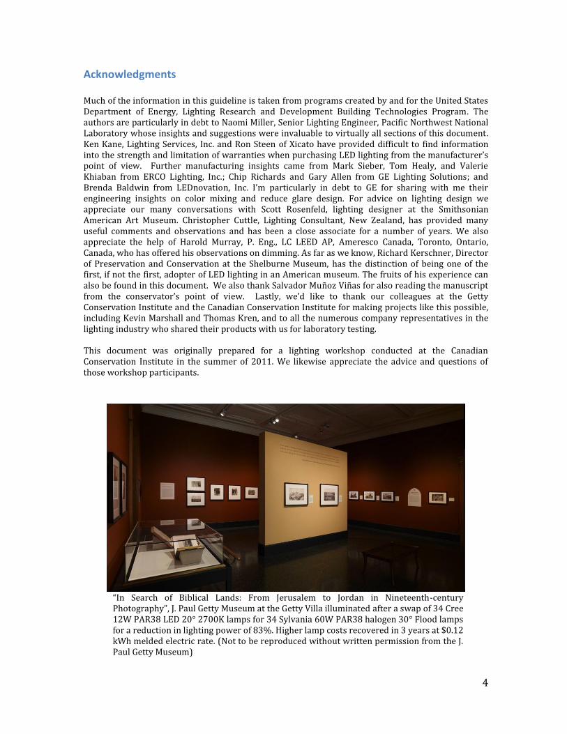
“In Search of Biblical Lands: From Jerusalem to Jordan in Nineteenth-century Photography”, J. Paul Getty Museum at the Getty Villa illuminated after a swap of 34 Cree 12W PAR38 LED 20° 2700K lamps for 34 Sylvania 60W PAR38 halogen 30° Flood lamps for a reduction in lighting power of 83%. Higher lamp costs recovered in 3 years at $0.12 kWh melded electric rate. (Not to be reproduced without written permission from the J. Paul Getty Museum)
5
A Users Guide for Selecting Solid-State Lighting for Museum Use
In 2012 the United States will consume 10 quads of electrical power on general illumination. From 2010 to 2030 it is estimated that a national SSL program could save 16 quads in energy. 1 quad is the equivalent of one quadrillion BTUs or roughly 36 million tons of coal or one trillion cubic feet of natural gas.
Introduction The process of selecting solid-state lighting (SSL) products for museums can be an intimidating experience. But by following four reasonable steps that process can be simplified into an organized search of discovery that will be enriching and hopefully enjoyable. In Section 1, this document begins by giving a simplified outline of how SSL, and light-emitting diodes (LEDs) in particular, work, their performance parameters, and what can go wrong with them. If all you want is a quick answer to the question, “Are LEDs safe and effective in museums, and how do I evaluate them?” jump to the end of Section 1 and read LED Decision-Making In a Nutshell. If you are called upon to assist in a central role selecting, evaluating and purchasing SSL products, Section 2 will then lead you through the process of learning how to REVIEW the uses in museums where SSL may be applied, realizing that the requirements for general illumination may not be the same as those for gallery installations. We’ll then summarize the many written reports and programs that have been created to provide the consumer with high quality information on SSL performance criteria. Selectively READ those documents that align most closely with your interest. Most museum staff will be able to appreciate the GATEWAY demonstration project reports, but facilities managers and in-house lighting specialist might be better suited to consult on fact sheets, standards and specifications and particularly CALiPER reports which provide independent laboratory testing of each product. We’ll explain what those reports cover.
Color in SSL products is a significant factor in making a final aesthetic decision on what to buy and for what to illuminate. While color in SSL is not any greater than more traditional types of museum lighting, it certainly may appear that way. In the final analysis you may decide on several types of lamps, from different manufacturers, in at least two or more color temperatures. They will likely all look slightly different. Always LOOK at all the options and we’ll describe several methods to maximize that evaluation. Finally, SSL is currently more expensive than other forms of common illumination. Therefore you will not want to consider simple replacement at your own expense if a lamp does not meet your expectations, if it fails catastrophically, or if it changes color in an unacceptable manner during use. A manufacturer who produces a top tier LED product intended for museums or other high-end users should be expected to stand behind their product’s performance. That is why it is important to AGREE on those conditions well in advance of any purchase. Many manufacturers will give a three or even five-year written warranty.
We shall end with a review of techniques for getting the best results using LEDs. You will also see that LEDs fit into any lighting risk management or preventive conservation program seamlessly.
6
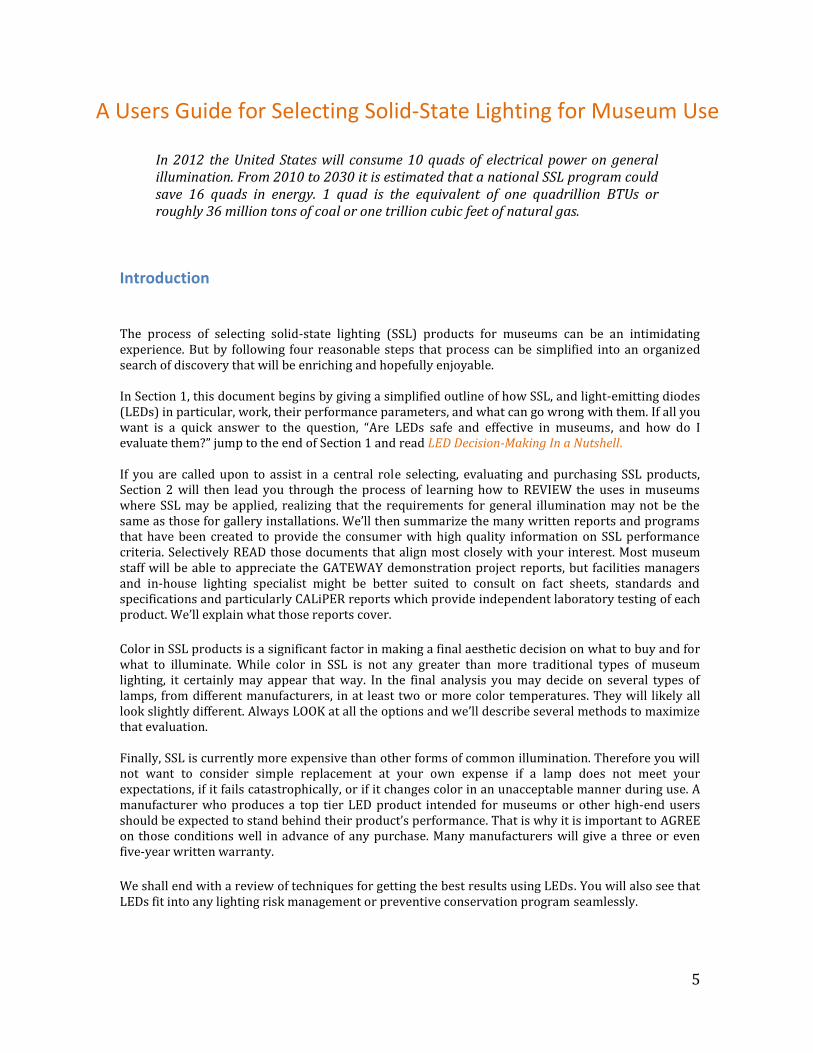
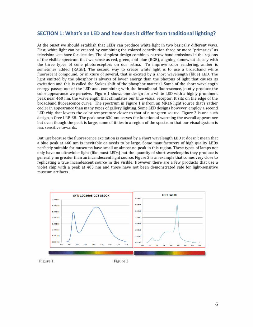
SECTION 1: What’s an LED and how does it differ from traditional lighting? At the onset we should establish that LEDs can produce white light in two basically different ways. First, white light can be created by combining the colored contribution three or more “primaries” as television sets have for decades. The simplest design combines narrow band emissions in the regions of the visible spectrum that we sense as red, green, and blue (RGB), aligning somewhat closely with the three types of cone photoreceptors on our retina. To improve color rendering, amber is sometimes added (RAGB). The second way to create white light is to use a broadband white fluorescent compound, or mixture of several, that is excited by a short wavelength (blue) LED. The light emitted by the phosphor is always of lower energy than the photons of light that causes its excitation and this is called the Stokes shift of the phosphor material. Some of the short wavelength energy passes out of the LED and, combining with the broadband fluorescence, jointly produce the color appearance we perceive. Figure 1 shows one design for a white LED with a highly prominent peak near 460 nm, the wavelength that stimulates our blue visual receptor. It sits on the edge of the broadband fluorescence curve. The spectrum in Figure 1 is from an MR16 light source that’s rather cooler in appearance than many types of gallery lighting. Some LED designs however, employ a second LED chip that lowers the color temperature closer to that of a tungsten source. Figure 2 is one such design, a Cree LRP-38. The peak near 630 nm serves the function of warming the overall appearance but even though the peak is large, some of it lies in a region of the spectrum that our visual system is less sensitive towards.
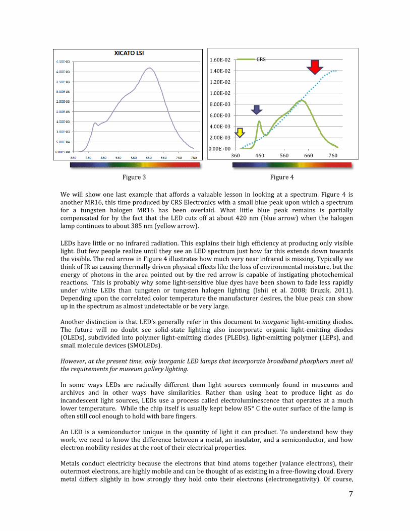
But just because the fluorescence excitation is caused by a short wavelength LED it doesn’t mean that a blue peak at 460 nm is inevitable or needs to be large. Some manufacturers of high quality LEDs perfectly suitable for museums have small or almost no peak in this region. These types of lamps not only have no ultraviolet light (like most LEDs) but the quantity of short wavelengths they produce is generally no greater than an incandescent light source. Figure 3 is an example that comes very close to replicating a true incandescent source in the visible. However there are a few products that use a violet chip with a peak at 405 nm and those have not been demonstrated safe for light-sensitive museum artifacts.
Figure 1 Figure 2
7
Figure 3 Figure 4
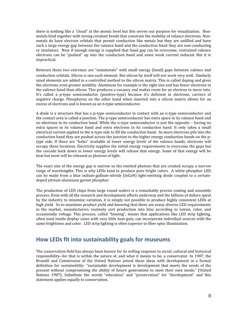
We will show one last example that affords a valuable lesson in looking at a spectrum. Figure 4 is another MR16, this time produced by CRS Electronics with a small blue peak upon which a spectrum for a tungsten halogen MR16 has been overlaid. What little blue peak remains is partially compensated for by the fact that the LED cuts off at about 420 nm (blue arrow) when the halogen lamp continues to about 385 nm (yellow arrow).
LEDs have little or no infrared radiation. This explains their high efficiency at producing only visible light. But few people realize until they see an LED spectrum just how far this extends down towards the visible. The red arrow in Figure 4 illustrates how much very near infrared is missing. Typically we think of IR as causing thermally driven physical effects like the loss of environmental moisture, but the energy of photons in the area pointed out by the red arrow is capable of instigating photochemical reactions. This is probably why some light-sensitive blue dyes have been shown to fade less rapidly under white LEDs than tungsten or tungsten halogen lighting (Ishii et al. 2008; Druzik, 2011). Depending upon the correlated color temperature the manufacturer desires, the blue peak can show up in the spectrum as almost undetectable or be very large. Another distinction is that LED’s generally refer in this document to inorganic light-emitting diodes. The future will no doubt see solid-state lighting also incorporate organic light-emitting diodes (OLEDs), subdivided into polymer light-emitting diodes (PLEDs), light-emitting polymer (LEPs), and small molecule devices (SMOLEDs). However, at the present time, only inorganic LED lamps that incorporate broadband phosphors meet all the requirements for museum gallery lighting. In some ways LEDs are radically different than light sources commonly found in museums and archives and in other ways have similarities. Rather than using heat to produce light as do incandescent light sources, LEDs use a process called electroluminescence that operates at a much lower temperature. While the chip itself is usually kept below 85° C the outer surface of the lamp is often still cool enough to hold with bare fingers. An LED is a semiconductor unique in the quantity of light it can product. To understand how they work, we need to know the difference between a metal, an insulator, and a semiconductor, and how electron mobility resides at the root of their electrical properties. Metals conduct electricity because the electrons that bind atoms together (valance electrons), their outermost electrons, are highly mobile and can be thought of as existing in a free-flowing cloud. Every metal differs slightly in how strongly they hold onto their electrons (electronegativity). Of course,
0.00E+00
2.00E-03
4.00E-03
6.00E-03
8.00E-03
1.00E-02
1.20E-02
1.40E-02
1.60E-02
360 460 560 660 760
CRS
8
there is nothing like a “cloud” at the atomic level but this serves our purpose for visualization. Non-metals bind together with strong covalent bonds that constrain the mobility of valance electrons. Non-metals do have electron orbitals that permit conduction like metals but they are unfilled and have such a large energy gap between the valance band and the conduction band they are non-conducting or insulators. Now if enough energy is supplied that band gap can be overcome, restrained valence electrons can be “pushed” up into the conduction band and some weak current induced. But it is impractical. Between these two extremes are “semimetals” with small energy (band) gaps between valence and
conduction orbitals. Silicon is one such element. But silicon by itself will not work very well. Similarly sized elements are added in a controlled method to the silicon matrix. This is called doping and gives the electrons even greater mobility. Aluminum for example is the right size and has fewer electrons in the valence band than silicon. This produces a vacancy and makes room for an electron to move into. It’s called a p-type semiconductor (positive-type) because it’s deficient in electrons, carriers of negative charge. Phosphorus on the other hand when inserted into a silicon matrix allows for an excess of electrons and is known as an n-type semiconductor. A diode is a structure that has a p-type semiconductor in contact with an n-type semiconductor and the contact area is called a junction. The p-type semiconductor has extra space in its valance band and no electrons in its conduction band. While the n-type semiconductor is just the opposite – having no extra spaces in its valance band and extra electrons in its conduction band. It only takes a small electrical current applied to the n-type side to fill the conduction band. As more electrons pile into the conduction band they are pushed across the junction to the higher energy conduction bands on the p-type side. If there are “holes” available at lower energy levels of the valence bands, electrons will occupy these locations. Electricity supplies the initial energy requirements to overcome the gaps but the cascade back down to lower energy levels will release that energy. Some of that energy will be heat but most will be released as photons of light.
The exact size of the energy gap is narrow so the emitted photons that are created occupy a narrow range of wavelengths. This is why LEDs tend to produce pure bright colors. A white phosphor LED can be made from a blue indium-gallium-nitride (InGaN) light-emitting diode coupled to a cerium-doped yttrium aluminum garnet phosphor.
The production of LED chips from large round wafers is a remarkably precise coating and assembly process. Even with all the research and development efforts underway and the billions of dollars spent by the industry to minimize variation, it is simply not possible to produce highly consistent LEDs at high yield. So to maximize product yield and knowing that there are many diverse LED requirements in the market, manufacturers routinely sort production into bins according to lumen, color, and occasionally voltage. This process, called “binning”, means that applications like LED strip lighting, often used inside display cases with very little heat gain, can incorporate individual sources with the same brightness and color. LED strip lighting is often superior to fiber optic illumination.
How LEDs fit into sustainability goals for museums The conservation field has always been known for its willing response to social, cultural and historical responsibility--for that is within the nature of, and what it means to be, a conservator. In 1987, the Brundtl and Commission of the United Nations joined those ideas with development in a formal definition for sustainability: “sustainable development is development that meets the needs of the present without compromising the ability of future generations to meet their own needs.” (United Nations 1987). Substitute the words “education” and “preservation” for “development” and this statement applies equally to conservation.
9
During the 37th Annual Meeting of the American Institute for Conservation in Los Angeles, 2009, the Green Task Force presented the results of a survey it conducted of its members regarding green practices in museums. After recycling, the second most dominant theme called for a reduction in energy consumption. The survey report noted that 55% of conservator’s workplaces still used incandescent lighting with compact fluorescent (CFL) and T8 tube fluorescents on the rise in use. LED’s in exhibit situations trailed.
The Energy Independence and Security Act of 2007 (EISA), in the United States, has mandated the elimination of old style incandescent lamps by 2014 in specifying lower new maximum rated wattages. These lower wattages apply to general service incandescent lamps. Reflector lamps such as BR, ER, and BPAR and lamps between 2.25 and 2.75 inches now have the same minimum average lamps efficiencies established for R and PAR lamps in 1992. There are twenty-two types of incandescent lamps that have bee exempted from the 2007 tighter controls. The Department of Energy will monitor the sales of these lamps and if their sales doubles, EISA requires the DOE to establish an energy conservation standard for that lamp. California has stricter rules with their elimination by 2013, and in Canada by 2012. In other parts of the world the move away from inefficient lighting is even faster. In Europe, EU Directive 2005/32/EC by the Ecodesign Regulatory Committee (IP/08/12/2008) plans that the European production of tungsten light bulbs will be phased out between 2009 and 2012. Similar action is going on in Australia. The Energy Efficiency Regulations are published on the Natural Resources Canada website.
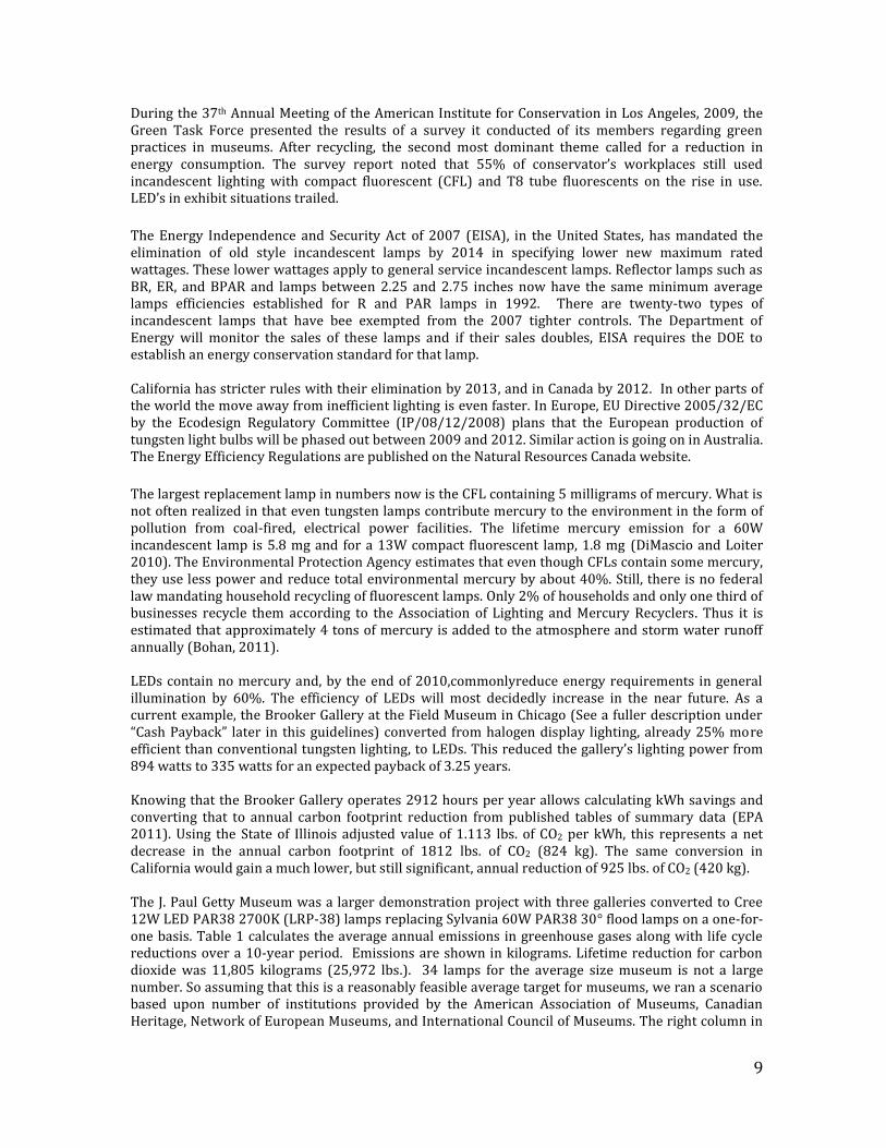
The largest replacement lamp in numbers now is the CFL containing 5 milligrams of mercury. What is not often realized in that even tungsten lamps contribute mercury to the environment in the form of pollution from coal-fired, electrical power facilities. The lifetime mercury emission for a 60W incandescent lamp is 5.8 mg and for a 13W compact fluorescent lamp, 1.8 mg (DiMascio and Loiter 2010). The Environmental Protection Agency estimates that even though CFLs contain some mercury, they use less power and reduce total environmental mercury by about 40%. Still, there is no federal law mandating household recycling of fluorescent lamps. Only 2% of households and only one third of businesses recycle them according to the Association of Lighting and Mercury Recyclers. Thus it is estimated that approximately 4 tons of mercury is added to the atmosphere and storm water runoff annually (Bohan, 2011). LEDs contain no mercury and, by the end of 2010,commonlyreduce energy requirements in general illumination by 60%. The efficiency of LEDs will most decidedly increase in the near future. As a current example, the Brooker Gallery at the Field Museum in Chicago (See a fuller description under “Cash Payback” later in this guidelines) converted from halogen display lighting, already 25% more efficient than conventional tungsten lighting, to LEDs. This reduced the gallery’s lighting power from 894 watts to 335 watts for an expected payback of 3.25 years. Knowing that the Brooker Gallery operates 2912 hours per year allows calculating kWh savings and converting that to annual carbon footprint reduction from published tables of summary data (EPA 2011). Using the State of Illinois adjusted value of 1.113 lbs. of CO2 per kWh, this represents a net decrease in the annual carbon footprint of 1812 lbs. of CO2 (824 kg). The same conversion in California would gain a much lower, but still significant, annual reduction of 925 lbs. of CO2 (420 kg). The J. Paul Getty Museum was a larger demonstration project with three galleries converted to Cree 12W LED PAR38 2700K (LRP-38) lamps replacing Sylvania 60W PAR38 30° flood lamps on a one-for-one basis. Table 1 calculates the average annual emissions in greenhouse gases along with life cycle reductions over a 10-year period. Emissions are shown in kilograms. Lifetime reduction for carbon dioxide was 11,805 kilograms (25,972 lbs.). 34 lamps for the average size museum is not a large number. So assuming that this is a reasonably feasible average target for museums, we ran a scenario based upon number of institutions provided by the American Association of Museums, Canadian Heritage, Network of European Museums, and International Council of Museums. The right column in
10
Table 1 provides life cycles carbon dioxide reductions for North America, Europe, and the World of 239 million, 416 million, and 349 million kilograms, respectively (525 million, 389 million, and 1.43 billion lbs.). These are still tiny amounts compared to a 2010 worldwide emission of 29 billion ton of carbon dioxide in one year alone, but they do show that small effort add up. Another complaint by conservators to the AIC Green Task Force was the impression that energy consumption from environmental controls, HVAC in particular, was excessive. It is important to note in this regard that LEDs have a major beneficial influence on building cooling costs. The general rule is that for every three watts of power saved in operational costs with LEDs one watt is saved from HVAC operational costs. The Brooker Gallery lighting payback incorporating this slight reduction in heat load was calculated to be 2.4 years.
Greenhouse Gas Emission Reduction Summary
Energy ----------------------- Average Annual Emissions ------------------------ Life-Cycle Type Base Case Alternative Reduction Reduction Electricity (Units in kilograms of emissions) (10 year)
J. Paul Getty Museum CO2 1,422.5 241.8 1,180.7 11,805.2 SO2 0.35 0.06 0.29 2.91 NOx 0.58 0.10 0.49 4.85
North America CO2 28,837,095 4,904,130 23,932,965 239,228,325 SO2 7,092 1,216 5,877 58,971 NOx 11,753 2,027 9,930 98,285
Europe CO2 21,345,000 3,630,000 17,715,000 177,075,000 SO2 5,250 900 4,350 43,650 NOx 8,700 1,500 7,350 72,750
North America + Europe CO2 50,182,095 8,534,130 41,647,965 416,303,325 SO2 12,342 2,116 10,227 102,621 NOx 20,454 3,527 17,280 171,035
World CO2 78,265,000 13,310,000 64,955,000 649,275,000 SO2 19,250 3,300 15,950 160,050 NOx 31,900 5,500 26,950 266,750
Table 1. J. Paul Getty Museum emission reduction from replacing 34 60W PAR38 quartz-halogen flood lamps with 34 10.2W white LED retrofit lamps. North American estimates are based upon 20,265 museum (AAM, Canadian Heritage); European estimates based upon 15,000 museums (Network of European Museums); Museums worldwide based on 55,000 (ICOM).
11
Comparison of LEDs to traditional lighting
Luminous efficacy
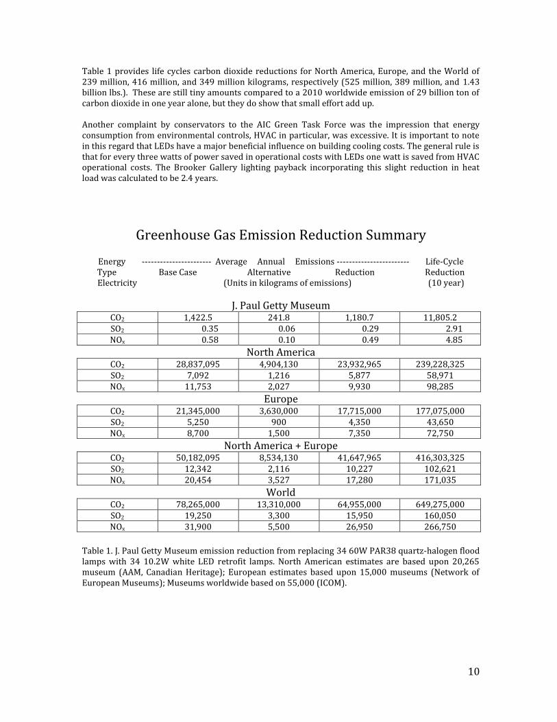
Luminous efficacy characterizes the ratio of visible light produced per watt of electrical power consumed for a given light source in lumens. A lumen being the basic photometric unit of light linked to human visual perception. Table 2 presents a few common light sources. Incandescent light sources produce low levels of visible light per watt because heat produces radiant energy over a very wide range of wavelengths that bracket our visual range.
Description Lamp Lumen Efficacy (lm/W)
Candle 0.3 60 W tungsten incandescent 5-14
Tungsten halogen 15-26 Compact fluorescent (9-26W) 35-70
White LED 30-150 T8 fluorescent, electronic ballast 80-100
Table 2. Luminous efficacy of several light sources This is a fundamental penalty paid by all blackbody radiators that create photons through heat alone. An ideal blackbody radiator at 4000K has an upper limit of 48 lumens per watt. Contrast this with the theoretical upper limit of white light if it could be created by a perfectly efficient mechanism that renders all radiant power in the visible range - about 500 lumens per watt. For a 3000-4000K light source, the difference is largely waste heat. At present, most white LEDs operate at the lower end of their efficacy range but the expectation is that it will go much higher in the future and their high performance over incandescent sources means they consume less energy for their light output and meet much stricter government energy standards.
Life span and Lumen Maintenance
Lamp Type Average Lifetime
(h x 103)
CCT (K) Lumens/watt
Tungsten bulb 0.75-1.5 2800 5-14 Tungsten halogen 2-2.5 3000 15-26
CFL bulb 6-12 2800 35-70 White LED 50* 2700,3000 30-150
Table 3. Comparison of typical light sources.
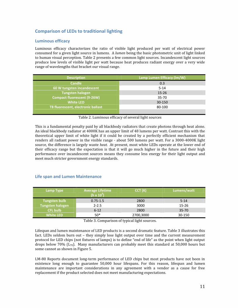
Lifespan and lumen maintenance of LED products is a second dramatic feature. Table 3 illustrates this fact. LEDs seldom burn out – they simply lose light output over time and the current measurement protocol for LED chips (not fixtures of lamps) is to define “end of life” as the point when light output drops below 70% (L70). Many manufacturers can probably meet this standard at 50,000 hours but some cannot as shown in Figure 5.
LM-80 Reports document long-term performance of LED chips but most products have not been in existence long enough to guarantee 50,000 hour lifespans. For this reason, lifespan and lumen maintenance are important considerations in any agreement with a vendor as a cause for free replacement if the product selected does not meet manufacturing expectations.
12
A closely related concept is that of luminous output. Initially, white LEDs had a very low lumen rating, often as low as 50 lumens. For a LED MR16 to match a low wattage halogen MR16 in a gallery with a 12-foot ceiling, an output of 300 is more reasonable. PAR38s need to be much higher, closer to 500-1000 lumens. For ceilings up to 40 feet or higher – 2000 lumens would be minimally needed. It is important to keep the geometry of the gallery in mind, as well as the likely display contents, when considering LED replacements. A gallery intended only for Old Master drawings will find itself severely under-illuminated if the curator decides to show paintings or dark bronzes in the same space at some point in the future. Fortunately, a range of luminous outputs are often available in the same LED lamp types.
Figure 5. Cumulated operating time (hours) – Logarithmic Scale (Source: DOE Caliper Program, http://www1.eere.energy.gov/buildings/ssl/caliper.html)
Correspondent properties
Existing incandescent lamps often encountered in museums range from high intensity low voltage pin spots (4 degrees) to wide flood lamps (50 degrees) and from 20W MR16 to 250 W PAR38 lamps. LED replacement lamps can be found for most halogen lamp types in lower wattages. However, 100W to 250W lamps cannot yet be replaced with LEDs, but can sometimes be replaced with metal halide lamps (Rosenfeld, 2011). Replacement lamp with beam angles at the extremes used at the Smithsonian American Art Museum and the Renwick Gallery (4 and 54 degrees) were initially difficult to find but have since been made available (Brodrick 2011). The main caveat is that, speaking generally, not all of the available lamps have been tested to fully meet the aesthetic, conservation, and durability requirements of an art museum.
Some properties that a lighting engineer may want to know when establishing corresponding capabilities between a lamp currently used and a possible replacement LED are center beam candle
13
power, beam angle, intensity distribution and illuminance plots, and other electrical characteristics. These will not be described in this section but can be found in IES LM-79 reports described later in these Guidelines. URLs to find and down load many of these reports are shown in the section on Internet resources. Others are available directly from the manufacturer.
LEDs often deliver more glare than the lamps they replace. Two options are to use lamps with integrated “filament” shields like the Cree LRP38 or Optiled Radar series, or specify the inclusion of an external cutoff “snoot”. These lamps are retrofits so most of the time they can be used along with a flexible set of accessories such as asymmetric lenses, spread lenses, diffusion filters, baffles, and window screens (to cut intensity when needed). These tools will come in handy because some LEDs project a more even light pattern but a few do not (Rosenfeld, 2011).
Two differences between incandescent lamps and LEDs are (1) while incandescent lamps drop in color temperature as they are dimmed, LEDs generally do not change color, and (2) LEDs unlike almost every other light source is “instant on”. The comment that LEDs do not change color when dimmed is always true for the type of dimming called Pulse Width Modulation (PWM). If the forward current through the chip is kept constant and only the duty cycle, or period the current is actually turned on, is varied, color remains constant for all types of chips. If the on-off cycle exceeds 120 Hz (above 300 Hz is often recommended), the human visual system is unable to detect any flicker, yet the eye still integrates intensity over time. This effectively dims apparent brightness. The percent of time the chips are “on” is linearly related to brightness. The second major method for dimming is to lower the current and LEDs do not change color when this is done except for the most important chip design in use with white phosphor LEDs – Indium Gallium Arsenide LEDs – InGaN. In one way this is a benefit since the bright blue InGaN chips can also be made to produce two new high intensity colors, verde and true green (Ott, Plotz et al. 2003). It has been reported that some white LEDs may appear bluer when dimmed (DOE 2011). The J. Paul Getty Museum tends to avoid all these issues by employing screens to hit their target illumination levels.
Color Rendering Index (CRI)
The Color Rendering Index, widely used within the lighting industry since 1965, is a metric that is sometimes misunderstood to represent “color rendering quality” in some absolute way. In fact, CRI has little to do with color quality, and at high or low values of correlated color temperature a CRI of 100 will be calculated when actual color fidelity or naturalness in appearance is questionable. It is also based on a outdated uniform color space. The red region is particularly non-uniform (Davis and Ohno 2005). For this and other reasons at least two other color metrics have been proposed recently to replace it (Ohno and Davis; Rea and Freyssinier-Nova, 2008). The CRI rather is a color matching metric that uses a set of 8 Munsell color swatches to estimate how closely a test light source will be to a reference source in color matching. For a test light source with color characteristics that place it on the blackbody locus (See “Color consistency” below and Figures 6 & 7) at 3000K, the CRI is computed against a theoretical blackbody at 3000K regardless of how good or how bad that reference source actually renders a specific color in the eyes of the beholder. The CRI has been adjusted to render a value of 100 if the color match of the Munsell reference color swatches is perfect between test and reference light sources. It is generally agreed that a CRI above 85 is suitable for display purposes. Many early LED products failed to achieve this target and often rendered some high chroma (i.e. highly saturated) colors dismally. Today the best quality white LEDs routinely measure above 90 and often above 95 when evaluated against a 3000K incandescent reference source. But direct visual comparisons are informative. During assessment of several lamps at the Jordan Schnitzer Museum of Art in Eugene, Oregon in late 2010, observers appreciated how the LED lamps improved their ability to see blue colors, but their preferences did not correspond well to CRI. Two LEDs with CRI values of 93 and 85 were preferred to halogen lamps at 99. In addition, the artist, Chris Jordan whose works was going to be shown in January 2011 noted that, unlike the halogen lamps, there were no color shifts in his daylight, color balanced, works.
14
Because LEDs, like fluorescent lamps, are not blackbodies that generate light with heat it is not strictly accurate to classify them by a blackbody color temperature. For this purpose Correlated Color Temperature is used to make this distinction. High CRI white LEDs often fall closer to the blackbody locus for a given CCT than some dichroic halogen lamps. There are many reasons one might wish to have high CRI LED replacement illumination in galleries. But not all locations and lighting requirements in museums and archives necessarily demand it. Facilities managers can easily get by in food services areas, elevators, office spaces, machine shops, exterior walkways, general down lighting, cove accent lighting, and HVAC service areas using LEDs that meet less rigorous standards in CRI, luminous efficiency, or luminous output. A particular type of lamp may only be available in one format and for these less critical areas they would serve perfectly well. Furthermore, since CRI is not necessarily a reliable metric for color preference, the curator’s eye may find lower CRI LED products to be superior for their use in different circumstances. The Shelburne Museum completed an LED retrofit assessment employing MR16, PAR20 and PAR30 lamps manufactured by Sylvania and Philips, predicating their selection solely on aesthetics. The CRI metric was a secondary consideration. They settled on lamps with a CRI in the mid-80s. Appendix 1 displays a series of color swatches in both the CRI and the CQS method.
Color consistency and appearance over time
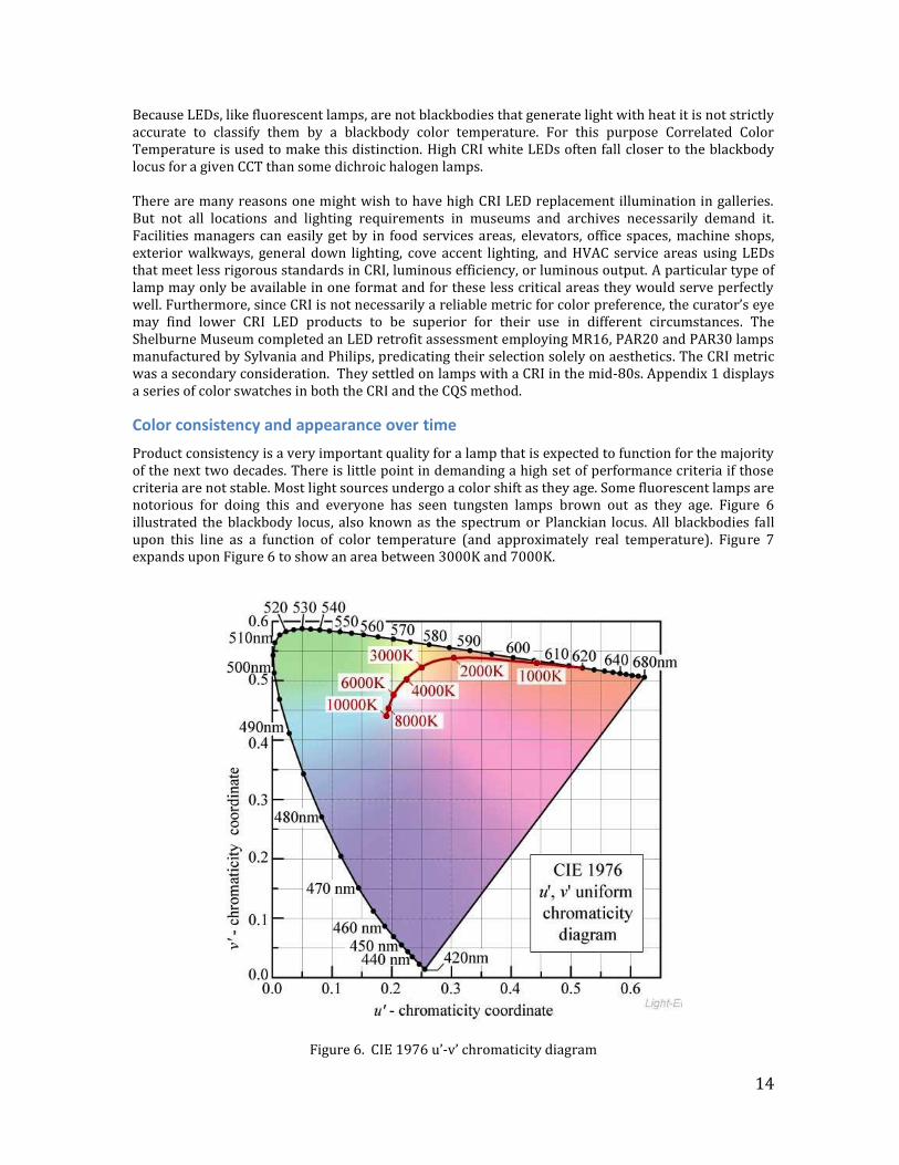
Product consistency is a very important quality for a lamp that is expected to function for the majority of the next two decades. There is little point in demanding a high set of performance criteria if those criteria are not stable. Most light sources undergo a color shift as they age. Some fluorescent lamps are notorious for doing this and everyone has seen tungsten lamps brown out as they age. Figure 6 illustrated the blackbody locus, also known as the spectrum or Planckian locus. All blackbodies fall upon this line as a function of color temperature (and approximately real temperature). Figure 7 expands upon Figure 6 to show an area between 3000K and 7000K.
Figure 6. CIE 1976 u’-v’ chromaticity diagram
15
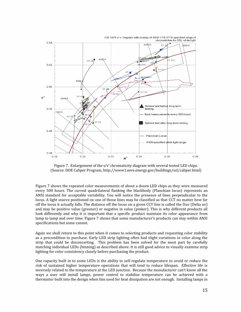
Figure 7. Enlargement of the u’v’ chromaticity diagram with several tested LED chips.
(Source: DOE Caliper Program, http://www1.eere.energy.gov/buildings/ssl/caliper.html)
Figure 7 shows the repeated color measurements of about a dozen LED chips as they were measured every 500 hours. The curved quadrilateral flanking the blackbody (Planckian locus) represents an ANSI standard for acceptable variability. You will notice the presence of lines perpendicular to the locus. A light source positioned on one of those lines may be classified as that CCT no matter how far off the locus it actually falls. The distance off the locus on a given CCT line is called the Duv (Delta uv) and may be positive value (greener) or negative in value (pinker). This is why different products all look differently and why it is important that a specific product maintain its color appearance from lamp to lamp and over time. Figure 7 shows that some manufacturer’s products can stay within ANSI specifications but some cannot.
Again we shall return to this point when it comes to selecting products and requesting color stability as a precondition to purchase. Early LED strip lighting often had slight variations in color along the strip that could be disconcerting. This problem has been solved for the most part by carefully matching individual LEDs (binning) as described above. It is still good advice to visually examine strip lighting for color consistency closely before purchasing the product. One capacity built in to some LEDs is the ability to self-regulate temperature to avoid or reduce the risk of sustained higher temperature operations that will tend to reduce lifespan. Effective life is inversely related to the temperature at the LED junction. Because the manufacturer can’t know all the ways a user will install lamps, power control to stabilize temperature can be achieved with a thermistor built into the design when fins used for heat dissipation are not enough. Installing lamps in
16
down lights with poor ventilation and high insulation are examples of these conditions. The Smithsonian American Art Museum tracked lux fall-off on a series of paintings with one example on a Marsden Hartley painting falling from an initial value of 160 lux illumination to 120 lux after two hours and rising back to 140 lux in another hour and remaining at that value the rest of the day. It is unlikely that these kind of fluctuations will be large enough in most cases to cause a problem or be noticed by the visitors.
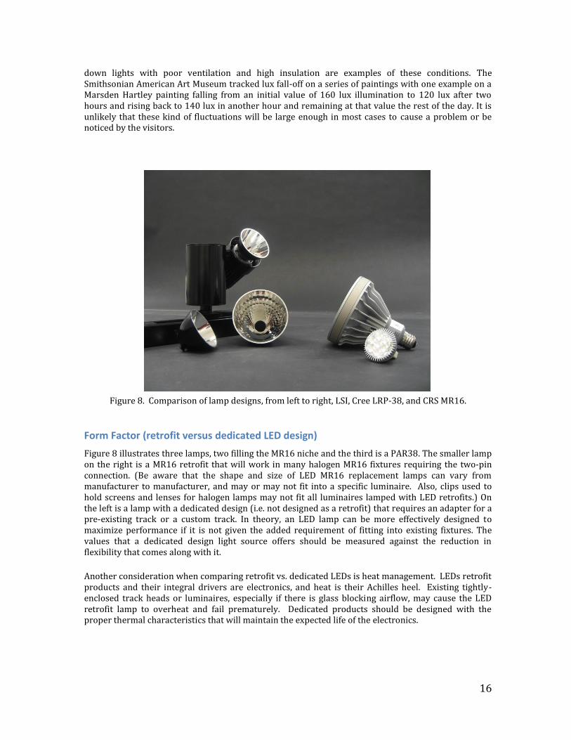
Figure 8. Comparison of lamp designs, from left to right, LSI, Cree LRP-38, and CRS MR16.
Form Factor (retrofit versus dedicated LED design)
Figure 8 illustrates three lamps, two filling the MR16 niche and the third is a PAR38. The smaller lamp on the right is a MR16 retrofit that will work in many halogen MR16 fixtures requiring the two-pin connection. (Be aware that the shape and size of LED MR16 replacement lamps can vary from manufacturer to manufacturer, and may or may not fit into a specific luminaire. Also, clips used to hold screens and lenses for halogen lamps may not fit all luminaires lamped with LED retrofits.) On the left is a lamp with a dedicated design (i.e. not designed as a retrofit) that requires an adapter for a pre-existing track or a custom track. In theory, an LED lamp can be more effectively designed to maximize performance if it is not given the added requirement of fitting into existing fixtures. The values that a dedicated design light source offers should be measured against the reduction in flexibility that comes along with it.
Another consideration when comparing retrofit vs. dedicated LEDs is heat management. LEDs retrofit products and their integral drivers are electronics, and heat is their Achilles heel. Existing tightly-enclosed track heads or luminaires, especially if there is glass blocking airflow, may cause the LED retrofit lamp to overheat and fail prematurely. Dedicated products should be designed with the proper thermal characteristics that will maintain the expected life of the electronics.
17
Cost and ROI Payback
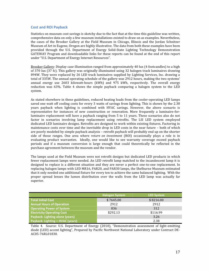
Statistics on museum cost savings is sketchy due to the fact that at the time this guideline was written, comprehensive data on only a few museum installations existed to draw on as examples. Nevertheless, the cases of the Brooker Gallery at the Field Museum in Chicago, Illinois and the Jordan Schnitzer Museum of Art in Eugene, Oregon are highly illustrative. The data from both these examples have been provided through the U.S. Department of Energy Solid-State Lighting Technology Demonstration GATEWAY Program and downloadable links for these reports can be found at the end of this report under “U.S. Department of Energy Internet Resources”. Brooker Gallery: Display case illumination ranged from approximately 40 lux (4 footcandles) to a high of 370 lux (37 fc). This gallery was originally illuminated using 32 halogen track luminaires drawing 894W. They were replaced by 26 LED track luminaires supplied by Lighting Services, Inc. drawing a total of 335W. The annual operating schedule of the gallery was 2912 hours, making the two systems’ annual energy use 2603 kilowatt-hours (kWh) and 975 kWh, respectively. The overall energy reduction was 63%. Table 4 shows the simple payback comparing a halogen system to the LED system.
As stated elsewhere in these guidelines, reduced heating loads from the cooler-operating LED lamps saved one watt off cooling costs for every 3 watts of savings from lighting. This is shown by the 2.38 years payback when lighting is combined with HVAC savings. However, the above scenario is representative for instances of new construction or renovation. More frequently a luminaire-for-luminaire replacement will have a payback ranging from 5 to 11 years. These scenarios also do not factor in scenarios involving lamp replacement using retrofits. The LSI LED system employed dedicated LED luminaire designs. Retrofits are designed to work within existing fixtures. Factoring in maintenance costs over time and the inevitable drop in LED costs in the near future – both of which are poorly modeled by simple payback analysis – retrofit payback will probably end up on the shorter side of those ranges. One area where return on investment (ROI) occasionally plays a role is in evaluating product warranties. Ideally, one would like to see warranty coverage exceed payback periods and if a museum conversion is large enough that could theoretically be reflected in the purchase agreement between the museum and the vendor.
The lamps used at the Field Museum were not retrofit designs but dedicated LED products in which fewer replacement lamps were needed. An LED retrofit lamp matched to the incandescent lamp it is designed to replace is a different situation and they are never a perfect one-to-one replacement. In replacing halogen lamps with LED MR16, PAR20, and PAR30 lamps, the Shelburne Museum estimated that it only needed one additional fixture for every ten to achieve the same balanced lighting. With the proper spread lenses the lumen distribution over the walls from the LED lamp was actually far superior.
Halogen System LED System
Total Initial Cost $ 7645.00 $ 8216.00 Annual Hours of Operation 2912 2912 Operating Power of System 836 312 Electricity Operating Cost $292.13 $116.99 Payback: Lighting alone (years) 3.26 Payback: Lighting + HVAC (years) 2.38
Table 4. Source: U.S. Department of Energy (2010), “Demonstration assessment of light-emitting diode (LED) accent lighting”, Prepared by Pacific Northwest National Laboratory under Contract DE-AC05-76RL01830.
18
One factor that was experienced during the Field Museum installation, reported to be common with systems involving LEDs, is that as the LEDs were dimmed by the control system, the illuminance decreased but the measured current did not. This means that although the LED save significant energy, any further savings from dimming may be small. Jordan Schnitzer Museum of Art: In this example, gallery lighting ranged from a high of 198 lux (18.4 footcandles) on paintings to as low as 11 lux (1.0 footcandle) between them. Illumination had been provided by track lighting using 49 tungsten-halogen Sylvania 90W PAR38 130V Narrow Flood (25°) lamps that drew 78.9W at 120V for an average life of 5,000 hours. The period of use was 2548 hours per year consuming 9850 kWh. These were replaced with 54 Cree PAR38 LED 12W lamps having an average life of 50,000 hours. Therefore the Sylvania lamps had an expected life of 2 years at $5.42 per lamp, and the Cree lamps of 20 years at $108 per lamp. The electrical use for the LEDs was calculated to be 1403 kWh or only 14% of the energy consumed by the halogen units with a life 10 times longer. There are two reasons to pursue a lighting conversion as described here. The first is to save electrical costs and the labor associated with lamp replacement. The second is to achieve energy sustainability goals, which aligns with a museum’s strategic goals for preserving heritage and the environment. Because the cost of electricity is lower in Oregon than the national average ($0.06/kWh versus $0.10/kWh) simple payback will be longer at 9 years. For the national average it would shorten to 6 years and for rates of $0.15/kWh (Southern California) 4 years. Payback in Hawaii would be even more dramatic with the rate to the University of Hawaii at Manoa (Oahu) being approximately $0.25/kWh. Reduction in carbon dioxide, sulfur dioxide and oxides of nitrogen follow a similar percent reduction as electricity: CO2 dropping from an annual emission of 1927 kg to 275 kg.
Mature versus evolving technologies
One often hears that the reason for not adopting some technology, especially if it is expensive or contains a high resource barrier, is that the technology may be so new that if one waits, a better variant will surely appear on the horizon very soon. This excuse for inaction ignores the reality that what we call “a technology” is actually a large set of product development cycles that began at different times, will mature at different rates, and demonstrate different degrees of product durability in the marketplace. White phosphor LEDs are a rapidly maturing subset of products that have among their members, excellent products that when well-matched to their application should not need replacement. But apart from how well individual products fill a given need there are still industry-wide fragmentations. All groups benefit when incompatibilities between manufacturers are reduced or eliminated, or when existing functionalities are expanded to new groups of users. This reduces fragmentation and increases consumer confidence. We’ll show examples of this in three areas. Dimmer incompatibilities with LEDs resulting in flicker (see “Dimming and Flicker” below), better hardware interchangeability, and the wider use of wireless personal area networks. Hardware interchangeability is currently being addressed by the Zhaga Consortium. Zhaga is seeking to create standards for LED sources that would make mechanical and thermal fit with heat sinks, specifying the size and height of the emitting surfaces, and standardizing photometric properties, for specific applications of products. This would allow manufacturers of luminaires greater freedom in selecting light engines but leave the interfaces between LED module and electronic control (driver) untouched. If successful, the Zhaga compliant standards would also “future-proof” light engines (LED module + driver) which can then be second sourced and upgraded in the future. Another example illustrates how the control of individual luminaires is being extended to more users including museums. DMX512-A has long been a standard in lighting control consoles for stage lighting, studio lighting, and theme park attractions. ZigBee is a specification for a communication protocol based upon small, low-power digital radios. It is simpler and less expensive than other wireless personal area networks like Bluetooth when low data rates suffice. Coupled with compatible dimming,
19
ZigBee could allow lighting designers and conservators far greater flexibility and ease in adjusting to minimize exposure dose for light-sensitive artifacts while including a facile method to provide controlled intensity modulation for older visitors and/or difficult visual tasks – all from the floor with a hand-held device. Such control is not generally available now but should be in the near future.
Controlling Glare
One remark that has occasionally been raised is that LEDs seem to introduce more potential for problems with glare. All lighting produces the potential for glare. But with solid-state lighting part of the solution comes from selecting lamps that minimize glare and part is in thoughtful lighting design. Direct glare is caused by high contrast between the lighting source and the background. When the source is especially small, like an LED, the glare potential is increased. The best method to decrease glare is to install a "cutoff" that shields the viewer from the light source. A 45-degree cutoff is ideal. The cutoff can take any number of shapes from a shallow hex-cell louver, to a simple snoot (tube). For most museum applications the cutoff should be painted matte black. It is inherently difficult to produce a wide beam light that is low glare. A common solution in museums is to use narrower beam lamps (25-35 degrees) and install them at regular intervals (every 3-6 feet depending on the ceiling height). Another method is to increase the surface area of the illuminant. This is a guiding principle in office design but some lighting designers feel that for museums this may be a flawed strategy. In museums you might find that spotlights are often more prone to glare because the surface area of "the bright spot" is smaller compared to floodlights - this might be counterintuitive because the spotlights produce a more collimated light.
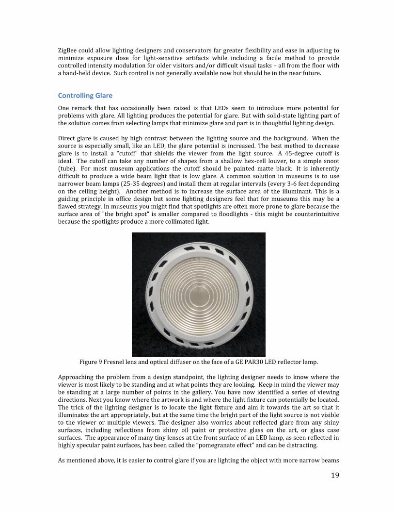
Figure 9 Fresnel lens and optical diffuser on the face of a GE PAR30 LED reflector lamp.
Approaching the problem from a design standpoint, the lighting designer needs to know where the viewer is most likely to be standing and at what points they are looking. Keep in mind the viewer may be standing at a large number of points in the gallery. You have now identified a series of viewing directions. Next you know where the artwork is and where the light fixture can potentially be located. The trick of the lighting designer is to locate the light fixture and aim it towards the art so that it illuminates the art appropriately, but at the same time the bright part of the light source is not visible to the viewer or multiple viewers. The designer also worries about reflected glare from any shiny surfaces, including reflections from shiny oil paint or protective glass on the art, or glass case surfaces. The appearance of many tiny lenses at the front surface of an LED lamp, as seen reflected in highly specular paint surfaces, has been called the “pomegranate effect” and can be distracting. As mentioned above, it is easier to control glare if you are lighting the object with more narrow beams
20
of light, because you can anticipate the reflective angles more precisely, and hence the glare locations. That is the reason why the Cree LRP38 is easy to use for display lighting: The beam is pretty accurately contained within the 20 degree beam angle because there is no exposed filament or LED that sends uncontrolled light to angles outside that 20 degree beam. That is the beauty of the halogen AR111 lamp, as well. The filament shield blocks the stray light so that all you get out of the lamp is the luminous intensity that is forced to bounce off the reflector into the intended beam angle. General Electric reduces the glare potential of their PAR30 and PAR38 lamps by locating the LEDs deep within the lamp near the Edison screw base. The reflector is a conical, specular reflector that acts as a color-mixing chamber. At the lamp face a weak optical diffuser is mounted outside of a Fresnel lens to soften the edge of the beam and to eliminate any persistent hot spots (Figure 9). General Electric produces these lamps with CRIs in the mid-80s and a “retail version” with a CRI in the mid-90s including nearly 80 for R9 (bright red) – a particularly difficult color for LEDs in general to excel at matching incandescent lamps. Glare may be in the eye of the beholder but the solution is clearly in the mind of the lighting specialist.
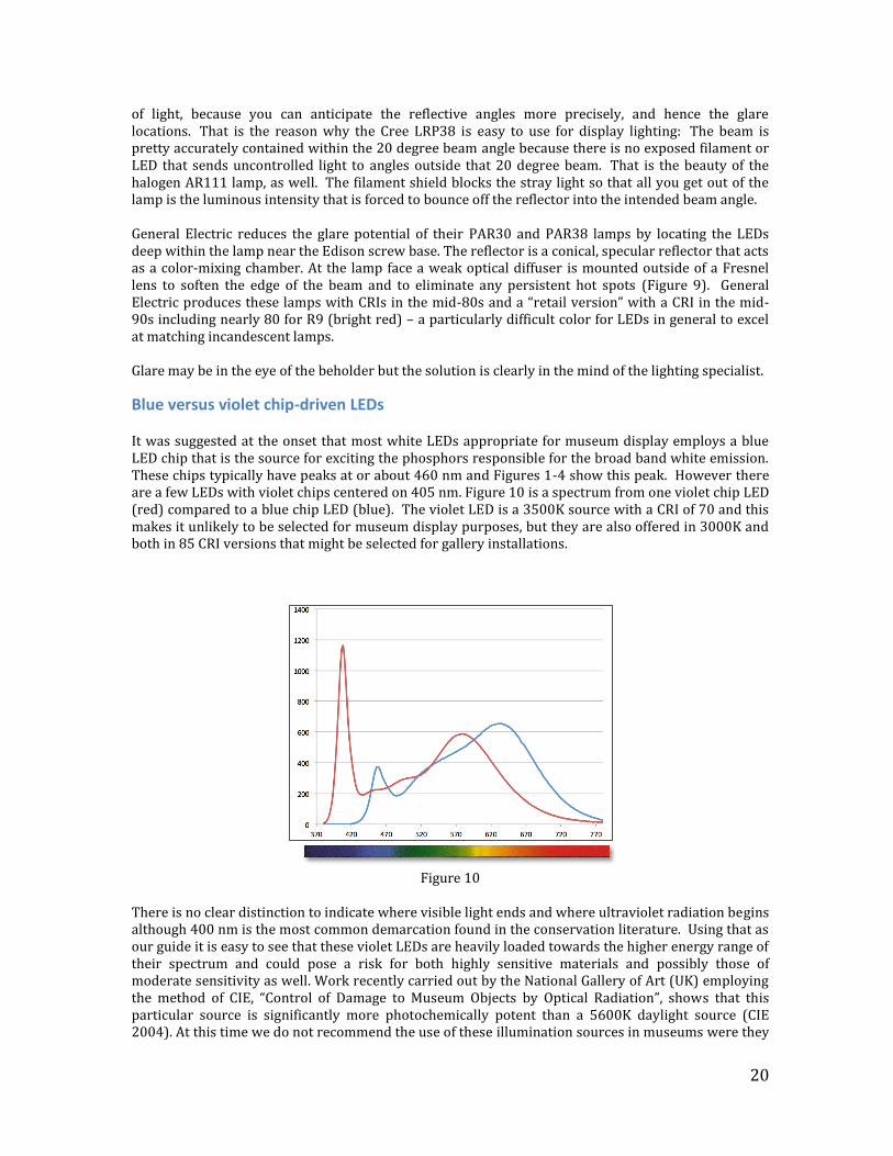
Blue versus violet chip-driven LEDs It was suggested at the onset that most white LEDs appropriate for museum display employs a blue LED chip that is the source for exciting the phosphors responsible for the broad band white emission. These chips typically have peaks at or about 460 nm and Figures 1-4 show this peak. However there are a few LEDs with violet chips centered on 405 nm. Figure 10 is a spectrum from one violet chip LED (red) compared to a blue chip LED (blue). The violet LED is a 3500K source with a CRI of 70 and this makes it unlikely to be selected for museum display purposes, but they are also offered in 3000K and both in 85 CRI versions that might be selected for gallery installations.
Figure 10
There is no clear distinction to indicate where visible light ends and where ultraviolet radiation begins although 400 nm is the most common demarcation found in the conservation literature. Using that as our guide it is easy to see that these violet LEDs are heavily loaded towards the higher energy range of their spectrum and could pose a risk for both highly sensitive materials and possibly those of moderate sensitivity as well. Work recently carried out by the National Gallery of Art (UK) employing the method of CIE, “Control of Damage to Museum Objects by Optical Radiation”, shows that this particular source is significantly more photochemically potent than a 5600K daylight source (CIE 2004). At this time we do not recommend the use of these illumination sources in museums were they
21
could be cause concern.
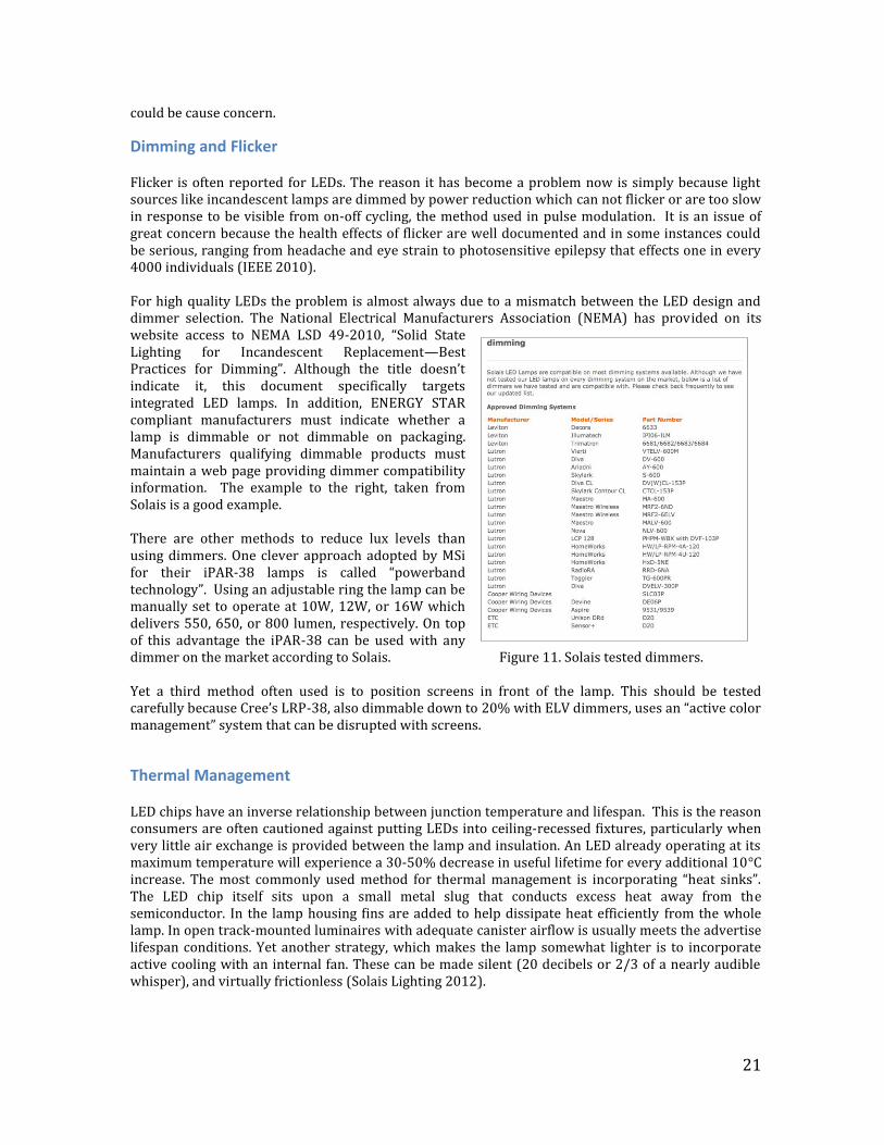
Dimming and Flicker Flicker is often reported for LEDs. The reason it has become a problem now is simply because light sources like incandescent lamps are dimmed by power reduction which can not flicker or are too slow in response to be visible from on-off cycling, the method used in pulse modulation. It is an issue of great concern because the health effects of flicker are well documented and in some instances could be serious, ranging from headache and eye strain to photosensitive epilepsy that effects one in every 4000 individuals (IEEE 2010). For high quality LEDs the problem is almost always due to a mismatch between the LED design and dimmer selection. The National Electrical Manufacturers Association (NEMA) has provided on its website access to NEMA LSD 49-2010, “Solid State Lighting for Incandescent Replacement—Best Practices for Dimming”. Although the title doesn’t indicate it, this document specifically targets integrated LED lamps. In addition, ENERGY STAR compliant manufacturers must indicate whether a lamp is dimmable or not dimmable on packaging. Manufacturers qualifying dimmable products must maintain a web page providing dimmer compatibility information. The example to the right, taken from Solais is a good example. There are other methods to reduce lux levels than using dimmers. One clever approach adopted by MSi for their iPAR-38 lamps is called “powerband technology”. Using an adjustable ring the lamp can be manually set to operate at 10W, 12W, or 16W which delivers 550, 650, or 800 lumen, respectively. On top of this advantage the iPAR-38 can be used with any dimmer on the market according to Solais. Figure 11. Solais tested dimmers. Yet a third method often used is to position screens in front of the lamp. This should be tested carefully because Cree’s LRP-38, also dimmable down to 20% with ELV dimmers, uses an “active color management” system that can be disrupted with screens.
Thermal Management LED chips have an inverse relationship between junction temperature and lifespan. This is the reason consumers are often cautioned against putting LEDs into ceiling-recessed fixtures, particularly when very little air exchange is provided between the lamp and insulation. An LED already operating at its maximum temperature will experience a 30-50% decrease in useful lifetime for every additional 10°C increase. The most commonly used method for thermal management is incorporating “heat sinks”. The LED chip itself sits upon a small metal slug that conducts excess heat away from the semiconductor. In the lamp housing fins are added to help dissipate heat efficiently from the whole lamp. In open track-mounted luminaires with adequate canister airflow is usually meets the advertise lifespan conditions. Yet another strategy, which makes the lamp somewhat lighter is to incorporate active cooling with an internal fan. These can be made silent (20 decibels or 2/3 of a nearly audible whisper), and virtually frictionless (Solais Lighting 2012).
22
Replacing T12 Fluorescent Lamps Occasionally, display lighting can entail fluorescent lamps, and the replacement of T12 tubes (1.5 inches in diameter) may be necessary due to reasons including failing and difficult-to-find replacement hardware and a popular concern for avoiding mercury in lighting products. Sylvania Commercial Grade and Philips EnduraLED T8 (1.0 inches in diameter) are two, but not the only, effective replacement lines of products available. Yet, while the energy savings are advertised in the 30-40% range, given the individual lamp prices ($50-$100 each) they may not be as compelling as the replacement of incandescent light sources in all situations. The overall cost savings may be difficult to realize. But, their lifespans are significantly longer and they incorporate improved performance such as no warm-up, instant-on status at full light output and stable lamp color. LED fluorescent can have color rendering values in the mid- to high 80s, at correlated color temperatures of 2700K, 3000K, 3500K, 4100K and 5000K, in both 2 and 4 foot lengths. Lastly, the lack of ultraviolet radiation is a more important consideration in fluorescent LED replacements than for incandescent lamps. The biggest difference in labor between fluorescent lamps and incandescent ones is that for the former it becomes a replacement, the latter is a true retrofit. You cannot just twist in LEDs for fluorescent lamps. Their installation requires a professional electrician. The ballast needs to be disconnected, shunted G13 medium bi-pin lamp holders must be replaced with non-shunted versions and the fixtures wired directly for 120V or 277V. Installation guides are readily accessible.
LED Decision-Making In a Nutshell LED lighting that use a blue chip contains no ultraviolet and little infrared. They are warm to the
touch in spite of some industry claims that they produce no heat so consider carefully how they might be used inside enclosures.
Avoid white LED that employ a violet chip to drive the phosphor as they overlap into the near
ultraviolet region.
To save the most energy (and reduce cost of operation), insist on high luminous efficacy. 40 lumens/watt is a good starting point. Lower than this, cost savings will be marginal.
To illuminate areas with a more utilitarian such as machinery, many science exhibits, food
services, hallways, educational activities, etc. settle on a color rendering index (CRI) above 80.When color matching may be more an attentive activity such as viewing art, ethnography, some natural history collections exhibits, etc. select LEDs with a CRI above 90. However, because CRI is an imperfect metric, CRI should be considered a target, not a firm criterion.
If you wish to replace tungsten, tungsten halogen, or an equivalent fluorescent lighting and you
prefer your lighting a little warmer, select a color temperature between 2700K and 2800K; for preferences a little cooler or “whiter,” pick 3000K. Generally avoid higher color temperatures for light sensitive materials as these LEDs may have an unacceptably large peak in the “blue region” of the spectrum.
Be cautious of color temperature and CRI claims because lamp-to-lamp consistency may not be
adequate. Agree with vendor on your right to have replacements lamps supplied when consistency is inadequate out-of-the-box or a lamp changes color during operation.
Ask your facilities manager to acquire and review LM-79 reports from lamp manufacturers. Have
him/her look for a positive Duv specification greater than 0.006. These lamps may introduce a greenish appearance and should perhaps best be avoided.
23
Look for any GATEWAY project reports from the U.S. Department of Energy (DOE) that describes a solid-state re-lamping project in an art museum. Contact that institution and ask for their recommendations. Visit them if possible.
Once you have made preliminary decisions on several candidate lamps look at all of them
yourself.
o Check color rendering on your own skin o Try dimming it with recommended dimmer and specified transformer o Check for flicker in undimmed and dimmed state. o LED strip lighting should be dimmable to provide a high level of control in compact space.
Dimming may extend lamp life but flicker could be a problem. Check this carefully. Most large, brand-named lighting companies supply high quality products but they also supply
poor ones. Make no assumptions of quality based on brand alone. Many smaller companies are motivated to provide good support.
Don’t compromise too easily if a given manufacturer does not have the right lamp for you (beam
angle, lumens, type of lamp). There are many good products in the marketplace that cover a range of uses and another manufacturer’s products may fit your need better. You can expect to find many MR16, PAR30, PAR38 and A-lamps offered.
Retrofit lamps are easiest to install in existing tracks and fixtures. But don’t discount lamps with a
dedicated or unique design and shape. Some of these only require an adapter to fit an older track or one from another manufacturer.
If you are going to be dimming your LEDs confirm that the method of dimming is compatible with
the LED chip and driver used. No LED will change color upon dimming when the technique used is pulse width modulation (PWM), but some PWM techniques can introduce flicker. White phosphor LEDs may change color if dimming is accomplished in the same manner as with incandescent lighting – reducing the line voltage.
Know what your product warranty covers. A one-year warranty is common but for longer periods
of time coverage may be limited to a catastrophic failure of the LED chip. Failure of ballasts and drivers may not be covered at all. Consider the return on investment payback (ROI) period. You may be satisfied if ROI payback is less than the warranty period. Warranties exist that cover major failure, significant loss of luminosity and any visible change in color temperature for up to 25,000 hours.
SECTION 2: Making the Decision: Which LEDs Products to Buy
REVIEW
Ever increasingly, museum, library and archives are being asked to consider steps that will reduce their energy needs. Sometimes the motivation is simply budgetary but often it is linked to larger pressures to reduce the overall institutional carbon footprint. Nowhere is this more visible than institutions operated by universities, government agencies, or in regions where new laws have been passed mandating such changes by a specified date. One area of focus is in lighting. Conservators, registrars, and curators are being asked to consider whether or not lighting can be switched to LEDs. White phosphor LEDs can be used in cultural institutions for virtually any purpose but the requirements will vary between areas with different functions. Sources used for display lighting in art galleries will tend to have color rendering index values higher than 90 and CCTs between 2700K and 3000K. This makes the
24
transition as inconspicuous as possible as LEDs replace incandescent lighting. Given the costs of a solid-state lighting switchover, galleries may be phased in on a schedule and one may wish to reduce the differences in appearance of adjacent spaces.
Since one application might be to augment general gallery illumination from existing skylights when the daylight contribution is low, the color targets may be relaxed to employ lamps with higher correlated color (such as 4000K to 6000K), closer to some form of daylight.
Keep in mind that color metrics do not always match human perception and should be considered guidelines rather than rigid criteria. Sometimes the displayed objects look better under a lower-CRI lamp. And museum staff interviews suggest that a lower CRI is difficult to quantify particularly in the absence of highly chromatic (strong hues) colors. The Brooker Gallery at the Field Museum in Chicago (See Cost Payback) converted to 80 CRI LEDs rather than use LEDs with CRIs near 95. The museum staff was split on the question of how accurate the subject colors were rendered, with 11 responding that “some” colors were accurate and 14 responding that “most” or “all” were accurate. This type of statistical distribution is very common and may indicate nothing more than a random scatter of preferences that could have occurred even with a higher CRI light source. The Shelburne Museum also settled on LEDs with a CRI in the mid-80s based solely on the curatorial judgment of how well the objects looked in a historical house setting.
READ
After you have reviewed your own requirements for establishing a solid-state lighting effort in your institution, whatever the proximal motivation, you’ll wish to review some of the powerful resources available from various government agencies on the Internet. One of the most extensive sets of resources in North America is the U.S. Department of Energy (DOE) solid-state lighting program. This program is broad in scope: Development of product standards and specification Product testing (CALiPER) Development of fact sheets, product labeling, and educational materials Product design competitions GATEWAY demonstrations
We will not describe these resources in detail. Many of them are more appropriately used to assist designers and other consultants in making thoughtful decisions for clients. We will briefly list their values.
Product Testing (CALiPER)
Solid-state lighting (SSL) technologies today are changing and improving rapidly, and products arriving on the market exhibit a wide range of performance. There is a need for reliable, unbiased product performance information to foster the developing market for high-performance SSL products. The DOE Commercially Available LED Product Evaluation and Reporting (CALiPER) program supports testing of a wide array of SSL products available for general illumination. DOE allows its test results to be distributed in the public interest for non-commercial, educational purposes only. Detailed test reports are provided to users who provide their name, affiliation, and confirmation of agreement to abide by DOE's NO COMMERCIAL USE POLICY.
IES LM-79
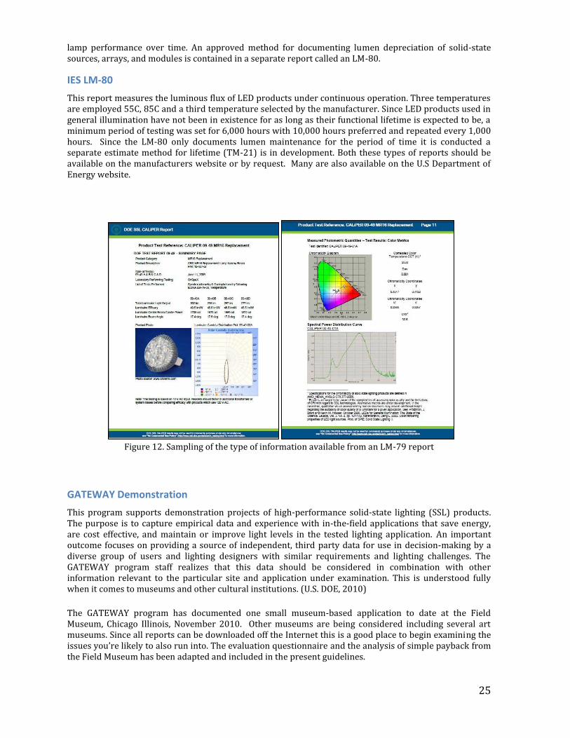
These reports comply with standards of measurement in conformance with the Illuminating Engineering Society of North America (IESNA) and are directed toward LED-based products incorporating control electronics and heat sinks. Most lamps, since they are integrated sources, are covered under these procedures. These are independent laboratory measurements of total flux, electrical power, efficacy and chromaticity. Figure 12 illustrates this data in an MR16 retrofit lamp. The LM-79 report does not cover
25
lamp performance over time. An approved method for documenting lumen depreciation of solid-state sources, arrays, and modules is contained in a separate report called an LM-80.
IES LM-80
This report measures the luminous flux of LED products under continuous operation. Three temperatures are employed 55C, 85C and a third temperature selected by the manufacturer. Since LED products used in general illumination have not been in existence for as long as their functional lifetime is expected to be, a minimum period of testing was set for 6,000 hours with 10,000 hours preferred and repeated every 1,000 hours. Since the LM-80 only documents lumen maintenance for the period of time it is conducted a separate estimate method for lifetime (TM-21) is in development. Both these types of reports should be available on the manufacturers website or by request. Many are also available on the U.S Department of Energy website.
Figure 12. Sampling of the type of information available from an LM-79 report
GATEWAY Demonstration
This program supports demonstration projects of high-performance solid-state lighting (SSL) products. The purpose is to capture empirical data and experience with in-the-field applications that save energy, are cost effective, and maintain or improve light levels in the tested lighting application. An important outcome focuses on providing a source of independent, third party data for use in decision-making by a diverse group of users and lighting designers with similar requirements and lighting challenges. The GATEWAY program staff realizes that this data should be considered in combination with other information relevant to the particular site and application under examination. This is understood fully when it comes to museums and other cultural institutions. (U.S. DOE, 2010)
The GATEWAY program has documented one small museum-based application to date at the Field Museum, Chicago Illinois, November 2010. Other museums are being considered including several art museums. Since all reports can be downloaded off the Internet this is a good place to begin examining the issues you’re likely to also run into. The evaluation questionnaire and the analysis of simple payback from the Field Museum has been adapted and included in the present guidelines.
26
ENERGY STAR ENERGY STAR is a U.S. government-backed program providing the consumer with the assurance that products are energy efficient and will reduce greenhouse gas emissions and other pollutants. For lighting the criteria to use the ENERGY STAR label goes far beyond. Program requirements for integrated LED lamps (all lighting described in this report) include the specified ANSI, CIE, IESNA, and UL standards, guides and methods applicable to the rating. These encompass four correlated color temperatures, their tolerances and target Duv; color maintenance to the first 6,000 hours of operations; minimum color rendering index and R9 value; dimming; warranty; LED operating frequency; and a number of power-related factors. For directional lamps — BR, ER, K, MR, PAR, R — it also specifies a minimum luminous efficacy and lumen maintenance. For LED uses as decorative elements in historic structures, product life rating for ENERY STAR differs from directional display lighting. For the latter it is L70 or when 50% of the lamps light output drops to 70% of the initial intensity at 25,000 hours. For decorative lamps the life rating for L70 is set at 15,000 hours. This is a minimum criterion.
Lighting Facts Labels
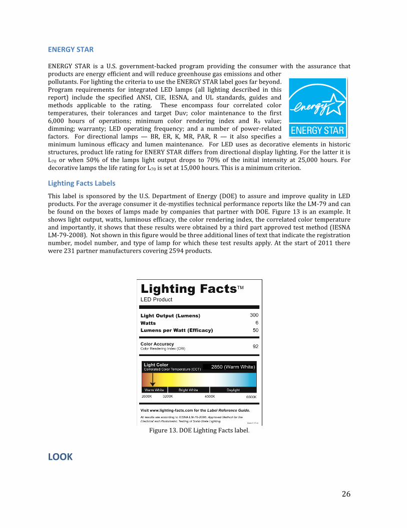
This label is sponsored by the U.S. Department of Energy (DOE) to assure and improve quality in LED products. For the average consumer it de-mystifies technical performance reports like the LM-79 and can be found on the boxes of lamps made by companies that partner with DOE. Figure 13 is an example. It shows light output, watts, luminous efficacy, the color rendering index, the correlated color temperature and importantly, it shows that these results were obtained by a third part approved test method (IESNA LM-79-2008). Not shown in this figure would be three additional lines of text that indicate the registration number, model number, and type of lamp for which these test results apply. At the start of 2011 there were 231 partner manufacturers covering 2594 products.
Figure 13. DOE Lighting Facts label.
LOOK
27
A visual assessment should be carried out using the type of objects that would be illuminated under accurate exhibition conditions including the lux levels that would be anticipated. Constant levels of illumination are important because higher illuminance can shift the perception of hue (Bezold-Brucke effect), and different spectra for two light sources with the same chromaticity can influence the perception of brightness (Helmholtz-Kolrausch effect). An example of why lighting design is important is provided by Boyce describing one of the few examples in the literature directly pertinent to museum display. Mangum carried out an assessment of a doll dressed in materials that varied in color, texture and reflective properties at 50 lux. Observers were asked to report their perceptions of the object selecting descriptors from either a word list of positive impressions or a word list of negative ones. When the lighting was diffuse, the most frequent responses included “unattractive, unpleasant, obscured, veiled, bland, boring, mundane and ordinary”. When the lighting used key-light, side-light, or back-light techniques, conditions that changed higher order perceptions, the descriptions shifted to “interesting, attractive, eye-catching, clear, pleasant, revealing, dramatic, and spectacular”(Mangum 1998). Boyce further informs us that for simple perceptions the greatest perceptual stability when making these kinds of observations occurs when there is the least opportunity for factors like past experiences and knowledge to come into play. For higher order perceptions using semantic differential rating scales can be misleading and should be interpreted understanding this risk (Boyce 2003). Some thought should also be given to wall color. An ASTM specified neutral gray is commonly used as background for color illuminant psychophysical testing. For some people it is easier to see illuminant color knowing that the background color is neutral where two illuminants can be seen side-by-side (Figure 14). It is also recommended that a white card be included (Foamcore®) and a series of color swatches like the Munsell Color Checker®. The assessments could be, Assessment without comparison Assessment with single comparison Assessment with multiple comparisons.
Assessment without comparison, would incorporate a single type of lamp on test materials and museum staff responding verbally, or written, to a set of survey questions. Complete chromatic adaptation is assumed and judgments would be influenced by color memory (and color bias), color constancy, and discounting the illuminant (See Fairchild, 2005). Assessment with single comparison, might involve one wall illuminated with a single type of LED lamp and another wall only with the reference lamp, likely to be halogens. Chromatic adaptation is imperfect and this method allows the assessors to more fully visually estimate how close the two sources of illumination in color.
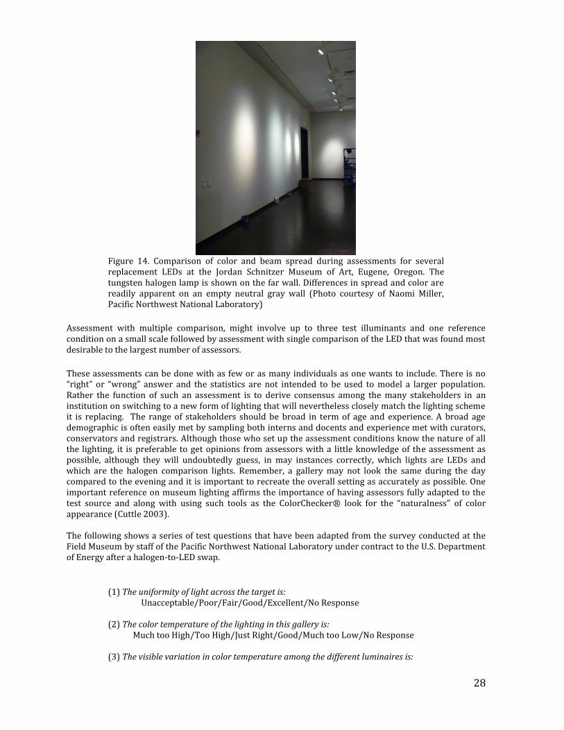
28
Figure 14. Comparison of color and beam spread during assessments for several replacement LEDs at the Jordan Schnitzer Museum of Art, Eugene, Oregon. The tungsten halogen lamp is shown on the far wall. Differences in spread and color are readily apparent on an empty neutral gray wall (Photo courtesy of Naomi Miller, Pacific Northwest National Laboratory)
Assessment with multiple comparison, might involve up to three test illuminants and one reference condition on a small scale followed by assessment with single comparison of the LED that was found most desirable to the largest number of assessors.
These assessments can be done with as few or as many individuals as one wants to include. There is no “right” or “wrong” answer and the statistics are not intended to be used to model a larger population. Rather the function of such an assessment is to derive consensus among the many stakeholders in an institution on switching to a new form of lighting that will nevertheless closely match the lighting scheme it is replacing. The range of stakeholders should be broad in term of age and experience. A broad age demographic is often easily met by sampling both interns and docents and experience met with curators, conservators and registrars. Although those who set up the assessment conditions know the nature of all the lighting, it is preferable to get opinions from assessors with a little knowledge of the assessment as possible, although they will undoubtedly guess, in may instances correctly, which lights are LEDs and which are the halogen comparison lights. Remember, a gallery may not look the same during the day compared to the evening and it is important to recreate the overall setting as accurately as possible. One important reference on museum lighting affirms the importance of having assessors fully adapted to the test source and along with using such tools as the ColorChecker® look for the “naturalness” of color appearance (Cuttle 2003). The following shows a series of test questions that have been adapted from the survey conducted at the Field Museum by staff of the Pacific Northwest National Laboratory under contract to the U.S. Department of Energy after a halogen-to-LED swap.
(1) The uniformity of light across the target is: Unacceptable/Poor/Fair/Good/Excellent/No Response
(2) The color temperature of the lighting in this gallery is: Much too High/Too High/Just Right/Good/Much too Low/No Response (3) The visible variation in color temperature among the different luminaires is:
29
Not Noticeable/Barely Noticeable/Slightly Noticeable/Noticeable/ Very Noticeable (Unacceptable)/No Response
(4) Glare from the light is: Disabling/Annoying/Noticeable, But Acceptable/Lower than Most/ Nonexistent/No Response (5) The lighting product shows _________________of the subject colors accurately. None/Some/Most/All/No Response (6) This product shows ____________________ of the subject forms clearly. None/Some/Most/All/No Response (7) Overall, the lighting in the gallery is: Too Bright/Somewhat Too Bright/Just Right/Somewhat Too Dim/
Too Dim/no Response (8) The artifact colors look ________________ rich/saturated. Very/Somewhat/Slightly/Not At All/No Response (9)The suitability of the lighting system for this gallery is: Superior/Good/Adequate/Marginal/Inadequate/No Response (10) The overall impression of the gallery under this lighting is: Exceptional/Favorable/Adequate/Inadequate in some respects/ Unacceptable/No Response
For these questions one simplifying assumption was made in questions 2 and 3, that all visible color differences in illuminants be attributed to color temperature alone rather than color temperature and/or Duv. This distinction is not thought worthy of making for the purposes of this assessment.
One additional distinction should be made. It is assumed that light sources be judged on an equal correlated color temperature basis. Some manufacturers supply LEDs both at 2700K and 3000K for incandescent replacement. There have been some experiences conducted on limited field trails that individuals may have strong opinions viewing color temperature with this degree of separation with preferences going in both directions. Therefore this assessment should be made independently of different products with the same correlated color temperature. These suggestions have been made to offer ideas as to how you might conduct your own evaluations in deciding which products to use or not use. The assessments may be as complicated or as simple as you want to make them and we reiterate that this activity is to help you make a decision and derive mutual agreement.
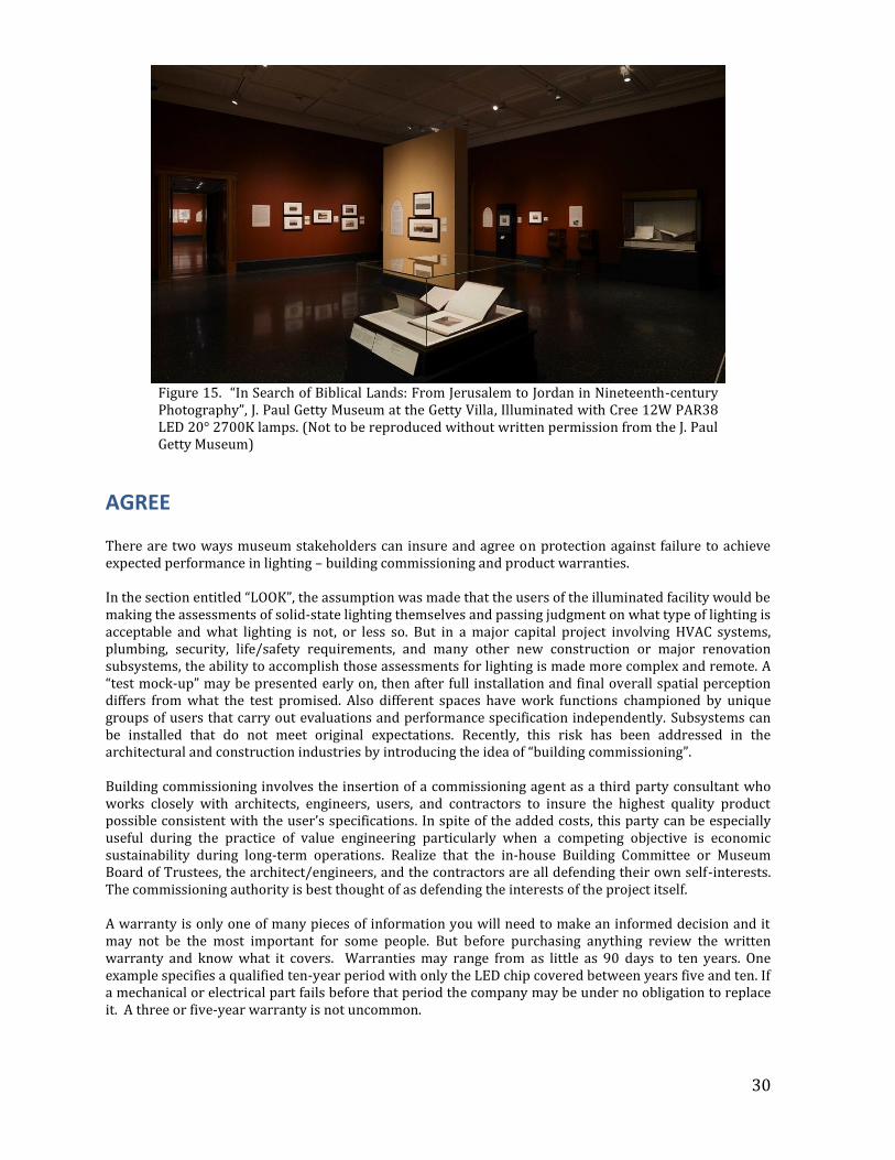
30
Figure 15. “In Search of Biblical Lands: From Jerusalem to Jordan in Nineteenth-century Photography”, J. Paul Getty Museum at the Getty Villa, Illuminated with Cree 12W PAR38 LED 20° 2700K lamps. (Not to be reproduced without written permission from the J. Paul Getty Museum)
AGREE There are two ways museum stakeholders can insure and agree on protection against failure to achieve expected performance in lighting – building commissioning and product warranties. In the section entitled “LOOK”, the assumption was made that the users of the illuminated facility would be making the assessments of solid-state lighting themselves and passing judgment on what type of lighting is acceptable and what lighting is not, or less so. But in a major capital project involving HVAC systems, plumbing, security, life/safety requirements, and many other new construction or major renovation subsystems, the ability to accomplish those assessments for lighting is made more complex and remote. A “test mock-up” may be presented early on, then after full installation and final overall spatial perception differs from what the test promised. Also different spaces have work functions championed by unique groups of users that carry out evaluations and performance specification independently. Subsystems can be installed that do not meet original expectations. Recently, this risk has been addressed in the architectural and construction industries by introducing the idea of “building commissioning”. Building commissioning involves the insertion of a commissioning agent as a third party consultant who works closely with architects, engineers, users, and contractors to insure the highest quality product possible consistent with the user’s specifications. In spite of the added costs, this party can be especially useful during the practice of value engineering particularly when a competing objective is economic sustainability during long-term operations. Realize that the in-house Building Committee or Museum Board of Trustees, the architect/engineers, and the contractors are all defending their own self-interests. The commissioning authority is best thought of as defending the interests of the project itself. A warranty is only one of many pieces of information you will need to make an informed decision and it may not be the most important for some people. But before purchasing anything review the written warranty and know what it covers. Warranties may range from as little as 90 days to ten years. One example specifies a qualified ten-year period with only the LED chip covered between years five and ten. If a mechanical or electrical part fails before that period the company may be under no obligation to replace it. A three or five-year warranty is not uncommon.
31
These warranties may offer poor consolation if they do not cover color consistency (See the Color consistency and appearance over time in Section 1) which is arguably the most critical performance parameter for an art museum. An LED installation may deliver a beautiful 3000K illumination at the start of life and shift to a lovely shade of magenta at eight “just noticeable differences” (JND) in three years. When the client protests they may learn their warranty contained no specific qualifier in terms of performance criteria and as far as the warranty coverage is concerned – as long as the LED turned, on it is performing fine. Nevertheless, some manufacturers do take their responsibilities and reputations very seriously and if a museum has a color quality performance issue within a 3-5 year period the manufacturer reserves the right to decide if replacement is justified even if that is not specified in the warranty.
One of the biggest difficulties with performance criteria in warranties is specifying the level of performance (mean value and acceptable level of variation), specification on how to monitor the criterion, and operational limitations. Few institutions are capable of monitoring total lumen output or illuminant color and the same retrofit lamp that performs well in a well-ventilated track luminaire may fail from overheating in an enclosed down light. In addition, some transformers are electronic and some are magnetic. Some have low minimum loading requirements and operate poorly with low-wattage LED replacement lamps. Some may cause color shift or flicker or unstable output, depending on circuit design. These potential incompatibilities between transformer and retrofit lamp are often difficult to anticipate, so it is important to test out the lamp in situ for more than a week to ensure it will behave as expected.
Some institutions have worked around warranty concerns by determining that the return on investment payback (ROI) is shorter than the warranty period. If L70 is 50,000 hours (70% loss of luminous intensity which is considered a standard end of life performance level) the more important value is that under a worse case scenario the lamp does not cost more than failure would cost otherwise without LEDs.
A suggested outline for a warranty review would be: Look for an ENERGY STAR rating first. This insures that the manufacturer maintains a 3-year
warranty on craftsmanship and materials. What is the stated warranty period and is it for a specified quality and quantity of light.
What does the warranty cover? Is it all-inclusive of do you need to read the “fine print” to discover
what it does not cover. What are the agreements or pass-through warranties on the main components such as LED chips,
LED packages, drivers or other components such as active cooling systems. What is the reputation or history of the company? Who do you call if something goes wrong?
What will be replaced or repaired in the event of a warranty claim? As technology changes
rapidly, will an acceptable replacement in five years or an equivalent product be available?
In conclusion, good warranties can be found. The best we have seen when framed in the context of an art museum is for LEDs warranted against manufacturers’ defects for lamps operated on a daily cycle (12-14 hours/day) for five years or 25,000 hours whichever comes first. But beyond lamp failure, they are also warranted for five years or 25,000 hours if any bulb exceeds 15% lumen depreciation (becomes dimmer) or shifts in color temperature more than +/- 100K. To avoid the difficulties described earlier on validating performance loss, this manufacturer maintains records on each lamp. One last piece of advice on warranties applies specifically to LED strip lighting. Insure that the warranty covers the product as a whole system. Drivers and transformers are not bundled into a single package like a PAR38 would be. It is possible to mix components that will not perform well together.
32
Recap: Getting the Most Out of Your LED Products See it before you buy it and preferably see two or three installed.
Require LM-79 testing for information on performance
Evaluate lumens, lumens/watt, beam spread
Check DOE CALiPER website for impartial test data
Use on non-dimming circuits, or test out LED, driver, transformer, dimmer, and loading of dimmer
and transformer to be sure they all work together for smooth dimming Specify products from companies you know or whom you trust, or that have a documented
support history Get a written warranty that includes light output and color variation performance, labor included
Check for EPA Energy Star® rating (Miller & Druzik, 2011)
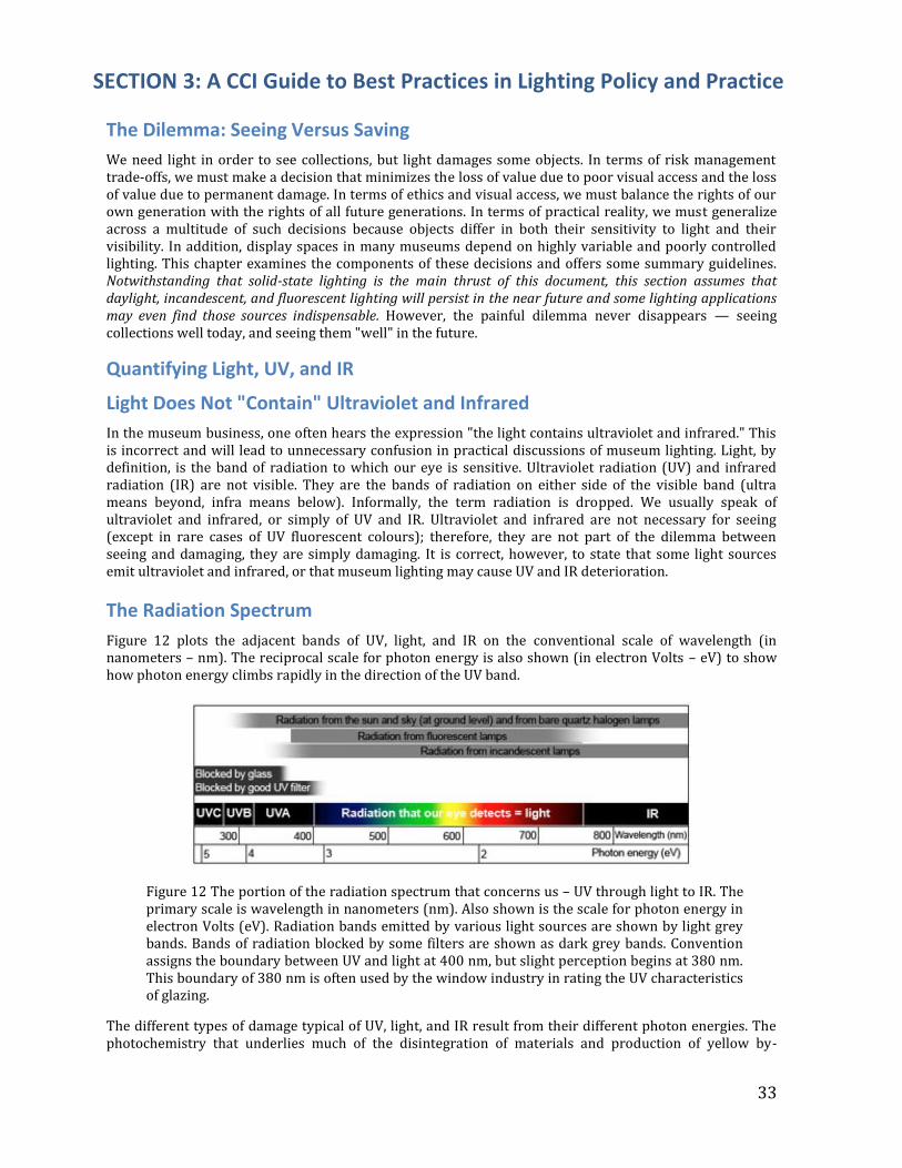
33
SECTION 3: A CCI Guide to Best Practices in Lighting Policy and Practice
The Dilemma: Seeing Versus Saving
We need light in order to see collections, but light damages some objects. In terms of risk management trade-offs, we must make a decision that minimizes the loss of value due to poor visual access and the loss of value due to permanent damage. In terms of ethics and visual access, we must balance the rights of our own generation with the rights of all future generations. In terms of practical reality, we must generalize across a multitude of such decisions because objects differ in both their sensitivity to light and their visibility. In addition, display spaces in many museums depend on highly variable and poorly controlled lighting. This chapter examines the components of these decisions and offers some summary guidelines. Notwithstanding that solid-state lighting is the main thrust of this document, this section assumes that daylight, incandescent, and fluorescent lighting will persist in the near future and some lighting applications may even find those sources indispensable. However, the painful dilemma never disappears — seeing collections well today, and seeing them "well" in the future.
Quantifying Light, UV, and IR
Light Does Not "Contain" Ultraviolet and Infrared
In the museum business, one often hears the expression "the light contains ultraviolet and infrared." This is incorrect and will lead to unnecessary confusion in practical discussions of museum lighting. Light, by definition, is the band of radiation to which our eye is sensitive. Ultraviolet radiation (UV) and infrared radiation (IR) are not visible. They are the bands of radiation on either side of the visible band (ultra means beyond, infra means below). Informally, the term radiation is dropped. We usually speak of ultraviolet and infrared, or simply of UV and IR. Ultraviolet and infrared are not necessary for seeing (except in rare cases of UV fluorescent colours); therefore, they are not part of the dilemma between seeing and damaging, they are simply damaging. It is correct, however, to state that some light sources emit ultraviolet and infrared, or that museum lighting may cause UV and IR deterioration.
The Radiation Spectrum
Figure 12 plots the adjacent bands of UV, light, and IR on the conventional scale of wavelength (in nanometers – nm). The reciprocal scale for photon energy is also shown (in electron Volts – eV) to show how photon energy climbs rapidly in the direction of the UV band.
Figure 12 The portion of the radiation spectrum that concerns us – UV through light to IR. The primary scale is wavelength in nanometers (nm). Also shown is the scale for photon energy in electron Volts (eV). Radiation bands emitted by various light sources are shown by light grey bands. Bands of radiation blocked by some filters are shown as dark grey bands. Convention assigns the boundary between UV and light at 400 nm, but slight perception begins at 380 nm. This boundary of 380 nm is often used by the window industry in rating the UV characteristics of glazing.
The different types of damage typical of UV, light, and IR result from their different photon energies. The photochemistry that underlies much of the disintegration of materials and production of yellow by-
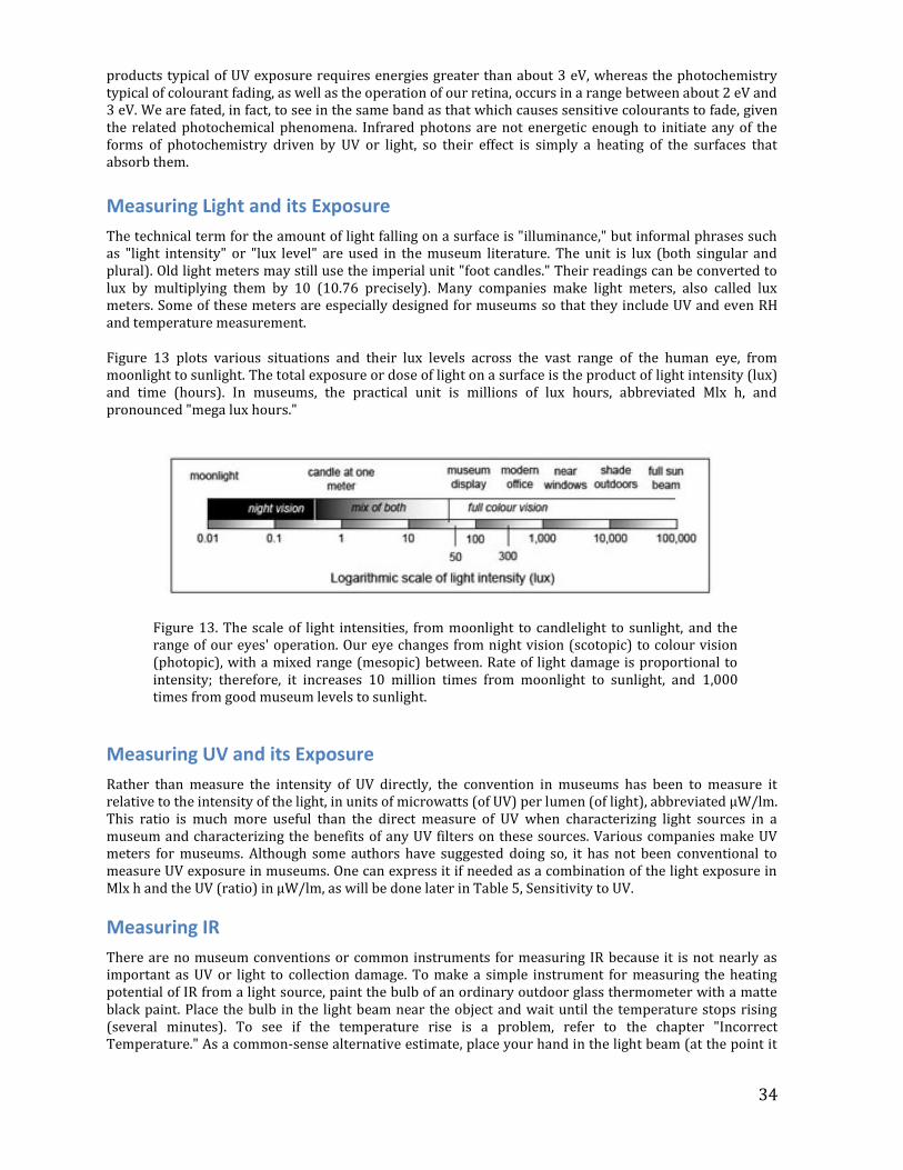
34
products typical of UV exposure requires energies greater than about 3 eV, whereas the photochemistry typical of colourant fading, as well as the operation of our retina, occurs in a range between about 2 eV and 3 eV. We are fated, in fact, to see in the same band as that which causes sensitive colourants to fade, given the related photochemical phenomena. Infrared photons are not energetic enough to initiate any of the forms of photochemistry driven by UV or light, so their effect is simply a heating of the surfaces that absorb them.
Measuring Light and its Exposure
The technical term for the amount of light falling on a surface is "illuminance," but informal phrases such as "light intensity" or "lux level" are used in the museum literature. The unit is lux (both singular and plural). Old light meters may still use the imperial unit "foot candles." Their readings can be converted to lux by multiplying them by 10 (10.76 precisely). Many companies make light meters, also called lux meters. Some of these meters are especially designed for museums so that they include UV and even RH and temperature measurement.
Figure 13 plots various situations and their lux levels across the vast range of the human eye, from moonlight to sunlight. The total exposure or dose of light on a surface is the product of light intensity (lux) and time (hours). In museums, the practical unit is millions of lux hours, abbreviated Mlx h, and pronounced "mega lux hours."
Figure 13. The scale of light intensities, from moonlight to candlelight to sunlight, and the range of our eyes' operation. Our eye changes from night vision (scotopic) to colour vision (photopic), with a mixed range (mesopic) between. Rate of light damage is proportional to intensity; therefore, it increases 10 million times from moonlight to sunlight, and 1,000 times from good museum levels to sunlight.
Measuring UV and its Exposure
Rather than measure the intensity of UV directly, the convention in museums has been to measure it relative to the intensity of the light, in units of microwatts (of UV) per lumen (of light), abbreviated μW/lm. This ratio is much more useful than the direct measure of UV when characterizing light sources in a museum and characterizing the benefits of any UV filters on these sources. Various companies make UV meters for museums. Although some authors have suggested doing so, it has not been conventional to measure UV exposure in museums. One can express it if needed as a combination of the light exposure in Mlx h and the UV (ratio) in μW/lm, as will be done later in Table 5, Sensitivity to UV.
Measuring IR
There are no museum conventions or common instruments for measuring IR because it is not nearly as important as UV or light to collection damage. To make a simple instrument for measuring the heating potential of IR from a light source, paint the bulb of an ordinary outdoor glass thermometer with a matte black paint. Place the bulb in the light beam near the object and wait until the temperature stops rising (several minutes). To see if the temperature rise is a problem, refer to the chapter "Incorrect Temperature." As a common-sense alternative estimate, place your hand in the light beam (at the point it
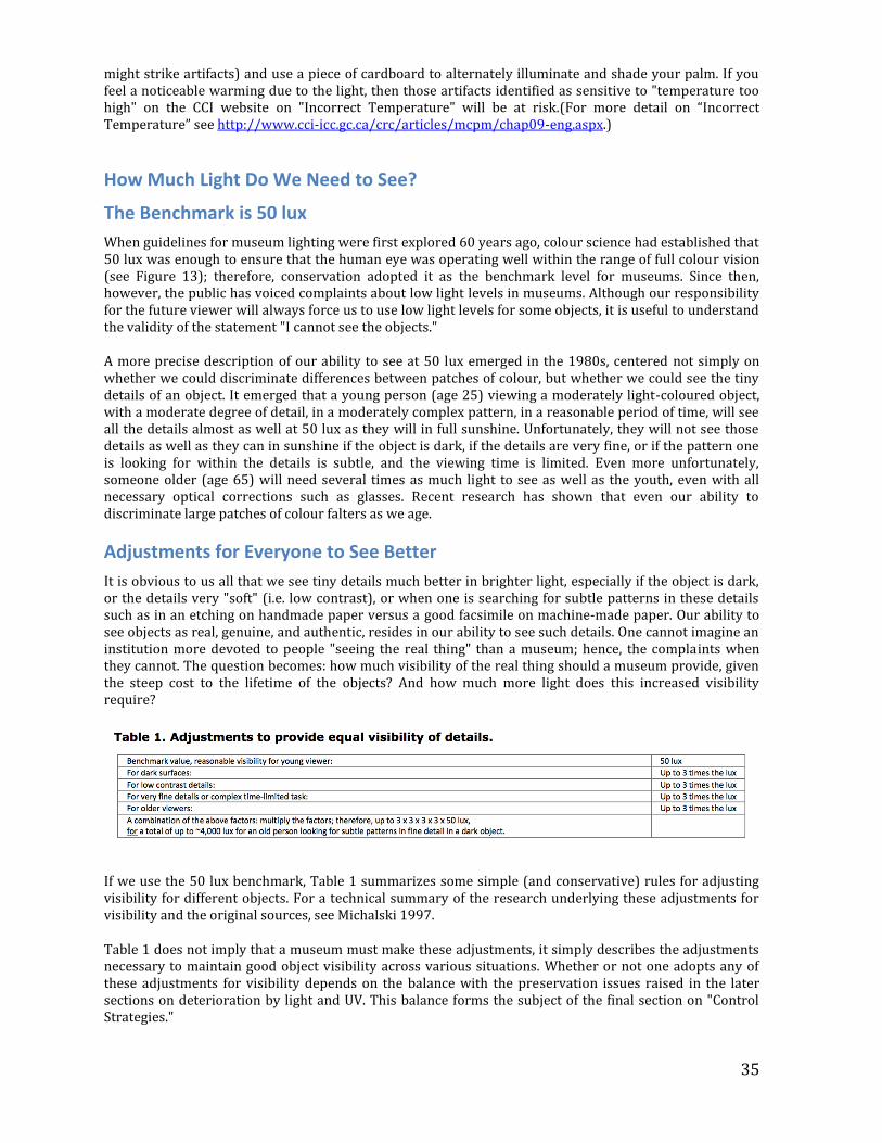
35
might strike artifacts) and use a piece of cardboard to alternately illuminate and shade your palm. If you feel a noticeable warming due to the light, then those artifacts identified as sensitive to "temperature too high" on the CCI website on "Incorrect Temperature" will be at risk.(For more detail on “Incorrect Temperature” see http://www.cci-icc.gc.ca/crc/articles/mcpm/chap09-eng.aspx.)
How Much Light Do We Need to See?
The Benchmark is 50 lux
When guidelines for museum lighting were first explored 60 years ago, colour science had established that 50 lux was enough to ensure that the human eye was operating well within the range of full colour vision (see Figure 13); therefore, conservation adopted it as the benchmark level for museums. Since then, however, the public has voiced complaints about low light levels in museums. Although our responsibility for the future viewer will always force us to use low light levels for some objects, it is useful to understand the validity of the statement "I cannot see the objects."
A more precise description of our ability to see at 50 lux emerged in the 1980s, centered not simply on whether we could discriminate differences between patches of colour, but whether we could see the tiny details of an object. It emerged that a young person (age 25) viewing a moderately light-coloured object, with a moderate degree of detail, in a moderately complex pattern, in a reasonable period of time, will see all the details almost as well at 50 lux as they will in full sunshine. Unfortunately, they will not see those details as well as they can in sunshine if the object is dark, if the details are very fine, or if the pattern one is looking for within the details is subtle, and the viewing time is limited. Even more unfortunately, someone older (age 65) will need several times as much light to see as well as the youth, even with all necessary optical corrections such as glasses. Recent research has shown that even our ability to discriminate large patches of colour falters as we age.
Adjustments for Everyone to See Better
It is obvious to us all that we see tiny details much better in brighter light, especially if the object is dark, or the details very "soft" (i.e. low contrast), or when one is searching for subtle patterns in these details such as in an etching on handmade paper versus a good facsimile on machine-made paper. Our ability to see objects as real, genuine, and authentic, resides in our ability to see such details. One cannot imagine an institution more devoted to people "seeing the real thing" than a museum; hence, the complaints when they cannot. The question becomes: how much visibility of the real thing should a museum provide, given the steep cost to the lifetime of the objects? And how much more light does this increased visibility require?
If we use the 50 lux benchmark, Table 1 summarizes some simple (and conservative) rules for adjusting visibility for different objects. For a technical summary of the research underlying these adjustments for visibility and the original sources, see Michalski 1997.
Table 1 does not imply that a museum must make these adjustments, it simply describes the adjustments necessary to maintain good object visibility across various situations. Whether or not one adopts any of these adjustments for visibility depends on the balance with the preservation issues raised in the later sections on deterioration by light and UV. This balance forms the subject of the final section on "Control Strategies."
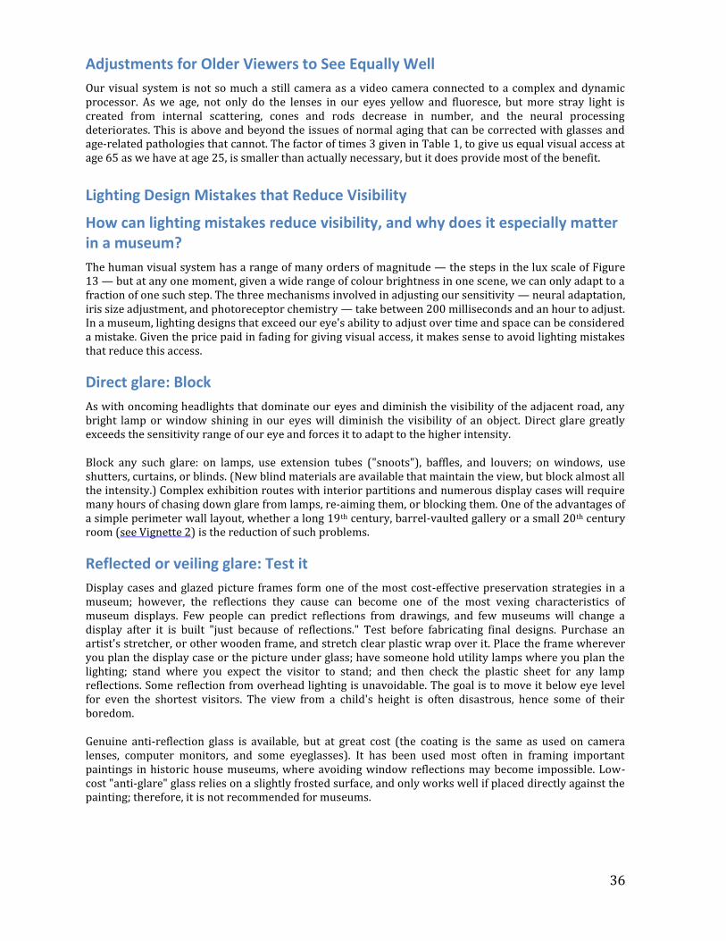
36
Adjustments for Older Viewers to See Equally Well
Our visual system is not so much a still camera as a video camera connected to a complex and dynamic processor. As we age, not only do the lenses in our eyes yellow and fluoresce, but more stray light is created from internal scattering, cones and rods decrease in number, and the neural processing deteriorates. This is above and beyond the issues of normal aging that can be corrected with glasses and age-related pathologies that cannot. The factor of times 3 given in Table 1, to give us equal visual access at age 65 as we have at age 25, is smaller than actually necessary, but it does provide most of the benefit.
Lighting Design Mistakes that Reduce Visibility
How can lighting mistakes reduce visibility, and why does it especially matter in a museum?
The human visual system has a range of many orders of magnitude — the steps in the lux scale of Figure 13 — but at any one moment, given a wide range of colour brightness in one scene, we can only adapt to a fraction of one such step. The three mechanisms involved in adjusting our sensitivity — neural adaptation, iris size adjustment, and photoreceptor chemistry — take between 200 milliseconds and an hour to adjust. In a museum, lighting designs that exceed our eye's ability to adjust over time and space can be considered a mistake. Given the price paid in fading for giving visual access, it makes sense to avoid lighting mistakes that reduce this access.
Direct glare: Block
As with oncoming headlights that dominate our eyes and diminish the visibility of the adjacent road, any bright lamp or window shining in our eyes will diminish the visibility of an object. Direct glare greatly exceeds the sensitivity range of our eye and forces it to adapt to the higher intensity.
Block any such glare: on lamps, use extension tubes ("snoots"), baffles, and louvers; on windows, use shutters, curtains, or blinds. (New blind materials are available that maintain the view, but block almost all the intensity.) Complex exhibition routes with interior partitions and numerous display cases will require many hours of chasing down glare from lamps, re-aiming them, or blocking them. One of the advantages of a simple perimeter wall layout, whether a long 19th century, barrel-vaulted gallery or a small 20th century room (see Vignette 2) is the reduction of such problems.
Reflected or veiling glare: Test it
Display cases and glazed picture frames form one of the most cost-effective preservation strategies in a museum; however, the reflections they cause can become one of the most vexing characteristics of museum displays. Few people can predict reflections from drawings, and few museums will change a display after it is built "just because of reflections." Test before fabricating final designs. Purchase an artist's stretcher, or other wooden frame, and stretch clear plastic wrap over it. Place the frame wherever you plan the display case or the picture under glass; have someone hold utility lamps where you plan the lighting; stand where you expect the visitor to stand; and then check the plastic sheet for any lamp reflections. Some reflection from overhead lighting is unavoidable. The goal is to move it below eye level for even the shortest visitors. The view from a child's height is often disastrous, hence some of their boredom.
Genuine anti-reflection glass is available, but at great cost (the coating is the same as used on camera lenses, computer monitors, and some eyeglasses). It has been used most often in framing important paintings in historic house museums, where avoiding window reflections may become impossible. Low-cost "anti-glare" glass relies on a slightly frosted surface, and only works well if placed directly against the painting; therefore, it is not recommended for museums.
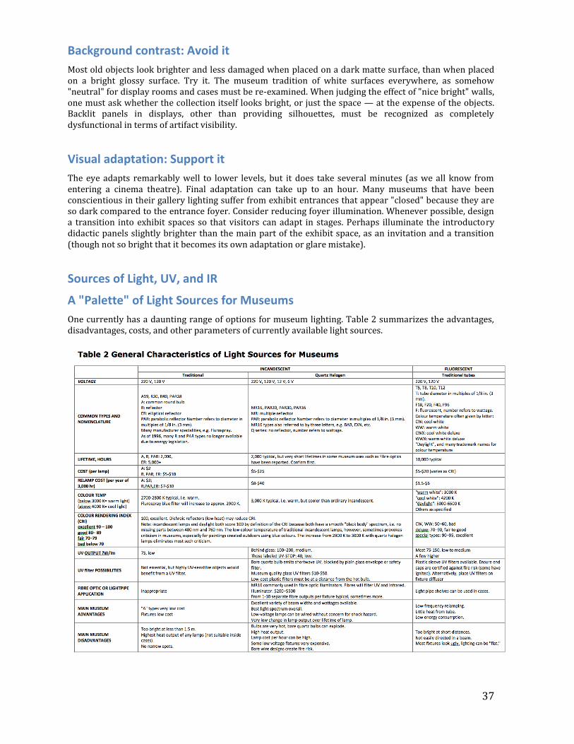
37
Background contrast: Avoid it
Most old objects look brighter and less damaged when placed on a dark matte surface, than when placed on a bright glossy surface. Try it. The museum tradition of white surfaces everywhere, as somehow "neutral" for display rooms and cases must be re-examined. When judging the effect of "nice bright" walls, one must ask whether the collection itself looks bright, or just the space — at the expense of the objects. Backlit panels in displays, other than providing silhouettes, must be recognized as completely dysfunctional in terms of artifact visibility.
Visual adaptation: Support it
The eye adapts remarkably well to lower levels, but it does take several minutes (as we all know from entering a cinema theatre). Final adaptation can take up to an hour. Many museums that have been conscientious in their gallery lighting suffer from exhibit entrances that appear "closed" because they are so dark compared to the entrance foyer. Consider reducing foyer illumination. Whenever possible, design a transition into exhibit spaces so that visitors can adapt in stages. Perhaps illuminate the introductory didactic panels slightly brighter than the main part of the exhibit space, as an invitation and a transition (though not so bright that it becomes its own adaptation or glare mistake).
Sources of Light, UV, and IR
A "Palette" of Light Sources for Museums
One currently has a daunting range of options for museum lighting. Table 2 summarizes the advantages, disadvantages, costs, and other parameters of currently available light sources.
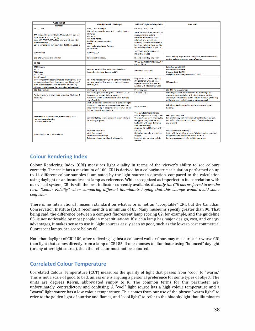
38
Colour Rendering Index
Colour Rendering Index (CRI) measures light quality in terms of the viewer's ability to see colours correctly. The scale has a maximum of 100. CRI is derived by a colourimetric calculation performed on up to 14 different colour samples illuminated by the light source in question, compared to the calculation using daylight or an incandescent lamp as reference. While recognized as imperfect in its correlation with our visual system, CRI is still the best indicator currently available. Recently the CIE has preferred to use the term “Colour Fidelity” when comparing different illuminants hoping that this change would avoid some confusion.
There is no international museum standard on what is or is not an "acceptable" CRI, but the Canadian Conservation Institute (CCI) recommends a minimum of 85. Many museums specify greater than 90. That being said, the difference between a compact fluorescent lamp scoring 82, for example, and the guideline 85, is not noticeable by most people in most situations. If such a lamp has major design, cost, and energy advantages, it makes sense to use it. Light sources easily seen as poor, such as the lowest-cost commercial fluorescent lamps, can score below 60.
Note that daylight of CRI 100, after reflecting against a coloured wall or floor, may measure a far worse CRI than light that comes directly from a lamp of CRI 85. If one chooses to illuminate using "bounced" daylight (or any other light source), then the reflector must not be coloured.
Correlated Colour Temperature
Correlated Colour Temperature (CCT) measures the quality of light that passes from "cool" to "warm." This is not a scale of good to bad, unless one is arguing a personal preference for some types of object. The units are degrees Kelvin, abbreviated simply to K. The common terms for this parameter are, unfortunately, contradictory and confusing. A "cool" light source has a high colour temperature and a "warm" light source has a low colour temperature. This comes from our use of the phrase "warm light" to refer to the golden light of sunrise and flames, and "cool light" to refer to the blue skylight that illuminates
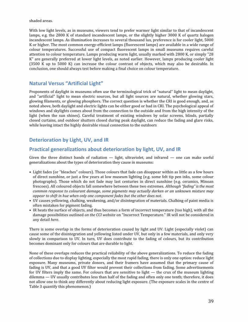
39
shaded areas.
With low light levels, as in museums, viewers tend to prefer warmer light similar to that of incandescent lamps, e.g. the 2800 K of standard incandescent lamps, or the slightly higher 3000 K of quartz halogen incandescent lamps. As illumination increases to several thousand lux, preference is for cooler light, 5000 K or higher. The most common energy-efficient lamps (fluorescent lamps) are available in a wide range of colour temperatures. Successful use of compact fluorescent lamps in small museums requires careful attention to colour temperature. Lamps producing warm light, usually marked with 2800 K, or simply "28 K" are generally preferred at lower light levels, as noted earlier. However, lamps producing cooler light (3500 K up to 5000 K) can increase the colour contrast of objects, which may also be desirable. In conclusion, one should always test before making a final choice on colour temperature.
Natural Versus “Artificial Light”
Proponents of daylight in museums often use the terminological trick of "natural" light to mean daylight, and "artificial" light to mean electric sources, but all light sources are natural, whether glowing stars, glowing filaments, or glowing phosphors. The correct question is whether the CRI is good enough, and, as noted above, both daylight and electric lights can be either good or bad in CRI. The psychological appeal of windows and skylights comes about from the connection to the outside and from the high intensity of the light (when the sun shines). Careful treatment of existing windows by solar screens, blinds, partially closed curtains, and outdoor shutters closed during peak daylight, can reduce the fading and glare risks, while leaving intact the highly desirable visual connection to the outdoors
Deterioration by Light, UV, and IR
Practical generalizations about deterioration by light, UV, and IR
Given the three distinct bands of radiation — light, ultraviolet, and infrared — one can make useful generalizations about the types of deterioration they cause in museums:
• Light fades (or "bleaches" colours). Those colours that fade can disappear within as little as a few hours of direct sunshine, or just a few years at low museum lighting (e.g. some felt tip pen inks, some colour photographs). Those which do not fade may last centuries in direct sunshine (e.g. ceramics, Minoan frescoes). All coloured objects fall somewhere between these two extremes. Although “fading” is the most common response to colourant damage, some pigments may actually darken or an unknown mixture may appear to shift in hue when only one component fades but the other does not.
• UV causes yellowing, chalking, weakening, and/or disintegration of materials. Chalking of paint media is often mistaken for pigment fading.
• IR heats the surface of objects, and thus becomes a form of incorrect temperature (too high), with all the damage possibilities outlined on the CCI website on "Incorrect Temperature." IR will not be considered in any detail here.
There is some overlap in the forms of deterioration caused by light and UV. Light (especially violet) can cause some of the disintegration and yellowing listed under UV, but only in a few materials, and only very slowly in comparison to UV. In turn, UV does contribute to the fading of colours, but its contribution becomes dominant only for colours that are durable to light.
None of these overlaps reduces the practical reliability of the above generalizations. To reduce the fading of collections due to display lighting, especially the most rapid fading, there is only one option: reduce light exposure. Many museums, private donors, and their framers have assumed that the primary cause of fading is UV, and that a good UV filter would prevent their collections from fading. Some advertisements for UV filters imply the same. For colours that are sensitive to light — the crux of the museum lighting dilemma — UV usually contributes less than half of the fading and often only one tenth; therefore, it does not allow one to think any differently about reducing light exposure. (The exposure scales in the centre of Table 3 quantify this phenomenon.)
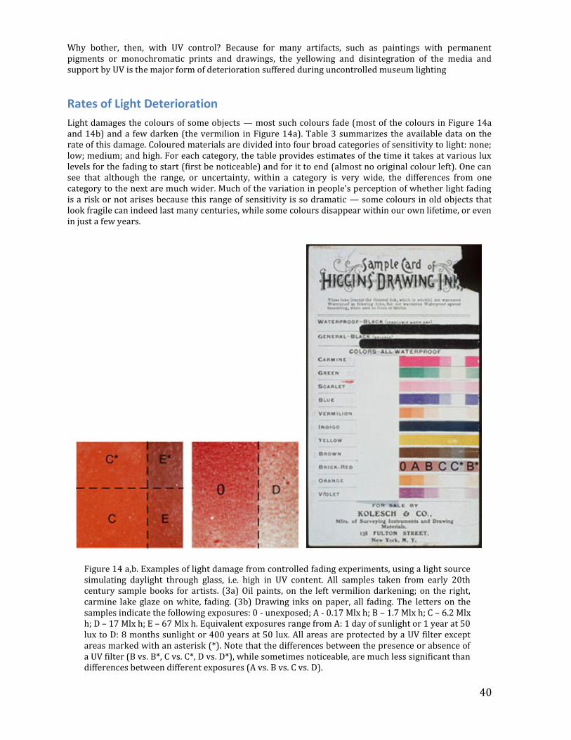
40
Why bother, then, with UV control? Because for many artifacts, such as paintings with permanent pigments or monochromatic prints and drawings, the yellowing and disintegration of the media and support by UV is the major form of deterioration suffered during uncontrolled museum lighting
Rates of Light Deterioration
Light damages the colours of some objects — most such colours fade (most of the colours in Figure 14a and 14b) and a few darken (the vermilion in Figure 14a). Table 3 summarizes the available data on the rate of this damage. Coloured materials are divided into four broad categories of sensitivity to light: none; low; medium; and high. For each category, the table provides estimates of the time it takes at various lux levels for the fading to start (first be noticeable) and for it to end (almost no original colour left). One can see that although the range, or uncertainty, within a category is very wide, the differences from one category to the next are much wider. Much of the variation in people's perception of whether light fading is a risk or not arises because this range of sensitivity is so dramatic — some colours in old objects that look fragile can indeed last many centuries, while some colours disappear within our own lifetime, or even in just a few years.
Figure 14 a,b. Examples of light damage from controlled fading experiments, using a light source simulating daylight through glass, i.e. high in UV content. All samples taken from early 20th century sample books for artists. (3a) Oil paints, on the left vermilion darkening; on the right, carmine lake glaze on white, fading. (3b) Drawing inks on paper, all fading. The letters on the samples indicate the following exposures: 0 - unexposed; A - 0.17 Mlx h; B – 1.7 Mlx h; C – 6.2 Mlx h; D – 17 Mlx h; E – 67 Mlx h. Equivalent exposures range from A: 1 day of sunlight or 1 year at 50 lux to D: 8 months sunlight or 400 years at 50 lux. All areas are protected by a UV filter except areas marked with an asterisk (*). Note that the differences between the presence or absence of a UV filter (B vs. B*, C vs. C*, D vs. D*), while sometimes noticeable, are much less significant than differences between different exposures (A vs. B vs. C vs. D).
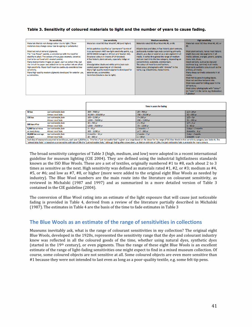
41
The broad sensitivity categories of Table 3 (high, medium, and low) were adopted in a recent international guideline for museum lighting (CIE 2004). They are defined using the industrial lightfastness standards known as the ISO Blue Wools. These are a set of textiles, originally numbered #1 to #8, each about 2 to 3 times as sensitive as the next. High sensitivity was defined as materials rated #1, #2, or #3; medium as #4, #5, or #6; and low as #7, #8, or higher (more were added to the original eight Blue Wools as needed by industry). The Blue Wool numbers are the main route into the literature on colourant sensitivity, as reviewed in Michalski (1987 and 1997) and as summarized in a more detailed version of Table 3 contained in the CIE guideline (2004).
The conversion of Blue Wool rating into an estimate of the light exposure that will cause just noticeable fading is provided in Table 4, derived from a review of the literature partially described in Michalski (1987). The estimates in Table 4 are the basis of the time to fade estimates in Table 3
The Blue Wools as an estimate of the range of sensitivities in collections
Museums inevitably ask, what is the range of colourant sensitivities in my collection? The original eight Blue Wools, developed in the 1920s, represented the sensitivity range that the dye and colourant industry knew was reflected in all the coloured goods of the time, whether using natural dyes, synthetic dyes (started in the 19th century), or even pigments. Thus the range of these eight Blue Wools is an excellent estimate of the range of light-fading sensitivities one might expect to find in a mixed museum collection. Of course, some coloured objects are not sensitive at all. Some coloured objects are even more sensitive than #1 because they were not intended to last even as long as a poor-quality textile, e.g. some felt tip pens.
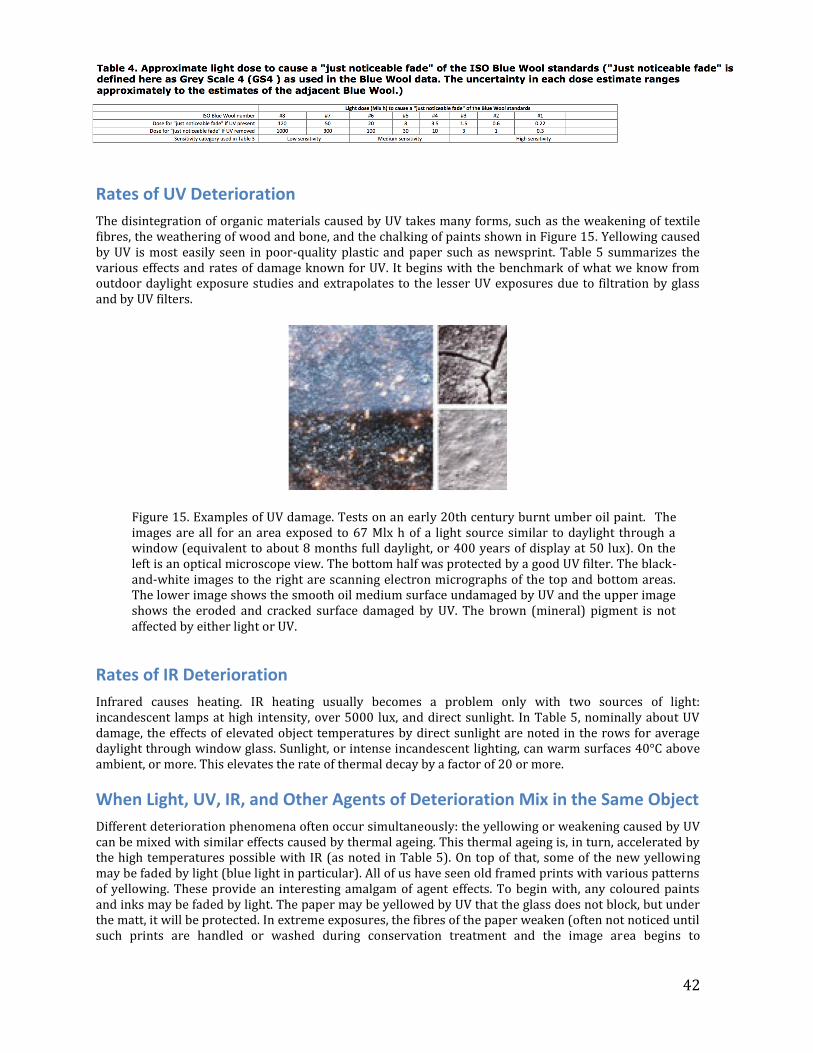
42
Rates of UV Deterioration
The disintegration of organic materials caused by UV takes many forms, such as the weakening of textile fibres, the weathering of wood and bone, and the chalking of paints shown in Figure 15. Yellowing caused by UV is most easily seen in poor-quality plastic and paper such as newsprint. Table 5 summarizes the various effects and rates of damage known for UV. It begins with the benchmark of what we know from outdoor daylight exposure studies and extrapolates to the lesser UV exposures due to filtration by glass and by UV filters.
Figure 15. Examples of UV damage. Tests on an early 20th century burnt umber oil paint. The images are all for an area exposed to 67 Mlx h of a light source similar to daylight through a window (equivalent to about 8 months full daylight, or 400 years of display at 50 lux). On the left is an optical microscope view. The bottom half was protected by a good UV filter. The black-and-white images to the right are scanning electron micrographs of the top and bottom areas. The lower image shows the smooth oil medium surface undamaged by UV and the upper image shows the eroded and cracked surface damaged by UV. The brown (mineral) pigment is not affected by either light or UV.
Rates of IR Deterioration
Infrared causes heating. IR heating usually becomes a problem only with two sources of light: incandescent lamps at high intensity, over 5000 lux, and direct sunlight. In Table 5, nominally about UV damage, the effects of elevated object temperatures by direct sunlight are noted in the rows for average daylight through window glass. Sunlight, or intense incandescent lighting, can warm surfaces 40°C above ambient, or more. This elevates the rate of thermal decay by a factor of 20 or more.
When Light, UV, IR, and Other Agents of Deterioration Mix in the Same Object
Different deterioration phenomena often occur simultaneously: the yellowing or weakening caused by UV can be mixed with similar effects caused by thermal ageing. This thermal ageing is, in turn, accelerated by the high temperatures possible with IR (as noted in Table 5). On top of that, some of the new yellowing may be faded by light (blue light in particular). All of us have seen old framed prints with various patterns of yellowing. These provide an interesting amalgam of agent effects. To begin with, any coloured paints and inks may be faded by light. The paper may be yellowed by UV that the glass does not block, but under the matt, it will be protected. In extreme exposures, the fibres of the paper weaken (often not noticed until such prints are handled or washed during conservation treatment and the image area begins to
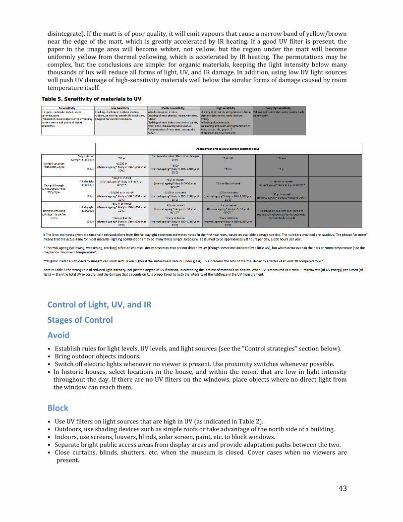
43
disintegrate). If the matt is of poor quality, it will emit vapours that cause a narrow band of yellow/brown near the edge of the matt, which is greatly accelerated by IR heating. If a good UV filter is present, the paper in the image area will become whiter, not yellow, but the region under the matt will become uniformly yellow from thermal yellowing, which is accelerated by IR heating. The permutations may be complex, but the conclusions are simple: for organic materials, keeping the light intensity below many thousands of lux will reduce all forms of light, UV, and IR damage. In addition, using low UV light sources will push UV damage of high-sensitivity materials well below the similar forms of damage caused by room temperature itself.
Control of Light, UV, and IR
Stages of Control
Avoid
• Establish rules for light levels, UV levels, and light sources (see the "Control strategies" section below). • Bring outdoor objects indoors. • Switch off electric lights whenever no viewer is present. Use proximity switches whenever possible. • In historic houses, select locations in the house, and within the room, that are low in light intensity
throughout the day. If there are no UV filters on the windows, place objects where no direct light from the window can reach them.
Block
• Use UV filters on light sources that are high in UV (as indicated in Table 2). • Outdoors, use shading devices such as simple roofs or take advantage of the north side of a building. • Indoors, use screens, louvers, blinds, solar screen, paint, etc. to block windows. • Separate bright public access areas from display areas and provide adaptation paths between the two. • Close curtains, blinds, shutters, etc. when the museum is closed. Cover cases when no viewers are
present.
44
Detect
• Look for signs of light and UV damage in the museum. • Use light meters and passive dosimeters. • Use museum UV meters. • Use a simple thermometer, if an IR heating problem is suspected.
Respond
• When faded objects are noted, determine causes and possible solutions. • When light meters and UV meters show unexpectedly high values in a location, determine causes and
solutions.
Recover
There is no true recovery possible from faded colours or disintegrated surfaces. Restoring such losses requires replacement by new material
Control Strategies for Different Degrees of Preservation
Introduction to different degrees of preservation
We can all agree on the general museum goal of reducing light damage at the same time as giving visual access, but, in practical terms, how much of each becomes a matter of increasing difficulty. There are three strategies, increasingly effective, but increasingly difficult:
• Follow a few basic measures designed to eliminate the extremes of light exposure. • Follow a simple rule based on the light intensity for minimum visibility, 50 lux. • Follow a few difficult rules to both minimize damage and maximize visibility.
A basic strategy for small museums: Eliminate all extreme light exposures
From the List of Basics introduced in section I, those that influence light and UV:
• A reliable roof that covers all organic artifacts (and preferably most inorganic artifacts). While this is obvious to even people outside museums, it also applies to large objects, such as historic vehicles or historic machines with paint. They cannot be expected to survive many years if exposed to sun and weather.
• Reliable walls, windows, and doors that block local weather, sunlight, local pests, amateur thieves, and vandals.
• Avoid areas of direct sunlight and intense spot lamps at close distances on all organic artifacts.
Results from the basic strategy
Assuming these measures avoid the extremes of 30,000 lux of average daylight, and fall somewhere between the 5000 lux of windows and the 500 lux of most office lighting, then low-sensitivity objects on display for a century will still appear colourful. Medium-sensitivity objects will have faded already in little more than a decade, and high-sensitivity objects will have been destroyed long ago, unless they were serendipitously set aside in dark forgotten places, boxes, envelopes, dowry chests, bound in volumes, etc., or were recently acquired from such places to be put on museum display. This is the tragedy of small historic house museums that acquire colourful new treasures from donors who had kept them in dark storage.
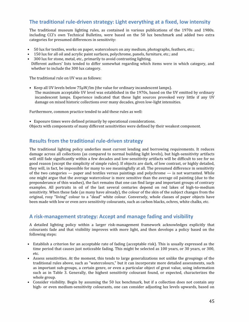
45
The traditional rule-driven strategy: Light everything at a fixed, low intensity
The traditional museum lighting rules, as contained in various publications of the 1970s and 1980s. including CCI's own Technical Bulletins, were based on the 50 lux benchmark and added two extra categories for presumed differences in sensitivity:
• 50 lux for textiles, works on paper, watercolours on any medium, photographs, feathers, etc.; • 150 lux for all oil and acrylic paint surfaces, polychrome, panels, furniture, etc.; and • 300 lux for stone, metal, etc., primarily to avoid contrasting lighting.
Different authors' lists tended to differ somewhat regarding which items were in which category, and whether to include the 300 lux category.
The traditional rule on UV was as follows:
• Keep all UV levels below 75μW/lm (the value for ordinary incandescent lamps). The maximum acceptable UV level was established in the 1970s, based on the UV emitted by ordinary
incandescent lamps. Experience indicated that these light sources provoked very little if any UV damage on mixed historic collections over many decades, given low-light intensities.
Furthermore, common practice tended to add these rules as well:
• Exposure times were defined primarily by operational considerations. Objects with components of many different sensitivities were defined by their weakest component.
Results from the traditional rule-driven strategy
The traditional lighting policy underlies most current lending and borrowing requirements. It reduces damage across all collections (as compared to normal building light levels), but high-sensitivity artifacts will still fade significantly within a few decades and low-sensitivity artifacts will be difficult to see for no good reason (except the simplicity of simple rules). If objects are dark, of low contrast, or highly detailed, they will, in fact, be impossible for many to see meaningfully at all. The presumed difference in sensitivity of the two categories — paper and textiles versus paintings and polychrome — is not warranted. While one might argue that the average watercolour is more sensitive than the average oil painting (due to the preponderance of thin washes), the fact remains that one can find large and important groups of contrary examples. All portraits in oil of the last several centuries depend on red lakes of high-to-medium sensitivity. When these fade (as many have already), the colour of the skin of the subject changes from the original, rosy "living" colour to a "dead" white colour. Conversely, whole classes of paper objects have been made with low or even zero sensitivity colourants, such as carbon blacks, ochres, white chalks, etc.
A risk-management strategy: Accept and manage fading and visibility
A detailed lighting policy within a larger risk-management framework acknowledges explicitly that colourants fade and that visibility improves with more light, and then develops a policy based on the following steps:
• Establish a criterion for an acceptable rate of fading (acceptable risk). This is usually expressed as the time period that causes just noticeable fading. This might be selected as 100 years, or 30 years, or 300, etc.
• Assess sensitivities. At the moment, this tends to large generalizations not unlike the groupings of the traditional rules above, such as "watercolours," but it can incorporate more detailed assessments, such as important sub-groups, a certain genre, or even a particular object of great value, using information such as in Table 3. Generally, the highest sensitivity colourant found, or expected, characterizes the whole group.
• Consider visibility. Begin by assuming the 50 lux benchmark, but if a collection does not contain any high- or even medium-sensitivity colourants, one can consider adjusting lux levels upwards, based on
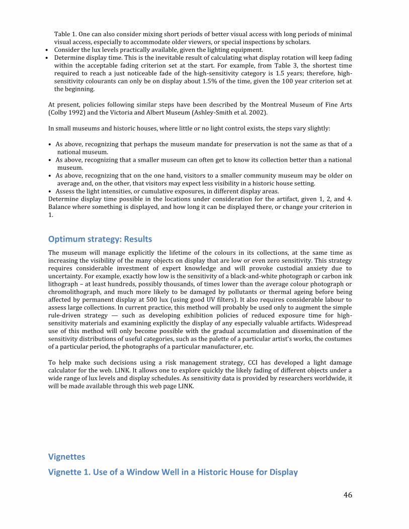
46
Table 1. One can also consider mixing short periods of better visual access with long periods of minimal visual access, especially to accommodate older viewers, or special inspections by scholars.
• Consider the lux levels practically available, given the lighting equipment. • Determine display time. This is the inevitable result of calculating what display rotation will keep fading
within the acceptable fading criterion set at the start. For example, from Table 3, the shortest time required to reach a just noticeable fade of the high-sensitivity category is 1.5 years; therefore, high-sensitivity colourants can only be on display about 1.5% of the time, given the 100 year criterion set at the beginning.
At present, policies following similar steps have been described by the Montreal Museum of Fine Arts (Colby 1992) and the Victoria and Albert Museum (Ashley-Smith et al. 2002).
In small museums and historic houses, where little or no light control exists, the steps vary slightly:
• As above, recognizing that perhaps the museum mandate for preservation is not the same as that of a national museum.
• As above, recognizing that a smaller museum can often get to know its collection better than a national museum.
• As above, recognizing that on the one hand, visitors to a smaller community museum may be older on average and, on the other, that visitors may expect less visibility in a historic house setting.
• Assess the light intensities, or cumulative exposures, in different display areas. Determine display time possible in the locations under consideration for the artifact, given 1, 2, and 4. Balance where something is displayed, and how long it can be displayed there, or change your criterion in 1.
Optimum strategy: Results
The museum will manage explicitly the lifetime of the colours in its collections, at the same time as increasing the visibility of the many objects on display that are low or even zero sensitivity. This strategy requires considerable investment of expert knowledge and will provoke custodial anxiety due to uncertainty. For example, exactly how low is the sensitivity of a black-and-white photograph or carbon ink lithograph – at least hundreds, possibly thousands, of times lower than the average colour photograph or chromolithograph, and much more likely to be damaged by pollutants or thermal ageing before being affected by permanent display at 500 lux (using good UV filters). It also requires considerable labour to assess large collections. In current practice, this method will probably be used only to augment the simple rule-driven strategy — such as developing exhibition policies of reduced exposure time for high-sensitivity materials and examining explicitly the display of any especially valuable artifacts. Widespread use of this method will only become possible with the gradual accumulation and dissemination of the sensitivity distributions of useful categories, such as the palette of a particular artist's works, the costumes of a particular period, the photographs of a particular manufacturer, etc.
To help make such decisions using a risk management strategy, CCI has developed a light damage calculator for the web. LINK. It allows one to explore quickly the likely fading of different objects under a wide range of lux levels and display schedules. As sensitivity data is provided by researchers worldwide, it will be made available through this web page LINK.
Vignettes
Vignette 1. Use of a Window Well in a Historic House for Display
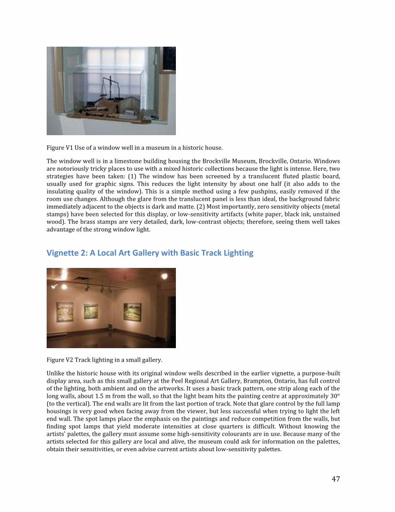
47
Figure V1 Use of a window well in a museum in a historic house.
The window well is in a limestone building housing the Brockville Museum, Brockville, Ontario. Windows are notoriously tricky places to use with a mixed historic collections because the light is intense. Here, two strategies have been taken: (1) The window has been screened by a translucent fluted plastic board, usually used for graphic signs. This reduces the light intensity by about one half (it also adds to the insulating quality of the window). This is a simple method using a few pushpins, easily removed if the room use changes. Although the glare from the translucent panel is less than ideal, the background fabric immediately adjacent to the objects is dark and matte. (2) Most importantly, zero sensitivity objects (metal stamps) have been selected for this display, or low-sensitivity artifacts (white paper, black ink, unstained wood). The brass stamps are very detailed, dark, low-contrast objects; therefore, seeing them well takes advantage of the strong window light.
Vignette 2: A Local Art Gallery with Basic Track Lighting
Figure V2 Track lighting in a small gallery.
Unlike the historic house with its original window wells described in the earlier vignette, a purpose-built display area, such as this small gallery at the Peel Regional Art Gallery, Brampton, Ontario, has full control of the lighting, both ambient and on the artworks. It uses a basic track pattern, one strip along each of the long walls, about 1.5 m from the wall, so that the light beam hits the painting centre at approximately 30° (to the vertical). The end walls are lit from the last portion of track. Note that glare control by the full lamp housings is very good when facing away from the viewer, but less successful when trying to light the left end wall. The spot lamps place the emphasis on the paintings and reduce competition from the walls, but finding spot lamps that yield moderate intensities at close quarters is difficult. Without knowing the artists' palettes, the gallery must assume some high-sensitivity colourants are in use. Because many of the artists selected for this gallery are local and alive, the museum could ask for information on the palettes, obtain their sensitivities, or even advise current artists about low-sensitivity palettes.
48
References (*Key Readings)
1. * Commission internationale de l'éclairage (CIE). Control of Damage to Museum Objects by Optical Radiation. CIE Technical Report, 157. Vienna: Commission internationale de l'éclairage, 2004.
2. * Ashley-Smith, J., A. Derbyshire, and B. Pretzel. "The Continuing Development of a Practical Lighting Policy for Works of Art on Paper and Other Object Types at the Victoria and Albert Museum." ICOM Committee for Conservation. In, Triennial meeting (13th), Rio de Janeiro, 22-27 September 2002:Preprints. London: James & James, 2002.
3. Colby, Karen M. "A Suggested Exhibition Policy for Works of Art on Paper. Journal of the International Institute for Conservation-Canadian Group. 17 (1992), pp. 3-11.
4. Michalski, S. "Damage to Museum Objects by Visible Radiation (Light) and Ultraviolet Radiation (UV)." In, Lighting in Museums, Galleries and Historic Houses. London: Museums Association, UKIC, and Group of Designers and Interpreters for Museums, 1987, pp. 3-16.
5. Michalski, S. "The Lighting Decision." In, Fabric of an Exhibition, Preprints of Textile Symposium 97. Ottawa: Canadian Conservation Institute, 1997, pp. 97-104.
Glossary
Blue Wool Scale: A scale for sensitivity to light fading, based on a set of eight different dyed pieces of wool. Footcandle: The Imperial unit of illuminance (light intensity) equal to one lumen per square foot or 10.76 lux. Just noticeable fade: "Just noticeable" varies with observers, situations, and industrial conventions, but for practical purposes, it means more or less just what it says. Technically, it is defined here using the ISO convention of "GS4," the first full step on the scale of five paired grey squares used to measure fading during lightfastness testing. In other words, it is the change in colour that the industry considered represented "just noticeable" from a practical user's perspective. In colourimetric units, GS4 represents ΔE=1.8. "Just noticeable" here must not be confused with the "just perceptible colour difference" that humans can see during optimal viewing circumstances, which is 2 to 6 times smaller than ΔE=1.8, depending on colour. (Colorimetic systems such as ΔE (CIELAB) are an attempt, currently far from perfect, to find a metric that will have as its unit the "just perceptible difference" across the whole colour space.) Lumen: The SI unit of luminous flux (light) used to rate the light output of lamps in manufacturer's catalogues. Lux: The SI (metric) unit of illuminance (light intensity) defined as 1 lumen per square meter. Direct noon sunlight is almost 100,000 lux; 1 lux is about the intensity of light from a candle at 1 m (photometric units were originally defined literally in terms of a "standard candle" at one metre). Mlx h: Abbreviation of megalux-hour. A museum unit of light exposure, or light dose. Equal to the product of light intensity (lux) and time (hours), quantified in millions of lux hours. The use of the time unit hours is incorrect within SI rules, but this particular usage is common in museum conservation literature. μW/lm: Abbreviation of microwatts per lumen. The museum unit of UV radiation. It is the ratio of UV intensity (in SI radiometric units μW/m2) to light intensity (in SI photometric units, lux=lumen/m2), hence the result μW/lm.
49
Sources for Solid-State Lighting Products Described in this Document
CREE LED Lighting, 635 Davis Drive, Suite 100, Morrisville, NC, USA 27560 Phone: (919) 991-7700, Fax: (919) 991-0730 [email protected] http://www.creeledlighting.com/ CRS Electronics, 129 Hagar St. Unit 5, Welland, Ontario, Canada, L3B5V9 Phone: (905) 788 9039 Phone: (888) 330.6786, Fax: (905) 788-2739 http://www.crselectronics.com/ ERCO Lighting, Inc., 160 Raritan Center Parkway, Suite 10, Edison, New Jersey 08837 USA Phone: (732) 225-8856 http://www.erco.com/homepage/homepage/start/en/en_start.php Juno Lighting Group, (Canada): (905) 792-7335 (USA): Phone: (800) 367-5866 http://www.junolightinggroup.com/ LEDnovation, Inc., 13053 W. Linebaugh Avenue, Suite 102, Tampa, Florida 33626 Brenda Baldwin, Phone (916) 396-9930 [email protected] http://www.lednovation.com Lighting Services Inc. (LSI), 2 Holt Drive Stony Point, NY 10980-1996 USA Phone: (845) 942-2800 USA & Canada: (800) 999-9574 Fax: (845) 942-2177 [email protected] http://www.lightingservicesinc.com/ General Electric Lighting, 1975 Noble Road Building 338E, East Cleveland, OH 44112-6300 Chip Richards, Phone: (916) 247-3158 (San Francisco), (216) 266-2419 (Worldwide) http://www.gelighting.com/na/ MSi, Solid State Lighting, 1342 South Powerline Road Deerfield Beach, FL 33442 (888) 778-9864, Local: 954 363-1085, Fax: 954 971-3725 [email protected] http://www.msissl.com/ Nichia America Corporation, 48561 Alpha Drive, Suite 100, Wixom Michigan 48393 Phone: (248) 349-9800 www.nichia.com Nora Lighting, 6505 Gayhart Street, City of Commerce, California 90040 Phone: (800) 686-6672 http://www.noralighting.com/Category.aspx?cid=683 http://www.noralighting.com/Category.aspx?cid=444 OSRAM Sylvania, 100 Endicott Street, Danvers MA 01923 Phone: (978) 750-2763 (Professional Series LED Products) http://www.lightsmanufacturer.com/2011/04/osram-sylvania-introduces-professional-series-led-bulbs.html
50
Philips Lighting U.S., 200 Franklin Square Drive, Somerset, NJ 08873. (800) 555-0050 http://www.usa.lighting.philips.com Small Corp, 19 Butternut Street, I-91 Industrial Park, Greenfield, MA, USA 01301 Phone (USA): (800) 392-9500. Phone (Canada): (413) 772-0889, Fax: (413) 773-7386 [email protected] ATTN: Mike Dunphy http://www.smallcorp.com Solais Lighting, Inc., 470 West Ave. Stamford, CT 06902-6359 Phone: (203) 683-6222 Fax: (888) 232-1086 [email protected] http://www.solaislighting.com/ Toshiba LED Lighting Division, 10435 Okanella, Suite 100, Houston, Texas 77041 Alex Avila, Phone: (713) 466-0277 x 3370 [email protected] http://www.toshiba.com/lighting/ http://www.toshiba.com/lighting/resources/documents.jsp Xicato USA, 4880 Stevens Creek Blvd., San Jose, California 95129 Ron Steen, (847) 525-5048 [email protected] http://www.xicato.com/
51
U.S. Department of Energy Internet Resources CALiPER Program. Product performance information: Summary reports, detailed test reports, benchmark reports, and CALiPER testing laboratories. http://www1.eere.energy.gov/buildings/ssl/caliper.html CALiPER’s Searchable Database http://www1.eere.energy.gov/buildings/ssl/search.html CALiPER Benchmark Reports: Testing of traditional lighting products against LEDs for a given application. http://www1.eere.energy.gov/buildings/ssl/benchmark.html The most recent Round 9 Caliper report (long term testing/Reliability) http://apps1.eere.energy.gov/buildings/publications/pdfs/ssl/caliper_round-9_summary.pdf Color Rendering Index and LEDs http://apps1.eere.energy.gov/buildings/publications/pdfs/ssl/color_rendering_index.pdf Color Quality of White LEDs http://apps1.eere.energy.gov/buildings/publications/pdfs/ssl/color_quality_of_white_leds.pdf LED Lifetimes http://apps1.eere.energy.gov/buildings/publications/pdfs/ssl/lifetime_white_leds.pdf LED Luminaire Reliability http://apps1.eere.energy.gov/buildings/publications/pdfs/ssl/arik_luminaire_raleigh2010.pdf Understanding Photometric Reports for SSL Products http://apps1.eere.energy.gov/buildings/publications/pdfs/ssl/understanding_photometric_reports.pdf Energy Star Criteria for SSL http://apps1.eere.energy.gov/buildings/publications/pdfs/ssl/portland2008_energystar_fs_0508v2.pdf http://apps1.eere.energy.gov/buildings/publications/pdfs/ssl/energystar_08fs.pdf DOE GATEWAY Demonstration Reports http://www1.eere.energy.gov/buildings/ssl/gatewaydemos_results.html Next Generation Luminaires—Design competition winners http://www.ngldc.org/09/winners.stm Status of the L Prize Competition: Early 2011 http://apps1.eere.energy.gov/buildings/publications/pdfs/ssl/lprize_competition_2011.pdf Materials and reports of DOE Solid-State Lighting Workshops http://www1.eere.energy.gov/buildings/ssl/presentations.html Energy Savings Potential of Solid-State Lighting in General Illumination Applications 2010 to 2030 http://apps1.eere.energy.gov/buildings/publications/pdfs/ssl/ssl_energy-savings-report_10-30.pdf
ENERGY STAR http://www.energystar.gov/
52
Bibliography Bohan, Suzanne, (2011), “Mercury in unrecycled CFL’s takes a toll on environment” April 7, Los Angeles Times. (May need to confirm statistics given here with EPA website, etc.) Dawson, T. (2010). "Development of efficient and durable sources of white light." Color. Technology, 126: 1-10. Fairchild, M. D. (2005). Color appearance models. Rochester, New York, John Wiley & Sons, Inc. Ishii, M., T. Moriyama, et al. (2008). "Color degradation of textiles with natural dyes and of blue scale standards exposed to white LED lamps: evaluation of white LED lamps for effectiveness as museum lighting." J. Light & Vis. Env. 32(4): 8. Miller, N. J. and J. R. Druzik (2011). “Solid-state lighting in Museums: Conserving energy, conserving art”, Presented at the National Archives and Records Administration 25th Annual Preservation Conference, University of Maryland Conference Center. March Rea, M. S. and J. P. Freyssinier-Nova (2008). "Color rendering: a tale of two metrics." COLOR: Research and Application, 33(2): 193-202. Rosenfeld, Scott, (2011) personal communication. Lighting designer, Smithsonian American Art Museum. United Nations General Assembly (1987) “Report to the World Commission on Environment and Development: Our Common Future”. Transmitted to the General Assembly as an Annex to document A/42/427 – Development and International Co-operation: Environment. U.S. Department of Energy (2010), “Demonstration assessment of light-emitting diode (LED) accent lighting”, Prepared by Pacific Northwest National Laboratory under Contract DE-AC05-76RL01830. http://www1.eere.energy.gov/buildings/ssl/gatewaydemos.html Boyce, P. R. (2003). Human factors in lighting. London, Taylor & Francis Group. Brodrick, J. (2011). Can museums measure up? LD+A. New York, Illuminating Engineering Society of North America. 41: 50-55. CIE (2004). Control of damage to museum objects by optical radiation. Paris, Commision Internationale de L'Eclairage: 30. Cuttle, C. (2003). Lighting by design. Oxford, Architectural Press, Elsevier Science. Davis, W. and Y. Ohno (2005). Toward an improved color rendering metric. Fifth International Conference on Solid State Lighting. I. T. Ferguson, J. C. Carrano, T. Taguchi and I. E. Ashdown. Proc. of SPIE Vol. 5941. DiMascio, M. and J. Loiter (2010). "Impending EISA lighting Standards: impact on consumers and energy efficiency lighting programs." National Association of Regulatory Commissioners, Winter Meeting. from http://www.narucmeetings.org/Presentations/Marianne DiMascio_AnnualMtg.pdf DOE, U. S. (2011). "LED Application Series: Dimming LEDs." from http://www.netl.doe.gov/ssl EPA (2011). "eGrid2010 Version 1.1." http://www.epa.gov/cleanenergy/documents/egridzips/eGRID2010V1_1_year07_SummaryTables.pdf
53
IEEE (2010). A Review of the literature on light flicker: ergonomics, biological attributes, potential health effects, and methods in which some LED lighting may introduce flicker. Mangum, S. R. (1998). "Effective constrained illumination of three-dimensional, light-sensitive objects." J. Illum. Eng. Soc., 27: 115-131. Ott, H., L. Plotz, et al. (2003) Dimming InGaN LEDs: Application Note, Osram Opto Semiconductor. http://www.osram-os.com Solais Lighting, I. (2012). LED lighting--separating fact from fiction, Solais White Paper. Stamford, CT, http://www.solais.com
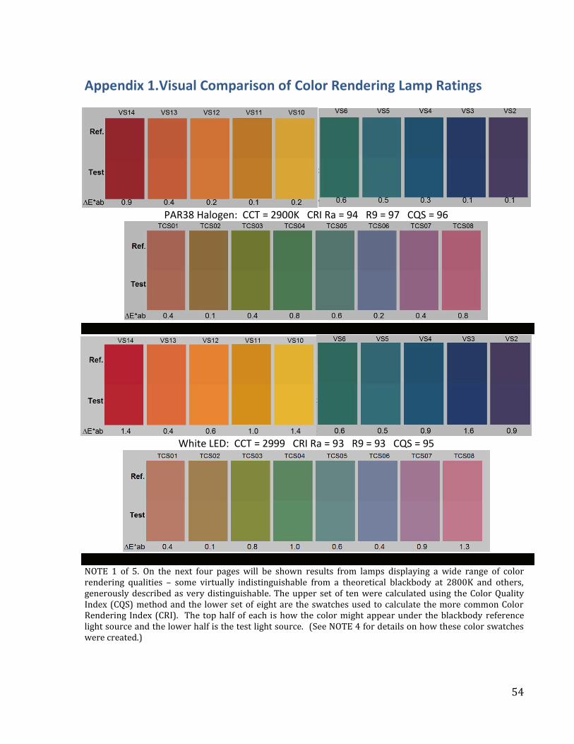
54
Appendix 1.Visual Comparison of Color Rendering Lamp Ratings
PAR38 Halogen: CCT = 2900K CRI Ra = 94 R9 = 97 CQS = 96
White LED: CCT = 2999 CRI Ra = 93 R9 = 93 CQS = 95
NOTE 1 of 5. On the next four pages will be shown results from lamps displaying a wide range of color rendering qualities – some virtually indistinguishable from a theoretical blackbody at 2800K and others, generously described as very distinguishable. The upper set of ten were calculated using the Color Quality Index (CQS) method and the lower set of eight are the swatches used to calculate the more common Color Rendering Index (CRI). The top half of each is how the color might appear under the blackbody reference light source and the lower half is the test light source. (See NOTE 4 for details on how these color swatches were created.)
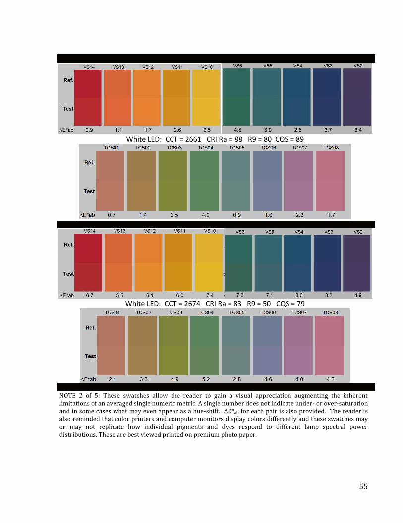
55
White LED: CCT = 2661 CRI Ra = 88 R9 = 80 CQS = 89
White LED: CCT = 2674 CRI Ra = 83 R9 = 50 CQS = 79
NOTE 2 of 5: These swatches allow the reader to gain a visual appreciation augmenting the inherent limitations of an averaged single numeric metric. A single number does not indicate under- or over-saturation and in some cases what may even appear as a hue-shift. ∆E*ab for each pair is also provided. The reader is also reminded that color printers and computer monitors display colors differently and these swatches may or may not replicate how individual pigments and dyes respond to different lamp spectral power distributions. These are best viewed printed on premium photo paper.
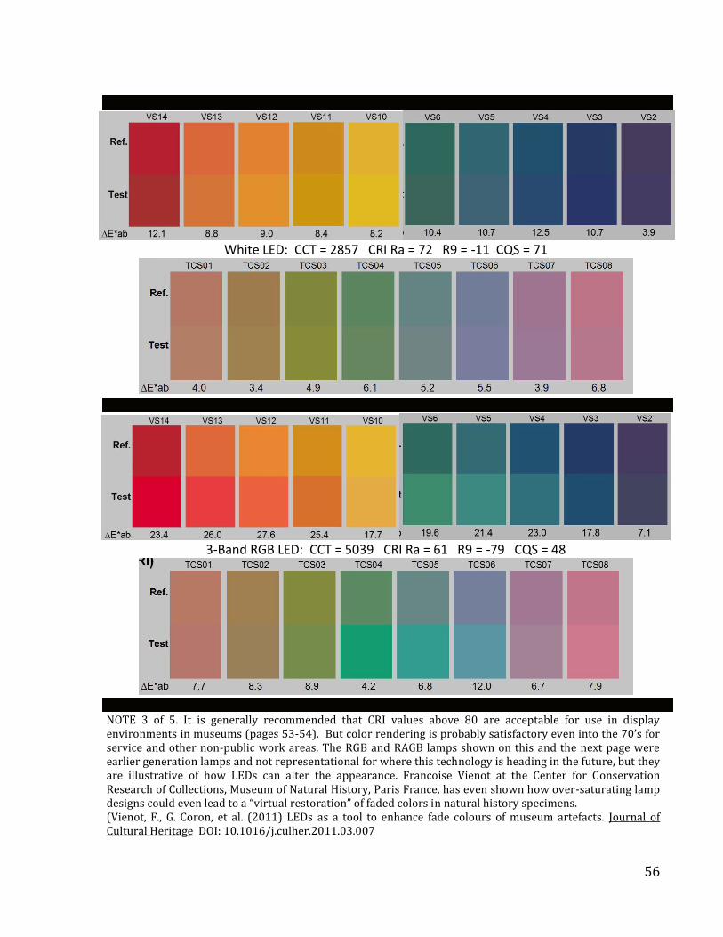
56
White LED: CCT = 2857 CRI Ra = 72 R9 = -11 CQS = 71
3-Band RGB LED: CCT = 5039 CRI Ra = 61 R9 = -79 CQS = 48
NOTE 3 of 5. It is generally recommended that CRI values above 80 are acceptable for use in display environments in museums (pages 53-54). But color rendering is probably satisfactory even into the 70’s for service and other non-public work areas. The RGB and RAGB lamps shown on this and the next page were earlier generation lamps and not representational for where this technology is heading in the future, but they are illustrative of how LEDs can alter the appearance. Francoise Vienot at the Center for Conservation Research of Collections, Museum of Natural History, Paris France, has even shown how over-saturating lamp designs could even lead to a “virtual restoration” of faded colors in natural history specimens. (Vienot, F., G. Coron, et al. (2011) LEDs as a tool to enhance fade colours of museum artefacts. Journal of Cultural Heritage DOI: 10.1016/j.culher.2011.03.007
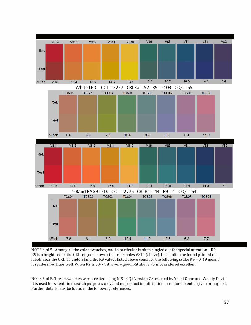
57
White LED: CCT = 3227 CRI Ra = 52 R9 = -103 CQS = 55
4-Band RAGB LED: CCT = 2776 CRI Ra = 44 R9 = 1 CQS = 64
NOTE 4 of 5. Among all the color swatches, one in particular is often singled out for special attention – R9. R9 is a bright red in the CRI set (not shown) that resembles VS14 (above). It can often be found printed on labels near the CRI. To understand the R9 values listed above consider the following scale: R9 = 0-49 means it renders red hues well. When R9 is 50-74 it is very good. R9 above 75 is considered excellent. NOTE 5 of 5. These swatches were created using NIST CQS Version 7.4 created by Yoshi Ohno and Wendy Davis. It is used for scientific research purposes only and no product identification or endorsement is given or implied. Further details may be found in the following references.
58
1. Y. Ohno, Color Rendering and Luminous Efficacy of White LED Spectra, Proc., SPIE Fourth International Conference on Solid State lighting, Denver, CO, August 2004, 5530, 88-98 (2004). 2. Y. Ohno, Spectral Design Considerations for Color Rendering of White LED Light Sources, Opt. Eng. 44, 111302 (2005). 3. W. Davis and Y. Ohno, Toward an Improved Color Rendering Metric, Fifth International Conference on Solid State Lighting, edited by Ian T. Ferguson, John C. Carrano, Tsunemasa Taguchi, Ian E. Ashdown, Proc. SPIE Vol. 5941, 59411G (2005).