guidelines lor safe design of shipping packages ... - iaea
TRANSCRIPT

IAEA-TECDOC-717
Guidelines lorsafe design of shipping packages
against brittle fracture
August 1993

FOREWORD
in 1992. the ninth meeting of the Standing Advisory Group on the Safe Transport ofRadioactive Materials recommended the publication of this TECDOC in an effort to promotethe widest debate on the criteria for the brittle fracture safe design of transport packages. Thepublished I AHA advice on the influence of brittle fracture on material integrity is containedin Appendix IX of the Advisory Material for the IAEA Regulations for the Safe Transport ofRadioactive Material (1985 Edition, as amended 1990). Safety Series No. 37. This guidanceis limited in scope, dealing only with ferritic steels in general terms. It is becoming morecommon for designers to specify materials other than austenitic stainless steel for packagingcomponents. The data on ferritic steels cannot be assumed to apply to other metals, hencethe need for further guidance on the development of relationships describing materialproperties at low temperatures.
The methods described in this TECDOC will be considered by the Revision Panel forinclusion in the 1996 Edition of the IAEA Regulations for the Safe Transport of RadioactiveMaterial and the supporting documents. If accepted by the Revision Panel, this advice willbe a candidate for upgrading to a Safety Practice. In the interim period, this TECDOC offersprovisional advice on brittle fracture evaluation. It is acknowledged that, at this stage, theviews expressed do not necessarily reflect those of the governments of Member States ororganizations under whose auspices this manuscript was produced.

CONTENTS
CHAPTER !. INTRODUCTION . . . . . . . . . . . . . . . . . . . . . . . . . . . . . . . . . . . . . . . . . . . 7
CHAPTER 2. DRAFT APPENDIX IX OF SAFETY SERIES No. 37:"GUIDELINES FOR SAFE DESIGN OF SHIPPING PACKAGESAGAINST BRITTLE FRACTURE" . . . . . . . . . . . . . . . . . . . . . . . . . . . . . . . 9
CHAPTER 3. JUSTIFICATION OF THE CRACK INITIATION METHODOLOGY . . . . . . 17
CHAPTER 4. JUSTIFICATION OF SAFETY FACTORS . . . . . . . . . . . . . . . . . . . . . . . . 23
CHAPTER 5. JUSTIFICATION OF REFERENCE FLAW SIZE . . . . . . . . . . . . . . . . . . . . 29
CHAPTER 6. JUSTIFICATION OF MATERIAL FRACTURE TOUGHNESS . . . . . . . . . . 33
CHAPTER 7. JUSTIFICATION OF STRESS CONSIDERATIONS . . . . . . . . . . . . . . . . . . 39
LIST OF ABBREVIATIONS . . . . . . . . . . . . . . . . . . . . . . . . . . . . . . . . . . . . . . . . . . . . . 49
CONTRIBUTORS TO DRAFTING AND REVIEW . . . . . . . . . . . . . . . . . . . . . . . . . . . . . . 51

Chapter 1
INTRODUCTION
l"\\o paragraphs of the 1985 Edition of IAEA Safety Series No. 6. the Regulations forthe Sale Transport of Radioactive Material (as amended 1990), infer the need for acceptablematerial properties at low temperatures, specifically at -40°C. These are para. 528 —a l\pe A requirement which also has to be met by Type B designs — and para. 556 — al >pe B requirement apphing only to Type B packages. The associated guidance informationin the 1985 Edition of IAEA Safety Series No. 37, Advisory Material for the IAEARegulations for the Safe Transport of Radioactive Material (as amended 1990), is essentiallycontained in Appendix IX, Influence of Brittle Fracture on Material Integrity. Appendix IXis ho\\e\er limited in that it deals only with ferritic steels and then only in general terms. Itrelies heavily on the extensive database of these materials" low temperature properties whichhave been compiled since World War II, beginning with the 'Liberty Ship' problems.
It is becoming more common for designers to specify materials other than austeniticstainless steel for nuciear packaging components. Such materials include ductile iron, alloysteel, titanium, depleted uranium, aluminum and borated stainless steel. All of these metalscan exhibit non-ductile failure at sufficiently low temperature and at stresses below the yieldstrength of the material, and specifically when flaws are present. The data on ferritic steelsassociated \\ith low temperature properties cannot be assumed to apply to other metals andtherefore the necessary relationships will have to be developed. To this end it was realizedthat further guidance to applicants/designers would be required and that revision ofAppendix IX of Safety Series No. 37 was therefore necessary.
Methods are described in this TECDOC which may be used by applicants/designersto demonstrate to competent authorities that the materials chosen will maintain the packageintegrity at lo\\ temperatures with respect to shielding, containment, and subcriticalityrequirements. More precisely, it details methods that can be used to technically justify thedesign depending upon the amount of materials data available, and specifies varying degreesof conservatism to be applied to these data to give assurance that failure will be prevented.
The effort to revise IAEA Safety Series No. 37 began with a US Department ofTransportation (DOT) proposal to the IAEA Continuous Review Committee, in June 1989,to incorporate criteria in Safety Series No. 37 to evaluate brittle fracture of nuclear materialtiansportation packages. The Continuous Review Committee accepted the US proposal. Atthe 8th meeting of SAGSTRAM, in December 1990, the Science and Technology Agency ofJapan further proposed to convene a no-cost Consultants Services Meeting (CSM) in order towrite the brittle fracture evaluation criteria. SAGSTRAM provided the IAEA with fivespecific objectives for the CSM to address:
(1 ) Review the paper by Sorenson, et al.: "A Proposal for an International Brittle FractureAcceptance Criterion for Nuclear Material Transport Cask Applications".
(2) Consider all packaging materials with brittle fracture characteristics.
(3) Address issues of "catastrophic flaw, failure prediction, and NDE methods forsignificant flaws".

(4) Prepare proposed advisory material for inclusion in Safety Series No. 37.
(5) Submit a Consultants Report to the IAEA.
The CSM convened on 9-11 October 1991 and wrote a draft revision to AppendixIX of Safety Series No. 37. The draft Appendix IX, Influence of Brittle Fracture on MaterialIntegrity, was given to CSM delegates to distribute among their own experts for a ninety dayreview. Comments from this review were then collated and evaluated at a second CSM,convened on 1-3 April 1992.
During the ninety day comment period, CSM members were also given writingassignments that form the basis of this TECDOC. The assignments were collated in February1992 and reviewed as a whole by the CSM members prior to the second meeting.
The second CSM focused on agreement of the final version of the draft Appendix IXto Safety Series No. 37 and improvements to this TECDOC. The draft Appendix, renamed"Guidelines for Safe Design of Shipping Packages against Brittle Fracture", will be consideredby the Revision Panel for inclusion in the 1996 revision of the Regulations and supportingdocuments. The TECDOC, which was agreed upon during the third CSM, convened on21-22 October 1992, offers provisional guidance to applicants/designers on brittle fractureevaluation in the interim period. If the draft Appendix is accepted by the Revision Panel,consideration must be given to upgrading this TECDOC to a Safety Practice. In the interim,Chapter 2 of this TECDOC contains the draft Appendix IX to Safety Series No. 37 in itsentirety. The numbering system chosen in Chapter 2 is appropriate to draft Appendix IX ofSafety Series No. 37. Chapters 3 to 7 provide technical justification for elements of theprovisional guidance detailed in Chapter 2.
Chapter 2
DRAFT APPENDIX IX OF SAFETY SERIES No. 37:"GUIDELINES FOR SAFE DESIGN OF SHIPPING PACKAGES
AGAINST BRITTLE FRACTURE"
This appendix provides guidance for evaluation of brittle fracture of structuralcomponents in radioactive materials (RAM) transport packages. Two basic methods arediscussed:
(i) I-Aaluation of ferritic steels using Charpy or nil-ductility transition temperaturemeasurements correlated to fracture resistance; and
( i i ) Assessment of fracture resistance based on a linear-elastic fracture mechanics designevaluation.
The first method is addressed to provide consistency with generally accepted practicefor e\ aluating ferritic steels. The second method, which accounts for the majority of guidancein this appendix, provides a methodology for evaluating brittle fracture that is suitable to a\\ide range of structural materials. This guidance does not preclude alternative methods thatare proper!} justified by the package designer and accepted by the competent authority.
Many materials are known to be less ductile at low temperatures and high loading ratesthan at moderate temperatures and static loading conditions. For example, the ability offerritic steels to absorb energy increases markedly over a narrow temperature range. Thehighest temperature at which complete brittle fracture occurs for ferritic steels is defined asthe nil-ductility transition temperature (NDTT). Similar behaviour is exhibited by othermaterials, such as ductile iron (DI), some aluminium alloys, and many plastics and elastomers.Loading of these materials under low-ductility conditions can lead to unstable crackpropagation \\ ith subsequent brittle fracture, even when the nominal stresses are less than thematerial yield strength. Small crack-like defects in the material may be sufficient to initiatethis unstable growth.
One mechanical property that characterizes a material's resistance to crack initiationis its initiation fracture toughness. Measurements of this property, as a function oftemperature and loading rate, trace out the transition from brittle to ductile material behaviour.This property is the parameter which quantifies a material's ability to resist crack initiationgiven a set of known loads (mechanical and environmental) in the presence of crack-likedefects. Depending upon the localized state of stress around the defect, and the extent of anyplasticity, the parameter is referred to as the stress intensity factor (K,), if the stress-strainconditions are linear-elastic; or, if the stress-strain conditions are elastic-plastic, the parameteris represented b> the energy line integral, J,. According to fundamental fracture mechanicstheon, the applied stress intensity factor (K,) or the energy line integral (J,) must be less thanthe material's fracture toughness (KI(muenal)) or (J^.^^!)) to preclude crack initiation andsubsequent brittle fracture (or ductile tearing in the case of elastic-plastic conditions). Theparticular value of K, {ma,er,ail or J|(matend|) that is acceptable for defining crack initiation dependson loading and environmental combinations of interest. For plaae strain conditions the criticalfracture toughness is termed Klc or J,c. Further, depending upon the loading rate, thelinear-elastic parameter is categorized as static (Klc) or dynamic (KId) fracture toughness. Ifthe initial depth of the defect, in combination with the applied loading, results in an applied

stress intensity factor that equals the material toughness, crack initiation is imminent and thedepth of the defect is referred to as the critical flaw depth. Under increased loading the crackmay propagate, leading to flaw instability and failure.
For conservatism, the recommended approach for the evaluation of the potential forbrittle fracture of transportation package designs should be based on the prevention of crackinitiation. The principles of linear-elastic fracture mechanics will normally be appropriate.I'nder some conditions, and as justified by the package designer and accepted by thecompetent authority, the principles of elastic-plastic fracture mechanics may be appropriate.In such cases, the prevention of crack initiation remains the governing criterion. Guidanceis provided in the following paragraphs for design against crack initiation in packagessubjected to the mechanical tests prescribed in paras 622. 625 or 627 of Safety Series No. 6.
The fundamental linear-elastic fracture mechanics equation describes structuralbehaviour as a function of applied stress and flaw depth:
where
K, - applied stress intensity factor (MPa T/m);C = constant based on flaw size, orientation and geometry of the structure;a = applied nominal tensile stress (MPa); anda = flaw depth (m).
Further, to preclude brittle fracture, the applied stress intensity factor should satisfy therelationship
where K,(maU:rlal) defines the fracture toughness. Where
'material] '
Eq. (IX. 1) can be combined with Eq. (IX. 3) to give an expression for the critical flaw depth,a,r. as
Krl,
Co
The purpose of the brittle fracture evaluation process is to ensure that the three parameters ofthis characterization (material fracture toughness, applied stress, and flawr size) satisfyEqs (IX. 1) and (IX.2); thereby precluding crack initiation.
10

methods
Criteria for the prevention of crack initiation and potentially unstable crack propagationin ferritic steel components, such as pressure vessels and piping used in the power, petroleum,and chemical process industries, are well developed, and have been codified into standardpractice by a number of national and international standard-writing bodies. These criteria canbe classified into two general types: (1) those based solely on material testing requirements,usually intended to demonstrate that some material property (e.g., impact energy) may becorrelated to fracture toughness to provide adequate margin against brittle fracture; or(2) those based on a combination of material testing, calculation of applied stresses, andworkn anship/inspection standards, intended to demonstrate that sufficient margin existsbetween the calculated design state and the measured material response state. Method 2follov-s the basic fracture mechanics approach described in Eqs (IX.1)-(IX.4). Otherevaluation methods are possible. Any approach suggested by the package designer is subjectto the approval of the competent authority.
Examples of the first method include the British Standards Institution BS 5500 [1], andthe ASME Sections III [2] and VIII [3]. These methods address, for example, ferritic steelswith substantial databases which relate impact energy (Charpy testing) to fracture toughness.In such cases, the Charpy impact energy can be used as an indirect indicator of materialtoughness. This approach may be used for a variety of high quality carbon andcarbon-manganese ferritic steels. The basic acceptance criterion for BS 5500 and the twoASME Code documents is the requirement of a minimum impact energy (or lateral expansion)from a Charpy V-notch test at a prescribed temperature.
Another example of the first method is the US Nuclear Regulatory Commission (NRC)regulatory guide, "Fracture Toughness Criteria for Ferritic Steel Shipping Cask ContainmentVessels with a Wall Thickness Greater Than Four Inches (0.1 m)", Reg. Guide 7.12 [4]. Thiscriterion prescribes levels of NDTT which must be achieved for ferritic steels, based onsection thickness and temperature. IT requires a minimum temperature difference betweenthe NDTT of the material and its lowest service temperature, as a function of sectionthickness. This temperature difference is based on correlations between NDTT and fracturetoughness. While this regulatory guide specifically addresses ferritic steels, the same approachcould be considered for other materials for which a correlation between NDTT and fractureresistance can be demonstrated. A practical problem in using this approach for other materialsis that the standardized test procedure ASTM A208 is valid for ferritic steels only. There areno standardized test methods for measuring the NDTT of other materials.
For the nuclear transportation industry, two significant drawbacks are apparent in thefirst method: (1) it relies solely on material properties to the exclusion of the designer's abilityto limit stresses through provision of impact-limiting devices and non-destructive examination(NDE) sufficient to detect and size prescribed flaws, and (2) the correlation of impact energyto fracture toughness is not applicable to a broad range of materials, thereby restricting thedesigner's use of alternative containment boundary materials.
Numerous examples of the second method that are valid for nuclear power plantcomponents can be identified. Such examples, although not directly applicable to transportpackage design evaluation, may be instructive in terms of their use of linear-elastic fracturemechanics principles. These examples include Appendix G of ASME Section III [5J; RCCMAppendix ZG of the French Nuclear Construction Code [6]; MITI Notification 501 from
11

Japan |7|; the German nuclear design code KTA 3201.2 [8]; the British Standards Institutiondocument PD 6493:1991 [9]: and the Confederation of Independent States (CIS) documentJ10]. These examples allow the designer the latitude of material selection together with theability to determine stresses and NDE requirements such that crack initiation and brittlefracture is precluded. The fundamental linear-elastic fracture mechanics approach is appliedin ail of these cases, although differences arise in the application of safety factors.
Safety /actors
Any safety factors that might be applied to Eq. (IX.2). or to the parameters that makeup Eq. (IX.2). must account for uncertainties in the calculation or measurement of theseparameters. These uncertainties might include those associated with the calculation of thestate of stress in the package, the examination of this package for defects, and themeasurement of material fracture toughness. In particular, concern about uncertainty innon-destructive examination (NDE) can be accommodated by appropriate conservatism in theselection of the reference flaw.
For the purposes of crack initiation prevention in transport package materials, thesafety factors for normal conditions of transport and hypothetical accident conditions shouldbe in general agreement with safety factors that have been de\eloped for similar loadingconditions in the referenced applications of the linear-elastic fracture mechanics approach.For example, for loading conditions that are expected to occur during the service life of thepackage, such as the normal conditions of transport, a safety factor of approximalel} 3 couldbe applied to Eq. ÜX.2). For unexpected (but design basis) loading conditions, such as thehypothetical accident conditions, a safety factor of approximately 1.4 could be applied toEq. (IX.2). It should be noted that this safety factor to Eq. (IX.2) can be applied to either theapplied stress, a. or to K1(malcnal). Therefore, this factor of safety can be interpreted asaccounting for uncertainty in the calculation of the stress state, or uncertainty in themeasurements of K.,(ma!enal), or as a combination of the t\\o. The factor of safety may beselected and justified bv the package designer, with acceptance by the competent authority.
Evaluation procedure
With the safety factors established, the general steps to be followed in order to apphthe recommended approach are: ( 1 ) postulation of a reference, or design basis. fla\\ at themost critical location in the packaging, and in the most critical orientation: (2) calculation ofthe stresses due to the mechanical tests described in paras 622. 625 and 627 of IAEA SafetySeries No. 6. ensuring that any required load combinations are considered; (3) calculation ofthe applied stress intensity factor at the tip of the design basis flaw; (4) determination of thefracture toughness material property; and (5) satisfaction of any margin of safety between thisapplied stress intensity factor and the accepted material fracture toughness value. This wi l lassure thai the flaw will not initiate as a result of the free drop and puncture tests, andtherefore wi l l not lead to unstable crack propagation and/or brittle fracture.
A variation on this sequence is for the mechanical tests to be used to demonstrate theresistance to brittle fracture directty. In this case, the test measurements ma\ be used foreither, or both, of two purposes — to provide inference of the stress field for applied stressintensity factor calculations, or to pro\ ide direct confirmation of the recommended marginagainst crack initiation. For the second of these, a crack must be placed in the prototype testpackaging location most vulnerable to fla\\ initiation from the mechanical test loads. The
12

relcrcnce tlau shape shall be semi-elliptical, with an aspect ratio (length to depth) of 6:1, orgreater. The tip of this artificial flaw should be as crack-like as possible, with a referenceHaw acuity that is justified by the package designer and accepted by the competent authority.An acuity of the radius at the extreme tip of the crack of not greater than 0.1 mm has beensuggested for ductile iron [11]. The depth of this flaw is determined by using stresses aspreviously calculated or inferred from strain measurements, and an appropriate factor of safetymust also be considered when computing the artificial flaw depth.
Recommendations for each of these procedural steps are provided in the followingparagraphs.
flaw consideration: With respect to either demonstration by analysis or demonstrationby test, the reference flaw shall be placed at the surface of the packaging containment wallat the location of the highest applied stress. Where the location of the highest applied stressis uncertain, multiple demonstrations may be required. The orientation of the reference flawshall be such that the highest tensile component of surface stress, as determined fromcalculations or experimental measurements, is normal to the plane of the flaw. The depth ofthe reference flaw shall be such that its relationship to volumetric examination sensitivity,detection uncertainty, rejection flaw size, and critical flaw size is justified. The reference flawdepth should be such that, in association with the demonstrated volumetric and surfaceexamination sensitivity, the non-detection probability is assured to be sufficiently small, asjustified by the package designer. A smaller depth may be chosen where the probability ofnon-detection can be demonstrated to be statistically insignificant.
The reference flaw of 6:1 aspect ratio should have an area, normal to the direction ofmaximum stress, greater than typical pre-service inspection indications that might be causeof rejection or repair of a fabricated packaging containment wall. However, since thereference flaw is a crack-like surface defect, rather than a more typical real defect (e.g.,subsurface porosity cloud or slag inclusion), the selection of this flaw size is extremelyconservative relative to workmanship standards.
Fracture toughness considerations: The calculated applied stress intensity factor shallbe shown to be less than the material fracture toughness value in Eq. (IX.2), as reduced bythe factor of safety. The method for determining the material fracture toughness shall beselected from three options, all of which are illustrated in Fig. 2.1. Each of these optionsincludes the generation of a statistically significant database of material fracture toughnessvalues obtained on product forms that are representative of material suppliers and packageapplications. The first two options shall include material fracture toughness values that arerepresentative of the strain rate, temperature and constraint conditions (e.g., thickness) of theactual package application. These same considerations apply to material fracture toughnessmeasurements used to support an elastic-plastic fracture evaluation.
Option 1 shall be based on the determination of a minimum value of fracturetoughness at a temperature of -40°C for a specific material. The minimum value is shownin Fig. 2.1 as representing a statistically significant data set, for a limited number of heatsfrom a limited number of material suppliers, obtained at appropriate loading rate andgeometric constraint conditions. The heats shall be representative of product formsappropriate for the particular package application.
13

Data set for specifictest program and material
Option 1
Lower-bound line drawnfor set of general data
a Option 2
-40Temperature (°C)
FIG. 2.1. Relative values of K, lmala,al) measurements based on the selection of options I, 2 or 3.
Option 2 shall be based on the determination of a lower-bound or near lower-boundvalue of material fracture toughness, KI(mattria,) = Klb, as shown in Fig. 2.1. This option wouldencompass the reference material fracture toughness determination for ferritic steels that isprescribed, for example, in the ASME Code Section III, Appendix G [5]. The lower-boundor near lower-bound value can be based on a composite of static, dynamic, and crack arrestfracture toughness data. An advantage of this option is the potential for reducing the testingprogramme for materials that can be referenced to the lower-bound or near lower-boundcurve. A relatively small, but suitable, number of data points may be sufficient todemonstrate the applicability of the curve to specific heats, grades or types of material.
Option 3 shall be based on the minimum value of a statistically significant fracturetoughness data set satisfying the static loading rate and crack tip constraint requirements ofASTM E399 [12]. The test temperature shall be at least as low as -40°C, but may have tobe reduced even lower to satisfy the ASTM E399 conditions, as shown in Fig. 2.1. Theconservatism of this option may be such that, as justified by the package designer andaccepted by the competent authority, a reduced factor of safety could be used.
Stress consideration: With respect to either demonstration by test or analysis, thecalculation of the applied stress intensity factor at the tip of the reference flaw shall be basedon maximum tensile stresses that are justified by the package designer and accepted by theCompetent Authority. The stresses may be determined by calculations for an unflawedpackage. When the stress field is inferred from surface strain measurements or either a scale -model or full-scale package performance test, the inferred stress field shall also be justified.The applied stress intensity factor may be calculated directly from stress analysis orconservatively calculated from handbook formulas that account for flaw shape and othergeometric and material factors.
14

Since the calculated stress fields may be dependent on impact limiter performance,mass distributions and structural characteristics of the package itself, the justification of thestresses \\ill in turn depend on the justification of analytical models. The justification ofstress fields interred from performance tests will depend on the justification of testinstrumentation characteristics, locations and data interpretation. Evaluation of eithercalculated or inferred stress fields may also involve an understanding of relevant dynamicmaterial and structural characteristics.
References
[I] BRITISH STANDARDS INSTITUTION, Specification for Unfired Fusion WeldedPressure Vessels, BS 5500, BSI, London (1991).
[2] AMERICAN SOCIETY OF MECHANICAL ENGINEERS, Boiler and PressureVessel Code, Section III. Division 1, Rules for the Construction of Nuclear PowerPlant Components, ASME, New York (1992).
[3] AMERICAN SOCIETY OF MECHANICAL ENGINEERS, Boiler and PressureVessel Code, Section VIII, Division 1, Rules for Construction of Pressure Vessels,ASME, New York (1992).
[4] NUCLEAR REGULATORY COMMISSION, Fracture Toughness Criteria for FerriticSteel Shipping Cask Containment Vessels with a Wall Thickness Greater Than FourInches (0.1 m), Regulatory Guide 7.12, NRC, Washington, DC (1991).
[5] AMERICAN SOCIETY OF MECHANICAL ENGINEERS, Boiler and PressureVessel Code, Section III, Division 1 — Appendices, Appendix G: Protection AgainstNonductile Failure, ASME, New York (1992).
[6] French Nuclear Construction Code; RCCM: Design and Construction Rules forMechanical Components of PWR Nuclear Islands, Subsection Z, Appendix ZG, FastFracture Resistance (1985).
[7] JAPANESE MINISTRY FOR INTERNATIONAL TRADE AND INDUSTRY,Technical Criteria for Nuclear Power Structure, Notification No. 501.
[8] Sicherheit technische Regel des KTA. Komponenten des Primaerkreises vonLeichtwasserreaktoren; Teil 2: Auslegung, Konstruktion und Berechnung, KTA 3201.2,Fassung 3/84, Bundesanzeiger. Bonn (1985).
[9] BRITISH STANDARDS INSTITUTION, Guidance on Methods for Assessing theAcceptability of Flaws in Fusion Welded Structures, PD 6493, BSI, London (1991).
[10] Gosstandart, Determination of Fracture Toughness Characteristics Under StaticLoading, GOST 25.506-85 (1985); and Determination of Fracture ToughnessCharacteristics Under Dynamic Loading, RD-50-344-8 (1983).
[ I I ] CENTRAL RESEARCH INSTITUTE OF ELECTRIC POWER INDUSTRY, Researchon Quality Assurance of Ductile Cast Iron Casks, EL 87001, CRIEPI, Tokyo (1988).
[12] AMERICAN SOCIETY FOR TESTING AND MATERIALS, Annual Book of ASTMStandards: Standard Test Method for Plane-Strain Fracture Toughness of MetallicMaterials, Volume 03.01, ASTM E399-83, Philadelphia, PA (1983).
15

Chapter 3
JUSTIFICATION OF THE CRACK INITIATION iMETHODOLOGY
! he fundamental engineering discipline that defines the ability of material to resistcrack init iat ion and subsequent crack growth is fracture mechanics. As with most physicalphenomena, fracture mechanics is a large field of study and is therefore divided into subsetsba.-^ed on material response to mechanical and environmental loadings. A material's responseto such loadings can be characterized as either linear-elastic or elastic-plastic. These tworesponses are a function of material properties and section design. In general, many materials\\ilh. for example, a body centred cubic or hexagonal close packed atomic structure have thepotential to fail in a brittle manner (i.e. linear-elastic response). Further, the thickness of thematerial influences its response; as constraint in the section increases, the potential for brittle1 raclure increases.
Fracture mechanics design can also be based on either crack initiation or crack arrest.The crack initiation criterion precludes any crack initiation resulting from applied stresses.The crack arrest criterion allows crack initiation, but asserts that any growth of the crack willarrest prior to catastrophic collapse of the structural component. Fracture mechanics guidancein Chapter 2 of this document is based on linear-elastic behaviour and the crack initiationcriterion. This approach results in the maximum conservatism in evaluating the brittle fracturepotential in package designs. In addition, this approach avoids the need to deal withuncertainty in the calculation or measurement of crack growth. The justification for thisapproach will follow after a brief historical rev:-', • of the development of the field of fracturemechanics.
The de\ elopment in the field of fracture mechanics technology can be divided intothree stages. The first stage spans the period from 1913 to 1947, during which thepredominant mechanical representation of brittle fracture was one published by Griffith in1920. This theory was based, in part, on analytical results published by Inglis in 1913.
The second stage of development covers the period from 1947 to 1965, the year theAmerican Society for Testing and Materials (ASTM) Committee E24 on Fracture Testing wasestablished. This stage in the development of fracture mechanics can be subdivided into twoperiods. The first 12 \ears. 1947 to 1959, represent the period during which fracturemechanics technology was developed under the leadership of G.R. Irwin arid was applied tothe design of engineering structures. Irwin recognized that most of the analytical methodsneeded to formulate the mechanics of fracture on a sound technical basis were available. Thesecond period. 1959 to 1965, is marked by the formation of an ASTM Special TechnicalCommittee. This committee studied the various methodologies that were available to analysefracture and adopted the fracture mechanics technology developed by Irwin. This recognizedthe engineering significance of the technical development and facilitated its use and furtherdevelopments. Essential!}, the ASTM Special Committee accepted a leadership role inextending the development of fracture mechanics. Between 1960 and 1965, the applicationof this technology \\as extended to the study of fatigue crack growth, stress corrosioncracking, and elastic-plastic fracture. First reports issued by the Special Technical Committeein I960 contributed significantly to the acceptance and to the advancement of fracturemechanics technologv.
17

The third stage in the progression of fracture mechanics technology started with theformation of Committee E24 on Fracture Testing in 1965 and continues to the present time.The formation of this committee provided a forum for the development and application of thistechnology by many scientists and engineers in the United States and around the world.
Engineering applications of fracture mechanics have matured and become essentialover the years. Initial fracture mechanics awareness grew out of the fracture failures in someof the USA World War II "Liberty Ships'. More sophisticated applications were thenidentified with the aircraft industry and extended to other applications such as heavy rotatingcomponents of large steam turbine electric generators.
As the necessity of this engineering discipline has grown and been accepted byindustry, consensus codes and standards have been developed in order to assure consistentapplication of the methodology. ASTM provides the authoritative test procedures formeasuring fracture toughness of material specimens and there are numerous design codesthroughout the world that embrace fracture mechanics criteria for evaluating brittle fracture.
Applying fracture mechanics criteria for the evaluation of brittle fracture in structuralcomponents of RAM transport packages is a logical extension of the fracture mechanicsmethodology. Clearly, these criteria must assure both the user and the regulator that theapproach can assure that brittle fracture will not occur and that there is a reasonable level ofconservatism in the design.
Linear-elastic fracture mechanics and the crack initiation criterion were selected as thebasis for the draft Appendix IX guidance because these approaches result in conservativedesigns that provide significant margin against brittle failure. Linear-elastic fracturemechanics represent complete brittle behaviour of a structural material subjected to mechanicaland environmental loadings. In reality, candidate structural materials for RAM packagesexhibit, at worst, a mixed-mode behaviour (e.g. partial brittle fracture and partial ductiletearing), and often exhibit a completely ductile response. A ductile material mitigates stressconcentrations through yielding and redistribution of the applied stresses over a larger area.Applying the linear-elastic criterion to elastic-plastic materials requires the conversion of anelastic-plastic measurement, J]c, to the linear-elastic K,c. This is a conservative conversion aslong as the loadings do not result in through-wall yielding (a condition that is not permissibleby standard structural criteria). The effect of the conversion acts to reduce the allowable flawsize in the structural component and thereby increases the safety of the design.
Selection of the crack initiation criterion has a strong institutional basis. Conductinga certification test that results in crack initiation and subsequent crack growth with eventualarrest may be arguable on a technical basis, but does not provide a great degree of confidencefor the general public. Assurance that a crack will not even initiate provides a much bettersafety argument than to argue that a crack may initiate and grow, but that it will arrest beforecatastrophic failure occurs.
Crack initiation is also conservative because the dynamic effects associated with crackarrest are much more pronounced. For a typical package, hypothetical accident conditionsresult in peak loadings over a time frame of approximately 20 milliseconds. Although thistime may seem short, it is a rather long load duration and material properties do not differmuch from static conditions. For a crack arrest criterion, a propagating crack travels atapproximately the speed of sound. Material properties do change at these very high strainrates and, in general, exhibit more linear-elastic (i.e., brittle) behaviour as rates increase.
18
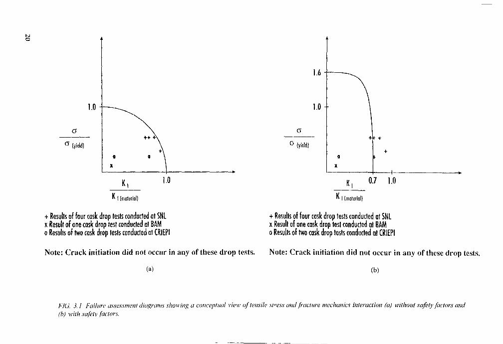
Failure assessment diagrams are one way to relate mechanics of material's failurelheor\ \\iih fracture mechanics failure theory. The ordinale in Fig. 3,1 (a) tracks tensile stressand assumes failure occurs at an applied tensile stress equivalent to the yield stress of thematerial. The abscissa tracks the stress intensity factor. K, and assumes failure occurs whenK, reaches the material's fracture toughness value, Kic. The quadrant drawn from 1.0 on theordinale to 1.0 on the abscissa represents the boundary of failure. Designs falling within thequadrant would not fail from either excessive tensile strain or from an excessive stressintensity factor. Since the assumptions that ductile rupture occurs at stresses equal to the yieldstrength and brittle fracture occurs at slress intensity factors equal to crack initiation toughnessare very conservative relative to actual failure points, this failure boundary is understated.
Results of actual drop test programmes are plotted in Fig. 3.1. Data from the SandiaNational Laboratories MOSAIK Drop Test Program [3.1], the German Bundesanstalt fuerMateriaiforschung und -pruefung (BAM) VHLW Drop Test Program [3.2] and the JapaneseCentral Research Institute of Electric Power Industry (CRIEPI) [3.3] full-scale drop testprogramme relate test results to the failure boundary. These drop test programmesdemonstrated the integrity of monolithic ductile iron packages subjected to Type B accidentcondition testing.
Figure 3.1(b) represents a failure assessment diagram with safety factors introduced.For hypothetical accident conditions, regulations allow stresses to exceed the yield strength.The NRC, for example, allows the applied stress to reach 1.6 times the yield strength. If theductile rupture failure point corresponds to the ultimate strength of the material, 1.6 times theyield strength corresponds to a safety factor of between 1.25 and 1.5, depending upon whetherthe material is ferritic or austenitic. For ihe brittle fracture axis, a safety factor of 1.4 (or asafety coefficient of 0.7) hat, been applied to the stress intensity factor. This acts to changethe failure boundary from a quadrant to an approximate quarter-ellipse. Visually, it is shownthat a higher degree of conservatism is placed on the stress intensity factor than on the appliedstress. This is appropriate since characterization of fracture toughness properties and analysisof stress intensity factors is less refined than characterizing material tensile properties andanalyzing applied stresses. Given this example of applying safety factors to the design, fourof the seven plotted drop test results represent designs that would not have satisfiedacceptance criteria. However, since the package did not fail in any of the drop tests, theconservatism of the crack initiation criterion is demonstrated.
In reality, the failure boundaries shown in Fig. 3.1 do not look exactly as shown. Aprecise description corresponding to Fig. 3.1 is discussed in the R6 method issued by NuclearElectric pic (formerly the Central Electricity Generating Board) in the United Kingdom.These diagrams provide a useful visualization to the pacakage designer and the competentauthority of the interaction of applied stress and applied stress intensity factor relative to theallowables on one graph.
19
SJo
! (material)
+ Results of four cask drop tests conducted at SNLx Result of one cask drop test conducted ot BAMo Results of two cask drop tests conducted at CRIEPI
Note: Crack initiation did not occur in any of these drop tests.
(a)
I (material)
+ Results of four cask drop tests conducted at SNLx Result of one cask drop test conducted at BAMo Results of two cask drop tests conducted at CRIEPI
Note: Crack initiation did not occur in any of these drop tests.
(b)
Flu. 3.1 Failure assessment diagrams showing a conceptual view of tensile stress and fracture mechanics interaction (a) without safety factors and(b) with safetv factors.

References
[3.1 j SOREiNSON. K.B.. et al.. "Results of the Sandia National Laboratories MOSAIK CaskDrop Test Program", PATRAM '92 (Proc. Symp. Yokohama, 1992), Science andTechnology Agency and Ministry of Transport, Tokyo (1993).
\3.2] GOI.LIHER. K.G., WITT, C., WIESER. K., "Report on the Joint USA-Germany DropTest Program for a Vitrified High Eevel Waste Cask", PATRAM '92 (Proc. Symp.Yokohama, 1992), Science and Technology Agency and Ministry of Transport, Tokyo(1993).
|3.3] 1TO, C., et al.. Research on Quality Assurance of Ductile Cast Iron Cask (Part 2),CRIEP1 Rep. U91018, Central Research Institute of Electric Power Industry, Tokyo(1991).
21

Chapter 4
JUSTIFICATION OF SAFETY FACTORS
The safety margin concept
The risks represented by potential brittle fracture of materials used in the constructionof radioactive material transport packages derive both from possible loss of containment ofthe radioactive material and from possible degradation of material used for radiologicalshielding or maintenance of subcriticality. These risks are mitigated, in large part, by thedemonstration that the affected packaging materials can be used in a domain that issufficiently remote from the domain in which the risk of brittle fracture might arise. It is thedifference between the two domains which must be quantified, and this difference iscommonly referred to as the safety margin.
The safety margin must always be adjusted to balance the severity of the consequencesof brittle fracture (or any other potential failure mode) of the packaging materials against theeconomic penalties associated with preventing such failures. If the economic penalties are toogreat, operating constraints (e.g.. weights or dimensions, fabrication costs, operating costs)may be prohibitive. On the other hand, the safety margin must be such that public health andsafety is adequately protected.
For this reason, the concept of safety margin must be sufficiently robust to address theprobability of occurrence of different loading events against the risk to the public health andsafety associated with brittle fracture. The loading events may range from those to which thepackage will surely be subjected to extreme loading events that are unlikely to occur, butwhich are considered to be part of the design basis. In this case, the design basis includes theinternational criteria for certification of transport packages with their demonstration ofsatisfactory performance following a sequence of severe hypothetical thermal and mechanicalloading events.
Experience from nuclear vessels and components
The preceding considerations imply safety margins that are balanced between theprobability of occurrence of loadings events, the amount of risk that will be tolerated to thepublic health and safety, and the amount of investment risk represented by the temporary orpermanent loss to the owner of the equipment. These can be combined and restated as thedetermination of the amount of damage that will be tolerated to the equipment, as a functionof the probability of occurrence of the loading, and the determination of the associated safetymargin. A conceptual basis for these determinations is provided by the ASME Boiler andPressure Vessel Code, in particular Section III for nuclear power plant components [4.1 ]. Herethe probability of occurrence of loadings are assigned to different levels, ranging from LevelA (e.g., normal) to Level D (e.g., faulted) Service Conditions. Associated with each of theseservice levels is an overall description of the damage level to the equipment that will betolerated. For example, the safety margins for Level A and Level B (e.g., upset) ServiceConditions must be such that the component can continue to operate without interruptedservice. Localized plastic deformation is permitted for components subjected to Level C (e.g.,emergency) Service Conditions, and the component may require examination and possiblerepair prior to being allowed to resume operation following the loading event. Gross plasticdeformation is permitted under Level D Service Conditions, and the component may have to
23

be replaced (and the owner's investment lost) in order to resume plant operation. Therefore,it is in the interest of both the equipment owner and the public to have safety margins thatproteel health and safet\. while ensuring the continuing viabilitv of the owner's investment.
In the ease of radioactive material transport, the ASME approach would imply thatnormal conditions of transport should be covered with greater safety margins than theh\ pothelieal accident conditions, since their probability of occurrence is high and the risk toboth the public health and safety (and the owner's investment) should be essentially nil.
As an example of the determination of a safety coefficient for a particular failure modein the ASME Code, consider the membrane stress plastic instability limit Pm < Sm, where P,nis the general primary membrane stress intensity calculated for expected design loadingconditions and Sm is the allowable value for that stress intensity. Sm is derived from tensilelest data, and is the lesser of 1/3 of the ultimate tensile strength or 2/3 of the yield strength.The former tends to govern the allowable for territic steels and the latter for austeniticstainless steels. As a result, the safety coefficient for ferritic steels for the plastic instabilityfailure mode is 1/3 for expected loading conditions. The safety factor is 3.
The corresponding safety factor for Level D (e.g., faulted) Service Conditions dependsupon whether elastic or elastic-plastic analysis methods are used to calculate the stresses [4.2].In the former case, the allowable is 2.4 Sm. For the case of a ferritic steel with a minimumyield strength of 345 MPa and a minimum ultimate strength of 552 MPa, Sm would be184 MPa and 2.4 Sm would be 441.6 MPa. If the ultimate strength defines failure, then thesafety factor is 552/441.6 = 1.25. The safety coefficient is 0.80. Note, however, that thestresses calculated elastically are fictitiously high. In the case of stresses calculated elastic-plastically, the allowable is equal to the yield strength plus one-third the difference betweenthe yield and ultimate strengths. For the ferritic steel example, this allowable would be414 MPa. less than the elastic allowable; however, the calculated stresses more nearlyrepresent reality. Assuming again that the ultimate strength defines failure, the safety factoris 1.33. The safety coefficient is 0.75.
At the present time, prevention of brittle fracture for nuclear power plant componentsis covered by a non-mandatory appendix (Appendix G) in the ASME Code [4.3], with limitson the general primary membrane stress under expected loading conditions provided in threeways: (1) a reference flaw must be postulated at the worst location and in the worstorientation with a depth equal to essentially 1/4 of the component wall thickness; (2) anexplicit safety factor of 2 is applied to the general primary membrane stress; and (3) theallowable material fracture toughness is a lower bound of available data. The overall safetyfactor is not prescribed, but is at least 2 and actually much higher because of theconservatisms in the reference flaw and the material fracture toughness allowable. Noguidance is provided in Appendix G for emergency or faulted loading conditions.
A more explicit assignment of safety factors is given in the ASME Code Section XI[4.4], which provides rules for the operation of nuclear power plant components. The rulesfor evaluation of detected and sized flaws found during in-service examination provide forsafety factors to be applied to the material fracture toughness, as follows: (i) for normalconditions of loading, a safety factor of VTÏÏ (or about 3); (ii) foremergency and faulted loading conditions, a safety factor of V*2 (or about1.4). Note that these safety factors correspond closely to the safety factorsgiven for plastic instability in Section III of the Code.
24

Application to transport safety margins
The normal conditions of transport against which transport packages must be designedcorrespond closch to the normal design loading conditions, and the regulatory tests relatingto h\ polhetical accidents correspond closely to the faulted loading conditions of the ASMECode Section III. In the latter case, for example, the essential safety functions (i.e.,containment, subcriticalily and shielding) should be maintained, but on the basis of lessstringent criteria (smaller safety coefficients) than for normal conditions: this would be inagreement \v ith the regulations on authorized releases of radioactivity, which are greater foraccident conditions than for normal conditions, as are dose rate limits [4.5].
Therefore, by analogy with ASME Code limits, it would be desirable to adopt anapproach for brittle fracture prevention that is similar to the Pm < Sm limit for plasticinstability, takin« the form
rf __________ _______
[safety factor]
where K,urpi,ed) is the applied stress intensity factor and K((maKrial) is the material fracturetoughness, in units of MPa Vm. A similar relationship would apply for prevention ofelastic-plastic fracture, if the methodology can be shown to be applicable. Equation (4.1) isanalogous to Pm < Sm in that the safety factor is applied to the right-hand side of the relation-ship (i.e., the property of the material) and the safety factor can vary with loading probability.Equation (4. 1 ) can also be written as
I< applied}
where the safety coefficient a < 1 and is adjusted for loading probability. Within the contextof transport package brittle fracture evaluation, it is likely that the regulatory performancetests related to accidems dominate the evaluation process and that only the equivalent ofLevel D Service Conditions need be considered.
The appropriate safety factor (or safety coefficient) can best bedetermined by examining an expression for the applied stress intensity factor
Ki (applied) =Covfna. £4jj
In Eq. (4.3) it is crucial that the stress be determined with an adequate degree ofaccuracy and that the reference flaw be characterized in a conservative manner. Thejustification for the calculation of the stresses and the justification for the selection of thereference flaw size are covered in Chapters 7 and 5 of this document, respectively.
From these considerations, and by analogy with the safety factors and their reciprocalsafety coefficients in the ASME Code Section III, a safety factor of three (or a safetycoefficient of 1/3) is défendable for normal conditions and a safety factor of 1.4 (or a safetycoefficient of 0.7) is défendable for the regulatory performance test conditions. Other marginsmay be justified by the package designer.
25

Parametric correction coefficients
The uncertainties which govern the selection of the safety factor for Eq. (4.1). or itsreciprocal safety coefficient in Eq. (4.2). are related to the parameters in Eq. (4.3) and thematerial fracture toughness. In particular, the concern is the accuracy of the calculated ormeasured stress, the conservatism of the reference flaw, and the applicability of the measuredfracture toughness data. For each of these quantities, depending on methodology, coefficientsof correction can be used to guarantee the conservatism of assumptions or hypotheses thatmay be simplified or approximated. For example, the analytical representation of the referenceflaw is that of a crack-like defect (infinitely-sharp crack tip radius) with a given shape, locatedat the most penalizing location (where the stress magnitude is greatest, usually at a surface),and in the most penalizing orientation (perpendicular to the direction of maximum stress).When testing is used to demonstrate margin against brittle fracture, the representation of thereference flaw requires consideration of each of these items. A somewhat deeper referenceflaw may be required for such tests. The lip of the artificial flaw should be as crack-like aspossible, or the effect of flaw sharpness on the characteristics of fracture toughness should beclarified.
Similarly, the stress calculations by package designers need to consider possiblesuperposition of thermal and mechanical loadings, the conservatism and accuracy of dynamicor equivalent static stress analysis, material properties that may vary with strain rate, andmany other factors. Again, some form of correction coefficient (e.g.. a dynamic amplificationfactor) may be needed to assure the conservatism of the calculated stresses. If the stresses areinferred from strain and acceleration measurements in one or more tests, a similar evaluationof measurement accuracy must be addressed.
The remaining parameter in Eq. (4.3) is the form factor C. which is estimated usingtables or obtained by direct calculation. In either case, it is necessary to assure that the factorused is representative of the actual geometry in question, or that some form of correctioncoefficient has been applied to assure conservatism.
Finally, the comparison of the calculated or measured K1Upp,ied) to the appropriatematerial fracture toughness is of concern, as discussed in Chapter 6 of this document. Itemsto be considered include specimen thicknesses versus the packaging wall thickness, laboratory-load application rates versus the loading rates of interest under the regulatory performance testconditions, and test temperatures versus those in the regulatory performance tests. If thedemonstration is carried out by testing, there is an additional concern whether the materialproperties at the flaw location are representative of lower-bound material properties.
Appropriate correction factors will assure that the selected safety margin is défendable.
Elastic-plastic considerations
The governing Eqs (4.1) or (4.2) are valid only for conditions under which theplasticity at the tip of the flaw, and in the region around the flaw, is limited. For conditionsof limited plastic deformation, an equivalent flaw depth can be used to account for theadditional strain energy at the crack tip caused by the plastic deformation. Such correctionsare usually small. If, on the other hand, the zone of plastic deformation in the region near theflaw becomes quite large, then the governing criterion is that of elastic-plastic fracturemechanics. Under these conditions, the justification for using elastic-plastic fracturemechanics techniques may be beneficial.
26
If clastic-plastic fracture mechanics techniques can be justified, the material propertygoverning crack initiation is J1(liulcrijl), rather than K1(mak,mlr and Jl(appi,ed) must be calculated,rather than Klupp,ilMl. Calculation of JKdppllcJ) requires knowledge of the elastic-plastic propertiesof the material, including strain hardening information, and limit load calculations ormeasurements for the «comet ry under consideration. An extensive literature is available [4.6,4.7}.
When elastic-plastic fracture mechanics methods are used, the procedure forestablishing the safety iactor, or safety coefficient, is more complex. No longer is the safetyiactor reciprocal to the safety coefficient. In this case, the curve that represents the non-linearbehax iour of the applied stress intensity factor, as a function of applied stress, must be known,fhen. the point represented b\ the stress, as reduced by the safety factor (e.g.. 1.4), shouldbe located and the applied stress intensity factor at that point found. That applied stress inten-Mlx factor is denoted -Ii(1,,n,tl. Then, the safety coefficient on J is defined to be J|(materiai/J[<iimn)-
References
[4.11 AMERICAN SOCIETY OF MECHANICAL ENGINEERS, Boiler and PressureVessel Code, Section 111, Rules for Construction of Power Plant Components, Division1. Subsection NB, Class 1 Components, 1989 Edition, ASME, New York (1989).
|4.2) AMERICAN SOCIETY OF MECHANICAL ENGINEERS, Boiler and PressureVessel Code. Section 111. Nuclear Power Plant Components. Appendices, Division 1,Appendix F: Rules for Evaluation of Service Loadings with Level D Service Limits,1989 Edition. ASM!:, New York (1989).
|4.3| AMERICAN SOCIETY OF MECHANICAL ENGINEERS, Boiler and PressureVessel Code. Section III. Nuclear Power Plant Components. Appendices, Division 1.Appendix G: Protection Against Nonductile Failure, 1989 Edition, ASME, New York(1989).
|4.4J AMERICAN SOCIETY OF MECHANICAL ENGINEERS. Boiler and PressureVessel Code, Section XL Rules for In-service Inspection of Nuclear Power PlantComponents, Subsection IWB: Requirements for Class 1 Components of Light-WaterCooled Power Plants. 1989 Edition. ASME, New York (1989).
14.51 INTERNATIONAL ATOMIC ENERGY AGENCY. Regulations for the SafeIransport of Radioacti\e Material: 1985 Edition (As Amended 1990). Safety SeriesNo. 6. IAEA. Vienna (1990).
J4 .6J An Engineering Approach for Elastic-Plastic Fracture Analysis. Rep. EPRI-NP-1931.General Electric Companx. Schenecladx, NY (1981).
|4.7] DOWLING. A.R., TOWNLEY. C.I I.A.. The effect of defects on structural failure:A two-criteria approach. Int. J. Press. Vessels Piping 3 (3 975) 77-107; and MILNE, I.,AINSWORTH. R.A., DOWLING. A.R.. STEWART, A.T.. Assessment of the Integrityof Structures Containing Defects, Report R/H/R6-Rev 3, Central Electricity GeneratingBoard. London (Original Report. 1976: Re\. 1. 1977; Rev. 2. 1980; Rev. 3, 1986);and MILNE. L et aL Int. J. Press. Vessels Piping 32 (1988) 196.
27

Chapter 5
JUSTIFICATION OF REFERENCE FLAW SIZE
The use of a postulated or reference flaw to demonstrate the structural integrity ofcritical components is widespread in the nuclear industry. For example, Appendix G ofSection II! of the ASME Boiler and Pressure Vessel Code [5.1] provides for a reference flawevaluation of ferritic pressure-retaining nuclear components through linear-elastic fracturemechanics procedures. Also, decisions on the frequency and extent of in-service examinationcan be based, in large part, on the results of flaw tolerance evaluations, an integral elementof which is a reference flaw assumed to exist at a critical location in the component. Anexample of flaw tolerance evaluation is provided by the ASMF Code Case N-481 [5.2]. Inboth of the examples cited, the depth of the reference flaw is required to be essentiallyone-quarter of the component thickness.
Similar procedures are applicable to the structural integrity evaluation of radioactivematerial transport packaging containment boundary materials, provided that the reference flawcharacteristics can be justified in terms of industry design and pre-service inspection practices.The reference flaw size (i.e.. depth and length) must be justified through three considerations:( 1 ) the sensitivity of non-destructive examination detection and sizing; (2) the flaw size suchthat, if found during pre-service examination, would fail to meet quality assurancerequirements (the rejection flaw size); and (3) the flaw size that would be potentially unstableunder design-basis loading conditions (the critical flaw size). The relationship of the referenceflaw to each of these "real" flaws is discussed in the following paragraphs.
Before addressing the detection and sizing of flaws, a rough idea of the number offlaws present in a typical packaging containment boundary is needed. For the purposes of thisdiscussion, a flaw density of 6 flaws/m' is selected. This assumed flaw density is supportedby the \\ork of Harris and Lim [5.3], who recommended this value for steel weldments andforged plates, and by the Marshall report [5.4]. which recommended a range of flaw densitiesfrom 0.4 to 40 flaws/m3. depending upon particular quality control requirements. One\\idely-used probability density function for the distribution of existing flaw sizes is given by
where a = any fla\\ depth, t = the packaging wall thickness, and aM is the mean flaw depth.Other expressions than Eq. (5.1) could be used for the probability density function thatdescribes the distribution of existing flaw sizes. Equation (5.1) is sufficiently general to beused as an example of the relationship between real and reference flaws. For typicalcontainment boundary wall thicknesses, where t » a„. this expression simplifies to
P„ = ____fZ . (5-2)
This expression can be integrated between appropriate limits in order to derive an expressionfor the probability of occurrence of flaws greater than a given size. For example, integratingbetween the depth a and an infinite flaw size gives
29

-) . (5.3)aM
This is the probability that a flaw of depth greater than a exists. If aM is chosen to be 6.25mm, then P a t l ü m m ) = 0-197. Therefore, for a package with a containment boundary volumeof 1 1.5 m3. with a total of some 70 flaws, about 13 (roughly one-in-five) flaws would havea depth greater than 10 mm. Furthermore, P a(25 mm) = 0.017, so that — for this samepackage — only one flaw with depth greater than 25 mm would exist.
In order to determine whether a mean flaw depth of 6.25 mm is meaningful, considerthe flaw area that is cause for rejection of a ductile iron transport package in the FederalRepublic of Germany, namely 50 cm2. A semi-elliptic surface flaw of depth 31.75 mm, witha 6:1 aspect ratio, has an area of 47.5 cm2, very close to this rejection flaw size limit. Asemi-elliptic surface flaw of depth 32 mm, with the same aspect ratio, would have an area of5 1 .4 cm2. If aM were to be assumed to be 6.25 mm, then P>a(3i 75 mm) would be such that oneout of every two packages of this type would have been rejected (assuming that these largeflaws would have been found and sized correctly), which contradicts actual experience.
Suppose that aM is chosen to be 3.8 mm. Then P a(3]75mm) = 2.4 x 1CT4, so thatsome 0.016 flaws of depth greater than 31.75 mm would exist, and about one out of every62 packages would be rejected for service. Such a mean flaw size would imply very highquality casting, with few defects that would be grounds for rejection. If, instead, aM is chosento be 5.1 mm, then P_a(31 75mm) = 1.93 x 10"3. so that 0.129 flaws of rejection size are presentand one out of every eight packages would be rejected. Therefore, aM = 3.8 mm representshigh quality fabrication, aM = 5.1 mm represents expected-quality fabrication, and aM =6.25 mm represents low quality fabrication.
Next, the reference flaw should be sufficiently greater in depth than a flaw with a 50%probability of detection (and adequate sizing) so that the detection and sizing of the referenceflaw is virtually assured. In order to illustrate this point, suppose that an analytical formulais available that describes the detectability of flaws by non-destructive examination, and thatthis formula is given by
PND = 1/2 erfc (5_4)
where PND is the probability of non-detection, erfc is the complementary error function, aDis the flaw depth with a 50% probability of detection, a is any other flaw size, and ja is aparameter related to the standard deviation of the distribution; i.e.. }i describes the variationin the detection or non-detection probability. If such a formula can be shown to be valid,then the probability of non-detection of any flaw can be estimated.
Comparison between the formula and actual non-destructive examination records showthat u = 1.0 and aD = 10 mm gives results that match well with actual experience. ThenPND(10 mm) = 50%, of course, but PND(15 mm) = 28.5% and PND(25 mm) = 9.75%. Thismeans that about one out of every ten flaws of depth 25 mm or greater would go undetected.In order to have virtually assured detection, the reference flaw would have to be on the orderof 40 mm in depth. In this case, PND(40 mm) = 2.5% and only one out of every 40 flaws ofdepth 40 mm or greater would go undetected. If it could be demonstrated that aD is 5 mm.rather than 10 mm, then PND(40 mm) = 0.2%; that is, only one out of every 500 flaws ofdepth 40 mm or greater would go undetected.
30

Results from the Plate Inspection Steering Committee (PISC) programme, aninternational effort aimed at the demonstration of volumetric examination capability [5.5].gi\ es \ alues for aD as follows: 5 mm. for volumetric defects such as slag or lack of fusion;32 mm. for defects \\ith large, rough crack edges such as stress corrosion cracks or thermalfatigue cracks; and 28 mm, for defects with smooth crack edges such as vibration fatiguecracks. The Marshall report |5.4]. which preceded much of the more advanced PISC work,surveyed in-service examiners and found that aD was either about 6.35 mm or about 15 mm,depending upon whether the examiner was assessing his own performance or that of anotherexaminer.
Recent progress in volumetric examination techniques is leading to lower aD estimates.For example, a recent study carried out in Japan by the Central Research Institute of ElectricPower Industry (CRIEPI) showed that blind ultrasonic examinations of calibration defects inthick ductile iron castings gave an aD somewhere between 2.0 and 3.5 mm, with a very highprobability of detection of calibration holes having diameters of 6 mm or smaller [5.6]. Arelated study carried out by the Electric Power Research Institute (EPRI) demonstrated thatan is about 2.5 mm when modern ultrasonic examination and signal processing techniques areused [5.7].
Therefore, depending on the demonstrated quality of the volumetric examination, it canbe seen that the reference Haw should be between four and eight times greater than the non-destructive examination detection and sizing sensitivity. This will virtually assure thedetectabilitv of the reference flaw. Somewhat lower depth values for the reference flaw couldbe justified by coupling volumetric with surface examination. Surface-breaking flawsrepresent a contribution to risk of package failure that is one to two orders of magnitudelarger than that represented by embedded flaws, due to the higher stress intensity factors.
However, the probability of detection and adequate sizing is much better for surfaceflaws, especially if the surfaces are accessible for surface examination by dye penetrant,magnetic particle, or other inspection methods. The combination of a surface-breakingreference Haw and non-detection probabilities based on volumetric examination data producesa verv high le\el of conservatism for the fracture mechanics evaluation approach.
The relationship of the reference flaw to the rejection flaw should be that the depthof the latter should be less than that of the former; i.e., the structural integrity evaluationprocedure should be based on a reference flaw with a depth greater than that of the rejectablefla\\ size, in order to assure that the procedure is conservative relative to real flaws in thecontainment boundarv. Of course, the rejection flaw size should be such that it has a highprobability of detection and adequate sizing. Economical considerations will also dictate thatthe rejection flaw size should be as large as possible, consistent with protection of the publichealth and safet\. Therefore, if the reference flaw depth is chosen to be 40 mm, a reasonablevalue for the rejection flaw depth is about 35 mm. Note that a 35 mm deep semi-ellipticalHaw v\ith a 6:1 aspect ratio has a plane area that is very close to 50 cm2, which is — as statedprcv iouslv — a current basis for rejection of ductile iron castings for transport packages. Itis also worth noting that the probability of detection and sizing of such a real flaw is virtuallyassured, especially with a demonstrated detection sensitivity for volumetric examination of5 mm or less, and with the added use of surface examination procedures in accessiblelocations.
31

The relationship between the reference flaw depth and the critical flaw depth is evenless demanding. The critical flaw size should be greater than the reference flaw size, forobvious reasons. However, the margin between the two could range from a factor of twodown to a factor ofVT, depending upon the likelihood of the loading, without compromisingthe structural integrity process, since other conservatisms are applied to calculated stresses andto the margin required between K1(applied) and K,(materijl). (Safety margins are discussed in moredetail in Chapter 4 of this document.) Therefore, if the reference flaw depth is chosen to be40 mm. the fracture mechanics evaluation procedure would remain valid for critical flawdepths ranging upward from about 60 mm. A margin greater than two would be available forall critical flaw depths above 80 mm.
References
[5.1] AMERICAN SOCIETY OF MECHANICAL ENGINEERS, Boiler and PressureVessel Code, Protection Against Nonductile Failure, Appendix G, Section III,Division 1, ASME, New York (1989).
15.2] AMERICAN SOCIETY OF MECHANICAL ENGINEERS, Alternative ExaminationRequirements for Cast Austenitic Pump Casings, Section XI, Division 1, Nuclear CodeCase N-481, ASME, New York (1990).
[5.3] HARRIS, D.O., LIM, E.Y., Applications of a fracture mechanics model of structuralreliability to the effects of seismic events on reactor piping, Prog. Nucl. Energy 10(1982) 125-159.
[5.4] MARSHALL, W., An Assessment of the Integrity of PWR Pressure Vessels, Reportof a Study Group, HM Stationery Office, London (1976).
[5.5] COWFER, C.D., "Basis/background for ASME Code Section XI proposed AppendixVIII: Ultrasonic examination performance demonstration", Nondestructive Evaluation:Planning and Application (Streit, R.D., Ed.), ASME, New York (1989) 1-5.
[5.6] IMAEDA, H.. ARAI, T., ONCHI, T., On a Round Robin Test of Nodular GraphiteCast Iron Blocks by Ultrasonic Testing, CRIEPI Report No. T90059, Central ResearchInstitute of Electric Power Industry, Tokyo (1991).
[5.7] WILLIAMS, R., "Ultrasonic inspection of ductile cast iron", paper presented at the 9thJoint Programme Committee Meeting, Tokyo, 1991.
32

Chapter 6
JUSTIFICATION OF MATERIAL FRACTURE TOUGHNESS
The increased activity in RAM shipping has resulted in an increase in new packagedesign proposals. Candidate structural materials that have been proposed for packagingconstruction include ductile iron (DI), ferritic steel, titanium, borated stainless steel anddepleted uranium. These structural materials may, when subjected to certain combinations ofmechanical and environmental loadings, fail in a brittle fashion. Clearly, packagingsconstructed from these candidate materials must be evaluated properly to assure that brittlefracture will not occur.
Brittle fracture assessment techniques have been fragmented within the internationalRAM transport community. Although fracture mechanics is the fundamental engineeringdiscipline that analyses fracture behaviour of solids, the historical lack of rigorous analysisand test techniques has limited the application in the RAM transport industry. In order toevaluate brittle fracture, industry and some competent authorities have substituted fracturemechanics analysis and testing with a variety of test procedures that provide a comparativemeasurement of impact absorption properties for metals with nominally similar compositions.Hxamples of these comparative types of tests include the Charpy V-notch, Drop Weight andDrop Weight Tear Tests. These test procedures can be categorized in general as notchedimpact tests and the results from these tests are used as a substitute measure for fracturetoughness.
A major limitation of using these tests to evaluate brittle fracture is that they do notmeasure the appropriate material property; namely, fracture toughness. Knott [6.1] states:"The information obtained from notched impact tests cannot be applied directly to assess theresistance to fast crack propagation of a piece in service, because neither the fractureappearance nor the amount of energy absorbed can be related in a quantitative manner to theapplied design stress, even if the geometry and strain rate associated with the impact testcould be said to produce effects identical to those produced by service conditions. Impact-testinformation should really be used only to correlate with known performance in service.Provided that such correlations are made, the impact test provides comparative measurementsof the toughness of different batches of steels of the same nominal composition, i.e., it maybe used to give figures for quality control. Extensive correlations of this type have, however,been made for only a few specific applications". Since the notched impact tests measurementsare not related to crack initiation behaviour, structural criteria related to notched impactproperties tend to be o\erly conservative to the point of excluding candidate materials thatmay be suitable for a given application.
Additionall}, the drop weight and the drop weight tear tests are specific to ferriticsteels only. Therefore, brittle fracture evaluation criteria based on these test measurementsexclude all other materials. Because of these limitations, a rigorous brittle fracture evaluation,based on fracture mechanics and fracture toughness testing, is established in this discussion.This approach is design based and is applicable to virtually any structural material.
The evolution of fracture mechanics analysis and testing has matured to the state thatit can be used reliably for the design of structural components in RAM transport packages.The application of fracture mechanics design methodology (including the measurement offracture toughness) has been accepted by the nuclear power plant industry. For example, the
33

American Society of Mechanical Engineers Boiler and Pressure Vessel Code (ASMEB&PVC), Section III. Appendix G [6.2] and Section XI, Appendix A [6.3] both provideguidance for linear-elastic fracture mechanics evaluation. Other examples of fracturemechanics design methodology applied to the nuclear industry include Appendix ZG of theFrench Nuclear Code [6.4].
Adoption of the fracture mechanics design methodology and testing for the design ofRAM transport packages has lagged behind the nuclear power plant industry. There are fourbasic items that have to be addressed in order to gain acceptance for this approach:
(1) using linear-elastic fracture mechanics criteria for elastic-plastic materials,(2) effects of material inhomogeneity on fracture toughness,(3) effects of dynamic loading rates on fracture toughness, and(4) effects of section size on fracture toughness.
These four items are discussed in the following sections, with a summary of theircurrent status.
In order to address these items, several international organizations involved in RAMtransportation have had active research and development programmes directed at qualifyingferritic metals for structural use in RAM transport packages. Germany, Japan, France and theUSA have all performed fracture toughness testing and verification cask drop testing toadvance the fracture mechanics methodology. This work has focused on DI and justificationfor using fracture toughness measurements will be based on the DI work. However, thefracture mechanics analysis and fracture toughness testing is applicable to all structuralmaterials. DI acts as a good benchmark material because it shows a ductile to brittletransition, as do most of the ferritic materials.
Using linear-elastic fracture mechanics criteria for elastic-plastic materials
Although the fracture mechanics methodology is applicable to all structural materials,fracture toughness measurements are based on two types of responses to loadings; either theyrespond in a linear-elastic (small-scale yield) fashion or they respond in an elastic-plastic(large-scale yield) fashion. There are two test procedures available for measuring fracturetoughness based on the type of material response. ASTM E399 [6.5] measures plane-strainfracture toughness. K,c, the fracture toughness measurement obtained from E399, can be useddirectly as a design parameter. For many structural materials (including DI and ferriticsteels), small-scale yield conditions cannot be met, and fracture toughness must be measuredin accordance with ASTM E813 [6.6] or equivalent procedures, such as EGF-P1-90 [6.7].This fracture toughness measurement, J,c, cannot be used directly in the linear-elastic analysis.
Therefore, the following conversion is used:
K ~ IËJ- (6-!)Klc - \JEJlc'where E = elastic modulus (MPa).
This allows for linear-elastic fracture mechanics design methodology to be applied toan elastic-plastic material. Furthermore, demonstration drop tests (discussed in the section onsize effects) indicate the conversion is conservative, provided that net section yielding does
34

not occur. The conservatism is further discussed and graphically shown in Chapter 3 of thisdocument. Numerous drop test programmes have demonstrated the conservatism of thisapproach. Therefore, this item is not a topic for further research.
Effects of material inhomogeneity on fracture toughness
Organizations from Germany [6.8], Japan [6.9] and the USA [6.10, 6.11] have allconducted comprehensive testing of DI to characterize its mechanical properties (especiallyfracture toughness) as a function of composition, microstructure, loading rate, temperature,and section thickness. A DI database (which includes a large portion of the above data) hasbeen compiled at Sandia National Laboratories [6.12]. For DI, the important attributes thatcontrol high fracture toughness are low pearlite and high sphericity of the graphite nodules.Additionally, given the preceding two conditions, fracture toughness increases with graphitenodule spacing. These data show that fracture toughness does vary with microstructure.However, a high quality ductile iron will respond in a ductile fashion.
Microstructure and composition can be controlled by using specification material. Forexample, ductile iron can be specified according to the German 1693 DIN (GGG-40), theASTM A874, or the Japanese JIS G5504 specifications. These three specifications willproduce the appropriate microstructure and composition that result in the high fracturetoughness values for DI, and assure that production material will have mechanical propertiesrepresentative of those of test programme materials.
Effects of dynamic loading rates on fracture toughness
The Japanese |6.13] and the USA [6.14] have conducted extensive dynamic ratefracture toughness testing on DI. For the loading conditions applicable to transport packagecriteria (i.e. a loading rate of approximately K = 103 MPaVm/sec), fracture toughness valuesremain upper-shelf (ductile behaviour) and do not decrease appreciably relative to staticmeasurements. This point has also been demonstrated in the MOSAIK Cask Drop TestProgram [3.1]. A fifth drop test was made from a height of 18 m. This drop resulted in\ield level stresses and. as predicted, crack initiation. Crack growth was arrested within onemillimeter, indicating that the material was responding in the upper-shelf regime.
\Vork has also continued in improving dynamic rate fracture toughness testingcapabilities. ASTM E813 does not provide procedures for dynamic rate testing. Salzbrenner[6.15] has developed a rigorous dynamic test compatible with E813 that results in upper-shelfbehaviour at loading rates up to K = 104 MPa Vm/sec at ~29°C. The importance of this\vork lies in the fact that the decrease in fracture toughness that has beenfound at dvnamic rates using other test methods (i.e. pre-cracked Charpytests) is in all probability due to the measurement techniques. The highermeasurements corroborate with the results of the package drop tests. Whilefurther data may prove to be useful, the current description of dynamicloading rate effects is adequate.
Effects of section size on fracture toughness
Laboratory tests confirmed that DI responded in a ductile mode to mechanical loadingsspecified for transport packages (i.e., dynamic loadings at ~40°C for a broad range ofmicrostructures). However, scaling of the response of laboratory specimens up to full scale
35

packages had io be demonstrated. The Germans [6.16], Japanese [6.17J and the USA [6.18|have all published reports on drop test programmes that demonstrate that DI full scalepackages will not fail in a brittle mode when designed using a linear-elastic fracturemechanics methodology. Further, these tests verify that laboratory tests can be used tomeasure material fracture toughness and to predict material response of a full scale package.
A secondary issue associated with transferring specimen tests results to full scaleprototypes is that of notch acuity at the tip of the crack. ASTM E399 and E813 specimensare tested with fatigue cracks. This means that the radius at the tip of the fatigue crackapproaches zero. Notches that are machined into packages for drop tests have crack tip radiithat are relatively more blunt than the fatigue crack tip. The Japanese [6.13] have shown, forductile iron, that a machined flaw with a crack tip radius < 0.1 mm will produce fracturetoughness measurements comparable with measurements obtained from specimens with fatigueflaws. Further the results of numerous drop tests demonstrate that the flaw tip radius in a droptest article is not a primary test parameter for ductile iron.
Other materials
DI was used as an example in this section because of the volume of R&D work thathas been completed recently. Ferritic steels have been sufficiently characterized, and anextensive data base has been developed, such that the four items summarized in this chapterhave largely bet. n addressed. Minor issues regarding dynamic fracture toughness and sectionsize effects continue to be studied. The maturity of the information on ferritic steels isreflected in the evaluation procedures of Section 111, Appendix G. of the ASME Code.
Although this methodology has been shown to be applicable to transport packageapplication using DÏ as a candidate material, any candidate material proposed for structuralcomponents in a packaging must have sufficient data to justify the discussed fracturetoughness effects. The draft Appendix IX suggests a statistically significant database tojustify the fracture toughness properties of the material and the design. More specificguidance is not warranted here since the requirements will vary based on the proposedmaterial, the existing database, and the design. Draft Appendix IX of Safety Series No. 37is written in a more general nature to reflect the application of all structural materials to theguidance given.
References
[6.1] KNOTT, J.F.. Fundamentals of Fracture Mechanics, Butterworths, London (1973).[6.2] AMERICAN SOCIETY OF MECHANICAL ENGINEERS, Boiler and Pressure
Vessel Code, Section III, Nuclear Power Plant Components, Division 1, Appendix G,Protection Against Nonductile Failure, 1989 Edition, ASME, New York (1989).
[6.3] AMERICAN SOCIETY OF MECHANICAL ENGINEERS, Boiler and PressureVessel Code, Section XL Rules for Inservice Inspection of Nuclear Power PlantComponents, Appendix A, Analysis of Flaw Indications, 1989 Edition, ASME, NewYork (1989).
[6.4] French Nuclear Construction Code; RCCM: Design and Construction Rules forMechanical Components of PWR Nuclear Islands, Subsection Z, Appendix ZG; FastFracture Resistance (1985).
36

16.5] AMERICAN SOCIETY FOR TESTING AND MATERIALS, Standard Test Methodfor Plane-Strain Fracture Toughness of Metallic Materials. ASTM E 399, 1991 AnnualBook of ASTM Standards, Vol. 03.01, Philadelphia, PA.
[6,6] AMERICAN SOCIETY FOR TESTING AND MATERIALS, Standard Test Methodfor Jk. A Measure of Fracture Toughness. ASTM E813, 1991 Annual Book of ASTMStandards, Vol. 03.01. Philadelphia, PA.
[6.7] EUROPEAN GROUP ON FRACTURE, Recommendation for determining the fractureresistance of ductile materials, Rep. EGF PI-90 (1989).
[6.8] GÜNTHER, B.. FRENZ, H., "Ductile cast iron (DCI) — Progress on researchactivities on fracture mechanics". PATRAM "89 (Proc. Symp. Washington, DC, 1989).Vol. II. Oak Ridge Natl Lab., TN(1989) 736-742.
[6.9] URABE, N.. HARADA, Y. "Fracture toughness of heavy section ductile iron castingsand safety assessment of cast casks", PATRAM '89 (Proc. Symp. Washington, DC,1989), Vol. II, Oak Ridge Natl Lab., TN (1989) 743-752.
[6.10] SALZBRENNER, R., CRENSHAW. T., Mechanical Property Mapping of the DuctileCast Iron MOSAIK KfK Cask, Sandia Report SAND90-0776, Sandia National Labs,Albuquerque, NM (1990).
[6.11] SALZBRENNER, R., Fracture toughness behaviour of ferritic ductile cast iron,J. Mater. Sei. 22 (1987) 2135-2147.
[6.12] McCONNELL. P.. Ductile Iron Fracture Toughness Data Base, Sandia National LabsContractor Report TTC-1057. under contract 66-1929 (1991).
16.131 CENTRAL RESEARCII INSTITUTE OF ELECTRIC POWER INDUSTRY, Researchon Quality Assurance of D seule Cast Iron Casks, Rep. EL87001, CRIEPI, Tokyo(1988).
[6.14] SALZBRENNER, R., CRENSHAW, T., Multiple specimen J-integral testing atintermediate rates, submitted to Measurement Mechanics, 1988.
[6.15] SALZBRENNER, R.. SORENSON, K., "Dynamic fracture toughness measurementsof ferritic ductile cast iron". PATRAM '89 (Proc. Symp. Washington, DC, 1989),Vol. II. Oak Ridge Natl Lab., TN (1989) 728-735.
[6.16] WIESER, K., et al.. "The status of ductile cast iron shipping and storage containersin the Federal Republic of Germany", PATRAM '89 (Proc. Symp. Washington, DC,1989). Vol. II, Oak Ridge Natl Lab.. TN (1989)701-711.
[6.17] KUSAKAWA. T.. et al., "Full-scale tests and evaluation for quality assurance ofductile cast iron casks. PATRAM '89 (Proc. Symp. Washington, DC, 1989), Vol. II,Oak Ridge Natl Lab., TN (1989) 712-719.
[6.18] SORENSON. K., et al.. "Results of the first thirty foot drop test of the MOSAIK KfKcask". Waste Management "91 (Proc. Conf. Tucson. 1991), Vol. 2 (1991) 707-713.
37

Chapter 7
JUSTIFICATION OF STRESS CONSIDERATIONS
When the potential for brittle fracture is evaluated by linear-elastic fracture mechanicsmethods, the fundamental condition for flaw initiation is given by the expression
~~Kapplied) " I {material} ' /-]
The applied stress intensity factor can be determined from
KI (applied) = COi/na.
As described in Chapter 4, uncertainty in the accuracy of calculated orindirectly-measured stresses is one of the reasons for applying safety factors to Eq. (7.1), suchthat the acceptance criterion for brittle fracture evaluation becomes
rft , ___ ^l(matezial) ___ ,_ ~___ ___
[safety factor]
Other reasons for the magnitude of the safety factor are the uncertainty in the flaw sizeor shape and uncertainty in material fracture toughness data.
AJternative procedures
Two different approaches can be used to determine the applied stress intensity factor,as shown in Fig. 7.1. First, the more conventional procedure is to calculate stresses, ormeasure strains in a test and infer stresses, or to calculate stresses and confirm their accuracythrough comparison with test results. All of these options are shown as the top path inFig. 7.1. Second, through the use of singularity functions, or calibrated test instrumentation,it is possible to directly determine the applied stress intensity factor, or to calculate the appliedstress intensity factor and confirm its accuracy through testing. This approach is shown as thebottom path in Fig. 7.1.
A slight variation in both paths is to use scale-model test articles for the measurementof strains and the confirmation of stresses. In such a case, the principles of velocity scalingare used; that is. the equivalence of velocities (and stresses) between the scale-model and thefull-scale test article is enforced, with the deformations and displacements scaled downward(by the scaling factor) and the decelerations scaled upward (by the scaling factor). Theequivalence of velocities and stresses is enforced by using an equivalent loading (e.g.,dropping the scale model from the same height as the full-scale test article). Significant strainrate effects undermine the equivalence, and applied stress intensity factors — as a combinationof stress and dimension — do not scale properly. However, it is possible to use a flaw depthin the scale model that is greater than the flaw depth in the full-scale packaging, in order toenforce equivalence approximately.
39

! . In the Case of Kvalualion of Ki by stress field obtained fromAnalysis or Test
U . In The Case of Evaluation of Ki Directly From Analysis or Test
FIG. 7.1. Flow chart for evaluating the stress intensity factor.
Direct stress calculation
There are at least two possible direct analytical techniques for determining stressescaused by drop impact — one involving the calculation of stresses as a function of time bymeans of dynamic analysis, and the other by quasi-static analysis. The latter is based ondecoupling the impact problem by assuming the shipping package to be modelled as one ormore rigid masses, with steady decelerations for the rigid masses determined from the energyabsorption characteristics of the attached impact-limiting devices. The steady decelerations arethen applied as inertial forces on the packaging body, now treated as a deformable body,possibly with a dynamic amplification factor, in order to find the packaging body stresses. Ifthe packaging body geometry is sufficiently simple, the stresses can be found from theoreticalsolutions of classical equations. Each of these two direct calculation methods is discussed inmore detail below.
Dynamic analysis
Transport package drop impact analyses can be carried out using widely used finiteelement codes such as DYNA [7.1], HONDO [7.2] and PRONTO [7.3]. Considerable efforthas been expended to verify the accuracy of these and other finite element and finitedifference codes on impact problems [7.4-7.10]. A particular comparison between analysesand test results is shown in Fig. 7.2. The ratios of dynamically calculated versus experimentalpeak acceleration and strain vary considerably, but the scatter is such that an appropriate
40

! lin '*mI I «I!»«'» 1'WlOUlll
i l l l
o tl '-'- 2 l"
"1̂ k.C Ä-i: " l) X
Vcilii-al1 1m '.»ni
3
•
»
m X AI'K'OXTO110X1)0
/•7O". ~.2. Accuracy of dynamic unalyiical codex [7.4 7.IIj.
safety factor could be applied to Kq. (7.3) to treat the uncertainty. In order to improve theaccuracy-, modelling improvements are needed, particularly with respect to the materialcharacteristics of the impact limiters. Programmes are under way to obtain the neededinformation J7.11-7.13]. Results from these programmes 17.14, 7.15]) have helped to clarifythe differences between static and dynamic impact limiter properties, so that deformation ratescan be accounted for in the dynamic calculations. Strain rate effects on mechanical propertiesmay be of concern in modelling the packaging body components, as well.
The major considerations that need to be addressed when dynamically analyzing atransport package subject to drop impact are: (1) the approach used to integrate thediscretized equations of motion, either explicit or implicit, and the numerical stability andaccuracy of the methods: (2) any artificial damping inherent in the integration method oradded to the calculation to control numerical "noise", and the effect of this artificial dampingon interpretation of results: (3) any error controls built into the analytical software intendedto provide more accuracy to the non-linear calculations, and the effect of these controls onconvergence of the solution; and (4) the ability of the analytical software to accommodateload combinations, such as preloads in bolting and initial thermal stresses, in the impactcalculations. Addressing these considerations becomes a part of the justification of thed\ namic analysis procedure used.
41

ICD o
-e-O
Oo A O
A
-J—i i i i • 11
F/G. 7.3. ^ccwracy of the static analytical code.
a I Original
(b) Through 1KHz l.u\v Pass
FIG. 7.4. Analysis of measured strain curve.
42

.\ i-siiilic anul\ -sis
Quasi-static analysis methods can be used to determine the packaging body stressesdirectly also, provided that the response of the impact limiters and packaging body can bedecoupled. This decoupling is based on the assumption that all of the impact energy isabsorbed by the impact limiters, with the packaging body modelled as a rigid mass or a seriesof rigid masses. Then, after determining the steady decelerations from the decoupled analysis,the stead\ decelerations are applied to the packaging body, now treated as a deformable body|7.16J. It may be necessary to multiply die steady decelerations by a dynamic amplificationfactor in order to assure conservatism of the quasi-static calculations. The maximum value forsuch a dynamic amplification factor is two. but a more typical value (depending on thecharacteristics of the impact limiters) is 1.1 to 1.25.
Again, strain rate effects may be an important consideration. Typically, the decoupledanalysis is carried out using dynamic loading properties of the impact limiter materials, whilethe quasi-static analysis usually involves strain-rate independent material properties for thepackaging body. An example of a comparison between quasi-static calculations, usingsimplified analytical techniques, and test results is shown in Fig. 7.3. This comparisonbctuecn test and calculated accelerations shows that a dynamic amplification factor (or asafety factor in Eq. (7.3)) of about 1.25 would be sufficient for accuracy verification.
Indirect stress calculation by test
For the indirect calculation of stresses from test results, the stresses are determinedfrom strains obtained by attaching strain gauges to the packaging body at locations wheremaximum tensile stresses are expected to occur. The measured strain signal contains variousamounts of noise resulting from the analog conversion of strain to an electronic waveform,in addition to the desired portion of the signal itself. Most of this noise is observed in afrequenc} range well above that represented by body deformation, corresponding tofrequencies of 10 kHz and up. compared to body response in the tens and hundreds of Hz.This noise must be filtered out of the signal prior to any attempts to characterize the dynamicresponse. An example is described below.
An example of a dynamic strain waveform is shown in Fig. 7.4(a). The early-timeportion of the signal (called Part A) occurs prior to impact, and any variation in the signal canbe attributed to electronic noise. The low-pass filter conditioning system is applied to thisportion of the \\a\eform until the noise is eliminated. Then, this calibrated low-pass filter isapplied to the signal over its entire range, leading to the filtered curve shown as Fig. 7.4(b).The remaining temporal variation in the smoothed signal presumably represents true dynamicresponse characteristics of the package.
Another potential pitfall is the interpretation of the dynamic response data in terms ofthe deceleration of the centre of gravity of the package and the packaging body vibrations.The smoothed strain signal contains both. If the intent of the data interpretation is todetermine the deceleration of the centre of gravity of the package, methods are available toeliminate the bodv vibrations that are superimposed on the desired signal [7.18, 7.19]. A moreserious concern is that the strain gauge locations may be at "nodes" of the body dynamicresponse, so that the dynamic amplification by body deformation is not accurately capturedin the strain signals.
43

Another point of concern is that the strains are being measured only at the packagingbody surfaces. Therefore, the associated stress distributions would usually be estimated byassuming a linear stress distribution across the packaging wall. Because the stress distribu-tions for thick-walled packaging construction may not be linear, this approach may lead to anunderestimation of the stress (see Fig. 7.5). Further, the presence of a membrane componentof the stress may complicate the determination of the point in time at which the maximumtensile stress occurs (see Fig. 7.6). In this case, extreme values of surface strain need notcorrespond to the most extreme value of average (membrane) strain across the wall thickness.Evaluation of both extreme surface strain values and extreme membrane strain values isneeded. For these reasons, a comparison of stress analysis results with measured strain resultsoften assists in the interpretation of the more complete stress state.
Finally, strictly speaking, the effect of packaging body curvature on the measuredstrains and inferred stresses should be evaluated. Some efforts have been made to study thisissue and determine its importance, with the result that the curvature is very nearly negligible,since the radius of curvature of the packaging body is large in comparison to the referenceflaw dimensions.
Determining the applied stress intensity factor
After stresses have been calculated by either direct or indirect means, the applied stressintensity factor must be found and compared to the allowable in Eq. (7.3). Depending uponthe orientation of the postulated or actual flaw in the packaging body, available analytical
-f - -
Acuial i u > n l i i R ' ; u
i n t u i t i o n
N
I Prescribed Method in ASM K Sec. IX) (a) Underest imation(b) Cunsei"\ at ive est imation
FIG. 7.5. Linearized representation of stress distributions.
44

Measured Su am
I U HI
Flau
FIG. 7.6. Evaluation of stress distributions
results for two-dimensional cracks in well defined geometries, which are in the form of tablesand simple formulas, may be used. For more complex shapes and flaw orientations,three-dimensional semi-elliptical surface crack results are available, such as those by Raju andNewman [7.20] and the method described in the ASME Code Section XI, Appendix A [7.21].The latter has been widely used in nuclear power plant component flaw evaluation. Throughtests on plate materials, it has been confirmed that this type of formula properly describes thecrack initiation condition for ductile iron in a flawed package drop test [7.22].
In addition to the use of formulas and tables, the applied stress intensity factor can befound directh through the use of singularity finite elements or other means [7.23]. If thismethod is chosen, it is important to verify the accuracy of the direct calculation through somecomparison with known solutions, in order to establish the convergence of the geometricalrepresentation of the package and the type of loading.
45

References
17.1 ] HALLQUIST, J.O., Theoretical Manual for DYNA 3D, Rep. UCID-19401, LawrenceLivermore National Lab., Livermore, CA (1983).
[7.2] KEY, S., HONDO: A Finite Element Computer Program for the Large DeformationDynamic Response of Axisymmetric Solids, Rep. SLA-74-0039, SandiaNational Labs,Albuquerque, NM (1975).
[7.3J TAYLOR, L.M., FLANAGAN, O.P., PRONTO-2D: A Two-Dimensional TransientSolid Dynamics Program, Rep. SAND86-0594, Sandia National Labs, Albuquerque,NM (1987).
[7.4] BUMPUS, S.E., GERHARD, M.A., HOVINGH, J., TRÜMMER, D.J., WITTE, M.C.,"Benchmarking of the computer code and the thirty foot side drop analysis for theShippingport RPV/NST package", PATRAM '89 (Proc. Symp. Washington, DC,1989), Oak Ridge Natl Lab., TN (1989).
[7.5] NEILSON, A.J., COOPER, C.A., BUTLER, N., "A programme to validate computercodes for container impact analysis", PATRAM '89 (Proc. Symp. Washington, DC,1989), Oak Ridge Natl Lab.. TN (1989).
[7.6] SAUVÉ, R.G., TULK, J.D., GAVIN, M.E., "Impact analysis and testing of tritiatedheavy water transportation packages including hydrodynamic effects", PATRAM '89(Proc. Symp. Washington, DC, 1989), Oak Ridge Natl Lab., TN (1989).
[7.7] SASAKÎ, T., KANAE, Y., SHIRAKURA, T., "The effect of secondary impact ona spent fuel shipping cask subjected to slant-angle drop tests", PATRAM '89 (Proc.Symp. Washington, DC, 1989), Oak Ridge Natl Lab., TN (1989).
[7.8] GEISER, H., HUEGGENBERG, R., RITTSCHER, D., "Experimental verificationof dynamic stress analysis performed with DYNA 3D," PATRAM '89 (Proc. Symp.Washington, DC. 1989), Oak Ridge Natl Lab., TN (1989).
[7.9] GLASS, R.E., "Impact testing and analysis for structural code benchmarking",PATRAM '89 (Proc. Symp. Washington, DC, 1989), Oak Ridge Natl Lab., TN(1989).
[7.10] SAUVÉ, R.G., TEPER, W.W., SULLIVAN, G.J., "Material modelling and impactanalysis of polyurethane foam filled T2O transportation packages", PATRAM '86(Proc. Symp. Davos, 1986), International Atomic Energy Agency , Vienna (1987).
[7.11] SHIRAI, K., ITO, C., Integrity of Cast-iron Cask Against Free Drop Test (Part III),CRIEPI Rep. EU90001, Central Research Institute of Electric Power Industry, Tokyo(1990).
[7.12] AQUARO, D., FORASASSI, C., "Analysis of the behavior under impact loads ofshell-type shock absorber for LWR spent fuel transport packaging", PATRAM '83(Proc. Symp. New Orleans, 1983), Oak Ridge Natl Lab., TN (1983).
[7.13] WIESER, K.E., MASSLOWSKI, J.P., "Investigations on shock absorbers for Type Bpackagings", PATRAM '83 (Proc. Symp. New Orleans, 1983), Oak Ridge Natl Lab.,TN (1983).
[7.14] SUGITA, Y., MOCHIZUKI, S., "The development of a toroidal shell-type shockabsorber for an irradiated fuel shipping cask", PATRAM '83 (Proc. Symp. NewOrleans, 1983), Oak Ridge Natl Lab., TN (1983).
[7.15] MEINERT, N.M., "Impact limiter design methodology", PATRAM '83 (Proc. Symp.New Orleans, 1983), Oak Ridge Natl Lab., TN (1983).
[7.16] IKUSHIMA, T., HODE, S., "Simplified analysis computer programs and theiradequacy for radioactive materials shipping casks", PATRAM '89 (Proc. Symp.Washington, DC, 1989), Oak Ridge Natl Lab., TN (1989).
46

17.17) ELECTRIC POWER RESEARCH INSTITUTE, Predrop Test Analysis of aSpent-Fuel Cask. Rep. EPRI-NP-4785. Palo Alto. CA (1986).
|7.18] WIESER. K.E.. SCHUIZ-FORBERG, B., JAIS, M., "Acceleration and strainmeasurements performed on casks for radioactive materials under impact conditions",PATRAM "80 (Proc. Symp. Berlin (West)), Bundesanstalt für Materialprüfung, Berlin(West) (1980).
[7.19j YOSHIMURA. U.R., BATEMAN. V.. CARNE, T.G., GREGORY, D.L., ATTAWAY,S.W., BRONOWSKI, D.R., "Force and moment reconstruction for a nucleartransportation cask using sum of weighted accelerations and deconvolution theory".PATRAM '89 (Proc. Symp. Washington, DC, 1989), Oak Ridge Natl Lab., TN(1989).
[7.20] RAJl). I.S.. NEWMAN. J.C., Jr., Eng. Fract. Mechanics 11 (1979) 817.17.21] AMERICAN SOCIETY OF MECHANICAL ENGINEERS, Boiler and Pressure
Vessel Code. Section XI, Rules for Inservice Inspection of Nuclear Power PlantComponents. Appendix A, Analysis of Flaw Indications, 1989 Edition, ASME, NewYork (1989).
[7.22] ONCHI, T., KUSANAGI, H., SAEGUSA, K., Evaluation and Test on Brittle FailureCondition of Large DCI Plate, Central Research Institute of Electric Power Industry,Tokyo (1989).
[7.23] SHIRATORÎ, M., "Applications of FEM to Fracture Mechanics and Some RecentTopics," JSSC Vol. 22, No. 232 (1989).
47

LIST OF ABBREVIATIONS
ASMHASTMBAMB&PVCCRIEPIDlDOTEPR1J,J!(.Wh«i)Ji<maKTuiiJ,,iimit)
Jk
K
K[c
K,dKlh
NRCNDTTNDE
P1SCRAMSn,SAGSTRAM
VHL\V
American Society of Mechanical EngineersAmerican Society of Testing and MaterialsBundesanstalt fuer Materialforschung und -pruefung (Germany)Boiler and Pressure Vessel Code (ASME)Central Research Institute of Electric Power Industry (Japan)Ductile ironDepartment of Transportation (USA)Electric Power Research InstituteApplied energy line integral (stress-strain field at the tip of a flaw) (N/m)Ji and Ji(appi,ed) are used interchangeably in this textMaterial resistance to crack initiation under elastic-plastic conditionsAllowable applied J,, with the appropriate safety factor consideredJ Kmatenai)' measured at a static rateApplied stress intensity factor at the tip of a flaw (MPa Vm)K and are used interchangeably in this textMaterial resistance to crack initiation under linear-elastic conditionsKHma[erial), measured at a static rateK-Kmatenai)' measured at a dynamic rateA lower-bound value of Kl(matmal), selected from a statistically significant set ofK-Hmatenai) measurementsNuclear Regulatory Commission (USA)Nil-ductility transition temperatureNon-destructive examinationPrimary membrane stress intensity calculated for the expected design loadingconditions (MPa)Plate Inspection Steering CommitteeRadioactive materialAllowable stress intensity (MPa)Standing Advisory Group for the Safe Transport of Radioactive Materials(IAEA)Vitrified high level waste
49

CONTRIBUTORS TO DRAFTING AND REVIEW
l -rsho\. V.
Fren/. II.Hirata. J.Ho. C.Mairs. J.H.Moulin. D.Nickell. R.Po 1 log. T.Selling. H.Sorenson. K.Tanguy, L.Urabe. N.Webster, T.Wieser. K.
All-Union Project and Scientific Research Institute, RussianFederationBundesanstalt für Material forschung und -prüfung, GermanyInternational Atomic Energy AgencyAbiko Research Laboratory, JapanInternational Atomic Energy AgencyCommissariat à l'énergie atomique. FranceApplied Science & Technology. United States of AmericaInternational Atomic Energy AgencyInternational Atomic Energy AgencyUS Department of Energy, United States of AmericaCommissariat à l'énergie atomique, FranceAlloys & Corrosion Laboratory, Steel Research Center, JapanDepartment of Transport, United KingdomBundesanstalt für Materialibrschung und -prüfung, Germany
51