guides and recommended procedures for water treatment ... · guides and recommended procedures for...
TRANSCRIPT

Guides and Recommended Procedures For
Water Treatment Forms Annual Report
ILLINOIS STATE WATER SURVEY
Urbana, Illinois 61801
February 1973 (Reprinted 1977)

FOREWORD
These Recommendations f o r water t reatment of b o i l e r s and water systems have been prepared by the I l l i n o i s State Water Survey f o r I l l i n o i s Sta te I n s t i t u t i o n s .
These have been adopted as Standard by the Mental Heal th Department. The standards as set f o r t h s h a l l be the minimum standards and s h a l l be adv isory to a l l P lant Operat ions of the Mental Heal th Department, S ta te o f I l l i n o i s .
I n s t r u c t i o n s to c l e r i c a l and p lan t personnel on the var ious requ i red repo r t forms and procedures are g iven in the appendices. Included are c a l c u l a t i o n s and o the r p e r t i n e n t in fo rmat ion needed in prepar ing the r e p o r t s . These i n s t r u c t i o n s supersede a l l previous d i r e c t i v e s and are a p p l i c a b l e t o a l l P lant Operations o f a l l i n s t i t u t i ons w i t h i n the Department o f Mental Hea l t h .

CONTENTS
Page
1. Water
1 . 1 General 1 1.2 Terminology 1
1.2.1 Water terms 1 1.2.2 Treatment terms 2
1.3 Tests 3 1.4 State standard s p e c i f i c a t i o n s 4
1.4.1 Treatment chemicals 4 1.4.2 Tes t ing chemicals 4
2. Water t reatment
2.1 Purpose of t r e a t i n g water 5 2.2 Safety in hand l ing chemicals 5
2 .2 .1 Acids 6 2 .2 .2 Caust ic soda 6 2 .2 .3 Chromates 6 2 .2 .4 Other chemicals 6
2.3 Storage of chemicals 7 2.4 Proper d i s s o l v i n g of chemicals 7
3. D i s t r i b u t i o n water t reatment
3.1 Sof ten ing d i s t r i b u t i o n water 9 3.2 Water so f ten ing recommendations 9
3.2.1 Cold water 10 3 .2 .2 Hot water 10 3.2.3 Ice-cubers 10
3.3 Corrosion i n h i b i t i o n 11 3 .3 .1 Treatment of var ious waters 11 3.3 .2 Required cor ros ion t e s t i n g 12 3.3.3 Corrosion r e s i s t a n t ma te r ia l s 12 3 .3 .4 Hot water tank l i n i n g 12
3.4 Cathodic p r o t e c t i o n f o r e levated tanks 12 3.5 Gadgets 13
4. B o i l e r feedwater t reatment
4.1 External so f ten ing 14 4 .1 .1 Lime-soda ash so f t en ing ". . . . 14 4 .1 .2 Ion exchange so f t en ing 15
4.2 Condensate cor ros ion con t ro l 15 4 .2 .1 External removal of C02 16 4 .2 .2 I n t e rna l n e u t r a l i z e r s and i n h i b i t o r s 16 4 .2 .3 Condensate co r ros ion t e s t i n g 17

Page
4.3 Dissolved oxygen removal in feedwater heat ing 17 4.4 In te rna l or post-chemical t reatment 18 4. 5 Condensate p u r i t y 19 4.6 Blowdown con t ro l 19 4.7 Steam p u r i t y 19 4.8 Role of b o i l e r opera t ion 20
4 .8 .1 Operat ion schedul ing 20 4 .8 .2 Removal of b o i l e r from opera t ion 21
4.9 Prevent ion of co r ros ion in i d l e b o i l e r s 22 4 .9 .1 Storage method s e l e c t i o n 22 4 .9 .2 Dry method 23 4.9 .3 Wet method A 23 4 .9 .4 Wet method B 24 4.9.5 Supplemental storage recommendations 25 4.9 .6 O u t - o f - s e r v i ce b o i l e r records 25
4.10 E f fec t of make-up, blowdown, and b o i l e r e f f i c i e n c y on treatment 26
4.10.1 Ca l cu l a t i ng percent make-up 26 4.10.2 Ca l cu l a t i ng percent blowdown 27 4.10.3 B o i l e r e f f i c i e n c y . 27
5. Closed hot and c h i l l e d water systems and treatment
5.1 Kinds of systems 29 5.2 Treatment and t e s t i n g of c losed systems 30
5.2.1 Source of leakage 31 5.2.2 Cleaning closed systems 32
5.3 HTW and MTW system treatment 32 5.3.1 HTW system 32 5.3.2 MTW system 32 5.3.3 HTW-MTW steam generators 33
5.4 C h i l l e d system treatment 33
6. Cool ing towers and treatment
6.1 Chemical feed equipment 34 6.2 Ca lcu la t i on of coo l ing tower t reatment and blowdown. . . 35 6.3 Treatment f o r scale con t ro l 36 6.4 Treatment f o r co r ros ion con t ro l 37 6.5 Blowdown 38 6.6 Treatment to con t ro l algae and sl ime growths 38 6.7 V u l n e r a b i l i t y o f wood to fungi and chemical a t t a c k . . . 38
7. Scale removal by chemicals
7.1 Safety precaut ions 40 7.2 Chemicals employed fo r scale removal 40
7.2.1 Hydroch lo r i c (mu r i a t i c ) ac id 40 7.2.2 Commercially prepared i n h i b i t e d acids 42 7.2.3 Sul famic ac id 42 7.2.4 Ethy lenediamine t e t r a - a c e t i c ac id (EDTA) . . . . 4 3 7.2.5 Cost comparison of acids 44

Page
7.3 Methods of removing sca le w i t h acids 44 7.3.1 C i r c u l a t i o n method 44 7.3.2 F i l l and soak method 46 7.3.3 Test method f o r checking s t reng th o f ac id . . . 4 7
8. Sampling and methods of water ana lys i s
8.1 Sampling 48 8 .1 .1 Sampling b o i l e r water 48 8 .1 .2 Sampling condensate 49 8 .1 .3 Prepar ing and sh ipp ing o f water samples . . . . 4 9
8.2 Water t e s t i n g and methods of water analyses 50 8.2.1 Hardness t e s t (H) 51 8 .2 .2 Calcium (Ca) and magnesium (Mg) hardness tes ts . 53 8 .2 .3 Phenolphtha le in a l k a l i n i t y t e s t (P) 55 8 .2 .4 Tota l (methyl orange) a l k a l i n i t y t es t (M) . . . 56 8 .2 .5 Chlor ide t e s t (Cl) 57 8 .2 .6 pH (or hydrogen ion concent ra t ion) t e s t . . . . 59 8 .2 .7 S u l f i t e t e s t (S03) 62 8 .2 .8 Phosphate t e s t (PO4)...................................................................64 8 .2 .9 Chromate t e s t (CrO4)................................ 66 8.2.10 N i t r i t e t e s t (N02) 67 8.2.11 E l e c t r i c a l c o n d u c t i v i t y t e s t
( b o i l e r or coo l i ng tower d isso lved s o l i d s ) . . 68 8.2.12 E l e c t r i c a l c o n d u c t i v i t y t e s t
(condensate d isso lved s o l i d s ) 70 8.2.13 Test to check c o n d u c t i v i t y instrument
and e l ec t r ode 71 8.2.14 Mixed i n d i c a t o r ( t o t a l ) a l k a l i n i t y t e s t . . . . 7 3 8.2.15 A c i d i t y 74 8.2.16 A l k a l i n i t y in condensate 76
9. Reference mater ia l 78
Appendix A. Preparat ion of water t e s t repor ts 79 Appendix B. Grading feedwater t reatment e f f i c i e n c y 88 Appendix C. I ns t r uc t i ons on forms and procedures 91 Appendix D. Preparing annual power p lan t repor ts 95 Appendix E. How to c a l c u l a t e degree days 1ll Appendix F. How to es t imate a i r c o n d i t i o n i n g loads 112 Appendix G. Elevated s torage tank data 113

1. WATER
1.1 General
Water, by d e f i n i t i o n , is the l i q u i d which descends from the clouds in the form of r a i n and which forms r i v e r s , lakes , and seas. Pure water is represented by the chemical formula (H2O), which s i g n i f i e s t ha t it is composed of 2 par ts hydrogen and 1 pa r t oxygen. Water is important to human ex is tence s ince the human body conta ins more than 2/3 water and since lack of water can cause death w i t h i n a few days. Water is most essen t i a l to a g r i c u l t u r e f o r the growing of f ood s t u f f s f o r humans and f o r animals grown to produce meat f o r food. Water is a lso the l i f e blood of indus t ry as i t s a v a i l a b i l i t y and i t s des i rab le chemical and phys ica l p rope r t i es adapt i t to many essen t i a l uses.
I l l i n o i s we l l water suppl ies are genera l l y high in hardness and may be h i g h l y minera l i zed if from deep w e l l s . Surface water suppl ies are lower in hardness but conta in oxygen, which may increase co r ros i ve tendenc ies , and suspended mat te r , which must be removed by c l a r i f i c a t i o n and f i l t r a t i o n . These suppl ies are o f ten t rea ted to reduce hard ness at the same t ime .
Of the 26 Mental Health I n s t i t u t i o n s , 39% receive t h e i r water suppl ies from w e l l s , 50% from surface water s u p p l i e s , and 11% from both sur face and we l l sources. A l so , 81% of the i n s t i t u t i o n s ob ta in t h e i r water supply d i r e c t l y from the adjacent c i t y supp ly , wh i l e 19% operate t h e i r own water supply systems of which 3/4 are from a we l l source and 1/4 from a surface water source.
1.2 Terminology
Before d iscuss ing water and i t s t rea tment , d e f i n i t i o n s of the terms normal ly employed are necessary. This is p a r t i c u l a r l y important in desc r i b ing the samples c o l l e c t e d in the i n s t i t u t i o n s and in the power p l a n t s .
1.2.1 Water terms. Raw water is water taken d i r e c t l y from a wel1 or sur face supply tha t has not been t r e a t e d .
Cold distribution water is t r ea ted water , which is c i r c u l a t e d in an i n s t i t u t i o n a l co ld water system.
Hot distribution water is t r ea ted wa te r , which is c i r c u l a t e d in an i n s t i t u t i o n a l hot water system.
1

Feedwater is water being app l ied to the feedwater heater or to the b o i l e r and cons is ts of both make-up water and condensate.
Boiler water is water c i r c u l a t e d in a b o i l e r .
Condensate is condensed steam which has been cooled in the p lan t heat ing or process system and returned to the b o i l e r system.
Heating system water is hot water c i r c u l a t e d in a c losed system f o r the purpose o f t r a n s f e r r i n g heat f o r heat ing a b u i l d i n g or i n s t i t u t i o n . HTW re fe rs to h igh temperature water (above 350F) and MTW re fe r s to medium temperature water (about 225 -350F).
Cooling tower water is water c i r c u l a t e d in an open system, such as the coo l ing tower and condenser of an a i r - c o n d i t i o n i n g system or a tu rb ine condenser.
Chilled water is co ld wa te r , c i r c u l a t e d in a c losed system, tha t serves as a medium f o r t r a n s f e r r i n g co ld temperatures f o r a i r coo l i ng in an a i r - c o n d i t i o n i n g system.
1.2.2 Treatment terms. Some of the more common terms and phrases t ha t are assoc ia ted w i t h water t reatment are as f o l l o w s :
Scaling or scale formation re fe rs to an adherent depos i t formed usua l l y from the p r e c i p i t a t i o n of hardness s a l t s in wa te r . A chemical ana lys is of a sample of the depos i t is usua l l y of i n t e r e s t s ince the resu l t s o f the ana lys is w i l l l i k e l y i nd i ca te the cause o f the scale format ion and the poss ib le s o l u t i o n f o r c o r r e c t i n g the problem.
Corrosion is the process in which metal wastes away or d e t e r i o rates in the presence of co r ros i ve agents , such as wa te r , oxygen, a c i d s , and s a l t s . Corrosion may a l so cause the fo rmat ion of depos i ts of me ta l -l ic ox ides , 1ike r u s t .
Pitting corrosion is co r ros ion tha t occurs in l o c a l i z e d areas, and is d i s t i n c t from general c o r r o s i o n . This is a p a r t i c u l a r l y ser ious type of co r ros ion since pene t ra t i on of the metal may occur causing premature f a i l u r e .
Sludge or suspended matter is i nso lub le mat ter in the water , which is usua l l y formed from p r e c i p i t a t i o n of water hardness s a l t s or co r ros ion products . Sludge is gene ra l l y suspended in the water , a l though it may lodge in low v e l o c i t y areas or "bake" onto heat ing su r faces .
Caustic embrittlement or inter crystalline cracking in boi lers is caused from b o i l e r water leakage i n t o a s t ressed area, p e r m i t t i n g conc e n t r a t i o n o f b o i l e r water s o l i d s o f e m b r i t t l i n g c h a r a c t e r i s t i c s . As
2

a r e s u l t , chemical a t tack of the b o i l e r metal may occur in the form of i n t e r c r y s t a l 1 i n e crack ing o f the b o i l e r me ta l .
1.3 Tests
In con t ro l of water t rea tment , c e r t a i n tes ts or water analyses are necessary. The s p e c i f i c t e s t procedures are descr ibed in Sect ion 8. The s i g n i f i c a n c e , meaning, and purpose of the tes ts in reference to water treatment are discussed b r i e f l y below.
Water analyses are commonly repor ted in ppm or par ts per m i l l i o n par ts (17.1 ppm = 1 g ra in per U. S. g a l l o n ) . A recent t rend is to repor t resu l t s in m i l l i g rams per l i t e r ( m g / l ) , which is e s s e n t i a l l y the same as ppm.
Water hardness is the d isso lved calc ium and magnesium s a l t content of water and is expressed in terms of equ iva len t calc ium carbonate (as CaC03). Water hardness may a lso be considered the soap consuming capaci ty o f water .
pH is a measure of the i n t e n s i t y of a l k a l i n i t y or a c i d i t y . When the pH is below 7 .0 , the s o l u t i o n is considered a c i d i c ; above 7 .0 , i t is considered a l k a l i n e . Contro l of pH is necessary in var ious water systems to con t ro l scale and co r ros i ve tendencies.
Alkalinity in a water is usua l l y composed of carbonates, b i c a r -bonates, and hydroxides and is determined by t i t r a t i o n w i t h an ac id to a c e r t a i n pH reference p o i n t . A l k a l i n i t y should be considered as a quantity, wh i l e pH should be considered as the intensity of a l k a l i n i t y and ac id i t y .
The chloride t es t is a measure of the ch l o r i de con ten t , and when considered w i t h the s u l f a t e content may be i n t e rp re ted as a rough i n d i ca t ion of the s a l t or t o t a l dissolved solids in a water . Higher cor rosion rates are usua l ly experienced w i t h waters having a h igher s a l t or d isso lved s o l i d s content . Dissolved so l i ds can be est imated by determining the e l e c t r i c a l c o n d u c t i v i t y of a water sample. The e l ec t r i c a l conductivity is measured in micromhos (w i th c o r r e c t i o n f o r temperature) ; d isso lved s o l i d s may then be est imated by m u l t i p l y i n g t h i s c o n d u c t i v i t y value by an appropr ia te f a c t o r of 0 . 5 - 0 . 9 , depending on the water c o n s t i t u e n t s .
The sulfite t e s t serves as a measure of the s u l f i t e content of b o i l e r wa te r , which provides in fo rmat ion on the deaerat ing e f f i c i e n c y of the feedwater heater and on the need fo r s u l f i t e a d d i t i o n to the b o i l e r water . The presence of s u l f i t e assures the absence of d isso lved oxygen in the b o i l e r wa te r , wh i ch , i f p resent , could cause ser ious corros i o n .
3

The phosphate t e s t serves as a measure of the phosphate app l i ed as a supplemental so f t en ing agent to b o i l e r water or f o r co r ros ion i n h i b i t i o n in coo l i ng tower systems.
The chromate t e s t serves as a measure of the chromate app l i ed f o r i n h i b i t i n g co r ros ion in coo l ing towers or in c losed systems.
The nitrite t e s t serves as a measure of the t reatment (sodium n i t r i t e - borax) c o n c e n t r a t i o n , which is employed f o r i n h i b i t i n g co r ros ion in c losed systems.
1.4 State Standard S p e c i f i c a t i o n s
1.4.1 Treatment chemicals. Treatment w i t h a number of chemicals i s requ i red to improve water q u a l i t y , f o r example, t a s t e ,
odor , c l a r i t y , b a c t e r i o l o g i c a l q u a l i t y , hardness, and d isso lved s o l i d s . A l s o , chemical t reatment may be necessary to prevent sca le and co r ros ion when water is used in d i f f e r e n t processes, such as in launderi n g , in steam b o i l e r s , and in coo l i ng towers. A c c o r d i n g l y , State Standard Specifications for Boiler Compound and Water Treating Chemicals and Water Testing Reagents and Equipment have been prepared, and a l l chemicals are i d e n t i f i e d as item numbers, i . e . , Itern 40 Hydroch lo r i c ( M u r i a t i c ) A c i d . These s p e c i f i c a t i o n s l i s t the complete d e s c r i p t i o n of the chemicals so tha t the co r rec t chemicals w i l l be purchased and may be purchased on a compet i t i ve b idd ing b a s i s .
These s p e c i f i c a t i o n s are a v a i l a b l e from the S ta te Purchasing Agent and are issued annua l ly to p rospec t ive supp l i e r s f o r o b t a i n i n g b ids on annual requi rements. The Sta te Water Survey suggests the q u a n t i t y and the chemical items to be purchased, and cooperates w i t h the Sta te Purchasing Agent in checking the q u a l i t y of the samples submi t ted . Most of the chemicals l i s t e d are i n d i v i d u a l chemica ls , but a few are blends which conta in several i ng red ien ts and are t h e r e f o re more convenient to apply than the i n d i v i d u a l chemica ls . However, a p o l i c y of purchasing minimum blended chemicals is gene ra l l y fo l l owed s ince the blended chemicals are more expens ive.
1.4.2 Tes t ing chemica ls . A complete d e s c r i p t i o n of water t e s t i n g chemicals is l i s t e d in the l a t t e r pa r t of State Standard
Specifications for Boiler Compound and Water Treating Chemicals and Water Testing Reagents and Equipment The t e s t i n g chemi ca ls are a l so l i s t e d as item numbers so t ha t the c o r r e c t chemicals may be e a s i l y ordered annua l ly when these s p e c i f i c a t i o n s are sent to p rospec t ive s u p p l i e r s . The State Water Survey cooperates w i t h the Sta te Purchasing Agent in checking the q u a l i t y of samples submi t ted .
4

2. WATER TREATMENT
2. 1 Purpose of T rea t ing Water
Water is t rea ted to make i t s p rope r t i es more s u i t a b l e f o r i t s var ious usages. This may mean t r e a t i n g to reduce the p o t e n t i a l f o r deposi ts or sca le f o rma t i on , or f o r co r ros ion and metal d e t e r i o r a t i o n ; to make i t safe f o r d r i n k i n g ; to improve tas te and odor ; to improve i t s appearance; to reduce i t s foaming tendenc ies, e t c . A water t rea ted and d i s t r i b u t e d by a water t reatment p lan t cannot be expected to be of the exact and proper q u a l i t y f o r a l l uses. The vary ing p roper t i es requi red may be:
(a) Minimal so l i ds content
(b) Scale and c o r r o s i o n - f r e e in h igh pressure b o i l e r s
(c) Scale and c o r r o s i o n - f r e e in d i s t r i b u t i o n water systems
(d) Scale and c o r r o s i o n - f r e e in coo l i ng tower systems
(e) Su i t ab le f o r beverage and coo l ing purposes
( f ) Su i t ab le f o r launder ing
It should the re fo re be expected tha t spec ia l t reatment methods are necessary to t r e a t water f o r many of i t s uses.
In the Mental Health I n s t i t u t i o n s , i t has been est imated tha t water is used f o r at l eas t 16 d i f f e r e n t purposes, many of which requ i re spec ia l t reatment to prevent ser ious maintenance problems. I n s t i t u t i o n a l uses r e q u i r i n g spec ia l t reatment may inc lude domestic hot water , l aunder ing , b o i l e r make-up wa te r , ice cubers, labora tory a n a l y t i c a l work, d i s h washers, coo l ing towers and r e f r i g e r a t i o n systems, and perhaps o t h e r s .
A l k a l i n e chemicals may be requ i red in some cases to n e u t r a l i z e a c i d i c p rope r t i es of water , wh i l e in other cases, a c i d i c chemicals may be requi red to n e u t r a l i z e water a l k a l i n i t y and to remove carbon d iox ide more e f f e c t i v e l y . Strong chemicals such as s u l f u r i c a c i d , caus t i c soda, l ime , c h l o r i n e gas, and chromates are o f ten employed as they are most e f f e c t i v e , inexpens ive, and requ i re minimum dosages. Devis ing spec ia l combinations of chemicals may be necessary f o r t reatment to y i e l d water of des i red p rope r t i es f o r many va r i ed uses.
2.2 Safety in Handling Chemicals
Chemicals used in water t r e a t i n g and in re la ted maintenance a c t i v i t i e s range from h igh l y t o x i c to m i l d l y i r r i t a t i n g to the persons handl ing them. A l l water t r e a t i n g chemicals should be handled w i t h care
5

a c c o r d i n g t o p r e s c r i b e d i n s t r u c t i o n s . T h e f o l l o w i n g s a f e t y p r e c a u t i o n s a r e t o b e o b s e r v e d :
2 . 2 . 1 A c i d s . S p l a s h i n g o f acid s h o u l d b e a v o i d e d , p a r t i c u l a r l y o n t o c l o t h e s , s k i n , o r e y e s . I f a c i d d o e s c o n t a c t t h e s e
a r e a s , i m m e d i a t e a n d c o n t i n u e d f l u s h i n g w i t h w a t e r i s r e c o m m e n d e d . S a f e t y s h o w e r s a r e p r o v i d e d s o t h a t t h o r o u g h f l u s h i n g c a n b e d o n e e a s i l y a n d i m m e d i a t e l y . I n c a s e a c i d i s s p l a s h e d i n t o t h e e y e s , a p h y s i c i a n s h o u l d b e c o n t a c t e d i m m e d i a t e l y f o r e x a m i n a t i o n o f t h e p a t i e n t .
A l t h o u g h d i l u t e d a c i d i s much l e s s s e v e r e i n i t s r e a c t i o n , c a r e s h o u l d s t i l l b e t a k e n i n f l u s h i n g a r e a s c o n t a c t e d . Even 0 . 1 % a c i d w i l l c a u s e i r r i t a t i o n o f t h e e y e s .
T h e w e a r i n g o f g o g g l e s , r u b b e r g l o v e s , a n d r u b b e r a p r o n i s p a r t i c u l a r l y r e c o m m e n d e d w h e n h a n d l i n g c o n c e n t r a t e d o r d i l u t e d a c i d o f t h e s t r e n g t h n o r m a l l y u s e d i n w a t e r t r e a t i n g . G o g g l e s e s p e c i a l l y s h o u l d b e w o r n w h e n h a n d l i n g a l l c o n c e n t r a t i o n s o f a c i d s u s e d i n w a t e r t r e a t i n g .
A c i d s u s e d i n r e m o v a l o f s c a l e o r s l u d g e , s u c h a s i n h i b i t e d h y d r o c h l o r i c ( m u r i a t i c ) a n d s u l f a m i c a c i d s , s h o u l d a l s o b e u s e d w i t h t h e s a m e c a u t i o n .
2 . 2 . 2 C a u s t i c s o d a . C a u s t i c s o d a i s a s t r o n g a l k a l i a n d i n s o l i d f o r m o r i n t h e s t r o n g s o l u t i o n s u s e d i n w a t e r t r e a t i n g c a n
c a u s e s e v e r e b u r n s o r s e v e r e d a m a g e t o t h e e y e s . J u s t a s w h e n a c i d c o n t a c t s t h e s k i n o r t h e e y e s , i m m e d i a t e a n d c o n t i n u e d f l u s h i n g w i t h w a t e r i s r e c o m m e n d e d . I f c a u s t i c s o d a i s s p l a s h e d i n t o t h e e y e s , a p h y s i c i a n s h o u l d b e c o n t a c t e d i m m e d i a t e l y f o r e x a m i n a t i o n o f t h e p a t i e n t .
2 . 2 . 3 C h r o m a t e s . C h r o m a t e s , i n d u s t o r s o l i d f o r m , a s i n S t a t e S p e c i f i c a t i o n I te rns 3 4 , 4 3 , 6 1 , 6 4 , 7 0 , c a n c a u s e l o c a l
i r r i t a t i o n o f m u c o u s m e m b r a n e s a n d t h e s k i n . I m m e d i a t e r i n s i n g a n d f l u s h i n g o f t h e c o n t a c t e d a r e a w i t h w a t e r i s r e c o m m e n d e d .
2 . 2 . 4 O t h e r c h e m i c a l s . Many o f t h e o t h e r c h e m i c a l s u s e d i n w a t e r t r e a t i n g , s u c h a s t h e a m i n e s , s o d a a s h , h y d r a t e d o r q u i c k
l i m e , s o d i u m a l u m i n a t e , h y d r a z i n e , a n d t h e b i o c i d e s a n d a l g a e c i d e s , s h o u l d b e u s e d w i t h c a u t i o n s i n c e c o n t a c t w i t h t h e s k i n may c a u s e i r r i t a t i o n . I m m e d i a t e r i n s i n g o r f l u s h i n g w i t h w a t e r i s r e c o m m e n d e d .
Upon r e q u e s t t h e S t a t e W a t e r S u r v e y w i l l b e g l a d t o s u p p l y Chemi c a l S a f e t y D a t a S h e e t s d e s c r i b i n g t h e s a f e h a n d l i n g o f a c i d s , c a u s t i c s o d a , a n d c h r o m a t e s . T h e s e d a t a s h e e t s a r e p r e p a r e d b y t h e M a n u f a c t u r i n g C h e m i s t s A s s o c i a t i o n a n d a r e s u i t a b l e f o r d i s p l a y o n t h e w a t e r t e s t i n g b u l l e t i n b o a r d .
6

2.3 Storage of Chemicals
Chemicals shou ld be s t o r e d in a dry l o c a t i o n at a moderate temperature. Many c h e m i c a l s , p a r t i c u l a r l y c a u s t i c soda and sodium a c i d s u l f a t e , which a re hyd roscop i c ( w a t e r - l o v i n g ) , w i l l become caked and d i f f i c u l t t o remove f rom the c o n t a i n e r un less ca re i s taken t o c l o s e the c o n t a i n e r immedia te ly a f t e r use . A l though these p a r t i c u l a r chemi c a l s p r o v i d e the most se r i ous cak ing p rob lems , i t i s good p r a c t i s e to keep a l l powdered chemica ls t i g h t l y covered when not in use.
Storage at h i g h temperatures may a l s o cause chemica ls to cake. In a d d i t i o n , many chemica ls cake on a g i n g , so i t i s good p r a c t i s e to s t ack o r s t o r e chemica ls so t h a t the o l d e r supp ly i s used f i r s t . T rans f e r o f o v e r - s t o c k e d items t o o t h e r i n s t i t u t i o n s i s sugges ted .
2 .4 Proper D i s s o l v i n g o f Chemicals
E f f e c t i v e use o f chemica ls r e q u i r e s a t t e n t i o n t o proper d i s s o l v i n g p r o c e d u r e s . D i f f i c u l t i e s have been expe r i enced in the p l u g g i n g o f check va lves and o f the pump d e l i v e r y l i n e s w i t h u n d i s s o l v e d chemica ls
The recommended procedure f o r d i s s o l v i n g chemica ls i s t o f i l l the chemical va t a t l e a s t h a l f f u l l o f w a t e r , t u r n o n the e l e c t r i c m i x e r , and slowly sift the chemical i n t o the v o r t e x o f the m ix i ng a c t i o n . A f t e r a few minutes the tank shou ld be f i l l e d w i t h wa te r t o the " f u l l " l e v e l and m i x i n g c o n t i n u e d f o r 10-15 m i n u t e s . I t shou ld not be necessary to mix the s o l u t i o n a g a i n .
Improper l o c a t i o n o f the mixer s h a f t i n the tank may cause d i f f i c u l t i e s in d i s s o l v i n g chem ica l s . The s h a f t shou ld be l oca ted on one s i d e o f the tank and s l a n t e d i n t o the wa te r t o encourage c i r c u l a t o r y m o t i o n .
A t t e m p t i n g to prepare chemica l s o l u t i o n s above 5% s t r e n g t h may cause d i s s o l v i n g p rob lems. S o l u t i o n s t r e n g t h can be c a l c u l a t e d as f o l l o w s :
Example:
20 lb d i s s o l v e d in 50 ga l
I f the s o l u t i o n s t r e n g t h is above 5%, the number of pounds per tank shou ld be reduced and perhaps two or more t a n k f u l s a p p l i e d d u r i n g
7

t h e t r e a t m e n t p e r i o d . A n i n s t a l l a t i o n o f a l a r g e r t a n k o r pump may b e r e q u i r e d .
G e n e r a l l y warm o r h o t w a t e r i s n o t r e q u i r e d , a l t h o u g h t h e e m u l s i o n t y p e o f S t a t e S p e c i f i c a t i o n s I tern 2 5 , F i l m i n g A m i n e , i s b e s t d i s s o l v e d i n warm c o n d e n s a t e . The a l c o h o l i c s o l u t i o n t y p e o f I tern 2 5 s h o u l d b e d isso lved in cold water.
E x c e s s i v e o r c o n t i n u o u s m i x i n g o f s o l u t i o n s c o n t a i n i n g s o d i u m s u l f i t e i s not recommended s i n c e a i r may t h e n b e i n c o r p o r a t e d i n t o t h e s o l u t i o n p a r t i a l l y d e p l e t i n g t h e s u l f i t e c o n t e n t . A l s o , s o d i u m s u l f i t e s h o u l d b e d i s s o l v e d i n c o l d w a t e r because h o t w a t e r w i l l cause d e p l e t i o n o f t h e s u l f i t e .
8

3. DISTRIBUTION WATER TREATMENT
Both so f t en ing and cor ros ion i n h i b i t i o n are usua l l y invo lved in design of proper d i s t r i b u t i o n water t rea tment . Proper design and con t ro l of so f ten ing to provide the co r rec t hardness leve l and the des i red sca l i ng p o t e n t i a l serves an important ro le in i n h i b i t i n g co r ros ion as we l l as scale fo rma t ion .
3.1 Sof ten ing D i s t r i b u t i o n Water
The more common water so f ten ing methods are ion exchange and lime-soda s o f t e n i n g . Ion exchange (genera l l y sodium z e o l i t e so f ten ing) cons is ts of passing the water through a tank of ion exchanger which exchanges the water hardness s a l t s f o r sodium s a l t s and produces a " s o f t " water . Lime-soda ash so f ten ing is conducted in open tanks , in which lime and soda ash react w i t h the hardness s a l t s to p r e c i p i t a t e the hardness as s ludge. A f t e r sedimentat ion and f i l t r a t i o n , the e f f l u ent water is of softened water q u a l i t y and lower in a l k a l i n i t y con ten t .
As an example, the Anna and T in ley Park State Hosp i ta l s must c l a r i f y and so f ten t h e i r own sur face water and we l l supp l ies r e s p e c t i v e l y . These water systems employ l ime , soda ash, f e r r i c s u l f a t e (or a lum) , and coagulant aids f o r t reatment of the water in open c i r c u l a t i n g tanks , where c l a r i f i c a t i o n , s o f t e n i n g , and sedimentat ion occur , fo l l owed poss i b l y by recarbonat ion and by f i l t r a t i o n and c h l o r i n a t i o n . The f o l l o w i n g chemical equat ions i l l u s t r a t e the coagu la t ion and so f ten ing processes:
When the l ime-soda so f ten ing process is used, adjustment and con t ro l of the lime and soda ash is recommended to prov ide an e f f l u e n t water having a t o t a l hardness of 75-100 ppm, w i t h calc ium and a l k a l i n i t y (as CaC03) of about 60 ppm and recarbonat ion treatment to a pH of 8 . 5 - 9 . 0 . This is expected to prov ide a t h i n eggshel l type scale of ca lc ium carbonate in the d i s t r i b u t i o n system and to prevent undes i rab le magnesium hydroxide or s i l i c a t e type scale in the hot water systems.
3.2 Water Sof tening Recommendations
The water t r e a t i n g p lan t is l i m i t e d in i t s a b i l i t y to produce a s tab le non-cor ros ive water f o r a l l uses and at a l l temperatures. While
9
i t may be r e l a t i v e l y s imple to prov ide a water of the des i red prope r t i e s a t co ld water temperature, des i red sca le and co r ros ion i n h i b i t i v e p rope r t i es at the h igher temperatures may be d i f f i c u l t to achieve.
3 .2.1 Cold water . Sof ten ing is not required f o r d r i n k i n g , f l u s h i n g , s p r i n k l i n g , and most o ther co ld water uses. Such water should
be i r o n - f r e e and " l ime s t a b i l i z e d " i f necessary to prevent c o r r o s i o n . A " l ime s t a b i l i z e d " or " s t a b l e " water is a water which does not have the tendency to depos i t or d i sso l ve calc ium carbonate hardness. The prepara t i o n of such a water is the o b j e c t i v e of the water t reatment des ign , which may requ i re l ime , caus t i c soda, carbon d i o x i d e , e t c . to produce a water con ta in ing the des i red combinat ion of ca lc ium, a l k a l i n i t y , and pH. Rec i r cu l a t i on should not be necessary, but dead ends should be avoided because these accentuate red water t roub les if the water has co r ros i ve tendenc ies.
3 .2.2 Hot water . One means of c o n t r o l l i n g the co r ros i ve and sca le -forming p rope r t i es o f c i r c u l a t i n g hot water is to l i m i t the
temperature of the hot water to a maximum temperature of 140 F.
Booster heaters in dishwashers p rov ide heat ing of the water to 180 F which may be expected to cause scale and/or c o r r o s i o n . Occasional c lean ing w i t h ac id usua l l y proves to be the most economical maintenance procedure s ince i t i s imprac t i ca l to t r e a t water f o r these small u n i t s sepa ra te l y , and s ince the water t reatment f o r the bu lk of the p ip i ng system should not be designed s p e c i f i c a l l y f o r t h i s small water use.
P a r t i a l so f ten ing ( c i t y sof tened o r p a r t i a l z e o l i t e so f t en ing to prov ide about 60-120 ppm hardness content plus the poss ib le a d d i t i o n of chemical f o r co r ros ion and scale c o n t r o l ) is d e s i r a b l e f o r all hot water systems. Such water is s a t i s f a c t o r y f o r d ishwashing, b a t h i n g , and general hot water use.
Complete softening is usua l l y necessary only f o r cold and hot water at the laundry. Such water should best be prepared and heated at the laundry w i t h a minimum amount of d i s t r i b u t i o n p ip i ng s ince s t a b i l i z a t i o n is v i r t u a l l y impossible and co r ros ion of p i p i n g may be expected.
A d d i t i o n a l small so f t en ing un i t s may be requ i red to f u l f i l l l i m i t e d demands at l oca l po in ts in the system; i . e . , supe r in tenden t ' s q u a r t e r s , l a b o r a t o r i e s , f a c i l i t i e s f o r prepar ing d i s t i l l e d wa te r , e t c .
3.2.3 Ice-cubers . Water f o r ice cubes, l i k e d r i n k i n g wa te r , does not requ i re s o f t e n i n g , but water f o r i ce -cub ing equipment may
requ i re scale i n h i b i t i n g t reatment . I n s t a l l a t i o n o f small pot type
10
feeders f o r a p p l y i n g Item 58B Slowly S o l u b l e Polyphosphate to the makeup water feed ing ice-aubers has been employed s u c c e s s f u l l y in reduc ing s c a l e f o r m a t i o n i n t h i s equ ipment .
3.3 Cor ros ion I n h i b i t i o n
The c o r r o s i v e tendenc ies of ho t water are g e n e r a l l y much g r e a t e r than those of c o l d w a t e r , and t h e r e f o r e r e q u i r e much more a t t e n t i o n t o proper t rea tment recommendations. I n des ign ing t r e a t ment f o r these systems, c o n s i d e r a t i o n must be g i ven to the d i f f e r e n c e in m a t e r i a l s in the systems as w e l l as to the d i f f e r e n c e in c o r r o s i v e tendenc ies o f the ho t w a t e r s .
3 .3 .1 Treatment o f v a r i o u s w a t e r s . I n case o f m i l d l y c o r r o s i v e w a t e r s , b l e n d i n g o f hard wa te r w i t h comp le te l y so f tened wa te r
to p r o v i d e water of 60-90 ppm hardness con ten t may be a l l t h a t is necessary .
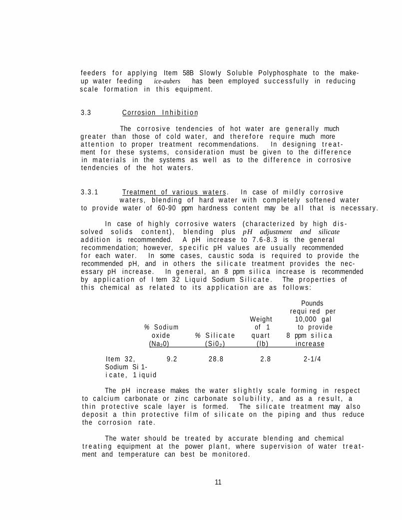
In case o f h i g h l y c o r r o s i v e wa te rs ( c h a r a c t e r i z e d by h igh d i s so lved s o l i d s c o n t e n t ) , b l e n d i n g p lus pH adjustment and silicate a d d i t i o n is recommended. A pH increase to 7 . 6 - 8 . 3 is the genera l recommendat ion; however, s p e c i f i c pH va lues are u s u a l l y recommended f o r each w a t e r . In some cases, c a u s t i c soda is r e q u i r e d to p r o v i d e the recommended pH, and in o the rs the s i l i c a t e t rea tment p rov ides the necessary pH inc rease . In g e n e r a l , an 8 ppm s i l i c a inc rease is recommended by a p p l i c a t i o n of I tern 32 L i q u i d Sodium S i l i c a t e . The p r o p e r t i e s of t h i s chemical as r e l a t e d to i t s a p p l i c a t i o n are as f o l l o w s :
Pounds requi red per
Weight 10,000 gal % S o d i u m of 1 to p rov i de
ox ide % S i l i c a t e q u a r t 8 ppm s i l i c a (Na20) (S i0 2 ) ( l b ) inc rease
I tem 32 , 9 .2 28 .8 2 .8 2-1 /4 Sodium Si 1-i c a t e , 1 i q u i d
The pH increase makes the wa te r s l i g h t l y sca le fo rm ing in respec t to c a l c i u m carbonate or z i n c carbonate s o l u b i l i t y , and as a r e s u l t , a t h i n p r o t e c t i v e sca le l a y e r i s formed. The s i l i c a t e t rea tmen t may a l s o d e p o s i t a t h i n p r o t e c t i v e f i l m o f s i l i c a t e on the p i p i n g and thus reduce the c o r r o s i o n r a t e .
The wate r shou ld be t r e a t e d by accu ra te b l e n d i n g and chemical t r e a t i n g equipment a t the power p l a n t , where s u p e r v i s i o n o f water t r e a t ment and temperature can best be m o n i t o r e d .
11

3.3.2 Required cor ros ion t e s t i n g . Corros ion tes te rs provided by the I l l i n o i s State Water Survey s h a l l be i n s t a l l e d to moni tor
the c ond i t i on or cor ros ion of the co ld and hot water d i s t r i b u t i o n p i p i n g . The t e s t i n g method used s h a l l be the ASTM D2688 Method C (ISWS), as descr ibed in ASTM Standards, Par t 23 , Nov. 1971 . Per iod ic removal of i nse r t s and measurement of the co r ros ion ra te w i l l d i sc lose the need f o r t reatment ad justment .
3.3.3 Corros ion r e s i s t a n t m a t e r i a l s . Al though chemical t reatment is o f t en the best s o l u t i o n to a co r ros ion problem, change
to more corrosion resistant materials may prove to be the most economical s o l u t i o n . This is p a r t i c u l a r l y t r ue where the co r ros ion problem is conf ined to a small sec t ion of a large water system.
In o ther words, i t would be c o s t l y to prov ide spec ia l t reatment of the water in a large system not r e q u i r i n g t h i s t reatment j u s t to co r rec t a co r ros ion problem in a small s e c t i o n .
I n s t a l l a t i o n of the wrong p ip i ng or equipment ma te r ia l f o r the p a r t i c u l a r water supply may be the reason f o r co r ros i ve f a i l u r e . Reference to a State Water Survey Repr int 115, "Materials Selection for Piping in Chemically Treated Water Systems," by R. W. Lane and C. H. Ne f f , may be h e l p f u l in a i d i n g s e l e c t i o n of the r i g h t ma te r i a l f o r a p a r t i c u l a r water supply .
3.3.4 Hot water tank l i n i n g . Hot water generators and storage tanks should be coated p e r i o d i c a l l y w i t h a cement type
coating, such as P re -Kre te * . Manholes should be provided f o r inspect i o n as we l l as a p p l i c a t i o n of a c o a t i n g .
3.4 Cathodic P ro tec t i on f o r Elevated Tanks
Cathodic p r o t e c t i o n may prove to be the most economical s o l u t i o n to some cor ros ion problems. Cathodic p r o t e c t i o n is a process i n vo l v i ng the use of an impressed cu r ren t on an e lec t rode to make the equipment metal the pro tec ted cathode. In e levated storage tanks, where low v e l o c i t y cond i t ions e x i s t , chemical t reatment methods f o r i n h i b i t i n g cor ros ion are genera l l y e f f e c t i v e . By p roper l y spacing e lec t rodes and by apply ing adequate c u r r e n t , ca thod ic p r o t e c t i o n has proven e f f e c t i v e i n i n h i b i t i n g .cor ros ion below the water l e v e l . Pa in t i ng i s s t i l l necessary; however, less f requent p a i n t i n g and more complete cor ros ion
*A low so iub le cement base tank l i n i n g mate r ia l f o r a p p l i c a t i o n to tanks used f o r hot or co ld wa te r , as formulated by Pocono F a b r i c a t o r s , I n c . , East St roudsburg, Pennsylvania 18301, and app l i ed by Andee Bo i l e r and Welding Co. , 7649 S. State S t . , Chicago, I l l i n o i s 60619, and o the rs .
12
i n h i b i t i o n is a t ta ined because " h o l i d a y s " in the pa in t f i l m (which p r a c t i c a l l y always e x i s t ) are prevented from cor rod ing by a p p l i c a t i o n o f ca thod ic p r o t e c t i o n .
In e levated tanks , the e lec t rodes are destroyed dur ing w i n t e r f r eez ing c o n d i t i o n s , but dur ing t h i s season of the year the temperature is so low tha t cor ros ion rates are min ima l . This is t rue because c o r r o s i o n , l i k e most chemical r e a c t i o n s , proceeds at a much slower ra te at lower temperatures. By i n s t a l l a t i o n of e lec t rodes in the spr ing and by c lose superv is ion to prov ide the recommended amperage read ings, ca thod ic p ro tec t i on has been found e f f e c t i v e in i n h i b i t i n g cor ros ion in e levated tanks .
Amperage readings should be reported weekly in the b o i l e r con t ro l repor t submit ted to the State Water Survey.
3.5 Gadgets
Gadgets (or e l e c t r i c a l , magnet ic, o r " c a t a l y t i c " devices) c la im ing immunity from scale and co r ros ion problems are c o n t i n u a l l y appearing on the market. Sale of these devices is mainly d i r e c t e d toward the householder, but uninformed i n s t i t u t i o n a l personnel can a lso be duped.
One should not be deceived by the salesman who o f f e r s the "gadget " f r e e - o f - c h a r g e . Such f ree i n s t a l l a t i o n s may be done simply as a sales means, so the salesman may t e l l h is next prospect tha t the State or University is using the i tem. This i m p l i c a t i o n of endorsement could then r e f l e c t adversely on the State i f the "gadget" proves u n s a t i s f a c t o r y . The claims f o r these dev ices , o f ten supported by t e s t i m o n i a l s , s t a t e t h e i r e f f ec t i veness is due to c a t a l y s i s , magnetism, e l e c t r o n i c s , r ad i a t i o n , and o ther hocus pocus, but present no q u a n t i t a t i v e data supported by s c i e n t i f i c f a c t . The I n te r -Soc ie t y Corrosion Committee of the Elect rochemical Society recommends "extreme caut ion in the a p p l i c a t i o n of devices f o r con t ro l o f cor ros ion and sca l i ng that are charac te r i zed by supposed opera t ion w i thou t any apparent basis of sound s c i e n t i f i c p r i n c i p l e s and f o r which no adequate eng ineer ing performance data are a v a i l a b l e . "
13

4. BOILER FEEDWATER TREATMENT
Twenty to t h i r t y years ago or longer , i n t e rna l b o i l e r feedwater t reatment chemicals (soda ash, s t a r c h , t a n n i n , e t c . ) were app l ied d i r e c t l y to the b o i l e r and the b o i l e r i t s e l f was used as a so f t ene r . In these low heat re lease b o i l e r s , scale fo rmat ion was reduced to a s u f f i c i e n t degree tha t r e l a t i v e l y t r o u b l e - f r e e opera t ion r e s u l t e d .
The modern b o i l e r , w i t h water w a l l s and smal ler diameter tubes, employs h igher heat t r a n s f e r rates and is not designed fo r handl ing feedwaters o f high suspended s o l i d s con ten t . There fo re , h igh q u a l i t y make-up water of minimum hardness, suspended mat te r , and d isso lved mineral content is requi red f o r e f f i c i e n t opera t ion and minimum maintenance.
4.1 External Sof ten ing
In 1949, make-up water of high hardness content was employed in 18 of the 36 high pressure State I n s t i t u t i o n a l power p l a n t s . Since tha t date ex te rna l so f ten ing equipment has been i n s t a l l e d in a l l p l a n t s . The two common methods of so f t en ing are l ime-soda ash so f ten ing and ion exchange (usua l l y sodium z e o l i t e ) s o f t e n i n g . Sodium z e o l i t e so f t en ing is gene ra l l y employed s ince i t is the s imp les t and the leas t expensive method of s o f t e n i n g .
4 .1 .1 Lime-soda ash s o f t e n i n g . In t h i s method of s o f t e n i n g , l ime and soda ash react w i t h b icarbonate and non-carbonate hardness
causing p r e c i p i t a t i o n of hardness and reduc t ion in e f f l u e n t hardness and a l k a l i n i t y , as f o l l o w s :
Ca(0H)2 + Ca(HC03)2 → 2CaC03↓ + 2H20
Ca(0H)2 + MgS04 + Na2C03 → CaCO3↓ + Mg(0H)2↓ + Na2S04
Cold l ime and soda so f ten ing is o f t e n p rac t i sed to reduce hardness and a l k a l i n i t y , and to s imul taneously c l a r i f y wa te r , f o r an e n t i r e i n s t i t u t i o n or c i t y ; t h i s process usua l l y is employed to reduce hardness only to the 60-120 ppm l e v e l . Hot lime and soda so f ten ing (210-250 F) is employed to reduce hardness to the 0-20 ppm l e v e l . It a l so reduces a l k a l i n i t y as we l l as hardness, and causes d isso lved s o l i d s reduct ion in some wa te rs , thus p r o v i d i n g high q u a l i t y make-up f o r steam produc t ion w i t h use of low cost chemica ls . The main disadvantages of the method are the maintenance problems involved in keeping the equipment c lean and in good opera t ing c o n d i t i o n , and the cons iderable e f f o r t requ i red in con t ro l o f the t rea tment .
14

4 .1 .2 Ion exchange s o f t e n i n g . Sodium z e o l i t e s o f t e n i n g , a l s o known as ion exchange, may be d e f i n e d as a process employ ing an
i n s o l u b l e r e a c t i v e m a t e r i a l ( r e s i n o r z e o l i t e ) capable o f i n t e r c h a n g i n g ions combined w i t h the m a t e r i a l , f o r ions in the w a t e r . T e c h n i c a l l y the ion exchanger now g e n e r a l l y used is not z e o l i t e (a s y n t h e t i c or n a t u r a l sodium a l u m i n o - s i l i c a t e ) but r a t h e r an o r g a n i c ion exchange r e s i n wh ich r e t a i n s i t s porous s t r u c t u r e d u r i n g the wa te r t r e a t i n g p rocess . These ion exchange r e s i n s are much more s t a b l e and have much h i g h e r c a p a c i t i e s than the z e o l i t e s . Hardness (as ca l c i um and magnesium b i c a r b o n a t e ) is exchanged w i t h sodium ions in the ion exchanger , and c a l c i u m and magnesium ions are l e f t in the exchanger as f o l l o w s :
Ca(HC03 )2 + Na2Ex → CaEx + 2NaHC03
In r e g e n e r a t i o n , the ca l c i um is rep laced by sodium ions in the s a l t and ca l c i um c h l o r i d e i s d i scha rged to was te :
CaEx + 2NaCl → Na2Ex + CaCl2
I n o rde r f o r t h i s process t o o p e r a t e e f f i c i e n t l y , suspended m a t t e r such as i r o n shou ld be removed by backwashing f rom the bed be fo re s a l t is a p p l i e d f o r r e g e n e r a t i o n ; then a f t e r r e g e n e r a t i o n , the c a l c i u m c h l o r i d e i s t ho rough l y r i n s e d f rom the z e o l i t e . I t i s a l s o most impor tan t t h a t the ion exchanger not be opera ted beyond i t s c a p a c i t y , s i nce hard wa te r may then be i n t r o d u c e d i n t o the b o i l e r .
Since many w a t e r s , p a r t i c u l a r l y s u r f a c e w a t e r s , vary i.n ha rdness , f r e q u e n t t e s t i n g o f the e f f l u e n t i s necessary to de termine when regene r a t i o n i s necessary . The modern method i s to i n s t a l l m o n i t o r i n g equipment wh ich c o n t i n u a l l y ana lyzes the s o f t e n e r e f f l u e n t f o r hardness c o n t e n t and e i t h e r opera tes an a la rm when t he s o f t e n e r is exhausted or a u t o m a t i c a l l y conve r t s the o p e r a t i o n t o ano the r s o f t e n e r and i n i t i a t e s r e g e n e r a t i o n o f the exhausted s o f t e n e r .
4.2 Condensate Co r ros ion Con t ro l
S ince many I l l i n o i s wa te rs are h i g h i n a l k a l i n i t y , r e d u c t i o n in hardness by z e o l i t e s o f t e n i n g may not be the on l y e x t e r n a l t r ea tmen t r e q u i r e d . The z e o l i t e s o f t e n i n g process removes hardness f rom the wa te r but does no.t remove a l k a l i n i t y .
Make-up wa te r w i t h h igh a l k a l i n i t y i n the form o f b i c a r b o n a t e and c a r b o n a t e , wh ich decompose to re l ease carbon d i o x i d e to the s team, r e s u l t s i n the f o r m a t i o n o f ca rbon i c a c i d i n the condensate . Th is causes c o r r o s i o n of s t e e l r e t u r n l i n e s . Th i s c o r r o s i o n may, be p reven ted by removal o f carbon d i o x i d e e x t e r n a l l y be fo re i t can e n t e r the b o i l e r , o r b y i n t e r n a l t r ea tmen ts w i t h n e u t r a l i z i n g o r f i l m i n g chem ica l s .
15
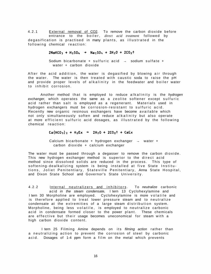
4 .2 .1 External removal of CO2. To remove the carbon d iox ide before entrance to the b o i l e r , direct acid treatment fo l lowed by
d e g a s i f i c a t i o n is p rac t i sed in many p l a n t s , as i l l u s t r a t e d in the f o l l o w i n g chemical r e a c t i o n :
Sodium b icarbonate + s u l f u r i c ac id → sodium s u l f a t e + water + carbon d iox ide
A f t e r the ac id a d d i t i o n , the water is degas i f i ed by b lowing a i r through the wa te r . The water is then t r ea ted w i t h caus t i c soda to ra i se the pH and prov ide proper l eve l s of a l k a l i n i t y in the feedwater and b o i l e r water t o i n h i b i t c o r r o s i o n .
Another method t h a t is employed to reduce a l k a l i n i t y is the hydrogen exchanger, which operates the same as a z e o l i t e so f tener except s u l f u r i c ac id ra the r than s a l t is employed as a regenerant . Ma te r i a l s used in hydrogen exchangers must be c o r r o s i o n - r e s i s t a n t to s u l f u r i c a c i d . Recently new organic resinous exchangers have become a v a i l a b l e which not only s imul taneously sof ten and reduce a l k a l i n i t y but a l so operate at more e f f i c i e n t s u l f u r i c ac id dosages, as i l l u s t r a t e d by the f o l l o w i n g chemical r e a c t i o n :
Calcium b icarbonate + hydrogen exchanger → water + carbon d iox ide + calc ium exchanger
The water must be passed through a degasser to remove the carbon d i o x i d e . This new hydrogen exchanger method is super io r to the d i r e c t ac id method s ince d isso lved s o l i d s are reduced in the process. Th is type of s o f t e n i n g - d e a l k a l i z i n g system i s being i n s t a l l e d a t f i v e S ta te I n s t i t u t i o n s , J o l i e t P e n i t e n t i a r y , S t a t e v i l l e P e n i t e n t i a r y , Anna Sta te H o s p i t a l , and Dixon Sta te School and Governor 's State U n i v e r s i t y .
4 .2 .2 I n te rna l n e u t r a l i z e r s and i n h i b i t o r s . To neutralize carbonic ac id in the steam condensate, I tern 13 Cyclohexylamine and
I tern 30 Morphol ine are employed. Cyclohexylamine is more v o l a t i l e and is t he re fo re app l ied to t r e a t lower pressure steam and to n e u t r a l i z e condensate at the e x t r e m i t i e s of a la rge steam d i s t r i b u t i o n system. Morpho l ine , being less v o l a t i l e , is employed to n e u t r a l i z e carbonic ac id in condensate formed c loser to the power p l a n t . These chemicals are e f f e c t i v e but t h e i r usage becomes uneconomical f o r steam w i t h a h igh carbon d iox ide con ten t .
I tern 25 F i lming Amine depends on i t s filming action r a the r than a n e u t r a l i z i n g ac t i on to prevent the co r ros ion of s tee l by carbonic a c i d . Dosages of 1-4 ppm form a f i l m on the metal which prevents
16

carbonic ac id a t t a c k . ( I t is a lso reported to prevent co r ros ion by d isso lved oxygen.) Bo i l e r carryover is reported to cause d i s r u p t i o n of the f i l m and a reduct ion in cor ros ion i n h i b i t i o n .
4 .2.3 Condensate cor ros ion t e s t i n g . Corrosion t e s t i n g in the condensate re tu rn l ines to determine the need f o r condensate
t reatment or the need f o r t reatment adjustment is advocated. NDHA type t es te r s (ASTM D2688 Method A, descr ibed in ASTM Standards Part 23, Nov. 1971) are supp l ied regu la r l y by the State Water Survey, and cont inuous mon i to r ing is thus p rov ided .
4 .3 Dissolved Oxygen Removal in Feedwater Heat ing
Dissolved oxygen removal to prevent co r ros ion of the b o i l e r and connect ing systems is essen t i a l in avo id ing ser ious metal de te r i o r a t i o n in power p lan t systems. E f f i c i e n t removal is usua l l y obta ined in the feedwater hea te r , and res idua] oxygen is reacted w i t h post chemi ca l feed of sodium s u l f i t e to reduce d isso lved oxygen content to minimal l e v e l s . Moni tor ing the feedwater heater opera t ion is t he re fo re an important phase of power p lan t ope ra t i on .
In most of the modern types of deaera tors , water f a l l s in d rop le ts through a r i s i n g cu r ren t of steam under pressure and a i r is vented out the top of the heater . An increase in the d a i l y sodium s u l f i t e dosage may i nd i ca te tha t the feedwater heater is not deaerat ing the water p rope r l y . Perhaps i n s u f f i c i e n t steam is being app l ied to heat the feedwater, or the vent may be p a r t i a l l y c losed , or the feedwater may be by-passing the heater or the t rays w i t h i n the heater .
When the e f f i c i e n c y of deaevation is quest ioned, reference should be made to the f o l l o w i n g c h a r t , which has been taken from the steam t a b l e s :
Feedwater heater Feedwater heater steam gauge pressure o u t l e t temperature
(ps ig) (°F)
0 212 1 215.3 2 218.5 3 221.5 4 224.4 5 227.1 6 229.8 7 232.3 8 234.8 9 237.1
10 239.4
17

The p r e s s u r e and t e m p e r a t u r e shou ld c o r r e s p o n d ; f o r examp le , t h e t empera tu re shou ld be 227 F at 5 p s i g p r e s s u r e . A t e m p e r a t u r e below 227 F, say 222 F at 5 p s i g steam p r e s s u r e , wou ld be ev idence o f a i r b i n d i n g o r i n s u f f i c i e n t v e n t i n g . I n o t h e r w o r d s , a i r , wh ich i s a t a lower t empe ra tu re than s team, i s be ing r e t a i n e d in the h e a t e r . The ven t shou ld then be checked to see t h a t p rope r v e n t i n g is be ing o b t a i n e d . I f v e n t i n g appears p rope r and good d e a e r a t i o n i s s t i l l no t be ing o b t a i n e d , an i n s p e c t i o n shou ld be made o f the h e a t e r i n t e r n a l s t o de te rm ine i f t he t r a y s o r sprays r e q u i r e c l e a n i n g o r r e p a i r .
4 . 4 I n t e r n a l o r Pos t -Chemica l T rea tment
Proper s l udge c o n d i t i o n i n g , s o f t e n i n g , and c o r r o s i o n c o n t r o l a re i m p o r t a n t f e a t u r e s of e f f e c t i v e internal or post-chemical treatment. E x t e r n a l s o f t e n i n g shou ld remove a l l b u t p o s s i b l y 0 . 0 - 2 ppm h a r d n e s s , bu t t h i s amount o f hardness can cause a p p r e c i a b l e s c a l e f o r m a t i o n in the modern h i g h hea t r e l e a s e b o i l e r . I tern 1C, IE or IF Organ ic Blend c o n t a i n i n g l i g n o s u l f o n a t e is a p p l i e d a t a 2-8 ppm dosage f o r the purpose o f c o n d i t i o n i n g the s ludge ( p r e c i p i t a t e d hardness) s o t h a t i t has l ess tendency t o s t i c k t o the b o i l e r m e t a l . U s u a l l y a minimum of 250 ppm p h e n o l p h t h a l e i n (P) a l k a l i n i t y is adequa te t o i n h i b i t c o r r o s i o n i n t h e b o i l e r and t o comple te t he w a t e r s o f t e n i n g r e a c t i o n . S u f f i c i e n t phosphate (PO4) i s a p p l i e d t o i n s u r e comple te p r e c i p i t a t i o n o f hardness w h i c h i s then d i s p e r s e d as c a l c i u m phosphate s l u d g e . Maintenance o f a s u l f i t e (SO3) r e s i d u a l i nsu res the absence o f oxygen i n the b o i l e r and t he i n h i b i t i o n o f c o r r o s i o n .
I n h i b i t i o n o f c a u s t i c e m b r i t t l e m e n t i s a t t a i n e d b y m a i n t a i n i n g 40 ppm sodium n i t r a t e (as NO3) and 100 ppm of I tem 1C, IE or IF Organ ic Blend i n the b o i l e r w a t e r . T h i s i s t h e gene ra l method employed; however , t h i s i s not necessary a t some i n s t i t u t i o n s because t he feedwa te r may be h i g h enough in s u l f a t e c o n t e n t to meet the recommended ASME s u l f a t e - a l k a l i n i t y r a t i o .
C h e l a n t s , such as I tern 68 (EDTA) , the sodium s a l t of e t h y l e n e d i a m i n e t e t r a a c e t i c a c i d and I tern 93 (NTA) , t h e t r i s o d i u m s a l t o f n i t r i l o a c e t i c a c i d a r e be ing employed t o t r e a t b o i l e r wa te r because o f t h e i r d e s i r a b l e p r o p e r t y o f d i s s o l v i n g ha rdness . These t r e a t m e n t s a r e e x p e n s i v e , p a r t i c u l a r l y because o f the h i g h dosage o f 10 p a r t s r e q u i r e d f o r each 1 p a r t o f ha rdness . C o n s e q u e n t l y , c h e l a n t t r e a t m e n t must be c o n s i d e r e d a supp lementa l t r e a t m e n t to be employed w i t h m in ima l hardness make-up produced b y e f f i c i e n t e x t e r n a l s o f t e n i n g . Che lan ts r e a c t w i t h d i s s o l v e d oxygen and a re rendered i n e f f e c t i v e , t h e r e f o r e they must be f ed f o l l o w i n g the feedwa te r h e a t e r o r f o l l o w i n g s u l f i t e t r e a t m e n t . Che lan ts can a l s o cause c o r r o s i o n o f b o i l e r equ ipment i f f ed i n excess and must t h e r e f o r e be f ed th rough a s t a i n l e s s s t e e l q u i l l i n t o t h e f e e d w a t e r f l o w and t h e f eed must be a c c u r a t e l y c o n t r o l l e d . S ince t h e r e has no t been a s a t i s f a c t o r y p l a n t c o n t r o l t e s t method deve loped f o r c h e l a n t s , phosphates a r e a p p l i e d i n c o n j u n c t i o n w i t h the c h e l a n t s , then the knowledge o f phosphate t e s t r e s u l t s and dosage requ i remen ts a r e used e f f e c t i v e l y t o m o n i t o r t he c h e l a n t t r e a t m e n t .
18

Scal ing in package h igh-heat release b o i l e r s is becoming an increas ing problem, so a t t e n t i o n has had to be d i r e c t e d to the cont inuous product ion of abso lu te l y zero so f t water make-up and feedwater. Also moni tor ing of r e tu rn condensate f o r hardness and d isso lved s o l i d s contaminat ion is extremely important in c o n t r o l l i n g sca le , co r ros ion and steam p u r i t y . With t h i s c lose con t ro l and che lant t reatment to react w i t h res idua l hardness i t i s f e l t tha t the prevent ion o f scale fo rmat ion in package b o i l e r s may be kept under proper c o n t r o l .
4.5 Condensate Pur i t y
Mon i to r ing the condensate re tu rn f o r hardness or d isso lved so l i ds contamination i s a lso important in ma in ta in ing b o i l e r c l e a n l i ness or freedom from scale f o rma t i on . The most common source of hardness contaminat ion is from leak ing steam c o i l s in a domestic hot water hea te r . Evidence of hardness in the condensate r e t u r n , h igher than normal b o i l e r phosphate requi rements, and lower than normal d a i l y make-up gal lonage are c lues t ha t hard water contaminat ion is occu r r i ng and should be e l im ina ted as soon as poss ib le .
There have a l so been cases of detergent so lu t i ons from dishwashers contaminat ing condensate re turns and causing b o i l e r foaming. Such f o u l ing can be detected by measuring the e l e c t r i c a l c o n d u c t i v i t y of the condensate. Contaminated condensate w i l l have a h igher c o n d u c t i v i t y reading than pure condensate.
4.6 Blowdown Control
The success of b o i l e r water t reatment is very dependent on accurate and adequate blowdown control. The accurate t e s t i n g of d isso lved so l i ds by e l e c t r i c a l c o n d u c t i v i t y measurement has been extremely he lp fu l i n a t t a i n i n g t h i s o b j e c t i v e .
The to le rance of the modern high heat re lease b o i l e r f o r suspended so l i ds is low; t he re fo re c lose a t t e n t i o n to suspended so l i ds content is necessary. Exce l len t co r ros ion i n h i b i t i o n in steam condensate l i nes is necessary so t ha t a minimum of co r ros ion products (suspended s o l i d s ) are brought back to the b o i l e r . Accumulation of suspended s o l i d s may occur in water w a l l s , and overheat ing w i l l cause metal f a i l u r e . Since blowdown of water wa l l s is not too e f f e c t i v e , the best p r a c t i s e is to l i m i t the amount of suspended matter (hardness sludge or co r ros ion products) en te r i ng the b o i l e r and to p e r i o d i c a l l y remove the b o i l e r from serv ice f o r examinat ion and more f requent washout.
4.7 Steam Pur ity
To cont inuous ly a t t a i n a proper high leve l of steam purity, the f o l l o w i n g f a c t o r s must be watched:
(a) Control of the b o i l e r P a l k a l i n i t y , suspended s o l i d s , and d isso lved s o l i d s as d i r ec ted in the p lan t con t ro l c h a r t s .
19

(b) Contro l o f o i l w i t h i n the s p e c i f i e d l i m i t s ( less than 7 ppm in the b o i l e r w a t e r ) .
(c) Contro l o f opera t ing b o i l e r va r i ab l es to avoid extremes and rapid changes in load and water l e v e l .
(d) Contro l of des ign , i n s t a l l a t i o n , and maintenance of b o i l e r i n t e rna l s and steam p u r i f y i n g equipment.
(e) Contro l o f ex te rna l so f tener opera t ion to main ta in hardness contaminat ion at a minimum l e v e l .
( f ) Contro l of condensate contaminat ion by mon i to r ing condensate and prevent ing the a d d i t i o n of foaming contaminants to the system.
Carryover cannot be t o l e r a t e d in the modern power p lan t because s o l i d s in the steam w i l l cause eros ion of t u r b i n e blades and co r ros ion of steam-using equipment, which may cause p lan t shut-downs or ser ious maintenance problems. I tern 1C Organic Blend app l ied in the 2-8 ppm dosage range genera l l y provides adequate an t i - f oam and c o n d i t i o n i n g of suspended matter to prevent foaming and car ryover of b o i l e r water .
Steam P u r i t y Analyzers are i n s t a l l e d in a l l the State p lan ts in which tu rb ine generators operate . These instruments are h e l p f u l in mon i to r ing p lan t opera t ing v a r i a b l e s , such as water l e v e l , b o i l e r load, water t reatment ,and blowdown, which may a f f e c t steam p u r i t y . An analyzer is a v a i l a b l e at the State Water Survey f o r use in those p lan ts not having one. The Steam P u r i t y Analyzer measures the d isso lved so l i ds in condensed steam by e l e c t r i c a l c o n d u c t i v i t y . I n te r fe rence due to amines in the steam is e l im ina ted in t h i s t e s t method.
Cor ros ion-eros ion of t u rb ine va l ves , nozzle r i n g s , and t u rb i ne casing may r e s u l t from high v e l o c i t y steam con ta in ing carbon d iox ide and mo is tu re . In p lan ts app ly ing sa tu ra ted steam to t u r b i n e s , i n s t a l l a t i o n of s t a i n l e s s s tee l nozzle and d i v e r s i o n r ings and i n s t a l l a t i o n of s t a i n l e s s s tee l s t r i p p i n g on the ins ide of the casing have been necessary. A p p l i c a t i o n of h igher amine t reatments has a lso been proven exper imen ta l l y to reduce t h i s c o r r o s i o n . Conversion to superheated steam has been arranged in the newer p lan ts and has prevented t h i s type o f c o r r o s i o n .
4.8 Role of Bo i l e r Operat ion
4.8.1 Operat ion schedu l ing . Just as ma in ta in ing proper b o i l e r water leve ls and schedul ing b o i l e r loads to prevent extreme f l u c t u
a t i ons in steam demand are important in p rov i d i ng high steam p u r i t y , b o i l e r c lean l iness can be improved by proper b o i l e r o p e r a t i o n .
20

I f sludge accumulations are noted in p a r t i c u l a r areas of the b o i l e r dur ing i n s p e c t i o n , increased blowdown should be app l ied at these l o c a t i o n s . I f the b o i l e r i s inadequately designed to t o l e r a t e minimal sludge concent ra t ions der ived from minimal hardness from the ex terna l so f ten ing system, or hardness or rus t contaminat ion from the re tu rn system, more f requent b o i l e r wash-outs and shor te r cont inuous runs must be scheduled.
4 .8 .2 Removal of b o i l e r from ope ra t i on . The proper procedure f o r the removal of a b o i l e r from opera t ion is of pr imary impor
tance. While the b o i l e r is in o p e r a t i o n , i t has the b e n e f i t o f c e r t a i n treatment and con t ro l procedures es tab l i shed to prevent the fo rmat ion of scale on the b o i l e r heat ing sur faces . However, i f the b o i l e r is removed from opera t ion improper ly , much of the good work of proper treatment and con t ro l can be undone.
During opera t ion the b o i l e r water contains suspended s o l i d s (or mud) which are held in suspension by c i r c u l a t i o n of the water and by the ac t i on of the t reatment . Unless the b o i l e r is p roper ly d ra i ned , these suspended s o l i d s may s e t t l e out on the b o i l e r surfaces and a i r dry as adherent depos i t s , sometimes requ i r i ng t u r b i n i n g of the b o i l e r tubes. In a d d i t i o n , unless the deposi ts are examined c a r e f u l l y , i t may be assumed i n c o r r e c t l y tha t they are scale formed dur ing o p e r a t i o n . This assumption could lead to unwarranted changes in the water t rea tment .
There fo re , in order to p roper ly judge the e f f ec t i veness of the water t reatment as we l l as to e l i m i n a t e unnecessary b o i l e r c l e a n i n g , great care must be taken in removal of the b o i l e r from o p e r a t i o n . The f o l l o w i n g procedure is recommended:
(a) A h a l f hour before shu t t i ng down a b o i l e r , a l t e r n a t e bottom and sur face blowdown, apply ing 5-second blows over 6 evenly spaced i n t e r v a l s .
(b) A f t e r f i r i n g is s topped, cont inue blowdown f o r longer per iods at leas t every hour, ma in ta in ing the normal opera t ing water leve l and rep lac ing much of the b o i l e r water w i t h hot feedwater.
(c) Continue t h i s procedure un t i 1 the b o i l e r is cool enough to open, then d ra in and f l u s h drums and wash down tubes w i t h a heavy stream of water from high pressure hoses. Residual sludge w i l l thus be kept we t , w i l l not be al lowed to dry on the hot tube su r faces , and w i l l be f lushed e f f e c t i v e l y from the b o i l e r .
I f i t is not convenient to wash out the b o i l e r immediately on d r a i n i n g , i t should be r e f i l l e d w i t h water because there may s t i l l be s u f f i c i e n t heat l e f t in the b o i l e r s e t t i n g to cause baking o f res idua l
21

sludge on the tubes. However, the b o i l e r should never be l e f t f i l l e d w i t h water fo r more than a few days w i t hou t tak ing proper measures to prevent cor ros ion and p i t t i n g .
4.9 Prevent ion of Corrosion in I d l e Bo i l e rs
Serious pitting corrosion of b o i l e r s ( cos t ing $10,000 or more f o r repa i rs ) has occurred dur ing out-of-service pe r i ods . This is a more ser ious problem now than ever before because b o i l e r s are c leaner , more f ree of scale and the re fo re have more exposed metal than in past years . A b o i l e r he ld h a l f f u l l of water f o r one to two weeks or more before opera t ion or f o l l o w i n g opera t ion may become s e r i o u s l y p i t t e d or corroded a t the water l i n e .
4 .9 .1 Storage method s e l e c t i o n . A b o i l e r may be s to red wet or d r y . I f recommended procedures are f o l l o w e d , r e s u l t s should be
equa l l y e f f e c t i v e . The dec is ion as to the method to use should depend on which method can be best adapted to the p a r t i c u l a r p lan t o p e r a t i o n .
Dry storage is the s implest and eas ies t procedure and the re fo re i s gene ra l l y p re fe r r ed i f p r a c t i c a l . However, dry s torage i s e f f e c t i v e only i f b o i l e r i n t e r n a l s are kept completely d ry . In case l i m i t e d leakage of stop and check valves is exper ienced, wet s torage methods may be a s o l u t i o n ; however, i f ove r f l ow ing is then exper ienced, t h i s method of storage w i l l a lso be i n e f f e c t i v e and valve repa i r or rep lacement is the only s o l u t i o n .
There are two methods of wet storage depending on whether the b o i l e r is s tored w i t hou t c lean ing (Method A) or is s to red a f t e r c lean ing or when empty (Method B) .
Wet storage is required f o r b o i l e r s w i t h superheaters s ince superheater tub ing cannot be dra ined d ry . In a memorandum dated A p r i l 22, 1968, recommendations were given to f i l l superheater tub ing completely f u l l and to prov ide f o r complete removal of t rea ted water before s t a r t - u p . Since these procedures were recognized to be d i f f i c u l t o p e r a t i o n s , i nco rpo ra t i on of amine t reatment ( I tem 13 Cyclohexylamine or I tern 25 F i lming Amine) has been recommended to prov ide d i s t i l l a t i o n o f these a l k a l i n e or f i l m - f o r m i n g v o l a t i l e chemicals i n t o the superheater tub ing to prov ide the necessary cor ros ion i n h i b i t i o n .
Wet storage may be p re fe r red in e l e c t r i c generat ing p lan ts in which rap id s t a r t - u p is requi red in case of an emergency. Bo i l e rs s tored wet requ i re only d ra in ing to 1 /4 l e v e l , then f i l l i n g to opera t ing leve l before s t a r t i n g o p e r a t i o n . Bo i l e r s s to red dry requ i re c los ing o f manholes and valves and f i l l i n g before s t a r t i n g o p e r a t i o n .
22

4 . 9 . 2 Dry method. The f o l l o w i n g procedures should be app l ied in s t o r i n g b o i l e r s i n t e r n a l l y by the dry method.
(1) Drain bo i i le r .
(2) Dry thorough ly , i nc lud ing a l l par ts where pockets of water might be t rapped. A l i g h t wood f i r e or c i r c u l a t i on of a i r may be necessary to ob ta in complete dryness.
(3) Open a l l manholes, blowdown va l ves , e t c . , which w i l l a l low f ree c i r c u l a t i o n o f a i r through the b o i l e r drum and tubes.
(4 ) E l im ina te a l l water d r i p p i n g i n t o drum or tubes.
(5) Swab out a l l tubes which do not d ra in d r y . Some b o i l e r s have connect ing tubes which curve downward between the top two or three drums. These tubes p a r t i c u l a r l y requ i re a t t e n t i o n in removal o f a l l mo is tu re .
(6) Check b o i l e r s weekly to see tha t they are completely d r y .
4 .9 .3 Wet Method A. The f o l l o w i n g procedures should be app l ied f o r wet storage when the b o i l e r is not to be cleaned i n t e r n a l l y .
(1) Blowdown b o i l e r thorough ly .
(2) At least 15 minutes before b o i l e r comes o f f the l i n e , add the f o l l o w i n g chemicals:
(a) 6 lb of sodium s u l f i t e per 1000 gal of b o i l e r capaci ty (average b o i l e r capac i ty is 4000-6000 g a l ) .
(b) 1 lb of organic blend per 1000 gal of b o i l e r capaci t y .
(c) S u f f i c i e n t caus t i c soda (about 8 lb per 1000 gal of b o i l e r capac i ty ) to produce a P a l k a l i n i t y reading of 1000-1700 ppm.
(d) Only f o r boiler with superheater: 1-1/2 lb of Itern 13 Cyclohexylamine or 1/2 lb of Itern 25 Fi lming Amine per 1000 gal of b o i l e r capac i t y .
(3) Watch b o i l e r c a r e f u l l y f o r foaming tendencies and take i t o f f the l i ne in case foaming develops.
23

(4) A f t e r t a k i n g b o i l e r o f f the l i n e , f i l l b o i l e r t o t o p , o v e r f l o w i n g ven ts o r s a f e t y va l ves to make sure complete f i l l i n g i s accomp l i shed . I t i s e s s e n t i a l t h a t b o i l e r
be f i l l e d comp le te l y and t h a t no a i r pockets be p r e s e n t . Close a l l va l ves except those on the top o f the b o i l e r . P lace a cap on the h i gh wa te r w h i s t l e when w a t e r f l o w s o u t .
(5) When b o i l e r i s c o m p l e t e l y f u l l , c l o s e a l l va l ves i n o rde r t o sea l b o i l e r f rom p o s s i b l e en t r ance o f a i r .
(6) I f wa te r l e v e l f a l l s d u r i n g the s t o r a g e p e r i o d , add more wa te r and chemica ls ( i f need i s i n d i c a t e d by t e s t ) to keep b o i l e r c o m p l e t e l y f i l l e d . A smal l drum f i l l e d w i t h wa te r and connected to the steam t a k e - o f f t a p , v e n t , o r s a f e t y v a l v e c o n n e c t i o n may be i n s t a l l e d to p r o v i d e make-up w a t e r in case o f leakage and to ope ra te as an i n d i c a t o r o f the b o i l e r wa te r l e v e l .
(7) Tes t b o i l e r wa te r f o r p roper sodium s u l f i t e and P a l k a l i n i t y c o n t e n t each 30 days.
(a) Recommended minimum s u l f i t e r e s i d u a l (SO3) is 50 ppm.
(b) Recommended minimum P a l k a l i n i t y is 1000 ppm.
(c) Add more chemica l as needed to meet the above minimum recommendat ions.
(8) Be fo re s t a r t i n g o p e r a t i o n , d r a i n b o i l e r con ten t s t o 1 / 4 drum l e v e l , remove cap f rom h i g h water w h i s t l e , and then f i l l the b o i l e r w i t h feedwate r t o o p e r a t i n g l e v e l .
4.9.4 Wet Method B. The f o l l o w i n g procedures shou ld be a p p l i e d f o r wet s t o r a g e a f t e r b o i l e r has been c leaned o r i f b o i l e r i s empty.
(1) Prepare a s o l u t i o n of the chemica ls (a -c and d w i t h supe rhea te rs ) d e s c r i b e d under s t e p (2) in s e c t i o n 4 . 9 . 3 .
(2) Feed the above s o l u t i o n c o n t i n u o u s l y w i t h the b o i l e r feedwater be ing a p p l i e d to the b o i l e r . I t is very important that a uniform concentration of this solution be provided throughout the boiler.
(3) For boilers with superheaters, s t a r t a l i g h t wood f i r e t o p r o v i d e s u f f i c i e n t steam t o v o l a t i l i z e the amine over i n t o the s u p e r h e a t e r . Steam shou ld issue f rom
24

the superheater vent . A f t e r the f i r e has subs ided, it is essential that the boiler be filled completely and that no air pockets be present.
(4) During f i l l i n g , c lose a l l valves except those on the top of the b o i l e r . Place a cap on the high water w h i s t l e when water f lows o u t .
(5) When b o i l e r is completely f u l l , c lose a l l valves in order to seal b o i l e r from poss ib le entrance of a i r [see step (3) above fo r b o i l e r s w i t h superhea te rs ] .
(6) During the storage p e r i o d , keep the b o i l e r completely f u l l by adding more water and chemicals ( i f i nd i ca ted by tes ts ) as descr ibed in steps (6) and (7) in sec t ion 4 . 9 . 3 . A l i g h t wood f i r e w i l l l i k e l y be requi red to provide c i r c u l a t i o n and un i form d i s t r i b u t i o n o f additional chemicals. Test the b o i l e r water at d i f f e r e n t loca t ions in the b o i l e r to determine the un i f o rm i t y of chemical t reatment and the need fo r f u r t h e r c i r c u l a t i o n w i t h i n the b o i l e r .
(7) Before s t a r t i n g o p e r a t i o n , d ra in b o i l e r contents to 1/4 drum l e v e l , remove cap from high water w h i s t l e , and then f i l l the b o i l e r w i t h feedwater to opera t ing l e v e l .
4 .9 .5 Supplemental storage recommendations. In add i t i on to proper i n te rna l methods o f s to rage , c lean ing o f a l l soot , f l y ash,
and s lag from fire-side surfaces is necessary. I d le b o i l e r s have a tendency to sweat ( p a r t i c u l a r l y i f wet s torage methods are app l ied) under adverse atmospheric c o n d i t i o n s . Combination of moisture w i t h such deposi ts w i l l form ac ids , and rap id co r ros ion can be expected.
A l s o , dur ing a pe r i od i c b o i l e r c l e a n i n g , painting of Apexior #1* on b o i l e r drum surfaces and on tube surfaces ( w i t h i n 1 foot or more of the drum) has been b e n e f i c i a l . Although any pa in t is only as good as the completeness of the c o a t i n g , t h i s p a r t i c u l a r pa in t has been he lp f u l in reducing p i t t i n g and cor ros ion. and is recommended as a supplementary a id in reducing c o r r o s i o n , p a r t i c u l a r l y in cases of cont inued ser ious cor ros ion problems.
4 .9 .6 Ou t -o f - se rv i ce b o i l e r records. I t i s requested tha t opera t ing engineers keep an accurate weekly record on the s ta tus of the
i n d i v i d u a l b o i l e r , to be recorded in the lower r ighthand corner of the present weekly r e p o r t . The weekly inspec t ion of each o u t - o f - s e r v i c e
*The Dampney Company, 85 Par is Street . , E v e r e t t , Massachusetts 02149
25

b o i l e r should inc lude the f o l l o w i n g :
Dry storage - Note whether the b o i l e r is complete ly dry in drums and tubes, p a r t i c u l a r l y tha t tubes which do not d ra in dry have been swabbed o u t . I f b o i l e r is not d r y , the wet cond i t i on should be co r rec ted and arrangements made to prevent f u r t h e r occurrences.
wet storage - Note tha t b o i l e r is completely full. If water loss has occu r red , f i n d reason and c o r r e c t . Test the P alkalinity and sulfite monthly and apply further treatment if necessary.
An example of the repor t submit ted would be:
Boi le rs P S03
#1 , 2, 6 - in se rv i ce #3 - wet storage 1200 70
1100 100 1100 90
#4 - dry storage #5 - dry storage
The b e n e f i t o f submi t t i ng these records w i l l be to c a l l everyone's a t t e n t i o n to the s ta tus of each i n d i v i d u a l b o i l e r so tha t the out-of-service boiler will not be allowed to stand half-full of water for periods longer than a few days.
4.10 E f fec t of Make-up, Blowdown, and B o i l e r E f f i c i e n c y on Treatment
The make-up wa te r , blowdown, and b o i l e r e f f i c i e n c y percentages are of i n t e r e s t in power p lan t o p e r a t i o n . For example, a water t r e a t ment program f o r a b o i l e r system employing a high make-up percentage must operate more e f f i c i e n t l y (produce lower hardness make-up) than one employing feedwater d i l u t e d w i t h a large percentage of condensate. Also f o r comparing t reatment e f f i c i e n c i e s , the percent blowdown c a l cu la ted f o r the d i f f e r e n t t reatments is important in dec id ing the most e f f i c i e n t t reatment . Fu r the r , the feedwater t reatment is an important f a c t o r in determining the degree o f t o t a l b o i l e r ope ra t i ng e f f i c i e n c y , and the b o i l e r e f f i c i e n c y c a l c u l a t i o n may in tu rn y i e l d a comparison in e f f ec t i veness of d i f f e r e n t methods of t reatment . Operat ion at m i n i mum make-up and blowdown and a high b o i l e r e f f i c i e n c y . a r e advocated f o r o v e r a l l h igh power p lan t e f f i c i e n c y .
4 .10.1 Ca lcu la t i ng percent make-up. The percentage of make-up water in the t o t a l feedwater e n t e r i n g the b o i l e r is o f i n t e r e s t
because it is a measure of the losses in the system and the consequent
26

loading and e f f i c i e n c y of the make-up water system. It may be ca l cu la ted from metered make-up water and steam f l o w as f o l l o w s :
Example:
Or, the percent make-up may be determined by ana lyz ing the f eed -water f o r c h l o r i d e or M a l k a l i n i t y ( i f no a l k a l i n e chemicals are app l ied to feedwater) and c a l c u l a t i n g as f o l l o w s :
Example: CI (feedwater) = 4; CI - (make-up) = 1 2
4 .10 .2 C a l c u l a t i n g percent blowdowh. The percentage of blowdown is important because it is a measure of the necessary losses
from the system to prevent excessive s o l i d s or depos i t accumulat ions. D i f f e r e n t methods of water t reatment requ i re d i f f e r e n t rates o f blow-down, so a comparison of blowdown rates is necessary to eva luate t rea tments . A f t e r ana lyz ing the feedwater and b o i l e r water f o r c h l o r i d e con ten ts , the percentage of blowdown is ca l cu la ted as f o l l o w s :
Example: CI- ( feedwater) = 4; CI- ( b o i l e r water) = 200
4.10.3 B o i l e r e f f i c i e n c y . The b o i l e r e f f i c i e n c y provides an i n d i c a t i o n o f the opera t ing e f f i c i e n c y o f the b o i l e r i n respect t o
heat input and o u t p u t . The b o i l e r e f f i c i e n c y is ca l cu la ted as f o l l o w s :
27

in which
hg = enthalpy of steam at abso lu te steam pressure (obta ined from steam tab les )
t = feedwater heater temperature
Equiva lent evapora t ion = f a c t o r of evap x ac tua l evap
* Unit of fuel burned is lb of ooal, gal of oil, or cu ft of gas
Example:
The t o t a l BTU output = t o t a l steam generated m u l t i p l i e d by the f o l l o w i n g q u a n t i t y :
[ (hg from Steam Table 2, column hg at a pressure equal to opera t ing gauge pressure + 15) - (feedwater temperature - 3 2 ) ]
Example:
Steam pressure = 245 ps ig + 15 = 260 psia = 1201.5 ( f rom Steam Table 2)
Feedwater temperature = 235 F - 32 = 203
Steam Generated = 750,000 lb
Output = 750,000 x (1201.5 - 203) = 750,000 x 998.5 = 748,875,000 BTU's = 748.875 x 10⁶ BTU's
The t o t a l BTU input = t o t a l u n i t s of fue l burned m u l t i p l i e d by the BTU content per u n i t .
Assume a t o t a l BTU input of 1,000,000,000 or 1,000 x 106 BTU from burn ing 100,000 lbs coal at 10,000 BTU/lb or 10,000 therms of gas.
There fo re :
28
5. CLOSED HOT AND CHILLED WATER SYSTEMS AND TREATMENT
There is now a definite trend to employ hot water rather than steam for heating. The advantages are that more heat (BTU's) can be carried by hot water than by steam in the same sized pipe and no steam traps are required.
Years ago, the household hot water heating system consisted of piping and old style radiators with large sized passageways. Materials were steel, cast iron, and brass valves -- equipment in which water losses were not usually experienced. Present day hot water systems include thousands of feet of small diameter piping, hundreds of small control valves and temperature sensing devices, and dozens of pumps having mechanical seals; further, among these, many dissimilar metals are involved. Therefore more potential sources of water losses are present, and if make-up water usage is excessive, corrosion and scale may become a serious matter.
5.1 Kinds of Systems
There are various kinds of hot water heating systems, some fired and some unfired. These systems are all considered closed systems, but the more common are the unfired systems, some of which are heated by steam from steam boilers by means of heat exchangers, and others of which are heated by heat exchangers and separate HTW and MTW hot water generators. There are also closed chilled water systems for air conditioning, which are chilled by refrigerating systems having electrical or absorption (steam or hot water) power sources to provide the necessary cooling. Much of the following discussion concerns the unfired systems and particularly the hot water systems because there are so many of these, of all sizes, and because maintenance problems are generally more serious and require attention.
The HTW systems (pressurized hot water of above 350 F in temperature) are usually large systems supplying heat to an entire institution. Since the heating system is centralized in the power plant, proper and complete water treating facilities and control provide the necessary preventive maintenance. MTW systems (pressurized hot water of 225-350 F in temperature) are similar to the HTW systems but are operated at a lower temperature. Both systems, usually pressurized by nitrogen gas, are fired systems, which include hot water generators of considerably different internal design from steam boilers. These generators have no drums and are composed of few but long continuous water tube circuits, which completely cover the internal heating surfaces of the generator in order to derive efficient heat transfer and high boiler efficiency.
29

5.2 Treatment and Test ing of Closed Systems
Unf i red c losed systems should be expected to be r e l a t i v e l y f ree o f sca le and co r ros ion d i f f i c u l t i e s l a r g e l y because l i t t l e i f any make-up water should be requ i red f o r o p e r a t i o n . However, make-up requirements are gene ra l l y h igher than d e s i r e d , usua l l y because of mechanical seal and s p l i t - c a s e pump seal leakage, or because of poor design of inadequate s i z i n g of expansion tank systems. I f continued application of hard water is r e q u i r e d , ser ious scale d i f f i c u l t i e s may be expected in these systems. If a co r ros i ve water (one con ta in ing apprec iab le d isso lved s a l t s and oxygen) is app l ied con t i nuous l y , corrosion of the system a lso may be expected. A f t e r such sca le or co r ros ion d i f f i c u l t i e s have developed, the removal of the depos i ts i s usua l l y d i f f i c u l t and expensive.
Closed system equipment may be p ro tec ted from co r ros ion by app ly ing a co r ros ion i n h i b i t o r , such as I tern 70 Corrosion I n h i b i t o r Blend (chromate-soda ash) or I tern 62 Hot Water B o i l e r Blend ( n i t r i t e -bo rax ) . In i n i t i a l f i l l i n g of these systems, 4 1/2 lbs of Item 70/1000 gals volume is requ i red to prov ide 250 ppm Chromate (as Cr04) and 11 1/4 lbs of I tern 62/1000 gals volume is requ i red to prov ide 600 ppm N i t r i t e (as NO2) in the systems. By p e r i o d i c t e s t i n g of the i n h i b i t o r c o n c e n t r a t i o n , the b u i l d i n g engineer may c a l c u l a t e the water l o s s , c o r r e c t the leakage problem, and est imate the a d d i t i o n a l chemicals r e q u i r e d . The water loss may be est imated by c a l c u l a t i n g the percent o f i n i t i a l chemical concent ra t ion and then r e f e r r i n g to the char t below. The leakage is usua l l y too small to be detected by water meters , unless water a d d i t i o n is made by so leno id va lve c o n t r o l .
% of i n i t i a l Water loss concen t ra t ion (% of system volume)
100 0 95 6 90 12 85 17 80 22 75 30 70 37 65 46 60 55 55 64 50 72 45 83 40 94 35 108 30 122 25 143 20 163 15 190 10 230 5 300
30

Example:
If the chromate tested 300 ppm at the start of one month and tested only 200 ppm at the end of the month, the percent of initial concentration is calculated as follows:
Reference to the chart then shows:
67% = about 40% loss of system volume per month
Since a closed system is defined as one that loses less than 5% of its volume annually., (0.42%/month, 0.014%/day), this particular system is operating with too much loss, approximately 100 times too much. If this amount of loss had occurred in one year instead of one month, the percent loss would have been 3.3%, a satisfactory loss for a closed system.
To provide proper corrosion inhibition and control, monthly tests for chromate (minimum 250 ppm Cr04 or nitrite (minimum 600 ppm NO2) are recommended.
In all new installations, the State Water Survey has recommended the installation of a make-up water system , including an air gap, which prevents contamination of the potable water system by the chemicals used for treatment in the closed water system. If a Public Health approved make-up system (including an air gap) were not installed, contamination of the potable water system could occur whenever the closed system pressure exceeded the make-up water or potable water system pressure.
5.2.1 Source of leakage. In installations having the recommended make-up water systems isolated from the potable water system,
periodic testing (at least monthly) of the chromate content of the closed system water provides a check on the water loss or make-up water usage. If continued high chromate (Item 70) consumption is required (substantial monthly additions rather than annual additions) to maintain the recommended chromate test of 250+ ppm chromate (as Cr04 , it may be concluded that serious losses are occurring and that the causes of losses or leakage should be immediately corrected.
The losses are likely to be located at:
(a) Expansion tanks (b) Multiple make-up water connections
31

(c) Make-up s t a t i o n having f a u l t y v a l v i n g or design
(d) Ai r e l i m i n a t o r s
(e) Connections w i t h o the r p i p i n g systems
( f ) Pump seals
In the case of (e) above, passage of make-up water to consumptive usage in a domestic hot water system or in a coo l i ng tower can cause i n t r o d u c t i o n of hard water and d i sso lved oxygen con t i nuous l y . This may r e s u l t in ser ious scale fo rmat ion or c o r r o s i o n . A heat exchanger f o r hea t ing domestic hot water may develop a leak and cause t h i s cond i t i o n . I f the domestic hot water pressure is h igher than the c losed system pressure , f l o o d i n g of the c losed system may occur r e s u l t i n g in s i m i l a r bad e f f e c t s .
5 .2 .2 Cleaning c losed systems. The c lean ing of new c losed systems i s o f cons iderab le importance because the o r i g i n a l water f i l l
may be r e c i r c u l a t e d in these systems f o r months and is not rep laced. However, in once through and steam systems, the i n t r o d u c t i o n of new make-up wa te r , and in the case of steam systems, t r app ing and blowdown (or replacement) occur which prov ides cont inuous r i n s i n g and removal of suspended mat te r .
Cleaning w i t h caus t i c soda and t r i s o d i u m phosphate and thorough f l u s h i n g have been recommended in the s p e c i f i c a t i o n s ; however, the design o f these systems makes thorough, e f f i c i e n t c lean ing and r i n s i n g d i f f i c u l t . Black magnetic i ron ox ide o f t en scales o f f and may score mechanical s e a l s . The i n s t a l l a t i o n of t raps con ta in ing magnets is being considered as a s o l u t i o n t o t h i s problem.
5.3 HTW and MTW System Treatment
5 .3 .1 HTW system. Z e o l i t e sof tened make-up water is employed in the HTW or h igh temperature (above 350 F) hot water systems.
This water is then t r ea ted w i t h caus t i c soda to p rov ide a pH of 9 .5 -10 .5 and w i t h sodium s u l f i t e to prov ide a s u l f i t e t e s t of 50-100 ppm to con t ro l c o r r o s i v e tendencies. I t would be b e t t e r i f make-up water requirements f o r these systems conformed to the 0.014%/day genera l l y s p e c i f i e d f o r c losed systems; however, 0.1-0.5% (of the t o t a l system volume) make-up per day is the more normal requi rement . Da i l y t es t s are necessary to prov ide the exact water t reatment c o n t r o l r e q u i r e d .
Accurate co r ros ion t e s t i n g under measured f low cond i t i ons is prov ided by i n s t a l l i n g weighed p ipe n ipp les in a metered by-pass. The State Water Survey provides these specimens in order t ha t cont inuous mon i to r ing of the e f f ec t i veness of the t reatment may be ob ta i ned .
32

5.3.2 MTW system. For medium temperature (225-350 F) hot water systems, two methods of t reatment have been employed; namely,
the caus t i c s o d a - s u l f i t e t reatment of z e o l i t e - s o f t e n e d water and the n i t r i t e - b o r a x t reatment o f hard o r p re fe rab l y z e o l i t e - s o f t e n e d water descr ibed in 5 .2 . The f i r s t method has been most successful because the second is a high so l i ds type of t reatment causing excessive s o l i d s depos i t i on a t leaks .
5 .3 .3 HTW-MTW steam genera to rs . Steam generators heated by HTW and MTW systems o f ten are used to produce process steam,
which is not returned to the steam generator system. The steam may be used f o r h u m i d i f i c a t i o n , f o r cook ing , or f o r o ther purposes. Careful a t t e n t i o n to water t reatment f o r these generators is necessary because the make-up water percentage is o f ten h i g h , w i t h the r e s u l t t ha t the b o i l e r water composi t ion becomes high in hardness, suspended ma t te r , and d isso lved s o l i d s . Automatic blowdown equipment may be requ i red to prov ide accurate blowdown c o n t r o l .
Treatment requirements usua l l y cons is t o f a l k a l i ( caus t i c soda, soda ash) and sodium s u l f i t e , to prov ide the necessary so f ten ing and oxygen- f ree cond i t ions requi red f o r low pressure b o i l e r s .
5.4 C h i l l e d System Treatment
Scale or co r ros i ve d i f f i c u l t i e s may a lso be experienced in c h i l l e d water systems, but l i k e l y to a lesser degree. C h i l l e d water systems are t rea ted w i t h the same dosage of Item 70 chromate and a somewhat lower dosage (8 1/2 lbs/1000 gals volume) I tern 62 n i t r i t e - b o r a x to main ta in 450 ppm n i t r i t e (as N02) to prov ide proper co r ros ion i n h i b i t i o n in these closed c i r c u l a t o r y water systems. In case the make-up supply is hard water (>150 ppm hardness) or if apprec iab le q u a n t i t i e s are r equ i r ed , z e o l i t e - s o f t e n i n g is recommended.
33
6. COOLING TOWERS AND TREATMENT
Cool ing towers or evapora t ive condensers are wate r -sav ing devices f o r p rov id ing cooled water o r cooled r e f r i g e r a n t s f o r a i r -c o n d i t i o n i n g o r r e f r i g e r a t i o n systems. Instead o f p rov id i ng c o s t l y once-through c o o l i n g , water is cooled by evapora t ion through c i r c u l a t i o n in an ae ra t i on system (or coo l i ng tower) and returned to the heat exchanger to repeat the coo l i ng o p e r a t i o n . In passage through a coo l ing tower, 1% of the c i r c u l a t i n g water is evaporated f o r each 10 F temperature decrease.
As vapor from evaporat ion of the water leaves the water s u r f a c e , concen t ra t ion o f water s o l i d s ( i n c l u d i n g hardness) occurs . This f ea tu re must be considered in des ign ing water t reatment f o r scale and co r ros ion i n h i b i t i o n and in des ign ing blowdown c o n t r o l . S u f f i c i e n t blowdown to main ta in a maximum of 4 concent ra t ions (4 x o r i g i n a l water s o l i d s ) is most o f t en p resc r i bed , a l though the q u a l i t y of the make-up water in respect to hardness, pH, a l k a l i n i t y , and t o t a l s o l i d s , the completeness of the prescr ibed t rea tment , and o ther f ac to r s may a f f e c t t h i s recommendation.
A coo l i ng tower might be considered a b o i l e r opera t ing at atmospheric pressure to cool water f o r re-use. Al though temperatures are much lower than w i t h b o i l e r o p e r a t i o n , the ae ra t i on and continuous exposure of water in the system to a i r promotes both scale and cor ros ion problems. C o n t r o l l i n g sca le fo rmat ion can probably not be considered as important as in b o i l e r o p e r a t i o n ; however, i n t e r r u p t i o n s in r e f r i g e r a t i o n and a i r - c o n d i t i o n i n g se rv i ce caused from s c a l e , c o r r o s i o n , and algae growths may be ser ious and t h e i r c o r r e c t i o n c o s t l y .
6. 1 Chemical Feed Equipment
Probably the most important phase of coo l i ng tower t reatment in con t ro l of scale and cor ros ion is the i n s t a l l a t i o n of good q u a l i t y automat ic chemical p ropo r t i on i ng and blowdown equipment. Cool ing towers operate under extremely vary ing load c o n d i t i o n s , and consequent ly constant feed and blowdown equipment should not be expected to prov ide acceptable r e s u l t s .
Since the ga l lons of make-up water employed is a good measure of the evapo ra t i on , blowdown, and windage loss of the system, t r e a t ment con t ro l should best be based on the make-up water r equ i red . Acco rd ing l y , e l e c t r i c o n t a c t water meters i nc lud ing t imers have been s p e c i f i e d f o r a l l towers of 100 tons and over . These water meters prov ide s igna ls through ad jus tab le t imers to chemical pumps and
34

so leno id blowdown valves to prov ide automat ic t reatment a p p l i c a t i o n and blowdown c o n t r o l . In some cases, e l e c t r i c a l c o n d u c t i v i t y devices have been s p e c i f i e d which au tomat i ca l l y main ta in a set d isso lved s o l i d s content by so leno id blowdown valve o p e r a t i o n .
In order tha t t ox i c chemicals , which are the more e f f e c t i v e cor ros ion i n h i b i t i n g chemicals, may be employed, a l l make-up should be app l ied at leas t 12 to 24 inches above the maximum water level or over f low to prevent poss ib le back-siphonage i n t o the d r i n k i n g water supply. The e n t i r e c i r c u l a t o r y system should be completely i so l a ted from the c i t y or domestic water p i p i n g .
6.2 Ca l cu la t i on of Cool ing Tower Treatment and Blowdown
As discussed in the i n t r o d u c t i o n to t h i s s e c t i o n , coo l ing of water is accomplished by evaporat ion of water in passage through the coo l i ng tower, and t h i s as we l l as o ther f ac to r s must be cons idered in the design of water t reatment and i t s c o n t r o l . Methods of c a l c u l a t i n g the amount of evapora t i on , the make-up water and the blowdown, which are necessary in fo rmat ion in the design of the proper water t reatment dosage and blowdown, are shown below.
Evaporat ion (E) :
3 gph evapora t ion / ton occurs in absorber a i r - c o n d i t i o n i n g systems; 1.5 gph/ton in c e n t r i f u g a l a i r - c o n d i t i o n i n g
Make-up water (MU) :
Make-up (MU) = evaporat ion . (E) + blowdown (B)
Concentrat ion (C) = number of times tha t o r i g i n a l water so l i ds concentrate as water evaporates in the coo l i ng tower system
Blowdown (B) :
Example:
Equipment - - 200-ton absorber opera t ing at 4 concent ra t ions
100 ga l / con tac t water meter
2 t ime rs , 0-20 min range, one f o r chemical pump and one f o r so leno id blowdown con t ro l
35

1 - 50-gal chemical tank
1 - 1/2- inch so leno id blowdown valve (wide open, provides 350 gph f low)
Treatment and con t ro l -- 30 ppm sca le and co r ros ion i n h i b i t o r dosage
Timers to be set at 3/4 of t ime i n t e r v a l between contacts to prevent ove r - l app ing o f contac ts
R e f i l l i n g of chemical tank is planned every 48 hours based on 100% a i r - c o n d i t i o n i n g load
Maximum s o l u t i o n s t reng th is to be 5%
E = 200 x 3 gph = 600 gph
7.5 min x 0.75 = 5-5 /8 min t imer s e t t i n g , as set at 75%
Treatment is 30 ppm or 1/4 lb/1000 gal to be app l i ed from 50 gal tank in 48 hr
as 8.33 lb in 1 gal
Blowdown = 200 gph Assuming 1/2- inch blowdown va lve provides 350 gph f l o w , set valve at wide open p o s i t i o n and set t imer at 5 -5 /8 min (75% of the t ime)
350 gph x 0.75 = 260 gph, s l i g h t l y more blowdown than requ i red
6.3 Treatment f o r Scale Contro l
The evaporat ion occu r r i ng in a coo l i ng tower water system causes the sca le - fo rming cons t i t uen t s (hardness and a l k a l i n i t y ) to
36

concen t ra te and to inc rease the s c a l i n g p o t e n t i a l . Th is i s c o n t r o l l e d by one o f the f ou r f o l l o w i n g methods, o f which the f i r s t two are c l a s s i f i e d a s sca le i n h i b i t o r s :
(1) Polyphosphate and o r g a n i c ( 1 i g n o s u l f o n a t e ) ( I t e m 63) (2) Sodium s a l t of ami n o t r i m e t h y lphosphonic a c i d ( I tem 84) (3) Sodium z e o l i t e s o f t e n i n g f o r reduc ing hardness (4) S u l f u r i c a c i d f o r reduc ing a l k a l i n i t y and pH
Accu ra te blowdown c o n t r o l i s necessary to p r o v i d e proper c o n t r o l o f sca le f o r m a t i o n .
Scale f o r m a t i o n in c o o l i n g tower systems may prove to be most se r i ous in the t u b u l a r heat exchangers or a b s o r b e r s , where temperatures are h i g h e s t , and a l s o in spray n o z z l e s . C lean ing these areas can be most s imp ly done by a p p l i c a t i o n o f i n h i b i t e d ac i d (see s e c t i o n 7 . 2 ) .
6 .4 Treatment f o r Cor ros ion Con t ro l
In b o i l e r feedwater t r e a t m e n t , use o f oxygen - f r ee feedwater i s a p r a c t i c a l s o l u t i o n to the p r e v e n t i o n o f c o r r o s i o n , s ince a c losed system is ma in ta ined and the cos t s o f deae ra t i on and sodium s u l f i t e t rea tmen t are n e g l i g i b l e . I n the c o o l i n g tower , con t inuous a e r a t i o n makes oxygen - f r ee c o n d i t i o n s i m p r a c t i c a l t o a t t a i n ; t h e r e f o r e , c o r r o s i o n i n h i b i t i n g c h e m i c a l s , such as chromates, z i n c s a l t s , and phosphates , p lus pH ad jus tment to n e u t r a l i t y are r e q u i r e d to p reven t c o r r o s i o n by these concen t ra ted waters o f r a t h e r h igh c o r r o s i o n p o t e n t i a l . Since sca le and c o r r o s i o n c o n t r o l i s less c r i t i c a l a t the lower temperatures ma in ta ined in c o o l i n g towers compared w i t h b o i l e r s , these methods o f i n t e r n a l t rea tment c o n t r o l are g e n e r a l l y s u c c e s s f u l .
The same corrosion testing method (ASTM D2688 Method C; see 3.3.2 ) as employed f o r d i s t r i b u t i o n water s h a l l be employed f o r m o n i t o r i n g the sca le and c o r r o s i o n o c c u r r i n g in c o o l i n g t owe rs . The c o n t r o l l e d f l o w (by means of an o r i f i c e ) of these t e s t e r s s h a l l be taken f rom the v e r t i c a l i n l e t p i p i n g go ing to the top o f the tower and s h a l l be d i r e c t e d i n t o the c o o l i n g tower b a s i n . Th is f l o w i s designed to p rov i de the same v e l o c i t y (4 f ps ) as t h a t in the main c i r c u l a t i n g p i p i n g .
Co r ros ion w i l l be most p r e v a l e n t under d e b r i s , l eaves , e t c . , so a t t e n t i o n to f r e q u e n t c l e a n i n g i s i m p o r t a n t . Stoppage problems by l eaves , i n s e c t s , e t c . , of in takes and blowdown may be reduced by i n s t a l l a t i o n o f screen w i r e above d i s t r i b u t i o n wa te r decks o r on the o u t s i d e a i r i n takes o f the tower . Sludge c o n d i t i o n i n g agents to remove sediment f rom c o o l i n g tower bas ins have been t r i e d , but to date have not been found c o n s i s t e n t l y s u c c e s s f u l .
37

There have been a few cases o f c o r r o s i o n o f s t e e l be tween t h e tubes o f a b s o r b e r condense r h e a d s . I n s p e c t i o n o f condensers has shown t h a t t h i s has u s u a l l y o c c u r r e d w h i l e t h e w a t e r was h e l d i n t h e sys tem when i t was o u t - o f - s e r v i c e . A f t e r c o n f e r r i n g w i t h a b s o r b e r manu fac t u r e r s , recommendat ions a r e t o d r a i n condensers d u r i n g t h e o u t - o f - s e r v i c e p e r i o d and t o s t o r e the e q u i p m e n t d r y , p r e f e r a b l y remov ing t h e heads and l e a v i n g the condenser open t o t he a t m o s p h e r e . Water t r e a t m e n t i s a p p l i e d o n l y i n s u f f i c i e n t c o n c e n t r a t i o n t o i n h i b i t c o r r o s i o n w h i l e t h e w a t e r i s c i r c u l a t i n g a t f u l l v e l o c i t y and n o t i n s u f f i c i e n t q u a n t i t y t o i n h i b i t c o r r o s i o n under s t a t i c , low v e l o c i t y c o n d i t i o n s t h a t e x i s t when t h e sys tem i s n o t o p e r a t i n g .
6 . 5 B1owdown
A c c u r a t e blowdown c o n t r o l i s e s s e n t i a l t o p r o p e r c o o l i n g tower m a i n t e n a n c e . The number o f w a t e r s o l i d s c o n c e n t r a t i o n s i s m a i n t a i n e d a t a maximum l e v e l c o n s i s t e n t w i t h e f f i c i e n t s c a l e and c o r r o s i o n c o n t r o l b y a u t o m a t i c b lowdown c o n t r o l .
Blowdown ( o r b l e e d - o f f ) s h o u l d b e d i s c h a r g e d t o t h e s a n i t a r y sewage s y s t e m . I n some i n s t i t u t i o n sys tems i n w h i c h t h e r e i s i n a d e q u a t e d i l u t i o n o f c o o l i n g tower b lowdown , c h a n g i n g f r o m chromate t y p e c h e m i c a l s to o t h e r c h e m i c a l s (such as phospha te ) may be recommended s i n c e chromate (CrO4 is c o n s i d e r e d a p o l l u t a n t above 5 ppm in the s a n i t a r y sewage s y s t e m s .
6 . 6 T r e a t m e n t t o C o n t r o l A l g a e and S l i m e Growths
A lgae and o r g a n i c g r o w t h s o f t e n a c c u m u l a t e t h r o u g h o u t t he c o o l i n g tower sys tem c a u s i n g dec reased h e a t t r a n s f e r and f l o w r a t e s . I tern 60 Sodium Pen tach l o r p h e n a t e and I t e m 46 C a l c i u m H y p o c h l o r i t e f e d a l t e r n a t e l y in dosages o f 4 ounces and 1 o u n c e , r e s p e c t i v e l y , pe r 100 tons o f a i r c o n d i t i o n i n g t o t he c o o l i n g t owe r d i s t r i b u t o r s o r t o t h e b a s i n i s u s u a l l y e f f e c t i v e i n c o n t r o l l i n g t hese g r o w t h s .
6 . 7 V u l n e r a b i l i t y o f Wood t o Fungi and Chemica l A t t a c k
C o o l i n g towers c o n s t r u c t e d o f wood a re s u b j e c t t o a t t a c k b y h i g h p H and a l k a l i n i t i e s ( c h e m i c a l a t t a c k ) , b y h i g h c o n t i n u o u s r e s i d u a l s o f s t r o n g o x i d i z i n g agen ts (such as c h l o r i n e o f 0 . 5 ppm and a b o v e ) , and b y b i o l o g i c a l a t t a c k ( f u n g i ) . A p p l y i n g a c i d t o reduce t h e p H be low 7.5 and a v o i d i n g c o n t i n u o u s c h l o r i n e r e s i d u a l s above 1.0 ppm w i l l p r e v e n t c h e m i c a l a t t a c k .
T o d a t e , n e i t h e r f u n g i n o r c h e m i c a l a t t a c k o f wood c o o l i n g towers has been e x p e r i e n c e d a t any o f t he S t a t e I n s t i t u t i o n s . However ,
38

s i n c e t h e s e a t t a c k s may be i n t e r n a l o r e x t e r n a l and may cause c o m p l e t e d i s i n t e g r a t i o n and c o l l a p s e o f wood t owe r s t r u c t u r e s , p e r i o d i c c l o s e i n s p e c t i o n o f t owers i s a d v o c a t e d . I n s e r t i n g a n i c e p i c k i n t o t h e wood t o f i n d w h e t h e r t h e wood i s s o l i d o r no t i s one means' o f d e t e r m i n i n g w h e t h e r t h e r e has been any i n t e r n a l a t t a c k . One s o l u t i o n t o t h i s p r o b l e m i s t o c o n s t r u c t towers w i t h wood p r e t r e a t e d w i t h copper ch romate and a r s e n a t e o r t o sp ray t owe rs w i t h s i m i l a r s o l u t i o n s a f t e r c o n s t r u c t i o n .
39

7. SCALE REMOVAL BY CHEMICALS
Cleaning scaled sur faces can o f ten be most e f f i c i e n t l y done by exposure to a c i d . These sca led surfaces may be heat exchangers, such as domestic hot water heater c o i l s , or may be the heat ing surfaces in cof fee u rns , steam t a b l e s , and water s t i l l s . Such sur faces may be inaccess ib le f o r mechanical c l e a n i n g , so c lean ing w i t h ac id may be the s i m p l e s t , the e a s i e s t , and the only convenient method.
I n h i b i t e d ac id should be used s ince i t conta ins a c o r r o s i o n i n h i b i t o r that prevents a t t ack of the metal by the ac id but does not prevent d i s s o l u t i o n of the sca le by the a c i d . Methods of c lean ing w i t h i n h i b i t e d ac id may be (a) the f i l l and soak method, or (b) the c i r c u l a t i o n method, which makes b e t t e r use of the ac id by b r i n g i n g f resh ac id c o n t i n u a l l y to the scaled su r face .
7. 1 Safety Precaut ions
It must be recognized t ha t sa fe ty precaut ions are necessary in handl ing a c i d ; however, exper ience usua l l y ind ica tes tha t the advantages gained j u s t i f y the e x t r a care or a t t e n t i o n requ i r ed . Safety in handl ing acids i s o u t l i n e d in d e t a i l in 2 . 2 . 1 .
Since there is always the p o s s i b i l i t y of hydrogen being formed from the reac t ion of ac id w i t h m e t a l , flames should be kept from the ac id c leaning area. Good a i r c i r c u l a t i o n should be mainta ined at a l l t imes. The use of i n h i b i t e d a c i d , which reduces the co r ros ion of metals and accompanying hydrogen gas f o rma t i on , reduces the hazard of the presence of hydrogen and i t s poss ib le e x p l o s i b i 1 i t y .
7.2 Chemicals Employed f o r Scale Removal
Hydroch lo r i c or m u r i a t i c ac id ( I tem 40A) Is the most e f f e c t i v e ac id f o r removal o f s c a l e , p a r t i c u l a r l y ca lc ium carbonate. Sul famic ac id ( I tem 3 8 ) , a powdered a c i d , is sa fe r to handle , but is much slower in ac t i on and requ i red heat ing to prov ide e f f e c t i v e scale removal . EDTA (sodium s a l t o f e thy lenediamine t e t r a - a c e t i c ac id) i s an a l k a l i n e l i q u i d s o l u t i o n , which is a l so much slower in a c t i o n and requ i res hea t ing to o b t a i n rap id sca le d i s s o l u t i o n . The phosphonates, as Items 84 and 95, may a lso be used f o r d i s s o l u t i o n of s c a l e , i nc lud ing ca lc ium s u l f a t e .
Corrosion i n h i b i t o r s should always be employed w i t h the ac ids to prevent a t t ack of s tee l and o the r metals by the a c i d s .
7.2.1 Hydroch lo r i c (mu r i a t i c ) a c i d . Hydroch lo r i c ac id should not be
40
used to clean s t a i n l e s s s t ee l because the c h l o r i d e ion may cause p i t t i n g or s t ress cor ros ion c rack i ng . A l s o , hyd roch lo r i c ac id should not be used fo r removing scale from galvanized s tee l surfaces s ince the z inc in the ga lvan iz ing is corroded by i t .
S p e c i f i c a t i o n s fo r hyd roch lo r i c a c i d , as l i s t e d in the s p e c i f i cat ions f o r Bo i l e r Compound and Water T rea t ing Chemicals, are as f o l l o w s :
Itern 40A Hydroch lo r i c (Mur ia t i c ) A c i d , Techn ica l , 18° Baume1, 27.9%, in 6-1/2 gal (63 lb) carboys and Item 40B in 13 gal (126 lb) carboys.
This concentrated acid may vary in pr ice from 6 to 10¢/lb or from 60¢ to $ l / g a l .
I t em 41 , an i n h i b i t o r fo r prevent ion of cor ros ion of s tee l and other metals exposed to the a c i d , should be d isso lved to the ex tent of 1% in the concentrated ac id (1-1 /2 oz/1 gal a c i d ) . This i n h i b i t o r does not a f f e c t the ac t ion of the ac id on s c a l e , but does reduce a t tack of s tee l and other metals by the a c i d . I tem 41 costs approximate ly 55¢/ lb and may be purchased in minimum lo ts of 5 gal (42-1/2 l b , cos t i ng about $24).
One of the advantages in purchasing concentrated ac id (Items 40A, 40B) is tha t custom-made d i l u t e d ac id may be prepared f o r the p a r t i c u l a r use or c lean ing j o b . For example, if plumbers and others use app rec i able d i l u t e d a c i d , p repara t ion o f d i l u t e d i n h i b i t e d ac id in the shop or storeroom may be arranged.
To prepare about 33 g a l , add about 26 gal of water to a 55~gal s tee l tank , then add 1% (10 oz) I t em 41 Corrosion I nh i b i t o r B, and f i n a l l y one 6-1/2 gal carboy of I tem 40A Hydroc h l o r i c A c i d ; then mix and draw o f f i n t o p l a s t i c 1-gal b o t t l e s fo r l a t e r use.
To clean heav i l y scaled equipment, it may prove best to employ s t ronger ac id (1 par t ac id to 1-3 par ts w a t e r ) , p a r t i c u l a r l y i f volume requirements are s m a l l , in order to complete the c lean ing e f f e c t i v e l y in a shor t t ime.
In case a cons iderable volume of ac id is required to c i r c u l a t e through the c o i l s of a large heat exchanger, or to contact the c o i l s in a large v a t , more d i l u t e ac id (1 pa r t ac id to 4-10 par ts water) may best be used.
A t r a n s f e r pump of the f o l l o w i n g s p e c i f i c a t i o n s should be purchased to a id t ransference of ac id from the carboy to the po in t of use.
1 - A l l - p o l y e t h y l e n e manually operated pump f o r t r a n s f e r r i n g a c i d , w i t h 3/4" NPT threaded neck w i t h 2" bu t t ress and
41

g a s k e t p l u s 83 mm b u t t r e s s ca rboy cap (as P l a s t i c s D i v i s i o n / C o n t a i n e r Corp . o f A m e r i c a , 1350 W. F u l l e r t o n , A d d i s o n , I l l i n o i s 6 0 1 0 1 , Model DP4OOO p l u s above a d a p t e r s c o s t i n g abou t $15)
7 . 2 . 2 C o m m e r c i a l l y p r e p a r e d i n h i b i t e d a c i d s . I t e m 5 3 , a c o m m e r c i a l l y p r e p a r e d c o n c e n t r a t e d o r d i l u t e d i n h i b i t e d h y d r o c h l o r i c a c i d
( c o n t a i n i n g 7 -28% h y d r o c h l o r i c a c i d and an i n h i b i t o r ) may be pu rchased under v a r i o u s t r a d e names in 1-ga l ( I t e m 5 3 A ) , 1 3 - g a l ( I t e m 53B) , 3 0 - g a l ( I t e m 5 3 C ) , and 5 5 - g a l ( I t e m 53D) l o t s and a t p r i c e s 4 t o 3 0 t i m e s t h e c o s t s o f t he i n g r e d i e n t s .
A d v e r t i s e m e n t s o f some o f t h e s e p r o d u c t s may c l a i m t h a t c o t t o n c l o t h e s and s k i n a r e no t a t t a c k e d b y t h e a c i d . These c l a i m s a r e u s u a l l y based o n t he use o f such a d i l u t e s o l u t i o n o f t he a c i d t h a t a t t a c k o n c l o t h e s o r s k i n i s m i n i m a l ; however , t he economics o f s c a l e removal i s s e r i o u s l y a f f e c t e d . I t s h o u l d b e r e c o g n i z e d t h a t t h e h a n d l i n g o f h y d r o c h l o r i c a c i d in any strength must be p e r f o r m e d w i t h c o n s i d e r a b l e ca re and c a u t i o n .
S ince p u r c h a s i n g d i l u t e d a c i d i s e x p e n s i v e , t h e use r i s encouraged t o pu rchase I t e m 4 0 and t o make d i l u t i o n s w i t h w a t e r t o u s a b l e s t r e n g t h s o f 1 p a r t o f a c i d t o 2-10 p a r t s o f w a t e r and t o add c o r r o s i o n i n h i b i t o r , i n s t e a d o f p u r c h a s i n g I t e m 5 3 . I t i s a p p r e c i a t e d t h a t use rs o f sma l l q u a n t i t i e s ( p o s s i b l y l e ss than 1 0 g a l l o n s o f d i l u t e d a c i d per y e a r ) canno t j u s t i f y the p u r c h a s e o f I t e m 4 0 and t h e s p e n d i n g o f t i m e , c o s t , and e f f o r t i n ( l ) a d d i n g t h e i n h i b i t o r t o t h e a c i d , (2) d i l u t i n g t he a c i d t o u s a b l e s t r e n g t h s , and (3) m a i n t a i n i n g a n i n h i b i t o r s u p p l y .
7 . 2 . 3 S u l f a m i c a c i d . S i n c e h y d r o c h l o r i c a c i d s h o u l d no t b e used i n c l e a n i n g s t a i n l e s s s t e e l , a s u l f a m i c a c i d s o l u t i o n i s a
good s u b s t i t u t e ; however , i t must be h e a t e d to abou t 130-160 F to d i s s o l v e s c a l e r a p i d l y .
S u l f a m i c a c i d , I t e m 3 8 , i s more e x p e n s i v e (abou t 2 2 ¢ / l b ) t han h y d r o c h l o r i c a c i d and c o s t s abou t f o u r t i m e s a s much t o d i s s o l v e t he same amount o f s c a l e . I t s h o u l d a l s o b e used w i t h a c o r r o s i o n i n h i b i t o r . C o r r o s i o n I n h i b i t o r A , I t e m 3 9 , i s recommended. I t e m 3 9 c o s t s 8 0 ¢ / l b and i s pu rchased i n minimum l o t s o f 5 ga l ( 4 0 l b , c o s t i n g $ 3 2 ) .
S i n c e most i n h i b i t e d a c i d f o r m u l a t i o n s , i n c l u d i n g h y d r o c h l o r i c a c i d , a t t a c k g a l v a n i z e d s t e e l , c a r e s h o u l d b e t a k e n i n t h e c h o i c e o f a c i d s used f o r remov ing s c a l e i n c o o l i n g t o w e r s , e v a p o r a t i v e c o n d e n s e r s , and o t h e r e q u i p m e n t . I n h i b i t e d s u l f a m i c a c i d used a t maximum temper a t u r e s o f 90 -110 F w i l l n o t c o r r o d e g a l v a n i z e d s t e e l and i s recommended f o r t h i s p u r p o s e . T h i s can b e a p p l i e d t o t h e equ ipment w h i l e o p e r a t i n g ,
42

but should be dra ined from the system a f t e r a few hours. If foaming due to the presence of excessive scale causes the pump suc t ion l i n e to be f i l l e d w i t h foam, c lose superv is ion should be provided dur ing c l ean ing ; in f a c t , the c lean ing should be; done by the f i l l and soak method, i f poss ib le (see sec t ion 7 . 3 . 2 ) . A f t e r drainage the system should be n e u t r a l i z e d w i t h a d i l u t e water s o l u t i o n of soda ash (1 lb /100 ga l ) and then be thoroughly f lushed w i t h water .
Sul famic ac id is sa fer than hyd roch lo r i c ac id to handle, s ince it is a dry powder, is a weaker ac id ( less c o r r o s i v e ) , and the fumes are less co r ros ive and noxious. A 5-20% (5-20 lb to about 10 gal water) s o l u t i o n is used f o r removing scale from metal su r faces ; however, the s o l u t i o n must be heated to 130-160 F to ob ta in the same f a s t c l e a n ing a c t i o n expected from hyd roch lo r i c a c i d . In c lean ing scale from galvanized metal su r faces , a maximum temperature of 90-110F is p resc r i bed .
I n h i b i t e d su l famic ac id mixtures in a dry powdered form are a v a i l a b l e commercial ly f o r c l ean ing . I f apprec iab le q u a n t i t i e s are r equ i r ed , i t w i l l prove more economical f o r the i n s t i t u t i o n to prepare the powdered mix in the shop or storeroom from Items 38 and 77. This can be done by mixing the dry powders w i t h shovels on a concrete s u r f a c e , as cement and sand are mixed. Costs may be expected to be 1/2 to 1/10 of the commercial p roducts . The dry mix should be prepared by mix ing 1 lb of I tem 77 (1 ,3 -D ie thy l Thiourea) w i t h each 100 lb of I t em 38 Sulfami c Aci d.
7.2.4 Ethylenediamine t e t r a - a c e t i c ac id (EDTA). The sodium s a l t of ethylenediamine t e t r a - a c e t i c ac id ( I tem 83) can a lso be
used to d isso lve sca le . It is a l i q u i d chemica l , which may be d i l u t e d w i t h 4 par ts of wa te r , and is reported to be e f f e c t i v e in d i s s o l v i n g p r a c t i c a l l y a l l s ca les , i nc lud ing calc ium s u l f a t e , i r o n , and copper depos i t s . I t is a safer ma te r ia l to use than the acids p rev ious ly mentioned s ince i t i s m i l d l y a l k a l i n e in d i l u t e s o l u t i o n ; however, so lu t i ons must be heated to 130-160 F to ob ta in rap id scale d i s s o l v i n g a c t i o n . I t is an expensive chemical to use fo r scale removal s ince 10 lb cos t i ng $2.25 is requ i red to d i sso l ve 1 lb of sca le (ca lc ium carbonate) .
43

7 . 2 . 5 Cost compar ison o f a c i d s . A compar ison o f t h e c o s t s o f s o l v e n t s f o r d i s s o l v i n g s c a l e i s shown b e l o w :
A c i d r e q u i r e d to d i s s o l v e 1 lb CaC03
Cost ($) Cost Amount I n h i b i t e d
So l ven t % ( $ / 1b ) ( l b ) A c i d a c i d
I t e m 4 0 A H y d r o c h l o r i c A c i d 2 7 . 9 .074 2 .62 0 .194 0 .21
I tern 53B-Commerc ia l l y p repa red HC1 Concen t ra ted 25 .7 .316 2 .5 0 .79 D i l u t e d 7-14 .12-.83 (est.) 3.7-7.3 1.25-6.00 ( e s t . )
I t em 38 S u l f a m i c A c i d 99 . 22 1.94 0.427 0.44
I t em 83 Sodium EDTA (as Ve r tan 650) — .25 10.0 2 .50
I t w i l l be no ted t h a t :
(1) Commerc ia l l y p repa red d i l u t e d h y d r o c h l o r i c a c i d ( I t e m 53B) may c o s t 5 - 30 t imes more than i n h i b i t e d d i l u t e a c i d p r e pared by p l a n t p e r s o n n e l .
(2) I n h i b i t e d s u l f a m i c a c i d c o s t s t w i c e as much as i n h i b i t e d h y d r o c h l o r i c a c i d .
(3) Sodium EDTA c o s t s 12 t imes more t han i n h i b i t e d h y d r o c h l o r i c a c i d .
7 .3 Methods o f Removing Sca le w i t h Ac ids
7 . 3 . 1 C i r c u l a t i o n method. C i r c u l a t i o n o f a c i d i s u s u a l l y advantageous i n c l e a n i n g enc losed v e s s e l s o r h o t w a t e r h e a t e r c o i l s .
The p e r i o d i c c l e a n i n g o f a i r - c o n d i t i o n i n g condensers and ho t w a t e r h e a t e r c o i l s may p rove to be an i m p o r t a n t p a r t o f a s u c c e s s f u l p r e v e n t i v e main tenance p rog ram. I n s t a l l a t i o n o f s i l l cocks a t t he bo t tom o f t he w a t e r i n l e t o f t he hea t exchanger and a t t he t o p o f wa te r o u t l e t makes i t p o s s i b l e t o connec t 3 / 4 - i n c h garden hose d i r e c t f r om t h e pump and f r o m the hea t exchanger t o r e t u r n used a c i d t o t h e a c i d c o n t a i n e r . See F i g u r e 1 .
An a c i d c l e a n i n g assembly may c o n s i s t o f a sma l l c a r t on wh ich i s mounted a pump, and a 5 - to 5 0 - g a l s t e e l o r p o l y e t h y l e n e t ank w i t h
44
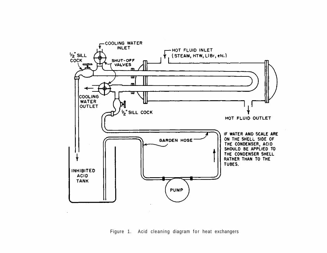
Figure 1 . Ac id c lean ing diagram f o r heat exchangers

b o t t o m o u t l e t t o t h e pump. The t a n k o u t l e t s h o u l d be a male g a r d e n hose c o n n e c t i o n so t h a t t h e t a n k and pump may be c o n n e c t e d by a ga rden h o s e .
S p e c i f i c a t i o n s f o r t he p u r c h a s e o f t h e pump f o r t h i s p u r p o s e a r e a s f o l l o w s :
1 - P o s i t i v e p r e s s u r e pump, 3 / 4 " p o r t s i z e , c a p a c i t y 5 . 7 gpm a t 10' h e a d , maximum 2 1 . 6 p s i g , b r o n z e pump body m a t e r i a l , neoprene i m p e l l e r m a t e r i a l , s t a i n l e s s s t e e l s h a f t , 3 / 4 " e x t e r n a l ga rden hose c o n n e c t i o n s , 1/8 h p w i t h r e l a y s t a r t and t h e r m a l o v e r l o a d p r o t e c t o r , t o t a l l y e n c l o s e d , 1750 rpm, 115 v , 6 0 c y c l e a c , w i t h s e r v i c e k i t (as Co le -Pa rmer pump, c a t . n o . 7 0 3 6 - 1 , and 7036-6 s e r v i c e k i t , a v a i l a b l e f o r $ 6 9 . 4 0 f r o m C o l e - P a r m e r , 7 4 2 5 N o r t h Oak Pa rk A v e . , C h i c a g o , I l l i n o i s 60648)
The d i l u t e i n h i b i t e d a c i d i s p r e p a r e d i n t h e a c i d c l e a n i n g assemb l y , a s p r e v i o u s l y d e s c r i b e d i n 7 . 2 o r a s d e s c r i b e d be low i n 7 . 3 . 2 , and i s pumped i n t o the h e a t e x c h a n g e r t h r o u g h t h e hose c o n n e c t i o n , t h e n i s r e t u r n e d b y hose c o n n e c t i o n t o t h e a c i d t a n k . C i r c u l a t i o n i s c o n t i n u e d u n t i l t h e c l e a n i n g i s c o m p l e t e a s i n d i c a t e d b y s u b s i d e n c e o f f o a m i n g o r d e p l e t i o n o f t he a c i d . A d d i t i o n a l a c i d s h o u l d b e added i f r e q u i r e d , and r e c i r c u l a t i o n and c l e a n i n g s h o u l d b e c o n t i n u e d u n t i l s c a l e removal i s c o m p l e t e . U s u a l l y a n h o u r o f c i r c u l a t i o n i s a d e q u a t e . The a c i d s t r e n g t h may be checked as d e s c r i b e d i n 7 .3 .3 . On c o m p l e t i o n o f c l e a n i n g , a 1% soda ash s o l u t i o n ( a b o u t 1 l b / 1 0 0 g a l ) s h o u l d be c i r c u l a t e d b r i e f l y , a f t e r w h i c h t h o r o u g h c i r c u l a t i o n and f l u s h i n g w i t h w a t e r i s recommended.
I f i t i s d e s i r e d t o c l e a n s m a l l d i a m e t e r ( 3 / 8 - t o 5 / 8 - i n c h ) coppe r t u b i n g , a s i n a d i s h w a s h e r b o o s t e r h e a t e r , p l a s t i c t u b i n g and c o n n e c t i o n s f o r f o r c i n g t h e t u b i n g i n t o t h e s c a l e a rea may p r o v e most e f f i c i e n t . S p e c i f i c a t i o n s f o r t h i s e q u i p m e n t a r e a s f o l l o w s :
1 - FBI Male c o n n e c t o r , b r a s s , 1 /2 " p i p e , 1 /4" t u b e , P a r t 4 - 8 FB 12-B 12 f t P a r k e r - POL t u b i n g , p o l y e t h y l e n e , 1 /4 " 0D t u b i n g ( a v a i l a b l e f r o m P a r k e r - H a n n i f i n C o r p . , 501 Sou th W o l f Road, Des P l a i n e s , f o r a few d o l l a r s )
7 . 3 . 2 F i l l and soak m e t h o d . P r e p a r e i n h i b i t e d d i l u t e a c i d , a s p r e v i o u s l y d e s c r i b e d , i n a 5 5 - g a l s t e e l drum o r e q u i v a l e n t . P r e
p a r e 33 g a l o f d i l u t e a c i d by a d d i n g 26 g a l o f w a t e r , t h e n 10 oz I t e m 41 C o r r o s i o n I n h i b i t o r B and one 6 - 1 / 2 g a l c a r b o y o f I t e m 40A m u r i a t i c a c i d , and m ix t h e c o n t e n t s . The p a r t t o b e c l e a n e d i s immersed i n t h e d i l u t e d a c i d f o r s e v e r a l hou rs u n t i l t he s c a l e i s removed.
46

7.3.3 Test method f o r checking s t reng th of a c i d . As the ac id is consumed in d i s s o l v i n g s c a l e , i t may be des i rab le to check
the ac id s t reng th to determine i f i t is adequate. The procedure is as f o l l o w s :
Measure 10 ml of the ac id s o l u t i o n accura te ly in a graduated c y l i n d e r and place in a cassero le . Add 2-4 drops of phen-o l p h t h a l e i n i n d i c a t o r and t i t r a t e w i t h IN sodium hydroxide* to a f a i n t p ink c o l o r . This is the endpoin t . The ml of IN sodium hydroxide requ i red m u l t i p l i e d by 0.35 = % of hyd roch lo r i c ac id in the sample, or m u l t i p l i e d by 0.97 = % su l famic ac id in the sample.
Concentrated hyd roch lo r i c ac id d i l u t e d w i t h 3 par ts o f water w i l l t es t approximately 7.7% or w i l l requ i re about 22.0 ml of IN NaOH to n e u t r a l i z e the 10 ml ac id sample. A l s o , 20 lb of su l famic ac id d isso lved in about 10 gal of water should t es t approximately 20% or will requ i re about 20.6 ml of IN NaOH to n e u t r a l i z e the 10 ml ac id sample.
When the ac id s t reng th has decreased to 2-3% or below, it may be discarded since most of i t s scale d i s s o l v i n g proper ty w i l l have been l o s t .
*The State Water Survey will furnish IN Sodium Hydroxide solution on request .
47

8. SAMPLING AND METHODS OF WATER ANALYSIS
8.1 Sampling
Water t es t s are of no value unless the sample tes ted is rep resen ta t i ve of the water being analyzed. In sampling water from w e l l s , i t is essen t i a l tha t the we l l has been pumped long enough to insure tha t the sample being taken represents the ground water from which the w e l l is f e d . Usual ly a sample w i l l be rep resen ta t i ve i f the we l l is pumped f o r at least 15 minutes. In sampling from lakes or r e s e r v o i r s , choice of a l oca t i on f o r ob ta in i ng a rep resen ta t i ve sample may be more d i f f i c u l t ; in gene ra l , the sample should not be taken too c lose to the shore l i n e , too c lose to incoming f l o w s , or in s lugg ish areas. In sampling from a f a u c e t , the water should be a l lowed to f low long enough so tha t i t is o f f a i r l y constant tempera tu re as rep resen ta t i ve of temperature cond i t i ons in the l a rge r p i p i n g , and f low should be regulated so tha t minimum sp lash ing and ae ra t i on of the sample occurs dur ing sampl ing. Cool ing tower samples may be c o l l e c t e d from a tap in the c i r c u l a t i n g l i n e previous to chemical a d d i t i o n or may be c o l l e c t e d from the coo l i ng tower basin away from the make-up water a d d i t i o n . E x p l i c i t d i r e c t i o n s are given f o r sampling b o i l e r water and condensate in 8 .1.1 and 8 . 1 . 2 .
Glass or p l a s t i c b o t t l e s may be employed fo r sampling raw, d i s t r i b u t i o n , coo l ing tower , b o i l e r , feedwater , o r condensate samples. P l a s t i c b o t t l e s should be employed i f accurate s i l i c a r e s u l t s are r equ i r ed . Bo i l e r wa te r , feedwater, and condensate should be sampled in glass b o t t l e s i f analyses f o r o i l content are requ i red . Samples should be stoppered as soon as c o l l e c t e d .
8 .1 .1 Sampling b o i l e r water . The f o l l o w i n g procedures should be app l ied in c o l l e c t i n g b o i l e r water samples:
(1) F i r s t , open the coo l i ng water valve to prov ide adequate f low f o r c o o l i n g .
(2) Blow sample l i nes f ree of stagnant water and sediment by opening the b o i l e r water sampling valve f o r a 15-30 second p e r i o d . A cont inuous f low of approximately 1 p i n t per minute, cooled to less than 120 F, should be maintained before c o l l e c t i n g sample.
(3) Rinse the sample con ta iner at least th ree times by f i l l ing to 1/4 i t s capac i ty w i t h b o i l e r wa te r , shak ing , and then emptying.
(4) Take the sample when the b o i l e r is ope ra t i ng under normal
48

load c o n d i t i o n s , when the b o i l e r water is at normal opera t ing water l e v e l , and before manual blowdown f o r con t ro l o f so l i ds concen t ra t i on . A f t e r the t e s t s , the amount of manual blowdown or adjustment of the continuous blowdown can be determined from the t e s t r e s u l t s .
(5) Co l l ec t the b o i l e r water sample through a pipe extending to the bottom of the con ta ine r . Al low the conta iner to over f low at leas t f i v e volumes, and then c lose i t w i t h a stopper p rev ious ly r insed w i t h the sample water . ( I f the sample is to be tes ted w i t h i n 20 minutes, i t is not necessary to stopper the con ta i ne r . )
(6) A f t e r the sample is taken, shut the b o i l e r water va lve o f f ; then shut the coo l ing water va lve o f f .
8.1.2 Sampling condensate. The f o l l o w i n g are procedures f o r c o l l e c t i o n of condensate samples:
(1) Sample the condensate from the t o t a l f low of condensate re tu rn ing to the power p l a n t . The tes t of p u r i t y then ind ica tes whether raw or softened water contaminat ion is occu r r i ng anywhere in the system.
(2) Before t e s t i n g , cool the sample to room temperature by passage through a sample coo le r .
(3) Use the con ta ine r , p re fe rab l y g l a s s , only for condensate and label i t acco rd ing ly . Containers tha t have been used fo r raw and b o i l e r water samples o f ten c o n t r i b u t e d isso lved so l i ds contaminat ion from seams, e t c . , even a f t e r being scrupulous ly c leaned.
(4) Rinse the sample conta iner at least three times w i t h condensate before c o l l e c t i n g the sample to be t e s t e d .
(5) Test the sample immediately to avoid contaminat ion from a i r or dus t . Samples should not be f i l t e r e d .
8.1.3 Preparing and sh ipp ing of water samples. I f the water t e s t is to be made at the State Water Survey, these i n s t r u c t i o n s should
be f o l l o w e d :
(1) A f t e r sampling in a clean conta iner as recommended above, stopper the b o t t l e t i g h t l y . The screw cap on p l a s t i c conta iners should be tightened very securely.
49

(2) Label the sample b o t t l e , i nc lud ing the f o l l o w i n g i n f o r m a t i o n :
Name of I n s t i t u t i o n Kind of water and l oca t i on
( i nc lude b o i l e r and coo l ing tower numbers) Date
(3) I f b o t t l e is loose in the sample c o n t a i n e r , pack paper o r cardboard around i t .
(4) Address the package t o :
I l l i n o i s State Water Survey 605 East S p r i n g f i e l d Avenue Champaign, I l l i n o i s 61820
(5) Send the package by parce l post or Uni ted Pa rce l . I t should not be shipped Specia l D e l i v e r y , unless requested.
8.2 Water Tes t ing and Methods of Water Analyses
The only purpose of water t e s t i n g is to prov ide proper con t ro l of recommended t rea tments . I t is not f o r the purpose of record-keeping or of complet ing forms. When tes ts i nd i ca te undesired r e s u l t s , a d j u s t ments in t rea tmen t , blowdown, e t c . , as recommended in the con t ro l c h a r t s , should be immediately a p p l i e d . A minimum number of t es t s are p r e s c r i b e d , and these resu l t s are essen t i a l in ma in ta in ing i n s t i t u t i o n a l f a c i l i t i e s in the desi red proper opera t ing and maintenance-f ree c o n d i t i o n .
Annual and replacement requirements of t e s t i n g equipment and r e agents s h a l l be ordered from the State Standard S p e c i f i c a t i o n s f o r Water Test ing Reagents and Equipment. Reagents, w i t h except ion of Items 113-115 Ortho T o l i d i n e , w i l l ma in ta in the s p e c i f i e d concent ra t ion f o r a t leas t one year . A f resh supply of Ortho T o l i d i n e should be obta ined at l eas t every s i x months. Occas iona l ly standard s o l u t i o n s from a part i c u l a r b o t t l e or supply are o f f - s t a n d a r d . When t e s t r e s u l t s change r a d i c a l l y w i t h use of a new b o t t l e of reagent, i t is poss ib le t ha t the new supply may be o f f - s t a n d a r d . A sample of the o f f - s t a n d a r d s o l u t i o n may be sent to the State Water Survey f o r check ing , or the c o n d i t i o n may be reported to the Sta te Water Survey dur ing p l a n t v i s i t s .
Test ing equipment should be kept scrupu lous ly c l ean . Unless t h i s is done the t e s t w i l l be u n r e l i a b l e . Test ing equipment should be kept in good order . A l l b o t t l e s should be proper ly l abe led . S p i l l e d chemi ca l s should be cleaned immediately from tab le tops . Graduated c y l i n ders and casseroles should be r insed w i t h the water to be tes ted before conduct ing the a n a l y s i s . Care should be taken in measuring the t e s t volume of wa te r , in reading the automat ic b u r e t t e s , and in repo r t i ng the ppm r e s u l t s . The f o l l o w i n g t e s t methods are recommended f o r con t ro l o f water t reatment in the State I n s t i t u t i o n s .
50

8.2.1 Hardness t e s t (H)
Apparatus
B u r e t t e , 10 ml Automatic ( f o r Standard Hardness T i t r a t i n g So lu t i on ) ( I tem 5155)
Graduated Cy l inder ( I tem 5150)
1 oz B o t t l e , w i t h c a l i b r a t e d 0.5 ml dropper ( i tem 5154)
Porce la in Casserole ( I tem 5152)
S t i r r i n g Rod ( I tem 5153)
Brass Measuring Cup, 0.1 gm s i ze ( I tem 5197)
Reagents
Standard Hardness T i t r a t i n g So lu t i on (1 ml = 1 mg CaC03) ( I tem 5002, 5003)
Hardness Buf fer So lu t ion ( I tem 5011)
Hardness Ind i ca to r Powder ( I tem 5014)
Method
(1) Measure the amount of water to be tes ted in the graduated c y l i n d e r in accordance w i t h :
Recommended sample s ize Hardness ( t o keep t i t r a t i o n
(as CaC03) less than 10 ml) Factor
Up to 100 ppm 100 ml 10 100 to 400 ppm 50 ml 20 Above 400 ppm 20 ml 50
10 ml 100 5 ml 200
(2) Pour i n to the cassero le .
(3) Add 1 ml Hardness Bu f fe r and 1 brass measuring cup (0.14 gm) of Hardness I nd i ca to r Powder. I f the water turns b l u e , no hardness is p resent , the hardness is reported as " z e r o , " and the t e s t is d i scon t i nued . I f the water turns r e d , hardness is present and the t e s t should be con t inued .
(4) Squeeze the Standard Hardness T i t r a t i n g So lu t ion from the p l a s t i c b o t t l e to j u s t above the zero mark on the b u r e t t e , then a l l ow excess s o l u t i o n to d ra in au toma t i ca l l y back to the b o t t l e .
(5) While s t i r r i n g the water cons tan t l y and v igo rous ly w i t h the glass r o d , add Standard Hardness T i t r a t i n g So lu t ion drop by drop from the b u r e t t e u n t i l the red changes to b l ue . This is the endpo in t . Read the bu re t t e to the nearest 0.1 m l .
51
Resul ts
When t e s t i n g a 100 ml sample:
Bure t te reading in ml x 10 = ppm hardness (as CaC03)
Example: 5.6 ml x 10 = 56 ppm hardness (as CaC03)
52

8.2 .2 Calcium (Ca) and magnesium (Mg) hardness t es t s
Apparatus
B u r e t t e , 10 ml Automatic ( f o r Standard Hardness T i t r a t i n g So lu t ion ) ( I tem 5155)
B u r e t t e , 10 ml Automatic ( f o r Standard Acid S o l u t i o n , N/50) ( I tem 5155)
Graduated Cyl inder ( I tem 5150)
Porce la in Casserole ( I tem 5152)
S t i r r i n g Rod ( I tem 5153)
B o t t l e , w i t h dropper ( f o r Methyl Orange I nd i ca to r ) ( I tem 5154)
1 oz B o t t l e , w i t h c a l i b r a t e d 0.5 ml dropper ( f o r Sodium Hydroxide) ( I tem 5154
Brass Measuring Cup, 0.1 gm s ize ( I tem 5197)
Reagents
Standard S u l f u r i c Acid (N/50) ( I tem 5021, 5022)
Methyl Orange I nd i ca to r ( I tem 5029)
Standard Hardness T i t r a t i n g So lu t ion (I ml = I mg CaC03) ( I tem 5002, 5003)
Sodium Hydroxide So lu t i on (1 .0 N) ( I tem 5095)
Calcium I n d i c a t o r , powder ( I tem 5099)
Method
(1) Measure the amount of water to be tes ted in the graduated c y l i n d e r in accordance w i t h :
Recommended sample s ize Calcium ( t o keep t i t r a t i o n
(as CaC03) less than 10 ml) Factor
Up t o 100 ppm 100 ml 10 100 to 400 ppm 50 ml 20 Above 400 ppm 20 ml 50
10 ml 100 5 ml 200
(2) Pour i n to the cassero le .
(3) Squeeze the Standard S u l f u r i c Acid and the Standard Hardness T i t r a t i n g So lu t i on from the p l a s t i c b o t t l e s t o j u s t above the zero marks on the b u r e t t e s , then a l l ow excess s o l u t i o n s to d ra in au toma t i ca l l y back to the b o t t l e s .
(4) Add 2-3 drops of Methyl Orange I nd i ca to r and t i t r a t e w i t h N/50 S u l f u r i c Acid u n t i l the co lo r changes from ye l low to orange or f a i n t p ink .
(5) Now apply 1 brass measuring cup (0.20 gm) of Calcium Ind i ca to r and 2 ml (1 N) Sodium Hydroxide.
53
(6 ) Then t i t r a t e i m m e d i a t e l y w i t h Hardness T i t r a t i n g S o l u t i o n . I f c a l c i u m i s p r e s e n t , t he sample w i l l b e sa lmon p i n k i n c o l o r , and a s t he e n d p o i n t i s a p p r o a c h e d , i t w i l l d e v e l o p a p u r p l e t i n g e . The e n d p o i n t i s o r c h i d p u r p l e . Once t he e n d p o i n t i s r e a c h e d , a d d i t i o n a l t i t r a t i n g s o l u t i o n will not produce any further color change. The endpoint s h o u l d a lways be checked by a d d i n g one a d d i t i o n a l d rop o f t i t r a t i n g s o l u t i o n and o b s e r v i n g w h e t h e r f u r t h e r c o l o r change o c c u r s . I f f u r t h e r c o l o r change o c c u r s , t he e n d -p o i n t has n o t been reached and t he t i t r a t i o n s h o u l d be c o n t i n u e d . Read t h e b u r e t t e t o t h e n e a r e s t 0 . 1 m l .
R e s u l t s
C a l c i u m hardness (as CaC03) :
When t e s t i n g a 100 ml sample
B u r e t t e r e a d i n g in ml x 10 = ppm c a l c i u m ha rdness (as CaC03)
Examp le : 3.6 ml x 10 = 36 ppm c a l c i u m hardness (as CaC03)
Magnesium hardness (as CaC0 3 ) :
T o t a l H ppm - c a l c i u m H ppm = ppm magnesium H (as CaC03)
54

8.2.3 Phenolphthale in a l k a l i n i t y t e s t (P)
Apparatus
B u r e t t e , 10 ml Automatic ( f o r Standard S u l f u r i c Acid) ( I tem 5155)
Graduated Cy l inder ( I tem 5150)
B o t t l e , w i t h dropper ( f o r Phenolphthale in I nd i ca to r ) ( I tem 5154)
Porce la in Casserole ( I tem 5152)
S t i r r i n g Rod ( I tem 5153)
Reagents
Standard S u l f u r i c Acid (N/50) (1 ml = 1 mg CaC03) ( I tem 5021, 5022)
Phenolphthale in I n d i c a t o r ( I tem 5033)
Method
(1) Measure the amount of water to be tes ted in the graduated c y l i n d e r i n accordance w i t h :
P A l k a l i n i t y Recommended (as CaC03) s i ze of sample Factor
Up t o 25 ppm 100 ml 10 25-100 ppm 50 ml 20 100-400 ppm 20 ml 50 Above 400 ppm 10 ml 100
(2) Pour i n t o the cassero le .
(3) Add 2 drops of Phenolphthale in I n d i c a t o r . If the water does not change to a red c o l o r , there is no phenolphtha le in a l k a l i n i t y present and the " P " reading is repor ted as " z e r o . " If the water does change to a red c o l o r , pheno lphtha le in a l k a l i n i t y is present and the t e s t should be con t inued .
(4) Squeeze the Standard S u l f u r i c Acid from the p l a s t i c b o t t l e to j u s t above the zero mark on the b u r e t t e , then a l l ow the excess ac id to d ra in au tomat i ca l l y to the b o t t l e .
(5) While s t i r r i n g the water cons tan t l y w i t h the g lass rod , add Standard S u l f u r i c Acid drop by drop from the b u r e t t e to the casserole u n t i l the red co lo r disappears and the water resumes the co lo r i t showed before the Phenolphthale in I n d i c a t o r was added. This is the endpo in t . Read the b u r e t t e to the nearest 0.1 m l .
(6) Do not d iscard the sample, but save f o r other t es t s if M a l k a l i n i t y o r c h l o r i d e tes ts are requ i red .
Results
When t e s t i n g a 100 ml sample:
Bure t te reading in ml x 10 = ppm P a l k a l i n i t y (as CaC03)
Example: 7.0 ml x 10 = 70 ppm P a l k a l i n i t y (as CaC03)
55

8 .2 .4 To ta l (methyl orange) a l k a l i n i t y t e s t (M)
Apparatus
B u r e t t e , 10 ml Automatic ( f o r Standard S u l f u r i c Ac id) ( I tem 5155)
Graduated Cy l inder ( I tem 5150)
B o t t l e , w i t h dropper ( f o r Methyl Orange I n d i c a t o r ) ( I tem 5154
Porce la in Casserole ( I tem 5152)
S t i r r i n g Rod ( I tem 5153)
Reagents
Standard S u l f u r i c Ac id (N/50) (l ml = l mg CaC03) ( I tem 5021, 5022)
Methyl Orange I n d i c a t o r ( I tem 5029)
Method
(1) Add 2-4 drops of Methyl Orange I n d i c a t o r to the water in the cassero le remaining from the pheno lph tha le in a l k a l i n i t y t e s t . I f the water changes to an orange or red c o l o r , f r ee mineral ac i d is p resen t , there is no a l k a l i n i t y , and the "M" reading is repor ted as " z e r o . " The a c i d i t y may be determined by t i t r a t i o n w i t h standard a l k a l i ( I tem 5111), as d i r e c t e d in 8 .2 .16 . I f the water changes to a ye l low or straw c o l o r , methyl orange a l k a l i n i t y is present and the t e s t should be con t inued .
(2) Do not squeeze the Standard S u l f u r i c Ac id from the p l a s t i c b o t t l e back to the zero mark on the b u r e t t e , but leave i t at the reading shown at the endpoint of the P a l k a l i n i t y t e s t .
(3) Whi le s t i r r i n g the water cons tan t l y w i t h the g lass r o d , add Standard S u l f u r i c Ac id drop by drop from the b u r e t t e to the cassero le u n t i l the ye l l ow or s t raw c o l o r changes to a f a i n t orange or l i g h t p ink . Read the total burette reading to the nearest 0.1 ml, i nc l ud ing tha t used in the P a l k a l i n i t y de te rm ina t i on .
(4) Do not d i scard the sample, i f c h l o r i d e t e s t is r e q u i r e d .
Results
When t e s t i n g a 100 ml sample:
To ta l b u r e t t e reading in ml x 10 = ppm M a l k a l i n i t y (as CaC03)
Example: 7.0 ml x 10 = 70 ppm P a l k a l i n i t y (as CaC03)
10.0 ml x 10 = 100 ppm M a l k a l i n i t y (as CaC03)
Note A: The endpoint may be d i f f i c u l t to see in a r t i f i c i a l l i g h t . The most accurate r e s u l t s are secured i f the t e s t i s conducted in d a y l i g h t . Inexperienced operators gene ra l l y add too much a c i d , thereby secur ing an i n c o r r e c t endpoint of a d e f i n i t e red c o l o r . An a l t e r n a t i v e is to use the Mixed I n d i c a t o r Method, descr ibed in 8 .2 .14.
Note B: I f the sample tes ted is b o i l e r water w i th a comparat ive ly h igh concen t ra t i on of phosphate, the M reading w i l l have a tendency to fade .
56

8.2 .5 Chlor ide tes t (CI)
Apparatus
B u r e t t e , 10 ml Automatic ( f o r Standard S i l v e r N i t r a t e ) ( I tem 5155)
Graduated Cyl inder ( I tem 5150)
B o t t l e , w i t h dropper ( f o r Potassium Chromate Ind i ca to r ) ( I tem 5154
Porce la in Casserole ( I tem 5152)
S t i r r i n g Rod ( I tem 5153)
Reagents
Standard S i l v e r N i t r a t e (1 ml = 1 mg CI) ( I tem 5042)
Potassium Chromate I n d i c a t o r ( I tem 5048)
Hydrogen Peroxide So lu t i on (3%) ( I tem 5043)
Method
(1) Measure the amount of water to be tes ted in the graduated c y l i n d e r in accordance w i t h :
Ch lor ide Recommended (as CI) s i z e of sample Factor
Up to 25 ppm 100 ml 10 25 to 100 ppm 50 ml 20 100 to 400 ppm 20 ml 50 Above 400 ppm 10 ml 100
(2) Add 4-8 drops of Potassium Chromate I n d i c a t o r to the water in the casserole remaining from the P a l k a l i n i t y t e s t . The water w i l l tu rn a ye l low c o l o r .
(3) Squeeze the S i l v e r N i t r a t e from the p l a s t i c b o t t l e to j u s t above the zero mark on the b u r e t t e , then a l low the excess s i l v e r n i t r a t e t o d ra in au toma t i ca l l y t o the b o t t l e .
(4) For waters that t e s t above 100 ppm s u l f i t e , add 2 ml Hydrogen Peroxide So lu t i on (3%) to the sample and s t i r we l l before t i t r a t i n g w i t h S i l v e r N i t r a t e .
(5) While s t i r r i n g the water cons tan t l y w i t h the glass rod , add S i l v e r N i t r a t e drop by drop from the b u r e t t e to the cassero le u n t i l a f a i n t red or dark orange c o l o r appears throughout the e n t i r e sample. This is the endpo in t . Read the bu re t t e to the nearest 0.1 m l .
Results
When t e s t i n g a 100 ml sample:
Bure t te reading in ml x 10 = ppm c h l o r i d e (as Cl)
Example: 5.1 ml x 10 = 51 ppm ch lo r i de (as Cl)
57

Note A: The endpoint is the first appearance of a permanent f a i n t red or dark orange co lo r and NOT the deep red co lo r tha t develops if S i l v e r N i t r a t e is added past the endpo in t .
Note B: Never make the c h l o r i d e t e s t d i r e c t l y on a sample. The P a l k a l i n i t y t e s t must be conducted f i r s t before determin ing the c h l o r i d e .
58

8.2.6 pH (or hydrogen ion concent ra t ion) t es t
A pH measurement by the glass e lec t rode meter is the most accurate method of determin ing pH; however, this equipment is expensive and is d i f f i c u l t to ma in ta i n . Therefore less accurate methods, which are be t t e r adapted to f i e l d usage, are recommended.
For pH values of 8.5 and below, method A, the c o l o r i m e t r i c pH method, is recommended. For pH values above 8 .5 , de terminat ion of the P and M a l k a l i n i t i e s and reference to Figure 2 shown in method B is recommended.
Method A - C o l o r i m e t r i c pH method
Apparatus
Tay lor pH S l i de Comparator, complete w i t h pH S l ides ( I tem 5160 Chlorphenol Red, Item 5161 Bromthymol B lue , Itern 5162 Phenol Red, Item 5166 Thymol Red, Item 5167 Meta Cresol Purple)
I nd i ca to r S o l u t i o n s , as f o l l o w s :
Name pH range Color change
Chlorphenol Red, Item 5116 5 .2 -6 .8 Yellow-Red Bromthymol B lue , Item 5107 6 .0 -7 .6 Yel low-Blue Phenol Red, I tern 5106 6 .8 -8 .4 Yellow-Red Thymol Red, I tern 5108 8.0-11.2 Yellow-Red Meta Cresol Purp le , I tern 5105 7 .6-9 .2 Yel low-Purp le
3 Test Tubes, 5 ml ( I tem 5180)
Tay lor D a l i t e Lamp, 110 v, 60 cyc le ( I tem 5182)
Preparat ion of sample
The sample should be taken at room temperature, through a coo l ing c o i l if necessary, and in such a manner as to prevent contaminat ion and contact w i t h the a i r . The t e s t should be made immediately a f t e r tak ing the sample, and the sample should not be f i l t e r e d . The cont a i ne r in which the sample is taken and a l l three 5 ml t es t tubes used in the t es t should be r insed repeatedly w i t h the sample before making the de te rm ina t i on .
Method
(1) F i l l three 5 ml t es t tubes exac t l y to the mark w i t h the sample.
(2) Place in the three center holes in the base of the comparator.
(3) By means of the p i p e t t e in the i n d i c a t o r b o t t l e , add 0.5 ml of the appropr ia te i n d i c a t o r to the middle tube o n l y , and Stopper the tube.
(4) Remove the middle tube from the base, mix the sample and the i n d i c a t o r by i n v e r t i n g the tube , and replace the tube in the middle ho l e .
59

(5) P l a c e t h e compa ra to r base o n t h e s h e l f o f t he D a l i t e lamp. Turn swi t c h ON.
(6) P l a c e the p H c o l o r s l i d e c o r r e s p o n d i n g t o t h e i n d i c a t o r used on the compara to r base .
(7) Move the p H c o l o r s t a n d a r d s l i d e t o t he r i g h t o r l e f t u n t i l t h e i n t e n s i t y o f t h e c o l o r o f t he sample i s matched by one o f t h e c o l o r s t a n d a r d s o f the s l i d e .
R e s u l t s
The pH v a l u e is t he number a p p e a r i n g on t h e s l i d e , as i n d i c a t e d by t h e ar row on the base .
Note A : I f t h e sample does n o t match one o f t he c o l o r s t a n d a r d s o f t he s l i d e , (1) t he sample may n o t be in t h e pH range of the s l i d e and the t e s t s h o u l d be r e p e a t e d u s i n g a d i f f e r e n t i n d i c a t o r and t h e c o r r e s p o n d ing pH c o l o r s t a n d a r d s l i d e , or (2) t h e sample may have become c o n t a m i n a t e d i n h a n d l i n g , o r (3) t he i n d i c a t o r s o l u t i o n may have d e t e r i o r a t e d o r become c o n t a m i n a t e d b y a c i d o r a l k a l i f umes , d u s t , e t c . I n case o f c o n t a m i n a t i o n , r e p e a t t h e t e s t w i t h a f r e s h sample and i f necessa ry employ f r e s h i n d i c a t o r s o l u t i o n .
Note B: I f t h e pH i n d i c a t e d is a t t h e ex t reme low end of t h e pH range of an i n d i c a t o r , as f o r e x a m p l e , pH 6 . 8 when u s i n g Phenol Red, r epea t t he t e s t u s i n g t h e lower range i n d i c a t o r , a s Bromthymol B l u e . I f t h e pH i n d i c a t e d is a t the h i g h end of t h e i n d i c a t o r r a n g e , as pH 7.6 w i t h t h e Bromthymol B l u e , r epea t t h e t e s t u s i n g the h i g h e r range i n d i c a t o r , Phenol Red.
Method B - pH by P and M a l k a l i n i t y
Method
(1) De te rm ine P and M a l k a l i n i t y by methods 8 . 2 . 3 , 8 . 2 . 4 o r 8 . 2 . 1 4 .
(2) Now r e f e r t o t h e c h a r t i n F i g u r e 2 , n o t i n g t h e P a l k a l i n i t y r e a d i n g on t h e h o r i z o n t a l s c a l e , t hen moving upward on t h e v e r t i c a l s c a l e t o t h e M (me thy l o range) a l k a l i n i t y .
(3) No te the p o s i t i o n o f t he p o i n t o n the g r a p h ; n o t e p o s i t i o n compared to t h e s l a n t i n g l i n e s l a b e l e d pH and e s t i m a t e t h e pH.
Example 1 Example 2
P a l k a l i n i t y = 30 ppm P a l k a l i n i t y = 49 ppm M a l k a l i n i t y = 120 ppm M a l k a l i n i t y = 150 ppm E s t i m a t e d pH = 9.8 E s t i m a t e d pH = 10 .1
(4) O r , d e t e r m i n e M/P by d i v i d i n g t h e M a l k a l i n i t y by t h e P a l k a l i n i t y and r e f e r t o t h e f o l l o w i n g t a b l e :
M/P pH M/P PH_ M/P PH
60 8 . 5 7 9 . 5 3 .6 10 .0 18 9 . 0 5 . 8 9 . 6 2 . 9 10 .2 10 9 . 3 4 . 2 9 . 8 2 . 4 10.4
60

Figure 2. pH determination from P and M alkalinity

8.2 .7 S u l f i t e t e s t (S03)
Apparatus
Bu re t t e , 10 ml Automatic ( f o r Standard Potassium Iod ide - loda te ) ( I tem 5155)
Graduated Cy l inder ( I tem 5150)
Porce la in Casserole ( I tem 5152)
S t i r r i n g Rod ( I tem 5153)
1 P l a s t i c Dipper ( f o r 1.0 gm Dual Purpose Starch I n d i c a t o r ) ( I tem 5198)
1 oz B o t t l e , w i t h dropper ( f o r Phenolphthale in I nd i ca to r ) ( I tem 5154)
Reagents
Standard Potassium lod ide - Ioda te (1 ml = 0.5 mg S03) ( I tem 5068)
Phenolphthale in I nd i ca to r ( I tem 5033)
Dual Purpose S u l f i t e I n d i c a t o r ( I tem 5072)
Method
(1) Add 1 p l a s t i c d ipper (1.0 gm) of Dual Purpose Starch Ind ica t o r to cassero le .
(2) Measure the amount of water to be tes ted in the graduated c y l i n d e r in accordance w i t h :
S u l f i t e Recommended (S03) s ize of sample Factor
Up to 100 ppm 50 ml 10 100-500 ppm 10 ml 50
(3) Pour i n to the cassero le .
(4) Stir well.
(5) Add 3 drops of Phenolphtha le in I nd i ca to r to the cassero le .
(6) I f s o l u t i o n turns red , add more Dual Purpose I n d i c a t o r , u n t i l the s o l u t i o n re tu rns t o i t s o r i g i n a l c o l o r .
(7) Squeeze the Standard Iod ide - loda te So lu t i on from the p l a s t i c b o t t l e to j u s t above the zero mark on the b u r e t t e , then a l low excess s o l u t i o n to d r a i n au toma t i ca l l y back to the b o t t l e .
(8) While s t i r r i n g the sample cons tan t l y w i t h the s t i r r i n g rod , add Potassium Iod ide - loda te drop by drop from the bu re t te to the cassero le u n t i l a f a i n t but permanent blue co lo r appears. This is the endpoin t . Be ca re fu l not to over-t i t r a t e the endpo in t . Read bu re t t e to nearest 0.1 ml (as 1.2 or 1.8) .
62

Results When testing a 50 ml sample:
Burette reading in ml x 10 = ppm sulfite (as SO3) Example: 2.8 ml x 10 = 28 ppm sulfite (as S03)
Note A: To insure the most accurate results, the sample should be collected without contact with the air, cooled below 120 F, and tested promptly.
Note B: The accuracy of this test is affected by any oxidizable substance in the water sample, such as organic matter or sulfides, which may cause the sulfite reading to be higher than the amount actually present.
63

8.2 .8 Phosphate t es t (PO4)
Apparatus
Taylor High Phosphate Comparator, complete, range 5 to 100 ppm ( I tem 5159)
High Phosphate Mix ing Tube graduated at 5, 15, and 17-1/2 m l , w i t h rubber stopper ( I tem 5183)
2 Test Tubes, 5 ml ( I tem 5180)
Dispensing B o t t l e , p i n t s i ze ( f o r Molybdate Reagent) ( I tem 5158)
Funnel ( I tem 5156)
F i l t e r Paper, Whatman #5, 12-1/2 cm diameter ( I tem 5109)
Tay lor D a l i t e Lamp, 110 v, 60 cyc le ( I tem 5182)
Brass Measuring Cup, 0.1 gm s ize ( I tem 5197)
Test Tube Cleaning Brush ( I tem 5201)
Reagents
Phosphate I nd i ca to r Powder ( I tem 5075)
Molybdate Reagent So lu t i on * ( I tem 5084 [*Contains strong acids and should be handled with caution.]
D i s t i 1 led Water
Preparat ion of water sample to be tes ted
I t is imperat ive tha t the water sample to be tes ted is f r ee from suspended matter or s ludge. Mere t races w i l l cause ser ious e r r o r s . F i l t e r the water through the same f i l t e r paper as many times as requ i red to produce a c l ea r sample. A new f i l t e r paper should be used f o r each t e s t conducted.
Method
(1) F i l l the phosphate mix ing tube to the 5 ml (bottom) mark w i t h the f i l t e r e d water sample.
(2) F i l l to the 15 ml (middle) mark w i t h Molybdate Reagent.
(3) Add two level measuring cups f u l l of the Phosphate I n d i ca tor Powder to the phosphate mix ing tube.
(4) Inser t the rubber stopper and mix. If a blue co lo r does not develop in 5 minutes, there are no phosphates p resen t , the PO4 reading is reported as " z e r o , " and the tes t is d i scont i n u e d . I f phosphates are p resen t , a blue co lo r w i l l develop and the tes t should be con t inued .
(5) Place the phosphate mix ing tube in the middle hole of the comparator.
(6) F i l l two 5 ml t e s t tubes w i t h the f i l t e r e d b o i l e r water and place these t e s t tubes in the holes on e i t h e r s ide of the phosphate mix ing tube.
64
(7) P l ace c o m p a r a t o r o n s h e l f o f t h e D a l i t e Lamp. T u r n s w i t c h ON.
(8) Move t h e c o l o r s t a n d a r d s l i d e t o t h e r i g h t o r l e f t u n t i l t h e i n t e n s i t y o f t h e c o l o r o f t h e sample i s matched b y one o f t h e c o l o r s t a n d a r d s o f t h e s l i d e .
R e s u l t s
The p h o s p h a t e i n ppm i s t h e number a p p e a r i n g on t h e s l i d e as i n d i c a t e d by the a r r o w on t h e b a s e . I f t h e p h o s p h a t e exceeds 100 ppm, d i s c a r d t h e t e s t . Repeat t h e t e s t , u s i n g 2 - 1 / 2 m l o f t h e f i l t e r e d w a t e r samp l e ( i n s t e a d o f 5 m l ) ; d i l u t e t o t h e b o t t o m mark ( 5 m l ) w i t h d i s t i l l e d w a t e r and r e p e a t t h e t e s t s t a r t i n g w i t h s t e p 2 . M u l t i p l y t h e r e a d i n g by 2 to o b t a i n P0 4 in ppm.
65

8.2 .9 Chromate t e s t (CrO4)
Apparatus
B u r e t t e , 10 ml Automatic ( f o r N/40 Sodium T h i o s u l f a t e ) ( I tem 5155)
Graduated Cy l inder ( I tem 5150)
Porce la in Casserole ( I tem 5152)
S t i r r i n g Rod ( I tem 5153)
Reagents
NAO Sodium T h i o s u l f a t e ( I tem 5119)
T r i Purpose Chromate I n d i c a t o r Powder, packets ( I tem 5121)
D i s t i l led water
Method
(1) Measure the amount of water to be tes ted in the graduated c y l i n d e r i n accordance w i t h :
Chromate Recommended (asCr0 )4 s ize of sample Factor
0-100 ppm 50 ml 20 Above 100 ppm 20 ml 50
D i l u t e the 20 ml sample to 50 ml w i t h d i s t i l l e d water in the g raduated c y l i n d e r before pour ing i n t o the cassero le .
(2) Open one packet of T r i Purpose Chromate I n d i c a t o r and pour i t s e n t i r e contents i n t o the casserole and s t i r w i t h the g lass rod u n t i l the i n d i c a t o r i s d i s s o l v e d .
(3) Squeeze the Sodium T h i o s u l f a t e So lu t ion from the p l a s t i c b o t t l e to j u s t above the zero mark on the b u r e t t e , then a l low excess s o l u t i o n to d ra in au toma t i ca l l y back to the b o t t l e .
(4) T i t r a t e w i t h N/40 Sodium T h i o s u l f a t e u n t i l the s o l u t i o n turns to a straw ye l l ow . At t h i s po in t the endpoint is near and the t i t r a t i o n should be conducted s l ow l y . The endpoint is when the ye l low c o l o r disappears and the s o l u t i o n turns to a c l e a r or a l i g h t b lue c o l o r . Read b u r e t t e to nearest 0.1 m l .
Results
When t e s t i n g a 50 ml sample:
Buret te reading in ml x 20 = ppm chromate (as Cr04
Example: 2.0 ml x 20 = 40 ppm chromate (as Cr04)
66
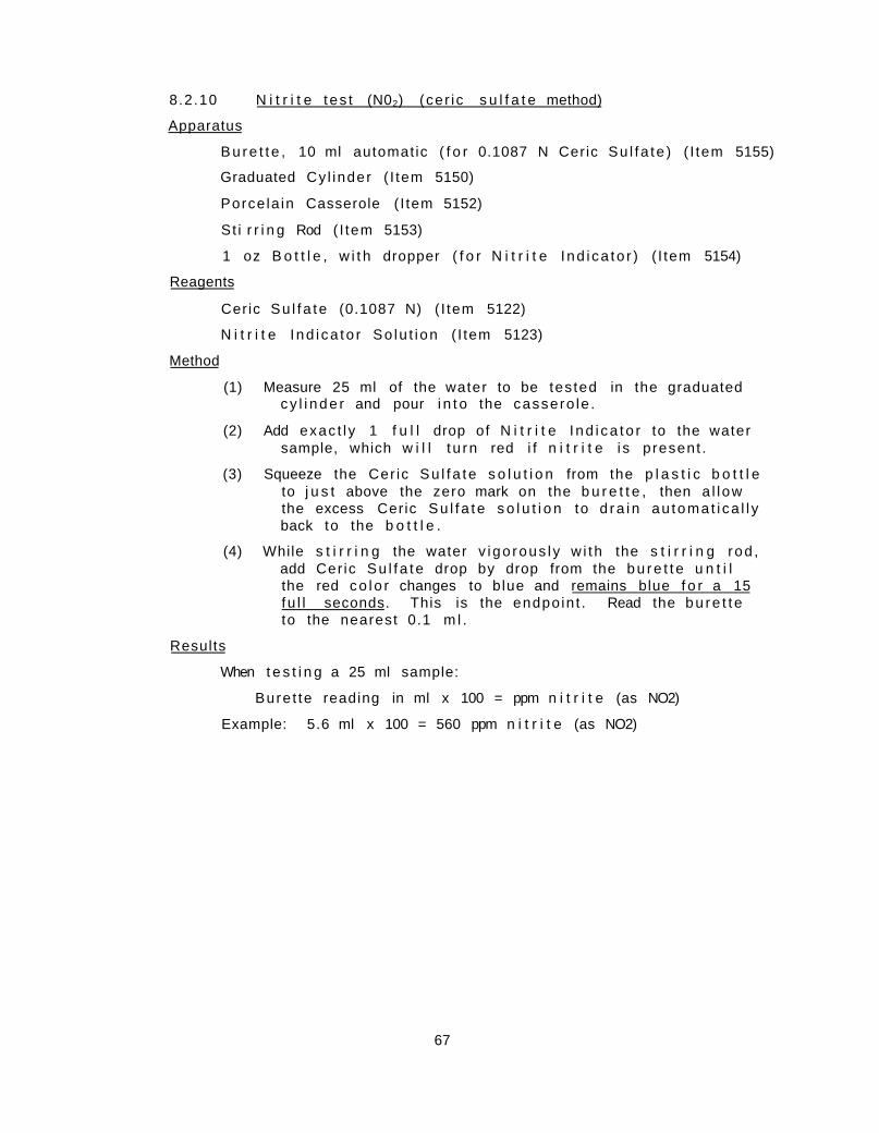
8.2.10 N i t r i t e t es t (N02) (cer ic s u l f a t e method)
Apparatus
B u r e t t e , 10 ml automat ic ( f o r 0.1087 N Ceric Su l fa te ) ( I tem 5155)
Graduated Cy l inder ( I tem 5150)
Porce la in Casserole ( I tem 5152)
St i r r i n g Rod ( I tem 5153)
1 oz B o t t l e , w i t h dropper ( f o r N i t r i t e I nd i ca to r ) ( I tem 5154)
Reagents
Ceric Su l f a te (0.1087 N) ( I tem 5122)
N i t r i t e I nd i ca to r So lu t ion ( I tem 5123)
Method
(1) Measure 25 ml of the water to be tes ted in the graduated c y l i n d e r and pour i n t o the cassero le .
(2) Add exac t l y 1 f u l l drop of N i t r i t e I nd i ca to r to the water sample, which w i l l t u rn red i f n i t r i t e i s present .
(3) Squeeze the Cer ic Su l f a te s o l u t i o n from the p l a s t i c b o t t l e to j u s t above the zero mark on the b u r e t t e , then a l l ow the excess Ceric Su l f a te s o l u t i o n to d r a i n au toma t i ca l l y back to the b o t t l e .
(4) While s t i r r i n g the water v igo rous l y w i th the s t i r r i n g rod , add Cer ic Su l f a te drop by drop from the b u r e t t e u n t i l the red c o l o r changes to blue and remains blue f o r a 15 fu l l seconds. This is the endpo in t . Read the b u r e t t e to the nearest 0.1 m l .
Results
When t e s t i n g a 25 ml sample:
Bure t te reading in ml x 100 = ppm n i t r i t e (as NO2)
Example: 5.6 ml x 100 = 560 ppm n i t r i t e (as NO2)
67

8.2.11 E l e c t r i c a l c o n d u c t i v i t y t e s t ( b o i l e r o r coo l i ng tower d i sso lved solids)
The e l e c t r i c a l c o n d u c t i v i t y method is a s imple and rap id way to determine the t o t a l d isso lved s o l i d s con ten t . I t is based on the p r i n c i p l e that i on i zab le so l i ds in water cause the s o l u t i o n to conduct e l e c t r i c i t y . The h igher the concen t ra t ion o f i on i zab le s a l t s , the g rea te r the conductance of the sample. Pure wa te r , f r ee from ion izab le s o l i d s , possesses a very low conductance. The E l e c t r i c a l Conduc t i v i t y Instrument used f o r t h i s de te rmina t ion measures the t o t a l i o n i c concent r a t i o n of the water sample, the value of which may be converted to ppm. Suspended s o l i d s or sludge content is not measured, s ince these so l i ds are not in s o l u t i o n .
Apparatus
E l e c t r i c a l Conduc t i v i t y Instrument (as Beckman Model RDR104F, RD1811 or o lder models) f o r 105-120 v o l t , 50-60 cyc le (1-500 and 20-10,000 or 500-20,000 micromhos range) ( I tem 5190)
AC e l e c t r i c a l o u t l e t
Po lys tyrene Dip C e l l , 2.0 c e l l constant ( I tem 5192)
0-220 F Dia l Thermometer ( I tem 5194)
100 ml Capacity Cy l i nde r , not graduated ( I tem 5193)
Brass Measuring Cup, 0.1 gm s ize ( f o r G a l l i c Acid) ( I tem 5197)
Reagents
Phenolphthale in I nd i ca to r So lu t i on ( I tem 5033)
G a l l i c Ac id ( I tem 5057)
Method
(1) Connect instrument to 110 v ac e l e c t r i c a l o u t l e t , connect d ip c e l l and tu rn instrument swi tch to the " o n " p o s i t i o n .
(2) Pour approximately 50 ml of sample i n to c y l i n d e r ( s u f f i c i e n t t o cover a i r vents i n d i p c e l l ) .
(3) Add 2-4 drops of Phenolphthale in I n d i c a t o r and s u f f i c i e n t G a l l i c Acid to change the s o l u t i o n from p ink to c o l o r l e s s . (Usual ly 2 brass measuring cup fu ls are s u f f i c i e n t . )
(4) Determine temperature of sample w i t h the thermometer, and set the po in te r on the instrument temperature d i a l acco rd ing l y .
(5) Now immerse the d ip c e l l in the sample and move the c e l l up and down several times under the leve l of the water sur face to remove a i r bubbles ins ide the c e l l s h i e l d . (Keep the d ip c e l l a t leas t 1/2 inch o f f the bottom of the c y l i n d e r when tak ing the f o l l o w i n g read ing . )
(6) Now ad jus t the upper instrument d i a l u n t i l the dark segment of the tube reaches i t s widest opening.
68

R e s u l t s
Report the results in micromhos, as read from the d i a l . The r e s u l t s i n ppm may b e c a l c u l a t e d b y m u l t i p l y i n g t h e d i a l r e a d i n g b y 0 . 9 .
69

8.2.12 E l e c t r i c a l c o n d u c t i v i t y t e s t (condensate d isso lved s o l i d s )
The presence of mineral s o l i d s in condensate, caused by contamina t ion of condensate by raw, softened water or o the r contaminants, may be determined by an e l e c t r i c a l c o n d u c t i v i t y instrument having a range of measurement of 1-500 micromhos.
The de tec t ion of mineral s o l i d s in condensate is very impor tant s ince the presence of raw or sof tened water in the condensate system w i l l cause ove r - l oad ing o f the feedwater system, which w i l l r e s u l t i n increased scale and co r ros ion and decreased e f f i c i e n c y of the e n t i r e power p l a n t .
Apparatus
E l e c t r i c a l Conduc t i v i t y Instrument (as Beckman Model RDR104F, RD181I or o lde r models) (1-500 micromhos and 20-10,000 or 500-20,000 micromhos), 105-120 v o l t , 50-60 c y c l e , complete ( I tem 5190)
AC e l e c t r i c a l o u t l e t
Po lys ty rene Dip C e l l , 0.1 c e l l constant ( I tem 5191)
Dia l thermometer ( I tem 5194
100 ml Capacity C y l i n d e r , not graduated ( I tem 5193)
Reagents
None
Method
(1) A l low condensate to f low f o r severa l minutes before sampling (see 8 . 1 . 2 ) . Rinse conta iner several t imes w i th the sample before c o l l e c t i n g f o r a n a l y s i s . Co l l ec t sample in a clean glass con ta iner (used s p e c i f i c a l l y f o r condensate) and p re fe rab l y cool by passage through small heat exchanger.
(2) Connect instrument to 110 v ac e l e c t r i c a l o u t l e t , connect d ip c e l l , and t u r n instrument swi tch t o the " o n " p o s i t i o n .
(3) Pour approximately 50 ml of sample i n to c y l i n d e r , r i nse e l e c t rode and thermometer, take temperature reading and set temperature d i a l a c c o r d i n g l y .
(4) Cel l should res t 1/2 inch or more o f f the bottom of c y l i n d e r when a d j u s t i n g the upper instrument d i a l to i t s w idest opening in the dark segment of the tube . Repeat r i n s i n g u n t i l cons is ten t reading i s ob ta ined .
Results
Report the results in micromhos, as read from the d i a l . The r e s u l t s in ppm may be c a l c u l a t e d by m u l t i p l y i n g the d i a l reading by 0 .6 .
Note A: Values above 20 micromhos are usua l l y an i n d i c a t i o n tha t raw or sof tened water contaminat ion is o c c u r r i n g .
70

8.2.13 Test to check c o n d u c t i v i t y instrument and e lec t rode
The e l e c t r i c a l c o n d u c t i v i t y instrument should be checked weekly f o r accuracy by t e s t i n g the c o n d u c t i v i t y of a known s o l u t i o n ( I tem 5021, 5022, N/50 S u l f u r i c A c i d ) ,
Since a l l models of c o n d u c t i v i t y t es te r s have not been s tandard ized by the manufacturer at the same temperature, the c o n d u c t i v i t y of N/50 ac id may be d i f f e r e n t . O r i g i n a l l y c o n d u c t i v i t y t es te r s were s tandard ized at 18 C (64 F) and l a t e r at 25 C (77 F ) . Dependent on the model number of c o n d u c t i v i t y t es te r s manufactured by Beckman Inst ruments , the cond u c t i v i t y of N/50 ac id ( I tem 5021, 5022) should be as f o l l o w s :
Conduc t i v i t y of N/50 ac id Model number (micromhos)
E l e c t r i c a l Conduc t i v i t y Instruments (Solu-Br idge 1-99; or 200-299; or a l l Betz Conducto Bridges) ( I tem 5190) 4300-5300
E l e c t r i c a l Conduc t i v i t y Instrument (Solu-Br idge 100-199, or 300-399; dual range model RD1251, RDR104F or RD181l) ( I tem 5190) 5000-6200
I n s t r u c t i o n s f o r conduct ing the t e s t are as f o l l o w s :
(1) Connect instrument to 110 v ac e l e c t r i c a l o u t l e t , t u rn on instrument s w i t c h , then connect d ip c e l l and place in ungraduated p l a s t i c c y l i n d e r ( I tem 5193).
(2) Pour s u f f i c i e n t N/50 S u l f u r i c Acid ( I tem 5021, 5022) i n to c y l i n d e r to cover a i r vents o f d ip c e l l , usua l ly about 50 m l .
(3) A f t e r immersing d ip c e l l in the sample, move c e l l up and down several times under the leve l of the water to remove a i r bubbles ins ide the c e l l s h i e l d .
(4) Determine the temperature of the sample w i t h the d i a l t he r mometer ( I tem 5194) and set the temperature d i a l on the instrument acco rd ing l y .
(5) When ad jus t i ng upper instrument d i a l to i t s widest opening of the dark segment of the " e l e c t r i c eye" tube , keep the d ip c e l l a t leas t 1/2 inch o f f the bottom of the c y l i n d e r .
Results
Report the r e s u l t in micromhos shown on the large d i a l . The r e s u l t s should be repor ted weekly in the upper l e f t hand corner of the b o i l e r water con t ro l r e p o r t .
In case the r e s u l t s are not w i t h i n the s p e c i f i e d ranges shown above, the e l ec t r ode should be soaked in successive l o t s of N/50 S u l f u r i c A c i d , or i f a more rap id c lean ing procedure is p r e f e r r e d , i t may be immersed for I minute only in (1:1) S u l f u r i c Acid ( I tem 5062) or in (1:1) Hydroc h l o r i c A c i d . A f t e r the c leaning procedure, the e lec t rode should be
71

r insed w i th wa te r , then re tes ted w i t h a f resh l o t o f N/50 S u l f u r i c Ac id . I f the proper t e s t i s then not ob ta ined , i t i s l i k e l y tha t the e lec t rode requi res r e p l a t i n i z a t i o n , r e p a i r , o r replacement. The e lec t rode may be sent to the Sta te Water Survey f o r r e p l a t i n i z i n g .
A spare e lec t rode ( I tem 5192) should be kept on hand at a l l t imes . However i f not a v a i l a b l e , the State Water Survey w i l l be g lad to loan an e lec t rode or an ins t rument , or b o t h , upon request .
72

8.2.14 Mixed i n d i c a t o r ( t o t a l ) a l k a l i n i t y t e s t
Apparatus
B u r e t t e , 10 ml automatic ( f o r Standard S u l f u r i c Acid) ( I tem 5155)
Graduated Cy l inder ( I tem 5150)
B o t t l e , w i t h dropper ( f o r Mixed Ind i ca to r ) ( I tem 5112)
Porce la in Casserole ( I tem 5152)
S t i r r i n g Rod ( I tem 5153)
Reagents
Standard S u l f u r i c A c i d , N/50, (l ml = 1 mg CaC03) ( I tem 5021, 5022)
Mixed I n d i c a t o r (Bromcresol Green - Methyl Red) ( I tem 5112)
Method
(1) Add 2-4 drops of Mixed I nd i ca to r to the water in the cassero le remaining from the phenolphtha le in a l k a l i n i t y t e s t . I f the water changes to a l i g h t p ink or red c o l o r , f ree mineral ac id is p resent . There is the re fo re no a l k a l i n i t y present and the "M" reading is repor ted as " z e r o . " I f the water changes to a green or b lue green c o l o r , "M" a l k a l i n i t y is present and the t e s t is con t inued .
(2) Do not squeeze the standard s u l f u r i c ac i d from the p l a s t i c b o t t l e back to the zero mark on the b u r e t t e , but leave i t at the reading shown at the endpoint of the "P" a l k a l i n i t y t e s t .
(3) While s t i r r i n g the water cons tan t l y w i t h the glass rod , add standard s u l f u r i c ac id drop by drop from the bu re t t e to the cassero le u n t i l the green or b lue green c o l o r changes to a l igh t p i nk .
Results
When t e s t i n g a 50 ml sample:
Bure t te reading in ml times 20 = ppm "M" a l k a l i n i t y (as CaC03)
Example: 16.5 ml x 20 = 330 ppm "M" a l k a l i n i t y (as CaC03)
When t e s t i n g a 10 ml sample:
Bure t te reading in ml times 100 = ppm "M" a l k a l i n i t y (as CaC03)
Example: 3.1 ml x 100 = 310 ppm "M" a l k a l i n i t y (as CaC03)
73

8.2.15 Ac i d i ty
This t e s t i s genera l l y requ i red on ly f o r t e s t i n g water t r ea ted w i t h ac id or f o r t e s t i n g the e f f l u e n t from a d e a l k a l i z i n g type ion exchanger, which is regenerated w i t h a c i d . Water samples c o l l e c t e d a t these loca t ions w i l l usua l l y t e s t ac id (p ink) to methyl orange and must be t i t r a t e d w i t h a standard a l k a l i s o l u t i o n in order to ob ta in an eva lua t ion o f a c i d i t y .
Apparatus
B u r e t t e , 10 ml automat ic ( f o r Standard Sodium Hydroxide) ( I tem 5111)
Graduated Cy l inder ( I tem 5150)
Porce la in Casserole ( I tem 5152)
Two b o t t l e s w i t h droppers ( f o r Phenolphthale in I n d i c a t o r ( I tem 5154 and Methyl Orange I n d i c a t o r ( I tem 5154 or Mixed I n d i c a t o r ( I tem 5112))
S t i r r i n g Rod ( I tem 5153)
Reagents
Standard Sodium Hydroxide (N/50) ( I tem 5111)
Phenolphthale in I nd i ca to r ( I tem 5033)
Methyl Orange I nd i ca to r ( I tem 5029) or Mixed I n d i c a t o r ( I tem 5112)
Method
(1) Measure a 50 ml sample and pour i n t o cassero le .
(2) Add 2-4 drops of Methyl Orange I nd i ca to r or Mixed I n d i c a t o r . I f the water does not change to a p ink or red c o l o r , there is no methyl orange a c i d i t y and the "M" reading is repor ted as " z e r o . " I f the water does change to a p ink or red c o l o r , Methyl Orange a c i d i t y is present and the t e s t should be con t inued .
(3) Squeeze the Sodium Hydroxide from the p l a s t i c b o t t l e to j u s t above the zero mark on the b u r e t t e , then a l l ow the excess ac id to d ra in au toma t i ca l l y t o the b o t t l e .
(4) While s t i r r i n g the water w i t h the glass rod , add Standard Sodium Hydroxide drop by drop from the b u r e t t e to the cassero le u n t i l the p ink c o l o r changes to f a i n t orange when using Methyl Orange or u n t i l the p ink co lo r changes to green or blue green when using Mixed I n d i c a t o r . This is the endpo in t . Read the bu re t t e to the nearest 0.1 ml and record a f t e r m u l t i p l y i n g by 20 as the "M" a c i d i t y .
(5) Do not d i sca rd the sample and do not squeeze the Standard Sodium Hydroxide from the p l a s t i c b o t t l e back to the zero mark on the b u r e t t e , but leave i t at the reading shown at the endpoint of the Methyl Orange ("M") A c i d i t y t e s t .
74

(6) Add 2 drops of Phenolphthalein Indicator. (7) If the sample turns pink, report the "P" acidity the same
as the "M" acidity. (8) If the sample does not turn pink, add a separate 50 ml
sample to a clean casserole and add 2 drops of Phenolphthalein Indicator. Then, while stirring the water slowly with the glass rod, add Standard Sodium Hydroxide drop by drop from the burette to the casserole until a faint pink color appears (lasting at least 10 seconds). This is the endpoint. Read the burette to the nearest 0.1 ml and record after multiplying x 20 as the Phenolphthalein ("P") acidity.
Results When testing a 50 ml sample and using Methyl Orange or Mixed
Indicator Burette reading in ml times 20 = ppm "M" acidity
When using Phenolphthalein Indicator Total burette reading in mls times 20 = ppm "P" acidity
75

8.2 .16 A l k a l i n i t y in condensate
The purpose of t h i s t e s t is to determine the approximate amine con ten t , so tha t the proper con t ro l of amine t reatment may be main ta ined.
A f t e r c o l l e c t i n g the condensate sample as d i r e c t e d in 8 . 1 . 2 , the P and M a l k a l i n i t y t e s t is conducted.
Apparatus
B u r e t t e , 10 ml automat ic ( f o r Standard S u l f u r i c Acid) ( I tem 5155)
Graduated Cy l i nde r , 100 ml ( I tem 5151)
Porce la in Casserole ( I tem 5152)
Two b o t t l e s w i t h droppers ( f o r Phenolphtha le in I n d i c a t o r ( I tem 5154) and Methyl Orange I nd i ca to r ( I tem 5154 or Mixed I nd i ca to r ( I tem 5112))
S t i r r i n g Rod ( I tem 5153)
Reagents
Standard S u l f u r i c Ac id (N/50) (l ml = 1 mg CaC03) ( I tem 5021, 5022)
Phenolphthale in I nd i ca to r ( I tem 5033)
Methyl Orange I n d i c a t o r ( I tem 5029) or Mixed I nd i ca to r ( I tem 5112)
Method
(1) Mark a 100 ml graduated c y l i n d e r and cassero le to be used f o r condensate a n a l y t i c a l purposes o n l y .
(2) A f t e r r i n s i n g c y l i n d e r and cassero le w i t h the condensate sample several t imes , measure 100 ml sample and add to cassero le .
(3) Add 2-4 drops of Phenolphthale in I n d i c a t o r . If the sample remains c o l o r l e s s , record " P " a l k a l i n i t y as ze ro .
(4) I f sample is p i n k , add N/50 S u l f u r i c Ac id u n t i l sample is c o l o r l e s s . This is the endpo in t . Read b u r e t t e to nearest 0.1 m l .
(5) Do not squeeze the Standard S u l f u r i c Acid from the p l a s t i c b o t t l e back to the zero mark on the b u r e t t e , but leave i t at the reading shown at the endpoint of the P a l k a l i n i t y t e s t .
(6) Now add 2-6 drops of Methyl Orange I nd i ca to r or Mixed I nd i ca to r and cont inue t i t r a t i o n w i t h N/50 S u l f u r i c Acid to a p ink endpo in t . Read the bu re t t e to the nearest 0.1 m l .
Results
Bure t te reading to pheno lphtha le in endpoint x 10 = ppm P a l k a l i n i t y (as CaC03)
76

Total burette reading to methyl orange or mixed indicator x 10 = ppm M alkalinity (as CaC03)
Example: 0.8 ml required to phenolphthalein endpoint x 10 = 8 ppm P alkalinity
Example: 1.6 ml required to methyl orange endpoint x 10 = 16 ppm M alkalinity
Interpretation Usually it is recommended that the P alkalinity be maintained at a slight positive value, but below 6 ppm and that the M alkalinity be maintained below 30 ppm.
77

9. REFERENCE MATERIAL
The f o l l o w i n g books may be r e f e r r e d to f o r f u r t h e r i n f o r m a t i o n on wa te r t e s t i n g methods and water t r e a t m e n t :
Annual Book of ASTM Standards, Part 23, Water; Atmospheric Analyses, 1971, American Soc ie t y f o r T e s t i n g and M a t e r i a l s
Betz Handbook of Industrial Water Conditioning, 1962, Betz Labora t o r i e s , I n c . , T revose , Pa. 19047
Boiler-Watev-Treatment Manual for Federal-Plant Operators, Handbook 5, Goldman, 1951, U. S. Government P r i n t i n g O f f i c e , Washi n g t o n , D. C. 20401
Cooling Water, It's Chemistry and Fundamentals, 1971 Wr igh t Chemical C o r p . , Chicago, I l l i n o i s 60622
High Temperature Water Systems, L i e b e r g , 2nd E d . , 1963, The I n d u s t r i a l P r e s s , New York 13, N. Y.
Introduction to Chemistry of Industrial Boiler Water, 1965, Wr igh t Chemical C o r p . , Ch icago, I l l i n o i s 60622
Industrial Water Treatment Practice, Hamer, Jackson, and Thurston, 1971, B u t t e r w o r t h I n c . , Wash ing ton , D. C.
Manual on Industrial Water, STP442, 1969, American Soc ie t y f o r T e s t i n g and M a t e r i a l s
Questions and Answers on Boiler-Feedwater Conditioning, Berk, 1962, U. S. Dept . of I n t e r i o r , Bureau of M ines , U. S. Government P r i n t i n g O f f i c e , Wash ington, D. C. 20401
Standard Boiler Operators' Questions and Answers , Elonka, I969, M c G r a w - H i l l , I n c . , New Y o r k , N. Y.
Standard Methods for the Examination of Water, Sewage and Industrial Wastes, T h i r t e e n t h E d i t i o n , 1971 , American P u b l i c Hea l th A s s o c i a t i o n
Water Treatment for Industrial and Other Uses, Nordell, Second E d i t i o n , 1961 , Re inho ld P u b l i s h i n g Corp.
Water is Everybodys ' Business, Behrman, I968, Doubleday Book C o . , I n c .
Water Quality and Treatment, 3rd Edition, 1971, McGraw-Hill, I n c . , New Y o r k , N. Y.
78

APPENDIX A. PREPARATION OF WATER TEST REPORTS
The purpose of water t e s t i n g and the repo r t i ng of tes ts is to a t t a i n proper water treatment by accurate and e f f i c i e n t c o n t r o l , and as a r e s u l t , to e l i m i n a t e ser ious opera t ing outages and high maintenance cos ts . As the appropr ia te tes ts are made, the resu l t s are recorded on one of the f i v e repor t forms discussed below. Reference to these water t reatment records then shows c l e a r l y any changes in t e s t s , chemical dosages, and o p e r a t i o n , so the s i g n i f i c a n c e of such changes can be s tud ied to determine the need f o r a c t i o n .
The f i v e water t reatment repor ts are e n t i t l e d Bo i l e r Water Contro l Repor t , Cool ing Water Treatment Repor t , Hot Water Treatment Report , Cold Process Softener Contro l Report , and Lime Soda Softener Control Report . The use of these forms w i l l vary s l i g h t l y from p lan t to p lan t because of d i f f e rences in the equipment, and may vary from time to t ime because of changing problems. The completed repor t forms are sent each week to the State Water Survey.
The water t reatment repor ts should be prepared neat ly and in complete form. The name of the i n s t i t u t i o n and the date should be included at the top of each r e p o r t . Upon complet ion of t e s t i n g , each operator should s ign h is i n i t i a l s on the repor t oppos i te h is t e s t i n g r e s u l t s . When the repor t is completed, i t should be signed by the Chief Engineer and by the Superintendent or Warden of the i n s t i t u t i o n or by the D i rec to r of the Physical Plant before ma i l i ng each week to the f o l l o w i n g address:
I l l i n o i s State Water Survey A t t : R. W. Lane Box 232, Urbana, I l l i n o i s 61801
A l . B o i l e r Water Control Report ( F i g . A l )
Complete and accurate b o i l e r water t e s t r esu l t s should be repor ted d a i l y . In the la rger p lan ts tha t operate more compl icated water t r e a t i n g equipment, tes ts each s h i f t are recommended. In p lan ts employing d i r e c t ac id t rea tment , t es t s of the make-up or feedwater a l k a l i n i t y are recommended every 4 hours.
The e l e c t r i c a l c o n d u c t i v i t y t es t (8 .2 .13) on N/50 s u l f u r i c ac id should be conducted weekly to determine whether the e l e c t r i c a l cond u c t i v i t y instrument is performing c o r r e c t l y . The resu l t s are recorded in the space a f t e r Electrode Test, near the upper l e f t hand corner under Boiler Tests.
79

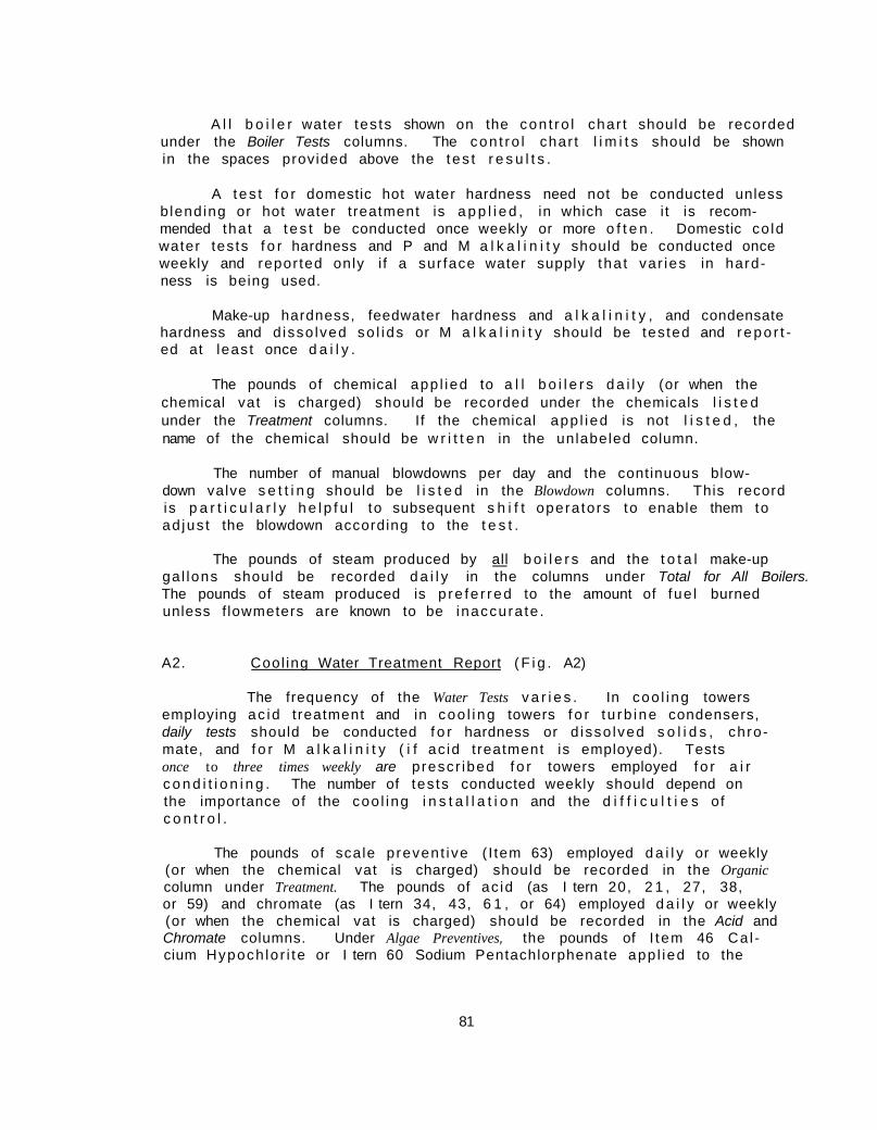
A l l b o i l e r water tes ts shown on the con t ro l char t should be recorded under the Boiler Tests columns. The con t ro l char t l i m i t s should be shown in the spaces provided above the tes t r e s u l t s .
A t es t f o r domestic hot water hardness need not be conducted unless b lending or hot water t reatment is a p p l i e d , in which case i t is recommended tha t a t e s t be conducted once weekly or more o f t e n . Domestic co ld water tes ts f o r hardness and P and M a l k a l i n i t y should be conducted once weekly and repor ted only i f a sur face water supply tha t var ies in hardness is being used.
Make-up hardness, feedwater hardness and a l k a l i n i t y , and condensate hardness and d isso lved so l i ds or M a l k a l i n i t y should be tes ted and repo r t ed at least once d a i l y .
The pounds of chemical app l ied to a l l b o i l e r s d a i l y (or when the chemical vat is charged) should be recorded under the chemicals l i s t e d under the Treatment columns. If the chemical app l ied is not l i s t e d , the name of the chemical should be w r i t t e n in the unlabeled column.
The number of manual blowdowns per day and the continuous blow-down valve s e t t i n g should be l i s t e d in the Blowdown columns. This record is p a r t i c u l a r l y h e l p f u l to subsequent s h i f t opera tors to enable them to ad jus t the blowdown according to the t e s t .
The pounds of steam produced by all b o i l e r s and the t o t a l make-up ga l lons should be recorded d a i l y in the columns under Total for All Boilers. The pounds of steam produced is p re fe r red to the amount of fue l burned unless f lowmeters are known to be inaccura te .
A2. Cool ing Water Treatment Report ( F i g . A2)
The frequency of the Water Tests v a r i e s . In coo l ing towers employing ac id t reatment and in coo l i ng towers f o r t u rb ine condensers, daily tests should be conducted f o r hardness or d isso lved s o l i d s , chro-mate, and f o r M a l k a l i n i t y ( i f ac id t reatment is employed). Tests once to three times weekly are p rescr ibed f o r towers employed f o r a i r c o n d i t i o n i n g . The number of tes ts conducted weekly should depend on the importance of the coo l ing i n s t a l l a t i o n and the d i f f i c u l t i e s of c o n t r o l .
The pounds of scale prevent ive ( I tem 63) employed d a i l y or weekly (or when the chemical vat is charged) should be recorded in the Organic column under Treatment. The pounds of ac id (as I tern 20, 2 1 , 27, 38, or 59) and chromate (as I tern 34, 43, 6 1 , or 64) employed d a i l y or weekly (or when the chemical vat is charged) should be recorded in the Acid and Chromate columns. Under Algae Preventives, the pounds of I tem 46 Ca l cium Hypoch lo r i te or I tern 60 Sodium Pentachlorphenate app l ied to the
81

Figure A2
Figure A3

coo l i ng tower d a i l y or weekly should be recorded. The continuous blow-down valve s e t t i n g or t imer s e t t i n g ( i f blowdown is i n d i v i d u a l l y t imer c o n t r o l l e d ) should be recorded under Blowdown. The metered ga l lons of make-up water used d a i l y or weekly (or between chemical vat charges) should be recorded in the Make-up column.
A3. Hot Water Treatment Report ( F i g . A3)
I n s t i t u t i o n s app ly ing caus t i c soda, sodium s i l i c a t e , o r carbon d iox ide to the domestic hot water system to con t ro l co r ros ion and scale should prepare and mail t h i s repor t weekly. The b lending va lve s e t t i n g should be recorded in the upper l e f t hand corner of the r e p o r t , and the water temperatures should be entered on the center l i n e near the bottom of the r e p o r t .
Tests f o r hardness (not ca l c i um) , P and M a l k a l i n i t y , and pH are requ i red once d a i l y . T e s t s Before Treatment are requi red on ly a t the f o l l o w i n g i n s t i t u t i o n s : Pont iac P e n i t e n t i a r y , Galesburg State Research H o s p i t a l , A. L. Bowen Ch i l d ren ' s Center , and Kankakee State H o s p i t a l . At the State Reformatory f o r Women at Dwight, these columns are used f o r record ing the ana lys is of the d i s t r i b u t i o n water near the po in t of chemical a p p l i c a t i o n and the After Treatment columns are used to record the ana lys is of the d i s t r i b u t i o n system near the ex t rem i t y of the system.
Under Treatment, the water meter read ings, the ga l lons of water t r e a t e d , and the pounds of chemical ( i n lb /10,000 ga l ) should be re corded by a l l the above i n s t i t u t i o n s each t ime the chemical vat is charged. At i n s t i t u t i o n s where only I tern 32 L iqu id Sodium S i l i c a t e is a p p l i e d , 4/5 p i n t of Itern 47 Sodium Hypoch lo r i te (or 1 ounce of I tern 46 Calcium Hypoch lor i te ) per 100 ga l l ons of the chemical vat should be app l i ed and recorded each t ime the vat is charged.
A4. Cold Process Softener Control Report ( F i g . A4)
Only i n s t i t u t i o n s tha t have co ld process so f tener equipment are requ i red to make t h i s weekly r epo r t . These i nc lude : Menard Pen i t e n t i a r y , I l l i n o i s State Farm, Vienna P e n i t e n t i a r y , Anna State H o s p i t a l , and T in l ey Park Mental Heal th Center.
Da i l y complete analyses i nc lud ing calc ium and magnesium of Raw Water (except T in ley Pa rk ) , Softener Effluent or Filter Influent, and Filter Effluent should be conducted and repor ted . In cases of changeable raw water ana lyses, it may be necessary to make a l l of these analyses more f r e q u e n t l y to prov ide proper c o n t r o l . At T i n l e y Park, on ly a weekly ana lys is of the raw we l l water is necessary, s ince t h i s ana lys is should be r e l a t i v e l y constant . The 2P-M va lue , ca l cu l a ted by m u l t i p l y i n g the
83


phenolphtha le in a l k a l i n i t y by 2 and s u b t r a c t i n g the M a l k a l i n i t y , is a measure of excess l ime t reatment , which must be c o n t r o l l e d to ob ta in proper so f t en ing as s p e c i f i e d in the so f tener con t ro l c h a r t . The M-H va lue , obta ined by s u b t r a c t i n g hardness from the M a l k a l i n i t y , is a measure of the soda ash treatment which must a lso be c o n t r o l l e d to obt a i n proper so f t en ing as s p e c i f i e d in the so f tener con t ro l c h a r t . Under Chemical Dosage, e i t h e r chemical dosages or the feeder s e t t i n g s should be recorded in the labeled chemical columns.
The Slurry Level is the leve l of sludge below the water sur face in the sof tened water o u t l e t area of the co ld process so f tener and should be determined by measurement and recorded. The Draft Tube sludge is sampled from the d r a f t tube (center po r t i on ) of the cold process so f tener and is determined by c o l l e c t i n g a 100 ml sample in. a graduated c y l i n d e r and observing the percentage of s e t t l e d sludge a f t e r 5 minutes. Under the Concentrator columns, the number of concen t ra to rs being opera ted, the t imer s e t t i n g of the concen t ra to rs , and the sludge volume of concent ra tor sludge samples should be recorded d a i l y . The sludge volumes of the concent ra tor sludge samples are determined by the same method used fo r determin ing d r a f t tube s ludge.
The f o l l o w i n g a lso should be recorded d a i l y : 1) the per iod of time tha t the main sludge valve is opened; 2) the p r o p e l l e r RPM of so f t ene r ; 3) the temperature of the i n l e t water ; and 4) the t o t a l volume of t rea ted water .
A5. Lime Soda Softener Control Report (F i g . A5)
This repor t on hot process lime soda so f tener tes ts is re qu i red only from Pont iac P e n i t e n t i a r y , I l l i n o i s So ld ie rs & Sa i l o rs Ch i l d ren ' s School , and Peoria State H o s p i t a l , the only State i n s t i t u t i ons having t h i s equipment.
The Chemical Tests are requi red each s h i f t and are very s i m i l a r to those requ i red f o r the co ld process so f t ene r , except tha t ca lc ium and magnesium determinat ions are not r equ i red . The 2P-M r e s u l t s , which are a measure of the excess lime t rea tment , are obta ined by m u l t i p l y i n g the phenolphtha le in a l k a l i n i t y by 2 and s u b t r a c t i n g the M a l k a l i n i t y . The M-H r e s u l t s , which are a measure of the soda ash t rea tment , are obta ined by s u b t r a c t i n g the hardness from the M a l k a l i n i t y . Recommendations are given in the so f tener con t ro l char t as to the 2P-M and M-H resu l t s f o r proper s o f t e n i n g .
The Middle Sludge Volume is determined by sampling 100 ml of the sludge from the middle sampling valve in the bottom cone of the so f tener in a 100 ml graduated c y l i n d e r . The sludge volume in the c y l i n d e r a f t e r 5 minutes is recorded in the labeled column.
The Setting re fe rs to the t imer s e t t i n g of the p ropo r t i on i ng
85

Figure A5

equipment, which is actuated by the e l e c t r i c o n t a c t water meter. This s e t t i n g is ra ised or lowered to increase or decrease the amount of chemical to be a p p l i e d .
The Chemicals Per Inch re fe rs to the pounds of hydrated l ime , soda ash, and sodium aluminate d isso lved per inch in the so f tener chemical tank.
Inches Per Charge is the inches of chemical s o l u t i o n added to the chemical tank each time the chemical tank is charged. For example, if 4 lb l ime , 2 lb soda ash, and 1/4 lb sodium aluminate are app l ied per i n c h , and a 6- inch charge of chemicals is a p p l i e d , the opera to r should d i sso lve 6 x 4 = 2 4 lb l ime , 6 x 2 = 12 lb soda ash, and 6 x 1/4 = 1-1/2 lb sodium aluminate in 6 inches of water in the tank and mix we l l before s t a r t i n g p ropor t i ona te t reatment .
The water meter readings are taken and recorded each time the tank is charged to g ive the ga l lons t r e a t e d . Then the Gallons of Water Treated Per Inch is ca l cu la ted by d i v i d i n g the ga l lons t rea ted by the inches of chemical charged. Comparing t h i s value w i t h the opera t ing recommendations and w i t h past records provides a measure of the accuracy of the chemical p r o p o r t i o n i n g .
87

APPENDIX B. GRADING FEEDWATER TREATMENT EFFICIENCY
Each year the S t a t e Water Survey rev iews the wate r t r e a t i n g o p e r a t i o n s a t each o f t he S ta te p l a n t s , grades these o p e r a t i o n s , and makes recommendations to t he Award Committee t h a t awards be made to i n s t i t u t i o n s hav ing c e r t a i n grade l e v e l s . The Award Committee c o n s i s t s o f the f o l l o w i n g p e r s o n n e l : R . J . Coleman, Ch ie f S u p e r v i s i n g E n g i n e e r , Depar t ment of Mental H e a l t h ; P r o f . E. F. Hebrank, Mechanica l E n g i n e e r i n g Depar tment , U n i v e r s i t y o f I l l i n o i s ; W. B. Manker, Ch ie f Mechanica l E n g i n e e r , Department of General S e r v i c e s ; and R. W. Lane, Sen io r Chemis t , I l l i n o i s S t a t e Water Survey.
Present recommendations a re t h a t i n s t i t u t i o n s r e c e i v i n g a grade o f 85 and above r e c e i v e the Standard C e r t i f i c a t e , and t h a t i n s t i t u t i o n s r e c e i v i n g a grade of 92 and above r e c e i v e a S u p e r i o r C e r t i f i c a t e .
The f o l l o w i n g s i x c l a s s i f i c a t i o n s are i n c l u d e d i n c a l c u l a t i n g the f i n a l g r a d e :
(A) Adequacy of weekly wa te r t r ea tmen t r e p o r t s (B) Observance o f t r e a t m e n t c o n t r o l f rom month ly w a t e r
sample a n a l y s i s r e p o r t s (C) I n s p e c t i o n o f wa te r t e s t i n g f a c i l i t i e s (D) I n s p e c t i o n o f wa te r t r e a t i n g equipment (E) Adequacy o f wa te r t r e a t i n g chemica l s u p p l i e s (F) C o n s i d e r a t i o n f o r d i f f i c u l t wa te r t r e a t m e n t c o n t r o l
C l a s s i f i c a t i o n (A) on week ly wa te r t r e a t m e n t r e p o r t s (20 p o i n t t o t a l ) i s graded as f o l l o w s :
Submission o f r e p o r t s : A l l r e c e i v e d 0 1 not r e c e i v e d - I 2 not r e c e i v e d -2 3 not r e c e i v e d -3 4 not r e c e i v e d -4
Submission o f N/50 a c i d c o n d u c t i v i t y r e p o r t : 100% r e p o r t e d d u r i n g year 0
75% r e p o r t e d d u r i n g year -1 50% r e p o r t e d d u r i n g year -2 25% r e p o r t e d d u r i n g year -3
0% r e p o r t e d d u r i n g year -4
88
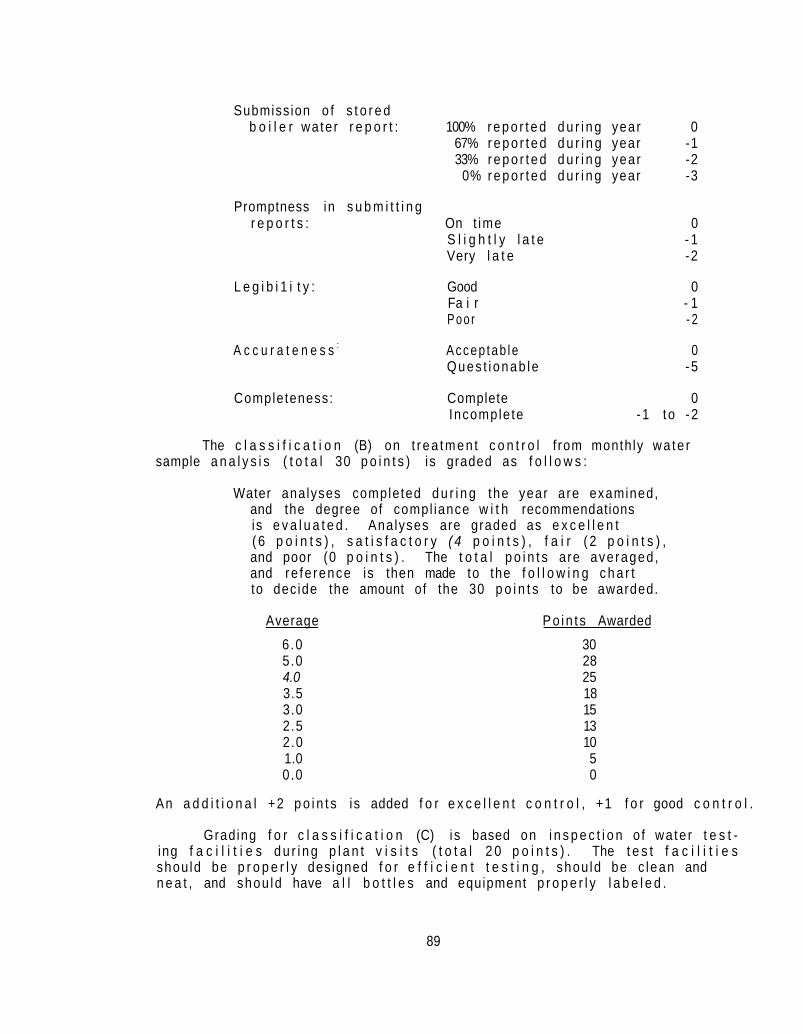
Submission o f s t o r e d b o i l e r wa te r r e p o r t : 100% r e p o r t e d d u r i n g year 0
67% r e p o r t e d d u r i n g year -1 33% r e p o r t e d d u r i n g year -2
0% r e p o r t e d d u r i n g year -3
Promptness in s u b m i t t i n g r e p o r t s : On t ime 0
S l i g h t l y l a t e - 1 Very l a t e -2
L e g i b i 1 i t y : Good 0 Fa i r - 1 P o o r - 2
A c c u r a t e n e s s : Accep tab le 0 Ques t i onab le -5
Completeness: Complete 0 Incomple te -1 t o -2
The c l a s s i f i c a t i o n (B) on t r ea tmen t c o n t r o l f rom month ly wa te r sample a n a l y s i s ( t o t a l 30 p o i n t s ) is graded as f o l l o w s :
Water analyses completed d u r i n g the year a re examined, and the degree of compl iance w i t h recommendations is e v a l u a t e d . Analyses are graded as e x c e l l e n t ( 6 p o i n t s ) , s a t i s f a c t o r y ( 4 p o i n t s ) , f a i r ( 2 p o i n t s ) , and poor (0 p o i n t s ) . The t o t a l p o i n t s are averaged , and re fe rence is then made to the f o l l o w i n g c h a r t to dec ide the amount of the 30 p o i n t s to be awarded.
Average Po in t s Awarded 6 .0 30 5.0 28 4.0 25 3.5 18 3.0 15 2.5 13 2.0 10 1.0 5 0.0 0
An a d d i t i o n a l +2 p o i n t s i s added f o r e x c e l l e n t c o n t r o l , +1 f o r good c o n t r o l .
Grading f o r c l a s s i f i c a t i o n (C) i s based on i n s p e c t i o n o f wa te r t e s t ing f a c i l i t i e s d u r i n g p l a n t v i s i t s ( t o t a l 2 0 p o i n t s ) . The t e s t f a c i l i t i e s shou ld be p r o p e r l y des igned f o r e f f i c i e n t t e s t i n g , shou ld be c lean and n e a t , and shou ld have a l l b o t t l e s and equipment p r o p e r l y l a b e l e d .
89

Compar i sons o f a l l t e s t i n g f a c i l i t i e s a r e made, and t o p g r a d e s are awarded t o t h e most s a t i s f a c t o r y f a c i l i t i e s .
C l a s s i f i c a t i o n (D) i s based o n i n s p e c t i o n o f w a t e r t r e a t i n g e q u i p ment d u r i n g p l a n t v i s i t s ( t o t a l 1 0 p o i n t s ) . The e q u i p m e n t s h o u l d b e p r o p e r , and s h o u l d b e k e p t c o n t i n u o u s l y i n good o p e r a t i n g c o n d i t i o n and i n a c l e a n l y c o n d i t i o n .
C l a s s i f i c a t i o n (E) o n w a t e r t r e a t i n g c h e m i c a l s ( t o t a l 1 0 p o i n t s ) i s based o n w h e t h e r c h e m i c a l s a r e k e p t i n a d e q u a t e q u a n t i t y and unde r p r o p e r s t o r a g e c o n d i t i o n s . I f s u p p l i e s become e x h a u s t e d and r e a s o n a b l e e f f o r t s a r e n o t made t o o b t a i n r e p l a c e m e n t , t h e g r a d e w i l l b e l o w e r e d .
I n c l a s s i f i c a t i o n (F) f o r d i f f i c u l t w a t e r t r e a t m e n t c o n t r o l , a g r a d e o f 1 0 i s awarded t o i n s t i t u t i o n s e m p l o y i n g a c i d t r e a t m e n t o r h o t l i m e - s o d a t r e a t m e n t , and t o i n s t i t u t i o n s e m p l o y i n g w a t e r s w h i c h a r e p a r t i c u l a r l y d i f f i c u l t t o t r e a t . L e s s e r p o i n t s a r e awarded t o i n s t i t u t i o n s e m p l o y i n g t h e s i m p l e r z e o l i t e - s o f t e n e d w a t e r t r e a t m e n t c o n t r o l .
90

APPENDIX C. INSTRUCTIONS ON FORMS AND PROCEDURES
The purpose of this section is to furnish instructions for clerical help entering the engineering division of the physical plant service for the first time. It establishes uniform procedures and instructions for the preparation and use of report forms prepared by the staff in the office of the Chief Engineer.
A list of all the necessary forms concerning the operation of the Engineering Section of the Plant Operations is set forth, together with procurement and distribution instructions. Procurement of forms is the responsibility of the Business Manager through a written request by the Engineering Section.
C. 1 List of Forms
These instructions pertain to the following report forms:
WM-1 Repair Requisitions WM-4 Repai r Order WM-5 Work Request WM-6 Job Order Summary PH-175 Power Plant Daily Report - Generating and Heating PH-175A Power Plant Daily Report, High Temperature Hot
Water System PH-175B Mechanical and Electrical Daily Log - Heating
Plant Only PH-175C Mechanical and Electrical Daily Log - Low
Pressure System PH-176 Chief Engineer's Monthly Operation Report PH-187 Annual Power Plant (Heat) PH-188 Annual Power Plant (Water & Electricity) SE-F Monthly Fluoridation Report (Required only for
activities having own source of supply) SE-30C Monthly Chlorination Report SE-31A Operations and Chemical Report on Water Puri
fication (Surface Water) SE-31B Bacteriological Report on Water Supply SE-31C Operational and Chemical Report on Water Puri
fication (Ground Water Supplies -- Lime or Zeolite Softened)
SE-SP2 Swimming Pool Report SWB-Form 4 Trickling Filter Plant Sewerage Treatment Plant
Report SWB-Form 4B Activated Sludge Plant Sewerage Treatment Plant
Report
91
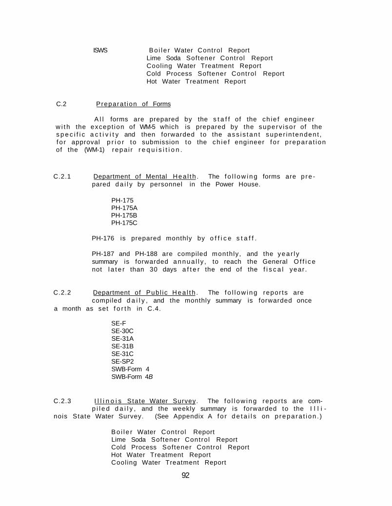
ISWS Bo i l e r Water Control Report Lime Soda Softener Control Report Cool ing Water Treatment Report Cold Process Softener Control Report Hot Water Treatment Report
C.2 Prepara t ion of Forms
A l l forms are prepared by the s t a f f of the ch ie f engineer w i t h the except ion of WM-5 which is prepared by the superv iso r of the s p e c i f i c a c t i v i t y and then forwarded to the a s s i s t a n t super in tenden t , f o r approval p r i o r to submission to the ch ie f engineer f o r p repara t ion of the (WM-1) repa i r r e q u i s i t i o n .
C.2.1 Department of Mental Hea l t h . The f o l l o w i n g forms are p re pared d a i l y by personnel in the Power House.
PH-175 PH-175A PH-175B PH-175C
PH-176 is prepared monthly by o f f i c e s t a f f .
PH-187 and PH-188 are compiled monthly, and the yea r l y summary is forwarded a n n u a l l y , to reach the General O f f i c e not l a t e r than 30 days a f t e r the end of the f i s c a l year .
C.2.2 Department of Pub l ic H e a l t h . The f o l l o w i n g repor ts are compiled d a i l y , and the monthly summary is forwarded once
a month as set f o r t h in C.4.
SE-F SE-30C SE-31A SE-31B SE-31C SE-SP2 SWB-Form 4 SWB-Form 4B
C.2.3 I l l i n o i s State Water Survey. The f o l l o w i n g repor ts are comp i l e d d a i l y , and the weekly summary is forwarded to the I l l i
nois State Water Survey. (See Appendix A f o r d e t a i l s on p repa ra t i on . )
B o i l e r Water Contro l Report Lime Soda Softener Contro l Report Cold Process Sof tener Control Report Hot Water Treatment Report Cool ing Water Treatment Report
92

C . 3 Procurement of Forms
C.3.1 From Printing Section. The following report forms are-ordered from the Printing Section, Department of General Services,
and shall be ordered on Printing Requisition (Form F-5P) with cost as noted.
WM-1 Repair Requisition (Cost: 18«j per pad) WM-4 Repair Order (Cost: 90¢ per pad) WM-5 Work Request (Cost: 46¢ per pad)
C.3.2 From Central Stores. The following report forms are ordered from the Department of Mental Health Central Stores on Form
DMH-508 at no charge.
PH-187 PH-188 WM-6 PH-175 PH-175A PH-175B PH-175C PH-176
C.3.3 From Publi c Health. The following report forms are ordered from the Department of Public Health, Division of Sanitary
Engineering, 535 West Jefferson, Springfield, Illinois 62706, at no charge.
SE-F SE-30C SE-31A SE-31B SE-31C SE-SP2 SWB-Form 4 SWB-Form 4B
C.3.4 From Water Survey. The following report forms are ordered from the Illinois State Water Survey, Box 232, Urbana, Illi
nois 61801, at no charge.
Boiler Water Control Report Lime Soda Softener Control Report Cold Process Softener Control Report Hot Water Treatment Report Cooling Water Treatment Report
93

C . 4 D i s t r i b u t i o n o f Forms
C o m p l e t e d f o r m s a r e d i s t r i b u t e d ( a t t h e t i m e i n t e r v a l s s p e c i f i e d i n C .2 ) t o t h e f o l l o w i n g l o c a t i o n s .
WM-1-4 O r i g i n a l - Shops ( n o c o p y ) WM-6 O r i g i n a l - C h i e f E n g i n e e r O f f i c e ( n o c o p y )
PH-176 O r i g i n a l - G e n e r a l O f f i c e Copy - O f f i c e o f t h e S u p e r v i s i n g A r c h i t e c t
703 S t a t e O f f i c e B u i l d i n g S p r i n g f i e l d
Copy - F i l e
PH-187 O r i g i n a l - G e n e r a l O f f i c e pH-188
Copy - O f f i c e o f t h e S u p e r v i s i n g A r c h i t e c t 703 S t a t e O f f i c e B u i l d i n g S p r i n g f i e l d
Copy - F i l e
SE-F O r i g i n a l - D i v i s i o n o f S a n i t a r y E n g i n e e r i n g SE-30C D e p a r t m e n t o f P u b l i c H e a l t h SE-31A 535 West J e f f e r s o n SE-31B S p r i n g f i e l d
S E - 3 1 C c o p y - G e n e r a l O f f i c e SE-SP2
Copy - F i l e SWB-Form4 O r i g i n a l - S a n i t a r y W a t e r B o a r d SWB-Form4 B D e p a r t m e n t o f P u b l i c H e a l t h
535 West J e f f e r s o n S p r i n g f i e l d
Copy - G e n e r a l O f f i c e Copy - F i l e
W a t e r S u r v e y O r i g i n a l - I l l i n o i s S t a t e W a t e r S u r v e y R e p o r t s A t t e n t i o n : R. W. Lane
Box 2 3 2 , U r b a n a , I l l i n o i s 61801 Copy - F i l e
94

APPENDIX D. PREPARING ANNUAL POWER PLANT REPORTS
D.l Report PH 187, Heat ( F i g . Dl)
The methods f o r c a l c u l a t i n g and prepar ing the Annual Power Plant Report PH 187 were publ ished November 1, 1972. These methods were reviewed and exp la ined at the Twen ty -F i f th Annual Short Course, October 23-27, 1972, and should be in accordance w i t h the f o l l o w i n g procedures. I terns are discussed and numbered here in the order of the columns in which they appear on the fo rm.
Boiler Pressure Psig. The b o i l e r pressure is read d i r e c t l y from a gauge on the b o i l e r in pounds per square inch (gauge) and is recorded on the mechanical d a i l y log (forms 175B,C) at the g iven hour. The average b o i l e r pressure f o r the month is recorded on the annual power p lan t repor t ( form PH 187).
The Annual Data recorded on the bottom l i n e is the average pressure f o r the 12 months.
Feedwater. The feedwater temperature is read to the nearest degree Fahrenheit from the thermometer in the feedwater heater d ischarge l i n e and is recorded hour ly on the mechanical d a i l y log (forms 175B,C). The average feedwater temperature f o r the month is recorded on the annual power p lan t repor t ( form 187).
The Annual Data recorded on the bottom l i n e is the average of the feedwater temperatures f o r the 12 months.
Steam Generated. The steam generated is read from each b o i l e r steam f low meter, i s t o t a l e d f o r a l l b o i l e r s , and is recorded on the mechanical e l e c t r i c a l d a i l y log (forms 175B,C). The t o t a l f o r the month is d i v i ded by 1,000,000. For example:
In t h i s case, 156.7 is the f i g u r e to be recorded under i tem 3 (PH 187) f o r the appropr ia te month.
The Annual Data recorded on the bottom l i n e is the summation of the 12 monthly readings of the steam generated per month.
Note: If the steam generated is not measured by a f low meter , t h i s i tem should not be f i l l e d i n .
95

State of Illinois - Department of Mental Health
ANNUAL POWER PLANT REPORT
Heat PH. 187 (Rev. 1 l / l / 7 2 )
Figure Dl
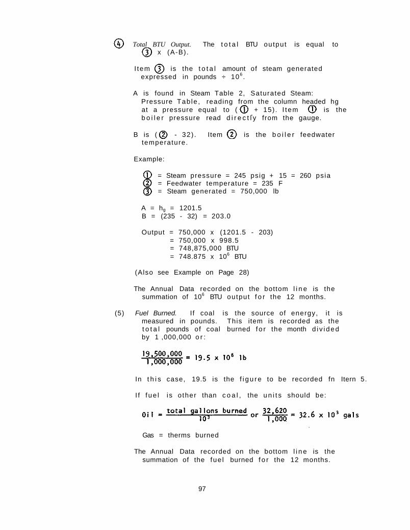
Total BTU Output. The t o t a l BTU output is equal to x (A-B) .
I tem is the t o t a l amount of steam generated expressed in pounds ÷ 106 .
A is found in Steam Table 2, Saturated Steam: Pressure Tab le , reading from the column headed hg at a pressure equal to ( + 15) . I t em is the b o i l e r pressure read d i r e c t l y from the gauge.
B is ( - 32) . Item is the b o i l e r feedwater temperature.
Example:
= Steam pressure = 245 psig + 15 = 260 ps ia = Feedwater temperature = 235 F = Steam generated = 750,000 lb
A = hg = 1201.5 B = (235 - 32) = 203.0
Output = 750,000 x (1201.5 - 203) = 750,000 x 998.5 = 748,875,000 BTU = 748.875 x 10⁶ BTU
(Also see Example on Page 28)
The Annual Data recorded on the bottom l i n e is the summation of 106 BTU output f o r the 12 months.
(5) Fuel Burned. I f coal is the source of energy, i t is measured in pounds. This item is recorded as the t o t a l pounds of coal burned f o r the month d i v i d e d by 1 ,000,000 o r :
In t h i s case, 19.5 is the f i g u r e to be recorded fn Itern 5.
I f f ue l i s o ther than c o a l , the u n i t s should be:
Gas = therms burned
The Annual Data recorded on the bottom l i n e is the summation of the fue l burned f o r the 12 months.
97

Heating Value of Fuel. The heat ing va lue of f ue l is the BTU content per u n i t .
When coal is used, i t is assumed t h a t the coal as f i r e d has 15% moisture in i t , but p lan ts having a mois ture gauge w i l l use the ac tua l percent mois ture tha t is determined from the coal sample. The BTU content as shown in the Mois ture Free column of the Coal Ana lys is repo r t is the f i g u r e to be used in c a l c u l a t i n g the average BTU content of the coal f i r e d ; an example of t h i s is shown in F i g . D2 on page 101.
The hea t i ng values f o r o i l o r gas are the f i g u r e s repor ted by the vendor.
The Annual Data on the bottom l i n e is the average BTU content f o r the 12 months.
Total BTU Input. When coal is used, t h i s value f o r each month is obta ined by m u l t i p l y i n g the t o t a l u n i t s o f f ue l burned ( I tem ) by the BTU content per u n i t ( I tem ) .
When o i l is used, t h i s value f o r each month is obta ined by m u l t i p l y i n g the t o t a l un i t s of f u e l burned ( I tem ) by the BTU content per u n i t ( I tem ) and d i v i d i n g by 1,000.
When gas is used, t h i s value f o r each month is ob ta ined by m u l t i p l y i n g the t o t a l u n i t s o f f u e l burned ( I tem ) by the BTU content per u n i t ( I tem ) and d i v i d i n g by 100,000.
The Annual Data on the bottom l i n e is the t o t a l u n i t s of fue l (Annual Data of I tern times the average BTU content per u n i t (Annual Data of I t e m ) as c a l c u l a t e d above.
(8) Actual Evanoration. The monthly ac tua l evaporat ion ( I tem ) of a b o i l e r is determined by d i v i d i n g the steam generated dur ing the month ( I tem ) by the t o t a l un i t s o f f ue l consumed dur ing the month ( I tem ) .
98

The Annual Data r e c o r d e d on the b o t t o m l i n e i s c a l c u l a t e d by d i v i d i n g the t o t a l s team g e n e r a t e d (Annual Data o f I t e m ) by t h e t o t a l f u e l burned (Annual Data o f I t e m ) as per above .
Unit Cost of Fuel. The f u e l c o s t per u n i t is t he average c o s t per u n i t o f t h e f u e l bu rned d u r i n g t h e mon th . As an examp le , the average c o s t o f c o a l ( f r o m t h e pu rchase o r d e r ) d u r i n g t h e month m i g h t b e $5 .55 per t o n ; f o r o i l , $0 .10 p e r g a l l o n ; o r f o r g a s , $0 .06 p e r t h e r m .
The Annual Data on t h e b o t t o m l i n e is t h e Annual Data o f I t e m d i v i d e d b y u n i t s o f f u e l bu rned f r om Annual Data o f I t e m . I f t h e f u e l i s c o a l , I t e m s h o u l d be m u l t i p l i e d by 10 and d i v i d e d by 2 ,000 b e f o r e making t h e d i v i s i o n . I f t h e f u e l i s o i l , m u l t i p l y b y 103 and i f t he f u e l i s g a s , d i v i s i o n can b e made d i r e c t l y .
Fuel Cost for the Month. When b u r n i n g c o a l , t h e f u e l c o s t f o r t h e month i s c a l c u l a t e d b y d i v i d i n g t h e t o t a l f u e l burned b y 2 ,000 and m u l t i p l y i n g t h e f u e l c o s t pe r t o n . For example :
T h i s f i g u r e i s c a r r i e d t o t h e n e a r e s t d o l l a r , s o the amount r eco rded wou ld be $ 5 4 , 1 1 3 .
The c o s t o f o i l f o r t h e month w i l l b e t h e t o t a l number o f g a l l o n s o f o i l m u l t i p l i e d b y t h e c o s t per g a l l o n .
The c o s t o f gas f o r t he month w i l l be t h e t o t a l amount as b i l l e d mon th l y by the gas company.
The Annual Data on t h e b o t t o m l i n e i s o b t a i n e d by t o t a l i n g t h e 12 mon th l y c o s t s .
Make-up Water. Make-up w a t e r as read f r om the w a t e r me te r i s u s u a l l y measured i n g a l l o n s , i s r e c o r d e d d a i l y o n t h e mechan ica l e l e c t r i c a l d a i l y l o g ( fo rms 175B.C) , i s t o t a l e d f o r t h e mon th , and i s c o n v e r t e d to 106 pounds by m u l t i p l y i n g g a l l o n s by 8 .33 and by d i v i d i n g by one m i l l i o n .
99

An example i s :
I f the water meter reads in cubic f e e t , the m u l t i p l i e r is 62 .4 , ra the r than 8 .33 , to convert cubic fee t to pounds.
The Annual Data on the bottom l i n e is the summation of the t o t a l of the m i l l i o n pounds of make-up water used dur ing the 12 months.
Percent Make-up. Percent make-up is c a l c u l a t e d from the pounds of make-up water d i v i ded by the steam generated m u l t i p l i e d by 100 o r :
As an example:
Percent make-up is recorded to one decimal p o i n t ; in t h i s case, the percent make-up f o r the month would be recorded as 47.2%.
The Annual Data on the bottom l i n e is c a l c u l a t e d by d i v i d i n a the t o t a l make-up water (Annual Data of I t e m ) by the t o t a l pounds of steam generated (Annual Data of I tem ) and m u l t i p l y i n g by 100.
Boiler Efficiency . The percent b o i l e r e f f i c i e n c y is ca l cu la ted as f o l l o w s :
The Annual Data on the bottom l i n e is determined by the above formula using the Annual Data f i gu res f o r I t e m and I t e m and is recorded to one decimal p lace .
See Example on Page 28.
100

The BTU content as shown in the "Mo is tu re Free" column is the f i g u r e to be used in c a l c u l a t i n g the "Heat ing Value of Fuel BTU's /Un i t " f o r Item 6 of PH 187. If a composite sample repor t is rece ived , the BTU's shown in the "Mois ture Free" column of tha t repo r t should be used.
Assuming tha t the coal as f i r e d would have a moisture content of 15%, the heat ing value of coal is ca l cu l a ted as f o l l o w s :
12,570 x (1 - 0.15) = 12,570 x 0.85 = 10,685
The f i g u r e 10,685 is to be recorded in column 6 of PH 187.
Figure D2. How to c a l c u l a t e hea t ing va lue of coal

D.2 Report PH 187A, Heat ( F i g . D3)
Since changing the Annual Power Plant Report PH 187 as reviewed and expla ined at the Twen ty -F i f t h Annual Short Course, October 23-27, 1972, it was decided to prepare an HTW System Annual Power Plant Report (form PH 187A), which would be s i m i l a r to Form PH I87 . I tems are discussed and numbered here in the order of the columns in which they appear in the new form.
HTW System Pressure Psig. The pressure is read d i r e c t l y from the HTW system pressure gauge in pounds per square inch (gauge) and is recorded on the mechanical d a i l y log ( form 175A) at the given hour. The average pressure f o r the month is recorded on the annual power p lan t repor t ( form 187A).
The Annual Data recorded on the bottom l i n e is the average pressure f o r the 12 months.
Supply Water. The supply water temperature is read to the nearest degree Fahrenhei t from the thermometer in the HTW supply l i n e and is recorded on the mechanical d a i l y log ( form 175A) at the given hour. The average supply water temperature is recorded on the annual power p lan t repo r t (form 187A).
The Annual Data recorded on the bottom l i n e is the average of the supply water temperatures f o r the 12 months.
Return Water. The re tu rn water temperature is read to the nearest degree Fahrenhei t from the thermometer in the re tu rn l i n e and is recorded on the mechanical d a i l y log ( form 175A) at the given hour. The average re tu rn water temperature is recorded on the annual power p lan t repor t ( form 187A).
The Annual Data recorded on the bottom l i n e is the average of the re tu rn water temperatures f o r the 12 months.
Water Circulated. The water c i r c u l a t e d is read from each generator water f low meter , is t o t a l e d f o r a l l generators and is recorded on the mechanical d a i l y log ( form 175A). The t o t a l f o r the month is d i v i ded by 1,000,000. For example:
In t h i s case, 395.8 is the f i g u r e to be recorded under i tem ( form I87A) f o r the app rop r ia te month.
102

STATE OF ILLINOIS - DEPARTMENT OF MENTAL HEALTH HTW SYSTEM
ANNUAL POWER PLANT REPORT
Heat PH 187A (Rev. 11/72)
Figure D3

The Annual Data recorded on the bottom line is the summation of the 12 monthly readings of the steam generated per month.
Total BTU Output. The total BTU output is equal to x (A-B).
Item is the total amount of water circulated expressed in pounds ÷ 106.
A is found in Steam Table 1, Saturated Steam: Temperature Table, reading from the column headed h, at the supply temperacure (Item ).
B is found in Steam Table 1, Saturated Steam: Temperature Table, reading from the column headed hf at the return temperature (Item ).
Example:
= Supply temperature = 375°F = Return temperature = 250°F = Water circulated = 395,800,000 lb
A = hf (for 375°F) = 348.11 B = hf (for 250°F) = 218.48
Output = 395,800,000 (348.11-218.48) = 395,800,000 x 129.63 = 51,307,554,000 BTU = 51,307.55 x 106 BTU
The Annual Data recorded on the bottom line is the summation of 106 BTU output for the 12 months.
Fuel Burned. If coal is the source of energy, it is measured in pounds. This item is recorded as the total pounds of coal burned for the month divided by 1,000,000 or:
In this case, 19.5 is the figure to be recorded in Item
If fuel is other than coal, the units should be:
Gas = therms burned
104
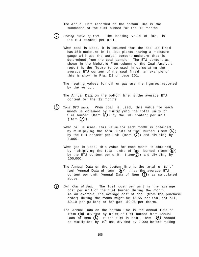
The Annual Data recorded on the bottom l i n e is the summation of the f ue l burned f o r the 12 months.
Heating Value of Fuel. The heat ing value of f u e l is the BTU content per u n i t .
When coal is used, it is assumed t ha t the coal as f i r e d has 15% mois ture in i t , but p lan ts having a mois ture gauge w i l l use the actua l percent moisture t h a t is determined from the coal sample. The BTU content as shown in the Mois ture Free column of the Coal Ana lys is repor t is the f i g u r e to be used in c a l c u l a t i n g the average BTU content of the coal f i r e d ; an example of t h i s is shown in F i g . D2 on page 101.
The heat ing values f o r o i l or gas are the f i g u r e s repor ted by the vendor.
The Annual Data on the bottom l i n e is the average BTU content f o r the 12 months.
Total BTU Input. When coal is used, t h i s va lue f o r each month is obta ined by m u l t i p l y i n g the t o t a l u n i t s of f u e l burned ( I tem ) by the BTU content per u n i t ( I t e m ) .
When o i l is used, t h i s value f o r each month is ob ta ined_ by m u l t i p l y i n g the t o t a l u n i t s of f u e l burned ( I tem ) by the BTU content per u n i t ( I tem ) and d i v i d i n g by 1,000.
When gas is used, t h i s value f o r each month is obta ined by m u l t i p l y i n g the t o t a l u n i t s of f u e l burned ( I tem ) by the BTU content per u n i t ( I tem ) and d i v i d i n g by 100,000.
The Annual Data on the bottom l i n e is the t o t a l u n i t s of f u e l (Annual Data of I tem ) t imes the average BTU content per u n i t (Annual Data of Item ) as c a l c u l a t e d above.
Unit Cost of Fuel. The f u e l cost per u n i t is the average cost per u n i t of the fue l burned dur ing the month. As an example, the average cost of coal (from the purchase order) dur ing the month might be $5.55 per t o n ; f o r o i l , $0.10 per g a l l o n ; or f o r gas, $0.06 per therm.
The Annual Data on the bottom l i n e is the Annual Data of I t em d i v i ded by u n i t s of f u e l burned from Annual Data of Item . If the f ue l is c o a l , I tem should be m u l t i p l i e d by 106 and d iv ided by 2,000 before making
105

the d i v i s i o n . I f the fue l i s o i l , m u l t i p l y by 103
and i f the fue l is gas, d i v i s i o n can be made d i r e c t l y .
Fuel Cost for the Month. When burning c o a l , the fue l cost f o r the month is c a l c u l a t e d by d i v i d i n g the t o t a l f ue l burned by 2,000 and m u l t i p l y i n g the fue l cost per t o n . For example:
This f i g u r e is c a r r i e d to the nearest d o l l a r , so the amount recorded would be $54,113.
The cost of o i l f o r the month w i l l be the t o t a l number of ga l l ons o f o i l m u l t i p l i e d by the cost per g a l l o n .
Item x 103 x
The cost of gas f o r the month w i l l be the t o t a l amount as b i l l e d monthly by the gas company.
I t em x Item
The Annual Data on the bottom l i n e is obta ined by t o t a l i n g the 12 monthly c o s t s .
System Capacity. The capac i t y of the system is the t o t a l volume of water in the system. This may be known from the amount o f water requ i red in the i n i t i a l f i l l and a f t e r f u r t h e r b u i l d i n g add i t i ons are made to the system. This can a lso be c a l c u l a t e d from the known length and s ize of the d i s t r i b u t i o n l i n e s and the water volume of the heat exchangers and genera to rs . The volume should be repor ted to the nearest thousand pounds.
Example:
683,060 lbs should be repor ted as 683,000 lbs
The Annual Data recorded on the bottom l i n e is the average of the system's capac i ty f o r the 12 months. (The capac i ty of these systems is expected to be constant but sometimes b u i l d i n g a d d i t i o n s are made to these systems. This accounts f o r the need f o r c a l c u l a t i n g an average.)
106

Make-up Water. Make-up water as read from the water meter is usua l l y measured in g a l l o n s , is recorded on the mechanical d a i l y log (form 175A), is t o t a l e d f o r the month, and is converted to pounds by m u l t i p l y i n g ga l l ons by 8 .33.
An example i s :
4,430 gal x 8.33 = 36,900
I f the water meter reads in cubic f e e t , the m u l t i p l i e r is 6 2 . 4 , ra ther than 8 .33 , to convert cubic f ee t to pounds.
The Annual Data on the bottom l i n e is the summation of the t o t a l of the pounds of make-up water used dur ing the 12 months.
Percent Make-up. Percent make-up per day is c a l c u l a t e d from the pounds of make-up water d i v ided by the number of days dur ing which the make-up was measured and then d i v i ded by the system capac i ty ( I tem ) and then m u l t i p l i e d by 100 o r :
As an example:
Percent make-up is recorded to the second decimal p lace ; in t h i s case, the percent make-up f o r the month would be recorded as 0.17%.
The Annual Data on the bottom l i n e is ca l cu la ted by d i v i d i n g the t o t a l make-up water (Annual Data of I t e m ) by the number of days dur ing which make-up was measured and by the average system capac i ty (Annual Data of I t em ) and m u l t i p l y i n g by 100.
Boiler Efficiency. The percent b o i l e r e f f i c i e n c y is c a l c u l a t e d as f o l l o w s :
107

The Annual Data on the bottom line is determined by the above formula using the Annual Data figures for Item and Item and is recorded to one decimal place.
See Example on Page 28.
108

D.3 Report PH 188, Water and E l e c t r i c i t y ( F i g . D4)
The procedures f o r p r e p a r i n g form PH 188 are d iscussed below in the o r d e r o f the numbers on the f o r m .
(1) Gallons of Water Purchased. The gallons of water purchased i s taken d i r e c t l y f rom the month ly b i l l . I f the b i l l i n g i s i n cub i c f e e t , i t must b e m u l t i p l i e d by 7 .5 to o b t a i n the t o t a l g a l l o n s . The cos t i s t h a t shown on the wa te r b i l l .
(2) Gallons of Water Pumped. The g a l l o n s of water pumped is the t o t a l recorded f rom the wate r meter as hav ing been pumped.
(3) Gallons of Water Softened. Th is q u a n t i t y is the t o t a l g a l l o n s of wa te r recorded f rom the water meter as hav ing been s o f t e n e d .
(4) Demand (KW and Pounds of Steam per Hour). If e lec t r i ca l energy is purchased, the demand as shown on the month ly e l e c t r i c a l b i l l shou ld b e recorded . I f e l e c t r i c a l energy is g e n e r a t e d , the ins tan taneous maximum demand f o r the month i s r eco rded .
For the demand pounds of s team, the maximum pounds of steam generated f o r any g iven hour f o r each month of the year shou ld be reco rded .
(5) Electrical Energy Purchased. The e l e c t r i c a l energy (KWH) i s t r a n s f e r r e d d i r e c t l y f rom the e l e c t r i c a l b i l l .
(6) Total Cost. The t o t a l cos t of e l e c t r i c i t y is taken d i r e c t l y f rom the e l e c t r i c i t y b i l l .
(7) Electrical Energy Generated. The to ta l generated e l e c t r i c a l energy recorded on form PH 175 should be reco rded .
109
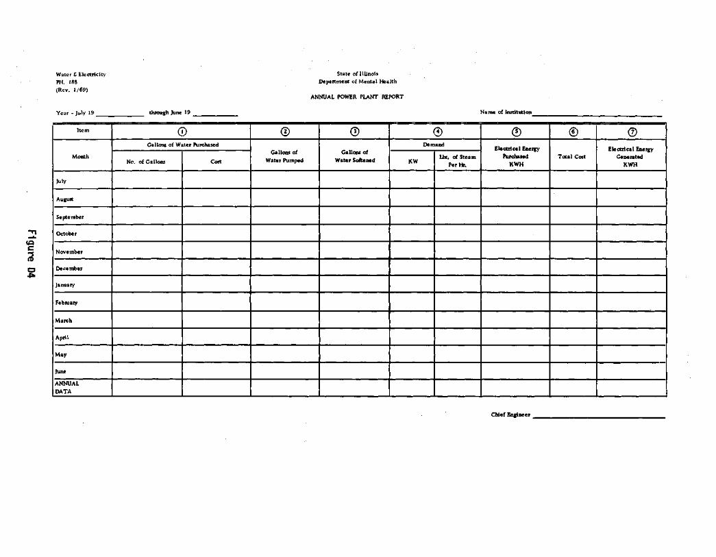

APPENDIX E. HOW TO CALCULATE DEGREE DAYS
Degree days a re the number o f degrees o f t e m p e r a t u r e t h a t have to be supp lemented by some e x t e r n a l means to m a i n t a i n an average t e m p e r a t u r e o f 65 degrees F a h r e n h e i t .
Degree days a re r e c o r d e d f r o m J u l y 1 to June 3 0 , o r f o r the f i s c a l y e a r . For examp le , degree days r e c o r d e d f o r J u l y 1 , 1969, t o June 3 0 , 1970, n o r m a l l y wou ld be r e f e r r e d to as the h e a t i n g season o f f i s c a l 1970.
Degree days a r e r e c o r d e d d a i l y on PH 175 and mon th l y on PH 176. The a c c u m u l a t i v e t o t a l degree days f o r t he month a r e r e c o r d e d on PH 176 t h u s :
Degree Days: T h i s Month 1,119 To Date 3 ,176
To c a l c u l a t e degree d a y s , you must know the h i g h e s t t e m p e r a t u r e o f the day and the lowes t t e m p e r a t u r e o f the day . C a l c u l a t e as f o l l o w s :
Example A: High t e m p e r a t u r e 6 2 ; low t e m p e r a t u r e 7
Add : 62 + 7 69
D i v i d e by 2: 69 ÷ 2 =34.5
S u b t r a c t f r o m 65 : 65 — 34 .5 =30 .5 degree days
Example B: High t e m p e r a t u r e 3 7 ; low t e m p e r a t u r e —15
Add: 37 + ( -15) = 22
D i v i d e b y 2 : 2 2 ÷ 2 = 1 1
S u b t r a c t f r o m 65 : 65 — 11 =54 degree days
Example C: High t e m p e r a t u r e —8; low t e m p e r a t u r e —22
Add: ( -8 ) + ( -22 ) = - 3 0
D i v i d e by 2: ( -30 ) ÷ 2 = - 1 5
S u b t r a c t f r o m 65 : 65 — (—15) =80 degree days
Example D: High t e m p e r a t u r e 6 8 ; low t e m p e r a t u r e 62
Add: 6 8 + 6 2 = 1 3 0
D i v i d e b y 2 : 130 ÷ 2 = 6 5
S u b t r a c t f r o m 65 : 6 5 — 6 5 =0 degree days
111

APPENDIX F. HOW TO ESTIMATE AIR CONDITIONING LOADS
In order to approximate the tons of a i r c o n d i t i o n i n g requ i red , the amount of the space (square f e e t , designated as A) to be a i r cond i t ioned must be known. Then reference should be made to the f o l l o w i n g tab le which ind ica tes the a i r c o n d i t i o n i n g requirements (designated B) fo r p a r t i c u l a r types of b u i l d i n g s employed fo r d i f f e r e n t uses.
Est imated requirement (B) Bu i ld ings i n BTU's/hr /sq f t
Apartment-Hotels 25 Department Stores 50 O f f i ces 45 Doctor Of f i ces 50 L i b r a r i e s 60 Drug Stores 70 Barber and Beauty Shops 75 Food Stores and Taverns 80 Theaters 90 Restaurants 120
As an example, 4000 sq ft of o f f i c e s would r e q u i r e :
Reference should be made to the f o l l o w i n g tab le to ob ta in a cost es t ima te :
Cost / ton
Ind i v idua l room window un i t s $1000 Package u n i t , i nc lud ing coo l ing tower $1500 Centra l system, i n c l u d i n g duct work $2000
112

APPENDIX G. ELEVATED STORAGE TANK DATA
Capac i t y Year Ca thod ic Year 1ns t i t u t i o n Number (gallons) b u i l t p r o t e c t i o n p a i n t e d
A d l e r Zone Center N A l t o n S t a t e H o s p i t a l 1 250,000 1939 Yes 1966 Anna S t a t e H o s p i t a l 1 400,000 1948 Yes 1959 Bowen C h i l d r e n ' s Center N Chicago S t a t e H o s p i t a l 1 500,000 1948 Yes 1954 Dixon S t a t e School 1 500,000 1916 No 1958 East Mo l i ne S ta te H o s p i t a l 1 300,000 1949 Yes 1969
( i n s i d e ) 1949 E l g i n S t a t e H o s p i t a l 1 500,000 1938 Yes 1954
1 100,000 1931 Yes 1954 Fox C h i l d r e n ' s Center N Galesburg S t a t e Research
H o s p i t a l N J a c k s o n v i 1 l e S t a t e H o s p i t a l 1 500,000 1953 No 1953 Kankakee S t a t e H o s p i t a l 1 500,000 1953 No 1958 L i n c o l n S t a t e School Annex 1 150,000 1930 No 1964 L i n c o l n S t a t e School Main 1 500,000 1968 No 1968 McFar land Zone Center N Madden Zone Center N Manteno S t a t e H o s p i t a l 1 250,000 1953 Yes 1967 Medica l Center Complex N Mental Hea l t h Center 2 1,000 (each) 1913 No Unknown Meyer Zone Center N Murray C h i l d r e n ' s Center N Peor ia S t a t e H o s p i t a l 1 300,000 1964 Yes 1964
1 500,000 1963 No 1963 Read Zone Center N S e c u r i t y H o s p i t a l N S inger Zone Center N T i n l e y Park 1 500,000 1952 Yes 1961 Z e l l e r Zone Center N
N = None
113