guiding in plasma channel
TRANSCRIPT
Laser wake-field acceleration and optical guiding in a hollow plasma channel
T. C. Chiou and T. Katsouleas Department of Electrical Engineering-Electrophysics, University of Southem California, Los Angeles, California 90089-0484
C. Decker and W. El. Mori University of Califooraia, Los Angeles, California 90024
J. S. Wurtele and G. Shvets Massachusetts Institute of Technology, Cambridge, Massachusetts 02139
J. J. Su National Central University, Taiwan, Republic of China
(Received 30 March 1994; accepted 15 September 1994)
The accelerating and focusing wake fields that can be excited by a short laser pulse in a hollow underdense plasma are examined. The evacuated channel in the plasma serves as an optical fiber to guide the laser pulse over many Rayleigh lengths. Wake fields excited by plasma current at the edge of the channel extend to the center where they may be used for ultrahigh gradient acceleration of particles over long distances. The wake field and equilibrium laser profiles are found analytically and compared to two-dimensional (2-D) particle-in-cell (PIG) simulations. Laser propagation is simulated over more than ten Rayleigh lengths. The accelerating gradients on the axis of a channel of radius C/C+, are of order of one-half of the gradients in a uniform plasma, For present high-power lasers, multi-GeVlm gradients are predicted. 0 1995 American Institute of Physics.
1. INTRODUCTION
Recent advances in short pulse laser technology”* offer the possibility of ultrahigh gradient acceleration of particles in laser-driven plasma wakes.3t4 Subpicosecond 10 TW pulses can generate acceleration gradients of order 10 GeV/m in a plasma of density -lot7 cme3; however, the acceleration distance is severely limited because the Ray- leigh lengths of such pulses are typically only a few milli- meters. Thus it has been widely recognized that some form of optical guiding is needed. Several approaches to this prob- lem have been previously discussed. In this article we ana- lyze a new scheme based on propagating a short laser pulse in a hollow channel embedded in an otherwise homogeneous underdense plasma.5 This scheme provides optical guiding of the laser pulse and optimal wake-field profiles for accelerat- ing particles.
Several approaches to optical guiding have been previ- ously discussed. In relativistic self-focusing the relativistic quiver motion of plasma electrons in the laser field6 causes a reduction of the index refraction on axis. Above a threshold power this mechanism provides optical guiding of the main body of the pulse. However, one-dimensional (1-D) theory7 and two-dimensional (Z-D) simulation?lo predict that the leading edge of the pulse will not be well guided. This sug- gests that roughly the front c/w,, of the pulse etches or dif- fracts away each Rayleigh length. To overcome this problem one can use a laser pulse that is very wide in the front and narrow in the back.’ This makes the Rayleigh length at the front sufficiently long.
A second approach to optical guiding is to confine the laser in a preformed channel in the plasma. A version of this was proposed several years ago by Tajima” known as the plasma fiber accelerator. In this scheme a long laser pulse
propagates down a rippled vacuum channel in an overdense plasma. Since the laser is evanescent in overdense plasma, this was supposed to act as a slow wave conducting struc- ture. However, resonance absorption at the overdense chan- nel edge can quickly degrade the laser (similar effects have been seen in simulations OF related laser acceleration schemes involving overdense plasma’*). More recently, opti- cal guiding in a tailored density channel has been investi- gated theoretically and numerically by Sprangle and co-workers9 The density on axis is taken to be the usual density for wake excitation (i.e., no is chosen such that nclw, matches the laser pulse length), and the density rises parabolically with radius to confine the laser. They found that the accelerating wake is still coherent in the channel. A re- cent experiment by Durfee and Milchberg has already dem- onstrated guiding of low-intensity laser light in a plasma channel. l3
Here we propose a scheme for wake-field acceleration in a hollow underdense plasma,5 For simplicity, a “square” transverse plasma density profile with a step function plasma/vacuum interface will be assumed. In Sec. VI we discuss the effect of a boundary with nonzero thickness, and in the Appendix we analyze the general case for an arbitrary plasma profile. Since the index of refraction (6 = dv) in underdense plasma is less than the index in the evacuated central region (&= 1), the laser can be confined as if it were in an optical fiber. The short laser pulse drives a plasma wake in the plasma at the edge of the hollow channel. The electromagnetic fringe fields of the wake ex- tend to the center of the channel, enabling focusing and ac- ceIeration of particles down the axis. This scheme differs from the plasma fiber accelerator in two important respects. First, since the plasma is underdense, resonance absorption
310 Phys. Plasmas 2 (I), January 1995 1070-664X/95/2( I)/31 O/9/$6,00 0 1995 American Institute of Physics
Downloaded 04 Mar 2003 to 128.32.210.150. Redistribution subject to AIP license or copyright, see http://ojps.aip.org/pop/popcr.jsp
of the driving pulse at the channel walls is avoided. Second, the accelerating fields arise from a plasma wake rather than from a transverse magnetic (TM) component of the laser mode. The scheme differs from the parabolic channel of Sprangle et ~1.~ in that the channel here is completely evacu- ated, so that the wake fields arise from surface currents at the channel edge rather than density bunching at the channel axis.
The main objective of this work is to show that a large amplitude wake can be generated over long distances by an optically guided laser pulse in a hollow channel. Although this same goal can be achieved in a parabolic channel, there are several reasons for considering the hollow channel case. First, it will be seen that the mode structure of the wake field in a hollow channel is ideal for accelerating high quality beams. The axial field component is independent of trans- verse position, so particles at different radii gain energy at the same rate minimizing their energy spread. The focusing wake is weak and linear, helping to preserve the emittance of the beam. For a given plasma density, the wavelength is longer, increasing the bunch acceptance for injected beams. There may be other advantages to hollow channels. In sepa- rate work we have found that laser pulses in hollow channels may be less subject to instabilities such as laser hosing and Raman scattering. The absence of plasma in the beam path eliminates any scattering of beam particles by plasma nuclei, although this is generally very minor. Finally, a hollow plasma channel may be easier to realize experimentally than a channel with a precisely tailored density profile.
In Sec. II we analyze the plasma mode excited in a hol- low plasma. In Sec. III we analyze the laser mode. The wake amplitudes are estimated in Sec. IV and compared to 2-D particle-in-cell (PIC) simulations in Sec. V.
II. PLASMA SURFACE MODE-FRINGE FIELD ACCELERATOR
We now consider the normal wake-field modes that can be excited in a plasma with a hollow channel. Assume that the laser pulse propagates down the z-direction. The channel supports a surface plasma wave. The mode structure follows from Maxwell’s equations,
VXE=-$J3,
VXB=yj+f&E,
(14
j= - enOv, (2) where no is the unperturbed plasma density, v is the per- turbed electron velocity. The equation of motion for a cold stationary plasma is
& v= z (E-Vf ), (3)
where E is the electric field of a plasma wave, f is the aver- aged ponderomotive potential divided by e; f= ($rz V&)/e, Vw=eE,lmcoo, and E, is the amplitude of the laser profile
to be found in Sec. III. Equation (3) is valid for V,,&c41. Combining Eqs. (la) and (lb) and using Eqs. (2) and (3) gives the wave equation,
2 2 2
V(P..E)-V’E+~E+~~E=~V~, (4)
where o:=4rnoe2/m. The normal wake-field modes now can be found from Eq. (4) by setting f=O.
We analyze Eq. (4) in both slab and cylindrical geom- etry. First in slab geometry, Fourier analyzing (4) gives the dispersion relations in the plasma and the channel,
w2 - C2k2 - C2k2 = 0 z .L in channel, 64
(02--~)(02--~--2kZ2--2k~)=0 in plasma. W-9
In plasma, the first term is the longitudinal mode (VXE=O) while the second term is the transverse mode (V.E=O). We look for surface modes which are transverse, so k: becomes -gL both in the channel and in the plasma,
~~~ = dw in channel, (6a)
Key= Jn in plasma. (6b)
The mode in the channel is transverse, so the mode in the plasma must also be transverse. Otherwise V X E would not be continuous as required by the fact that there are no linear surface currents. Since the laser is symmetric with respect to the z-axis, the ponderomotive force is symmetric and we assume symmetric solutions for the wake fields. The wake- field solutions for E inside the channel (Iy 1 <a, where 2a is the channel width) are
E,(y,z,t) =A cosh( Klcy)ei(kzz-wt),
E,(y,z,t) = B sinh( KI,y)ei(kzz-ot),
and in the plasma (1~1 >a)
(74
(7b)
E,(Y ,z,t) = Ce -K~p(lYI-a)ei(k,z-wtf , @a)
E,(y,z,t)=De -~lp(l~I-a)ei(k,z-ot) @b) where A, B, C, D are as yet undetermined constants. Using V.E=O in the plasma and in the channel, the continuity of E tangential =E, and the continuity of Dnormal= EE, , where E= 1 - oi/ti2 in the plasma and E= 1 in the channel, we obtain the dispersion relation,
tit Kd) - KlC
Klp=dj (9)
We are interested in the mode with phase velocity u~=( w/k,) WC (since up will be determined by the group velocity of the laser pulse =c as discussed in the next sec- tion). Then from Eq. (6) ~~~a=oa/y,u~-=S 1 [where yp( 1 - v2,1c2) -“2], so that the dispersion relation simpli- fies to
(10)
Phys. Plasmas, Vol. 2, No. 1, January 1995 Chiou et al. 311 Downloaded 04 Mar 2003 to 128.32.210.150. Redistribution subject to AIP license or copyright, see http://ojps.aip.org/pop/popcr.jsp
where k,,= wPIc. Note that in the electrostatic approximation (c-w or v,ec), Eqs. (6) give K~~~K,+~~~, and the dis- persion relation (9) becomes
- tanh( k,a) = I- o%/w2. 011
For an infinite half-space, a+~, o approaches the well- known result’4 tip/& For the high phase velocity modes (u~=c), the field structure is given explicitly [from Eqs. (7) and (8) and V-E=O] by
(124
&@0-‘Z~C)l= - : 23,) (12’4
in the channel, and
~,(y,z,~)=Ae-~p(lYl-~),-i~[~-(z~~~l,
(124
in the plasma. Thus the accelerating field E, is nearly uni- form across the channel, while the focusing force q(E,+u,B,)=q[l-(u,v,/c’)]E, is nearly linear in y, where u, is the longitudinal partrcle velocity. Such a field structure is nearly optimal for accelerating particles with minimum energy spread and emittance growth. However, the magnitude of the focusing force approaches zero for relativ- istic particles and wakes so that some external focusmg may be required.
In cylindrical geometry, we assume a solution of the form E=Eeii(Yt-k’) with E=E,E+E,? and no azimuthal dependence for each field component. Then, Eq. (4) can be decomposed into r and z components. By assuming o/k-c the solutions in each region can be found.
In the channel,
ikA E,(r,z,t) = 2 re-‘(mf-kZ),
where A is an arbitrary constant. In the plasma,
KoCkpd E,(r,z,t) =A - e -i(w-kz)
Ko(kpal I
ik AKl(k,r) E,(r,z,t)= - -
k, Ko(k,4 e-i(or-kz)
,
(144
(14b)
where the K’s are modified Bessel functions of the second kind. The dispersion relation follows once again from Eqs. (13) and (14) and the continuity of E, and EE, across the channel boundary,
(15)
Note that the accelerating field is independent of r while the focusing field E,- B e vanishes for u ‘p-) c.
III. LASER MODE
In this section we obtain the equilibrium transverse pro- file of the laser in a fixed hollow channel. We assume the laser pulse is long enough that it can be considered mono- chromatic (L+oo/c) and weak enough not to distort the channel (V,,,/c~ 1). The pulse is assumed to be nonevolving (i.e., instabilities and pump depletion are neglected).
The mode structure of the laser in the hollow plasma is well approximated by the mode structure in an optical fiber with refractive index n , = 1 inside and pz2 = Gg@i outside. Because the laser field is maximum at the channel center, we look for the fundamental TE mode solution of Maxwell’s equations. In slab geometry, this is’s
E,= E. cos(k,y)e-‘kz, lyl~a, E. cos(k,u)e-p”~l-a’e-ikz, lyf”a, (16)
where k;=kfj-k=, p2=k2-k&i and ko=WOIc, w. is the frequency of the laser pulse. Applying the continuity of H, gives the characteristic equations
p = k, tan( k,a ) , (174
p2+k;=k;. (17b)
In cylindrical geometry, the appropriate solutions of Maxwell’s equations are the so-called HE,, model6 in an optical fiber which in this case, because n t -n,+l, can be approximated by the linearly polarized mode LP,, . choosing the laser pulse to be polarized in the x direction, the field is
[ Eofo(hr)evikz, r<u, E,=
EO J0(ha)
Ko(w) KO(qr)e-ikz, r>a,
where h2= ki-- k2, q2= k2 - kin;, and Jo is the Bessel func- tion of the first kind and K. is the modified Bessel function of the second kind. The characteristic equation becomes
h2+q2=k;. (19b)
Equations (17) and (19) can be solved numerically for k, and h as functions of the channel radius, The results are plotted in Fig. 1. These results allow us to determine the equilibrium laser profile [Eqs. (16) or (18)] for diffraction-free propaga- tion of the laser down the channel (Fig. 2). We comment that the group velocity of the light pulse in the channel can be obtained from the dispersion relation [Eqs. (17) or (19)]. We find that v,Ic = k/k, for either geometry. For example, for k,a = 1 in cylindrical geometry, u&c = 1 - 0~/2.080~ is very close to the homogeneous plasma result 1 - 0$/20~.
IV. AMPLITUDE OF THE ACCELERATING GRADIENT
To find the amplitude of the acceierating gradient, we must keep the driving term Vf in Eq. (4). We assume that E is a function of only .$=z--ct and y; this implies that E is nonevolving and that pump depletion and laser instabilities are neglected. Fourier transforming in 15 we obtain first in slab geometry the y and z components of Eq. (4),
312 Phys. Plasmas, Vol. 2, No. 1, January 1995 Chiou et al.
Downloaded 04 Mar 2003 to 128.32.210.150. Redistribution subject to AIP license or copyright, see http://ojps.aip.org/pop/popcr.jsp
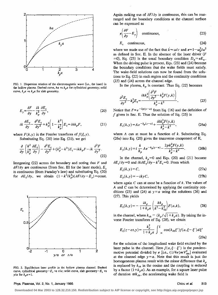
FIG. 1. Dispersion relation of the electromagnetic wave (Le., the laser) in the hollow plasma. Dashed curve, ha vs k,a for cylindrical geometry; solid curve, k,a vs k,a for slab geometry.
2
ik$-$+k; E,= ikk,F,
where F(k,y) is the Fourier transform of f( 5,~). Substituting Eq. (20) into Eq. (21), we get
(20)
(21)
(22)
Integrating (22) across the boundary and noting that F and dF/dy are continuous (from Sec. III for the laser mode), E, is continuous (from Faraday’s law) and substituting Eq. (20) for dE,lJy, we obtain (I- k2/k~)(dFldy - EJ =const.
y/a or r/a
FIG. 2. Equilibrium laser profile in tbe hollow plasma channel. Dashed curve, cylindrical geometry-E, vs r/a: solid curve, slab geometry-E, vs ylu for k,a=l.
Again making use of 6’Fldy is continuous, this can be rear- ranged and the boundary conditions at the channel surface can be expressed as
dF E ay- i i EY continuous,
E, continuous, (24)
where we made use of the fact that k- o/c and g= 1- e$/w2 as defined in Sec. II. In the absence of the laser driver (F =0), Eq. (23) is the usual boundary condition D,=EE,. When the driving pulse is present, Eqs. (23) and (24) become the boundary conditions that the wake fields must satisfy. The wake-field solutions can now be found from the solu- tions to Eq. (22) in each region and the continuity conditions (23) and (24) across the channel edge.
In the plasma, kp is constant. Thus Eq. (22) becomes 2
$-k;Ez= ikk; $- k;F(y,k)
k;-k2 * (25)
Notice that F=e -2p(y-a) from Eq. (16) and the definition of f given in Sec. II. Thus the solution of Eq. (25) is
E,(k,y)=Ae-k~(“-a)+ ikk;F(y,k)
k;-k2 ’ (264
where A can at most be a function of k. Substituting Eq. (26a) into Eq. (20) gives the transverse component of E,
k E (k y)=i -Ae-kp(Y-“I-
W;FW Y ’
kP k;-k” . W-d
In the channel, k,=O and Eqs. (20) and (21) become aE,ldy =0 and ikdE,ldy - k2E,=0. From which
E,(k,y) = C, (274
E,(k,y) = - iky C, G’b)
where again C can at most be a function of k. The values of A and C can be determined by applying the continuity con- ditions (23) and (24) at y =a using the solutions (26) and (27). This yields
(28)
in the channel, where kch = ( kp / dm). By taking the in- verse Fourier transform of Eq. (28), we obtain
k; E,(z-c~,Y)= ~+k cos&d’Ma,5- 5’bW
P m
(294 for the solution of the longitudinal wake field excited by the laser pulse in the channel. Here f(a, t-- 5’) is the pondero- motive potential divided by e [i.e., (1/4e)mV&] evaluated at the channel edge y = a. Note that this result is just the homogeneous plasma result with the minor difference that kp is replaced by kch in the cosine and the coupling is reduced by a factor (1 +k,a). As an example, for a square laser pulse of duration dkch, the accelerating wake field is
Phys. Plasmas, Vol. 2, No. 1, January 1995 Chiou et al. 313
Downloaded 04 Mar 2003 to 128.32.210.150. Redistribution subject to AIP license or copyright, see http://ojps.aip.org/pop/popcr.jsp
sin[k,h(z-ct)] y=ll
For completeness, we include the solution for E, excited in the plasma. Inverse Fourier transforming Eq. (26a) and using the values of A gives k2 E,(z-cta)= k
P i 5, cos(kt,S’)f(a,5-5’)
Xd&-’ e-$Jk-4+p s 5 P
cos(k,[‘) -z
Notice that the first term is the surface mode response at frequency a& ; while the second term is the body mode in the plasma responding at the usual plasma frequency tip, We see that the body mode is generally small; it is zero
the surface (y = a), peaks at radius of ;;/(2p-k )]ln(2plk > +a and decays away “,t large y.
In cylgdrical gelmetry, we assume there is no azimuthal dependence, Le., d/+=0. Then following the same reason- ing as in slab geometry, we determine the boundary condi- tions to be
continuous,
EZ continuous.
The r and z components of Eq. (4) are (3Ob)
(314
The solutions in each region are
ikkz E,Uw)=AK,,(k,r)+ k2_k2 F(r,k),
P
k; d Er(kr) = g-q~ dr F(r,kj + E AK,(k,rj
P k (32b)
P
in the plasma; and
E,(r,k) = C, (334
Wb)
in the channel. From Eqs. (32), (33), and (30), we can evalu- ate C and hence the value of E,(r,k) in the channel,
- ikk;. E,(r,k)= -pq- F(d),
w
where
(34)
16,
spy/c a
0 40 50 60
yJ/c
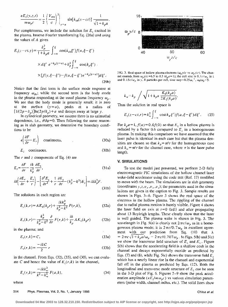
FIG. 3. Real space of hollow plasma electrons (w,yfc vs w,:/c). The chan- nel extends from w,y/c =6.5 to 8.5 (k,a = 1); the cell size is 0.1 C/W, in :. and O.l5c/w, in y. 8 particles per cell, time step=O.25&,‘, wdw,>=5.
k,,=k, / x/m+
Thus the solution in real space is
E,(z-ct,r)=k;, 5
costk,~‘jf(a,~-5’)d~‘. (35) -r
For k,a = 1, f(a) = 0.6f( 0) so that E, in a hollow plasma is reduced by a factor 0.6 compared to E, in a homogeneous plasma. In making this comparison we have assumed that the laser pulse is identical in each case but that the plasma den- sities are chosen so that k,= n/r for the homogeneous case and k,=dr for the channel case, where 7 is the laser pulse length.
V. SlMULATIONS
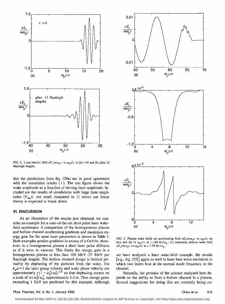
To test the model just presented, we perform 2-D fully electromagnetic PIC simulations of the hollow channel laser wake-field accelerator using the code ISIS (Ref. 17) modified to move with the beam. The simulations are in slab geometry (coordinates y ,z, u, , u, ,u,); the parameters used in the simu- lations are given in the caption to Fig. 3. Sample results are shown in Figs. 3-6. Figure 3 shows the real space of the electrons in the hollow plasma. The rippling of the channel due to radial plasma motion is barely visible. Figure 4 shows the laser field on axis at t=O (left) and after propagating about 13 Rayleigh lengths. These clearly show that the laser is well guided. The plasma wake is shown in Fig. 5. The wavelength in Fig. 5(a) is clearly not 27~1~~ as in a homo- geneous plasma mode; it is 2rc/0.7wp in excellent agree- ment with our prediction from Eq. (10) that A = Zrrc~~lw, = 2rrcl0.707~~. In Figs. 5(b) and5(cj we show the transverse field structure of E, and E, . Figure 5(b) shows that the accelerating field is a shallow cash in the channel and decays exponentially outside as predicted by Eqs. (7) and (8), while Fig. 5(c) shows the transverse field E, which has a nearly linear rise in the channel and exponential fali off in the plasma as predicted by Eqs. (12). Both the longitudinal and transverse mode structure of E, can be seen in the 3-D plot of Fig. 6. Figures 7-9 show the peak accei- eration amplitude (e E,ltn wpc) vs various simulation param- eters (pulse width, channel radius, etc.). The solid lines show
314 Phys. Plasmas, Vol. 2, No. 1, January 1995 Chiou ef al.
Downloaded 04 Mar 2003 to 128.32.210.150. Redistribution subject to AIP license or copyright, see http://ojps.aip.org/pop/popcr.jsp
- t=O eE, mcopc .
0
-1.51 0 (a)
. .-
- after 13 Rayleigh eE, lengths mf.!$c .
-1.51 I 40 45 50 55 60 (f.4 O,Z/C
FIG. 4. Laser electric field eE,lmo,c vs w&c at (a) t=O and (b) after 13 Rayleigh lengths.
that the predictions from Eq. (29a) are in good agreement with the simulation results (+). The last figure shows the wake amplitude as a function of driving laser amplitude. In- cluded are the results of simulations with large laser ampli- tudes (V&c not small compared to 1) where our linear theory is expected to break down.
Vi. DISCUSSION
As an illustration of the results just obtained, we con- sider an example for a state-of-the-art short pulse laser wake- field accelerator. A comparison of the homogeneous plasma and hollow channel accelerating gradients and maximum en- ergy gain for the same laser parameters is shown in Table I. Both examples predict gradients in excess of a GeV/m. How- ever, in a homogeneous plasma a short laser pulse diffracts as if it were in vacuum. This limits the energy gain in a homogeneous plasma to less than 100 MeV (37 MeV per Rayleigh length). The hollow channel design is limited pri- marily by dephasing of the particles from the wake. For k,a = 1 the laser group velocity and wake phase velocity are approximately c( 1 - wi/wi) I” so that dephasing occurs on a scale of WC&O;, approximately 1.2 m. Thus energy gains exceeding 1 GeV are predicted for this example. Although
50 55 60 65 (4 opz/c
0 4 a 12 (b) OpYk
0 4 a 12 (d OpY/C
FIG. 5. Plasma wake fields (a) accelerating field eE,/mopc vs o,z/c on axis and (b) vs o,ylc at z=60.8c/o,; (c) transverse plasma wake field eEylmw,c vs w,yfc at z=59.8cfw,,
we have analyzed a laser wake-field example, the results [e.g., Eq. (35)] apply as well to laser beat wave excitation in which two lasers beat at the normal mode frequency in the channel.
Naturally, the promise of the scheme analyzed here de- pends on the ability to form a hollow channel in a plasma. Several suggestions for doing this are currently being ex-
Phys. Plasmas, Vol. 2, No. 1, January 1995 Chiou et al. 315
Downloaded 04 Mar 2003 to 128.32.210.150. Redistribution subject to AIP license or copyright, see http://ojps.aip.org/pop/popcr.jsp
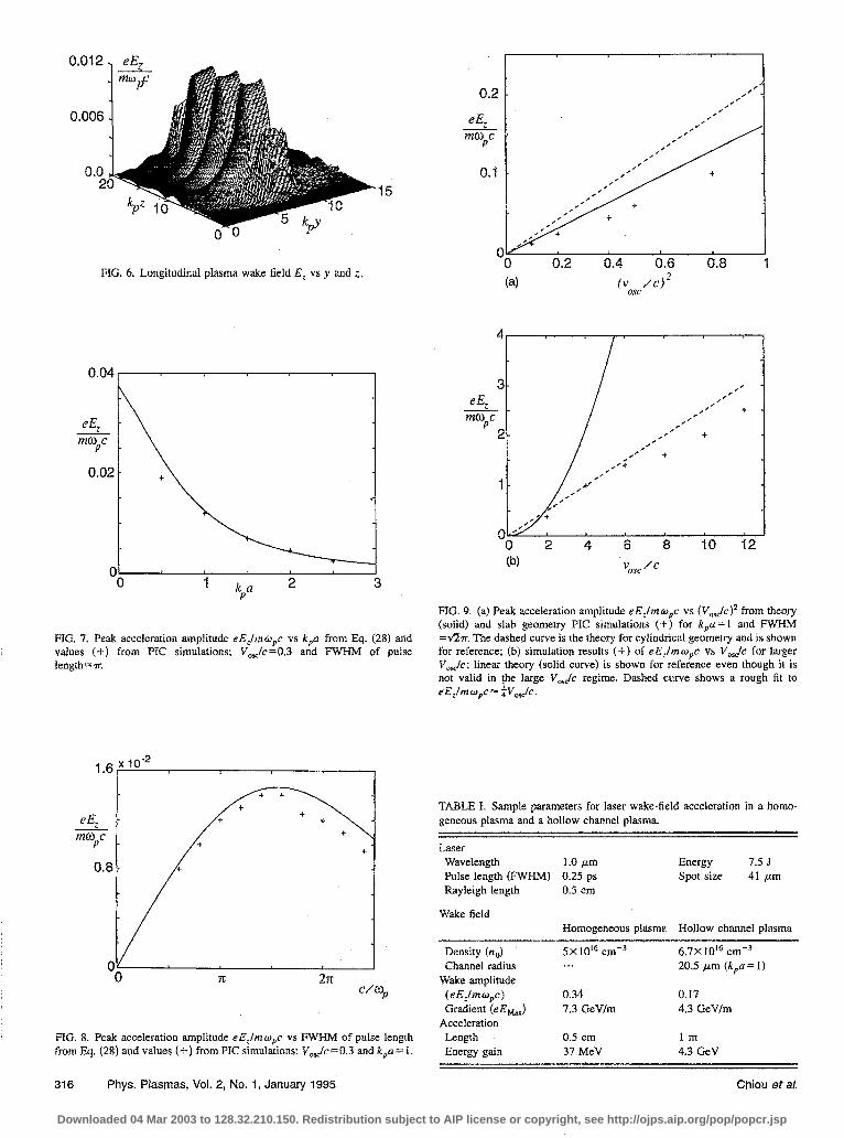
FIG. 6. Longitudinal plasma wake field E, vs y and z.
FIG. 7. Peak acceleration amplitude eE,fmwpc vs k,a from E$. (28) and values (+) from PIC simulations; V&=0.3 and FWHM of pulse length= r.
1.6
e$ mope
0.8
2n cm,
FIG. 8. Peak acceleration amplitude eE,/mwpc vs FWHM of pulse length from Eq. (28) and values (-I-) from PIC simulations: V,&=O.3 and k,a= 1.
316 Phys. Plasmas, Vol. 2, No. 1, January 1995 Chiou et al.
0 0.2 0.4 0.6 0.8
FIG. 9. (a) Peak acceleration amplitude eE,fmw,c vs (V,&C)~ from theory (solid) and slab geometry PIC simulations (+) for k,a = I and FWHM =fiv. The dashed curve is the theory for cylindrical geometry and is shown for reference; (b) simulation results (+) of eE,lmw,,c vs V&c for larger Vo&; linear theory (solid curve) is shown for reference even though it is not valid in ;he large V&c regime. Dashed curve shows a rough fit to eE,fmw,c= aV,&.
TABLE I. Sample parameters for laser wake-field acceleration in a homo- geneous plasma and a hollow channel plasma.
Laser Wavelength 1.0 pm Energy 7.5 J Pulse length (FWHM) 0.25 ps Spot size 41 pm Rayleigh length 0.5 cm
Wake field Homogeneous plasma Hollow channel plasma
Density (no) 5X lOI cmN3 Channel radius ...
Wake amplitude (eE,fmo,c) 0.34 Gradient (eEhlax) 7.3 GeVfm
Acceleration Length 0.5 cm Energy gain 37 MeV
6.7X 10’” cmo3 20.5 pm (kp = 1)
0.17 4.3 G&/m
lm 4.3 GeV
Downloaded 04 Mar 2003 to 128.32.210.150. Redistribution subject to AIP license or copyright, see http://ojps.aip.org/pop/popcr.jsp
plored. These include ionization of a gas jet with a fine wire to block the central flow of gas” or channel formation by a precursor pulse of laser” or beam energy.” Some recent laser experiments have shown evidence of self-channel for- mation and guiding.5V21 In experiments the channel edge may not be perfectIy sharp. In this case there is a resonant layer at which the local plasma frequency matches the wake fre- quency ti&. An extended analysis which allows this possi- bility is included in the Appendix. We also note that prelimi- nary simulations with finite gradient channel edges show relatively little difference in laser profile and initial wake amplitude. In these simulations, we compared a step function profile with k,a= 1 to a case with a linear ramp from k,y =0.5 to 1.5 (i.e., Ldsdge=u ). The only notable difference was that the wake fields behind the first peak in the ramped case were damped, probably due to resonant absorption in the boundary layer.
Our analysis suggests that hollow channels can be used to generate large amplitude wakes over many Rayleigh lengths using guided laser pulses. Compared to a homoge- neous or parabolic channel plasma, the wake is smaller by a factor of about 2, but it has other attractive properties for accelerators. Namely, the accelerating field is uniform across the channel; the focusing force is nearly zero and linear; the wavelength is longer and the laser guiding and peak wake amplitude are relative insensitive to the shape of the channel wall.
ACKNOWLEDGMENTS
We gratefully acknowledge useful input from David Whittum and from Bob Bingham.
Work supported by U.S. Department Of Energy Grant No. DOE-AC#DE-FGO3-92ER40745.
APPENDIX: WAKE FIELDS IN INHOMOGENEOUS PLASMA
The hollow channel analyzed in the main body of this paper is a particular case of inhomogeneous plasma which was chosen because of its conceptual simplicity and its ame- nability to analytical methods. In general, the transverse plasma density profile is not likely to be a step function, and an appropriate model for the excitation of a wake must be developed.
In this section we develop for the first time a general formalism for calculating the wake fields generated by an intense laser pulse propagating through an inhomogeneous plasma. The theory models inhomogeneities in the plane per- pendicular to the direction of propagation of the driver. A general formalism is developed and then simplified with an assumption of a stratified density profile. This calculation is applicable to various schemes of wake-field generation such as laser wake-field accelerator and plasma beat-wave accel- erator. Formally, the treatment is similar to the that of the resonant absorption of p-polarized light on an inhomoge- neous plasma slab.
This appendix derives an equation for a scalar quantity, P, rather than for the axial electric field E, as is done in the body of the paper. The convenience of using P, which will
be shown to be proportional to the magnetic field, is that P is always finite and continuous, unlike E, which becomes sin- gular in resonance absorption regions.
The equation of motion for a fluid element of a cold, initially stationary plasma, under the influence of the pon- deromotive force and the electric field generated by any in- duced plasma displacement is given in Eq. (3),
(Al)
From Poisson and continuity equations,
V-E=47$, W)
and a Fourier transform in time, we obtain
V-(E+4rij/w)=O. 644)
Here all the quantities are assumed to have a time depen- dence -exp( - iwt). Similarly, Fourier transforming Eq. (Al) and using j= -enov and Eq. (A4) gives
+( ~-?+)~~Vj-]=O~ w> Here
oio(y) =47re2no(y)lm G46)
is the spatially nonuniform equilibrium plasma frequency. Any divergence free vector is equal to a curl of another
vector, so that
- o;o(Y w2 VXP E=
1 - $o(Y l/w2 vf+
1 - o;o(YYo2 (A7)
where P is a vector proportional to magnetic field. In fact, it will be shown later that for a homogeneous plasma vector P goes to zero and the wake becomes electrostatic.
From Maxwell’s equations,
1 d2E VxVxE+
49-r dj 7at”=yqjp 648)
Combining Eq. (A8) with Eq. (A7) results in
i
VXP vxvx
Wio(Y > 1 1 - Wio(Y w2 -Vf co2 1 - o;o(y)lo2 i
=$VXP. (‘49)
Equation (A9) can be simplified to a scalar differential equa- tion in instances where the plasma has planar or azimuthal symmetry. In these limits, the outer curl in Eq. (A9) can be removed and Eq. (A9) is substantially simplified.
Case 1. For slab geometry, n =n(y), f=f(y,z), and the TM space-charge mode is excited, with P=e,P(y,z).
Case 2. For cylindrical geometry, n=n(r), f=f(r,z), and a TM wave is generated with P=e+,P(r,z).
The physical reason for this simplification is that, from the symmetry of the cylindrical and slab geometries, the
Phys. Plasmas, Vol. 2, No. 1, January 1995 Chiou et al. 317
Downloaded 04 Mar 2003 to 128.32.210.150. Redistribution subject to AIP license or copyright, see http://ojps.aip.org/pop/popcr.jsp
magnetic field becomes unidirectional. We will now concen- trate on case 1. The extension to azimuthaily symmetrical cylindrical geometry is straightforward.
By introducing P=e,P(y,z), Eq. (A9) is reduced to
(AlOj
Since the laser drivers are moving with speeds close to the speed of light, it can be assumed that all quantities of interest are functions of y and a single longitudinal variable l=z -ct. This assumes that the laser pulse is nonevolving. Equa- tion (AIO), after Fourier transforming, simplifies to
d2P dP d -ip-dy3y
-ln(l-~)++p
=iFf$ln( 1-q).
Equation (Al 1) is valid for any transverse density profile ~:~(y) including those with density discontinuities. Knowl- edge of P from Eq. (Ail) allows us to compute the electric field through Eq. (A7). For continuous density profiles Eq. (All) can be solved for P using the boundary condition
lim P(y)=O, y-2%
6412)
In a homogeneous plasma [(alay)wi(y) =0] it is evident that P=O is the only solution satisfying Eqs. (All)-(A12). This implies that the wake field in a homogeneous plasma is electrostatic.
For discontinuous density profiles (e.g., a hollow chan- nel) one must match the solutions at discontinuities. The con- ventional rule for matching the solutions at discontinuities is to find an invariant that remains continuous across the den- sity jump. Careful examination of Eq. (All) gives the con- tinuity conditions
P( y ) -+ continuous, (A13)
[g-irf) /[I-$$$-)-+continuous, (A14)
where one can show that Eq. (A14) is equivalent to demand- ing the continuity of E, and Eq. (A13) is equivalent to bal- ancing the jump in E, with the surface charge. A hollow channel can be analyzed by solving Eq. (Al 1) both inside the channel and inside the plasma and applying the continuity conditions Eqs. (Al3)-(A14).
We are now in a position to give physical meaning to the vector P. Combining Faraday’s law with Eq. (A7) and Eq. (AlO) results in
B=-i ZP. (A*3
In channels with smoothly varying plasma density, as opposed to a step function (hollow channel) profiles, reso-
nant enhancement can occur. For exampIe, the surface mode wake field described in the main text oscillates at frequency @ch = wr,/~~. Thus the surface mode can damp out quickly as it supplies energy to a resonant body mode at a location such that w,(y) ‘w,h. There exist various mecha- nisms for limiting the amplitude of the electric fieId in the resonant region (and accounting for the energy absorption), such as the crossing of the electron trajectories with conse- quent breakdown of the fluid theory and ejection of energetic electrons, electron collisions, and relativistic corrections to the index of refraction. All these are currently under investi- gation, both numerically and analytically, and will be the subject of forthcoming publications.
‘I? Maine, D. Strickland, P. Bado, and G. Mourou, IEEE J. Quantum Elec- tron. QE-24, 398 (1988).
‘C. B. Darrow, M. D. Perry, F. Patterson, and E. M. Campbell. in Advanced Acceferarion Conceprs, edited by C. Joshi, AIP Conf. Proc. 193 (American Institute of Physics, New York, 1989). p. 50.
3T. Tajima and J. M. Dawson. Phys. Rev. Lett. 43. 267 (1979). 4P. Sprangle, E. Esarey, A. Ting, and G. Joyce, in Ref. 2. p, 376: T. Kat-
souleas, W. B. Mori, and C. Darrow ibid. 193, 165 (1989); P. Sprangle, E. Esarey, A. Ting, and G. Joyce, Appl. Phys. Lett. 53, 2146 (1988): L. M. Gorbunov and V. I. Kirsanov, Sov, Phys. JETP 66. 290 (1987).
‘T. Katsouleas. T. C. Chiou, C. Decker, W. B. Mori, J. S. Wurtele, G. Shevets, and J. J. Su, in Advanced Accelerator Conceprs, edited by J. S. Wurtele, AIP Conf. Proc. 279 (American Institute of Physics, New York, 1992).
‘C. Max, J. Arons, and A. B. Langdon, Phys. Rev. Lett. 33,209 (19743; G. Schmidt and W. Horton, Comm. Plasma Phys. 9, 85 (1985); P. Sprangle, Cha-Mei Tang, and E. Esarey, IEEE Trans. Plasma Science PS-IS, 145 (1987).
7P. Sprangle, E. Esarey, and A. Ting, Phys, Rev. Lett. 64, 201 I (1990). ‘T. Katsouleas, W. 3. Mori, R. L. Williams, D. Betz, and B. Hui, in Nun-
linear Dynamics and Particle Acceleration, edited by Y. Ichikawa and T. Tajima, AIP Conf. Proc. 230 (American Institute of Physics, New York, 1991). p. 134; W. B. Mori and T. Katsouleas, Two-Dimensional Studies of the Laser Wakefield Accelerator (UCLA-IPFR. Los Angles, CA, 1989), Paper No. PPG-1529.
9P. Sprangle, E. Esarey, J. Krall, and G. Joyce, Phys. Rev. Lett, 69, 2200 (1992); E. Esarey, P. Sprangle, J. Krall, A. Ting, and G. Joyce, Phys. Fluids B 5, 2690 (1993); J, Krall, E. Esarey, P. Sprangle, and G. Joyce, Phys. Plasmas I, 1738 (1994).
“T, Antonsen, Jr. and I? Mora, Phys. Rev. Lett. 69, 2204 (1992). “D. C. Barnes, T, Kurki-Suonio, and T. Tajima, IEEE Trans. Plasma Sci.
PS-15, 154 (1987). t2T, ~Katsouleas, I, M. Dawson, D. Sultana, and Y. T. Yan, IEEE Trans. Nucl.
Sci. NS-32, 3555 (1985). 13C G. Durfee and H. M. Milchberg. Phys. Rev. Lett. 71, 2409 (1993). i4P.‘K. Kaw and J. B. McBride, Phys. Fluids 13, 1784 (1970). “Donald L. Lee, Electromagnetic Principles of Integrated Optics (Wiley,
New York, 1986). Chap. 4. 16Amnon Yariv, Optical Electronics, 3rd ed. (Holt, Rinehart, and Winston,
New York, 1985). Chap. 3. 17R. L. Morse and C. W. Nielson, Phys. Fluids 14.830 (197 1) (see Appendix
A); M. E. Jones (private communication). ‘*M. Everett (private communication). 19W B Mori C. Joshi, J. M. Dawson, D. W. Forslund, and J. M. Kindel.
Phys.‘Rev. Lett. 50, 1298 (1988). “J. Rosenzweig. 3. Breizman, T. Katsouleas, and J. J. Su, Phys. Rev. A 44,
6189 (1991); this reference and the next deal with channels in which only electrons are evacuated but ions remains,
“A. Sullivan, S. Gordon, H. Hamster, H. Nathel, and R. W, Falcone, in Short Wavelength V Physics with intense Laser Pulses Technical Digest. 1993 (Optical Society of America, Washington, DC, 1993). pp. 16-18; A. B. Barisov. Phys. Rev. Lett. 68. 2309 (1992).
318 Phys. Plasmas, Vol. 2, No. 1, January 1995 Chiou et al.
Downloaded 04 Mar 2003 to 128.32.210.150. Redistribution subject to AIP license or copyright, see http://ojps.aip.org/pop/popcr.jsp