guinier imaging plate camera g670 - xhuber
TRANSCRIPT
GUINIER IMAGING PLATE
CAMERA G670
INSTRUCTION MANUAL
HUBER Diffraktionstechnik GmbH & Co. KG Sommerstrasse 4 D-83253 Rimsting
Phone: +49 (0) 80 51/68 78 - 0 Fax: +49 (0) 80 51/68 78 - 10
eMail: [email protected]
Revision 5.0 january 2006/rfh
Program updates are available at www.xhuber.com/glob/download/
1

2
Table of Contents OVERVIEW.......................................................................................................... 5
TECHNICAL DATA .................................................................................................. 5 INSTALLATION ................................................................................................... 6
STEP 1: INSTALLATION OF THE G670 DATA COLLECTION SOFTWARE ...................................... 6 STEP 2: INSTALLATION OF THE A/D-CONVERTER BOARD .................................................... 6 STEP 3: STEPPING MOTOR CONTROLLER BOARD SOFTWARE INSTALLATION .............................. 8 STEP 4: INSTALLATION OF THE CORRECTION FILE ............................................................ 8 STEP 5: CAMERA INSTALLATION................................................................................ 9
Cable Connections .......................................................................................... 9 STEP 6: FINAL PREPARATIONS.................................................................................. 9
INSTALLATION OF ADDITIONAL HARDWARE ................................................... 12 SAMPLE CHANGER ............................................................................................... 12 HIGH TEMPERATURE CONTROLLER HTC 9634............................................................... 12 LASER HIGH TEMPERATURE CONTROLLER..................................................................... 12 LOW TEMPERATURE CONTROLLER LAKE SHORE 330 ........................................................ 12 LOW TEMPERATURE CONTROLLER LAKE SHORE DRC91-C................................................. 13
USING THE SOFTWARE ..................................................................................... 14 PREFACE .......................................................................................................... 14 PROGRAM START................................................................................................. 14 THE FIRST MEASUREMENT ...................................................................................... 15 CAMERA CALIBRATION .......................................................................................... 17
THE MENU BAR ................................................................................................. 18 THE FILE MENU .................................................................................................. 18
Open... ....................................................................................................... 18 Save As....................................................................................................... 18 Set Work Directory... .................................................................................... 18 File Handler... .............................................................................................. 19
'Save as'................................................................................................................19 'Math Operations' ....................................................................................................19
Print Report... .............................................................................................. 19 Settings... ................................................................................................... 20
Tab 'General':.........................................................................................................20 Tab 'Options':.........................................................................................................21 Tab 'X-Ray Gen.':....................................................................................................21
Exit............................................................................................................. 22 THE MEASUREMENT MENU...................................................................................... 22
Start Exposure ............................................................................................. 22 Scan Imaging Plate ....................................................................................... 22 Temperature Profile ...................................................................................... 22 Contionuous Measurement ............................................................................. 25
THE VIEW MENU ................................................................................................. 25 Show Diffractogram ...................................................................................... 25
THE EDIT MENU.................................................................................................. 26 Correct Data ................................................................................................ 26 Math Operations ........................................................................................... 26 Truncate 2-Theta Range ................................................................................ 26
THE HTC MENU.................................................................................................. 27 Query actual temperature .............................................................................. 27 New Setpoint (use actual PID's) ...................................................................... 27 New Setpoint (load PID's) .............................................................................. 27 Heater Output (is OFF) .................................................................................. 27
3
Change actual PID's ...................................................................................... 28 Save actual PID's.......................................................................................... 28 Auto Optimizing............................................................................................ 28 Send Default Parameter Set ........................................................................... 29
THE LTC MENU .................................................................................................. 29 Query actual temperature .............................................................................. 29 New Setpoint (Use actual RPID's).................................................................... 29 New Setpoint (load RPID's) ............................................................................ 29 Change actual RPID's .................................................................................... 29 Save actual RPID's........................................................................................ 30 Autotuning................................................................................................... 30 Restore Default Settings ................................................................................ 30
THE LASER MENU................................................................................................ 30 Switch Beam ON/OFF .................................................................................... 30 New Temperature Setpoint............................................................................. 30
THE SC MENU ................................................................................................... 31 Search Reference Position .............................................................................. 31 Select Sample .............................................................................................. 31 Set Reference Offset .................................................................................... 31
THE EXTRAS MENU ............................................................................................. 31 X-Ray Generator - OPEN/CLOSE X-Ray Shutter ................................................. 31 X-Ray Generator - Get Status…....................................................................... 32 X-Ray Generator – Set Power…....................................................................... 32 Erase Imaging Plate ...................................................................................... 32 Reset G670.................................................................................................. 32
ZOOMING THE DISPLAY ......................................................................................... 32 REMOTE CONTROL ............................................................................................ 33
COMMUNICATION PORT ......................................................................................... 33 COMMAND SET ................................................................................................... 33
Execution commands .................................................................................... 33 Measurement configuration commands ............................................................ 33 Query commands.......................................................................................... 34
APPENDIX ........................................................................................................ 35 CABLE CONNECTIONS ........................................................................................... 37 X-RAY GENERATOR AND SHUTTER CONTROL................................................................. 38 SEIFERT ISO-DEBYEFLEX 3000/3003 INTERFACE CABLE CONNECTION.................................. 39 SWITCHING CONTACT FOR SHUTTER CONTROL .............................................................. 40 G670 FILE FORMAT (PROGRAM VERSION 3 AND 4) ........................................................ 41 TECH NOTES ..................................................................................................... 43
Calibration of the High-Temperature Capillary Heater......................................... 43
4
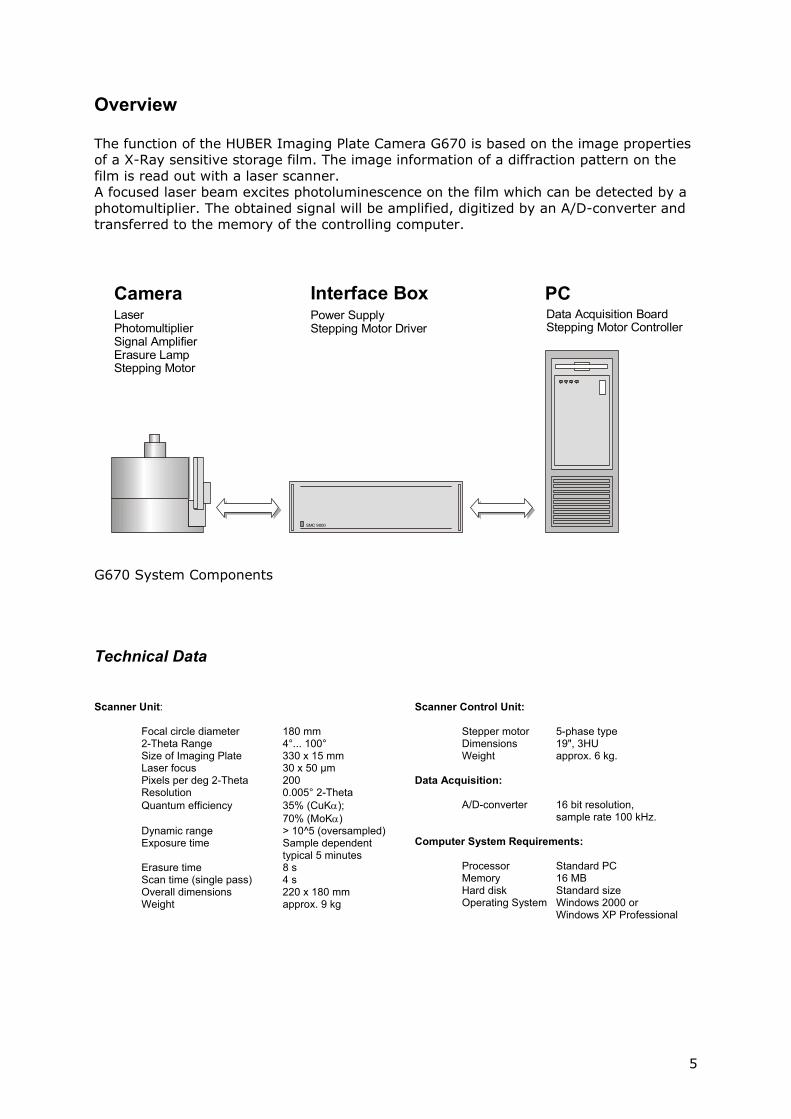
Overview The function of the HUBER Imaging Plate Camera G670 is based on the image properties of a X-Ray sensitive storage film. The image information of a diffraction pattern on the film is read out with a laser scanner. A focused laser beam excites photoluminescence on the film which can be detected by a photomultiplier. The obtained signal will be amplified, digitized by an A/D-converter and transferred to the memory of the controlling computer.
CameraLaserPhotomultiplierSignal AmplifierErasure LampStepping Motor
Power SupplyStepping Motor Driver
Data Acquisition BoardStepping Motor Controller
Interface Box PC
SMC 9000
G670 System Components
Technical Data Scanner Unit: Focal circle diameter 180 mm
2-Theta Range 4°... 100° Size of Imaging Plate 330 x 15 mm Laser focus 30 x 50 µm Pixels per deg 2-Theta 200 Resolution 0.005° 2-Theta Quantum efficiency 35% (CuKα); 70% (MoKα) Dynamic range > 10^5 (oversampled) Exposure time Sample dependent typical 5 minutes Erasure time 8 s Scan time (single pass) 4 s Overall dimensions 220 x 180 mm Weight approx. 9 kg
Scanner Control Unit: Stepper motor 5-phase type Dimensions 19", 3HU Weight approx. 6 kg. Data Acquisition:
A/D-converter 16 bit resolution, sample rate 100 kHz.
Computer System Requirements: Processor Standard PC Memory 16 MB Hard disk Standard size Operating System Windows 2000 or
Windows XP Professional
5
Installation The G670 camera requires the installation of two additional boards in your PC: A Keithley KPCI 3107 A/D-board which converts the analog PMT signal into digital data, and the Huber smc_pc.pci step motor controller board, which is responsible for the motion control of the IP scanning unit of the G670 camera.
PLEASE NOTE: For the installation of the software components you have to log on to your computer with an account that has administrative rights. Before you continue, you should terminate all running programs.
PLEASE NOTE: We recommend to deactivate all power saving features of your computer (BIOS settings) and the Windows operating system because they may cause some unpredictable results during data collection. We also recommend to deactivate any type of scheduled background tasks (screen savers, virus scanners, etc.).
STEP 1: Installation of the G670 data collection software The installation procedure of the G670 system starts with the installation of the G670 data collection software. Insert the G670 CD-ROM. If your Windows system is configured for auto-starting setup programs of inserted CD-ROMs, the G670 installation program will show up automatically. If it does not, start the Windows Explorer, change to the root directory of the CD-ROM drive and start SETUP.EXE manually. The G670 setup program will guide you through the installation process.
STEP 2: Installation of the A/D-converter board For the Keithley A/D-converter board, it is important to install the driver software prior to installing the board itself. Otherwise Windows may have problems recognizing the board. You have to use the original Keithley CD-ROM (Rev. 3108-850a04 or newer) which is delivered with the board. Just start the corresponding installation program SETUP.EXE, if it doesn’t start automatically after insertion of the CD-ROM. Click on button 'Next' on the DriverLinx Browser window and select button 'Install DriverLINX'. On the next window select button 'Install Drivers'. Then follow the instructions of the InstallShield Setup Wizard. After all driver files have been copied to your PC, select buttons 'Finish', 'Exit' and finally quit the installation program by a click on 'Done'. Shutdown your PC and install the board as described below.
6
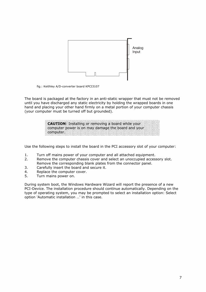
AnalogInput
fig.: Keithley A/D-converter board KPCI3107
The board is packaged at the factory in an anti-static wrapper that must not be removed until you have discharged any static electricity by holding the wrapped boards in one hand and placing your other hand firmly on a metal portion of your computer chassis (your computer must be turned off but grounded).
CAUTION: Installing or removing a board while your computer power is on may damage the board and your computer.
Use the following steps to install the board in the PCI accessory slot of your computer: 1. Turn off mains power of your computer and all attached equipment. 2. Remove the computer chassis cover and select an unoccupied accessory slot.
Remove the corresponding blank plates from the connector panel. 3. Carefully insert the board and secure it. 4. Replace the computer cover. 5. Turn mains power on. During system boot, the Windows Hardware Wizard will report the presence of a new PCI-Device. The installation procedure should continue automatically. Depending on the type of operating system, you may be prompted to select an installation option: Select option 'Automatic installation …' in this case.
7
STEP 3: Stepping Motor Controller Board Software Installation In contrast to the installation of the Keithley PCI-board, it is not necessary to install any software prior to installing the board. Dialogues may vary during the following procedure depending on the type of operating system you use. Install the smc_pc.pci board and the auxiliary I/O-port connector plate the same way you installed the Keithley A/D-board.
The Windowboard. The H For the type'Manual instdriver softwa When you arand change the operatin The Hardwaoperating sylist or contin Finally, you Microsoft. It
STEP 4: Ins Due to manuangle positioA floppy diskbe installed description 'installation dThe presencfile is found,
8
PLEASE NOTE: When your PC boots for the first time after insertion of the smc_pc.pci board, you should check the following BIOS setting (located in 'PCI-settings'):
Plug & Play OS: NO If it is set to ‘YES’, Windows may have problems to install the drivers, i.e. the smc_pc.pci-board may not be recognized properly.
s Hardware Wizard should start again after installation of the smc_pc.pci-ardware Wizard will report the presence of a new 'PCI-device'.
of installation, do not select the 'Automatic installation…' option. Select the allation…' option instead, which allows you to select a source folder for the re.
e prompted to enter the driver source folder, select the your CD-ROM drive to folder \smc_pc\driver. From there, select the folder that corresponds to g system you are currently using, for example 'winxp', and continue.
re Wizard will find drivers for a board named ‘smc_pc.pci’. Depending on your stem, the Hardware Wizard either prompts you to select this driver from a ues automatically. However, just follow the instructions.
may probably get a message which states that this driver is not certified by is really not certified, but you have to install this driver anyway.
tallation of the correction file
facturing tolerances, the scanning device of the camera generates a certain ning error during data readout. with a correction file is delivered with the camera. This correction file must in order to allow either manual or automatic data correction (see command Edit – Correct Data'). Insert the floppy disk and copy the file 'camera.cor' to the irectory of the G670 software you selected before. e of this file will be checked every time the program starts. If no correction the corresponding correction function is not available.
STEP 5: Camera Installation We assume that you have already installed and properly adjusted the basic equipment for using the Guinier Camera, i.e. the radiation source with the primary monochromator 611 and the adjustment base 601. The camera may be delivered with the erasure lamp packed separately. In this case, open the four screws of the light-bulb holder on top of the camera, remove the top part and insert the lamp.
CAUTION: Do not touch the lamp body directly with your fingers. This will shorten the lifetime of the halogen light-bulb. Cut off the bottom end of the little plastic bag and keep the bulb wrapped until it is properly plugged in.
Now you are ready to place the camera onto the adjustment base 601.
Cable Connections
CAUTION: Discharge static electricity prior to connecting any cables.
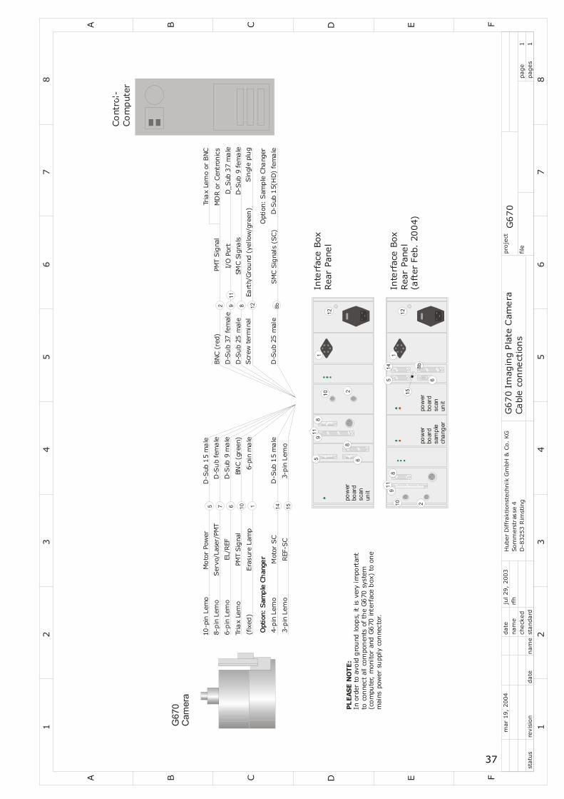
Make sure that computer and the interface box are both switched off. Simply establish all cable connections between computer, controller box and the camera. The cables cannot be mixed up, they all have different connectors or can be distinguished by color. There is one exception: Interface boxes delivered after January 2004 may be equipped with a pair of female 15-pin D-sub connectors. The drive motor of the Imaging Plate scan unit must be connected to the left connector The second one is used to connect the drive motor of the sample changer option (see figure 'Cable Connections…' in the appendix). ATTENTION: The Keithley KPCI 3107 A/D-board is equipped with two identical 36-pin MDR connectors. Please make sure you connect the signal cable to the upper (analog input) connector (see figure in chapter Installation).
PLEASE NOTE: You must connect the line voltage power supply cables of all components (i.e. computer, monitor and interface box) to the same mains power plug socket in order to have a common earth point. Otherwise you may observe low level signal ripple due to ground loop effects.
STEP 6: Final Preparations Please make sure to insert the soller slit between monochromator and Camera. You may get unpredictable diffraction patterns due to X-Rays scattered within the monochromator or at the surface of the sample holder.
9
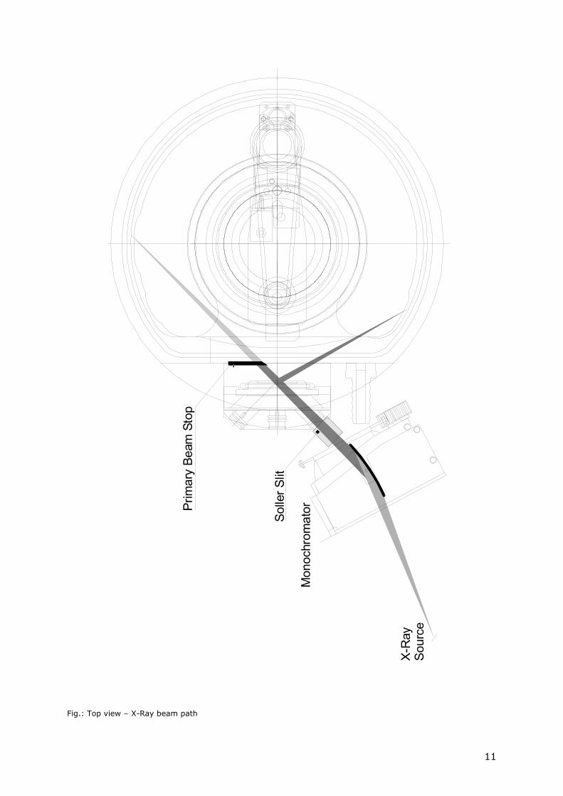
The same may happen, if the primary beam stop slide is not adjusted correctly. Move the tungsten slide to a position where it completely screens the primary beam as shown on the top view figure of the camera on the following page. The small fluorescent screen on the slide will make the primary beam visible and support the adjustment procedure.
ATTENTION: If you remove the sample holder, make sure that the mounting surface of sample holder and camera is free of dirt and dust. Otherwise you will receive erroneous measurement results.
10
CAUTION: Never expose parts of the Imaging Plate to the primary X-Ray beam. This may cause a permanent damage of the Imaging Plate.
X-R
aySo
urce
Mon
ochr
omat
or
Solle
r Slit
Prim
ary
Beam
Sto
p
Fig.: Top view – X-Ray beam path
11
Installation of Additional Hardware
Sample Changer
Connect twoCall the menbutton 'Optiothe correspo
High Temp Just establiscomputer usThe default edit G670.INyou use. Witand check thchecks the pmenu 'HTC' please refer
Laser High Just establisyour computcontroller. Tyou have to to the port nparameter. Within G670the button 'Opresence of 'Laser' if the the correspo
Low Tempe Just establisserial port owith the conCOM port, y
12
CAUTION: Please switch off the interface box before you establish any cable connection.
cables of the sample changer device to the rear of the G670 interface box. u command 'File – Settings' and select the 'Options'-tab and and check the ns – Sample Changer'. If this option is enabled, G670 checks the presence of nding hardware during program start and provides an additional menu 'SC'.
erature Controller HTC 9634
h the cable connection between the HTC 9634 and a free serial port of your ing the interface cable that should have been delivered with the controller. serial interface is COM1. If you want to use a different COM port, you have to I. In section [HTC], change setting SerialPort= according to the port number hin G670, call the menu command 'File – Settings', select the 'Options'-tab and e button 'Options – High Temperature (HTC)'. If this option is enabled, G670 resence of the controller during program start and provides an additional if the controller was found. For details about the temperature controller, to the instruction manual of the HTC 9634.
Temperature Controller
h the cable connection between the Laser controller and a free serial port of er using the interface cable that should have been delivered with the he default serial interface is COM1. If you want to use a different COM port, edit G670.INI. In section [HTC_Laser], change setting SerialPort= according umber you use. If not yet present, add this section and the corresponding
, call the menu command 'File – Settings', select the 'Options'-tab and check ptions – High Temperature (Laser)'. If this option is enabled, G670 checks the
the laser controller during program start and provides an additional menu controller was found. For details about the laser controller, please refer to nding instruction manual.
rature Controller Lake Shore 330
h the cable connection between the Lake Shore 330 controller and a free f your computer using the interface cable that should have been delivered troller. The default serial interface is COM1. If you want to use a different ou have to edit G670.INI. In section [LTC], change setting SerialPort=
according to the port number you use. Within G670, call the menu command 'File – Settings' and check the button 'Options – Low Temperature'. If this option is enabled, G670 checks the presence of the controller during program start and provides an additional menu 'LTC' if the controller was found. Please refer to the instruction manual of the Lake Shore 330 controller for details.
Low Temperature Controller Lake Shore DRC91-C Usage of this controller requires the presence of a working IEEE (GPIB) interface board in your computer. Hewlett Packard or National Instruments boards are supported so far. By default, G670 assumes the presence of a HP board (usually a HP82350 PCI-board) configured for a SICL interface name hpib7. In any case, you have to edit G670.INI in order to configure G670 for communication across this interface. In section [LTC] of G670.INI, add the following two lines: LTCModel=DRC91 and GPIBDeviceAddress=24. If you use a National Instruments board, you have to add the line GPIBType=Nat. After starting G670, call the menu command 'File – Settings' and check the button 'Options – Low Temperature'. If this option is enabled, G670 checks the presence of the controller during program start and provides an additional menu 'LTC' if the controller was found. Please refer to the instruction manual of the Lake Shore DRC91-C controller for details.
13
Using the Software
Preface The primary function of the Guinier G670 Data Acquisition Program is, to read out the diffraction pattern generated on the Imaging Plate during X-Ray exposure. The program enables you to save the sampled data in several file formats for further treatment.
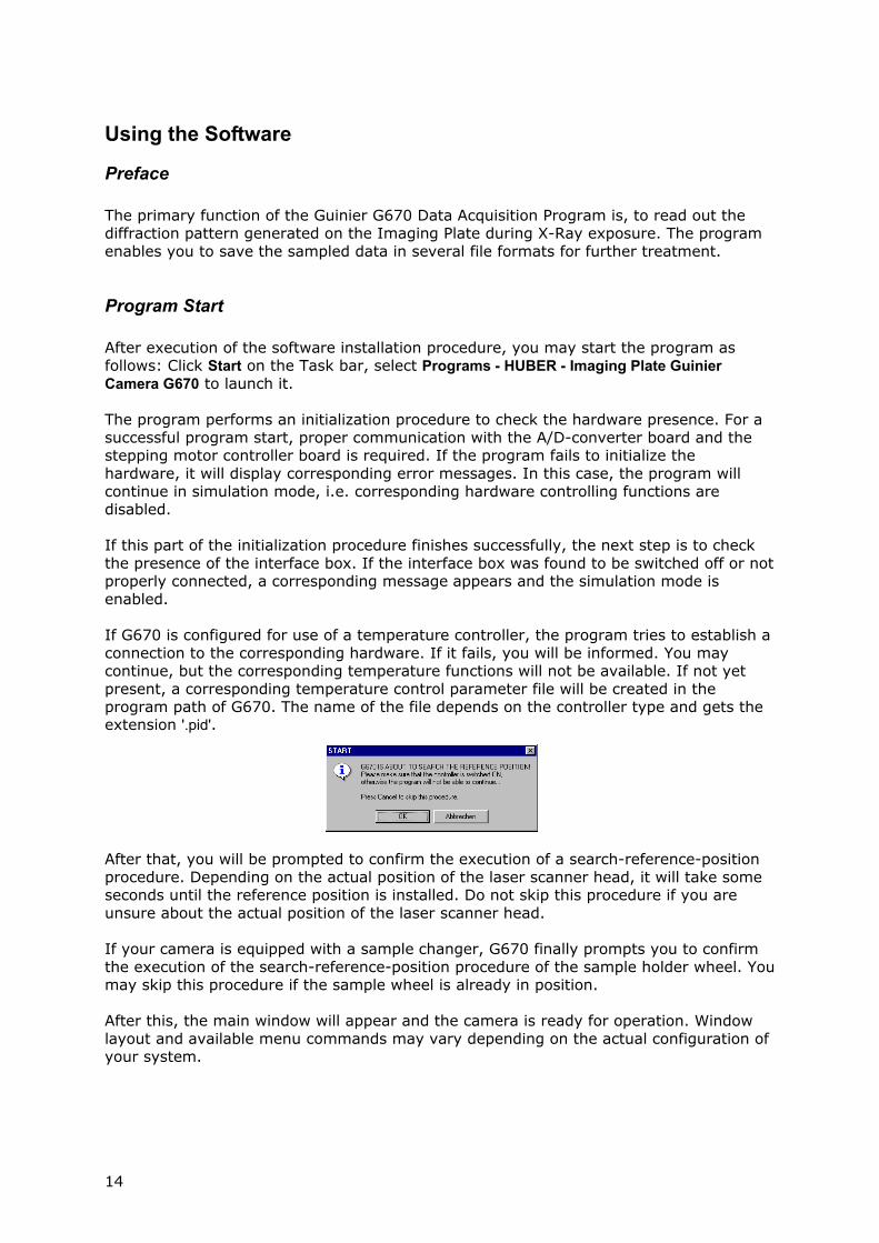
Program Start After execution of the software installation procedure, you may start the program as follows: Click Start on the Task bar, select Programs - HUBER - Imaging Plate Guinier Camera G670 to launch it. The program performs an initialization procedure to check the hardware presence. For a successful program start, proper communication with the A/D-converter board and the stepping motor controller board is required. If the program fails to initialize the hardware, it will display corresponding error messages. In this case, the program will continue in simulation mode, i.e. corresponding hardware controlling functions are disabled. If this part of the initialization procedure finishes successfully, the next step is to check the presence of the interface box. If the interface box was found to be switched off or not properly connected, a corresponding message appears and the simulation mode is enabled. If G670 is configured for use of a temperature controller, the program tries to establish a connection to the corresponding hardware. If it fails, you will be informed. You may continue, but the corresponding temperature functions will not be available. If not yet present, a corresponding temperature control parameter file will be created in the program path of G670. The name of the file depends on the controller type and gets the extension '.pid'.
After that, you will be prompted to confirm the execution of a search-reference-position procedure. Depending on the actual position of the laser scanner head, it will take some seconds until the reference position is installed. Do not skip this procedure if you are unsure about the actual position of the laser scanner head. If your camera is equipped with a sample changer, G670 finally prompts you to confirm the execution of the search-reference-position procedure of the sample holder wheel. You may skip this procedure if the sample wheel is already in position. After this, the main window will appear and the camera is ready for operation. Window layout and available menu commands may vary depending on the actual configuration of your system.
14
The First Measurement We assume that your camera is properly mounted and adjusted with respect to the X-Ray beam. Please make sure that the soller slit is inserted and the primary beam stop slide is adjusted to completely screen the primary beam (see chapter 'Camera Installation'). For an initial test, you should use a well known reference sample such as Silicon or Quartz. Just insert the sample, switch on the sample movement, open the X-Ray shutter and select the menu command 'Measurement -Start Exposure'. The default exposure time is one minute, which should be sufficient to get an overview about the behaviour of the sample. The 'Date'-field will be updated automatically after readout of the Imaging Plate and you may edit the remaining input fields later on prior to saving the data on your hard disk.
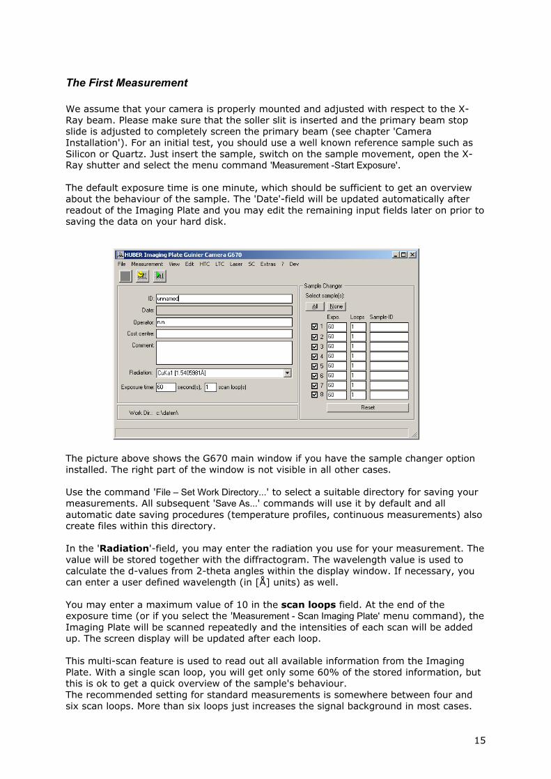
The picture above shows the G670 main window if you have the sample changer option installed. The right part of the window is not visible in all other cases. Use the command 'File – Set Work Directory...' to select a suitable directory for saving your measurements. All subsequent 'Save As...' commands will use it by default and all automatic date saving procedures (temperature profiles, continuous measurements) also create files within this directory. In the 'Radiation'-field, you may enter the radiation you use for your measurement. The value will be stored together with the diffractogram. The wavelength value is used to calculate the d-values from 2-theta angles within the display window. If necessary, you can enter a user defined wavelength (in [Å] units) as well. You may enter a maximum value of 10 in the scan loops field. At the end of the exposure time (or if you select the 'Measurement - Scan Imaging Plate' menu command), the Imaging Plate will be scanned repeatedly and the intensities of each scan will be added up. The screen display will be updated after each loop. This multi-scan feature is used to read out all available information from the Imaging Plate. With a single scan loop, you will get only some 60% of the stored information, but this is ok to get a quick overview of the sample's behaviour. The recommended setting for standard measurements is somewhere between four and six scan loops. More than six loops just increases the signal background in most cases.
15
If you are using the sample changer device, you may set individual values for exposure time, scan loops and ID of each sample. If you want to skip sample positions, just deactivate the corresponding check box on the left side of the sample number.
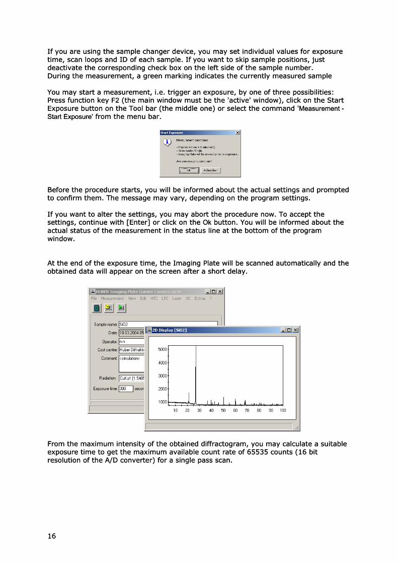
If you are using the sample changer device, you may set individual values for exposure time, scan loops and ID of each sample. If you want to skip sample positions, just deactivate the corresponding check box on the left side of the sample number. During the measurement, a green marking indicates the currently measured sample During the measurement, a green marking indicates the currently measured sample You may start a measurement, i.e. trigger an exposure, by one of three possibilities: Press function key F2 (the main window must be the 'active' window), click on the Start Exposure button on the Tool bar (the middle one) or select the command 'Measurement - Start Exposure' from the menu bar.
You may start a measurement, i.e. trigger an exposure, by one of three possibilities: Press function key F2 (the main window must be the 'active' window), click on the Start Exposure button on the Tool bar (the middle one) or select the command 'Measurement - Start Exposure' from the menu bar.
Before the procedure starts, you will be informed about the actual settings and prompted to confirm them. The message may vary, depending on the program settings. Before the procedure starts, you will be informed about the actual settings and prompted to confirm them. The message may vary, depending on the program settings. If you want to alter the settings, you may abort the procedure now. To accept the settings, continue with [Enter] or click on the Ok button. You will be informed about the actual status of the measurement in the status line at the bottom of the program window.
If you want to alter the settings, you may abort the procedure now. To accept the settings, continue with [Enter] or click on the Ok button. You will be informed about the actual status of the measurement in the status line at the bottom of the program window. At the end of the exposure time, the Imaging Plate will be scanned automatically and the obtained data will appear on the screen after a short delay. At the end of the exposure time, the Imaging Plate will be scanned automatically and the obtained data will appear on the screen after a short delay.
From the maximum intensity of the obtained diffractogram, you may calculate a suitable exposure time to get the maximum available count rate of 65535 counts (16 bit resolution of the A/D converter) for a single pass scan.
From the maximum intensity of the obtained diffractogram, you may calculate a suitable exposure time to get the maximum available count rate of 65535 counts (16 bit resolution of the A/D converter) for a single pass scan.
16 16
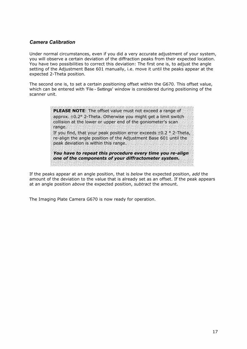
Camera Calibration Under normal circumstances, even if you did a very accurate adjustment of your system, you will observe a certain deviation of the diffraction peaks from their expected location. You have two possibilities to correct this deviation: The first one is, to adjust the angle setting of the Adjustment Base 601 manually, i.e. move it until the peaks appear at the expected 2-Theta position. The second one is, to set a certain positioning offset within the G670. This offset value, which can be entered with 'File - Settings' window is considered during positioning of the scanner unit.
PLEASE NOTE: The offset value must not exceed a range of approx. ±0.2° 2-Theta. Otherwise you might get a limit switch collision at the lower or upper end of the goniometer's scan range. If you find, that your peak position error exceeds ±0.2 ° 2-Theta, re-align the angle position of the Adjustment Base 601 until the peak deviation is within this range. You have to repeat this procedure every time you re-align one of the components of your diffractometer system.
If the peaks appear at an angle position, that is below the expected position, add the amount of the deviation to the value that is already set as an offset. If the peak appears at an angle position above the expected position, subtract the amount. The Imaging Plate Camera G670 is now ready for operation.
17
The Menu Bar The following paragraphs describe the complete function set of the program ordered by their occurrence in the menu bar. Depending on the installed an configured options, the appearance of the main window and the available commands may vary.
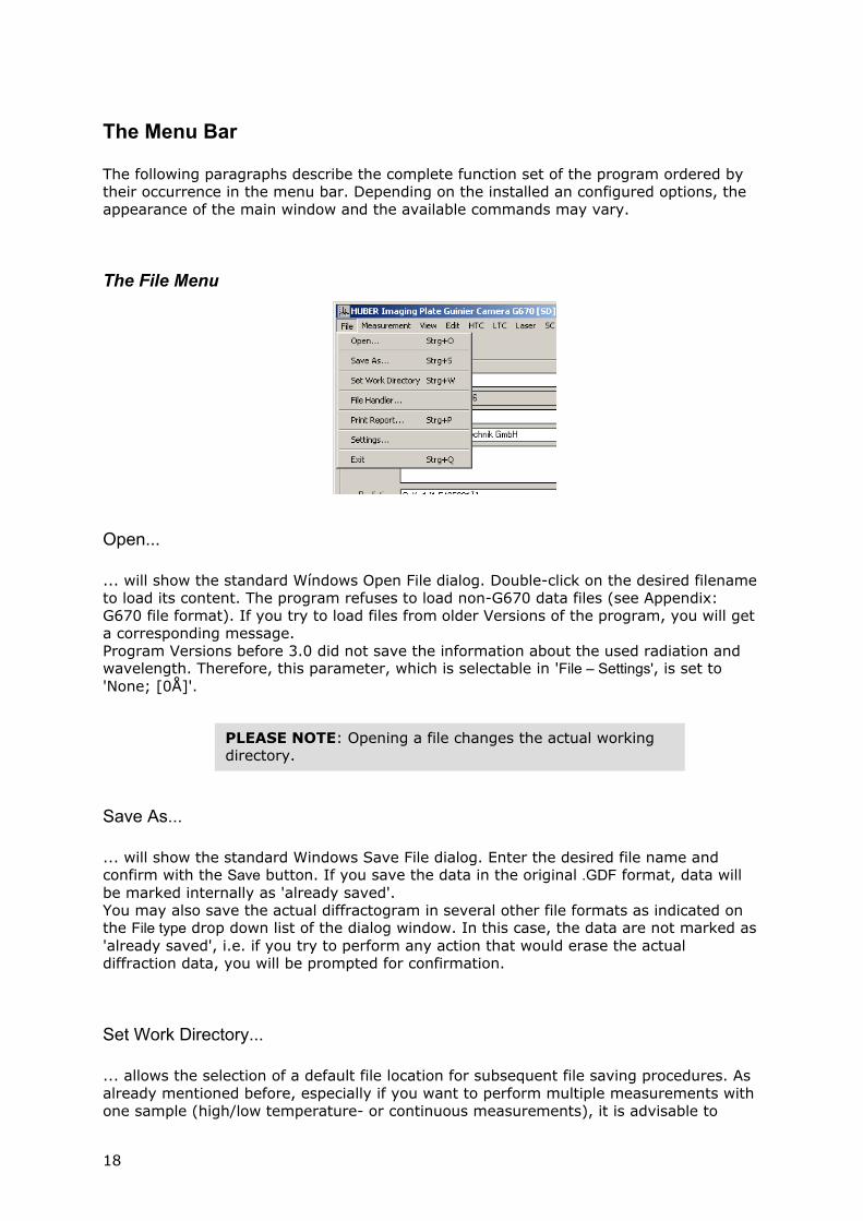
The File Menu
Open... ... will show the standard Wíndows Open File dialog. Double-click on the desired filename to load its content. The program refuses to load non-G670 data files (see Appendix: G670 file format). If you try to load files from older Versions of the program, you will get a corresponding message. Program Versions before 3.0 did not save the information about the used radiation and wavelength. Therefore, this parameter, which is selectable in 'File – Settings', is set to 'None; [0Å]'.
PLEASE NOTE: Opening a file changes the actual working directory.
Save As... ... will show the standard Windows Save File dialog. Enter the desired file name and confirm with the Save button. If you save the data in the original .GDF format, data will be marked internally as 'already saved'. You may also save the actual diffractogram in several other file formats as indicated on the File type drop down list of the dialog window. In this case, the data are not marked as 'already saved', i.e. if you try to perform any action that would erase the actual diffraction data, you will be prompted for confirmation.
Set Work Directory... ... allows the selection of a default file location for subsequent file saving procedures. As already mentioned before, especially if you want to perform multiple measurements with one sample (high/low temperature- or continuous measurements), it is advisable to
18
select a work directory prior to starting a measurement in order to avoid a file mess. The directory must already exist, i.e. you have to use the Windows Explorer for creation.
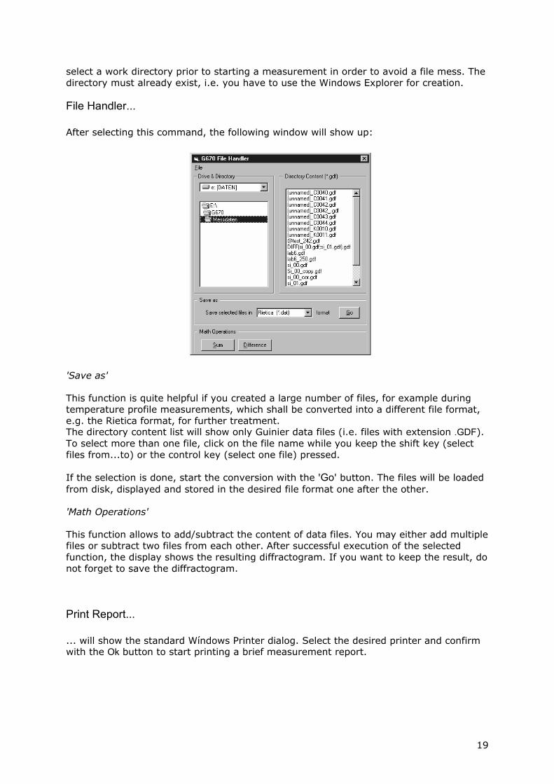
File Handler... After selecting this command, the following window will show up:
'Save as' This function is quite helpful if you created a large number of files, for example during temperature profile measurements, which shall be converted into a different file format, e.g. the Rietica format, for further treatment. The directory content list will show only Guinier data files (i.e. files with extension .GDF). To select more than one file, click on the file name while you keep the shift key (select files from...to) or the control key (select one file) pressed. If the selection is done, start the conversion with the 'Go' button. The files will be loaded from disk, displayed and stored in the desired file format one after the other. 'Math Operations' This function allows to add/subtract the content of data files. You may either add multiple files or subtract two files from each other. After successful execution of the selected function, the display shows the resulting diffractogram. If you want to keep the result, do not forget to save the diffractogram.
Print Report... ... will show the standard Wíndows Printer dialog. Select the desired printer and confirm with the Ok button to start printing a brief measurement report.
19
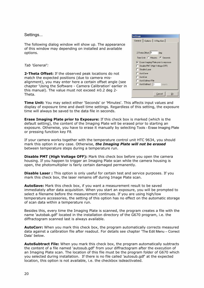
Settings...
The following dialog window will show up. The appearance of this window may depending on installed and available options. Tab 'General': 2-Theta Offset: If the observed peak locations do not match the expected positions (due to camera mis-alignment), you may enter here a certain offset angle (see chapter 'Using the Software - Camera Calibration' earlier in this manual). The value must not exceed ±0.2 deg 2-Theta. Time Unit: You may select either 'Seconds' or 'Minutes'. This affects input values and display of exposure time and dwell time settings. Regardless of this setting, the exposure time will always be saved to the data file in seconds. Erase Imaging Plate prior to Exposure: If this check box is marked (which is the default setting), the content of the Imaging Plate will be erased prior to starting an exposure. Otherwise, you have to erase it manually by selecting Tools - Erase Imaging Plate or pressing function key F8. If your camera works together with the temperature control unit HTC 9634, you should mark this option in any case. Otherwise, the Imaging Plate will not be erased between temperature steps during a temperature run. Disable PMT (High Voltage OFF): Mark this check box before you open the camera housing. If you happen to trigger an Imaging Plate scan while the camera housing is open, the photomultiplier is fairly certain damaged permanently. Disable Laser : This option is only useful for certain test and service purposes. If you mark this check box, the laser remains off during Image Plate scan. AutoSave: Mark this check box, if you want a measurement result to be saved immediately after data acquisition. When you start an exposure, you will be prompted to select a filename before the measurement continues. If you are using high/low temperature accessories, the setting of this option has no effect on the automatic storage of scan data within a temperature run. Besides this, every time the Imaging Plate is scanned, the program creates a file with the name 'autobak.gdf' located in the installation directory of the G670 program, i.e. the diffractogram scanned last is always available. AutoCorr: When you mark this check box, the program automatically corrects measured data against a calibration file after readout. For details see chapter 'The Edit Menu – Correct Data' below. AutoSubtract File: When you mark this check box, the program automatically subtracts the content of a file named 'autosub.gdf' from your diffractogram after the execution of an Imaging Plate scan. The location of this file must be the program folder of G670 which you selected during installation. If there is no file called 'autosub.gdf' at the expected location, this option is not available, i.e. the checkbox isdeactivated.
20
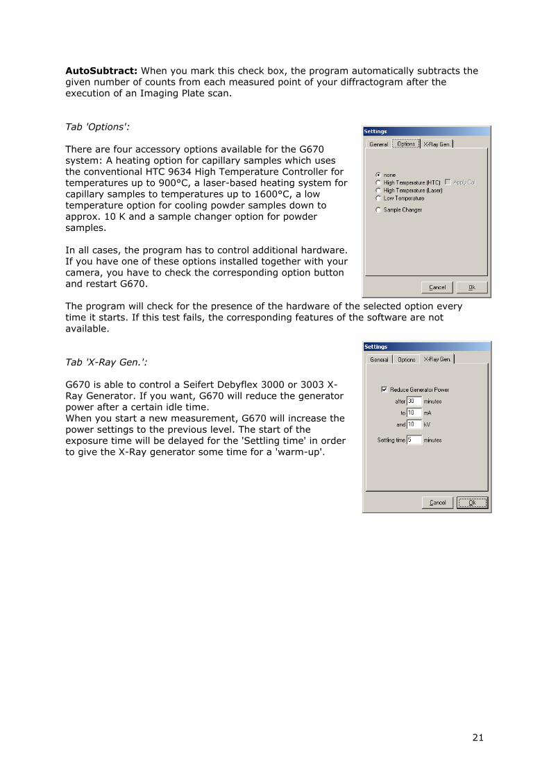
AutoSubtract: When you mark this check box, the program automatically subtracts the given number of counts from each measured point of your diffractogram after the execution of an Imaging Plate scan. Tab 'Options': There are four accessory options available for the G670 system: A heating option for capillary samples which uses the conventional HTC 9634 High Temperature Controller for temperatures up to 900°C, a laser-based heating system for capillary samples to temperatures up to 1600°C, a low temperature option for cooling powder samples down to approx. 10 K and a sample changer option for powder samples. In all cases, the program has to control additional hardware. If you have one of these options installed together with your camera, you have to check the corresponding option button and restart G670. The program will check for the presence of the hardware of the selected option every time it starts. If this test fails, the corresponding features of the software are not available. Tab 'X-Ray Gen.': G670 is able to control a Seifert Debyflex 3000 or 3003 X-Ray Generator. If you want, G670 will reduce the generator power after a certain idle time. When you start a new measurement, G670 will increase the power settings to the previous level. The start of the exposure time will be delayed for the 'Settling time' in order to give the X-Ray generator some time for a 'warm-up'.
21
Exit ...will terminate program execution. If the actual data in memory were not yet saved, you will be prompted to either confirm or cancel your selection.
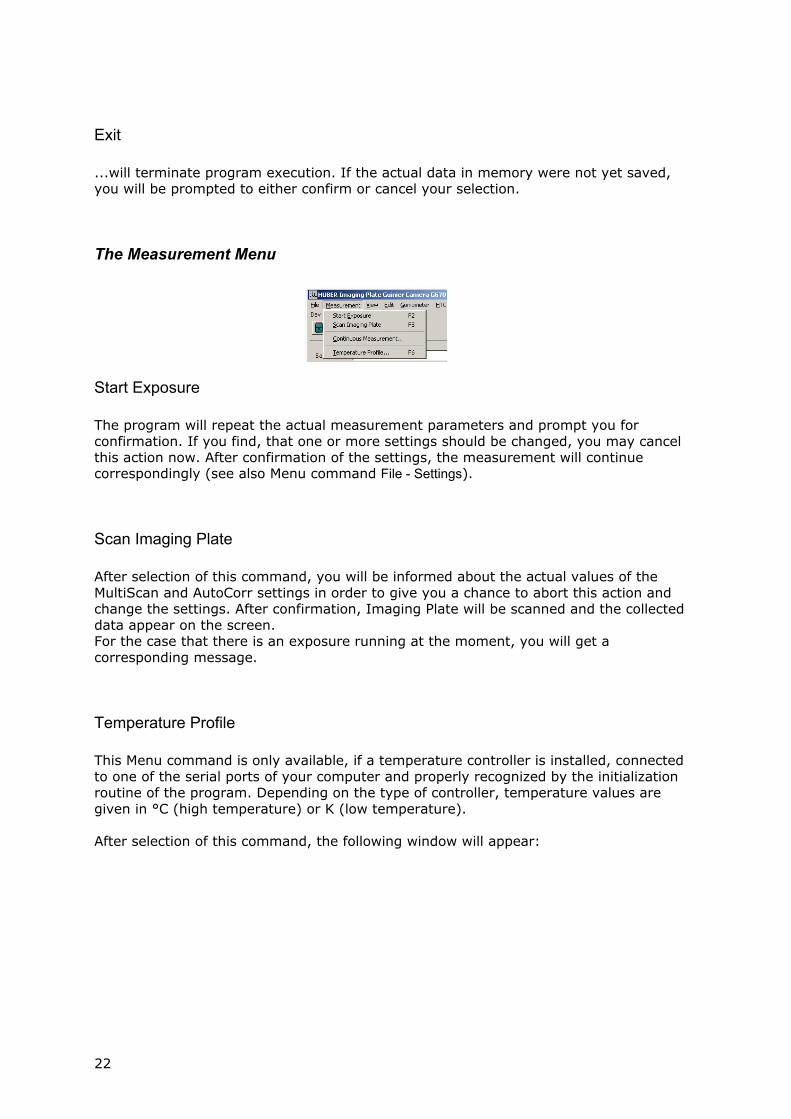
The Measurement Menu
Start Exposure The program will repeat the actual measurement parameters and prompt you for confirmation. If you find, that one or more settings should be changed, you may cancel this action now. After confirmation of the settings, the measurement will continue correspondingly (see also Menu command File - Settings).
Scan Imaging Plate After selection of this command, you will be informed about the actual values of the MultiScan and AutoCorr settings in order to give you a chance to abort this action and change the settings. After confirmation, Imaging Plate will be scanned and the collected data appear on the screen. For the case that there is an exposure running at the moment, you will get a corresponding message.
Temperature Profile This Menu command is only available, if a temperature controller is installed, connected to one of the serial ports of your computer and properly recognized by the initialization routine of the program. Depending on the type of controller, temperature values are given in °C (high temperature) or K (low temperature). After selection of this command, the following window will appear:
22
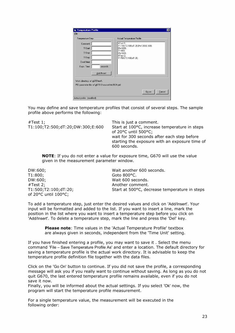
You may define and save temperature profiles that consist of several steps. The sample profile above performs the following: #Test 1; This is just a comment. T1:100;T2:500;dT:20;DW:300;E:600 Start at 100°C, increase temperature in steps
of 20°C until 500°C; wait for 300 seconds after each step before starting the exposure with an exposure time of 600 seconds.
NOTE: If you do not enter a value for exposure time, G670 will use the value given in the measurement parameter window.
DW:600; Wait another 600 seconds. T1:800; Goto 800°C. DW:600; Wait 600 seconds. #Test 2; Another comment. T1:500;T2:100;dT:20; Start at 500°C, decrease temperature in steps of 20°C until 100°C; To add a temperature step, just enter the desired values and click on 'Add/Insert'. Your input will be formatted and added to the list. If you want to insert a line, mark the position in the list where you want to insert a temperature step before you click on 'Add/Insert'. To delete a temperature step, mark the line and press the 'Del' key.
Please note: Time values in the 'Actual Temperature Profile' textbox are always given in seconds, independent from the 'Time Unit' setting.
If you have finished entering a profile, you may want to save it . Select the menu command 'File – Save Temperature Profile As' and enter a location. The default directory for saving a temperature profile is the actual work directory. It is advisable to keep the temperature profile definition file together with the data files. Click on the 'Go On' button to continue. If you did not save the profile, a corresponding message will ask you if you really want to continue without saving. As long as you do not quit G670, the last entered temperature profile remains available, even if you do not save it now. Finally, you will be informed about the actual settings. If you select 'Ok' now, the program will start the temperature profile measurement. For a single temperature value, the measurement will be executed in the following order:
23

- transfer temperature setting and control parameter to the
temperature controller. - wait until desired temperature is reached - stay there for given dwell time (if any) - erase Imaging Plate (depends on option 'Erase Imaging Plate prior
to exposure' within 'File - Settings' - start exposure time - scan Imaging Plate - save scan data in actual work directory (independent from setting
'AutoSave' in 'File - Settings' This sequence will be repeated for each temperature step in the profile
24
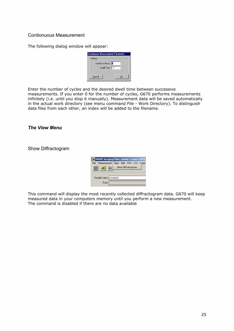
Contionuous Measurement The following dialog window will appear:
Enter the number of cycles and the desired dwell time between successive measurements. If you enter 0 for the number of cycles, G670 performs measurements infinitely (i.e. until you stop it manually). Measurement data will be saved automatically in the actual work directory (see menu command File - Work Directory). To distinguish data files from each other, an index will be added to the filename.
The View Menu
Show Diffractogram
This command will display the most recently collected diffractogram data. G670 will keep measured data in your computers memory until you perform a new measurement. The command is disabled if there are no data available
25
The Edit Menu
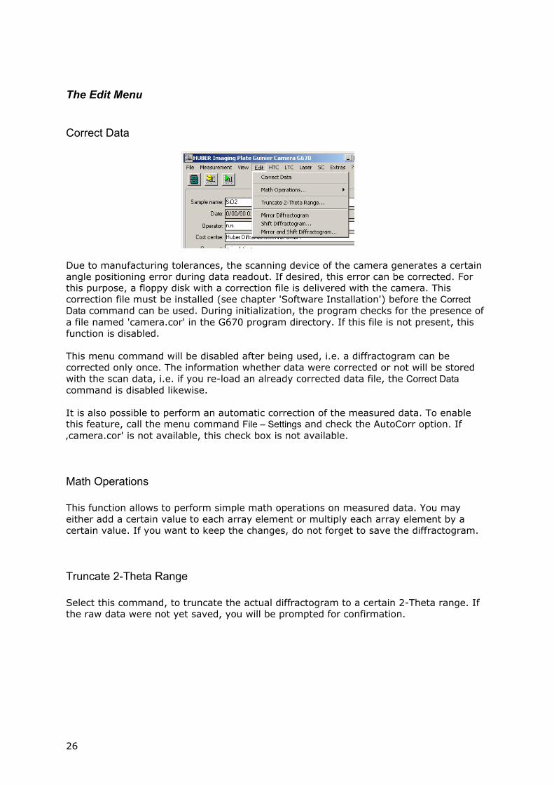
Correct Data
Due to manufacturing tolerances, the scanning device of the camera generates a certain angle positioning error during data readout. If desired, this error can be corrected. For this purpose, a floppy disk with a correction file is delivered with the camera. This correction file must be installed (see chapter 'Software Installation') before the Correct Data command can be used. During initialization, the program checks for the presence of a file named 'camera.cor' in the G670 program directory. If this file is not present, this function is disabled. This menu command will be disabled after being used, i.e. a diffractogram can be corrected only once. The information whether data were corrected or not will be stored with the scan data, i.e. if you re-load an already corrected data file, the Correct Data command is disabled likewise. It is also possible to perform an automatic correction of the measured data. To enable this feature, call the menu command File – Settings and check the AutoCorr option. If ‚camera.cor' is not available, this check box is not available.
Math Operations This function allows to perform simple math operations on measured data. You may either add a certain value to each array element or multiply each array element by a certain value. If you want to keep the changes, do not forget to save the diffractogram.
Truncate 2-Theta Range Select this command, to truncate the actual diffractogram to a certain 2-Theta range. If the raw data were not yet saved, you will be prompted for confirmation.
26
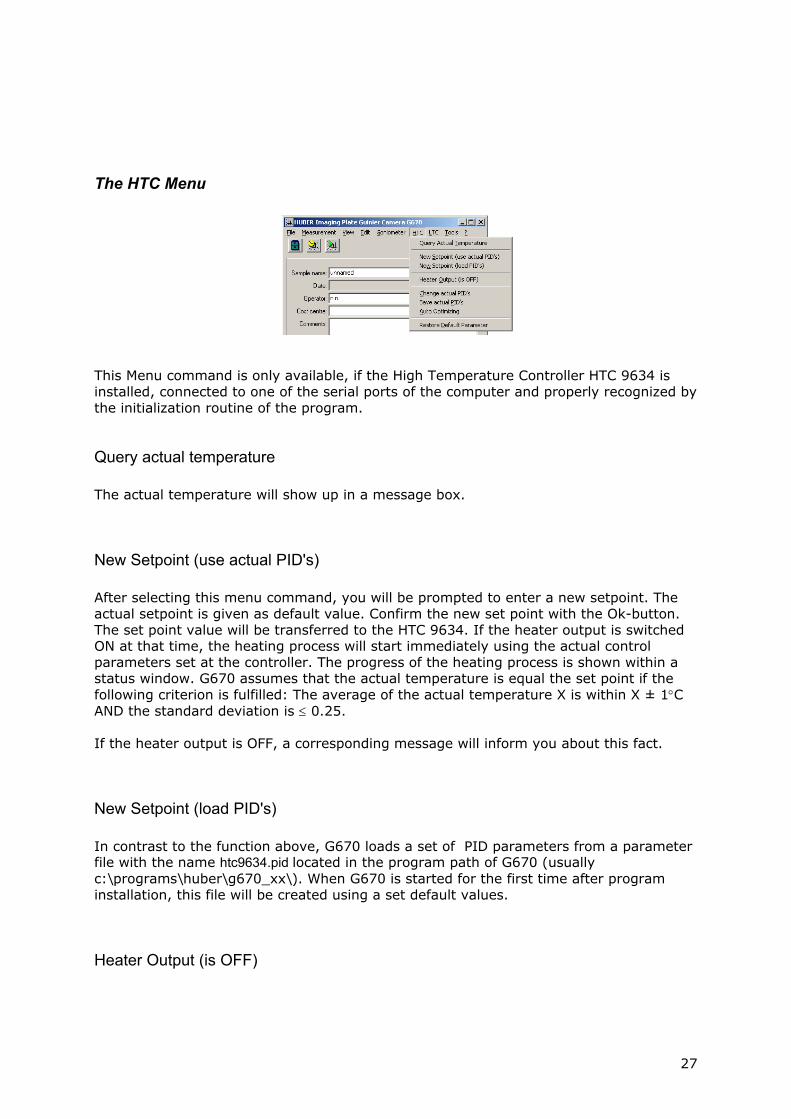
The HTC Menu
This Menu command is only available, if the High Temperature Controller HTC 9634 is installed, connected to one of the serial ports of the computer and properly recognized by the initialization routine of the program.
Query actual temperature The actual temperature will show up in a message box.
New Setpoint (use actual PID's) After selecting this menu command, you will be prompted to enter a new setpoint. The actual setpoint is given as default value. Confirm the new set point with the Ok-button. The set point value will be transferred to the HTC 9634. If the heater output is switched ON at that time, the heating process will start immediately using the actual control parameters set at the controller. The progress of the heating process is shown within a status window. G670 assumes that the actual temperature is equal the set point if the following criterion is fulfilled: The average of the actual temperature X is within X ± 1°C AND the standard deviation is ≤ 0.25. If the heater output is OFF, a corresponding message will inform you about this fact.
New Setpoint (load PID's) In contrast to the function above, G670 loads a set of PID parameters from a parameter file with the name htc9634.pid located in the program path of G670 (usually c:\programs\huber\g670_xx\). When G670 is started for the first time after program installation, this file will be created using a set default values.
Heater Output (is OFF)
27
PLEASE NOTE: There is a small switch on the rear panel of the HTC 9634 labeled with ON/OFF. This switch overrides the heater output setting and represents a second possibility to interrupt a heating process (in case of emergency or for testing reasons). If the controller does not start heating after switching the heater output to on, you should check the position this switch.
Depending on the actual state of the heater output, you can switch it OFF or ON. The actual state is shown in brackets.
Change actual PID's You can change PID-parameters for an actual setpoint manually with this command. G670 will query the actual control parameter set and show it as default values in the input mask.
PLEASE NOTE: The controller immediately continues a running heating process with the new parameter set. It could be a good idea to be prepared to switch off the heater power with the little switch mentioned above.
Save actual PID's The program will query the actual control parameter set from the controller and save them for the actual temperature setpoint to a file with the name htc9634.pid which is located in the program directory of G670 (usually c:\programs\huber\g670_xx\). When G670 is started for the first time after program installation, this file will created using a set default values. If you want, you can manipulate this file with any suitable ASCII-editor, e.g. Windows Notepad, and insert parameter values manually. The parameter syntax is
<temperature>=P<P-value>I<I-value>D<D-value> (one set per temperature and line, no blanks, all three values must be given. Example: 300=P100I20D4 for details concerning the parameter range, see HTC 9634 instruction manual)
Auto Optimizing The controller is capable of self-optimizing the PID-parameters for a certain set point. With one restriction: The actual temperature X at the beginning of the optimization is 20% of the total measuring range (usually 900°C) below the actual set point W. This means that you can not trigger the self-optimizing procedure for temperatures below 200°C if you have an actual temperature of 20°C. After successful termination of the self optimizing process, the determined control parameters are active. If you want to keep them for further use, you must save them with the 'Save actual PID's' menu command mentioned above.
28
Send Default Parameter Set In case of problems, you can transfer a default parameter set to the controller. The heater output will be switched off and the set point is set to 32°C. Keep in mind that the controller will accept transferred data only on condition that the control loop number is set to 1 (see HTC 9634 instruction manual).
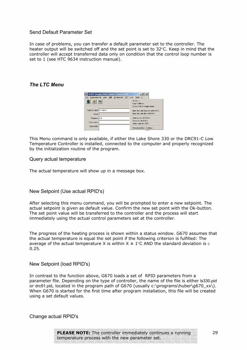
The LTC Menu
This Menu command is only available, if either the Lake Shore 330 or the DRC91-C Low Temperature Controller is installed, connected to the computer and properly recognized by the initialization routine of the program.
Query actual temperature The actual temperature will show up in a message box.
New Setpoint (Use actual RPID's) After selecting this menu command, you will be prompted to enter a new setpoint. The actual setpoint is given as default value. Confirm the new set point with the Ok-button. The set point value will be transferred to the controller and the process will start immediately using the actual control parameters set at the controller. The progress of the heating process is shown within a status window. G670 assumes that the actual temperature is equal the set point if the following criterion is fulfilled: The average of the actual temperature X is within X ± 1°C AND the standard deviation is ≤ 0.25.
New Setpoint (load RPID's) In contrast to the function above, G670 loads a set of RPID parameters from a parameter file. Depending on the type of controller, the name of the file is either ls330.pid or drc91.pid, located in the program path of G670 (usually c:\programs\huber\g670_xx\). When G670 is started for the first time after program installation, this file will be created using a set default values.
Change actual RPID's
29PLEASE NOTE: The controller immediately continues a running temperature process with the new parameter set.
You can change RPID-parameters for an actual setpoint manually with this command. G670 will query the actual control parameter set and show it as default values in the input mask.
Save actual RPID's The program will query the actual control parameter set from the controller and save them for the actual temperature setpoint in the corresponding parameter file (depending on the type of controller, either ls330.pid or drc91.pid) located in the program path of G670 (usually c:\programs\huber\g670_xx\). If you want, you can manipulate this file with any suitable ASCII-editor, e.g. Windows Notepad, and insert parameter values manually. The parameter syntax is
<temperature>=R<Range>P<P-value>I<I-value>D<D-value> (one set per temperature and line, no blanks, all four values must be given. Example: 300=R3P100I20D4 for details concerning the parameter range, please have a look at the corresponding Lake Shore instruction manual)
Autotuning The Lake Shore 330 controller is capable of auto-tuning the (R)PID-parameters for a certain set point. Please have a look at the corresponding Lake Shore instruction manual for details. This command is not available for the DRC 91 controller.
Restore Default Settings Selecting this command returns the controller settings to a default state.
The Laser Menu This Menu command is only available, if the laser heater system is installed, connected to the computer and properly recognized by the initialization routine of the program.
Switch Beam ON/OFF This will switch on the laser beam on or off, depending on the actual state. A corresponding command will be transferred to the controller.
New Temperature Setpoint The actual temperature will show up in a message box. You may enter a new temperature setpoint. Depending on the setting of the option '[A] temperature setpoint
30
values' within 'Settings' (see menu command File-Settings and select tab 'Laser'), you may define setpoint values indirect by entering the laser diode current in Ampere [A] units instead of entering a temperature in degree Celsius [°C].
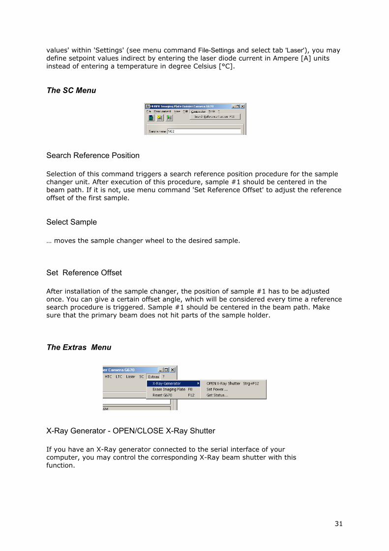
The SC Menu
Search Reference Position Selection of this command triggers a search reference position procedure for the sample changer unit. After execution of this procedure, sample #1 should be centered in the beam path. If it is not, use menu command 'Set Reference Offset' to adjust the reference offset of the first sample.
Select Sample … moves the sample changer wheel to the desired sample.
Set Reference Offset After installation of the sample changer, the position of sample #1 has to be adjusted once. You can give a certain offset angle, which will be considered every time a reference search procedure is triggered. Sample #1 should be centered in the beam path. Make sure that the primary beam does not hit parts of the sample holder.
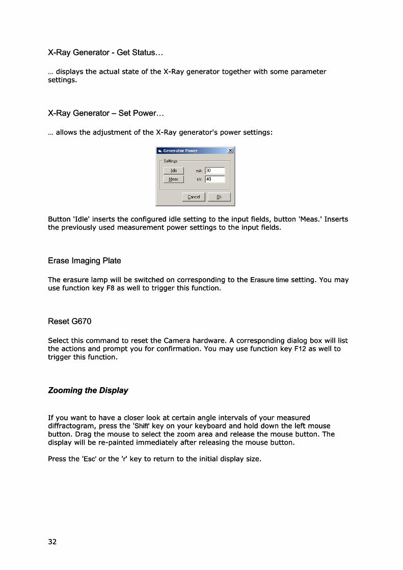
The Extras Menu
X-Ray Generator - OPEN/CLOSE X-Ray Shutter If you have an X-Ray generator connected to the serial interface of your computer, you may control the corresponding X-Ray beam shutter with this function.
31
X-Ray Generator - Get Status… X-Ray Generator - Get Status… … displays the actual state of the X-Ray generator together with some parameter settings. … displays the actual state of the X-Ray generator together with some parameter settings.
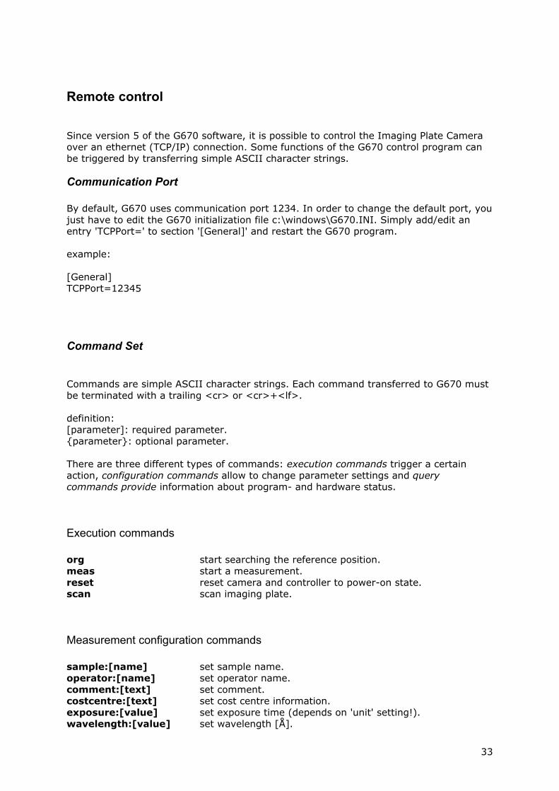
X-Ray Generator – Set Power… X-Ray Generator – Set Power… … allows the adjustment of the X-Ray generator's power settings: … allows the adjustment of the X-Ray generator's power settings:
Button 'Idle' inserts the configured idle setting to the input fields, button 'Meas.' Inserts the previously used measurement power settings to the input fields. Button 'Idle' inserts the configured idle setting to the input fields, button 'Meas.' Inserts the previously used measurement power settings to the input fields.
Erase Imaging Plate Erase Imaging Plate The erasure lamp will be switched on corresponding to the Erasure time setting. You may use function key F8 as well to trigger this function. The erasure lamp will be switched on corresponding to the Erasure time setting. You may use function key F8 as well to trigger this function.
Reset G670 Reset G670 Select this command to reset the Camera hardware. A corresponding dialog box will list the actions and prompt you for confirmation. You may use function key F12 as well to trigger this function.
Select this command to reset the Camera hardware. A corresponding dialog box will list the actions and prompt you for confirmation. You may use function key F12 as well to trigger this function.
Zooming the Display Zooming the Display If you want to have a closer look at certain angle intervals of your measured diffractogram, press the 'Shift' key on your keyboard and hold down the left mouse button. Drag the mouse to select the zoom area and release the mouse button. The display will be re-painted immediately after releasing the mouse button.
If you want to have a closer look at certain angle intervals of your measured diffractogram, press the 'Shift' key on your keyboard and hold down the left mouse button. Drag the mouse to select the zoom area and release the mouse button. The display will be re-painted immediately after releasing the mouse button. Press the 'Esc' or the 'r' key to return to the initial display size. Press the 'Esc' or the 'r' key to return to the initial display size.
32 32
Remote control Since version 5 of the G670 software, it is possible to control the Imaging Plate Camera over an ethernet (TCP/IP) connection. Some functions of the G670 control program can be triggered by transferring simple ASCII character strings.
Communication Port By default, G670 uses communication port 1234. In order to change the default port, you just have to edit the G670 initialization file c:\windows\G670.INI. Simply add/edit an entry 'TCPPort=' to section '[General]' and restart the G670 program. example: [General] TCPPort=12345
Command Set Commands are simple ASCII character strings. Each command transferred to G670 must be terminated with a trailing <cr> or <cr>+<lf>. definition: [parameter]: required parameter. {parameter}: optional parameter. There are three different types of commands: execution commands trigger a certain action, configuration commands allow to change parameter settings and query commands provide information about program- and hardware status.
Execution commands org start searching the reference position. meas start a measurement. reset reset camera and controller to power-on state. scan scan imaging plate.
Measurement configuration commands sample:[name] set sample name. operator:[name] set operator name. comment:[text] set comment. costcentre:[text] set cost centre information. exposure:[value] set exposure time (depends on 'unit' setting!). wavelength:[value] set wavelength [Å].
33

scanloops:[value] set number of scan loops. workdir:[path] set current work directory.
Query commands ? get general information ?:cmdlist get a command list ?status get status information:
-1: simulation mode active 0: camera is ready >0: something is going on:
bit 0: busy bit 1: initializing bit 2 single meas. bit 3: cont. meas. bit 4: temp. profile bit 5: erasure bit 6: exposure bit 7: dwell time bit 8: scanning
?sample get sample name. ?operator get operator name. ?comment get comment. ?costcentre get cost centre information. ?radiation get radiation setting. ?exposure get exposure time (depends on 'unit' setting!). ?wavelength get current wavelength [Å]. ?scanloops get number of scan loops. ?workdir get current work directory. Example:
sample:test operator:frank zappa exposure:60 scanloops:6 wavelength:1.223 meas
In order to make sure that G670 is ready to execute a measurement, you should query the current controller status prior to transferring the 'meas' command.
34

Appendix
35

36
37
nnections
10-p
in L
emo
D-S
ub
25 m
ale
D-S
ub 1
5 m
ale
Moto
r Po
wer
D-S
ub 9
fem
ale
SMC S
igna
ls
8-pin
Lem
oBNC (
red)
D-S
ub
fem
ale
Ser
vo/L
aser
/PM
T
6-pin
Lem
o
Eart
h/Gro
und
(ye
llow
/gre
en)
D-S
ub 9
male
EL/R
EF
MD
R o
r Cen
tron
ics
PMT
Sig
nal
Tria
x Le
mo
or B
NC
Tria
x Le
mo
D-S
ub
37 fem
ale
Scr
ew ter
min
alSin
gle
plug
BNC (
gree
n)
6-pi
n m
ale
Mot
or S
C
REF
-SC
(fix
ed)
D_Sub
37
male
I/O
Por
t
4-pin
Lem
oD
-Sub
15
male
3-pin
Lem
o3-
pin
Lem
o
PMT
Sig
nal
Era
sure
Lam
p
Opt
ion:
Sam
ple
Chan
ger
G67
0C
amer
a
Cont
rol-
Com
put
er
Inte
rfac
e Box
Rea
r Pa
nel
Inte
rfac
e Box
Rea
r Pa
nel
(aft
er F
eb.
2004)
pow
erbo
ard
scan
unit
SM
C S
igna
ls (
SC)
D-S
ub
25 m
ale
D-S
ub 1
5(H
D)
fem
ale
Opt
ion:
Sam
ple
Chan
ger
Opt
ion:
Sam
ple
Cha
nger
pow
erbo
ard
scan
unit
pow
erbo
ard
sam
ple
chan
ger
5 7 6 1 1410 15
8b2 9 128
11
5
5
6
2
19
118
89
11
2
14 8b
1
8
6
1510
10
A B C D E F
A B C D E F
12
34
56
78
12
34
56
78
statu
sre
vis
ion
date
nam
est
andard
check
ed
nam
edate
file
pro
ject
pages
page
Huber
Diffr
aktionst
ech
nik
Gm
bH
& C
o.
KG
Som
mers
tras
se 4
D-8
3253 R
imst
ing
rfh
jul 29,
2003
G670
11
G670
Imag
ing
Pla
te C
amera
Cabl
e co
nne
ctio
ns
mar
19,
2004
12 12
PLEASE N
OTE:
In o
rder
to
avoid
gro
und
loop
s, it
is v
ery
impo
rtan
tto
con
nect
all
com
ponen
ts o
f th
e G670
sys
tem
(com
pute
r, m
onitor
and
G670
inte
rfac
e box
) to
one
mai
ns p
ower
supp
ly c
onne
ctor
.
Cable Co

X-Ray Generator and Shutter Control G670 provides the possibility to control power settings of Seifert Iso-Debyeflex 3000/3003 X-Ray Generators together with the X-Ray beam shutter. The shutter will be opened automatically during exposure and remains closed the rest of the time. Generator control requires a free serial interface port at your computer and a properly established cable connection between computer and generator. In order to activate this feature, you have to edit G670.INI as shown below. If not yet present, add a section [Generator] with the following entries:
[Generator] Remote=1 Model=3003 SerialPort=2 Shutter=1 ReducePowerOnIdle=1 ReducePowerOnIdleDelay=15 IdleCurrent=5 IdleVoltage=20
The settings have the following meaning: G670 will communicate (Remote=1) with the Seifert generator (Model=3003) across COM2 (SerialPort=2) in order to open/close X-Ray shutter number 1 (Shutter=1) during program execution. If you set Shutter=0 the automatic control of the X-Ray shutter is disabled. Another program feature, which is available only with the Seifert generator is, to reduce the generator power after a certain time of inactivity. The settings shown above enable this feature (ReducePowerOnIdle=1), which reduces the power after 15 minutes (ReducePowerOnIdleDelay=15) to 5mA (IdleCurrent=5) and 20kV (IdleVoltage=20). If you set ReducePowerOnIdle=0 the automatic power reduction feature is deactivated. The power settings are available through menu command 'File - Settings – 'X-Ray Gen.' as well.
38

Seifert Iso-DebyeFlex 3000/3003 Interface Cable connection
RxD RxD2 2TxD TxD3 3Gnd Gnd5 5
COMx Seifert 3003DB9 (female) DB9 (female)
PLEASE NOTE: In order to communicate with the Seifert 3003 generator, it is necessary to enable the serial interface. By default, the serial interface is disabled. You have to edit the settings of the COM1 interface (parameter number 08: Interface) and set 'Active' to 'Yes'. Concerning the communication parameters, G670 assumes 9600-N-8-1, which is usually default at the 3003. Please refer to the users manual of the generator for details.
39
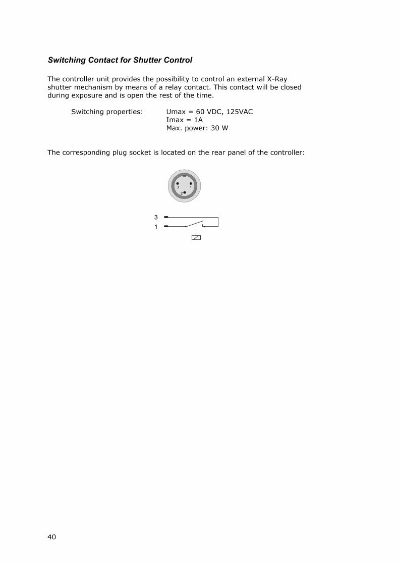
Switching Contact for Shutter Control The controller unit provides the possibility to control an external X-Ray shutter mechanism by means of a relay contact. This contact will be closed during exposure and is open the rest of the time. Switching properties: Umax = 60 VDC, 125VAC Imax = 1A Max. power: 30 W The corresponding plug socket is located on the rear panel of the controller:
13
13
2
40

G670 File Format (Program Version 3 and 4)
G670 <ProgramVersion> IsCorrected Repetitions SampleName Operator CostCentre MeasurementDate ExposureTime FileLocation /*<beginc>Comment Comment . . . Comment Comment<endc>*/ ScanStart ScanStop ScanStep Parameter1 Radiation Parameter2 I0 I1 I2 I3 I4 I5 . . .
41

42
http://www.xhuber.com/en/technotes/content.htm
Tech Notes
Calibration of the High-Temperature Capillary Heater
Topics Introduction Experiment Results
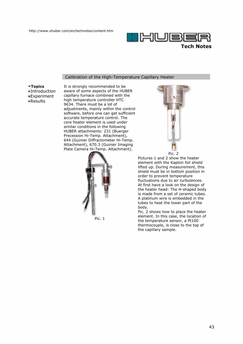
It is strongly recommended to be aware of some aspects of the HUBER capillary furnace combined with the high temperature controller HTC 9634. There must be a lot of adjustments, mainly within the control software, before one can get sufficient accurate temperature control. The core heater element is used under similar conditions in the following HUBER attachments: 231 (Buerger Precession Hi-Temp. Attachment), 644 (Guinier Diffractometer Hi-Temp. Attachment), 670.3 (Guinier Imaging Plate Camera Hi-Temp. Attachment).
Pic. 1
Pic. 2
Pictures 1 and 2 show the heater element with the Kapton foil shield lifted up. During measurement, this shield must be in bottom position in order to prevent temperature fluctuations due to air turbulences. At first have a look on the design of the heater head: The H-shaped body is made from a set of ceramic tubes. A platinum wire is embedded in the tubes to heat the lower part of the body. Pic. 2 shows how to place the heater element. In this case, the location of the temperature sensor, a Pt100 thermocouple, is close to the top of the capillary sample.
43
Introduction Evidently, due to that open design,
the temperature characteristics are extremely sensitive against all physical parameters involved: Since the sample within the capillary is heated, mainly, by radiation transfer, less by aerial energy transport, it is quite clear that the temperature seen by the sample is not the same as that seen by the point shaped metallic thermocouple. Additionally, the local temperature distribution is extremely varying in all 3 dimensions. Two adjustment procedures are necessary to get stable and reliable temperature conditions of the heater-controller system: i) The PID parameters of the controller HTC 9634 ii) The evaluation of the calibration function, i.e. the dependence of the controller's setpoint temperature versus the true sample temperature. Point i) is described in the HTC 9634 manual and has to be done first.
In the following we will refer to the item ii), only. There are some aspects fixed already by other authors or by test done at Huber's application lab. In a paper by Brown et al. /1/, a very similar heater is described for the first time, as to our knowledge. They found out, as well, what was mentioned above: The true sample temperature may differ from the set point by some 250 degrees. It was their experience and ours, commonly, that the true sample temperatures are always higher than those seen by the thermocouples. In contrary, one could believe the vice versa to be true, because the thermocouple is on top of the sample capillary closer to the heater wires. But this may result from the fact that the radiation energy absorbed by the powderised samples is higher than that absorbed by the metallic thermocouple due to Kirchhoff's Radiation Laws.
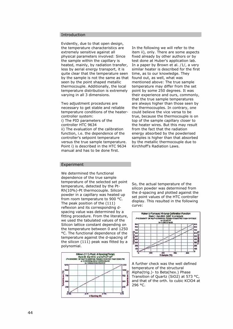
Experiment We determined the functional
dependence of the true sample temperature of the selected set point temperature, detected by the Pt-Rh(10%)-Pt thermocouple. Silicon powder in a capillary was heated up from room temperature to 900 °C. The peak position of the (111) reflexion and its corresponding d-spacing value was determined by a fitting procedure. From the literature, we used the tabulated values of the Silicon lattice constant depending on the temperature between 0 and 1250 °C. The functional dependence of the temperature against the d-spacing of the silicon (111) peak was fitted by a polynomial.
So, the actual temperature of the silicon powder was determined from the d-spacing and plotted against the set point values of the HTC controller display. This resulted in the following curve:
A further check was the well defined temperature of the structural Alpha(trig.)- to Beta(hex.) Phase Transition of Quartz (SiO2) at 573 °C, and that of the orth. to cubic KClO4 at 296 °C.
44
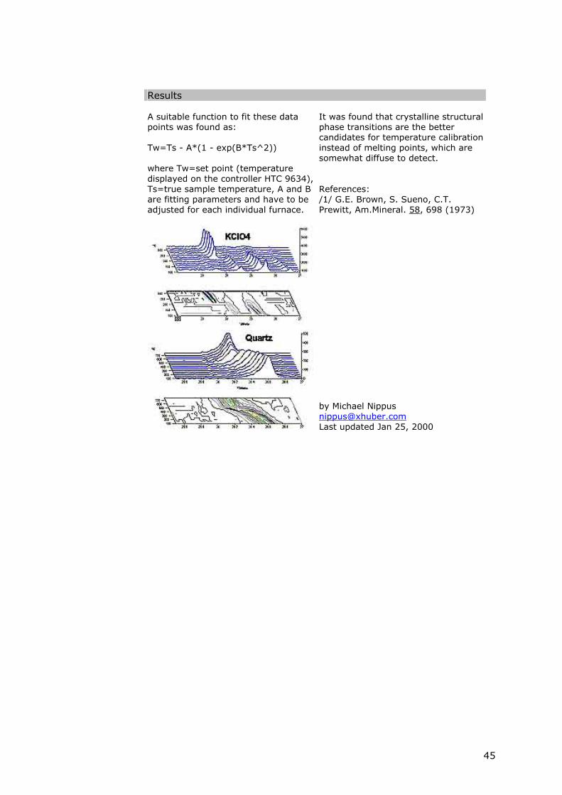
Results A suitable function to fit these data
points was found as: Tw=Ts - A*(1 - exp(B*Ts^2)) where Tw=set point (temperature displayed on the controller HTC 9634), Ts=true sample temperature, A and B are fitting parameters and have to be adjusted for each individual furnace.
It was found that crystalline structural phase transitions are the better candidates for temperature calibration instead of melting points, which are somewhat diffuse to detect. References: /1/ G.E. Brown, S. Sueno, C.T. Prewitt, Am.Mineral. 58, 698 (1973) by Michael Nippus [email protected] Last updated Jan 25, 2000
45