guitar ampli er pilot’s handbook - amazon web...
TRANSCRIPT


Guitar Ampli er
Pilot’s Handbook © 2013 Quilter Labs, LLC. All Rights Reserved
Quilter and the Quilter logo are trademarks of Quilter Laboratories, LLC

IMPORTANT SAFETY INSTRUCTIONS (PRE-FLIGHT SAFETY) 1 – Read and keep these instructions. 2 – Heed all warnings and follow all instructions. 3 – moisture. Do not use this apparatus near water. 4 – Clean only with a dry cloth. 5 – Do not install near any heat sources such as radiators, heat registers, stoves, or other
6 – Do not defeat the safety purpose of the polarized or grounding-type plug. A polarized plug has two blades with one wider than the other. A grounding plug has two blades and a grounding prong. The wide blade or third prong are provided for your safety. If the provided
rician for the replacement of the obsolete outlet. 7– Protect the power cord from being walked on or pinched, particularly plugs, convenience receptacles, and the point where they exit from the apparatus. 8 – Unplug the apparatus during lightning storms or when unused for long periods of time. 9 – The appliance coupler (or attachment plug) is the mains disconnect device and should
10 – Refer apparatus has been damaged in any way, such as power supply cord or plug is damaged, liquid has been spilled or objects have fallen into the apparatus, the apparatus has been exposed to rain or moisture, does not operate normally, or has been dropped. 11 – This device complies with Part 15 of the FCC Rules. Operation is subject to the following two conditions: (1) this device may not cause harmful interference, and (2) this device must accept any interference received, including interference that may cause undesired operation. 12 – pproved by the
Explanation of symbols
intended to alert the user to the presence of uninsulated "dangerous"
to constitute a risk of electric shock to humans.
The exclamation point within an equilateral triangle is intended to alert the user to the presence of important operating and maintenance (servicing) instructions in this manual.
CAUTION: TO REDUCE THE RISK OF ELECTRIC SHOCK, DO NOT REMOVE THE COVER. NO USER–SERVICEABLE PARTS INSIDE. REFER SERVICING TO QUALIFIED PERSONNEL.
to rain or moisture.
IMPORTANTES PRECAUCIONES DE SEGURIDAD 1 – Lea estas instrucciones y conserve estas instrucciones. 2 – Observe todas las advertencies y siga todas las instrucciones. 3 – ADVERTENCIA: Para prevenir incendios o descargas eléctricas, no exponga este equipo a la lluvia ni a la humedad. No use este aparato cerca del agua. 4 – Límpielo sólo con un paño seco. 5 – No lo instale cerca de fuentes de calor tales como radiadores, registros térmicos, estufas ni otros
6 – No anule la característica de seguridad del enchufe con conexión a tierra del cable eléctrico de tres patillas. El enchufe con conexión a tierra tiene dos hojas y una patilla de conexión a tierra. La tercera patilla se suministra para su seguridad. Si el enchufe que se le proporciona no cabe en su tomacorriente, consulte con un electricista para reemplazar el tomacorriente obsoleto. No corte la patilla de conexión a tierra ni utilice un adaptador que anule el circuito de conexión a tierra. Este aparato debe estar correctamente conectado a tierra para su seguridad. 7– Proteja el cable de alimentación para que no se camine sobre él ni se le comprima, particularmente en los enchufes, los receptáculos y el punto en donde éstos salen del aparato. 8 – Desenchufe el aparato durante tormentas eléctricas o cuando no lo vaya a usar durante periodos prolongados de tiempo. 9 – El acoplador del equipo es la desconexión de la línea principal de CA y debe permanecer fácilmente operable después de la instalación. 10 – algún daño, como cuando se daña el cable de alimentación eléctrica o el enchufe, cuando se derraman líquidos o caen objetos sobre el aparato, cuando éste ha estado expuesto a la lluvia o humedad, cuando no opere normalmente o cuando se haya caído. 11 – Este dispositivo cumple la parte 15 de las Reglas de la FCC. Su funcionamiento está sujeto a las dos condiciones siguientes: (1) este dispositivo no causará interferencias nocivas y (2) este dispositivo debe aceptar cualquier interferencia que reciba, incluidas las que puedan causar un funcionamiento no deseado.
EXPLICACIÓN DE LOS SÍMBOLOS
equilátero tiene el propósito de alertar al usuario de la presencia de voltaje “peligroso” no aislado dentro de la caja del producto,
descarga eléctrica a los seres humanos.
El signo de exclamación dentro de un triángulo equilátero tiene la intención de alertar al usuario de la presencia de importantes instrucciones de operación y mantenimiento (servicio) en este
manual.
PRECAUCIÓN: PARA REDUCIR EL RIESGO DE DESCARGA ELÉCTRICA, NO QUITE LA CUBIERTA DEL AMPLIFICADOR. EL INTERIOR NO CONTIENE PIEZAS A LAS QUE EL USUARIO PUEDA
DAR SERVICIO. REFIERA EL SERVICIO A PERSONAL CALIFICADO.
¡ADVERTENCIA!: PARA PREVENIR INCENDIOS O DESCARGAS ELÉCTRICAS, NO EXPONGA ESTE EQUIPO A LA LLUVIA NI A LA

PRÉCAUTIONS IMPORTANTES 1 – Lire et conserver ces instructions. 2 – Respecter tous les avertissements et toutes les instructions. 3 – AVERTISSEMENT : Pour écarter les risques d'incendie et d'électrocution, ne pas exposer ce matériel à la pluie ou l'humidité. Ne pas utiliser cet appareil près de l'eau. 4 – 5 – N'installer à proximité d'aucune source de chaleur comme des radiateurs, des registres de chaleur, des poêles ou d'autres appareils (y compris des amplis) qui dégagent de la chaleur. 6 –
consulter un
utiliser d'adaptateur qui rompe le circuit de mise à la terre. Par mesure de sécurité, cet appareil doit être correctement mis à la terre. 7– Protéger le cordon d'alimentation pour que personne ne puisse marcher dessus, qu'il ne
d'émergence du cordon de l'appareil. 8 – Débrancher l'appareil en cas d'orage électrique ou lorsqu'il est inutilisé pendant longtemps. 9 – Le coupleur de l'appareil est l'interrupteur général et il doit être immédiatement utilisable après l'installation. 10 – e lorsque l'appareil a été endommagé d'une manière quelconque, par exemple endommagement du
l'intérieur de l'appareil, exposition de l'appareil à la pluie ou l'humidité, fonctionnement anormal ou chute de l'appareil. 11 – Ce matériel est conforme à la partie 15 des règlements de la FCC. Le fonctionnement est soumis aux deux conditions suivantes : (1) Ce matériel ne doit pas causer de brouillage préjudiciable, et (2) Ce matériel doit accepter tout brouillage reçu, y compris le brouillage pouvant provoquer un mauvais fonctionnement.
EXPLICATION DES SYMBOLES
l'utilisateur la présence d'une tension « dangereuse » non isolée dans le
ue d'électrocution pour l'homme.
Le point d'exclamation dans un triangle équilatéral a pour objet de signaler à l'utilisateur la présence d'instructions importantes d'utilisation et de maintenance (réparation) dans ce manuel.
ATTENTION : POUR RÉDUIRE LES RISQUE D'ÉLECTROCUTION, NE PAS RETIRER LE CAPOT DE L'AMPLIFICATEUR. AUCUNE PIÈCE RÉPARABLE PAR L'UTILISATEUR À L'INTÉRIEUR. CONFIER TOUTE RÉPARATION À UN PERSONNEL QUALIFIÉ.
AVERTISSSSEMENT!: POUR ÉCARTER LES RISQUES D’INCENDIE ET D’ÉLECTROCUTION, NE PAS EXPOSER CE MATÉRIEL À LA PLUIE OU L’HUMIDITÉ.

WICHTIGE SICHERHEITSVORKEHRUNGEN 1 – Diese Anleitung sorgfältig durchlesen. Diese Anleitung gut aufbewahren. 2 – Alle Warnhinweise beachten. Alle Anweisungen befolgen. 3 – ACHTUNG: Zur Vermeidung von Bränden und Stromschlägen darf diese Ausrüstung weder Regen noch Feuchtigkeit ausgesetzt werden. Dieses Gerät nicht in Wassernähe verwenden. 4 – Nur mit einem trockenen Tuch reinigen. 5 – Nicht in der Nähe von Wärmequellen wie Heizkörpern, Warmluftschiebern, Öfen oder anderen Geräten (einschließlich Verstärkern) aufstellen, die Wärme abstrahlen. 6 – Die Sicherheitsfunktion des dreipoligen (nur für USA/Kanada) Schutzkontaktsteckers am Edison-Netzkabel nicht außer Kraft setzen. Der Schutzkontaktstecker besitzt zwei Stifte und einen Erdungspol (nur für USA/Kanada). Der dritte Stift dient der Sicherheit. Wenn der im Lieferumfang enthaltene Stecker nicht in Ihre Steckdose passt, ist diese veraltet und muss von einem Elektriker ersetzt werden. Den Erdungsstift nicht abschneiden und keinen Adapter verwenden, der den Erdungsschaltkreis unterbricht. Dieses Gerät muss zu Ihrer Sicherheit ordnungsgemäß geerdet werden.. 7– Das Netzkabel so verlegen, dass niemand darauf treten oder es eingeklemmt werden kann. Dies gilt insbesondere für Stecker, Steckdosen und die Stelle, an der das Kabel aus dem Gerät austritt. 8 – Das Netzkabel des Geräts während Gewittern, oder wenn es längere Zeit nicht benutzt wird, von der Steckdose abziehen. 9 – Der Gerätekoppler fungiert als Netzstrom-Trennvorrichtung und sollte nach der Installation jederzeit betriebsfähig sein. 10 – ren lassen. Das Gerät muss immer dann gewartet werden, wenn es auf irgendeine Weise beschädigt wurde, z. B. wenn das Netzkabel oder der Netzstecker beschädigt ist, Flüssigkeit auf dem Gerät verschüttet wurde oder Gegenstände in das Gerät gefallen sind, das Gerät Regen oder Feuchtigkeit ausgesetzt wurde, es nicht normal funktioniert oder fallen gelassen wurde. 11 – Dieses Gerät stimmt mit Abschnitt 15 der FCC Vorschriften überein. Der Betrieb des Geräts unterliegt folgenden zwei Bedingungen: (1) dieses Gerät darf keine schädliche Interferenz verursachen, und (2) dieses Gerät soll alle Interferenz akzeptieren, die es empfängt, einschließlich
SYMBOLERKLÄRUNG
Das aus einem Blitz mit einer Pfeilspitze bestehende Symbol in einem Dreieck soll den Benutzer auf das Vorhandensein nicht isolierter, gefährlicher Spannungen innerhalb des Gehäuses aufmerksam machen, die stark genug sein können, um einen elektrischen Schlag
abzugeben.
Das Ausrufezeichen in einem Dreieck soll den Benutzer auf das Vorhandensein wichtiger Betriebs- und Wartungsanleitungen in diesem Handbuch aufmerksam machen.
VORSICHT: ZUR REDUZIERUNG DES STROMSCHLAGRISIKOS DIE ABDECKUNG DES VERSTÄRKERS NICHT ABNEHMEN. KEINE VOM BENUTZER ZU WARTENDEN INNENKOMPONENTEN. FÜR ALLE WARTUNGSARBEITEN DAFÜR QUALIFIZIERTES PERSONAL EINSETZEN.
ACHTUNG!: Zur Vermeidung von Bränden und Stromschlägen darf diese Ausrüstung weder Regen noch Feuchtigkeit ausgesetzt werden.


Role of the Quilter Aviation Administration The Quilter Aviation Administration (QAA) is self-empowered to provide
ation. This is
formerly referred to as the “Tone Standards”.
Role of the Flight Instructor
Aviation safety. The QAA has adopted an operational training concept that ensures complete responsibility for training the Aviator student in all necessary areas of knowledge and skill required to operate safely and get outstanding tone. This training will include tonemanship skills, pilot judgment, decision making, and accepted good operating practices.
required to pass rigid knowledge and practical tests, and demonstrate the
showing continued success in tonemanship skills.
Flight safety practices In the interest of safety and good tonemanship skills, there are certain
Chapter 2

Ground operations Visually inspect your cockpit.
Front Panel
Ensure that all of your instruments are in good working order.
Chapter 3
Visually inspect your cockpit.

Ground operations Visually inspect your cockpit.
Front Panel
Ensure that all of your instruments are in good working order.
Chapter 3
Visually inspect your cockpit.


FLIGHT INSTRUMENT PANEL: OPERATING CONTROLS
Aux Input (Channel 1 only)
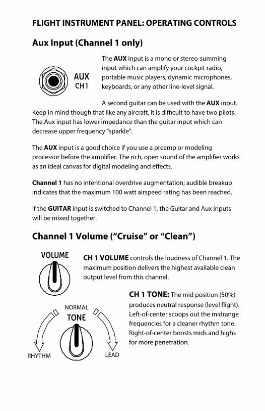
The AUX input is a mono or stereo-summing input which can amplify your cockpit radio, portable music players, dynamic microphones, keyboards, or any other line-level signal.
A second guitar can be used with the AUX input. Keep in mind thThe Aux input has lower impedance than the guitar input which can decrease upper frequency “sparkle”.
The AUX input is a good choice if you use a preamp or modeling processor before the amplias an ideal
Channel 1 has no intentional overdrive augmentation; audible breakup indicates that the maximum 100 watt airspeed rating has been reached.
If the GUITAR input is switched to Channel 1, the Guitar and Aux inputs will be mixed together.
Channel 1 Volume (“Cruise” or “Clean”)
CH 1 VOLUME controls the loudness of Channel 1. Themaximum position delivers the highest available clean output level from this channel.
CH 1 TONE: The mid position (50%) produces neutral response Left-of-center scoops out the midrange frequencies for a cleaner rhythm tone. Right-of-center boosts mids and highs for more penetration.

Guitar Input (Channel 1/2)
The GUITAR input is tailored for electric guitars and features a 2 meg input impedance that preserves the delicate overtones of standard magnetic pickups.
The guitar input can be routed to either Channel 1 or 2 by pressing the SELECT button on the front panel or the CH 1/2 footswitch.
Channel Select Annunciator Lights
A pair of lighted indicators show which channel is receiving the guitar signal.
Press the SELECT button to change the channel assignment. (NOTE: when the footswitch is plugged in, it overrides the CH 1/2 SELECT button).
Channel 2 Gain (“Throttle” or “Prop Speed”)
The channel 2 GAIN control sets the indicated airspeed for Ch 2, ranging from clean cruising to mild overdrive to full emergency dive.
At low settings, the tone will remain clean. Mid settings will allow louder notes to start breaking up. High settings will produce full overdrive on
all notes.
The threshold of overdrive depends on playing style, pickup type and the guitar’s volume control.
As the GAIN is increased, the “airspeed” the MASTER control to adjust the overall loudness or “altitude”.

Channel 2 Tone Controls (TONE TRIMS)
The BASS, MID and TREBLE controls adjust frequency equalization or tone balance for Channel 2. The controls are active boost/cut controls with a neutral response at 50% (straight up).
The tone trim controls will help you achieve level and neutral flight regardless of your operating environment, while compensating for outside conditions such as the guitar’s tonal balance, and the conditions in the airspace.
Unlike traditional attitude-adjustment controls, the Aviator tone controls are totally neutral in their center position. This allows the pilot to observe the guitar’s natural tone prior to making adjustments. Many are surprised to discover the pleasures of ight in the neutral position, and may only need to make adjustments depending on the room characteristics.
Channel 2 Master Volume (ALTITUDE)
MASTER regulates the overall loudness of Channel 2 without s tone or overdrive. The lower settings are suitable for simulations while gaining mastery of the controls. High Master settings unleash the Aviator’s full power for operating in
controlled airspaces.
Channel 2 Hi-Cut (CONTROL ATTACK)
Reverb Section
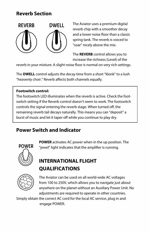
The Aviator uses a premium digital reverb chip with a smoother decay
spring tank. The reverb is voiced to “soar” nicely above the mix.
The REVERB control allows you to increase the richness (Level) of the
reverb in your mixture.
The DWELL control adjusts the decay time from a short “klonk” to a lush “heavenly choir.”
Footswitch control: The footswitch LED illuminates when the reverb is active. Check the foot-switch setting if the Reverb control doesn’t seem to work. The footswitch controls the signal entering remaining reverb tail decays naturally. This means you can “deposit” a
.
Power Switch and Indicator
POWER activates AC power when in the up position. The “jewel” light indicates that running.
INTERNATIONAL FLIGHT QUALIFICATIONS The Aviator can be used on all world-wide AC voltages from 100 to 250V, which allows you to navigate just about anywhere on the planet without an Auxiliary Power Unit. No adjustments are required to operate in other countries.
Simply obtain the correct AC cord for the local AC service, plug in and engage POWER.

Locking IEC Power Cord
locks into the AC inlet to reduce the chance it will come unplugged during use. Press the yellow button on the cord to release it. Any
normal 3-prong IEC cord may also be used if required. Always ensure that the ground contact is intact on both the cord and receptacle.
Dual-Prop Operation (Extension Speaker Outputs)
come with the internal speaker plugged into the INT SPEAKER output. An external 8 ohm speaker may be used in place of the internal speaker by unplugging this cable and connecting the external speaker. An external 4 ohm speaker cabinet should be connected to the EXT SPEAKER output.
To use two speaker cabinets simultaneously, connect an 8 ohm cabinet (or the internal speaker) to the INT SPEAKER output, and connect a 4-8 ohm extension speaker with a minimum of 200 watts continuous power handling to the EXT SPEAKER output. Internal circuitry adjusts the output impedance to split the power between the two outputs.
300 watts peak, well beyond the capacity of many single speakers. We recommend Quilter extension cabinets with “full-altitude-tested” speakers. Quilter Labs will
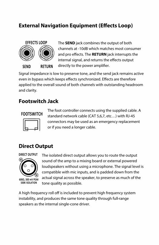
External Navigation Equipment ( )
The SEND jack combines the output of both channels at -10dB which matches most consumer
The RETURN jack interrupts the internal signal, and directly to the power
Signal impedance is low to preserve tone, and the send jack remains active even in bypass are therefore applied to the overall sound of both channels with outstanding headroom and clarity.
Footswitch Jack The foot controller connects using the supplied cable. A standard network cable (CAT 5,6,7, etc…) with RJ-45 connectors may be used as an emergency replacement or if you need a longer cable.
Direct Output The isolated direct output allows you to route the output sound of the amp to a mixing board or external powered loudspeakers without using a microphone. The signal level is compatible with mic inputs, and is padded down from the actual signal across the speaker, to preserve as much of the tone quality as possible.
A high frequency roll is included to prevent high frequency system instability, and produces the same tone quality through full-range speakers as the internal single-cone driver.

The optional foot controller allows you to route the GUITAR input to Channel 1 or 2, and to bypass the reverb, without having to access
Plug one end of the supplied cable into the jack on the foot controller. Plug the other end of the cable into the
press the plastic tab on the plug to unlock it.
Channel Switching When the footswitch LED is on, the GUITAR input is routed to the high gain Channel 2, as also shown on the front panel indicator. When the footswitch LED GUITAR input is routed to Channel 1, and the CH 1 front panel indicator will be lit. NOTE: While the footswitch is connected, the front panel SELECT button is non-operational.
Reverb Bypass When the footswitch LED is on, the Reverb is activated. The amount of Reverb is set by the REVERB knob. If the REVERB knob is at its minimum position (fully counter-clockwise), Reverb will not be heard.
The FC- only. There are no user-serviceable parts inside the foot controller. If the device is exposed to a liquid spill or excessive moisture, unplug it immediately and allow to dry thoroughly before using.

(All Models)
Power Output: Channel 1: 100 W RMS Channel 2: 100 W RMS Total: 200 W RMS
AC Power Req.: 100–240V, 50–60 Hz, 250 W maximum. Input Connections: ¼ " mono jacks (Aux and Guitar) Input Impedance: A UX: 100K ohms
GUITAR: 2M ohms S end: ¼" mono, -10dB, 1K ohms
Return: ¼" mono, -10dB, 50K ohms Speaker 1 Output: 8 ohms, 200 W minimum rating Speaker 2 Output: 4-8 ohms, 200 W minimum rating Ultralight (8 inch) 22.6 Pounds (10.3 Kg) Open Cockpit (12” open back) 33.8 Pounds (15.4 Kg) The twin (2x10” open back) 33.8 Pounds (15.4 Kg)
Note: Power ratings are provided by the loudspeaker manufacturer and are only a
selections using a lengthy full power test that ensures that the speaker can stand


Clean the outer surfaces with a clean, damp cloth or vacuum with a soft brush. Never use any abrasives, harsh cleaners or solvents.
modern industrial processes that greatly reduce production defects. Each goes through an intensive testing process before it leaves the
facto There are no user-be performed by a trained service professional.
-ventilated environment and protect from external heat sources such as furnaces or direct sunlight.
Prolonged high-volume playing causes heat buildup in the speaker which d it necessary to consistently use the
amp at full Master volume, we recommend using an extension speaker to prolong speaker life and improve sound coverage.
Factory Service
please visit www.quilterlabs.com you do not have access to the website, you may send a request by letter to
include the serial number of the amplifier and a copy of your sales receipt.
-authorized service technician may void your warranty.

LIMITED TRANSFERABLE WARRANTY
IMPORTANT: PLEASE READ THIS DOCUMENT COMPLETELY. IT CONTAINSIMPORTANT INFORMATION ABOUT YOUR RIGHTS AND OBLIGATIONS, AS WELL ASLIMITATIONS AND EXCLUSIONS THAT MAY OR MAY NOT APPLY TO YOU. BYACCEPTING DELIVERY OF THE PRODUCT(S), YOU AGREE TO BE BOUND BY ANDACCEPT THESE TERMS AND CONDITIONS. Quilter Laboratories, LLC (Quilter Labs) guarantees its products to be free from defective material and/or workmanship and will replace defective parts and repair malfunctioningproducts under this warranty when the defect occurs under normal installation and use—provided the unit is returned to our factory via pre-paid transportation with a copy of proofof purchase. (i.e. sales receipt). This warranty provides that the examination of the return product must indicate, in our judgment, a manufacturing defect. This warranty does not extend to any product which has been subjected to misuse, neglect, accident, or where the date code or serial number has been defaced or removed. Quilter Labs shall not be liable for
This limited warranty is freely transferable during the term of the warranty period. The warranty on Quilter products is NOT VALID if the products have been purchased from an unauthorized dealer/online e-tailer, or if the factory serial number has been removed, defaced, or replaced in any way. Customers may have additional rights, which vary from state to state or from country to country. In the event that a provision of this limited warranty is void, prohibited or
limited warranty in the United States is valid for a period of three (3) years from date ofpurchase except that foot controllers, covers, cabinets, handles, and cabinet hardware are warranted for a period of one (1) year and speakers, and all other included accessory products for a period of ninety (90) days from date of purchase. IMPORTANT: PLEASE RETAIN YOUR SALES RECEIPT OR ONLINE ORDER RECORD, AS IT IS YOUR PROOF OF PURCHASE COVERING YOUR LIMITED WARRANTY. TO TRANSFER THE WARRANTY TO A SUBSEQUENT PURCHASER, YOU MUST ENDORSE THE SALE OF THE PRODUCT TO THE SUBSEQUENT PURCHASER ON THE FRONT OF THE SALES RECEIPT. THIS LIMITED WARRANTY IS VOID WITHOUT SUCH ENDORSED SALES RECEIPT. Defective products that qualify for coverage under this warranty will be repaired or replaced, (at Quilter Labs’ discretion) with a like or comparable product, without charge. To receive warranty service, return the complete product to Quilter Labs, LLC, with proof of purchase, during the applicable warranty period. The Quilter Labs Dealer from whom you purchased your product may also be authorized for warranty service contact when service is required. TRANSPORTATION COSTS ARE NOT INCLUDED IN THIS LIMITED WARRANTY. Any repair or service performed by any person or entity other than an Authorized Quilter Labs Electronics Service Center is not covered by this limited warranty. Other questions regarding this warranty can be answered by calling (714) 519-6114 or bycontacting your authorized Quilter distributor. Email: [email protected]
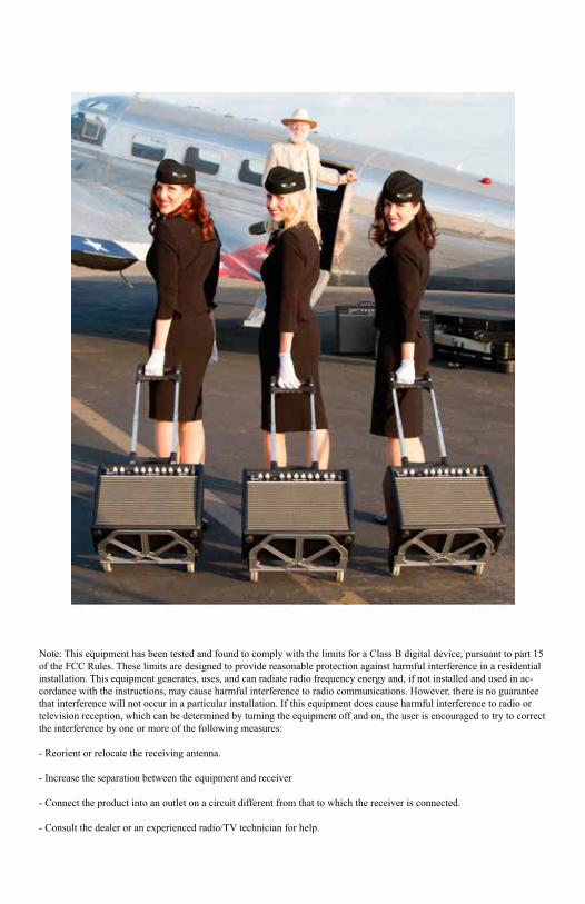
Note: This equipment has been tested and found to comply with the limits for a Class B digital device, pursuant to part 15 of the FCC Rules. These limits are designed to provide reasonable protection against harmful interference in a residential installation. This equipment generates, uses, and can radiate radio frequency energy and, if not installed and used in ac-cordance with the instructions, may cause harmful interference to radio communications. However, there is no guarantee that interference will not occur in a particular installation. If this equipment does cause harmful interference to radio or television reception, which can be determined by turning the equipment off and on, the user is encouraged to try to correct the interference by one or more of the following measures:
- Reorient or relocate the receiving antenna.
- Increase the separation between the equipment and receiver
- Connect the product into an outlet on a circuit different from that to which the receiver is connected.
- Consult the dealer or an experienced radio/TV technician for help.