gujarat energy transmission corporation ltd. office/080816/24_ fqp... · gujarat energy...
TRANSCRIPT
1
GUJARAT ENERGY TRANSMISSION CORPORATION LTD.
STANDARD FIELD QUALITY PLAN TRANSMISSION LINES
01 June 2014
Engineering Cell
Annx. 6 added
CE (Engineering)
Revision Date
Submitted By Approved By Rev. History
DOCUMENT NO. GETCO/E/FQP/LINE/001
2
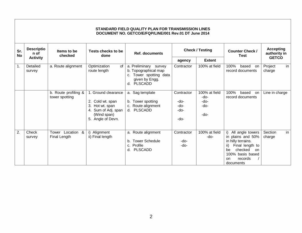
STANDARD FIELD QUALITY PLAN FOR TRANSMISSION LINES DOCUMENT NO. GETCO/E/FQP/LINE/001 Rev.01 DT June 2014
Check / Testing Sr. No
Description of
Activity Items to be
checked Tests checks to be
done Ref. documents
agency Extent
Counter Check / Test
Accepting authority in
GETCO
1. Detailed survey
a. Route alignment Optimization of route length
a. Preliminary survey b. Topographical map c. Tower spotting data
given by Engg. d. PLSCADD
Contractor 100% at field 100% based on record documents
Project in charge
b. Route profiling & tower spotting
1. Ground clearance 2. Cold wt. span 3. Hot wt. span 4. Sum of Adj. span (Wind span) 5. Angle of Devn.
a. Sag template b. Tower spotting c. Route alignment d. PLSCADD
Contractor -do- -do- -do- -do-
100% at field -do- -do- -do- -do-
100% based on record documents
Line in charge
2. Check survey
Tower Location & Final Length
i) Alignment ii) Final length
a. Route alignment b. Tower Schedule c. Profile d. PLSCADD
Contractor
-do- -do-
100% at field -do-
i) All angle towers in plains and 50% in hilly terrains. ii) Final length to be checked on 100% basis based on records / documents
Section in charge
3
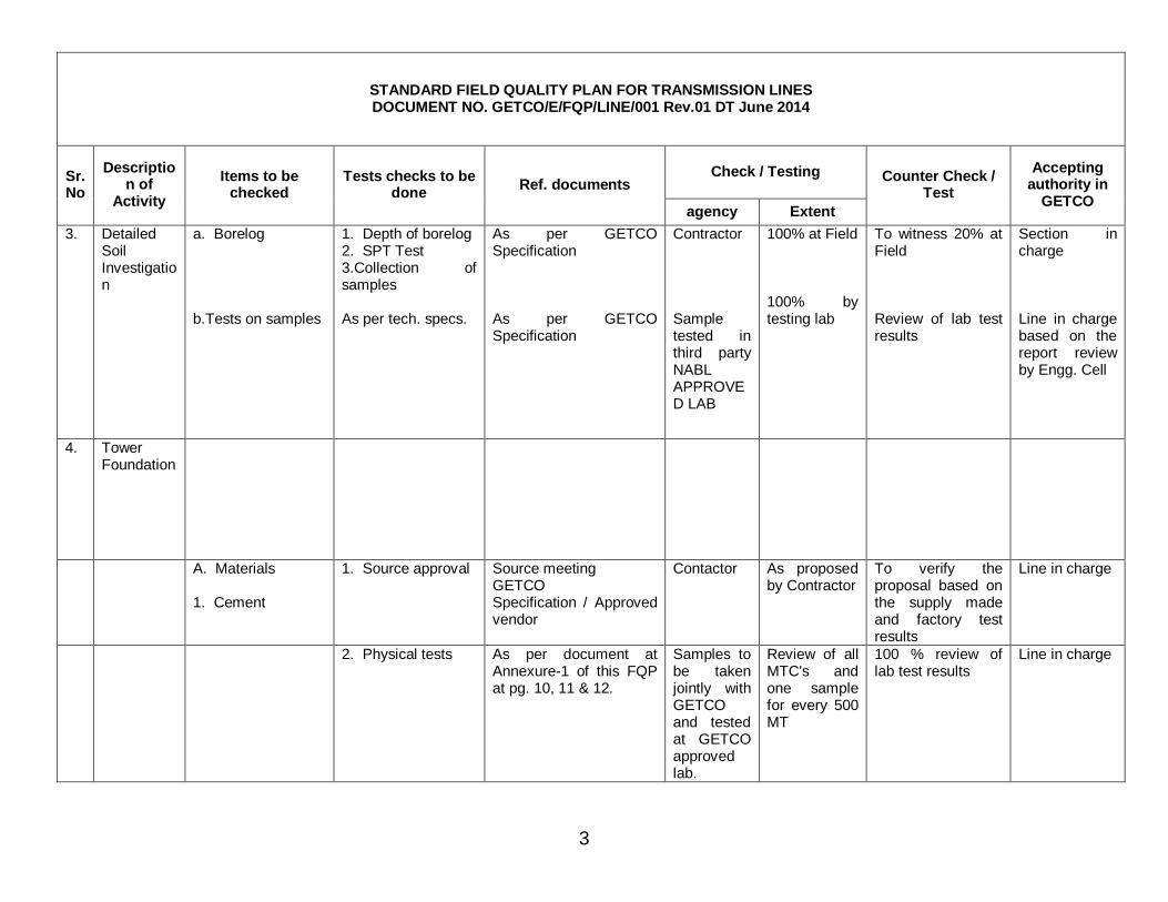
STANDARD FIELD QUALITY PLAN FOR TRANSMISSION LINES DOCUMENT NO. GETCO/E/FQP/LINE/001 Rev.01 DT June 2014
Check / Testing Sr. No
Description of
Activity Items to be
checked Tests checks to be
done Ref. documents
agency Extent
Counter Check / Test
Accepting authority in
GETCO
3. Detailed Soil Investigation
a. Borelog b.Tests on samples
1. Depth of borelog 2. SPT Test 3.Collection of samples As per tech. specs.
As per GETCO Specification As per GETCO Specification
Contractor Sample tested in third party NABL APPROVED LAB
100% at Field 100% by testing lab
To witness 20% at Field Review of lab test results
Section in charge Line in charge based on the report review by Engg. Cell
4. Tower Foundation
A. Materials 1. Cement
1. Source approval Source meeting GETCO Specification / Approved vendor
Contactor As proposed by Contractor
To verify the proposal based on the supply made and factory test results
Line in charge
2. Physical tests As per document at Annexure-1 of this FQP at pg. 10, 11 & 12.
Samples to be taken jointly with GETCO and tested at GETCO approved lab.
Review of all MTC's and one sample for every 500 MT
100 % review of lab test results
Line in charge
4
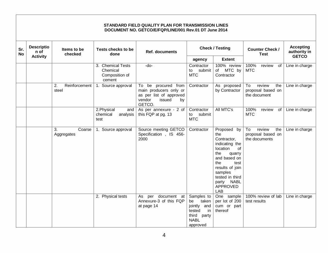
STANDARD FIELD QUALITY PLAN FOR TRANSMISSION LINES DOCUMENT NO. GETCO/E/FQP/LINE/001 Rev.01 DT June 2014
Check / Testing Sr. No
Description of
Activity Items to be
checked Tests checks to be
done Ref. documents
agency Extent
Counter Check / Test
Accepting authority in
GETCO
3. Chemical Tests Chemical Composition of cement
-do- Contractor to submit MTC
100% review of MTC by Contractor
100% review of MTC
Line in charge
2. Reinforcement steel
1. Source approval To be procured from main producers only or as per list of approved vendor issued by GETCO.
Contractor As proposed by Contractor
To review the proposal based on the document
Line in charge
2.Physical and chemical analysis test
As per annexure - 2 of this FQP at pg. 13
Contractor to submit MTC
All MTC's 100% review of MTC
Line in charge
3. Coarse Aggregates
1. Source approval Source meeting GETCO Specification , IS 456-2000
Contractor Proposed by the Contractor, indicating the location of the quarry and based on the test results of join samples tested in third party NABL APPROVED LAB
To review the proposal based on the documents
Line in charge
2. Physical tests As per document at Annexure-3 of this FQP at page 14
Samples to be taken jointly and tested in third party NABL approved
One sample per lot of 200 cum or part thereof
100% review of lab test results
Line in charge
5
STANDARD FIELD QUALITY PLAN FOR TRANSMISSION LINES DOCUMENT NO. GETCO/E/FQP/LINE/001 Rev.01 DT June 2014
Check / Testing Sr. No
Description of
Activity Items to be
checked Tests checks to be
done Ref. documents
agency Extent
Counter Check / Test
Accepting authority in
GETCO
lab
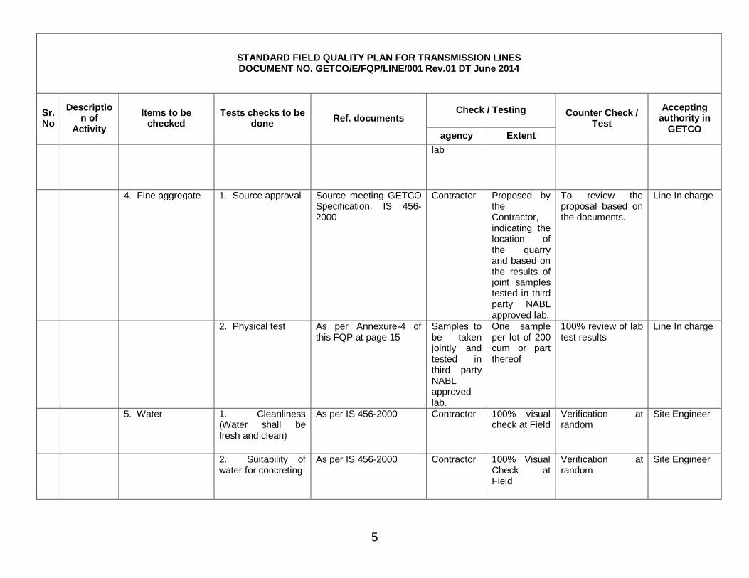
4. Fine aggregate 1. Source approval Source meeting GETCO Specification, IS 456-2000
Contractor Proposed by the Contractor, indicating the location of the quarry and based on the results of joint samples tested in third party NABL approved lab.
To review the proposal based on the documents.
Line In charge
2. Physical test As per Annexure-4 of this FQP at page 15
Samples to be taken jointly and tested in third party NABL approved lab.
One sample per lot of 200 cum or part thereof
100% review of lab test results
Line In charge
5. Water 1. Cleanliness (Water shall be fresh and clean)
As per IS 456-2000 Contractor 100% visual check at Field
Verification at random
Site Engineer
2. Suitability of water for concreting
As per IS 456-2000 Contractor 100% Visual Check at Field
Verification at random
Site Engineer
6
STANDARD FIELD QUALITY PLAN FOR TRANSMISSION LINES DOCUMENT NO. GETCO/E/FQP/LINE/001 Rev.01 DT June 2014
Check / Testing Sr. No
Description of
Activity Items to be
checked Tests checks to be
done Ref. documents
agency Extent
Counter Check / Test
Accepting authority in
GETCO
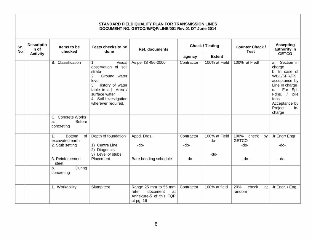
B. Classification 1. Visual observation of soil strata 2. Ground water level 3. History of water table in adj. Area / surface water 4. Soil Investigation wherever required.
As per IS 456-2000 Contractor 100% at Field 100% at Fiedl a. Section in charge b. In case of WBC/SFR/FS acceptance by Line In charge c. For Spl. Fdns. / pile fdns. Acceptance by Project In-charge
C. Concrete Works a. Before concreting
1. Bottom of excavated earth 2. Stub setting 3. Reinforcement steel
Depth of foundation 1) Centre Line 2) Diagonals 3) Level of stubs Placement
Appd. Drgs. -do- Bare bending schedule
Contractor -do- -do-
100% at Field -do- -do-
100% check by GETCO -do- -do-
Jr.Engr/ Engr. -do- -do-
b. During concreting
1. Workability Slump test Range 25 mm to 55 mm refer document at Annexure-5 of this FQP at pg. 16
Contractor 100% at field 20% check at random
Jr.Engr. / Eng.
7
STANDARD FIELD QUALITY PLAN FOR TRANSMISSION LINES DOCUMENT NO. GETCO/E/FQP/LINE/001 Rev.01 DT June 2014
Check / Testing Sr. No
Description of
Activity Items to be
checked Tests checks to be
done Ref. documents
agency Extent
Counter Check / Test
Accepting authority in
GETCO
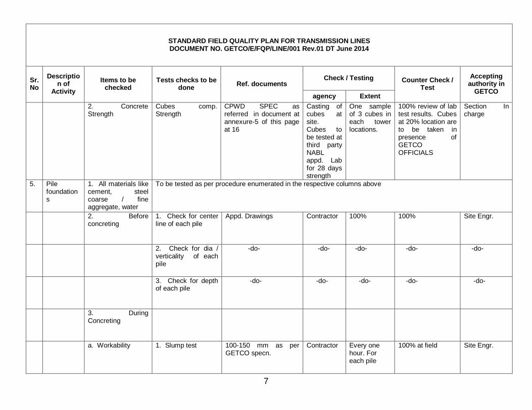
2. Concrete Strength
Cubes comp. Strength
CPWD SPEC as referred in document at annexure-5 of this page at 16
Casting of cubes at site. Cubes to be tested at third party NABL appd. Lab for 28 days strength
One sample of 3 cubes in each tower locations.
100% review of lab test results. Cubes at 20% location are to be taken in presence of GETCO OFFICIALS
Section In charge
5. Pile foundations
1. All materials like cement, steel coarse / fine aggregate, water
To be tested as per procedure enumerated in the respective columns above
2. Before concreting
1. Check for center line of each pile
Appd. Drawings Contractor 100% 100% Site Engr.
2. Check for dia / verticality of each pile
-do- -do- -do- -do- -do-
3. Check for depth of each pile
-do- -do- -do- -do- -do-
3. During Concreting
a. Workability 1. Slump test 100-150 mm as per GETCO specn.
Contractor Every one hour. For each pile
100% at field Site Engr.
8
STANDARD FIELD QUALITY PLAN FOR TRANSMISSION LINES DOCUMENT NO. GETCO/E/FQP/LINE/001 Rev.01 DT June 2014
Check / Testing Sr. No
Description of
Activity Items to be
checked Tests checks to be
done Ref. documents
agency Extent
Counter Check / Test
Accepting authority in
GETCO
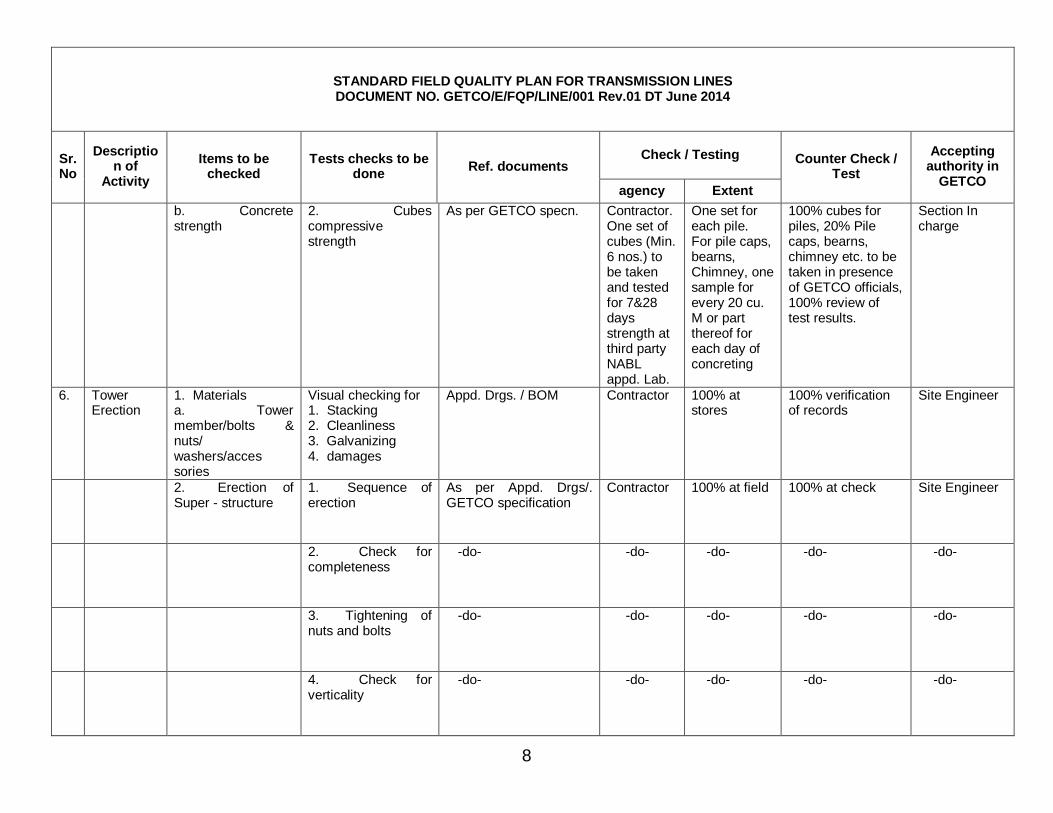
b. Concrete strength
2. Cubes compressive strength
As per GETCO specn. Contractor. One set of cubes (Min. 6 nos.) to be taken and tested for 7&28 days strength at third party NABL appd. Lab.
One set for each pile. For pile caps, bearns, Chimney, one sample for every 20 cu. M or part thereof for each day of concreting
100% cubes for piles, 20% Pile caps, bearns, chimney etc. to be taken in presence of GETCO officials, 100% review of test results.
Section In charge
6. Tower Erection
1. Materials a. Tower member/bolts & nuts/ washers/acces sories
Visual checking for 1. Stacking 2. Cleanliness 3. Galvanizing 4. damages
Appd. Drgs. / BOM Contractor 100% at stores
100% verification of records
Site Engineer
2. Erection of Super - structure
1. Sequence of erection
As per Appd. Drgs/. GETCO specification
Contractor 100% at field 100% at check Site Engineer
2. Check for completeness
-do- -do- -do- -do- -do-
3. Tightening of nuts and bolts
-do- -do- -do- -do- -do-
4. Check for verticality
-do- -do- -do- -do- -do-
9
STANDARD FIELD QUALITY PLAN FOR TRANSMISSION LINES DOCUMENT NO. GETCO/E/FQP/LINE/001 Rev.01 DT June 2014
Check / Testing Sr. No
Description of
Activity Items to be
checked Tests checks to be
done Ref. documents
agency Extent
Counter Check / Test
Accepting authority in
GETCO
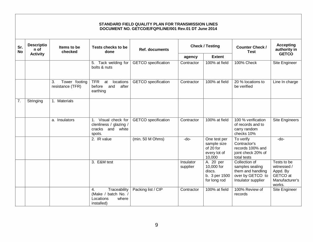
5. Tack welding for bolts & nuts
GETCO specification Contractor 100% at field 100% Check Site Engineer
3. Tower footing resistance (TFR)
TFR at locations before and after earthing
GETCO specification Contractor 100% at field 20 % locations to be verified
Line In charge
7. Stringing 1. Materials
a. Insulators 1. Visual check for clenliness / glazing / cracks and white spots.
GETCO specification Contractor 100% at field 100 % verification of records and to carry random checks 10%
Site Engineers
2. IR value (min. 50 M Ohms) -do- One test per sample size of 20 for every lot of 10,000
To verify Contractor's records 100% and joint check 20% of total tests
-do-
3. E&M test Insulator supplier
A. 20 per 10,000 for discs. b. 3 per 1500 for long rod
Collection of samples sealing them and handling over by GETCO to Insulator supplier
Tests to be witnessed / Appd. By GETCO at Manufacturer's works.
4. Traceability (Make / batch No. / Locations where installed)
Packing list / CIP Contractor 100% at field 100% Review of records
Site Engineer
10
STANDARD FIELD QUALITY PLAN FOR TRANSMISSION LINES DOCUMENT NO. GETCO/E/FQP/LINE/001 Rev.01 DT June 2014
Check / Testing Sr. No
Description of
Activity Items to be
checked Tests checks to be
done Ref. documents
agency Extent
Counter Check / Test
Accepting authority in
GETCO
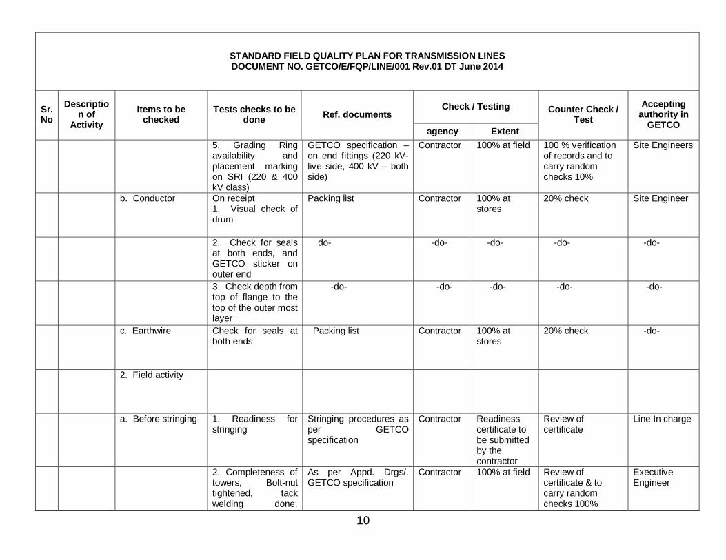
5. Grading Ring availability and placement marking on SRI (220 & 400 kV class)
GETCO specification – on end fittings (220 kV-live side, 400 kV – both side)
Contractor 100% at field 100 % verification of records and to carry random checks 10%
Site Engineers
b. Conductor On receipt 1. Visual check of drum
Packing list Contractor 100% at stores
20% check Site Engineer
2. Check for seals at both ends, and GETCO sticker on outer end
do- -do- -do- -do- -do-
3. Check depth from top of flange to the top of the outer most layer
-do- -do- -do- -do- -do-
c. Earthwire Check for seals at both ends
Packing list Contractor 100% at stores
20% check -do-
2. Field activity
a. Before stringing 1. Readiness for stringing
Stringing procedures as per GETCO specification
Contractor Readiness certificate to be submitted by the contractor
Review of certificate
Line In charge
2. Completeness of towers, Bolt-nut tightened, tack welding done.
As per Appd. Drgs/. GETCO specification
Contractor 100% at field Review of certificate & to carry random checks 100%
Executive Engineer
11
STANDARD FIELD QUALITY PLAN FOR TRANSMISSION LINES DOCUMENT NO. GETCO/E/FQP/LINE/001 Rev.01 DT June 2014
Check / Testing Sr. No
Description of
Activity Items to be
checked Tests checks to be
done Ref. documents
agency Extent
Counter Check / Test
Accepting authority in
GETCO
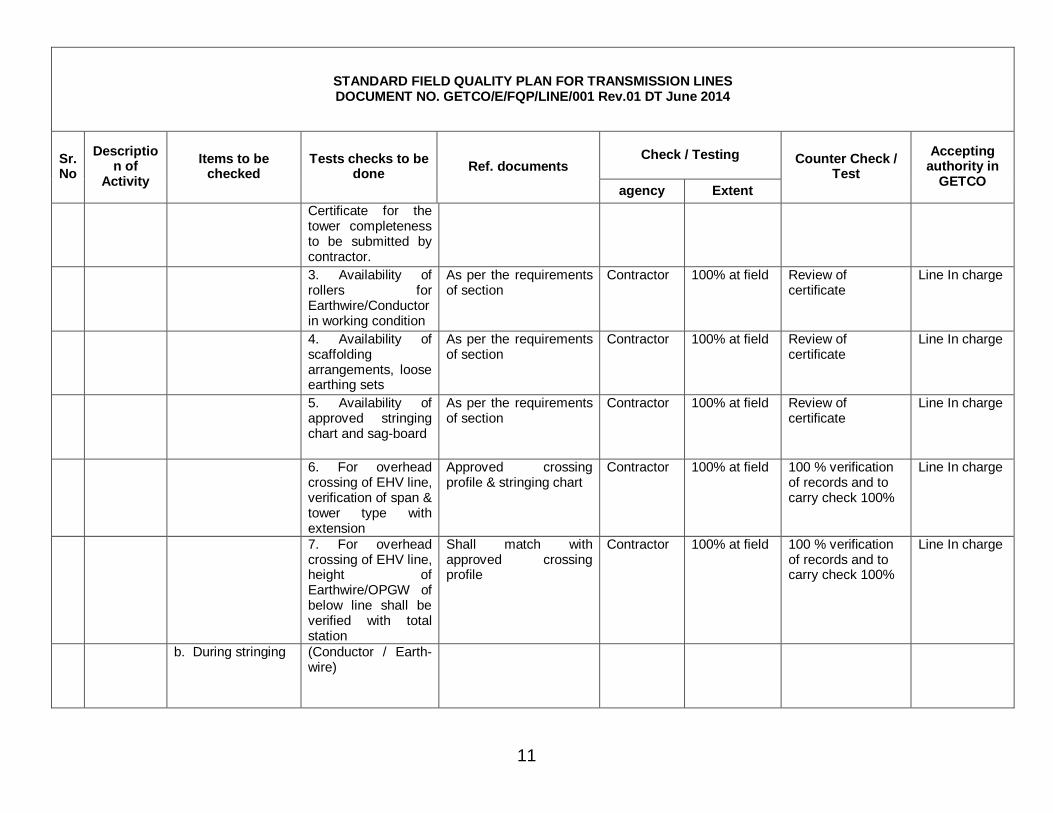
Certificate for the tower completeness to be submitted by contractor.
3. Availability of rollers for Earthwire/Conductor in working condition
As per the requirements of section
Contractor 100% at field Review of certificate
Line In charge
4. Availability of scaffolding arrangements, loose earthing sets
As per the requirements of section
Contractor 100% at field Review of certificate
Line In charge
5. Availability of approved stringing chart and sag-board
As per the requirements of section
Contractor 100% at field Review of certificate
Line In charge
6. For overhead crossing of EHV line, verification of span & tower type with extension
Approved crossing profile & stringing chart
Contractor 100% at field 100 % verification of records and to carry check 100%
Line In charge
7. For overhead crossing of EHV line, height of Earthwire/OPGW of below line shall be verified with total station
Shall match with approved crossing profile
Contractor 100% at field 100 % verification of records and to carry check 100%
Line In charge
b. During stringing (Conductor / Earth-wire)

12
STANDARD FIELD QUALITY PLAN FOR TRANSMISSION LINES DOCUMENT NO. GETCO/E/FQP/LINE/001 Rev.01 DT June 2014
Check / Testing Sr. No
Description of
Activity Items to be
checked Tests checks to be
done Ref. documents
agency Extent
Counter Check / Test
Accepting authority in
GETCO
1. Scratch / cut check (Visual)
Appd. Drawings / GETCO Specn.
Contractor 100% at Field 100% record & field check 20%
Site Engineer
2. Repair sleve -do- -do- -do- -do- -do-
3. Mid span joints -do- -do- -do- -do- -do-
4. Guying ( in case of towers not designed for one side stringing_
Appd.. Guying arrangement / GETCO specn.
-do- -do- 100% Section In charge
5. Grading Ring provided for SRI
Approved drawing of SRI (220 kV live side, 400 kV both side)
Contractor 100% at field 100 % verification of records and to carry random checks 20%
Site Engineers
c. After stringing Check for
1. Sag / Tension As per Annexure - 6 -do- -do- 100% record & field check 20%
Site Engr.
2. Electrical clearances
As per appd. Drgs. / GETCO specifications
-do- -do- -do- -do-
13
STANDARD FIELD QUALITY PLAN FOR TRANSMISSION LINES DOCUMENT NO. GETCO/E/FQP/LINE/001 Rev.01 DT June 2014
Check / Testing Sr. No
Description of
Activity Items to be
checked Tests checks to be
done Ref. documents
agency Extent
Counter Check / Test
Accepting authority in
GETCO
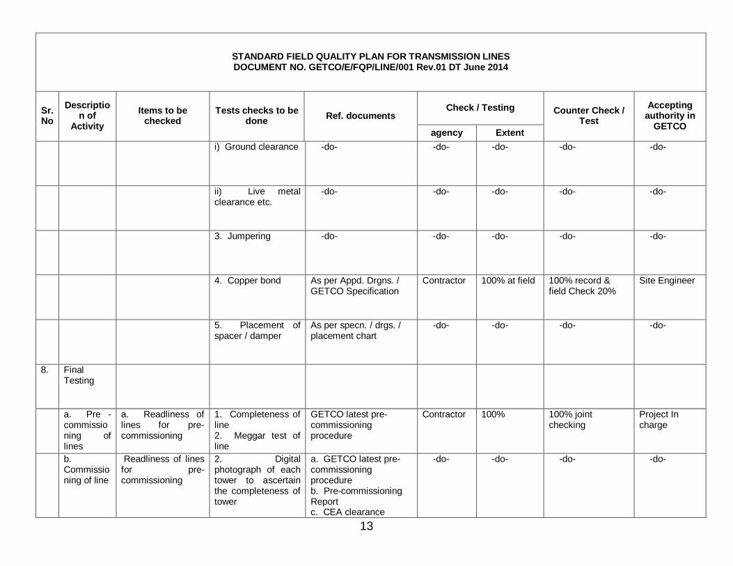
i) Ground clearance -do- -do- -do- -do- -do-
ii) Live metal clearance etc.
-do- -do- -do- -do- -do-
3. Jumpering -do- -do- -do- -do- -do-
4. Copper bond As per Appd. Drgns. / GETCO Specification
Contractor 100% at field 100% record & field Check 20%
Site Engineer
5. Placement of spacer / damper
As per specn. / drgs. / placement chart
-do- -do- -do- -do-
8. Final Testing
a. Pre - commissioning of lines
a. Readliness of lines for pre-commissioning
1. Completeness of line 2. Meggar test of line
GETCO latest pre-commissioning procedure
Contractor 100% 100% joint checking
Project In charge
b. Commissioning of line
Readliness of lines for pre-commissioning
2. Digital photograph of each tower to ascertain the completeness of tower
a. GETCO latest pre-commissioning procedure b. Pre-commissioning Report c. CEA clearance
-do- -do- -do- -do-
14
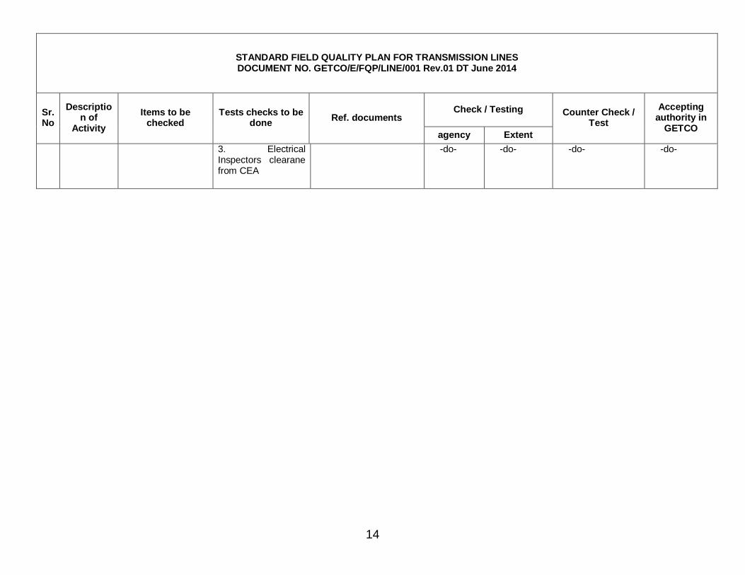
STANDARD FIELD QUALITY PLAN FOR TRANSMISSION LINES DOCUMENT NO. GETCO/E/FQP/LINE/001 Rev.01 DT June 2014
Check / Testing Sr. No
Description of
Activity Items to be
checked Tests checks to be
done Ref. documents
agency Extent
Counter Check / Test
Accepting authority in
GETCO
3. Electrical Inspectors clearane from CEA
-do- -do- -do- -do-

15
Annexure - 1
ORDINARY PORTLAND CEMENT
Sr. No.
Name of the test Ordinary Portland Cement 33 grade as per IS 269
Ordinary Portland Cement 43 grade as per IS 6112
Ordinary Portland Cement 53 grade as per IS 122269
Remarks
1. a) Physical tests To be conducted in apprd.
Lab. (i) Fineness Specific surface area shall
not be less than 225 sq. m. per Kg. or 2250 Cm2/gm.
Specific surface area shall not be less tan 225 sq. m. per Kg or 2250 Cm2/gm.
Specific surface area shall not be less tan 225 sq. m. per Kg or 2250 Cm2/gm.
Blaine's air permeability method as per IS 4031 (Part-2)
(ii) Compressive strength 72+/- 1 hour: Not less than 16 Mpa (16 N/mm2)
72+/- 1 hour: Not less than 23 Mpa (23 N/mm2)
72+/- 1 hour: Not less than 27 Mpa (16 N/mm2)
As per IS 4031 (Part-6)
168+/- 2 hour: Not less than 22 Mpa (22 N/mm2)
168+/- 2 hour: Not less than 33 Mpa (33 N/mm2)
168+/- 2 hour: Not less than 37 Mpa (37 N/mm2)
672+/- 4 hour: Not less than 33 Mpa (33 N/mm2)
672+/- 4 hour: Not less than 43 Mpa (43 N/mm2)
672+/- 4 hour: Not less than 53 Mpa (53 N/mm2)
(iii) Initial & Final setting time Initial setting time : Not less than 30 minutes
Initial setting time : Not less than 30 minutes
Initial setting time : Not less than 30 minutes
As per IS 4031 (Part-5)
Final setting time : Not more than 600 minutes
Final setting time : Not more than 600 minutes
Final setting time : Not more than 600 minutes
-do-
(iv) Soundness Unaerated cement shall not have an expansion of more than 10mm when tested by Le chatlier and 0.8% Autoclave test.
Unaerated cement shall not have an expansion of more than 10mm when tested by Le chatlier and 0.8% Autoclave test.
Unaerated cement shall not have an expansion of more than 10mm when tested by Le chatlier and 0.8% Autoclave test.
Le chatlier and Autoclave test as per IS 4031 (Part-3)
b Chemical composition tests Ratio of percentage of lime to
percentage of silica, alumina & iron oxide 0.66 to 1.02
Ratio of percentage of lime to percentage of silica, alumina & iron oxide 0.66 to 1.02
Ratio of percentage of lime to percentage of silica, alumina & iron oxide 0.66 to 1.02
Ratio of percentage of alumina to that of iron oxide Minimum 0.66%
Ratio of percentage of alumina to that of iron oxide Minimum 0.66%
Ratio of percentage of alumina to that of iron oxide Minimum 0.66%
Insoluble residue, percentage by mass Max. 4.00%
Insoluble residue, percentage by mass Max. 4.00%
Insoluble residue, percentage by mass Max. 4.00%
Magnesia percentage by mass Max. 6%
Magnesia percentage by mass Max. 6%
Magnesia percentage by mass Max. 6%
Total sulphur content calculated as sulphuric
Total sulphur content calculated as sulphuric
Total sulphur content calculated as sulphuric
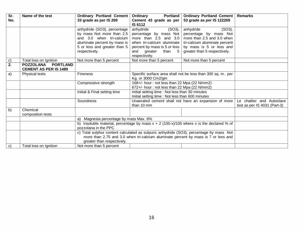
16
Sr. No.
Name of the test Ordinary Portland Cement 33 grade as per IS 269
Ordinary Portland Cement 43 grade as per IS 6112
Ordinary Portland Cement 53 grade as per IS 122269
Remarks
anhydride (SO3), percentage by mass Not more than 2.5 and 3.0 when tri-calcium aluminate percent by mass is 5 or less and greater than 5 respectively.
anhydride (SO3), percentage by mass Not more than 2.5 and 3.0 when tri-calcium aluminate percent by mass is 5 or less and greater than 5 respectively.
anhydride (SO3), percentage by mass Not more than 2.5 and 3.0 when tri-calcium aluminate percent by mass is 5 or less and greater than 5 respectively.
c) Total loss on Ignition Not more than 5 percent Not more than 5 percent Not more than 5 percent 2. POZZOLANA PORTLAND
CEMENT AS PER IS 1489
a) Physical tests Fineness Specific surface area shall not be less than 300 sq. m.. per Kg. or 3000 Cm2/gm
Compressive strength 168+/- hour : not less than 22 Mpa (22 N/mm2) 672+/- hour : not less than 22 Mpa (22 N/mm2)
Initial & Final setting time Initial setting time : Not less than 30 minutes Initial setting time : Not less than 600 minutes
Soundness Unaerated cement shall not have an expansion of more than 10 mm
Le chatlier and Autoclave test as per IS 4031 (Part-3)
b) Chemical composition tests
a) Magnesia percentage by mass Max. 6% b) Insoluble material, percentage by mass x + 2 (100-x)/100 where x is the declared % of
pozzolana in the PPC
c) Total sulphur content calculated as sulpuric anhydride (SO3), percentage by mass Not more than 2.75 and 3.0 when tri-calcium aluminate percent by mass is 7 or less and greater than respectively.
c) Total loss on Ignition Not more than 5 percent
17
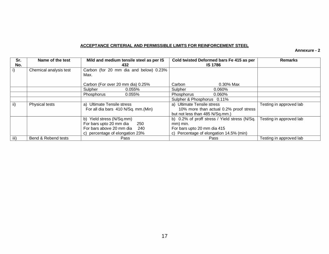
ACCEPTANCE CRITERIAL AND PERMISSIBLE LIMITS FOR REINFORCEMENT STEEL Annexure - 2
Sr. No.
Name of the test Mild and medium tensile steel as per IS 432
Cold twisted Deformed bars Fe 415 as per IS 1786
Remarks
i) Chemical analysis test Carbon (for 20 mm dia and below) 0.23% Max. Carbon (For over 20 mm dia) 0.25%
Carbon 0.30% Max
Sulpher 0.055% Sulpher 0.060% Phosphorus 0.055% Phosphorus 0.060% Sulpher & Phosphorus 0.11% ii) Physical tests a) Ultimate Tensile stress
For all dia bars 410 N/Sq. mm.(Min) a) Ultimate Tensile stress 10% more than actual 0.2% proof stress but not less than 485 N/Sq.mm.)
Testing in approved lab
b) Yield stress (N/Sq.mm) For bars upto 20 mm dia 250 For bars above 20 mm dia 240 c) percentage of elongation 23%
b) 0.2% of proff stress / Yield stress (N/Sq. mm) min. For bars upto 20 mm dia 415 c) Percentage of elongation 14.5% (min)
Testing in approved lab
iii) Bend & Rebend tests Pass Pass Testing in approved lab
18
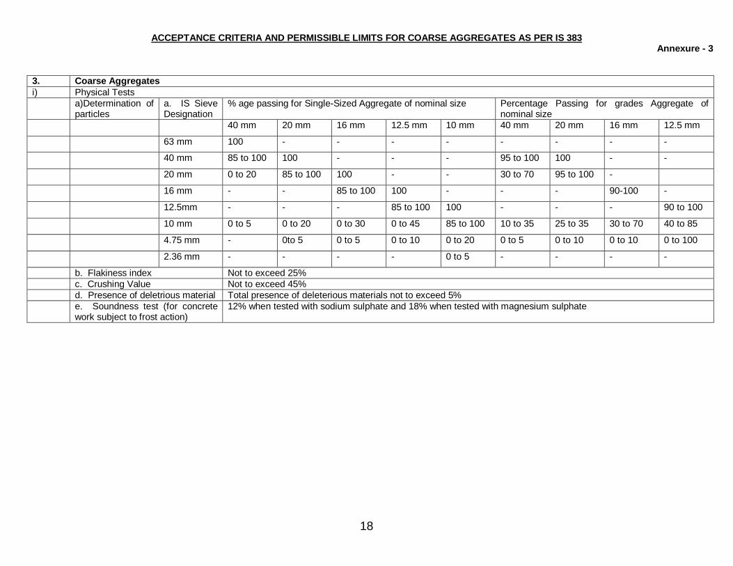
ACCEPTANCE CRITERIA AND PERMISSIBLE LIMITS FOR COARSE AGGREGATES AS PER IS 383 Annexure - 3
3. Coarse Aggregates i) Physical Tests a)Determination of
particles a. IS Sieve Designation
% age passing for Single-Sized Aggregate of nominal size Percentage Passing for grades Aggregate of nominal size
40 mm 20 mm 16 mm 12.5 mm 10 mm 40 mm 20 mm 16 mm 12.5 mm
63 mm 100 - - - - - - - -
40 mm 85 to 100 100 - - - 95 to 100 100 - -
20 mm 0 to 20 85 to 100 100 - - 30 to 70 95 to 100 -
16 mm - - 85 to 100 100 - - - 90-100 -
12.5mm - - - 85 to 100 100 - - - 90 to 100
10 mm 0 to 5 0 to 20 0 to 30 0 to 45 85 to 100 10 to 35 25 to 35 30 to 70 40 to 85
4.75 mm - 0to 5 0 to 5 0 to 10 0 to 20 0 to 5 0 to 10 0 to 10 0 to 100
2.36 mm - - - - 0 to 5 - - - -
b. Flakiness index Not to exceed 25% c. Crushing Value Not to exceed 45% d. Presence of deletrious material Total presence of deleterious materials not to exceed 5% e. Soundness test (for concrete
work subject to frost action) 12% when tested with sodium sulphate and 18% when tested with magnesium sulphate
19
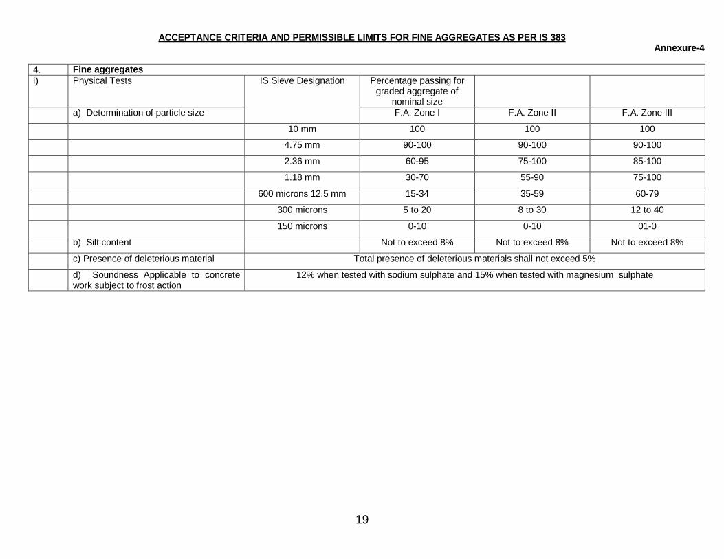
ACCEPTANCE CRITERIA AND PERMISSIBLE LIMITS FOR FINE AGGREGATES AS PER IS 383 Annexure-4
4. Fine aggregates i) Physical Tests Percentage passing for
graded aggregate of nominal size
a) Determination of particle size
IS Sieve Designation
F.A. Zone I F.A. Zone II F.A. Zone III
10 mm 100 100 100
4.75 mm 90-100 90-100 90-100
2.36 mm 60-95 75-100 85-100
1.18 mm 30-70 55-90 75-100
600 microns 12.5 mm 15-34 35-59 60-79
300 microns 5 to 20 8 to 30 12 to 40
150 microns 0-10 0-10 01-0
b) Silt content Not to exceed 8% Not to exceed 8% Not to exceed 8%
c) Presence of deleterious material Total presence of deleterious materials shall not exceed 5%
d) Soundness Applicable to concrete work subject to frost action
12% when tested with sodium sulphate and 15% when tested with magnesium sulphate

20
ACCEPTANCE CRITERIA AND PERMISSIBLE LIMITS FOR CONCRETE WORK Annexure-5
1) Concrete a) Workability Slump shall be recorded by slump cone method and it shall between 25-55 b) Compressive strength Three samples of 15 cm cube for 28 days compressive strength for all concrete
works except pile foundation work shall be taken. For pile foundation works, six cubes, three for 7 days testing and balance three for 28 days testing shall be taken.
Notes: 1. For nominal (Volumetric concrete mixes, compressive strength for 1:1.5:3 (Sand: fine aggregates: Coarse aggregates) concrete shall be 265 kg/Sq.cm. for
28 days and for 1:2:4 nominal mix, it shall be 210 kg/Sq.cm. 2. ACCEPTANCE CRITERIA BASED ON 28 DAYS COMPRESSIVE STRENGTHS FOR NOMINAL MIX CONCRETE: a) The average of the strength of three specimen be accepted as the compressive strength of the concrete, provided the strength of any individual cube shall
neither be less than 70% nor higher than 130% of the specified strength. b) If the actual average strength of accepted sample exceeds specified strength by more than 30%, the Engineer-in charge, if he so desires, may further
investigate the matter. However, if the strength of any individual cube exceeds more than 30% of the specified strength, it will be restructed to 30% only for computation of strength.
c) If the actual average strength of accepted sample is equal to or higher than specified upto 30%, the strength of the concrete shall be considered in order and the concrete shall be accepted at full rates.
d) If the actual average strength of accepted sample is less than specified strength but not less than 70% of the specified strength, concrete may be accepted at reduced rate at the discretion of Engineer-in-charge.
e) If the actual average strength of accepted sample is less than 70% of specified strength, the Engineer-in-charge shall reject the defective portion of work represent by sample and nothing shall be paid for the rejected work. Remedial measures necessary to retain the structure shall taken at the risk and cost of contractor. If, however, the Engineer-in-charge so desires, he may order additional tests to be carried out to ascertain if the structure can be retained. All the charges in connection with these additional tests shall be borne by the contractor.
General 1) This standard Field Quality Plan is not to limit the supervisory checks which are otherwise required to be carried out during execution of work as per
drawings / Technical specifications etc. 2) All materials / Equipments should be purchased from GETCO's approved Vendors only. 3) Contractors shall be responsible for implementing / documenting the FQP. Documents shall be handed over by the contractor to GETCO after the
completion of the work. 4) Projection in charge means over all in charge of work. Line in charge mean in charge of the line. Section in-charge means incharge of the section. 5) In case of deviation the approving authority will be one step above the officer designated for acceptance in this quality plan subject to minimum level
of Lien in charge. 6) Acceptance criteria and permissible limits for tests are indicated in the Annexures. However for further details / tests GETCO specification and
relevant Indian standards shall be referred. 7) Tests as mentioned in this FQP shall generally be followed. However, E.I.C,. reserves the right to order additional tests wherever required
necessary at the cost of the agency.. 8) All counter checks / tests by GETCO shall be carried out by GETCO's officials atleast at the level of Jr.Engr.
21
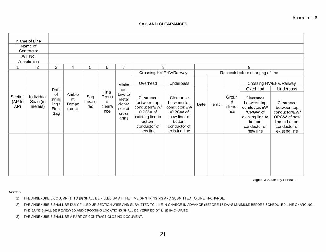
Annexure – 6 SAG AND CLEARANCES
Name of Line Name of
Contractor A/T No.
Jurisdiction 1 2 3 4 5 6 7 8 9
Crossing HV/EHV/Railway Recheck before charging of line
Overhead Underpass Crossing HV/EHV/Railway Overhead Underpass
Section (AP to AP)
Individual Span (in meters)
Date of
stringing / Final Sag
Ambient
Temperature
Sag measu
red
Final Groun
d clearance
Minimum
Live to metal clearance at cross arms
Clearance between top
conductor/EW/OPGW of
existing line to bottom
conductor of new line
Clearance between top
conductor/EW/OPGW of new line to
bottom conductor of existing line
Date Temp.
Ground
clearance
Clearance between top
conductor/EW/OPGW of
existing line to bottom
conductor of new line
Clearance between top
conductor/EW/OPGW of new line to bottom conductor of existing line
Signed & Sealed by Contractor
NOTE :-
1) THE ANNEXURE-6 COLUMN (1) TO (8) SHALL BE FILLED UP AT THE TIME OF STRINGING AND SUBMITTED TO LINE IN-CHARGE.
2) THE ANNEXURE-6 SHALL BE DULY FILLED UP SECTION WISE AND SUBMITTED TO LINE IN-CHARGE IN ADVANCE (BEFORE 15 DAYS MINIMUM) BEFORE SCHEDULED LINE CHARGING.
THE SAME SHALL BE REVIEWED AND CROSSING LOCATIONS SHALL BE VERIFIED BY LINE IN-CHARGE.
3) THE ANNEXURE-6 SHALL BE A PART OF CONTRACT CLOSING DOCUMENT.
22
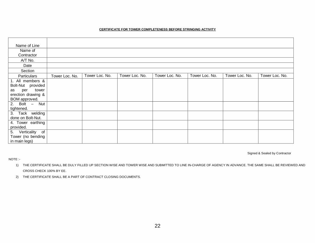
CERTIFICATE FOR TOWER COMPLETENESS BEFORE STRINGING ACTIVITY
Name of Line Name of
Contractor A/T No.
Date Section
Particulars Tower Loc. No. Tower Loc. No. Tower Loc. No. Tower Loc. No. Tower Loc. No. Tower Loc. No. Tower Loc. No. 1. All members & Bolt-Nut provided as per tower erection drawing & BOM approved. 2. Bolt – Nut tightened. 3. Tack welding done on Bolt-Nut. 4. Tower earthing provided. 5. Verticality of Tower (no bending in main legs)
Signed & Sealed by Contractor
NOTE :-
1) THE CERTIFICATE SHALL BE DULY FILLED UP SECTION WISE AND TOWER WISE AND SUBMITTED TO LINE IN-CHARGE OF AGENCY IN ADVANCE. THE SAME SHALL BE REVIEWED AND
CROSS CHECK 100% BY EE.
2) THE CERTIFICATE SHALL BE A PART OF CONTRACT CLOSING DOCUMENTS.