gujarat energy transmission … office/2013/190913/a/3_ts...gujarat energy transmission corporation...
TRANSCRIPT
GETCO / E / TS – CRP 3601 / R5 Dt. 07.05.13
Seal & Sign of Bidder Page 1 of 109
GUJARAT ENERGY TRANSMISSION
CORPORATION LTD.
SARADAR PATEL VIDYUT BHAVAN,
RACE COURSE, BARODA – 390 007.
TECHNICAL SPECIFICATION
FOR
400/220/132 KV CONTROL & RELAY PANELS
GETCO / E / TS – CRP 3601 / R5 Dt. 07.05.13
GETCO / E / TS – CRP 3601 / R5 Dt. 07.05.13
Seal & Sign of Bidder Page 2 of 109
SECTION: I
QUALIFYING REQUIREMENT FOR BIDDERS FOR C & R PANELS
1. The bidder shall be original Relay manufacturer for 220 & 400KV class. The offered
Relay / C&R Panels have to be designed, manufactured and tested as per relevant IS/IEC with latest amendments.
1.A Bidders not meeting the requirements at 1 above but authorized by OEM having
qualifying requirement as per 1 above can also participate for 132KV class only, provided they have valid ongoing collaboration with manufacturer. In such an event the bidder shall furnish, along with his bid, documentary evidence for the same and an undertaking from the bidder and collaborator accepting joint and several liabilities of all the obligations under the contract.
2. The minimum requirement of manufacturing capacity of offered type, size and rating of
Relays / C&R panels shall be as per Annexure-A. The bidder should indicate manufacturing capacity by submitting latest updated certificate of a Chartered Engineer (CE).
3. Relay / C&R panel offered shall be of similar or higher rating and in service for a
minimum period of THREE (3) years and satisfactory performance certificate from utilities like SEB’s, NTPC, PGCIL etc. in respect of this should be submitted. Also the name of the authority, contact and fax no. and email address, from whom the reference can be made, shall be given.
4. The bidder should clearly indicate the quantity and single value contract executed
during last five (5) years for the offered product. Bidder should have executed one single contract during last five years for the quantity equivalent to tender / bid. The details should be submitted as per following format.
Sr.
No.
ITEMS
SUPPLIED
TO
ORDER
REFERENCE
NO. & DATE
ITEMS QUANTITY ORDER
FULLY
EXECUTED
YES/NO
STATUS
IF ORDER
UNDER
EXECUTION
REMARKS
5. Relay / C&R panel offered shall have type test certificates from accredited laboratory
(accreditation based on ISO/IEC/Guide 25/17025 or EN 45001 by the national accreditation body of the country where the lab is located.) as per IS/IEC/Technical specification, not older than FIVE (5) years from the expiry date of validity of offer.
6. The bidder shall guarantee for supplying maintenance spares and services as well as
repairing of relays for a period of the life expectancy of 25 years.

GETCO / E / TS – CRP 3601 / R5 Dt. 07.05.13
Seal & Sign of Bidder Page 3 of 109
ANNEXURE - A Sr. No.
Product Annual manufacturing capacity (In multiple of tender / bid quantity)_
1 Relays 5
2 C&R Panels 5
GETCO / E / TS – CRP 3601 / R5 Dt. 07.05.13
Seal & Sign of Bidder Page 4 of 109
SECTION –I I
SPECIFICATION FOR 400/220/132 KV SYSTEM CONTROL AND RELAY PANELS
1.0 SCOPE 1.1 The overall scope of work proposed to be assigned to the successful bidder
according to this specification covers the following aspects. 1.1.1 The design, preparation of schematic and drawings, manufacture, testing at
manufacturer’s works, mounting and wiring up of all the equipment as detailed in the equipment schedule-G of 400/220/132KV control and relay panels F.O.R destination supply thereof, testing and commissioning at site.
1.1.2 Design and manufacture of relay and relay assemblies to meet the
requirements of various protection schemes for protection of
a) 400/220/132KV feeders b) 400/220, 220/11KV, 220/66KV, 220/132KV Auto/Two winding
transformers c) 400/220/132KV Bus coupler d) 400/220/132KV Transfer bus coupler e) 400/220KV Reactor
1.1.2.1 Design and fabrication of relay panels for mounting the relay and relay
assemblies along with all necessary accessories like switches, indicating lamps etc. and wiring up of the same to provide self contained and ready to use protection as per this specification.
1.1.3 Complete testing at manufacturer’s works of the relays and protection
schemes after mounting and fully wiring up in the relay panels. 1.1.4 F.O.R. destination supply of completely assembled control and relay panels. 1.1.5 Testing and commissioning of these panels at site. 1.1.6 It is not the intent to specify completely all the details of the design and
construction of equipment. However, the equipment shall conform in all respects to high standards of engineering, design and workmanship as mentioned in clause 4.0 and shall be capable of performing continuous commercial operation up to the supplier’s guarantee. In a manner acceptable to the purchaser, who will interpret the meaning of drawings and specifications, and shall have the power to reject any work of material which, in his judgment is not in accordance therewith. The offered equipment shall be complete with all components necessary for their effective trouble free operation. Such components shall be deemed to whether those are specifically brought out in this specification and/or the commercial order or not.
GETCO / E / TS – CRP 3601 / R5 Dt. 07.05.13
Seal & Sign of Bidder Page 5 of 109
2.0 SCHEDULE OF REQUIREMENT 2.1 The requirement of control and relay panels to be supplied against this
specification and their required deliveries are given in Commercial Terms and Conditions.
2.2 The delivery instructions shall be issued to the successful bidder/s after
placement of orders and after inspection and testing of panels at manufacturer’s works.
2.3 Recommended spares The bidder shall furnish in his offer, a list of recommended spare with unit
rates for control and relay panel that may be required for trouble free operation for a period of 10 years. The purchaser reserves the right of selection of items and quantities of these spares to be ordered. The bidder is bound to supply spares for maintenance as and when required for service life of the protections as per clause No.17.0.
2.4 Recommended tools, testing kits, test handles etc. The bidder shall furnish in his offer a list of recommended testing kit,
tools and test handle with unit rates for control & relay panels those may be required during testing and commissioning of said panel, off line as well as on line testing as per Ann. IX. The purchaser reserves the right of selection of items and quantities to be ordered.
2.5. Bidders are required to quote the service engineer charges as per clause
no.13.0 3. STANDARDS: 3.1. Unless otherwise specified elsewhere, in this specification, the rating,
performance and testing of control and relay panels and accessories shall conform to the latest revisions, available at the time of placement of order of all relevant standards listed in Annexure – II. Copies of Indian Standards specifications can be obtained from Bureau of Indian Standards, Manak Bhavan, Bahadurshah Jafar Mar, New Delhi : 110 002 on payment of application charges.
However the supplier shall submit the copies of the relevant standards applicable to the 400/220/132KV C&R Panel.
3.2. The equipment shall also comply the latest revision of Indian Electricity Act
and Indian Electricity Rules and any other applicable statutory provisions, rules and regulations applicable in the locations where these are to be installed.
.
GETCO / E / TS – CRP 3601 / R5 Dt. 07.05.13
Seal & Sign of Bidder Page 6 of 109
4. PRINCIPAL TECHNICAL PARAMETERS:
The control & relay panel covered in these specifications shall have the technical requirements listed in Annexure – III.
5. GENERAL TECHNICAL REQUIREMENTS: 5.1. SCOPE OF WORK. 5.1.1. Design and fabrication of complete panels with provision for mounting all
the associated equipment. The list of major mountings shall be given in Schedule – G.
5.1.2. Supply and mounting of all equipment as specified in schedule `G’ and in
this specification together with such auxiliary equipment and materials as required. The bidder shall indicate make, type and designation of all equipments in the bid.
5.1.3. Complete internal wiring of equipment and terminal blocks and wiring
between adjacent panels. Design and manufacture of relays and relay assemblies to meet the requirement of various protection schemes, specified hereunder for the panels as per Annexure – I.
5.1.4. Electrical detailing as outlined in this specification.
5.1.5. Preparation and furnishing of all the required drawings including schematic,
internal external cable connection drawings and wiring schedules. All wires shall be ferruled at both ends even on shorting links also and shall be clearly shown in the schematic drawings.
5.1.6. Testing of panels and associated equipments and furnishing of test
certificates.
5.1.7. Preparation and furnishing of erection, commissioning instructions, operation and maintenance manuals for all protections with all operational features/optional features.
5.1.8. Testing and commissioning of all the supplied equipment at site.
5.1.9. The successful tenders have to submit seven sets of all types of drawings,
schematics and electrical internal circuits, indicating measuring points and measuring values, external cable connection drawings, wiring schedules, erection instructions, operation and maintenance manuals.
5.1.10. DETAILS OF INSTRUMENT TRANSFORMRS AND POWER
TRANSFORMRS (ICT)

GETCO / E / TS – CRP 3601 / R5 Dt. 07.05.13
Seal & Sign of Bidder Page 7 of 109
5.1.10.1. 400KV CURRENT TRANSFORMERS HAVING 1 AMP SECONDARY.
Sr No.
Parameter Core - I Core - II Core - III Core - IV Core - V
1 Ratio 2000-1000-500/
1 A 1 A 1 A 1 A 1 A
2 Rated Burden --- --- 40 --- --- 3 Class of
Accuracy PS PS 0.5 PS PS
4 Accuracy Limit Factor
--- --- ISF < 5 --- ---
5 Min KPV (Vk) 4000 at 2000/1
4000 at 2000/1
--- 2000 at 2000/1
2000 at 2000/1
6 Max Iex at Vk 30 on 2000/1,60
on 1000/1, 120 on 500/1
30 on 2000/1,60
on 1000/1, 120 on 500/1
--- 30 on 2000/1,60
on 1000/1, 120 on 500/1
30 on 2000/1,60
on 1000/1, 120 on 500/1
7 Rsec (Ω) 10/5/2.5 10/5/2.5 10/5/2.5 10/5/2.5 10/5/2.5 8 Purpose Trf / Line
Main - 1 Trf / Line Main - 2
Metering Bus Bar Protection
Bus Bar Protection
220/132KV CURRENT TRANSFORMERS HAVING 1 AMP SECONDARY
Sr No.
Parameter Core - I Core - II Core - III Core - IV Core - V
1 Ratio 1200-600-300/
1 A 1 A 1 A 1 A 1 A
2 Rated Burden 30 30 --- --- --- 3 Class of
Accuracy 0.5 5P20 PS PS PS
4 Accuracy Limit Factor
ISF < 5 --- --- --- ---
5 Min KPV (Vk) --- --- 1400 at 1200/1
1400 at 1200/1
1400 at 1200/1
6 Max Iex at Vk --- --- 25 25 25 7 Rsec (Ω) --- --- < 12 < 12 < 12 8 Purpose Instru-
mentation Back-up Protection
Main – I Protection
Main – II Protection
Bus Bar Protection
Nos. of CT cores are typical. However for 400kv and 220kv class it may be 4 nos. / 5 nos. for new /existing substation as per requirement. For 132kv system, it may be 3 nos. / 4 nos. / 5 nos. as per requirement.
GETCO / E / TS – CRP 3601 / R5 Dt. 07.05.13
Seal & Sign of Bidder Page 8 of 109
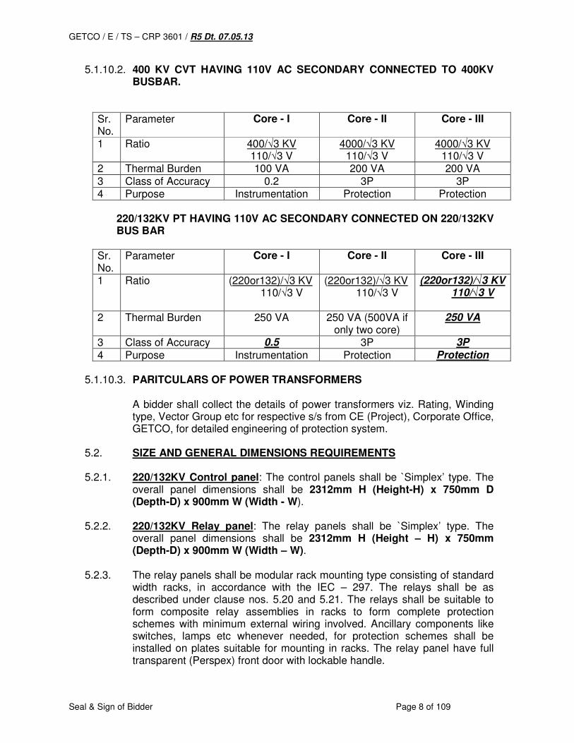
5.1.10.2. 400 KV CVT HAVING 110V AC SECONDARY CONNECTED TO 400KV BUSBAR.
Sr. No.
Parameter Core - I Core - II Core - III
1 Ratio 400/√3 KV 110/√3 V
4000/√3 KV 110/√3 V
4000/√3 KV 110/√3 V
2 Thermal Burden 100 VA 200 VA 200 VA 3 Class of Accuracy 0.2 3P 3P 4 Purpose Instrumentation Protection Protection
220/132KV PT HAVING 110V AC SECONDARY CONNECTED ON 220/132KV
BUS BAR
Sr. No.
Parameter Core - I Core - II Core - III
1 Ratio (220or132)/√3 KV 110/√3 V
(220or132)/√3 KV 110/√3 V
(220or132)/√3 KV 110/√3 V
2 Thermal Burden 250 VA 250 VA (500VA if only two core)
250 VA
3 Class of Accuracy 0.5 3P 3P
4 Purpose Instrumentation Protection Protection
5.1.10.3. PARITCULARS OF POWER TRANSFORMERS
A bidder shall collect the details of power transformers viz. Rating, Winding type, Vector Group etc for respective s/s from CE (Project), Corporate Office, GETCO, for detailed engineering of protection system.
5.2. SIZE AND GENERAL DIMENSIONS REQUIREMENTS 5.2.1. 220/132KV Control panel: The control panels shall be `Simplex’ type. The
overall panel dimensions shall be 2312mm H (Height-H) x 750mm D (Depth-D) x 900mm W (Width - W).
5.2.2. 220/132KV Relay panel: The relay panels shall be `Simplex’ type. The
overall panel dimensions shall be 2312mm H (Height – H) x 750mm (Depth-D) x 900mm W (Width – W).
5.2.3. The relay panels shall be modular rack mounting type consisting of standard
width racks, in accordance with the IEC – 297. The relays shall be as described under clause nos. 5.20 and 5.21. The relays shall be suitable to form composite relay assemblies in racks to form complete protection schemes with minimum external wiring involved. Ancillary components like switches, lamps etc whenever needed, for protection schemes shall be installed on plates suitable for mounting in racks. The relay panel have full transparent (Perspex) front door with lockable handle.
GETCO / E / TS – CRP 3601 / R5 Dt. 07.05.13
Seal & Sign of Bidder Page 9 of 109
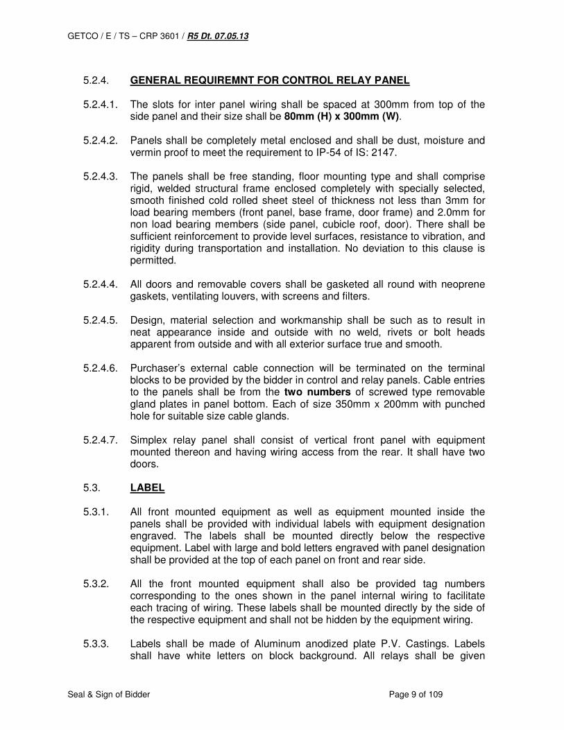
5.2.4. GENERAL REQUIREMNT FOR CONTROL RELAY PANEL
5.2.4.1. The slots for inter panel wiring shall be spaced at 300mm from top of the
side panel and their size shall be 80mm (H) x 300mm (W). 5.2.4.2. Panels shall be completely metal enclosed and shall be dust, moisture and
vermin proof to meet the requirement to IP-54 of IS: 2147.
5.2.4.3. The panels shall be free standing, floor mounting type and shall comprise rigid, welded structural frame enclosed completely with specially selected, smooth finished cold rolled sheet steel of thickness not less than 3mm for load bearing members (front panel, base frame, door frame) and 2.0mm for non load bearing members (side panel, cubicle roof, door). There shall be sufficient reinforcement to provide level surfaces, resistance to vibration, and rigidity during transportation and installation. No deviation to this clause is permitted.
5.2.4.4. All doors and removable covers shall be gasketed all round with neoprene
gaskets, ventilating louvers, with screens and filters.
5.2.4.5. Design, material selection and workmanship shall be such as to result in neat appearance inside and outside with no weld, rivets or bolt heads apparent from outside and with all exterior surface true and smooth.
5.2.4.6. Purchaser’s external cable connection will be terminated on the terminal
blocks to be provided by the bidder in control and relay panels. Cable entries to the panels shall be from the two numbers of screwed type removable gland plates in panel bottom. Each of size 350mm x 200mm with punched hole for suitable size cable glands.
5.2.4.7. Simplex relay panel shall consist of vertical front panel with equipment
mounted thereon and having wiring access from the rear. It shall have two doors.
5.3. LABEL 5.3.1. All front mounted equipment as well as equipment mounted inside the
panels shall be provided with individual labels with equipment designation engraved. The labels shall be mounted directly below the respective equipment. Label with large and bold letters engraved with panel designation shall be provided at the top of each panel on front and rear side.
5.3.2. All the front mounted equipment shall also be provided tag numbers
corresponding to the ones shown in the panel internal wiring to facilitate each tracing of wiring. These labels shall be mounted directly by the side of the respective equipment and shall not be hidden by the equipment wiring.
5.3.3. Labels shall be made of Aluminum anodized plate P.V. Castings. Labels
shall have white letters on block background. All relays shall be given
GETCO / E / TS – CRP 3601 / R5 Dt. 07.05.13
Seal & Sign of Bidder Page 10 of 109
standard abbreviation numbers with name of device, corresponding to the ones shown in the panel internal wiring.
5.3.4. Each instrument and meter shall be prominently marked with the quantity
measured e.g. KV, A, MW etc.
5.3.5. Each switch shall bear clear inspection identifying its function e.g. `BREAKER’, 52A, `SYNCHRONISING’ etc. Similar inscription shall also be provided on each device whose function is not otherwise identified. If any switch device does not bear this inscription separate nameplate giving its function shall be provided for it. Switch shall also have clear inscription for each position indication e.g. `Trip – Neutral – Close’, `ON-OFF’, `R-Y-B-OFF’ etc.
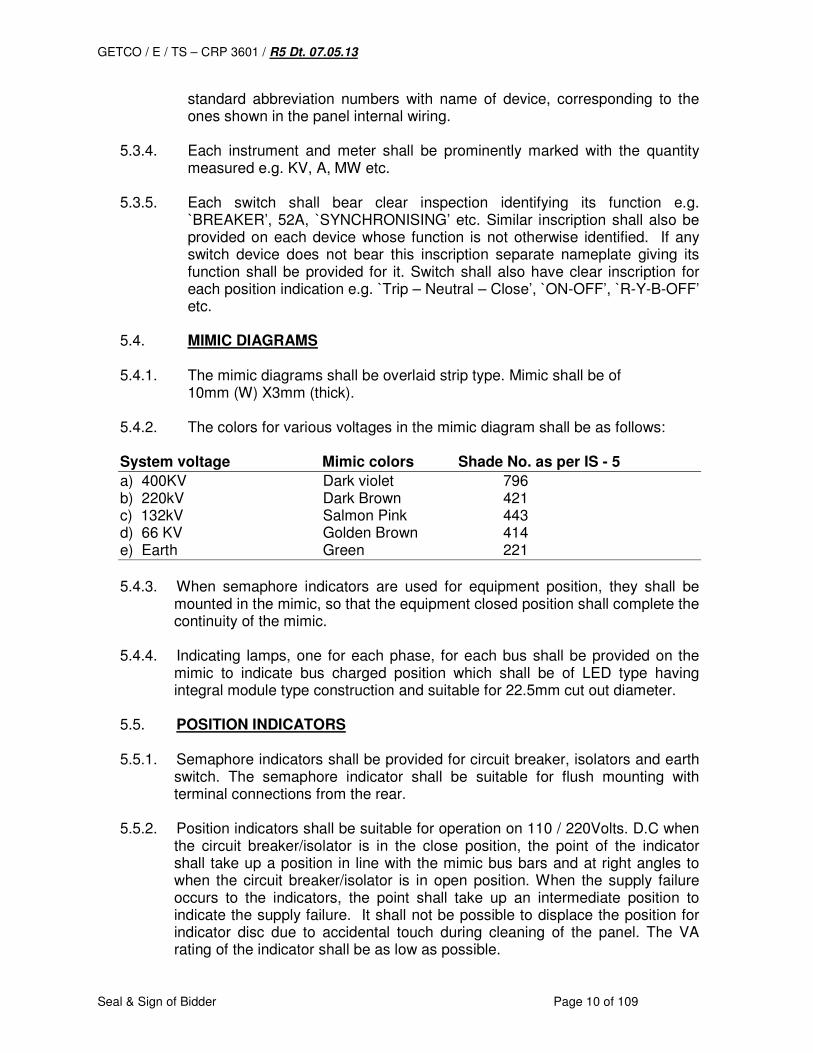
5.4. MIMIC DIAGRAMS 5.4.1. The mimic diagrams shall be overlaid strip type. Mimic shall be of 10mm (W) X3mm (thick). 5.4.2. The colors for various voltages in the mimic diagram shall be as follows: System voltage Mimic colors Shade No. as per IS - 5
a) 400KV Dark violet 796 b) 220kV Dark Brown 421 c) 132kV Salmon Pink 443 d) 66 KV Golden Brown 414 e) Earth Green 221
5.4.3. When semaphore indicators are used for equipment position, they shall be
mounted in the mimic, so that the equipment closed position shall complete the continuity of the mimic.
5.4.4. Indicating lamps, one for each phase, for each bus shall be provided on the
mimic to indicate bus charged position which shall be of LED type having integral module type construction and suitable for 22.5mm cut out diameter.
5.5. POSITION INDICATORS 5.5.1. Semaphore indicators shall be provided for circuit breaker, isolators and earth
switch. The semaphore indicator shall be suitable for flush mounting with terminal connections from the rear.
5.5.2. Position indicators shall be suitable for operation on 110 / 220Volts. D.C when
the circuit breaker/isolator is in the close position, the point of the indicator shall take up a position in line with the mimic bus bars and at right angles to when the circuit breaker/isolator is in open position. When the supply failure occurs to the indicators, the point shall take up an intermediate position to indicate the supply failure. It shall not be possible to displace the position for indicator disc due to accidental touch during cleaning of the panel. The VA rating of the indicator shall be as low as possible.
GETCO / E / TS – CRP 3601 / R5 Dt. 07.05.13
Seal & Sign of Bidder Page 11 of 109
5.6. CONTROL SWITCHES 5.6.1. Control and Instrument switch shall be rotary type provided with escutcheon
plates clearly marked to show operating position and suitable for flush mounting with only the switch front plate and operating handle projecting out. The connections shall be from the rear. The contact assembly at the back of the switch shall be enclosed in dust tight removable covers. The access to the contacts shall be from the back by the removal of the cover. Contact assembly shall be smooth enough for operations.
5.6.2. Isolator/breaker control switch of “3 position spring return to neutral” type shall
be provided. The control springs shall be strong and robust enough to prevent inadvertent operation due to light touch. The spring return type switch shall have spring return from close and trip position to `After Close’ and `After Trip’ positions respectively. The handle for breaker control switch shall have RED COLOUR.
5.6.3. Contacts of the switch shall be spring assisted and contact faces shall be
silver plated. Spring shall not be used as current carrying parts. The contacts of all switches shall preferably open and close with snap action to minimize arcing. The contact rating of the switches shall be as follows:
Description Contact rating in Amps.
240V 110VAC 220VDC a) Make and carry continuously 10A 10A 10A b) Make and carry for 0.5 sec. 30A 30A 30A
c) Break 1) Resistive load 2) Inductive load
with L/R = 40msec.
7A 7A
7A 5A
3A 2A
5.6.4. Trip transfer switch shall have 3 positions Normal/Intermediate/Transfer. All
transfer switches shall have a common key which can be removed in normal position only to prevent operation more than one switch being in transfer position simultaneously. It shall be ensured that during transfer when two breakers in parallel are controlling the circuit, faults in circuits are successfully cleared. On transfer position, trip circuits of main C.B. shall be isolated and tripping of TBC only shall be extended on operation of protection or on manual operation.
5.6.5. Lockable type of switches which can be locked in particular positions shall be
provided when specified. The key locks shall be fitted on the operating handles. Make, type of the switch shall be suggested by Bidder.
5.6.6. Synchronizing switch shall be of maintained contact (stay put) type having a
common key for group of switches. The key shall be removable only in the OFF position. These switches shall be arranged to connect the synchronizing equipment when turned to the `On’ position. One contact of each switch shall be connected in the closing circuit of the respective breaker so that the breaker
GETCO / E / TS – CRP 3601 / R5 Dt. 07.05.13
Seal & Sign of Bidder Page 12 of 109
cannot be closed until the switch is turned to the `ON’ position. The synchronizing socket shall be BCH make 12 pin type.
5.7. Instrument Switches Instrument selector switch shall be of the maintained contact (stay-put) type
Ammeter selector switches shall have make before break type contacts so as to prevent open circuiting of C.T secondary when changing the position of the switch. If three ammeters are provided, this is to be omitted. Voltmeter selector switch shall be of 8 positions, 3 for phase to phase and 3 for phase to neutral readings and OFF position.
5.8. Indicating instruments 5.8.1. All electrical indicating instruments shall be taut band type 96mm x 96mm size
and suitable for flush mounting with only flanges projecting on vertical panel with back connected terminals. All indicating instruments shall be of 240 degree scale.
5.8.2. Instrument dials shall be parallax free, while with black figures/lettering and
knife edge pointer, with double scale as per ratio of CT, PT.
5.8.3. Instrument shall conform to relevant standards and shall have class of accuracy of 0.5 or better.
5.8.4. Wattmeter and VAR meters shall be suitable for measurement of 3 phases. 4
wire unbalanced loads.
5.8.5. Ammeter, Voltmeter, Wattmeter and VARmeter shall have linked 240 scales. Wattmeter and VARmeter will be center-zero type to indicate EXPORT/ IMPORT. Accuracy of indicating meter shall be 0.5 or better.
5.8.6. The MW / MVAR and Ampere meter of feeders and transformer control panel
should be operated from separately mounted transducers so that local metering as well as remote telemetering at load despatch can be fed from the same source to avoid conflict of error between local station and load despatch readings.
5.9. Energy Meter
It shall be as per specifications mentioned in this tender.
5.10. Transducers:
Transducers are required to use with Recording/ indicating instruments and telemetry/ Data communication application. The transducers shall in general conform to IEC: 688-1 and have the following features.
a) The transducers shall be suitable for measurement of active power,
reactive power, voltage, current and frequency in three phase four wire unbalanced system.
GETCO / E / TS – CRP 3601 / R5 Dt. 07.05.13
Seal & Sign of Bidder Page 13 of 109
b) The input to the transducers will be from sub-station CT and PT. The
output shall be in mA DC proportional to the input and it shall be possible to feed the output current directly to the telemetry terminal or indicating instruments or recording instrument.
c) The transducers characteristics shall be linear throughout the
measuring range.
d) The input and output of the transducers shall be galvanically isolated.
e) The transducer shall derive its auxiliary supply from the external DC auxiliary supply or from the quantity to be measured.
f) Each transducer shall be housed in a separate compact case and
have suitable terminals for inputs and outputs. Input side terminal connectors (from CT and PT) to be suitable for 3 phase, 4 wire connection.
g) The transducers shall be suitably protected against transient high
peaks of voltage and current.
h) The transducers shall withstand indefinitely without damage and work satisfactorily at 120% of the rated voltage and 200% of the rated input current as applicable.
i) The transducers shall have two separate outputs each of 4 – 20 mA.
j) The response time of the transducers shall be less than 500 ms.
k) The transducers shall have a working temperature range of 0-50° c.
l) The accuracy class of transducers shall be 0.2 or better except for
frequency transducers which shall be 0.2.
m) The transducers shall have low A.C ripple on output of less than 1%.
n) The transducers shall be suitable for load resistance of 4000 ohm.
o) The PT ratio and scale ranges for the voltage and frequency transducers shall be as follows:
PT RATIO SCALE RANGE Voltage transducer 400KV/110V 0- 500KV 220kV/110V 0-300 kV 132kV/110V 0-150 kV 66kV/110V 0-75kV Frequency Transducer 110V 45-55 Hz
GETCO / E / TS – CRP 3601 / R5 Dt. 07.05.13
Seal & Sign of Bidder Page 14 of 109
The current, active and reactive power transducers shall be suitable for the various CT and PT ratios (as applicable) furnished with the specification and compatible with the feeder/transformer voltage level and rating.
p) The transducer shall be provided with terminal connector for wire of maximum cross section of 4mm sq., with dual screws, for rigid connections.
5.11. Panel Internal Wiring 5.11.1. All wiring shall be carried out with 1100V grade single core multi strand flexible
copper conductor wires with HRPVC insulation and shall be flame retardant, vermin and rodent proof. The current carrying capacity of wire shall be adequate for the duty assigned to it considering short circuit condition and shall have sufficient flexibility to facilitate proper termination at any location. Colour coded wires (red, yellow, blue, black) shall be used for CT, VT and CVT secondary connections. The copper conductor used for internal wiring be as follows:
a) All circuits except instrument transformer circuit of 1.5 Sq mm
per lead b) CT circuit - one 2.5 Sq mm per lead.
c) VT circuits one 1.5 Sq mm per lead.
d) Energy metering - 2.5 Sq mm per lead for both PT & CT
circuits.
5.11.2. Auxiliary bus wiring for AC and DC supplies voltage transformer circuits, annunciation circuits and other common circuits shall be provided near the top of the panels running throughout the entire length of the panels.
5.11.3. The wire numbers shown in the wiring diagram shall be in accordance with
IS375/BS152/BS156. All wires directly connected to trip circuit breaker or devices shall be distinguished by addition of a red colored or lettered ferrule. Number 6 and 9 shall not be used.
5.11.4. Panel wiring shall be securely supported, neatly installed by lacing and tieing,
readily accessible and connected to equipment terminals and terminal blocks. Flame retardant, plastic wiring channels/troughs with strap on plastic covers shall be used for this purpose. Sufficient space in channel for modification of wiring shall be kept.
5.11.5. Accidental short circuiting of certain wires is likely to result in malfunction of
equipment, such as closing or tripping of a breaker or positive and negative wires, these wires shall not be terminated on adjacent terminal blocks.
5.11.6. The unused space on the front or rear of the panels shall be kept clear of
wiring to facilitate addition of devices without rewiring associated portion of the panels.
GETCO / E / TS – CRP 3601 / R5 Dt. 07.05.13
Seal & Sign of Bidder Page 15 of 109
5.11.7. Wire termination shall be made with solder less crimping type of tinned copper
lugs, which firmly grip the conductor. Insulation sleeves shall be provided at all the wire terminations. Engraved core identification plastic ferrules, marked to correspond with panel wiring diagram shall be fitted at both ends of each wire. Ferrules shall fit tightly on the wire and shall not fall off when the wire is disconnected from terminal blocks.
5.11.8. The bidder shall be responsible for the completeness and correctness of the
internal wiring and for the proper functioning of the connected equipment.
5.11.9. Terminations on T.B. shall be grouped function wise on one region of T.B. (may not be full T.B) to take outlet connections in one cable for the function.
5.12. Interior Lighting 5.12.1. The panel: shall be provided with fluorescent CFL tube with lighting fixture
rated for 240V AC supply, controlled by panel door switch and fuse. The number of such fluorescent lighting fixtures shall be 1 no. per panel.
5.12.2. The panel shall be provided with 240V, 50Hz. 15 A, 3 pin universal socket with
switch. The socket with switch shall be mounted inside the panel at convenient location.
5.13. Earthing 5.13.1. Each panel shall be provided with earth bus tinned copper, having minimum
cross section area of 25 x 6 sq mm flat securely fixed along with inside base of panels. Since several control panels are to be mounted adjoining each other, the earth bus shall be made continuous and necessary connectors and clamps for this purpose shall be included in the scope of supply. Provision shall be made to extend the earth bus bars to future adjoining panels. Provision shall be on the earth bus of the end panels for connecting owner’s earthing grid. Necessary terminal clamps and connectors for this purpose shall be included in the scope of supply, of the contractor.
5.13.2. All metallic cases of relays, instruments and other mounted equipment shall be
connected to earth bus by copper wires of size not less than 2.5 sq. mm. The colour of the earthing wire shall be green.
5.13.3. Looping of earth connections which would result in loss of earth connection to
other devices when the loop is broken shall not be permitted. However, looping of earth connections between equipment to provide alternative paths, to earth bus shall be provided.
5.13.4. VT, CVT and CT secondary neutral or common lead shall be earthed at one
place only. Such earthing shall be made through links, so that earthing may be removed from one group without disturbing continuity of earthing systems for other group.
GETCO / E / TS – CRP 3601 / R5 Dt. 07.05.13
Seal & Sign of Bidder Page 16 of 109
5.13.5. A separate earthing point shall be provided in the panel for cable screens of static equipment, insulation between two earths prior to connections of the two earths to the Purchaser’s earthing grid, shall withstand a test voltage of 500V for 1 minute (or higher insulation resistance of not less than 1 meg-ohms at 500V) connection between the screen terminals and the screen earth – point shall be jumper wires. Connection of this earth point to the station earth shall be carried out by Purchaser.
5.14. Indicating lamps 5.14.1. Indicating lamps - LED shall be panel mounting type with rear terminal
connections. Lamps - LED shall have translucent lamp covers to diffuse lights, colored red, green, amber, clear white or blue as specified. The lamp - LED cover shall be preferably screwed type, and molded from the fire resisting material.
5.14.2. Lamp/ Lenses shall be interchangeable and easily replaceable from the front
of the panel. Tools if any required for replacing the bulbs and lenses shall also be included in the scope of supply.
5.14.3. Multi LED with uniform bright illumination shall be provided. The wattage of the
LED lamps shall be less than 0.6 W.
5.14.4. Indicating lamp for circuit breaker close-trip, position shall be provided. The colour of the `close-and-trip’ position shall be red and green respectively.
5.14.5. Indicating lamp for isolators’ ON-OFF position shall be provided. The colour of
the ON and OFF position shall be red and green respectively.
5.14.6. Provisions shall be made for additional 2 nos. of indicating lamp for any other indication of circuit breaker accessories like SF-6 Gas monitoring, air pressure etc. The colour of these lamps shall be white.
5.15. Terminal blocks 5.15.1. Terminal blocks shall be 1100 V grade, 45 amps rated, one piece moulded,
complete with insulated barriers, stud type, melamine housing brass terminals, washers, brass nuts and brass lock nuts and identification strips. Markings on the terminals strips shall correspond to wire number on the wiring diagrams. Not more than 2 wires shall be connected to any terminals.
5.15.2. Terminal blocks for CT, CVT and VT secondary leads shall be provided with
test links and isolating facilities. CT secondary wiring should be such that it can connect additional circuit in series.
5.15.3. At least 20% spare terminals shall be provided in each panel and these spare.
Terminals shall be uniformly distributed on all terminal blocks, near each group of connections for function wise circuits.
5.15.4. All spare contacts and terminals of the panel mounted equipment and devices
shall be wired up to terminal blocks with ferrule numbers starting with U.
GETCO / E / TS – CRP 3601 / R5 Dt. 07.05.13
Seal & Sign of Bidder Page 17 of 109
5.15.5. Unless otherwise specified, terminal blocks shall be suitable for connecting the following conductors of purchaser’s cables on each side.
5.15.5.1. All DC and auxiliary AC circuits -- minimum one of 2.5mm2 copper 5.15.5.2. All CT & PT circuits -- minimum two of 2.5mm2 copper
5.15.6. Cable gland plate fitted on the bottom of panel shall be connected to earthing
of panel/station through a flexible brained copper conductor rigidly. 5.15.7. There shall be minimum clearance of 250mm between the first row of terminal
blocks and the associated cable gland plate. Also the clearance between two rows of terminal blocks edge shall be minimum of 150mm.
5.15.8. Molding materials shall be self extinguishing or resistant to flame propagation,
substantially non hydroscopic and shall not carbonized when tested for tracking. The insulation between any terminal and framework between adjacent terminals shall with stand test of 2kV rms. For one minute. The molding shall be mechanically robust to withstand handling while making terminations.
5.15.9. Easily removable Protective transparent plastic covers for placing over the live
parts of the terminal blocks shall be provided invariably. 5.16. Annunciation System 5.16.1. Alarm annunciation system shall be provided on the control board by means of
visual and audible alarm in order to draw the attention of the operator to the normal operating conditions or the operation of some protective devices and DC fail condition. The annunciation equipment shall be suitable for operation on both 220/110V DC (selectively) for normal operating conditions or the operation of some protective devices and 240 V AC for DC fail conditions.
5.16.2. Alarm annunciation shall be of microprocessor based with replaceable
windows, NO/NC selectable, sequence/ grouping selectable, choice of colors, choice of windows sizes and availability of serial part (RS232 to RS 485) output for computer connection. It shall have repeat relay card AC/DC fail facility and LED facia. The windows based PC software, cables, converters etc. shall also be provided. Sequence of operation of the annunciator shall be as follows;
Alarm condition Fault contact
Visual annunciation Audible Annunciation
1. Normal Open Off Off
2. Abnormal Close flashing On
3. Acknowledge push button is pressed
a)Close b)Open
Steady on Steady on
Off Off
4.a) Reset Push button pressed b) If abnormal condition persists
a) Close b) Open Close
Steady on Off Flashing
Off Off Off
5. Lamp Push button pressed
Open Steady on Off
GETCO / E / TS – CRP 3601 / R5 Dt. 07.05.13
Seal & Sign of Bidder Page 18 of 109
5.16.3. The visual annunciation shall be provided by annunciation fascia, mounted
flush on the top row of the panels. The audible alarm shall be provided on alarm hooter and bell to differentiate the TRIP AND NON TRIP alarm respectively.
5.16.4. Annunciator fascia unit shall have translucent plastic windows for each alarm
point. Annunciation facia shall be engraved in black-in-white lettering for NON TRIP alarm and black-in-red lettering for TRIP alarm.
5.16.5. Alarm inscription shall be engraved on each window in not more than three
lines and size of the lettering shall be about 5mm. The inscription shall be visible only when the respective fascia light is `ON’.
5.16.6. The cover plate of the fascia windows shall be flush with the panel and shall
be easily removable. The fascia window shall have two white lamps in parallel to provide safety against lamp failure. The lamps provided in the fascia windows shall be adequate to ensure clear visibility of the inscriptions in the control room having high illumination intensity (500 Lux) from the location of the operator’s desk.
5.16.7. The annunciator shall be suitable for operation with normally open fault
contacts which close on a fault. For fault contacts which open on a fault, it shall be possible at site to change annunciator from ` close to fault’ to `Open to Fault’ and vise versa.
5.16.8. Unless otherwise specified, one alarm hooter and bell common to annunciator
on all the panels shall be provided.
5.16.9. Each annunciator shall be provided with accept, reset and test push buttons.
5.16.10. Special precaution shall be taken by the supplier to ensure that alarm conditions do not appear due to influence of external electromagnetic / electrostatic interference on the annunciator wiring and switching disturbances from the neighboring circuits within the panels.
5.16.11. In case `RESET’ push button is pressed before abnormality is cleared, the
lamps shall continue to flash and shall go out only when `normal’ condition is restored.
5.16.12. Any new annunciation appearing after the operation of `accept’ for previous
annunciation, shall provide a fresh `audible alarm’ with accompanied `visual alarm’ even if the process of `acknowledging’ or `resetting’ of previous alarm is going on or is yet to be carried out.
5.16.13. Provision of testing facilities for flasher and audible alarm circuit of annunciator
shall also be made.
5.16.14. The annunciation shall be of repetitive type and shall be capable of registering fleeting signal registered by the system shall be of 15ms.
GETCO / E / TS – CRP 3601 / R5 Dt. 07.05.13
Seal & Sign of Bidder Page 19 of 109
5.16.15. The schematic drawing of annunciation shall be required to be submitted by the successful bidders. The one set of spare cards/relays shall be supplied along with the panels for an individual station.
5.16.16. The annunciation in facia shall be grouped for tri in one / more row and non
trip be grouped in balance rows.
5.16.17. The spare facia window provided should have facility to engrave the inscription on site.
5.16.18. Auxiliary relay for annunciation system shall have adequate auxiliary potential
free contacts for used in DR and SER.
5.16.19. The annunciator shall have minimum 36 windows for each scheme. 5.17. Push buttons 5.17.1. Push buttons shall be momentary contact type with rear terminal connections.
The push button shall be suitably shrouded to prevent inadvertent operation. It shall be provided with integral inscription plate engraved with its function. The contacts of push button shall be able to make and carry 5A break 1A inductive load at 250V DC.
5.17.2. All push buttons shall have two normally open and two normally closed
contact. The contact shall be silver plated. The contacts shall be able to make/break and carry appropriate current for the functions desired.
5.18. Painting 5.18.1. All sheet steel work shall be phosphated in accordance with the following
procedures and in accordance with IS; 6005 `Code of Practice for phosphating iron and steel’.
5.18.2. Oil, grease, dirt and swart shall be thoroughly removed by emulsion cleaning.
5.18.3. Rust and scale shall be removed by pickling with dilute acid followed by
washing with running water, rinsing with slightly alkaline hot water and drying.
5.18.4. After phosphating, through rinsing shall be carried out with clean water followed by final rinsing with dilute bi-chromate solution and oven drying.
5.18.5. The phosphate coating shall be sealed by the application of two coats of ready
mixed, stowing type zinc chromate primer. The first coat may be `Flash dried’ while the second coat shall be stowed.
5.18.6. After application of the primer, two coats of finishing synthetic enamel paint
shall be applied, each coat followed by stowing. The second finishing coat shall be applied after completion of tests. The panel shall have colour confirming to shade 631 of IS-5 for outside. Inside of the panel will be egg shell white.
GETCO / E / TS – CRP 3601 / R5 Dt. 07.05.13
Seal & Sign of Bidder Page 20 of 109
5.18.7. Each coat of primer and finishing paint shall be of a slightly aesthetically pleasing appearance free from dirt and uneven surface.
5.18.8. Finished painted appearance of panel shall present an aesthetically pleasing
appearance free from dirt and uneven surface.
5.18.9. The bottom plate shall be painted with anti corrosive paint.
5.18.10. A small quantity of finishing paint shall be supplied for minor touching up required at site after the installation of the panel.
5.18.11. The paint thickness shall be 60- 100 microns for powder coating.
5.19. Mounting 5.19.1. All equipment on front of panel shall be mounted flush. 5.19.2. Equipment shall be mounted such that removal and replacement can be
accomplished individually without interruption of service to adjacent equipment. Equipment mounted inside the panel shall be so located that terminals of adjacent devices are readily accessible without the use of special tools. Terminal markings shall be clearly visible.
5.19.3. Cut-outs and wiring for free issue items. If any, shall be according to
corresponding equipment manufacturer’s drawings, cut-out, if any provided for future mounting of equipment shall be properly blanked off.
5.19.4. The center line of switches, push – buttons and indicating lamps shall be at a
height not less than 750mm from the bottom of the panel. The center line of relays, meters and recorders shall be at a height not less than 450mm from the bottom of the panel.
5.19.5. The centre lines of switches, push buttons and indicating lamps shall be
matched to give a neat and uniform appearance. Likewise, the top edges of all meters, relays and recorders etc. shall be matched.
5.19.6. No equipment shall be mounted on the doors without prior approval of the
purchaser.
5.19.7. Panels shall be matched with other panels in the control room in respect of dimensions, colour, appearance and arrangement of equipment on the front.
5.19.8. At the existing stations, centre lines of switches, push buttons and other
equipment shall be in line with existing panels.
GETCO / E / TS – CRP 3601 / R5 Dt. 07.05.13
Seal & Sign of Bidder Page 21 of 109
5.20. RELAYS 5.20.1. The general requirements for the protective relays are described here under
however, all relays shall in general comply with the technical specifications mentioned in Annexure-III.
5.20.2. All relays shall confirm to the requirements of IS: 3231/IEC-60255 or other
applicable standards. Relays shall be suitable for flush or semi-flush mounting on the front with connections from the rear.
5.20.3. All protective relays shall be with proper on line testing facilities without
isolation from TB where inputs viz CT/ PT / CVT and DC are wired. All main relays shall be provided with test plug to test the relay on line & required test handle may be invariably indicated in list as mention in Cl. 2.4 Necessary test plugs/ test handles shall be supplied loose and shall be included in bidder’s scope of supply.
5.20.4. All AC operated relays shall be suitable for operation at 50 Hz. AC voltage
operated relays shall be suitable for 110V VT / CVT secondary and current operated relays for 1or 5 amp. CT secondary. All DC operated relays and timers shall be designed for the DC voltage specified, and shall operate satisfactorily between 80% and 110% of rated voltage. Voltage operated relays shall have adequate thermal capacity for continuous operation.
5.20.5. REQUIREMENT OF AUXILIARY RELAYS FOR AUXILIARY CONTACT
MULTIPLICATION OF 400/220/132 KV ISOLATORS, EARTHSWITCH AND BREAKER
5.20.5.1. Latched type auxiliary relay having sufficient Nos. of contacts for completing
the scheme and spare for use in future shall be used for contact multiplication of each isolator and for each breaker with unlatched Flag / LED Indication.
5.20.5.2. These contacts will be used for status indications, switchgear interlocks, DR
& SER etc.
5.20.5.3. These contacts multiplication relays shall be completely wired up to the terminal blocks of the control panel.
5.20.6. The protective relays shall be suitable for efficient and reliable operation of the
protection scheme described in the specification. Necessary auxiliary relays and timers required for interlocking schemes for multiplying of contacts suiting contact duties of protective relays and monitoring of control supplies and circuits etc. also required for the complete protection schemes described in the specification shall be provided. All protective relays shall be provided with at least two pairs of potential free isolated output contacts. Auxiliary relays and timers shall have pairs of contacts as required to complete the scheme contacts shall be silver faced with spring action. Relay case shall have adequate number of terminals for making potential free external connections to the relays coils and contacts, including spare contacts.
GETCO / E / TS – CRP 3601 / R5 Dt. 07.05.13
Seal & Sign of Bidder Page 22 of 109
5.20.7. All protective relays, auxiliary relays and timers except the lockout relays and interlocking relays specified shall be provided with self-reset type contacts. All protective relay and timers shall be provided with externally hand reset positive action operation indicators with inscription. All protective relays, which do not have built-in hand-reset operation indicators, shall have additional auxiliary relays with operating indicators (flag relays) for this purpose. Similarly, separate operating indicator (auxiliary relays) shall also be provided in the trip circuits of protections located outside the board such as buchholz relays, oil and winding temperature protection, sudden pressure devices, fire protection etc.
5.20.8. Timers shall be of the solid state & shall be of continuous rating. Time delay in
terms of mili seconds obtained by the external capacitor resistor combination is not acceptable. The variable pot type timer is not acceptable.
5.20.9. No control relay which shall trip the power circuit breaker when the relay is de-
energized shall be employed in the circuits.
5.20.10. Provision shall be made for easy isolation of trip circuits of each relay for the purpose of testing and maintenance.
5.20.11. All protective relays and alarm relays shall be provided with one extra isolated
pair of contacts wired to terminals exclusively for future use.
5.20.12. The setting ranges of the relays offered, if different from the ones specified shall also be acceptable if they meet the functional requirements.
5.20.13. Any alternative/ additional protections or relays considered necessary for
providing complete effective and reliable protection shall also be offered separately. The acceptance of this alternative/ additional equipment shall lie with the GETCO.
5.20.14. The bidder shall include in his bid a list of installations where the relays quoted
have been in satisfactory operation.
5.20.15. All relays and their drawings shall have phase indications as R-Red, Y-Yellow and B-Blue.
5.20.16. Wherever numerical relays are used, the scope shall include the following:
a) Necessary licensed copy of software and hardware to up/ down load the data to/from the relay from/to the personal computer installed in the sub station shall be provided. Relay shall be looped by Fiber Optic/ twisted wire Cables up to PC. However, the supply of PC is not covered under this clause.
b) The software shall be suitable for operations like switching, retrieval of information or changing of setting groups, retrieve oscillographic fault data from the relay memory and to store fault record data as oscilloraphic records in standard COMTRADE format. The software shall be suitable to provide oscilloraphic data into several different graphical representations that can be used to analyze the fault or event captured by the relay. It shall also be
GETCO / E / TS – CRP 3601 / R5 Dt. 07.05.13
Seal & Sign of Bidder Page 23 of 109
possible to calculate additional values from the captured signals and displaying analog curve with time base phasor diagram locus diagrams, harmonic graphs etc. Automatic upload of DR files should be possible.
c) The relay shall have suitable communication facility on fiber optic port / RS 485 for future connectivity to SCADA. The relay shall be capable of supporting communication protocols, as specified in respective relay specification. Neither the interface hardware nor the software for connectivity to SCADA will form part of the scope of this specification.
d) The relay shall be supplied with all the original customized licensed
software, IO Cards, required cable for local or remote communication mentioned in the catalogue including all optional items.
5.20.17. All unused terminal shall also be provided with screws washers, lugs etc
as for used terminal. 5.20.18. All the bidders have to demonstrate main protection relays and other relays as
may be demanded by the GETCO, free of cost within 15 days after issue of intimation from GETCO for verifying its functions, features, accuracies etc. the testing shall be performed by fully 3 phase automatic testing set. The relays which don’t meet requirements, don’t function as per GTP will not be accepted.
5.20.19. The type test offered for relay shall be supplied with full options of protection
and control functions mentioned in the catalogue.
5.20.20. REQUIREMENT OF DIRECT CARRIER INTERTRIP FOR 400/220/132KV LINES (TWO MAIN + TRANSFER BUS SCHEME):
Instantaneous tripping of the remote end breaker shall be achieved through the direct carrier inter-trip tele-link in case any of the following operations/occurrences.
5.20.20.1. Hand tripping of the 400/220/132 kV line breakers.
5.20.20.2. Hand tripping of the 400/220/132 kV TBC (Transfer bus coupler) breaker if
the line is controlled by the TBC breaker.
5.20.20.3. Operation of the local breaker back up protection.
5.20.20.4. Operation of the transfer bus bus-bar protection relay, if the line is on the transfer bus.
5.20.20.5. Over voltage protection operation.
5.20.20.6. Bus bar protection operation.
Sufficient number of contacts shall be provided on the concerned switches relays, etc. to enable transmission of the carrier impulse by two independent carrier channels simultaneously.
GETCO / E / TS – CRP 3601 / R5 Dt. 07.05.13
Seal & Sign of Bidder Page 24 of 109
5.21. Synchronizing Trolley 5.21.1. A synchronizing trolley as specified in Annexure – IV shall be supplied with
panels. It shall be fully enclosed, mounted and wired with equipment as listed in Annexure – IV.
5.21.2. The trolley shall be of mobile type with four castor wheels capable for rotating
in 360 degrees round the vertical axis. Suitable bumper with rubber padding shall be provided all round the trolley to prevent any accidental damage to any panel while the trolley is in movement.
6. TESTS 6.1. Type test 6.1.1. The equipment offered shall be fully type tested as per the relevant standards.
Test certificate not older than 5 years shall be supplied along with offer for main relays offered by the bidder.
6.1.2. The reports for following type tests shall be submitted by the bidder for the
Protective relays, Disturbance recorder and Event Logger.
a) Insulation tests as per IEC – 60255-5. b) High frequency disturbance test as per IEC-60255-4 (Appendix – E) Class III
(not applicable for electromechanical relays). c) Fast transient test as per IEC 1000-4 Level III (not applicable for
electromechanical relays). d) Relay characteristics, performance and accuracy test as per IEC 60255.
Steady state characteristics and operating time. Dynamic Characteristics and operating time for distance
protection relays and current differential protection relays. For Disturbance recorder and even logger only performance
tests are intended under this item. e) Tests for thermal and mechanical requirements as per IEC-60255-6 f) Tests for rated burden as per IEC – 60255-6 g) Contact performance test as per IEC – 60255-0-20(not applicable for event
logger distance to fault locator and disturbance recorder.
6.1.3. Steady state and dynamic characteristics tests reports on the distance protection relays, as type test, shall be based on simulator/ network analyzer/ PTL. Alternatively, the files generated using Electromagnetic transient Program (EMTP) can also be used for carrying out the above tests. Single source dynamic tests on transformer differential relay shall be/ should have been conducted based on general guidelines specified in CIGRE committee 34th report on Evaluation of characteristics and performance of Power system protection relays and protective systems.
6.1.4. The purchaser reserves the right to demand repetition of some or all the type
test in the presence of the purchaser’s representative. For this purpose the
GETCO / E / TS – CRP 3601 / R5 Dt. 07.05.13
Seal & Sign of Bidder Page 25 of 109
bidder may quote unit rates for carrying out each type test. For any change in the design/type already type tested and extra cost. In case, the equipment has not been type tested earlier, the entire type test as per relevant standards shall be carried out by the successful bidder in the presence of purchaser’s representative without any extra cost.
6.2. Acceptance and routine tests 6.2.1. All acceptance and routine test as stipulated in the relevant standards shall be
carried out by the supplier in presence of Purchaser’s representative without any extra cost.
6.2.2. Immediately after finalization of the program of type/ acceptance/ routine/
testing the supplier shall give two weeks advance intimation to the purchaser to enable him to depute his representative for witnessing the tests.
7. INSPECTION DURING MANUFACTURING 7.1. The inspection may be carried out by the purchaser at any stage of
manufacture. The successful bidder shall grant free access to the purchaser’s representative at a reasonable time when the work is in progress. Inspection and acceptance of any equipment under this specification by the purchaser shall not relieve the supplier of his obligation of furnishing equipment in accordance with the specifications and shall not prevent subsequent rejection if the equipment is found to be defective.
7.2. The supplier shall keep the purchaser informed well in advance, about the
manufacturing program so that the arrangement can be made for inspection. 7.3. The purchaser reserves the right to insist for witnessing the acceptance
routine testing of bought out items. 8. QUALITY ASSURANCE PLAN 8.1. The bidder shall invariably furnish along with his offer the quality `assurance
plan adopted is him/his sub-supplies in the process of manufacturing all major equipment/component.
8.2. Precaution taken for ensuring usage of quality raw materials and sub-
components shall be stated in the quality assurance plan.
8.3. The bidder should specifically express their consent to accept additions, revisions to their quality assurance plan to meet the purchaser’s requirements if needed. The final quality assurance plan to be adopted, with mutual consent, shall be decided after discussion with successful bidder.
8.4. The offers are likely to be rejected if the quality assurance plan & details as
per clause No. 8.1 to 8.3 are not submitted along with the offer.
GETCO / E / TS – CRP 3601 / R5 Dt. 07.05.13
Seal & Sign of Bidder Page 26 of 109
9. PERFORMANCE GUARANTEE
All equipment supplied against this specification shall be guaranteed for a period of 24 months from the date of receipt at the destination store center. However any engineering error, omission, wrong provision, equipment failure etc., if found during actual commissioning of the equipment shall be attended by the bidder free of cost.
9 (A) Demonstration
During technical scrutiny of the bid purchaser may ask to give demonstration of all or any of the element of the offered C&R Panel. The bidder shall demonstrate the same within two weeks of intimation from purchaser.
10. DOCUMENTATION 10.1. The bidder shall furnish as a part of their offer, complete set in duplicate of
technical literature/catalog & manuals (one no. shall invariably the original one and not Photo copy), and one set of typical schematic drawings in respect of all the control and protection equipment/ schemes, offered by them.
10.2. After issue of detailed purchase order, the successful bidder shall submit
within six weeks, four sets of complete drawings along with detailed bill of material for approval to the CE (Projects), GETCO, Sardar Patel Vidyut Bhavan, Race Course, VADODARA -390 007. In normal practice, the documents submitted for the approval will be commented upon or approved if in order, within 30 days from the date of receipt of the same in the GETCO, Sardar Patel Vidyut Bhavan, Race Course, VADODARA -390 007.
10.3. The manufacturing of the equipment shall be strictly in accordance with the
approved drawings and no deviation will be permitted without the written approval of the GETCO. All manufacturing work which is not as per the approval shall be at the supplier’s risk.
10.4. Before dispatch of equipment to various consignees, the supplier shall furnish
sets of final drawings, including bill of materials and wiring schedules and also sets of technical literature and commissioning manuals in suitable files. These shall be 7 sets per sub-station and shall be furnished as below.
A) 2 sets per C&R panel shall be sent to concerned sub-station.
B) 2 sets per C&R panel shall be sent to consignee before the dispatch of equipment. C) 2 sets per C&R panel shall be sent to Corp. Office, GETCO.
D) 1 set shall be provided inside the panel.
All drawings shall be of A-3 size. (297mmX420 mm) Final Drawing Technical literature and commissioning manuals shall be printed and not Photo copy.
GETCO / E / TS – CRP 3601 / R5 Dt. 07.05.13
Seal & Sign of Bidder Page 27 of 109
10.5. Supplier shall also furnish one complete set of reproducible of the relevant drawings. These shall be furnished to CE (Project), GETCO, Sardar Patel, Vidyut Bhavan, Race Course, Head Office, Baroda-390 007 immediately after the final inspection of various equipments, before dispatch.
11. PACKING AND TRANSPORT 11.1. All equipment/material shall be suitably packed for transport, carriage at site
and outdoor storage during transit. The contractor shall be responsible for any damage to the equipment during transit due to improper and inadequate packing. The cases containing easily damageable material shall be very carefully packed and marked with appropriate caution symbols i.e. `FRAGILE’ `HANDLE WITH CARE’, `USE NO HOOK’ etc. The contents of each package shall bear marking that can be readily identified from the package list and packing shall provide complete protection from moisture, termites and mechanical shocks etc.
11.2. Wherever necessary proper arrangement for attaching slings for lifting shall
be provided and all packages clearly marked with gross weight, signs showing `UP’ and `DOWN’ sides of boxes, contents of each package, order no. and date, name of the plant/SS/ of which the material in the package forms part of and any handling and unpacking instructions considered necessary. Any material found short inside the intact packing cases shall be supplied by the manufacturer/supplier without any extra cost.
11.3. Bidder shall ascertain, prior to shipment, from concerned authorities, the
transport limitations like weight and maximum allowable package size for transportation. Fragile material such as relay cases, Instruments and other glass material shall be carefully covered with shock absorbing protective materials, such as thermocol, silica gel or equivalent moisture absorbent material in small cotton bags shall be placed inside the packing wherever necessary.
11.4. Each consignment shall be accompanied by a detailed packing list
containing the following information.
a) Purchase order reference.
b) Name of consignee
c) Details of consignment
d) Destination
e) Total weight of consignment
f) Handling and unpacking instructions.
g) Bill of materials indicating contents of each package
h) Sign showing upper/lower side of the crate.
GETCO / E / TS – CRP 3601 / R5 Dt. 07.05.13
Seal & Sign of Bidder Page 28 of 109
12. TRAINING 12.1. The successful bidder shall be required to provide facility for training, at no
extra cost to the purchaser’s four engineers to be nominated by the purchaser for a period of one week each at his works/ site. The training shall cover familiarization with procedures of installation, testing, commissioning, operation, maintenance and trouble shooting on the control and protection relays and equipment.
12.2. In case of training, the to and fro travel expenses, lodging and boarding
charges as well as allowances for out of pocket expenses in respect of the trainees, shall be borne by the Purchaser. However, the supplier shall provide suitable facilities for lodging and boarding as well as to and fro transport to place of training from the hotel/guest house.
12.3. The programme of the training shall be mutually discussed and finalized by
the purchaser with suppliers. 13. SUPERVISORY ERECTION & COMMISSIONING 13.1. The bidder shall depute their Engineer to the various sites for carrying out
the testing and commissioning of C&R panel, as per Clause 19, section-II of this tender. The purchaser shall provide an adequate number of skilled/unskilled workers as well as all ordinary tools and equipment required for equipment commissioning at his (purchaser’s) expenses.
13.2. The rates quoted for the services of the engineers for the above purpose
shall remain valid during the period of 36 months after the expiry of Performance Guarantee period.
14. SCHEDULES 14.1. The bidder shall fill in the following schedules which form part of the tender
specification and offer. If the schedules are not submitted duly filled in with the offer, the offer is likely to be rejected.
Schedule – B Guaranteed Technical particulars Schedule – G List of equipment for control and relay
panels.
14.2. For any deviation from the specification which is not specifically brought out shall be supported by authentic documents, standards and clarifications, otherwise the offer may be liable for rejection. Any deviation from the specification shall be high lighted giving reasons and unit prices.
14.3. Bidder shall submit the list of orders for similar type of equipment, executed
or under execution, with full details in the schedule of tenders experience (Commercial Terms & Conditions) to enable the purchaser to evaluate the offer. If the equipment is being designed and manufactured in
GETCO / E / TS – CRP 3601 / R5 Dt. 07.05.13
Seal & Sign of Bidder Page 29 of 109
collaboration with other manufacturer, the following additional information shall be submitted by the bidder along with his offer.
a) Copy of collaboration agreement executed between the bidder and
collaborator. b) List of orders for offered equipment, executed / being executed by the
collaborator.
15. INFORMATION TO BE FILLED IN INVARIABLY BY THE BIDDER:
For ready reference of the purchaser, the items of information required to be
invariably furnished by him in his offer, are listed below:
1. A copy of the authentic English translation of each of the standards to which the offered equipment conforms..
2. Schedule - `B’ and `G. 3. Documents and drawing listed in Clause no.10.1 to 10.5. 4. Documents specified in clause no.8.0
16. UNIT RATE FOR THE RELAY AUXILIARY RELAY TIMER, SWITCHES,
SEMAPHORE, LED ETC. 16.1. The bidder has to submit along with their offer unit rate of all the type of
relays, auxiliary relays, timer, switches, semaphore, LED, push button etc. The offers without above unit rate are likely to be rejected.
16.2. The above unit rate shall be kept valid till the expiry of guarantee period. 16.3. The above unit rates are required for deletion/addition of any relay /
equipment during detailed engineering.
17. GUARANTEE FOR MAINTENANCE SPARES AND SERVICES
The bidder shall guarantee for supplying maintenance spares and services as well as repairing of relays for a period of the life expectancy of 25 years.
18. D C DISTRIBUTION AND DC SUPERVISION 18.1. 220/110 V DC distribution for the C&R panels shall be such that separate
sub – circuits with suitable HRC Fuse is provided for each of the following:
a) Main I / Main II CKT
b) Isolators/Earth switch control / interlock
c) Indication / annunciation
d) Breaker and isolator auxiliary contact multiplication
e) Circuit breaker closing
f) Circuit breaker tripping
g) Bus-bar protection
GETCO / E / TS – CRP 3601 / R5 Dt. 07.05.13
Seal & Sign of Bidder Page 30 of 109
h) LBB protection
i) Main – I carrier scheme/Main II carrier scheme.
j) Synchronizing circuit.
k) Remote end trip isolating link for channel I and II.
18.2. DC supervision shall be provided to supervise continuously the DC supply for the above circuits (i.e. for I, ii, iii, iv, v). The scheme shall be suitable to work on 220/110 VDC supply from the station battery, and shall have position for visual as well as audio alarm. One number indicating lamp along with `accept’ push button shall be provided on each control panel for this purpose. One hooter, for each panel shall be supplied for DC fail alarm.
18.3. Auxiliary relays used for the DC supervision scheme shall have adequate
number of elements (minimum 5 nos.) with suitable self reset type operation indicators wherever applicable.
18.4. There shall be two DC source. Distribution of circuit should be as per
working M1 and M2 protection, independently. The scheme to be designed to operate two group of relays on separate battery and if required all relays i.e. two groups can be connected on either of DC source by using source -1, intermediate source – II i.e. three position switch to change position and negative terminals coming from two different sources.
19. GENERAL IMPORTANTS
1. The successful bidder shall ensure looping of Numerical relays of all the
feeders for inter communication and time synchronization.
2. If asked GPS Unit suitable for IRIG-B and other Pulse output ports shall be
supplied and commissioned. It shall be wired with IRIG-B port of Numerical
Bus bar Protection relay so that time synchronization of all the relays is
achieved through inter-relay looping as mentioned above.
3. The schematic diagram shall be prepared in such a way that Auto Re-
closure feature of Main I and Main II Distance Protection Relay is
extended to TBC also when it is used for transferring load of any feeder.
4. Any modifications in wiring required by the purchaser at site shall be
carried out by the successful bidder at the time of commissioning, free of
cost.
5. The successful bidder has to provide reproducible tracings/ soft copy for all
the drawings as a part of supply contract to the CE (Projects) GETCO, HO,
VADODARA for documentation.
6. The successful bidder has to quote optionally and supply if asked by the
purchaser, necessary tools/kits/instruments/testing accessories required for
GETCO / E / TS – CRP 3601 / R5 Dt. 07.05.13
Seal & Sign of Bidder Page 31 of 109
testing, commissioning of relays and devices, as a part of supply contract to
each consignee / destination
7. The successful Bidder has to provide instruction manual, all drawings,
literature etc. for all relays and devices, write up for testing and
commissioning procedures, relay setting calculations etc. detailed circuit
diagrams with trouble shooting protocols to all consignee destinations as
well as to the SE(Testing), GETCO, and the CE.(Projects) GETCO, HO,
VADODARA
8. The successful bidder has to do testing/commissioning of C&R panel at site
by deputing his Service Engineer free of cost. The 10% value of order is
to be retained over and above the money retained as per payment terms of
the GETCO and the same is to be released after satisfactory first testing
and commissioning of the C&R panel.
GETCO / E / TS – CRP 3601 / R5 Dt. 07.05.13
Seal & Sign of Bidder Page 32 of 109
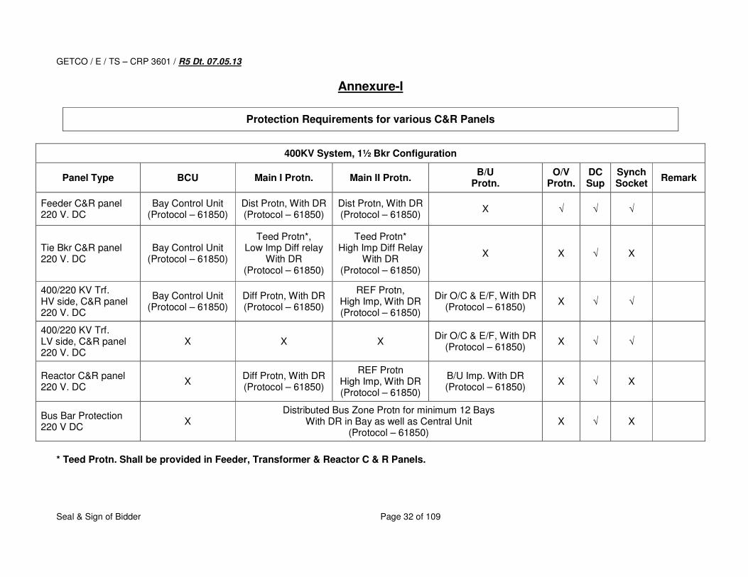
Annexure-I
Protection Requirements for various C&R Panels
400KV System, 1½ Bkr Configuration
Panel Type BCU Main I Protn. Main II Protn. B/U
Protn. O/V
Protn. DC Sup
Synch Socket
Remark
Feeder C&R panel 220 V. DC
Bay Control Unit (Protocol – 61850)
Dist Protn, With DR (Protocol – 61850)
Dist Protn, With DR (Protocol – 61850)
X √ √ √
Tie Bkr C&R panel 220 V. DC
Bay Control Unit (Protocol – 61850)
Teed Protn*, Low Imp Diff relay
With DR (Protocol – 61850)
Teed Protn* High Imp Diff Relay
With DR (Protocol – 61850)
X X √ X
400/220 KV Trf. HV side, C&R panel 220 V. DC
Bay Control Unit (Protocol – 61850)
Diff Protn, With DR (Protocol – 61850)
REF Protn, High Imp, With DR (Protocol – 61850)
Dir O/C & E/F, With DR (Protocol – 61850)
X √ √
400/220 KV Trf. LV side, C&R panel 220 V. DC
X X X Dir O/C & E/F, With DR
(Protocol – 61850) X √ √
Reactor C&R panel 220 V. DC
X Diff Protn, With DR (Protocol – 61850)
REF Protn High Imp, With DR (Protocol – 61850)
B/U Imp. With DR (Protocol – 61850)
X √ X
Bus Bar Protection 220 V DC
X Distributed Bus Zone Protn for minimum 12 Bays
With DR in Bay as well as Central Unit (Protocol – 61850)
X √ X
* Teed Protn. Shall be provided in Feeder, Transformer & Reactor C & R Panels.
GETCO / E / TS – CRP 3601 / R5 Dt. 07.05.13
Seal & Sign of Bidder Page 33 of 109
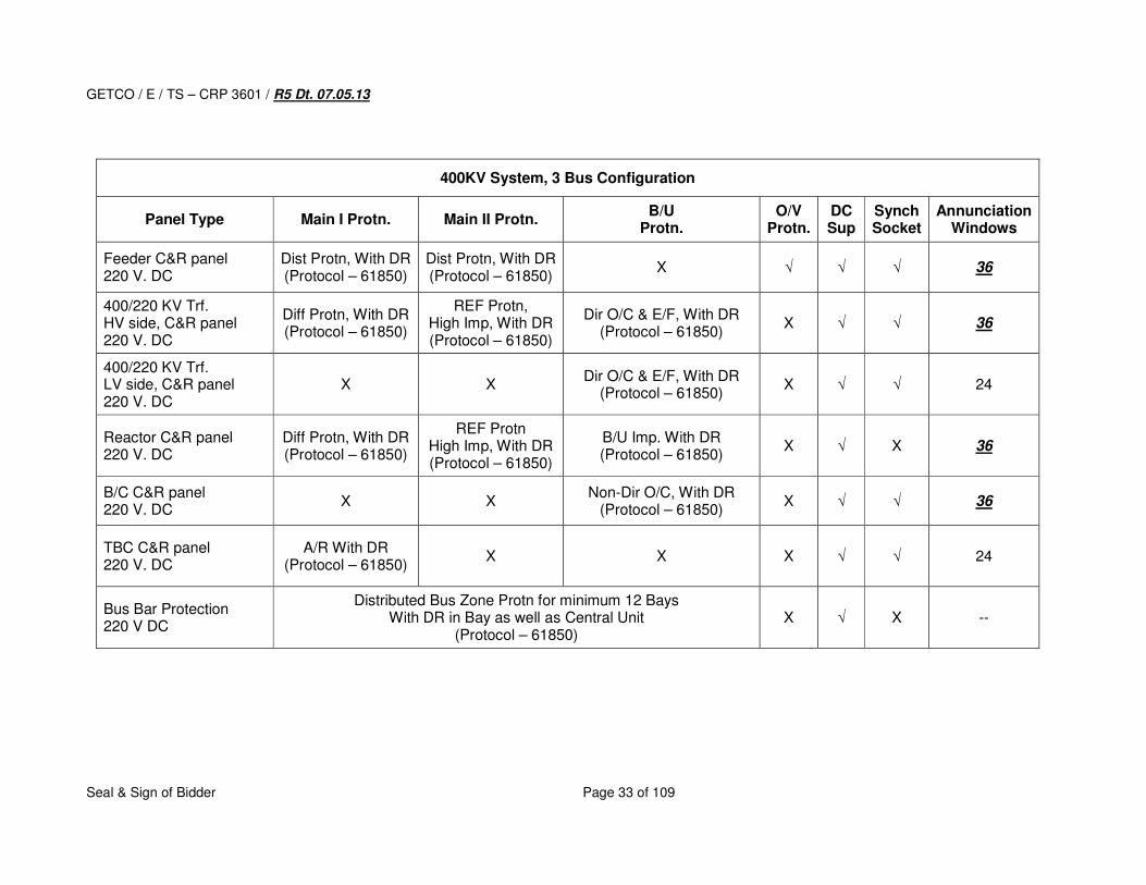
400KV System, 3 Bus Configuration
Panel Type Main I Protn. Main II Protn. B/U
Protn. O/V
Protn. DC Sup
Synch Socket
Annunciation Windows
Feeder C&R panel 220 V. DC
Dist Protn, With DR (Protocol – 61850)
Dist Protn, With DR (Protocol – 61850)
X √ √ √ 36
400/220 KV Trf. HV side, C&R panel 220 V. DC
Diff Protn, With DR (Protocol – 61850)
REF Protn, High Imp, With DR (Protocol – 61850)
Dir O/C & E/F, With DR (Protocol – 61850)
X √ √ 36
400/220 KV Trf. LV side, C&R panel 220 V. DC
X X Dir O/C & E/F, With DR
(Protocol – 61850) X √ √ 24
Reactor C&R panel 220 V. DC
Diff Protn, With DR (Protocol – 61850)
REF Protn High Imp, With DR (Protocol – 61850)
B/U Imp. With DR (Protocol – 61850)
X √ X 36
B/C C&R panel 220 V. DC
X X Non-Dir O/C, With DR
(Protocol – 61850) X √ √ 36
TBC C&R panel 220 V. DC
A/R With DR (Protocol – 61850)
X X X √ √ 24
Bus Bar Protection 220 V DC
Distributed Bus Zone Protn for minimum 12 Bays With DR in Bay as well as Central Unit
(Protocol – 61850) X √ X --
GETCO / E / TS – CRP 3601 / R5 Dt. 07.05.13
Seal & Sign of Bidder Page 34 of 109
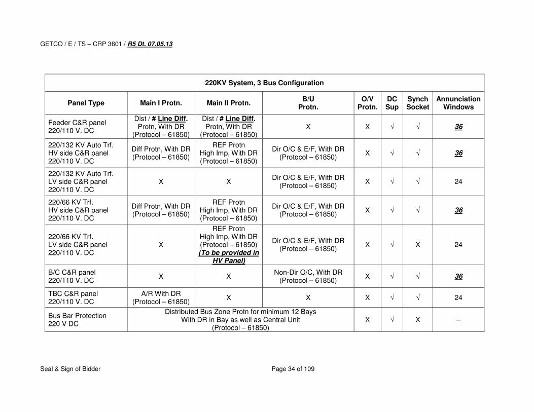
220KV System, 3 Bus Configuration
Panel Type Main I Protn. Main II Protn. B/U
Protn. O/V
Protn. DC Sup
Synch Socket
Annunciation Windows
Feeder C&R panel 220/110 V. DC
Dist / # Line Diff. Protn, With DR
(Protocol – 61850)
Dist / # Line Diff. Protn, With DR
(Protocol – 61850) X X √ √ 36
220/132 KV Auto Trf. HV side C&R panel 220/110 V. DC
Diff Protn, With DR (Protocol – 61850)
REF Protn High Imp, With DR (Protocol – 61850)
Dir O/C & E/F, With DR (Protocol – 61850)
X √ √ 36
220/132 KV Auto Trf. LV side C&R panel 220/110 V. DC
X X Dir O/C & E/F, With DR
(Protocol – 61850) X √ √ 24
220/66 KV Trf. HV side C&R panel 220/110 V. DC
Diff Protn, With DR (Protocol – 61850)
REF Protn High Imp, With DR (Protocol – 61850)
Dir O/C & E/F, With DR (Protocol – 61850)
X √ √ 36
220/66 KV Trf. LV side C&R panel 220/110 V. DC
X
REF Protn High Imp, With DR (Protocol – 61850) (To be provided in
HV Panel)
Dir O/C & E/F, With DR (Protocol – 61850)
X √ X 24
B/C C&R panel 220/110 V. DC
X X Non-Dir O/C, With DR
(Protocol – 61850) X √ √ 36
TBC C&R panel 220/110 V. DC
A/R With DR (Protocol – 61850)
X X X √ √ 24
Bus Bar Protection 220 V DC
Distributed Bus Zone Protn for minimum 12 Bays With DR in Bay as well as Central Unit
(Protocol – 61850) X √ X --
GETCO / E / TS – CRP 3601 / R5 Dt. 07.05.13
Seal & Sign of Bidder Page 35 of 109
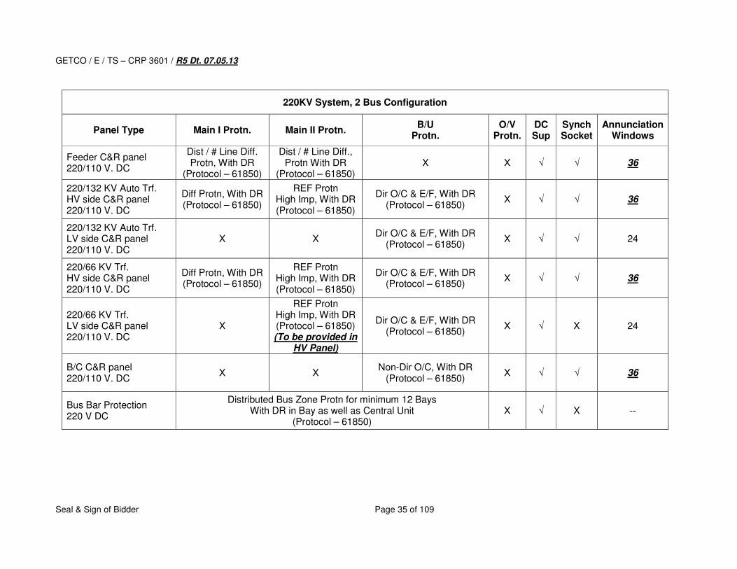
220KV System, 2 Bus Configuration
Panel Type Main I Protn. Main II Protn. B/U
Protn. O/V
Protn. DC Sup
Synch Socket
Annunciation Windows
Feeder C&R panel 220/110 V. DC
Dist / # Line Diff. Protn, With DR
(Protocol – 61850)
Dist / # Line Diff., Protn With DR
(Protocol – 61850) X X √ √ 36
220/132 KV Auto Trf. HV side C&R panel 220/110 V. DC
Diff Protn, With DR (Protocol – 61850)
REF Protn High Imp, With DR (Protocol – 61850)
Dir O/C & E/F, With DR (Protocol – 61850)
X √ √ 36
220/132 KV Auto Trf. LV side C&R panel 220/110 V. DC
X X Dir O/C & E/F, With DR
(Protocol – 61850) X √ √ 24
220/66 KV Trf. HV side C&R panel 220/110 V. DC
Diff Protn, With DR (Protocol – 61850)
REF Protn High Imp, With DR (Protocol – 61850)
Dir O/C & E/F, With DR (Protocol – 61850)
X √ √ 36
220/66 KV Trf. LV side C&R panel 220/110 V. DC
X
REF Protn High Imp, With DR (Protocol – 61850) (To be provided in
HV Panel)
Dir O/C & E/F, With DR (Protocol – 61850)
X √ X 24
B/C C&R panel 220/110 V. DC
X X Non-Dir O/C, With DR
(Protocol – 61850) X √ √ 36
Bus Bar Protection 220 V DC
Distributed Bus Zone Protn for minimum 12 Bays With DR in Bay as well as Central Unit
(Protocol – 61850) X √ X --
GETCO / E / TS – CRP 3601 / R5 Dt. 07.05.13
Seal & Sign of Bidder Page 36 of 109
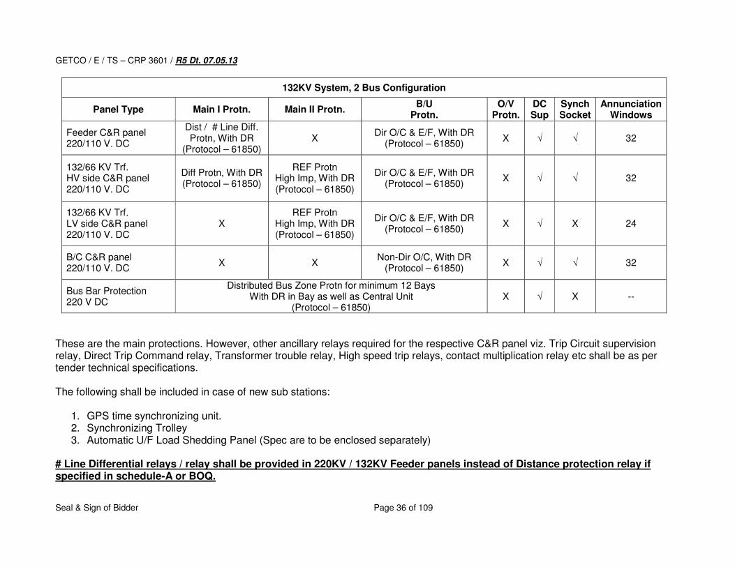
132KV System, 2 Bus Configuration
Panel Type Main I Protn. Main II Protn. B/U
Protn. O/V
Protn. DC Sup
Synch Socket
Annunciation Windows
Feeder C&R panel 220/110 V. DC
Dist / # Line Diff. Protn, With DR
(Protocol – 61850) X
Dir O/C & E/F, With DR (Protocol – 61850)
X √ √ 32
132/66 KV Trf. HV side C&R panel 220/110 V. DC
Diff Protn, With DR (Protocol – 61850)
REF Protn High Imp, With DR (Protocol – 61850)
Dir O/C & E/F, With DR (Protocol – 61850)
X √ √ 32
132/66 KV Trf. LV side C&R panel 220/110 V. DC
X REF Protn
High Imp, With DR (Protocol – 61850)
Dir O/C & E/F, With DR (Protocol – 61850)
X √ X 24
B/C C&R panel 220/110 V. DC
X X Non-Dir O/C, With DR
(Protocol – 61850) X √ √ 32
Bus Bar Protection 220 V DC
Distributed Bus Zone Protn for minimum 12 Bays With DR in Bay as well as Central Unit
(Protocol – 61850) X √ X --
These are the main protections. However, other ancillary relays required for the respective C&R panel viz. Trip Circuit supervision relay, Direct Trip Command relay, Transformer trouble relay, High speed trip relays, contact multiplication relay etc shall be as per tender technical specifications. The following shall be included in case of new sub stations:
1. GPS time synchronizing unit. 2. Synchronizing Trolley 3. Automatic U/F Load Shedding Panel (Spec are to be enclosed separately)
# Line Differential relays / relay shall be provided in 220KV / 132KV Feeder panels instead of Distance protection relay if specified in schedule-A or BOQ.
GETCO / E / TS – CRP 3601 / R5 Dt. 07.05.13
Seal & Sign of Bidder Page 37 of 109
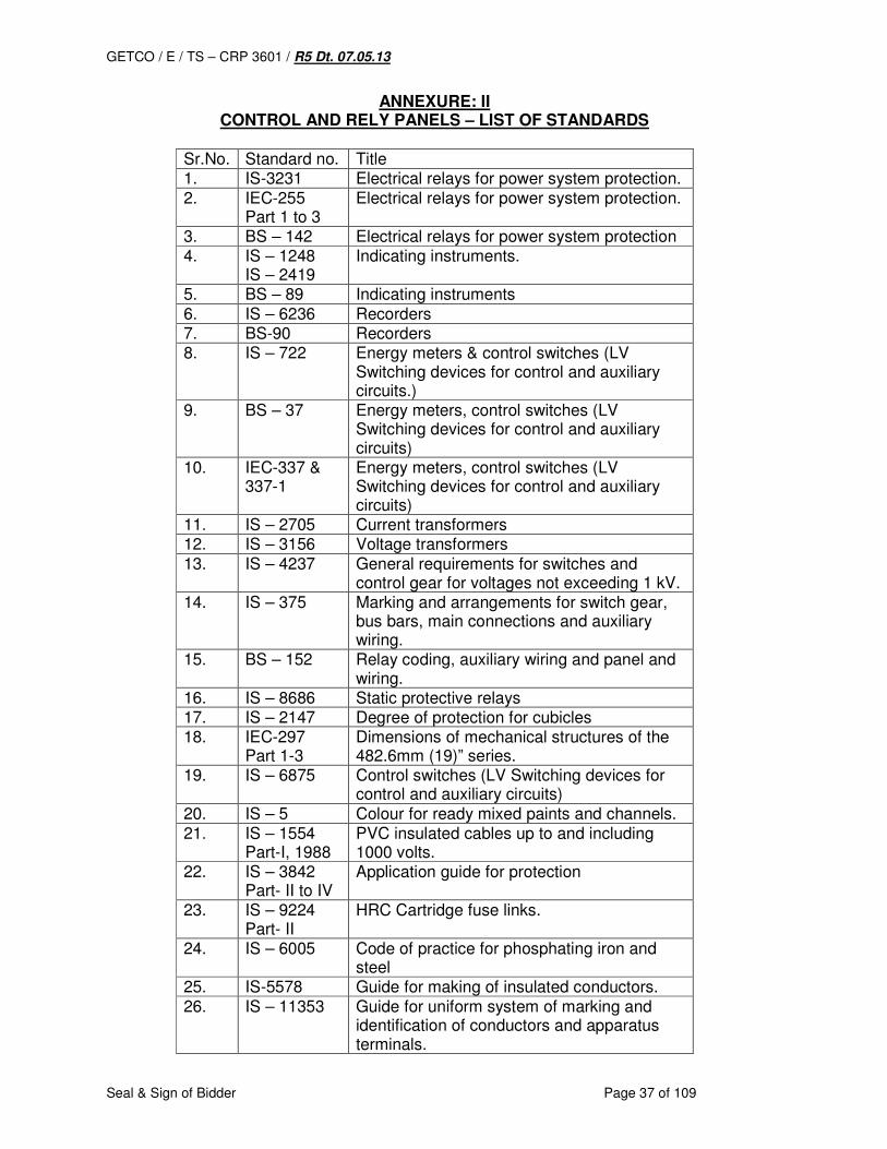
ANNEXURE: II CONTROL AND RELY PANELS – LIST OF STANDARDS
Sr.No. Standard no. Title 1. IS-3231 Electrical relays for power system protection. 2. IEC-255
Part 1 to 3 Electrical relays for power system protection.
3. BS – 142 Electrical relays for power system protection 4. IS – 1248
IS – 2419 Indicating instruments.
5. BS – 89 Indicating instruments 6. IS – 6236 Recorders 7. BS-90 Recorders 8. IS – 722 Energy meters & control switches (LV
Switching devices for control and auxiliary circuits.)
9. BS – 37 Energy meters, control switches (LV Switching devices for control and auxiliary circuits)
10. IEC-337 & 337-1
Energy meters, control switches (LV Switching devices for control and auxiliary circuits)
11. IS – 2705 Current transformers 12. IS – 3156 Voltage transformers 13. IS – 4237 General requirements for switches and
control gear for voltages not exceeding 1 kV. 14. IS – 375 Marking and arrangements for switch gear,
bus bars, main connections and auxiliary wiring.
15. BS – 152 Relay coding, auxiliary wiring and panel and wiring.
16. IS – 8686 Static protective relays 17. IS – 2147 Degree of protection for cubicles 18. IEC-297
Part 1-3 Dimensions of mechanical structures of the 482.6mm (19)” series.
19. IS – 6875 Control switches (LV Switching devices for control and auxiliary circuits)
20. IS – 5 Colour for ready mixed paints and channels. 21. IS – 1554
Part-I, 1988 PVC insulated cables up to and including 1000 volts.
22. IS – 3842 Part- II to IV
Application guide for protection
23. IS – 9224 Part- II
HRC Cartridge fuse links.
24. IS – 6005 Code of practice for phosphating iron and steel
25. IS-5578 Guide for making of insulated conductors. 26. IS – 11353 Guide for uniform system of marking and
identification of conductors and apparatus terminals.
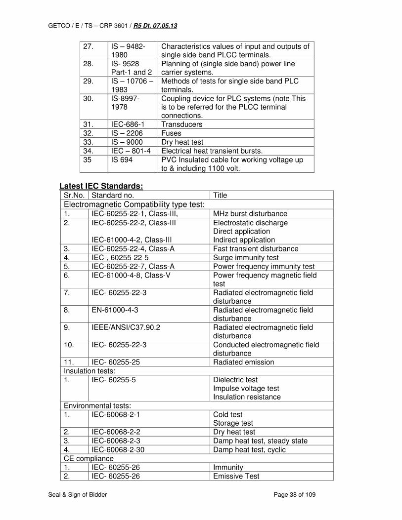
GETCO / E / TS – CRP 3601 / R5 Dt. 07.05.13
Seal & Sign of Bidder Page 38 of 109
27. IS – 9482-1980
Characteristics values of input and outputs of single side band PLCC terminals.
28. IS- 9528 Part-1 and 2
Planning of (single side band) power line carrier systems.
29. IS – 10706 – 1983
Methods of tests for single side band PLC terminals.
30. IS-8997-1978
Coupling device for PLC systems (note This is to be referred for the PLCC terminal connections.
31. IEC-686-1 Transducers 32. IS – 2206 Fuses 33. IS – 9000 Dry heat test 34. IEC – 801-4 Electrical heat transient bursts. 35 IS 694 PVC Insulated cable for working voltage up
to & including 1100 volt.
Latest IEC Standards: Sr.No. Standard no. Title
Electromagnetic Compatibility type test: 1. IEC-60255-22-1, Class-III, MHz burst disturbance
2. IEC-60255-22-2, Class-III IEC-61000-4-2, Class-III
Electrostatic discharge Direct application Indirect application
3. IEC-60255-22-4, Class-A Fast transient disturbance 4. IEC-, 60255-22-5 Surge immunity test 5. IEC-60255-22-7, Class-A Power frequency immunity test 6. IEC-61000-4-8, Class-V Power frequency magnetic field
test 7. IEC- 60255-22-3 Radiated electromagnetic field
disturbance 8. EN-61000-4-3 Radiated electromagnetic field
disturbance 9. IEEE/ANSI/C37.90.2 Radiated electromagnetic field
disturbance 10. IEC- 60255-22-3 Conducted electromagnetic field
disturbance 11. IEC- 60255-25 Radiated emission Insulation tests: 1. IEC- 60255-5 Dielectric test
Impulse voltage test Insulation resistance
Environmental tests: 1. IEC-60068-2-1 Cold test
Storage test 2. IEC-60068-2-2 Dry heat test 3. IEC-60068-2-3 Damp heat test, steady state 4. IEC-60068-2-30 Damp heat test, cyclic CE compliance 1. IEC- 60255-26 Immunity 2. IEC- 60255-26 Emissive Test

GETCO / E / TS – CRP 3601 / R5 Dt. 07.05.13
Seal & Sign of Bidder Page 39 of 109
3. EN-50178 Low voltage directive Mechanical tests 1. IEC- 60255-21-1 Vibration 2. IEC- 60255-21-2 Shock and bump 3. IEC- 60255-21-3 Seismic
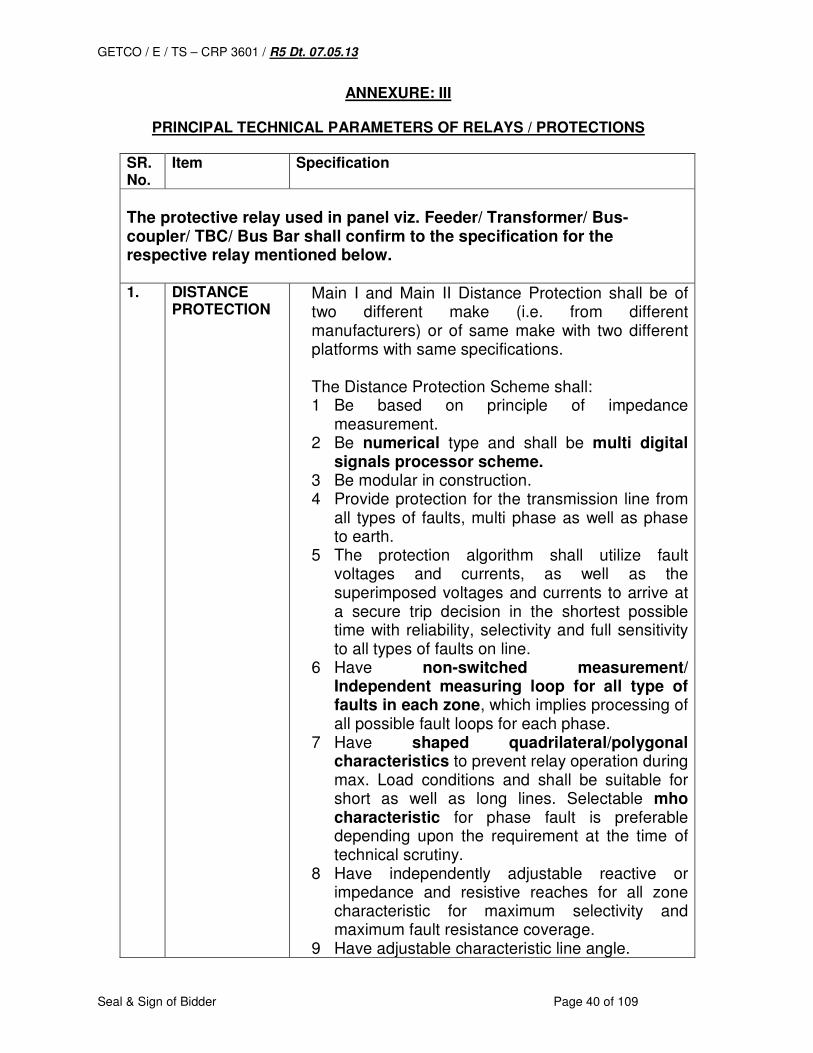
GETCO / E / TS – CRP 3601 / R5 Dt. 07.05.13
Seal & Sign of Bidder Page 40 of 109
ANNEXURE: III
PRINCIPAL TECHNICAL PARAMETERS OF RELAYS / PROTECTIONS
SR. No.
Item Specification
The protective relay used in panel viz. Feeder/ Transformer/ Bus-coupler/ TBC/ Bus Bar shall confirm to the specification for the respective relay mentioned below. 1. DISTANCE
PROTECTION
Main I and Main II Distance Protection shall be of two different make (i.e. from different manufacturers) or of same make with two different platforms with same specifications. The Distance Protection Scheme shall: 1 Be based on principle of impedance
measurement. 2 Be numerical type and shall be multi digital
signals processor scheme. 3 Be modular in construction. 4 Provide protection for the transmission line from
all types of faults, multi phase as well as phase to earth.
5 The protection algorithm shall utilize fault voltages and currents, as well as the superimposed voltages and currents to arrive at a secure trip decision in the shortest possible time with reliability, selectivity and full sensitivity to all types of faults on line.
6 Have non-switched measurement/ Independent measuring loop for all type of faults in each zone, which implies processing of all possible fault loops for each phase.
7 Have shaped quadrilateral/polygonal characteristics to prevent relay operation during max. Load conditions and shall be suitable for short as well as long lines. Selectable mho characteristic for phase fault is preferable depending upon the requirement at the time of technical scrutiny.
8 Have independently adjustable reactive or impedance and resistive reaches for all zone characteristic for maximum selectivity and maximum fault resistance coverage.
9 Have adjustable characteristic line angle.
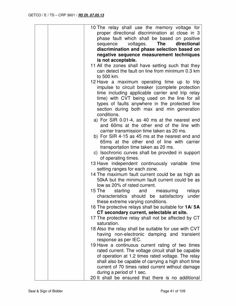
GETCO / E / TS – CRP 3601 / R5 Dt. 07.05.13
Seal & Sign of Bidder Page 41 of 109
10 The relay shall use the memory voltage for proper directional discrimination at close in 3 phase fault which shall be based on positive sequence voltages. The directional discrimination and phase selection based on negative sequence measurement techniques is not acceptable.
11 All the zones shall have setting such that they can detect the fault on line from minimum 0.3 km to 500 km.
12 Have a maximum operating time up to trip impulse to circuit breaker (complete protection time including applicable carrier and trip relay time) with CVT being used on the line for all types of faults anywhere in the protected line section during both max and min generation conditions.
a) For SIR 0.01-4, as 40 ms at the nearest end and 60ms at the other end of the line with carrier transmission time taken as 20 ms.
b) For SIR 4-15 as 45 ms at the nearest end and 65ms at the other end of line with carrier transportation time taken as 20 ms.
c) Isochronic curves shall be provided in support of operating times.
13 Have independent continuously variable time setting ranges for each zone.
14 The maximum fault current could be as high as 50kA but the minimum fault current could be as low as 20% of rated current.
15 The starting and measuring relays characteristics should be satisfactory under these extreme varying conditions.
16 The protective relays shall be suitable for 1A/ 5A CT secondary current, selectable at site.
17 The protective relay shall not be affected by CT saturation.
18 Also the relay shall be suitable for use with CVT having non-electronic damping and transient response as per IEC.
19 Have a continuous current rating of two times rated current. The voltage circuit shall be capable of operation at 1.2 times rated voltage. The relay shall also be capable of carrying a high short time current of 70 times rated current without damage during a period of 1 sec.
20 It shall be ensured that there is no additional

GETCO / E / TS – CRP 3601 / R5 Dt. 07.05.13
Seal & Sign of Bidder Page 42 of 109
delay in relay operating time created intentionally to have stable operation.
21 Numerical full scheme distance protection terminal shall be suitable for use with any communication scheme (permissive under reach, over reach, blocking) and have facility for connection to sub – station control system.
22 The scheme shall have input transformation modules, analogue and digital filters, processing units, A/D and D/A converters, DC supply modules etc.
23 The sampling rate of analogue inputs, the processing speed and processing cycle of digital values shall be selected so as to achieve the operating time specified.
24 Be capable of performing basic instrumentation functions and display on demand of various measured parameters like voltage, current, active power, reactive power, etc. in primary values. Additionally all sequence current and voltage values, direction of power flow, alarms and clock, relay identification, settings etc. during normal as well as fault conditions on individual phase basis shall be displayed on line. Pre fault and fault values of current and voltage must be available for fault analysis purpose.
25 Have a MMI (Man Machine Interface) in the front of relay comprising of a 2-3 line alphanumeric LCD display.
26 Facilities shall be available through a soft touch keypad on the MMI for setting alteration, display of all settings, scheme logics and any other requirements as per the software and hardware configuration of the system other than the menu driven alarms.
27 Have a front/rear RS 232 – Communication part for use with a PC locating for local access to settings, events and records.
28 Have one rear communication port on fiber optic medium or remote communication based on RS 485 connectivity to support (1) all the facilities available via the integral user interface and (2) facilities supported under IEC-61850-8-1 interface.
29 Shall be provided with standard protocols and changing of protocols must be possible at a
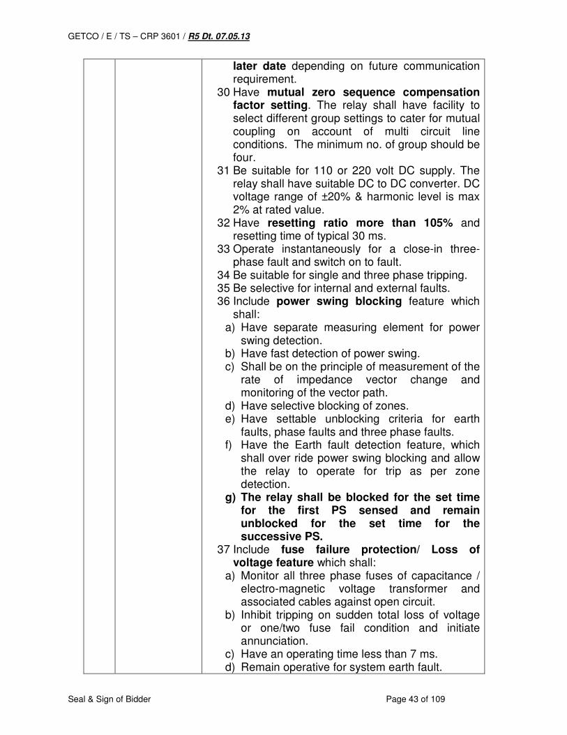
GETCO / E / TS – CRP 3601 / R5 Dt. 07.05.13
Seal & Sign of Bidder Page 43 of 109
later date depending on future communication requirement.
30 Have mutual zero sequence compensation factor setting. The relay shall have facility to select different group settings to cater for mutual coupling on account of multi circuit line conditions. The minimum no. of group should be four.
31 Be suitable for 110 or 220 volt DC supply. The relay shall have suitable DC to DC converter. DC voltage range of ±20% & harmonic level is max 2% at rated value.
32 Have resetting ratio more than 105% and resetting time of typical 30 ms.
33 Operate instantaneously for a close-in three-phase fault and switch on to fault.
34 Be suitable for single and three phase tripping. 35 Be selective for internal and external faults. 36 Include power swing blocking feature which
shall: a) Have separate measuring element for power
swing detection. b) Have fast detection of power swing. c) Shall be on the principle of measurement of the
rate of impedance vector change and monitoring of the vector path.
d) Have selective blocking of zones. e) Have settable unblocking criteria for earth
faults, phase faults and three phase faults. f) Have the Earth fault detection feature, which
shall over ride power swing blocking and allow the relay to operate for trip as per zone detection.
g) The relay shall be blocked for the set time for the first PS sensed and remain unblocked for the set time for the successive PS.
37 Include fuse failure protection/ Loss of voltage feature which shall:
a) Monitor all three phase fuses of capacitance / electro-magnetic voltage transformer and associated cables against open circuit.
b) Inhibit tripping on sudden total loss of voltage or one/two fuse fail condition and initiate annunciation.
c) Have an operating time less than 7 ms. d) Remain operative for system earth fault.
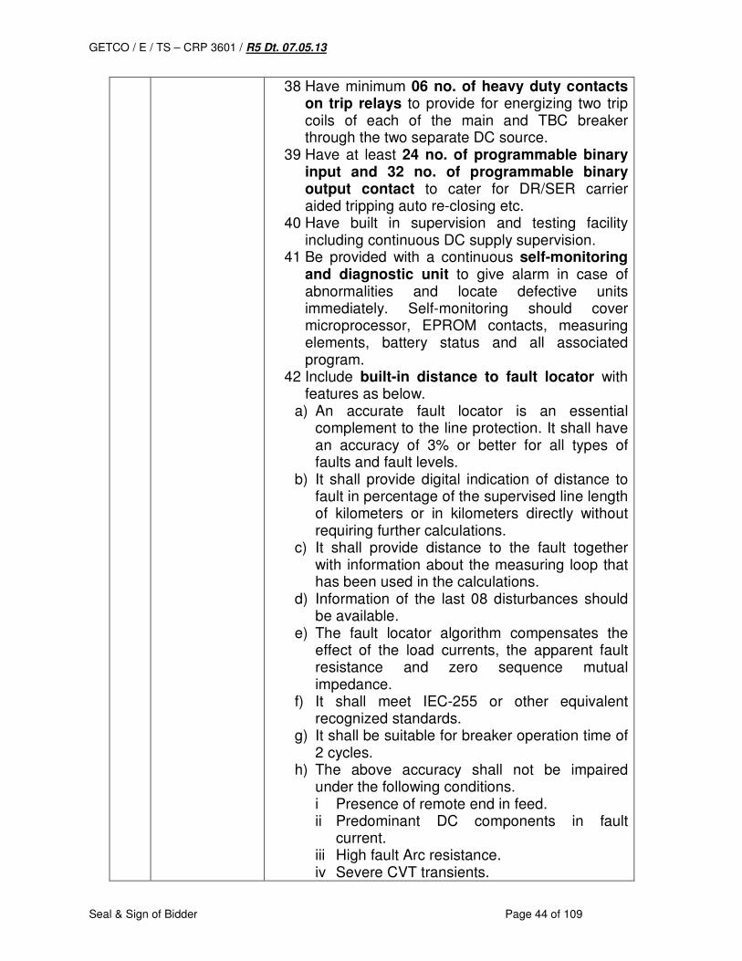
GETCO / E / TS – CRP 3601 / R5 Dt. 07.05.13
Seal & Sign of Bidder Page 44 of 109
38 Have minimum 06 no. of heavy duty contacts on trip relays to provide for energizing two trip coils of each of the main and TBC breaker through the two separate DC source.
39 Have at least 24 no. of programmable binary input and 32 no. of programmable binary output contact to cater for DR/SER carrier aided tripping auto re-closing etc.
40 Have built in supervision and testing facility including continuous DC supply supervision.
41 Be provided with a continuous self-monitoring and diagnostic unit to give alarm in case of abnormalities and locate defective units immediately. Self-monitoring should cover microprocessor, EPROM contacts, measuring elements, battery status and all associated program.
42 Include built-in distance to fault locator with features as below.
a) An accurate fault locator is an essential complement to the line protection. It shall have an accuracy of 3% or better for all types of faults and fault levels.
b) It shall provide digital indication of distance to fault in percentage of the supervised line length of kilometers or in kilometers directly without requiring further calculations.
c) It shall provide distance to the fault together with information about the measuring loop that has been used in the calculations.
d) Information of the last 08 disturbances should be available.
e) The fault locator algorithm compensates the effect of the load currents, the apparent fault resistance and zero sequence mutual impedance.
f) It shall meet IEC-255 or other equivalent recognized standards.
g) It shall be suitable for breaker operation time of 2 cycles.
h) The above accuracy shall not be impaired under the following conditions. i Presence of remote end in feed. ii Predominant DC components in fault
current. iii High fault Arc resistance. iv Severe CVT transients.
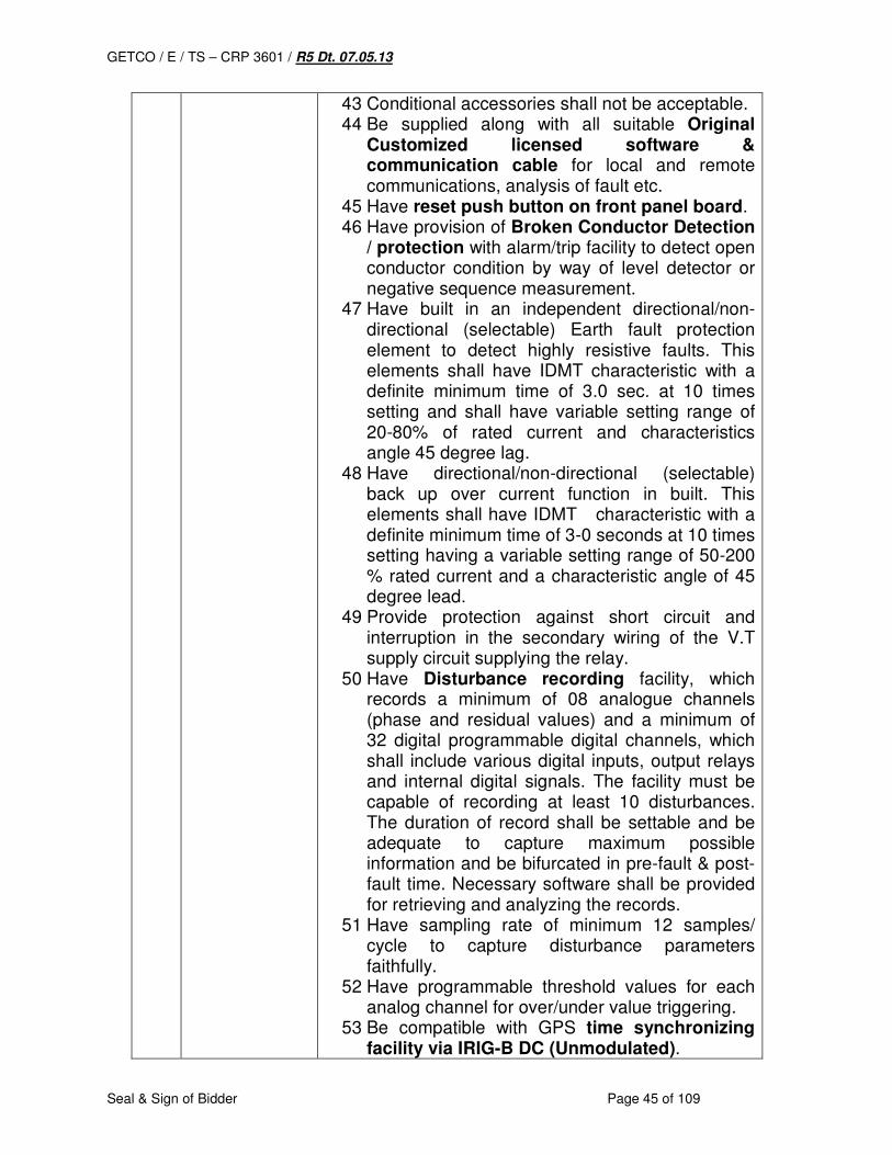
GETCO / E / TS – CRP 3601 / R5 Dt. 07.05.13
Seal & Sign of Bidder Page 45 of 109
43 Conditional accessories shall not be acceptable. 44 Be supplied along with all suitable Original
Customized licensed software & communication cable for local and remote communications, analysis of fault etc.
45 Have reset push button on front panel board. 46 Have provision of Broken Conductor Detection
/ protection with alarm/trip facility to detect open conductor condition by way of level detector or negative sequence measurement.
47 Have built in an independent directional/non-directional (selectable) Earth fault protection element to detect highly resistive faults. This elements shall have IDMT characteristic with a definite minimum time of 3.0 sec. at 10 times setting and shall have variable setting range of 20-80% of rated current and characteristics angle 45 degree lag.
48 Have directional/non-directional (selectable) back up over current function in built. This elements shall have IDMT characteristic with a definite minimum time of 3-0 seconds at 10 times setting having a variable setting range of 50-200 % rated current and a characteristic angle of 45 degree lead.
49 Provide protection against short circuit and interruption in the secondary wiring of the V.T supply circuit supplying the relay.
50 Have Disturbance recording facility, which records a minimum of 08 analogue channels (phase and residual values) and a minimum of 32 digital programmable digital channels, which shall include various digital inputs, output relays and internal digital signals. The facility must be capable of recording at least 10 disturbances. The duration of record shall be settable and be adequate to capture maximum possible information and be bifurcated in pre-fault & post-fault time. Necessary software shall be provided for retrieving and analyzing the records.
51 Have sampling rate of minimum 12 samples/ cycle to capture disturbance parameters faithfully.
52 Have programmable threshold values for each analog channel for over/under value triggering.
53 Be compatible with GPS time synchronizing facility via IRIG-B DC (Unmodulated).

GETCO / E / TS – CRP 3601 / R5 Dt. 07.05.13
Seal & Sign of Bidder Page 46 of 109
54 Have additional protection functionality over and above mentioned earlier such as:
a) Current reversal and weak end infeed protection logic.
b) SOTF feature. c) Over / under voltage protection. d) Breaker failure protection. e) Dead line Detection. f) Auto re-closure with synchro-check facility.
55 Have non volatile storage of DR & SER and also have real time clock buffered by Battery or any other
suitable means. In case of Battery; it shall be reliable and long lasting. There shall be an alarm and indication for declining battery status.
56 Auto re-closing feature shall be included in the Numerical Distance Protection Scheme as a built-in feature. It shall
a) Have single phase and three phase re-closing facilities
b) Have a continuously variable single phase dead time of 0.5 to 5 seconds
c) Have continuously variable three phase dead time range of 0.5 to 5 seconds.
d) Have a continuously variable reclaim time range of 5-25 seconds
e) Incorporate a four-position selector switch from which single phase/three phase/single and three phase/auto re-closure and non-auto re-closure mode can be selected
f) Have facilities for selecting check synchronizing or dead line charging features. It shall be possible at any time to change the required feature by reconnection of links.
g) Be of multishot type h) Include check synchronizing relay which shall
i Have a time setting variable between 0.5 to 5 seconds.
ii Have a response time within 200 ms with the timer disconnected.
i) Include dead line charging relay. j) Incorporate necessary auxiliary relays and
timers to give comprehensive scheme. k) Incorporate a separate pole discrepancy relay
with timing range of 0.1 to 1 sec l) Auto re-closure of the line shall take place only
when fault is cleared in first zone by the main protection.
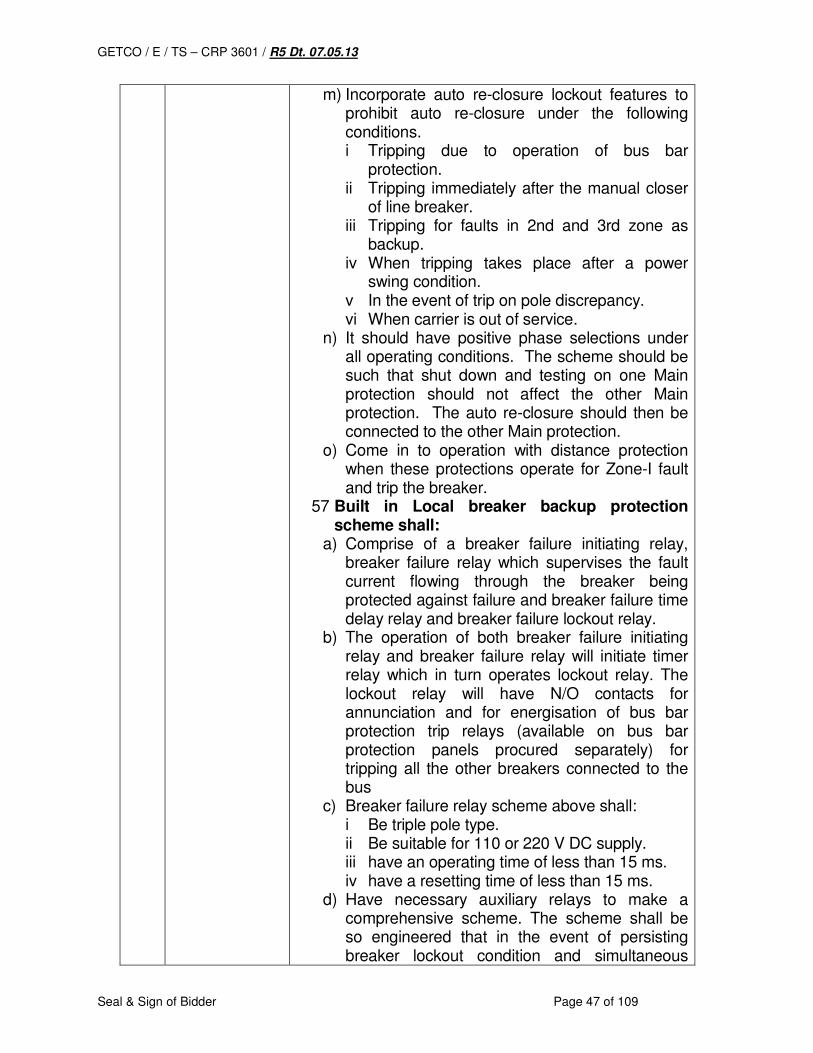
GETCO / E / TS – CRP 3601 / R5 Dt. 07.05.13
Seal & Sign of Bidder Page 47 of 109
m) Incorporate auto re-closure lockout features to prohibit auto re-closure under the following conditions. i Tripping due to operation of bus bar
protection. ii Tripping immediately after the manual closer
of line breaker. iii Tripping for faults in 2nd and 3rd zone as
backup. iv When tripping takes place after a power
swing condition. v In the event of trip on pole discrepancy. vi When carrier is out of service.
n) It should have positive phase selections under all operating conditions. The scheme should be such that shut down and testing on one Main protection should not affect the other Main protection. The auto re-closure should then be connected to the other Main protection.
o) Come in to operation with distance protection when these protections operate for Zone-I fault and trip the breaker.
57 Built in Local breaker backup protection scheme shall:
a) Comprise of a breaker failure initiating relay, breaker failure relay which supervises the fault current flowing through the breaker being protected against failure and breaker failure time delay relay and breaker failure lockout relay.
b) The operation of both breaker failure initiating relay and breaker failure relay will initiate timer relay which in turn operates lockout relay. The lockout relay will have N/O contacts for annunciation and for energisation of bus bar protection trip relays (available on bus bar protection panels procured separately) for tripping all the other breakers connected to the bus
c) Breaker failure relay scheme above shall: i Be triple pole type. ii Be suitable for 110 or 220 V DC supply. iii have an operating time of less than 15 ms. iv have a resetting time of less than 15 ms.
d) Have necessary auxiliary relays to make a comprehensive scheme. The scheme shall be so engineered that in the event of persisting breaker lockout condition and simultaneous
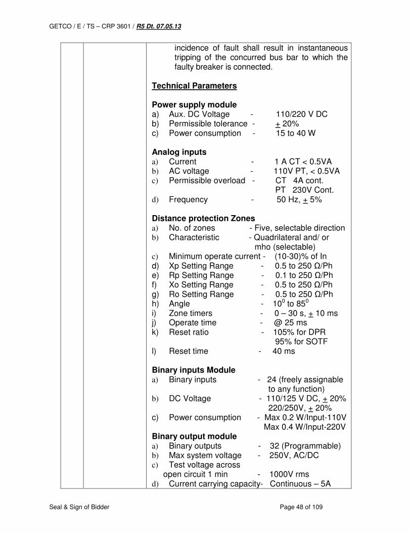
GETCO / E / TS – CRP 3601 / R5 Dt. 07.05.13
Seal & Sign of Bidder Page 48 of 109
incidence of fault shall result in instantaneous tripping of the concurred bus bar to which the faulty breaker is connected.
Technical Parameters Power supply module a) Aux. DC Voltage - 110/220 V DC b) Permissible tolerance - + 20% c) Power consumption - 15 to 40 W Analog inputs a) Current - 1 A CT < 0.5VA
b) AC voltage - 110V PT, < 0.5VA
c) Permissible overload - CT 4A cont. PT 230V Cont. d) Frequency - 50 Hz, + 5%
Distance protection Zones a) No. of zones - Five, selectable direction
b) Characteristic - Quadrilateral and/ or mho (selectable) c) Minimum operate current - (10-30)% of In
d) Xp Setting Range - 0.5 to 250 Ω/Ph e) Rp Setting Range - 0.1 to 250 Ω/Ph f) Xo Setting Range - 0.5 to 250 Ω/Ph g) Ro Setting Range - 0.5 to 250 Ω/Ph h) Angle - 100 to 850 i) Zone timers - 0 – 30 s, + 10 ms j) Operate time - @ 25 ms k) Reset ratio - 105% for DPR 95% for SOTF l) Reset time - 40 ms Binary inputs Module a) Binary inputs - 24 (freely assignable
to any function) b) DC Voltage - 110/125 V DC, + 20%
220/250V, + 20% c) Power consumption - Max 0.2 W/Input-110V Max 0.4 W/Input-220V Binary output module a) Binary outputs - 32 (Programmable) b) Max system voltage - 250V, AC/DC
c) Test voltage across
open circuit 1 min - 1000V rms d) Current carrying capacity- Continuous – 5A
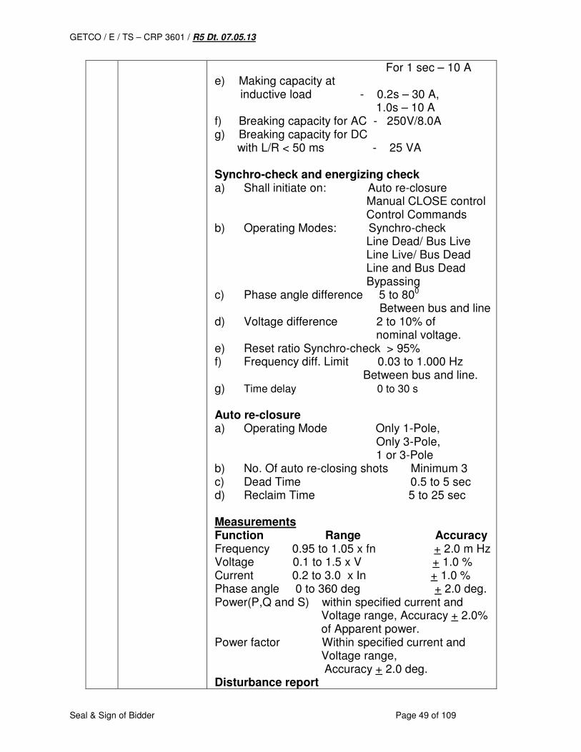
GETCO / E / TS – CRP 3601 / R5 Dt. 07.05.13
Seal & Sign of Bidder Page 49 of 109
For 1 sec – 10 A e) Making capacity at inductive load - 0.2s – 30 A, 1.0s – 10 A f) Breaking capacity for AC - 250V/8.0A g) Breaking capacity for DC with L/R < 50 ms - 25 VA Synchro-check and energizing check a) Shall initiate on: Auto re-closure Manual CLOSE control Control Commands b) Operating Modes: Synchro-check Line Dead/ Bus Live Line Live/ Bus Dead Line and Bus Dead Bypassing c) Phase angle difference 5 to 800 Between bus and line d) Voltage difference 2 to 10% of nominal voltage. e) Reset ratio Synchro-check > 95% f) Frequency diff. Limit 0.03 to 1.000 Hz Between bus and line. g) Time delay 0 to 30 s Auto re-closure a) Operating Mode Only 1-Pole, Only 3-Pole, 1 or 3-Pole b) No. Of auto re-closing shots Minimum 3 c) Dead Time 0.5 to 5 sec d) Reclaim Time 5 to 25 sec Measurements Function Range Accuracy Frequency 0.95 to 1.05 x fn + 2.0 m Hz Voltage 0.1 to 1.5 x V + 1.0 % Current 0.2 to 3.0 x In + 1.0 % Phase angle 0 to 360 deg + 2.0 deg. Power(P,Q and S) within specified current and Voltage range, Accuracy + 2.0% of Apparent power. Power factor Within specified current and Voltage range, Accuracy + 2.0 deg. Disturbance report
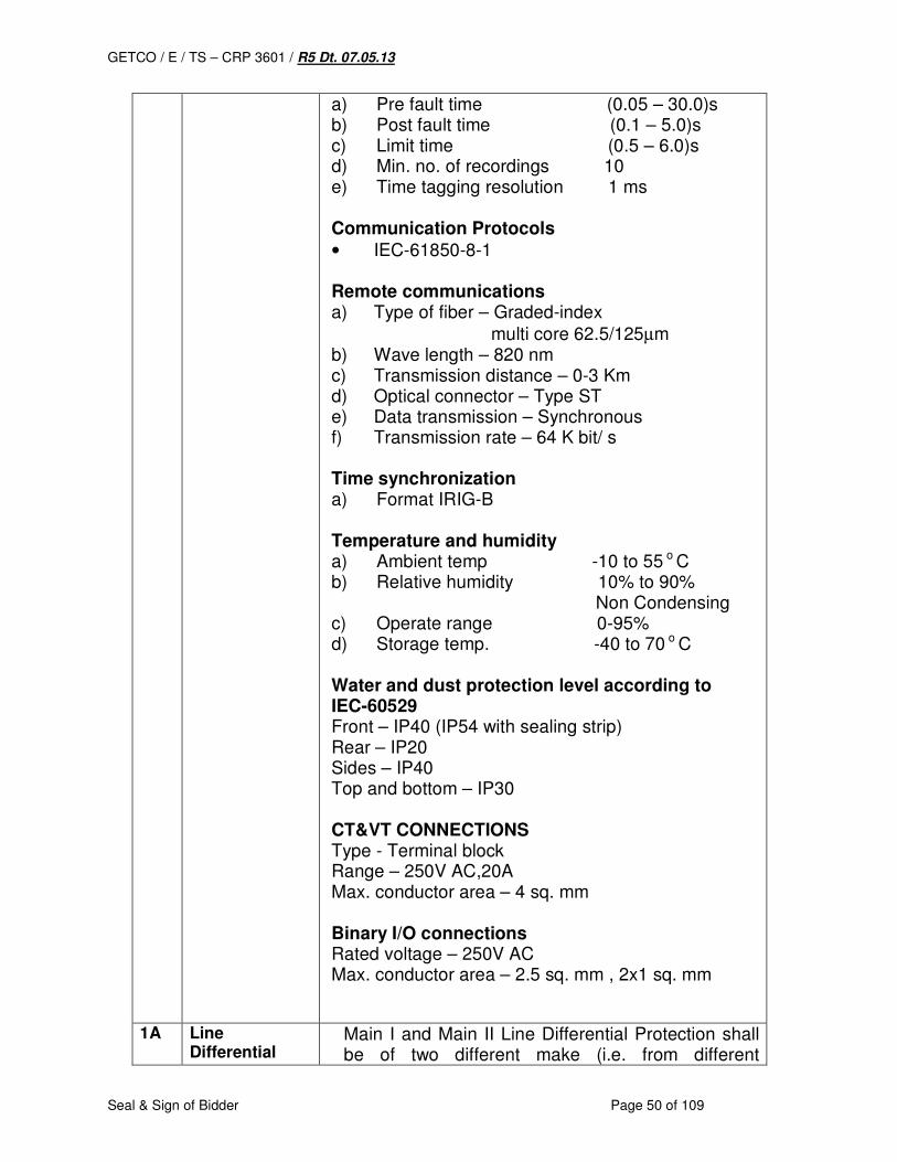
GETCO / E / TS – CRP 3601 / R5 Dt. 07.05.13
Seal & Sign of Bidder Page 50 of 109
a) Pre fault time (0.05 – 30.0)s b) Post fault time (0.1 – 5.0)s c) Limit time (0.5 – 6.0)s d) Min. no. of recordings 10 e) Time tagging resolution 1 ms Communication Protocols • IEC-61850-8-1 Remote communications a) Type of fiber – Graded-index
multi core 62.5/125µm b) Wave length – 820 nm c) Transmission distance – 0-3 Km d) Optical connector – Type ST e) Data transmission – Synchronous f) Transmission rate – 64 K bit/ s Time synchronization a) Format IRIG-B Temperature and humidity a) Ambient temp -10 to 55 o C b) Relative humidity 10% to 90% Non Condensing c) Operate range 0-95% d) Storage temp. -40 to 70 o C Water and dust protection level according to IEC-60529 Front – IP40 (IP54 with sealing strip) Rear – IP20 Sides – IP40 Top and bottom – IP30 CT&VT CONNECTIONS Type - Terminal block Range – 250V AC,20A Max. conductor area – 4 sq. mm Binary I/O connections Rated voltage – 250V AC Max. conductor area – 2.5 sq. mm , 2x1 sq. mm
1A Line Differential
Main I and Main II Line Differential Protection shall be of two different make (i.e. from different
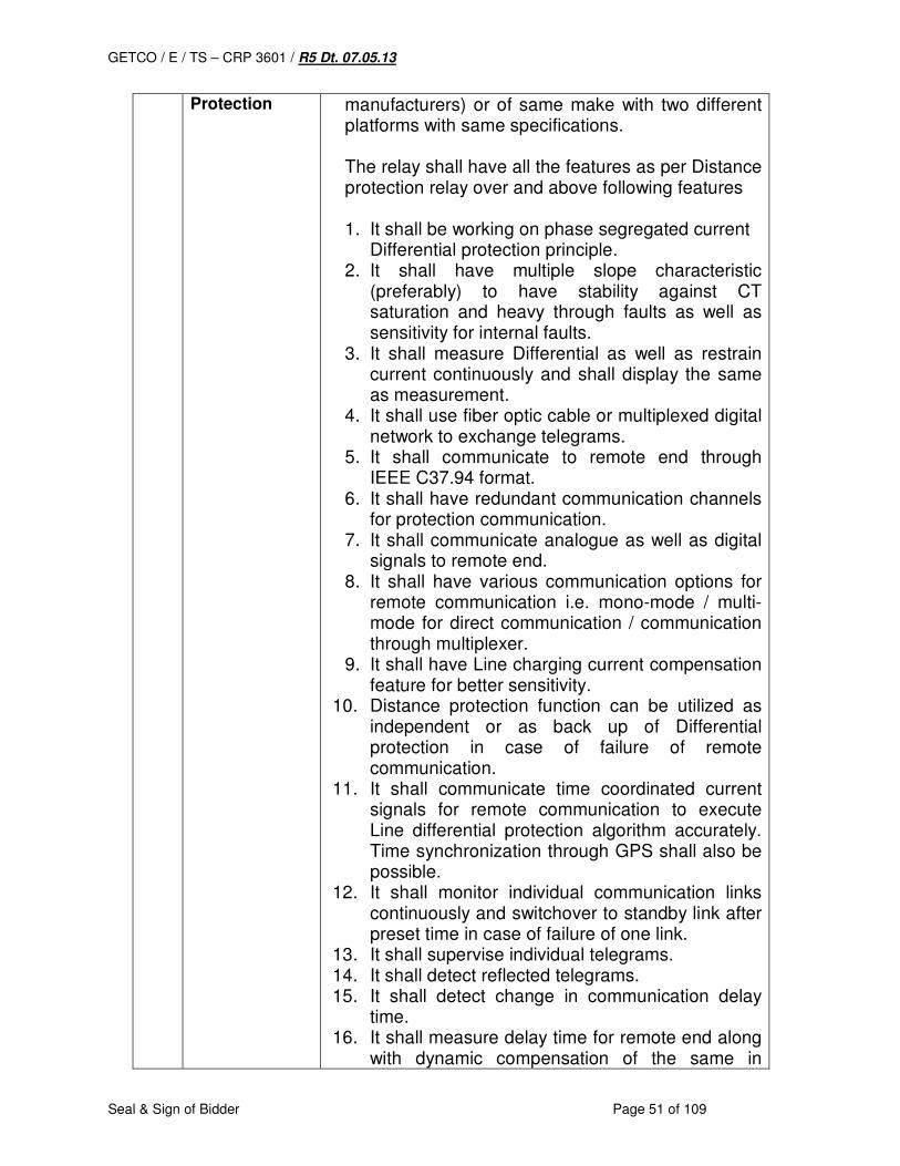
GETCO / E / TS – CRP 3601 / R5 Dt. 07.05.13
Seal & Sign of Bidder Page 51 of 109
Protection manufacturers) or of same make with two different platforms with same specifications. The relay shall have all the features as per Distance protection relay over and above following features 1. It shall be working on phase segregated current Differential protection principle. 2. It shall have multiple slope characteristic
(preferably) to have stability against CT saturation and heavy through faults as well as sensitivity for internal faults.
3. It shall measure Differential as well as restrain current continuously and shall display the same as measurement.
4. It shall use fiber optic cable or multiplexed digital network to exchange telegrams.
5. It shall communicate to remote end through IEEE C37.94 format.
6. It shall have redundant communication channels for protection communication.
7. It shall communicate analogue as well as digital signals to remote end.
8. It shall have various communication options for remote communication i.e. mono-mode / multi-mode for direct communication / communication through multiplexer.
9. It shall have Line charging current compensation feature for better sensitivity.
10. Distance protection function can be utilized as independent or as back up of Differential protection in case of failure of remote communication.
11. It shall communicate time coordinated current signals for remote communication to execute Line differential protection algorithm accurately. Time synchronization through GPS shall also be possible.
12. It shall monitor individual communication links continuously and switchover to standby link after preset time in case of failure of one link.
13. It shall supervise individual telegrams. 14. It shall detect reflected telegrams. 15. It shall detect change in communication delay
time. 16. It shall measure delay time for remote end along
with dynamic compensation of the same in
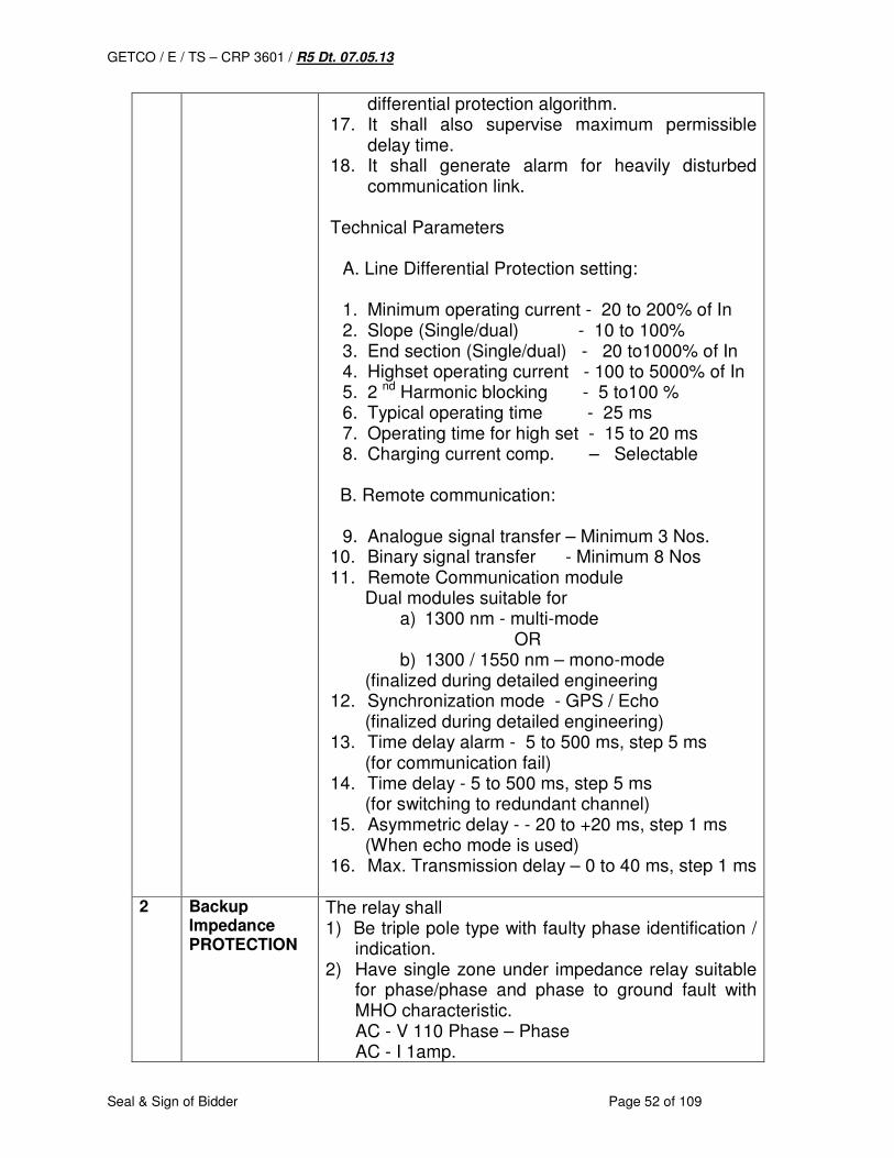
GETCO / E / TS – CRP 3601 / R5 Dt. 07.05.13
Seal & Sign of Bidder Page 52 of 109
differential protection algorithm. 17. It shall also supervise maximum permissible
delay time. 18. It shall generate alarm for heavily disturbed
communication link. Technical Parameters
A. Line Differential Protection setting: 1. Minimum operating current - 20 to 200% of In 2. Slope (Single/dual) - 10 to 100% 3. End section (Single/dual) - 20 to1000% of In 4. Highset operating current - 100 to 5000% of In 5. 2 nd Harmonic blocking - 5 to100 % 6. Typical operating time - 25 ms 7. Operating time for high set - 15 to 20 ms 8. Charging current comp. – Selectable
B. Remote communication:
9. Analogue signal transfer – Minimum 3 Nos. 10. Binary signal transfer - Minimum 8 Nos 11. Remote Communication module Dual modules suitable for
a) 1300 nm - multi-mode OR b) 1300 / 1550 nm – mono-mode
(finalized during detailed engineering 12. Synchronization mode - GPS / Echo (finalized during detailed engineering) 13. Time delay alarm - 5 to 500 ms, step 5 ms (for communication fail) 14. Time delay - 5 to 500 ms, step 5 ms (for switching to redundant channel) 15. Asymmetric delay - - 20 to +20 ms, step 1 ms (When echo mode is used) 16. Max. Transmission delay – 0 to 40 ms, step 1 ms
2 Backup
Impedance PROTECTION
The relay shall 1) Be triple pole type with faulty phase identification /
indication. 2) Have single zone under impedance relay suitable
for phase/phase and phase to ground fault with MHO characteristic.
AC - V 110 Phase – Phase AC - I 1amp.
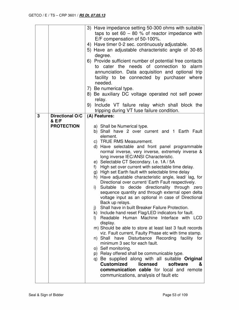
GETCO / E / TS – CRP 3601 / R5 Dt. 07.05.13
Seal & Sign of Bidder Page 53 of 109
3) Have impedance setting 50-300 ohms with suitable taps to set 60 – 80 % of reactor impedance with E/F compensation of 50-100%.
4) Have timer 0-2 sec. continuously adjustable. 5) Have an adjustable characteristic angle of 30-85
degree. 6) Provide sufficient number of potential free contacts
to cater the needs of connection to alarm annunciation. Data acquisition and optional trip facility to be connected by purchaser where needed.
7) Be numerical type. 8) Be auxiliary DC voltage operated not self power
relay. 9) Include VT failure relay which shall block the
tripping during VT fuse failure condition. 3 Directional O/C
& E/F PROTECTION
(A) Features:
a) Shall be Numerical type. b) Shall have 2 over current and 1 Earth Fault
element. c) TRUE RMS Measurement. d) Have selectable and front panel programmable
normal inverse, very inverse, extremely inverse & long inverse IEC/ANSI Characteristic.
e) Selectable CT Secondary. I.e. 1A / 5A f) High set over current with selectable time delay. g) High set Earth fault with selectable time delay h) Have adjustable characteristic angle, lead/ lag, for
Directional over current/ Earth Fault respectively. i) Suitable to decide directionality through zero
sequence quantity and through external open delta voltage input as an optional in case of Directional Back up relays.
j) Shall have in built Breaker Failure Protection. k) Include hand reset Flag/LED indicators for fault. l) Readable Human Machine Interface with LCD
display. m) Should be able to store at least last 3 fault records
viz. Fault current, Faulty Phase etc with time stamp. n) Shall have Disturbance Recording facility for
minimum 3 sec for each fault. o) Self monitoring. p) Relay offered shall be communicable type.
q) Be supplied along with all suitable Original Customized licensed software & communication cable for local and remote communications, analysis of fault etc
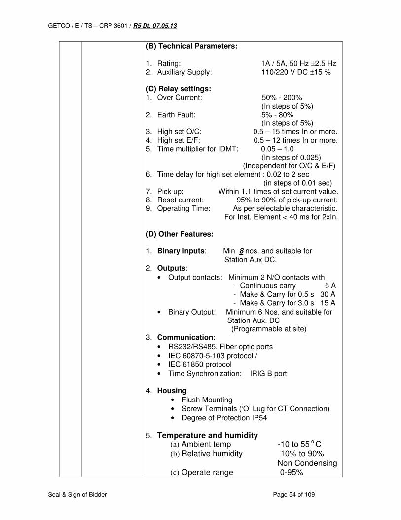
GETCO / E / TS – CRP 3601 / R5 Dt. 07.05.13
Seal & Sign of Bidder Page 54 of 109
(B) Technical Parameters: 1. Rating: 1A / 5A, 50 Hz ±2.5 Hz 2. Auxiliary Supply: 110/220 V DC ±15 % (C) Relay settings: 1. Over Current: 50% - 200% (In steps of 5%) 2. Earth Fault: 5% - 80% (In steps of 5%) 3. High set O/C: 0.5 – 15 times In or more. 4. High set E/F: 0.5 – 12 times In or more. 5. Time multiplier for IDMT: 0.05 – 1.0 (In steps of 0.025) (Independent for O/C & E/F) 6. Time delay for high set element : 0.02 to 2 sec (in steps of 0.01 sec) 7. Pick up: Within 1.1 times of set current value. 8. Reset current: 95% to 90% of pick-up current. 9. Operating Time: As per selectable characteristic. For Inst. Element < 40 ms for 2xIn. (D) Other Features: 1. Binary inputs: Min 8 nos. and suitable for Station Aux DC. 2. Outputs:
• Output contacts: Minimum 2 N/O contacts with - Continuous carry 5 A - Make & Carry for 0.5 s 30 A - Make & Carry for 3.0 s 15 A
• Binary Output: Minimum 6 Nos. and suitable for Station Aux. DC (Programmable at site)
3. Communication:
• RS232/RS485, Fiber optic ports
• IEC 60870-5-103 protocol /
• IEC 61850 protocol
• Time Synchronization: IRIG B port 4. Housing
• Flush Mounting
• Screw Terminals (‘O’ Lug for CT Connection)
• Degree of Protection IP54
5. Temperature and humidity
(a) Ambient temp -10 to 55 o C (b) Relative humidity 10% to 90% Non Condensing (c) Operate range 0-95%
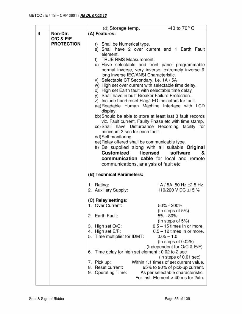
GETCO / E / TS – CRP 3601 / R5 Dt. 07.05.13
Seal & Sign of Bidder Page 55 of 109
(d) Storage temp. -40 to 70 o C 4 Non-Dir.
O/C & E/F PROTECTION
(A) Features:
r) Shall be Numerical type. s) Shall have 2 over current and 1 Earth Fault
element. t) TRUE RMS Measurement. u) Have selectable and front panel programmable
normal inverse, very inverse, extremely inverse & long inverse IEC/ANSI Characteristic.
v) Selectable CT Secondary. I.e. 1A / 5A w) High set over current with selectable time delay. x) High set Earth fault with selectable time delay y) Shall have in built Breaker Failure Protection. z) Include hand reset Flag/LED indicators for fault. aa) Readable Human Machine Interface with LCD
display. bb) Should be able to store at least last 3 fault records
viz. Fault current, Faulty Phase etc with time stamp. cc) Shall have Disturbance Recording facility for
minimum 3 sec for each fault. dd) Self monitoring. ee) Relay offered shall be communicable type.
ff) Be supplied along with all suitable Original Customized licensed software & communication cable for local and remote communications, analysis of fault etc
(B) Technical Parameters: 1. Rating: 1A / 5A, 50 Hz ±2.5 Hz 2. Auxiliary Supply: 110/220 V DC ±15 % (C) Relay settings: 1. Over Current: 50% - 200% (In steps of 5%) 2. Earth Fault: 5% - 80% (In steps of 5%) 3. High set O/C: 0.5 – 15 times In or more. 4. High set E/F: 0.5 – 12 times In or more. 5. Time multiplier for IDMT: 0.05 – 1.0 (In steps of 0.025) (Independent for O/C & E/F) 6. Time delay for high set element : 0.02 to 2 sec (in steps of 0.01 sec) 7. Pick up: Within 1.1 times of set current value. 8. Reset current: 95% to 90% of pick-up current. 9. Operating Time: As per selectable characteristic. For Inst. Element < 40 ms for 2xIn.
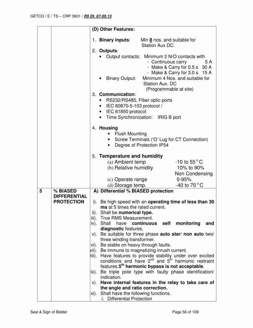
GETCO / E / TS – CRP 3601 / R5 Dt. 07.05.13
Seal & Sign of Bidder Page 56 of 109
(D) Other Features: 1. Binary inputs: Min 8 nos. and suitable for Station Aux DC. 2. Outputs:
• Output contacts: Minimum 2 N/O contacts with - Continuous carry 5 A - Make & Carry for 0.5 s 30 A - Make & Carry for 3.0 s 15 A
• Binary Output: Minimum 4 Nos. and suitable for Station Aux. DC (Programmable at site)
3. Communication:
• RS232/RS485, Fiber optic ports
• IEC 60870-5-103 protocol /
• IEC 61850 protocol
• Time Synchronization: IRIG B port 4. Housing
• Flush Mounting
• Screw Terminals (‘O’ Lug for CT Connection)
• Degree of Protection IP54
5. Temperature and humidity
(a) Ambient temp -10 to 55 o C (b) Relative humidity 10% to 90% Non Condensing (c) Operate range 0-95% (d) Storage temp. -40 to 70 o C
5 % BIASED DIFFERENTIAL PROTECTION
A) Differential % BIASED protection
i). Be high speed with an operating time of less than 30 ms at 5 times the rated current.
ii). Shall be numerical type. iii). True RMS Measurement. iv). Shall have continuous self monitoring and
diagnostic features. v). Be suitable for three phase auto star/ non auto two/
three winding transformer. vi). Be stable on heavy through faults. vii). Be immune to magnetizing inrush current. viii). Have features to provide stability under over excited
conditions and have 2nd and 5th harmonic restraint features.5th harmonic bypass is not acceptable.
ix). Be triple pole type with faulty phase identification/ indication.
x). Have internal features in the relay to take care of the angle and ratio correction.
xi). Shall have the following functions. i. Differential Protection

GETCO / E / TS – CRP 3601 / R5 Dt. 07.05.13
Seal & Sign of Bidder Page 57 of 109
ii. Restricted Earth Fault Protection iii. Thermal Over Load Detection iv. Over Fluxing Protection v. LBB
xii). Provide sufficient number of potential free contacts to cater the needs of connection to alarm annunciation. Data acquisition and optional trip facility to be connected by purchaser where needed.
xiii). Be supplied along with all suitable Original Customized licensed software & communication cable for local and remote communications, analysis of fault etc.
xiv). Have a local user interface (MMI) comprising of a 2-3 line alphanumeric LCD display and a soft touch key pad to access the settings, events and records in the relay.
xv). Have a front RS 232 communication ports for use with a PC locally for local access to settings, events and recorders.
xvi). Have two rear communication ports on fiber optic/twisted wires for remote communication based on RS 485 connectivity to support (1) all the facilities available via the integral user interface and (2) facilities supplied under IEC – 61850 interface.
xvii). Have a disturbance recording feature to record graphic form of instantaneous values of current in all three windings in nine analog channels during faults and disturbances for the pre fault and post fault period. The disturbance recorder shall have the facility to record the following external digital channel signals apart from the digital signals pertaining to differential relays.
a. REF protection operated b. HV Each Breaker pole status i.e. 3 no.
inputs c. LV Each Breaker pole status i.e. 3 no. inputs. d. Buchholz / OLTC Buchholz alarm / trip i.e. 4
no. inputs. e. WTI/OTI/PRV alarm /trip of transformer.
Necessary hardware and software for down loading the data captured by disturbance recorder to the personal computer available in the sub station shall be included in the scope.
B) OVER FLUX FEATURE i). Operate on the principle of voltage to frequency ratio
and shall be phase to phase connected. ii). Have inverse time characteristics, matching with
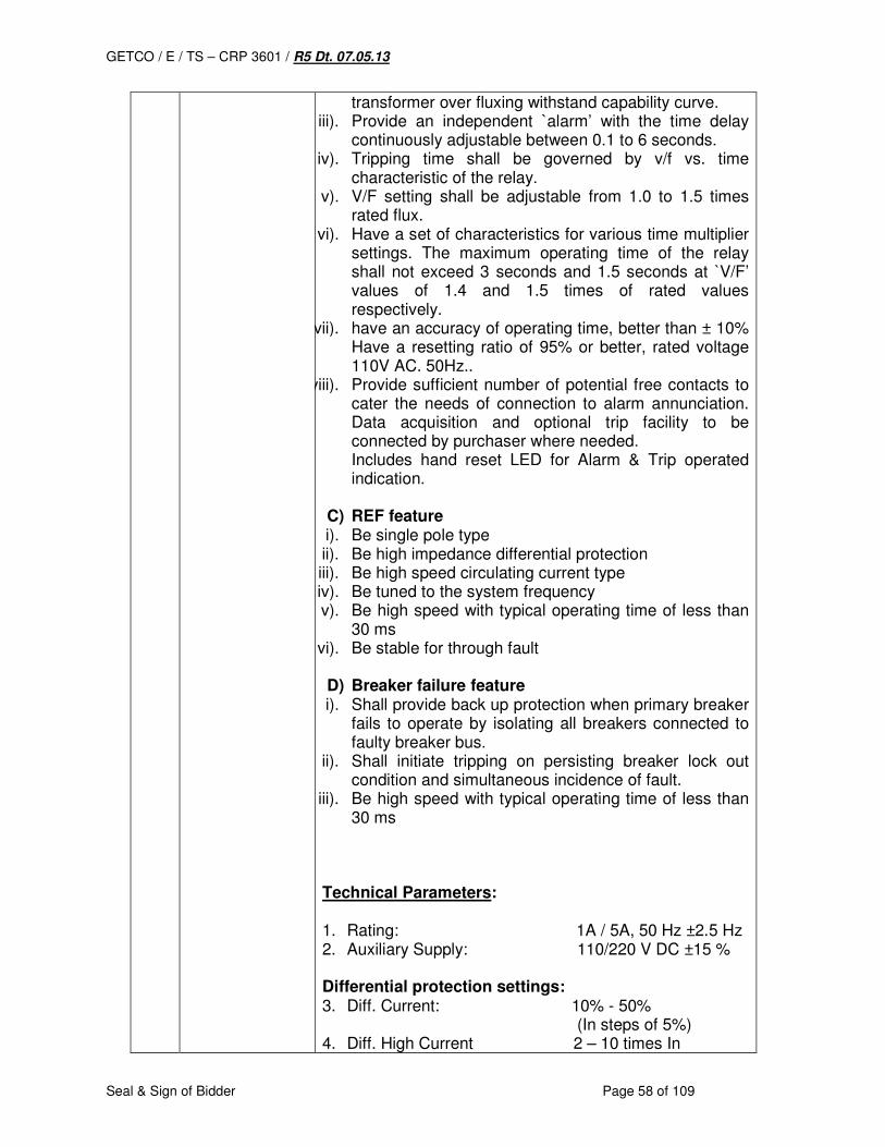
GETCO / E / TS – CRP 3601 / R5 Dt. 07.05.13
Seal & Sign of Bidder Page 58 of 109
transformer over fluxing withstand capability curve. iii). Provide an independent `alarm’ with the time delay
continuously adjustable between 0.1 to 6 seconds. iv). Tripping time shall be governed by v/f vs. time
characteristic of the relay. v). V/F setting shall be adjustable from 1.0 to 1.5 times
rated flux. vi). Have a set of characteristics for various time multiplier
settings. The maximum operating time of the relay shall not exceed 3 seconds and 1.5 seconds at `V/F’ values of 1.4 and 1.5 times of rated values respectively.
vii). have an accuracy of operating time, better than ± 10% Have a resetting ratio of 95% or better, rated voltage 110V AC. 50Hz..
viii). Provide sufficient number of potential free contacts to cater the needs of connection to alarm annunciation. Data acquisition and optional trip facility to be connected by purchaser where needed. Includes hand reset LED for Alarm & Trip operated indication.
C) REF feature i). Be single pole type ii). Be high impedance differential protection iii). Be high speed circulating current type iv). Be tuned to the system frequency v). Be high speed with typical operating time of less than
30 ms vi). Be stable for through fault
D) Breaker failure feature i). Shall provide back up protection when primary breaker
fails to operate by isolating all breakers connected to faulty breaker bus.
ii). Shall initiate tripping on persisting breaker lock out condition and simultaneous incidence of fault.
iii). Be high speed with typical operating time of less than 30 ms
Technical Parameters: 1. Rating: 1A / 5A, 50 Hz ±2.5 Hz 2. Auxiliary Supply: 110/220 V DC ±15 % Differential protection settings: 3. Diff. Current: 10% - 50% (In steps of 5%) 4. Diff. High Current 2 – 10 times In
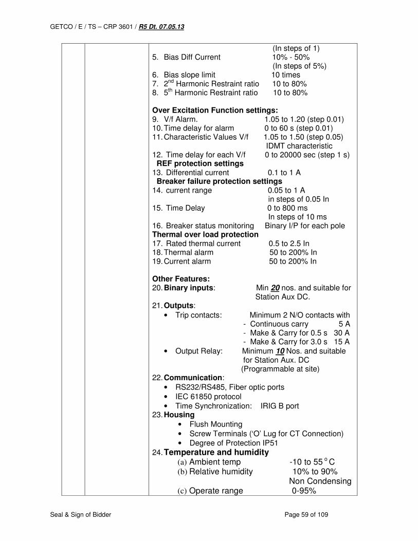
GETCO / E / TS – CRP 3601 / R5 Dt. 07.05.13
Seal & Sign of Bidder Page 59 of 109
(In steps of 1) 5. Bias Diff Current 10% - 50% (In steps of 5%) 6. Bias slope limit 10 times 7. 2nd Harmonic Restraint ratio 10 to 80% 8. 5th Harmonic Restraint ratio 10 to 80% Over Excitation Function settings: 9. V/f Alarm. 1.05 to 1.20 (step 0.01) 10. Time delay for alarm 0 to 60 s (step 0.01) 11. Characteristic Values V/f 1.05 to 1.50 (step 0.05) IDMT characteristic 12. Time delay for each V/f 0 to 20000 sec (step 1 s) REF protection settings 13. Differential current 0.1 to 1 A Breaker failure protection settings 14. current range 0.05 to 1 A in steps of 0.05 In 15. Time Delay 0 to 800 ms In steps of 10 ms 16. Breaker status monitoring Binary I/P for each pole Thermal over load protection 17. Rated thermal current 0.5 to 2.5 In 18. Thermal alarm 50 to 200% In 19. Current alarm 50 to 200% In Other Features: 20. Binary inputs: Min 20 nos. and suitable for Station Aux DC. 21. Outputs:
• Trip contacts: Minimum 2 N/O contacts with - Continuous carry 5 A - Make & Carry for 0.5 s 30 A - Make & Carry for 3.0 s 15 A • Output Relay: Minimum 10 Nos. and suitable for Station Aux. DC (Programmable at site)
22. Communication:
• RS232/RS485, Fiber optic ports
• IEC 61850 protocol
• Time Synchronization: IRIG B port 23. Housing
• Flush Mounting
• Screw Terminals (‘O’ Lug for CT Connection)
• Degree of Protection IP51
24. Temperature and humidity
(a) Ambient temp -10 to 55 o C (b) Relative humidity 10% to 90% Non Condensing (c) Operate range 0-95%
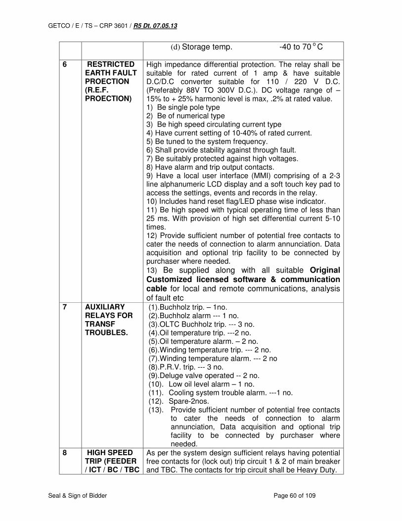
GETCO / E / TS – CRP 3601 / R5 Dt. 07.05.13
Seal & Sign of Bidder Page 60 of 109
(d) Storage temp. -40 to 70 o C
6 RESTRICTED EARTH FAULT PROECTION (R.E.F. PROECTION)
High impedance differential protection. The relay shall be suitable for rated current of 1 amp & have suitable D.C/D.C converter suitable for 110 / 220 V D.C. (Preferably 88V TO 300V D.C.). DC voltage range of – 15% to + 25% harmonic level is max, .2% at rated value. 1) Be single pole type 2) Be of numerical type 3) Be high speed circulating current type 4) Have current setting of 10-40% of rated current. 5) Be tuned to the system frequency. 6) Shall provide stability against through fault. 7) Be suitably protected against high voltages. 8) Have alarm and trip output contacts. 9) Have a local user interface (MMI) comprising of a 2-3 line alphanumeric LCD display and a soft touch key pad to access the settings, events and records in the relay. 10) Includes hand reset flag/LED phase wise indicator. 11) Be high speed with typical operating time of less than 25 ms. With provision of high set differential current 5-10 times. 12) Provide sufficient number of potential free contacts to cater the needs of connection to alarm annunciation. Data acquisition and optional trip facility to be connected by purchaser where needed.
13) Be supplied along with all suitable Original Customized licensed software & communication cable for local and remote communications, analysis of fault etc
7 AUXILIARY RELAYS FOR TRANSF TROUBLES.
(1).Buchholz trip. – 1no. (2).Buchholz alarm --- 1 no. (3).OLTC Buchholz trip. --- 3 no. (4).Oil temperature trip. ---2 no. (5).Oil temperature alarm. – 2 no. (6).Winding temperature trip. --- 2 no. (7).Winding temperature alarm. --- 2 no (8).P.R.V. trip. --- 3 no. (9).Deluge valve operated -- 2 no. (10). Low oil level alarm – 1 no. (11). Cooling system trouble alarm. ---1 no. (12). Spare-2nos. (13). Provide sufficient number of potential free contacts
to cater the needs of connection to alarm annunciation, Data acquisition and optional trip facility to be connected by purchaser where needed.
8 HIGH SPEED TRIP (FEEDER / ICT / BC / TBC
As per the system design sufficient relays having potential free contacts for (lock out) trip circuit 1 & 2 of main breaker and TBC. The contacts for trip circuit shall be Heavy Duty.
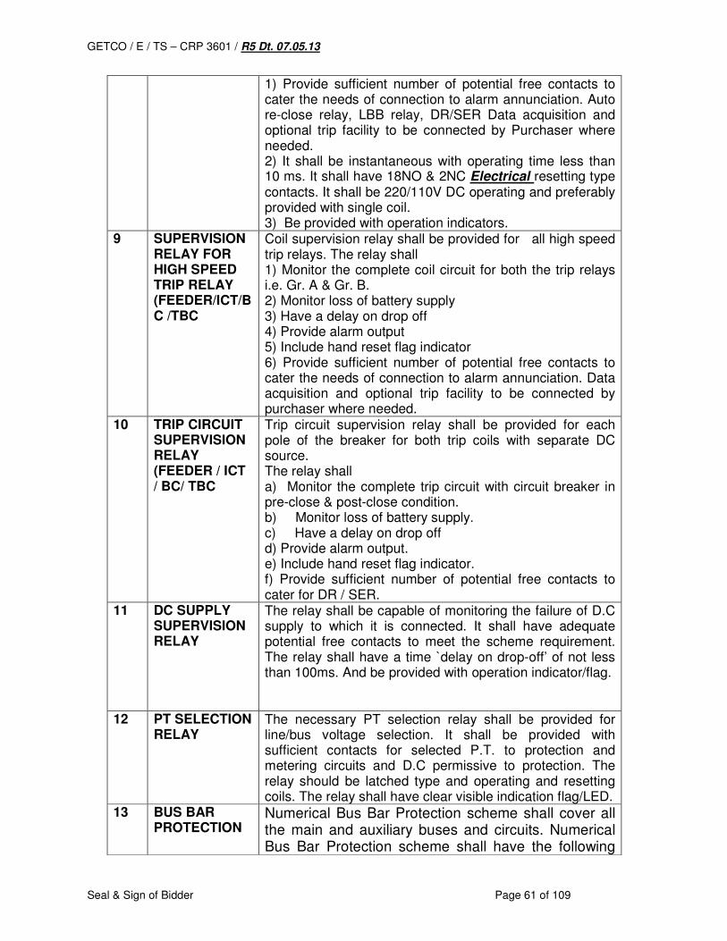
GETCO / E / TS – CRP 3601 / R5 Dt. 07.05.13
Seal & Sign of Bidder Page 61 of 109
1) Provide sufficient number of potential free contacts to cater the needs of connection to alarm annunciation. Auto re-close relay, LBB relay, DR/SER Data acquisition and optional trip facility to be connected by Purchaser where needed. 2) It shall be instantaneous with operating time less than 10 ms. It shall have 18NO & 2NC Electrical resetting type contacts. It shall be 220/110V DC operating and preferably provided with single coil. 3) Be provided with operation indicators.
9 SUPERVISION RELAY FOR HIGH SPEED TRIP RELAY (FEEDER/ICT/BC /TBC
Coil supervision relay shall be provided for all high speed trip relays. The relay shall 1) Monitor the complete coil circuit for both the trip relays i.e. Gr. A & Gr. B. 2) Monitor loss of battery supply 3) Have a delay on drop off 4) Provide alarm output 5) Include hand reset flag indicator 6) Provide sufficient number of potential free contacts to cater the needs of connection to alarm annunciation. Data acquisition and optional trip facility to be connected by purchaser where needed.
10 TRIP CIRCUIT SUPERVISION RELAY (FEEDER / ICT / BC/ TBC
Trip circuit supervision relay shall be provided for each pole of the breaker for both trip coils with separate DC source. The relay shall a) Monitor the complete trip circuit with circuit breaker in pre-close & post-close condition. b) Monitor loss of battery supply. c) Have a delay on drop off d) Provide alarm output. e) Include hand reset flag indicator. f) Provide sufficient number of potential free contacts to cater for DR / SER.
11 DC SUPPLY SUPERVISION RELAY
The relay shall be capable of monitoring the failure of D.C supply to which it is connected. It shall have adequate potential free contacts to meet the scheme requirement. The relay shall have a time `delay on drop-off’ of not less than 100ms. And be provided with operation indicator/flag.
12 PT SELECTION RELAY
The necessary PT selection relay shall be provided for line/bus voltage selection. It shall be provided with sufficient contacts for selected P.T. to protection and metering circuits and D.C permissive to protection. The relay should be latched type and operating and resetting coils. The relay shall have clear visible indication flag/LED.
13 BUS BAR PROTECTION
Numerical Bus Bar Protection scheme shall cover all the main and auxiliary buses and circuits. Numerical Bus Bar Protection scheme shall have the following
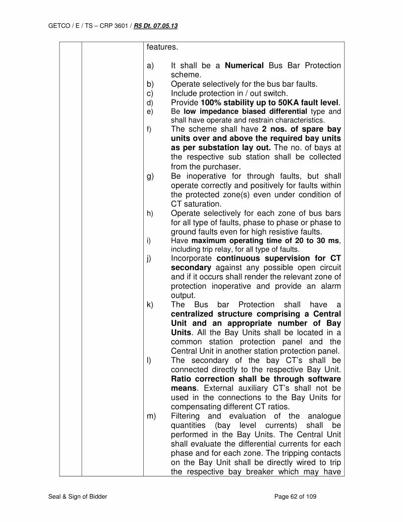
GETCO / E / TS – CRP 3601 / R5 Dt. 07.05.13
Seal & Sign of Bidder Page 62 of 109
features. a) It shall be a Numerical Bus Bar Protection
scheme. b) Operate selectively for the bus bar faults. c) Include protection in / out switch. d) Provide 100% stability up to 50KA fault level. e) Be low impedance biased differential type and
shall have operate and restrain characteristics.
f) The scheme shall have 2 nos. of spare bay units over and above the required bay units as per substation lay out. The no. of bays at the respective sub station shall be collected
from the purchaser. g) Be inoperative for through faults, but shall
operate correctly and positively for faults within the protected zone(s) even under condition of CT saturation.
h) Operate selectively for each zone of bus bars for all type of faults, phase to phase or phase to ground faults even for high resistive faults.
i) Have maximum operating time of 20 to 30 ms, including trip relay, for all type of faults.
j) Incorporate continuous supervision for CT secondary against any possible open circuit and if it occurs shall render the relevant zone of protection inoperative and provide an alarm output.
k) The Bus bar Protection shall have a centralized structure comprising a Central Unit and an appropriate number of Bay Units. All the Bay Units shall be located in a common station protection panel and the Central Unit in another station protection panel.
l) The secondary of the bay CT’s shall be connected directly to the respective Bay Unit. Ratio correction shall be through software means. External auxiliary CT’s shall not be used in the connections to the Bay Units for compensating different CT ratios.
m) Filtering and evaluation of the analogue quantities (bay level currents) shall be performed in the Bay Units. The Central Unit shall evaluate the differential currents for each phase and for each zone. The tripping contacts on the Bay Unit shall be directly wired to trip the respective bay breaker which may have
GETCO / E / TS – CRP 3601 / R5 Dt. 07.05.13
Seal & Sign of Bidder Page 63 of 109
one or two trip coils. The contacts should be of adequate rating.
n) The Bay Units shall be connected to the Central unit by means of fiber optic cables. The communication between the Bay Units and the Central Unit shall be effected by means of a deterministic protocol. In case of any interruption in the communication between the Central Unit and any Bay Unit, the corresponding zone shall be blocked. An alarm shall also be given.
o) The normally open and normally closed auxiliary contacts of the isolators of each bay shall be connected to the respective Bay Unit. The Bay Units shall send the information regarding the positions of the isolators to the Central Unit at regular intervals and the image of the bus bar shall be formed in software form in the Central Unit. External relays shall not be used for forming the image of the bus bar.
p) The normally open (NO) and normally closed (NC) auxiliary contacts on each isolator shall be used for selection of bus bar zones.
q) No CT switching relays shall be used for connecting correct CT inputs to the protected zone. If both isolators of a particular bay are closed, an audible isolator alarm shall be given and the bus bar zones should act as single zone. This monitoring of the integrity of the isolator auxiliary contacts shall be performed in software form without the use of external relays and timers.
r) To enhance security, the Bus bar Protection scheme shall have two independent measurement and tripping criteria. A trip signal shall be initiated only if both criteria are simultaneously satisfied. Neither criterion shall be voltage dependent.
s) Preferably, these two criteria shall be the stabilized differential current and the phase (directional) comparison of currents in the different bays.
t) The Bus bar Protection shall be insensitive to transients and harmonics and be fully reliable and selective even under CT saturation conditions.
u) The Bus bar Protection shall be capable of

GETCO / E / TS – CRP 3601 / R5 Dt. 07.05.13
Seal & Sign of Bidder Page 64 of 109
operating with CT’s of widely different ratios with different rated secondary currents. The matching of CT ratio in each bay shall be done by a simple setting via the HMI without the use of external auxiliary CT’s.
v) The numerical bus bar protection shall be with extensive self-supervision and diagnostic facilities.
w) The HMI program should graphically display the bus bar configuration and the bus bar image. The HMI program shall facilitate setting of the protection and read out of various information such as bus differential current in each zone, phase currents (and voltages in each bay), positions of the isolators & breakers, etc. The HMI program shall also permit dialogue with the protection from a remote location without the need for additional software. The HMI program should be based on MS Windows environment.
x) The HMI program shall facilitate free assignment of the optocoupler inputs and signal relay / trip relay outputs to a given list of inputs and outputs. It shall be possible to program the output relays to be of the latched or non-latched type.
y) The redundant features available shall include redundant power supply module for the Bay Units & the Central Unit and a second input/output card for the Central Unit.
z) The system shall, preferably, as options, permit inclusion of additional functions such as independent Over current Protection at the bay level, trip re-direction, pole discrepancy detection and where required, under voltage/ over current release for Bus bar Protection.
aa) The Bus bar Protection shall include a Disturbance Recorder function in each Bay Unit which shall record the bay phase currents. The sampling frequency of this Disturbance Recorder function shall be selectable from 2400 Hz, 1200 Hz or 600 Hz. The recording period shall be at least 1.5 seconds. The system shall, preferably, as an option, permit recording of bay level voltages as well.
bb) The Bus bar Protection shall also include an Event Recorder function. The Event Record
GETCO / E / TS – CRP 3601 / R5 Dt. 07.05.13
Seal & Sign of Bidder Page 65 of 109
buffer in the Central Unit shall accommodate at least 1000 events while that in each Bay Unit shall accommodate at least 100 events.
cc) The Disturbance Recorder and Event Recorder buffer memory shall be of non-volatile type and shall not require the use of batteries.
dd) When the bus tie breaker is equipped with one set of CT’s only and when the bus tie breaker is in open position, the Bus bar Protection shall exclude this CT in the evaluation of the Bus bar Protection measurement. This will ensure that, when the bus tie breaker is in open position and a fault occurs between the CT and the bus tie breaker, the faulted bus section is selectively tripped and isolated without any delay. The healthy bus section will not be tripped.
ee) A Local Display Unit (LDU) shall be provided on the Central Unit and on each Bay Unit.
ff) The LDU on the Central Unit shall permit read out of the following information:
• Differential currents in each Bus bar zone and each phase
• Alarm conditions
• Trip conditions
• State of all the inputs and outputs in the Central Unit
• Setting values
• Phase currents (and optionally, phase voltages) in each bay
• State of all the inputs and outputs in each bay
• Positions of the isolators in each bay
• Positions of the breakers in each bay
• Setting values
• Resetting of output relays gg) The LDU on each Bay Unit shall permit read
out of the following information:
• Phase currents (and optionally, phase voltages) in each bay
• Alarm conditions
• Trip conditions
• State of all the inputs and outputs in the respective bay
• Positions of the isolators in the respective bay
GETCO / E / TS – CRP 3601 / R5 Dt. 07.05.13
Seal & Sign of Bidder Page 66 of 109
• Position of the breaker in the respective bay
• Setting values
• Resetting of output relays hh) Provide sufficient number of potential free
contacts to cater the needs of connection to alarm annunciation. Data acquisition and optional trip facility to be connected by purchaser where needed.
ii) Shall have immunity against system transients. jj) Include continuous DC supply supervision. kk) Incorporate clear zone indication. ll) Should not operate during the change over
operation of a circuit from one bus to another bus and during normal load flow in bus bars.
mm) Trip both the breakers i.e. the breakers being bypassed and the transfer breaker if the bus fault occurs during the change over operation.
nn) Have provision to reset trip bus through a single push button to be provided for the purpose.
oo) It shall be possible to prepare the Bus bar Protection to include, in the protection scheme, future bays as and when they are added. In such cases, the system shall be easily extendable by adding Bay Units for the new bays and activating the same in the Bus bar Protection. Such extension work shall not require any other wiring changes to the existing system.
pp) The bus bar protection offered shall have communication port for integrating with the local station automation or to a station monitoring system. One of the protocols offered for the communication port shall be an international standard protocol IEC 61850.
qq) Be supplied along with all suitable Original Customized licensed software & communication cable for local and remote communications, analysis of fault etc
rr) The bay unit shall have built-in Breaker Failure feature
Rated Parameters: Bus Bar Protection Functions: 1. Min fault current pick-up: 500 to 6000 A
GETCO / E / TS – CRP 3601 / R5 Dt. 07.05.13
Seal & Sign of Bidder Page 67 of 109
(Ikmin) In steps of 100 A 2. Neutral current Detection: 100 to 6000 A 3. Stabilizing factor (K): 0.7 to 0.9 in steps of 0.05 4. Diff current Alarm: 5 to 50% of Ikmin 2 to 10 s Time Delay 5. Isolator alarm time delay: 0.5 to 90 s 6. Typical tripping time: 20 to 30 ms 7. CT ratio per feeder: 50 to 10000/1 A Analog Inputs (Bay or Peripheral or Field Unit): 1. No. of Bays: Bays at respective s/s + 2 2. Current Rating: 1A, 50 Hz ±2.5 Hz, ≤0.2 VA 3. Thermal Ratings:
• Continuous 4xIn
• For 10 s Minimum 10xIn
• For 1 s 100xIn 5. Voltage Rating: 110 V, 50 Hz, ≤ 0.3 VA at Un 6. Auxiliary Supply: 48 to 250 V DC ±15 %, 11 W Binary Inputs/ Outputs: 1. Operating Time: 3 ms 2. Max Operating Volt: 24 to 250 V DC 3. Max Cont rating: ≤ 8 A 4. Max make & Carry: ≤ 30 A (0.5 s) 5. Max making power: ≤ 3300 W ( at 110 V DC) 6. Binary O/P Reset: Programmable 7. Breaking Current: Heavy Duty N/O Contact: ≤ 0.3 A Signaling Contact: ≤ 0.1 A 8. No. of I/P per bay unit: 20 Opto-couplers 9. No. of I/P for central unit: 12 Opto-couplers 10. Pickup current for I/P: ≥ 10 mA 11. Operating Time for I/P: < 1 s Auxiliary Supply: 1. Input Voltage: 220/110 V DC, ± 20 % 2. Load: 10 W (Bay Unit) 100 W (Central Unit) 3. Front plate Signal: green LED 4. Switch: ON/ OFF 5. Redundancy of Power Supply: Optional Optical Interface: 1. Number of Cores: 2 fiber cores per bay unit 2. Core/ sheath diameter: 62.5/ 125 µm (multi-mode) 3. Max permissible attenuation: ≤ 5 db 4. Connector: Type FST for 62.5 µm OFC
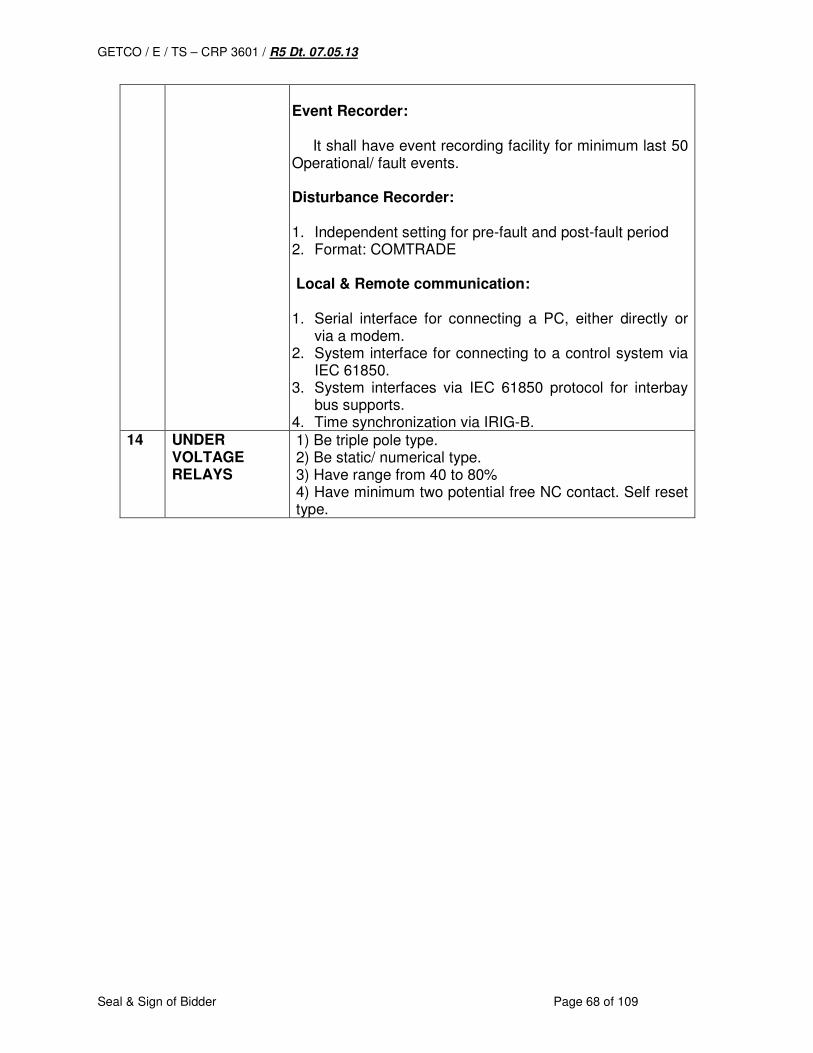
GETCO / E / TS – CRP 3601 / R5 Dt. 07.05.13
Seal & Sign of Bidder Page 68 of 109
Event Recorder: It shall have event recording facility for minimum last 50 Operational/ fault events. Disturbance Recorder: 1. Independent setting for pre-fault and post-fault period 2. Format: COMTRADE Local & Remote communication: 1. Serial interface for connecting a PC, either directly or
via a modem. 2. System interface for connecting to a control system via
IEC 61850. 3. System interfaces via IEC 61850 protocol for interbay
bus supports. 4. Time synchronization via IRIG-B.
14 UNDER VOLTAGE RELAYS
1) Be triple pole type. 2) Be static/ numerical type. 3) Have range from 40 to 80% 4) Have minimum two potential free NC contact. Self reset type.
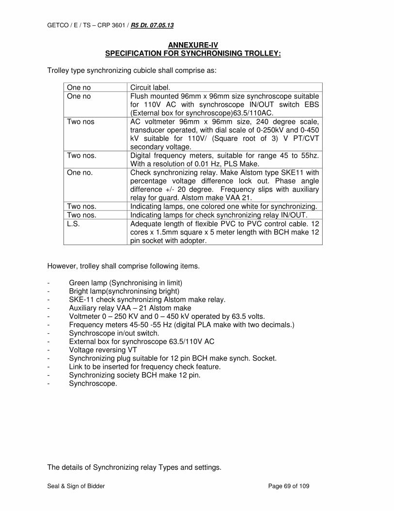
GETCO / E / TS – CRP 3601 / R5 Dt. 07.05.13
Seal & Sign of Bidder Page 69 of 109
ANNEXURE-IV SPECIFICATION FOR SYNCHRONISING TROLLEY:
Trolley type synchronizing cubicle shall comprise as:
One no Circuit label. One no Flush mounted 96mm x 96mm size synchroscope suitable
for 110V AC with synchroscope IN/OUT switch EBS (External box for synchroscope)63.5/110AC.
Two nos AC voltmeter 96mm x 96mm size, 240 degree scale, transducer operated, with dial scale of 0-250kV and 0-450 kV suitable for 110V/ (Square root of 3) V PT/CVT secondary voltage.
Two nos. Digital frequency meters, suitable for range 45 to 55hz. With a resolution of 0.01 Hz, PLS Make.
One no. Check synchronizing relay. Make Alstom type SKE11 with percentage voltage difference lock out. Phase angle difference +/- 20 degree. Frequency slips with auxiliary relay for guard. Alstom make VAA 21.
Two nos. Indicating lamps, one colored one white for synchronizing. Two nos. Indicating lamps for check synchronizing relay IN/OUT. L.S. Adequate length of flexible PVC to PVC control cable. 12
cores x 1.5mm square x 5 meter length with BCH make 12 pin socket with adopter.
However, trolley shall comprise following items. - Green lamp (Synchronising in limit) - Bright lamp(synchroninsing bright) - SKE-11 check synchronizing Alstom make relay. - Auxiliary relay VAA – 21 Alstom make - Voltmeter 0 – 250 KV and 0 – 450 kV operated by 63.5 volts. - Frequency meters 45-50 -55 Hz (digital PLA make with two decimals.) - Synchroscope in/out switch. - External box for synchroscope 63.5/110V AC - Voltage reversing VT - Synchronizing plug suitable for 12 pin BCH make synch. Socket. - Link to be inserted for frequency check feature. - Synchronizing society BCH make 12 pin. - Synchroscope. The details of Synchronizing relay Types and settings.
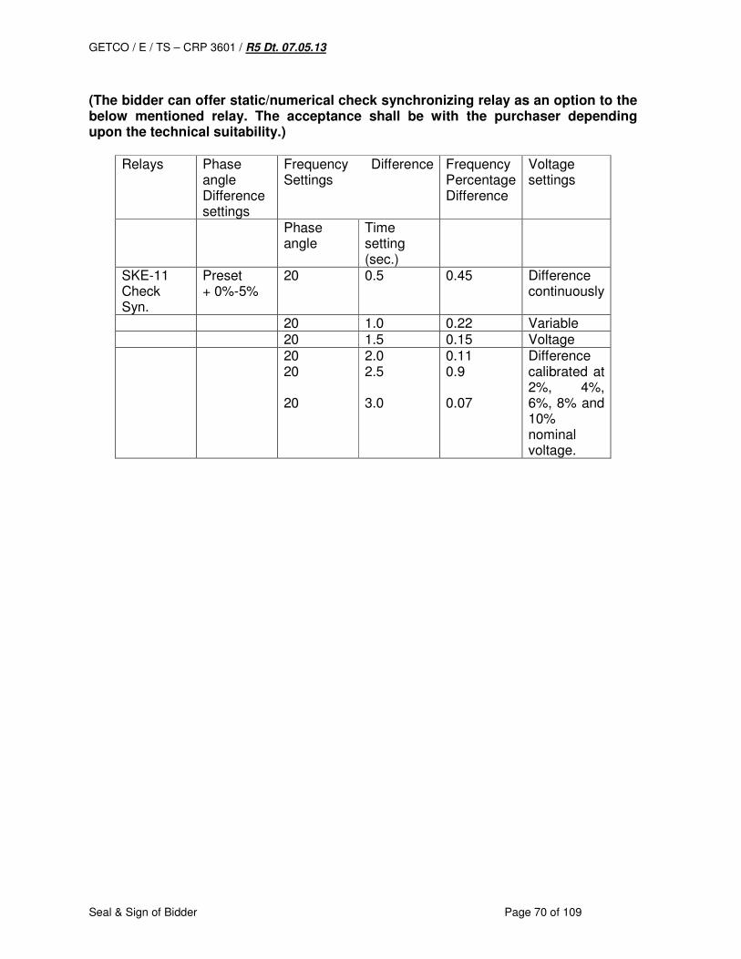
GETCO / E / TS – CRP 3601 / R5 Dt. 07.05.13
Seal & Sign of Bidder Page 70 of 109
(The bidder can offer static/numerical check synchronizing relay as an option to the below mentioned relay. The acceptance shall be with the purchaser depending upon the technical suitability.)
Relays Phase angle Difference settings
Frequency Difference Settings
Frequency Percentage Difference
Voltage settings
Phase angle
Time setting (sec.)
SKE-11 Check Syn.
Preset + 0%-5%
20 0.5 0.45 Difference continuously
20 1.0 0.22 Variable 20 1.5 0.15 Voltage 20
20 20
2.0 2.5 3.0
0.11 0.9 0.07
Difference calibrated at 2%, 4%, 6%, 8% and 10% nominal voltage.
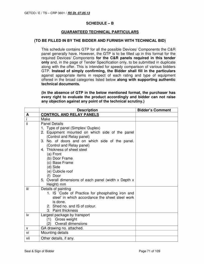
GETCO / E / TS – CRP 3601 / R5 Dt. 07.05.13
Seal & Sign of Bidder Page 71 of 109
SCHEDULE – B
GUARANTEED TECHNICAL PARTICULARS
(TO BE FILLED IN BY THE BIDDER AND FURNISH WITH TECHNICAL BID) This schedule contains GTP for all the possible Devices/ Components the C&R panel generally have. However, the GTP is to be filled up in this format for the required Devices/ Components for the C&R panels required in this tender only and, in the page of Tender Specification only, to be submitted in duplicate along with the offer. This is intended for speedy comparison of various bidders GTP. Instead of simply confirming, the Bidder shall fill in the particulars against appropriate items in respect of each rating and type of equipment offered in the broad categories listed below along with supporting authentic technical documents. (In the absence of GTP in the below mentioned format, the purchaser has every right to evaluate the product accordingly and bidder can not raise any objection against any point of the technical scrutiny.)
Description Bidder’s Comment A CONTROL AND RELAY PANELS i Make ii Panel Details
1. Type of panel (Simplex/ Duplex) 2. Equipment mounted on which side of the panel
(Control and Relay panel) 3. No. of doors and on which side of the panel.
(Control and Relay panel) 4. Thickness of sheet steel
(a) Front (b) Door Frame (c) Base Frame (d) Side (e) Cubicle roof (f) Door
5. Overall dimensions of each panel (width x Depth x Height) mm
iii Details of painting 1. IS `Code of Practice for phosphating iron and
steel’ in which accordance the sheet steel work is done.
2. Shed no. and IS of colour. 3. Paint thickness
iv Largest package by transport (1) Gross weight (2) Overall dimensions
v GA drawing no. attached. vi Mounting details
vii Other details, if any.
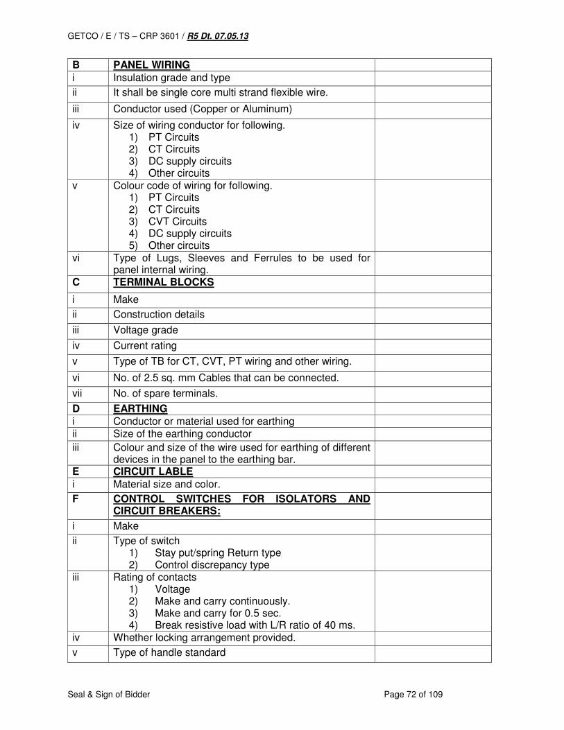
GETCO / E / TS – CRP 3601 / R5 Dt. 07.05.13
Seal & Sign of Bidder Page 72 of 109
B PANEL WIRING i Insulation grade and type
ii It shall be single core multi strand flexible wire.
iii Conductor used (Copper or Aluminum)
iv Size of wiring conductor for following. 1) PT Circuits 2) CT Circuits 3) DC supply circuits 4) Other circuits
v Colour code of wiring for following. 1) PT Circuits 2) CT Circuits 3) CVT Circuits 4) DC supply circuits 5) Other circuits
vi Type of Lugs, Sleeves and Ferrules to be used for panel internal wiring.
C TERMINAL BLOCKS
i Make
ii Construction details
iii Voltage grade
iv Current rating
v Type of TB for CT, CVT, PT wiring and other wiring.
vi No. of 2.5 sq. mm Cables that can be connected.
vii No. of spare terminals.
D EARTHING i Conductor or material used for earthing ii Size of the earthing conductor
iii Colour and size of the wire used for earthing of different devices in the panel to the earthing bar.
E CIRCUIT LABLE i Material size and color.
F CONTROL SWITCHES FOR ISOLATORS AND CIRCUIT BREAKERS:
i Make
ii Type of switch 1) Stay put/spring Return type 2) Control discrepancy type
iii Rating of contacts 1) Voltage 2) Make and carry continuously. 3) Make and carry for 0.5 sec. 4) Break resistive load with L/R ratio of 40 ms.
iv Whether locking arrangement provided.
v Type of handle standard

GETCO / E / TS – CRP 3601 / R5 Dt. 07.05.13
Seal & Sign of Bidder Page 73 of 109
vi Dimensions
vii Mounting details and drawing no.
viii Detailed technical literature furnished. ix Other information, if any.
G SEMAPHORE INDICATORS i Make
ii Type
iii Diameter of the disc.
iv Operating voltage v Burden vi Whether latch in Mechanism provided.
H PUSH BUTTONS
i Make
ii Type
iii Contact type(momentary/maintained)
iv Whether shrouding provided to prevent inadvertent operation.
v Whether integral engraved integral plates provided.
vi No. of NO/NC contacts.
I INDICATING LAMPS LED
i Make
ii Type
iii Size of lamps
iv Colour of lamps
v Life of LED in burning hours.
vi Dimensions and mounting details.
vii Other information, if any.
J ANNUNCIATORS
i Make
ii Type
iii Whether conforms to following. 1. It shall be Microprocessor based. 2. Window shall be replaceable. 3. NO/NC selectable 4. Sequence/ grouping selectable 5. Choice of colors 6. Choice of windows sizes 7. Availability of serial part (RS232 to RS 485)
output for computer connection 8. It shall have repeat relay card 9. AC/DC fail facility and LED facia 10. Windows based PC software 11. Cables, converters etc. shall also be provided
iv No. of points.
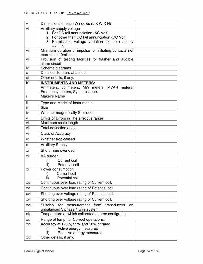
GETCO / E / TS – CRP 3601 / R5 Dt. 07.05.13
Seal & Sign of Bidder Page 74 of 109
v Dimensions of each Windows (L X W X H)
vi Auxiliary supply voltage 1. For DC fail annunciation (AC Volt) 2. For other than DC fail annunciation (DC Volt) 3. Permissible voltage variation for both supply
+ / - %
vii Minimum duration of impulse for initiating contacts not more than 10milisec.
viii Provision of testing facilities for flasher and audible alarm circuit
ix Scheme diagrams x Detailed literature attached.
xi Other details, if any.
K INSTRUMENTS AND METERS: Ammeters, voltmeters, MW meters, MVAR meters, Frequency meters, Synchroscope.
i Maker’s Name
ii Type and Model of Instruments
iii Size
iv Whether magnetically Shielded
v Limits of Errors in The effective range vi Maximum scale length
vii Total deflection angle
viii Class of Accuracy
ix Whether tropicalised
x Auxiliary Supply
xi Short Time overload
xii VA burden i) Current coil ii) Potential coil
xiii Power consumption i) Current coil
ii) Potential coil
xiv Continuous over load rating of Current coil.
xv Continuous over load rating of Potential coil.
xvi Shorting over voltage rating of Potential coil.
xvii Shorting over voltage rating of Current coil.
xviii Suitably for measurement from transducers on unbalanced 3 phase 4 wire system
xix Temperature at which calibrated degree centigrade.
xx Range of temp. for Correct operations.
xxi Accuracy at 125%, 25% and 10% of rated i) Active energy measured ii) Reactive energy measured
xxii Other details, if any.

GETCO / E / TS – CRP 3601 / R5 Dt. 07.05.13
Seal & Sign of Bidder Page 75 of 109
xxiii Type of mounting.
xxix Ref. no. of descriptive leaflet, submitted.
L SELECTOR SWITCHES:
i Make
ii Type
iii Type of handle
iv No, of position. v No. of contacts in each position
i) Open ii) Close
vi Making capacity of contacts vii Breaking capacity of contacts
viii Whether locking arrangement provided.
M TRANSDUCERS FOR MW/MVAR
i Make
ii Type iii Accuracy Class
iv P.T. ratio
v C.T ratio
vi Input a) Volts b) Amps.
vii Output DC mA
viii Measuring Range for MW
ix Measuring range for MVAR
x % AC Ripple on output
xi Load Resistance in Ohm
xii Aux Voltage
xiii Response Time
xiv Working Temp range
N TRANSDUCERS FOR VOLTMETRS
i Make
ii Type
iii Accuracy Class
iv PT/CVT ratio
v Input Amps
vi Output DC mA
vii Measuring range output.
viii % AC Ripple on output
ix Load Resistance in Ohm
x Aux Voltage required
xi Response Time
xii Working Temp range
O TRANSDUCERS FOR CURRENT MEASUREMENT
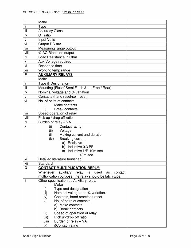
GETCO / E / TS – CRP 3601 / R5 Dt. 07.05.13
Seal & Sign of Bidder Page 76 of 109
i Make
ii Type
iii Accuracy Class
iv CT ratio
v Input Volts
vi Output DC mA
vii Measuring range output
viii % AC Ripple on output
ix Load Resistance in Ohm
x Aux Voltage required
xi Response time
xii Working temp range
P AUXILIARY RELAYS
i Make
ii Type & Designation
iii Mounting (Flush/ Semi Flush & on Front/ Rear)
iv Nominal voltage and % variation
v Contacts (hand reset/self reset)
vi No. of pairs of contacts i) Make contacts ii) Break contacts
vii Speed operation of relay
viii Pick up / drop off ratio
ix Burden of relay – VA
x (i) Contact rating (ii) Voltage (iii) Making current and duration (iv) Breaking current
a) Resistive b) Inductive 0.3 PF c) Inductive L/R 10m sec
40m sec
xi Detailed literature furnished.
xii Standard
Q CONTACT MULTIPLICATION REPLY:
i Whenever auxiliary relay is used as contact multiplication purpose, the relay should be latch type.
ii Other specification as Auxiliary relay. i) Make ii) Type and designation iii) Nominal voltage and % variation. iv) Contacts, hand reset/self reset. v) No. of pairs of contacts.
a) Make contacts b) Break contacts
vi) Speed of operation of relay vii) Pick up/drop off ratio viii) Burden of relay – VA ix) i)Contact rating
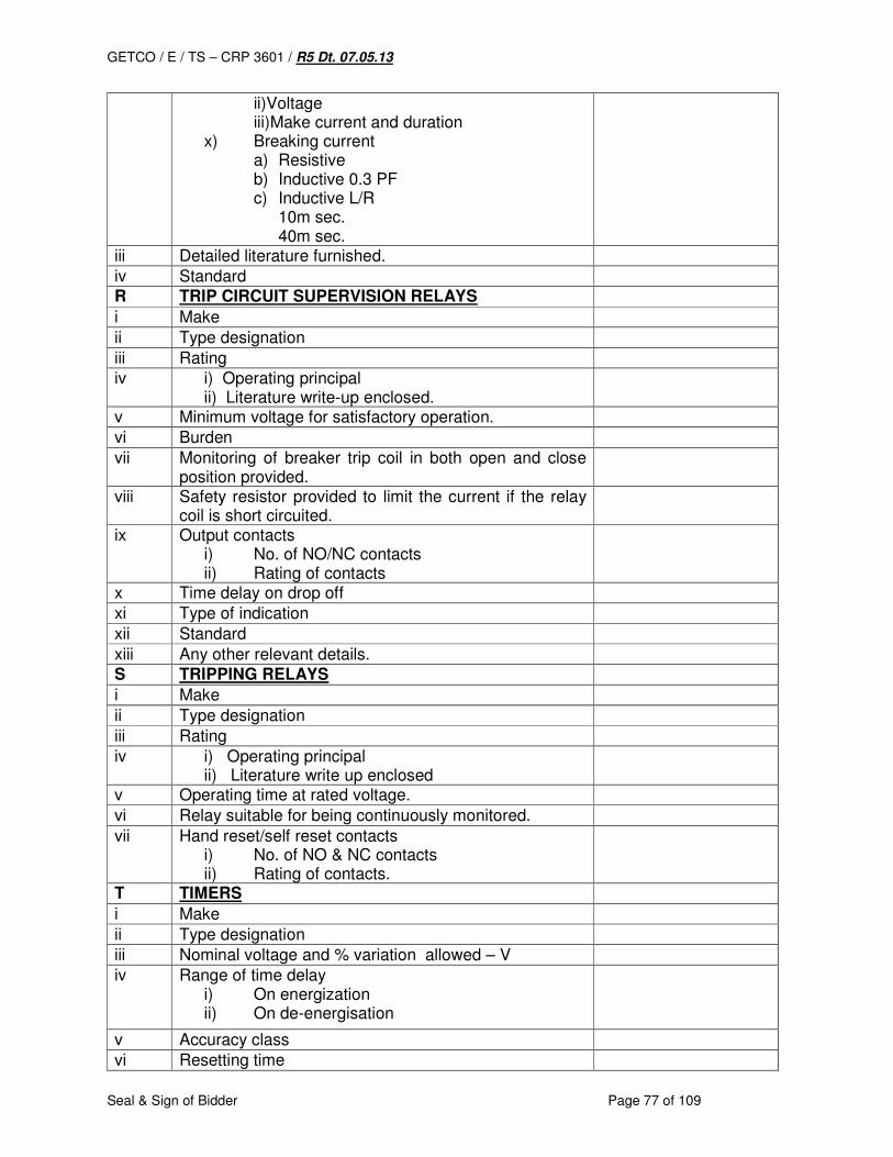
GETCO / E / TS – CRP 3601 / R5 Dt. 07.05.13
Seal & Sign of Bidder Page 77 of 109
ii)Voltage iii)Make current and duration
x) Breaking current a) Resistive b) Inductive 0.3 PF c) Inductive L/R
10m sec. 40m sec.
iii Detailed literature furnished.
iv Standard
R TRIP CIRCUIT SUPERVISION RELAYS
i Make
ii Type designation
iii Rating
iv i) Operating principal ii) Literature write-up enclosed.
v Minimum voltage for satisfactory operation.
vi Burden
vii Monitoring of breaker trip coil in both open and close position provided.
viii Safety resistor provided to limit the current if the relay coil is short circuited.
ix Output contacts i) No. of NO/NC contacts ii) Rating of contacts
x Time delay on drop off
xi Type of indication
xii Standard
xiii Any other relevant details.
S TRIPPING RELAYS
i Make
ii Type designation
iii Rating
iv i) Operating principal ii) Literature write up enclosed
v Operating time at rated voltage.
vi Relay suitable for being continuously monitored.
vii Hand reset/self reset contacts i) No. of NO & NC contacts ii) Rating of contacts.
T TIMERS
i Make
ii Type designation
iii Nominal voltage and % variation allowed – V
iv Range of time delay i) On energization ii) On de-energisation
v Accuracy class
vi Resetting time
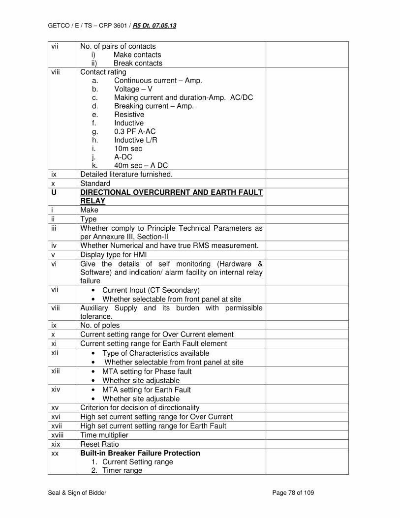
GETCO / E / TS – CRP 3601 / R5 Dt. 07.05.13
Seal & Sign of Bidder Page 78 of 109
vii No. of pairs of contacts i) Make contacts ii) Break contacts
viii Contact rating a. Continuous current – Amp. b. Voltage – V c. Making current and duration-Amp. AC/DC d. Breaking current – Amp. e. Resistive f. Inductive g. 0.3 PF A-AC h. Inductive L/R i. 10m sec j. A-DC k. 40m sec – A DC
ix Detailed literature furnished.
x Standard
U DIRECTIONAL OVERCURRENT AND EARTH FAULT RELAY
i Make
ii Type
iii Whether comply to Principle Technical Parameters as per Annexure III, Section-II
iv Whether Numerical and have true RMS measurement.
v Display type for HMI
vi Give the details of self monitoring (Hardware & Software) and indication/ alarm facility on internal relay failure
vii • Current Input (CT Secondary)
• Whether selectable from front panel at site
viii Auxiliary Supply and its burden with permissible tolerance.
ix No. of poles
x Current setting range for Over Current element
xi Current setting range for Earth Fault element
xii • Type of Characteristics available
• Whether selectable from front panel at site
xiii • MTA setting for Phase fault
• Whether site adjustable
xiv • MTA setting for Earth Fault
• Whether site adjustable
xv Criterion for decision of directionality
xvi High set current setting range for Over Current
xvii High set current setting range for Earth Fault
xviii Time multiplier
xix Reset Ratio
xx Built-in Breaker Failure Protection 1. Current Setting range 2. Timer range
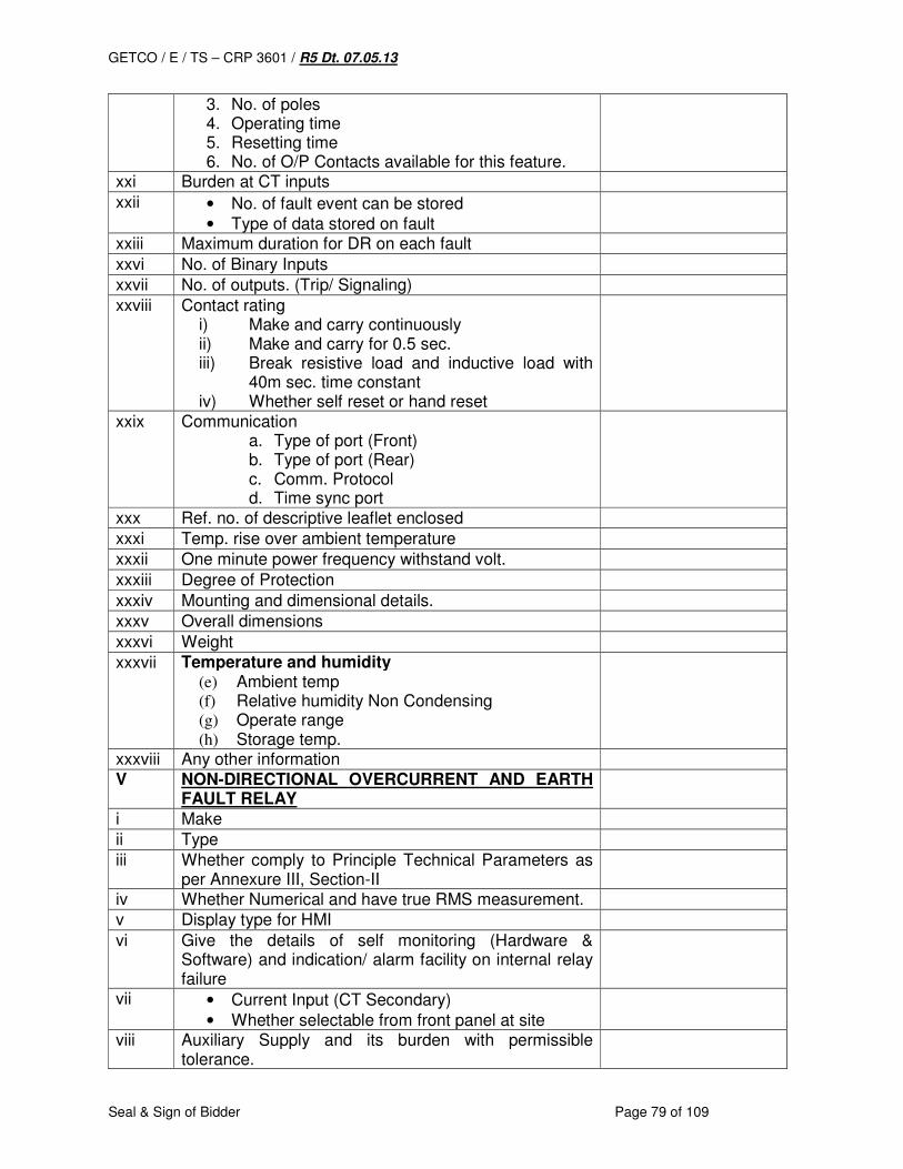
GETCO / E / TS – CRP 3601 / R5 Dt. 07.05.13
Seal & Sign of Bidder Page 79 of 109
3. No. of poles 4. Operating time 5. Resetting time 6. No. of O/P Contacts available for this feature.
xxi Burden at CT inputs
xxii • No. of fault event can be stored
• Type of data stored on fault
xxiii Maximum duration for DR on each fault
xxvi No. of Binary Inputs
xxvii No. of outputs. (Trip/ Signaling)
xxviii Contact rating i) Make and carry continuously ii) Make and carry for 0.5 sec. iii) Break resistive load and inductive load with
40m sec. time constant iv) Whether self reset or hand reset
xxix Communication a. Type of port (Front) b. Type of port (Rear) c. Comm. Protocol d. Time sync port
xxx Ref. no. of descriptive leaflet enclosed
xxxi Temp. rise over ambient temperature
xxxii One minute power frequency withstand volt.
xxxiii Degree of Protection
xxxiv Mounting and dimensional details.
xxxv Overall dimensions
xxxvi Weight
xxxvii Temperature and humidity (e) Ambient temp (f) Relative humidity Non Condensing (g) Operate range (h) Storage temp.
xxxviii Any other information
V NON-DIRECTIONAL OVERCURRENT AND EARTH FAULT RELAY
i Make
ii Type
iii Whether comply to Principle Technical Parameters as per Annexure III, Section-II
iv Whether Numerical and have true RMS measurement.
v Display type for HMI
vi Give the details of self monitoring (Hardware & Software) and indication/ alarm facility on internal relay failure
vii • Current Input (CT Secondary)
• Whether selectable from front panel at site
viii Auxiliary Supply and its burden with permissible tolerance.
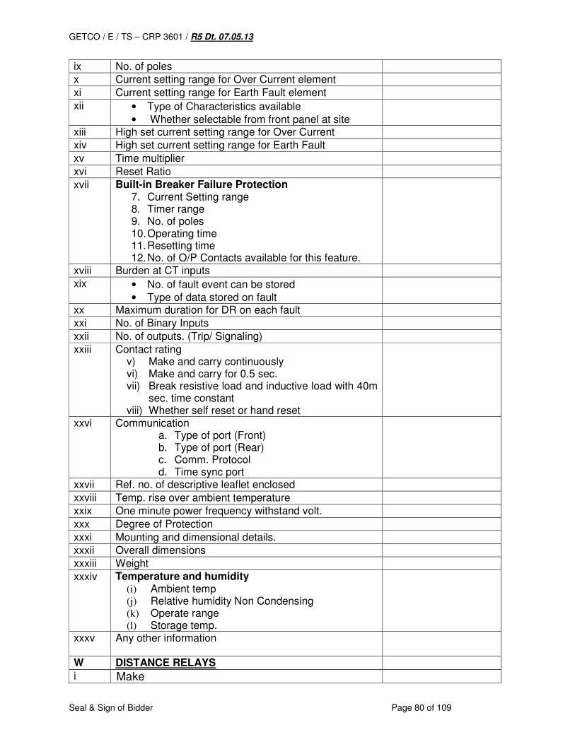
GETCO / E / TS – CRP 3601 / R5 Dt. 07.05.13
Seal & Sign of Bidder Page 80 of 109
ix No. of poles
x Current setting range for Over Current element
xi Current setting range for Earth Fault element
xii • Type of Characteristics available
• Whether selectable from front panel at site
xiii High set current setting range for Over Current
xiv High set current setting range for Earth Fault
xv Time multiplier
xvi Reset Ratio
xvii Built-in Breaker Failure Protection 7. Current Setting range 8. Timer range 9. No. of poles 10. Operating time 11. Resetting time 12. No. of O/P Contacts available for this feature.
xviii Burden at CT inputs
xix • No. of fault event can be stored
• Type of data stored on fault
xx Maximum duration for DR on each fault
xxi No. of Binary Inputs
xxii No. of outputs. (Trip/ Signaling)
xxiii Contact rating v) Make and carry continuously vi) Make and carry for 0.5 sec. vii) Break resistive load and inductive load with 40m
sec. time constant viii) Whether self reset or hand reset
xxvi Communication a. Type of port (Front) b. Type of port (Rear) c. Comm. Protocol d. Time sync port
xxvii Ref. no. of descriptive leaflet enclosed
xxviii Temp. rise over ambient temperature
xxix One minute power frequency withstand volt.
xxx Degree of Protection
xxxi Mounting and dimensional details.
xxxii Overall dimensions
xxxiii Weight
xxxiv Temperature and humidity (i) Ambient temp (j) Relative humidity Non Condensing (k) Operate range (l) Storage temp.
xxxv Any other information
W DISTANCE RELAYS
i Make
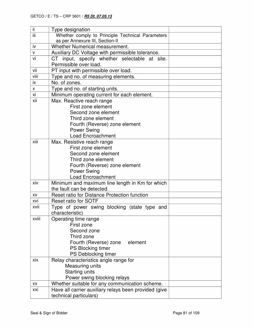
GETCO / E / TS – CRP 3601 / R5 Dt. 07.05.13
Seal & Sign of Bidder Page 81 of 109
ii Type designation
iii Whether comply to Principle Technical Parameters as per Annexure III, Section-II
iv Whether Numerical measurement.
v Auxiliary DC Voltage with permissible tolerance.
vi CT input, specify whether selectable at site. Permissible over load.
vii PT input with permissible over load.
viii Type and no. of measuring elements.
ix No. of zones.
x Type and no. of starting units.
xi Minimum operating current for each element.
xii Max. Reactive reach range First zone element Second zone element Third zone element Fourth (Reverse) zone element Power Swing Load Encroachment
xiii Max. Resistive reach range First zone element Second zone element
Third zone element Fourth (Reverse) zone element Power Swing
Load Encroachment
xiv Minimum and maximum line length in Km for which the fault can be detected.
xv Reset ratio for Distance Protection function
xvi Reset ratio for SOTF
xvii Type of power swing blocking (state type and characteristic)
xviii Operating time range First zone Second zone Third zone Fourth (Reverse) zone element PS Blocking timer PS Deblocking timer
xix Relay characteristics angle range for Measuring units Starting units
Power swing blocking relays
xx Whether suitable for any communication scheme.
xxi Have all carrier auxiliary relays been provided (give technical particulars)
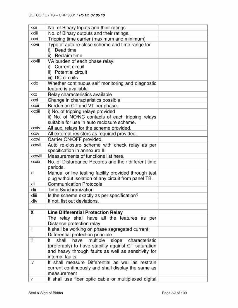
GETCO / E / TS – CRP 3601 / R5 Dt. 07.05.13
Seal & Sign of Bidder Page 82 of 109
xxii No. of Binary Inputs and their ratings.
xxiii No. of Binary outputs and their ratings.
xxvi Tripping time carrier (maximum and minimum)
xxvii Type of auto re-close scheme and time range for i) Dead time ii) Reclaim time
xxviii VA burden of each phase relay. i) Current circuit ii) Potential circuit iii) DC circuits
xxix Whether continuous self monitoring and diagnostic feature is available.
xxx Relay characteristics available
xxxi Change in characteristics possible
xxxii Burden on CT and VT per phase.
xxxiii i) No. of tripping relays provided ii) No. of NO/NC contacts of each tripping relays suitable for use in auto reclosure scheme.
xxxiv All aux. relays for the scheme provided.
xxxv All external resistors as required provided.
xxxvi Carrier ON/OFF provided.
xxxvii Auto re-closure scheme with check relay as per specification in annexure III
xxxviii Measurements of functions list here.
xxxix No. of Disturbance Records and their different time periods.
xl Manual online testing facility provided through test plug without isolation of any circuit from panel TB.
xli Communication Protocols
xlii Time Synchronization
xliii Is the scheme exactly as per specification?
xliv If not, list out deviations.
X Line Differential Protection Relay
i The relay shall have all the features as per Distance protection relay
ii It shall be working on phase segregated current Differential protection principle
iii It shall have multiple slope characteristic (preferably) to have stability against CT saturation and heavy through faults as well as sensitivity for internal faults
iv It shall measure Differential as well as restrain current continuously and shall display the same as measurement
v It shall use fiber optic cable or multiplexed digital
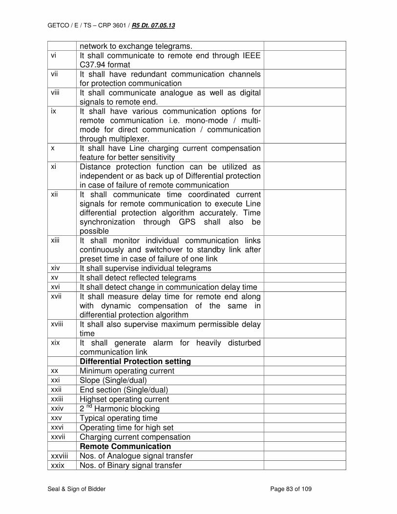
GETCO / E / TS – CRP 3601 / R5 Dt. 07.05.13
Seal & Sign of Bidder Page 83 of 109
network to exchange telegrams. vi It shall communicate to remote end through IEEE
C37.94 format
vii It shall have redundant communication channels for protection communication
viii It shall communicate analogue as well as digital signals to remote end.
ix It shall have various communication options for remote communication i.e. mono-mode / multi-mode for direct communication / communication through multiplexer.
x It shall have Line charging current compensation feature for better sensitivity
xi Distance protection function can be utilized as independent or as back up of Differential protection in case of failure of remote communication
xii It shall communicate time coordinated current signals for remote communication to execute Line differential protection algorithm accurately. Time synchronization through GPS shall also be possible
xiii It shall monitor individual communication links continuously and switchover to standby link after preset time in case of failure of one link
xiv It shall supervise individual telegrams
xv It shall detect reflected telegrams
xvi It shall detect change in communication delay time
xvii It shall measure delay time for remote end along with dynamic compensation of the same in differential protection algorithm
xviii It shall also supervise maximum permissible delay time
xix It shall generate alarm for heavily disturbed communication link
Differential Protection setting
xx Minimum operating current
xxi Slope (Single/dual)
xxii End section (Single/dual)
xxiii Highset operating current
xxiv 2 nd Harmonic blocking
xxv Typical operating time
xxvi Operating time for high set
xxvii Charging current compensation
Remote Communication
xxviii Nos. of Analogue signal transfer
xxix Nos. of Binary signal transfer
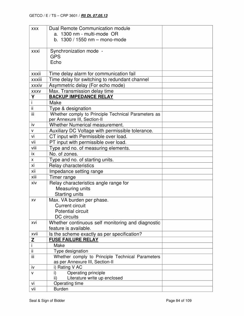
GETCO / E / TS – CRP 3601 / R5 Dt. 07.05.13
Seal & Sign of Bidder Page 84 of 109
xxx Dual Remote Communication module a. 1300 nm - multi-mode OR b. 1300 / 1550 nm – mono-mode
xxxi Synchronization mode - GPS Echo
xxxii Time delay alarm for communication fail
xxxiii Time delay for switching to redundant channel
xxxiv Asymmetric delay (For echo mode)
xxxv Max. Transmission delay time
Y BACKUP IMPEDANCE RELAY
i Make
ii Type & designation
iii Whether comply to Principle Technical Parameters as per Annexure III, Section-II
iv Whether Numerical measurement.
v Auxiliary DC Voltage with permissible tolerance.
vi CT input with Permissible over load.
vii PT input with permissible over load.
viii Type and no. of measuring elements.
ix No. of zones.
x Type and no. of starting units.
xi Relay characteristics
xii Impedance setting range
xiii Timer range
xiv Relay characteristics angle range for Measuring units Starting units
xv Max. VA burden per phase. Current circuit Potential circuit
DC circuits
xvi Whether continuous self monitoring and diagnostic feature is available.
xvii Is the scheme exactly as per specification?
Z FUSE FAILURE RELAY
i Make
ii Type designation
iii Whether comply to Principle Technical Parameters as per Annexure III, Section-II
iv i) Rating V AC
v i) Operating principle ii) Literature write up enclosed
vi Operating time
vii Burden
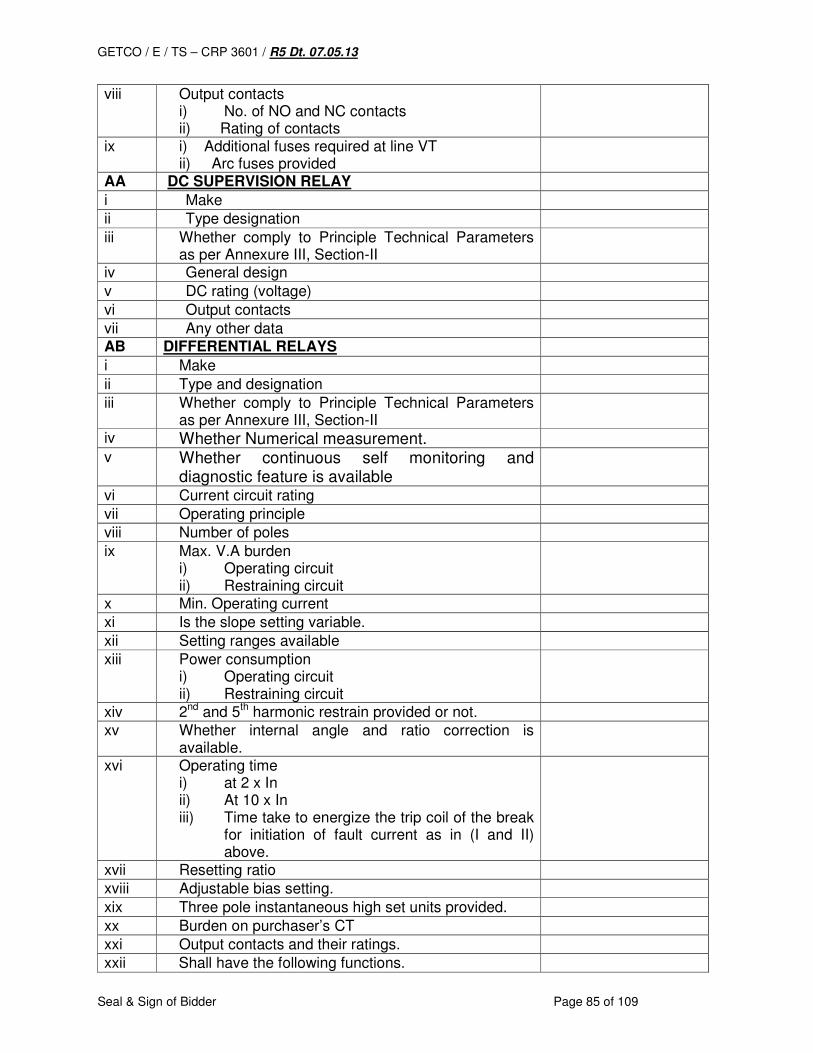
GETCO / E / TS – CRP 3601 / R5 Dt. 07.05.13
Seal & Sign of Bidder Page 85 of 109
viii Output contacts i) No. of NO and NC contacts ii) Rating of contacts
ix i) Additional fuses required at line VT ii) Arc fuses provided
AA DC SUPERVISION RELAY
i Make
ii Type designation
iii Whether comply to Principle Technical Parameters as per Annexure III, Section-II
iv General design
v DC rating (voltage)
vi Output contacts
vii Any other data AB DIFFERENTIAL RELAYS
i Make
ii Type and designation
iii Whether comply to Principle Technical Parameters as per Annexure III, Section-II
iv Whether Numerical measurement.
v Whether continuous self monitoring and diagnostic feature is available
vi Current circuit rating
vii Operating principle
viii Number of poles
ix Max. V.A burden i) Operating circuit ii) Restraining circuit
x Min. Operating current
xi Is the slope setting variable.
xii Setting ranges available
xiii Power consumption i) Operating circuit ii) Restraining circuit
xiv 2nd and 5th harmonic restrain provided or not.
xv Whether internal angle and ratio correction is available.
xvi Operating time i) at 2 x In ii) At 10 x In iii) Time take to energize the trip coil of the break
for initiation of fault current as in (I and II) above.
xvii Resetting ratio
xviii Adjustable bias setting.
xix Three pole instantaneous high set units provided.
xx Burden on purchaser’s CT
xxi Output contacts and their ratings.
xxii Shall have the following functions.
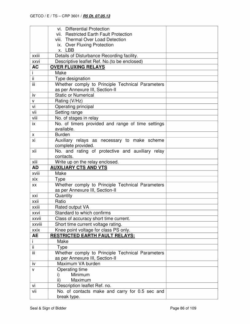
GETCO / E / TS – CRP 3601 / R5 Dt. 07.05.13
Seal & Sign of Bidder Page 86 of 109
vi. Differential Protection vii. Restricted Earth Fault Protection viii. Thermal Over Load Detection ix. Over Fluxing Protection x. LBB
xxiii Details of Disturbance Recording facility.
xxvi Descriptive leaflet Ref. No.(to be enclosed) AC OVER FLUXING RELAYS
i Make
ii Type designation
iii Whether comply to Principle Technical Parameters as per Annexure III, Section-II
iv Static or Numerical
v Rating (V/Hz)
vi Operating principal
vii Setting range
viii No. of stages in relay
ix No. of timers provided and range of time settings available.
x Burden
xi Auxiliary relays as necessary to make scheme complete provided.
xii No. and rating of protective and auxiliary relay contacts.
xiii Write up on the relay enclosed.
AD AUXILIARY CTS AND VTS
xviii Make
xix Type
xx Whether comply to Principle Technical Parameters as per Annexure III, Section-II
xxi Quantity
xxii Ratio
xxiii Rated output VA
xxvi Standard to which confirms
xxvii Class of accuracy short time current.
xxviii Short time current voltage rating.
xxix Knee point voltage for class PS only.
AE RESTRICTED EARTH FAULT RELAYS:
i Make
ii Type
iii Whether comply to Principle Technical Parameters as per Annexure III, Section-II
iv Maximum VA burden
v Operating time i) Minimum ii) Maximum
vi Description leaflet Ref. no.
vii No. of contacts make and carry for 0.5 sec and break type.

GETCO / E / TS – CRP 3601 / R5 Dt. 07.05.13
Seal & Sign of Bidder Page 87 of 109
viii Whether contacts self reset or hand reset.
ix Contact ratings i) Make and carry continuously ii) Make and carry for 0.5 sec. iii) Break resistive load and inductive load with 40
m. sec. time current.
x Setting range.
AF BUS DIFFERENTIAL RELAY
i Make
ii Type designation
iii Whether comply to Principle Technical Parameters as per Annexure III, Section-II
iv Bus Bar Protection Functions: 1. Min fault current pick-up range (Ikmin) 2. Neutral current Detection range 3. Stabilizing factor (K) 4. Diff current Alarm setting range 5. Time Delay for (4) above 6. Isolator alarm time delay setting 7. Typical tripping time
v Check Zone: 1. Min fault current pick-up range (Ikmin) 2. Stabilizing factor (K)
vi Analog Inputs (Bay or Peripheral or Field Unit): 1. Maximum no. of Bays which can be connected
with central unit 2. Current Rating 3. Thermal Ratings: Continuous For 10 s, Minimum 10xIn For 1 s, 100xIn 4. Voltage Rating 5. Auxiliary Supply
vii Binary Inputs/ Outputs: 1. Operating Time 2. Max Operating Volt 3. Max Cont rating 4. Max make & Carry 5. Max making power 6. Whether Binary O/P Reset Programmable 7. Breaking Current: Heavy Duty N/O Contact: Signaling Contact: 8. No. of I/P per bay unit: 9. No. of I/P for central unit: 10. Pickup current for I/P: 11. Operating Time for I/P:

GETCO / E / TS – CRP 3601 / R5 Dt. 07.05.13
Seal & Sign of Bidder Page 88 of 109
viii Auxiliary Supply: 1. Input Voltage: 2. Load: (Bay Unit)
(Central Unit) 3. Front plate Signal 4. Switch 5. Redundant power Supply: Optional
ix Optical Interface: 1. Number of Cores 2. Core/ sheath diameter 3. Max permissible attenuation 4. Connector:
x Event Recorder: It shall have event recording facility for minimum last 50 Operational/ fault events.
xi Disturbance Recorder: 1. Independent setting for pre-fault and post-fault
period 2. Format
xii Local & Remote communication: 1. Serial interface for connecting a PC, either
directly or via a modem. 2. System interface for connecting to a control
system via IEC 61850. 3. System interfaces via IEC 61850 protocol for
interbay bus supports. 4. Time synchronization via IRIG-B.
xiii Maximum fault current for which 100% stability can be achieved.
xiv Impedance type and operating characteristic
xv Continuous supervision of CT secondary against open circuit
xvi Architecture & Interconnection of Central unit and bay unit panel.
xvii Principle of CT ratio error matching
xviii Measuring and tripping criterion
xix HMI details
xx Self supervision and diagnostic facility.
xxi Measurements available
xxii Whether bus bar image for each bay is formed and displayed in HMI
xxiii Redundant hardware available
xxvi Standard functions available
xxvii Optional functions available
xxviii Reset through a single push button
xxix Future configuration and activation of new bays should be possible
xxx Any deviations
xxxi Any other details
AG GENERAL
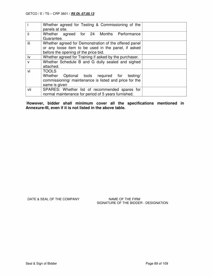
GETCO / E / TS – CRP 3601 / R5 Dt. 07.05.13
Seal & Sign of Bidder Page 89 of 109
i Whether agreed for Testing & Commissioning of the panels at site.
ii Whether agreed for 24 Months Performance Guarantee.
iii Whether agreed for Demonstration of the offered panel or any loose item to be used in the panel, if asked before the opening of the price bid.
iv Whether agreed for Training if asked by the purchaser.
v Whether Schedule B and G dully sealed and sighed attached.
vi TOOLS Whether Optional tools required for testing/ commissioning/ maintenance is listed and price for the same is given
vii SPARES: Whether list of recommended spares for normal maintenance for period of 5 years furnished.
However, bidder shall minimum cover all the specifications mentioned in Annexure-III, even if it is not listed in the above table. DATE & SEAL OF THE COMPANY NAME OF THE FIRM
SIGNATURE OF THE BIDDER - DESIGNATION

GETCO / E / TS – CRP 3601 / R5 Dt. 07.05.13
Seal & Sign of Bidder Page 90 of 109
SCHEDULE: G LIST OF EQUIPMENT FOR CONTROL AND RELAY PANELS
(TO BE FILLED IN BY THE BIDDER)
Sr.no. Description Qty. reqd. Make and type designation
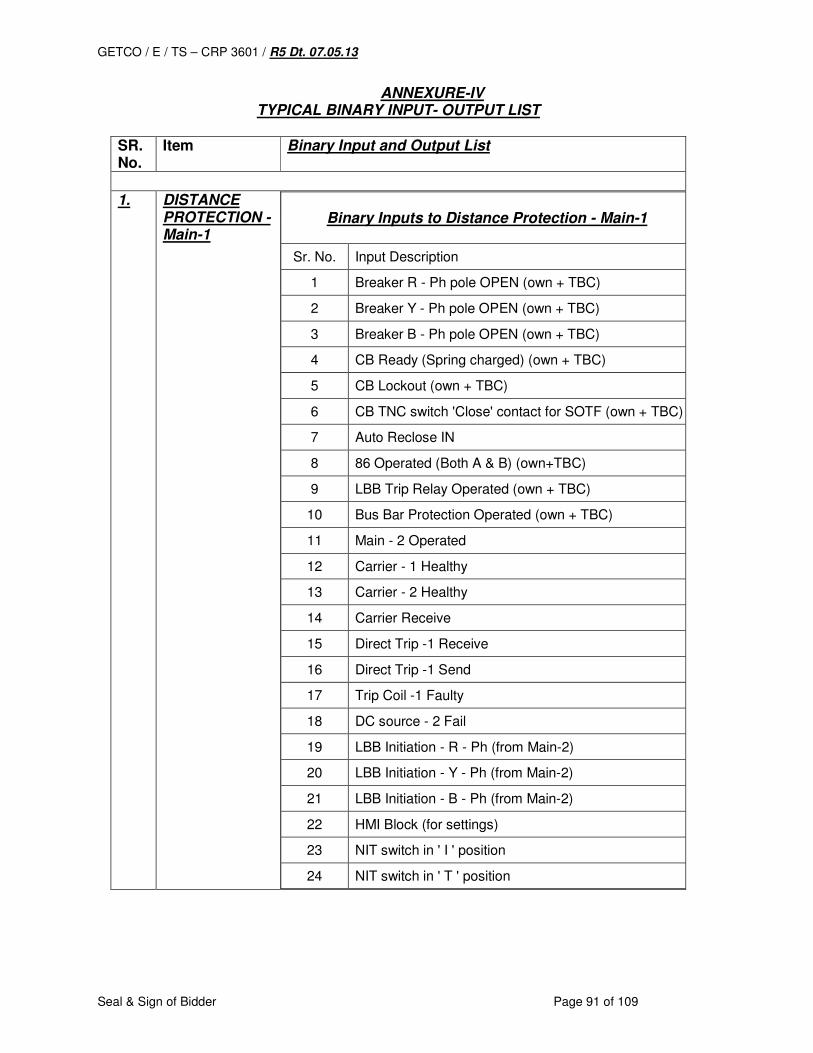
GETCO / E / TS – CRP 3601 / R5 Dt. 07.05.13
Seal & Sign of Bidder Page 91 of 109
ANNEXURE-IV TYPICAL BINARY INPUT- OUTPUT LIST
SR. No.
Item Binary Input and Output List
1. DISTANCE
PROTECTION - Main-1
Binary Inputs to Distance Protection - Main-1
Sr. No. Input Description
1 Breaker R - Ph pole OPEN (own + TBC)
2 Breaker Y - Ph pole OPEN (own + TBC)
3 Breaker B - Ph pole OPEN (own + TBC)
4 CB Ready (Spring charged) (own + TBC)
5 CB Lockout (own + TBC)
6 CB TNC switch 'Close' contact for SOTF (own + TBC)
7 Auto Reclose IN
8 86 Operated (Both A & B) (own+TBC)
9 LBB Trip Relay Operated (own + TBC)
10 Bus Bar Protection Operated (own + TBC)
11 Main - 2 Operated
12 Carrier - 1 Healthy
13 Carrier - 2 Healthy
14 Carrier Receive
15 Direct Trip -1 Receive
16 Direct Trip -1 Send
17 Trip Coil -1 Faulty
18 DC source - 2 Fail
19 LBB Initiation - R - Ph (from Main-2)
20 LBB Initiation - Y - Ph (from Main-2)
21 LBB Initiation - B - Ph (from Main-2)
22 HMI Block (for settings)
23 NIT switch in ' I ' position
24 NIT switch in ' T ' position
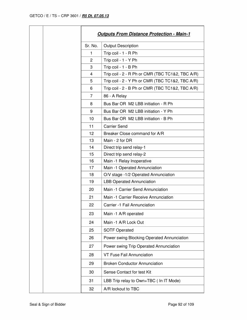
GETCO / E / TS – CRP 3601 / R5 Dt. 07.05.13
Seal & Sign of Bidder Page 92 of 109
Outputs From Distance Protection - Main-1
Sr. No. Output Description
1 Trip coil - 1 - R Ph
2 Trip coil - 1 - Y Ph
3 Trip coil - 1 - B Ph
4 Trip coil - 2 - R Ph or CMR (TBC TC1&2, TBC A/R)
5 Trip coil - 2 - Y Ph or CMR (TBC TC1&2, TBC A/R)
6 Trip coil - 2 - B Ph or CMR (TBC TC1&2, TBC A/R)
7 86 - A Relay
8 Bus Bar OR M2 LBB initiation - R Ph
9 Bus Bar OR M2 LBB initiation - Y Ph
10 Bus Bar OR M2 LBB initiation - B Ph
11 Carrier Send
12 Breaker Close command for A/R
13 Main - 2 for DR
14 Direct trip send relay-1
15 Direct trip send relay-2
16 Main -1 Relay Inoperative
17 Main -1 Operated Annunciation
18 O/V stage -1/2 Operated Annunciation
19 LBB Operated Annunciation
20 Main -1 Carrier Send Annunciation
21 Main -1 Carrier Receive Annunciation
22 Carrier -1 Fail Annunciation
23 Main -1 A/R operated
24 Main -1 A/R Lock Out
25 SOTF Operated
26 Power swing Blocking Operated Annunciation
27 Power swing Trip Operated Annunciation
28 VT Fuse Fail Annunciation
29 Broken Conductor Annunciation
30 Sense Contact for test Kit
31 LBB Trip relay to Own+TBC ( In IT Mode)
32 A/R lockout to TBC
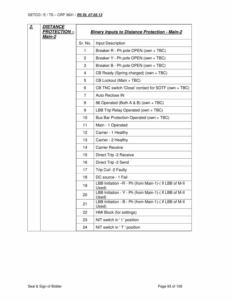
GETCO / E / TS – CRP 3601 / R5 Dt. 07.05.13
Seal & Sign of Bidder Page 93 of 109
2. DISTANCE PROTECTION – Main-2
Binary Inputs to Distance Protection - Main-2
Sr. No. Input Description
1 Breaker R - Ph pole OPEN (own + TBC)
2 Breaker Y - Ph pole OPEN (own + TBC)
3 Breaker B - Ph pole OPEN (own + TBC)
4 CB Ready (Spring charged) (own + TBC)
5 CB Lockout (Main + TBC)
6 CB TNC switch 'Close' contact for SOTF (own + TBC)
7 Auto Reclose IN
8 86 Operated (Both A & B) (own + TBC)
9 LBB Trip Relay Operated (own + TBC)
10 Bus Bar Protection Operated (own + TBC)
11 Main - 1 Operated
12 Carrier - 1 Healthy
13 Carrier - 2 Healthy
14 Carrier Receive
15 Direct Trip -2 Receive
16 Direct Trip -2 Send
17 Trip Coil -2 Faulty
18 DC source - 1 Fail
19 LBB Initiation –R - Ph (from Main-1)-( If LBB of M-II Used)
20 LBB Initiation - Y - Ph (from Main-1)-( If LBB of M-II Used)
21 LBB Initiation - B - Ph (from Main-1)-( If LBB of M-II Used)
22 HMI Block (for settings)
23 NIT switch in ' I ' position
24 NIT switch in ' T ' position
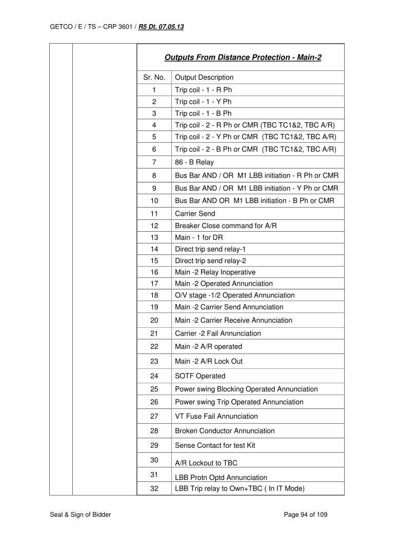
GETCO / E / TS – CRP 3601 / R5 Dt. 07.05.13
Seal & Sign of Bidder Page 94 of 109
Outputs From Distance Protection - Main-2
Sr. No. Output Description
1 Trip coil - 1 - R Ph
2 Trip coil - 1 - Y Ph
3 Trip coil - 1 - B Ph
4 Trip coil - 2 - R Ph or CMR (TBC TC1&2, TBC A/R)
5 Trip coil - 2 - Y Ph or CMR (TBC TC1&2, TBC A/R)
6 Trip coil - 2 - B Ph or CMR (TBC TC1&2, TBC A/R)
7 86 - B Relay
8 Bus Bar AND / OR M1 LBB initiation - R Ph or CMR
9 Bus Bar AND / OR M1 LBB initiation - Y Ph or CMR
10 Bus Bar AND OR M1 LBB initiation - B Ph or CMR
11 Carrier Send
12 Breaker Close command for A/R
13 Main - 1 for DR
14 Direct trip send relay-1
15 Direct trip send relay-2
16 Main -2 Relay Inoperative
17 Main -2 Operated Annunciation
18 O/V stage -1/2 Operated Annunciation
19 Main -2 Carrier Send Annunciation
20 Main -2 Carrier Receive Annunciation
21 Carrier -2 Fail Annunciation
22 Main -2 A/R operated
23 Main -2 A/R Lock Out
24 SOTF Operated
25 Power swing Blocking Operated Annunciation
26 Power swing Trip Operated Annunciation
27 VT Fuse Fail Annunciation
28 Broken Conductor Annunciation
29 Sense Contact for test Kit
30 A/R Lockout to TBC
31 LBB Protn Optd Annunciation
32 LBB Trip relay to Own+TBC ( In IT Mode)
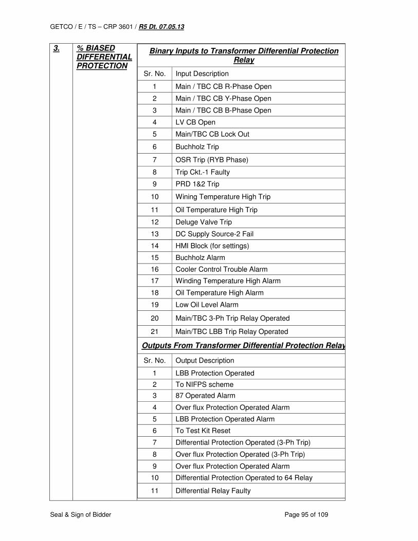
GETCO / E / TS – CRP 3601 / R5 Dt. 07.05.13
Seal & Sign of Bidder Page 95 of 109
3. % BIASED DIFFERENTIAL PROTECTION
Binary Inputs to Transformer Differential Protection Relay
Sr. No. Input Description
1 Main / TBC CB R-Phase Open
2 Main / TBC CB Y-Phase Open
3 Main / TBC CB B-Phase Open
4 LV CB Open
5 Main/TBC CB Lock Out
6 Buchholz Trip
7 OSR Trip (RYB Phase)
8 Trip Ckt.-1 Faulty
9 PRD 1&2 Trip
10 Wining Temperature High Trip
11 Oil Temperature High Trip
12 Deluge Valve Trip
13 DC Supply Source-2 Fail
14 HMI Block (for settings)
15 Buchholz Alarm
16 Cooler Control Trouble Alarm
17 Winding Temperature High Alarm
18 Oil Temperature High Alarm
19 Low Oil Level Alarm
20 Main/TBC 3-Ph Trip Relay Operated
21 Main/TBC LBB Trip Relay Operated
Outputs From Transformer Differential Protection Relay
Sr. No. Output Description
1 LBB Protection Operated
2 To NIFPS scheme
3 87 Operated Alarm
4 Over flux Protection Operated Alarm
5 LBB Protection Operated Alarm
6 To Test Kit Reset
7 Differential Protection Operated (3-Ph Trip)
8 Over flux Protection Operated (3-Ph Trip)
9 Over flux Protection Operated Alarm
10 Differential Protection Operated to 64 Relay
11 Differential Relay Faulty
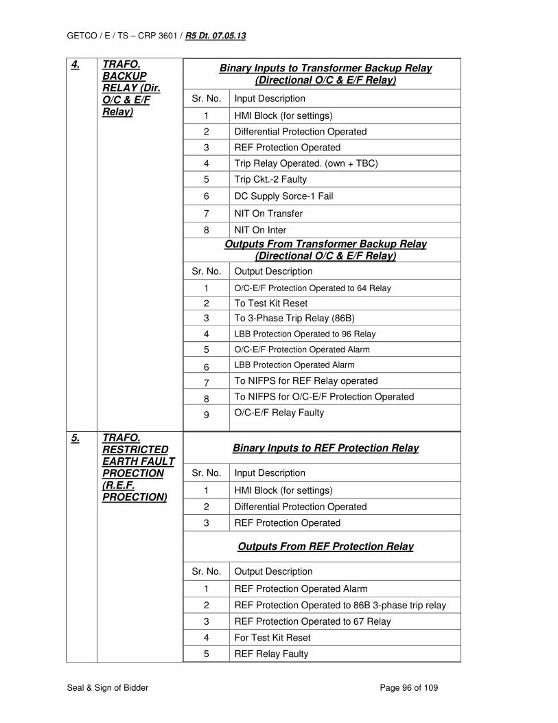
GETCO / E / TS – CRP 3601 / R5 Dt. 07.05.13
Seal & Sign of Bidder Page 96 of 109
4. TRAFO. BACKUP RELAY (Dir. O/C & E/F Relay)
Binary Inputs to Transformer Backup Relay (Directional O/C & E/F Relay)
Sr. No. Input Description
1 HMI Block (for settings)
2 Differential Protection Operated
3 REF Protection Operated
4 Trip Relay Operated. (own + TBC)
5 Trip Ckt.-2 Faulty
6 DC Supply Sorce-1 Fail
7 NIT On Transfer
8 NIT On Inter
Outputs From Transformer Backup Relay (Directional O/C & E/F Relay)
Sr. No. Output Description
1 O/C-E/F Protection Operated to 64 Relay
2 To Test Kit Reset
3 To 3-Phase Trip Relay (86B)
4 LBB Protection Operated to 96 Relay
5 O/C-E/F Protection Operated Alarm
6 LBB Protection Operated Alarm
7 To NIFPS for REF Relay operated
8 To NIFPS for O/C-E/F Protection Operated
9 O/C-E/F Relay Faulty
5. TRAFO. RESTRICTED EARTH FAULT PROECTION (R.E.F. PROECTION)
Binary Inputs to REF Protection Relay
Sr. No. Input Description
1 HMI Block (for settings)
2 Differential Protection Operated
3 REF Protection Operated
Outputs From REF Protection Relay
Sr. No. Output Description
1 REF Protection Operated Alarm
2 REF Protection Operated to 86B 3-phase trip relay
3 REF Protection Operated to 67 Relay
4 For Test Kit Reset
5 REF Relay Faulty
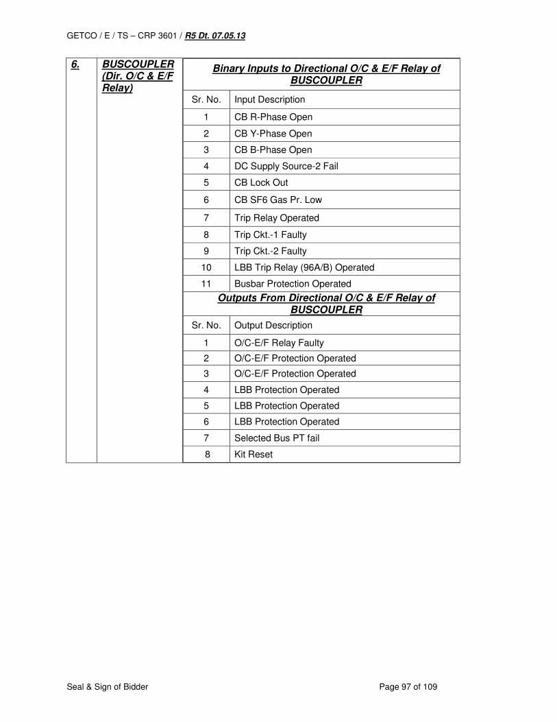
GETCO / E / TS – CRP 3601 / R5 Dt. 07.05.13
Seal & Sign of Bidder Page 97 of 109
6. BUSCOUPLER (Dir. O/C & E/F Relay)
Binary Inputs to Directional O/C & E/F Relay of BUSCOUPLER
Sr. No. Input Description
1 CB R-Phase Open
2 CB Y-Phase Open
3 CB B-Phase Open
4 DC Supply Source-2 Fail
5 CB Lock Out
6 CB SF6 Gas Pr. Low
7 Trip Relay Operated
8 Trip Ckt.-1 Faulty
9 Trip Ckt.-2 Faulty
10 LBB Trip Relay (96A/B) Operated
11 Busbar Protection Operated
Outputs From Directional O/C & E/F Relay of BUSCOUPLER
Sr. No. Output Description
1 O/C-E/F Relay Faulty
2 O/C-E/F Protection Operated
3 O/C-E/F Protection Operated
4 LBB Protection Operated
5 LBB Protection Operated
6 LBB Protection Operated
7 Selected Bus PT fail
8 Kit Reset
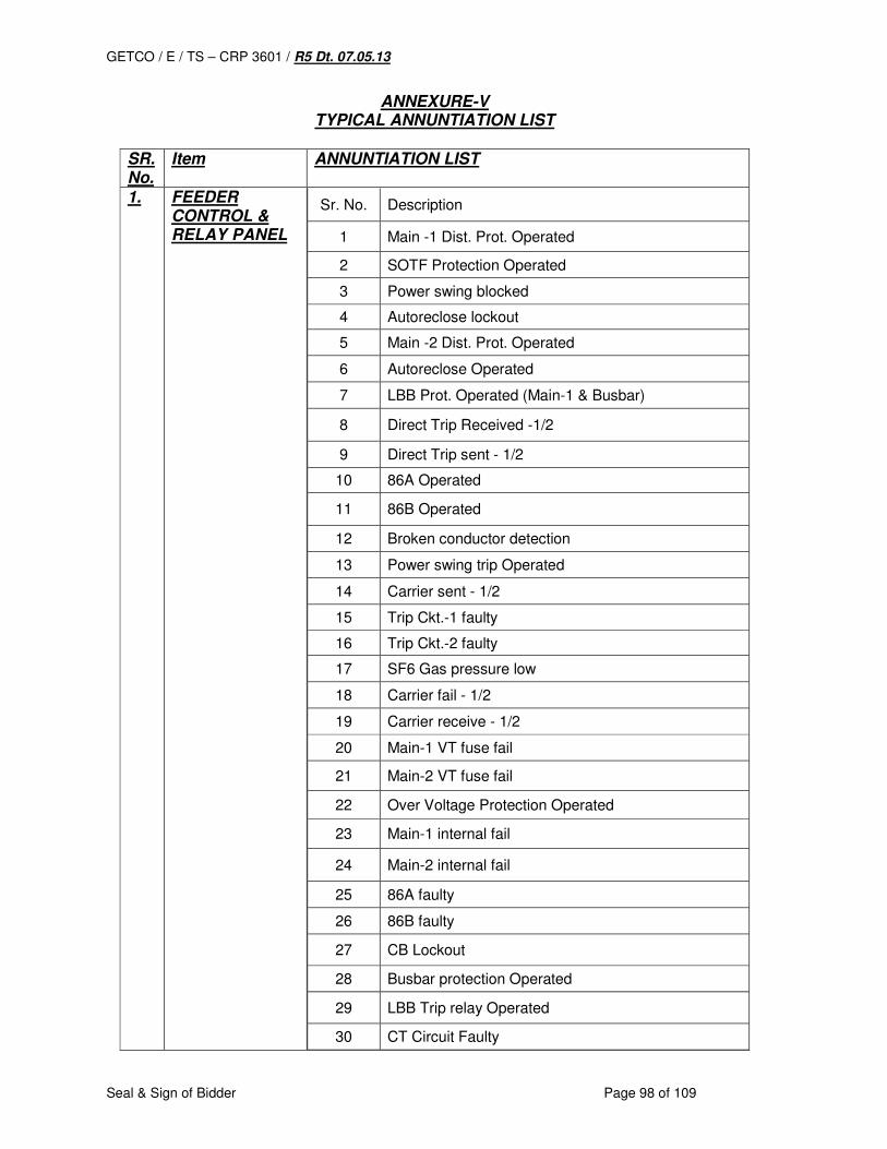
GETCO / E / TS – CRP 3601 / R5 Dt. 07.05.13
Seal & Sign of Bidder Page 98 of 109
ANNEXURE-V TYPICAL ANNUNTIATION LIST
SR. No.
Item ANNUNTIATION LIST
1. FEEDER CONTROL & RELAY PANEL
Sr. No. Description
1 Main -1 Dist. Prot. Operated
2 SOTF Protection Operated
3 Power swing blocked
4 Autoreclose lockout
5 Main -2 Dist. Prot. Operated
6 Autoreclose Operated
7 LBB Prot. Operated (Main-1 & Busbar)
8 Direct Trip Received -1/2
9 Direct Trip sent - 1/2
10 86A Operated
11 86B Operated
12 Broken conductor detection
13 Power swing trip Operated
14 Carrier sent - 1/2
15 Trip Ckt.-1 faulty
16 Trip Ckt.-2 faulty
17 SF6 Gas pressure low
18 Carrier fail - 1/2
19 Carrier receive - 1/2
20 Main-1 VT fuse fail
21 Main-2 VT fuse fail
22 Over Voltage Protection Operated
23 Main-1 internal fail
24 Main-2 internal fail
25 86A faulty
26 86B faulty
27 CB Lockout
28 Busbar protection Operated
29 LBB Trip relay Operated
30 CT Circuit Faulty
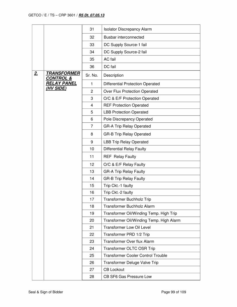
GETCO / E / TS – CRP 3601 / R5 Dt. 07.05.13
Seal & Sign of Bidder Page 99 of 109
31 Isolator Discrepancy Alarm
32 Busbar interconnected
33 DC Supply Source-1 fail
34 DC Supply Source-2 fail
35 AC fail
36 DC fail
2. TRANSFORMER CONTROL & RELAY PANEL (HV SIDE)
Sr. No. Description
1 Differential Protection Operated
2 Over Flux Protection Operated
3 O/C & E/F Protection Operated
4 REF Protection Operated
5 LBB Protection Operated
6 Pole Discrepancy Operated
7 GR-A Trip Relay Operated
8 GR-B Trip Relay Operated
9 LBB Trip Relay Operated
10 Differential Relay Faulty
11 REF Relay Faulty
12 O/C & E/F Relay Faulty
13 GR-A Trip Relay Faulty
14 GR-B Trip Relay Faulty
15 Trip Ckt.-1 faulty
16 Trip Ckt.-2 faulty
17 Transformer Buchholz Trip
18 Transformer Buchholz Alarm
19 Transformer Oil/Winding Temp. High Trip
20 Transformer Oil/Winding Temp. High Alarm
21 Transformer Low Oil Level
22 Transformer PRD 1/2 Trip
23 Transformer Over flux Alarm
24 Transformer OLTC OSR Trip
25 Transformer Cooler Control Trouble
26 Transformer Deluge Valve Trip
27 CB Lockout
28 CB SF6 Gas Pressure Low
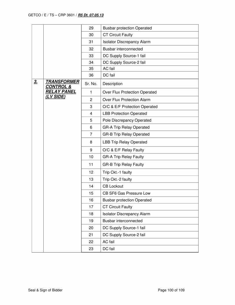
GETCO / E / TS – CRP 3601 / R5 Dt. 07.05.13
Seal & Sign of Bidder Page 100 of 109
29 Busbar protection Operated
30 CT Circuit Faulty
31 Isolator Discrepancy Alarm
32 Busbar interconnected
33 DC Supply Source-1 fail
34 DC Supply Source-2 fail
35 AC fail
36 DC fail
3. TRANSFORMER CONTROL & RELAY PANEL (LV SIDE)
Sr. No. Description
1 Over Flux Protection Operated
2 Over Flux Protection Alarm
3 O/C & E/F Protection Operated
4 LBB Protection Operated
5 Pole Discrepancy Operated
6 GR-A Trip Relay Operated
7 GR-B Trip Relay Operated
8 LBB Trip Relay Operated
9 O/C & E/F Relay Faulty
10 GR-A Trip Relay Faulty
11 GR-B Trip Relay Faulty
12 Trip Ckt.-1 faulty
13 Trip Ckt.-2 faulty
14 CB Lockout
15 CB SF6 Gas Pressure Low
16 Busbar protection Operated
17 CT Circuit Faulty
18 Isolator Discrepancy Alarm
19 Busbar interconnected
20 DC Supply Source-1 fail
21 DC Supply Source-2 fail
22 AC fail
23 DC fail
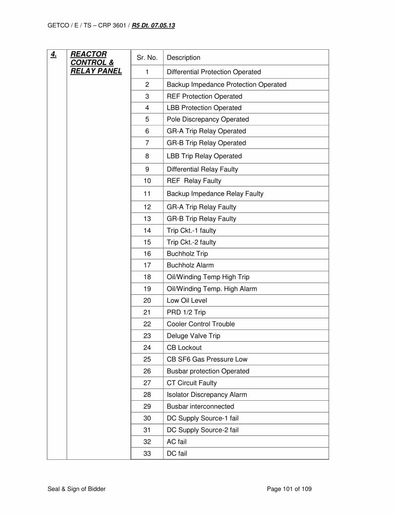
GETCO / E / TS – CRP 3601 / R5 Dt. 07.05.13
Seal & Sign of Bidder Page 101 of 109
4. REACTOR
CONTROL & RELAY PANEL
Sr. No. Description
1 Differential Protection Operated
2 Backup Impedance Protection Operated
3 REF Protection Operated
4 LBB Protection Operated
5 Pole Discrepancy Operated
6 GR-A Trip Relay Operated
7 GR-B Trip Relay Operated
8 LBB Trip Relay Operated
9 Differential Relay Faulty
10 REF Relay Faulty
11 Backup Impedance Relay Faulty
12 GR-A Trip Relay Faulty
13 GR-B Trip Relay Faulty
14 Trip Ckt.-1 faulty
15 Trip Ckt.-2 faulty
16 Buchholz Trip
17 Buchholz Alarm
18 Oil/Winding Temp High Trip
19 Oil/Winding Temp. High Alarm
20 Low Oil Level
21 PRD 1/2 Trip
22 Cooler Control Trouble
23 Deluge Valve Trip
24 CB Lockout
25 CB SF6 Gas Pressure Low
26 Busbar protection Operated
27 CT Circuit Faulty
28 Isolator Discrepancy Alarm
29 Busbar interconnected
30 DC Supply Source-1 fail
31 DC Supply Source-2 fail
32 AC fail
33 DC fail
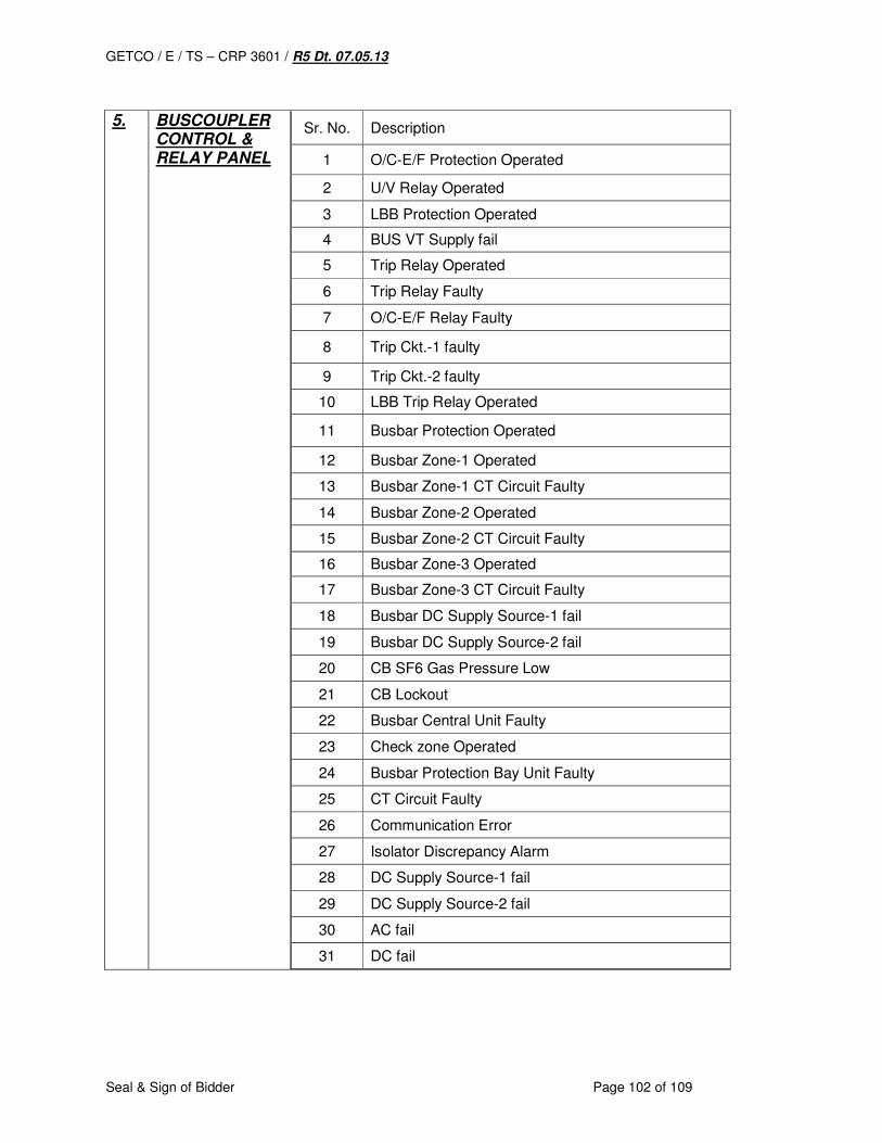
GETCO / E / TS – CRP 3601 / R5 Dt. 07.05.13
Seal & Sign of Bidder Page 102 of 109
5. BUSCOUPLER
CONTROL & RELAY PANEL
Sr. No. Description
1 O/C-E/F Protection Operated
2 U/V Relay Operated
3 LBB Protection Operated
4 BUS VT Supply fail
5 Trip Relay Operated
6 Trip Relay Faulty
7 O/C-E/F Relay Faulty
8 Trip Ckt.-1 faulty
9 Trip Ckt.-2 faulty
10 LBB Trip Relay Operated
11 Busbar Protection Operated
12 Busbar Zone-1 Operated
13 Busbar Zone-1 CT Circuit Faulty
14 Busbar Zone-2 Operated
15 Busbar Zone-2 CT Circuit Faulty
16 Busbar Zone-3 Operated
17 Busbar Zone-3 CT Circuit Faulty
18 Busbar DC Supply Source-1 fail
19 Busbar DC Supply Source-2 fail
20 CB SF6 Gas Pressure Low
21 CB Lockout
22 Busbar Central Unit Faulty
23 Check zone Operated
24 Busbar Protection Bay Unit Faulty
25 CT Circuit Faulty
26 Communication Error
27 Isolator Discrepancy Alarm
28 DC Supply Source-1 fail
29 DC Supply Source-2 fail
30 AC fail
31 DC fail
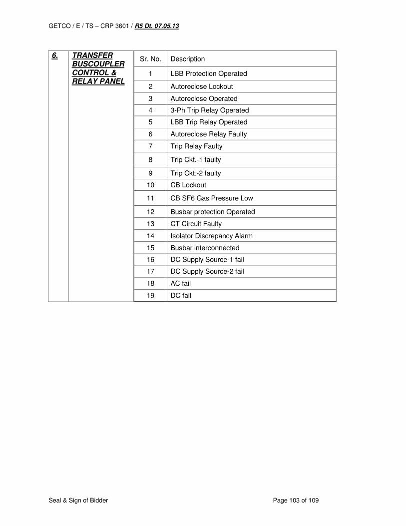
GETCO / E / TS – CRP 3601 / R5 Dt. 07.05.13
Seal & Sign of Bidder Page 103 of 109
6. TRANSFER
BUSCOUPLER CONTROL & RELAY PANEL
Sr. No. Description
1 LBB Protection Operated
2 Autoreclose Lockout
3 Autoreclose Operated
4 3-Ph Trip Relay Operated
5 LBB Trip Relay Operated
6 Autoreclose Relay Faulty
7 Trip Relay Faulty
8 Trip Ckt.-1 faulty
9 Trip Ckt.-2 faulty
10 CB Lockout
11 CB SF6 Gas Pressure Low
12 Busbar protection Operated
13 CT Circuit Faulty
14 Isolator Discrepancy Alarm
15 Busbar interconnected
16 DC Supply Source-1 fail
17 DC Supply Source-2 fail
18 AC fail
19 DC fail
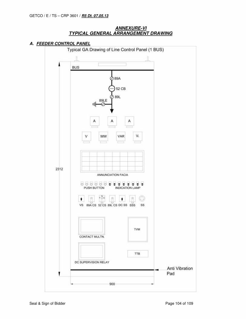
GETCO / E / TS – CRP 3601 / R5 Dt. 07.05.13
Seal & Sign of Bidder Page 104 of 109
ANNEXURE-VI TYPICAL GENERAL ARRANGEMENT DRAWING
A. FEEDER CONTROL PANEL
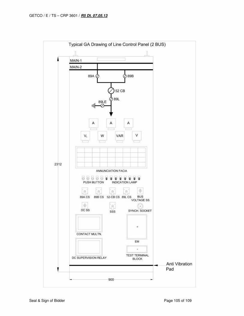
GETCO / E / TS – CRP 3601 / R5 Dt. 07.05.13
Seal & Sign of Bidder Page 105 of 109
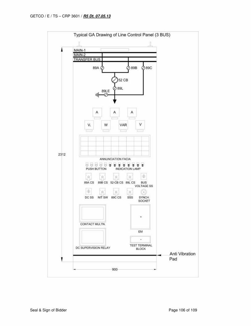
GETCO / E / TS – CRP 3601 / R5 Dt. 07.05.13
Seal & Sign of Bidder Page 106 of 109
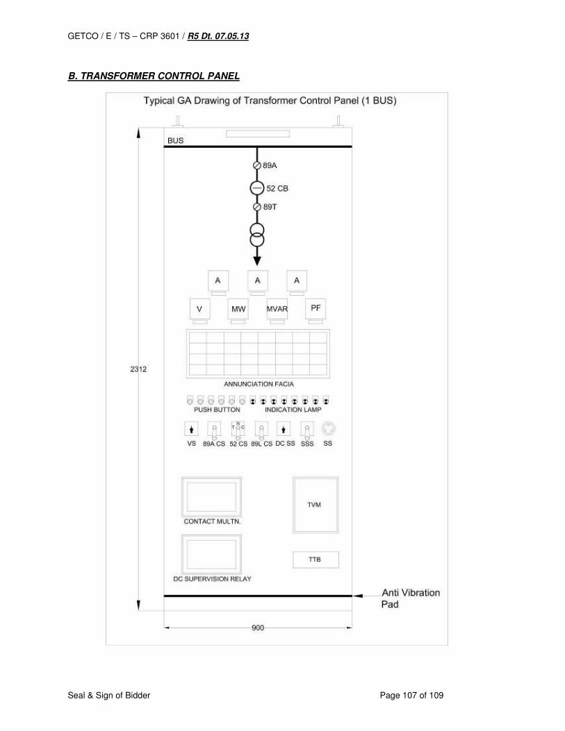
GETCO / E / TS – CRP 3601 / R5 Dt. 07.05.13
Seal & Sign of Bidder Page 107 of 109
B. TRANSFORMER CONTROL PANEL

GETCO / E / TS – CRP 3601 / R5 Dt. 07.05.13
Seal & Sign of Bidder Page 108 of 109
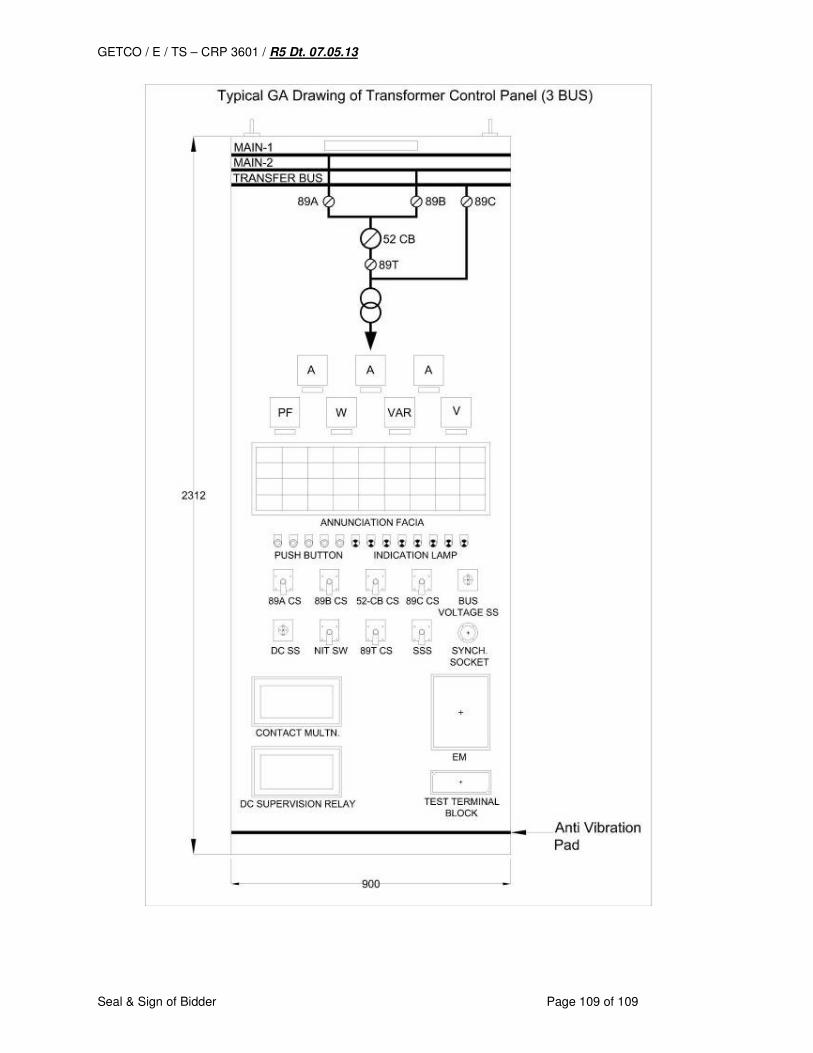
GETCO / E / TS – CRP 3601 / R5 Dt. 07.05.13
Seal & Sign of Bidder Page 109 of 109