gun flush box module 684019g - graco inc. flush box module 100 psi (0.7 mpa, ... installation 6 ......
TRANSCRIPT

Instructions – Parts List
�������������� ������������������������������
����������� �����������������������������������
Gun Flush Box� Module100 psi (0.7 MPa, 7 bar) Maximum Air Inlet Pressure
Part No. 570046
684019G
Read warnings and instructions.See page 2 for Table of Contents.

2 684019
Table of ContentsWarnings 3. . . . . . . . . . . . . . . . . . . . . . . . . . . . . . . . . . . . . . Introduction 5. . . . . . . . . . . . . . . . . . . . . . . . . . . . . . . . . . . . Installation 6. . . . . . . . . . . . . . . . . . . . . . . . . . . . . . . . . . . .
Typical Installation 6. . . . . . . . . . . . . . . . . . . . . . . . . . Ventilation 6. . . . . . . . . . . . . . . . . . . . . . . . . . . . . . . . . Location 6. . . . . . . . . . . . . . . . . . . . . . . . . . . . . . . . . . . Mounting 6. . . . . . . . . . . . . . . . . . . . . . . . . . . . . . . . . . Enclosed Waste Container 7. . . . . . . . . . . . . . . . . . . Grounding 7. . . . . . . . . . . . . . . . . . . . . . . . . . . . . . . . . Typical Installation Drawing 8. . . . . . . . . . . . . . . . . . Connect Tubing to the Pneumatic Controls 9. . . . .
Adjustments 10. . . . . . . . . . . . . . . . . . . . . . . . . . . . . . . . . . Lid Switch 10. . . . . . . . . . . . . . . . . . . . . . . . . . . . . . . . Gun Switch 10. . . . . . . . . . . . . . . . . . . . . . . . . . . . . . . Trigger Height 11. . . . . . . . . . . . . . . . . . . . . . . . . . . . . Gun Guide 12. . . . . . . . . . . . . . . . . . . . . . . . . . . . . . . .
Electric Controls 13. . . . . . . . . . . . . . . . . . . . . . . . . . . . . .
Setup 15. . . . . . . . . . . . . . . . . . . . . . . . . . . . . . . . . . . . . . . . PrecisionMix� II Controller Setup 15. . . . . . . . . . . . Gun Flush Box Controller 570262 Setup 15. . . . . . PrecisionMix Controller236323 or 949724 Setup 15. . . . . . . . . . . . . . . . . . . Programming Flow Chart for Gun Flush Box Controller 570262 16. . . . . . . . . . . . . . . . . . . . . . . . . Gun Flush Box Operation Logic 17. . . . . . . . . . . . .
Operation 18. . . . . . . . . . . . . . . . . . . . . . . . . . . . . . . . . . . . PrecisionMix� II Controller Operation 18. . . . . . . . . Gun Flush Box Controller 570262 Operation 18. .
Troubleshooting 22. . . . . . . . . . . . . . . . . . . . . . . . . . . . . . . Maintenance 23. . . . . . . . . . . . . . . . . . . . . . . . . . . . . . . . . . Parts 24. . . . . . . . . . . . . . . . . . . . . . . . . . . . . . . . . . . . . . . . Accessories 26. . . . . . . . . . . . . . . . . . . . . . . . . . . . . . . . . . Technical Data 27. . . . . . . . . . . . . . . . . . . . . . . . . . . . . . . . Graco Standard Warranty 28. . . . . . . . . . . . . . . . . . . . . . Graco Information 28. . . . . . . . . . . . . . . . . . . . . . . . . . . . .
684019 3
WARNINGFIRE, EXPLOSION, AND ELECTRIC SHOCK HAZARD
Improper grounding, poor air ventilation, open flames, or sparks can cause a hazardous condition andresult in fire, explosion, or electric shock, which can result in serious injury.
� Ground the equipment and the object being sprayed. See Grounding on page 7.
� Provide fresh air ventilation to avoid the buildup of flammable fumes from solvent or the fluid beingsprayed. Never operate the Gun Flush Box unless ventilation fans are operating.
� Extinguish all the open flames or pilot lights in the spray area.
� Do not smoke in the spray area.
� Keep the spray area free of debris, including solvent, rags, and gasoline.
� Do not turn on or off any light switch in the spray area while operating or if fumes are present.
� Do not operate a gasoline engine in the spray area.
� If there is any static sparking while using the equipment, stop spraying immediately. Identify andcorrect the problem.
Electrostatic Gun Safety� Do not flush the system with the gun electrostatics turned on.
� Interlock the gun turbine air supply to prevent operation of the power supply during flushing.
� Do not turn on the gun electrostatics until all solvent is removed from the system.
� When cleaning, flushing, or purging electrostatic equipment, use solvents that comply with yourlocal regulations. For countries following the U.S. National Fire Protection Association (NFPA) 33requirements, use solvents with a flash point higher than 100� F (38� C) or a solvent normallyused in spray operations. For European Countries complying with EN 50053, use solvents with aflash point as high as possible and higher than the ambient temperatures.
PRESSURIZED EQUIPMENT HAZARD
Spray from the gun, hose leaks, or ruptured components can splash fluid in the eyes or on the skinand cause serious injury.
� Do not bypass the Gun Flush Box interlock sensors. They prevent the Gun Flush Box from operat-ing unless the gun is in position and the door of the box is locked.
� Connect an interlock to prevent atomizing air from turning on during flushing.
� Do not stop or deflect fluid leaks with your hand, body, glove, or rag.
� Tighten all the fluid connections before operating the equipment.
� Check the hoses, tubes, and couplings daily. Replace worn, damaged, or loose parts immediately.Permanently coupled hoses cannot be repaired; replace the entire hose.

4 684019
WARNING
INSTRUCTIONS
EQUIPMENT MISUSE HAZARD
Equipment misuse can cause the equipment to rupture, malfunction, or start unexpectedly and resultin serious injury.
� This equipment is for professional use only.
� Read all instruction manuals, tags, and labels before operating the equipment.
� Use the equipment only for its intended purpose. If you are uncertain about usage, call your Gracodistributor.
� Do not alter or modify this equipment. Use only genuine Graco parts and accessories.
� Check the equipment daily. Repair or replace worn or damaged parts immediately.
� Do not exceed the maximum working pressure of the lowest rated system component. This equip-ment has a 100 psi (0.7 MPa, 7 bar) maximum air inlet pressure.
� Route the hoses away from the traffic areas, sharp edges, moving parts, and hot surfaces. Do notexpose Graco hoses to temperatures above 180�F (82�C) or below –40�F (–40�C).
� Use only Graco approved hoses.
� Use fluids or solvents that are compatible with the equipment wetted parts. See the Technical Datasection of all the equipment manuals. Read the fluid and solvent manufacturer’s warnings.
� Wear hearing protection when operating this equipment.
� Comply with all applicable local, state and national fire, electrical and other safety regulations.
TOXIC FLUID HAZARD
Hazardous fluids or toxic fumes can cause serious injury or death if splashed in the eyes or on theskin, swallowed, or inhaled.
� Know the specific hazards of the fluid you are using. Read the fluid manufacturer’s warnings.
� Store hazardous fluid in an approved container. Dispose of hazardous fluid according to all local,state and national guidelines.
� Wear the appropriate protective clothing, gloves, eyewear and respirator.

684019 5
IntroductionHow the Gun Flush Box Works
WARNINGFIRE, EXPLOSION, AND ELECTRICSHOCK HAZARDFor Electrostatic Guns: To reduce therisk of fire, explosion, or electric shock:
� In addition to following the warningson page 3, read your electrostaticgun manual for additional warningsand instructions on the safe use of anelectrostatic gun. If you do not have acopy of this manual, please contactyour local Graco distributor.
� Always turn off the electrostatics before placingthe gun in the Gun Flush Box and whenever youstop spraying.
WARNINGFIRE AND EXPLOSION HAZARDIn multiple gun systems: For yoursafety, each gun must be used only withits corresponding Gun Flush Box for theinterlocks to work. For example: With atwo gun system, placing gun #1 into Gun
Flush Box #2 will shut off the atomization air forgun #2 and leave the atomization air on for gun #1during purging.
FeaturesWhen used with a PrecisionMix or a PrecisionMix IIsystem, the Gun Flush Box operates with a controllerto automatically flush manual guns into an enclosedwaste container. The advantages of using the GunFlush Box instead of conventional flushing methodsinclude:
� Reduced solvent use� Reduced VOC (volatile organic compounds) emis-
sions� Improved operator safety during flushing
The Gun Flush Box controller flushes the exact amountof solvent required to clean the system. It reducesVOCs by preventing solvent from being atomizedduring the flush cycle.
Traditional flushing procedures expose the operator toatomized solvent and accidental gun discharge. TheGun Flush Box contains the solvent and preventsaccidental gun triggering with safety interlocks.
The interlocks will only allow atomizing air to the gunwhen the gun is out of the Gun Flush Box and the doorof the box is closed. If a switch fails or if system air isshut off, the atomizing air will be shut off to the gun.
OperationNOTE: If using an electrostatic gun, the operator mustturn off the electrostatics before placing the gun in thebox.
The operator places the gun in the Gun Flush Box andcloses the door. The Gun Flush Box interlocks turn offthe atomizing air to the gun to prevent the solvent frombeing atomized and to ensure a PRO� gun electro-static turbine will be off when the operator starts flush-ing.

6 684019
InstallationTypical Installation
Refer to the typical installation drawing in Fig. 4, page8, as a guide for installing the Gun Flush Box. Contactyour Graco distributor for an actual system design.
Ventilation
WARNINGTOXIC OR FLAMMABLE FUMESHAZARDTo avoid hazardous concentrations offlammable or toxic fumes, install the GunFlush Box in a properly ventilated spraybooth. Never operate the Gun Flush Boxunless ventilation fans are operating.
Electrically interlock the Gun Flush Box air supply withthe ventilators to prevent the box from operating whenventilating fans are not operating. Check and follow allNational, State, and Local codes regarding air exhaustvelocity requirements.
Location
Locate the Gun Flush Box in an area easily accessibleto the operator and away from the spray or applicationpoint, to help avoid getting over-spray on it.
Mounting
The Gun Flush Box can be wall, stand, or drum moun-ted in the spray booth. Install the gun flush box(es),using the mounting holes as a template. See Fig. 1 fordimensions. Make sure the mounting surface willwithstand the weight of the Gun Flush Box, hoses, andthe stress of operation.
Depth: 9 in.(229 mm)
Fig. 1
14 in.(356 mm)
9 in.(229 mm)
684019 7
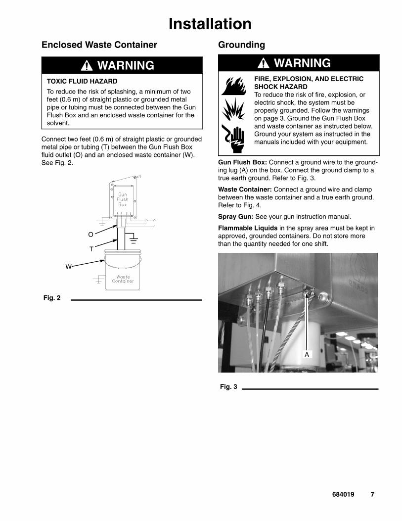
InstallationEnclosed Waste Container
WARNINGTOXIC FLUID HAZARD
To reduce the risk of splashing, a minimum of twofeet (0.6 m) of straight plastic or grounded metalpipe or tubing must be connected between the GunFlush Box and an enclosed waste container for thesolvent.
Connect two feet (0.6 m) of straight plastic or groundedmetal pipe or tubing (T) between the Gun Flush Boxfluid outlet (O) and an enclosed waste container (W).See Fig. 2.
Fig. 2
O
T
W
Grounding
WARNINGFIRE, EXPLOSION, AND ELECTRICSHOCK HAZARDTo reduce the risk of fire, explosion, orelectric shock, the system must beproperly grounded. Follow the warningson page 3. Ground the Gun Flush Boxand waste container as instructed below.Ground your system as instructed in themanuals included with your equipment.
Gun Flush Box: Connect a ground wire to the ground-ing lug (A) on the box. Connect the ground clamp to atrue earth ground. Refer to Fig. 3.
Waste Container: Connect a ground wire and clampbetween the waste container and a true earth ground.Refer to Fig. 4.
Spray Gun: See your gun instruction manual.
Flammable Liquids in the spray area must be kept inapproved, grounded containers. Do not store morethan the quantity needed for one shift.
Fig. 3
A

8 684019
InstallationTypical Installation of Gun Flush Box in PrecisionMix System
Fig. 4

684019 9
InstallationConnect Tubing to the Pneumatic Controls
Fig. 5 shows the bottom of the Gun Flush Box. Thefour bulkhead fittings are labeled:
P = Supply air inA = Return air (for the gun in the box)C = Gun trigger cylinders air (activates the gun trigger)S = Safety interlock (locks out the atomizing air)
See Fig. 6 for detailed information on the Gun FlushBox internal pneumatics.
Fig. 5
BOTTOM VIEW
1. Connect a 5/32” (4 mm) OD tube between the airsupply and the P bulkhead. Use a clean, dry airsupply; filtered to 10 microns.
WARNINGEQUIPMENT MISUSE HAZARDDo not exceed 100 psi (0.7 MPa, 7 bar)maximum air pressure.
INSTRUCTIONS
2. Connect a 5/32” (4 mm) OD tube between the Abulkhead and the return air input on the controller.See Fig. 6.
3. Connect a 5/32” (4 mm) OD tube between Cbulkhead and the gun trigger solenoid output onthe solenoid box or the Gun Flush Box control box.See Fig. 6.
Fig. 6
A
TYPICAL TWO-GUN PNEUMATIC SCHEMATIC
10 684019
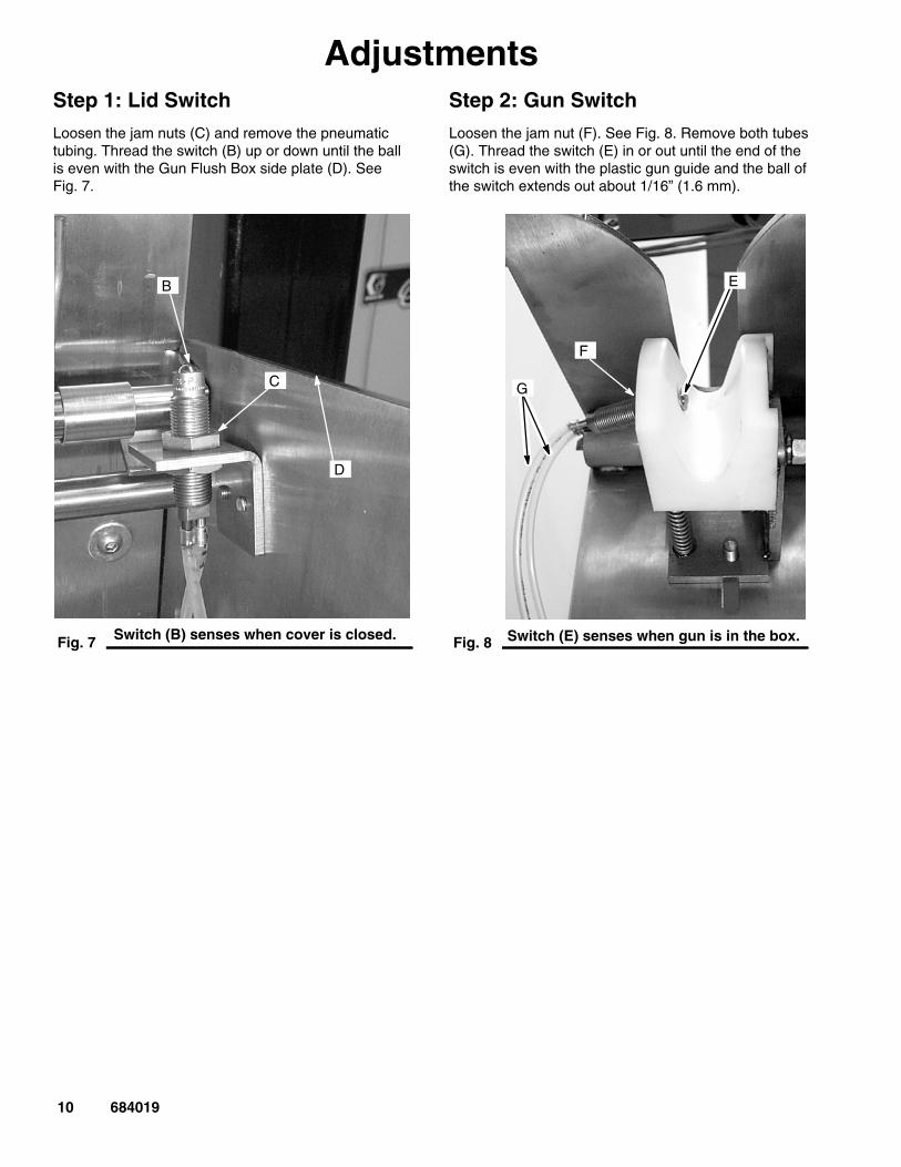
AdjustmentsStep 1: Lid Switch
Loosen the jam nuts (C) and remove the pneumatictubing. Thread the switch (B) up or down until the ballis even with the Gun Flush Box side plate (D). SeeFig. 7.
Fig. 7
B
C
D
Switch (B) senses when cover is closed.
Step 2: Gun Switch
Loosen the jam nut (F). See Fig. 8. Remove both tubes(G). Thread the switch (E) in or out until the end of theswitch is even with the plastic gun guide and the ball ofthe switch extends out about 1/16” (1.6 mm).
Fig. 8
E
F
G
Switch (E) senses when gun is in the box.

684019 11
AdjustmentsStep 3: Trigger Height
Follow this procedure to ensure the gun triggers prop-erly during a purge.
1. Insert the gun into the Gun Flush Box.
2. Force the cylinder triggers on by connecting air tothe C bulkhead (K). See Fig. 9. Turn on the air toextend both cylinders.
3. Loosen both screws (L) on the side of the box. SeeFig. 10.
Fig. 9
K
Fig. 10
L
4. Raise the gun holder (M) until the pin (N) opensthe trigger. See Figs. 11 and 12.
NOTE: Inside the gun flush box are markings for thePRO� 3500, PRO� 4500, and Air Spray Guns. Thesemarkings are only general guidelines of where toposition the gun holder.
Fig. 11
M
Fig. 12
N

12 684019
AdjustmentsStep 4: Gun GuideFollow this procedure to ensure the gun guide isadjusted so the door will close completely when thegun is in the box.
1. Insert the gun into the box.
2. Loosen the screws (J) on top of the door, then fullyclose the door. See Fig. 13.
3. Slide the gun guide forward to fit snugly against thegun body.
4. Mark the location of the screws (H), then tightenthe screws (J) in the new location. See Fig. 14.
5. Make sure the gun is secure. If the gun guide isproperly adjusted, the gun should not move easilyfrom side to side.
Fig. 13
J
Fig. 14
H
684019 13
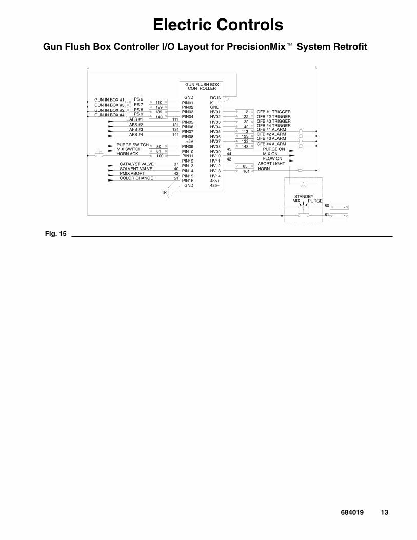
Electric ControlsGun Flush Box Controller I/O Layout for PrecisionMix� System Retrofit
Fig. 15
STANDBYMIX PURGE
80
81
112122132142113123133143
GFB #1 TRIGGERGFB #2 TRIGGERGFB #3 TRIGGERGFB #4 TRIGGERGFB #1 ALARMGFB #2 ALARMGFB #3 ALARMGFB #4 ALARM
PURGE ONMIX ONFLOW ON
ABORT LIGHTHORN
85101
454443
GUN FLUSH BOXCONTROLLER
GNDPIN01PIN02PIN03PIN04PIN05PIN06PIN07PIN08
+5VPIN09PIN10PIN11PIN12PIN13PIN14PIN15PIN16
GND
DC INKGNDHV01HV02
HV04HV05HV06HV07HV08HV09HV10HV11HV12HV13HV14485+485–
HV03
110129139140 111
121131141
PS 6PS 7PS 8PS 9
AFS #1AFS #2AFS #3AFS #4
GUN IN BOX #1
GUN IN BOX #2GUN IN BOX #3
GUN IN BOX #4
8081100
PURGE SWITCHMIX SWITCHHORN ACK
CATALYST VALVESOLVENT VALVEPMIX ABORTCOLOR CHANGE
37404251
1K
14 684019
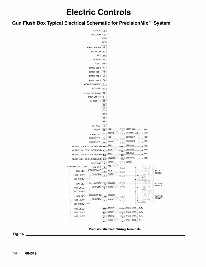
Electric ControlsGun Flush Box Typical Electrical Schematic for PrecisionMix� System
DC COMM
���� �!���
DC COMM
DC COMM
"����� �!���
Fig. 16
6
8
SPARE
SPARE
42
43
44
45
46
47
48
49
50
51
52
53
54
55
56
57
58
59
60
6
38
37
39
40
112
122
132
142
8
6
62
8
65
8
68
8
111
121
131
141
+24VDC
RATIO ALARM
FLOW ON
MIX
PURGE
RATIO BIT 0
RATIO BIT 1
RATIO BIT 2
RATIO BIT 3
COLOR CHANGE
POTLIFE
HIGH/LOW FLOW
TANK EMPTY
RATIO BIT 4
+24 VDC
RESIN
CATALYST
SOLVENT A
SOLVENT B
GUN FLUSH BOX 1 SOLENOID
DC COMM
+24 VDC
�� #� �!���
DC COMM
FLOW METER CARD
RES SIG
NOT USED
DC COMM
CAT SIG
NOT USED
DC COMM
SOL SIG
NOT USED
DC COMM
NOT USED
NOT USED
NOT USED
"�$
�"���
"�$
!%���
"�$
& '�
"�$
(� �!
& ��)
"�$
& '�
& ��)
�"����
& ��)
(� �!
& ��)
&"�!�
& ��)
�"���
& ��)
"������
���� (����
�� #����
�� #���&
��&���
��&*��
��&+��
��&,��
"�$
"�$
"�$
"�$
"�$
"�$
"�$
"�$
& ��)
111
121
131
141
"���������"
���� (�������"
�� #��������"
& )
& )
& )
& )
�"�
�"�
�"�
�"�
���-�
���-*
���-+
���-,
+
+.
+�
,�
�/�
�/*
�/+
�/,
0
0*
01
0
PrecisionMix Field Wiring Terminals
GUN FLUSH BOX 2 SOLENOID
GUN FLUSH BOX 3 SOLENOID
GUN FLUSH BOX 4 SOLENOID

684019 15
SetupPrecisionMix� II Controller Setup
See your PrecisionMix II system manual 308916 forsetup instructions.
Gun Flush Box Controller570262 Setup
See Fig. 17 for the programming flow chart.
See Fig. 15 for wiring details of a typical Gun FlushBox controller.
Time Date Set: Program the desired time and date.
Potlife Time Left: View the remaining potlife at eachgun being used.
Potlife Setup Pot Time: Enter the desired potlife timein from 2 minutes to 999 minutes.Default = 30 minutes
Potlife setup warning time: Set a warning time from 0to 10 minutes to sound an optional audible alarmbefore the actual potlife time expires. This alarm willonly sound if the gun with mixed material is not in theGun Flush Box.Default = 0 minutes
Guns Setup – No. of Guns: Specify the total numberof guns used in the system.Default = 1 gun
Fill Volume Setup Mixer Size: Enter the static mixervolume.Default = 50 cc
Fill Volume Setup G1 Fill Volume: Enter the volumeof fluid from the static mixer to the gun. This valuedetermines the amount of material that will dispense tothe gun during the fill sequence. Guns 1–4 each havea user specified fill volume.Default = 50 cc
GFB Flush Box Operation Setup Auto Operation:Enables the Gun Flush Boxes when ON is selected.When OFF is selected, the controller will functionnormally without the Gun Flush Box operation.Default = ON
GFB Operation Setup CC Autofill: When ON isselected, the guns will automatically reload a new colorafter flushing and color change are completed. WhenOFF is selected, the operator switch must be turned tothe MIX position after a color change to load the newcolor to the guns. See page 20 for the color changesequence.Default = OFF
Input/Output Test BK1DG: View the status of inputs1–8. 1 = ON and 0 = OFF.
Input/Output Test BK2DG: View the status of inputs9–16. 1 = ON and 0 = OFF.
Input/Output Test Out: Test the output functions.1 = ON and 0 = OFF.
Warning: When this screen displays, normal operationis disabled.
PrecisionMix� Controller 236323 or949724 Setup
NOTE: For more information about the PrecisionMixsystem, see your PrecisionMix manual 308344 or684029.
1. Boot the PrecisionMix controller for color changeand separate alarms.
2. Set the PrecisionMix potlife with the pendant to themaximum limit of 999 minutes. The Gun Flush Boxcontroller pot life time will override this value.

16 684019
Po
tlife
Se
tup
Po
t Tim
e =
XX
X
Po
tlife
se
tup
Wa
rnin
g T
ime
= X
XX
XX
Fill
Vo
lum
e S
etu
pM
ixe
r S
ize
= X
XG
un
s S
etu
pN
o.o
f G
un
s =
X
En
ter
Po
tlif
e ti
me
r
in m
inu
tes
(2–9
99)
En
ter
the
tota
l
gu
ns
us
ed
in s
ys
tem
Se
lec
t th
e C
olo
r
Ch
an
ge
Au
toF
ill
Op
tio
n O
N/O
FF
En
ter
the
sta
tic
mix
er
siz
e (c
c)
GF
B S
etu
p R
ev:
1.0
1A
uto
Op
er.
= X
XX S
ele
ct t
he
Au
to
Op
era
tio
n O
N/O
FF
Fill
Vo
lum
e S
etu
pG
1 F
ill V
ol=
XX
XX
X
En
ter
the
ho
se
fill
vo
lum
e fr
om
Sta
tic
Mix
er
to g
un
1 o
r
de
sir
ed
fill
am
ou
nt (
cc
)
Fill
Vo
lum
e S
etu
pG
2 F
ill V
ol=
XX
XX
X
En
ter
the
ho
se
fill
vo
lum
e fr
om
Sta
tic
Mix
er
to g
un
2 o
r
de
sir
ed
fill
am
ou
nt (
cc
)
Fill
Vo
lum
e S
etu
pG
3 F
ill V
ol=
XX
XX
X
En
ter
the
ho
se
fill
vo
lum
e fr
om
Sta
tic
Mix
er
to g
un
3 o
r
de
sir
ed
fill
am
ou
nt
(cc
)
Fill
Vo
lum
e S
etu
pG
4 F
ill V
ol=
XX
XX
X
En
ter
the
ho
se
fill
vo
lum
e fr
om
Sta
tic
Mix
er
to g
un
4 o
r d
es
ire
d
fill a
mou
nt (
cc)
GF
B S
etu
p R
ev:
1.0
1C
C A
uto
Fill
= X
XX
En
ter
the
Po
tlif
e
Wa
rnin
g T
ime
In
min
ute
s (0
–1
0)
Tim
e D
ate
Se
t
da
te01
–15–
98E
nte
r s
Sy
ste
m D
ate
Tim
e D
ate
Se
t
tim
e0
9:4
9:5
6
Inp
ut/
Ou
tpu
t Te
stB
K1
DG
00
00
00
00
Sta
tus
of i
np
ut 1
–8
Inp
ut/
Ou
tpu
t Te
stB
K2
DG
00
00
00
00
Sta
tus
of i
np
ut 9
–1
6
Inp
ut/
Ou
tpu
t Te
stO
ut 0
00
00
00
00
00
00
0
Sta
tus
of o
utp
ut 1
–1
4.
Us
e fi
eld
, up
or
do
wn
ke
y to
fo
rce
ou
tpu
t
ON
/OF
F.
ITE
MIT
EM
ITE
M
ITE
M
ITE
M
ITE
MIT
EM
ITE
M
ITE
M
ME
NU
ME
NU
ME
NU
ME
NU
ME
NU
Po
tlife
Tim
e L
eft
GF
B1
=X
XX
XX
Gu
n F
lus
h B
ox
#1
po
tlif
e ti
me
left
in
se
co
nd
s
Po
tlife
Tim
e L
eft
GF
B2
=X
XX
XX
Gu
n F
lus
h B
ox
#2
po
tlif
e ti
me
left
in
se
co
nd
s
Po
tlife
Tim
e L
eft
GF
B3
=X
XX
XX
Gu
n F
lus
h B
ox
#3
po
tlif
e ti
me
left
in
se
co
nd
s
Po
tlife
Tim
e L
eft
GF
B4
=X
XX
XX
Gu
n F
lus
h B
ox
#4
po
tlif
e ti
me
left
in
se
co
nd
s
ITE
M
ITE
M
ITE
M
ME
NU
ME
NU
ITE
M
ITE
M
ITE
M
ITE
M
ITE
M
ITE
M
Men
u–
Men
u K
ey T
oggl
es b
etw
een
Set
–up
Par
amet
ers
– Ite
m K
ey T
oggl
es w
ithin
a S
et–u
p P
aram
eter
– F
ield
Key
is u
sed
to s
crol
l fro
m le
ft to
rig
ht w
ithin
a d
ata
entr
y sc
reen
– U
p/D
own
Key
s ar
e us
ed to
cha
nge
sele
cted
dat
a fie
ld.
– U
se H
elp
Key
for
furt
her
expl
anat
ion
Item
Fiel
d
Hel
p
Fig. 17
Programming Flow Chart for GunFlush Box Controller 570262
En
ter
sS
ys
tem
Tim
e

684019 17
(Gu
n tr
igg
ere
d&
ca
taly
st O
N)
or
au
to–
loa
d O
N?
Gu
n p
otl
ife
tim
er
sta
rts
Gu
n p
otl
ife
tim
er
tim
eo
ut?
Gu
n tr
igg
ere
d m
ore
tha
n 4
0 s
ec
?
Re
set g
un
po
tlif
e ti
me
r
Are
all
of t
he
gu
ns
wit
h m
ixe
dm
ate
ria
l lo
ad
ed
in g
un
flu
sh
bo
xe
s?
So
un
d o
pti
on
al
ho
rn u
nti
l all
gu
ns
(wit
h
loa
de
d m
ate
ria
l)a
re in
gu
n fl
ush
bo
xe
s.
Fla
sh
ala
rm l
igh
t un
til
do
ne
. P
urg
e g
un
s (w
ith
mix
ed
ma
teri
al)
in o
rde
rfr
om
gu
n 1
to g
un
4
YE
S
YE
S
NO
NO
YE
S
YE
S
Aft
er
pu
ttin
gg
un
s in
bo
xe
s,
op
era
tor
pu
tsu
nit
in
”PU
RG
E”
mo
de
Fla
sh
ala
rm l
igh
t un
til
do
ne
. P
urg
e g
un
s (w
ith
mix
ed
ma
teri
al)
in o
rde
rfr
om
gu
n 1
to g
un
4
Op
era
tor
pu
tsu
nit
in
”MIX
”m
od
e
So
un
d h
orn
un
til
all
gu
ns
(wit
hm
ixe
d m
ate
ria
l)a
re in
th
e b
ox
an
d fl
as
h a
larm
ligh
t.
Co
lor
Ch
an
ge
au
tofi
ll is
se
tto
ON
an
d th
eC
C i
np
ut i
sO
N d
uri
ng
pu
rge
cy
cle
Po
tlif
e
Wa
rnin
gO
pti
on
is s
et
O t
o 1
0 m
in.
Is g
un
po
tlif
eti
me
r le
ss t
ha
ns
pe
cif
ied
wa
rnin
gti
me
?
So
un
d h
orn
un
til
tim
er
is r
ese
t.(I
f gu
n is
ou
t of
bo
x)
Gu
n1
trig
ge
red
mo
reth
an
40
se
c?
YE
S
YE
S
PO
TL
IFE
MA
NU
AL
PU
RG
EL
OA
D P
AIN
TC
C A
UT
OF
ILL
PO
TL
IFE
WA
RN
ING
If g
un
1 is
in
bo
x, t
he
nlo
ad
pa
int t
o g
un
1 (f
or
the
am
ou
nt s
et f
or
G1
fill
vo
lum
e)
If t
he
re is
mo
re t
ha
n 1
gu
n in
th
e s
ys
tem
, th
eu
nit
wil
l lo
ad
pa
int t
o th
ere
ma
inin
g g
un
s
Re
se
t gu
n1
po
tlif
e ti
me
r
Aft
er
do
ne
pu
rgin
g, t
he
un
it lo
ad
s p
ain
t to
gu
n1
(fo
r th
e a
mo
un
t se
t fo
rG
1 fi
ll vo
lum
e)
If t
he
re is
mo
re t
ha
n 1
gu
n in
th
e s
ys
tem
, th
eu
nit
wil
l lo
ad
pa
int t
o th
ere
ma
inin
g g
un
s
Tim
er
Co
nti
nu
es
No
No
, Go
to P
otl
ife
Fig. 18
Gun Flush Box Operation Logic

18 684019
OperationPrecisionMix� II Controller Operation
See your PrecisionMix II system manual 308916 for operation instructions.
Gun Flush Box Controller 570262 Operation
Operating Checklist.
Check the following list daily, before starting to operatethe system, to help ensure safe, efficient operation.
____ 1. All operators are properly trained to safelyoperate the system.
____ 2. If using electrostatics, all operators are prop-erly trained to safety operate an electrostaticspray system. Operators must always turn offthe electrostatics (P) before placing the spraygun in the Gun Flush Box. See Fig. 19.
____ 3. The system is thoroughly grounded and theoperator and all persons entering the sprayarea are properly grounded. See Grounding,page 7.
____ 4. The ventilation fans are operating properly.
____ 5. All the debris, including flammable liquids,rags, and non-essential equipment, is re-moved from the spray area.
____ 6. All flammable liquids in the spray booth are inapproved, grounded containers.
____ 7. All electrically conductive objects in the sprayarea, including paint containers; Gun FlushBoxes; and wash cans, are electricallygrounded and the floor of the spray area iselectrically conductive and grounded.
Fig. 19
P

684019 19
OperationGun Flush Box Controller 570262 Operation (continued)
NOTE: The following instructions are not for use with the PrecisionMix II system. See your PrecisionMix II systemmanual 308916 for operation instructions.
Single Gun Flush Box
General
1. Complete the operating checklist.
2. If cleaning an electrostatic gun, turn off the electro-statics (P). See Fig. 20.
Fig. 20
P
3. Open the Gun Flush Box door. Place the gun (Q) inthe box and close the door. See Figs. 21 and 22.
WARNINGFIRE AND EXPLOSION HAZARDFor Electrostatic Guns: To reduce therisk of fire, explosion, or electric shock,always turn off the electrostatics on anelectrostatic gun before placing the gunin the Gun Flush Box.
Resetting Alarms
To reset an alarm when the alarm light is solid red, turnthe Operator Station switch from MIX to STANDBY.See Fig. 23. See Troubleshooting, page 22.
Fig. 21
Q
Fig. 22
To reset an alarm when the alarm light is flashing (potlife alarm), follow the Pot Life Monitor and Alarmprocedure, page 21.
NOTE: The first three PrecisionMix alarms will be resetby the Gun Flush Box controller to prevent nuisancealarms during flushing and loading.

20 684019
OperationGun Flush Box Controller 570262 Operation (continued)
NOTE: The following instructions are not for use with the PrecisionMix II system. See your PrecisionMix II systemmanual 308916 for operation instructions.
Purging the System
1. Follow the General Operation instructions onpage 19.
2. Turn the Operator Switch to PURGE. The redalarm light will flash on and off until the purge iscomplete.
3. When the alarm light stops flashing, turn the Oper-ator Switch to STANDBY.
Typical Remote Operator Station
STANDBY
MIX PURGE
Fig. 23�����
Alarm Light
OperatorSwitch
Loading the Material
1. Follow the General Operation instructions onpage 19.
2. Turn the Operator Switch to MIX.
3. The red alarm light will flash on and off until apreset amount of mixed material is loaded throughthe gun.
4. When the alarm light stops flashing, turn the Oper-ator Switch to STANDBY.
5. When ready to spray, remove the gun from theGun Flush Box and close its door.
6. Turn the Operator Switch to MIX to start spraying.
NOTE: The Gun Flush Box door must be closed for theatomizing air valve to open.
Color Change
Steps 2 to 5 must be completed within the set purgesequence time or the old color may be reloaded or thePrecisionMix may have an I/O error. The operator canturn the color change autofill option OFF on the GunFlush Box controller. With this option off, the operatorcan fill the guns by turning the Operator Switch to MIXafter the color change is complete.
1. Follow the General Operation instructions onpage 19.
2. Turn the Operator Switch to PURGE. The redalarm light will flash on and off until the purge iscomplete.
3. While the unit is purging, turn the solvent switchON and then press the dump valve on the colorchange control box.
4. After the old resin dumps through the valve, selectthe new color, then turn the solvent switch to OFF.
5. Press the dump valve again to load the new colorfrom the color stack to the PrecisionMix manifold.
6. The Gun Flush Box controller will purge the mixedmaterial and load the new color to a preset vol-ume.
7. When the alarm light stops flashing, turn the Oper-ator Switch to STANDBY.
8. When ready to spray, remove the gun from theGun Flush Box and close its door.
NOTE: The resin dump valve must be activated toautomatically load the new color.
9. Turn the Operator Switch to MIX to start spraying.
NOTE: The Gun Flush Box door must be closed for theatomizing air valve to open.
684019 21
OperationGun Flush Box Controller 570262 Operation (continued)
NOTE: The following instructions are not for use with the PrecisionMix II system. See your PrecisionMix II systemmanual 308916 for operation instructions.
Pot Life Monitor and Alarm
NOTE: Pot life timer at each gun is reset when thesystem controller senses an air flow signal (typically anair flow switch) for 40 seconds.
1. Insert the gun into the Gun Flush Box and closethe door when the gun is not in use.
2. If the gun has mixed material in it, the Gun FlushBox controller will start the pot life timer. When theset time ends, the Gun Flush Box will automaticallypurge the mixed material.
3. If the gun is inactive but not in the Gun Flush Box,the box controller will activate the alarm light so thelight is flashing.
4. Place the gun in the Gun Flush Box and close thedoor. The Gun Flush Box controller will open thegun and activate the purge sequence.
5. When the light stops flashing, purging is complete.Reload the material by moving the Operator Switchmomentarily to PURGE (for less than 2 seconds)then back to MIX.
NOTE: If you want a warning signal before the pot lifetime ends, a warning signal of 1 to 10 minutes can beprogrammed into the gun flush box controller. See theProgramming Flow Chart on page 16.
The warning output signals can be wired to optionalhorns or lights to signal that the potlife timer value isless than the specified warning time and a gun withmixed material is out of the box. Within the specifiedwarning time, the operator can either:
� Reset the pot life timer by triggering the gun fora total of 40 seconds or
� Put the gun back in the Gun Flush Box andwait for the automatic purge.
Multiple Gun Operation
Follow the same single gun operating instructions onpages 19 to 21, taking note of the following additionalinformation:
� Guns will be loaded and purged in sequential order(gun 1, gun 2, gun 3, etc.). The sequence dependson which guns are in their box at the start of a fillcycle.
� During the automatic purge cycle, only guns withmixed material loaded will be purged.
� Manual purge will only purge guns which are in theirbox. Manual purge will not start until all guns withmixed material are in their box.
� Automatic purge will not start until all guns withloaded material are in their box. Operators shouldput the guns in their box with the door closed when-ever they finish spraying.
� If a gun or guns are being taken out of the line forservice (by valve shutoff or other means), one ofthe following things must occur to prevent the gunflush box controller from trying to fill these gunsduring the mix/fill mode.
� Leave the gun in the box, but leave the doorpartially open or
� Take the gun out of the box completely.
NOTE: Purge the gun(s) before taking them out of theline for service.

22 684019
TroubleshootingProblem Cause Solution
Gun is in the Gun Flush Box, but Air is shut off. Turn on the air to the system.,the system will not purge or mix. Gun switch is not activating. Test the switch. Replace it if it is dam-
aged.
Operator switch is not wired properly. Check the I/O to see if the properinput is activating. Rewire the switchif necessary.
Tubing is not installed correctly. Check tubing against schematic onpage 9.
Gun Flush Box fails to purge afterthe pot life time ends.
Gun is not in Gun Flush Box. Place the gun in the Gun Flush Boxwhen it is not in use.
Gun switch is not activating. Test the switch. Replace it if it is dam-aged.
PrecisionMix pot life timer not set at999 minutes.
Set PrecisionMix pot life timer to 999minutes
PrecisionMix alarms not separate andpot life is activating Relay 6 on Preci-sionMix I/O board.
Boot system for separate alarms. SeePrecisionMix manual.
Gun trigger is not open when theGun Flush Box controller acti-
Tubing is not installed correctly. Check tubing against schematic onpage 9.
vates it. Cylinder is damaged. Clean cylinder rod or replace.
Gun is not properly set in the gunholder.
Check to make sure the gun holder isnot obstructed by buildup.
Lower cylinder is out of adjustment. Adjust the block as instructed in Trig-ger Height adjustment procedure onpage 11.
Gun is out of the Gun Flush Boxwith the door closed but the atom-
Lid switch or gun switch failure. Check the switches and replace ifnecessary.
izing air is off. No air flow to the Gun Flush Box. Check the air supply and tubing.

684019 23
MaintenanceDaily Weekly Every two weeks,
minimum
Gun Flush BoxEnclosure
Keep the inside as clean aspossible. Clean with a com-patible solvent.
Clean the inside and out-side of the enclosure with acompatible solvent.
Door Keep hinge holes as cleanas possible.
Grease hinges.
Cylinders Pull the cylinder rod for-ward and coat with greaseor petroleum jelly.
Switches Clean and lubricate.
Fluid Outlet tube Check for buildup of mixmaterial and replace if re-stricted.

24 684019
Parts
1
3
4
2
8862A
63
NOTE: Grease all cylinders and sensors with grease.
Insert washer before greasing axle
Grease
Loctite
Optional Gun Holder shown; not included with assembly. Selection of correct gun holder required for proper operation.
1 60
14
5
7
28
25, 26
65 2
2025, 26
23
9
4057143551
37363517
41
3216
2739
33 18 2
50 51
10
29
3
2
21 335363743
82
57
40
2526
62
348
4
54 2
15 11 31
41
30REF2739
2
3723
1
4
6
30
373635 45
3524
12
42
66
68
67
70

684019 25
PartsRef.No.
Part No. Description Qty.
1 626487 PANEL, cabinet 22 626488 ROD, connecting 43 626489 COVER, cylinder 14 626490 WRAPPER, cabinet 15 626491 COVER, cabinet 16 626492 BRACKET, mounting 17 626493 BRACKET, guide 18 626494 GUIDE, hand gun 19 626495 KNOB, latch 210 626496 PIN, latch 211 626497 SUPPORT, cover 112 626498 BEARING, support 114 626500 ROD, connecting 115 551890 NUT, jam, hex, 3/8–24 116 626502 SUPPORT, cover 117 626503 BRACKET, support 118 626504 BUTTON, cylinder 120 626506 PLATE, cover 121 626507 PIN, 1/4–20 x 2.25 223 551785 SCREW, cap, 5/16 x 3/4 424 551786 SCREW, cap, 5/16 x 2 125 551787 SCREW, cap, 10–32 x 5 1026 551788 WASHER, lock, split, #10 1027 551789 SCREW, cap, 3/8 x 1 1028 551790 SPRING, torsion, 90� 129 551791 SPRING, compression, lid 230 551965 SCREW, cap, 5/16 x 1.5 431� 551793 CYLINDER, air, 0.438 dia. 132 551794 CYLINDER, air, 0.568 dia. 133 551795 NUT, hex head, 7/16–20 135 104034 WASHER, plain 736 108946 NUT, hex, 5/16–18 437 107542 WASHER, lock, split, 51/6 639 103975 WASHER, lock, 3/8 10
Ref.No.
Part No. Description Qty.
40� 551775 VALVE, limit, pneumatic,w/spring return
2
41 514581 CONNECTOR, 5/32” tube x10–32
2
42 551773 CONNECTOR, bulkhead,5/32” OD
4
43 626509 SPACER, gun support 145 626517 AXLE, support 148 222011 CLAMP, grounding 150 551731 TUBE, 5/32 OD, polyethyl-
ene, white�
51 551805 SCREW, cap, socket head,5/16–18 x 1.750
3
54� 626523 BUTTON, cylinder 155 514896 TEE, 3-way, 5/32 OD (m x f) 157 551816 NUT, jam, 12m 360 551891 WASHER, 21/32 ID x 7/8
OD2
62 102556 RIVET 263 551849 GROMMET, 5/16 ID x 1/2
OD1
65 551892 BRACKET, mount, electro-static switch
1
66 502526 VALVE, air, 3-way, springreturn
1
67 598140 ELBOW, 5/32 tube 1-1/8npt(m)
1
68 501014 ACTUATOR, air, 1/8 npt(f) 170 598141 TEE, 5/32 tube x 1/8 npt 171 551908 SCREW, cap, 10–32 x
1-1/4”1
74 180233 LABEL, warning, pinch point 2
� Order length needed.
� Keep these spare parts on hand to reduce downtime.

26 684019
AccessoriesGun Holder
Part No. For Gun
570296 Graco Delta Spray� Gun
626518 Graco AA Gun with RAC Tip
626540 Graco AA 200 HS Gun
626508 Graco Manual PRO� Gun
626571 Devilbiss JGA/MSA*
626718 Binks HVLP*
570098 Binks 2001*
* Brand names or marks are used for identification pur-poses and are trademarks of their respective owners.
P/N 570123 Wall Mount Kit
For mounting the Gun Flush Box to the spray boothwall.
Gun Flush Box Retrofit Kits forPrecisionMix II
Part No. 241389 One Gun
Part No. 241394 Two Guns
684019 27
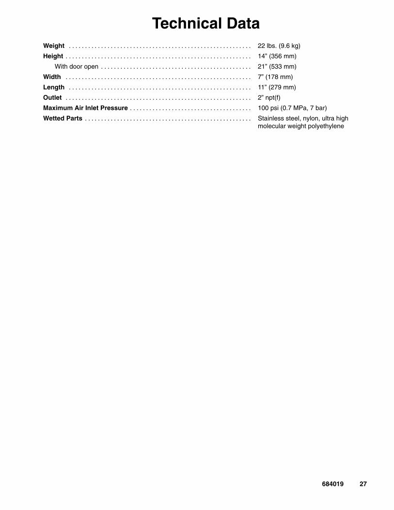
Technical DataWeight . . . . . . . . . . . . . . . . . . . . . . . . . . . . . . . . . . . . . . . . . . . . . . . . . . . . . . . . . 22 lbs. (9.6 kg)
Height . . . . . . . . . . . . . . . . . . . . . . . . . . . . . . . . . . . . . . . . . . . . . . . . . . . . . . . . . . 14” (356 mm)
With door open . . . . . . . . . . . . . . . . . . . . . . . . . . . . . . . . . . . . . . . . . . . . . . . 21” (533 mm)
Width . . . . . . . . . . . . . . . . . . . . . . . . . . . . . . . . . . . . . . . . . . . . . . . . . . . . . . . . . . 7” (178 mm)
Length . . . . . . . . . . . . . . . . . . . . . . . . . . . . . . . . . . . . . . . . . . . . . . . . . . . . . . . . . 11” (279 mm)
Outlet . . . . . . . . . . . . . . . . . . . . . . . . . . . . . . . . . . . . . . . . . . . . . . . . . . . . . . . . . . 2” npt(f)
Maximum Air Inlet Pressure . . . . . . . . . . . . . . . . . . . . . . . . . . . . . . . . . . . . . . 100 psi (0.7 MPa, 7 bar)
Wetted Parts . . . . . . . . . . . . . . . . . . . . . . . . . . . . . . . . . . . . . . . . . . . . . . . . . . . . Stainless steel, nylon, ultra highmolecular weight polyethylene

28 684019
Graco Standard WarrantyGraco warrants all equipment manufactured by Graco and bearing its name to be free from defects in material and workmanship onthe date of sale by an authorized Graco distributor to the original purchaser for use. With the exception of any special, extended, orlimited warranty published by Graco, Graco will, for a period of twelve months from the date of sale, repair or replace any part of theequipment determined by Graco to be defective. This warranty applies only when the equipment is installed, operated and maintainedin accordance with Graco’s written recommendations.
This warranty does not cover, and Graco shall not be liable for general wear and tear, or any malfunction, damage or wear caused byfaulty installation, misapplication, abrasion, corrosion, inadequate or improper maintenance, negligence, accident, tampering, or sub-stitution of non–Graco component parts. Nor shall Graco be liable for malfunction, damage or wear caused by the incompatibility ofGraco equipment with structures, accessories, equipment or materials not supplied by Graco, or the improper design, manufacture,installation, operation or maintenance of structures, accessories, equipment or materials not supplied by Graco.
This warranty is conditioned upon the prepaid return of the equipment claimed to be defective to an authorized Graco distributor forverification of the claimed defect. If the claimed defect is verified, Graco will repair or replace free of charge any defective parts. Theequipment will be returned to the original purchaser transportation prepaid. If inspection of the equipment does not disclose any defectin material or workmanship, repairs will be made at a reasonable charge, which charges may include the costs of parts, labor, andtransportation.
THIS WARRANTY IS EXCLUSIVE, AND IS IN LIEU OF ANY OTHER WARRANTIES, EXPRESS OR IMPLIED, INCLUDING BUTNOT LIMITED TO WARRANTY OF MERCHANTABILITY OR WARRANTY OF FITNESS FOR A PARTICULAR PURPOSE.
Graco’s sole obligation and buyer’s sole remedy for any breach of warranty shall be as set forth above. The buyer agrees that no otherremedy (including, but not limited to, incidental or consequential damages for lost profits, lost sales, injury to person or property, or anyother incidental or consequential loss) shall be available. Any action for breach of warranty must be brought within two (2) years of thedate of sale.
Graco makes no warranty, and disclaims all implied warranties of merchantability and fitness for a particular purpose in connectionwith accessories, equipment, materials or components sold but not manufactured by Graco. These items sold, but not manufacturedby Graco (such as electric motors, switches, hose, etc.), are subject to the warranty, if any, of their manufacturer. Graco will providepurchaser with reasonable assistance in making any claim for breach of these warranties.
In no event will Graco be liable for indirect, incidental, special or consequential damages resulting from Graco supplying equipmenthereunder, or the furnishing, performance, or use of any products or other goods sold hereto, whether due to a breach of contract,breach of warranty, the negligence of Graco, or otherwise.
FOR GRACO CANADA CUSTOMERSThe parties acknowledge that they have required that the present document, as well as all documents, notices and legal proceedingsentered into, given or instituted pursuant hereto or relating directly or indirectly hereto, be drawn up in English. Les parties reconnais-sent avoir convenu que la rédaction du présente document sera en Anglais, ainsi que tous documents, avis et procédures judiciairesexécutés, donnés ou intentés à la suite de ou en rapport, directement ou indirectement, avec les procedures concernées.
Graco InformationTO PLACE AN ORDER, contact your Graco distributor, or call one of the following numbers
to identify the distributor closest to you: 1–800–367–4023 Toll Free
612–623–6921612–378–3505 Fax
All written and visual data contained in this document reflects the latest product information available at the time of publication.Graco reserves the right to make changes at any time without notice.
Sales Offices: Minneapolis, DetroitInternational Offices: Belgium, Korea, Hong Kong, Japan
GRACO INC. P.O. BOX 1441 MINNEAPOLIS, MN 55440–1441www.graco.com
PRINTED IN USA 684019 10/1998, Revised 02/2002