gunner tracking models for the ml al combat vehicle ... · gunner tracking models for the ml al...
TRANSCRIPT
Gunner Tracking Models for the Ml Al Combat Vehicle
Engineering Simulation
Patrick E. Corcoran
.” I ,_,“, _
ARL-TR-1984 MAY 1999
Approved for public release; distribution is unlimited.

,
MATRIXx@ is a registered trademark of Integrated Systems, Inc.
XmathTM is a trademark of Integrated Systems, Inc.
The findings in this report are not to be construed as an offkial Department of the Army position unless so designated by other authorized documents.
Citation of manufacturer’s or trade names does not constitute an official endorsement or approval of the use thereof.
Destroy this report when it is no longer needed. Do not return it to the originator.
Abstract
During fiscal years 1998 and 1999, an effort was conducted as part of a technology program annex with the U.S. Army Test and Evaluation Command to develop gunner tracking models for the U.S. Army Research Laboratory’s Combat Vehicle Engineering Simulation (CVES). CVES contains engineering models of the fire control system, chassis-suspension, and the gunner for the Ml Al combat tank and the A3 version of the Bradley fighting vehicle system. This effort addresses the gunner model for the MlAl.
Gunner models were developed using the XmathTM interactive system identification algorithms from the MATRIXx@ software package along with measured gunner tracking error and estimated target rate data (gunner handle control output).
The resulting gunner tracking models are shown to be more accurate than the existing gunner tracking models used in CVES for two of the three maneuvering target paths that were considered in this study. Furthermore, the results demonstrate that usable models can be developed using the techniques discussed in this report.
ii

TABLEOFCONTENTS
1.
2. PROCEDURES . . . . . . . . . . . . . . . . . . . . . . . . . . . . . . . . . . . . . . . . . . . . . 2
3. RESULTS................................................. 10
3.1 Gunner Model Selection ....................................... 10 3.2 Lag and Lead Frequencies and Gain Selection ......................... 14 3.3 Comparison of Gunner Tracking Models ............................ 18
4. DISCUSSION . . . . . . . . . . . . . . . . . . . . . . . . . . . . . . . . . . . . . . . . . . . . . . 20
5. SUMMARY . . . . . . . . . . . . . . . . . . . . . . . . . . . . . . . . . . . . . . . . . . . . . . . 27
LIST OF FIGURES .......................................... v
LIST OF TABLES ........................................... vii
INTRODUCTION. .......................................... 1
REFERENCES.............................................. 29
DISTRIBUTION LIST . . . . . . . . . . . . . . . . . . . . . . . . . . . . . . . . . . . . . . . . 3 1
REPORT DOCUMENTATION PAGE . . . . . . . . . . . . . . . . . . . . . . . . . . . . 35
*.. 111

INTENTIONALLY LEFT BLANK
iv

LIST OF FIGURES
Figure Pag;e .
1.
. 2.
3.
4.
5.
6.
7.
8.
9.
10.
11.
ATMT Target-Lateral Motion .................................. 3
BRL Target-Lateral Motion .................................... 4
BRL Target-Vertical Motion ................................... 4
Gunner Input and Output-ATMT Lateral Target Path. ................. 6
Gunner Input and Output-BRL Lateral Target Path .................... 7
Gunner Input and Output-BRL Vertical Target Path ................... 8
Frequency Responses of the Azimuth Gunner Models ................... 21
Frequency Responses of the Elevation Gunner Models .................. 23
Comparison of ATMT Azimuth Gunner Model Output With Measured Data. .. 24
Comparison of BRL Azimuth Gunner Model Output With Measured Data. .... 25
Comparison of BRL Elevation Gunner Model Output With Measured Data .... 26
V

.
INTENTIONALLY LEFT BLANK
c
vi

LIST OF TABLES
Table Pag;e
1. Error Norms for Models Identified Using the Least Squares Algorithm-ATMT Lateral Target Path . . . . . . . . . . . . . . . . . . . . . . . . . . . . . . . . . . . . . . . . . . . 11
2. Error Norms for Models Identified Using the Subspace Identification Algorithm- ATMT Lateral Target Path . . . . . . . . . . . . . . . . . . . . . . . . . . . . . . . . . . . . . 11
3. Error Norms for Models Identified Using the Least Squares Algorithm-BRL Lateral Target Path. . . . . . . . . . . . . . . . . . . . . . . . . . . . . . . . . . . . . . 12
4. Error Norms for Models Identified Using the Subspace Identification Algorithm- BRL Lateral Target Path . . . . . . . . . . . . . . . . . . . . . . . . . . . . . . . . . . . . . . . 12
5. Error Norms for Models Identified Using the Least Squares Algorithm-BRL Vertical Target Path . . . . . . . . . . . . . . . . . . . . . . . . . . . . . . . . . . . . . . . . . . 13
6. Error Norms for Models Identified Using the Subspace Identification Algorithm- BRL Vertical Target Path. . . . . . . . . . . . . . . . . . . . . . . . . . . . . . . . . . . . . . . 14
7. Gunner Model Parameters-ATMT Lateral Target Path . . . . . . . . . . . . . . . . . 15
8. Gunner Model Parameters-BRL Lateral Target Path . . . . . . . . . . . . . . . . . . . 15
9. Gunner Model Parameters-BRL Vertical Target Path . . . . . . . . . . . . . . . . . . . 16
10. Gunner Model Gain Functions . . . . . . . . . . . . . . . . . . . . . . . . . . . . . . . . . . . 17
11. Error Norms of the SDS and CVES Models-ATMT Lateral Target Path . . . . . . 18
12. Error Norms of the SDS and CVES Models-BRL Lateral Target Path . . . . . . . . 19
13. Error Norms of the SDS and CVES Models-BRL Vertical Target Path . . . . . . . 19
vii

INTENTIONALLY LEFT BLANK
.
. . . Vlll

GUNNER TRACKING MODELS FOR THE MlAl COMBAT VEHICLE ENGINEERING SIMULATION
1. INTRODUCTION
For fiscal years 1998 and 1999, the Weapons Analysis Branch (WAB), Ballistics and
Weapons Concepts Division, Weapons and Materials Research Directorate (WMRD), of the
U.S. Army Research Laboratory (ARL) continued by way of a technology program annex (TPA)
with the U.S. Army Test and Evaluation Command (TECOM) to perform basic research and
exploratory development in support of its virtual proving ground (VPG). When completed, the
VPG will serve as a cohesive and comprehensive testing tool that leverages TECOM’s current
capabilities while adding modem modeling and simulation to provide better and faster test
support at lower cost.
One of the major efforts undertaken for fiscal years 1998 and 1999 was to develop gunner
tracking models for the WAB-developed Combat Vehicle Engineering Simulation (CVES). CVES
contains detailed engineering models of the fire control system, chassis-suspension, and the
gunner for both the Abrams Ml Al combat tank and the A3 version of the Bradley fighting
vehicle system (BFVS-A3). Input to CVES are target path and the terrain over which the Ml Al
and BFVS-A3 travel. CVES was built to determine the performance of the vehicles and their
weapon systems.
The motivation for developing new gunner models for CVES was twofold. During the 1996
fiscal year, also as part of the TPA with TECOM, the output of the MlAl portion of the CVES
were compared to actual data. The results of this comparison showed that the simulation did a
very good job of duplicating the lead angles but only a fair job of duplicating the tracking errors
(Corcoran & Perkins 1997). Thus, there was a need to develop better gunner tracking models for
CVES. Secondly, this effort demonstrated that usable models could be developed using measured
data. This will enhance ARL’s ability to develop human driver models that will be required for
the future Ground Vehicle Mobility Model.
It was unnecessary to conduct a test to collect the data to develop the gunner tracking models
since data from a test conducted by the Aberdeen Test Center (ATC) in the 1992-93 time frame
were already available. The purpose of this previous test had been to determine the feasibility of
incorporating an autotracker into the Ml Al. Manual tracking as well as autotracking was
considered in the test, but only the data from the manual tracking trials were considered in the

gunner model development. Data from this same test had been used in the 1996 comparison of the
Ml Al CVES results with actual data.
The gunner’s input is tracking error and the gunner’s output is handle control position. The
gunner moves the handle control in such a way as to keep the sight reticle on the target, thereby
minimizing the tracking error. In the Ml Al, the output of the handle control is a signal that is an
estimate of the target’s angular rate. Since the handle control position was not measured directly
during the test, the output signal from the handle control, which was measured, was used as a
measure of the gunner’s output. This is a reasonable substitute for the handle control position
since its output is from a transducer that converts handle control position to a voltage
proportional to estimated target rate. Thus, the signals of interest from the test for this study
were gunner tracking error and the estimated target rate.
Gunner tracking models were developed using the XmathTM interactive system identification
algorithms from the MATIUXx@ software package along with the measured gunner tracking error
and estimated target rate data. These models were compared to the existing CVES gunner models
to determine if they were more accurate.
The purpose of this report is to describe the development of the gunner tracking models for
the Ml Al. Similar models will be developed for the BFVS-A3 when the required test data are
available.
2. PROCEDURES
As mentioned, the measured input and output gunner data were obtained from a test
conducted in the 1992-93 time frame to determine the feasibility of installing an autotracker in the
Ml Al. This testing was conducted in ATC’s moving target simulator (MTS). The MTS is an
air-supported hemispherical structure that is 60 meters in diameter. The system undergoing test
is positioned inside the MTS and instrumented appropriately. A laser spot projected onto the
wall of the MTS represents the target. Target motion at a given range is simulated by driving the
laser spot with a computer-generated signal that is proportional to the target’s angular
displacement referenced to the system being tested. The gunner tracks the spot as though it were
a target; the simulated range to the target is manually input by the gunner to the ballistic
computer (since the laser range finder cannot be used to measure range in the test setup), and the
tank’s fire control system aims the gun. Time histories of various engineering quantities are
recorded at numerous test points for each trial. A big advantage of conducting tests in the MTS
is the repeatability of target motion.
2

Testing was conducted against two evasive targets: the ground vehicle antitank missile test
(ATMT) target and the aerial Ballistics Research Laboratory (BRL) target. The BRL target
represents an evasively maneuvering helicopter that delivers antitank guided missiles (ATGMs),
and the ATMT target represents an evasive tank maneuvering randomly. The ATMT target was
chosen because a portion of the materiel need effectiveness specifications for the Ml and the
M 1 A 1 is based on this target. An evasive helicopter target was chosen because such a target is
specified in the required operational capability document for the M830Al round for the Ml Al.
The ATMT target represents the actual motion of a tactical vehicle measured during field tests,
while the BRL target is an analytical target.
The lateral motion of the ATMT and BRL targets is shown in Figures 1 and 2,
respectively. A power spectral density (PSD) analysis of the ATMT lateral path showed that
most of the target motion occurs at frequencies below 0.31 rad/s (0.05 Hz). The BRL lateral path
motion is occurring at an average velocity of 10 m/s with the target accelerating and decelerating
about this point in a sine wave fashion at a frequency of 0.3 1 radk
120
100
-20
-40 I I I I I I I 1 I I 25 50 75 100 125 150 175 200 225 250
TIME (SEC)
Figure 1. ATMT Target-Lateral Motion.
3

0 10 20 35 40
TIME {SEC)
Figure 2. BRL Target-Lateral Motion.
The BRL target also has a vertical motion component (shown in Figure 3). The ATMT
target does not have a vertical component since it describes a ground target. These two targets
yielded the three target paths that were considered in this study.
115-
a5 I I I I
0 IO 20 30 40
TIME (SEC)
Figure 3. BRL Target-Vertical Motion.
4

These targets were maneuvering at simulated ranges of 1,2,3, and 4 kilometers. When
engaging the ATMT target, the gunners simulated firing kinetic energy (KE) rounds as far as 4
kilometers and high explosive antitank (HEAT) rounds as far as 3 kilometers. When engaging the
BRL target, the gunners simulated firing KE and training (TRNG) rounds as far as 4 kilometers.
The training round served as a surrogate for the M830Al round since the flight times of these
two rounds are similar.
Typically, 15 to 20 manual tracking trials were conducted for each test condition. To
obtain representative gunner input and output for each of the conditions tested, tracking errors
from similar trials were averaged together as a function of time, as were the estimated target rate
signals. These average time histories were then used as the input to the MATRIXx@ XmathTM
interactive system identification algorithms, and a gunner tracking model was developed for each
of the test conditions. Since the ATMT path had no vertical motion, the elevation tracking errors
and handle control output signals for this case were mostly noise. Therefore, no models were
developed for the gunner tracking the ATMT path in elevation. Typical averaged time histories
of the gunner input and output when tracking each of the target paths are shown in Figures 4
through 6, respectively.
The first step in the model development process was to remove the mean from the tracking
error and estimated target rate signals. The resulting time histories were then split so that the
first half of the time history data was used to identify the model and the second half was used for
model validation. The next step was to select an identification algorithm. There are a number of
MATRIXx@ algorithms to choose from, but only two of them produced stable models for just
about all the test conditions considered. These two algorithms are called least squares (LS) and
subspace identification (SDS). As the name implies, the least squares algorithm uses least
squares techniques to identify models, whereas the subspace identification algorithm uses
Kalman filter techniques to identify models. For details about these identification algorithms, the
reader is referred to the MATRIXx@ manuals (Integrated Systems, 1996).
The output of each of these identification algorithms is a series of single input, single
output linear time-invariant models. The output of the LS algorithm produced models of order
one through ten, and the SDS algorithm produced models of order one through three. Thus, for
each test condition, 13 gunner models were identified, making a total of 299 models (3 target
paths x [3 or 41 ranges x 2 rounds x 13 models per test condition)-obviously an unrealistic
number of models to use in CVES.
5

2
1.5
1
0.5
0
-0.5
-1
-1.5 0 50 100 150 200 250
Figure 4. Gunner Inmt and Outmt-ATMT Lateral Target Path (target range = 2.0 km, ICE round).
6
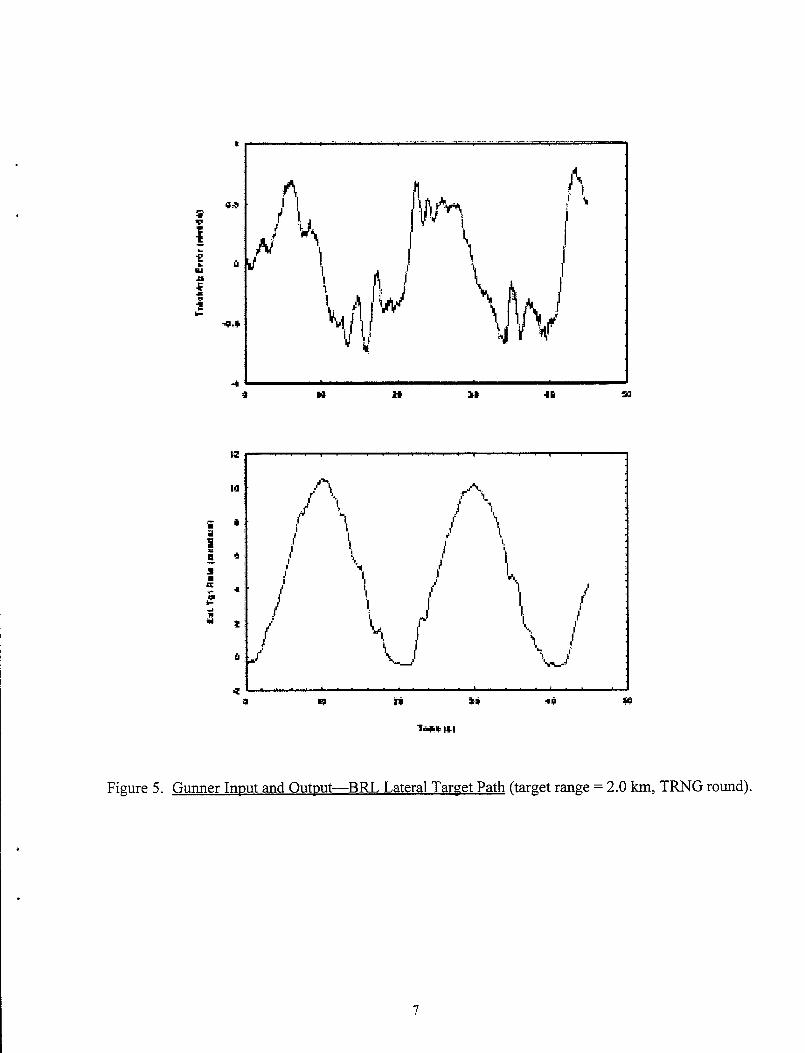
Figure 5. Gunner Inmt and Outmt-BRL Lateral Target Path (target range = 2.0 km, TFWG round).
7

40
0 10 20 30 40 -. 36
7rme (S)
Figure 6. Gunner Innut and Outnut-BRL Vertical Target Path (target range = 2.0 km, TRNG round).
Ideally, it would be advantageous from a CVES ease-of-modeling-and-use standpoint to
have one gunner model for all test conditions. However, it was obvious from the beginning of
this study that three fundamental gunner models were being identified-one for each target path
8

tracked. Thus, it was decided that one gunner model would be installed in CVES for each target
path tracked, provided that these new models were more accurate than the existing CVES gunner
models. The problem then became how to select the appropriate gunner models from all the
models identified.
To solve this problem, the accuracy of each identified model was computed by employing
the so-called error norm. The error norm provides a measure of how well the model output
agrees with the actual measured output. It is defined in the MATRIXx@ literature as the
standard deviation of the model error divided by the standard deviation of the actual measured
gunner output. The model error is the difference between the model output and the actual gunner
output. Therefore, a model with a lower error norm would be a more accurate model. For each
target path, the error norms for those models identified using the same identification algorithm
and of the same order were averaged together. The model order was then selected for each
combination of target path and identification algorithm by considering the average error norms or
accuracies.
A review of the average error norms for each identification algorithm and for each target
path showed that the LS first order models were nearly as accurate or more accurate than the
higher order LS models and the SDS first order models were always more accurate than the higher
order SDS models. This indicated that a first order model rather than a higher order model could
be used to represent the gunner. The question then became which first order model (the LS or
SDS model) to use. For each of the BRL target paths, the first order models identified by the LS
and SDS algorithms had almost the same average accuracy. However, for the ATMT lateral path,
the first order models identified by the SDS algorithm were slightly more accurate than the first
order models identified by the LS algorithm. Therefore, it was decided that the first order gunner
models identified by the SDS algorithms would serve as the fundamental gunner models for the
MlAl CVES.
The coefficients of the SDS first order models now had to be determined. In the frequency
domain, this meant that the lag frequency, lead frequency, and the gain of each model or transfer
function had to be determined. The averaging process was again used to determine these
coefficients for the three fundamental transfer functions. For a given target path, the average of
the SDS first order model lag frequencies was computed, as was the average of the lead
frequencies. These average frequencies became the lag,and lead frequencies of the first order SDS
model associated with a given target path.
9

In addition to determining the lag and lead frequencies of the transfer function, it was also
necessary to determine the steady state gain of the transfer function. The steady state gain of the
transfer function is the ratio between the estimated target rate and the tracking error at zero
frequency. As it occurred, this gain tended to decrease as the range to the target increased. For a
given target path, the gains of the first order SDS models at a given range were averaged, and a
second order polynomial was fitted to these averaged gains to estimate the steady state gain of
the gunner model as a function of range.
The form of the resulting gunner model when each target path was tracked was therefore a
first order model with a gain that varied as a function of range to the target.
The accuracy of these newly developed gunner models was compared to the accuracy of the
existing gunner models that are used in CVES. There would be no reason to use the new models
in CVES unless they were more accurate than the existing models. The present CVES has one
gunner model for the azimuth axis and one gunner model for the elevation axis, and these same
models are used regardless of the Ml Al-target scenario. The accuracies of the CVES models
were computed just as the accuracies of the newly developed SDS first order models were. The
models with the smaller error norms were considered to be the more accurate models.
3. RESULTS
3.1. Gunner Model Selection
The error norms or accuracies for each of the gunner models that were identified using the
LS algorithm and the SDS algorithm when the ATMT lateral target path was tracked, are shown
in Tables 1 and 2, respectively.
From Table 1, it is seen that on the average, the error norms for those gunner models that
were identified from the ATMT lateral target path tracking data and using the LS algorithm are
decreasing as the model order is increasing from the first through tenth order. This means that the
output from the higher order models is showing somewhat better agreement with measured data.
On the other hand, it is seen from Table 2 that the error norms for those models that were
identified using the SDS algorithm are increasing as the model order is increasing from the first
through third order. This implies that the output from the higher order SDS models is showing
poorer agreement with measured data. However, it is seen from the average error norms that the
first order SDS model is almost as accurate as the higher order LS models.
10

I *
Table 1. Error Norms for Models Identified Using the Least Squares Algorithm-ATMT Lateral Target Path
RANGE LEAST SQUARES MODEL ORDER
(W ROUND I 2 3 4 ‘5 6 7 8 9 10
1.0 ICEI 50 45 44 43 42 41 42 41 41 43
2.0 KE 51 50 49 48 47 46 45 44 43 42
3.0 KE 59 56 55 55 54 54 53 50 50 49
4.0 KE 48 46 46 46 45 44 44 42 41 40
1.0 -T 38 33 29 28 27 26 26 26 26 26
2.0 -T 45 40 39 36 33 32 30 30 29 28
3.0 -T 37 33 33 32 32 32 31 31 31 32
AVJZ~GEs 47 43 42 41 40 39 39 38 37 37
(Table entries are in percent.)
Table 2. Error Norms for Models Identified Using the Subspace Identification Algorithm-ATMT Lateral Target Path
I SUBSPACE IDENTIFICATION RANGE MODEL ORDER (W ROUND 1 2 3
1.0 KEI 47 64 64 -_-
2.0 KE 48 57 57
3.0 KE 55 64 65
4.0 KE 46 57 75
1.0 IEAT 31 41 42
2.0 -T 37 50 55
1 A 1 HEAT 1 30 1 36 1 38 11
AVERAGES I 42 I 53 57
,Table entries are in percent.)
The error norms or accuracies for each of the gunner models that were identified using the
LS algorithm and the SDS algorithm when the BRL lateral target path was tracked, are shown in
Tables 3 and 4, respectively.
In Table 3, it is seen that on the average, the error norms for those gunner models that were
identified from the BRL lateral target path tracking data and using the LS algorithm are about the
11

same for all model orders. This means that the output from the lower order LS models is just
about as accurate as the output from the higher order LS models. The sixth through tenth order
LS models identified for the 3.0~km case when the KE round was “fired” were the only ones in
this entire study that were found to be unstable.
Table 3. Error Norms for Models Identified Using the Least Squares Algorithm-BRL Lateral Target Path
RANGE LEAST SQUARES MODEL ORDER
(km) ROUND 1 1 2 1 3 1 4 1 5 1 6 1 7 1 8 ( 9 1 IO
II AVERAGES 23 1 23 1 23 1 22 1 25 1 26 1 31 1 29 1 25 11 (Table entries are in percent.)
Table 4. Error Norms for Models Identified Using the Subspace Identification Algorithm-BFX Lateral Target Path
SUBSPACE IDENTIFICATION MODEL ORDER
(W 1 ROUND 1 1 2 I 3 II
1.0 KE 31 25 27 2.0 m 17 33 46 I -__
I
3.0 I KE I 26 I 46 ! 41 II 4.i D I KE I 28 ! 30 ! 35 II 1.0 TRNG 20 29 65 2.0 TRNG 19 20 22 3.0 TRNG 41 21 28 4.0 TRNG 31 33 31
I -.- I 1 I
AVERAGES I 27 30 I 37 (Table entries are in percent.)
12

.
From Table 4, it is seen that the, error norms for those models that were identified using the
SDS algorithm are increasing as the model order is increasing from the first through third order.
Once more, the output from the higher order SDS models is showing poorer agreement with
measured data. It is also seen from the average error norms that the first order SDS model is just
about as accurate as all the LS models.
The error norms for each of the gunner models that were identified using the LS algorithm
and the SDS algorithm when the BRL vertical target path was tracked, are shown in Tables 5 and
6, respectively.
Table 5. Error Norms for Models Identified Using the Least Squares Algorithm-BRL Vertical Target Path
(Table entries are in percent.)
In Tables 5 and 6, the same trends are seen in the average error norms that were seen
previously. For those models identified using the BRL vertical target path tracking data and the
LS algorithm, the error norms are about the same for all model orders, and for those models
identified using the SDS algorithm, the error norms are increasing as the model order is increasing.
Also, it is again seen from the average error norms that the first order SDS model is as accurate as
all the LS-developed models.
The results in these tables show that the first order models are nearly as accurate or more
accurate than the higher order models. For the two BRL paths, the LS and SDS first order
models exhibit nearly the same accuracy. However, for the ATMT lateral path, the first order
13
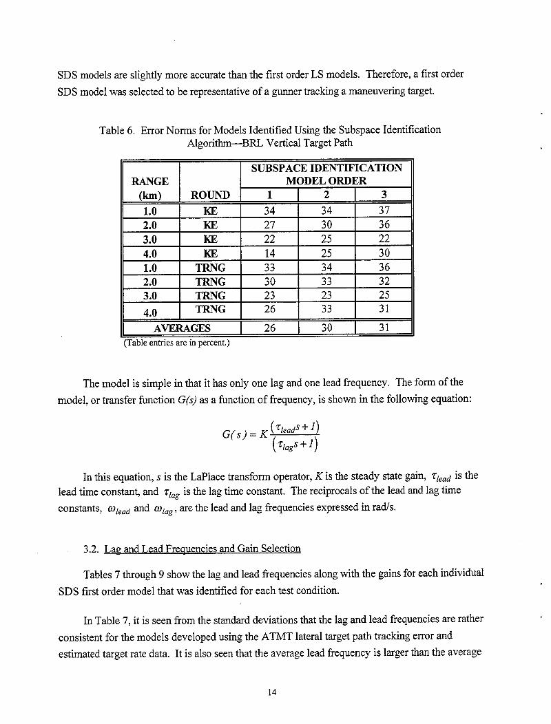
SDS models are slightly more accurate than the first order LS models. Therefore, a first order
SDS model was selected to be representative of a gunner tracking a maneuvering target.
Table 6. Error Norms for Models Identified Using the Subspace Identification Algorithm-BFU Vertical Target Path
lr-~ I 1 SUBSPACE IDENTIFICATION RANGE MODEL ORDER
(W ROUND 1 2 3
1.0 m 34 34 37 2.0 KE 27 30 36 3.0 KE 22 25 22 4.0 KE 14 25 30 1.0 TRNG 2.0 TRNG 3.0 TRNG 4.0 TRNG
AVERAGES (Table entries are in percent.)
33 34 36 30 33 32 23 23 25 26 33 31
26 30 31
The model is simple in that it has only one lag and one lead frequency. The form of the
model, or transfer function G(s) as a function of frequency, is shown in the following equation:
G(s) = K ( ZleadS + I) (%gs+g
In this equation, s is the LaPlace transform operator, K is the steady state gain, TIead is the lead time constant, and zlag is the lag time constant. The reciprocals of the lead and lag time
COIlStZU’ltS, @lead and Wlag, are the lead and lag frequencies expressed in rad/s.
3.2. Lap and Lead Freauencies and Gain Selection
Tables 7 through 9 show the lag and lead frequencies along with the gains for each individual
SDS first order model that was identified for each test condition.
In Table 7, it is seen from the standard deviations that the lag and lead frequencies are rather
consistent for the models developed using the ATMT lateral target path tracking error and
estimated target rate data. It is also seen that the average lead frequency is larger than the average
14

.
lag frequency. A PSD analysis of the tracking error shown in Figure 4 indicated that most of the
tracking error occurs at frequencies below 1.25 rad/s. The lead term will not have much of an
effect on the input amplitude, but it will affect the phase shift between the input and output,
especially for those input frequencies that are greater than 0.30 rads. It is also seen in Table 7
that the steady state gains are decreasing as the target range is increasing.
Table 7. Gunner Model Parameters-ATMT Lateral Target Path
RANGE SDS MODEL PARAMETERS
(W ROUND Wlag %wd K
1.0 Klz 0.60 2.87 7.22
2.0 KE 0.49 3.40 6.00
3.0 KE 0.41 3.80 5.46
4.0 KE 0.54 4.17 3.50
1.0 HEAT 0.39 2.53 9.05
2.0 HEAT 0.37 2.17 5.80
3.0 HEAT 0.34 1.68 3.69
AVERAGES 0.45 2.95 NA
STANDARD DEVIATION 0.10 0.90 NA
Table 8. Gunner Model Parameters-BRL Lateral Target Path
RANGE
(km) 1.0
2.0
3.0
4.0
ROUND
ME
KE
KE
KE
MODEL PARAMETERS
Wag %xd K
0.073 -25.19 62.07
0.058 27.10 60.32
0.032 7.17 81.82
0.054 3.09 38.99
1.0 I TRNG I 0.070 1 16.36 1 50.56 2.0 I TRNG I 0.037 I 9.22 I 82.91
3.0 I TRNG I 0.052 I 4.73 I 47.90
4.0 TRNG 0.113 3.18 12.63
AVERAGES 0.061 10.12 NA
STANDARD DEVIATION 0.025 8.79 NA
1.5

Table 9. Gunner Model Parameters-BRL Vertical Target Path
II RANGE MODEL PARAMETERS
0-J ROUND %lg ‘%zad K
1.0 KEI 0.48 3.77 15.87
2.0 KE 0.69 11.21 9.32 3.0 m 0.77 12.32 8.19
4.0 KE 0.92 687.96 5.28 1.0 TRNG 0.45 3.48 11.83
2.0 TRNG 1.12 13.22 7.17
3.0 TRNG 0.93 11.28 4.38
4.0 TRNG 0.77 2.18 2.95
AVERAGES 0.77 8.21 NA
STANDARD DEVIATION 0.23 4.81 NA
Referring to Table 8, it is seen that the lag frequencies are again rather consistent, but the
lead frequencies are more variable. Furthermore, the lead frequency is negative when the 1 .O-km
BRL lateral target path is tracked and the KE round is “fired.” A system or model with this
characteristic is referred to as a “non-minimum phase system.” The gain of a non-minimum
phase system will not differ from that of a minimum phase system, but the phase shift between
the system’s input and output will differ. Therefore, this lead frequency was considered as an
outlier and was not considered in the statistics.
A PSD analysis of the tracking error shown in Figure 5 indicated that the tracking error
occurs predominantly at a frequency of 0.3 1 rad/s, but there are higher frequencies, as great as
about 1.50 rad/s, present in the signal. The average lead frequency is much higher than 1.50 rad/s
and therefore will not have much of an effect on either the input amplitude or phase shift
between the input and output.
The trend of the steady state gains for these models is not as clearly defined as it was for
the previous models.
In Table 9, the lag frequencies are again rather consistent and the lead frequencies are more
variable. The lead frequency for the model identified with tracking the BRL vertical target path at
16

I 0
4 kilometers and “firing” the KE round is shown to have a lead frequency of 687.96 radh
(obviously an outlier) and was not considered in the statistics.
Like the other models, the lead frequency for this model is considerably higher than the lag
frequency. A PSD analysis of the tracking error shown in Figure 6 also indicated that the
tracking error occurs predominantly at a frequency of 0.3 1 rad/s, with higher frequencies as great
as about 1 SO rad/s present in the signal. The lead term will have no effect on the input amplitude
but it will have an effect on the phase shift between the input and output, especially when the
input signal frequency is greater than 0.82 rad/s.
The steady state gains associated with the models identified when the BRL vertical target
path is tracked are seen to be decreasing as the range to the target is increasing.
Having determined the average lag and lead frequencies for the first order SDS models
associated with each of the target paths, we now determined the gain function for each model. It
is seen in Tables 7 and 9, and to some degree in Figure 8, that the gunner’s gain tends to decrease
as the range to the target increases. Therefore, a second order polynomial fit was applied to the
averages of the identified gains. The equations for the gain of each model and the root sum square
(RSS) of the differences between the average gain and the polynomial fit are shown in Table 10.
Table 10. Gunner Model Gain Functions
MODEL GAIN FUNCTION RSS
A~~TERAL K = 0.29R2-2.97R+10.79 0.15
BRLLATERAL K =-13.59R2+58.11R+11.28 2.29
BRLVERTICAL K = 0.86R2-7.41R+20.21 0.86
Consistent with the identified gains, it is seen from Table 10 that the fitted gains associated
with each of the target paths are different. Furthermore, referring to the RSS of the errors for
each of the models, the gain functions all show good agreement with the identified gains. These
gain functions are only good for target ranges of 1 to 4 kilometers.
The results presented in this section show that the gunner’s transfer function depends on
the target path that is tracked since the average lag and lead frequencies and the gain function
differ for each path tracked.
I 17

3.3. Comparison of Gunner Tracking; Models
The error norms or accuracies for the newly developed average SDS and existing CVES
azimuth gunner models when the ATMT lateral target path is tracked are shown in Table 11.
Table 11. Error Norms of the SDS and CVES Models-ATMT Lateral Target Path
(Table entries are in percent.)
In Table 11, it is seen that individually and on the average, the SDS model error norms are
considerably smaller than the CVES azimuth model error norms. This indicates that the SDS
gunner tracking model is considerably more accurate than the CVES azimuth gunner tracking
model when the ATMT lateral target path is tracked.
The error norms for the SDS and CVES azimuth gunner models when the BRL lateral target
path is tracked are shown in Table 12. These results indicate that the SDS gunner model is not as
accurate as the CVES azimuth gunner model when the BRL lateral path target is tracked. In most
of the cases, and on the average, the SDS model error norms are larger than the CVES azimuth
model error norms.
The error norms for the SDS and CVES models when the BRL vertical target path is tracked
are shown in Table 13.
18

Table 12. Error Norms of the SDS and CVES Models-BRL Lateral 1
(Table entries are in percent.)
Table 13. Error Norms of the SDS and CVES Models-BRL Vertical Ts lrget Path
RANGE MODEL
0-1 ROUND SDS CVES-EL
1.0 l-a 47 66
2.0 m 38 62
3.0 KE 38 67
4.0 KE 29 64
1.0 TRNG 55 58
II 2.0 1 TRNG 1 32 1 48 11
(Table entries are in percent.)
:get Path
The error norm results presented in Table 13 show that the SDS model is more accurate
than the CVES elevation model for all but one of the test conditions, and on the average, when the
BRL vertical target path is tracked.
19

In summary, the first order SDS gunner models are more accurate than the present CVES
models when the ATMT lateral target path and BRL vertical target path are tracked. The first
order SDS model is not as accurate as the CVES azimuth model when the BRL lateral target path
is tracked.
4. DISCUSSION
The results presented in Section 3 show that first order SDS models are adequate to
describe the gunner when each of the target paths considered in this study is tracked. However,
the coefficients of the first order models differ, depending on the target path tracked. The fact
that the model coefficients differ implies that the gunners are adapting their transfer function to
the target path being tracked. The differences in the SDS azimuth models can readily be seen in
Figure 7, which shows typical frequency responses (gain and phase responses) of the azimuth
models developed from gunner input and output data when the ATMT and BRL lateral target
paths are tracked. Also shown in Figure 7 is the frequency response of the existing CVES
azimuth model. These frequency responses are representative of the gunner tracking a target at
2.0 km.
Over the tracking error frequency range of interest for the ATMT path (0 to 1.25 rad/s), the
ATMT azimuth SDS model has a lower gain and less phase shift between the output and input
than the BRL azimuth model. The difference in the phase responses between the ATMT and
BRL azimuth models is consistent with the time histories of the gunner input and output for
these two paths shown in Figures 4 and 5. In Figure 4, it is seen that there is little phase shift
between the tracking error and the estimated target rate when the ATMT lateral target path is
tracked. From Figure 7, it is seen that the model’s phase shift is less than 50” over the frequency
range of interest for the ATMT lateral target path.
The BFZ lateral target path tracking errors are occurring predominantly at a frequency of
0.3 1 rad/s. In Figure 5, it appears that there is about 90” of phase shift between the tracking
error and estimated target rate at this frequency. From Figure 7, it is seen that the model’s phase
shift is about 80” at a frequency of 0.31 rad/s.
The gain of the ATMT azimuth SDS model is also consistent with the gunner input and
output shown in Figure 4. From Figure 4, it is seen that the gain at the lower frequencies when
the ATMT lateral target path is tracked is about 6 or 16 dB. From Figure 7, it is seen that the
ATMT azimuth SDS model gain is also about 16 dB at the lower frequencies.
20

50
40
30
z
E 20
4
10
0
-1 0
____-_------ ‘42 ATM7 AZ SDS
\ \
\ BRL AZ SDS
_----- CVES AZ
0
-50
-100
a
4
* -150
1
E
-200
-250
-300
O_ol 0 1 1 10
0.01 0.1 1 10
Freqlremy (t-ado's)
Figure 7. Freauencv Resnonses of the Azimuth Gunner Models (target range = 2.0 km).
The gain of the BRI; azimuth SDS model is not as consistent with the gunner input and
output as is the ATMT azimuth SDS model. From Figure 5, the gain between the input and
21

output is on the order of 11 or 21 dB. In Figure 7, the gain of the BFU azimuth SDS model at a
frequency of 0.3 1 rad/s is about 25 dB.
The frequency response of the model developed for the gunner when the BRL vertical
target path is tracked is shown in Figure 8. Also shown in Figure 8 is the frequency response of
the existing CVES elevation model. Both the gain and the phase of the BRL elevation SDS model
are consistent with the time histories of the gunner input and output shown in Figure 6. From
Figure 6, the gain at 0.31 rad/s is estimated to be about 7 or 17 dB, and there is little, if any,
phase shift. From Figure 8, it is seen that the gain of the BR_L elevation SDS model is about 18
dB and the phase shift is about 20” at a frequency of 0.3 1 rad/s.
The results also show that the SDS gunner models are more accurate than the existing CVES
gunner models when the ATMT lateral target path and BRL vertical target path are tracked but not
as accurate when the BRL lateral target path is tracked. A comparison of the ATMT and CVES
azimuth model output with actual measured data is shown in Figure 9. It is readily seen that the
output of the ATMT azimuth SDS model is in much closer agreement with the measured output.
A similar comparison is shown in Figure 10 for the BRL, azimuth models. It is seen that the
CVES azimuth model output agrees better with the measured data than the output of the BRL
azimuth SDS model does. The BRL azimuth SDS model output agrees in phase with the
measured data, but the model over-predicts the amplitude. This is consistent with the frequency
response plots shown in Figure 7, whereby the gain of the BRL SDS model is greater than the
gain of the CVES model. Except for the gain difference, the frequency responses of the BRL
azimuth SDS model and the CVES azimuth models are similar in the vicinity of the path
frequency. Over the frequency range of 0.1 to 1 .O rad/s, the gain of both models is decreasing at a
rate of about 20 dB/decade, and at the BRL path frequency of 0.3 1 rad/s, the phase shift of both
models is about the same. If the gain of the BRL azimuth SDS model were reduced by about 6
dB, the output of the two models would be close to being the same.
The comparison between the output of the BRL elevation SDS and CVES elevation models
is shown in Figure 11. In elevation, the output of the BRL elevation SDS model is in better
agreement with the actual data. Both models correctly predict the phase of the output, but the
CVES elevation model under-predicts the output amplitude. This again is consistent with the
frequency responses shown in Figure 8. The BRL elevation SDS model has about a 6-dB larger
gain than the CVES elevation model at a frequency of 0.3 1 rad/s. It is also seen in-Figure 8 (and
Table 9) that the bandwidth (frequency at which the gain is 3 dB less than the steady state gain)
.
22

of the BRL elevation SDS model is 0.77 radk ( olQg) whereas the bandwidth of the CVES
elevation model is 10 rad/s.
-120
-140 LLlr 0.1 1 10
Froqrracy (md:e)
Figure 8. Freauencv Responses of the Elevation Gunner Models (target range = 2.0 km).
23

MfAS DATA
-w---w ATM1 AZ SDS
._-...-...-...-...- CVES AZ
ii :I
li 19
ir : ; f f
Figure 9. Comnarison of ATMT Azimuth Gunner Model Outnut With Measured Data (target range = 2.0 km, KE round).
24

15
10
5
-5
-10
-15 0 10 20 30 00 50
Time(s)
Figure 10. Comnarison of BRL Azimuth Gunner Model Outnut With Measured Data (target range = 2.0 km, TRNG round).

5 I-
ii w
-1 -
0 10 20 30 10 50
‘Irma (5)
Figure 11. ComDarison of BRL Elevation Gunner Model Outtwt With Measured Data (target range = 2.0 km, TRNG round).
26

5. SUMMARY
The results presented in this report show that usable gunner tracking models can be
developed using measured data along with the interactive system identification algorithms from
the MATRIXx@ software package. Depending on the identification algorithm selected, models
as high as the tenth order were identified for each target path considered, but it was shown that
the first order models were about as accurate as the higher order models. A first order model was
developed for each of the three target paths that were considered in this study.
It was shown that for two of the three target paths tracked, the gunner models developed
using the techniques discussed in this report were more accurate than the existing gunner models
that are presently being used in CVES. This was especially true for the gunner model developed
when the random ATMT lateral target path was tracked. The newly developed model was about
six times more accurate than the CVES azimuth model in predicting the gunner output. The other
model that was more accurate than an existing CVES model was the gunner model developed for
tracking the BRL vertical path. It was 27% more accurate in predicting the gunner output.
On the other hand, the model developed for tracking the BRL lateral target path was shown
to be about 51% less accurate than the CVES azimuth model. This was the result of using the
averaging process in developing the model. If the output of each individual model, rather than the
output of the average model, were compared to the output of the CVES azimuth model, the
MATRIXx@-identified models would be as accurate as the CVES azimuth model when the BRL
lateral target path is tracked. As mentioned in Section 2, it is not practical to use a separate
model in CVES for each combination of range and round; there would be too many gunner models
from which to choose.
These newly developed models are simpler in their structure than the existing CVES
models. The new models are first order lag-lead networks with a gain that varies as a function of
range. The CVES azimuth gunner model consists of a time delay, a gain that varies as a function
of range, an integrator, a lag-lead network, and a quadratic filter. The CVES elevation gunner
consists of a time delay, a gain that varies as a function of range, and a first order low pass filter.
The Ml Al gunner models developed for tracking the ATMT ‘lateral target path and the
BRL vertical target path have been installed in CVES. However, they should only be used with
the Ml Al CVES. These gunner models were observed to depend on the target path, and they
may depend on the weapon system as well. The weapon system dependency will not be known
until gunner models are developed for the BFVS-A3. BFVS-A3 gunner models will be developed
.
21

for CVES using the techniques discussed in this report once the tracking error and estimated
target rate data become available for this weapon system.
The Ml Al CVES user should select the ATMT lateral target path gunner model if the
target path to be considered tends to be random and has a frequency content similar to that of the
ATMT lateral path. Likewise, the BRL vertical path gunner model should be selected if the
target vertical path to be considered tends to be like the BRL vertical path. If significantly
different target paths are to be considered, then additional gunner models should be developed.
The existing CVES gunner models have been retained in the simulation and should be used
with the BFVS-A3 CVES and the different target paths until the additional gunner models are
developed and installed in CVES.
Although a formal verification of the MlAl CVES with the new gunner models has not yet
been conducted, initial indications are that the CVES tracking error output is now in better
agreement with measured data.
As a result of this effort and the future effort to identify BFVS-A3 gunner models, a test
conductor running a test in the VPG and using CVES will have the capability to select a more
appropriate gunner model in addition to selecting the other available options. The other available
user options that have been built into CVES include the selection of target range, target path,
vehicle motion, ammunition, fire control configuration, and the type of turret and gun drives.
.
28
~ ’ I
.
6. REFERENCES
Corcoran, P. E., and T. R. Perkins, “A Comparison of ARL’s Ml Al Engineering Simulation results With Actual Test Results.” ARL-MR-347, U.S. Army Research Laboratory, Aberdeen Proving Ground, MD, March 1997.
Integrated Systems, Inc. (revised January 1996), Xmath Interactive System Identification Module, Part Number 000-0027-002, Santa Clara, CA: Author.
I .
I .
29

.
INTENTIONALLY LEFT BLANK
30

NO. OF ORGANIZATION COPIES
2 ADMINISTRATOR DEFENSE TECHNICAL INFO CENTER AT-IN DTIC OCP 8725 JOHN J KINGMAN RD STE 0944 FT BELVOIR VA 22060-62 18
1 DIRECTOR US ARMY RESEARCH LABORATORY ATT-N AMSRL CS AL TA REC MGMT 2800 POWDER MILL RD ADELPHI MD 20783- 1197
1 DIRECTOR US ARMY RESEARCH LABORATORY ATTN AMSRL CI LL TECH LIB 2800 POWDER MILL RD ADELPHI MD 207830- 1197
1 DIRECTOR US ARMY RESEARCH LABORATORY ATTN AMSRL DD J J ROCCHIO 2800 POWDER MILL RD ADELPHI MD 20783-l 197
1 PROJECT MANAGER TANK MAIN ARMAMENT SYSTEM ATTN SMCAR CCM PICATINNY ARSENAL NJ 07806-5000
3 COMMANDER US ARMY ARDEC ATTN SMCAR ASF
SMCAR AEF CD SMCARFSFBD
PICATINNY ARSENAL NJ 07806-5000
1 PROJECT MANAGER ABRAMS TANK SYSTEM ATTN SFAE ASM AB WARREN MI 48397-5000
4 COMMANDER US ARMY ARMOR SCHOOL ATTN ATSB CDM
ATSB TSM ATZK TS ATZK CID
FT KNOX KY 40121-5000
3 US ARMY TACOM AT-IN AMSTA TR D
AMSTA TR R AMSTA TR S
WARREN MI 48397-5000
NO. OF COPIES ORGANIZATION
1 DIRECTOR US ARMY REDSTONE TECH TEST CTR ATTN STERT TE C (CHARLES CROCKER) REDSTONE ARSENAL AL 35898-8052
1 COMMANDER US ARMY DUGWAY PROVING GROUND ATTN STEDP TD SP DUGWAY PROVING GROUND DUGWAY UT 84022
1 COMMANDER US ARMY ELECTRONIC PROVING GRD ATTN STEWS EPG TT FORT HUACHUCA AZ 85613-7110
1 US ARMY AVIATION TECH TEST CTR AT-I-N STEAT CO FORT RUCKER AL 36362-5276
1 COMMANDER WHITE SANDS MISSILE RANGE ATTN STEWS IDD R WHITE SANDS NM 88002
1 UNITED DEFENSE LP 328 BROKAW ROAD ATTN J GROFF MAIL DROP 10 SANTA CLARA CA 95050
1 UNITED DEFENSE LP 1450 COLEMAN AVE ATTN J WALSH MAIL DROP X70 SANTA CLARA CA 95050
1 DOD JOINT CHIEFS OF STAFF ATTN 539 CAPABILITIES DIV
CAPT J M BROWNELL THE PENTAGON RM 2C865 WASHINGTON DC 20301
1 OFC OF THE SECY OF DEFNS ATTN ODDRE (R&AT) G SINGLEY THE PENTAGON WASHINGTON DC 20301-3080
1 OSD ATTN OUSD(A&T)/ODDDR&E(R) ATTN RJTREW THE PENTAGON WASHINGTON DC 203 lo-0460
31

NO. OF COPIES
1
1
1
1
1
1
1
1
1
1
1
ORGANIZATION NO. OF COPIES
AMCOM MRDEC ATTN AMSMI RD W C MCCORKLE REDSTONE ARSENAL AL 35898-5240
CECOM ATTN PM GPS COL S YOUNG FT MONMOUTH NJ 07703
CECOM SP & TERRESTRIAL COMMCl-N DIV ATTN AMSEL RD ST MC M H SOICHER FT MONMOUTH NJ 07703-5203
US ARMY INFO SYS ENGRG CMND AT-IN ASQB OTD F JENIA FT HUACHUCA AZ 85613-5300
US ARMY NATICK RDEC ACTING TECHNICAL DIR ATTN SSCNC T P BRANDLER NATICK MA 01760-5002
US ARMY RESEARCH OFC 4300 S MIAMI BLVD RESEARCH TRIANGLE PARK NC 27709
US ARMY SIMULATION TRAIN & INSTRMNTN CMD
ATTN J STAHL 12350 RESEARCH PARKWAY ORLANDO FL 32826-3726
US ARMY TANK-AUTOMOTIVE & ARMAMENTS CMD
ATTN AMSTA AR TD M FISETTE BLDG 1 PICATINNY ARSENAL NJ 07806-5000
US ARMY TANK-AUTOMOTIVE CMD RD&E CTR ATTN AMSTA TA J CHAPIN WARREN MI 48397-5000
US ARMY TRAINING & DOCTRINE CMD BATTLE LAB INTEGRATION & TECH DIR ATTN ATCD B J A KLEVECZ FT MONROE VA 2365 l-5850
NAV SURFACE WARFARE CTR ATT-N CODE B07 J PENNELLA 17320 DAHLGREN RD BLDG 1470 RM 1101 DAHLGREN VA 22448-5 100
1
1
1
1
1
1
2
1
14
3
ORGANIZATION
DARPA ATTN B KASPAR 3701 N FAIRFAX DR ARLINGTON VA 22203-1714
UNIV OF TEXAS ARL ELECTROMAG GROUP CAMPUS MAIL CODE F0250 ATTN A TUCKER AUSTIN TX 78713-8029
HICKS & ASSOCIATES, INC. ATT-N G SMGLEY III 1710 GOODRICH DR STE 1300 MCLEAN VA 22 102
SPECIAL ASST TO THE WING CDR SOSW/CCX CAPT P H BERNSTEIN 300 O’MALLEY AVE STE 20 FALCON AFB CO 80912-3020
HQ AFWADNX 106 PEACEKEEPER DR STE 2N3 OFFUTT AFB NE 68113-4039
US ARMY EDGEWOOD RDEC AT-l-N SCBRD TD J VERVIER APG MD 21010-5423
ABERDEEN PROVING GROUND
DIRECTOR US ARMY RESEARCH ATT-N AMSRL CI LP BLDG 305 APG AA
DIR USARL AT-I-N AMSRL WM B BLDG 4600
DIR USARL
LABORATORY (TECH LIB)
A W HORST JR
ATTN AMSRL WM BF J LACETERA P CORCORAN (10 CYS) P FAZIO R PEARSON G SAUERBORN
BLDG 120
CDR USA TECOM AT-l-N AMSTE CD B SIMMONS
AMSTE CD M R COZBY J HAUG
RYAN BLDG
32

NO. OF ORGANIZATION COPIES
4 CDR USA ATC i ATTN STEAC CO COL ELLIS
STEAC TD J FASIG STEAC TE H CUNNINGHAM
. STEAC RM C A MOORE BLDG 400
2 CDR USA ATC ATTN STEAC TE F P OXENBERG
STEAC TE F A SCRAMLIN BLDG 321
ABSTRACT ONLY
1 DIRECTOR US ARMY RESEARCH LABORATORY ATTN AMSRL CS AL TP TECH PUB BR 2800 POWDER MILL RD ADELPHI MD 20783- 1197
33

INTENTIONALLY LEFT BLANK
34

REPORT DOCUMENTATION PAGE Form Approved OMB No. 0704-0188
Public reporting burden for this collection of infonation is estimated to average 1 hour per response, including the time for reviewing instructions, searching existing data sources. gathering and maintaining the data needed, and completing and reviewing the collection of information. Send comments re
9 arding this burden eshmate or any other aspect Of this
collection of information, including suggestions for reducing this burden, to Washington Headquarters Services, Directorate or Information Operations and Reports, 1215 Jefferson Davis Highway, Suite 1204, Arlington. VA 22202-4302, and to the Office of Management and Budget, Papenvork Reduction Project (0704-0188), Washington, DC 20503.
AGENCY USE ONLY (Leave blank) 2. REPORT DATE 3. REPORT TYPE AND DATES COVERED
May 1999 Final
1. TITLE AND SUBTITLE 5. FUNDING NUMBERS
Gunner Tracking Models for the MlAl Combat Vehicle Engineering Simulation PR: lL162618AHSO
i. AUTHOR(S)
Corcoran, P.E. (ARL)
‘_ PERFORMING ORGANIZATION NAME(S) AND ADDRESS
U.S. Army Research Laboratory
Weapons and Materials Research Directorate Aberdeen Proving Ground, MD 21010-5066
8. PERFORMING ORGANIZATION REPORT NUMBER
I. SPONSORING/MONITORING AGENCY NAME(S) AND ADDRESS
U.S. Army Research Laboratory Weapons and Materials Research Directorate Aberdeen Proving Ground, MD 2 10 lo-5066
1. SUPPLEMENTARY NOTES
10. SPONSORING/MONITORING AGENCY REPORT NUMBER
ARL-TR-1984
2a. DISTRIBUTION/AVAILABILITY STATEMENT
Approved for public release; distribution is unlimited.
12b. DISTRIBUTION CODE
13. ABSTRACT (Maximum 200 words)
During fiscal years 1998 and 1999, an effort was conducted as part of a technology program annex with the U.S. Army Test and Evaluation Command to develop gunner tracking models for the U.S. Army Research Laboratory’s Combat Vehicle Engineering Simulation (CVES). CVES contains engineering models of the fire control system, chassis-suspension, and the gunner for the Ml Al combat tank and the A3 version ofthe Bradley fighting vehicle system. This effort addresses the gunner model for the MlAl.
Gunner models were developed using the XmathTM interactive system identification algorithms from the MATRIXx@ software package along with measured gunner tracking error and estimated target rate data (gunner handle control output).
The resulting gunner tracking models are shown to be more accurate than the existing gunner tracking models used in CVES for two of the three maneuvering target paths that were considered in this study. Furthermore, the results demonstrate that usable
models can be developed using the techniques discussed in this report.
14. SUBJECT TERMS
engineering models gunner tracking error
17. SECURITY CLASSIFICATION OF REPORT
Unclassified
gunner tracking models maneuvering targets
18. SECURITY CLASSIFICATION OF THIS PAGE
Unclassified
19. SECURITY CLASSIFICATION OF ABSTRACT
Unclassified
15. NUMBER OF PAGES
40 16. PRICE CODE
20. LIMITATION OF ABSTRACT
Standard Form 298 IRev. 2-891 NSN 7540-01-280-5500 35 -.-. _-- -.. ~ ~~, Prescribed by ANSI Std. 239-18 298-l 02