gw instek gds-1152a -...
TRANSCRIPT

Written by branadic 2009-09-01 [email protected]
Review of the GW Instek GDS-1152A
I ordered a test device of the GDS-1152A. In the following pages I want to give you a short review of the DSO.
The given facts
The GDS-1152A is a digital storage oscilloscope with 2 input channels and a bandwidth of 150MHz. It offers sample rates up to 1GSa/s real-time maximum and 25GSa/s equivalent-time. The maximum record length is 2M.The vertical scale can be set between 2mV~10V per division and the horizontal range between 1ns~50s.It also offers an USB port for connection to a pc at the back and a SD interface on the front.
Picture 1: Front of the GDS-1152A
The package is off good quality. Encoders without locking are used, the front is clear arranged and the handling of the menus is well intuitive. A German menu guide and help function exists.

Written by branadic 2009-09-01 [email protected]
Self calibration
The DSO has a self calibration output at its back. After selecting the vertical calibration in the utility menu the DSO asks for connecting a coax cable from the back to the input jack of channel 1. Pressing F5 at the right side of the LCD starts calibrating the channel in 3 steps. Serveral clicking by the relays can be heard. After a while the DSO wants the user to set the coax cable to the input of channel 2. Another pressing of the F5 buttons starts the same calibration for channel 2.While self calibration in vertical, a 10 Hz square wave of different amplitudes is set to the input of the calibrated channel.
Vertical scale factors
You can hear the clicking of the relays 4 times while changing the vertical scale factor. So we can extract the 4 ranges of the voltage divider at the input:
Range 1: 20mV / 50mV / 100mV / 200mVRange 2: 500mV / 1V / 2VRange 3: 5V / 10V / 20VRange 4: 50V / 100V
Mathematics
The DSO has standard math functions, such as addition, subtraction, multiplication between the two channels, FFT and FFT rms for each channel.Math function slows down the refresh rate of the LCD. In FFT mode the refresh rate decreases enormously. The FFT shows a little bug, the frequency measured with the cursors is two times higher as expected, while measurement menu shows the correct signal frequency. Probably they forgot to divide the frequency axis by 2 in FFT mode.
Analog Bandwidth Measurement
The analog bandwidth of the GDS-1152A is given with 150MHz. I made measurements with a sinus signal generator, setting the amplitude to 708mVrms (resp. 2Vpp) at the input of the DSO, including a 50 ohms load resistor for matching the signal generator. Measuring the bandwidth limit showed, that the exact value of the -3dB limit (resp. 1,42Vpp measured by the DSO measuring function) is at ~173MHz, what is about 15% above the given value.

Written by branadic 2009-09-01 [email protected]
Real-Time vs. Equivalent-Time Mode
The device samples in different mode, real-time mode and equivalent-time mode. In continuous sampling the device switches from real-time to equivalent-time sampling without letting the operator know which sample mode is active, always showing a good looking sinus.In single shot the DSO samples in real-time showing the de facto converted signal. It looks like a typical high frequency signal measured with the Welec oscilloscope, polygonal and far away from sinusoidal.Only while changing the timebase you can imagine that equivalent-time mode is active, cause for short time a polygonal signal is displayed.
Dot vs. Vector
Switching the view from vectors to dots in continuous sampling mode displays the signal dot per dot without interpolation between the pixel. Stopping the acquisition a mass of single samples are shown.In single shot the dots are interpolated linear and hard samples can only be imagined after timebase is set to 1ns/div. A change between dots and vectors don't really show different results.
Interpolation
Interpolation is done linear, a sinc-interpolation is not available. But this is not necessary, cause equivalent time sampling deliver enough samples to reconstruct a good looking signal.

Written by branadic 2009 [email protected]
The inside of the scope
After the first fact lets have a look inside the scope, to get an inspiration of how the GDS-1152A is designed.
Picture 2: Backside of the GDS-1152A
Written by branadic 2009 [email protected]
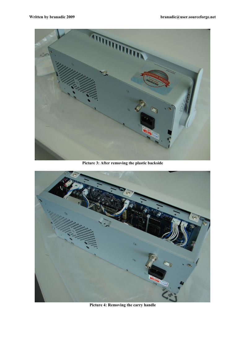
Picture 3: After removing the plastic backside
Picture 4: Removing the carry handle

Written by branadic 2009 [email protected]
Picture 5: Removing the housing, with a view to the pcb
As you can see, there is a main pcb and a separate board with the FPGA. The complete two analog input stages and the external trigger are beneath a HF-shielding. In the middle of the front is the SD card slot. The quite fan is placed at the side wall. At the back wall of the case are the switching power supply and a board with the USB port for pc connection and the self calibration output (BNC connector).

Written by branadic 2009 [email protected]
Picture 6: Main pcb with the FPGA pcb
Picture 7: The FPGA pcb is connected via three pinheads
Written by branadic 2009 [email protected]
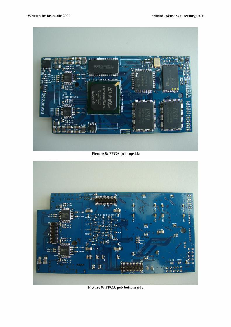
Picture 8: FPGA pcb topside
Picture 9: FPGA pcb bottom side

Written by branadic 2009 [email protected]
The FPGA board is assembled with the following parts:
- FPGA: 1x Altera Cyclone III EP3C16F484C8N- CPLD: 1x Altera MAX II EPM240T100C5N- ADC: 4x Analog Devices AD9288 BSTZ-100 (Dual 8-bit, 100MSPS)- SRAM: 2x ISSI IS61LPS25636A-200TQLI- SRAM: 1x ISSI42S16800E-7TL - Flash Memory: 1x AMIC A29L160AUV-70F (2M x 8bit)
Picture 10: Beneath the shielding
Here are the input stages of the two channels and on the left the external trigger.There are different ICs, like 3x AD8000YRDZ, 1x OPA132UA obviously for DC coupling, 1x AD8184ARZ - Maybe for setting the gain to different values? I'm not sure. - several transistors and passive parts. The same PhotoMOS relay from NAIS AQY210 as used in Welec scopes for switching between AC and DC coupling can be seen. The input stage also comes with 2 relays, switching the dividers for the vertical scale.A more detailed picture of the input stage can bee seen on the next page.

Written by branadic 2009 [email protected]
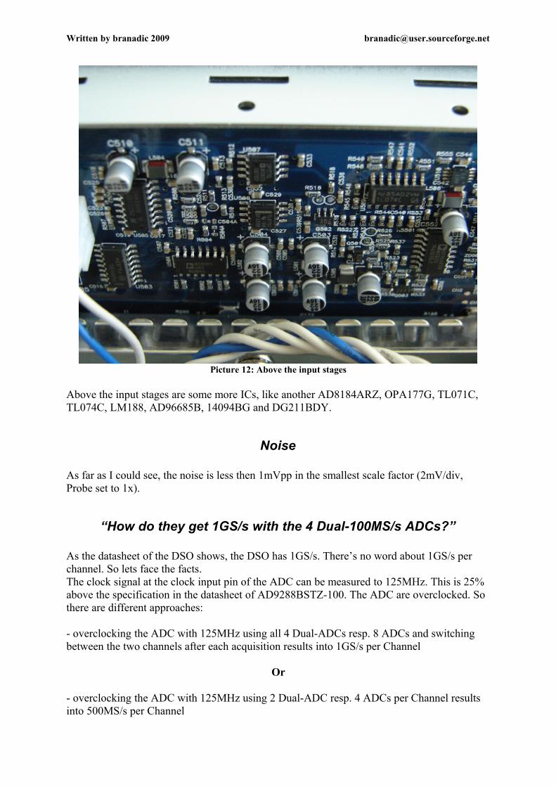
Picture 12: Above the input stages
Above the input stages are some more ICs, like another AD8184ARZ, OPA177G, TL071C, TL074C, LM188, AD96685B, 14094BG and DG211BDY.
Noise
As far as I could see, the noise is less then 1mVpp in the smallest scale factor (2mV/div, Probe set to 1x).
“How do they get 1GS/s with the 4 Dual-100MS/s ADCs?”
As the datasheet of the DSO shows, the DSO has 1GS/s. There’s no word about 1GS/s per channel. So lets face the facts.The clock signal at the clock input pin of the ADC can be measured to 125MHz. This is 25% above the specification in the datasheet of AD9288BSTZ-100. The ADC are overclocked. So there are different approaches:
- overclocking the ADC with 125MHz using all 4 Dual-ADCs resp. 8 ADCs and switching between the two channels after each acquisition results into 1GS/s per Channel
Or
- overclocking the ADC with 125MHz using 2 Dual-ADC resp. 4 ADCs per Channel results into 500MS/s per Channel

Written by branadic 2009 [email protected]
Let find out...
Switching to dots instead of vectors and making a single shot of a 100MHz sinus signal answers the question. We set timebase to 1ns/div and count the samples. There are only 5 data points per period equal to 500MS/s for one channel in real-time mode.
Aquire menu
A view into the aquire menu shows funny things: The entry of the actual sample rate, which is cased by equivalent-time sample mode, displays 1GS/s up to 250ns/div. If you decrease the timebase you can see sample rates of 2.5GS/s, 5GS/s, 10GS/s and 25GS/s. There is no clear border between real-time sample mode and equivalent-time sample mode.
FreeWave PC Software
Signal capture software named FreeWave 2.05 can be downloaded at the GW Instek homepage. Therefore you need to install the USB driver, also available at the homepage. While testing it was not possible to force the software to a screenshot or data transfer. What a pity, I was interested in the sample depth for one active channel and data export would have cleared what's up.
Summary
As shown above, the hardware of the DSO looks great at first view. Components used are very interesting, like AD8000 with only 1.6nV/Hz. The shielding looks pretty deliberate, the whole case is made of metal and plastic fronts are only for good looking. Also the idea of separating the analog from the digital circuit by two boards is kind of smart. Maybe this is caused by the different available versions of analog bandwidth (60MHz / 100MHz / 150MHz). It is also possible, that in future the DSO comes up with higher sample rates?
The real-time sample rate per channel is effectively 500MS/s. The given sample depth of 2MB is for both channels. I’m not sure, whether the whole 2MB can be used in a single channel mode. While testing data export didn’t work with the supplied software, so I couldn’t figure that out.Altogether the hardware of the DSO leaves a great mark, but things are not always the way they seem to be.
Thanks for reading.Your’s branadic