h. haseroth june 5, 2003 nufact03 1 neutrino factory r&d in europe helmut d. haseroth cern,...
TRANSCRIPT

H. HaserothJune 5, 2003 NuFact03
1
Neutrino Factory R&D in Europe
Helmut D. Haseroth
CERN, Geneva, Switzerland
or the art to talk for half an hour about nothing…

H. HaserothJune 5, 2003 NuFact03
2
Organisation of European R&D:
Previously the CERN Neutrino Factory Working Group was quite active together with other European labs.
Then came (BIG surprise?) the LHC catastrophy…Huge reduction in accelerator R&D
CLIC cut drastically (to around 4 MCHF)
SPL down to around 200 k€
Neutrino Activity down to a bit of travel money
(That‘s why I am still here…)
H. HaserothJune 5, 2003 NuFact03
3
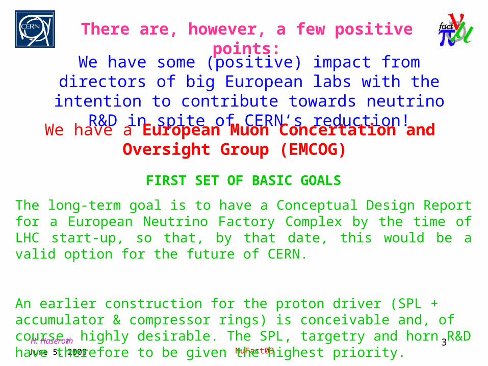
There are, however, a few positive points:
We have some (positive) impact from directors of big European labs with the intention to contribute towards neutrino R&D in
spite of CERN‘s reduction!
FIRST SET OF BASIC GOALS
The long-term goal is to have a Conceptual Design Report for a European Neutrino Factory Complex by the time of LHC start-up, so that, by that date, this would be a valid option for the future of CERN.
An earlier construction for the proton driver (SPL + accumulator & compressor rings) is conceivable and, of course, highly desirable. The SPL, targetry and horn R&D have therefore to be given the highest priority.
We have a European Muon Concertation and Oversight Group (EMCOG)
H. HaserothJune 5, 2003 NuFact03
4
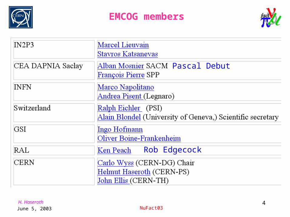
Rob Edgecock
Pascal Debut
EMCOG members
H. HaserothJune 5, 2003 NuFact03
5
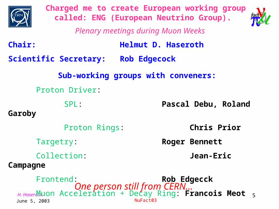
Charged me to create European working group called: ENG (European Neutrino Group).
Plenary meetings during Muon Weeks
Chair: Helmut D. Haseroth
Scientific Secretary: Rob Edgecock
Sub-working groups with conveners:
Proton Driver:
SPL: Pascal Debu, Roland Garoby
Proton Rings: Chris Prior
Targetry: Roger Bennett
Collection: Jean-Eric Campagne
Frontend: Rob Edgecck
Muon Acceleration + Decay Ring: Francois Meot
One person still from CERN…

H. HaserothJune 5, 2003 NuFact03
6
MUON Weeks
MUON Weeks: Organized by V. Palladino:
3/year at different locations in Europe at participating labs. Covers physics and machine aspects.
Resources at all European labs (manpower and money) very limited => ask the EU for support!
No hope in the past for support from EU neither for high energy physics nor for accelerators,
especially not for CERN.
H. HaserothJune 5, 2003 NuFact03
7
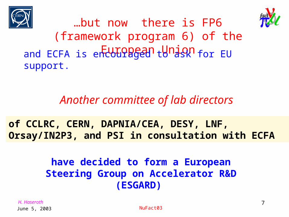
…but now there is FP6 (framework program 6) of the European Union
and ECFA is encouraged to ask for EU support.
Another committee of lab directors
of CCLRC, CERN, DAPNIA/CEA, DESY, LNF, Orsay/IN2P3, and PSI in consultation with ECFA
have decided to form a European Steering Group on Accelerator R&D
(ESGARD)

H. HaserothJune 5, 2003 NuFact03
8

H. HaserothJune 5, 2003 NuFact03
9
Two Contact Groups (CG) issued from ESGARD have been set up to bidding preparation, one of electron-positron linear colliders and one on super proton accelerators and neutrino beams. These CGs will create Working Groups (WG) with the people of the community involved in the relevant activities. They also maintain close contact with existing committees, boards and teams. The mandate of the CGs is to:
1.To act as liaison between ESGARD and the community involved in accelerator studies related to the selected theme. 2.To inform the relevant community of the proposals being developed on accelerator R&D for FP6 and form a Working Group to :
•Establish a proposal for Networking Activities (NA) related to each theme, •Develop proposals for Joint Research Projects (JRP), •Explore whether Transnational Access (TA) as defined by the EU commission is applicable to the accelerator community and, if so, make a proposal,
3.Together with the WG and in consultation with ESGARD, propose the names of the coordinators for the different activities (NA, TA and JRP). 4.Investigate with the WG whether proposals for Design Studies (DS) and/or Construction of New Infrastructures (CNI) as defined by the EU commission is applicable and identify their scope.
•Contact Group 1 on e+e- Linear Colliders : A. Antonelli, G. Guignard, F. Richard, S. Smith and D. Trines
•Contact Group 2 on super proton-accelerators and neutrino beams : R. Aleksan, H. Haseroth, P. Norton and A. Wrulich

H. HaserothJune 5, 2003 NuFact03
10
The R&D on accelerators for high energy physics is organised around three main future world-wide projects:
1.Electron-positron linear colliders with energies ranging between 500 and 3000 GeV in the centre-of-mass system, using the technology of superconductive high gradient accelerator structures recently developed by the TESLA international collaboration, and aiming at exploiting as well the two-beam technique for obtaining ultra-high gradients at room temperature developed by the CLIC international collaboration. 2.Facilities providing intense neutrino beams (see for example NUFACT, using both improvements to the existing methods based on intense proton beams, and the more novel techniques based on radioactive ion or muon beams.3.Facilities providing proton beams with ultra-high intensities and energies, aiming at very large hadron colliders, and covering as well luminosity and energy upgrades of the LHC at CERN.
Neutrino Factories are part of ESGARD activities

H. HaserothJune 5, 2003 NuFact03
11
From the minutes of the Restricted ECFA, November 29, 2002
The chairman thanked R.Aleksan and ESGARD for the enormous amount of work they have already done as well as M.Spiro who has set the project going (Applause). RECFA fully supports the steps taken by ESGARD in building up the bids and will closely follow its work
Statement made in the Chairman's Summary of Conclusions of the December 2002 SPC meeting at CERN
The SPC strongly supported the effort to co-ordinate the accelerator R&D at the European level through the promotion of the ESGARD initiative to get support of the European Union.
From the minutes of the Restricted ECFA, March 31, 2003
RECFA was impressed by the huge amount of work done by ESGARD and congratulated them for having so successfully built the proposal on accelerator R&D to the 6th EU Framework Programme. This proposal includes 6 Joint Research Projects and 3 Networks Activities, which are all considered with high priority by RECFA

H. HaserothJune 5, 2003 NuFact03
12
Vittorio Palladino
Not a lot of money for these activities. Typically 1 to 1.5 M€ for 5 years!

H. HaserothJune 5, 2003 NuFact03
13
A possible proton driver for a Neutrino Factory

H. HaserothJune 5, 2003 NuFact03
14
CERN Scheme

H. HaserothJune 5, 2003 NuFact03
15
SPL basics
Study group since 1999 design of a Superconducting Proton Linac (H-, 2.2
GeV). higher brightness beams into the PS for LHC intense beams (4 MW) for neutrino and
radioactive ion physics
H-
RFQ RFQ1 chop. RFQ2DTL CCDTL RFQ1 chop. RFQ2 0.52 0.7 0.8 dump
Source Low Energy section DTL Superconducting section
95 keV 3 MeV 7 MeV 120 MeV 2.2 GeV
40MeV 237MeV
6 m 64 m 584m
PS / Isolde
Stretching andcollimation line
Accumulator Ring
383MeV
chopping
4 m
660 m
CERN 2000-012

H. HaserothJune 5, 2003 NuFact03
16
SPL design parameters
H-
RFQ RFQ1 chop. RFQ2 RFQ1 chop. RFQ2 0.52 0.7 0.8 dump
Source Low Energy section DTL Superconducting section
45 keV 3 MeV 120 MeV 2.2 GeV
40MeV 237MeV
6 m 64 m 584 m
PS / Isolde
Stretching andcollimation line
Accumulator Ring
Debunching
383MeV
668 m
DTL CCDTLchopping
For neutrino physics, it has to be compressed with an
Accumulator and aCompressor ring into
140 bunches, 3 ns long,forming a burst of 3.3 s
Ion species H-Kinetic energy 2.2 GeVMean current during the pulse 13 mADuty cycle 14.0 %Mean beam power 4 MWPulse frequency 50 HzPulse duration 2.80 msDuty cycle during the beam pulse 61.6 %Maximum bunch current 22.7 mABunch length (total) 0.5 nsEnergy spread (total) 0.5 MeVNormalised rms horizontal emittance 0.4 mm mradNormalised rms vertical emittance 0.4 mm mradLongitudinal rms emittance (352 MHz) 0.3 deg MeV

H. HaserothJune 5, 2003 NuFact03
17
A large inventory of LEP RF equipment is available (SC cavities, cryostats, klystrons, waveguides, circulators, etc.)which can drastically reduce the cost of construction
LEP cavity modules in storage
Stored LEP klystrons

H. HaserothJune 5, 2003 NuFact03
18
SPL lay-out

H. HaserothJune 5, 2003 NuFact03
19
SPL cross section

H. HaserothJune 5, 2003 NuFact03
20
Accumulator and Compressor Rings (“PDAC”)
T= 2.2 GeVIDC = 13 mA (during the pulse)IBunch= 22 mA3.85 108 protons/bunchlb(total) = 44 ps*H,V=0.6 m r.m.s
(140 + 6 empty)per turn
845 turns( 5 140 845 bunches per pulse)
no beam
2.8 ms
20 ms
140 bunches
20 ms
3.2 s
Charge exchangeinjection
845 turns
PROTON ACCUMULATORTREV = 3.316 s
(1168 periods @ 352.2 MHz)
1 ns rms(on target)
22.7 ns
TARGET
H+140 bunches1.62 1012 protons/bunchlb(rms) = 1 ns (on target)
Fast ejection
KICKER20 ms
3.3 slb(total) = 0.5 ns
DRIFT SPACE+
DEBUNCHER
H-
11.4 ns
22.7 ns
5bunches
Fast injection(1 turn)
BUNCH COMPRESSORTREV = 3.316 s
(1168 periods @ 352.2 MHz)
BUNCHROTATIONRF (h=146)
Fast ejection
RF (h=146)
3 emptybuckets
17.2 ms
2 synchrotron ringsin the ex-ISR tunnel

H. HaserothJune 5, 2003 NuFact03
21
Roadmap (1): 3 MeV injector
1) 3 MeV pre-injector 2006 at CERNOn-going collaboration with CEA (Saclay-F) and CNRS (Orsay-F) to
build, test and install at CERN a 3 MeV pre-injector based on the “IPHI” RFQ (Injecteur de Protons de Haute Intensité)
E C R S IL H I sou rcean d L E B T
R F Q H E B T w ithB e a m D ia g n o stic s
sp ectrom eter
B e a mS top p er
B ea m P o w er : 3 0 0 k W
9 5 K e V
2 R F S y s te m s3 5 2 M H z - 1 .3 M W
3 M e V
1 0 0 K VH V p la tform
8,6 m 6 m 14 m

H. HaserothJune 5, 2003 NuFact03
22
Roadmap (2): Linac4
Idea: Take only the room temperature part of the SPL (120 MeV) and install it in the PS South Hall, to inject H- into the PS
Booster > twice the number of protons/pulse in the PSB
(5 1013)
H-
RFQ RFQ1 chop. RFQ2DTL CCDTL
95 keV 3 MeV 120 MeV 150 MeV
40MeV 6 m 64 m
chopping
4 m
SCL/SC
120 MeV, 80m, 16 LEP klystrons

H. HaserothJune 5, 2003 NuFact03
23
Linac4 layout in South Hall
"NEW LINAC" Layout in the PS South Hall - version 5.2.2002
12.0
m
PS Access
RF Workshop
Loading Area
Storage AreaRFQ Test stand352 MHz Test StandLoading
Area
to inflector & PSB

H. HaserothJune 5, 2003 NuFact03
24
HIPPI
In the frame of the CARE Initiative (ESGARD), Joint Research Activity called HIPPI (High Intensity Pulsed proton Injector) (total 6 JRA’s)
8 European Laboratories join efforts for a common R&D on high intensity linacs with energy in the range 3-200 MeV (CEA, CERN, ISN-Grenoble, GSI, IAP-Frankfurt, FZ Juelich, RAL, INFN-Mi) to prepare the upgrade of the proton accelerator facilities at CERN, GSI, RAL
4 Work Packages: 1. Normal-conducting accelerating structures2. Superconducting accelerating structures3. Beam chopping4. Beam dynamics
Total investment of some 15 M€ (including lab salaries), request to EU for a contribution of 4 M€ over 5 years (2004-08)
For CERN, this means 130 k€/yr (…).

H. HaserothJune 5, 2003 NuFact03
25
R&D Topics - CCDTL
CCDTL = Cell Coupled Drift Tube Linac, a simpler and cheaper alternative to DTL for energy > 40 MeV
quadrupolecoupling cell
DTL-like accelerating cell(2 or 3 drift tubes)
CCDTL prototype

H. HaserothJune 5, 2003 NuFact03
26
• LEP RF cavities are getting older...
• New technology can provide better performance (=gradient!)
• More EU-wide interest on 700 MHz frequency, bulk Nb
• Consequences:
1. Slowly relax the option on the LEP cavities
2. Consider 700 MHz already for the 100-150 MeV at Linac4.
3. Start market survey for 700 MHz klystrons
4. R&D options must be valid for both frequencies
Roadmap (3): SPL …
H. HaserothJune 5, 2003 NuFact03
27
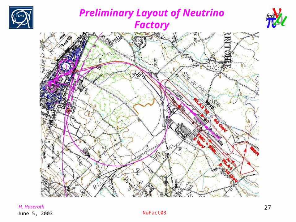
Preliminary Layout of Neutrino Factory

H. HaserothJune 5, 2003 NuFact03
28
European Scenarios
SPL + accumulator and compressor rings
5 GeV, 50 Hz synchrotron-based system
15 GeV, 25 Hz synchrotron-based system
30 GeV, 8 Hz slow cycling synchrotron
8 GeV, 16.67 Hz rapid cycling synchrotron for
ISIS/Fermilab, plus upgrades

H. HaserothJune 5, 2003 NuFact03
29
CERN PDAC: Bunch Compression

H. HaserothJune 5, 2003 NuFact03
30
180 MeV H- Linac
Two 1.2 GeV, 50 Hz Rapid Cycling Synchrotrons
2 bunches of 2.5 1013 protons
4 bunches of 2.5 1013 protons
Two 5 GeV, 25 Hz Rapid Cycling Synchrotrons
Collimation
Injection
Momentum Ramping
RAL 5 GeV Proton Driver

H. HaserothJune 5, 2003 NuFact03
31
ISIS MW Upgrades and possible use as a NF test bed
800 MeV,160 kW, 50 Hz, spallation neutron source
Current upgrade to 240 kW with new ion source, RFQ and dual harmonic RF accelerating system

H. HaserothJune 5, 2003 NuFact03
32
Stage 1: upgrade to 1MW neutrons
Addition of a new synchrotron to increase beam energy to 3 GeV at 50 Hz
Operated at 16.67 Hz, with every third ISIS pulse, could take beam to 8 GeV and be used as a test bed for 1 ns bunch compression

H. HaserothJune 5, 2003 NuFact03
33
Stage 2: Upgrade to 4-5 MW Design and build new linac and two
new booster synchrotrons with radius 39 m, operating at 50 Hz to 1.6 GeV (h=3)
Build a second 78 m racetrack Operate the two racetracks at 25Hz
on alternate cycles 2MW beam power in each rings
4MW neutron source 2MW to neutron target
+ 2MW to pion target 4MW to pion target
78m radius
39m radius
180 MeV Linac

H. HaserothJune 5, 2003 NuFact03
34
Current StatusCERN have had considerable success with studies of mercury jets (with BNL), including within solenoidal fields.
CERN are are also studying granular targets.
PSI are building a liquid metal target. They are involved with the US in liquid metal targets for high power spallation sources.
RAL has done preliminary tests on shock waves in hot tantalum using electron beams.
CERN ISOLDE have experience of the problems of radioactivity and of shock waves. They have a laboratory suitable for handling active materials and molten metals - mercury.
CERN, PSI (not pulsed) and RAL have facilities providing high power proton beams. Also in the US at Los Alamos, Brookhaven and FNAL.
Target Studies
H. HaserothJune 5, 2003 NuFact03
35
The Liquid Metal (Mercury) JetThe jet is constantly being reformed for every pulse. The jet becomes “heated” by the beam and disperses to hit the walls
No Problems with:
• Radiation Damage
• Shock Damage
• Power dissipation
Possible Problems with:
• Jet formation
• Interaction with the magnetic field
• Interaction of the mercury with other equipment
Tests to date indicate that the jet is viable

H. HaserothJune 5, 2003 NuFact03
36
Hg-jet p-converter target with
a pion focusing horn

H. HaserothJune 5, 2003 NuFact03
37
Proposed rotating tantalum target ring
Targetry
Many difficulties: enormous power density lifetime problems pion capture
Replace target between bunches:
Liquid mercury jet or rotating solid target
Stationary target:
Densham Sievers

H. HaserothJune 5, 2003 NuFact03
38
Granular Target

H. HaserothJune 5, 2003 NuFact03
39
A Water Cooled Cu-Ni Rotating Band Target (BNL and FNAL,
Bruce King)
A Radiation Cooled Rotating Toroid, (RAL)•TOROID OPERATES AT 2000-2500 K
•RADIATION COOLED
•ROTATES IN A VACUUM
•VACUUM CHAMBER WALLS WATER COOLED
•NO WINDOWS
•SHOCK? Pbar target OK. Tests using electron beam simulation indicate no problem.
H. HaserothJune 5, 2003 NuFact03
40
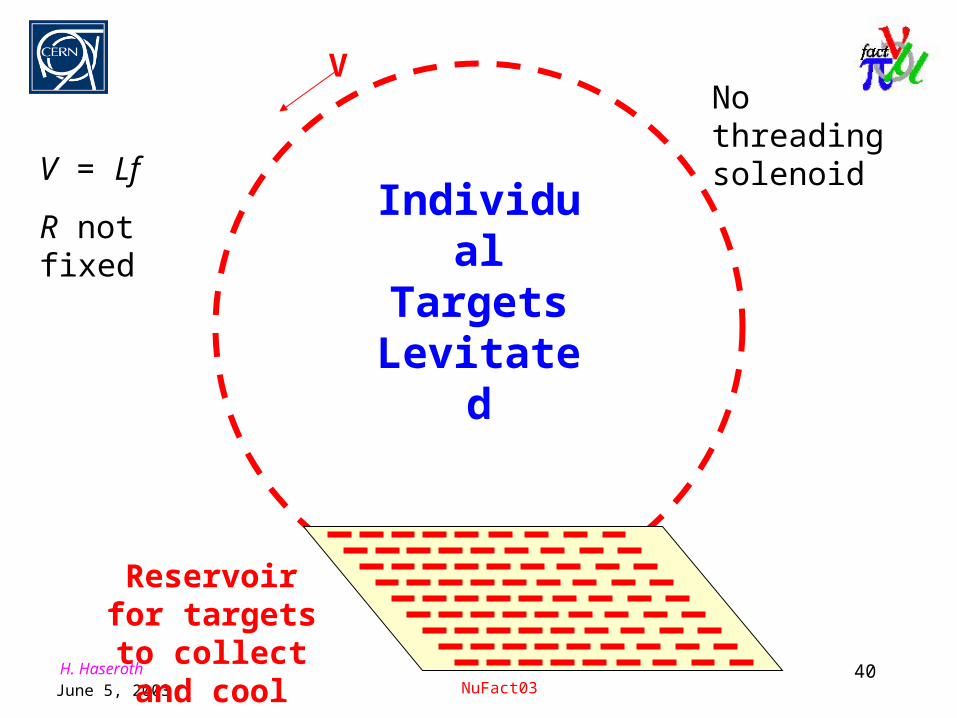
Individual Targets
Levitated
V
Reservoir for targets to collect
and cool
V = Lf
R not fixed
No threading solenoid

H. HaserothJune 5, 2003 NuFact03
41
Advantages of Solid Target•No windows
•Cooling in the walls
•Simple concept
Disadvantages•Large rotating toroid or individual targets
•Problems if toroid breaks
•Thermal shock - toroid breaks
•Very radioactive

H. HaserothJune 5, 2003 NuFact03
42
Tests by RAL with electron beams show that tantalum foils can withstand at least 200000 pulses and have lasted for 1000000.

H. HaserothJune 5, 2003 NuFact03
43
Collector
1. Solenoid, 10-20 Tesla
US consider they have a long life (>1 year) design
2. Horn
Problems with: Heat dissipation, Radiation damage, Stress Possible 6 week life Studies will continue

H. HaserothJune 5, 2003 NuFact03
44
Double horn concept
B field
0.001
0.01
0.1
1
1 100
Radius (mm)
B (
a.u
.) I = 300 kAI = 600 kASum

H. HaserothJune 5, 2003 NuFact03
45
Horn prototype ready for tests
H. HaserothJune 5, 2003 NuFact03
46
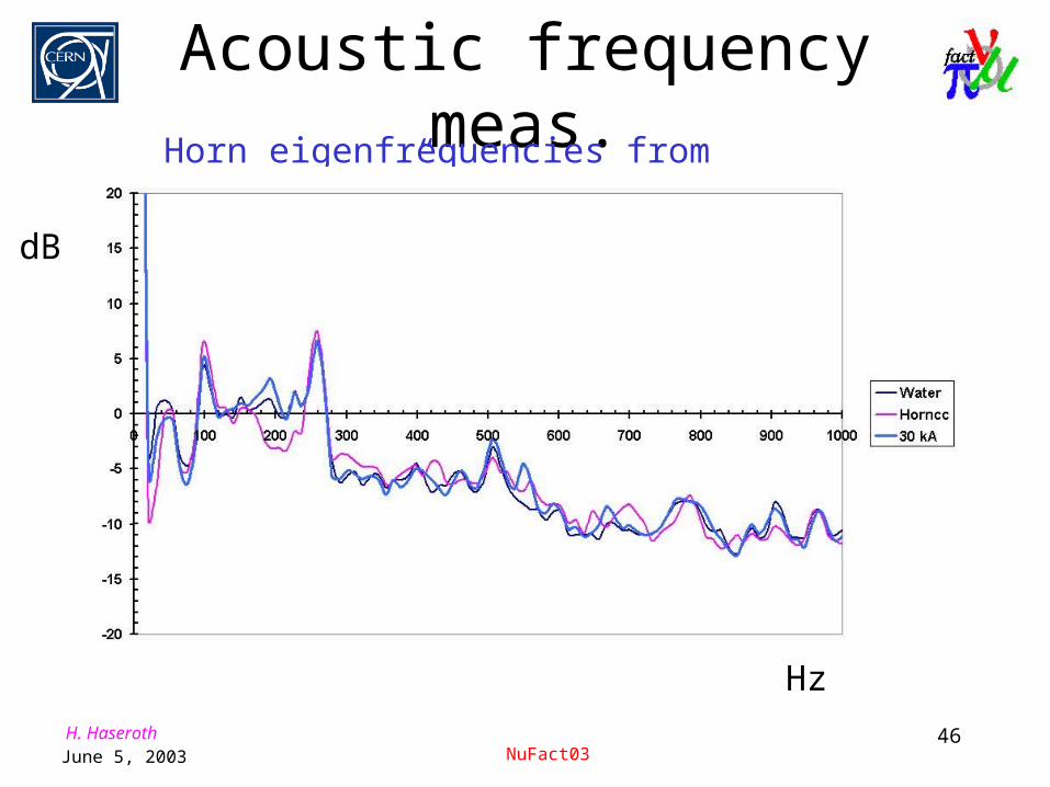
Acoustic frequency meas.Horn eigenfrequencies from horn “sound”
Hz
dB

H. HaserothJune 5, 2003 NuFact03
47
What we planned to do• First “inner” horn 1:1 prototype • Power supply for Test One:
30 kA and 1 Hz, pulse 100 s longFirst mechanical measurements Test of numerical results for vibration Test of cooling system
• Test Two: 100 kA and 0.5 Hz, 100 s long– test of this power supply during last weeks
• Last test: 300 kA and 50 Hz Unknown
schedule
Goal: Horn Life-Time 6 weeks (2*108 pulses)

H. HaserothJune 5, 2003 NuFact03
48

H. HaserothJune 5, 2003 NuFact03
49
Hg-jet system• Power absorbed in Hg-jet
1 MW• Operating pressure 100 Bar• Flow rate 2 t/m• Jet speed 30 m/s• Jet diameter 10 mm• Temperature
- Inlet to target 30° C- Exit from target 100° C
• Total Hg inventory 10 t• Pump power 50 kW

H. HaserothJune 5, 2003 NuFact03
50
If you do not like this…
Try funneling!B. Autin, F. Meot, A.
Verdier

H. HaserothJune 5, 2003 NuFact03
51
What are the problems?• Proton beam power: 4 MW
• Target to cope with high power(must be a high Z target because of the modest proton energy)
• Horn to be pulsed at: 50 Hz(Linac frequency)
•It would be much simpler if we had only 1 MW and e.g. 12.5 Hz

H. HaserothJune 5, 2003 NuFact03
52
How does it work?• The proton beam is switched to 4 targets in sequence.• Each of the 4 pion lines contains an integrated system of
target and magnetic horn.• The funnel is made of large aperture magnets with
quadrupolar and pulsed dipolar coils.
•No exotic and expensive technology.
•Lifetime in excess of one year.
•Evolutionary design.
Why a funneling system?

H. HaserothJune 5, 2003 NuFact03
53
Funneling step by step
H. HaserothJune 5, 2003 NuFact03
54
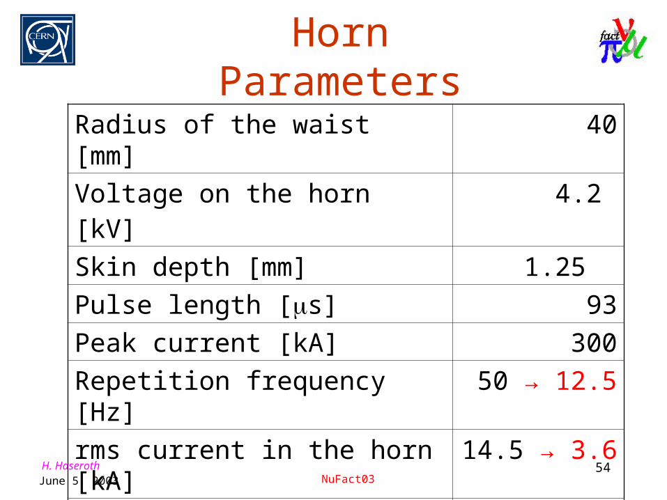
Horn Parameters
Radius of the waist [mm] 40
Voltage on the horn [kV] 4.2
Skin depth [mm] 1.25
Pulse length [s] 93
Peak current [kA] 300
Repetition frequency [Hz] 50 → 12.5
rms current in the horn [kA] 14.5 → 3.6
Power dissipation by current [kW] 39 → 9.7

H. HaserothJune 5, 2003 NuFact03
55
Target dynamics
• High repetition frequency f reduces instantaneous energy deposited W at given power P: W = P/f .
• Long pulse heats the spheres adiabatically: no shock.
Without funneling
With funneling
0.2 0.4 0.6 0.8 1ts50
100
150
200
250
TK
H. HaserothJune 5, 2003 NuFact03
56
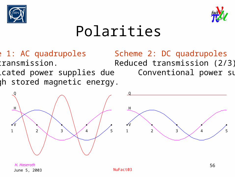
Polarities
Scheme 1: AC quadrupoles Scheme 2: DC quadrupolesGood transmission. Reduced transmission (2/3).Complicated power supplies due Conventional power supplies.to high stored magnetic energy.
Q
H
V1 2 3 4 5
Q
H
V1 2 3 4 5

H. HaserothJune 5, 2003 NuFact03
57
Muon production• Y = N/Nversus longitudinal emittance for two transverse admittances:
t = 1 cm (no cooling)
t = 4 cm (cooling)
0.5 1 1.5 2l eV.s
5
10
15
20
Y%
t cm 1
t cm 4
High field AG line
Conventional AG line
Solenoid

H. HaserothJune 5, 2003 NuFact03
58
IntroductionIntroduction
FrontendFrontend

H. HaserothJune 5, 2003 NuFact03
59
CERN Baseline FrontendCERN Baseline Frontend
Replaced with an all 88MHz frontend Replaced with an all 88MHz frontend eliminates 44MHz eliminates 44MHz cavities cavities
target
and horn
:
as
before
15 m dec
ay ch
annel
7.2 m phase
rotat
ion
coolin
g (6.4 m
/cell)
80 MHz
Decay Rotation Cooling I Acceleration I
Acceleration II
Length [m] 15 8 90 10 450
Diameter [cm] 40 40 40 30 20
B-field [T] 4 4 4 4 quads
Frequency [MHz] 80 80 80 80-200
Gradient [MV/m] 4 4 4 4-10
Kin Energy [MeV] 200 200 300 2000
Same performance Same performance as 44/88MHz as 44/88MHz
channelchannel

H. HaserothJune 5, 2003 NuFact03
60
Frontends without CoolingFrontends without Cooling
Grahame Rees et alGrahame Rees et al
Muon Front Ends Decay Region .2 GeV
44 MHz Rotation .2 GeV
44 MHz Cooling .2 GeV
44 MHz Accel’n .28 GeV
88 MHz Cooling & Acceleration .4 GeV 286.0 m
Decay Region .19 GeV
88 MHz Rotation .19 GeV
88 Mhz Acceleration .4 GeV 132.7 m
Decay Region .19 GeV
Reverse Rotation .19 GeV
88 MHz Acceleration .4 GeV 128.0 m
Pion-muon decay channel
88 MHz muon linac

H. HaserothJune 5, 2003 NuFact03
61
Frontends without CoolingFrontends without Cooling
Solenoid
channel
Es=190MeV
RF phase
rotation
channel
Es=190MeV
Linac
Es=400MeV
(Transmission
=77%)
Solenoid
channel
Es=190MeV
Inverse
rotation
channel
Es=190MeV
Linac
Es=400MeV
Transmission comparable to 44/88MHz scheme

H. HaserothJune 5, 2003 NuFact03
62
AG Phase RotationAG Phase Rotation
Jaroslaw Pasternak et alJaroslaw Pasternak et al
• Extend AG structure to phase rotation:Extend AG structure to phase rotation: - 8 - 8 triplet FODO cells matched to decay channeltriplet FODO cells matched to decay channel
• Add magnetic compression chicane:Add magnetic compression chicane:- 2 periods, each 3 FODO cells- 2 periods, each 3 FODO cells
1.8x increase1.8x increase

H. HaserothJune 5, 2003 NuFact03
63
RingsRings
S = solenoid, A = absorber, 36 cavities in blocks of 3
Grahame Rees et alGrahame Rees et al
• Hybrid ring, using solenoids and dipolesHybrid ring, using solenoids and dipoles
• 44m circumference: 18m straights, 4m bends44m circumference: 18m straights, 4m bends
• 4m sections for injection and extraction4m sections for injection and extraction
• Initial results looking promisingInitial results looking promising
H. HaserothJune 5, 2003 NuFact03
64
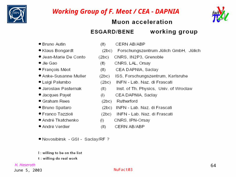
Working Group of F. Meot / CEA - DAPNIA

H. HaserothJune 5, 2003 NuFact03
65
Working Group of F. Meot / CEA - DAPNIA
Design studies - Plans for the future a full design of a single- or double-RLA,a full design of an FFAG ring - 6D tracking, DA, etc.polytron scheme ?converge on, finalise muSR designin all cases, perform tracking simulations end to endneed develop simulation (including tracking) tools"These acceleration systems are the largest cost items in the system" [DN,Acceleration for the mu-storage ring neutrino-source]prime goal : reduce costs

H. HaserothJune 5, 2003 NuFact03
66
Some time ago regarded by some people as science fiction, it must be noted that the advances in cooling theory and technology are so impressive as to consider this type of machine as a real possibility in the future.
Muon Colliders
High Energy Frontier…

H. HaserothJune 5, 2003 NuFact03
67
300 MeV Neutrinos
small contamination from e (no K at 2 GeV!)
A large underground water Cerenkov (400 kton) UNO/HyperK is best choicealso : proton decay search, supernovae events solar and atmospheric neutrinos.
Possible step 0: Neutrino SUPERBEAM
Fréjus underground lab.

H. HaserothJune 5, 2003 NuFact03
68
EURISOL
NUFACT (superbeam/neutrino factory)
isol production of rare ions
+betabeam acceleration to (CERN)
4 MW target station collection, horn
Cooling muon acceleration and
storage + proton/H- driver nuclear-synergy group
NA : BENE
Large cavern and UNO
proton driver
Design studies (preliminary thoughts)
Driver
Post-accelerator
Mass separator
5 MW target Scientific instrumentation

H. HaserothJune 5, 2003 NuFact03
69
Many thanks to my European colleagues for their help to prepare this talk, in particular to:
R. Aleksan
R. Garoby
Ch. Prior
R. Bennett
S. Gilardoni
B. Autin
R. Edgecock
F. Méot
M. Lindroos
and many others…