h j - cemo...non-conductive substructure, potential equalization has to be included using a mobile...
TRANSCRIPT

Cable feedth-rough for pump electrical cable
ADE Declaration of conformity from the company Capri according to EC directive 94/9/EC as well as the ATEX certificate of the Industries Electriques Laboratoire Central dated 14 Sep. 1998 with the ID EX 112 G et D
Safety valve
Component ID: TÜV.SV. 07.101.5.7.D/G 0.67 0.5 bar CE 0045
6 Expert examinationThe signer of the certificate appraised various type systems with the system parts described above on October 11, 2007.
7 Comments on the subject of inspectionThe systems consist of a double-walled leak-monitored tank which has received approval according to traffic law. The fittings required for a storage tank such as a fixed filling connection, limit indicator, test valve, ventilation pipe, leakage fluid container with tilt valve and test valve as well as level indication using a fuel dip stick. ATEX certificates exist for the electrical and mechanical devices. Thus the materials meet both the water directive requirements and the requirements pertaining to fire and explosion protection.
Note:It should be noted that, upon installing the system on a non-conductive substructure, potential equalization has to be included using a mobile earth rod or a hard-wired electrical connection. If the on/off switch is installed in the dispensing pump housing, then this switch has to be designed as an explosion prevention model of at least T3. A cable feedthrough in the housing is to be equipped with protective shielding. An emergency-off button is to be installed near the system. The TRbF 40 (filling stati-ons) is to be adhered to with reference to the installation requirements.The manufacturer is to include a system operating manual with delivery.
8 SummaryThe company CHEMOWERK GmbH located in Wein-stadt with the postal code 71384 has commissioned the Singen branch of the Freiburg office of TÜV SÜD Industrie Service GmbH to test the prototype of mobile fuel systems for petrol. Appraisal was able to prove that the system types KS-Mobil 400, KS-Mobil 600 and KS-Mobil 980 for motor fuel meet the requirements of water directive and the trade laws governing fire and explosion protection.
Singen, October 31, 2007
Department of Steam and Pressure Technology of the Singen branch
Authorised expert
Klaus Göllmer
138.0639.305 / 01.08 / Sm CHEMOWERK GmbHIn den Backenländern 5 • D-71384 Weinstadt
Tel. ++49 (0) 71 51/96 36-0 • Fax ++49 (0) 71 51/96 36-98 • www.chemo.de
138.0639.305 / 01.08 / Sm CHEMOWERK GmbHIn den Backenländern 5 • D-71384 Weinstadt
Tel. ++49 (0) 71 51/96 36-0 • Fax ++49 (0) 71 51/96 36-98 • www.chemo.de
CHEMO KS-MOBIL 400, 600D doppelwandig, verzinkt Deutsch 2 - 5
Zulassungs - Nr.: D/BAM 6599-CHEMO/31A 16-20Bericht zur Baumusterprüfung 21-25
GB double-walled, galvanised English 2 - 3, 6 - 7 Approval no.: D/BAM 6599-CHEMO/31A 16-20Type examination 26-28
F double paroi, en acier galvanisé Français 2 - 3, 8 - 9N° d'homologation: D/BAM 6599-CHEMO/31A 16-20
I a doppia parete, zincato Italiano 2 - 3, 10 - 11N. di omologazione: D/BAM 6599-CHEMO/31A 16-20
E de doble pared, galvanizados Español 2 - 3, 12- 13Número de autorización: D/BAM 6599-CHEMO/31A 16-20
CZ dvouplášťový, zinkovaný Česky 2 - 3, 14 - 15Připuštění číslo: D/BAM 6599-CHEMO/31A 16-20

2
B
A
C
D
E
F
G
JH
I
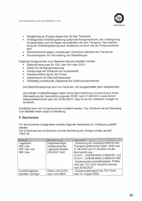
The following components for fuelling can be installed:• Electrical supply pump for 12 V, 24 V or 230 V.• Meter for quantity measurement• Hand pump with hose and tap.• Cable feedthrough for the pump• Filling hose for electrical supply pump• Delivery nozzle with automatic shut-off for electrical
pump operation
The electrical supply pump is switched on and off by hand (no automatic delivery unit).
The mobile fuelling systems have no gas return and thus the gas return rate cannot be monitored according to German Federal Immission Control Regulation 21 nor does it have a gas displacement connection according to German Federal Immission Control Regulation 20. This is only required for stationary systems.
A pump cabinet can also be installed. At the intersec-tion with the container, the housing has an opening for ventilation.
5 ProofThe following proof could be provided for the individual system parts.Classification of the ex-area and evaluation of the system was carried out according to TRbF 40.Unit Designation Proof
Storage tank:400, 600 and 980 litres
Double-walled leak-monito-red storage tank similar to DIN 6623 part 2
- Approval as intermediate bulk container for transpor-ting dangerous materials: BAM (German Federal Ins-titute for Materials Research and Testing) dated 31. Aug. 2004 and 01 Sep. 2004 with the ID:31/A/Y/.../D/BAM 6599-CHEMO/0/* and 31/A/Y/.../D/BAM 6600-CHEMO/0/1458 - explosion, pressure and shock resistance: TÜV SÜD Industrie Service test report dated 20 Aug. 2007
Leaka-ge fluid container with anti-tipping device for transport
Afriso LAS 24 EK or LAS 39EK
- Certificate of approval from TÜV Nord dated 14 Aug. 2002- General Construction In-spection Approval: Z-65.24-381 dated 7 Jul. 2004
Delivery nozzle with automatic shut-off according to DIN 13012 of the company OPW for operation with an electrical pump
OPW 11-A according to DIN 13012
General construction test report PÜ-TÜ7-02240 of the TÜV Nord test laboratory dated 7 Sep. 2004.Labelling OPW/EN13012 Type 1/P-TU7-2240/EX II 2G T3/05 ATEX D056
Electrical supply pumps for 12 V, 24 V and 230 V with overheat protection and meter made by TUTHILL
Fill-Rite series 1200, Fill-Rite series 2400, Fill-Rite series 700
- ATEX certification accor-ding to EC directive 94/9/EC dated 16 Nov. 2004 by Sira Certification Service with the ID EEX dllA T4, T5 or T6- EC declaration of confor-mity from the manufacturer TUTHILL
Hand pump with tap and hose Conti FSL19 with R<106 Ohm made by the company Horn
Horn hand pump model TP3
Declaration of conformity according to EC directive 94/9/EC from the company Horn and pump ID with EXII 2 G EEX c T3 date 1 Dec. 2006
Filling hose for electrical supply pump
Conti Slimli-ne 19 MPD
EN 1360 or TRbF 131 part 2
Limit indicator for tanks according to DIN 6623 part 2 of the company GOK
GWS - General Construction In-spection Approval according to TRbF 511 with the appro-val number Z-65.17-226- EC type examination cer-tificate issued by TÜV Süd dated 19 Feb. 2003 with the ID: EX II 1G ia IIC T4The insertion depth of the limit detector is aligned with design approval stipulations
27
TYPE EXAMINATIONOF MOBILE FUELLING
SYSTEMS FOR MOTOR FUEL
Customer: CHEMOWERKE GmbH In den Backenländern 5 71384 Weinstadt, Germany
Location of operation mobile systems
Subject: Type approval of mobile fuelling systems of the type KS-Mobil 400, KS-Mobil 600 and KS-Mobil 980 for motor fuel
Your order dated: 11 Oct. 2007 Your order number:
Processed by: TÜV Industrie Service GmbH Steam and Pressure Tech-nology Singen Branch Office Klaus Gollmer, Professional Engineer
TÜV order number: 1063472 Date of processing 31 Oct. 2007
The certificate comprises 6 pages 0 attachments
CERTIFICATE
1 AssignmentThe company CHEMOWERK GmbH located in Wein-stadt with the postal code 71384 has commissioned the Singen branch of the Freiburg office of TÜV SÜD Industrie Service GmbH to test the type of mobile fuelling systems.
2 Reason for appraisalThe company CHEMOWERK GmbH would like to have type approval carried out for mobile fuelling systems.
3 Subject of inspectionThis type approval should clarify whether the mobile fuelling system types KS-Mobil 400, KS-Mobil 600 and KS-Mobil 980 adhere to the stipulations of water directives, trade law (fire and explosion protection) and hazardous goods law.
Testing does not include setting up the systems. This should be carried out according to the local conditions according to TRbF 40 (filling stations).
4 Description of the systemsVarious different versions of the mobile fuelling systems are delivered. Selection can be made here with reference to the tank volume, the pump type, with or without meter as well as the pump housing. The storage tank is filled using a fixed filling connection.
The filling stations are not used as public filling stations, but as own-use filling stations.
Storage tanks: 3 container sizes are available: 400, 600 and 980 litres. All of the tanks are constructed with the same wall thickness. The tanks are all double-walled with a visual leak indicator and have received approval accor-ding to traffic law. The storage tanks are all designed to be explosion, shock and compression proof so that flame resistant fittings are not required.
The tanks are equipped with the following fittings:• Leakage fluid container for detection of a leak in the
tank• Test valve to check the flow of leakage fluid• Filling connection with tanker coupling for the road
tanker (outside the pump cabinet)• Fuel dip stick fittings with plastic fuel dip stick and cap• Blockable suction line to pump (for transport)• Extendable ventilation pipe outside of pump cabinet.
The extension can be removed and closed with the cap (for transport). The outlet of the ventilation pipe has to be at least as high as the pump cabinet.
• Safety valve to protect against impermissible overpres-sure during transport
• Limit indicator to prevent overfilling
26 3
D
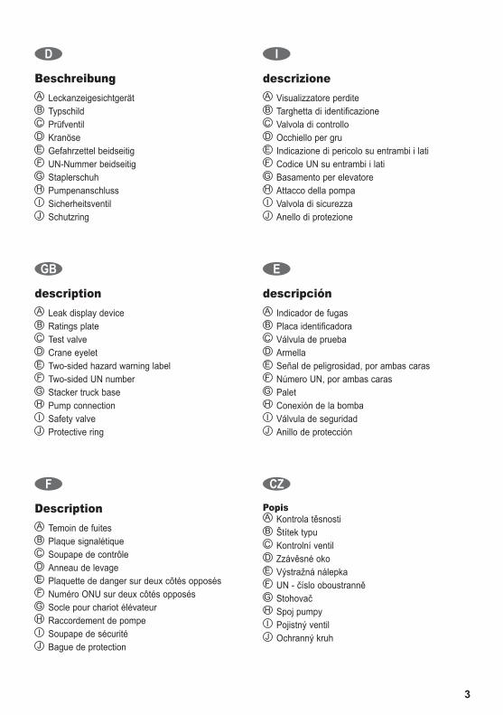
Beschreibung A LeckanzeigesichtgerätB TypschildC PrüfventilD KranöseE Gefahrzettel beidseitigF UN-Nummer beidseitig G StaplerschuhH PumpenanschlussI SicherheitsventilJ Schutzring
GB
description A Leak display deviceB Ratings plateC Test valveD Crane eyeletE Two-sided hazard warning labelF Two-sided UN number G Stacker truck baseH Pump connectionI Safety valveJ Protective ring
F
Description A Temoin de fuitesB Plaque signalétiqueC Soupape de contrôleD Anneau de levageE Plaquette de danger sur deux côtés opposésF Numéro ONU sur deux côtés opposés G Socle pour chariot élévateurH Raccordement de pompeI Soupape de sécuritéJ Bague de protection
I
descrizione A Visualizzatore perditeB Targhetta di identificazioneC Valvola di controlloD Occhiello per gruE Indicazione di pericolo su entrambi i latiF Codice UN su entrambi i lati G Basamento per elevatoreH Attacco della pompaI Valvola di sicurezzaJ Anello di protezione
E
descripción A Indicador de fugasB Placa identificadoraC Válvula de pruebaD ArmellaE Señal de peligrosidad, por ambas carasF Número UN, por ambas caras G PaletH Conexión de la bombaI Válvula de seguridadJ Anillo de protección
CZ
Popis A Kontrola těsnostiB Štítek typuC Kontrolní ventilD Zzávěsné okoE Výstražná nálepkaF UN - číslo oboustranně G StohovačH Spoj pumpyI Pojistný ventilJ Ochranný kruh
4
D
Montage- und Betriebsanleitung
1. Geltende Unterlagen- Betriebsanleitung Handpumpe (Option)- Betriebsanleitung Elektropumpe (Option)- Montageanleitung Kabelverschraubung (Option)- Betriebsanleitung Durchflußzähler (Option)- Betriebsanleitung Leckanzeige-Sichtgerät- Montageanleitung GrenzwertgeberHinweis: Handrad und Schlauch für Prüfventil ist
den Tankpapieren beigelegt.
2. Elektroanschluß der Pumpe zur Stromquelle muß durch einen konzessionierten Elektro-fachmann nach VDE 0100 erfolgen.
- Empfohlenes Kabel: Ölflex- Kabelquerschnitt entsprechend der verwendeten
Pumpe (Spannung)- Kabel Außendurchmesser 6 - 12 mm- Kabeleinführung in die Pumpe gemäß
Montageanleitung Kabelverschraubung
3. AufstellbedingungenDie Aufstellbedingungen sind den wasser-, gewerbe-, und baurechtlichen Vorschriften zu entnehmen.
4. Inbetriebnahme- Den Deckel der Kupplung (Pos. 6) entfernen.
Be- und Entlüftungsrohr (Pos. 1) aufstecken und mittels der Kupplung befestigen.
- Kugelhahn der Entnahmeleitung (Pos. 2) in Stellung „open“ drehen.
- Handpumpe betätigen und Betankungsvorgang beginnen (Option).
- Elektropumpe einschalten, Zapfpistole öffnen und Betankungsvorgang beginnen (Option).
- Die Kontrolle des Füllstands im Behälter erfolgt durch Abschrauben der Peilstabkappe (Pos. 4) und Herausziehen des Peilstabes.
Hinweis: Vor Beginn des Betankungsvorgangs unbedingt Be- und Entlüftungsleitung sowie Kugelhahn der Entnahmeleitung öffnen.
5. Befüllen des BehältersKappe am Befüllstutzen (Pos. 3) abschrauben. Das Betanken des Behälters erfolgt mit festem Füllanschluss. Der Grenzwertgeber (Pos. 5) muss dabei angeschlossen sein. Der Grenzwertgeber ist ab Werk auf eine 95%ige Befüllung eingestellt. Hinweis: Zum Befüllen des Behälters muss die
Be- und Entlüftungsleitung geöffnet sein.
6. Herstellen der Transportbereitschaft- Befüllstutzen (Pos. 3) und Peilkappe (Pos. 4)
dicht verschließen.- Das Be- und Entlüftungsrohr (Pos. 1) an der
Kupplung (Pos. 6) lösen und abnehmen. Mit dem Deckel der Kupplung die Öffnung fest verschlie-ßen.
- Kugelhahn der Entnahmeleitung (Pos. 2) in Stellung „shut“ drehen.
Hinweis: Entsteht bei der Lagerung oder beim Transport im verschlosse-nen Behälter ein Überdruck infolge Temperatureinfluss, so wird dieser über das Sicherheitsventil abgelassen.
7. Wiederkehrende Prüfungen, InspektionenDie CHEMO KS-MOBIL ist nach ADR, 6.5.4.4.1 a), in Abständen von nicht mehr als fünf Jahren einer zuständigen Behörde zufriedenstellenden Inspek-tion im Hinblick auf die Übereinstimmung mit dem Baumuster, einschließlich der Kennzeichnung sowie den inneren und äußeren Zustand und der einwandfreien Funktion der Bedienausrüstung zu unterziehen. Davon ausgenommen ist die Prüfung des Innenraumes. Diese erfolgt erstmals nach zehn Jahren, anschließend alle fünf Jahre.Hinweis: Ein Bericht über jede Inspektion ist
mindestens bis zur nächsten Inspektion vom Eigentümer aufzubewahren.
Der Leckanzeiger ist mindestens einmal jährlich auf Funktion zu prüfen. Dabei ist der Durchlauf der Leck-anzeigeflüssigkeit am Prüfventil entsprechend 3.3 der Betriebsanleitung zum Leckanzeige-Sichtgerät zu prüfen.
Außerdem ist der Behälter nach ADR 6.5.4.4.1 b), in Abständen von höchstens zweieinhalb Jahren einer zuständigen Behörde zufriedenstellenden Inspektion im Hinblick auf den äußeren Zustand und der einwandfreien Funktion der Bedienausrüstung zu unterziehen.
WichtigNach ADR 5.2.1.2 und 5.2.1.4, ist jeder Kraftstoff-container für den Transport deutlich und dauerhaft mit der UN-Nummer des Füllgutes und dem Gefahrzettel beidseitig zu versehen.
Die UN-Nummer 1203 für Benzin und der Gefahrzettel (Flamme auf rotem Grund) sind in zwei-facher Ausführung beigefügt.
25

24
D
5
Übereinstimmungserklärung– Hersteller
Hiermit wird bestätigt, dass das
Bauprodukt:
CHEMO KS-MOBIL mit 380 und 570 Liter Fassungs-raum als IBC (Großpackmittel zu Beförderung gefähr-licher Güter) mit der Zulassungsschein-NummerD/BAM 6599-CHEMO/31Aund der Kennzeichnungs-NummerUN31A/Y/.. ../D/BAM 6599-CHEMO/0/652 (KS-MOBIL 400)UN31A/Y/.. ../D/BAM 6599-CHEMO/0/927 (KS-MOBIL 600)
des
Herstellwerks:
CHEMOD-88605 Meßkirch
entsprechend den Ergebnissen der werkseigenen Produktionskontrolle des Herstellers mit den Anfor-derungen der technischen Regeln der Bauregelliste A Nr. 15.16 und der TRbF 20 Läger und der TRbF 60 ortsbeweglicher Behälter verwendete Tankcontainer übereinstimmt.Desweiteren wird auf die Betriebssicherheitsver-ordnung, speziell §§ 3, 6 und 9, verwiesen.
Verwendungszweck: Sammel-, Transport- und Entnahmebehälter für hochentzündliche, leichtentzündliche und ent-zündliche Flüssigkeiten sowie für Flüssigkeiten mit einem Flammpunkt > 55° C und für nichtbrennbare wassergefährdende Flüssigkeiten, für die ein Werkstoffverträglichkeitsnachweis nach der Positiv-Flüssigkeitsliste DIN 6601 vorliegt. Der IBC ist zum Aufstellen im Freien geeignet.
Das Zertifikat ist in allen Ländern der Bundesrepublik Deutschland gültig.
Weinstadt, den 15. September 2004
Geschäftsführer

GB
Installation and operating instructions
1. Applicable documents- Operating instructions for hand pump (option)- Operating instructions for electric pump (option)- Installation instructions for threaded cable
connection (option)- Operating instructions for flow meter (option)- Operating instructions for leak indicator display unit- Installation instructions for limit indicatorNote: Handwheel and hose for test valve is placed
with the tank documents.
2. Electrical connection of the pump to the power source has to be performed by a certified electrical spe-cialist according to directive VDE 0100 issued by the German Association for Electrical, Electronic & Information Technologies.
- Recommended cable: Ölflex- Cable cross-section according to the pump used
(voltage)- Outside cable diameter 6 - 12 mm- Cable insertion in the pump according to threaded
cable connection installation instructions
3. Installation conditionsThe installation requirements are specified in the legal regulations governing water, commerce and construction.
4. Commissioning- Remove the cover of the coupling (item 6). Attach the
ventilation pipe (item 1) and fasten with the coupling.- Turn the ball valve of the discharge line (item 2) to
the „open“ position.- Operate the hand pump and start the tanking
procedure (option).- Switch on the electric pump, open the delivery
nozzle and start the tanking procedure (option).- The filling level in the container is checked by
unscrewing the dip stick cap (item 4) and remo-ving the dip stick.
Note: Before starting the tanking procedure, the ventilation pipe and the ball valve of the discharge line always have to be opened.
5. Filling the tankUnscrew the cap on the filler neck (item 3). The con-tainer is to be filled using a fixed filling connection.
The limit indicator (item 5) has to be connected for this. The factory setting for the limit indicator is a filling level of 95%.Note: The ventilation pipe has to be open to
fill the container.
6. Preparing the container for transportation- Close the filler neck (item 3) and dip stick cap
(item 4) tightly.- Detach the ventilation pipe (item 1) from the cou-
pling (item 6). Close the opening tightly using the cover of the coupling.
- Turn the ball valve of the discharge line (item 2) to the „shut“ position.
Note: If excess pressure builds up in the closed container during storage or transport due to increased temperature, this pressure is relieved via the safety valve.
7. Periodic tests, inspectionsAccording to ADR, 6.5.4.4.1 a), the CHEMO KS-MOBIL shall be inspected to the satisfaction of the competent authority at intervals not exceeding five years with regard to matching the model including labeling as well as the internal and external condition and the proper functioning of the service equipment. The interior space is excluded from this inspection. This is inspected for the first time after ten years and then subsequently every five years.Note: A report on each inspection is to be kept by
the owner at least until the next inspection.The leak indicator is to be checked for functioning at least once each year. This should include inspection of leak indicator fluid flow at the test valve according to 3.3 of the operating instructions for the leak indicator display unit.
In addition to this, the container should be inspected according to ADR 6.5.4.4.1 b) to the satisfaction of the competent authority at intervals not exceeding two and a half years with regard to its external condition and the proper functioning of the service equipment.
ImportantAccording to ADR 5.2.1.2 and 5.2.1.4, each fuel con-tainer used for carriage must be clearly and indelibly labelled with the UN number of the contents and the hazard label on both sides.
Two copies of the UN number 1203 for petrol and the hazard label (flame on a red background) are enclosed.
6 23

22
GB
7
Declaration of conformity– fabricator
We hereby confirm that the
Product:
CHEMO DT-MOBIL with 380 and 570 litre capacity as an IBC (large container to transport hazardous goods) with the approval certificate number D/BAM 6599-CHEMO/31Aand the identification number UN31A/Y/.. ../D/BAM 6599-CHEMO/0/652 (KS-MOBIL 400)UN31A/Y/.. ../D/BAM 6599-CHEMO/0/927 (KS-MOBIL 600)
of the
manufacturing factory:
CHEMOD-88605 Meßkirch
complies with the requirements of the technical rules in the list of construction rules A No. 15.16 and the TRbF 20 storage and the TRbF 60 mobile container in accordance with the results of the in-plant produc-tion checks performed by the manufacturer.In addition, reference is made to the Plant Safety Regulation, in particular §§ 3, 6 and 9.
Intended use: Collecting, transport and storage tank for highly-flam-mable, easily flammable and flammable liquids and for liquids with a flash point > 55° C and for non-combustible liquids hazardous for water for which a material compatibility certificate in accordance with the list of positive liquids DIN 6601 is available.The IBC is suitable for outdoor installation.
The certificate is valid in all states of the Federal Republic of Germany.
Weinstadt, 15th September, 2004
Managing Director

F
Notice de montage et d‘utilisation
1. Documents applicables- Notice d‘utilisation de la pompe manuelle (option)- Notice d‘utilisation de la pompe électrique (option)- Notice de montage du raccord vissé des câbles (option)- Notice d‘utilisation du débitmètre (option)- Notice d‘utilisation de l‘unité de visualisation de
l‘affichage des fuites- Notice de montage du transmetteur de valeurs limitesRemarque : le volant et le tuyau pour la soupape
de contrôle sont fournis avec les papiers du réservoir.
2. Le branchement électrique de la pompe à la source de courant doit être effectué par un électricien agréé selon la norme VDE 0100.
- Câble recommandé : Ölflex- Section de câble en fonction de la pompe utilisée
(tension)- Câble diamètre extérieur 6 - 12 mm- Introduction de câble dans la pompe selon la
notice de montage du raccord vissé des câbles
3. Conditions d‘installationLes conditions d‘installation sont à recueillir dans les prescriptions sur l‘eau, l‘aménagement du territoire et les constructions.
4. Mise en route- Retirer le couvercle de l‘accouplement (pos. 6).
Enficher le tuyau de ventilation et de purge (pos. 1) et fixer à l‘aide de l‘accouplement.
- Tourner le robinet à boisseau sphérique du con-duit de soutirage (pos. 2) en position « open ».
- Activer la pompe manuelle et commencer le pro-cessus de ravitaillement (option).
- Mettre la pompe électrique en service, ouvrir le pistolet distributeur et commencer le processus de ravitaillement (option).
- Le contrôle du niveau de remplissage dans le réservoir s‘effectue en dévissant le capuchon de la sonde (pos. 4) et en retirant la sonde.
Remarque : Avant le début du processus de ravi-taillement, ouvrir absolument la con-duite de ventilation et de purge ainsi que le robinet à boisseau sphérique du conduit de soutirage.
5. Remplissage du réservoirDévisser le bouchon sur la tubulure de remplissage (pos. 3). Le ravitaillement du réservoir s‘effectue avec un raccord de remplissage fixe. Le transmetteur de valeurs limites (pos. 5) doit être raccordé. Le trans-
metteur de valeurs limites est réglé à l‘usine sur un remplissage à 95 %. Remarque : Pour le remplissage du réservoir, le
tuyau de ventilation et de purge soit être ouvert.
6. Préparation au transport- Fermer hermétiquement la tubulure de remplissa-
ge (pos. 3) et la sonde (pos. 4).- Dévisser le tuyau de ventilation et de purge (pos. 1)
sur l‘accouplement (pos. 6) et le retirer. Avec le cou-vercle de l‘accouplement, fermer à fond l‘ouverture.
- Tourner le robinet à boisseau sphérique du con-duit de soutirage (pos. 2) en position « shut ».
Remarque : En cas de surpression due aux variations de température dans le réservoir fermé lors du stockage ou du transport, laisser s‘échapper la pression par la soupape de sécurité.
7. Contrôles récurrents, inspectionsSelon ADR, 6.5.4.4.1 a), le CHEMO KS-MOBIL doit être soumis à un intervalle maximal de cinq ans à une inspection satisfaisant les autorités compé-tentes, en conformité avec le modèle type, portant sur le marquage, l‘état extérieur et intérieur ainsi que sur le bon fonctionnement de l‘équipement de service. Le contrôle de l‘intérieur est exclus de cette indication. Celui-ci s‘effectue pour la première fois au bout de dix ans, puis tous les cinq ans.Remarque : Un rapport de chaque inspection doit
être conservé par le propriétaire au minimum jusqu‘à l‘inspection suivante.
Le fonctionnement de l‘indicateur de fuite doit être contrôlé au minimum une fois par an. Le passage du liquide de l‘indicateur de fuite doit être contrôlé sur la soupape de contrôle en fonction du point 3.3 de la notice d‘utilisation de l‘unité de visualisation de l‘affichage des fuites.
Selon ADR, 6.5.4.4.1 b), le réservoir doit être soumis à un intervalle maximum de deux ans et demi à une inspection satisfaisant les autorités compétentes por-tant sur l‘état extérieur et le bon fonctionnement de l‘équipement de service.
ImportantSelon ADR 5.2.1.2 et 5.2.1.4, chaque containeur de carburant destiné au transport doit être pourvu de façon claire et durable du numéro UN du produit de remplissage ainsi que de l‘étiquette de danger.
Le numéro UN 1203 pour l‘essence et l‘étiquette de danger (flamme sur fond rouge) sont fournis en doub-le exemplaire.
8 21
20 9
Extrait notice du témoin de fuites LAS
3. Mode d’emploi du témoin de fuites LAS
3.1. Mise en service
3.2. ManiementLe témoin de fuites fonctionne comme un appareil de surveillance sans élément de manœuvre. Les fuites se produisant dans la zone sous surveillance sont signalées via un abaissement du niveau, visible à l’œil nu, du fluide contenu dans le témoin de fuites.Il suffit donc de procéder à une surveillance régulière de l’indicateur de témoin de fuites. Il faut contrôler fréquem-ment - ou au moins une fois par mois - que le niveau de remplissage se situe bien au repère maxi du LAS.
3.3. ContrôlePour éviter tout défaut d'exploitation, il faut effectuer au moins une fois par an un contrôle de bon fonctionnement. Placer à cet effet un ballon récepteur sous la soupape d’essai. Ouvrir celle-ci à l’aide du volant rouge. Le fluide que contient l'indicateur de fuites doit alors s’écouler à un débit d’au moins 0,5 litre par minute. Le fluide ainsi col-lecté doit être reversé ensuite dans le LAS.Il faut contrôler fréquemment - ou au moins une fois par mois - que le niveau de remplissage se situe bien au repère maxi du LAS.
En cas d’alarme : Si le niveau du fluide situé dans le cylindre en verre ne cesse de baisser ou que le niveau du fluide a atteint le repère mini encore visible (bord inférieur du cylindre en verre), il faut faire effectuer une vérification immédiate par une entreprise spécialisée agréée en la matière.L’exploitant est responsable du contrôle visuel régulier et du bon état de fonctionnement du témoin de fuites.
3.4. EntretienLe témoin de fuites ne nécessite aucun entretien.Il faut toujours veiller à ce que le repère de niveau maxi dans le cylindre soit bien visible.Ne le nettoyer qu’avec de l’eau savonneuse.Procéder aux travaux de nettoyage nécessaire du cylin-dre transparent après avoir vider le fluide qu'il contient dans un ballon récepteur (jusqu'au tuyau de vidange). Desserrer la fixation supérieure, enlever le couvercle et le cylindre. Après avoir nettoyé et soigneusement remonté le LAS (étanchéité), le remplir avec du fluide approprié jusqu'au repère de niveau maxi.
3.5. Mise hors service et au rebut La mise hors service et au rebut doit être effectuée par une entreprise spécialisée agréée en la matière.L'entreprise spécialisée vide et nettoie la cuve (réservoir) et enlève le fluide présent dans la zone de surveillance. Il ne faut pas jeter le fluide à l’égout ! Il doit être mis au rebut par une entreprise spécialisée.
F
Déclaration de conformité– fabricant
Par la présente déclaration, nous confirmons que le
produit de construction :
CHEMO DT-MOBIL d'une capacité de 380 et 570 litres, homologué comme produit GRV (grands réci-pients pour vrac pour le transport de marchandises dangereuses) avec le numéro d'homologationD/BAM 6599-CHEMO/31Aet le numéro d'identification respectifUN31A/Y/.. ../D/BAM 6599-CHEMO/0/652 (KS-MOBIL 400)UN31A/Y/.. ../D/BAM 6599-CHEMO/0/927 (KS-MOBIL 600)
de
l’usine du fabricant :
CHEMOD-88605 Meßkirch (R.F.A.)
est conforme aux exigences relatives aux réglementa-tions techniques de la liste réglementaire de construc-tion A N° 15.16 et des réservoirs de stockage TRbF 20, ainsi que des conteneurs-citernes TRbF 60 utilisés comme conteneurs mobiles, et ce conformément aux résultats du contrôle de production interne du fabricant. L'attention est attirée sur le règlement relatif à la sécu-rité d'exploitation, en particulier sur les §-3, 6 et 9.
Domaine d'utilisation : Conteneurs de collecte, de transport et de ravitaille-ment pour liquides extrêmement inflammables, faci-lement inflammables et inflammables ainsi que pour les liquides avec un point d'inflammation > 55° C et pour les liquides non-inflammables susceptibles de polluer les eaux pour lesquels il existe un justificatif de compatibilité de matériaux selon la liste positive des liquides norme DIN 6601.Le GRV est approprié pour une installation extérieure.
La validité du certificat s'étend à tous les Land de la République Fédérale d'Allemagne.
Weinstadt, 15 septembre 2004
Le Gérant

I
Istruzioni di montaggio e d‘uso
1. Documentazione vigente- Istruzioni d‘uso della pompa manuale (Opzione)- Istruzioni d‘uso dell‘elettropompa (Opzione)- Istruzioni di montaggio dell‘avvitamento del cavo
(Opzione)- Istruzioni d‘uso del contatore di portata (Opzione)- Istruzioni d‘uso del visualizzatore perdite- Istruzioni di montaggio del trasduttore di valori limiteAvvertenza: Volantino e tubo flessibile della val-
vola di controllo sono forniti insieme alla documentazione del serbatoio.
2. Il collegamento elettrico della pompa alla fonte di corrente deve essere eseguito da un elettrotecnico autoriz-zato in base alla normativa VDE 0100.
- Cavo consigliato: Ölflex- Sezione del cavo conforme alla pompa utilizzata
(tensione)- Diametro esterno del cavo 6 - 12 mm- Introduzione del cavo nella pompa conformemente
alle istruzioni di montaggio dell‘ avvitamento del cavo
3. Condizioni di installazionePer le condizioni di installazione fare riferimento alle vigenti norme di diritto aziendale, edilizio e delle acque.
4. Messa in funzione- Rimuovere il coperchio del giunto (Pos. 6). Infilare
il tubo di sfiato e aerazione (Pos. 1) e fissare per mezzo del giunto.
- Girare il rubinetto a sfera della tubazione di spil-laggio (Pos. 2) in posizione „open“.
- Azionare la pompa a mano e iniziare l‘operazione di rifornimento (Opzione).
- Azionare l‘elettropompa, aprire la pistola di erogatrice e iniziare l‘operazione di rifornimento (Opzione).
- Il controllo del livello all‘interno del serbatoio viene eseguito svitando il tappo dell‘astina di livello (Pos. 4) ed estraendo l‘astina di livello.
Avvertenza: Prima di iniziare l‘operazione di rifornimento aprire assolutamente la tubazione di sfiato e aerazione non-ché il rubinetto a sfera della tubazio-ne di spillaggio.
5. Riempimento del serbatoioSvitare il tappo del bocchettone di riempimento (Pos. 3). Il rifornimento del serbatoio avviene per mezzo di un allacciamento di riempimento fisso. Il trasduttore di valori limite (Pos. 5) durante questa operazione deve
essere collegato. Il trasduttore di fabbrica è impostato su un riempimento del 95%. Avvertenza: Quando si procede al riempimento del
serbatoio, la tubazione di sfiato e aera-zione deve essere aperta.
6. Approntamento per il trasporto- Chiudere ermeticamente il bocchettone di riempimen-
to (Pos. 3) e il tappo dell‘astina di livello (Pos. 4).- Svitare e smontare il tubo di sfiato e aerazione (Pos. 1)
presente sul giunto (Pos. 6). Usando il coperchio del giunto chiudere ermeticamente l‘apertura.
- Girare il rubinetto a sfera della tubazione di spil-laggio (Pos. 2) in posizione „shut“.
Avvertenza: Se durante lo stoccaggio o il traspor-to del serbatoio ermeticamente chiu-so si viene a creare una sovrapressi-one in seguito all‘influsso termico, la pressione verrà rilasciata per mezzo della valvola di sicurezza.
7. Controlli e ispezioni ricorrentiCHEMO KS-MOBIL, in ottemperanza alla ADR, 6.5.4.4.1 a), deve essere sottoposto, ad intervalli non superiori a cinque anni, ad un‘ispezione da parte dell‘ente compe-tente per quanto concerne la conformità al tipo, compre-so il marchio nonché lo stato interno ed esterno e il per-fetto funzionamento dell‘apparecchiatura di comando. Ad eccezione del controllo del vano interno del serbatoio. Questo controllo viene eseguito la prima volta dopo dieci anni e successivamente ogni cinque anni.Avvertenza: Il rapporto di ogni ispezione deve
essere conservato dal proprietario minimo fino alla successiva ispezione.
Il funzionamento dell‘indicatore di perdite deve essere controllato minimo una volta all‘anno. Durante l‘ispezione si deve controllare il passaggio del liquido dell‘indicatore sulla valvola di controllo, osservando il punto 3.3 delle istruzioni d‘uso del visualizzatore di perdite.
Inoltre il serbatoio, in ottemperanza alla ADR, 6.5.4.4.1 b), deve essere sottoposto, ad intervalli non superiori a due anni e mezzo, ad un‘ispezione da parte dell‘ente compe-tente per quanto concerne lo stato interno ed esterno e il perfetto funzionamento dell‘apparecchiatura di comando.
ImportanteIn base alla ADR 5.2.1.2 e 5.2.1.4, su ogni container carburante per il trasporto deve essere applicato su entrambi i lati il numero UN del materiale di riempi-mento e l‘etichetta di pericolo.
Il numero UN 1203 per la benzina e l‘etichetta di peri-colo (fiamma su sfondo rosso) sono in dotazione in duplice esemplare.
10 19

18 11
I
Dichiarazione di conformità– produttore
Con la presente si conferma che il
Prodotto:
CHEMO DT-MOBIL con un volume da 380 e 570 litri omologato come IBC (mezzo della confezione grande per il trasporto di merci pericolose) con numero di certificato di omologazioneD/BAM 6599-CHEMO/31Ae numero di classificazioneUN31A/Y/.. ../D/BAM 6599-CHEMO/0/652 (KS-MOBIL 400)UN31A/Y/.. ../D/BAM 6599-CHEMO/0/927 (KS-MOBIL 600)
del
produttore:
CHEMOD-88605 Meßkirch
in base ai risultati del controllo di produzione ese-guito presso lo stabilimento del produttore, è-con-forme come serbatoio cisterna ai requisiti delle regole tecniche risultanti dall’elenco delle regole di costruzione A N. 15.16 e della TRbF 20 magazzini e della TRbF 60 per recipienti mobili.Si rimanda inoltre alla normativa sulla sicurezza di funzionamento, specialmente §§ 3, 6 e 9.
Destinazione d’uso:
Serbatoio di trasporto, raccolta o prelievo per liquidi altamente infiammabili, facilmente infiammabili ed infiammabili, nonché per liquidi con un punto di infiammabilità > 55° C e per liquidi non infiammabili pericolosi per l’acqua per i quali è presente una dichiarazione di tollerabilità del materiale secondo l’elenco dei liquidi positivi DIN 6601.L’ IBC è adatto per il montaggio all’aperto.
Il certificato è valido in tutti i Länder della Repubblica Federale di Germania.
Weinstadt, 15 settembre 2004
Amministratore

E
Manual de operación y de montaje
1. Documentación aplicable- Manual de instrucciones de la bomba manual
(opcional)- Manual de instrucciones de la electrobomba
(opcional)- Manual de montaje de la unión atornillada del
cable (opcional)- Manual de instrucciones del caudalímetro (opcional)- Manual de instrucciones del indicador de fugas- Manual de montaje del transductor de valores límiteIndicación: La ruedecilla manual y la manguera
para la válvula de control vienen adjuntas en los papeles del depósito.
2. La conexión eléctrica de la bomba a la fuente de corriente debe encargarse a un electricista especializado con-forme a la norma profesional alemana VDE 0100.
- Cable recomendado: Ölflex- La sección del cable se elige en consonancia con
la bomba utilizada (la tensión)- Diámetro externo del cable 6 - 12 mm- Introducción del cable en la bomba según el manu-
al de montaje de la unión atornillada del cable
3. Condiciones de montajeLas condiciones de montaje se deben consultar en la normativa legal relativa a obras, industrial y de gestión de aguas.
4. Primera puesta en funcionamiento- Retirar la cubierta del acoplamiento (pos. 6).
Insertar el tubo de entrada y salida de aire (pos. 1) y sujetarlo mediante el acoplamiento.
- Girar el grifo de bola de la tubería de salida (pos. 2) a la posición de „open“.
- Accionar la bomba manual y empezar el proceso de repostado (opcional).
- Conectar la electrobomba, abrir la pistola dosificado-ra y comenzar el proceso de repostado (opcional).
- El nivel de llenado del depósito (Pos. 4) se controla desenroscando la tapa de la varilla de medición (pos. 4) y sacando la varilla.
Indicación: Antes de comenzar el proceso de repostado no se olvide de abrir siempre las tuberías de ventilación y de purga de aire, así como el grifo de bola y la tubería de salida.
5. Llenado del depósitoDesenrosque el tapón de la boquilla de llenado (pos. 3). Para llenar el depósito se utiliza una acometida fija. El transductor de valores límite (pos. 5) tiene que estar conectado. El transductor viene ajustado de fábrica con un nivel de llenado del 95%. Indicación: Al llenar el depósito deben estar abier-
tas las tuberías de ventilación y de purga de aire.
6. Poner el aparato en un estado apto para el transporte
- Cerrar herméticamente la boquilla de llenado (pos. 3) y la tapa de la varilla de medición (pos. 4).
- Soltar las tuberías de ventilación y de purga de aire (pos. 1) situadas en el acoplamiento (pos. 6) y retirarlas. Con la tapa del acoplamiento cerrar bien la abertura.
- Girar el grifo de bola de la tubería de salida (pos. 2) a la posición de „shut“.
Indicación: Si se genera sobrepresión en el depó-sito durante el almacenamiento o el transporte por efecto de la tempera-tura, se vaciará esta presión excesiva mediante la válvula de seguridad.
7. Exámenes periódicos, inspeccionesConforme a la normativa europea ADR (Acuerdo Europeo sobre Transporte Internacional de Mercancías Peligrosas por Carretera), apartado 6.5.4.4.1 a), el depósito CHEMO KS-MOBIL ha de pasar por una inspección oficial que certifique su conformidad con el tipo homologado en lo referente sobre todo a la identificación, el estado interno y externo y el per-fecto funcionamiento del equipo de mando. En esta inspección no se incluye el examen de la cavidad interior, que se inspecciona por primera vez a los diez años y a continuación cada cinco años.Indicación: El propietario tiene la obligación de
guardar un informe de cada inspec-ción hasta la siguiente.
El buen funcionamiento del indicador de fugas se debe comprobar una vez al año, por lo menos. En este examen se verificará el paso de caudal del líquido indicador de fugas en la válvula de control tal y como se indica en el apartado 3.3 del manual de instrucciones del indicador de fugas.
Además de estas comprobaciones y con arreglo a lo prescrito en la normativa ADR 6.5.4.4.1 b), el orga-nismo oficial competente deberá inspeccionar y dar el visto bueno al depósito en lo tocante a su estado exte-rior y al perfecto funcionamiento del equipo de manejo.
12 17

16
ImportanteLos apartados ADR 5.2.1.2 y 5.2.1.4 estipulan que a todos los depósitos de carburante que se vayan a transportar debe colocárseles de modo fijo, bien visible y por ambos lados el número UN del producto contenido y la señal de peligro.
El número UN 1203 para gasolina y la señal de peligro correspondiente (una llama sobre fondo rojo) vienen incluidas por partida doble.
13
Declaración de conformidad– fabricante
Por la presente se confirma que
el producto:
CHEMO DT-MOBIL con un volumen de 380 y 570 litros, autorizado como IBC (envase de gran volumen para transporte de mercancías peligrosas) con el número de autorizaciónD/BAM 6599-CHEMO/31Ay el número de identificaciónUN31A/Y/.. ../D/BAM 6599-CHEMO/0/652 (KS-MOBIL 400)UN31A/Y/.. ../D/BAM 6599-CHEMO/0/927 (KS-MOBIL 600)
de la
planta de producción:
CHEMOD-88605 Meßkirch
cumple, según los resultados de los controles internos del fabricante, los requisitos de las normas técnicas de la lista A nº 15.16 y de las normas téc-nicas para líquidos inflamables nº-20 Depósitos y nº 60 Contenedores móviles de uso local. Por lo demás se remite al Reglamento de seguridad del trabajo, en particular a sus artículos 3, 6 y 9.
Uso previsto:
Depósito de recogida, transporte y carga para líqui-dos altamente inflamables, fácilmente inflamables e inflamables, así como para líquidos con un punto de ignición de > 55° C y para líquidos no inflamab-les contaminantes del agua, para los cuales existe un certificado de compatibilidad con arreglo a la lista positiva de líquidos de la norma DIN 6601.El IBC permite la instalación en el exterior.
El presente certificado es válido en todos los Estados federados de la República Federal de Alemania.
Weinstadt, 15 de septiembre de 2004
Gerente
E

CZ
Návod k montáži a provozu
1. Platné podklady- Návod k provozu ručního
čerpadla (volitelné)- Návod k provozu elektrického čerpadla (volitelné)- Návod k montáži kabelového šroubení (volitelné)- Návod k provozu průtokového počitadla (volitelné)- Návod k provozu zobrazovací jednotky netěsnosti- Návod k montáži snímače mezních hodnotUpozornění: K dokladům nádrže je přiloženo
ruční kolečko a hadice zkušebního ventilu.
2. Elektrické napojení čerpadla ke zdroji napájení smí provádět jedině koncesovaný elektrikář podle normy VDE 0100.
- Doporučený kabel: Ölflex- Průřez kabelu podle použitého čerpadla (napětí)- Vnější průměr kabelu: 6 - 12 mm- Vedení kabelu do čerpadla podle návodu k
montáži kabelového šroubení
3. Podmínky instalacePodmínky instalace si vyhledejte ve vodoprávních, živnostenských a stavebně právních předpisech.
4. Uvedení do provozu- Demontujte víko spojky (pol. 6). Nasaďte
zavzdušňovací a odvzdušňovací trubici (pol. 1) a upevněte ji pomocí spojky.
- Kulový kohout odběrného potrubí (pol. 2) otočte do polohy „open“ (otevřen).
- Použijte ruční čerpadlo a začněte s čerpáním (volitelně).
- Zapněte elektrické čerpadlo, otevřete čerpací pistoli a začněte s čerpáním (volitelně).
- Kontrola stavu náplně v nádrži se provádí odšroubováním krytu měrky (pol. 4) a vytažením měrky.
Upozornění: Před zahájením čerpání vždy otevřete zavzdušňovací a odvzdušňovací potrubí a kulový kohout odběrního potrubí.
5. Plnění nádržeOdšroubujte kryt na plnicím hrdle (pol. 3). Plnění nádrže probíhá pomocí pevného plnicího přívodu. Snímač mezní hodnoty (pol. 5) musí být během této operace připojen. Snímač mezní hodnoty je z výrobního závodu nastaven na 95 % naplnění. Upozornění: K naplnění nádrže musí být
zavzdušňovací a odvzdušňovací potrubí otevřené.
6. Příprava na dopravu- Plnicí hrdlo (pol. 3) a kryt měrky (pol. 4) těsně
uzavřete.- Zavzdušňovací a odvzdušňovací trubici (pol. 1)
nasaďte a upevněte ji pomocí spojky (pol. 6). Krytem spojky otvor pevně uzavřete.
- Kulový kohout odběrného potrubí (pol. 2) otočte do polohy „shut“ (zavřen).
Upozornění: Jestliže během skladování nebo dopravy vznikne působením teplot-ních vlivů v uzavřené nádrži přetlak, vypustí se pojistným ventilem.
7. Periodické kontroly, inspekceNádrž CHEMO KS-MOBIL je třeba podle předpisu ADR, 6.5.4.4.1 a), podrobit v pravidelných inter-valech, avšak ne déle než jednou za pět let, v příslušném úřadu kontrole s uspokojivým výsledkem z hlediska shody s konstrukčním vzorem včetně označení, a dále kontrole vnitřního a vnějšího stavu a bezproblémové funkce ovládání a vybavení. Výjimku tvoří kontrola vnitřního prostoru. Ta se provádí poprvé po deseti letech a poté každých pět let.Upozornění: Vlastník je povinen uschovat si
zprávu o každé provedené inspekci nejméně do další inspekce nádrže.
Funkce indikátoru netěsnosti musí být kontrolována nejméně 1x ročně. Přitom musí být zkontrolován průtok kapaliny indikátoru netěsnosti zkušebním ventilem podle bodu 3.3 návodu k obsluze k zobra-zovací jednotky netěsnosti.
Nádrž je dále třeba podle předpisu ADR, 6.5.4.4.1 b), podrobit nejméně jednou za dva a půl roku v příslušném úřadu kontrole s uspokojivým výsledkem z hlediska vnějšího stavu a bezproblémové funkce ovládání.
DůležitéPodle předpisu ADR 5.2.1.2 a 5.2.1.4 musí být každá nádrž paliva při dopravě zřetelně a trvale na obou stranách označena číslem UN náplně a lístkem s uvedením rizik.
Číslo UN 1203 pro benzín a lístek s uvedením rizik (plamen na červeném pozadí) jsou přiloženy ve dvo-jím vyhotovení.
14 15
Prohlášení o shodě– výrobce
Tímto potvrzujeme, že
výrobek:
CHEMO KS-MOBIL o obsahu 380 a 570 litrů jako IBC kontejner (obal určený k přepravě nebezpečných látek) č. schválení D/BAM 6599-CHEMO/31Aa č. označeníUN31A/Y/.. ../D/BAM 6599-CHEMO/0/652 (KS-MOBIL 400)UN31A/Y/.. ../D/BAM 6599-CHEMO/0/927 (KS-MOBIL 600)
od
výrobce:
CHEMOD-88605 Meßkirch
se shoduje, podle výsledků vlastní činnosti kon-troly výroby s požadavky technických stavebních předpisů Bauregelliste A Nr. 15.16 a TRbF 20 a TRbF 60, s nádrží používanou jako cisternový kontejner. Dále je odkázáno na bezpečnostní předpisy, speciálně §§ 3, 6 a 9.
Účel použití: sběr, přeprava – a výpustní nádrž pro vysoce, - lehce hořlavé a zápalné kapaliny tak i kapaliny s bodem vzplanutí > 55° C a pro nehořlavé vodě nebezpečné kapaliny, pro které platí důkaz o mate-riálové snášenlivosti podle platné listiny DIN 6601.IBC je vhodný k umístění ve volném prostranství.
Certifikát je platný pro všechny Spolkové země Německa.
Weinstadt, dne 15. září 2004
jednatel společnosti
CZ

CZ
Návod k montáži a provozu
1. Platné podklady- Návod k provozu ručního
čerpadla (volitelné)- Návod k provozu elektrického čerpadla (volitelné)- Návod k montáži kabelového šroubení (volitelné)- Návod k provozu průtokového počitadla (volitelné)- Návod k provozu zobrazovací jednotky netěsnosti- Návod k montáži snímače mezních hodnotUpozornění: K dokladům nádrže je přiloženo
ruční kolečko a hadice zkušebního ventilu.
2. Elektrické napojení čerpadla ke zdroji napájení smí provádět jedině koncesovaný elektrikář podle normy VDE 0100.
- Doporučený kabel: Ölflex- Průřez kabelu podle použitého čerpadla (napětí)- Vnější průměr kabelu: 6 - 12 mm- Vedení kabelu do čerpadla podle návodu k
montáži kabelového šroubení
3. Podmínky instalacePodmínky instalace si vyhledejte ve vodoprávních, živnostenských a stavebně právních předpisech.
4. Uvedení do provozu- Demontujte víko spojky (pol. 6). Nasaďte
zavzdušňovací a odvzdušňovací trubici (pol. 1) a upevněte ji pomocí spojky.
- Kulový kohout odběrného potrubí (pol. 2) otočte do polohy „open“ (otevřen).
- Použijte ruční čerpadlo a začněte s čerpáním (volitelně).
- Zapněte elektrické čerpadlo, otevřete čerpací pistoli a začněte s čerpáním (volitelně).
- Kontrola stavu náplně v nádrži se provádí odšroubováním krytu měrky (pol. 4) a vytažením měrky.
Upozornění: Před zahájením čerpání vždy otevřete zavzdušňovací a odvzdušňovací potrubí a kulový kohout odběrního potrubí.
5. Plnění nádržeOdšroubujte kryt na plnicím hrdle (pol. 3). Plnění nádrže probíhá pomocí pevného plnicího přívodu. Snímač mezní hodnoty (pol. 5) musí být během této operace připojen. Snímač mezní hodnoty je z výrobního závodu nastaven na 95 % naplnění. Upozornění: K naplnění nádrže musí být
zavzdušňovací a odvzdušňovací potrubí otevřené.
6. Příprava na dopravu- Plnicí hrdlo (pol. 3) a kryt měrky (pol. 4) těsně
uzavřete.- Zavzdušňovací a odvzdušňovací trubici (pol. 1)
nasaďte a upevněte ji pomocí spojky (pol. 6). Krytem spojky otvor pevně uzavřete.
- Kulový kohout odběrného potrubí (pol. 2) otočte do polohy „shut“ (zavřen).
Upozornění: Jestliže během skladování nebo dopravy vznikne působením teplot-ních vlivů v uzavřené nádrži přetlak, vypustí se pojistným ventilem.
7. Periodické kontroly, inspekceNádrž CHEMO KS-MOBIL je třeba podle předpisu ADR, 6.5.4.4.1 a), podrobit v pravidelných inter-valech, avšak ne déle než jednou za pět let, v příslušném úřadu kontrole s uspokojivým výsledkem z hlediska shody s konstrukčním vzorem včetně označení, a dále kontrole vnitřního a vnějšího stavu a bezproblémové funkce ovládání a vybavení. Výjimku tvoří kontrola vnitřního prostoru. Ta se provádí poprvé po deseti letech a poté každých pět let.Upozornění: Vlastník je povinen uschovat si
zprávu o každé provedené inspekci nejméně do další inspekce nádrže.
Funkce indikátoru netěsnosti musí být kontrolována nejméně 1x ročně. Přitom musí být zkontrolován průtok kapaliny indikátoru netěsnosti zkušebním ventilem podle bodu 3.3 návodu k obsluze k zobra-zovací jednotky netěsnosti.
Nádrž je dále třeba podle předpisu ADR, 6.5.4.4.1 b), podrobit nejméně jednou za dva a půl roku v příslušném úřadu kontrole s uspokojivým výsledkem z hlediska vnějšího stavu a bezproblémové funkce ovládání.
DůležitéPodle předpisu ADR 5.2.1.2 a 5.2.1.4 musí být každá nádrž paliva při dopravě zřetelně a trvale na obou stranách označena číslem UN náplně a lístkem s uvedením rizik.
Číslo UN 1203 pro benzín a lístek s uvedením rizik (plamen na červeném pozadí) jsou přiloženy ve dvo-jím vyhotovení.
14 15
Prohlášení o shodě– výrobce
Tímto potvrzujeme, že
výrobek:
CHEMO KS-MOBIL o obsahu 380 a 570 litrů jako IBC kontejner (obal určený k přepravě nebezpečných látek) č. schválení D/BAM 6599-CHEMO/31Aa č. označeníUN31A/Y/.. ../D/BAM 6599-CHEMO/0/652 (KS-MOBIL 400)UN31A/Y/.. ../D/BAM 6599-CHEMO/0/927 (KS-MOBIL 600)
od
výrobce:
CHEMOD-88605 Meßkirch
se shoduje, podle výsledků vlastní činnosti kon-troly výroby s požadavky technických stavebních předpisů Bauregelliste A Nr. 15.16 a TRbF 20 a TRbF 60, s nádrží používanou jako cisternový kontejner. Dále je odkázáno na bezpečnostní předpisy, speciálně §§ 3, 6 a 9.
Účel použití: sběr, přeprava – a výpustní nádrž pro vysoce, - lehce hořlavé a zápalné kapaliny tak i kapaliny s bodem vzplanutí > 55° C a pro nehořlavé vodě nebezpečné kapaliny, pro které platí důkaz o mate-riálové snášenlivosti podle platné listiny DIN 6601.IBC je vhodný k umístění ve volném prostranství.
Certifikát je platný pro všechny Spolkové země Německa.
Weinstadt, dne 15. září 2004
jednatel společnosti
CZ

16
ImportanteLos apartados ADR 5.2.1.2 y 5.2.1.4 estipulan que a todos los depósitos de carburante que se vayan a transportar debe colocárseles de modo fijo, bien visible y por ambos lados el número UN del producto contenido y la señal de peligro.
El número UN 1203 para gasolina y la señal de peligro correspondiente (una llama sobre fondo rojo) vienen incluidas por partida doble.
13
Declaración de conformidad– fabricante
Por la presente se confirma que
el producto:
CHEMO DT-MOBIL con un volumen de 380 y 570 litros, autorizado como IBC (envase de gran volumen para transporte de mercancías peligrosas) con el número de autorizaciónD/BAM 6599-CHEMO/31Ay el número de identificaciónUN31A/Y/.. ../D/BAM 6599-CHEMO/0/652 (KS-MOBIL 400)UN31A/Y/.. ../D/BAM 6599-CHEMO/0/927 (KS-MOBIL 600)
de la
planta de producción:
CHEMOD-88605 Meßkirch
cumple, según los resultados de los controles internos del fabricante, los requisitos de las normas técnicas de la lista A nº 15.16 y de las normas téc-nicas para líquidos inflamables nº-20 Depósitos y nº 60 Contenedores móviles de uso local. Por lo demás se remite al Reglamento de seguridad del trabajo, en particular a sus artículos 3, 6 y 9.
Uso previsto:
Depósito de recogida, transporte y carga para líqui-dos altamente inflamables, fácilmente inflamables e inflamables, así como para líquidos con un punto de ignición de > 55° C y para líquidos no inflamab-les contaminantes del agua, para los cuales existe un certificado de compatibilidad con arreglo a la lista positiva de líquidos de la norma DIN 6601.El IBC permite la instalación en el exterior.
El presente certificado es válido en todos los Estados federados de la República Federal de Alemania.
Weinstadt, 15 de septiembre de 2004
Gerente
E

E
Manual de operación y de montaje
1. Documentación aplicable- Manual de instrucciones de la bomba manual
(opcional)- Manual de instrucciones de la electrobomba
(opcional)- Manual de montaje de la unión atornillada del
cable (opcional)- Manual de instrucciones del caudalímetro (opcional)- Manual de instrucciones del indicador de fugas- Manual de montaje del transductor de valores límiteIndicación: La ruedecilla manual y la manguera
para la válvula de control vienen adjuntas en los papeles del depósito.
2. La conexión eléctrica de la bomba a la fuente de corriente debe encargarse a un electricista especializado con-forme a la norma profesional alemana VDE 0100.
- Cable recomendado: Ölflex- La sección del cable se elige en consonancia con
la bomba utilizada (la tensión)- Diámetro externo del cable 6 - 12 mm- Introducción del cable en la bomba según el manu-
al de montaje de la unión atornillada del cable
3. Condiciones de montajeLas condiciones de montaje se deben consultar en la normativa legal relativa a obras, industrial y de gestión de aguas.
4. Primera puesta en funcionamiento- Retirar la cubierta del acoplamiento (pos. 6).
Insertar el tubo de entrada y salida de aire (pos. 1) y sujetarlo mediante el acoplamiento.
- Girar el grifo de bola de la tubería de salida (pos. 2) a la posición de „open“.
- Accionar la bomba manual y empezar el proceso de repostado (opcional).
- Conectar la electrobomba, abrir la pistola dosificado-ra y comenzar el proceso de repostado (opcional).
- El nivel de llenado del depósito (Pos. 4) se controla desenroscando la tapa de la varilla de medición (pos. 4) y sacando la varilla.
Indicación: Antes de comenzar el proceso de repostado no se olvide de abrir siempre las tuberías de ventilación y de purga de aire, así como el grifo de bola y la tubería de salida.
5. Llenado del depósitoDesenrosque el tapón de la boquilla de llenado (pos. 3). Para llenar el depósito se utiliza una acometida fija. El transductor de valores límite (pos. 5) tiene que estar conectado. El transductor viene ajustado de fábrica con un nivel de llenado del 95%. Indicación: Al llenar el depósito deben estar abier-
tas las tuberías de ventilación y de purga de aire.
6. Poner el aparato en un estado apto para el transporte
- Cerrar herméticamente la boquilla de llenado (pos. 3) y la tapa de la varilla de medición (pos. 4).
- Soltar las tuberías de ventilación y de purga de aire (pos. 1) situadas en el acoplamiento (pos. 6) y retirarlas. Con la tapa del acoplamiento cerrar bien la abertura.
- Girar el grifo de bola de la tubería de salida (pos. 2) a la posición de „shut“.
Indicación: Si se genera sobrepresión en el depó-sito durante el almacenamiento o el transporte por efecto de la tempera-tura, se vaciará esta presión excesiva mediante la válvula de seguridad.
7. Exámenes periódicos, inspeccionesConforme a la normativa europea ADR (Acuerdo Europeo sobre Transporte Internacional de Mercancías Peligrosas por Carretera), apartado 6.5.4.4.1 a), el depósito CHEMO KS-MOBIL ha de pasar por una inspección oficial que certifique su conformidad con el tipo homologado en lo referente sobre todo a la identificación, el estado interno y externo y el per-fecto funcionamiento del equipo de mando. En esta inspección no se incluye el examen de la cavidad interior, que se inspecciona por primera vez a los diez años y a continuación cada cinco años.Indicación: El propietario tiene la obligación de
guardar un informe de cada inspec-ción hasta la siguiente.
El buen funcionamiento del indicador de fugas se debe comprobar una vez al año, por lo menos. En este examen se verificará el paso de caudal del líquido indicador de fugas en la válvula de control tal y como se indica en el apartado 3.3 del manual de instrucciones del indicador de fugas.
Además de estas comprobaciones y con arreglo a lo prescrito en la normativa ADR 6.5.4.4.1 b), el orga-nismo oficial competente deberá inspeccionar y dar el visto bueno al depósito en lo tocante a su estado exte-rior y al perfecto funcionamiento del equipo de manejo.
12 17
18 11
I
Dichiarazione di conformità– produttore
Con la presente si conferma che il
Prodotto:
CHEMO DT-MOBIL con un volume da 380 e 570 litri omologato come IBC (mezzo della confezione grande per il trasporto di merci pericolose) con numero di certificato di omologazioneD/BAM 6599-CHEMO/31Ae numero di classificazioneUN31A/Y/.. ../D/BAM 6599-CHEMO/0/652 (KS-MOBIL 400)UN31A/Y/.. ../D/BAM 6599-CHEMO/0/927 (KS-MOBIL 600)
del
produttore:
CHEMOD-88605 Meßkirch
in base ai risultati del controllo di produzione ese-guito presso lo stabilimento del produttore, è-con-forme come serbatoio cisterna ai requisiti delle regole tecniche risultanti dall’elenco delle regole di costruzione A N. 15.16 e della TRbF 20 magazzini e della TRbF 60 per recipienti mobili.Si rimanda inoltre alla normativa sulla sicurezza di funzionamento, specialmente §§ 3, 6 e 9.
Destinazione d’uso:
Serbatoio di trasporto, raccolta o prelievo per liquidi altamente infiammabili, facilmente infiammabili ed infiammabili, nonché per liquidi con un punto di infiammabilità > 55° C e per liquidi non infiammabili pericolosi per l’acqua per i quali è presente una dichiarazione di tollerabilità del materiale secondo l’elenco dei liquidi positivi DIN 6601.L’ IBC è adatto per il montaggio all’aperto.
Il certificato è valido in tutti i Länder della Repubblica Federale di Germania.
Weinstadt, 15 settembre 2004
Amministratore

I
Istruzioni di montaggio e d‘uso
1. Documentazione vigente- Istruzioni d‘uso della pompa manuale (Opzione)- Istruzioni d‘uso dell‘elettropompa (Opzione)- Istruzioni di montaggio dell‘avvitamento del cavo
(Opzione)- Istruzioni d‘uso del contatore di portata (Opzione)- Istruzioni d‘uso del visualizzatore perdite- Istruzioni di montaggio del trasduttore di valori limiteAvvertenza: Volantino e tubo flessibile della val-
vola di controllo sono forniti insieme alla documentazione del serbatoio.
2. Il collegamento elettrico della pompa alla fonte di corrente deve essere eseguito da un elettrotecnico autoriz-zato in base alla normativa VDE 0100.
- Cavo consigliato: Ölflex- Sezione del cavo conforme alla pompa utilizzata
(tensione)- Diametro esterno del cavo 6 - 12 mm- Introduzione del cavo nella pompa conformemente
alle istruzioni di montaggio dell‘ avvitamento del cavo
3. Condizioni di installazionePer le condizioni di installazione fare riferimento alle vigenti norme di diritto aziendale, edilizio e delle acque.
4. Messa in funzione- Rimuovere il coperchio del giunto (Pos. 6). Infilare
il tubo di sfiato e aerazione (Pos. 1) e fissare per mezzo del giunto.
- Girare il rubinetto a sfera della tubazione di spil-laggio (Pos. 2) in posizione „open“.
- Azionare la pompa a mano e iniziare l‘operazione di rifornimento (Opzione).
- Azionare l‘elettropompa, aprire la pistola di erogatrice e iniziare l‘operazione di rifornimento (Opzione).
- Il controllo del livello all‘interno del serbatoio viene eseguito svitando il tappo dell‘astina di livello (Pos. 4) ed estraendo l‘astina di livello.
Avvertenza: Prima di iniziare l‘operazione di rifornimento aprire assolutamente la tubazione di sfiato e aerazione non-ché il rubinetto a sfera della tubazio-ne di spillaggio.
5. Riempimento del serbatoioSvitare il tappo del bocchettone di riempimento (Pos. 3). Il rifornimento del serbatoio avviene per mezzo di un allacciamento di riempimento fisso. Il trasduttore di valori limite (Pos. 5) durante questa operazione deve
essere collegato. Il trasduttore di fabbrica è impostato su un riempimento del 95%. Avvertenza: Quando si procede al riempimento del
serbatoio, la tubazione di sfiato e aera-zione deve essere aperta.
6. Approntamento per il trasporto- Chiudere ermeticamente il bocchettone di riempimen-
to (Pos. 3) e il tappo dell‘astina di livello (Pos. 4).- Svitare e smontare il tubo di sfiato e aerazione (Pos. 1)
presente sul giunto (Pos. 6). Usando il coperchio del giunto chiudere ermeticamente l‘apertura.
- Girare il rubinetto a sfera della tubazione di spil-laggio (Pos. 2) in posizione „shut“.
Avvertenza: Se durante lo stoccaggio o il traspor-to del serbatoio ermeticamente chiu-so si viene a creare una sovrapressi-one in seguito all‘influsso termico, la pressione verrà rilasciata per mezzo della valvola di sicurezza.
7. Controlli e ispezioni ricorrentiCHEMO KS-MOBIL, in ottemperanza alla ADR, 6.5.4.4.1 a), deve essere sottoposto, ad intervalli non superiori a cinque anni, ad un‘ispezione da parte dell‘ente compe-tente per quanto concerne la conformità al tipo, compre-so il marchio nonché lo stato interno ed esterno e il per-fetto funzionamento dell‘apparecchiatura di comando. Ad eccezione del controllo del vano interno del serbatoio. Questo controllo viene eseguito la prima volta dopo dieci anni e successivamente ogni cinque anni.Avvertenza: Il rapporto di ogni ispezione deve
essere conservato dal proprietario minimo fino alla successiva ispezione.
Il funzionamento dell‘indicatore di perdite deve essere controllato minimo una volta all‘anno. Durante l‘ispezione si deve controllare il passaggio del liquido dell‘indicatore sulla valvola di controllo, osservando il punto 3.3 delle istruzioni d‘uso del visualizzatore di perdite.
Inoltre il serbatoio, in ottemperanza alla ADR, 6.5.4.4.1 b), deve essere sottoposto, ad intervalli non superiori a due anni e mezzo, ad un‘ispezione da parte dell‘ente compe-tente per quanto concerne lo stato interno ed esterno e il perfetto funzionamento dell‘apparecchiatura di comando.
ImportanteIn base alla ADR 5.2.1.2 e 5.2.1.4, su ogni container carburante per il trasporto deve essere applicato su entrambi i lati il numero UN del materiale di riempi-mento e l‘etichetta di pericolo.
Il numero UN 1203 per la benzina e l‘etichetta di peri-colo (fiamma su sfondo rosso) sono in dotazione in duplice esemplare.
10 19
20 9
Extrait notice du témoin de fuites LAS
3. Mode d’emploi du témoin de fuites LAS
3.1. Mise en service
3.2. ManiementLe témoin de fuites fonctionne comme un appareil de surveillance sans élément de manœuvre. Les fuites se produisant dans la zone sous surveillance sont signalées via un abaissement du niveau, visible à l’œil nu, du fluide contenu dans le témoin de fuites.Il suffit donc de procéder à une surveillance régulière de l’indicateur de témoin de fuites. Il faut contrôler fréquem-ment - ou au moins une fois par mois - que le niveau de remplissage se situe bien au repère maxi du LAS.
3.3. ContrôlePour éviter tout défaut d'exploitation, il faut effectuer au moins une fois par an un contrôle de bon fonctionnement. Placer à cet effet un ballon récepteur sous la soupape d’essai. Ouvrir celle-ci à l’aide du volant rouge. Le fluide que contient l'indicateur de fuites doit alors s’écouler à un débit d’au moins 0,5 litre par minute. Le fluide ainsi col-lecté doit être reversé ensuite dans le LAS.Il faut contrôler fréquemment - ou au moins une fois par mois - que le niveau de remplissage se situe bien au repère maxi du LAS.
En cas d’alarme : Si le niveau du fluide situé dans le cylindre en verre ne cesse de baisser ou que le niveau du fluide a atteint le repère mini encore visible (bord inférieur du cylindre en verre), il faut faire effectuer une vérification immédiate par une entreprise spécialisée agréée en la matière.L’exploitant est responsable du contrôle visuel régulier et du bon état de fonctionnement du témoin de fuites.
3.4. EntretienLe témoin de fuites ne nécessite aucun entretien.Il faut toujours veiller à ce que le repère de niveau maxi dans le cylindre soit bien visible.Ne le nettoyer qu’avec de l’eau savonneuse.Procéder aux travaux de nettoyage nécessaire du cylin-dre transparent après avoir vider le fluide qu'il contient dans un ballon récepteur (jusqu'au tuyau de vidange). Desserrer la fixation supérieure, enlever le couvercle et le cylindre. Après avoir nettoyé et soigneusement remonté le LAS (étanchéité), le remplir avec du fluide approprié jusqu'au repère de niveau maxi.
3.5. Mise hors service et au rebut La mise hors service et au rebut doit être effectuée par une entreprise spécialisée agréée en la matière.L'entreprise spécialisée vide et nettoie la cuve (réservoir) et enlève le fluide présent dans la zone de surveillance. Il ne faut pas jeter le fluide à l’égout ! Il doit être mis au rebut par une entreprise spécialisée.
F
Déclaration de conformité– fabricant
Par la présente déclaration, nous confirmons que le
produit de construction :
CHEMO DT-MOBIL d'une capacité de 380 et 570 litres, homologué comme produit GRV (grands réci-pients pour vrac pour le transport de marchandises dangereuses) avec le numéro d'homologationD/BAM 6599-CHEMO/31Aet le numéro d'identification respectifUN31A/Y/.. ../D/BAM 6599-CHEMO/0/652 (KS-MOBIL 400)UN31A/Y/.. ../D/BAM 6599-CHEMO/0/927 (KS-MOBIL 600)
de
l’usine du fabricant :
CHEMOD-88605 Meßkirch (R.F.A.)
est conforme aux exigences relatives aux réglementa-tions techniques de la liste réglementaire de construc-tion A N° 15.16 et des réservoirs de stockage TRbF 20, ainsi que des conteneurs-citernes TRbF 60 utilisés comme conteneurs mobiles, et ce conformément aux résultats du contrôle de production interne du fabricant. L'attention est attirée sur le règlement relatif à la sécu-rité d'exploitation, en particulier sur les §-3, 6 et 9.
Domaine d'utilisation : Conteneurs de collecte, de transport et de ravitaille-ment pour liquides extrêmement inflammables, faci-lement inflammables et inflammables ainsi que pour les liquides avec un point d'inflammation > 55° C et pour les liquides non-inflammables susceptibles de polluer les eaux pour lesquels il existe un justificatif de compatibilité de matériaux selon la liste positive des liquides norme DIN 6601.Le GRV est approprié pour une installation extérieure.
La validité du certificat s'étend à tous les Land de la République Fédérale d'Allemagne.
Weinstadt, 15 septembre 2004
Le Gérant

F
Notice de montage et d‘utilisation
1. Documents applicables- Notice d‘utilisation de la pompe manuelle (option)- Notice d‘utilisation de la pompe électrique (option)- Notice de montage du raccord vissé des câbles (option)- Notice d‘utilisation du débitmètre (option)- Notice d‘utilisation de l‘unité de visualisation de
l‘affichage des fuites- Notice de montage du transmetteur de valeurs limitesRemarque : le volant et le tuyau pour la soupape
de contrôle sont fournis avec les papiers du réservoir.
2. Le branchement électrique de la pompe à la source de courant doit être effectué par un électricien agréé selon la norme VDE 0100.
- Câble recommandé : Ölflex- Section de câble en fonction de la pompe utilisée
(tension)- Câble diamètre extérieur 6 - 12 mm- Introduction de câble dans la pompe selon la
notice de montage du raccord vissé des câbles
3. Conditions d‘installationLes conditions d‘installation sont à recueillir dans les prescriptions sur l‘eau, l‘aménagement du territoire et les constructions.
4. Mise en route- Retirer le couvercle de l‘accouplement (pos. 6).
Enficher le tuyau de ventilation et de purge (pos. 1) et fixer à l‘aide de l‘accouplement.
- Tourner le robinet à boisseau sphérique du con-duit de soutirage (pos. 2) en position « open ».
- Activer la pompe manuelle et commencer le pro-cessus de ravitaillement (option).
- Mettre la pompe électrique en service, ouvrir le pistolet distributeur et commencer le processus de ravitaillement (option).
- Le contrôle du niveau de remplissage dans le réservoir s‘effectue en dévissant le capuchon de la sonde (pos. 4) et en retirant la sonde.
Remarque : Avant le début du processus de ravi-taillement, ouvrir absolument la con-duite de ventilation et de purge ainsi que le robinet à boisseau sphérique du conduit de soutirage.
5. Remplissage du réservoirDévisser le bouchon sur la tubulure de remplissage (pos. 3). Le ravitaillement du réservoir s‘effectue avec un raccord de remplissage fixe. Le transmetteur de valeurs limites (pos. 5) doit être raccordé. Le trans-
metteur de valeurs limites est réglé à l‘usine sur un remplissage à 95 %. Remarque : Pour le remplissage du réservoir, le
tuyau de ventilation et de purge soit être ouvert.
6. Préparation au transport- Fermer hermétiquement la tubulure de remplissa-
ge (pos. 3) et la sonde (pos. 4).- Dévisser le tuyau de ventilation et de purge (pos. 1)
sur l‘accouplement (pos. 6) et le retirer. Avec le cou-vercle de l‘accouplement, fermer à fond l‘ouverture.
- Tourner le robinet à boisseau sphérique du con-duit de soutirage (pos. 2) en position « shut ».
Remarque : En cas de surpression due aux variations de température dans le réservoir fermé lors du stockage ou du transport, laisser s‘échapper la pression par la soupape de sécurité.
7. Contrôles récurrents, inspectionsSelon ADR, 6.5.4.4.1 a), le CHEMO KS-MOBIL doit être soumis à un intervalle maximal de cinq ans à une inspection satisfaisant les autorités compé-tentes, en conformité avec le modèle type, portant sur le marquage, l‘état extérieur et intérieur ainsi que sur le bon fonctionnement de l‘équipement de service. Le contrôle de l‘intérieur est exclus de cette indication. Celui-ci s‘effectue pour la première fois au bout de dix ans, puis tous les cinq ans.Remarque : Un rapport de chaque inspection doit
être conservé par le propriétaire au minimum jusqu‘à l‘inspection suivante.
Le fonctionnement de l‘indicateur de fuite doit être contrôlé au minimum une fois par an. Le passage du liquide de l‘indicateur de fuite doit être contrôlé sur la soupape de contrôle en fonction du point 3.3 de la notice d‘utilisation de l‘unité de visualisation de l‘affichage des fuites.
Selon ADR, 6.5.4.4.1 b), le réservoir doit être soumis à un intervalle maximum de deux ans et demi à une inspection satisfaisant les autorités compétentes por-tant sur l‘état extérieur et le bon fonctionnement de l‘équipement de service.
ImportantSelon ADR 5.2.1.2 et 5.2.1.4, chaque containeur de carburant destiné au transport doit être pourvu de façon claire et durable du numéro UN du produit de remplissage ainsi que de l‘étiquette de danger.
Le numéro UN 1203 pour l‘essence et l‘étiquette de danger (flamme sur fond rouge) sont fournis en doub-le exemplaire.
8 21

22
GB
7
Declaration of conformity– fabricator
We hereby confirm that the
Product:
CHEMO DT-MOBIL with 380 and 570 litre capacity as an IBC (large container to transport hazardous goods) with the approval certificate number D/BAM 6599-CHEMO/31Aand the identification number UN31A/Y/.. ../D/BAM 6599-CHEMO/0/652 (KS-MOBIL 400)UN31A/Y/.. ../D/BAM 6599-CHEMO/0/927 (KS-MOBIL 600)
of the
manufacturing factory:
CHEMOD-88605 Meßkirch
complies with the requirements of the technical rules in the list of construction rules A No. 15.16 and the TRbF 20 storage and the TRbF 60 mobile container in accordance with the results of the in-plant produc-tion checks performed by the manufacturer.In addition, reference is made to the Plant Safety Regulation, in particular §§ 3, 6 and 9.
Intended use: Collecting, transport and storage tank for highly-flam-mable, easily flammable and flammable liquids and for liquids with a flash point > 55° C and for non-combustible liquids hazardous for water for which a material compatibility certificate in accordance with the list of positive liquids DIN 6601 is available.The IBC is suitable for outdoor installation.
The certificate is valid in all states of the Federal Republic of Germany.
Weinstadt, 15th September, 2004
Managing Director
GB
Installation and operating instructions
1. Applicable documents- Operating instructions for hand pump (option)- Operating instructions for electric pump (option)- Installation instructions for threaded cable
connection (option)- Operating instructions for flow meter (option)- Operating instructions for leak indicator display unit- Installation instructions for limit indicatorNote: Handwheel and hose for test valve is placed
with the tank documents.
2. Electrical connection of the pump to the power source has to be performed by a certified electrical spe-cialist according to directive VDE 0100 issued by the German Association for Electrical, Electronic & Information Technologies.
- Recommended cable: Ölflex- Cable cross-section according to the pump used
(voltage)- Outside cable diameter 6 - 12 mm- Cable insertion in the pump according to threaded
cable connection installation instructions
3. Installation conditionsThe installation requirements are specified in the legal regulations governing water, commerce and construction.
4. Commissioning- Remove the cover of the coupling (item 6). Attach the
ventilation pipe (item 1) and fasten with the coupling.- Turn the ball valve of the discharge line (item 2) to
the „open“ position.- Operate the hand pump and start the tanking
procedure (option).- Switch on the electric pump, open the delivery
nozzle and start the tanking procedure (option).- The filling level in the container is checked by
unscrewing the dip stick cap (item 4) and remo-ving the dip stick.
Note: Before starting the tanking procedure, the ventilation pipe and the ball valve of the discharge line always have to be opened.
5. Filling the tankUnscrew the cap on the filler neck (item 3). The con-tainer is to be filled using a fixed filling connection.
The limit indicator (item 5) has to be connected for this. The factory setting for the limit indicator is a filling level of 95%.Note: The ventilation pipe has to be open to
fill the container.
6. Preparing the container for transportation- Close the filler neck (item 3) and dip stick cap
(item 4) tightly.- Detach the ventilation pipe (item 1) from the cou-
pling (item 6). Close the opening tightly using the cover of the coupling.
- Turn the ball valve of the discharge line (item 2) to the „shut“ position.
Note: If excess pressure builds up in the closed container during storage or transport due to increased temperature, this pressure is relieved via the safety valve.
7. Periodic tests, inspectionsAccording to ADR, 6.5.4.4.1 a), the CHEMO KS-MOBIL shall be inspected to the satisfaction of the competent authority at intervals not exceeding five years with regard to matching the model including labeling as well as the internal and external condition and the proper functioning of the service equipment. The interior space is excluded from this inspection. This is inspected for the first time after ten years and then subsequently every five years.Note: A report on each inspection is to be kept by
the owner at least until the next inspection.The leak indicator is to be checked for functioning at least once each year. This should include inspection of leak indicator fluid flow at the test valve according to 3.3 of the operating instructions for the leak indicator display unit.
In addition to this, the container should be inspected according to ADR 6.5.4.4.1 b) to the satisfaction of the competent authority at intervals not exceeding two and a half years with regard to its external condition and the proper functioning of the service equipment.
ImportantAccording to ADR 5.2.1.2 and 5.2.1.4, each fuel con-tainer used for carriage must be clearly and indelibly labelled with the UN number of the contents and the hazard label on both sides.
Two copies of the UN number 1203 for petrol and the hazard label (flame on a red background) are enclosed.
6 23

24
D
5
Übereinstimmungserklärung– Hersteller
Hiermit wird bestätigt, dass das
Bauprodukt:
CHEMO KS-MOBIL mit 380 und 570 Liter Fassungs-raum als IBC (Großpackmittel zu Beförderung gefähr-licher Güter) mit der Zulassungsschein-NummerD/BAM 6599-CHEMO/31Aund der Kennzeichnungs-NummerUN31A/Y/.. ../D/BAM 6599-CHEMO/0/652 (KS-MOBIL 400)UN31A/Y/.. ../D/BAM 6599-CHEMO/0/927 (KS-MOBIL 600)
des
Herstellwerks:
CHEMOD-88605 Meßkirch
entsprechend den Ergebnissen der werkseigenen Produktionskontrolle des Herstellers mit den Anfor-derungen der technischen Regeln der Bauregelliste A Nr. 15.16 und der TRbF 20 Läger und der TRbF 60 ortsbeweglicher Behälter verwendete Tankcontainer übereinstimmt.Desweiteren wird auf die Betriebssicherheitsver-ordnung, speziell §§ 3, 6 und 9, verwiesen.
Verwendungszweck: Sammel-, Transport- und Entnahmebehälter für hochentzündliche, leichtentzündliche und ent-zündliche Flüssigkeiten sowie für Flüssigkeiten mit einem Flammpunkt > 55° C und für nichtbrennbare wassergefährdende Flüssigkeiten, für die ein Werkstoffverträglichkeitsnachweis nach der Positiv-Flüssigkeitsliste DIN 6601 vorliegt. Der IBC ist zum Aufstellen im Freien geeignet.
Das Zertifikat ist in allen Ländern der Bundesrepublik Deutschland gültig.
Weinstadt, den 15. September 2004
Geschäftsführer
4
D
Montage- und Betriebsanleitung
1. Geltende Unterlagen- Betriebsanleitung Handpumpe (Option)- Betriebsanleitung Elektropumpe (Option)- Montageanleitung Kabelverschraubung (Option)- Betriebsanleitung Durchflußzähler (Option)- Betriebsanleitung Leckanzeige-Sichtgerät- Montageanleitung GrenzwertgeberHinweis: Handrad und Schlauch für Prüfventil ist
den Tankpapieren beigelegt.
2. Elektroanschluß der Pumpe zur Stromquelle muß durch einen konzessionierten Elektro-fachmann nach VDE 0100 erfolgen.
- Empfohlenes Kabel: Ölflex- Kabelquerschnitt entsprechend der verwendeten
Pumpe (Spannung)- Kabel Außendurchmesser 6 - 12 mm- Kabeleinführung in die Pumpe gemäß
Montageanleitung Kabelverschraubung
3. AufstellbedingungenDie Aufstellbedingungen sind den wasser-, gewerbe-, und baurechtlichen Vorschriften zu entnehmen.
4. Inbetriebnahme- Den Deckel der Kupplung (Pos. 6) entfernen.
Be- und Entlüftungsrohr (Pos. 1) aufstecken und mittels der Kupplung befestigen.
- Kugelhahn der Entnahmeleitung (Pos. 2) in Stellung „open“ drehen.
- Handpumpe betätigen und Betankungsvorgang beginnen (Option).
- Elektropumpe einschalten, Zapfpistole öffnen und Betankungsvorgang beginnen (Option).
- Die Kontrolle des Füllstands im Behälter erfolgt durch Abschrauben der Peilstabkappe (Pos. 4) und Herausziehen des Peilstabes.
Hinweis: Vor Beginn des Betankungsvorgangs unbedingt Be- und Entlüftungsleitung sowie Kugelhahn der Entnahmeleitung öffnen.
5. Befüllen des BehältersKappe am Befüllstutzen (Pos. 3) abschrauben. Das Betanken des Behälters erfolgt mit festem Füllanschluss. Der Grenzwertgeber (Pos. 5) muss dabei angeschlossen sein. Der Grenzwertgeber ist ab Werk auf eine 95%ige Befüllung eingestellt. Hinweis: Zum Befüllen des Behälters muss die
Be- und Entlüftungsleitung geöffnet sein.
6. Herstellen der Transportbereitschaft- Befüllstutzen (Pos. 3) und Peilkappe (Pos. 4)
dicht verschließen.- Das Be- und Entlüftungsrohr (Pos. 1) an der
Kupplung (Pos. 6) lösen und abnehmen. Mit dem Deckel der Kupplung die Öffnung fest verschlie-ßen.
- Kugelhahn der Entnahmeleitung (Pos. 2) in Stellung „shut“ drehen.
Hinweis: Entsteht bei der Lagerung oder beim Transport im verschlosse-nen Behälter ein Überdruck infolge Temperatureinfluss, so wird dieser über das Sicherheitsventil abgelassen.
7. Wiederkehrende Prüfungen, InspektionenDie CHEMO KS-MOBIL ist nach ADR, 6.5.4.4.1 a), in Abständen von nicht mehr als fünf Jahren einer zuständigen Behörde zufriedenstellenden Inspek-tion im Hinblick auf die Übereinstimmung mit dem Baumuster, einschließlich der Kennzeichnung sowie den inneren und äußeren Zustand und der einwandfreien Funktion der Bedienausrüstung zu unterziehen. Davon ausgenommen ist die Prüfung des Innenraumes. Diese erfolgt erstmals nach zehn Jahren, anschließend alle fünf Jahre.Hinweis: Ein Bericht über jede Inspektion ist
mindestens bis zur nächsten Inspektion vom Eigentümer aufzubewahren.
Der Leckanzeiger ist mindestens einmal jährlich auf Funktion zu prüfen. Dabei ist der Durchlauf der Leck-anzeigeflüssigkeit am Prüfventil entsprechend 3.3 der Betriebsanleitung zum Leckanzeige-Sichtgerät zu prüfen.
Außerdem ist der Behälter nach ADR 6.5.4.4.1 b), in Abständen von höchstens zweieinhalb Jahren einer zuständigen Behörde zufriedenstellenden Inspektion im Hinblick auf den äußeren Zustand und der einwandfreien Funktion der Bedienausrüstung zu unterziehen.
WichtigNach ADR 5.2.1.2 und 5.2.1.4, ist jeder Kraftstoff-container für den Transport deutlich und dauerhaft mit der UN-Nummer des Füllgutes und dem Gefahrzettel beidseitig zu versehen.
Die UN-Nummer 1203 für Benzin und der Gefahrzettel (Flamme auf rotem Grund) sind in zwei-facher Ausführung beigefügt.
25

TYPE EXAMINATIONOF MOBILE FUELLING
SYSTEMS FOR MOTOR FUEL
Customer: CHEMOWERKE GmbH In den Backenländern 5 71384 Weinstadt, Germany
Location of operation mobile systems
Subject: Type approval of mobile fuelling systems of the type KS-Mobil 400, KS-Mobil 600 and KS-Mobil 980 for motor fuel
Your order dated: 11 Oct. 2007 Your order number:
Processed by: TÜV Industrie Service GmbH Steam and Pressure Tech-nology Singen Branch Office Klaus Gollmer, Professional Engineer
TÜV order number: 1063472 Date of processing 31 Oct. 2007
The certificate comprises 6 pages 0 attachments
CERTIFICATE
1 AssignmentThe company CHEMOWERK GmbH located in Wein-stadt with the postal code 71384 has commissioned the Singen branch of the Freiburg office of TÜV SÜD Industrie Service GmbH to test the type of mobile fuelling systems.
2 Reason for appraisalThe company CHEMOWERK GmbH would like to have type approval carried out for mobile fuelling systems.
3 Subject of inspectionThis type approval should clarify whether the mobile fuelling system types KS-Mobil 400, KS-Mobil 600 and KS-Mobil 980 adhere to the stipulations of water directives, trade law (fire and explosion protection) and hazardous goods law.
Testing does not include setting up the systems. This should be carried out according to the local conditions according to TRbF 40 (filling stations).
4 Description of the systemsVarious different versions of the mobile fuelling systems are delivered. Selection can be made here with reference to the tank volume, the pump type, with or without meter as well as the pump housing. The storage tank is filled using a fixed filling connection.
The filling stations are not used as public filling stations, but as own-use filling stations.
Storage tanks: 3 container sizes are available: 400, 600 and 980 litres. All of the tanks are constructed with the same wall thickness. The tanks are all double-walled with a visual leak indicator and have received approval accor-ding to traffic law. The storage tanks are all designed to be explosion, shock and compression proof so that flame resistant fittings are not required.
The tanks are equipped with the following fittings:• Leakage fluid container for detection of a leak in the
tank• Test valve to check the flow of leakage fluid• Filling connection with tanker coupling for the road
tanker (outside the pump cabinet)• Fuel dip stick fittings with plastic fuel dip stick and cap• Blockable suction line to pump (for transport)• Extendable ventilation pipe outside of pump cabinet.
The extension can be removed and closed with the cap (for transport). The outlet of the ventilation pipe has to be at least as high as the pump cabinet.
• Safety valve to protect against impermissible overpres-sure during transport
• Limit indicator to prevent overfilling
26 3
D
Beschreibung A LeckanzeigesichtgerätB TypschildC PrüfventilD KranöseE Gefahrzettel beidseitigF UN-Nummer beidseitig G StaplerschuhH PumpenanschlussI SicherheitsventilJ Schutzring
GB
description A Leak display deviceB Ratings plateC Test valveD Crane eyeletE Two-sided hazard warning labelF Two-sided UN number G Stacker truck baseH Pump connectionI Safety valveJ Protective ring
F
Description A Temoin de fuitesB Plaque signalétiqueC Soupape de contrôleD Anneau de levageE Plaquette de danger sur deux côtés opposésF Numéro ONU sur deux côtés opposés G Socle pour chariot élévateurH Raccordement de pompeI Soupape de sécuritéJ Bague de protection
I
descrizione A Visualizzatore perditeB Targhetta di identificazioneC Valvola di controlloD Occhiello per gruE Indicazione di pericolo su entrambi i latiF Codice UN su entrambi i lati G Basamento per elevatoreH Attacco della pompaI Valvola di sicurezzaJ Anello di protezione
E
descripción A Indicador de fugasB Placa identificadoraC Válvula de pruebaD ArmellaE Señal de peligrosidad, por ambas carasF Número UN, por ambas caras G PaletH Conexión de la bombaI Válvula de seguridadJ Anillo de protección
CZ
Popis A Kontrola těsnostiB Štítek typuC Kontrolní ventilD Zzávěsné okoE Výstražná nálepkaF UN - číslo oboustranně G StohovačH Spoj pumpyI Pojistný ventilJ Ochranný kruh

2
B
A
C
D
E
F
G
JH
I
The following components for fuelling can be installed:• Electrical supply pump for 12 V, 24 V or 230 V.• Meter for quantity measurement• Hand pump with hose and tap.• Cable feedthrough for the pump• Filling hose for electrical supply pump• Delivery nozzle with automatic shut-off for electrical
pump operation
The electrical supply pump is switched on and off by hand (no automatic delivery unit).
The mobile fuelling systems have no gas return and thus the gas return rate cannot be monitored according to German Federal Immission Control Regulation 21 nor does it have a gas displacement connection according to German Federal Immission Control Regulation 20. This is only required for stationary systems.
A pump cabinet can also be installed. At the intersec-tion with the container, the housing has an opening for ventilation.
5 ProofThe following proof could be provided for the individual system parts.Classification of the ex-area and evaluation of the system was carried out according to TRbF 40.Unit Designation Proof
Storage tank:400, 600 and 980 litres
Double-walled leak-monito-red storage tank similar to DIN 6623 part 2
- Approval as intermediate bulk container for transpor-ting dangerous materials: BAM (German Federal Ins-titute for Materials Research and Testing) dated 31. Aug. 2004 and 01 Sep. 2004 with the ID:31/A/Y/.../D/BAM 6599-CHEMO/0/* and 31/A/Y/.../D/BAM 6600-CHEMO/0/1458 - explosion, pressure and shock resistance: TÜV SÜD Industrie Service test report dated 20 Aug. 2007
Leaka-ge fluid container with anti-tipping device for transport
Afriso LAS 24 EK or LAS 39EK
- Certificate of approval from TÜV Nord dated 14 Aug. 2002- General Construction In-spection Approval: Z-65.24-381 dated 7 Jul. 2004
Delivery nozzle with automatic shut-off according to DIN 13012 of the company OPW for operation with an electrical pump
OPW 11-A according to DIN 13012
General construction test report PÜ-TÜ7-02240 of the TÜV Nord test laboratory dated 7 Sep. 2004.Labelling OPW/EN13012 Type 1/P-TU7-2240/EX II 2G T3/05 ATEX D056
Electrical supply pumps for 12 V, 24 V and 230 V with overheat protection and meter made by TUTHILL
Fill-Rite series 1200, Fill-Rite series 2400, Fill-Rite series 700
- ATEX certification accor-ding to EC directive 94/9/EC dated 16 Nov. 2004 by Sira Certification Service with the ID EEX dllA T4, T5 or T6- EC declaration of confor-mity from the manufacturer TUTHILL
Hand pump with tap and hose Conti FSL19 with R<106 Ohm made by the company Horn
Horn hand pump model TP3
Declaration of conformity according to EC directive 94/9/EC from the company Horn and pump ID with EXII 2 G EEX c T3 date 1 Dec. 2006
Filling hose for electrical supply pump
Conti Slimli-ne 19 MPD
EN 1360 or TRbF 131 part 2
Limit indicator for tanks according to DIN 6623 part 2 of the company GOK
GWS - General Construction In-spection Approval according to TRbF 511 with the appro-val number Z-65.17-226- EC type examination cer-tificate issued by TÜV Süd dated 19 Feb. 2003 with the ID: EX II 1G ia IIC T4The insertion depth of the limit detector is aligned with design approval stipulations
27

Cable feedth-rough for pump electrical cable
ADE Declaration of conformity from the company Capri according to EC directive 94/9/EC as well as the ATEX certificate of the Industries Electriques Laboratoire Central dated 14 Sep. 1998 with the ID EX 112 G et D
Safety valve
Component ID: TÜV.SV. 07.101.5.7.D/G 0.67 0.5 bar CE 0045
6 Expert examinationThe signer of the certificate appraised various type systems with the system parts described above on October 11, 2007.
7 Comments on the subject of inspectionThe systems consist of a double-walled leak-monitored tank which has received approval according to traffic law. The fittings required for a storage tank such as a fixed filling connection, limit indicator, test valve, ventilation pipe, leakage fluid container with tilt valve and test valve as well as level indication using a fuel dip stick. ATEX certificates exist for the electrical and mechanical devices. Thus the materials meet both the water directive requirements and the requirements pertaining to fire and explosion protection.
Note:It should be noted that, upon installing the system on a non-conductive substructure, potential equalization has to be included using a mobile earth rod or a hard-wired electrical connection. If the on/off switch is installed in the dispensing pump housing, then this switch has to be designed as an explosion prevention model of at least T3. A cable feedthrough in the housing is to be equipped with protective shielding. An emergency-off button is to be installed near the system. The TRbF 40 (filling stati-ons) is to be adhered to with reference to the installation requirements.The manufacturer is to include a system operating manual with delivery.
8 SummaryThe company CHEMOWERK GmbH located in Wein-stadt with the postal code 71384 has commissioned the Singen branch of the Freiburg office of TÜV SÜD Industrie Service GmbH to test the prototype of mobile fuel systems for petrol. Appraisal was able to prove that the system types KS-Mobil 400, KS-Mobil 600 and KS-Mobil 980 for motor fuel meet the requirements of water directive and the trade laws governing fire and explosion protection.
Singen, October 31, 2007
Department of Steam and Pressure Technology of the Singen branch
Authorised expert
Klaus Göllmer
138.0639.305 / 01.08 / Sm CHEMOWERK GmbHIn den Backenländern 5 • D-71384 Weinstadt
Tel. ++49 (0) 71 51/96 36-0 • Fax ++49 (0) 71 51/96 36-98 • www.chemo.de
138.0639.305 / 01.08 / Sm CHEMOWERK GmbHIn den Backenländern 5 • D-71384 Weinstadt
Tel. ++49 (0) 71 51/96 36-0 • Fax ++49 (0) 71 51/96 36-98 • www.chemo.de
CHEMO KS-MOBIL 400, 600D doppelwandig, verzinkt Deutsch 2 - 5
Zulassungs - Nr.: D/BAM 6599-CHEMO/31A 16-20Bericht zur Baumusterprüfung 21-25
GB double-walled, galvanised English 2 - 3, 6 - 7 Approval no.: D/BAM 6599-CHEMO/31A 16-20Type examination 26-28
F double paroi, en acier galvanisé Français 2 - 3, 8 - 9N° d'homologation: D/BAM 6599-CHEMO/31A 16-20
I a doppia parete, zincato Italiano 2 - 3, 10 - 11N. di omologazione: D/BAM 6599-CHEMO/31A 16-20
E de doble pared, galvanizados Español 2 - 3, 12- 13Número de autorización: D/BAM 6599-CHEMO/31A 16-20
CZ dvouplášťový, zinkovaný Česky 2 - 3, 14 - 15Připuštění číslo: D/BAM 6599-CHEMO/31A 16-20