h82j series - bristol compressors€¦ · subject: h82j series compressor applications with ... the...
TRANSCRIPT

Revision Z27301 Application Bulletin 141 Page
H82J Series
Application Bulletin 141 Application Bulletin 141 Application Bulletin 141 Application Bulletin 141 BENCHMARK Compressor with Refrigerant R410A
OVAL HOUSING (13,000 – 36,000 BTU/Hr.)
ROUND HOUSING (33,000 – 50,000 BTU/Hr.)
Revision Z27301 Application Bulletin 141 Page 2
®
Application BulletinApplication BulletinApplication BulletinApplication Bulletin
Number: 141 Release EN: M28001 Date: 3/11/04 Revision EN: Z27301 Date: 10/2/15
Subject: H82J Series Compressor Applications with Refrigerant R410A
This Application Bulletin is for air-to-air air conditioning and heat pump applications only. For other applications or deviations from this Bulletin, please call Bristol’s Applications Engineering Department at (276) 466-4121
The “BENCHMARK” R410A reciprocating compressor can be recognized by the number 8 in the second charac-ter and with the letter “J” in the fourth character of the compressor model number (example: H82J223ABCA). In-novative mechanical design and gas management make the “BENCHMARK” compressor very efficient. “BENCHMARK” R410A compressors are virtually the same machines as our proven R22 products, except for the following: 1) Thicker housing (shell) 2) Smaller displacement 3) Polyolester lubricant (Hatcol 32BCE) 4) Higher pressure relief valve setting 5) Larger bearing surfaces The following guidelines were developed for “BENCHMARK” H82J series compressors through system testing as well as laboratory testing with model specifics highlighted where applicable. For the purpose of explaining the features of the two Benchmark configurations, this bulletin uses two distinct product differentiators/. OVAL HOUSING
• Smaller capacity
• Internal muffler
ROUND HOUSING
• Larger capacity
• Requires External muffler Note: Non-compliance with this document does not necessarily void the compressor warranty. Its primary pur-pose is to provide the system designer with guidelines that help assure the integrity of the final product. 1.0 R410A Refrigerant R410A is a non-ozone depleting, hydrofluorocarbon (HFC) refrigerant. It is a near-azeotropic blend of two
refrigerants with the following composition: R32 50% R125 50% 2.0 Safety Considerations R410A systems operate at 50% - 60% higher pressure than R22. R22 service equipment should not be
used with R410A refrigerant. Refer to the attached pressure temperature chart (see page 11 for compari-son). The compressor housing thickness has been increased to compensate for the higher operating pres-sures.

Revision Z27301 Application Bulletin 141 Page 3
3.0 Lubricant and Exposure to Moisture Bristol R410A compressors are factory charged with Hatcol 32BCE polyolester (POE) lubricant. In the un-
likely event that a Bristol HFC compressor requires an oil recharge, only Hatcol 32BCE should be used. Substitutes can have an adverse effect on system performance and long-term reliability of the compressor. Improper oil charging of the compressor voids the Bristol Compressors’ warranty. POE lubricant is highly hygroscopic (i.e., it readily absorbs water) and can absorb 15 times more water as mineral oil or alkylben-zene lubricants. When installing a compressor, it is very important not to leave the compressor exposed to the atmosphere for more than 15 minutes. Tubing should be prepared so that the system is ready to accept the compressor before the compressor plugs are removed.
Loss of Charge When a system in the field has lost the refrigerant charge and has been exposed to moisture, the lubricant
must be removed from the compressor and replaced. In order to properly replace the lubricant, the compres-sor must be removed from the system so that the lubricant can be drained out via the compressor suction fitting. If the amount of lubricant removed from the compressor is not within 5% of the recommended re-charge, the system will need flushing to remove the remaining lubricant. Check www.bristolcompressors.com for the amount of lubricant needed for recharge. The filter-driers should be replaced after flushing.
4.0 Critical Pressure The critical pressure for R410A is 677 psig (48 kg/cm
2), and the critical temperature is 158°F (70.0°C).
R410A compressors have a rapid decrease in performance as the condenser temperature approaches 150°F (65.5°C) and above. The critical temperature of R410A is much lower than other R22 alternatives such as R407C, which has a critical temperature of 187°F (86.1°C).
5.0 Filter/Driers The proper selection of a filter-drier is very important. The filter-drier must be rated for the higher working
pressures. Use filters with no more than 25% activated alumina. Some filter-driers may not be suitable for R410A and POE lubricant. Therefore, check with the original equipment manufacturer to ensure that all components are compatible.
6.0 Power Terminal Cover Only the Bristol Compressors approved power terminal cover/retainer should be used unless written approv-
al is provided by Bristol Compressors as an alternative. 7.0 Crankcase Heat The refrigerant charge limit is published on the individual compressor specification sheet. Total charge in-
cludes the allowance for the tube size and length plus the tolerance of the charging equipment. A crankcase heater is not required on systems when the total system charge is below the compressor charge limit. For applications that require a crankcase heater, insertion-type PTCR (Positive Temperature Coefficient Re-sistance) crankcase heaters are available. Refer to the individual compressor specification sheet for the heater part number and wattage rating. To increase the longevity of the compressor bearings, a crankcase heater is recommended to prevent liquid refrigerant from migrating into the compressors. Liquid refrigerant can dilute the oil, causing excessive bearing wear. Refer to Application Bulletin 135, Crankcase Heaters.
8.0 Motor Overload Protection The “BENCHMARK” compressors are protected by internal line break overload protectors that sense motor
winding temperature and current. These protectors are automatic reset devices containing a snap action bimetal switch. They are designed to interrupt motor current under a variety of fault conditions such as: fail-ure to start, running overload, fan failure, and loss of charge. In three-phase compressors, these devices provide protection during transformer primary and secondary single-phase conditions.
9.0 High Pressure Protection “BENCHMARK” compressors are equipped with an internal pressure relief valve (IPRV) sensitive to exces-
sive discharge pressure. High pressure gas is by-passed internally if the differential open setting is reached. The IPRV will open between 550 and 600 psig (39-42 kg/cm
2) pressure differential. Example: with a suction
pressure of 142 psig (10 kg/cm2), the internal relief will open at 692 to 742 psig (49-52 kg/cm
2). The IPRV

Revision Z27301 Application Bulletin 141 Page 4
resets automatically when the fault condition is corrected. Such fault conditions are: condenser fan failure, dirty or restricted condenser coils, refrigerant overcharge, and discharge restriction. If the IPRV is the prima-ry system protection, the following tests must be performed: (1) operate the system at the highest outdoor and indoor ambient that the system will experience, (2) simulate a failed condenser fan motor by disconnect-ing the fan motor. Heat pumps will require simulating the outdoor unit motor failure in cooling and the indoor unit motor failure in the heating mode. It is recommended that all commercial installations incorporate low and high pressure manual reset safety switches.
10.0 Accumulators R410A will require an accumulator specifically designed for this refrigerant. Oil trapping can occur
in standard accumulators. All heat pump systems require an accumulator. Other systems should be evaluated per Application Bulleting
101, to determine if an accumulator will be required. Cooling-only systems with a total charge less than the compressor charge limitation normally will not require an accumulator. A double-sided see-through sight glass, installed in the suction line of a test compressor, will assist the system designer in observing liquid refrigerant flowing into the compressor during system testing.
Large volumes of liquid refrigerant repeatedly returning to the compressor during the off-cycle, de-
frost cycle or excessive floodback during steady operation can dilute the oil to the point that the bearings are inadequately lubricated. These conditions cause excessive bearing wear.
11.0 Excessive Continuous Liquid Floodback Tests The following tests are for all systems including those designed with an accumulator. These tests are used
to determine if the system needs design change. Bristol testing has indicated that “adding an accumu-lator” as the only solution to excessive flooding, in most cases, is inadequate. Two excessive liquid floodback tests are required on heat pumps: one for the heating mode and one for the cooling mode. Air conditioners will require the cooling test. Non-reversing heat pumps will require only the heating test. The test setup is the same for heat pumps and air conditioners. Before starting the test, thermocouples (TCs) should be attached to the suction and discharge tubes approximately 6 to 8 inches (15 to 20 cm) from the compressor. A TC should also be attached to the sump of the compressor (as close to bottom center as possible, all TCs must be insulated). The system charge for this test should be adjusted to represent the equipment’s worst-case floodback field condition. This test should simulate the affect of refrigerant over-charge, or other variables that could result in inadequate suction superheat at the compressor.
Bristol recommendations: Add 10% greater charge than design specifications for non-TXV metering devices and 20% greater charge
for TXV metering. The evaporator should be elevated 5 feet (1.5 m) above the condensing unit with a 25-foot (7.6 m) line set to verify the evaporator out tubing configuration does not allow liquid to flow out of the coil and down the suction line into the compressor under these flooded coil conditions (again, use of a suc-tion sight glass is highly recommended).
If the sump ∆T or discharge superheat values are below the following guidelines, the system design
must be changed. Minimum Sump ∆T The sump temperature should be 30°F (16.7K) warmer than the saturated temperature equivalent of the suc-
tion pressure. Minimum Discharge Superheat The discharge temperature should be 35ºF (19.4K) warmer than the saturated temperature equivalent of the
discharge pressure.
Note: Discharge superheat may run as low as 10 °F during start-up operation, as long as it moves up to our minimum before the compressor cycles off. The sump should also be above our minimum before cy-cling off.

Revision Z27301 Application Bulletin 141 Page 5
Heating Mode Excessive Continuous Liquid Floodback Test Set up the test unit to operate under a “worst case” set of conditions that will produce an outdoor coil frost
condition. This scenario should take into account high humidity, low temperature conditions and reduced airflow across the outdoor coil in order to evaluate the effect of blocked outdoor coils.
Bristol recommendations: The defrost control must be disconnected to prevent the unit from defrosting. The outdoor ambient should be
17°F DB (-8.3°C), 15°F WB (-9.4°C), and the indoor ambient 70°F DB (21.1°C), 60°F WB (15.5°C) maximum. The outdoor unit fan motor should be disconnected to simulate a blocked evaporator coil. Operate the unit until the pressures and temperatures are stabilized and verify the ‘Sump ∆T’ and Discharge Superheat, as noted above, exceed the minimum values.
Cooling Mode Excessive Continuous Liquid Floodback Test This test should simulate the affect of reduced airflow over the indoor coil (i.e. dirty filter, obstructed coils,
faulty duct work, etc.) and the resulting decreased suction superheat at the compressor. The evaporator airflow should be reduced to levels the system might experience in a “worst case” field scenario.
Bristol recommendations: Operate the system for 1 hour; the outdoor unit should be in 95ºF (35ºC) DB, 75ºF (23.9ºC) WB ambient
and the indoor unit at 67ºF (19.4ºC) DB, 57ºF (13.9ºC) WB with evaporator airflow reduced to 50% to simu-late dirty return air filters. Verify the ‘Sump ∆T’ and ‘Discharge Superheat, as noted above, exceed the min-imum values.
12.0 Excessive Liquid Floodback Cycling Test The purpose of this test is to determine how much liquid actually gets into the compressor during system on/
off cycles. This test should simulate the affect of refrigerant overcharge, or other variables that could result in inadequate suction superheat at the compressor and cause slugging. To complete this test, a sample com-pressor must be obtained with a sight tube to measure the liquid level in the compressor or set the compres-sor on calibrated scales to measure the weight. The refrigerant charge should be adjusted to represent the amount that the system might experience in a “worst case” field overcharge scenario.
Bristol recommendations: Add 10% greater charge than design specifications for non-TXV metering devices and 20% greater charge
for TXV metering. The evaporator should be elevated 5 feet (1.5 m) above the condensing unit with a 25-foot (7.6 m) line set. Operate the system in the cooling mode for 1 hour before testing at each of the ambient tem-peratures indicated in Table1. Shut the outdoor unit off (compressor and fan). Keep the evaporator blower running. System on/off time and number of cycles is different for each of the three tests shown in Table 1. Observe and record the amount of liquid refrigerant (height or weight) at the start of each on cycle. If the compressor slugs or makes a metallic sound on start-up, system design change is required.
13.0 Starting Characteristics The “BENCHMARK” models do not require start components in applications where the system pressure
equalizes completely in the off-cycle. For single-phase applications, a low torque PTCR can be used if only a light assist is needed, as in the case of a low voltage condition. If a non-bleed expansion valve is used, or other reasons exist that will not allow pressure equalization prior to compressor start-up, then a start capaci-
TABLE 1 EXCESSIVE LIQUID FLOODBACK CYCLING TESTS
Test No. 1 No. 2 No. 3
Indoor Ambient (°F) 70 (21.1°C) 70 (21.1°C) 70 (21.1°C)
Outdoor Ambient (°F) 85 (29.4°C) 95 (35°C) 105 (40.6 °C)
System On-time (Minutes) 7 14 54
System Off-time (Minutes) 13 8 6
Number of On/Off Cycles 5 5 4

Revision Z27301 Application Bulletin 141 Page 6
tor and potential relay are required (Exception: see Section 14 for an option to eliminate the need for start-ing components). High-torque start components are available for the “BENCHMARK” model. The PTCR and starting components are listed under the Electrical Accessory Components section of the individual compressor specification sheet. This information can be obtained via Bristol’s website www.bristolcompressors.com or directly from Bristol Compressors.
14.0 Start Component Elimination An innovative starting concept has been developed by Bristol Compressors that eliminates the compressor
start components (start capacitor/relay) required for systems using non-bleed type expansion valves. This optional feature is available on select “BENCHMARK” models. They are identified by the letter “B” in the seventh character of the model number (H82J**B). These “Bleed” compressors are designed to internally equalize by utilizing an external check valve in conjunction with a non-bleed type TXV. Bristol recommends the check valve to be installed on the compressor’s discharge connector tube (or as close as possible) in order to minimize pressure equalization time across the compressor valves.
It is recommended that each OEM perform start tests at their worst case condition to assure no issues
with their placement of the check valve. It is also important to determine if the equalization time is accepta-ble with the check valve moved downstream of the compressor discharge connector. This technique will help maintain system operating pressures during the off-cycle, thus improving the SEER performance by decreasing CD. The internal equalization is transparent to the customer and requires no special attention.
Bleed Compressors with Oval Housing Only an external check valve is required since these models employ an internal discharge muffler.
(Exception: 50 Hz operation requires external muffler.) Again, the check valve may be installed at any point in the hot gas line, preferably as close to the compressor discharge connector as possible. See Table 2 for recommended check valves.
Recommended sources for the electrical components are:
Source for the PTCR 305 Series
Ceramite Corporation
1327 6th Avenue
P. O. Box 166
Grafton, WI 53024-0166
Phone: (414) 377-3500
Web: www.ceramite.com
Source for the GE Relays
General Electric
Appliance Control Division
West Wall Street Morrison, IL 61270
Phone: (815) 772-2131
Web: www.ge.com
Source for the Electrica Relays
Manitowoc Relay & Protectors, Inc. 1429B Wentker Court P.O. Box 146
Two Rivers, WI 54241-0146
Phone: (920) 553-1440
TABLE 2 CHECK VALVES FOR BLEED COMPRESSORS
Bristol Part Number
Manufacturer Material Manufacturer’s
Part Number
Muffler Diameter (inch/cm)
Length (inch/cm)
Inlet/Outlet ID or OD (inch/cm)
Internal Free Volume
(inches3/cc)
NA Mueller
Refrigeration Copper A-17936 1.125 / 2.85 5.23 / 13.28
Inlet/Outlet: .50 / 1.3 ID
2.5 / 41
250554 Henry
Technologies Copper MS-887 1.125 / 2.85 3.75 / 9.52
Inlet: .50 / 1.3 ID Outlet: .50 / 1.3 OD
1.5 / 24
NA Henry
Technologies Copper MS-8 1.25 / 2.85 3.75 / 9.52
Inlet/Out: .50 / 1.3 ID
1.5 / 24
Note: The above check valves may be used with products that employ an external muffler (see details below). Note: See recommended sources on page 12 for all external components shown in Tables 2, 3 and 4.
Revision Z27301 Application Bulletin 141 Page 7
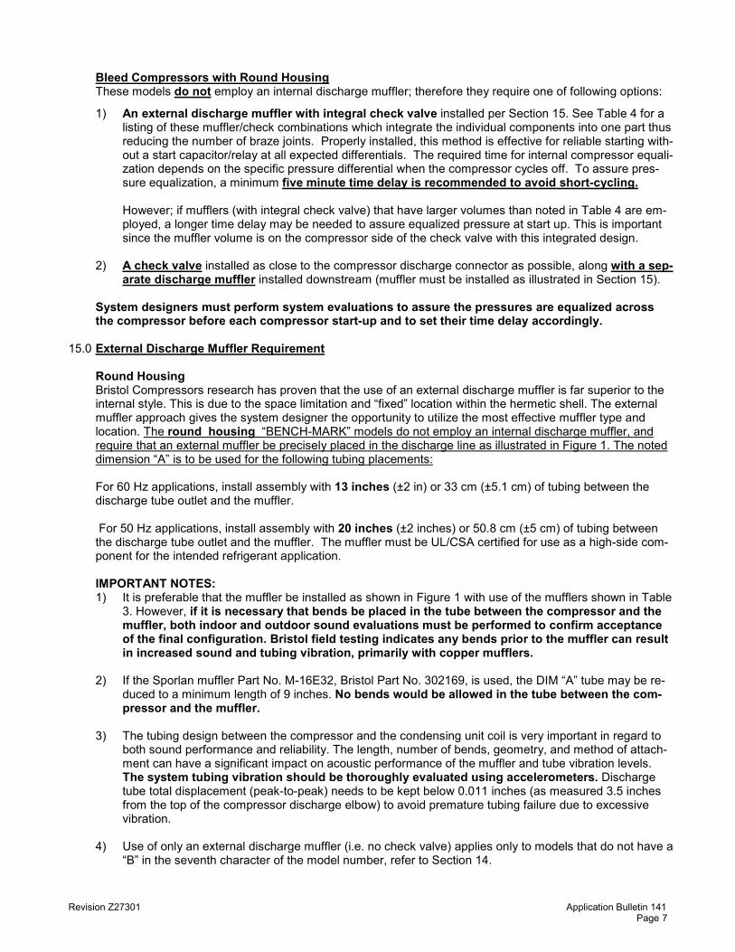
Bleed Compressors with Round Housing These models do not employ an internal discharge muffler; therefore they require one of following options:
1) An external discharge muffler with integral check valve installed per Section 15. See Table 4 for a listing of these muffler/check combinations which integrate the individual components into one part thus reducing the number of braze joints. Properly installed, this method is effective for reliable starting with-out a start capacitor/relay at all expected differentials. The required time for internal compressor equali-zation depends on the specific pressure differential when the compressor cycles off. To assure pres-sure equalization, a minimum five minute time delay is recommended to avoid short-cycling.
However; if mufflers (with integral check valve) that have larger volumes than noted in Table 4 are em-
ployed, a longer time delay may be needed to assure equalized pressure at start up. This is important since the muffler volume is on the compressor side of the check valve with this integrated design.
2) A check valve installed as close to the compressor discharge connector as possible, along with a sep-
arate discharge muffler installed downstream (muffler must be installed as illustrated in Section 15). System designers must perform system evaluations to assure the pressures are equalized across
the compressor before each compressor start-up and to set their time delay accordingly. 15.0 External Discharge Muffler Requirement Round Housing Bristol Compressors research has proven that the use of an external discharge muffler is far superior to the
internal style. This is due to the space limitation and “fixed” location within the hermetic shell. The external muffler approach gives the system designer the opportunity to utilize the most effective muffler type and location. The round housing “BENCH-MARK” models do not employ an internal discharge muffler, and require that an external muffler be precisely placed in the discharge line as illustrated in Figure 1. The noted dimension “A” is to be used for the following tubing placements:
For 60 Hz applications, install assembly with 13 inches (±2 in) or 33 cm (±5.1 cm) of tubing between the
discharge tube outlet and the muffler. For 50 Hz applications, install assembly with 20 inches (±2 inches) or 50.8 cm (±5 cm) of tubing between
the discharge tube outlet and the muffler. The muffler must be UL/CSA certified for use as a high-side com-ponent for the intended refrigerant application.
IMPORTANT NOTES: 1) It is preferable that the muffler be installed as shown in Figure 1 with use of the mufflers shown in Table
3. However, if it is necessary that bends be placed in the tube between the compressor and the muffler, both indoor and outdoor sound evaluations must be performed to confirm acceptance of the final configuration. Bristol field testing indicates any bends prior to the muffler can result in increased sound and tubing vibration, primarily with copper mufflers.
2) If the Sporlan muffler Part No. M-16E32, Bristol Part No. 302169, is used, the DIM “A” tube may be re-
duced to a minimum length of 9 inches. No bends would be allowed in the tube between the com-pressor and the muffler.
3) The tubing design between the compressor and the condensing unit coil is very important in regard to
both sound performance and reliability. The length, number of bends, geometry, and method of attach-ment can have a significant impact on acoustic performance of the muffler and tube vibration levels. The system tubing vibration should be thoroughly evaluated using accelerometers. Discharge tube total displacement (peak-to-peak) needs to be kept below 0.011 inches (as measured 3.5 inches from the top of the compressor discharge elbow) to avoid premature tubing failure due to excessive vibration.
4) Use of only an external discharge muffler (i.e. no check valve) applies only to models that do not have a
“B” in the seventh character of the model number, refer to Section 14.

Revision Z27301 Application Bulletin 141 Page 8
Oval Housing The oval housing models do not require an external discharge muffler for 60 Hz. The oval housing models do require an external discharge muffler for 50 Hz. The muffler should be installed
with 6 inches (±1 inches) of tubing between the discharge tube outlet and the muffler
FIGURE 1
Discharge Muffler or Muffler/
Check Valve
DIM “A”

Revision Z27301 Application Bulletin 141 Page 9
The Table 3 generic muffler recommendations are based on Bristol sound test evaluations with various systems. The Sporlan M-16E32 yielded the best overall field results. Operational characteristics can vary between different system types and applications. The OEM system designer must perform sound tests to determine the best muffler configuration and optimize its location in the discharge line to satisfy their particular design requirements. All available options should be thoroughly evaluated and the following considered:
• A heat sink is required to prevent internal check valve damage during brazing
• Do not use ball type check valve
• A filter-drier in the discharge line may be substituted for the external muffler, if system testing confirms that the filter-drier provides acceptable discharge pulse and sound attenuation.
• If components other than those recommended in Tables 2, 3 and 4 are utilized, Bristol advises the use of a high quality, non-positional check valve designed for near-zero leak rates. The muffler and check valve must be UL/CSA certified for use as high side components for the intended refrigerant application.
• Increased internal free volume or multi-chamber style discharge mufflers may provide superior results.
H82J Series Compressor Applications with Refrigerant R410A
PRODUCT GUIDE FOR TABLE 3
Application Cooling Only Heat Pumps
Voltage Frequency
60 Hz 50 Hz 60 Hz 50 Hz
Muffler* Tube Length*
Dim - “A” Muffler*
Tube Length* Dim - “A”
Muffler* Tube Length*
Dim - “A” Muffler*
Tube Length* Dim - “A”
Round Compressor Housing
A 13” ± 2” B 20” ± 2” C 13” ± 2” C 20” ± 2”
Oval Compressor Housing
External Muffler Not Required
A External Muffler Not Required
A 6” ± 1” 6” ± 1”
Note: Use above letter designation in choosing muffler below. *See Section 15.0 for further details on muffler and tube length.
TABLE 3
EXTERNAL MUFFLER ONLY
Product Guide Letter
Bristol Part
Number Manufacturer Material
Manufacturer Part
Number
Muffler OD (inch/cm)
Length (inch/cm)
Inlet and Outlet ID (inch/cm)
Internal Free Volume
(inches3/cc)
A 302140 Parker Copper 031780-00 1.6 / 4.1 4.4 / 11.1 .50 / 1.3 5.4 / 88.5
A 302164 Kraftube Steel EM-20-2.605-000 2.1 / 5.4 4.9 / 12.4 .50 / 1.3 9.9 / 162.2
B 302146 Parker Copper 058750-00 2.0 / 5.1 6.5 / 16.5 .50 / 1.3 13.3 / 218.0
B 302165 Kraftube Steel EM-20-4.725-00-0 2.1 / 5.4 7.0 / 17.8 .50 / 1.3 15.8 / 258.9
C 302169 Sporlan Steel M-164-S or M-16E32
3.0 / 7.6 6.0 / 15.0 .50 / 1.3 24 / 393.0
C 302167 Kraftube Steel EM-30-4.250-00-0 3.1 / 7.9 6.5 / 16.5 .50 / 1.3 35 / 573.5
Note: Direct muffler orders to manufacturers should reference the manufacturer’s part number.

Revision Z27301 Application Bulletin 141 Page 10
TABLE 4
EXTERNAL MUFFLER WITH INTEGRAL CHECK VALVE (for use only with round housing compressors with bleed)
Bristol Part Number
Manufacturer Material Manufacturer
Part Number
Muffler OD (inch/cm)
Length (inch/cm)
Inlet and Outlet ID (inch/cm)
Internal Free Volume
(inches3/cc)
250577 Superior Copper 900RGN-8S 1.63 / 4.14 7.88 / 20.0 .50 / 1.3 9.7 / 159
250578 Mueller Copper A-18051 1.63 / 4.14 7.88 / 20.0 .50 / 1.3 9.6 / 157
250576 Henry
Technologies Copper MSM-11 1.63 / 4.14 7.88 / 20.0 .50 / 1.3 9.9 / 162
16.0 Operation Envelope “BENCHMARK” compressors are designed to operate within a specific range of operation or envelope.
Systems must be designed so that the compressor does not operate outside the envelope or continuously at its boundary. Reference the individual compressor model specification sheet for the operational envelope, which is available at www.bristolcompressors.com or may be obtained directly from Bristol Compressors. Any deviation from the published limits must be evaluated and approved by Bristol Compressors.
17.0 Mounting Isolators Although the “BENCHMARK” model compressors are internally isolated and the vibrations transmitted to the
shell are exceptionally low, external mounting isolators (grommets) are required. These resilient type mounts have been specially developed to isolate the compressor from the system chassis and increase reli-ability. Refer to Application Bulletin 112 for guidance on selection of isolators.
Customers preferring alternative mounting isolator designs should thoroughly test to ensure satisfactory per-
formance. 18.0 Field Replacement The “BENCHMARK” model compressors are excellent choices for field replacements and efficiency up-
grades. The larger capacity models are specifically designed with the external discharge muffler concept to achieve exceptionally quiet operation while maintaining high efficiency. When used as a replacement for compressor models in systems not equipped with an external discharge muffler, the proper external dis-charge muffler and mounting components should be supplied with the compressor and accompanied with detailed installation instructions.

Revision Z27301 Application Bulletin 141 Page 11

Revision Z27301 Application Bulletin 141 Page 12
Recommended sources for check valves, mufflers, and muffler/check combinations:
Henry Technologies 701 S. Main Street Chatham, IL 62629 (217) 483-2406 www.henrytech.com
Mueller Refrigeration Company, Inc. 121 Rogers Street Hartsville, TN 37074 (800) 251-8983 [email protected]
MUFFLER ONLY
Parker Hannifin 17325 Euclid Avenue Cleveland, OH 44112 (800) 272-7537 www.parker.com
Sporlan Valve Company 206 Lang Drive Washington, MO 63090-1040 (636) 239-1111 www.sporlan.com
Kraftube 925 E. Church Avenue Reedy City, MI 49677 (231) 832-5562, Extension 110 www.kraftube.com
MUFFLER + CHECK VALVE COMBINATION
Mueller Refrigeration Company, Inc. 121 Rogers Street Hartsville, TN 37074 (800) 251-8983 [email protected]
Superior Sherwood Valves 2111 Liberty Drive Niagara Falls, NY 14304-3744 (716) 505-4800 www.sherwoodvalves.com
Henry Technologies 701 S. Main Street Chatham, IL 62629 (217) 483-2406 www.henrytech.com
CHECK VALVE ONLY

Revision Z27301 Application Bulletin 141 Page 13
REVISIONS
S33603 1/23/09 U15902 7/30/10
V29902 1/3/12 X30201 4/29/14
Z27301 10/2/15
Release EN Number M28001 Release Date 3/11/04