hague and london oil plchaloil.co.uk/wp-content/uploads/2016/12/halo-pgk-shallow-gas... · hague...
TRANSCRIPT
Hague and London Oil Plc
Exploiting Shallow Gas Offshore Netherlands
November 2016
De-Gassing Shallow Hazards or De-Risking Shallow Gas
2
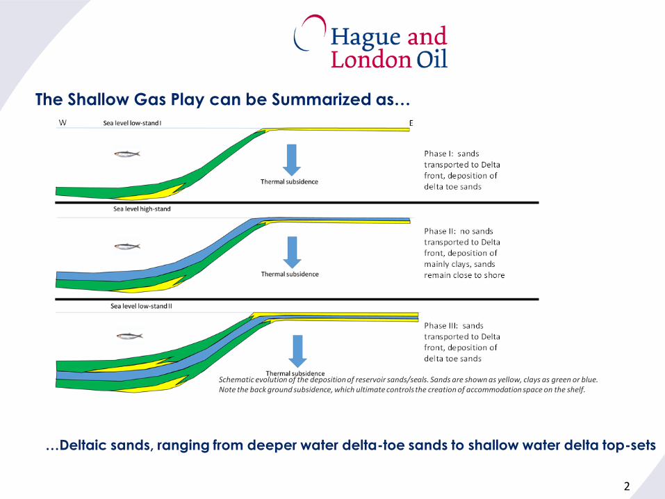
Schematic evolution of the deposition of reservoir sands/seals. Sands are shown as yellow, clays as green or blue. Note the back ground subsidence, which ultimate controls the creation of accommodation space on the shelf.
The Shallow Gas Play can be Summarized as…
…Deltaic sands, ranging from deeper water delta-toe sands to shallow water delta top-sets
3
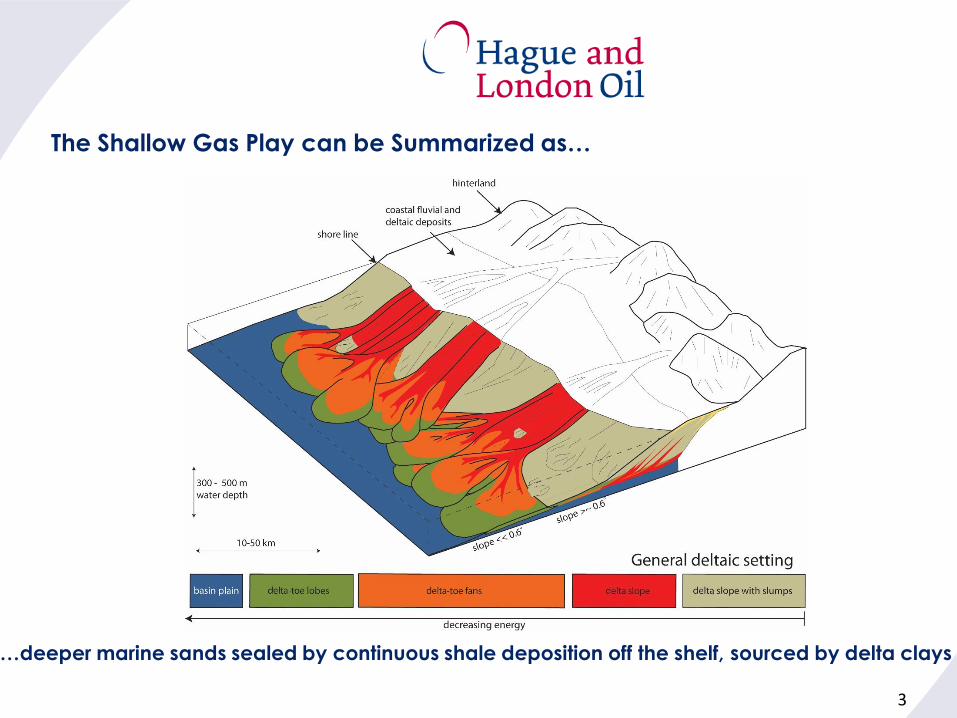
The Shallow Gas Play can be Summarized as…
…deeper marine sands sealed by continuous shale deposition off the shelf, sourced by delta clays
4
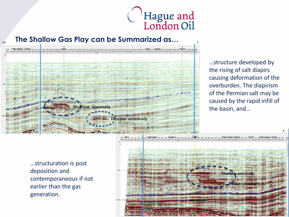
Shallow anomaly
Deeper anomaly
W EBlock F4
…structure developed by the rising of salt diapirscausing deformation of the overburden. The diapirismof the Permian salt may be caused by the rapid infill of the basin, and…
The Shallow Gas Play can be Summarized as…
…structuration is post deposition and contemporaneous if not earlier than the gas generation.
5
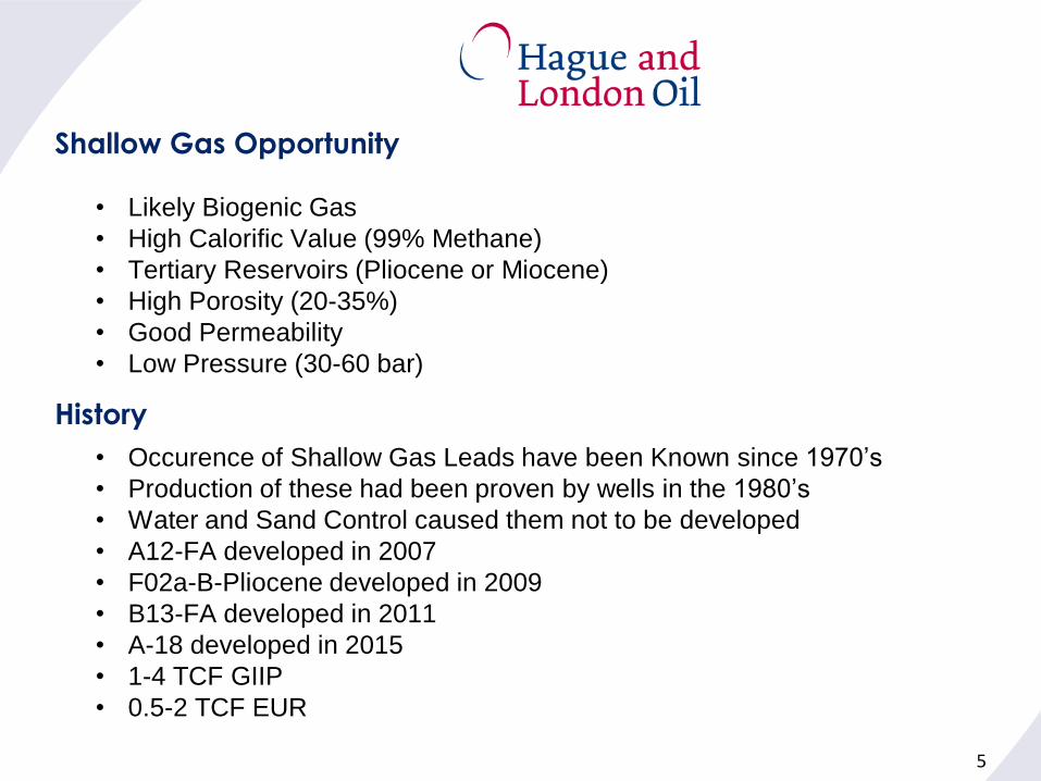
Shallow Gas Opportunity
• Likely Biogenic Gas
• High Calorific Value (99% Methane)
• Tertiary Reservoirs (Pliocene or Miocene)
• High Porosity (20-35%)
• Good Permeability
• Low Pressure (30-60 bar)
• Occurence of Shallow Gas Leads have been Known since 1970’s
• Production of these had been proven by wells in the 1980’s
• Water and Sand Control caused them not to be developed
• A12-FA developed in 2007
• F02a-B-Pliocene developed in 2009
• B13-FA developed in 2011
• A-18 developed in 2015
• 1-4 TCF GIIP
• 0.5-2 TCF EUR
History

6
Challenges
• Thinly Stacked Reservoirs
• Poorly Consolidated Sands
• Shallow
• Low Relief
• Low Pressure
Solutions
• Horizontal Wells
• Expandable Screens
• Hi-Res Seismic
• Compression
A12 Central Processing Platform with Compression FacilitiesExpandable Screen in Horizontal Well
7
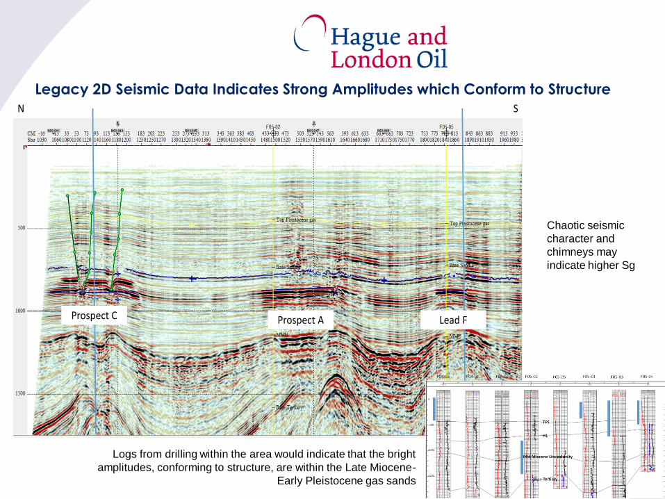
N SBlock F5
Prospect AProspect C Lead F
Legacy 2D Seismic Data Indicates Strong Amplitudes which Conform to Structure
Logs from drilling within the area would indicate that the bright
amplitudes, conforming to structure, are within the Late Miocene-
Early Pleistocene gas sands
Chaotic seismic
character and
chimneys may
indicate higher Sg
8
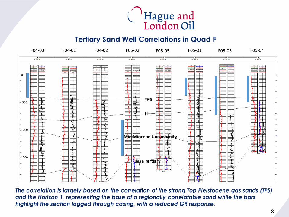
F04-03 F04-01 F04-02 F05-02 F05-05 F05-01 F05-03 F05-04
TPS
H1
Mid Miocene Unconfrmity
Base Tertiary
500
1000
1500
0
The correlation is largely based on the correlation of the strong Top Pleistocene gas sands (TPS)
and the Horizon 1, representing the base of a regionally correlatable sand while the bars
highlight the section logged through casing, with a reduced GR response.
Tertiary Sand Well Correlations in Quad F
9
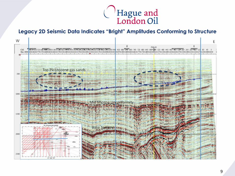
Legacy 2D Seismic Data Indicates “Bright” Amplitudes Conforming to Structure
10
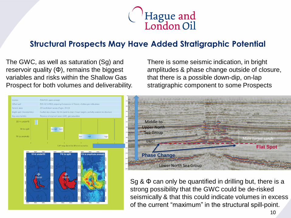
Structural Prospects May Have Added Stratigraphic Potential
There is some seismic indication, in bright
amplitudes & phase change outside of closure,
that there is a possible down-dip, on-lap
stratigraphic component to some Prospects
The GWC, as well as saturation (Sg) and
reservoir quality (Φ), remains the biggest
variables and risks within the Shallow Gas
Prospect for both volumes and deliverability.
Sg & Φ can only be quantified in drilling but, there is a
strong possibility that the GWC could be de-risked
seismically & that this could indicate volumes in excess
of the current “maximum” in the structural spill-point.
Flat Spot
Phase Change
11
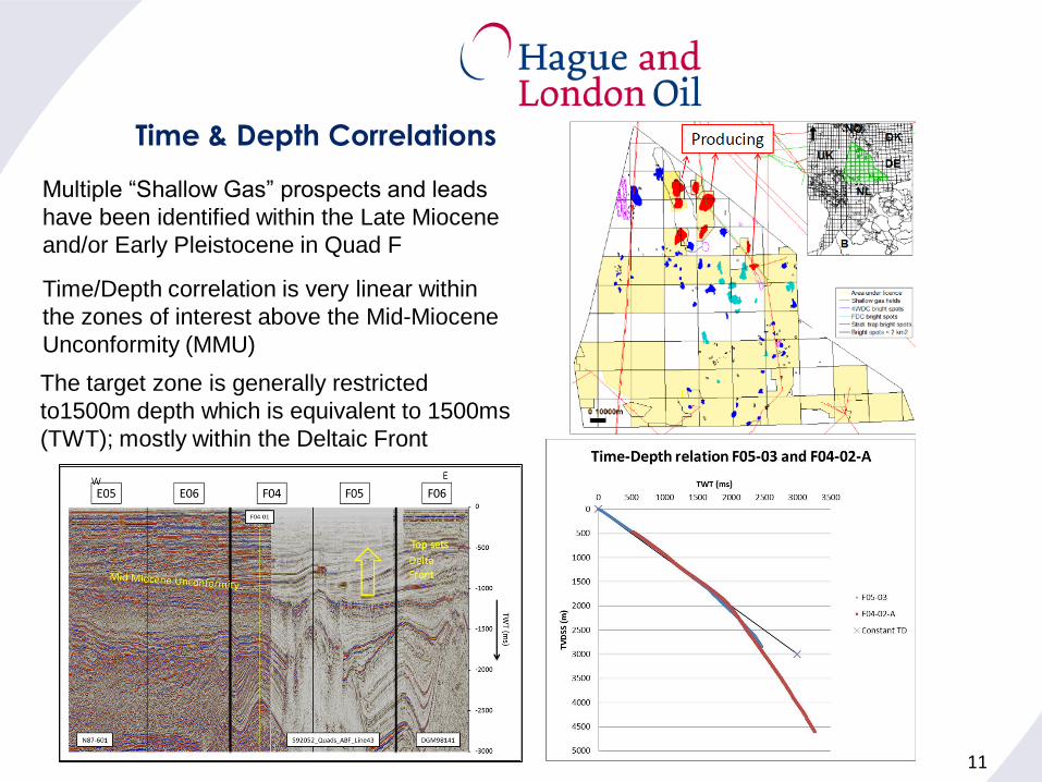
Time/Depth correlation is very linear within
the zones of interest above the Mid-Miocene
Unconformity (MMU)
Time & Depth Correlations
Multiple “Shallow Gas” prospects and leads
have been identified within the Late Miocene
and/or Early Pleistocene in Quad F
The target zone is generally restricted
to1500m depth which is equivalent to 1500ms
(TWT); mostly within the Deltaic Front
12
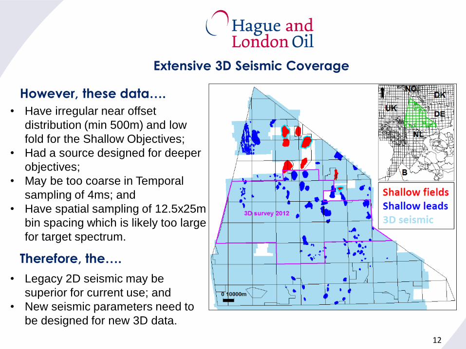
• Have irregular near offset
distribution (min 500m) and low
fold for the Shallow Objectives;
• Had a source designed for deeper
objectives;
• May be too coarse in Temporal
sampling of 4ms; and
• Have spatial sampling of 12.5x25m
bin spacing which is likely too large
for target spectrum.
• Legacy 2D seismic may be
superior for current use; and
• New seismic parameters need to
be designed for new 3D data.
Extensive 3D Seismic Coverage
However, these data….
Therefore, the….
13
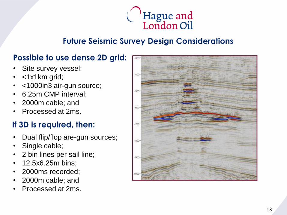
• Site survey vessel;
• <1x1km grid;
• <1000in3 air-gun source;
• 6.25m CMP interval;
• 2000m cable; and
• Processed at 2ms.
• Dual flip/flop are-gun sources;
• Single cable;
• 2 bin lines per sail line;
• 12.5x6.25m bins;
• 2000ms recorded;
• 2000m cable; and
• Processed at 2ms.
Future Seismic Survey Design Considerations
Possible to use dense 2D grid:
If 3D is required, then:
14
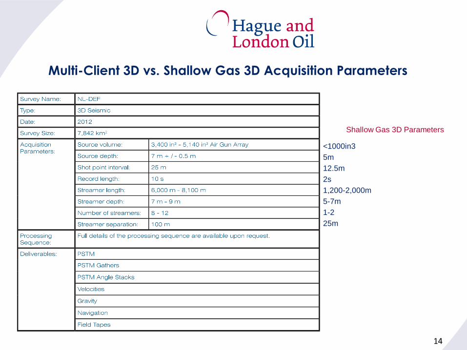
Multi-Client 3D vs. Shallow Gas 3D Acquisition Parameters
<1000in3
5m
12.5m
2s
1,200-2,000m
5-7m
1-2
25m
Shallow Gas 3D Parameters
15
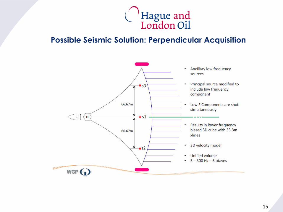
Possible Seismic Solution: Perpendicular Acquisition
16
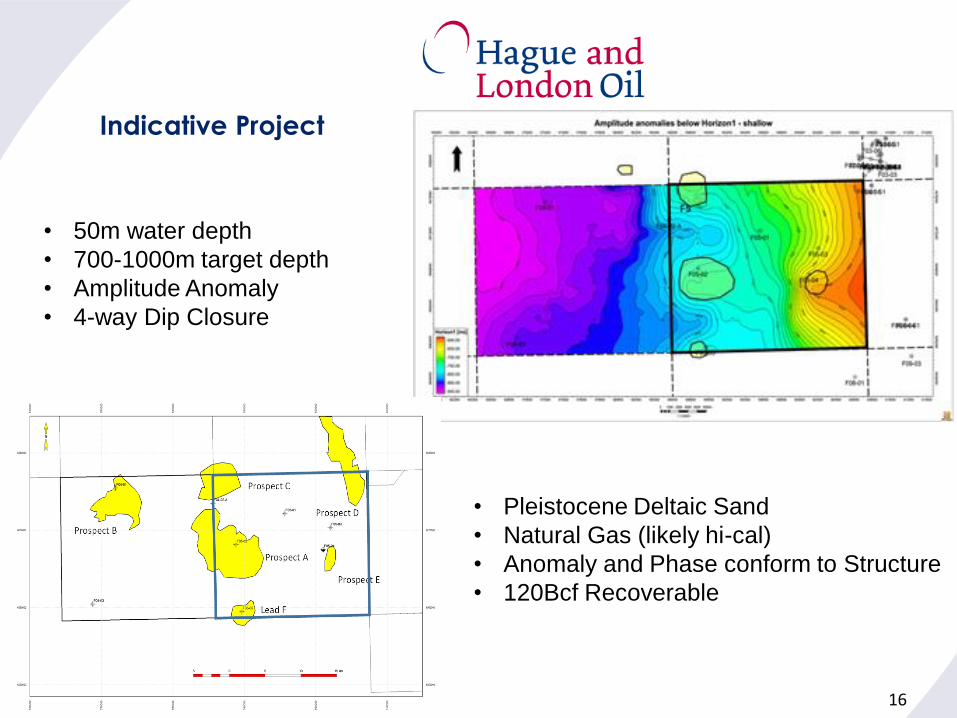
• 50m water depth
• 700-1000m target depth
• Amplitude Anomaly
• 4-way Dip Closure
Indicative Project
• Pleistocene Deltaic Sand
• Natural Gas (likely hi-cal)
• Anomaly and Phase conform to Structure
• 120Bcf Recoverable
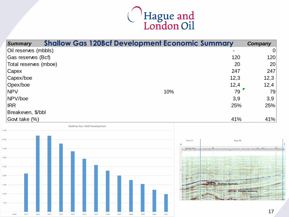
Summary Company
Oil reserves (mbbls) - 0
Gas reserves (Bcf) 120 120
Total reserves (mboe) 20 20
Capex 247 247
Capex/boe 12,3 12,3
Opex/boe 12,4 12,4
NPV 10% 79 79
NPV/boe 3,9 3,9
IRR 25% 25%
Breakeven, $/bbl
Govt take (%) 41% 41%
17
Shallow Gas 120Bcf Development Economic Summary
18
Shallow Gas Summary
• Proven Hydrocarbon Resource
• Proven Development Technology (Expandable Screens)
• Availability of Acreage
• Extensive Existing Seismic Coverage
• Amplitudes Lead and Sesimic Character Lead Exploration
• Key Risks:
• Gas Saturation
• Reservoir Quality
• New Seismic Data Would be Cost-Effective
• Improved Reservoir Characterizaton through New “Tuned” Seismic
• Stratigraphic Component Could lead to much larger Structural Leads
• Favorable Economics (i.e. Small Fields Policy)
• Access to Infrastructure (i.e. NOGAT, etc)
• “Hub and Spoke” Development Concept: CPP & Satellites
• Delays Abandonment by Years for Ageing Infratstructure
19
Thank You to:
• EBN
• TNO
• Petrogas
• WGP
• Spectrum
• PGK