hal hardware access library - cernajbell.web.cern.ch/ajbell/documents/vme/halusersguide.pdf · hal...
TRANSCRIPT

HAL
Hardware Access LibraryUser's and programmer's Guide
Document Version : 03-02
Created : 24. January 2006
Last updated: : 25. January 2006
HAL version : ver-03-11
URL : http://cmsdoc.cern.ch/~cschwick/software/documentation/HAL
Author : Christoph Schwick

ii

Table of Contents
1 Purpose of the Hardware Access Library.....................................................................1
2 The components of the library and their collaboration.................................................3
3 Installation....................................................................................................................43.1 Directory structure................................................................................................53.2 Installing HAL......................................................................................................6
4 User's Guide..................................................................................................................94.1 The basic functionalities ......................................................................................9
4.1.1 The AddressTable .........................................................................................94.1.1.1 VME - ASCII AddressTable Format ..................................................104.1.1.2 PCI - ASCII Address Table Format.....................................................124.1.1.3 VME-XML AddressTable format ......................................................134.1.1.4 VME64x-XML AddressTable format ................................................134.1.1.5 PCI-XML AddressTable format..........................................................14
4.1.2 The BusAdapter ..........................................................................................154.1.3 The Hardware Devices for VME or PCI.....................................................16
4.1.3.1 The VME64xDevice............................................................................184.2 Complete Example Program...............................................................................224.3 The sequencer .....................................................................................................24
4.3.1 Commands of the Sequencer ......................................................................244.3.2 Example Program .......................................................................................26
4.4 Examples in the distribution ..............................................................................284.4.1 The TTCviConsole example ......................................................................284.4.2 The XMLAddressTableTester example .....................................................284.4.3 The PerformanceTester ..............................................................................294.4.4 The XDAQ application "Trigger" ..............................................................29
4.5 VME64x Plug And Play Support .......................................................................294.5.1 Steps during the VME64x Plug and Play configuration. ...........................304.5.2 Implementation details ...............................................................................31
5 BusAdapters and Device Drivers................................................................................325.1 What are Bus Adapters? .....................................................................................325.2 BusAdapters contained in the library .................................................................32
6 Write your own extensions.........................................................................................346.1 The BusAdapter .................................................................................................34
6.1.1 PCI BusAdapters ........................................................................................346.1.2 VME BusAdapters .....................................................................................35
6.2 The AddressTableReader ...................................................................................376.3 The CommandSequenceReader .........................................................................37
iii

List of TablesTable 4.1 : Elements of the AddressTable and their meaing..........................................10Table 4.2 : Example for a VME AddressTable in ASCII format...................................10Table 4.3 : Example for a VME64x AddressTable in ASCII format.............................11Table 4.4 : Example of a PCI AddressTable in ASCII format.......................................12Table 4.5 : Example for an XML VME AdddressTable.................................................13Table 4.6 : Example of a VME64x AddressTable..........................................................14Table 4.7 : Example of an XML PCI AddressTable.......................................................15Table 4.8 : List of the possible operations on a HardwareDevice..................................17Table 4.9 : Names of the Configuration space items predefined by the VME64xstandard. These items are contained in a hardcoded AddressTable (classVMEConfigurationSpaceAddressReader)......................................................................21Table 4.10 : A simple header file for a PCI card............................................................22Table 4.11 : The listing of the implementatinon file G3RuiCard.cc..............................23Table 4.12 : Listing of the main program G3Tester.cc...................................................23Table 4.13 : List of commands supported by the sequencer...........................................25Table 4.14 : A small test program which works with Sequences...................................27Table 4.15 : An example of a Sequence. .......................................................................27Table 6.1 : Functions which must be implemented by a PCI BusAdapter....................35Table 6.2 : Functions which must be implemnted by a VMEBusAdapter.....................36
iv

Purpose of the Hardware Access Library
1 Purpose of the Hardware AccessLibrary
The Hardware Access Library (HAL) has been developed for the online environment ofthe CMS experiment at LHC.
In order to design and build a hardware module which is controlled by a computer, a lotof time is spent to develop the necessary software. Especially in the debugging phase ofthe module the software is continuously changed and updated. At the same time FPGAsare reprogrammed and the address table of the module changes. This procedure isrelatively time consuming since it involves repetitive changes of the source code withre-compilation (and debugging) cycles.
In addition software is often developed on a hardware setup which is not the final one.The controller might change (VME board processors might be exchanged with PCI-to-VME interfaces). The used operating system might change (VxWorks on a VMEController, Linux in a PC). It also happens that the technology of the bus system will bechanged during the development phase of a module (whereas the first prototypes havebeen VME-modules the final module might be implemented as a PCI board).
The purpose of this library is to make the above mentioned steps as painless as possibleby providing a set of flexible tools which allow to change a large part of the surroundinghardware and software architecture of the module with only minimal changes in thealready developed code. The library has been designed in order to allow the user toreuse the already written code in all the scenarios mentioned above.
The library has been designed to be as user-friendly as possible. For example theconfiguration (which is a set of parameters written to a set of registers in the module)might be changed without necessarily re-compiling the code. If the controller of a VMEcrate is changed, only two lines in the user software have to be changed. The API wasdesigned in a way that it should be possible for a non-expert to read and understandprograms written with his library without the necessity to study this manual in detail.(Software authors instead need to read this manual and need to consult the html-APIdocumentation coming with the library.)
The library is also useful if working with commercial hardware modules. These oftenrequire complicated configuration and setup procedures. The library allows to changethese procedures without re-compiling the software.
The user interface is kept simple and only indispensable functionality has been built intothe library. This reduces the learning phase and makes programming of the hardwareeasy without studying thick manuals. The philosophy is that it will be implemented wasis needed and not what might be useful. Additional features will be implemented on
1

Purpose of the Hardware Access Library
request of the users.
Currently the library supports VME, VME64x (support for that part of the specification,which allows plug and play configuration of a VME64x-crate, and support ofconfiguration space access) and PCI. For VME64x some services are provided whichallow plug and play configuration of VME64x crates. Crate configurations with amixture of standard VME and VME64x modules are supported.
The supported platform is currently only Linux since this is the only platform used inCMS1.
It should be easy to extend the library at those points where it interfaces to the outsideprogramming environment. For example it should be easy to write adapter classes to not“officially” supported drivers, or to develop readers of AddressTables for not supportedmedia.
1 The support for VxWorks which has been present in previous versions of the library has beendiscontinued since it is not used any more in CMS. In case of necessity the library can be portedeasily to another operating system. So far only the StopWatch class in the generic part of the library islinux specific and would have to be adapted to other operating systems.
2

The components of the library and their collaboration
2 The components of the library andtheir collaboration
Figure 1 shows the main components of the HAL and how they interact with the userprogram. The user program uses an implementation of the HardwareDeviceInterfaceclass (in the following called the “HardwareDevice”) to perform read- and write-commands on the hardware module. The HardwareDevice in turn needs to communicatewith the hardware through a driver. The interface between the HardwareDevice and thedriver is the “BusAdapter”.
Hardware modules are accessed issuing read and write commands to specific addressesin the module. Different addresses correspond to different registers or functions of themodule. Moreover single bits or bit-fields within a register can have specific meanings.The designer of the module defines the meanings of the different addresses and bit-fields in the address table of the module by forming so called “items”. The hardwareaccess library uses the address tables in order to access single items in the hardware.The association of the addresses and the bit fields to logical items is done in theAddressTable class which is read by a HardwareDevice Object before operation. In thisway it is possible to change the address table of a module without the need to recompilethe source code of the user program. In addition the source code becomes readable sinceno addresses appear in the code but only strings which identify the various logical items.
Procedures to configure a device for a specific operational mode can be stored in“sequences”. The Sequencer class can be used to read in such sequences and to executethem from the user program. Sequences can be changed without the need of recompilingthe user code. The sequencer contains limited functionality to parametrize thesequences. For example it is possible that some address is passed to the sequence andsubsequent commands of the sequence can be written to be relative to this address.
A set of classes is provided in order to automatically configure VME64x cratescontaining modules which allow for address relocation as specified by VME64x. Thememory map of the crate is automatically created and the base addresses are set for allVME64x modules. The user is provided with VME64xDevice objects representing themodules found in the crate. In order to map the crate and construct the VME64xDevicesthe serial number is read out of each module and used as a key to obtain thecorresponding AddressTable. Currently an ASCII file contains map which associates theserial numbers with a VME module “type”. A second ASCII file contains the mappingwhich associates an AddressTable to each module typel In future these mappings areexpected to come from a database. As soon as there will be support for database accessin the CMS online software, the HAL will contain classes to provide these mappings viaa database.
3

Installation
3 Installation
4
Figure 1 : Functional blocks of the HAL. The arrows represet information exchange. A dashedarrow indicates an optional information flow. The relations between the classes are discussedin detail in the following chapters.
User Program
Sequence(optional)
Reader
AddressTable
ReaderVME64x
Crate
Reader
HardwareDevice
BusAdapter(PCI / VME)
Device Driver
Hardware module
HALLibrary

Installation
3.1 Directory structureThe HAL consists of several libraries. There is one core library and some optionallibraries which depend on the specific environment of the user. The code for the variouslibraries is organized in a subdirectory structure equivalent to that of XDAQ: includefiles are contained in the subdirectory {package}/include or package/include/{arch}.Implementation code is in {package}/src/common or {package}/src/{arch} whereas thelibrary is built in the subdirectory {package}/src/{arch}/{BSP}. {package} stands forthe component of the HAL. Since currently only linux on a PC is supported {arch}stands for linux and {bsp} for x86. You might find sometimes a subdirectory{package}/classtesters. This contains code for testing some of the components of theHAL during development. If you are curious you can look into the files. They are notfurther documented though.
After uncompressing the distribution of the HAL library in the main directory called“hal” you find the following set of subdirectories:
• makeDefinitions contains files which are included by the various Makefilesof the HAL. They contain the general rules how to compile and link thelibraries and applications.
• lib contains all the libraries after you have finished the installationprocedure. There will be one library containing the system independent corecode of the HAL. In addition for each BusAdapter one library will beavailable.
• generic contains the platform independent core-code of the hal-library. Thispart forms the core of the HAL.
• busAdapter contains all the busAdapters included in the package. EverybusAdapter is compiled into its own library. So it is easy for the user tochoose which BusAdapter to build. This is important because he will not beable to build a BusAdapter for a driver of which he does not have theresources. (The include files and the libraries of the drivers are of coursenecessary in order to use the driver.)
• XDAQTools is an obsolete directory!It contains the implementation of a set of interfaces defined in the genericpart of the HAL, which are used during the configuration of a VME64xcrate. This implementation worked with the now obsolete XDAQ Datastore,which was an database interface prototype. As soon as the new version ofXDAQ database access package will be available, a new version of thislibrary will be provided. Currently the XDAQTools package is not compiledduring the build procedure of the HAL.
5

Installation
• examples contains some test applications which a user can try out in order toget started with HAL. The applications are all written to useDummyBusAdapters so that they can be tried out without real hardwareconnected to the computer. The subdirectory XDAQ contains exampleswhich only work in an XDAQ environment. They show how to use the HALin a XDAQ application. The Makefile is may be the most interesting part ofthese examples.
• utilities contains a small library with useful classes which can be reused bythe user. The HAL does work without these classes. Some are used in theexamples and some are used during development and testing.
• tools contains scripts or small utilities which ease the usage of the HAL.Two perl scripts for VME and PCI are provided which convert an ASCIIaddress table to its XML representation. The input can be a file used by theVME(PCI)AddressTableASCIIFileReader or can be the output of the print()method of the AddressTable.
• doc contains a html-file with links to the API documentation and to a localcopy of this manual. If the links API documentation do not work the usermust create the local API documentation by invoking the correspondingtargets of the main Makefile.
• halwish contains classes to extend a TCL/Tk installation with newcommands to integrate the hal. Only the read and the write command of theHAL-API are implemented. The implementation is a “quick hack” and notfurther documented. Somebody with some expertise in TCL/Tk might find ituseful, and therefore it is left in the distribution. The CMS online softwareshould not contain any code using this TCL/Tk interface. This packagemight dissapear in future!
• xcept contains a copy of the XDAQ exception library. This copy in onlycompiled and used inc ase the hal is used stand-alone (i.e. not in an CMSonline environment). In standard CMS online environments the xcept libraryof the XDAQ installation is used.
3.2 Installing HALIf you are working in a XDAQ environment (this is the recommended way of workingwith the HAL) you should install the HAL into the subdirectory TriDAS/daq/hal (thismeans you should untar the distribution in the directory TriDAS/daq with the commandgtar xzvf halPackage.tgz). Afterwards you go into the hal subdirectory to proceed withthe installation.
If you are doing a stand-alone installation of the HAL choose a directory at your will,un-compress the package and go in the hal subdirectory.
6

Installation
The installation of the HAL library is prepared by the configure.pl script in the rootdirectory.
• The script tries to find out if your are working in a standard CMS onlineenvironment or if you want to do a stand-alone installation. For this it checksif the environment variable XDAQ_ROOT is pointing to an existingdirectory. (This variable must point to the TriDAS directory of an XDAQinstallation). Be sure to have this environmne tvariable set (or unset) beforeyou run the configure.pl script.
• In a second step the script tries to determine, which BusAdapters have to becompiled. This is done by looking if the corresponding hardware drivers areinstalled at their default locations. In particular the following checks areperfomed:
– If the directory /usr/local/SBS/1003/v* is found it is assumed to containa valid installation of the SBS VME bridge driver and thecorresponding BusAdapter will be compiled.
– If the directory /usr/local/CAEN CAEN-VME/Linux exists and if thelink /usr/lib/libCAENVME.so exists and links to a library which has asufficiently high version number (depending on the HAL version) thenthe corresponding BusAdapter will be compiled.
– If the directory$XDAQ_ROOT/daq/itools/packages/generic_pci_access and thedirectory $XDAQ_ROOT/daq/itools/packages/xdaq-shell exist then theBusAdapter for accessing PCI modules plugged into the PC will becompiled.
Important Note: It is obvious from the description above that the drivers must beinstalled before the configure script is launched. The configure.pl script only works ifthe drivers are installed at their default locations. In particular the PCIi386BusAdapter isonly compiled if the HAL is installed in an XDAQ environment. Also support for XMLaddresstable file format is only available if HAL is installed in an XDAQ environment(the Xerces package is taken from the XDAQ installation). If a setup different from thedefault is desired (e.g. a stand alone installation with XML support orPCIi386BusAdapter support) the file Makefile.in has to be edited by hand after theconfigure.pl has run.
To run the configure.pl script go into the directory “hal” and type:
perl ./configure.pl
To compile type:
gmake HAL
7

Installation
After this procedure all libraries are installed in hal/lib/. In order to compile theexamples type:
gmake examples
In order to run the examples type in the hal/examples/{example}/src/linux/x86directory:
runnit
Before you run an application using HAL you must make sure that the search path toyour libraries is pointing to the newly created libraries. (In case of the examples this isdone by the “runnit” script. Look into it.) You have to set the environment variableLD_LIBRARY_PATH to the directory {installdir}/hal/lib/linux/x86. Examplefor the bash shell:
export LD_LIBRARY_PATH=$LD_LIBRARY_PATH:/{installdir}/hal/lib/linux/x86
When you link your application you must make sure that the path to the libraries and thelibraries themselves are indicated to the linker.
In order to run the XDAQ examples you must know how to run an XDAQ application.Nothing special applies to an application using the HAL. A small README.txt file iscontained in the hal/example/XDAQ/Trigger directory. It explains what has to bechanged in order to run with a different BusAdapter. The application must be linkedagainst the relevant libraries of the HAL. How this is done can be seen in thecommented Makefile of the example.
In order to generate the API documentation locally (html format) you type:
gmake localDoc
The documentation is linked from “Documentation” paragraph of the main localdoumentation page:
file://{path-to your-hal-installation}/doc/index.html
(If you install the HAL from the stand-alone distribution on the HAL homepage thelocal API documentation is already created for you. If you install from the the DAQKitor from the the XDAQ-worksuite you need to create the local API documentation withthe steps oulined above.)
If you want to see all possible targets for the main Makefile (in the root directory) youcan type
gmake help
A list of all relevant targets is given. Of course it is always good to look into theMakefile in order to find out how it works. You might find some more targets which areusually not interesting for the user.
8

User's Guide
4 User's GuideThis section provides the necessary information in order to write applications whichaccess hardware modules via this library. First the basic functionalities are discussed. Inthe second part the usage of the sequencer is described. However, the programmershould always use the html-API-documentation of the library in order to get detailedinformation on the API of the library (this documentation is contained in the distributionof the library).
4.1 The basic functionalities In order to access hardware three objects must be created. An AddressTable which holdsthe mapping of logical items to addresses and bitmasks. A BusAdapter which interfacesto the device driver and finally an object representing the hardware module itself: theHardwareDevice (Either a PCIDevice a VMEDevice or a VME64xDevice). The detailsof these three classes are described in the following sections.
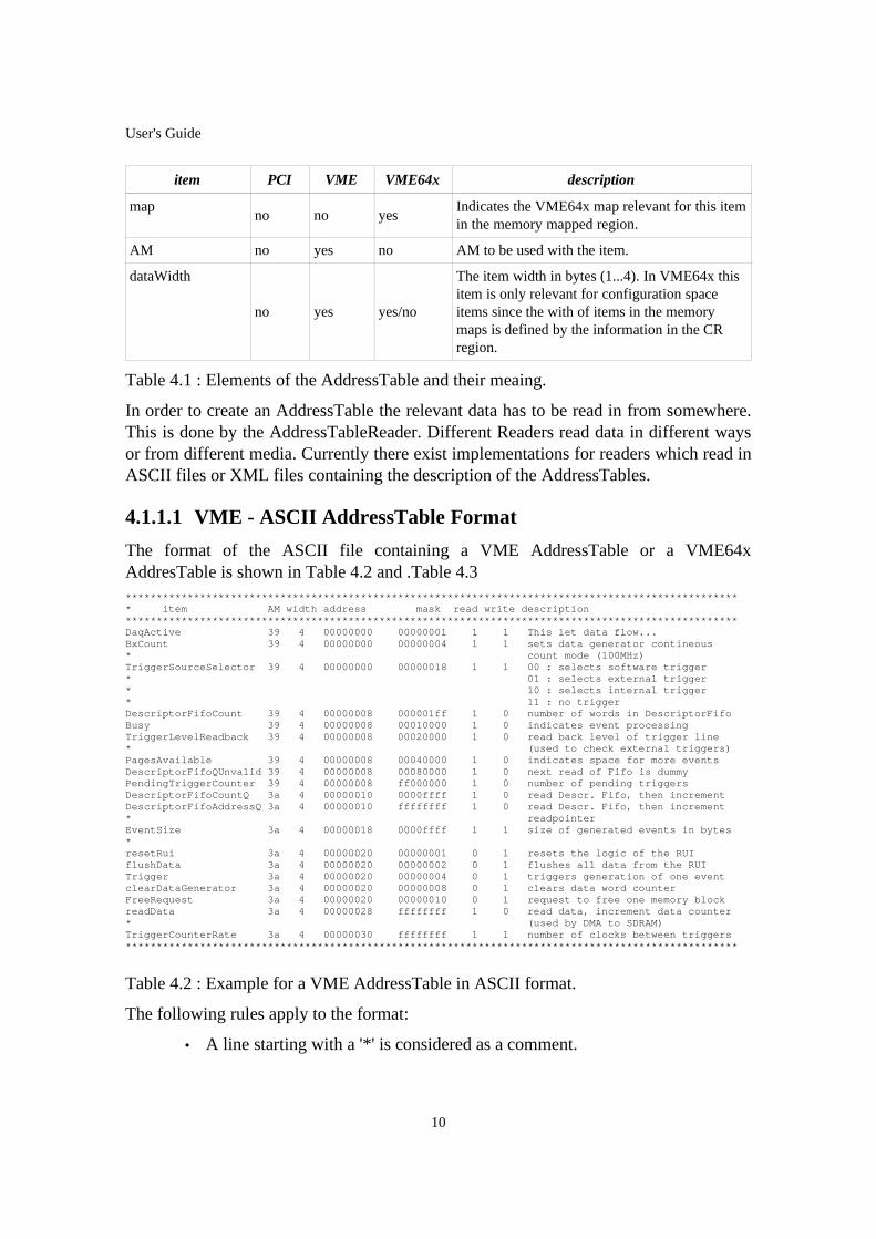
4.1.1 The AddressTable The AddressTable contains the information about the items which are accessible in thehardware and how they should be accessed. Some entries in the table depend on thetechnology of the hardware: PCI VME or VME64x. Table 4.1 summarizes all of theentries:
item PCI VME VME64x description
item yes yes yes Ab arbitrary name for the item to access.
address yes yes yes offset wrt the baseaddress relevant for this item.
maskyes yes yes
A bitmask defining the relevant bitfield for theitem.
readyes yes yes
'1': the item is readable.'0': the item is not readable.
writeyes yes yes
'1': the item is writable.
'0': the item is not writable.
description yes yes yes Optional documentation of the item.
accessMode
yes no yes
'memory' : the item is accessed in one of thememory mapped regions.
'configuration' : the item is in the configurationspace.
BARyes no no
Indicates the relevant BAR for items in memorymapped region. For configuration space itemsthis field MUST be left empty.
9
User's Guide
item PCI VME VME64x description
mapno no yes
Indicates the VME64x map relevant for this itemin the memory mapped region.
AM no yes no AM to be used with the item.
dataWidth
no yes yes/no
The item width in bytes (1...4). In VME64x thisitem is only relevant for configuration spaceitems since the with of items in the memorymaps is defined by the information in the CRregion.
Table 4.1 : Elements of the AddressTable and their meaing.
In order to create an AddressTable the relevant data has to be read in from somewhere.This is done by the AddressTableReader. Different Readers read data in different waysor from different media. Currently there exist implementations for readers which read inASCII files or XML files containing the description of the AddressTables.
4.1.1.1 VME - ASCII AddressTable Format
The format of the ASCII file containing a VME AddressTable or a VME64xAddresTable is shown in Table 4.2 and .Table 4.3*************************************************************************************************** * item AM width address mask read write description *************************************************************************************************** DaqActive 39 4 00000000 00000001 1 1 This let data flow... BxCount 39 4 00000000 00000004 1 1 sets data generator contineous * count mode (100MHz) TriggerSourceSelector 39 4 00000000 00000018 1 1 00 : selects software trigger * 01 : selects external trigger * 10 : selects internal trigger * 11 : no trigger DescriptorFifoCount 39 4 00000008 000001ff 1 0 number of words in DescriptorFifo Busy 39 4 00000008 00010000 1 0 indicates event processing TriggerLevelReadback 39 4 00000008 00020000 1 0 read back level of trigger line * (used to check external triggers) PagesAvailable 39 4 00000008 00040000 1 0 indicates space for more events DescriptorFifoQUnvalid 39 4 00000008 00080000 1 0 next read of Fifo is dummy PendingTriggerCounter 39 4 00000008 ff000000 1 0 number of pending triggers DescriptorFifoCountQ 3a 4 00000010 0000ffff 1 0 read Descr. Fifo, then increment DescriptorFifoAddressQ 3a 4 00000010 ffffffff 1 0 read Descr. Fifo, then increment * readpointer EventSize 3a 4 00000018 0000ffff 1 1 size of generated events in bytes * resetRui 3a 4 00000020 00000001 0 1 resets the logic of the RUI flushData 3a 4 00000020 00000002 0 1 flushes all data from the RUI Trigger 3a 4 00000020 00000004 0 1 triggers generation of one event clearDataGenerator 3a 4 00000020 00000008 0 1 clears data word counter FreeRequest 3a 4 00000020 00000010 0 1 request to free one memory block readData 3a 4 00000028 ffffffff 1 0 read data, increment data counter * (used by DMA to SDRAM) TriggerCounterRate 3a 4 00000030 ffffffff 1 1 number of clocks between triggers ***************************************************************************************************
Table 4.2 : Example for a VME AddressTable in ASCII format.
The following rules apply to the format:
• A line starting with a '*' is considered as a comment.
10

User's Guide
• Every line which is not a comment, contains an entire item (items cannot bedistributed over multiple lines).
• The order of the columns is fixed.
• Addresses are offsets to the base address of the modules. They must bewritten in hexadecimal notation.
• Address Modifiers and the mask must be given in hexadecimal notation.
• The flags read and write determine if the item is readable or writable. Thepossible values are '1' if the option is enabled and '0' if the option is disabled.
• The description is a string of 1 or more words. It is optional. Note that anaddress may appear several times in the table.
********************************************************************************************** key space map/wdth addr mask read write description*********************************************************************************************DaqActive memory 0 00000000 00000001 1 1 This let data flow...BxCount memory 0 00000000 00000004 1 1 for dummy data generatorTriggerSourceSelector memory 0 00000000 00000018 1 1 00 : selects software trigger* 01 : selects external trigger* 10 : selects internal trigger* 11 : no triggerDescriptorFifoCount memory 0 00000008 000001ff 1 0 number of words in DescrFifoBusy memory 0 00000008 00010000 1 0 indicates ongoing eventTriggerLevelReadback memory 0 00000008 00020000 1 0 reads back level of trigger line* (use to check external trigger )flushData memory 0 00000020 00000002 0 1 flushes all data from the RUI*checksum configuration 1 00000003 000000ff 1 0 from CR 1byte wideboardId configuration 4 00000033 ffffffff 1 0 from CR 4 bytes wide***************************************************************************************
Table 4.3 : Example for a VME64x AddressTable in ASCII format.
The following rules apply to the format for VME64x tables:
• A line starting with a '*' is considered as a comment.
• Every line which is not a comment, contains an entire item (items cannot bedistributed over multiple lines).
• The order of the columns is fixed.
• The entry “space” indicates if an item is in the memory space or in theconfiguration space of the module.
• Addresses for memory items are offsets to the base address of the modules.Addresses for configuration items are offsets relative to the start of theconfiguration space of the card. They must be written in hexadecimalnotation.
• The entry map/width determines the which map is used for the item if it is amemory space item or the width of the item in bytes (ranging from 1 to 4) ifthe item is a configuration space item.
11

User's Guide
• The flags read and write determine if the item is readable or writable. Thepossible values are '1' if the option is enabled and '0' if the option is disabled.
• The description is a string of 1 or more words. It is optional. Note that anaddress may appear several times in the table.
Note: In many of the HardwareDeviceInterface methods an offset might be given. Thisoffset is added to the address given in the AddressTable. The user must make sure thatthe highest possible resulting address in his program (i.e. address + offset) is less than orequal to the highest address in the AddressTable. The reason for this rule is that thedriver might create a memory map that maps the address space of the hardware moduleinto the memory space of the user's application. The size of the map is determined byscanning the address values of the AddressTable in order to find the smallest and thelargest address. Therefore all addresses possibly accessed by the HAL must lie in therange of the AddressTable (failing this, causes an exception to be thrown).
4.1.1.2 PCI - ASCII Address Table Format
The format of the ASCII file containing a PCI AddressTable is shown in Table 4.4. Thefollowing rules apply to the format:Table 7 Where applicable the same rules as for VMEASCII Addresstables apply.*************************************************************************************************** * RUI G3 * Vendor ID: ECD6 * Device ID:FED0 *************************************************************************************************** * item addresspace bar address mask read write description *************************************************************************************************** bar0 configuration 00000010 FFFFFFFF 1 1 standard config-space item bar1 configuration 00000014 FFFFFFFF 1 1 standard config-space item TriggerAddress memory 0 00000000 FFFFFFFF 1 1 Address for l1 and l2 triggers DMAAddress memory 0 00000004 FFFFFFFF 1 1 destination address of the DMA EndOfEventAddress memory 0 00000008 FFFFFFFF 1 1 address indicates end of event loadParameters memory 0 0000000C FFFFFFFF 1 1 bit[15..0] WC in Words; * bit[31..16] seed run memory 1 00000010 00000001 0 1 '1' = run; '0' = stop resetDevice memory 1 00000014 00000000 0 1 resets G3; use "writePulse" readStatus memory 1 00000018 FFFFFFFF 1 0 read the status word FifoFullFlag memory 1 00000018 00000800 1 0 one bit of the status word ControlRegister memory 1 0000001C 0000FFFF 1 1 set running conditions: someThreshold memory 1 0000001C 000000FF 1 1 one byte of control register rate memory 1 0000001C 00000F00 1 1 item of control register idNumber memory 1 0000001C 0000F000 1 1 sets some constant value *************************************************************************************************** * TriggerAddress must be MMU BAR0 + 0x00010000 with the current RUM * EndOfEventAddres must be DMAAddress + 0x00008000 with the current RUM ***************************************************************************************************
Table 4.4 : Example of a PCI AddressTable in ASCII format.
The following is specific to PCI ASCII Addresstables:
• The address-space column may take the values configuration for items in theconfiguration space or memory for items in the PCI memory space. I/Ospace is currently not supported. (Users are expected to complain if theyneed it.)
• An item in the configuration space must not have an entry for the BAR.
12
User's Guide
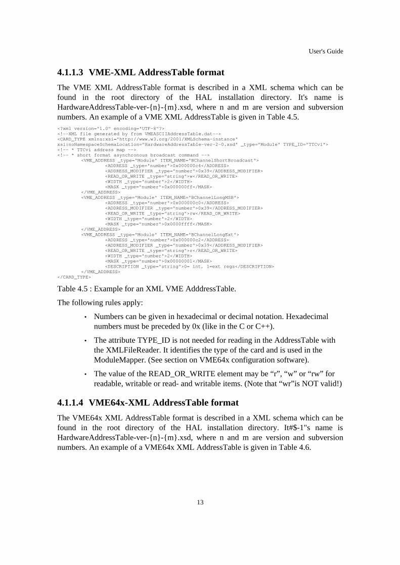
4.1.1.3 VME-XML AddressTable format
The VME XML AddressTable format is described in a XML schema which can befound in the root directory of the HAL installation directory. It's name isHardwareAddressTable-ver-{n}-{m}.xsd, where n and m are version and subversionnumbers. An example of a VME XML AddressTable is given in Table 4.5.<?xml version="1.0" encoding="UTF-8"?><!--XML file generated by from VMEASCIIAddressTable.dat--><CARD_TYPE xmlns:xsi="http://www.w3.org/2001/XMLSchema-instance"xsi:noNamespaceSchemaLocation="HardwareAddressTable-ver-2-0.xsd" _type="Module" TYPE_ID="TTCvi"><!-- * TTCvi address map --><!-- * short format asynchronous broadcast command -->
<VME_ADDRESS _type="Module" ITEM_NAME="BChannelShortBroadcast"><ADDRESS _type="number">0x000000c4</ADDRESS><ADDRESS_MODIFIER _type="number">0x39</ADDRESS_MODIFIER><READ_OR_WRITE _type="string">w</READ_OR_WRITE><WIDTH _type="number">2</WIDTH><MASK _type="number">0x000000ff</MASK>
</VME_ADDRESS><VME_ADDRESS _type="Module" ITEM_NAME="BChannelLongMSB">
<ADDRESS _type="number">0x000000c0</ADDRESS><ADDRESS_MODIFIER _type="number">0x39</ADDRESS_MODIFIER><READ_OR_WRITE _type="string">rw</READ_OR_WRITE><WIDTH _type="number">2</WIDTH><MASK _type="number">0x0000ffff</MASK>
</VME_ADDRESS><VME_ADDRESS _type="Module" ITEM_NAME="BChannelLongExt">
<ADDRESS _type="number">0x000000c2</ADDRESS><ADDRESS_MODIFIER _type="number">0x39</ADDRESS_MODIFIER><READ_OR_WRITE _type="string">r</READ_OR_WRITE><WIDTH _type="number">2</WIDTH><MASK _type="number">0x00000001</MASK><DESCRIPTION _type="string">0= int, 1=ext regs</DESCRIPTION>
</VME_ADDRESS></CARD_TYPE>
Table 4.5 : Example for an XML VME AdddressTable.
The following rules apply:
• Numbers can be given in hexadecimal or decimal notation. Hexadecimalnumbers must be preceded by 0x (like in the C or C++).
• The attribute TYPE_ID is not needed for reading in the AddressTable withthe XMLFileReader. It identifies the type of the card and is used in theModuleMapper. (See section on VME64x configuration software).
• The value of the READ_OR_WRITE element may be “r”, “w” or “rw” forreadable, writable or read- and writable items. (Note that “wr”is NOT valid!)
4.1.1.4 VME64x-XML AddressTable format
The VME64x XML AddressTable format is described in a XML schema which can befound in the root directory of the HAL installation directory. It#$-1"s name isHardwareAddressTable-ver-{n}-{m}.xsd, where n and m are version and subversionnumbers. An example of a VME64x XML AddressTable is given in Table 4.6.
13

User's Guide
<?xml version="1.0" encoding="UTF-8"?><!--XML file generated by from VME64xTable_1.txt--><CARD_TYPE xmlns:xsi="http://www.w3.org/2001/XMLSchema-instance" xsi:noNamespaceSchemaLocation="HardwareAddressTable-ver-2-0.xsd" _type="Module" TYPE_ID="vme64x-1"><!-- ***********************************************--> <!-- * VME64x Address Table : for test purpose --> <!-- ***********************************************-->
<VME64X_ADDRESS _type="Module" ITEM_NAME="vme64x-confItem1"><ADDRESS _type="number">0x00000103</ADDRESS><SPACE _type="string">configuration</SPACE><MAP _type="number">0</MAP><READ_OR_WRITE _type="string">r</READ_OR_WRITE><MASK _type="number">0x000000ff</MASK><DESCRIPTION _type="string">a comment</DESCRIPTION>
</VME64X_ADDRESS><VME64X_ADDRESS _type="Module" ITEM_NAME="vme64x-confItem2">
<ADDRESS _type="number">0x00000107</ADDRESS><SPACE _type="string">configuration</SPACE><MAP _type="number">0</MAP><READ_OR_WRITE _type="string">r</READ_OR_WRITE><MASK _type="number">0x000000ff</MASK><DESCRIPTION _type="string">a somewhat longer comment</DESCRIPTION>
</VME64X_ADDRESS><VME64X_ADDRESS _type="Module" ITEM_NAME="vme64x-item1">
<ADDRESS _type="number">0x00000000</ADDRESS><SPACE _type="string">memory</SPACE><MAP _type="number">0</MAP><READ_OR_WRITE _type="string">rw</READ_OR_WRITE><MASK _type="number">0xffffffff</MASK>
</VME64X_ADDRESS><VME64X_ADDRESS _type="Module" ITEM_NAME="vme64x-item2">
<ADDRESS _type="number">0x00000000</ADDRESS><SPACE _type="string">memory</SPACE><MAP _type="number">2</MAP><READ_OR_WRITE _type="string">rw</READ_OR_WRITE><MASK _type="number">0x00000080</MASK>
</VME64X_ADDRESS></CARD_TYPE>
Table 4.6 : Example of a VME64x AddressTable.
The same rules as for VME Tables apply:
• Numbers can be given in hexadecimal or decimal notation. Hexadecimalnumbers must be preceded by 0x (like in the C or C++).
• The attribute TYPE_ID is not needed for reading in the AddressTable withthe XMLFileReader. It identifies the type of the card and is used in theModuleMapper. (See section on VME64x configuration software).
• The value of the READ_OR_WRITE element may be “r”, ”w” or “rw” forreadable, writable or read- and writable items. (Note that “wr” is NOTvalid!)
4.1.1.5 PCI-XML AddressTable format
The PCI XML AddressTable format is described in a XML schema which can be foundin the root directory of the HAL installation directory. It is the same schema as the onefor VME-XML documents (see previous section). An example of a PCIXMLAddressTable is given in Table 4.7.
14

User's Guide
<?xml version="1.0" encoding="UTF-8"?><!--XML file generated by from TTCrxAddressMap.dat--><CARD_TYPE xmlns:xsi="http://www.w3.org/2001/XMLSchema-instance"xsi:noNamespaceSchemaLocation="HardwareAddressTable-ver-2-0.xsd" _type="Module" TYPE_ID="TTCrxreadout card"><!-- * --><!-- * PLX chip registers --><!-- * -->
<PCI_ADDRESS _type="Module" ITEM_NAME="LocalArbritation"><ADDRESS _type="number">0x000000ac</ADDRESS><BAR _type="number">0</BAR><SPACE _type="string">memory</SPACE><READ_OR_WRITE _type="string">rw</READ_OR_WRITE><MASK _type="number">0xffffffff</MASK>
</PCI_ADDRESS><PCI_ADDRESS _type="Module" ITEM_NAME="BAR0">
<ADDRESS _type="number">0x00000010</ADDRESS><BAR _type="number">0</BAR><READ_OR_WRITE _type="string">rw</READ_OR_WRITE><SPACE _type="string">configuration</SPACE><MASK _type="number">0xffffffff</MASK>
</PCI_ADDRESS><PCI_ADDRESS _type="Module" ITEM_NAME="BAR2">
<ADDRESS _type="number">0x00000018</ADDRESS><BAR _type="number">0</BAR><READ_OR_WRITE _type="string">rw</READ_OR_WRITE><SPACE _type="string">configuration</SPACE><MASK _type="number">0xffffffff</MASK>
</PCI_ADDRESS><PCI_ADDRESS _type="Module" ITEM_NAME="LAS0RR">
<ADDRESS _type="number">0x00000000</ADDRESS><BAR _type="number">0</BAR><READ_OR_WRITE _type="string">rw</READ_OR_WRITE><SPACE _type="string">memory</SPACE><MASK _type="number">0xffffffff</MASK>
</PCI_ADDRESS><PCI_ADDRESS _type="Module" ITEM_NAME="resetFpga">
<ADDRESS _type="number">0x00000000</ADDRESS><BAR _type="number">0</BAR><READ_OR_WRITE _type="string">w</READ_OR_WRITE><SPACE _type="string">memory</SPACE><MASK _type="number">0x00000001</MASK><DESCRIPTION _type="string">resets the FPGA</DESCRIPTION>
</PCI_ADDRESS></CARD_TYPE>
Table 4.7 : Example of an XML PCI AddressTable.
The same rules as for VME XML Address Tables apply with the following restriction:The value of the BAR element may be only a decimal digit in the range of 0 to 5.
4.1.2 The BusAdapter For PCI and VME there exist some BusAdapter interfaces in the library. Theyimplement the interface between the PCIDevice and VMEDevice classes and the driversto access the hardware. Since the different technologies use different concepts to accessthe hardware (which is reflected in the difference of the AddressTables) there exist twodifferent adapter interfaces: the PCIBusAdapterInterface and theVMEBusAdapterInterface. The library contains the following implementations of theseinterfaces:
• The PCIi386BusAdapter in order to access the PCI bus of a Linux PC via thei2o-core library.
15

User's Guide
• The SBS620x86LinuxBusAdapter allows to access VME modules in a crateconnected to a Linux PC via the SBS PC-to-VME Interface (model 618 and620)[2].
• The CANELinuxBusAdapter supports accesses to the USB version and theoptical link version of the CAEN VME Bridge (V1718, V2718 and V2738).
• The MXI2x86LinuxBusAdapter works with the National Instruments VME-to-PC interface. This BusAdapter does not support large block transfers dueto a problem of the interface hardware or the driver software provided byNational. In addition groups have reported that problems arise when thedriver of National is used in a XDAQ application, since it might block thenetwork sockets of the system. It has anyway been included in the HALsince many groups have this interface in their laboratories and might want touse them for testing of hardware. ([email protected]). ThisBusAdapter is not anymore fully supported.
The following two BusAdapters are not any more supported since the VxWorks supporthas been stopped. Since the two classes are fully functional and since they can beconsidered as examples of how to write a BusAdapter they have been left in thedistribution:
• The PCIVxWorksMv2304BusAdapter allows to access PMC cards pluggedonto the Motorola CPU-boards MV2304.
• The VMEVxWorksMv2304BusAdapter allows to access the VME bus intowhich the Motorola CPUs MV2304 is plugged. In case that another Adapteris needed in order to use the library with different hardware, the abovementioned BusAdapters can be used as examples to write a BusAdapter forany specific hardware. More instructions on this are given in Section 6.1.
4.1.3 The Hardware Devices for VME or PCI
The functions the user can perform on a module are defined in theHardwareDeviceInterface. They are technology independent and listed in Table 4.8. Allfunctions which access items in the hardware have an optional parameter ”offset”. Ifused, the value of offset is added to the address of the item. This allows to work witharbitrary Memory regions. For example two items “MemoryBase” and “MemoryTop”can be defined. Operations in this area can be performed with the read and writefunctions referring to the “MemoryBase” item and offset is interpreted as the addressinto the memory region. (The MemoryTop item must be in the memory map in order tolet drivers map the address space of the module into the memory of the user application.Especially if the commands readBlock and writeBlock are used it is important to assurethis. (See Section 4.1.1.1 for details.))
16

User's Guide
function name description
write Write data into an item. The data is shifted to the bit position indicated bythe mask of the item. If the item is readable the bits outside the mask arepreserved by first reading from the address corresponding to the item andthen modifying only those bits which correspond to the items mask. AverifyFlag can be set so that the written value is immediately read back andchecked.
unmaskedWrite Write an item without considering any mask. This command simply writesa data word into the address corresponding to the item. A verifyFlag can beset so that the written value is immediately read back and checked.
writePulse Equal to an unmaskedWrite with data set to 0. This method is used in orderto trigger side effects in the hardware (e.g. a reset). Using it enhancesreadability of the source code.
read Read data from an item. The result is shifted right, so that the bitcorresponding to the least significant bit of the items mask becomes bit 0.
unmaskedRead Read from the address corresponding to the item without shifting the result.
readPulse Equal to an unmaskedRead but no result is returned. This method is used inorder to trigger side effects in the hardware.
setBit Set a single bit in a register. This method can only be used for items ofwhich the mask contains exactly one ‘1’. A verifyFlag can be set so that thewritten value is immediately read back and checked.
resetBit Reset a single bit in a register. This method can only be used for items ofwhich the mask contains exactly one ‘1’. A verifyFlag can be set so that thewritten value is immediately read back and checked.
isSet Test if a bit is set (returns bool). This method can only be used for items ofwhich the mask contains exactly one ‘1’.
check Read an item and test against an expected value. Print out a string if the testis not successful. The main use for this command might be in automatedtesting of hardware with sequences.
readBlock Read a block of data with a specified length as fast as possible into the userapplication. In any case this is a blocking function. It might be specifiedthat the address at the module is held constant in order to read out FIFOS.
writeBlock Write a block of data with a specified length as fast as possible into themodule. In any case this is a blocking function. It might be specified thatthe address at the module is held constant in order to write into FIFOS.
pollItem Poll an item either until it is equal to or different from a given referencevalue. This is a blocking call. A timeout must be given in order to avoid a“hanging” program in case of an error (software or hardware).
getAddressTableInterface Return a reference to the AddressTableInterface for the device.
printAddressTable Print the AddressTable of the device to the console.
Table 4.8 : List of the possible operations on a HardwareDevice.
17
User's Guide
All functions which write data into the hardware device have in addition an optional“verifyFlag” as parameter. If set, the value written into the module is checked byreading it back. In case that the data read back was not the same as written data aVerifyException is raised. (If instead the verifyFlag was set for an item which is notreadable, the IllegalOperationException is raised.) Detailed descriptions of the functionsand their signature can be found in the online documentation of the library. Thisdocumentation is contained in the distribution and can also be browsed locally.
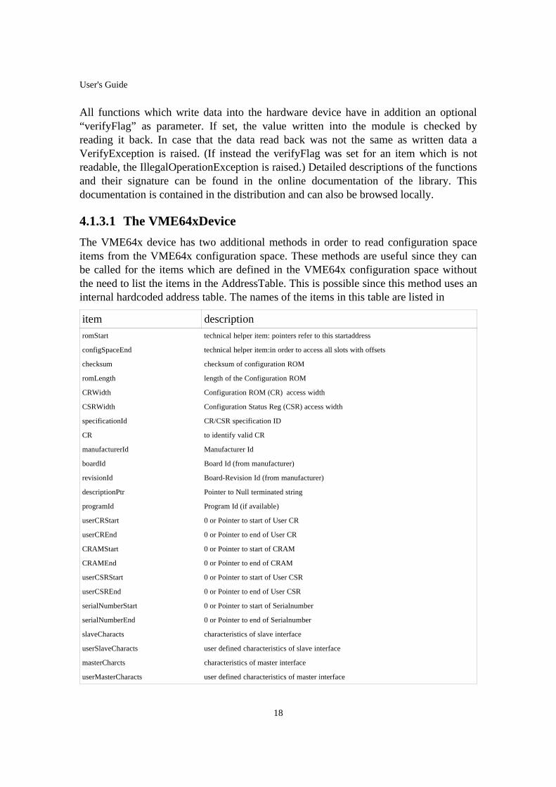
4.1.3.1 The VME64xDevice
The VME64x device has two additional methods in order to read configuration spaceitems from the VME64x configuration space. These methods are useful since they canbe called for the items which are defined in the VME64x configuration space withoutthe need to list the items in the AddressTable. This is possible since this method uses aninternal hardcoded address table. The names of the items in this table are listed in
item descriptionromStart technical helper item: pointers refer to this startaddress
configSpaceEnd technical helper item:in order to access all slots with offsets
checksum checksum of configuration ROM
romLength length of the Configuration ROM
CRWidth Configuration ROM (CR) access width
CSRWidth Configuration Status Reg (CSR) access width
specificationId CR/CSR specification ID
CR to identify valid CR
manufacturerId Manufacturer Id
boardId Board Id (from manufacturer)
revisionId Board-Revision Id (from manufacturer)
descriptionPtr Pointer to Null terminated string
programId Program Id (if available)
userCRStart 0 or Pointer to start of User CR
userCREnd 0 or Pointer to end of User CR
CRAMStart 0 or Pointer to start of CRAM
CRAMEnd 0 or Pointer to end of CRAM
userCSRStart 0 or Pointer to start of User CSR
userCSREnd 0 or Pointer to end of User CSR
serialNumberStart 0 or Pointer to start of Serialnumber
serialNumberEnd 0 or Pointer to end of Serialnumber
slaveCharacts characteristics of slave interface
userSlaveCharacts user defined characteristics of slave interface
masterCharcts characteristics of master interface
userMasterCharacts user defined characteristics of master interface
18

User's Guide
item descriptionirqHandlerCap interrupt handler capabilities
interrupterCap interrupter capabilities
CRAMWidth Configuration RAM (CRAM) access width
dataAccessWidth-F0 Data access width for function 0
dataAccessWidth-F1 Data access width for function 1
dataAccessWidth-F2 Data access width for function 2
dataAccessWidth-F3 Data access width for function 3
dataAccessWidth-F4 Data access width for function 4
dataAccessWidth-F5 Data access width for function 5
dataAccessWidth-F6 Data access width for function 6
dataAccessWidth-F7 Data access width for function 7
AMCAP-F0-1 AM-capability for function 0: byte 7
AMCAP-F0-0 AM-capability for function 0: byte 3
AMCAP-F1-1 AM-capability for function 1: byte 7
AMCAP-F1-0 AM-capability for function 1: byte 3
AMCAP-F2-1 AM-capability for function 2: byte 7
AMCAP-F2-0 AM-capability for function 2: byte 3
AMCAP-F3-1 AM-capability for function 3: byte 7
AMCAP-F3-0 AM-capability for function 3: byte 3
AMCAP-F4-1 AM-capability for function 4: byte 7
AMCAP-F4-0 AM-capability for function 4: byte 3
AMCAP-F5-1 AM-capability for function 5: byte 7
AMCAP-F5-0 AM-capability for function 5: byte 3
AMCAP-F6-1 AM-capability for function 6: byte 7
AMCAP-F6-0 AM-capability for function 6: byte 3
AMCAP-F7-1 AM-capability for function 7: byte 7
AMCAP-F7-0 AM-capability for function 7: byte 3
XAMCAP-F0-7 XAM-capability for function 0: word 7
XAMCAP-F1-7 XAM-capability for function 1: word 7
XAMCAP-F2-7 XAM-capability for function 2: word 7
XAMCAP-F3-7 XAM-capability for function 3: word 7
XAMCAP-F4-7 XAM-capability for function 4: word 7
XAMCAP-F5-7 XAM-capability for function 5: word 7
XAMCAP-F6-7 XAM-capability for function 6: word 7
XAMCAP-F7-7 XAM-capability for function 7: word 7
XAMCAP-F0-6 XAM-capability for function 0: word 6
XAMCAP-F1-6 XAM-capability for function 1: word 6
XAMCAP-F2-6 XAM-capability for function 2: word 6
XAMCAP-F3-6 XAM-capability for function 3: word 6
XAMCAP-F4-6 XAM-capability for function 4: word 6
19

User's Guide
item descriptionXAMCAP-F5-6 XAM-capability for function 5: word 6
XAMCAP-F6-6 XAM-capability for function 6: word 6
XAMCAP-F7-6 XAM-capability for function 7: word 6
XAMCAP-F0-5 XAM-capability for function 0: word 5
XAMCAP-F1-5 XAM-capability for function 1: word 5
XAMCAP-F2-5 XAM-capability for function 2: word 5
XAMCAP-F3-5 XAM-capability for function 3: word 5
XAMCAP-F4-5 XAM-capability for function 4: word 5
XAMCAP-F5-5 XAM-capability for function 5: word 5
XAMCAP-F6-5 XAM-capability for function 6: word 5
XAMCAP-F7-5 XAM-capability for function 7: word 5
XAMCAP-F0-4 XAM-capability for function 0: word 4
XAMCAP-F1-4 XAM-capability for function 1: word 4
XAMCAP-F2-4 XAM-capability for function 2: word 4
XAMCAP-F3-4 XAM-capability for function 3: word 4
XAMCAP-F4-4 XAM-capability for function 4: word 4
XAMCAP-F5-4 XAM-capability for function 5: word 4
XAMCAP-F6-4 XAM-capability for function 6: word 4
XAMCAP-F7-4 XAM-capability for function 7: word 4
XAMCAP-F0-3 XAM-capability for function 0: word 3
XAMCAP-F1-3 XAM-capability for function 1: word 3
XAMCAP-F2-3 XAM-capability for function 2: word 3
XAMCAP-F3-3 XAM-capability for function 3: word 3
XAMCAP-F4-3 XAM-capability for function 4: word 3
XAMCAP-F5-3 XAM-capability for function 5: word 3
XAMCAP-F6-3 XAM-capability for function 6: word 3
XAMCAP-F7-3 XAM-capability for function 7: word 3
XAMCAP-F0-2 XAM-capability for function 0: word 2
XAMCAP-F1-2 XAM-capability for function 1: word 2
XAMCAP-F2-2 XAM-capability for function 2: word 2
XAMCAP-F3-2 XAM-capability for function 3: word 2
XAMCAP-F4-2 XAM-capability for function 4: word 2
XAMCAP-F5-2 XAM-capability for function 5: word 2
XAMCAP-F6-2 XAM-capability for function 6: word 2
XAMCAP-F7-2 XAM-capability for function 7: word 2
XAMCAP-F0-1 XAM-capability for function 0: word 1
XAMCAP-F1-1 XAM-capability for function 1: word 1
XAMCAP-F2-1 XAM-capability for function 2: word 1
XAMCAP-F3-1 XAM-capability for function 3: word 1
XAMCAP-F4-1 XAM-capability for function 4: word 1
20

User's Guide
item descriptionXAMCAP-F5-1 XAM-capability for function 5: word 1
XAMCAP-F6-1 XAM-capability for function 6: word 1
XAMCAP-F7-1 XAM-capability for function 7: word 1
XAMCAP-F0-0 XAM-capability for function 0: word 0
XAMCAP-F1-0 XAM-capability for function 1: word 0
XAMCAP-F2-0 XAM-capability for function 2: word 0
XAMCAP-F3-0 XAM-capability for function 3: word 0
XAMCAP-F4-0 XAM-capability for function 4: word 0
XAMCAP-F5-0 XAM-capability for function 5: word 0
XAMCAP-F6-0 XAM-capability for function 6: word 0
XAMCAP-F7-0 XAM-capability for function 7: word 0
ADEM-F0 Address Decoder Mask function 0
ADEM-F1 Address Decoder Mask function 1
ADEM-F2 Address Decoder Mask function 2
ADEM-F3 Address Decoder Mask function 3
ADEM-F4 Address Decoder Mask function 4
ADEM-F5 Address Decoder Mask function 5
ADEM-F6 Address Decoder Mask function 6
ADEM-F7 Address Decoder Mask function 7
bar CR/CSR Base Address Register (BAR)
bitSet Bit Set Register
bitClear Bit Clear Register
cramOwner CRAM owner Register
userBitSet User Bit Set Register
userBitClear User Bit Clear Register
ADER-F7 Address Decoder Compare Register function 7
ADER-F6 Address Decoder Compare Register function 6
ADER-F5 Address Decoder Compare Register function 5
ADER-F4 Address Decoder Compare Register function 4
ADER-F3 Address Decoder Compare Register function 3
ADER-F2 Address Decoder Compare Register function 2
ADER-F1 Address Decoder Compare Register function 1
ADER-F0 Address Decoder Compare Register function 0
CSRStart Marks start of CSR space
Table 4.9 : Names of the Configuration space items predefined by the VME64xstandard. These items are contained in a hardcoded AddressTable (classVMEConfigurationSpaceAddressReader)
Examples
21

User's Guide
4.2 Complete Example ProgramThe following example shows a small C++ program which is using the hardware accesslibrary to access a hardware module in a PCI system.
Listing 1 declares a hardware module class. It inherits from the PCIDevice class andtherefore it needs the same arguments in the constructor. This class could containmethods which are specific to the G3RuiCard. (In this example it doesn't): #ifndef __G3RuiCard#define __G3RuiCard
#include "MessageLogger.hh"#include "PCIDevice.hh"#include "PCIAddressTable.hh"#include "PCIBusAdapterInterface.hh"
// side remark: The strange tags in the comments are needed for the // doxygen tool to generate automatically html documentation// for this class.
/** * A class to implenent specific functionality of the G3RuiCard * * In the "real world" this class would contain additional methods * which provide specific services useful for the card. For example * a method "setup" could be written in order to bring the card into * a default operational mode. * In this simple example we only put the constructor in this class * and leave it to the phantasie of the user to extend this class * with functionality adequate for his own modules. * */class G3RuiCard : public PCIDevice {
/** * @name PCI Configuration Space * The following constants are relevant if dealing directly with * the PCI interface. They are NOT used in the implementation file * but ususally you need them in the constructor of the * PCIReadWriteInterface. *//* @{ */#define G3RUI_VENDORID 0xecd6 /**< needed to search for the device */#define G3RUI_DEVICEID 0x16bd /**< needed to search for the device *//* @} */
public : /** * The arguments of the constructor of the G3RuiCard will be passed * to the constructor of the PCIDevice. Note that the vendorID and * the deviceID of this module are defined above within this class. * (May be it would be nicer to define const private members for * this since then no namespace problems can arise.) **/ G3RuiCard( PCIAddressTable & addressTable, PCIBusAdapterInterface & pciBusAdapter, unsigned long pciIndex);
private: MessageLogger errorLogger; PCIBusAdapterInterface& pciBusAdapter;};
#endif /* __G3RuiCard */
Table 4.10 : A simple header file for a PCI card.
Here follows the corresponding implementation file G3RuiCard.cc:
22

User's Guide
#include "G3RuiCard.hh"
G3RuiCard::G3RuiCard( PCIAddressTable & addressTable, PCIBusAdapterInterface & pciBusAdapter, unsigned long pciIndex) : PCIDevice( addressTable, pciBusAdapter, G3RUI_VENDORID, G3RUI_DEVICEID, pciIndex ), errorLogger("G3RuiCard"), pciBusAdapter(pciBusAdapter) { }
Table 4.11 : The listing of the implementatinon file G3RuiCard.cc.
And finally a simple main program asking the user, what he wants to read or write: #include "G3RuiCard.hh"#include "PCIDevice.hh"#include "PCIAddressTable.hh"#include "PCIAddressTableASCIIReader.hh"#include "PCIi386BusAdapter.hh"
#include <iostream>
#define GIIIADDRESSTABLE "GIIIAddressTable.dat"
int main() { try { PCIi386BusAdapter busAdapter; PCIAddressTableASCIIReader addressTableReader( GIIIADDRESSTABLE ); PCIAddressTable addressTable( "Test address table", addressTableReader ); G3RuiCard gIIICard(addressTable, busAdapter, 0);
bool loop = true; string item; int option; unsigned long value;
while ( loop ) { cout << "1) write to item" << endl; cout << "2) read from item" << endl; cout << "Enter option : "; cin >> option;
switch (option) { case 0: loop = false; break; case 1: cout << "Enter item : "; cin >> item; cout << "Enter value (hex) : "; cin >> hex >> value; gIIICard.write( item, value ); break; case 2: cout << "Enter item : "; cin >> item; gIIICard.read( item, &value ); cout << "result : " << hex << setfill('0') << setw(8) << value << endl; break; } } } catch ( HardwareAccessException& e ) { cout << "exxceptional exception : " << endl; cout << e.what() << endl; } catch ( exception e ) { cout << "another exception..." << endl; } return 0;}
Table 4.12 : Listing of the main program G3Tester.cc.
23

User's Guide
4.3 The sequencer The sequencer allows to execute sequences of commands which have been previouslydefined and stored. Similar to the AddressTables a reader reads in a representation of theSequence. Currently only ASCII file representations of sequences are supported. Asequence is bound to an AddressTable since its commands need the items definedtherein. On the other hand it is independent of a specific hardware module. A sequencecan therefore be executed on different modules of the same kind (that means re brackets.
4.3.1 Commands of the Sequencer The main goal of the Sequencer is to enable the user to easily change initializationprocedures in the debugging phase of hardware setups. In order to do this the Sequencersupports commands of the HardwareDeviceInterface which write data into the hardwareor which read data from the hardware. In addition some minimal support for variables isimplemented in order to be able to parametrize sequences. Variables can be set by theuser program or by read commands in a sequence. There is the possibility to createsimple loops. Labels in the sequence can be defined. With the goto command aconditional jump to a label can be performed. The expression containing the conditionallows to set two operands which might be constants or variables into relation.
For debugging purposes there is a very simple print command which can print outstrings and values of variables in hexadecimal or decimal format.
Table 11 lists the available commands and their meaning. If the commands are notfurther explained in the table, their meaning is the same as the equivalent method in theHardwareDeviceInterface. Optional values are put into square brackets.
command description
write item data [verifyFlag] [offset] Data and offset may be variables or constants.
unmaskedWrite item data [verifyFlag][offset]
Data and offset may be variables or constants.
setBit item [verifyFlag] [offset] Offset may be a variable or a constant.
resetBit item [verifyFlag] [offset] Offset may be a variable or a constant.
24

User's Guide
command description
define name [initValue] A variable is defined with this command. Variable namesMUST begin with a “$”. If no initValue is given thevariable has initially (that means when the Sequence iscreated at start-up) the value 0. Thereafter the value of thevariable is not further affected if the sequence is executed.This is important to remember if the sequence is executedmore than one time. The second time, the start value of thevariable is the value the variable had when the previousexecution of the sequence stopped. On the other hand if aninitial Value is given this is assigned to the variable eachtime the execution of the sequence arrives at this command.The initValue must be a constant.
add name value Value is added to the value of the variable name. value canbe a constant or a variable itself.
read item variable [offset] The read value is stored in a previously defined variable.
unmaskedRead item variable [offset] The read value is stored in a previously defined variable.
check item expectedValue [offset] [string] If the check is not successful ALWAYS a string is printedout containing the item name the read value and theexpected value. if the optional parameter string is given it isalso printed.
pollItem item referenceValue timeoutvariable [pollMethod] [offset]
The timeout is given in milliseconds. The pollMethoddetermines if the call return on the item to be equal to ordifferent from the reference- Value.The variable containsthe value of the last poll if the timeout has not expired. Ifthe timeout expires an exception is thrown and thesequence execution is not continued.
label name A new label with the given name is defined.
goto label op1 cond op2 When the condition between op1 and op2 is satisfied,execution is continued at label. Op1 and op2 may bevariables or constant values. Allowed conditions are thestrings “==”, “<=”, “>=”, “<“, “>”,”!=”. print argumentsThe arguments are a sequence of words. Words which startwith the ‘$’ sign are interpreted as variable names. Twoformatting options are available: “%hex” in front of avariable displays the data in hex format (8 digits) whereas“%dec” switches formatting back to decimal integernumber format.
Table 4.13 : List of commands supported by the sequencer.
Notes:
• Commands are case sensitive.
• The verifyFlag must take either of the two values “HAL_DO_VERIFY” or“HAL_NO_VERIFY”.
25

User's Guide
• The pollMethod must take either of the two values“HAL_POLL_UNTIL_EQUAL” or “HAL_POLL_UNTIL_DIFFERENT”.
• If working with offsets the user must make sure that the highest possibleaddress (for the relevant base address in case of a PCI module) is containedin the AddressMap.
• Constant values might be given in hex or decimal format (e.g: “0x00ff” or“255”).
• If an offset is given as a argument to a command also the verifyFlag must bespecified.
4.3.2 Example Program The following example program creates a PCIDevice and a Sequencer. Then it buildsone Sequence which it registers with the Sequencer. Before running the Sequence it setsa variable named "$first" to a specific value. This variable must be defined in theSequence otherwise an exception
"SequencerSyntaxError" is thrown. Note: the variables are actually created andregistered internally at creation time of the Sequence when reading the sequence fromthe corresponding reader. However the initialization value (if given) is assigned whenthe execution arrives at the "define"- statement of the variable.
26

User's Guide
1: #include <iostream> 2: #include <string> 3: #include "PCIAddressTableASCIIReader.hh" 4: #include "VMEAddressTableASCIIReader.hh" 5: #include "PCIAddressTable.hh" 6: #include "VMEAddressTable.hh" 7: #include "CommandSequencer.hh" 8: #include "CommandSequenceASCIIReader.hh" 9: #include "PCIi386BusAdapter.hh" 10: #include "G3RuiCard.hh" 11: 12: #define SEQUENCE_FILE "Sequence.dat" 13: 14: #define PCI_TABLE "PCITestTable.dat" 15: #define VME_TABLE "VMETestTable.dat" 16: 17: int main() { 18: 19: try {20: PCIAddressTableASCIIReader pciTableReader(PCI_TABLE); 21: PCIAddressTable pciTable( string("PCI test-table"), pciTableReader); 22: pciTable.print(); 23: 24: PCIi386BusAdapter busAdapter; 25: G3RuiCard gIIICard(pciTable, busAdapter, 0); 26: 27: CommandSequencer sequencer; 28: CommandSequenceASCIIReader myReader( SEQUENCE_FILE ); 29: CommandSequence firstSequence( "firstSequence", 30: &myReader, 31: pciTable); 32: sequencer.registerSequence( firstSequence ); 33: unsigned long var = firstSequence.getVariable( "$first" ); 34: cout << "var : òü << var << endl; 35: firstSequence.setVariable( "$first", 0x999 ); 36: var = firstSequence.getVariable( "$first" ); 37: cout << "var : òü << var << endl; 38: sequencer.run("firstSequence", gIIICard); 39: } catch (HardwareAccessException& e) { 40: cout << e.what() << endl; 41: } catch (exception& ex) { 42: cout << "another exception" << endl; 43: cout << ex.what() << endl; 44: }45: }46:
Table 4.14 : A small test program which works with Sequences.
An example of a valid sequence is given below: # This is a small test sequencedefine $first 8 define $valuedefine $offset 0x0000add $first 4write memStart 0x2000write mem0 0x10 write mem1 0x11write mem2 0x30write memStart 0x22 no_verify 8write memStart 0x33 no_verify $firstwrite memStart 0x44 no_verify 0x10
# print out 256 bytes of memory in a looplabel loopread $memStart $value $offsetprint %hex address : $offset value : $valueadd $offset 4goto loop $offset < 0x100print This is the end
Table 4.15 : An example of a Sequence.
27

User's Guide
4.4 Examples in the distribution The HAL distribution contains four examples which can be run in order to get startedwith the HAL library.
• A small test program to control the TTCvi VME module.
• A test program to experiment with XML address tables.
• A small performance measurement suite.
• An XDAQ application using the HAL. This example is only useful if theHAL is installed and used in the XDAQ context. It contains nothing newwith respect to the previous examples except that it shows how to compileand link an XDAQ application using the HAL.
4.4.1 The TTCviConsole example This program allows to control the TTCvi VME module. It reads in the address table ofthe TTCvi (as a ASCII file) and then allows the user to "play" with the TTCvi in aninteractive menu driven loop. In addition sequences might be registered deleted, andexecuted. Sequences are saved in ASCII files. The program remembers the registeredsequences. For this purpose a class "PersistentCommandSequencer" has beendeveloped. Since this class might be useful in many test programs it has been put in theseparate "tools" library in the examples directory. This library can be used and extendedby the user.
The TTCviConsole uses a VMEDummyBusAdapter so that it can be compiled with anyplatform, and that it can be used without any real hardware attached. It is sufficient tochange two lines in the source file TTCviConsole.cc (the include statement and theinstantiation of the BusAdapter) in order to adapt the program to a real hardware setupconnected to the computer.
4.4.2 The XMLAddressTableTester example This program allows to experiment with XML address tables. Two differentAddressTables are built by the program using the AddressTableXMLFileReader. Thefirst AddressTable is read in correctly. In the second AddressTables some syntax errorsexist. Since the AddressTable is automatically checked against the correspondingSchema the Syntax Errors are detected and reported by an exception which is thrown.
The user should try to correct the erroneous XML-file.
28

User's Guide
4.4.3 The PerformanceTester The program uses the VMEDummyBusAdapter without memory mapping in order tomeasure the overhead introduced by the HAL library. Since verbosity is switched off theBusAdapter reduces to an empty function call and does not consume significant time.The test invokes different calls of the HardwareDeviceInterface in a loop and measuresthe time needed for the execution. In the end the overhead for each function call isprinted out. This must be compared with the overhead introduced by the driver (the usermust measure these independently).
It can be very instructive to play with compiler optimization options. The overhead isreduced significantly for most of the calls by compiling the HAL with the -O3 option.
4.4.4 The XDAQ application "Trigger" This example contains a small XDAQ application which controls the TTCvi VMEmodule. In a short README.txt file in the directory hal/examples/XDAQ/Trigger youfind information to needed in order to change the BusAdapter of the example (perdefault the example is using the VMEDummyBusAdapter). The most interesting aspectof this example is the Makefile in the directory hal/examples/XDAQ/src/linux/x86. It isdocumented and contains the necessary information on how to compile and link aXDAQ application which uses the HAL.
4.5 VME64x Plug And Play Support It is recommended that custom VME modules in CMS, if possible, should be VME64xcompliant and should implement those parts of the VME64x specification which allowthe plug and play configuration of a VME crate. This makes maintenance easier for non-experts which is of great interest in an experiment like CMS, that is expected to beoperated for more than 10 years by frequently changing maintenance personal.[1]
The HAL contains a set of classes in order to perform this plug and play configuration.The aim is to provide the user an interface which he can use in order to retrieve a theVMEDevices plugged into the crate. These can then be used in the same way asdescribed in the previous sections. The automatic configuration will identify themodules, map the modules into the VME address space and finally construct theVMEDevices. The software can be given a so called static configuration containinginformation on non-plug-and-play modules in the crate, so that the VME64x modulescan be mapped around existing VME modules.
The following section describes some details of these steps. It is followed by a shortdiscussion of the user-API and various aspects of the current implementation.
29

User's Guide
4.5.1 Steps during the VME64x Plug and Play configuration. The plug and play configuration in the HAL uses two different sources of information.The first is the data found in the CR space of the VME64x modules. They contain thecapability and address space requirements of the module. In addition a serial numberfound therein is used to retrieved further information about the module in the seconddata source. This information consists of the address table of the module. Two steps arenecessary in order to find the Address Table for a module: The ModuleMapper retrievesthe type of the module by inspecting its serial number. Every type is unambiguouslyassociated with an AddressTable. In praxis the information for the ModuleMapper andthe Addresstables are retrieved from a database.
The following steps are performed during configuration of a crate:
1. The configuration space of the crate is scanned for VME64x modules. Thisis done by scanning the CR of all slots for valid VME64x identifiers. (The"CR" and the VME version numbers are tested.) In case a static VMEconfiguration has been given, only those slots are scanned which are not yetoccupied by a static configuration item. If a module is found on the amnesiaaddress an exception is thrown.If a VME64x module is found which hasalready been configured (i.e. its enable bit in the CSR bit is set) it is treatedlike a standard VME module with a static configuration. This means thesoftware reads out the configuration data from the CR and the CSR spaceand does not touch the configuration of the module any further. This isimportant since it could be that the module is in use by another program andtherefore it must not be re-configured.
2. The serial number of the modules found is read out.
3. The ModuleMapper associates the serial number with a type_id for themodule.
4. The type_id of the module is used to retrieve the AddressTable of themodule.
5. The address space requirements and the capabilities of the module areretrieved from the configuration space.
6. The address space of the whole crate is mapped under consideration of thestatic configuration for standard VME modules with fixed base addressesand the configuration of already enabled VME64x modules.
7. The address modifiers used to access the VME modules are determined foreach mapped VME64x window according to a simple priority scheme.
8. The ADER registers of the not already configured VME64x modules are setwith the base addresses and the AMs the HAL will use to access the variousmapped windows.
30

User's Guide
9. All mapped VME64x modules will be enabled.
10. The user can retrieve the VMEDevices via the API of the crate.
4.5.2 Implementation details The generic part of the HAL does only define the interfaces to retrieve the type_id or theAddressTables. The ModuleMapperInterface maps the serial number to type_id. This isthen used in order to retrieve the AddressTable of the module from theAddressTableContainerInterface. The current version of the HAL contains for bothinterfaces an implementation which retrieves the relevant information from an ASCIIfile.
31

BusAdapters and Device Drivers
5 BusAdapters and Device Drivers
5.1 What are Bus Adapters? In order to access the hardware a device driver is needed which initiates the data transferon the bus system housing the hardware modules. It is an operating system and ahardware interface specific piece of software sitting between application programs andthe hardware itself (VME bus or PCI bus). The software interface of the device driver tothe application is driver specific. Therefore it is not possible to write generic code whichinterfaces with arbitrary device drivers.
The hardware access library instead provides a BusAdapter class which wraps the driverspecific API. The BusAdapterInterface class provides an interface used by the hardwareaccess library in order to communicate with the device driver which in turn inducesdatatransfer cycleson the bus. For each device driver a specific implementation of thisinterface has to be provided.
The user application has to instantiate one BusAdapter per bus system.
5.2 BusAdapters contained in the library The library supports VME and PCI hardware and includes some BusAdapters for eachtechnology. For PCI there are provided two adapters:
• PCIi386BusAdapter: for Linux PCs with the i2o-core package which servesas a generic PCI device driver. It allows to access hardware PCI modulesplugged into a PC.
• SBS620x86LinuxBusAdapter: for the PC to VME interface of the companySBS (Model 620). It allows to access modules plugged into the VME-cratecontrolled by the SBS interface [2].
• MXI2x86LinuxBusAdapter: works with the National Instruments VME-to-PC interface. (This BusAdapter has been essentially written [email protected]).
So called dummy BusAdapters are available in order to test software without havingreal hardware connected to the computer. These BusAdapters are useful during thedebugging phase of the software. They can be configured operate in a memory mappedmode: this means that instead of writing and reading the real hardware, a memoryregion in the host computer is used to for read and write commands. This allows to readback data which previously have been written. Three dummy BusAdapters are provided:
• The VMEDummyBusAdapter can be used to simulate standard VMEmodules.
32

BusAdapters and Device Drivers
• ThePCIDummyBusAdapter can be used to simulate standard PCI modules.
• The VME64xDummyBusAdapter can be used to simultate VME64x. ThisBusAdapter also simulates the CR and the CSR space of VME64x modulesso that the automatic configuration of a VME64x crate can be simulated. ThebusAdapter needs a file with a description of the contents of the crate. Inaddition files with the CR content of the VME64x modules must beprovided. Details can be found in the VME64xDummyBusAdapter APIhtml-documentation.
The following BusAdapters are just as examples in the Library but note that there is noVxWorks support any more for the HAL library:
• VMEVxWorksMv2304BusAdapter: for the Motorola CPU MV2304 runningVxWorks. It allows to access hardware plugged into VME crate controlledby the Motorola CPU.
• PCIVxWorksMv2304BusAdapter: for the Motorola CPU MV2304 runningVxWorks. It allows to access hardware plugged into the PMC slots of theCPU.
In case the user wants to use the library with another technology, hardware interface oroperating system he just has to write an implementation of the BusAdpaterInterface forhis system. Details of this are discussed in Section 6.1.
33

Write your own extensions
6 Write your own extensionsThis you do not need to read if you are satisfied with the functionality of the library.However there are some situations in which you might want to extend the library withsome classes written by you:
• You have a hardware interface to your bus (VME or PCI) for which noBusAdapter is available in the standard library. In this case you might wantto write a BusAdapter for your driver.
• Thesources for the library are not readable with the reader-implementationsof this library. In this case you might to write your own reader to access yourconfiguration data. This situation might occur for the AddressTables and forthe Sequencer.
The following sections give details on how to write an implementation for the abovementioned classes.
6.1 The BusAdapter In the library you find examples for BusAdapters. Looking at the source code of theseexamples will help to write a new BusAdapter.
6.1.1 PCI BusAdapters A BusAdapter for PCI must implement the PCIBusAdapterInterface. Currently it ispossible to access items in a PCI device in either memory or configuration space. Thedriver must be able to unambiguously locate the hardware module. For a memorymapped module this is possible with a single address. If the driver used other methodsto access the module it might need more information than only an address in order toidentify the module. This information is contained in an object which is derived fromthe DeviceIdentifier class. For every driver a DeviceIdentifier has to be implementedwhich contains all necessary information for the driver to identify the device.
The following functions must be implemented (please look up the signatures of themethods in the online code documentation):
34

Write your own extensions
function arguments description
findDevice vendorIDdeviceIDindexpciAddressTabledeviceIdentifierPtrbaseAddresses
This function is used to find the hardware module with theparameters vendorID, deviceID and index on the bus. It returns apointer to a deviceIdentifier which is needed for configuration spaceaccesses. In addition a reference to a vector containing the baseaddresses of the 6 BARs is returned. A ‘0’ in this vector indicatesthat the corresponding BAR is not used. The values contained in thisvector are not necessarily the same as those read from the module’sPCI configuration-space. It is the base address to which the addressvalues of the AddressTables is added to access the logical items ofthe AddressTable. If a device driver is mapping the modules addressspace into memory, this vector contains the base addresses of thesemaps. The pciAddressTable is also given to the routine because incase that the device will be mapped in memory by the driver, thetable must be scanned in order to determine the size of the maps foreach BAR. closeDevice deviceIdentifier This function is used to dothe necessary cleanup in the driver. For example for memory mappeddevices the maps are destroyed and the reserved space is returned tothe operating system.In any case the deviceIdentifier must be deletedher.
configWrite deviceaddressdata
This function writes a data word into configuration space. The deviceArgument refers to the DeviceIdentifier containing all data which thedriver needs to access configuration space items. The addressargument is the offset in the configuration space.
configRead deviceaddressresultPtr
This function reads a data word from the configuration space into thelocation pointed to by resultPtr. The arguments are the same as forthe configWrite command.
write deviceaddressdata
This function writes data word to a specific address. The deviceargument contains all relevant information for the driver tounambiguously identify the hardware module. (For memory mappedmodules this argument is probably dummy like in thePCIi386BusAdapter.) The address argument contains the sum of thecorresponding baseAddress from the findDevice call and the offsetretrieved from the AddressTable.
read deviceaddressresultPtr
The function reads a data word into the location pointed to byrestultPtr. The address is calculated in the same way as for the writecommand.
Table 6.1 : Functions which must be implemented by a PCI BusAdapter.
6.1.2 VME BusAdapters The interface for VME BusAdapters is simpler than that for PCIBusAdapter. The twofunctions to implement are listed in Table 13. Please consult the online documentationof the library for precise information on the signature of the functions.
35

Write your own extensions
function arguments description
openDevice VMEAddressTableVMEBaseAddressdeviceIdentifierPtrbaseAddressPtr
This call allows the driver to prepare to access a new module. Thecall creates a new object which inherits from “DeviceIdentifier”.This object will be passed to all subsequent read and write accessesand therefore can be used to store all parameters the driver needs toaccess the hardware module. The pointer to this object is returnedin the deviceIdentifierPtrPtr. (The argument is a pointer to apointer.) As a second parameter the routines needs to return abaseAddress to the caller in the baseAddressPtr. This can be usefulfor memory mapped drivers where the VMEBaseAddress of themodule and the size of the AddressTable are used to compute anew virtual address space. The baseaddress of the latter can bereturned by the routine. It is this returned address which is used bythe VMEDevice to calculate the item’s addresses which are passedto the write and read routines below. (Of course, for other driverarchitecture it is also possible to return the originalVMEBaseAddress).
closeDevice deviceIdentifierPtr This function is used to do the necessary cleanup in the driver. Forexample for memory mapped devices the maps are destroyed andthe reserved space is returned to the operating system. In any casethe deviceIdentifier must be deleted her.
write deviceIdentifierPtraddressaddressModifierdataWidthdata
Writes a data word into the hardware module. The addressModifieris defined in the VME specification. The address is calculated byadding the items address from the AddressTable to thebaseAddress returned by the openDevice method above. ThedataWidth is the width of the access in bytes (usually only 2 or 4are used).
read deviceIdentifierPtraddressaddressModifierdataWidthresultPtr
Reads a data word from the hardware module into the locationpointed to by resultPtr. The addressModifier is defined in the VMEspecification. The address is calculated by adding the items addressfrom the AddressTable to the baseAddress returned by theopenDevice method above. The dataWidth is the width of theaccess in bytes (usually only 2 or 4 are used).
writeBlock eviceIdentifierPtrstartAddresslengthaddressModifierdataWidthbufferPtraddressBehaviour
Write a block of data contained at the location pointer to by“bufferPtr” into the module beginning at address “startAddress”.The length of the block in bytes is contained in “length”.“addressBehaviour” specifies if the address at the module isincremented or not (the latter option is needed in order to write intoFIFOs).
readBlock deviceIdentifierPtrstartAddresslengthaddressModifierdataWidthbufferPtraddressBehaviour
Read a block of data from the module starting at “startAddress”into a buffer pointed to by “bufferPtr”. The length of the block inbytes is contained in “length”. “addressBehaviour” specifies if theaddress at the module is incremented or not (the latter option isneeded in order to read FIFOs).
Table 6.2 : Functions which must be implemnted by a VMEBusAdapter.
36

Write your own extensions
6.2 The AddressTableReader When an AddressTable is constructed it reads the relevant data from anAddressTableReader (which is given as an argument to the constructor). The library isproviding classes to read the AddressTables of VME or PCI devices from an ASCII file.
If the user has stored the AddressTables on another media or in another format he mustprovide a suitable reader on his own. An implementation for a specificAddressTableReader must inherit from the class AddressTableReader. It thenautomatically inherits all necessary functionality in order to "feed" an AddressTable attime of its construction.
A valid AddressTableReader needs to fill the itemPointerList (a protected data memberof the class AddressTableReader) with the AddressTableItems which the AddressTableshould contain. (Either for PCI or for VME.)
Examples of AddressTableReaders contained in the library arePCIAddressTableASCIIReader and VMEAddressTableASCIIReader. Please consult theonline documentation for further details.
6.3 The CommandSequenceReader Similarly to the AddressTables, Sequences are constructed by reading the data from asuitable reader. The library provides a reader containing the sequence in a flat ASCIIfile.
A new specific reader for CommandSequences must inherit from theCommandSequenceReader class and fill the protected data structure commandList. ThecommandList itself contains lists of strings which from the commands. An example of aspecific CommandSequenceReader which reads in Sequences from a flat file is theCommandSequenceASCIIReader. Please consult the online documentation for furtherdetails.
37