halle - ari · pdf filehalle a member of the ari group edition 04/17 ... • thermostatic...
TRANSCRIPT
AWH ARMATUREN-�WERK HALLE GMBH
®
HALLE
A member of the ARI group
Edition 04/18 - Data subject to alteration - Regularly updated data on www.ari-armaturen.com! Data sheet 600001 englisch (english)
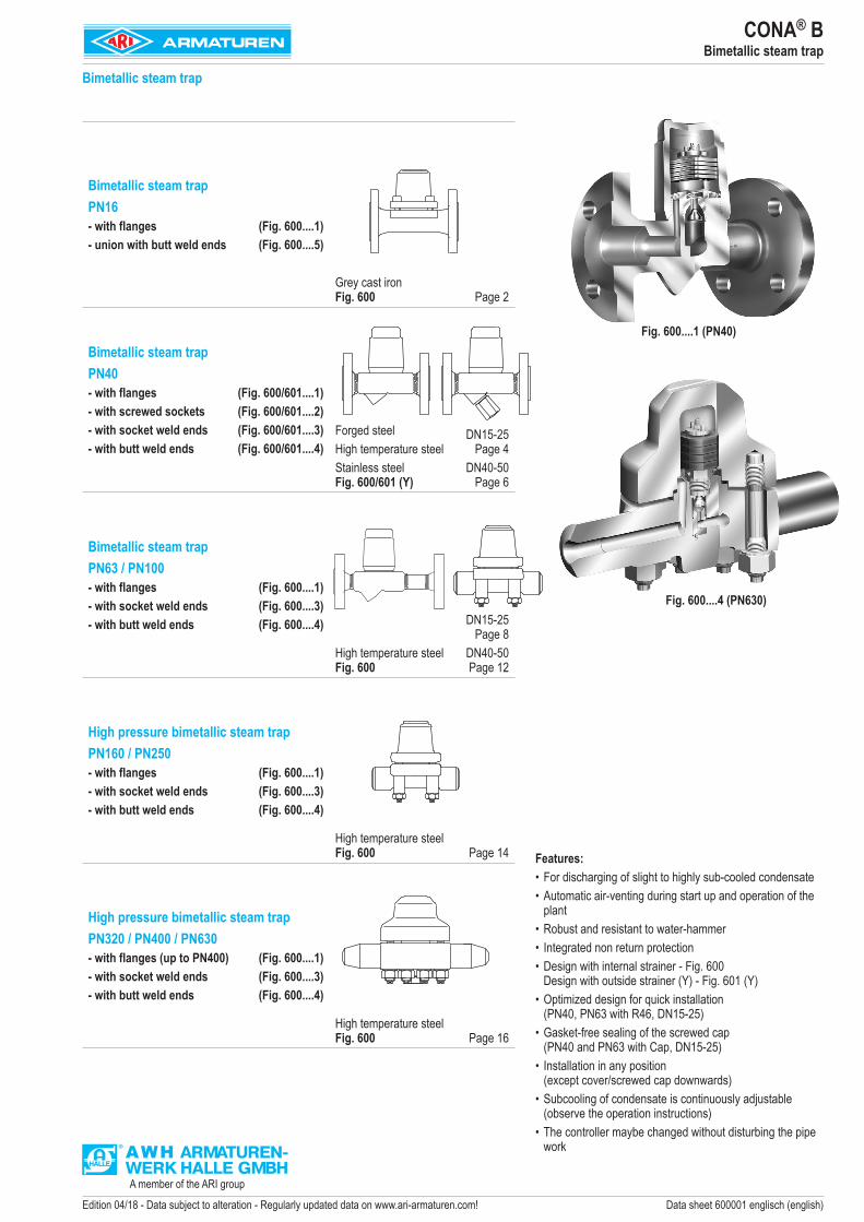
Bimetallic steam trap PN16- with flanges (Fig. 600....1)- union with butt weld ends (Fig. 600....5)
Grey cast iron Fig. 600 Page 2
Bimetallic steam trap PN40- with flanges (Fig. 600/601....1)- with screwed sockets (Fig. 600/601....2)- with socket weld ends (Fig. 600/601....3)- with butt weld ends (Fig. 600/601....4)
Forged steelHigh temperature steelStainless steel Fig. 600/601 (Y)
DN15-25 Page 4
DN40-50 Page 6
Bimetallic steam trap PN63 / PN100- with flanges (Fig. 600....1)- with socket weld ends (Fig. 600....3)- with butt weld ends (Fig. 600....4)
High temperature steelFig. 600
DN15-25 Page 8
DN40-50 Page 12
High pressure bimetallic steam trap PN160 / PN250- with flanges (Fig. 600....1)- with socket weld ends (Fig. 600....3)- with butt weld ends (Fig. 600....4)
High temperature steelFig. 600 Page 14
High pressure bimetallic steam trap PN320 / PN400 / PN630- with flanges (up to PN400) (Fig. 600....1)- with socket weld ends (Fig. 600....3)- with butt weld ends (Fig. 600....4)
High temperature steelFig. 600 Page 16
CONA® BBimetallic steam trap
Features: •For discharging of slight to highly sub-cooled condensate • Automatic air-venting during start up and operation of the
plant•Robust and resistant to water-hammer• Integrated non return protection• Design with internal strainer - Fig. 600
Design with outside strainer (Y) - Fig. 601 (Y)• Optimized design for quick installation
(PN40, PN63 with R46, DN15-25)• Gasket-free sealing of the screwed cap
(PN40 and PN63 with Cap, DN15-25)• Installation in any position
(except cover/screwed cap downwards)• Subcooling of condensate is continuously adjustable
(observe the operation instructions)• The controller maybe changed without disturbing the pipe
work
Fig. 600....1 (PN40)
Fig. 600....4 (PN630)
Bimetallic steam trap

2 Edition 04/18 - Data subject to alteration - Regularly updated data on www.ari-armaturen.com!
Figure Nominal pressure Material Nominal
diameter / NPSOperating pressure
PSInlet temperature
TSallowable differential
pressure ΔPMXfor
controller
12.600 PN16 EN-JL1040 DN15-50 / 1/2" - 2"
12,8 barg 200 °C13 bar R13
9,6 barg 300 °C
For ANSI versions refer to data sheet CONA®B-ANSI
Types of connection Other types of connection on request.• Flanges ....1 _______________acc. to DIN EN 1092-2• Union butt weld nipples ....5 __acc. to data sheet resp. customer requestFeatures • Thermostatic steam trap with non-corrosive and robust water hammer proof bimetallic controller• Automatic air-venting during start up and operation of the plant• Non return protection• With inside strainer• Installation in any position, except cover downwards• Subcooling of condensate is continuously adjustable (observe the operation instructions)Controller (chooseable for operating range)
• Controller R13 _____________up to inlet pressure: 13 bar
CONA®B 600 PN16 - DN15-50
Bimetallic steam trap (Grey cast iron)
Fig. 600....1 with inside strainer
Fig. 600....5 union with butt weld ends

3Edition 04/18 - Data subject to alteration - Regularly updated data on www.ari-armaturen.com!
Types of connection Flanges Union butt weld nipples
DN 25 50 15 20NPS 1" 2" 1/2" 3/4"
Face-to-face acc. to data sheet resp. customer requestL (mm) 160 230 190 190
Dimensions Standard-flange dimensions refer to page 19 / Larger nominal diameters refer to page 4.H (mm) 100 124 100 100S (mm) 70 90 70 70SQR (mm) 85 105 85 85
Weights Fig. 600 (approx.) (kg) 4,6 10 2,6 2,3
PartsPos. Sp.p. Description Fig. 12.6001 Body EN-GJL-250, EN-JL10402 x Strainer X5CrNi18-10, 1.43016 Cover EN-GJL-250, EN-JL104011 x Sealing ring CU14 Union nut 11SMn30+C, 1.0715+C15 Welding end C15, 1.040123 x Sealing ring Novapress MULTI24 x Controller, cpl. TB 102 / 85 (corrosion resistant bimetal)26 x Gasket Graphite (CrNi laminated with graphite)27 Cheese head screw A2-70
└Spareparts
Information / restriction of technical rules need to be observed! Resistance and fitness must be verified (contact manufacturer for information, refer to Product overview and Resistance list).Operating and installation instructions can be downloaded at www.ari-armaturen.com.
Capacity chart
The capacity chart shows the maximum capacity at factory setting. (Other factory-settings for the sub-cooling on request.)Curve 1: Maximum flow of hot condensate at approx. 10 K below saturation temperature.Curve 2: Maximum flow of sub-cooled condensate at approx. 30 K below saturation temperature (with back-up of condensate).Curve 3: Maximum flow at cold condensate at about 20°C (during start-up of a cold installation).
CONA®B 600 PN16 - DN15-50
Flow
(kg/h)
Differential pressure considering drainage into atmosphere (bar)
4 Edition 04/18 - Data subject to alteration - Regularly updated data on www.ari-armaturen.com!
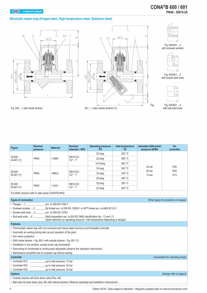
CONA®B 600 / 601 PN40 - DN15-25
Bimetallic steam trap (Forged steel, High temperature steel, Stainless steel)
Fig. 600....1 with inside strainerFig.
601....1 with outside strainer (Y)
Fig. 600/601....2 with screwed sockets
Fig. 600/601....3 with socket weld ends
Fig. 600/601....4 with butt weld ends
Figure Nominal pressure Material Nominal
diameter / NPSOperating pressure
PSInlet temperature
TSallowable differential
pressure ΔPMXfor
controller
45.600 45.601 (Y) PN40 1.0460 DN15-25 /
1/2" - 1"
32 barg 250 °C
32 bar22 bar13 bar
R32R22R13
22 barg 385 °C
14,5 barg 450 °C
85.600 85.601 (Y) PN40 16Mo3 DN15-25 /
1/2" - 1"
35 barg 300 °C
32 barg 335 °C
28 barg 450 °C
55.600 55.601 (Y) PN40 1.4541 DN15-25 /
1/2" - 1"32 barg 350 °C
22 barg 400 °C
For ANSI versions refer to data sheet CONA®B-ANSI
Types of connection Other types of connection on request.• Flanges ....1 _______________acc. to DIN EN 1092-1• Screwed sockets ....2 _______Rp thread acc. to DIN EN 10226-1 or NPT thread acc. to ANSI B1.20.1• Socket weld ends ....3 _______acc. to DIN EN 12760• Butt weld ends ....4 _________ Weld preparation acc. to EN ISO 9692 identification No. 1.3 and 1.5
(Note restriction on operating pressure / inlet temperature depending to design!)Features • Thermostatic steam trap with non-corrosive and robust water hammer proof bimetallic controller• Automatic air-venting during start up and operation of the plant• Non return protection• With inside strainer - Fig. 600 / with outside strainer - Fig. 601 (Y)• Installation in any position, except screw cap downwards• Subcooling of condensate is continuously adjustable (observe the operation instructions)• Maintenance simplified due to screwed cap without sealingController (chooseable for operating range)• Controller R13 ____________up to inlet pressure: 13 bar• Controller R22 ____________up to inlet pressure: 22 bar• Controller R32 _____________up to inlet pressure: 32 barOptions (Design refer to page 5)• Outside strainer with blow down valve (Pos. 46) • Ball valve for blow down (pos. 56) with internal strainer (Observe operating and installation instructions!)

5Edition 04/18 - Data subject to alteration - Regularly updated data on www.ari-armaturen.com!
Types of connection Flanges Screwed sockets Socket weld ends Butt weld ends
DN 15 20 25 15 20 25 15 20 25NPS 1/2" 3/4" 1" 1/2" 3/4" 1" 1/2" 3/4" 1"
Face-to-face acc. to data sheet resp. customer requestL (mm) 150 150 160 95 95 95 250 250 250
Dimensions Standard-flange dimensions refer to page 19 / Larger nominal diameters refer to page 6.H (mm) 98 98 98 98 98 103 98 98 98H1 (mm) 62 62 62 62 62 55 62 62 62S (mm) 70 70 70 70 70 70 70 70 70S1 (mm) 30 30 30 30 30 30 30 30 30HEX (mm) 50 50 50 50 50 50 50 50 50
Weights Fig. 600 / 601 (approx.) (kg) 3,2 3,7 4,2 1,7 1,6 2,1 2,2 2,3 2,4
PartsPos. Sp.p. Description Fig. 45.600 / 45.601 Fig. 85.600 / 85.601 Fig. 55.600 / 55.6011 Body P250 GH, 1.0460 16Mo3, 1.5415 X6CrNiTi18-10, 1.45412 x Strainer X5CrNi18-10, 1.43016 Cap P250 GH, 1.0460 16Mo3, 1.5415 X6CrNiTi18-10, 1.45417 x Strainer X5CrNi18-10, 1.43018 x Strainer plug X6CrNiTi18-10, 1.454124 x Controller, cpl. TB 102 / 85 (corrosion resistant bimetal)46 x Blow down valve, cpl. X6CrNiTi18-10, 1.454156 x Ball valve for blow down (G 3/8”) GX5CrNiMo19-11-2, 1.4408
└Spareparts
Information / restriction of technical rules need to be observed! Resistance and fitness must be verified (contact manufacturer for information, refer to Product overview and Resistance list).Operating and installation instructions can be downloaded at www.ari-armaturen.com.
Capacity chart
The capacity chart shows the maximum capacity at factory setting. (Other factory-settings for the sub-cooling on request.)Curve 1: Maximum flow of hot condensate at approx. 10 K below saturation temperature.Curve 2: Maximum flow of sub-cooled condensate at approx. 30 K below saturation temperature (with back-up of condensate).Curve 3: Maximum flow at cold condensate at about 20°C (during start-up of a cold installation).The condensate temperature determines the opening of the controller. Capacity is increased with the sub-cooling temperature of the condensate.
CONA®B 600 / 601 PN40 - DN15-25
Flow
(kg/h)
Differential pressure considering drainage into atmosphere (bar)
Flow
(kg/h)
Differential pressure considering drainage into atmosphere (bar)
Options
Outside strainer with blow down valve Ball valve with adapter for blow down with internal strainer (restricted to 13 bar, 200°C)

6 Edition 04/18 - Data subject to alteration - Regularly updated data on www.ari-armaturen.com!
CONA®B 600 / 601 PN40 - DN40-50
Bimetallic steam trap (Forged steel, High temperature steel, Stainless steel)
Fig. 600....1 with inside strainer Fig. 601....1 with outside strainer (Y)
Fig. 600/601....2 with screwed sockets
Fig. 600/601....3 with socket weld ends
Fig. 600/601....4 with butt weld ends
Figure Nominal pressure Material Nominal
diameter / NPSOperating pressure
PSInlet temperature
TSallowable differential
pressure ΔPMXfor
controller
45.600 45.601 (Y) PN40 1.0460 DN40-50 /
1 1/2" - 2"
32 barg 250 °C
32 bar 22 bar13 bar
R32R22R13
22 barg 385 °C
14,5 barg 450 °C
85.600 85.601 (Y) PN40 16Mo3 DN40-50 /
1 1/2" - 2"
35 barg 300 °C
32 barg 335 °C
28 barg 450 °C
55.600 55.601 (Y) PN40 1.4541 DN40-50 /
1 1/2" - 2"32 barg 350 °C
22 barg 400 °C
For ANSI versions refer to data sheet CONA®B-ANSI
Types of connection Other types of connection on request.• Flanges ....1 _______________acc. to DIN EN 1092-1• Screwed sockets ....2 _______Rp thread acc. to DIN EN 10226-1 or NPT thread acc. to ANSI B1.20.1• Socket weld ends ....3 _______acc. to DIN EN 12760• Butt weld ends ....4 _________ Weld preparation acc. to EN ISO 9692 identification No. 1.3 and 1.5
(Note restriction on operating pressure / inlet temperature depending to design!)Features •Thermostaticsteamtrapwithnon-corrosiveandrobustwaterhammerproofbimetalliccontroller•Automaticair-ventingduringstartupandoperationoftheplant•Nonreturnprotection•Withinsidestrainer-Fig.600/withoutsidestrainer-Fig.601(Y)•Installationinanyposition,exceptcoverdownwards•Subcoolingofcondensateiscontinuouslyadjustable(observetheoperationinstructions)Controller (chooseable for operating range)• Controller R13 ____________up to inlet pressure: 13 bar• Controller R22 _____________up to inlet pressure: 22 bar• Controller R32 _____________up to inlet pressure: 32 barOptions (Design refer to page 5)• Outside strainer with blow down valve (Pos. 46) • Ball valve for blow down (pos. 56) with internal strainer (Observe operating and installation instructions!)

7Edition 04/18 - Data subject to alteration - Regularly updated data on www.ari-armaturen.com!
CONA®B 600 / 601 PN40 - DN40-50
Capacity chart
The capacity chart shows the maximum capacity at factory setting. (Other factory-settings for the sub-cooling on request.)Curve 1: Maximum flow of hot condensate approx. 15 K below saturation
temperature.Curve 2: Maximum flow of sub-cooled condensate at approx. 30 K below saturation
temperature (with back-up of condensate).Curve 3: Maximum flow at cold condensate at about 20°C
(during start-up of a cold installation).The condensate temperature determines the opening of the controller. Capacity is increased with the sub-cooling temperature of the condensate.
Options
Outside strainer with blow down valve Ball valve with adapter for blow down with internal strainer (restricted to 13 bar, 200°C)
Types of connection Flanges Screwed sockets Socket weld ends Butt weld ends
DN 40 50 40 50 40 50
NPS 1 1/2" 2" 1 1/2" 2" 1 1/2" 2"
Face-to-face acc. to data sheet resp. customer request
L (mm) 230 230 130 / 160 1) 210 250 2501) Construction with screwed sockets
Dimensions Standard-flange dimensions refer to page 19 H (mm) 144 144 144 144 144 144H1 (mm) 68 68 68 68 68 68S (mm) 90 90 90 90 90 90S1 (mm) 50 50 50 50 50 50SQR (mm) 110 110 110 110 110 110
Weights Fig. 600 / 601 (approx.) (kg) 11,3 12,1 8 8 8,9 9,8
PartsPos. Sp.p. Description Fig. 45.600 / 45.601 Fig. 85.600 / 85.601 Fig. 55.600 / 55.6011 Body P250 GH, 1.0460 16Mo3, 1.5415 X6CrNiTi18-10, 1.45412 x Strainer X5CrNi18-10, 1.43016 Cover P250 GH, 1.0460 16Mo3, 1.5415 X6CrNiTi18-10, 1.45417 x Strainer X5CrNi18-10, 1.43018 x Strainer plug X6CrNiTi18-10, 1.454124 x Controller, cpl. TB 102 / 85 (corrosion resistant bimetal)26 x Gasket Graphite (CrNi laminated with graphite)27 Cheese head screw 21CrMoV 5-7, 1.770946 x Blow down valve, cpl. X6CrNiTi18-10, 1.454156 x Ball valve for blow down (G 3/8”) GX5CrNiMo19-11-2, 1.4408
└SparepartsInformation / restriction of technical rules need to be observed! Resistance and fitness must be verified (contact manufacturer for information, refer to Product overview and Resistance list).Operating and installation instructions can be downloaded at www.ari-armaturen.com.
Flow
(kg/h)
Differential pressure considering drainage into atmosphere (bar)

8 Edition 04/18 - Data subject to alteration - Regularly updated data on www.ari-armaturen.com!
CONA®B 600 PN63 - DN15-25
Bimetallic steam trap (High temperature steel)
Fig. 600....1 with inside strainer
Fig. 600....3 with socket weld ends
Fig. 600....4 with butt weld ends
Figure Nominal pressure Material Nominal
diameter / NPSOperating pressure
PSInlet temperature
TSallowable differential
pressure ΔPMXfor
controller
86.600 PN63 16Mo3 DN15-25 / 1/2" - 1"
46 barg 425 °C46 bar R46
45 barg 450 °C
For ANSI versions refer to data sheet CONA®B-ANSI
Types of connection Other types of connection on request.• Flanges ....1 _______________acc. to DIN EN 1092-1• Socket weld ends ....3 _______acc. to DIN EN 12760• Butt weld ends ....4 _________ Weld preparation acc. to EN ISO 9692 identification No. 1.3 and 1.5
(Note restriction on operating pressure / inlet temperature depending to design!)Features • Thermostatic steam trap with non-corrosive and robust water hammer proof bimetallic controller• Automatic air-venting during start up and operation of the plant• Non return protection• With inside strainer • Installation in any position, except screw cap downwards• Subcooling of condensate is continuously adjustable (observe the operation instructions)• Maintenance simplified due to screwed cap without sealingController (chooseable for operating range)
• Controller R46 _____________up to inlet pressure: 46 bar

9Edition 04/18 - Data subject to alteration - Regularly updated data on www.ari-armaturen.com!
Types of connection Flanges Socket weld ends Butt weld ends 1)
DN 15 20 25 15 20 25 15 20 25
NPS 1/2" 3/4" 1" 1/2" 3/4" 1" 1/2" 3/4" 1"1) Please indicate dimension of the tube when orderingFace-to-face acc. to data sheet resp. customer request
L (mm) 210 210 230 95 95 95 250 250 250
Dimensions Standard-flange dimensions refer to page 19
H (mm) 98 98 98 98 98 103 98 98 98
S (mm) 70 70 70 70 70 70 70 70 70
HEX (mm) 50 50 50 50 50 50 50 50 50
Weights
Fig. 600 (approx.) (kg) 4,1 5,6 7 1,7 1,6 2,1 2,2 2,3 2,4
Parts
Pos. Sp.p. Description Fig. 86.600
1 Body 16Mo3, 1.5415
2 x Strainer X5CrNi18-10, 1.4301
6 Cap 16Mo3, 1.5415
24 x Controller, cpl. TB 102 / 85 (corrosion resistant bimetal)
└Spareparts
Information / restriction of technical rules need to be observed! Resistance and fitness must be verified (contact manufacturer for information, refer to Product overview and Resistance list).Operating and installation instructions can be downloaded at www.ari-armaturen.com.
Capacity chart
The capacity chart shows the maximum capacity at factory setting. (For operating pressures below 5 bar, a correction of the factory-setting acc. to manufacturers information is recommended.)Curve 1: Maximum flow of hot condensate approx. 15 K below saturation temperature.Curve 2: Maximum flow of sub-cooled condensate at approx. 30 K below saturation temperature (with back-up of condensate).Curve 3: Maximum flow at cold condensate at about 20°C (during start-up of a cold installation).The condensate temperature determines the opening of the controller. Capacity is increased with the sub-cooling temperature of the condensate.
CONA®B 600 PN63 - DN15-25
Flow
(kg/h)
Differential pressure considering drainage into atmosphere (bar)

10 Edition 04/18 - Data subject to alteration - Regularly updated data on www.ari-armaturen.com!
CONA®B 600 PN63 / PN100 - DN15-25
High pressure - Bimetallic steam trap (High temperature steel)
Fig. 600....4 with butt weld ends
Fig. 600....1 with flanges
Fig. 600....3 with socket weld ends
Figure Nominal pressure Material Nominal
diameter / NPSOperating pressure
PSInlet temperature
TSallowable differential
pressure ΔPMXfor
controller
86.600 PN63 16Mo3 DN15-25 / 1/2" - 1"
56 barg 300 °C
56 bar R5647 barg 400 °C
45 barg 450 °C
87.600 PN100 16Mo3 DN15-25 / 1/2" - 1"
90 barg 450 °C56 bar 90 bar
R56 R90
56 barg 500 °C
27 barg 530 °C
For ANSI versions refer to data sheet CONA®B-ANSI
Types of connection Other types of connection on request.• Flanges ....1 _______________acc. to DIN EN 1092-1• Socket weld ends ....3 _______acc. to DIN EN 12760• Butt weld ends ....4 _________ Weld preparation acc. to EN ISO 9692 identification No. 1.3 and 1.5
(Note restriction on operating pressure / inlet temperature depending to design!)Features • Thermostatic steam trap with non-corrosive and robust water hammer proof bimetallic controller• Steam trap specially for high pressures• Automatic air-venting during start up and operation of the plant• Non return protection• With inside strainer• Installation in any position, except cover downwards• Subcooling of condensate is continuously adjustable (observe the operation instructions)• The controller maybe changed without disturbing the pipe workController (chooseable for operating range)• Controller R56 up to inlet pressure: 56 bar• Controller R90 up to inlet pressure: 90 bar

11Edition 04/18 - Data subject to alteration - Regularly updated data on www.ari-armaturen.com!
Types of connection Flanges Socket weld ends Butt weld ends 1)
DN 15 20 25 15 20 25 15 20 25
NPS 1/2" 3/4" 1" 1/2" 3/4" 1" 1/2" 3/4" 1"1) Please indicate dimension of the tube when orderingFace-to-face acc. to data sheet resp. customer request
L (mm) 210 210 230 160 160 160 160 160 160
Dimensions Standard-flange dimensions refer to page 19 / Larger nominal diameters (PN63) refer to page 12.
H (mm) 104 104 104 104 104 104 104 104 104
H1 (mm) 42 42 42 42 42 42 42 42 42
S (mm) 70 70 70 70 70 70 70 70 70
SQR (mm) 90 90 90 90 90 90 90 90 90
Weights
Fig. 600 (approx.) (kg) 6,2 7,7 9,3 4,6 4,5 4,4 4,6 4,5 4,4
Parts
Pos. Sp.p. Description Fig. 86.600 / 87.600
1 Body 16Mo3, 1.5415
2 x Strainer X5CrNi18-10, 1.4301
6 Cover 16Mo3, 1.5415
24 x Controller, cpl. TB 102 / 85 (corrosion resistant bimetal)
26 x Gasket Graphite (CrNi laminated with graphite)
28 Hexagonal nut 21CrMoV 5-7, 1.7709
29 x Erosion deflector X8CrNiS18-9, 1.4305
30 Extension sleeve 21CrMoV 5-7, 1.7709
36 Stud 21CrMoV 5-7, 1.7709
└SparepartsInformation / restriction of technical rules need to be observed! Resistance and fitness must be verified (contact manufacturer for information, refer to Product overview and Resistance list). Operating and installation instructions can be downloaded at www.ari-armaturen.com.
Capacity chart
ss
The capacity chart shows the maximum flow at factory setting. (For operating pressures below 5 bar, a correction of the factory-setting acc. to manufacturers information is recommended.)Curve 1: Maximum flow of hot condensate approx. 15 K below saturation temperature.Curve 2: Maximum flow of sub-cooled condensate at approx. 30 K below saturation temperature (with back-up of condensate).Curve 3: Maximum flow at cold condensate at about 20°C (during start-up of a cold installation).The condensate temperature determines the opening of the controller. Capacity is increased with the sub-cooling temperature of the condensate.
CONA®B 600 PN63 / PN100 - DN15-25
Flow
(kg/h)
Differential pressure considering drainage into atmosphere (bar)

12 Edition 04/18 - Data subject to alteration - Regularly updated data on www.ari-armaturen.com!
CONA®B 600 PN63 - DN40-50
High pressure - Bimetallic steam trap (High temperature steel)
Fig. 600....1 with flanges
Fig. 600....3 with socket weld ends
Fig. 600....4 with butt weld ends
Figure Nominal pressure Material Nominal
diameter / NPSOperating pressure
PSInlet temperature
TSallowable differential
pressure ΔPMXfor
controller
86.600 PN63 16Mo3 DN40-50 / 1 1/2" - 2"
56 barg 300 °C56 bar32 bar
R56R32
50 barg 350 °C
45 barg 450 °C
For ANSI versions refer to data sheet CONA®B-ANSI
Types of connection Other types of connection on request.• Flanges ....1 _______________acc. to DIN EN 1092-1• Socket weld ends ....3 _______acc. to DIN EN 12760• Butt weld ends ....4 _________ Weld preparation acc. to EN ISO 9692 identification No. 1.3 and 1.5
(Note restriction on operating pressure / inlet temperature depending to design!)Features • Thermostatic steam trap with non-corrosive and robust water hammer proof bimetallic controller• Automatic air-venting during start up and operation of the plant• Non return protection• With inside strainer• Installation in any position, except cover downwards• Subcooling of condensate is continuously adjustable (observe the operation instructions)• The controller maybe changed without disturbing the pipe workController (chooseable for operating range)• Controller R56 ____________up to inlet pressure: 56 bar• Controller R32 ____________up to inlet pressure: 32 bar

13Edition 04/18 - Data subject to alteration - Regularly updated data on www.ari-armaturen.com!
Types of connection Flanges Socket weld ends Butt weld ends 1)
DN 40 50 40 50 40 50
NPS 1 1/2" 2" 1 1/2" 2" 1 1/2" 2"1) Please indicate dimension of the tube when ordering
Face-to-face acc. to data sheet resp. customer request
L (mm) 260 300 130 210 250 250
Dimensions Standard-flange dimensions refer to page 19 / Smaller nominal diameters refer to page 10
H (mm) 144 144 144 144 144 144
S (mm) 90 90 90 90 90 90
SQR (mm) 110 110 110 110 110 110
Weights
Fig. 600 (approx.) (kg) 13,3 14,1 8 8 8,9 9,8
Parts
Pos. Sp.p. Description Fig. 86.600
1 Body 16Mo3, 1.5415
2 x Strainer X5CrNi18-10, 1.4301
6 Cover 16Mo3, 1.5415
24 x Controller, cpl. TB 102 / 85 (corrosion resistant bimetal)
26 x Gasket Graphite (CrNi laminated with graphite)
28 Hexagonal nut 21CrMoV 5-7, 1.7709
30 Extension sleeve 21CrMoV 5-7, 1.7709
36 Stud 21CrMoV 5-7, 1.7709
└Spareparts
Information / restriction of technical rules need to be observed! Resistance and fitness must be verified (contact manufacturer for information, refer to Product overview and Resistance list).Operating and installation instructions can be downloaded at www.ari-armaturen.com.
Capacity chart
The capacity chart shows the maximum flow at factory setting. (For operating pressures below 5 bar, a correction of the factory-setting acc. to manufacturers information is recommended.)Curve 1: Maximum flow of hot condensate approx. 15 K below saturation temperature.Curve 2: Maximum flow of sub-cooled condensate at approx. 30 K below saturation temperature (with back-up of condensate).Curve 3: Maximum flow at cold condensate at about 20°C (during start-up of a cold installation).The condensate temperature determines the opening of the controller. Capacity is increased with the sub-cooling temperature of the condensate.
CONA®B 600 PN63 - DN40-50
Flow
(kg/h)
Differential pressure considering drainage into atmosphere (bar)

14 Edition 04/18 - Data subject to alteration - Regularly updated data on www.ari-armaturen.com!
CONA®B 600 PN160 / PN250 - DN15-25
High pressure - Bimetallic steam trap (High temperature steel)
Fig. 600....4 with butt weld ends
Fig. 600....1 with flanges
Fig. 600....3 with socket weld ends
Figure Nominal pressure Material Nominal
diameter / NPSOperating pressure
PSInlet temperature
TSallowable differential
pressure ΔPMXfor
controller
88.600 PN160 13CrMo4-5 DN15-25 / 1/2" - 1"
153 barg 350 °C
110 bar R130100 barg 510 °C
62 barg 530 °C
35 barg 550 °C
89.600 PN250 10CrMo9-10 DN15-25 / 1/2" - 1"
184 barg 500 °C
154 bar R150154 barg 510 °C
108 barg 530 °C
81 barg 550 °C
For ANSI versions refer to data sheet CONA®B-ANSI
Types of connection Other types of connection on request.• Flanges ....1 _______________acc. to DIN EN 1092-1• Socket weld ends ....3 _______acc. to DIN EN 12760• Butt weld ends ....4 _________ Weld preparation acc. to EN ISO 9692 identification No. 1.3 and 1.5
(Note restriction on operating pressure / inlet temperature depending to design!)Features • Thermostatic steam trap with non-corrosive and robust water hammer proof bimetallic controller• Steam trap specially for high pressures• Automatic air-venting during start up and operation of the plant• Non return protection• With inside strainer• Installation in any position, except cover downwards• Subcooling of condensate is continuously adjustable (observe the operation instructions)• The controller maybe changed without disturbing the pipe workController (chooseable for operating range)• Controller R130 ___________up to inlet pressure: 110 bar• Controller R150 ___________up to inlet pressure: 154 bar

15Edition 04/18 - Data subject to alteration - Regularly updated data on www.ari-armaturen.com!
Types of connection Flanges Socket weld ends Butt weld ends 1) DN 15 25 15 20 25 15 20 25NPS 1/2" 1" 1/2" 3/4" 1" 1/2" 3/4" 1" 1) Please indicate dimension of the tube when orderingFace-to-face acc. to data sheet resp. customer requestL (mm) 210 230 160 160 160 160 160 160
Dimensions Standard-flange dimensions refer to page 19H (mm) 104 104 104 104 104 104 104 104H1 (mm) 42 42 42 42 42 42 42 42S (mm) 70 70 70 70 70 70 70 70SQR (mm) 90 90 90 90 90 90 90 90
Weights Fig. 600 (approx.) (kg) 6,4 9,6 4,8 4,7 4,6 4,8 4,7 4,6
Parts
Pos. Sp.p. Description Fig. 88.600 Fig. 89.600
1 Body 13CrMo4-5, 1.7335 10CrMo9-10, 1.7380
2 x Strainer X5CrNi18-10, 1.4301
6 Cover 13CrMo4-5, 1.7335 10CrMo9-10, 1.7380
24 x Controller, cpl. TB 102 / 85 (corrosion resistant bimetal)
26 x Gasket Graphite (CrNi laminated with graphite)
28 Hexagonal nut 21CrMoV 5-7, 1.7709 X22CrMoV12-1, 1.4923
29 x Erosion deflector X8CrNiS18-9, 1.4305
30 Extension sleeve 21CrMoV 5-7, 1.7709 X22CrMoV12-1, 1.4923
32 x Clamping sleeve X39CrMo17-1+QT, 1.4122+QT
36 Stud 21CrMoV 5-7, 1.7709 X22CrMoV12-1, 1.4923
└Spareparts
Information / restriction of technical rules need to be observed! Resistance and fitness must be verified (contact manufacturer for information, refer to Product overview and Resistance list).Operating and installation instructions can be downloaded at www.ari-armaturen.com.
Capacity chart
Capacity chart PN160 Capacity chart PN250The capacity chart shows the maximum capacity at factory setting. (For operating pressures below 15 bar, a correction of the factory-setting acc. to manufacturers information is recommended.)Curve 1: Maximum flow of hot condensate at approx. 10 K below saturation temperature.Curve 2: Maximum flow of sub-cooled condensate at approx. 30 K below saturation temperature (with back-up of condensate).Curve 3: Maximum flow at cold condensate at about 20°C (during start-up of a cold installation).The condensate temperature determines the opening of the controller. Capacity is increased with the sub-cooling temperature of the condensate.
CONA®B 600 PN160 / PN250 - DN15-25
Flow
(kg/h)
Differential pressure considering drainage into atmosphere (bar)
Flow
(kg/h)
Differential pressure considering drainage into atmosphere (bar)

16 Edition 04/18 - Data subject to alteration - Regularly updated data on www.ari-armaturen.com!
CONA®B 600 PN320 / PN400 / PN630 - DN15-25
High pressure - Bimetallic steam trap (High temperature steel)
Fig. 600....4 with butt weld ends
Fig. 600....1 (PN320 / 400, 1.7380) with flanges
Fig. 600....3 with socket weld ends
Figure Nominal pressure Material Nominal
diameter / NPSOperating pressure
PSInlet temperature
TSallowable differential
pressure ΔPMXfor
controller
8a.600 PN320 10CrMo9-10, 1.7380
DN15-25 / 1/2" - 1"
200 barg 510 °C
200 bar R270139 barg 530 °C121 barg 540 °C104 barg 550 °C
8b.600 PN400 10CrMo9-10, 1.7380
DN15-25 / 1/2" - 1"
250 barg 510 °C
250 bar R270174 barg 530 °C151 barg 540 °C130 barg 550 °C
8c.600 PN630
10CrMo9-10, 1.7380
DN15-25 / 1/2" - 1"
270 barg 547 °C
270 bar R270
250 barg 550 °C216 barg 560 °C162 barg 580 °C
X10CrMo VNb9-1, 1.4903
DN15-25 / 1/2" - 1"
298 barg 550 °C270 barg 581 °C205 barg 590 °C130 barg 600 °C
X10CrWMo VNb9-2, 1.4901
DN15-25 / 1/2" - 1"
320 barg 600 °C
320 bar R320300 barg 610 °C220 barg 630 °C160 barg 650 °C
For ANSI versions refer to data sheet CONA®B-ANSI
Types of connection Other types of connection on request.• Flanges ....1 _______________acc. to DIN EN 1092-1 (only for material 1.7380)• Socket weld ends ....3 _______acc. to DIN EN 12760• Butt weld ends ....4 _________ Weld preparation acc. to EN ISO 9692 identification No. 1.3 and 1.5
(Note restriction on operating pressure / inlet temperature depending to design!)Features • Thermostatic steam trap with non-corrosive and robust water hammer proof bimetallic controller• Steam trap specially for high pressures• Automatic air-venting during start up and operation of the plant• Non return protection• With inside strainer• Installation in any position, except cover downwards• Subcooling of condensate is continuously adjustable (observe the operation instructions)• The controller maybe changed without disturbing the pipe workController (chooseable for operating range)• Controller R270 ___________up to inlet pressure: 270 bar (or to 200 bar at PN320; 250 bar at PN 400)• Controller R320 ___________up to inlet pressure: 320 bar

17Edition 04/18 - Data subject to alteration - Regularly updated data on www.ari-armaturen.com!
Types of connection Flanges1) Socket weld ends Butt weld ends 2)
DN 15 25 15 20 25 15 20 25NP 1/2" 1" 1/2" 3/4" 1" 1/2" 3/4" 1"1) only for material 1.7380 2) Please indicate dimension of the tube when orderingFace-to-face acc. to data sheet resp. customer requestL (mm) 435 470 330 330 330 330 330 330
Dimensions Standard-flange dimensions refer to page 19H (mm) 142 142 142 142 142 142 142 142H1 (mm) 63 63 63 63 63 63 63 63S (mm) 95 95 95 95 95 95 95 95A (mm) 155 155 155 155 155 155 155 155
Weights Fig. 600 (approx.) (kg) 27 33 20 20 19 20 20 19
Parts
Pos. Sp.p. Description Fig. 8a.600 / 8b.600 / 8c.600 Fig. 8c.600 Fig. 8c.600
1 Body 10CrMo9-10, 1.7380 X10CrMoVNb9-1, 1.4903 X10CrWMoVNb9-2, 1.4901
2 x Strainer X5CrNi18-10, 1.4301
6 Cover 10CrMo9-10, 1.7380 X10CrMoVNb9-1, 1.4903 X10CrWMoVNb9-2, 1.4901
24 x Controller, cpl. TB 102 / 85 (corrosion resistant bimetal)
26 x Spiral gasket MICA/RGF (CrNi laminated with graphite)
28 Hexagonal nut X22CrMoV12-1, 1.4923 X7CrNiMoBNb16-16, 1.4986
36 Stud X22CrMoV12-1, 1.4923 X7CrNiMoBNb16-16, 1.4986
94
x Erosion deflector X39CrMo17-1+QT, 1.4122+QT
x Clamping sleeve X39CrMo17-1+QT, 1.4122+QT
x Taper pin A2
└Spareparts
Information / restriction of technical rules need to be observed! Resistance and fitness must be verified (contact manufacturer for information, refer to Product overview and Resistance list).Operating and installation instructions can be downloaded at www.ari-armaturen.com.
Capacity chart
The capacity chart shows the maximum capacity at factory setting. (For operating pressures below 15 bar, a correction of the factory-setting acc. to manufacturers information is recommended.)Curve 1: Maximum flow of hot condensate at approx. 10 K below saturation temperature.Curve 2: Maximum flow of sub-cooled condensate at approx. 30 K below saturation temperature (with back-up of condensate).Curve 3: Maximum flow at cold condensate at about 20°C (during start-up of a cold installation).The condensate temperature determines the opening of the controller. Capacity is increased with the sub-cooling temperature of the condensate.
CONA®B 600 PN320 / PN400 / PN630 - DN15-25
Flow
(kg/h)
Differential pressure considering drainage into atmosphere (bar)
Flow
(kg/h)
Differential pressure considering drainage into atmosphere (bar)

18 Edition 04/18 - Data subject to alteration - Regularly updated data on www.ari-armaturen.com!
ARI-myValve®Valve SIzing-Program
myValve® - Your VAlve SIzing-Program.myValve is a powerful software tool that not only helps you size your system components; it also gives you instant access to all other data about the selected product, such as order information, spare parts drawings, operating instructions, data sheets, etc., whenever you need it.
myValve - VAlve SIzing-ProgramContents: Module ARI-Steam trap CONA-Calcuation
- Sizing (calculation of steam trap systems with given flow capacity or heat capacity)- Calculation of nominal diameter acc. to given pressure, condensate quantity, condensate sub-cooling and speed
Media: - Steam (saturated and superheated)- Compressed air
Special Features - Project administration of the calculation and product data incl. spare part drawings concerning to project and tag number - Direct output or calculation and product data in PDF format - Product data could be taken for a direct order - SI- and ANSI-units with direct conversion to another databank - Settings with over pressure or absolute pressure - All ARI products are integrated in one databank - Direct access concerning to the product on data sheets, operating instructions, pressure-temperature-diagram and spare part
drawings - Operation in company networks possible (no complex installations on individually PC‘s necessary) - Extensive catalogue extending over several product groups
System Requirements: Windows operating systems, Linux, etc.

19Edition 04/18 - Data subject to alteration - Regularly updated data on www.ari-armaturen.com!
CONA®B Informations about pipe welding / Standard-flange dimensions
Informations about pipe weldingWelding groove acc. to DIN 2559The material used for ARI valves with butt weld ends are: 1.0619+N GP240GH+N acc. to DIN EN 10213-2
1.0460 P250GH acc. to DIN EN 10222-2 1.0401 C15 acc. to DIN EN 10277-2
Note: Note restriction on operating pressure / inlet temperature depending to design!
1.5415 16Mo3 acc. to DIN EN 10222-21.4541 X6CrNiTi18-10 acc. to DIN EN 10222-51.7335 13CrMo4-5 acc. to DIN EN 10222-21.7380 10CrMo 9-10 acc. to DIN EN 17243 1.4903 X10CrMoVNb 91 acc. to DIN EN 10222-21.4901 X10CrWMoVNb9-2, 1.4901 acc. to VdTÜV Data sheet 552/3
Due to our experience, we recommend to apply an electric welding process.Because of the different material compositions and wall thickness of the steam traps and the pipe gas welding shall not be applied. Quenching cracks and coarse grain structure may develop.On bimetallic steam traps face-to-face of 95 mm or less, the bimetallic controller has to be disassembled prior to welding. After the traps have cooled down to the ambient temperature the bimetallic controller shall be fitted again into the body.Steam traps with socket-weld ends shall only be welded by arc welding (welding process 111 acc. to DIN EN 24063).If during the time of warranty others than the manufacturer or by the manufacturer authorized persons are interfering in the product and/or the setting, the right of claim for warranty will lapse! Standard-flange dimensions acc. to DIN EN 1092-1 / -2DN 15 20 25 32 40 50NPS 1/2" 3/4" 1" 1 1/4" 1 1/2" 2"
PN16ØD (mm) 95 105 115 140 150 165ØK (mm) 65 75 85 100 110 125n x Ød (mm) 4 x 14 4 x 14 4 x 14 4 x 18 4 x 18 4 x 18
PN40ØD (mm) 95 105 115 140 150 165ØK (mm) 65 75 85 100 110 125n x Ød (mm) 4 x 14 4 x 14 4 x 14 4 x 18 4 x 18 4 x 18
PN63ØD (mm) 105 130 140 -- 170 180ØK (mm) 75 90 100 -- 125 135n x Ød (mm) 4 x 14 4 x 18 4 x 18 -- 4 x 22 4 x 22
PN100ØD (mm) 105 130 140 -- -- --ØK (mm) 75 90 100 -- -- --n x Ød (mm) 4 x 14 4 x 16 4 x 18 -- -- --
PN160ØD (mm) 105 -- 140 -- -- --ØK (mm) 75 -- 100 -- -- --n x Ød (mm) 4 x 14 -- 4 x 18 -- -- --
PN250ØD (mm) 130 -- 150 -- -- --ØK (mm) 90 -- 105 -- -- --n x Ød (mm) 4 x 18 -- 4 x 22 -- -- --
PN320ØD (mm) 130 -- 160 -- -- --ØK (mm) 90 -- 115 -- -- --n x Ød (mm) 4 x 18 -- 4 x 22 -- -- --
PN400ØD (mm) 145 -- 180 -- -- --ØK (mm) 100 -- 130 -- -- --n x Ød (mm) 4 x 22 -- 4 x 26 -- -- --
Selection criteria: Example for order data:• Steam pressure• Back pressure• Quantity of condensate• Nominal diameter / pressure
• Pipe-connection• Controller• Material• Place of service or kind
of steam consumer
Bimetallic steam trap CONA® B, Fig. 600, PN40, DN15, 1.0460, Controller R22, with flanges, Face-to-face dimension 150 mm

20 Edition 04/18 - Data subject to alteration - Regularly updated data on www.ari-armaturen.com!
Multifunction tester ARImetec®-S
Condensate collection (B = 160), steam distribution (B = 120)CODI ®S with gland packing Fig. 671/672;
CODI ®B with bellows seal, maintenance-free Fig. 675/676 Vacuum breaker
Fig. 655
Automatic air vent for liquid systems Fig. 656
Condensate discharge temperature limiter Fig. 645/647
Flow indicator Fig. 660/661
Return temperature limiter Fig. 650
Liquid drainer Fig. 665
(Further informations about the accessories can be found in the appropriate data sheets.)
CONA®B Accessories / further components
ARI-Armaturen Albert Richter GmbH & Co. KG, D-33750 Schloß Holte-Stukenbrock, Tel. +49 52 07 / 994-0, Telefax +49 52 07 / 994-158 or 159 Internet: http://www.ari-armaturen.com E-mail: [email protected]
Technology for the Future. G E R M A N Q U A L I T Y V A L V E S
I9001ISO
§19WHG
Q
UA
L IT Y M A N AG E M
EN
T
S Y S T E MS
AWH ARMATUREN-�WERK HALLE GMBH
®
HALLE
A member of the ARI group