halogen light source with rs232 intensity control hl...
TRANSCRIPT
000-00000-000-02-A
Halogen Light Source with RS232 Intensity Control
HL-2000-HP-232
Installation and Operation Manual Document Number 000-10000-140-02-201307
Offices: Ocean Optics, Inc. World Headquarters 830 Douglas Ave., Dunedin, FL, USA 34698 Phone 727.733.2447 Fax 727.733.3962 8 a.m.– 8 p.m. (Mon-Thu), 8 a.m.– 6 p.m. (Fri) EST
Ocean Optics Mikropack Maybachstraße 11, D73760, Ostfildern, Germany Phone +49 (0)711 34 16 96-0 Fax +49 (0)711 34 16 96-85
E-mail: [email protected] (General sales inquiries)
[email protected] (Mikropack sales inquiries) [email protected] (Questions about orders) [email protected] (Technical support)

Copyright © 2009 Ocean Optics, Inc. All rights reserved. No part of this publication may be reproduced, stored in a retrieval system, or transmitted, by any means, electronic, mechanical, photocopying, recording, or otherwise, without written permission from Ocean Optics, Inc. This manual is sold as part of an order and subject to the condition that it shall not, by way of trade or otherwise, be lent, re-sold, hired out or otherwise circulated without the prior consent of Ocean Optics, Inc. in any form of binding or cover other than that in which it is published. Trademarks Microsoft, Windows, Windows 95, Windows 98, Windows Me, Windows NT, Windows 2000, Windows XP and Excel are either registered trademarks or trademarks of Microsoft Corporation. Limit of Liability Every effort has been made to make this manual as complete and as accurate as possible, but no warranty or fitness is implied. The information provided is on an “as is” basis. Ocean Optics, Inc. shall have neither liability nor responsibility to any person or entity with respect to any loss or damages arising from the information contained in this manual.

000-10000-140-02-201307 A
Important Safety Notices 1. Read all safety and operating instructions before using this equipment.
2. Use this equipment in a clean, dry environment. Place the unit away from heat sources and ensure that nothing interferes with its ventilation.
3. Do not allow objects to fall, or liquids to spill into the unit through the enclosure openings.
4. Do not use any power supply other than the type described in these instructions or as marked on the unit.
5. Do not use the unit if it is damaged in any way. Contact your dealer for repair or replacement information.
Warranty Mikropack GmbH warrants to the original user of this instrument that it shall be free of any defects resulting from faulty manufacture of this instrument for a period of 12 months from the original data of shipment.
This instrument should not be used for any Clinical or Diagnostic purposes. Data generated in these areas is not warranted in any way by Mikropack GmbH. Any defects covered by this Warranty shall be corrected either by repair or by replacement, as determined by Mikropack GmbH.
There are no warranties that extend beyond the description herein.
This Warranty is in lieu of, and excludes, any and all other warranties or representations expressed, implied, or statutory, including merchantability and fitness, as well as any and all other obligations or liabilities of Mikropack GmbH including, but not limited to, special or consequential damages. No person, firm, or corporation is authorized to assume for Mikropack GmbH. Any additional obligation or liability not expressed provided for herein except in writing duly executed by an officer of Mikropack GmbH:
MIKROPACK GmbH Maybachstraße 11 D-73760 Ostfildern Tel.: +49 (0)711 34 16 96-51 • Fax.: +49 (0)711 34 16 96-85 e-mail: [email protected] internet: www.mikropack.de

Important Safety Notices
B 000-10000-140-02-201307
000-10000-140-02-201307 i
Table of Contents
About This Manual .............................................................................................................iii
Document Purpose and Intended Audience .............................................................................. iii What’s New in this Document ................................................................................................... iii Document Summary .................................................................................................................. iii Product-Related Documentation ............................................................................................... iii
Upgrades ............................................................................................................................iv Chapter 1: Setup ................................................................................... 1
Overview .............................................................................................................................1 Setting Up the HL-2000-HP-232 Light Source ..................................................................1
Unpacking the Light Source ...................................................................................................... 1 Package Contents ..................................................................................................................... 2 Set-Up ........................................................................................................................................ 2
Chapter 2: Operation ........................................................................... 5
Optimizing the Optical Power Output .................................................................................5 Shutter Diagram .................................................................................................................6
Chapter 3: Bulb Replacement ............................................................. 7
Overview .............................................................................................................................7 Bulb Replacement Procedure ............................................................................................7
Appendix A: ASCII Commands ........................................................... 9
Motion-Related Commands ...............................................................................................9 Configuration-Related Commands ....................................................................................10 External Limit Switch Configuration Commands ...............................................................11 Commands That Return Data ............................................................................................12
Table of Contents
ii 000-10000-140-02-201307
Appendix B: HL-2000-HP-232 Specifications .................................... 15
Specifications .....................................................................................................................15 Parts List .............................................................................................................................16
Index ...................................................................................................... 17
000-10000-140-02-201307 iii
About This Manual
Document Purpose and Intended Audience This document provides you with set-up and operation information to get your light source up and running.
What’s New in this Document This version of the Halogen Light Source with RS232 Intensity Control HL-2000-HP-232 Installation and Operation Manual updates the logo and the contact information.
Document Summary Chapter Description
Chapter 1: Setup Contains a list of package contents and unpacking instructions.
Chapter 2: Operation Provides instructions for optimizing the optical power output and a diagram of the shutter.
Chapter 3: Bulb Replacement Provides instructions for replacing the bulb.
Appendix A: ASCII Commands Contains a list of the ASCII command set used to control the light source’s attenuator and shutter.
Appendix B: HL-2000-HP-232 Specifications
Contains operating environment specifications, as well as other physical details of the product.
Product-Related Documentation You can access documentation for Ocean Optics products by visiting our website at http://www.oceanoptics.com. Select Technical → Operating Instructions, then choose the appropriate document from the available drop-down lists. Or, use the Search by Model Number field at the bottom of the web page.
You can also access operating instructions for Ocean Optics products on the Software and Technical Resources CD included with the system.
Engineering-level documentation is located on our website at Technical → Engineering Docs.

About This Manual
iv 000-10000-140-02-201307
Upgrades Occasionally, you may find that you need Ocean Optics to make a change or an upgrade to your system. To facilitate these changes, you must first contact Customer Support and obtain a Return Merchandise Authorization (RMA) number. Please contact Ocean Optics for specific instructions when returning a product.

000-10000-140-02-201307 1
Chapter 1
Setup
Overview The high-power Halogen Light Source with attenuator and shutter uses a 20-watt bulb for applications requiring large-diameter optical fibers, or fiber and probe bundles. The attenuator and shutter can be controlled by a series of ASCII commands issued by a host computer via RS-232.
Setting Up the HL-2000-HP-232 Light Source
Unpacking the Light Source
► Procedure
1. Unpack your new equipment carefully. Dropping this instrument can cause permanent damage.

1: Setup
2 000-10000-140-02-201307
2. Inspect the outside of the instrument and make sure that there is no damage. Do not use the instrument if damage is present. Contact your dealer for repair or replacement information, if necessary.
3. Use this instrument in a clean laboratory environment.
Package Contents Your package should contain the following:
One HL-2000-HP-232 Light Source One serial cable One 24 VDC 1,2A power supply HL-2000-HP-232 test software One Ocean Optics Software and Technical Resources CD
In addition, you need an optical fiber (1000 μm diameter fiber is recommended).
Set-Up Use the following procedure and diagrams to set up your light source.
1: Setup
000-10000-140-02-201307 3
► Procedure
1. Plug the power supply into a wall outlet.
2. Plug the other end of the power supply cable into the socket of the light source.
3. Plug the serial cable (included) into the light source connector, and the other end into the COM port on your PC.
4. Connect the SMA connector of your fiber optic cable to the SMA plugs.
5. Turn on the Halogen lamp using the power switch on the front of the light source. The shutter opens and the lamp flashes once.
Notes
The light can only be turned on via RS232 (see ).
To test the light source, use the HL-2000-HP-232 test software included with your equipment.
6. Configure your computer’s COM port to establish connection with your light source. The COM port settings are as follows:
Baud Rate: 9600 (if 9600 does not work, try 19200)
Data Bits: 8
Parity: None
Stop Bits: 1
Flow Control: None
Note
If you are working with a terminal, the Local Echo and CR When Sending options should be activated.

1: Setup
4 000-10000-140-02-201307

000-10000-140-02-201307 5
Chapter 2
Operation
Optimizing the Optical Power Output The HL-2000-HP-232 is adjusted at the factory to provide maximum power into a 200µm fiber. If a lower optical power is required or a different fiber (bundle) diameter is used, you can adjust the optical power of the unit.
► Procedure
Follow the steps below to adjust the optical power of the HL-2000-HP-232 Light Source:
1. Connect a fiber optic spectrometer or an optical power meter to a fiber, and then connect the other end of the fiber to the HL-2000-HP-232’s SMA plug.
2. Loosen the blocking screw with the provided 1.3mm Allen wrench.
2: Operation
6 000-10000-140-02-201307
3. Shift the SMA socket to optimize the optical power of the light source.
4. Tighten the blocking screw to secure the SMA socket position.
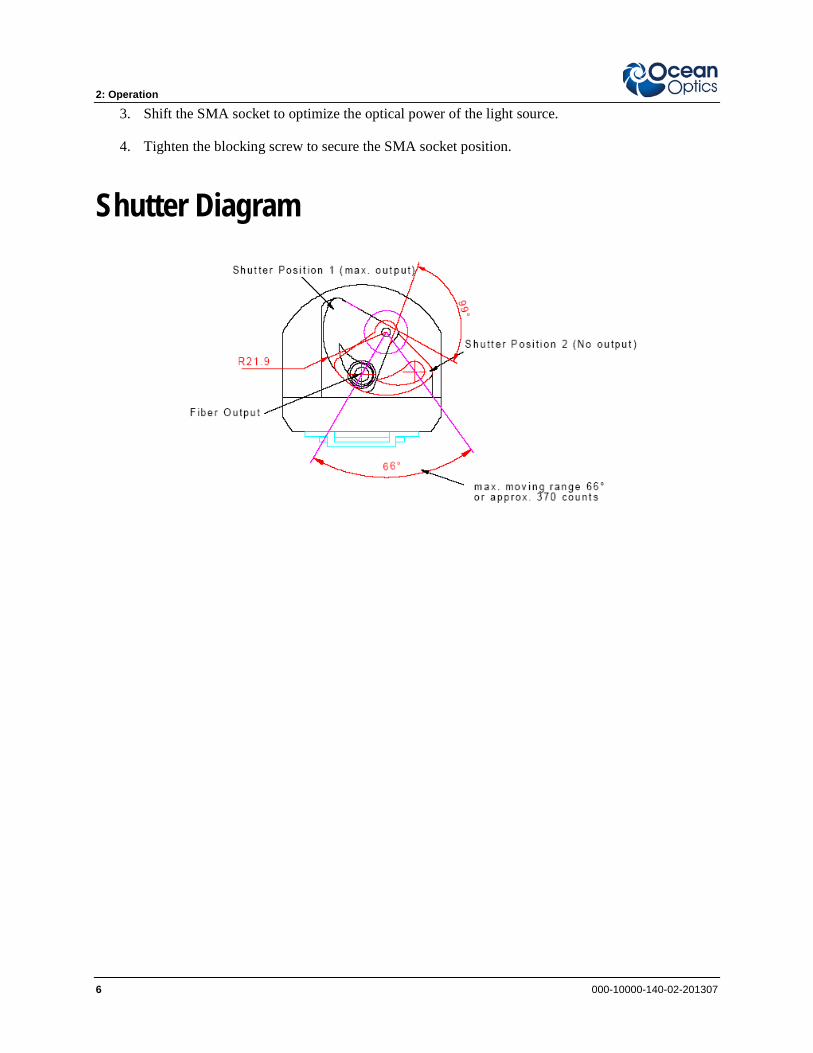
Shutter Diagram
000-10000-140-02-201307 7
Chapter 3
Bulb Replacement
Overview To order replacement bulbs for the HL-2000-HP-232, consult the Parts List.
WARNING
Before replacing the bulb in the light source, disconnect the lamp from your power source and allow the unit to cool for at least twenty minutes, if necessary.
Bulb Replacement Procedure ► Procedure
1. Remove the 19-inch cassette from the rack.
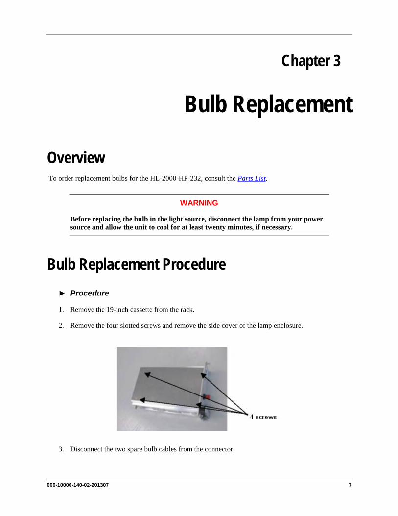
2. Remove the four slotted screws and remove the side cover of the lamp enclosure.
3. Disconnect the two spare bulb cables from the connector.
3: Bulb Replacement
8 000-10000-140-02-201307
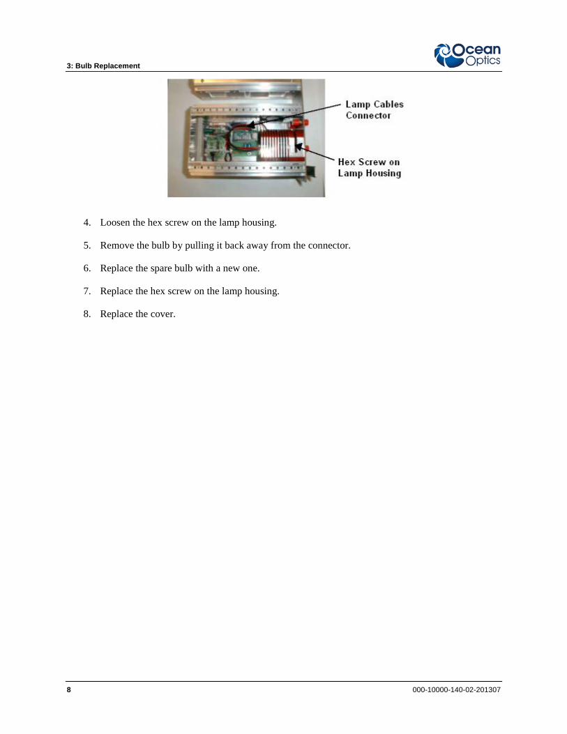
4. Loosen the hex screw on the lamp housing.
5. Remove the bulb by pulling it back away from the connector.
6. Replace the spare bulb with a new one.
7. Replace the hex screw on the lamp housing.
8. Replace the cover.
000-10000-140-02-201307 9
Appendix A
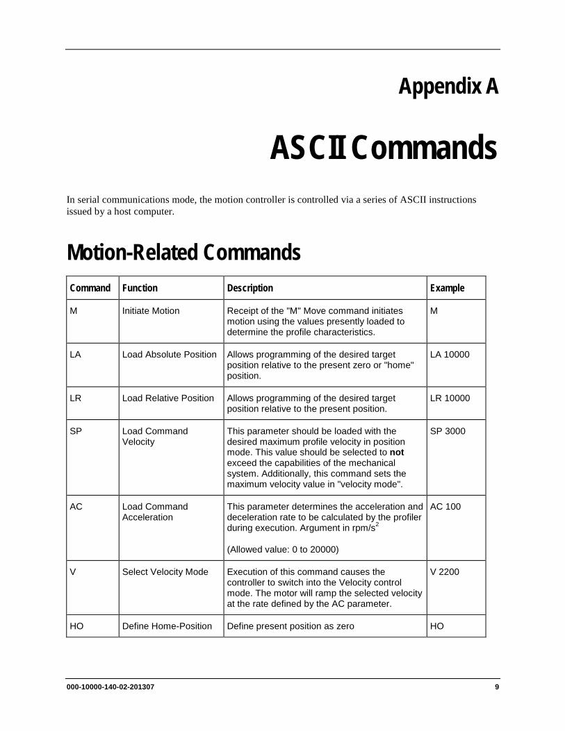
ASCII Commands In serial communications mode, the motion controller is controlled via a series of ASCII instructions issued by a host computer.
Motion-Related Commands Command Function Description Example
M Initiate Motion Receipt of the "M" Move command initiates motion using the values presently loaded to determine the profile characteristics.
M
LA Load Absolute Position Allows programming of the desired target position relative to the present zero or "home" position.
LA 10000
LR Load Relative Position Allows programming of the desired target position relative to the present position.
LR 10000
SP Load Command Velocity
This parameter should be loaded with the desired maximum profile velocity in position mode. This value should be selected to not exceed the capabilities of the mechanical system. Additionally, this command sets the maximum velocity value in "velocity mode".
SP 3000
AC Load Command Acceleration
This parameter determines the acceleration and deceleration rate to be calculated by the profiler during execution. Argument in rpm/s2
(Allowed value: 0 to 20000)
AC 100
V Select Velocity Mode Execution of this command causes the controller to switch into the Velocity control mode. The motor will ramp the selected velocity at the rate defined by the AC parameter.
V 2200
HO Define Home-Position Define present position as zero HO
A: ASCII Commands
10 000-10000-140-02-201307
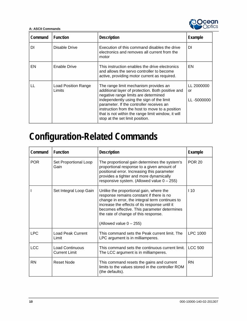
Command Function Description Example
DI Disable Drive Execution of this command disables the drive electronics and removes all current from the motor
DI
EN Enable Drive This instruction enables the drive electronics and allows the servo controller to become active, providing motor current as required.
EN
LL Load Position Range Limits
The range limit mechanism provides an additional layer of protection. Both positive and negative range limits are determined independently using the sign of the limit parameter. If the controller receives an instruction from the host to move to a position that is not within the range limit window, it will stop at the set limit position.
LL 2000000 or
LL -5000000
Configuration-Related Commands Command Function Description Example
POR Set Proportional Loop Gain
The proportional gain determines the system's proportional response to a given amount of positional error. Increasing this parameter provides a tighter and more dynamically responsive system. (Allowed value 0 – 255)
POR 20
I Set Integral Loop Gain Unlike the proportional gain, where the response remains constant if there is no change in error, the integral term continues to increase the effects of its response until it becomes effective. This parameter determines the rate of change of this response.
(Allowed value 0 – 255)
I 10
LPC Load Peak Current Limit
This command sets the Peak current limit. The LPC argument is in milliamperes.
LPC 1000
LCC Load Continuous Current Limit
This command sets the continuous current limit. The LCC argument is in milliamperes.
LCC 500
RN Reset Node This command resets the gains and current limits to the values stored in the controller ROM (the defaults).
RN
A: ASCII Commands
000-10000-140-02-201307 11
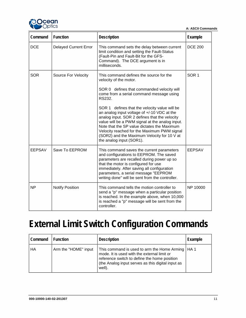
Command Function Description Example
DCE Delayed Current Error This command sets the delay between current limit condition and setting the Fault-Status (Fault-Pin and Fault-Bit for the GFS-Command). The DCE argument is in milliseconds.
DCE 200
SOR Source For Velocity This command defines the source for the velocity of the motor.
SOR 0 defines that commanded velocity will come from a serial command message using RS232.
SOR 1 defines that the velocity value will be an analog input voltage of +/-10 VDC at the analog input. SOR 2 defines that the velocity value will be a PWM signal at the analog input. Note that the SP value dictates the Maximum Velocity reached for the Maximum PWM signal (SOR2) and the Maximum Velocity for 10 V at the analog input (SOR1).
SOR 1
EEPSAV Save To EEPROM This command saves the current parameters and configurations to EEPROM. The saved parameters are recalled during power up so that the motor is configured for use immediately. After saving all configuration parameters, a serial message "EEPROM writing done" will be sent from the controller.
EEPSAV
NP Notify Position This command tells the motion controller to send a "p" message when a particular position is reached. In the example above, when 10,000 is reached a "p" message will be sent from the controller.
NP 10000
External Limit Switch Configuration Commands Command Function Description Example
HA Arm the "HOME" input This command is used to arm the Home Arming mode. It is used with the external limit or reference switch to define the home position (the Analog input serves as this digital input as well).
HA 1
A: ASCII Commands
12 000-10000-140-02-201307
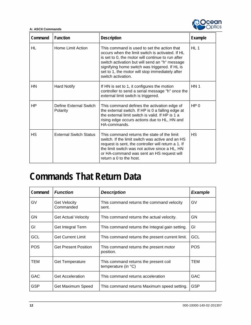
Command Function Description Example
HL Home Limit Action This command is used to set the action that occurs when the limit switch is activated. If HL is set to 0, the motor will continue to run after switch activation but will send an "h" message signifying home switch was triggered. If HL is set to 1, the motor will stop immediately after switch activation.
HL 1
HN Hard Notify If HN is set to 1, it configures the motion controller to send a serial message "h" once the external limit switch is triggered.
HN 1
HP Define External Switch Polarity
This command defines the activation edge of the external switch. If HP is 0 a falling edge at the external limit switch is valid. If HP is 1 a rising edge occurs actions due to HL, HN and HA-commands.
HP 0
HS External Switch Status This command returns the state of the limit switch. If the limit switch was active and an HS request is sent, the controller will return a 1. If the limit switch was not active since a HL, HN or HA-command was sent an HS request will return a 0 to the host.
HS
Commands That Return Data Command Function Description Example
GV Get Velocity Commanded
This command returns the command velocity sent.
GV
GN Get Actual Velocity This command returns the actual velocity. GN
GI Get Integral Term This command returns the Integral gain setting. GI
GCL Get Current Limit This command returns the present current limit. GCL
POS Get Present Position This command returns the present motor position.
POS
TEM Get Temperature This command returns the present coil temperature (in °C)
TEM
GAC Get Acceleration This command returns acceleration GAC
GSP Get Maximum Speed This command returns Maximum speed setting. GSP

A: ASCII Commands
000-10000-140-02-201307 13
Command Function Description Example
GRC Get Real Current This command returns the current being used in milliamperes
GRC
GST Get Status This command returns motion controller status.
Bit Description
Bit 0: 1... Position mode
0... Velocity mode
Bit 1: 1... Speed command is analog input
0... Speed command comes via RS232
Bit 2: 1... Speed command is PWM (SOR 2)
0... Speed command is analog voltage(SOR1)
Bit 3: 1... Amplifier Enabled
0... Amplifier Disabled
Bit 4: 1... In Position
0... Not in Position
Bit 5: 1... Rising edge on external switch is valid
0... Falling edge on external switch is valid
Bit 6: 1... External switch now high level
0... External switch now low level
GST
GFS Get Fault Status This command returns fault status.
Bit Description
(0 is normal, 1 is Fault present)
0 Over-temperature condition
1 Over-current condition
2 Under-voltage (< 15VDC)
3 Over-voltage (> 28VDC)
GFS
A: ASCII Commands
14 000-10000-140-02-201307
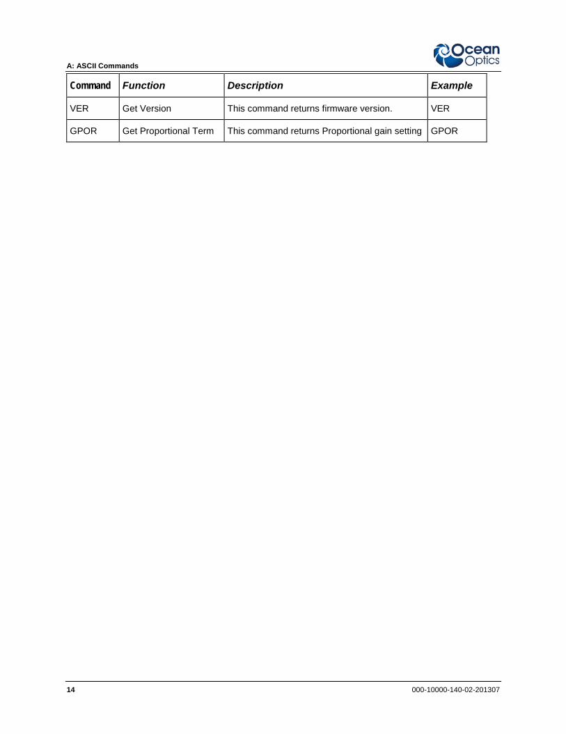
Command Function Description Example
VER Get Version This command returns firmware version. VER
GPOR Get Proportional Term This command returns Proportional gain setting GPOR

000-10000-140-02-201307 15
Appendix B
HL-2000-HP-232 Specifications
This section provides information on the operating environment, physical controls, and dimensions of the HL-2000-HP-232. It also provides a parts list.
Specifications Specification Criteria
Dimensions 60 mm x 130 mm x 190 mm
Weight 900 g
Pin description Pin 2: RX Pin 3: TX Pin 5: Ground
Output 20 watts
Output to bulb 1.6 A @ 24 VDC
Wavelength range 360–2400 nm
Spectral Range VIS - NIR
Stability 0.5%
Drift <0.3% per hour
Time to stabilize Approximately 5 minutes
Bulb lifetime 2,000 hours
Bulb color temperature 3,000 K
Temperature 5° C
Humidity 5–95% at 40° C
B: HL-2000-HP-232 Specifications
16 000-10000-140-02-201307
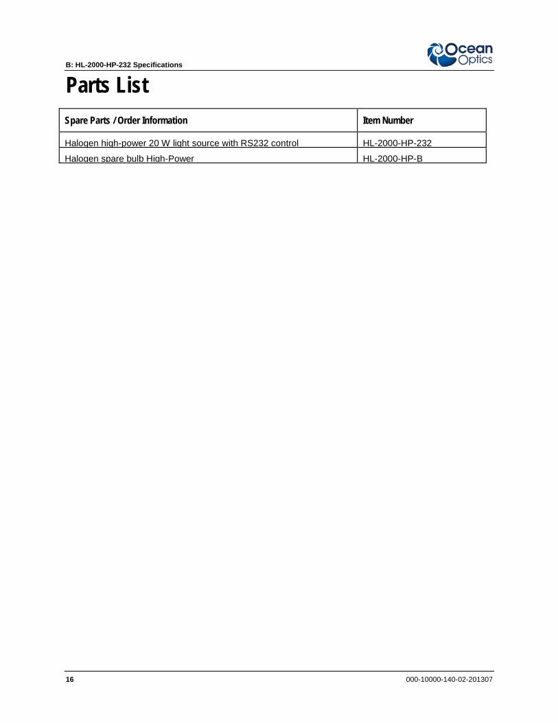
Parts List Spare Parts / Order Information Item Number
Halogen high-power 20 W light source with RS232 control
HL-2000-HP-232
Halogen spare bulb High-Power HL-2000-HP-B
000-10000-140-02-201307 17
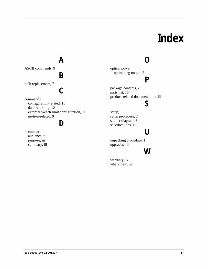
Index A
ASCII commands, 9
B bulb replacement, 7
C commands
configuration-related, 10 data-returning, 12 external switch limit configuration, 11 motion-related, 9
D document
audience, iii purpose, iii summary, iii
O optical power
optimizing output, 5
P package contents, 2 parts list, 16 product-related documentation, iii
S setup, 1 setup procedure, 2 shutter diagram, 6 specifications, 15
U unpacking procedure, 1 upgrades, iii
W warranty, A what's new, iii

Index
18 000-10000-140-02-201307