hambrew - world radio history
TRANSCRIPT

hambrew FOR AMATEUR RADIO DESIGNERS AID BUILDERS
KB8TPT's Benton Harbor Revisited
N7KSB: A Simple Multi-Band
Vertical
The hambrew Gallery
SPRING 1997 PERIODICALS POSTAGE PAID AT DENVER, COLORADO

• In Appreciation •
Larry Feick, NFOZ; Wes Farnsworth, KEONH (S.K.); Don McCoy, WAOHKC ; Jim Wiley, NOBLU ; Mike Liddy, KBOCZB; Bill Mason, NOKEP; Rob Kelly, NOSMR; Mike Manes, W5VSI; Will Sorensen, NORSD; Tom Crede, WB3JJK; Bruce Franklin, KG7CR; Edge of Space Sciences, Inc.; The NorthWest QRP Club; Fred Bonavita, W5QJM; Bruce O. Williams, WA6IVC; Mike Dinolfo, N4MWP ; Dave Clingerman, W6OAL; Bill Todd, N7MF B ; Roger Wendell,WBOJNR; ChuckAlbrecht, NOCKW; Don Zielinski, KOPVI; George Franklin, WOAV; Doug DeMaw, W1FB; Lew Smith, N7KSB; Roy Gregson, W6EMT; Wes Baden, K6EIL; Dick Pattinson, VE7GC; John Christopher, NG7D; John Pivnichny, N2DCH; Ernie Helton, W8MVN;Don Randall, WB5ROU ; Carl Merrill, N1QLC; James G. Lee, W6VAT; Bruce Muscolino, WA6TOY13; Dave Anthony, W5NOE; Roger Wagner, K6LMN; Steven O'Kelley, WA7SXB; Rev. George Dobbs, G3RJV; Jeffery C. Gibson, 9Y4AT; Dave Holesovsky, M PH; Kenneth Payton, KB5RQV; The Colorado QRP Club; Josh Logan, WX7K; Bill Shanney, KJ6GR; Dan Giles, VE7QM, Robert van der Zaal, PA3BHK;Bill Hickox, K5BDZ; Reg Tremblay, VE3GQD; Bob Seymour, WOLK; Bob Dennison, W2HBE; Wayne Burdick,
N6KR, Jorn Nielsen, SM5IFO; Cameron C.R. Bailey, KT3A; Don Callow, VK5AIL; Stan Cooper, K4DRD;Mike Branca, W3IRZ; Bill Kelsey, N8ET; Charles S. Fitch, W2IPI; Michael
Hopkins, AB5L;David Fifield, KB6ZBZ; John Woods, WB7EEL; Roy Parker, AA0B; Bob Shelton, N2EDF; Jeff Duntemann, KG7JF; Kent Ogletree, KD6NHP;Raymond Megirian, K4DHC; Marshall Emm, AAOXI;Igor A. Kenik, UA6OCC; George Rosenburg, KC6WDK; Bill Copeland, WB6RVE; ...And many others whom we cannot possibly list.

• Contents •
In Appreciation 2 The Hambrew Gallery: Projects from Past Issues 5 A Code Practice Transmitter: Lew Smith, N7KSB 25 ASimple Five Band Vertical: Lew Smith, N7KSB 27 Benton Harbor Revisited: Martin Cvitkovich, KB8TBT 32 A Dummy Load for Low Voltage DC Power Supplies: Nick Rankin, W4ZUS 36 Classified Ads 38
Photographic Credits:
Cover (top), pp. 32-35: Matthew Cvitkovich, KB8VVK; Cover (Bottom), pp. 25-29: Lew Smith, N7KSB
Hambrew Gallery Photo credits on each gallery page.
COPYRIGHT 1997, Smoking Pencil & Co. All Rights Reserved
FOR AMATEUR RADIO DESIGNERS AND BUILDERS SPRING, 1997 • VOL. 5, NO. 2
Publisher George De Grazio, WFOK
Writers, Editors and Contributors: Martin Cvitkovich, KB8TBT; Matthew Cvilkovkh, KB6VVK;Lew Smith, N7KSB;
Nick Rankin, W4ZUS; James G. Lee, W6VAT;
Editorial Office: (303) 989-5642 • [email protected]
Hambrew (ISSN 10773894) is published quarterly by Smoking Pencil & Co., Publishers, Offices at 13562 West Dakota Ave., Lakewood, Colorado 80228.
Periodicals Postage paid at Denver, Colorada POSTMASTER: Send address changes to Hambrew, P.O. Box 260083, Lakewood, CO 80226-0083.
Web page: http://www.qadas.corn/hambrew
Iiiiillem,„d1I11111111111111.11101111ql11111111111111Egm 111111111111111111 1111., 3
QRP KITS! NW8020
The user-acclaimed "HOT" Transceiver! Monobanders for 80, 40, 30, 20. 5 watts out, Real QSK, Superhet with Variable Bandwidth Crystal Ladder Filter, RIT, Loud Speaker Audio! + Lots of Fun! Easy test as you go instructions. Optional AF-1 Audio Filter for pulling in the weak ones. Specify the band, NWxx and/or optional AF-1 NVV's $75.00 + $5.00 S&H, AF-1
$20.00 (add $2.50 S&H if ordered separately)
EMTECH 3641A Preble St.
Bremerton, WA 98312 call 360-415-0804 or e-mail at
Use Ladder line? You need the "Ladder Grabber"!
Kits and DOS Software for Business and Ham Radio from Milestone Technologies. WB9KZY Island Keyer Kit $21.95
CODEMASTER Vrm Morse Training— 0-20WPM in 90 days guaranteed! En-dorsed for military Morse training.
$29.95.
M*LOG"" Logging Software, full featured, general purpose program with great
customizability. $39.95
S&H $5 per order, sales tax in CO only.
Marshall Emin, AAOXI Milestone Technologies
3140 S. Peoria St. Unit K-156 Aurora CO 80014-3155
(303) 752-3382 Credit card orders (Visa, MC, Amex,
Disc): 1-800-238-8205 [email protected]
www.mtechnologies.com/mthome
Hidden Antenna Covenant Restrictions / Apartments / Condos VHF, UHF, HF Amateur Radio Antenna Kit For Invisible and Portable/Mobile Applications
/ / / It's Paintable! X 0 Stick It On And
Color It Gone!
TapeTenna'
Kit Includes: 216' super conductive copper
tape, 50 page user manual and connectors.
HAMCO, Dept A
POB 25, Woodland Park, CO 80866
Check or M O for $54 ppd.
Write for Free Brochure!
4

The hambrew Gallery:
Projects from Past Issues
WOLK Tuner (photo: Bob Seymour, WOLK)
5

Top: The N2EDF 2-band tube transmitter (photo: Bob Shelton, N2EDF) Bottom: VE3GQD transceiver combo (photo: Reg Tremblay, VE3GQD)
6

Top: N7KSB Frequency Counter (photo: Lew Smith, N7KSB) Bottom: Hambrew's 15 Meter Receiver, based on a Neophyte "tunable IF"
and a crystal oscillator receive converter (photo: hambrew)
7

Top, Bottom: W5NOE Transmitter
(photo: Dave Anthony, W5NOE)
8

Top: W6EMT Z-Match (hambrew photo)
Bottom: Norcal Sierra Transceiver (photo: Stan Cooper, K4DRD)
9

Top: NWQRP's Xcvr designed by Roy Gregson, W6EMT, with digital frequency counter
added (hambrew photo)
Bottom: Roger Wagner, K6LMN 30 meter superhet receiver, bandspread added
(hambrew photo)
10

N7KSB Transmitter (photo: Lew Smith, N7KSB)
Jorn Nielsen 's shack with solar panel (photo: Jorn Nielsen, SM51F0)
11

Above: Tejas Kit's SWR Bridge, designed by Bill Hickox, K5BDZ
Left: Tejas dummy load (hambrew photos)
Left: Hambrew's Three Band Receiver Interior (6, 28, 50 MHz). (hambrew photo)
12

Mike Branca, W3IRZ designed a 9-Band antenna matching system for his loop antenna. This is the relay box and cable storage for
the device. (Photo: Mike Branca W3IRZ)
The Wilderness KC-1 Keyer and Frequency Counter was reviewed by Stan Cooper in the Autumn, '95 issue.
(Photo: Stan Cooper, K4DRD)
13

14

Opposite Page (top): Hambrew-built 30 Meter Ramsey transmitter kit with power meter added from used CB rig.
Opposite Page (bottom): Code practice oscillator and utility audio amp by Charles S. Fitch, W2IPI. (Photo: W2IPI)
This Page (top): 3-band receiver with two switchable receive converters. Receives
6m, 10m and the lower end of 40m. (hambrew photo) Bottom: Longwire Antenna tuner based on the W6EMT design.
(hambrew photo)
15

Above: The Elenco 6m/2m Receiver kit Below: WA6IVC's Emergenceiver (both photos: hambrew)
Opposite Page (top): The "Fireball" QRP trasmitter was reviewed by Roger Wendell,
WBOJNR (hambrew photo). Opposite Page (bottom): A very workable and useful antenna tuner designed and
built by legendary designer Roy Gregson, W6EMT (hambrew photo).
16

I8

Opposite Page (top): Another "L"-type antenna tuner (hambrew photo).
Opposite page (bottom):Wes Baden's great "Improved Neophyte Receiver" (photo: Wes Baden, K6EIL)
This page (top): Interior of the W6EMT antenna tuner seen on page 17, this issue.
19

Above: The MXM Transceiver, 20M version. Below: A workable "Noise Antenna", also known as a modified Jones Noise Cancelling
Circuit (hambrew photos) Opposite page (top): The famous NorCal 40 workhorse NorCal kit (photo: Stan Cooper,
K4DRD). Opposite Page (bottom): Interior of a T-type transmatch (hambrew photo).
20

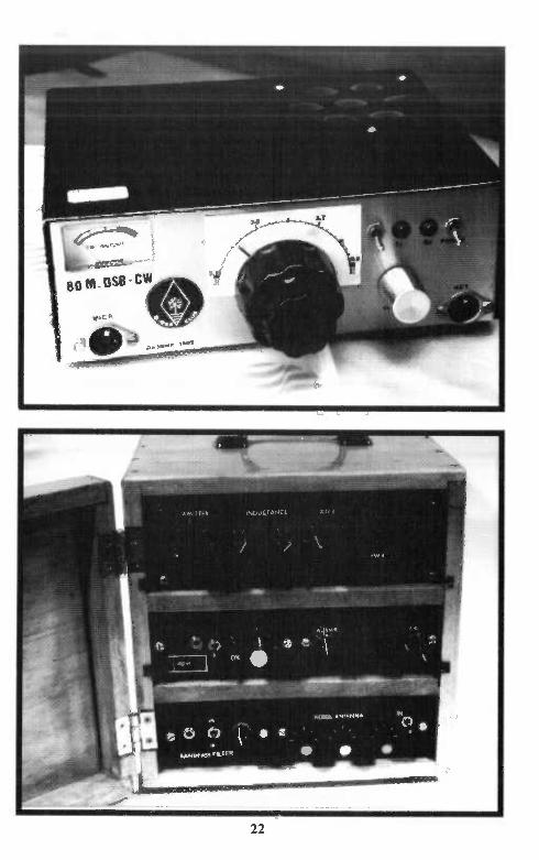

Opposite page (top) and this page: PA3BHK 's gorgeous Simple DSB & CW Transceiver for 80 Meters. A beautivul rig - well built!
(photos: Robert van der Zaal, PA3BHK)
Opposite page (bottom): hambrew's "Shack in a Box" featured the "Pixie" transceiver (250 Mw) and included an audio filter, antenna tuner in a drawer, and a noise antenna.
Perfect for portable QRP on 40m.
(hambrew photo)
23

Left: The N7KSB 2-meter hand held
transmitter - a real beaut! (photo: Lew Smith, N7KSB)
Below: Tejas kits produced a very compact two-stage audio filter
that worked very well to eliminate QRM. (hambrew photo)
24

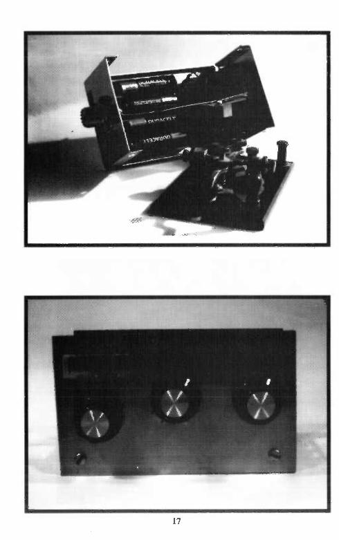
A Code Practice Transmitter Lew Smith, N7KSB
4176 N. Soldier Trail Tucson, AZ 85749
Mounted on a piece of wood by the author, this mighty mite slings CW up to a whopping 10 to 12 feet away! (photo by N7KSB)
Here is a project that could spark a youngster's interest in ham radio. The code practice transmitter is a
superregenerative oscillator that transmits a modulated RF signal on the AM broadcast hand.
Superregenerative action occurs when oscillator feedback is far in excess of that required for normal operation. This results in an oscillator that produces bursts of RF. The code practice transmitter sends 1 MHz RF bursts at an audio rate.
The code practice transmitter can be received on a nearby AM broadcast receiver. Maximum DX is 10 or 12 feet. The superregenerative action results in a signal that peaks in the middle of the AM broadcast band but is detectable all over the dial.
The circuit was built on a piece of 1" by 3" wood. Brass nails (3/4", #16 escutcheon pins) were used as solder terminals. Although the connections were soldered in this project, it is possible to avoid solder
25
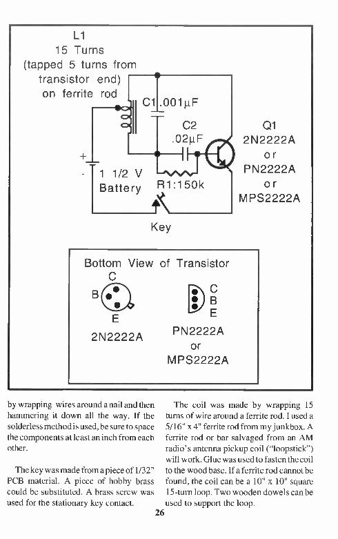
L1
15 Turns
(tapped 5 turns from
transistor end) on ferrite rod
1 1/2 V R Battery 1:150k
Key
Q1 2N2222A
or PN2222A
or M PS2222A
Bottom View
E
2N2222A
of Transistor
PN2222A or
MPS2222A
by wrapping wires around a nail and then hammering it down all the way. If the solderless method is used, be sure to space the components at least an inch from each other.
The key was made from a piece of 1/32" PCB material. A piece of hobby brass could be substituted. A brass screw was used for the stationary key contact.
The coil was made by wrapping 15 turns of wire around a ferrite rod. I used a 5/16" x 4" ferrite rod from my junkbox. A ferrite rod or bar salvaged from an AM radio's antenna pickup coil ("loopstick") will work. Glue was used to fasten the coil to the wood base. If a ferrite rod cannot be found, the coil can be a 10" x 10" square 15-turn loop. Two wooden dowels can be used to support the loop.
26

A Simple Five Band Vertical
Lew Smith, N7KSB 4176 N. Soldier Trail Tucson, AZ 85749
Here is a nice looking antenna that puts out a good signal on the
10, 12, 15, 17, and 20 meter DX bands. It is a simple, no trap, broadband design. Most of the materials can be purchased from local hardware stores.
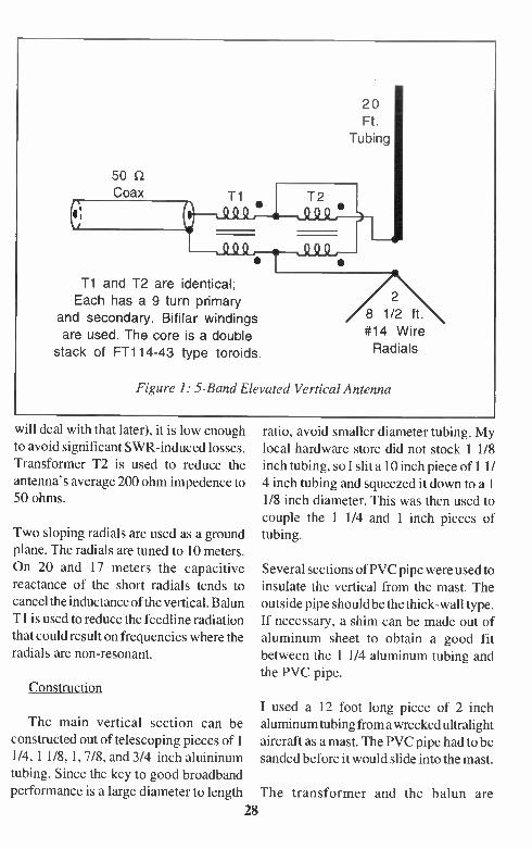
As shown in figure 1, the antenna consists of a 20 foot vertical section of aluminum tubing, two 8 1/2 foot wire radials, a 4:1 impedence ratio transformer, and a balun. Data from broadcast station towers' shows that a 1/2 wave end fed antenna with a large diameter to length
ratio will have an SWR of 3:1 or less
into 200 ohms over a 2:1 frequency range. Although a 3:1 SWR is still too high for most transmitters (I
27
20 Ft.
Tubing
50 S2 Coax Ti
Ti and T2 are identical; Each has a 9 turn primary
and secondary. Bifilar windings
are used. The core is a double stack of FT114-43 type toroids.
2 8 1/2 ft. #14 Wire Radials
Figure I: 5-Band Elevated Vertical Antenna
will deal with that later), it is low enough to avoid significant SWR-induced losses. Transformer T2 is used to reduce the
antenna's average 200 ohm impedence to 50 ohms.
Two sloping radials are used as a ground plane. The radials are tuned to 10 meters.
On 20 and 17 meters the capacitive reactance of the short radials tends to cancel the inductance of the vertical. Balun T 1 is used to reduce the feedline radiation that could result on frequencies where the radials are non-resonant.
Construction
The main vertical section can be constructed out of telescoping pieces of 1 1/4, 1 1/8, 1, 7/8, and 3/4 inch aluininum tubing. Since the key to good broadband performance is a large diameter to length
28
ratio, avoid smaller diameter tubing. My
local hardware store did not stock 1 1/8 inch tubing, so I slit a 10 inch piece of 1 1/ 4 inch tubing and squeezed it down to a 1 1/8 inch diameter. This was then used to couple the 1 1/4 and 1 inch pieces of tubing.
Several sections of PVC pipe were used to
insulate the vertical from the mast. The outside pipe should be the thick-wall type. If necessary, a shim can be made out of aluminum sheet to obtain a good fit between the 1 1/4 aluminum tubing and the PVC pipe.
I used a 12 foot long piece of 2 inch
aluminum tubing from a wrecked ultralight aircraft as a mast. The PVC pipe had to be
sanded before it would slide into the mast.
The transformer and the balun are

identical. They are hooked up differently to do their separate jobs. Both use a double stack of FT114-43 ferrite cores2. These cores
should handle 300 watts. FT240-43 cores should be used for higher power. Both T1 and T2 used a 9 turn bifilar winding. I used two lengths of 16 gauge hookup wire for each transformer.
A 2 inch PVC pipe
and a PVC end cap were used to house
Ti and T2. This housing was also
used to support the wire radials.
Adiustment
If possible, temporarily mount the antenna and check the SWR. The SWR can be tweaked to favor either 10 or 20 meters. Lengthening the vertical section by a foot decreases 20 meter SWR at the expense of the 10 meter SWR. Likewise, shortening the antenna favors the
—41 —) 50 12 Coax
To Antenna
Experimentally Determined Extra
Length of Coax
50 12 Coax
IC Figure 3: Stubless Tuner
)..) 50 S2 Coax (
To Transmitter
29

10 meter SWR at the expense of the 20 C 3183 ( 5-1 ) where C = capacitor meter SWR. value in pf
f = frequency in MHz S = SWR to be corrected A Stubless Tuner
Although a conventional antenna tuner could be used to match this antenna to a
transmitter, I prefer to use a "stubless" tuner. The stubless tuner is similar to a classical stub tuner3 except that the stub is replaced by a capacitor. As shown in figure 3, the stubless tuner consists of a mica capacitor and an experimentally
determined extra length of coax inserted between the capacitor and the antenna feedline. The coax can be coiled up and
fastened with plastic ties. One of these coax and capacitor networks is needed for each band.
A less than perfect, but still acceptable match is possible using the following capacitor values: 220 pf for 20 meters, 150 pf for 17 meters, and 120 pf for 15, 12, and 10 meters. Mica capacitors should handle up to 50 watts. Higher power will require transmitting capacitors capable of tolerating large RF currents. Alternately, the capacitor can be replaced by an open-ended coax stub3.
The extra length of coax will be between 0 and 11.5 feet on 10 meters and twice that on 20. Coax with foam insulation will be 20% longer. It helps if 1/2, 1., 2, 4, 8, and
A perfect match can be obtained by using 16 foot cables - with a male connector on the following formula: one end and a female connector on the
30

other end - are assembled and used in various combinations to determine the correct length for minimum SWR. Be aware that if feedline radiation is present, coiling the coax may change the required length somewhat.
Results
I have used various roof mounted ver-
sions of this antenna for 20 years. It is a very good DX antenna. The SWR on this version ranged from 2.0: 1 on 15 meters
to 2.8 : 1 on 20 meters. SWR at the transmitter after using the stubless tuner was less than 1.2: 1.
Notes
1 Chamberlain and Lodge, "The
Broadcast Antenna": Proceedings of the IRE vol 24, pp 11-35, Jan 1936 The data is also shown in figure 20.42, page 20.20 of the 1996 ARRL Handbook
2 Ferrite cores can be obtained from Amidon Associates, PO box 25867, Santa Ana, CA 92799
3 See discussion of "matching
stubs" in any edition of theARRL Antenna Handbook.. This antenna can be matched by replacing the capacitor with an open ended coax stub. Use a 6 foot stub on 20 meters, 4 feet on 17, and 3 feet on 15, 12, and 10 meters.
http://www..qadas.com/hambrew
IS THE PLACE TO go on the world wide web to
find availability of back issues
31
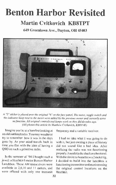
Benton Harbor Revisited Martin Cvitkovich KB8TPT 649 Greenlawn Ave., Dayton, OH 45403
A "2" sticker is placed over the original "6" on the face panel. The meter, toggle switch and the indicator lamp next to the meter were added by the previous owner and currently serve
no function. All original controls and lamps work as they did decades ago. (All photos this article by Matthew Cvitkovich, KB8VVK)
Imagine you're at a hamfest looking at an old outdated radio. You may wonder or try to remember how it was in the days
gone by. As your mind travels back in
time you flirt with the idea of having a QS0 on such a primitive radio.
In the summer of '94 I bought such a jewel: a Heathkit 6 meter Benton Harbor Lunchbox. These AM transceivers were
available in 2,6,10 and 11 meters, and
frequency and a variable receiver.
I had no idea what I was going to do with it, but just owning a piece of history did not sound like a bad idea. After
realizing the radio was not functioning properly, I used it in the shack as a bookend. With the desire to homebrew a 2 meter rig, I decided to build into the lunchbox a functioning transmitter and receiver using the original control locations on the
were offered with only one transmit Heathkit.
32

Rear view shows receive antenna, transmitter power terminals and coax for transmit antenna.
To simulate the original transmitting characteristics I chose a Ramsey FT 146. This kit offers 5 watts output with one crystal-controlled transmit frequency. For the receiver I chose a Ramsey FR 146. This receiver is capable of tuning the entire 2 meter band, so combined with the transmitter, this would simulate the Lunch-box of decades past.
Following the step by step instructions for assembling tbe transmitter and re-ceiver was fun and informative. After the transmitter and receiver boards were as-sembled, I mounted them on plywood. Here they were tested for proper opera-tion. The receiver worked flawlessly and required no antenna to receive the local
can receive simplex and repeaters from the surrounding counties. The transmitter
had an intermittent problem that I could not solve myself. The transmitter board was shipped to Ramsey for service and fine tuning. The lesson learned was to
solder all parts as close to the board as possible and clip the leads on the solder side of the board as close to the solder as
you can, using a file to smooth the lead to the solder.
Now that the boards were working properly it was time to wire them into the lunchbox. But first I had to remove the Heathkit chassis out of the box, leaving the speaker and indicator light sockets intact. I mounted a sheet of plexiglas on
repeater. With a little telescopic whip I the back of the speaker casing. The
33

The interior of the lunchbox. To the left are the Ramsey kit receive and transmit boards.
plexiglas is used to mount the transmitter and receiver boards.
A 10k pot with an on/off switch was mounted to the Heathkit face panel for on/
off-volume, and a 10k multi-turn pot was mounted to the panel for easy tuning. A
three rosition switch was mounted at the transmit/receive position on the face panel.
After de-soldering the volume and tune pots from the receiver board, a wire har-ness was improvised to connect the pots on the face panel to the receiver board. The on/off power switch is wired to sim-ply shift the power off from the 9volt battery hot wire. An LED to indicate
power-on was wired from the receiver board to the face panel indicator socket. The speaker wires were soldered to the original Heathkit speaker, and the squelch control left on the board set to OFFposition
to hear distant signals and to simulate the
noisy Heathkit regenerated receiver.
The transmitter board was much easier
to hook up, since nothing needed to be desoldered. The power wires were sent to
the back of the lunchbox to the power terminals. A foot of coax extrudes from the rear of the box for the transmit antenna.
Inside, the coax is plugged into the board using a standard jack. I wired an LED from the board to the power output
indicator on the Heathkit' s face panel, and plugged a microphone into the standard microhone jack. Also, I wired switching into the three position switch to simulate
old time keying. Recomended microphone innards were transplanted to an old Heathkit microphone case.
A telescopic whip was installed at the
rear of the box. Since the receiver runs off 34
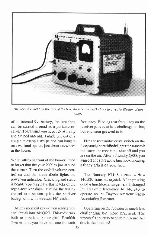
The license is held on the side of the box. An internal LED glows to give the illusion of hot tubes.
of an internal 9v. battery, the lunchbox can be carried around as a portable re-ceiver. To transmit you need 12v at 1 amp and a tuned antenna. I made one out of a
couple telescopic whips and can hang it on a wall and operate just about anywhere in the house.
While sitting in front of the two-er I tend
to forget that the year 2000 is just around the corner. Turn the on/off volume con-trol on and the green diode lights the power-on indicator. Crackling and static is heard. You may have flashbacks of the regen-receiver days. Turning the tuning control to a station quiets the receiver
background with pleasant FM audio.
After a moment or two you realize you can't break into this QS0. This radio was built to simulate the original Heathkit Two-er, and you have but one transmit
35
frecuency. Finding that frequency on the
receiver proves to be a challenge at first, but you soon get used to it.
Flip the transmit/receive switch on the face panel, the red diode lights the transmit
indicator, the receiver is shut off and you are on the air. After a friendly QSO, you
sign off and stare at the lunchbox,noticing a funny grin is on your face.
The Ramsey FT146 comes with a 146.520 transmit crystal. After proving out the lunchbox arrangement, I changed
the transmit frequency to 146.340 to operate on the Dayton Amateur Radio Association Repeater.
Operating on the repeater is much less challenging but more practical. The
repeater's courtesy beep reminds me that this is the nineties!

A Dummy Load for Low-
Voltage DC Power Supplies
Nick Rankin, W4ZUS 18 Jordan Dr., Pittsboro, NC 27312-8480
How many times have you needed to test a power supply under load? Here is a piece of test equipment that I have never seen in any catalog. You can adjust the current load from short to open, and anywhere in between.
I found some DC regulator boards that came out of old main frame computers. They can be found at electronic junkyards or some times at hamfests. The one I used had 6 power germanium transistors (marked Motorola 2471,8140,7439) mounted on a black, finned aluminum heat sink and strapped in parallel. Any similar type unit can be tried.
I cut one transistor out of the bank and connected it as a driver for the other parallel five. Then I used a 100 ohm ww power pot (rheostat) across the input to adjust the bias and conduction of the driver transistor which controls the bank of five connected across the input voltage as a variable, controllable load. Thus one can vary the load resistance and current
drawn by varying the bias on the driver transistor. The bank of load transistors will handle better than 50A for a few seconds.
See the schematic for details. I included a 0.01 ohm resistor in series with the load bank. Measuring the voltage drop across this resistor is a convenient way to measure large currents with a small VM (0.1 y = 10 a). I fused it for safety and included a switch to isolate the bank whenever necessary.
This unit lets me quickly test any low voltage (1 - 50v) power source for regulation or drop under load. Vary the load current and watch the input voltage vary. The less voltage change the better the regulation.
Another trick is to wire the adjust pot so you can either have the DC input volts across it or put a pair of jacks so you can put a signal generator output across the driver base and watch the dynamic regulation as the load follows the signal. This shows some odd results sometimes. My load tester worked throughout the
audio range acceptably, even though I could see distortion at higher frequencies
(depends on the response of the transistors).
Try this unusual piece of test equipment
36
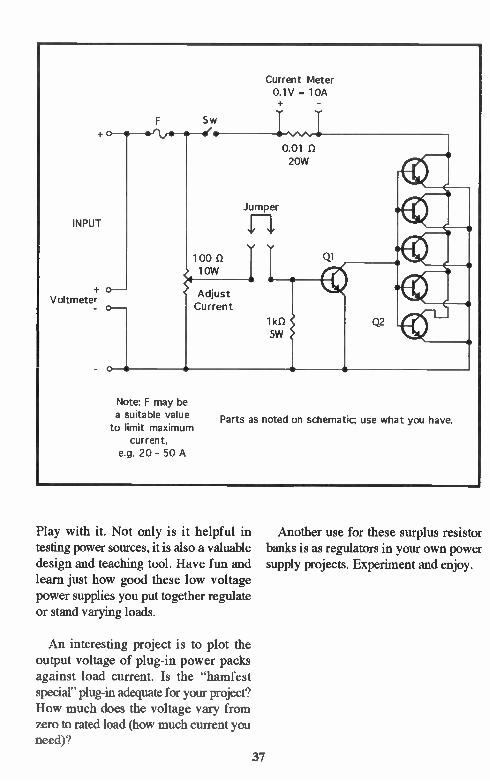
Current Meter 0.1V = 10A
INPUT
S w o--*--erb•-• —e•
0.01 20W
Jumper
loo low
Adjust Current
Note: F may be a suitable value to limit maximum
current, e.g. 20 - 50 A
Parts as noted on schematic; use what you have.
Play with it. Not only is it helpful in Another use for these surplus resistor testing power sources, it is also a valuable banks is as regulators in your own power design and teaching tool. Have fun and supply projects. Experiment and enjoy. learn just how good these low voltage power supplies you put together regulate or stand varying loads.
An interesting project is to plot the output voltage of plug-in power packs against load current. Is the "hamfest special" plug-in adequate for your project? How much does the voltage vary from zero to rated load (how much current you need)?
37

CLASSIFIED ADS A Reader Service of Hambrew - No charge to subscribers to place one ham-
related ad per issue, limit 15 words, 25 cents per word thereafter. Commercial or non-commercial subscribers, no minimum. All ads must be related to amateur radio. Hambrew does not vouch for nor guarantee the reliability nor legitimacy of any item or company
represented herein. Deadlines: Sept.1 (Autumn), Dec.1 (Winter), March 1 (Spring) June 1 (Summer). We reserve the right to deny publication of any ad. Copy To:
PO Box 260083, Lakewood, CO 80226-0083. Sorry, no phone orders on classified ads. Prepay only.
CHASSIS AND CABINET KITS: #10 SASE 5120-H HARMONY GROVE RD., DOVER, PA 17315. 717-292-4901 EVENINGS 2N4416A FETs for sale. Prime/JAN devices in ESD pack 10/$6.00 PPD to KC5RT, 701 Oakridge, Liberty, MO 64068
The History of QRP in the U.S. 1924-60 by Ade Weiss K8EFG/WORSP. 208 pages, 56 photos/16 illustrations-W1FB: "I recommend
this book for your Amateur Radio library, even if you never become a member of the fast-growing QRP fraternity..." WB8UUJ:"something to warm the cold winter nights with good memories.." $12/1st Class ($10 Sen. Cils.) AdeWeiss, 526 N. Dakota St, Vermillion, SD 57069 Builders! Hard-to-find ceramic rotary
switches. Ideal for bandswitching, antenna tuners, etc. Four wafers with single pole, five positions on each. Limited supply. $5 post-paid. Limit one per person. Unfilled orders returned. Fred Bonavita, W5QJM, Box 2764, San Antonio, TX 78299-2764
ELECTRONICS GRAB BAG! 500 PIECES OF NEW COMPONENTS: INDUCTORS,
CAPACITORS, DIODES, RESISTORS. $5 POSTPAID. ALLTRONICS, 2300 ZANKER RD., SAN JOSE, CA 95131 WANTED: SERVICE MANUAL/SCHE-
MATIC FOR JFD MODEL 7200 FIELD STRENGTH METER MARVIN MOSS, BOX 28601, ATLANTA, GA 30358 FOR SALE: TEN-TEC Argonaut II QRP XCVR, XLNT, $950/0B0. Call Bill, KJ6GR, (310) 542-9899
K6LMN Simple Superhet Monoband
Receivers: 80-10m. 6m converter. S.A. S.E. Roger Wagner, 2022 Thayer Ave., Los Angeles, CA 90025
Measure RF dBm Directly with dBm Meter. Complete kit, Unicorn Electronics, Valley Plaza Drive, Johnson City, NY 13790. (607) 798-0260. See Electronics Now, November, 1995, page 112.
1 Tube 80-40 breadboard transmitter kit.
Not a toy! Complete kit for both 80 and 40 meter amateur bands. To order send $39 to N2EDF, PO Box 185, Ogdensburg, NJ 07439. Or write for more information. WANTED: To borrow servicemanual/ schematics for Singer/Gertsch FM1OCS Station Monitor. Marvin Moss, Box 28601, Atlanta, GA 30358 Wanted: Cover for Precision 10-12 Tube
Tester. Schematic: 1924 Splitdorf model 500 Receiver. Wm. G. Mitch, 668 W. 725 So., Hebron, IN 46341 6 Meter Project Articles Wanted! Help us give 50 MHz a shot in the arm! Send to Hambrew- we're raising the fallen 6m banner! INVENTORY REDUCTION SALE- Prices slashed on kits and all parts. Bill Hickox, Tejas Kits, 9215 Rowan, Houston, TX 77036
WANTED: HAMBREW (WINTER, 1995) IN GOOD CONDITION. SASE for list of back issues of CQ, 73, Popular Electronics. All magazines in mint condition and in plastic covers. $1.00 each plus shipping. Bob Olson (WD4OHD), 6838 Hampton Wood Circle, Hixson, TN 37343
38

CLASSIFIED ADS QRP Kits Available: Kanga, Hands Elec-tronics, and KK7B designs $1 for catalog. Kanga US, Bill Kelsey, 3521 Spring Lake Dr.,Findlay, OH 45840 419-423-4604
NEW 1996-97 CATALOG AVAILABLE 2 Stamps to Dan's Small Parts and Kits, Box 3634, Missoula, MT 59806 Phone/FAX 1-.406-258-2782
DK3 SCREWDRIVER MOBILE AN-TENNA Parts Kit Available: Dave, KOIPH, 521 W. 33rd. St, Loveland, CO 80538, (970) 669-1674
Back Issues of Hambrew To Be Available TIlatil sold out or discon.tinued
we will contizaue to make _back issues of ha mbeew- available.
1\Te w Rates
_All back issues e6 ea _p_pa. in. "CIS 172terTiatiOriar e9 ea (C M funds) ppd.
Winter, Spring, Summer '95; Fall '96 are SOLD OUT
PO. Box 260083 Lakewood, CO 80226-0083
39

Tejas Kit FANTASTIC Winter SALE
Backpacker 11 Single Band QRP CW Transceiver Kit Reg. $159.95 Sale $129.95
Model TRFT 550 Specify band preference: 40,30, or 20 meters. (S&H $6.00 U.S.)
Deluxe flill electronic QSK CW transceiver kit. Highly sensitive receiver uses MiniCircuits double
balanced diode mixer. Unbelievable audio into your 8-32 obm phones or speaker. Front panel AF gain control also adjusts sidetone volume. Full RIT circuit with center detent control. Utilizes VFO/ HFO/ Mixer system. FREE built-in CW filter! All main operating controls on the front nanel. 200 kHz linear VFO tuning range with 6:1 vernier ball bearing drive for smooth positive main tuning. Stable as a rock! Output Power variable to 4 watts! Outstanding reviews in all Ham magazines. The Backpacker H is a complete kit, including a 45 page instruction manual and all parts, (we even include resin core solder!) • Power requirements: 11-14 Volts DC • Receive: Max 100 rit, 23 mA nominal • Transmit: 175 - 400 mA (4 watts out) • Weight: 23 oz • Size: 2 1/2" high x 7" wide x 6" deep.
Deluxe 8044ABM Mini-Keyer - WOW! Smallest keyer packed with features! PC board 1 7/8" X
2 1/8". PC board provisions to add other keyer "extras" designed into the 8044ABM chip, such as
weighted keying, speed indication meter, etc.! Requires 5 - 9 VDC. 92001A (CK) kit include-, 1" X 3 1/2"X 3" enclosure
92001 (EIK) (no enclosure) Reg. $39.95 (S&H $4.00 U.S.) SALE PRICE $29.95
92001 (CK) wIDeluxe enclosure Reg. $59.95 (S&H $4.00 U.S.) SALE PRICE $44.95 Variable Peaking Bandpass CW Filter Kit The "poor man's passband tuning" Just plug the Model 92150 CW filter into your receiver headphone jack, then plug your phones or speaker into filter, turn it on and tune. Minimum 8 ohm output (up to 32 ohms with some loss). Requires 9-12 volts DC. Only 1 1/4" X 4" X 3 1/4" Model 92150 (CK) Reg. $49.95 (S&H $4.00 U.S.) SALE PRICE $39.95 Mini Signal Strength Meter Just 1" X 3 1/2" X 3". 500 uA meter, sensitivity gain control and collapsible antenna. Great for fixed, portable, or mobile operation. (tested to over 450 MHz.)
Requires no power.
Model 92133 Assembled Reg. $29.95 (S&H $4.00 U.S.) SALE PRICE $19.95
Mini Meter Kit - Same attractive enclosure as above. Build your own test circuits such as low power dummy load / wattmeter / etc. to fit inside. Includes enclosure, 500 pA meter w / 0-10 scale, 10K pot, 2 US270 germanium diodes, two .1 pF Caps, and all mounting hardware. (S&H $4.00 U.S.) SALE PRICE $14.95
Remote In-line RF Sensor. Monitors antenna current on coax feed lines. Use osdlloscope, frequency counter, or meter circuit, to monitor your transmitted output signal. Negligible insertion loss. 1 MHz to 150 MHz (minimum). 1" X 3 1/2" X 3" aluminum case with two 50239 coax connectors and phono jack output connector.
Model 92111 Assembled Reg. $29.95 (S&H $4.00 U.S.) SALE PRICE $19.95 All Tejas Kits come complete, including all parts, an attractive clear anodized aluminum enclosure with tough epoxy silkscreened letters, hardware, and include a building instruction and operating manual.
All Items are Limited Quantities - subject to prior sale - no rain checks - all sales final!
Legal Size SASE to receive full Winter Sale flyer. All orders must include S&H. Refer to flyer order form for all S&H charges outside U.S. Prices and specifications subject to change without notice. We cannot accept credit cards, but we do accept
personal checks on U.S. Banks, bank checks, money orders, and postal orders. Please make all checks payable to Bill Hickox.
Bill Hickox, K5BDZ Tejas Kits • 9215 Rowan Lane
Houston, Texas 77036