hammond b-3 mk2 owner's manual - · pdf filethe hammond b-3 is the most popular organ...
TRANSCRIPT
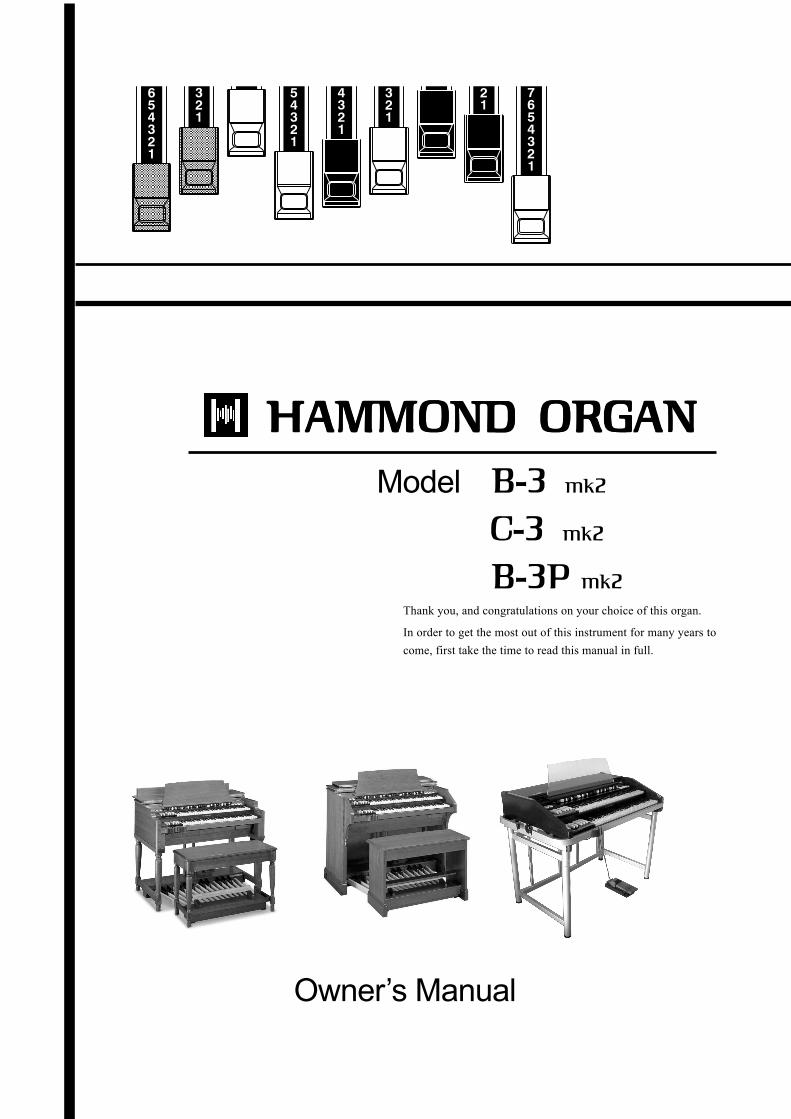
Model
Owner’s Manual
Thank you, and congratulations on your choice of this organ.
In order to get the most out of this instrument for many years to
come, first take the time to read this manual in full.

Owner’s Manual
IMPORTANT SAFETY INSTRUCTIONS
Read these instructions.
Keep these instructions.
Heed all warnings.
Follow all instructions.
Do not use this apparatus near water.
Clean only with dry cloth.
Do not block any ventilation openings.
Install in accordance with the manufacturer's instructions.
Do not install near any heat sources such as radiators, heatregisters, stoves or other apparatus (including amplifiers) thatproduce heat.
Do not defeat the safety purpose of the polarized or ground-ing-type plug. A polarized plug has two blades with one widerthan the other. A grounding type plug has two blades and athird grounding prong. The wider blade or third prong is pro-vided for your safety. If the provided plug does not fit into youroutlet, consult an electrician for replacement of the obsoleteoutlet.
Protect the power cord from being walked on or pinched, par-ticularly at plugs, convenience receptacles, and the point wherethey exit from the apparatus.
Only use attachments/accessories specified by the manufac-turer.
Use only with the cart, stand, tripod,bracket, or table specified by themanufacturer, or sold with the appa-ratus. When cart is used: use cautionwhen moving the cart/apparatus com-bination to avoid injury from tip-over.
Unplug this apparatus during lightning storms, or when unusedfor long periods of time.
Refer all servicing to qualified service personnel. Servicing isrequired when the apparatus has been damaged in any way,such as power-supply cord or plug is damaged, liquid has beenspilled or objects have fallen into the apparatus, the apparatushas been exposed to rain or moisture, does not operate nor-mally, or has been dropped.
Apparatus shall not be exposed to dripping or splashing andno objects filled with liquids, such as vases, shall be placed onthe apparatus.
WARNING: To reduce the risk of fire or electric shock, do notexpose this apparatus to rain or moisture.
The lightning flash with arrowhead symbol within an equi-
lateral triangle, indicates that dangerous voltage consti-
tuting a risk of electric shock is present within this unit.
The exclamation point within equilateral triangle, indicates
that there are important operating and maintenance in-
structions in the literature accompanying this unit.
In case in the future your instrument gets too old to play/use or mal-
functions beyond repair, please observe the instructions of this mark,
or, if any question, be sure to contact your dealer or your nearest
town or municipal office for its proper disposal.
Introduction
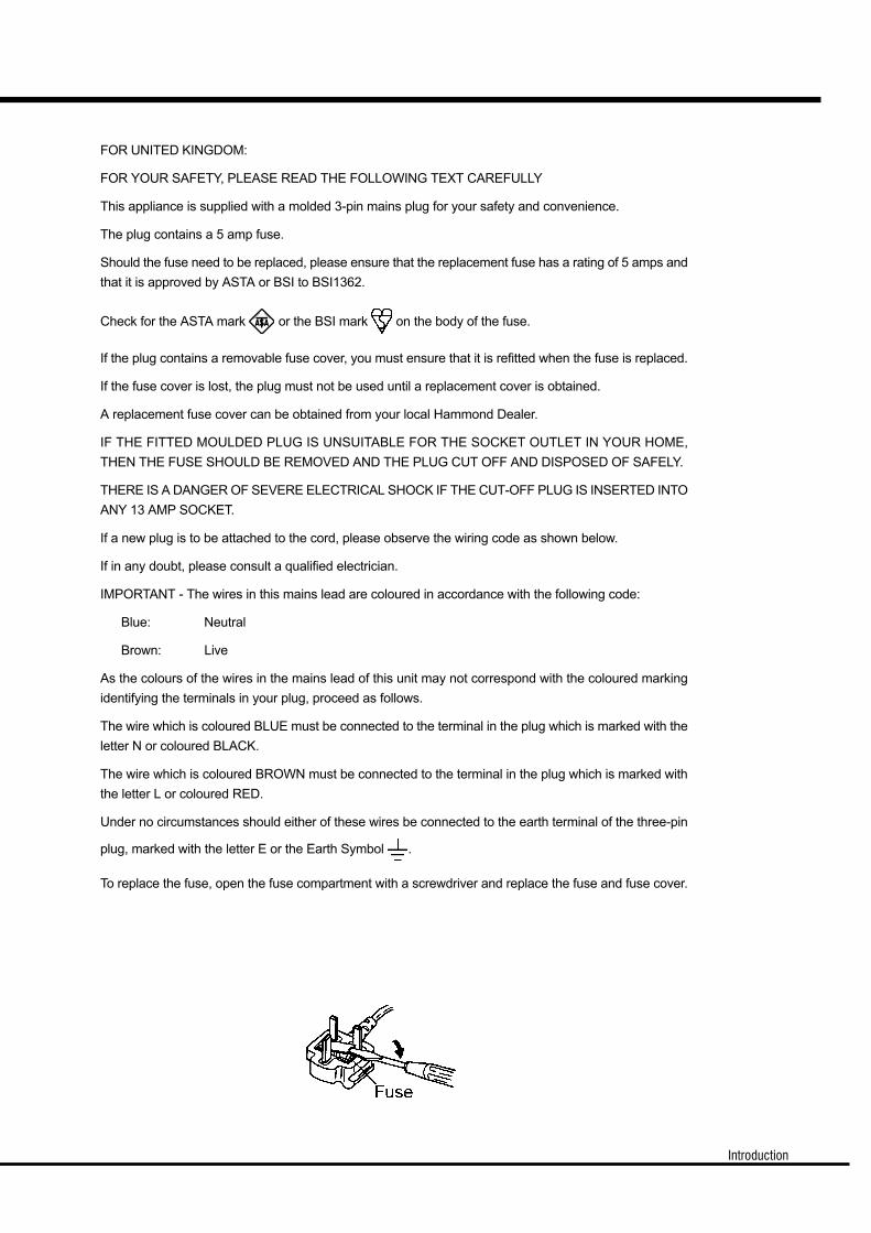
FOR UNITED KINGDOM:
FOR YOUR SAFETY, PLEASE READ THE FOLLOWING TEXT CAREFULLY
This appliance is supplied with a molded 3-pin mains plug for your safety and convenience.
The plug contains a 5 amp fuse.
Should the fuse need to be replaced, please ensure that the replacement fuse has a rating of 5 amps and
that it is approved by ASTA or BSI to BSI1362.
Check for the ASTA mark or the BSI mark on the body of the fuse.
If the plug contains a removable fuse cover, you must ensure that it is refitted when the fuse is replaced.
If the fuse cover is lost, the plug must not be used until a replacement cover is obtained.
A replacement fuse cover can be obtained from your local Hammond Dealer.
IF THE FITTED MOULDED PLUG IS UNSUITABLE FOR THE SOCKET OUTLET IN YOUR HOME,
THEN THE FUSE SHOULD BE REMOVED AND THE PLUG CUT OFF AND DISPOSED OF SAFELY.
THERE IS A DANGER OF SEVERE ELECTRICAL SHOCK IF THE CUT-OFF PLUG IS INSERTED INTO
ANY 13 AMP SOCKET.
If a new plug is to be attached to the cord, please observe the wiring code as shown below.
If in any doubt, please consult a qualified electrician.
IMPORTANT - The wires in this mains lead are coloured in accordance with the following code:
Blue: Neutral
Brown: Live
As the colours of the wires in the mains lead of this unit may not correspond with the coloured marking
identifying the terminals in your plug, proceed as follows.
The wire which is coloured BLUE must be connected to the terminal in the plug which is marked with the
letter N or coloured BLACK.
The wire which is coloured BROWN must be connected to the terminal in the plug which is marked with
the letter L or coloured RED.
Under no circumstances should either of these wires be connected to the earth terminal of the three-pin
plug, marked with the letter E or the Earth Symbol .
To replace the fuse, open the fuse compartment with a screwdriver and replace the fuse and fuse cover.
Owner’s Manual
IMPORTANT - PLEASE READ
The Hammond B-3 is the most popular organ evermade, and its sound is legendary. We have
designed this model to be true and authentic to the exact vintage detail, as well as providing a
large variety of modern features that allow greater flexibility no matter the musical style you wish
to play. This Owner’s Manual is designed to explain the operating features of this Hammond
organ as simply and graphically as possible.
Because we want to make this manual, as well as the keyboard itself, as easy to understand as
possible, the explanations in this manual are grouped by subject matter, and not in the order in
which they necessarily appear in the display (the screen in the left of the keyboard front panel).
For example, all functions pertaining to Drawbars are grouped together, all Percussion features
are treated as a group, and so on.
Also, each feature is treated as an explanation unto itself, and does not require you to already
have prior working knowledge of some other feature. The explanations are presented such that, if
you follow the steps, will be identical to that shown in the manual at that stage of the explanation.
Do not be daunted by the number of steps required to perform each operation. Each step is
simple. Simply bear these things in mind:
1. Read each step carefully.
2. Don’t skip any of the steps.
3. Don’t perform the steps out of sequence.
With these guidelines, you are well on your way to mastering all of the many sounds and features
of your Hammond organ.

Introduction
This organ uses a battery-backed RAM to remember your changes to the Parameters.
When the battery voltage becomes low, the Display will show:
BATTERY BACK UP
After the above message is displayed, this organ will re-initialize itself, and the factory default settings
will be restored (except Presets, Leslie Cabinets and Cutsom Tone-Wheels). It is a good idea to periodi-
cally save your data to CompactFlash card.
CAUTION: Batteries should only be changed by your dealer or a qualified techni-
cian.
If you see these messages, you should immediately back up your parameter changes, if you have made
any. If there is no battery installed in the unit, or if the battery is compeletely dead, the Display will show:
Owner’s Manual
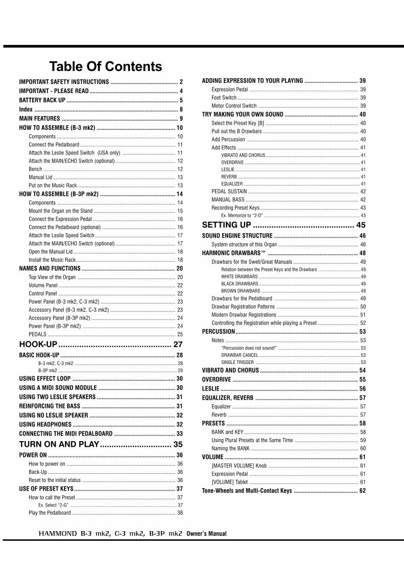
Table Of ContentsIMPORTANT SAFETY INSTRUCTIONS ............................................ 2IMPORTANT - PLEASE READ .......................................................... 4BATTERY BACK UP ......................................................................... 5Index .............................................................................................. 8MAIN FEATURES ............................................................................ 9HOW TO ASSEMBLE (B-3 mk2) ................................................... 10
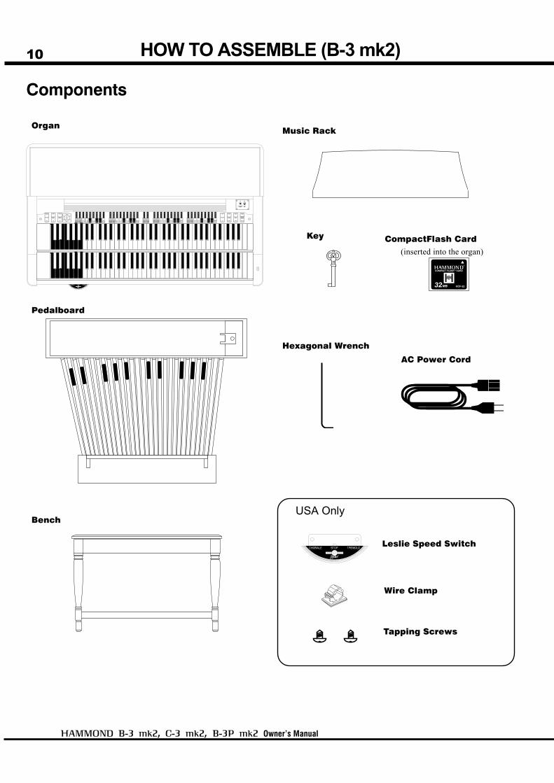
Components ....................................................................................... 10
Connect the Pedalboard ...................................................................... 11
Attach the Leslie Speed Switch (USA only) ....................................... 11
Attach the MAIN/ECHO Switch (optional) ............................................ 12
Bench ................................................................................................. 12
Manual Lid .......................................................................................... 13
Put on the Music Rack ........................................................................ 13
HOW TO ASSEMBLE (B-3P mk2) ................................................. 14Components ....................................................................................... 14
Mount the Organ on the Stand ............................................................ 15
Connect the Expression Pedal ............................................................. 16
Connect the Pedalboard (optional) ...................................................... 16
Attach the Leslie Speed Switch ........................................................... 17
Attach the MAIN/ECHO Switch (optional) ............................................ 17
Open the Manual Lid ........................................................................... 18
Install the Music Rack ......................................................................... 18
NAMES AND FUNCTIONS ............................................................. 20Top View of the Organ ........................................................................ 20
Volume Panel ...................................................................................... 22
Control Panel ...................................................................................... 22
Power Panel (B-3 mk2, C-3 mk2) ....................................................... 23
Accessory Panel (B-3 mk2, C-3 mk2) ................................................ 23
Accessory Panel (B-3P mk2) .............................................................. 24
Power Panel (B-3P mk2) .................................................................... 24
PEDALS .............................................................................................. 25
HOOK-UP................................................. 27BASIC HOOK-UP ........................................................................... 28
B-3 mk2, C-3 mk2 ...................................................................................... 28
B-3P mk2 .................................................................................................... 29
USING EFFECT LOOP ................................................................... 30USING A MIDI SOUND MODULE .................................................. 30USING TWO LESLIE SPEAKERS ................................................... 31REINFORCING THE BASS ............................................................. 31USING NO LESLIE SPEAKER ........................................................ 32USING HEADPHONES ................................................................... 32CONNECTING THE MIDI PEDALBOARD ........................................ 33
TURN ON AND PLAY............................... 35POWER ON ................................................................................... 36
How to power on ................................................................................ 36
Back-Up .............................................................................................. 36
Reset to the initial status ..................................................................... 36
USE OF PRESET KEYS .................................................................. 37How to call the Preset ......................................................................... 37
Ex. Select “2-G” .......................................................................................... 37
Play the Pedalboard ............................................................................ 38
ADDING EXPRESSION TO YOUR PLAYING ................................... 39Expression Pedal ................................................................................ 39
Foot Switch ......................................................................................... 39
Motor Control Switch .......................................................................... 39
TRY MAKING YOUR OWN SOUND ................................................ 40Select the Preset Key [B] .................................................................... 40
Pull out the B Drawbars ...................................................................... 40
Add Percussion .................................................................................. 40
Add Effects ......................................................................................... 41VIBRATO AND CHORUS ............................................................................... 41
OVERDRIVE ................................................................................................. 41
LESLIE ......................................................................................................... 41
REVERB ....................................................................................................... 41
EQUALIZER .................................................................................................. 41
PEDAL SUSTAIN ................................................................................. 42
MANUAL BASS ................................................................................... 42
Recording Preset Keys ........................................................................ 43Ex. Memorize to “2-D” ................................................................................. 43
SETTING UP ............................................ 45SOUND ENGINE STRUCTURE ....................................................... 46
System structure of this Organ ........................................................... 46
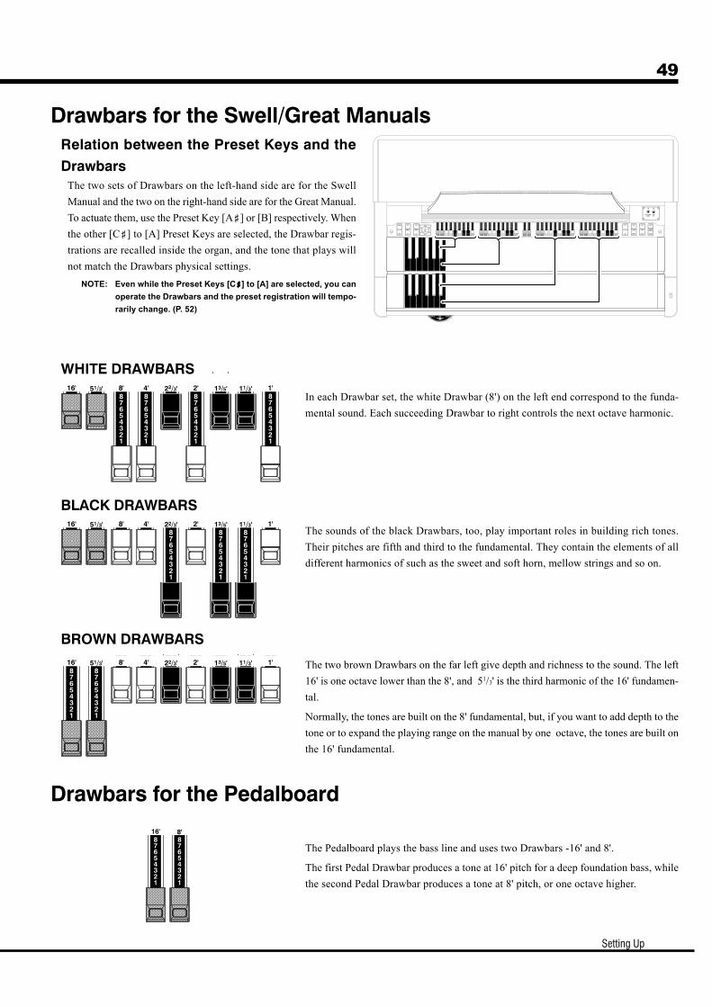
HARMONIC DRAWBARS™ ........................................................... 48Drawbars for the Swell/Great Manuals ................................................ 49
Relation between the Preset Keys and the Drawbars ................................... 49
WHITE DRAWBARS ..................................................................................... 49
BLACK DRAWBARS ..................................................................................... 49
BROWN DRAWBARS ................................................................................... 49
Drawbars for the Pedalboard .............................................................. 49
Drawbar Registration Patterns ............................................................ 50
Modern Drawbar Registrations ........................................................... 51
Controlling the Registration while playing a Preset .............................. 52
PERCUSSION ................................................................................ 53Notes .................................................................................................. 53
“Percussion does not sound!” ..................................................................... 53
DRAWBAR CANCEL ..................................................................................... 53
SINGLE TRIGGER ........................................................................................ 53
VIBRATO AND CHORUS ................................................................ 54OVERDRIVE .................................................................................. 55LESLIE .......................................................................................... 56EQUALIZER, REVERB ................................................................... 57
Equalizer ............................................................................................. 57
Reverb ................................................................................................ 57
PRESETS ...................................................................................... 58BANK and KEY .................................................................................... 58
Using Plural Presets at the Same Time ............................................... 59
Naming the BANK ............................................................................... 60
VOLUME ....................................................................................... 61[MASTER VOLUME] Knob .................................................................. 61
Expression Pedal ................................................................................ 61
[VOLUME] Tablet ................................................................................ 61
Tone-Wheels and Multi-Contact Keys .......................................... 62
Introduction
USING THE CONTROL PANEL ............... 63OPERATION CONTROL PANEL ...................................................... 64PLAY MODE .................................................................................. 65
How to read the Display ...................................................................... 65
Button operation in this mode ............................................................. 65
MENU MODE ................................................................................ 66How to read the Display ...................................................................... 66
Button operation in this mode ............................................................. 66
FUNCTION MODE ......................................................................... 67How to read the Display ...................................................................... 67
Button operation in this mode ............................................................. 67
Example: Increase the depth of Vibrato at [V-3]. ................................. 68
LOCK THE DISPLAY IN PLAY MODE ............................................. 70
SETTING THE PARAMETERS ................. 71DRAWBAR .................................................................................... 72
Setting the SWELL and GREAT Manual ........................................................ 72
Setting the PEDAL Part ................................................................................ 73
PERCUSS (PERCUSSion) ............................................................. 74TUNE ............................................................................................ 75PRESET ........................................................................................ 76
BANK NAME ................................................................................................ 76
PRESET LOAD ............................................................................................. 76
See the current value (Temporary Scope) ........................................... 78VIBRATO AND CHORUS ............................................................................... 78
PERCUSSION ............................................................................................... 79
LESLIE ......................................................................................................... 79
Other Knobs ................................................................................................. 79
TUBE AMP (TUBE pre-AMP) ........................................................ 80Bias voltage and Nonlinear Distor tion ................................................. 81
VIB&CHO (VIBrato and CHOrus) .................................................. 82Vibrato and Chorus of Hammond Organs ........................................... 83
LESLIE .......................................................................................... 84CABINET NUMBERS .................................................................................... 84
LESLIE PARAMETERS .................................................................................. 84
Record the Cabinets ........................................................................... 87
EQ/REV (EQualizer/REVerb) ......................................................... 88MANBS (MANual BaSs) ............................................................... 90CONTROL ..................................................................................... 91CUST. TW (CUSTom Tone-Wheels) ............................................... 92
Record the Custom Tone-Wheels ........................................................ 94
DEFAULT ....................................................................................... 95SYSTEM ....................................................................................... 96
MIDI ......................................................... 97ABOUT MIDI ................................................................................. 98
What is “MIDI”? .................................................................................. 98
MIDI terminals on this Organ .............................................................. 98
What the MIDI can do on your Organ .................................................. 98
MIDI STRUCTURE ....................................................................... 100CONTROLLING EXTERNAL MIDI EQUIPMENT ............................ 101EX. ZONE (EXternal ZONE) ......................................................... 102
SAVE THE SETUP ................................. 107SAVE YOUR SETUP .................................................................... 108
How to access the CF card slot ........................................................ 108
About the CF Card ............................................................................ 108CF CARD YOU CAN USE ............................................................................ 108
CF CARD SLOT .......................................................................................... 108
THE CARD CAPACITY AND CONTENT TO BE SAVED ................................. 108
INITIALIZE THE CF CARD ........................................................... 109SETUP PROCEDURES ................................................................. 110
How to read the Display .................................................................... 110
Save the SETUP ................................................................................ 110
Change the SETUP name .................................................................. 111
Loading the SETUP ........................................................................... 112
How to delete the SETUP .................................................................. 112
FREQUENTLY ASKED QUESTIONS ..... 113UTILIZING NEW FUNCTIONS & FEATURES ................................ 114TROUBLESHOOTING .................................................................. 115DAILY CARE AND MAINTENANCE ............................................... 116
APPENDIX ............................................. 117MIDI IMPLEMENTATION CHART ................................................. 118PARAMETERS ............................................................................. 119
Global Parameters ............................................................................ 119
Preset Parameters ............................................................................. 120Leslie Parameters ............................................................................. 122
System Parameters ........................................................................... 122
SPECIFICATIONS ........................................................................ 123FACTORY PRESETS .................................................................... 124SERVICE ..................................................................................... 127
IN THIS MANUAL:NOTE:s and appear frequently.
The NOTE: is a supplementary explanation.
The are explanations of terms and applications.

Owner’s Manual
Index
AAAAAAdjust Presets 40, 95, 108
BBBBBBank 37
Bend 39
CCCCCChorale 56
Combination Presets 58
CompactFlash 108
Custom Tone-Wheels 92
DDDDDDefault 95
Display Lock 70
Drawbars 40, 48, 72
EEEEEEcho 23, 24
Effect Loop 30
Equalizer 88, 57
Expression Pedal 39, 91
External Zones 100, 102
FFFFFFold-Back 72
Foot Switch 39, 91
Footage 48
Function Mode 67
GGGGGGreat Keyboard 21
IIIIIInitial Status 36
KKKKKKey Mode 73
LLLLLLeakage Noise 72
Leslie 41, 56, 84
MMMMMMain 23, 24
Manual Bass 42, 90
Master Tune 75
Menu Mode 66
MIDI 98
MIDI Pedalboard 33
Motor Control Switch 39, 91
OOOOOOverdrive 41, 55, 80
PPPPPPedal Sustain 42, 73
Pedalboard 25
Percussion 74, 40, 53, 74
Play Mode 65
Preset 76
Preset Key 40
RRRRRRegistration 40, 50, 52
Reverb 41, 57, 89
Rotary Channel 56
SSSSSSetup 110
Short Cut 79
Spring Reverb 91
Stationary Channel 56
Swell Keyboard 21
TTTTTTemporary Scope 78
Tone-Wheels 72
Transpose 75
Tremolo 56, 82
Tube Amp 55, 80
VVVVVVelocity 101, 104
Version 96
Vibrato 82
Vibrato and Chorus 41, 54
Volume 61
Introduction
9
MULTI-CONTACT MANUALSThe keyboards used in this organ have been totally redesigned and 100% faithfully replicates the “Direct Analog Keying
System” used on the original B-3.
TONE-WHEELS REBORN THROUGH DIGITAL TECHNOLOGYThe “Digital Tone-Wheel System” replicates the Tone-Wheel wave-forms created by the mechanical system of the
original B-3. The 96 wave-forms are always in oscillation just as in the original.
ALL CONTROLS EXACTLY AS ON THE ORIGINALAll the controls from the Panel Switches to the Preset Keys have been faithfully replicated. This organ can be played
with the same technique as the original B-3.
TUBE PRE-AMPLIFIERA pre-amp circuit using a 12AU7 tube is built in, and unique tube over-drive sounds are obtained. The bias-voltage-
adjustment function enables not only general clip distortion but also nonlinear distortion.
DIGITAL LESLIE/VIBRATOThe scanner vibrato and Leslie speaker are replicated via a DSP effects section. The Vibrato & Chorus effects are the
same as on the original B-3. The built-in Leslie gives the familiar Leslie sound when no actual Leslie speaker is available
or when practicing with headphones.
EQUALIZER AND TONE CONTROLA 3-band equalizer and tone-control are now built in. The equalizer can make fine or coarse tonal adjustments to the
bass, treble, and mid frequency ranges. The tone-control simulates the unique circuit built in on the vintage B-3 pre-amp
to obtain a gently-cut treble.
MIDI MASTER KEYBOARD3 external zones are available on each manual and pedalboard to enable this organ to be used as a master keyboard. A
MIDI pedalboard can also be used instead of the traditional pedalboard.
CompactFlash™ CARDYou can use a CompactFlash Card to save various Parameter files.
MAIN FEATURES
Owner’s Manual
10 HOW TO ASSEMBLE (B-3 mk2)
Components
USA Only
Organ
Pedalboard
Bench
Music Rack
Key CompactFlash Card(inserted into the organ)
Hexagonal Wrench
AC Power Cord
Leslie Speed Switch
Wire Clamp
Tapping Screws

Introduction
11
Connect the Pedalboard
1. Place the Pedalboard on the floor in front of the organ.
2. Take the Pedal Cable out of the organ and insert the plug
into the connector on the Pedalboard.
3. Hold the plug with the “Retention Hook” and lock it on
by turning the screw knob.
4. Slide and push in the Pedalboard beneath the organ until
it stops.
HA<
O>
HA<
O>
1. Locate a #2 Phillips Screw Driver.
2. Position the Leslie Speed Switch on the front left of the
Great Manual. The distance it from the left sideboard must
be 150 mm (6 in.) to allow for mounting the Main/Echo
Switch.
3. Attach the switch from the bottom with the tapping screws
supplied.
4. Insert the plug of the Leslie speed switch into the LESLIE
SWITCH Jack on the Volume Panel.
5. Affix the wire clamp on the bottom of the organ and affix
the cable.
Attach the Leslie Speed Switch
(USA only)
Owner’s Manual
12
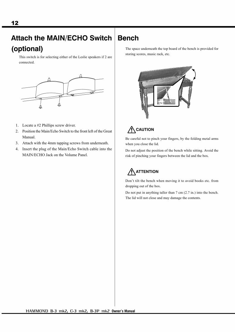
Attach the MAIN/ECHO Switch
(optional)This switch is for selecting either of the Leslie speakers if 2 are
connected.
1. Locate a #2 Phillips screw driver.
2. Position the Main/Echo Switch to the front left of the Great
Manual.
3. Attach with the 4mm tapping screws from underneath.
4. Insert the plug of the Main/Echo Switch cable into the
MAIN/ECHO Jack on the Volume Panel.
BenchThe space underneath the top board of the bench is provided for
storing scores, music rack, etc.
CAUTION
Be careful not to pinch your fingers, by the folding metal arms
when you close the lid.
Do not adjust the position of the bench while sitting. Avoid the
risk of pinching your fingers between the lid and the box.
ATTENTION
Don’t tilt the bench when moving it to avoid books etc. from
dropping out of the box.
Do not put in anything taller than 7 cm (2.7 in.) into the bench.
The lid will not close and may damage the contents.

Introduction
13
Manual Lid
1. When you open the lid, hold and lift the front gently with
both hands and fold it.
2. When you close the lid, hold the front of the folded lid
with both hands and put down gently to close.
ATTENTION
Be careful not to pinch your fingers when you open or close the
lid. If the player is a small child, be sure to help him/her to open
or close the lid.
Be sure to close and lock the lid before you move/carry the organ
and avoid any risk of injury.
Do not leave the score or music rack on the manual when you
close the lid.
Put on the Music RackInsert the Music Rack into the rail whenever necessary.
ATTENTION
Do not put excessive pressure on the music rack.
You can lock the key lid.
[B-3 mk2] The key hole is on the right side board.
[C-3 mk2] The key hole is on the front center.

Owner’s Manual
14 HOW TO ASSEMBLE (B-3P mk2)
Organ (closed view)
Expression Pedal
Music Rack (inside of the lid)
Hexagonal Wrench
AC Power Cord
Leslie Speed Switch, Spacer
Wire Clamp
Stand
Components
CompactFlash Card(inserted into the organ)
Introduction
15
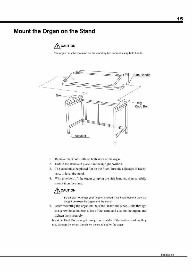
Mount the Organ on the Stand
CAUTION
The organ must be mounted on the stand by two persons using both hands.
1. Remove the Knob Bolts on both sides of the organ.
2. Unfold the stand and place it in the upright position.
3. The stand must be placed flat on the floor. Turn the adjusters, if neces-
sary, to level the stand.
4. With a helper, lift the organ gripping the side handles, then carefully
mount it on the stand.
CAUTION
Be careful not to get your fingers pinched! This could occur if they are
caught between the organ and the stand.
5. After mounting the organ on the stand, insert the Knob Bolts through
the screw holes on both sides of the stand and also on the organ, and
tighten them securely.
Insert the Knob Bolts straight through horizontally. If the knobs are askew, they
may damage the screw threads on the stand and/or the organ.

Owner’s Manual
16
Connect the Expression Pedal
Insert the plug the cable from the Expression Pedal to the
EXP.PEDAL connector on the power panel (on the bot-
tom of the organ), matching the direction, then tighten it
by turning the ring on it.
Connect the Pedalboard
(optional)
1. Insert the cable of the Pedalboard PK-25PR to the con-
nector of the Pedalboard and the PEDALBOARD con-
nector on the power panel (on the bottom of the organ),
matching the direction, and secure it by turning the ring
on the plug clockwise.
2. Insert the plug of the cable from the Expression Pedal to
the EXP.PEDAL connector on the power panel (on the
bottom of the organ), matching the direction, then fix it
by turning the ring on the plug clockwise.
Introduction
17
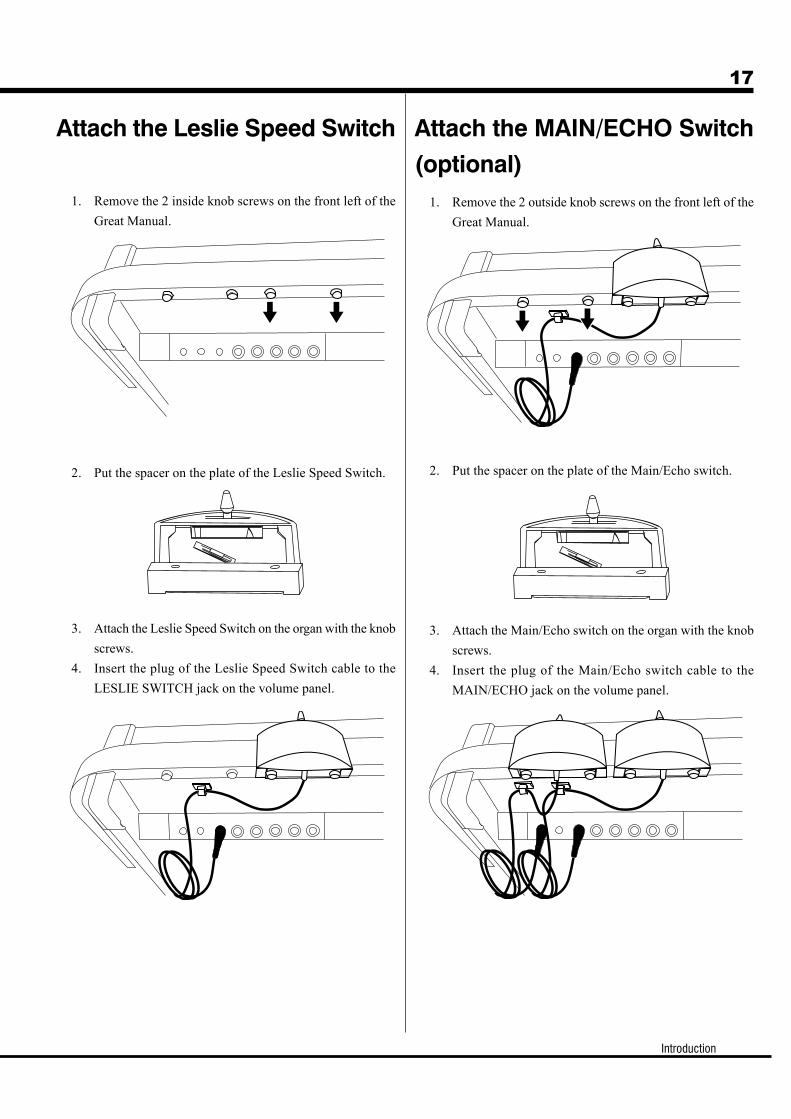
Attach the Leslie Speed Switch Attach the MAIN/ECHO Switch
(optional)1. Remove the 2 inside knob screws on the front left of the
Great Manual.
2. Put the spacer on the plate of the Leslie Speed Switch.
3. Attach the Leslie Speed Switch on the organ with the knob
screws.
4. Insert the plug of the Leslie Speed Switch cable to the
LESLIE SWITCH jack on the volume panel.
1. Remove the 2 outside knob screws on the front left of the
Great Manual.
2. Put the spacer on the plate of the Main/Echo switch.
3. Attach the Main/Echo switch on the organ with the knob
screws.
4. Insert the plug of the Main/Echo switch cable to the
MAIN/ECHO jack on the volume panel.
Owner’s Manual
18
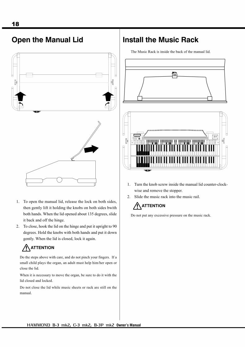
Open the Manual Lid
1. To open the manual lid, release the lock on both sides,
then gently lift it holding the knobs on both sides bwith
both hands. When the lid opened about 135 degrees, slide
it back and off the hinge.
2. To close, hook the lid on the hinge and put it upright to 90
degrees. Hold the knobs with both hands and put it down
gently. When the lid is closed, lock it again.
ATTENTION
Do the steps above with care, and do not pinch your fingers. If a
small child plays the organ, an adult must help him/her open or
close the lid.
When it is necessary to move the organ, be sure to do it with the
lid closed and locked.
Do not close the lid while music sheets or rack are still on the
manual.
Install the Music RackThe Music Rack is inside the back of the manual lid.
1. Turn the knob screw inside the manual lid counter-clock-
wise and remove the stopper.
2. Slide the music rack into the music rail.
ATTENTION
Do not put any excessive pressure on the music rack.

Introduction
19
Owner’s Manual
20
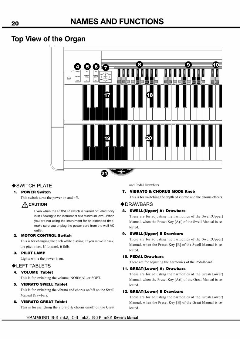
SWITCH PLATE1. POWER Switch
This switch turns the power on and off.
CAUTION
Even when the POWER switch is turned off, electricity
is still flowing to the instrument at a minimum level. When
you are not using the instrument for an extended time,
make sure you unplug the power cord from the wall AC
outlet.
2. MOTOR CONTROL SwitchThis is for changing the pitch while playing. If you move it back,
the pitch rises. If forward, it falls.
3. PILOT LAMPLights while the power is on.
LEFT TABLETS4. VOLUME Tablet
This is for switching the volume; NORMAL or SOFT.
5. VIBRATO SWELL TabletThis is for switching the vibrato and chorus on/off on the Swell
Manual Drawbars.
6. VIBRATO GREAT TabletThis is for switching the vibrato & chorus on/off on the Great
and Pedal Drawbars.
7. VIBRATO & CHORUS MODE KnobThis is for switching the depth of vibrato and the chorus effects.
DRAWBARS8. SWELL(Upper) A< Drawbars
These are for adjusting the harmonics of the Swell(Upper)
Manual, when the Preset Key [A<] of the Swell Manual is se-
lected.
9. SWELL(Upper) B DrawbarsThese are for adjusting the harmonics of the Swell(Upper)
Manual, when the Preset Key [B] of the Swell Manual is se-
lected.
10. PEDAL DrawbarsThese are for adjusting the harmonics of the Pedalboard.
11. GREAT(Lower) A< DrawbarsThese are for adjusting the harmonics of the Great(Lower)
Manual, when the Preset Key [A<] of the Great Manual is se-
lected.
12. GREAT(Lower) B DrawbarsThese are for adjusting the harmonics of the Great(Lower)
Manual, when the Preset Key [B] of the Great Manual is se-
lected.
NAMES AND FUNCTIONS
Top View of the Organ
4 5 6 109
17 18
19
21
20
7 8

Introduction
21
RIGHT TABLETS13. PERCUSSION Tablet
This is for switching the Percussion on/off.
14. PERCUSSION VOLUME TabletThis is for switching the volume of Percussion: NORMAL/SOFT.
15. PERCUSSION DECAY TabletThis is for switching the decay time of Percussion: FAST/SLOW.
16. PERCUSSION HARMONIC SELECTOR TabletThis is for switching the pitch of Percussion: THIRD harmonics
/ SECOND harmonics.
MANUALS17. SWELL(Upper) Preset Keys
These are for selecting the Presets of the Swell(Upper) Manual.
18. SWELL(Upper) ManualThis is a manual with 61 notes, multi-contacts (for Drawbars &
Percussion) with contacts (for MIDI OUT).
19. GREAT(Lower) Preset KeysThese are for selecting the Presets of the Great(Lower) Manual.
20. GREAT(Lower) ManualThis is a manual with 61 notes, multi-contacts (for Drawbars)
with contacts (for MIDI OUT).
LESLIE SWITCH21. LESLIE SPEED SWITCH
This is for switching the speed of the external Leslie speaker or
built-in Leslie effects.
13
2
11 15 161312 14
Owner’s Manual
22
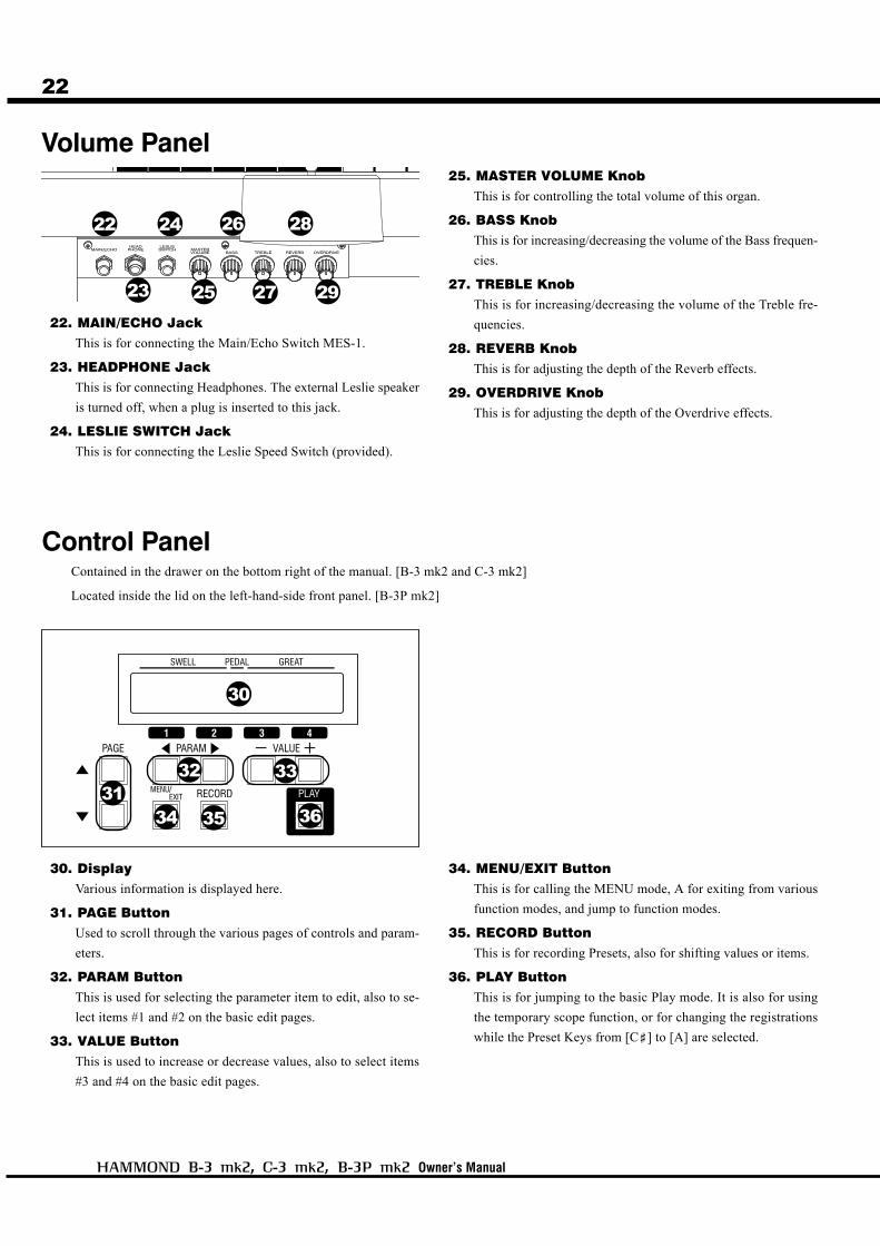
Volume Panel
Control PanelContained in the drawer on the bottom right of the manual. [B-3 mk2 and C-3 mk2]
Located inside the lid on the left-hand-side front panel. [B-3P mk2]
22. MAIN/ECHO JackThis is for connecting the Main/Echo Switch MES-1.
23. HEADPHONE JackThis is for connecting Headphones. The external Leslie speaker
is turned off, when a plug is inserted to this jack.
24. LESLIE SWITCH JackThis is for connecting the Leslie Speed Switch (provided).
25. MASTER VOLUME KnobThis is for controlling the total volume of this organ.
26. BASS KnobThis is for increasing/decreasing the volume of the Bass frequen-
cies.
27. TREBLE KnobThis is for increasing/decreasing the volume of the Treble fre-
quencies.
28. REVERB KnobThis is for adjusting the depth of the Reverb effects.
29. OVERDRIVE KnobThis is for adjusting the depth of the Overdrive effects.
30. DisplayVarious information is displayed here.
31. PAGE ButtonUsed to scroll through the various pages of controls and param-
eters.
32. PARAM ButtonThis is used for selecting the parameter item to edit, also to se-
lect items #1 and #2 on the basic edit pages.
33. VALUE ButtonThis is used to increase or decrease values, also to select items
#3 and #4 on the basic edit pages.
34. MENU/EXIT ButtonThis is for calling the MENU mode, A for exiting from various
function modes, and jump to function modes.
35. RECORD ButtonThis is for recording Presets, also for shifting values or items.
36. PLAY ButtonThis is for jumping to the basic Play mode. It is also for using
the temporary scope function, or for changing the registrations
while the Preset Keys from [C<] to [A] are selected.
22
23
24
33
34
32
29
31
28
27
26
25
35 36
30
Introduction
23
Accessory Panel (B-3 mk2, C-3 mk2)
SOUND INPUT TERMINAL37. LINE IN Jack
This is the terminal for connecting an external sound module or
a CD player. The signals input to this jack are output to the LINE
OUT jack, headphone jack, the stationary channel of each Leslie.
(Rating Input Level: 1.23V +4dBm, Input Impedance: 5kΩ)
SOUND OUTPUT TERMINAL38. LINE OUT Jack
The main output terminals, post internal effects (includes the
built-in Leslie effect).
Use both L and R, if the connected mixer or monitor speaker is
stereo, and use only L, if monaural.
When the Leslie speaker is connected, the built-in Leslie effect
appars on the L output only.
39. PEDAL OUT JackThis is an independent output terminal for the Pedal part.
EFFECT LOOP40. SEND Jack
This is a post-internal effects patch-out point.
If a plug is inserted to this jack, signals inside the organ are cut
off. (Rating Output Level: 1.23V +4dBm, Output Impedance:
600Ω)
41. RETURN JackThis is a post-internal effects patch-in point.
This jack is used also as the input terminal to the rotary channel
from an external sound source. (Rating Input Level: 1.23V
+4dBm, Input Impedance: 10kΩ)
MIDI TERMINAL42. MIDI OUT Jack
This is for sending playing information to external MIDI equip-
ment such as a Synthesizer or a Sound Module.
43. MIDI PEDAL IN JackThis is the input for a MIDI Pedalboard.
Power Panel (B-3 mk2, C-3 mk2)42. AC Inlet
Connects the A.C. Power Cable.
CAUTION
This organ shall be connected to a MAINS socket outlet with a protec-
tive earth (ground) connection.
LESLIE SOCKETS45. MAIN
Connect the first Leslie speaker here. If the Main/Echo switch (optional) is con-
nected to the MAIN/ECHO jack on the Volume Panel(#22), the sound is not
output unless you set the switch at the MAIN position.
46. ECHOConnect the second Leslie speaker to this. Sound is sent here, if you set the
optional Main/Echo switch to the echo position when the Main/Echo switch is
connected to this organ.
40 41
37 38
42 43
44 45 46
39
Owner’s Manual
24
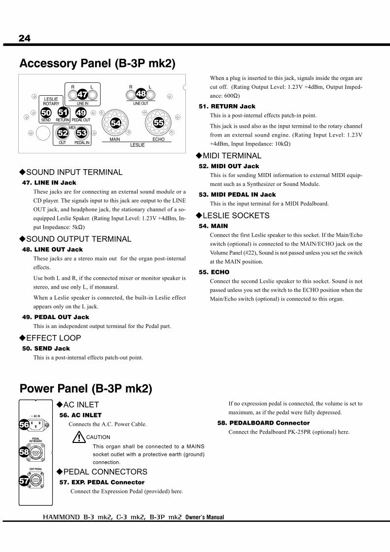
Accessory Panel (B-3P mk2)
SOUND INPUT TERMINAL47. LINE IN Jack
These jacks are for connecting an external sound module or a
CD player. The signals input to this jack are output to the LINE
OUT jack, and headphone jack, the stationary channel of a so-
equipped Leslie Spaker. (Rating Input Level: 1.23V +4dBm, In-
put Impedance: 5kΩ)
SOUND OUTPUT TERMINAL48. LINE OUT Jack
These jacks are a stereo main out for the organ post-internal
effects.
Use both L and R, if the connected mixer or monitor speaker is
stereo, and use only L, if monaural.
When a Leslie speaker is connected, the built-in Leslie effect
appears only on the L jack.
49. PEDAL OUT JackThis is an independent output terminal for the Pedal part.
EFFECT LOOP50. SEND Jack
This is a post-internal effects patch-out point.
When a plug is inserted to this jack, signals inside the organ are
cut off. (Rating Output Level: 1.23V +4dBm, Output Imped-
ance: 600Ω)
51. RETURN JackThis is a post-internal effects patch-in point.
This jack is used also as the input terminal to the rotary channel
from an external sound engine. (Rating Input Level: 1.23V
+4dBm, Input Impedance: 10kΩ)
MIDI TERMINAL52. MIDI OUT Jack
This is for sending MIDI information to external MIDI equip-
ment such as a Synthesizer or Sound Module.
53. MIDI PEDAL IN JackThis is the input terminal for a MIDI Pedalboard.
LESLIE SOCKETS54. MAIN
Connect the first Leslie speaker to this socket. If the Main/Echo
switch (optional) is connected to the MAIN/ECHO jack on the
Volume Panel (#22), Sound is not passed unless you set the switch
at the MAIN position.
55. ECHOConnect the second Leslie speaker to this socket. Sound is not
passed unless you set the switch to the ECHO position when the
Main/Echo switch (optional) is connected to this organ.
Power Panel (B-3P mk2)AC INLET
56. AC INLETConnects the A.C. Power Cable.
CAUTION
This organ shall be connected to a MAINS
socket outlet with a protective earth (ground)
connection.
PEDAL CONNECTORS57. EXP. PEDAL Connector
Connect the Expression Pedal (provided) here.
If no expression pedal is connected, the volume is set to
maximum, as if the pedal were fully depressed.
58. PEDALBOARD ConnectorConnect the Pedalboard PK-25PR (optional) here.
5354
51
5255
56
47 48
4950
58
57

Introduction
25
PEDALS59. EXPRESSION Pedal
This is for changing the total volume of the organ.
The Foot Switch is attached on the bottom left.
60. Pedalboard25 notes. Radial flat type, non-velocity keyboard.
61. Foot RestRest your feet when you are not playing the Pedalboard.
BBBBB-3 mk2-3 mk2-3 mk2-3 mk2-3 mk2
BBBBB-3P mk2-3P mk2-3P mk2-3P mk2-3P mk2
59
61
60
Owner’s Manual
26
27
Owner’s Manual
HOOK-UP

28
Owner’s Manual
See the figure below for connection.
This organ has no built-in speaker or amplifier. Before you con-
nect a Leslie Speaker to the organ, be sure to turn OFF the power
of the organ and the external equipment, if any is connected.
The Leslie Speaker is connected to the LESLIE/MAIN jack on
the organ using the exclusive 11-pin Leslie Cable attached to the
speaker or the LC-11-7M (optional).
Plug in the Leslie Cable to the jack, correctly matching the notches.
NOTE: Non-11-pin Leslie Speakers can also be connected to
the organ using a special adaptor kit. Ask your
Hammond Organ / Leslie dealer for details.
AC IN MAIN ECHOHOLES FOR CABLES (C-3 mk2)
Drilled holes are located on the side of the cabinet of the C-3 mk2
for your convenience.
B-3 mk2, C-3 mk2
BASIC HOOK-UP

Hook-Up
29
B-3P mk2
Fasten the cables using hook-and-loop fastners.
30
Owner’s Manual
USING EFFECT LOOP
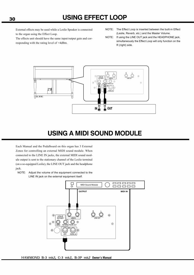
External effects may be used while a Leslie Speaker is connected
to the organ using the Effect Loop.
The effects unit should have the same input/output gain and cor-
responding with the rating level of +4dBm.
USING A MIDI SOUND MODULE
Each Manual and the Pedalboard on this organ has 3 External
Zones for controlling an external MIDI sound module. When
connected to the LINE IN jacks, the external MIDI sound mod-
ule output is sent to the stationary channel of the Leslie terminal
(on a so-equipped Leslie), the LINE OUT jack and the headphone
jack.
NOTE: Adjust the volume of the equipment connected to the
LINE IN jack on the external equipment itself.
NOTE: The Effect Loop is inserted between the built-in Effect
(Leslie, Reverb, etc.) and the Master Volume.
NOTE: If using the LINE OUT jack and the HEADPHONE jack,
simultaneously the Effect Loop will only function on the
R (right) side.
Hook-Up
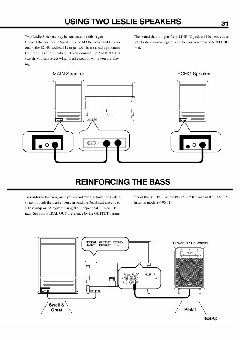
31USING TWO LESLIE SPEAKERS
Two Leslie Speakers may be connected to this organ.
Connect the first Leslie Speaker to the MAIN socket and the sec-
ond to the ECHO socket. The organ sounds are usually produced
from both Leslie Speakers. If you connect the MAIN/ECHO
switch, you can select which Leslie sounds while you are play-
ing.
The sound that is input from LINE IN jack will be sent out to
both Leslie speakers regardless of the position of the MAIN/ECHO
switch.
REINFORCING THE BASS
To reinforce the bass, or if you do not wish to have the Pedals
speak through the Leslie, you can send the Pedal part directly to
a bass amp or PA system using the independent PEDAL OUT
jack. Set your PEDAL OUT preference by the OUTPUT param-
eter of the OUTPUT on the PEDAL PART page in the SYSTEM
function mode. (P. 96 #1)

32
Owner’s Manual
USING NO LESLIE SPEAKER
If no Leslie Speaker is available, you can use the built-in Leslie
Effect by means of the LINE OUT jack.
If the Leslie Speaker and the LINE OUT jack are used together,
the built-in Leslie Effect is heard only on the L channel.
You may also use a traditional keyboard amp or PA system.
USING HEADPHONES
You can practice silently by connecting the stereo headphones to
the HEADPHONE jack of this organ.
When the plug is inserted to the HEADPHONE jack, the Leslie
Speaker is turned off, and the built-in digital Leslie Effect comes
online in the headphones.
ATTENTION
Hold the moulded part of the plug of the cord when you connect
or disconnect it to avoid the risk of breaking the cable.
Do not use excessive volume with headphones, due to risk hear-
ing damage.

Hook-Up
33CONNECTING THE MIDI PEDALBOARD
You may connect a MIDI Pedalboard, instead of the traditional
Pedalboard.
All the note information received at the MIDI PEDAL IN jack is
output as the Pedal Part, regardless of the MIDI channel.
The following MIDI pedalboards connectable to this organ are
also available from us as optional accessories:
XPK-100 (13 notes)
XPK-200 (20 notes)
NOTE: You can attach an expression pedal (provided with the
B-3P mk2) on the XPK-200.
NOTE: You can not use the functions of the XPK-100 such as
transpose, control, etc., if the XPK-100 is connected.

34
Owner’s Manual

35
Owner’s Manual
TURN ON AND PLAY

36
Owner’s Manual
How to power on
Back-Up
1. Set the [MASTER VOLUME] Knob at minimum.
2. Switch on the power of any external effects devices.
3. Turn on the [POWER] switch of the organ. The pilot lamp will light up and the PLAY
mode (fig.) is displayed, following the title. The Leslie Speaker is automatically turned on
simultaneously, if connected.
It takes a few seconds to reach play mode, because of the circuit-protection
devices.
The tubes require 10 to 20 seconds to warm up.
4. Turn on the power of the amplifier etc., if any connected to the LINE OUT.
5. Holding down a key, adjust the [MASTER VOLUME] by turning the Knob.
The Preset Key [B] does not produce sound when intially first turned on. Draw
the B Drawbars, or press either of the Preset Keys [C<] - [A] to start.
6. Adjust the volume of the amplifiers etc.
Reverse the above steps when you switch off the power. (Switch off the power
of the amplifiers etc. first.)
After connecting your organ to the power outlet, please follow this procedure before switching on
the power. To avoid possible damage to your speakers, please follow this procedure exactly.
Reset to the initial statusTo reset the organ to the initial default setting:
1. Switch off the power of the organ.
2. Holding the [RECORD] button, switch on the power.
3. Keep pressing the [RECORD] button until “Loading Default...” appears on the
display.
4. When the reset is complete, PLAY mode appears on the display. (Completed)
This organ memorizes the settings of the parameters immediately before it is switched off. The organ
will start with these settings when it is switched on again.
POWER ON

Turn On And Play
37USE OF PRESET KEYS
The registrations (settings) of the Drawbars and other pa-
rameters may be recorded to the Preset Keys on the left-
hand side of each manual.
There are 5 Banks with 11 Presets in each.
The 4 Banks are loaded with a default library of Presets
allowing you to play your organ immediately.
The chart on the left outlines the Bank/Preset structure.
The “Bank” is common for the entire organ, but the Preset Keys for the Swell and
Great are independent of each other and are selected separately.
Let’s call this in the example below.
NOTE: The Preset Key [C] produces no sound but releases the Preset Key
previously selected. It is called “cancel”.
How to call the PresetEx. Select “2-G”
1. Select the BANKSelect Bank 2 using [PARAM] Buttons in the PLAY mode.
2. Select the KEYPress the Preset Key [G].
The [G] key remains depressed and the contents of the Preset Key are called.
Try calling various Presets. See the Appendix “Factory Presets” (P. 124) at the
back of this manual for details of the contents of each Preset.
NOTE: Only the Drawbar registrations were able to be called on the origi-
nal B-3. The factory settings of this new organ are the same as the
factory settings of the original. You can change to call other pa-
rameters by the Preset Keys. See the “PRESET” section for de-
tails. (P. 76)
38
Owner’s Manual
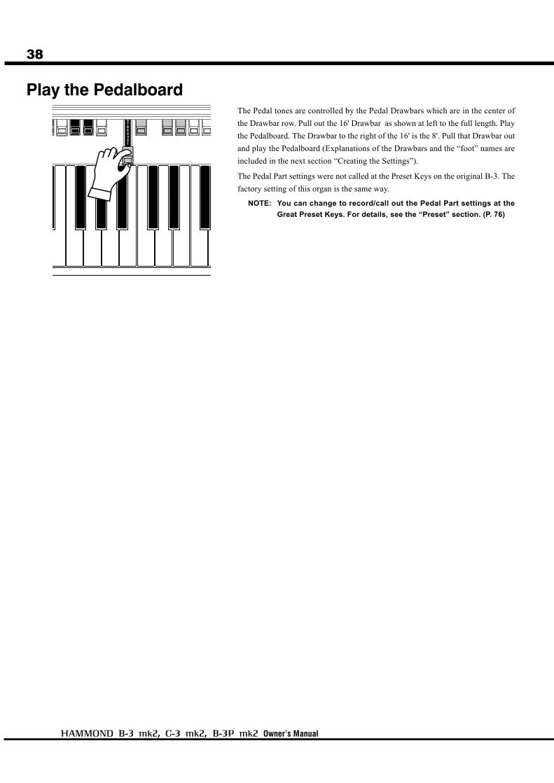
Play the PedalboardThe Pedal tones are controlled by the Pedal Drawbars which are in the center of
the Drawbar row. Pull out the 16' Drawbar as shown at left to the full length. Play
the Pedalboard. The Drawbar to the right of the 16' is the 8'. Pull that Drawbar out
and play the Pedalboard (Explanations of the Drawbars and the “foot” names are
included in the next section “Creating the Settings”).
The Pedal Part settings were not called at the Preset Keys on the original B-3. The
factory setting of this organ is the same way.
NOTE: You can change to record/call out the Pedal Part settings at the
Great Preset Keys. For details, see the “Preset” section. (P. 76)

Turn On And Play
39
Motor Control Switch
Expression Pedal
Foot Switch
ADDING EXPRESSION TO YOUR PLAYING
Unlike the piano, the organ does not get louder, the harder you play the keys. The
organ’s volume is controlled by using the expression pedal.
As you depress the pedal forward, the volume rises, and lowers when you return it.
NOTE: You can adjust the curve of the expression pedal. (P. 91)
The Foot Switch, on the left side of the Expression Pedal can be programmed for
various functions. “Leslie Chorale / Tremolo - Alternate” is the factory default.
Every time you depress the Foot Switch, the Leslie changes speed.
NOTE: You can change the Foot Switch assignment. (P. 91)
You can bend the pitch if you operate this switch while playing, same as the START
and RUN switches on the original B-3. While the toggle is at the UP position, the
pitch gradually goes up, and, while at the DOWN position, the pitch gradually
goes down to 2 octaves lower and also the volume gradually gets smaller.
NOTE: You can change the time of the pitch bend. (P. 91)
START AND RUN
The original B-3 required a two-step procedure to power up. You would first “start”
the motors by holding the spring-loaded left switch, and after a few seconds, you
would release the “start” switch and turn on the “run” switch. Organists discoverd
that if you engaged the start switch while the organ was running, it would give a
distinctive “pitch bend” to the organ tone. This organ, being totally digital only
needs the power switch, but to remain authentic, the motor control switch is in-
cluded, and the “pitch bend” effect is duplicated.
40
Owner’s Manual
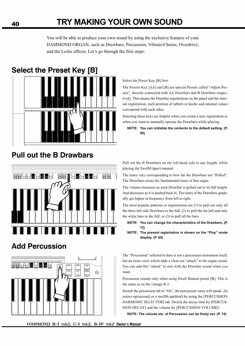
TRY MAKING YOUR OWN SOUND
You will be able to produce your own sound by using the exclusive features of your
HAMMOND ORGAN, such as Drawbars, Percussion, Vibrato/Chorus, Overdrive,
and the Leslie effects. Let’s go through the first steps:
Select the Preset Key [B]
Pull out the B Drawbars
Add Percussion
Select the Preset Key [B] first.
The Presets Key [A<] and [B] are special Presets called “Adjust Pre-
sets”, directly connected with A< Drawbars and B Drawbars respec-
tively. That means the Drawbar registrations on the panel and the inter-
nal registration, each position of tablets or knobs and internal values
correspond with each other.
Selecting these keys are helpful when you create a new registration or
when you want to manually operate the Drawbars while playing.
NOTE: You can initialize the contents to the default setting. (P.
95)
Pull out the B Drawbars on the left-hand side to any length, while
playing the Swell(Upper) manual.
The tones vary corresponding to how far the Drawbars are “Pulled”.
The Drawbars create the fundamental tones of this organ.
The volume increases as each Drawbar is pulled out to its full length.
And decreases as it is pushed back in. The tones of the Drawbars gradu-
ally get higher in frequency from left to right.
The most popular patterns or registrations are (1) to pull out only all
the three left side Drawbars to the full, (2) to pull the far-left and only
the white bars to the full, or (3) to pull all the bars.
NOTE: You can change the characteristics of the Drawbars. (P.
72)
NOTE: The present registration is shown on the “Play” mode
display. (P. 65)
The “Percussion” referred to here is not a percussion instrument itself,
but an extra voice which adds a clear-cut “attack” to the organ sound.
You can add this “attack” to mix with the Drawbar sound when you
want.
Percussion sounds only when using Swell Manual preset [B]. This is
the same as on the vintage B-3.
Switch the percussion tab to “On”, the percussion voice will speak. An
octave up(second) or a twelfth up(third) by using the [PERCUSSION
HARMONIC SELECTOR] tab. Switch the decay time by [PERCUS-
SION DECAY] and the volume by [PERCUSSION VOLUME].
NOTE: The volume etc. of Percussion can be finely set. (P. 74)

Turn On And Play
41
Add Effects
LESLIE
VIBRATO AND CHORUS
OVERDRIVE
REVERB
“Vibrato and Chorus” slightly changes the Drawbar pitch and adds warmth to the sound.
[SWELL] Tablet, [GREAT] TabletSwitches the Vibrato/Chorus on and off for each manual.
[VIBRATO AND CHORUS MODE] KnobControls the Vibrato and Chorus Depth.
The degree of depth corresponds with the number. “V” adds Vibrato sound by changing the pitch,
“C” adds the original shimmering Hammond chorus.
NOTE: You can fine-adjust the speed etc. of the Vibrato&Chorus. (P. 82)
Adds tube-based distortion to the sound.
[OVERDRIVE] KnobControls the distortion amount. Full left is “clean”. The distortion effect increase as you rotate the
knob clockwise.
NOTE: Overdrive distortion can be fine-set. (P. 80)
The Leslie speaker uses a rotating treble horn and a woofer firing into a rotating drum to give the
organ a “3-D” sound, with motion and lively dynamics. It is the traditional partner of the Hammond
Organ.
LESLIE SPEED SwitchThis is for switching the mode of the Leslie Speaker or the built-in Leslie Effect.
At CHORALE the rotor turns slowly, at TREMOLO fast. It stops at STOP.
NOTE: You can fine-adjust the rotation speed etc. of the internal LESLIE Effect. (P. 84)
The reverb effect simulates performing in a concert-hall.
[REVERB] KnobControls the depth of the Reverb Effect. At full left the Reverb Effect is off. The effect deepens as
you rotate the knob.
NOTE: You can fine-control time etc. of Reverb. (P. 88)
EQUALIZER
Controls the overall tone of the organ.
[BASS] KnobIncreases or decreases the emphasis of the Bass range of sound.
[TREBLE] KnobIncreases or decreases the emphasis of the Treble range of sound.
NOTE: Each BASS, TREBLE knob can be assigned to a different band respectively. (P. 88
#6, 7)
42
Owner’s Manual
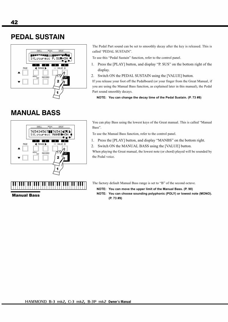
MANUAL BASSYou can play Bass using the lowest keys of the Great manual. This is called “Manual
Bass”.
To use the Manual Bass function, refer to the control panel.
1. Press the [PLAY] button, and display “MANBS” on the bottom right.
2. Switch ON the MANUAL BASS using the [VALUE] button.
When playing the Great manual, the lowest note (or chord) played will be sounded by
the Pedal voice.
The factory default Manual Bass range is set to “B” of the second octave.
NOTE: You can move the upper limit of the Manual Bass. (P. 90)
NOTE: You can choose sounding polyphonic (POLY) or lowest note (MONO).
(P. 73 #9)
PEDAL SUSTAINThe Pedal Part sound can be set to smoothly decay after the key is released. This is
called “PEDAL SUSTAIN”.
To use this “Pedal Sustain” function, refer to the control panel.
1. Press the [PLAY] button, and display “P. SUS” on the bottom right of the
display.
2. Switch ON the PEDAL SUSTAIN using the [VALUE] button.
If you release your foot off the Pedalboard (or your finger from the Great Manual, if
you are using the Manual Bass function, as explained later in this manual), the Pedal
Part sound smoothly decays.
NOTE: You can change the decay time of the Pedal Sustain. (P. 73 #8)
1
2
1
2
Turn On And Play
43
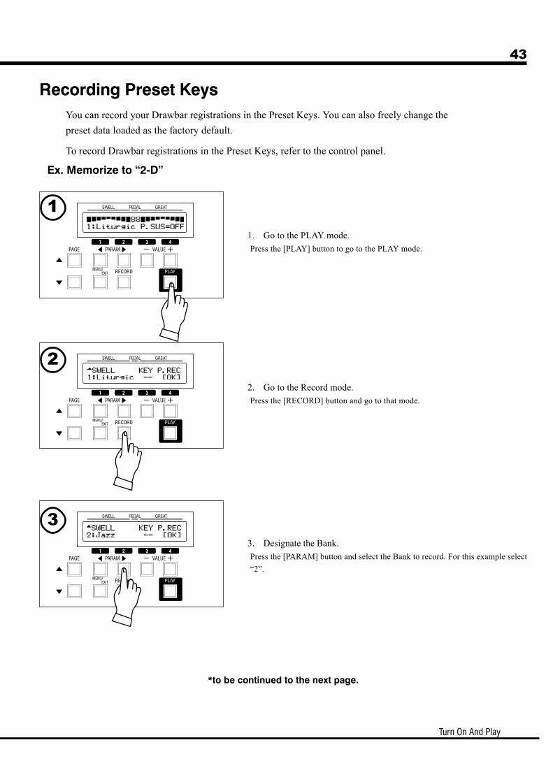
Ex. Memorize to “2-D”
Recording Preset KeysYou can record your Drawbar registrations in the Preset Keys. You can also freely change the
preset data loaded as the factory default.
To record Drawbar registrations in the Preset Keys, refer to the control panel.
1. Go to the PLAY mode.
Press the [PLAY] button to go to the PLAY mode.
2. Go to the Record mode.
Press the [RECORD] button and go to that mode.
3. Designate the Bank.
Press the [PARAM] button and select the Bank to record. For this example select
“2”.
*to be continued to the next page.
1
2
3
44
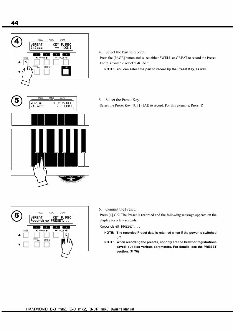
Owner’s Manual
4. Select the Part to record.
Press the [PAGE] button and select either SWELL or GREAT to record the Preset.
For this example select “GREAT”.
NOTE: You can select the part to record by the Preset Key, as well.
5. Select the Preset Key.
Select the Preset Key ([C<] - [A]) to record. For this example, Press [D].
6. Commit the Preset.
Press [4] OK. The Preset is recorded and the following message appears on the
display for a few seconds.
Recording PRESET...
NOTE: The recorded Preset data is retained when if the power is switched
off.
NOTE: When recording the presets, not only are the Drawbar registrations
saved, but also various parameters. For details, see the PRESET
section. (P. 76)
4
5
6
45
Owner’s Manual
SETTING UP

46
Owner’s Manual
SOUND ENGINE STRUCTURE
System structure of this Organ

Setting Up
47
TONE-WHEEL SET
The Tone-wheel Sets are divided into the
Manuals and the Pedal Part. This is to give
the Pedal Part the Decay (= the sound gradu-
ally fading out while pressing the key) or Sus-
tain Effect. (= the sound gradually fading out
after the key is released).
The details are on the next pages.The functions introduced here will be explained
in detail from the next page.
HARMONICS
Harmonic is a pitch of a different ratio to a cer-
tain pitch; for example, the one octave higher
C to the middle C. The more Harmonics, the
brighter and richer sound is obtained.
See the illustrated System Structure of your organ on the left page.
TONE-WHEELSThe sound source or “engine” of Hammond Organ is the Virtual Tone-wheel. Generator.
As on the original B-3, each of the 96 Virtual Tone-wheels are oscillating at a different
pitch. There are NO moving parts inside this organ.
KEYSThe tones of the 96 Virtual Tone-wheels are switched at the keyboard with the “Direct
Analog Keying System” exactly as on the original B-3. There are 9 contacts at each key
responding to each of the 9 Drawbars. When you press a key, the contacts are made to play
the corresponding Drawbars to the pitch of the key depressed.
DRAWBARSThe Drawbars represent simple harmonics. Each bar adjusts the value of each harmonic.
The combinations of different harmonics create a more complex sound.
PERCUSSIONThe Percussion adds a voice with clear attack to the Swell manual. This effect is an essen-
tial part of the Hammond Sound.
VIBRATO AND CHORUSThe classic Hammond “Chorus-Vibrato” gives depth and richness to the organ sound by
slightly varying the pitch (Vibrato) or doubling the voice, just slightly out of tune (Cho-
rus). This effect is a hallmark of the vintage B-3 sound.
NOTE: On this organ the mechanical scanner of the original B-3 is simulated, with no moving
parts.
TUBE PRE-AMPLIFIERA real tube in the pre-amplifier gives this organ the “vintage” sound. By changing the
amount of the drive, you can obtain various tube sound from “clean” (no clipping), to the
hard-distorted fuzzy and raspy “overdrive” popular in rock music.
The Pedal Part is designed not to pass through the tube pre-amp in order to obtain a clear
Bass-Pedal tone.
EFFECTSThe built-in Effects are as follows: an Equalizer for controlling the tonal quality, a Leslie
Effect for giving rotary speaker effects, a Reverb (for giving reverbration), a Tube Buffer
for adding tube “warmth”. (The built-in Leslie Effect does not appear in the signal of the
Leslie 11-pin terminal.)
EFFECT LOOPThe External Effect Loop is located post-internal Effects.

48
Owner’s Manual
HARMONIC DRAWBARS™
The 9 Drawbars (plus 2 for the Pedal) on this organ are used to create the basic sounds. Each
Drawbar is marked with the numbers 1 - 8. If you push back the Drawbar until you cannot see any
number at all, the sound of the Drawbar is not heard. If you pull it out to the fullest position The
sound level is maximum.
The pitch of each Drawbar is as shown above, when the middle C is depressed. The footage
marked (') on the handle end of each Drawbar is originated from the length of pipes on a pipe
organ.
The numbers 1 - 8 on the “bar” portion of each Drawbar indicate the volume of the sound to be
produced as well as the guide to remember Drawbar settings.
Pull the fundamental (8'), the third harmonic (22/3') plus the fifth harmonic (13/5') Drawbars out
completely and play the keyboard. Notice how the sound resembles a clarinet.
If you push the 8' Drawbar half-way, you’ll notice the sound becomes more high-pitched and a bit
“harder”. Now pull the 8' drawbar back out fully and push the 22/3' and 13/5' in halfway. notice how
the sound becomes mellower. Experiment with the Drawbars to obtain your own personal favorite
sounds.
NOTE: You can change the characters of the Drawbars. (P. 72)
No Volume
Full Volume
Setting Up
49
In each Drawbar set, the white Drawbar (8') on the left end correspond to the funda-
mental sound. Each succeeding Drawbar to right controls the next octave harmonic.
WHITE DRAWBARS
The sounds of the black Drawbars, too, play important roles in building rich tones.
Their pitches are fifth and third to the fundamental. They contain the elements of all
different harmonics of such as the sweet and soft horn, mellow strings and so on.
Drawbars for the Pedalboard
Drawbars for the Swell/Great ManualsRelation between the Preset Keys and the
DrawbarsThe two sets of Drawbars on the left-hand side are for the Swell
Manual and the two on the right-hand side are for the Great Manual.
To actuate them, use the Preset Key [A<] or [B] respectively. When
the other [C<] to [A] Preset Keys are selected, the Drawbar regis-
trations are recalled inside the organ, and the tone that plays will
not match the Drawbars physical settings.
NOTE: Even while the Preset Keys [C<<<<<] to [A] are selected, you can
operate the Drawbars and the preset registration will tempo-
rarily change. (P. 52)
The two brown Drawbars on the far left give depth and richness to the sound. The left
16' is one octave lower than the 8', and 51/3' is the third harmonic of the 16' fundamen-
tal.
Normally, the tones are built on the 8' fundamental, but, if you want to add depth to the
tone or to expand the playing range on the manual by one octave, the tones are built on
the 16' fundamental.
The Pedalboard plays the bass line and uses two Drawbars -16' and 8'.
The first Pedal Drawbar produces a tone at 16' pitch for a deep foundation bass, while
the second Pedal Drawbar produces a tone at 8' pitch, or one octave higher.
BLACK DRAWBARS
BROWN DRAWBARS

50
Owner’s Manual
Accomp. Diapason 8' .............. 00 8874 210
Chorus Diapason 8' ................. 00 8686 310
Diapason 8' .............................. 00 7785 321
Echo Diapason 8' .................... 00 4434 210
Harmonic Diapason 16' .......... 85 8524 100
Harmonic Diapason 8' ............ 00 8877 760
Harmonic Diapason 4' ............ 00 0606 045
Horn Diapason 8' .................... 00 8887 480
Open Diapason 8' .................... 01 8866 430
Solo Diapason ......................... 01 8855 331
Wood Diapason 8' ................... 00 7754 321
Cello 8' ..................................... 00 3564 534
Dulciana 8' ............................... 00 7770 000
Gamba 8' I ............................... 00 3484 443
Gemshorn 8' ............................ 00 4741 321
Orchestral String 8' ................. 00 1464 321
Salicional 8' ............................. 00 2453 321
Solo Viola 8' ............................ 00 2474 341
Solo Violin 8' ........................... 00 3654 324
Viola da Gamba 8' ................... 00 2465 432
Violina 4' ................................. 00 0103 064
Violone 16' .............................. 26 3431 000
String family (bow pattern)
Diapason family (check mark pattern)
Drawbar Registration PatternsThe Drawbar Registration is matched by digits. It is easy to remember the typical combinations of
the 9 Drawbars by their forms.
The Drawbar Registrations are grouped into the following 4 patterns:
Flute family (2 step pattern)
Accompaniment Flute 8' I ....... 00 8460 000
Accompaniment Flute 8' II ..... 00 3220 000
Accompaniment Flute 8' III .... 00 8600 000
Chorus of Flutes 16' ................ 80 8605 002
Orchestral Flute 8' ................... 00 3831 000
Piccolo 2' ................................. 00 0006 003
Stopped Flute 8' ...................... 00 5020 000
Tibia 8' ..................................... 00 7030 000
Tibia 4' ..................................... 00 0700 030
Tibia (Theater) 16' .................. 80 8605 004
Wooden Open Flute 8' ............. 00 8840 000
Reed family (triangle pattern)
Bassoon 16' ............................. 44 7000 000
Clarinet 8' ................................ 00 6070 540
English Horn 8' ....................... 00 3682 210
Flugel Horn 8' .......................... 00 5777 530
French Horn ............................. 00 7654 321
Kinura 8' .................................. 00 0172 786
Oboe 8' ..................................... 00 4764 210
Trombone 8' ............................. 01 8777 530
Trumpet 8' ............................... 00 6788 650
Tuba Sonora 8' ........................ 02 7788 640
Vox Humana 8' ........................ 00 4720 123
NOTE: Some of the names on this page may be unfamiliar. They represent the names of types of pipes on a pipe
organ. The “Diapason” is the fundamental type of pipe on a pipe organ.
NOTE: The “Strings” and “Reeds” mentioned here are not analogous to orchestral voices. The names here refer to
types of pipes found in a pipe organ and the sounds are not meant to sound as actual violins, trumpets,
oboes, etc.
Setting Up
51
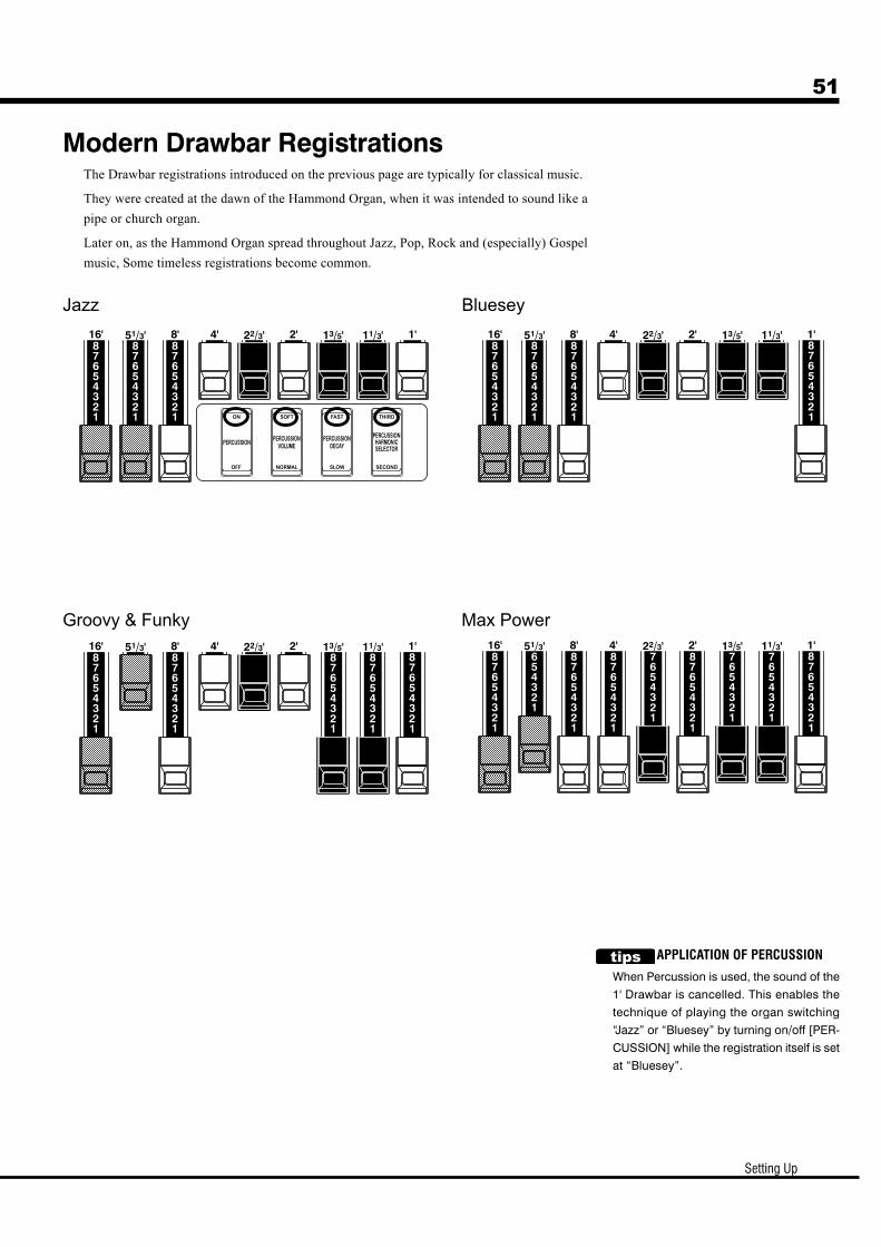
Modern Drawbar RegistrationsThe Drawbar registrations introduced on the previous page are typically for classical music.
They were created at the dawn of the Hammond Organ, when it was intended to sound like a
pipe or church organ.
Later on, as the Hammond Organ spread throughout Jazz, Pop, Rock and (especially) Gospel
music, Some timeless registrations become common.
Jazz Bluesey
Groovy & Funky Max Power
APPLICATION OF PERCUSSION
When Percussion is used, the sound of the
1' Drawbar is cancelled. This enables the
technique of playing the organ switching
“Jazz” or “Bluesey” by turning on/off [PER-
CUSSION] while the registration itself is set
at “Bluesey”.
52
Owner’s Manual
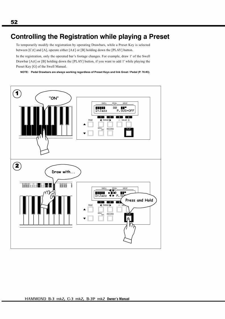
Controlling the Registration while playing a PresetTo temporarily modify the registration by operating Drawbars, while a Preset Key is selected
between [C<] and [A], operate either [A<] or [B] holding down the [PLAY] button.
In the registration, only the operated bar’s footage changes. For example, draw 1' of the Swell
Drawbar [A<] or [B] holding down the [PLAY] button, if you want to add 1' while playing the
Preset Key [G] of the Swell Manual.
NOTE: Pedal Drawbars are always working regardless of Preset Keys and link Great / Pedal (P. 76 #3).
22222
11111“ON”
Press and Hold
Draw with...
Setting Up
53PERCUSSION
Notes“Percussion does not sound!”
The factory default setting: Percussion will not sound except at the Preset Key [B] (See left).
NOTE: You can set any Preset Key to sound Percussion. (P. 77 #7)
DRAWBAR CANCELWhile [PERCUSSION] is on, 1' of the Swell Drawbars is disabled.
NOTE: You can set to play 1' Drawbar, while Percussion is on. (P. 74 #5)
SINGLE TRIGGERIf you play legato on this organ, only the first note of Percussion is output, and it does not trigger
again unless you fully release all keys held on the Swell Manual.
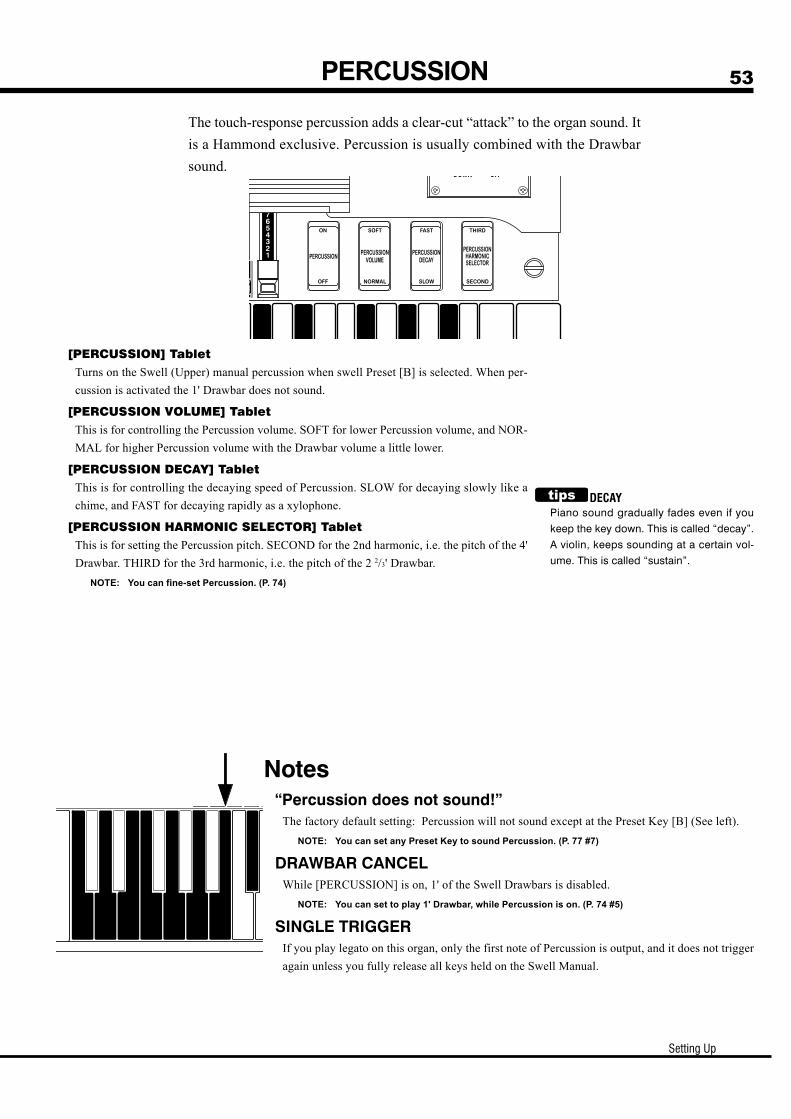
[PERCUSSION] TabletTurns on the Swell (Upper) manual percussion when swell Preset [B] is selected. When per-
cussion is activated the 1' Drawbar does not sound.
[PERCUSSION VOLUME] TabletThis is for controlling the Percussion volume. SOFT for lower Percussion volume, and NOR-
MAL for higher Percussion volume with the Drawbar volume a little lower.
[PERCUSSION DECAY] TabletThis is for controlling the decaying speed of Percussion. SLOW for decaying slowly like a
chime, and FAST for decaying rapidly as a xylophone.
[PERCUSSION HARMONIC SELECTOR] TabletThis is for setting the Percussion pitch. SECOND for the 2nd harmonic, i.e. the pitch of the 4'
Drawbar. THIRD for the 3rd harmonic, i.e. the pitch of the 2 2/3' Drawbar.
NOTE: You can fine-set Percussion. (P. 74)
The touch-response percussion adds a clear-cut “attack” to the organ sound. It
is a Hammond exclusive. Percussion is usually combined with the Drawbar
sound.
DECAYPiano sound gradually fades even if you
keep the key down. This is called “decay”.
A violin, keeps sounding at a certain vol-
ume. This is called “sustain”.
54
Owner’s Manual
VIBRATO AND CHORUS
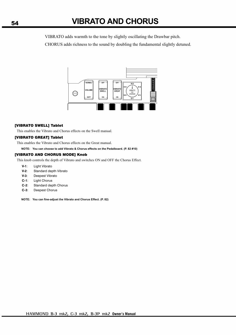
VIBRATO adds warmth to the tone by slightly oscillating the Drawbar pitch.
CHORUS adds richness to the sound by doubling the fundamental slightly detuned.
[VIBRATO SWELL] TabletThis enables the Vibrato and Chorus effects on the Swell manual.
[VIBRATO GREAT] TabletThis enables the Vibrato and Chorus effects on the Great manual.
NOTE: You can choose to add Vibrato & Chorus effects on the Pedalboard. (P. 82 #10)
[VIBRATO AND CHORUS MODE] KnobThis knob controls the depth of Vibrato and switches ON and OFF the Chorus Effect.
V-1: Light Vibrato
V-2: Standard depth Vibrato
V-3: Deepest Vibrato
C-1: Light Chorus
C-2: Standard depth Chorus
C-3: Deepest Chorus
NOTE: You can fine-adjust the Vibrato and Chorus Effect. (P. 82)
Setting Up
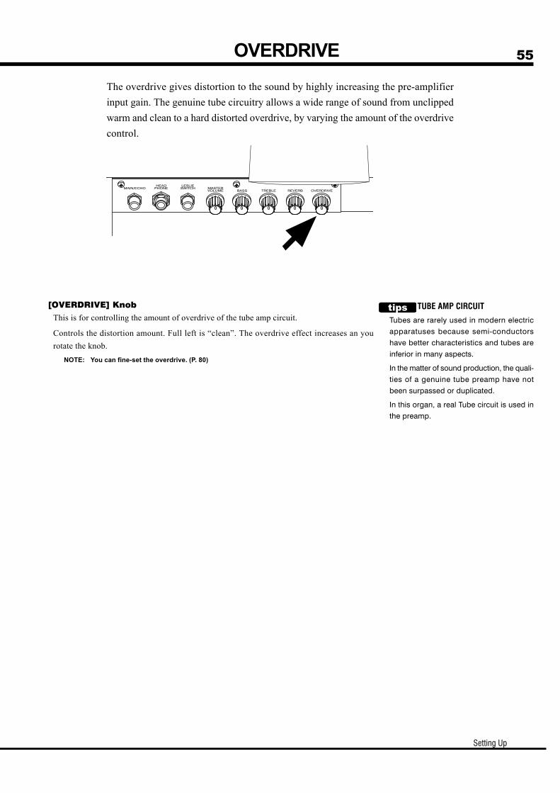
55OVERDRIVE
The overdrive gives distortion to the sound by highly increasing the pre-amplifier
input gain. The genuine tube circuitry allows a wide range of sound from unclipped
warm and clean to a hard distorted overdrive, by varying the amount of the overdrive
control.
[OVERDRIVE] KnobThis is for controlling the amount of overdrive of the tube amp circuit.
Controls the distortion amount. Full left is “clean”. The overdrive effect increases an you
rotate the knob.
NOTE: You can fine-set the overdrive. (P. 80)
TUBE AMP CIRCUIT
Tubes are rarely used in modern electric
apparatuses because semi-conductors
have better characteristics and tubes are
inferior in many aspects.
In the matter of sound production, the quali-
ties of a genuine tube preamp have not
been surpassed or duplicated.
In this organ, a real Tube circuit is used in
the preamp.
56
Owner’s Manual
LESLIE
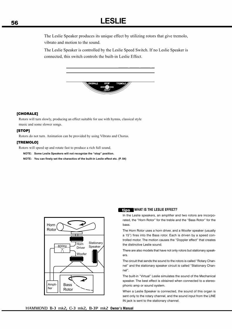
WHAT IS THE LESLIE EFFECT?
In the Leslie speakers, an amplifier and two rotors are incorpo-
rated, the “Horn Rotor” for the treble and the “Bass Rotor” for the
bass.
The Horn Rotor uses a horn driver, and a Woofer speaker (usually
a 15”) fires into the Bass rotor. Each is driven by a speed con-
trolled motor. The motion causes the “Doppler effect” that creates
the distinctive Leslie sound.
There are also models that have not only rotors but stationary speak-
ers.
The circuit that sends the sound to the rotors is called “Rotary Chan-
nel” and the stationary speaker circuit is called “Stationary Chan-
nel”.
The built-in “Virtual” Leslie simulates the sound of the Mechanical
speaker. The best effect is obtained when connected to a stereo-
phonic amp or sound system.
When a Leslie Speaker is connected, the sound of this organ is
sent only to the rotary channel, and the sound input from the LINE
IN jack is sent to the stationary channel.
[CHORALE]Rotors will turn slowly, producing an effect suitable for use with hymns, classical style
music and some slower songs.
[STOP]Rotors do not turn. Animation can be provided by using Vibrato and Chorus.
[TREMOLO]Rotors will speed up and rotate fast to produce a rich full sound.
NOTE: Some Leslie Speakers will not recognize the “stop” position.
NOTE: You can finely set the charactics of the built-in Leslie effect etc. (P. 84)
The Leslie Speaker produces its unique effect by utilizing rotors that give tremolo,
vibrato and motion to the sound.
The Leslie Speaker is controlled by the Leslie Speed Switch. If no Leslie Speaker is
connected, this switch controls the built-in Leslie Effect.

Setting Up
57EQUALIZER, REVERB
The Equalizer and the Reverb add a final touch to the tone.
The Equalizer regulates the tonal quality. The Reverb adds the effect of playing in a
concert hall.
You control their basic functions on the panel under the left side of the keydesk.
Equalizer
Reverb
[BASS] KnobBASS is assigned here at the time of shipment from the factory. This increases/decreases the bass
sound. About ±9dB is adjustable at 100Hz.
[TREBLE] KnobTONE is assigned here at the time of shipment from the factory. It increases/decreases the treble
sound. About -9 to +3dB is adjustable at 10kHz.
NOTE: The Equalizer actually has 3 bands and 1 tonal function, and one function is assignable to each
BASS, TREBLE knob. (P. 88)
NOTE: The “Tone” function here refers to the unique internal control on the vintage B-3 that gently cut the
treble. This is a different function than the “Treble” EQ.
[REVERB] KnobThis is for controlling the depth of the reverb effect. It gives no reverb effect at full counter-clockwise.
The reverb gets deeper as it is turned further clockwise.
NOTE: You can finely set the reverb. (P. 89)
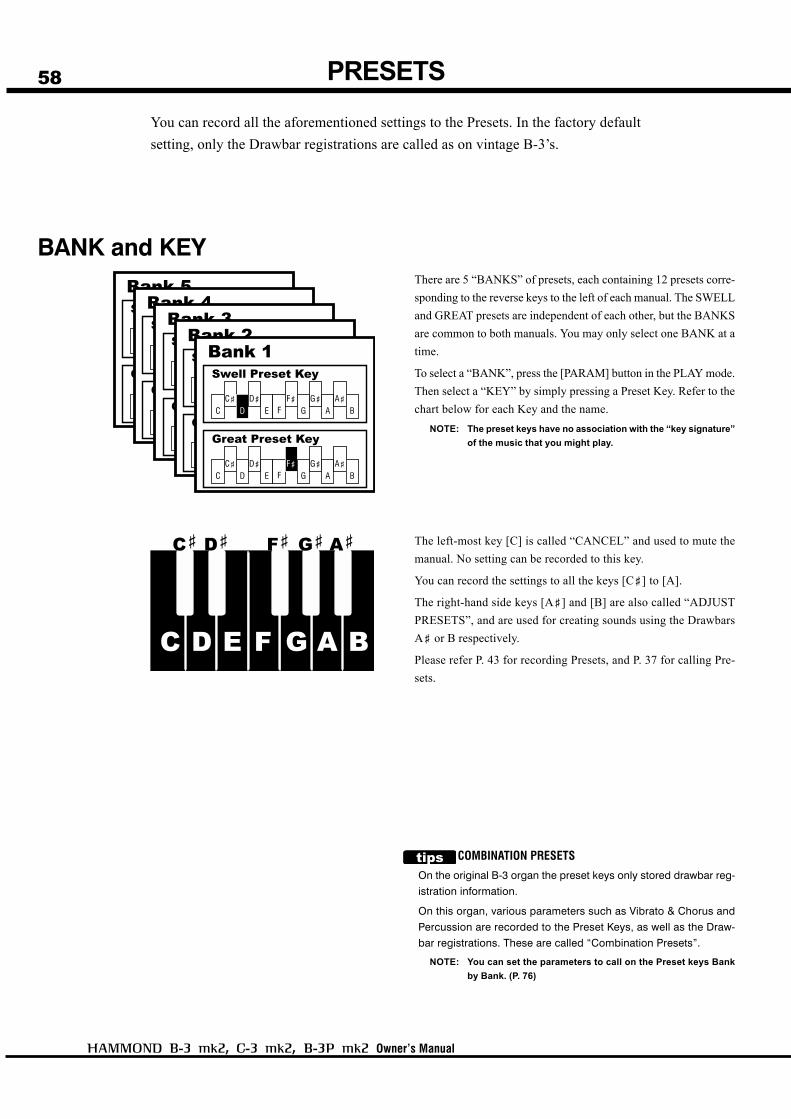
58
Owner’s Manual
PRESETS
You can record all the aforementioned settings to the Presets. In the factory default
setting, only the Drawbar registrations are called as on vintage B-3’s.
BANK and KEYThere are 5 “BANKS” of presets, each containing 12 presets corre-
sponding to the reverse keys to the left of each manual. The SWELL
and GREAT presets are independent of each other, but the BANKS
are common to both manuals. You may only select one BANK at a
time.
To select a “BANK”, press the [PARAM] button in the PLAY mode.
Then select a “KEY” by simply pressing a Preset Key. Refer to the
chart below for each Key and the name.
NOTE: The preset keys have no association with the “key signature”
of the music that you might play.
The left-most key [C] is called “CANCEL” and used to mute the
manual. No setting can be recorded to this key.
You can record the settings to all the keys [C<] to [A].
The right-hand side keys [A<] and [B] are also called “ADJUST
PRESETS”, and are used for creating sounds using the Drawbars
A< or B respectively.
Please refer P. 43 for recording Presets, and P. 37 for calling Pre-
sets.
COMBINATION PRESETS
On the original B-3 organ the preset keys only stored drawbar reg-
istration information.
On this organ, various parameters such as Vibrato & Chorus and
Percussion are recorded to the Preset Keys, as well as the Draw-
bar registrations. These are called “Combination Presets”.
NOTE: You can set the parameters to call on the Preset keys Bank
by Bank. (P. 76)

Setting Up
59
Using Plural Presets at the Same Time
When pressing a Preset Key, the previously selected key is released.
However, it does not mean you can not select more than one key.
If you select more than one Preset Key at the same time, the regis-
trations recorded for all those keys are mixed. Try this.
If the other parameters than the registrations in the Preset Function
Mode are contained in the preset, the contents of the key pressed
last are called out.
In case you select all the Preset Keys by mistake and the Preset
Keys do not function, press the [C] Preset Key, to release all of the
Preset Keys.
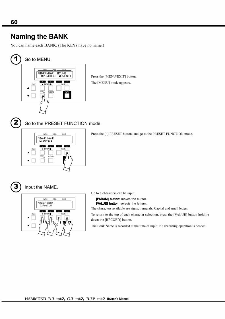
60
Owner’s Manual
Naming the BANKYou can name each BANK. (The KEYs have no name.)
1 Go to MENU.
Press the [MENU/EXIT] button.
The [MENU] mode appears.
2 Go to the PRESET FUNCTION mode.
Press the [4] PRESET button, and go to the PRESET FUNCTION mode.
3 Input the NAME.Up to 8 characters can be input.
[P[P[P[P[PARAM] buttonARAM] buttonARAM] buttonARAM] buttonARAM] button: moves the cursor.
[V[V[V[V[VALALALALALUE] buttonUE] buttonUE] buttonUE] buttonUE] button: selects the letters.
The characters available are signs, numerals, Capital and small letters.
To return to the top of each character selection, press the [VALUE] button holding
down the [RECORD] button.
The Bank Name is recorded at the time of input. No recording operation is needed.
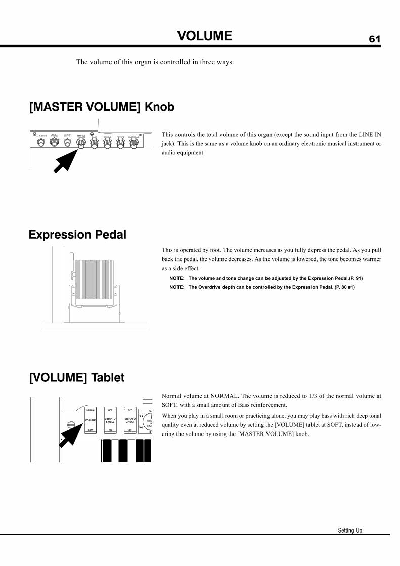
Setting Up
61VOLUME
The volume of this organ is controlled in three ways.
Expression PedalThis is operated by foot. The volume increases as you fully depress the pedal. As you pull
back the pedal, the volume decreases. As the volume is lowered, the tone becomes warmer
as a side effect.
NOTE: The volume and tone change can be adjusted by the Expression Pedal.(P. 91)
NOTE: The Overdrive depth can be controlled by the Expression Pedal. (P. 80 #1)
[VOLUME] TabletNormal volume at NORMAL. The volume is reduced to 1/3 of the normal volume at
SOFT, with a small amount of Bass reinforcement.
When you play in a small room or practicing alone, you may play bass with rich deep tonal
quality even at reduced volume by setting the [VOLUME] tablet at SOFT, instead of low-
ering the volume by using the [MASTER VOLUME] knob.
[MASTER VOLUME] Knob
This controls the total volume of this organ (except the sound input from the LINE IN
jack). This is the same as a volume knob on an ordinary electronic musical instrument or
audio equipment.
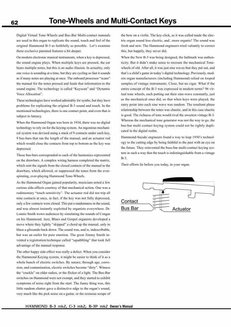
62
Owner’s Manual
Tone-Wheels and Multi-Contact Keys
Digital Virtual Tone-Wheels and Bus-Bar Multi-contact manuals
are used in this organ to replicate the sound, touch and feel of the
original Hammond B-3 as faithfully as possible. Let’s examine
these exclusive patented features a bit deeper.
On modern electronic musical instruments, when a key is depressed,
the sound engine plays. When multiple keys are pressed, the ear
hears multiple notes, but this is an audio illusion. In actuality, only
one voice is sounding at a time, but they are cycling so fast it sounds
as if many notes are playing at once. The onboard processor “scans”
the manual for the notes pressed and feeds that information to the
sound engine. The technology is called “Keyscan” and “Dynamic
Voice Allocation”.
These technologies have worked admirably for synths, but they have
problems for replicating the original B-3 sound and touch. In the
mentioned technologies, there is one contact point, and even that is
subject to latency.
When the Hammond Organ was born in 1934, there was no digital
technology to rely on for the keying system. An ingenious mechani-
cal system was devised using a stack of 9 contacts under each key,
9 bus-bars that ran the length of the manual, and an actuator rod
which would close the contacts from top to bottom as the key was
depressed.
Those bus-bars corresponded to each of the harmonics represented
on the drawbars. A complex wiring harness completed the matrix,
which sent the signals from the closed contacts of the manual to the
drawbars, which allowed, or suppressed the tones from the ever-
spinning, ever-playing Hammond Tone-Wheels.
As the Hammond Organ gained popularity, musicians noted a few
curious side-effects courtesy of that mechanical action. One was a
rudimentary “touch sensitivity”. The actuator rod did not trip all
nine contacts at once, in fact, if the key was not fully depressed,
only a few contacts were closed. This put a randomness in the sound,
and was almost instantly exploited by organists everywhere. Dr.
Lonnie Smith wows audiences by simulating the sounds of Congas
on his Hammond. Jazz, Blues and Gospel organists developed a
move where they lightly “skipped” a chord up the manual, only to
blaze a glissando back down. The sound was, and is, indescribable,
but was an outlet for pure emotion. The great Jimmy Smith in-
vented a registration/technique called “squabbling” that took full
advantage of the manual response.
The other happy side-effect was really a defect. When you consider
the Hammond Keying system, it might be easier to think of it as a
whole bunch of electric switches. By nature; through age, corro-
sion, and contamination, electric switches become “dirty”. Witness
the “crackle” on older radios, or the flicker of a light. The Bus-Bar
switches on Hammond were not exempt, and they started to exhibit
symptoms of noise right from the start. The funny thing was, this
little random chatter gave a distinctive edge to the organ’s sound,
very much like the pick noise on a guitar, or the resinous scrape of
the bow on a violin. The key-click, as it was called made the elec-
tric organ sound less electric, and...more organic! The sound was
fresh and new. The Hammond engineers tried valiantly to correct
this, but happily, they never did.
When the New B-3 was being designed, the hallmark was authen-
ticity. But it didn’t make sense to recreate the mechanical Tone-
wheels of old. After all, it was just sine waves that they put out, and
that’s a child’s game in today’s digital technology. Previously, mod-
ern organ manufacturers (including Hammond) relied on looped
samples of vintage instruments. Close, but no cigar. What if the
entire concept of the B-3 was expressed in modern terms? 96 vir-
tual tone wheels, each putting out their sine-wave constantly, just
as the mechanical ones did, so that when keys were played, the
entry point into each sine wave was random. The resultant phase
relationship between the tones was chaotic, and in this case chaotic
is good. The richness of tone would rival the sweetest vintage B-3.
Whereas the mechanical tone generator was not the way to go, the
bus-bar multi contact keying system could not be rightly dupli-
cated in the digital realm.
Hammond-Suzuki engineers found a way to leap 1930’s technol-
ogy to the cutting edge by being faithful to the past with an eye on
the future. They reinvented the buss-bar multi-contact keying sys-
tem in such a way that the touch is indistinguishable from a vintage
B-3.
Their efforts lie before you today, in your organ.
63
Owner’s Manual
USING THECONTROL PANEL
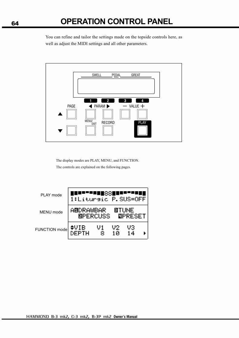
64
Owner’s Manual
OPERATION CONTROL PANEL
You can refine and tailor the settings made on the topside controls here, as
well as adjust the MIDI settings and all other parameters.
The display modes are PLAY, MENU, and FUNCTION.
The controls are explained on the following pages.
PLAY mode
MENU mode
FUNCTION mode
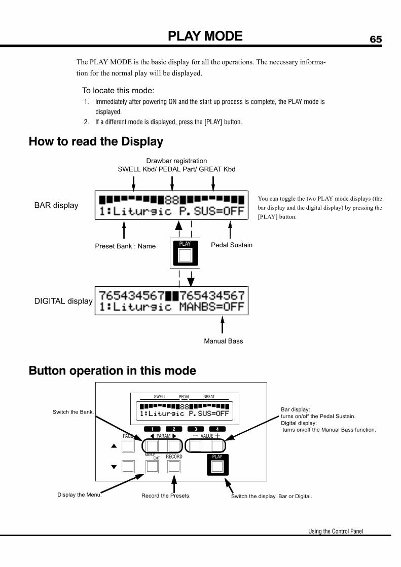
Using the Control Panel
65PLAY MODE
The PLAY MODE is the basic display for all the operations. The necessary informa-
tion for the normal play will be displayed.
To locate this mode:1. Immediately after powering ON and the start up process is complete, the PLAY mode is
displayed.
2. If a different mode is displayed, press the [PLAY] button.
How to read the Display
BAR display
DIGITAL display
You can toggle the two PLAY mode displays (the
bar display and the digital display) by pressing the
[PLAY] button.
Drawbar registrationSWELL Kbd/ PEDAL Part/ GREAT Kbd
Preset Bank : Name Pedal Sustain
Manual Bass
Button operation in this mode
Switch the Bank.
Display the Menu. Record the Presets. Switch the display, Bar or Digital.
Bar display:turns on/off the Pedal Sustain.Digital display: turns on/off the Manual Bass function.
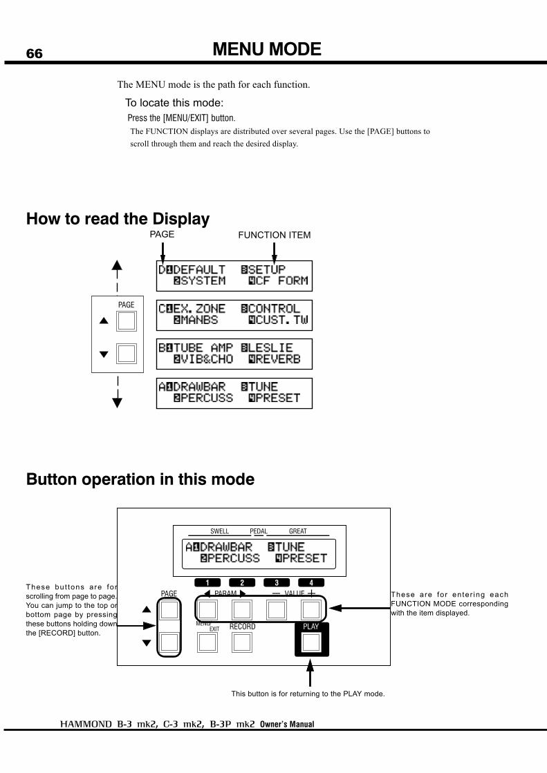
66
Owner’s Manual
MENU MODE
The MENU mode is the path for each function.
To locate this mode:Press the [MENU/EXIT] button.The FUNCTION displays are distributed over several pages. Use the [PAGE] buttons to
scroll through them and reach the desired display.
How to read the DisplayPAGE FUNCTION ITEM
Button operation in this mode
These but tons are fo rscrolling from page to page.You can jump to the top orbottom page by pressingthese buttons holding downthe [RECORD] button.
This button is for returning to the PLAY mode.
These are for enter ing eachFUNCTION MODE correspondingwith the item displayed.

Using the Control Panel
67FUNCTION MODE
CURSOR
In the display window of this organ, the
CURSOR is displayed by flashing the cur-
rent value.
The FUNCTION MODE is where you adjust the various parameters of the organ.
The displays generally follow the same format.
How to read the Display
Button operation in this mode
These buttons are for scrolling withinthe pages of the display.You can jump to the top or bottompage by pressing these buttons withholding down the [RECORD] Button.
Increases or decreases the value of theParameter indicated by the flashing CURSOR.Holding it increases (or decreases) the valuecontinuously.Pressing it while holding the [RECORD] buttonincreases (or decreases) the value quickly.
Return to the PLAY mode.
This indicates there are PAGEsabove (or below). PARAMETER
This indicates there is another sectionto this page on the right (or on the left).
PAGENAME
VALUE CURSOR(Flashing VALUE)
These buttons are used to move the CURSOR rightor left for selecting the PARAMETER to change.The CURSOR moves to the edge of the display andon to the next page (on the right or left), if there isone.Pressing this button holding [RECORD] button, youcan move to the right or left page regardless of wherethe cursor is.

68
Owner’s Manual
Search for the VIB&CHO page, using the [PAGE] button.
“VIB&CHO” is on PAGE B. Select PAGE [B].
Example: Increase the depth of Vibrato at [V-3].
Press the [2] button for “VIB&CHO”.
This calls the first page of the Vibrato and Chorus function mode.
Locate the MENU Mode.1
2
3
Press the [MENU/EXIT] button.
The MENU mode is displayed.
Selet the PAGE.
Press the Number button.
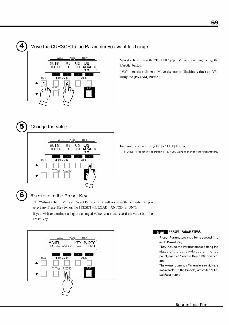
Using the Control Panel
69
Move the CURSOR to the Parameter you want to change.
Change the Value.
Vibrato Depth is on the “DEPTH” page. Move to that page using the
[PAGE] button.
“V3” is on the right end. Move the cursor (flashing value) to “V3”
using the [PARAM] button.
Increase the value, using the [VALUE] button.
NOTE: Repeat the operation 1 - 5, if you want to change other parameters.
Record in to the Preset Key.The “Vibrato Depth V3” is a Preset Parameter, it will revert to the set value, if you
select any Preset Key (when the PRESET - P. LOAD - ANI/OD is “ON”).
If you wish to continue using the changed value, you must record the value into the
Preset Key.
4
5
6
PRESET PARAMETERS
Preset Parameters may be recorded into
each Preset Key.
They include the Parameters for setting the
status of the buttons/knobs on the top
panel, such as “Vibrato Depth V3” and oth-
ers.
The overall common Parameters (which are
not included in the Presets) are called “Glo-
bal Parameters.”
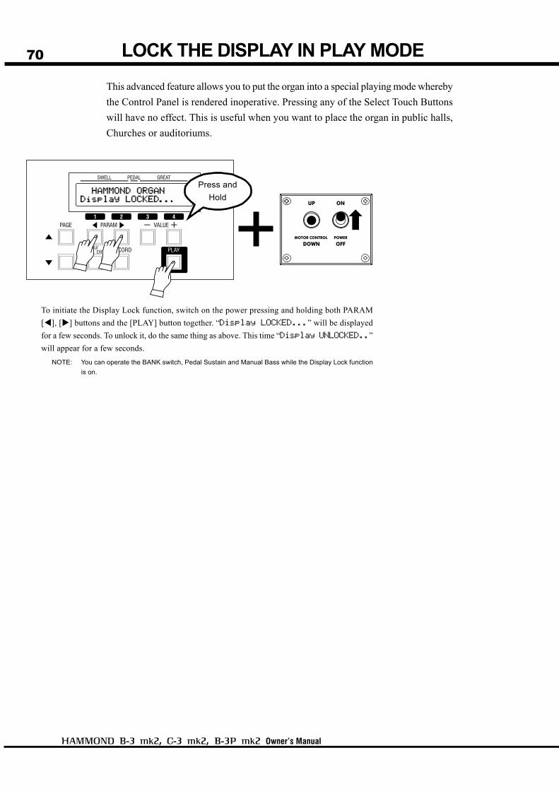
70
Owner’s Manual
LOCK THE DISPLAY IN PLAY MODE
To initiate the Display Lock function, switch on the power pressing and holding both PARAM
[ ], [ ] buttons and the [PLAY] button together. “Display LOCKED...” will be displayed
for a few seconds. To unlock it, do the same thing as above. This time “Display UNLOCKED..”
will appear for a few seconds.
NOTE: You can operate the BANK switch, Pedal Sustain and Manual Bass while the Display Lock function
is on.
This advanced feature allows you to put the organ into a special playing mode whereby
the Control Panel is rendered inoperative. Pressing any of the Select Touch Buttons
will have no effect. This is useful when you want to place the organ in public halls,
Churches or auditoriums.
Press and
Hold
71
Owner’s Manual
SETTING THEPARAMETERS

72
Owner’s Manual
In this mode, you set the Drawbar Parameters.
To locate this mode:Press the [MENU/EXIT] button and display MENU, press the [PAGE] button, and select
PAGE A, and choose [1] DRAWBAR.
LEAKAGE NOISE
On the original B-3, while the sound created by a cer-
tain tone-wheel goes through various circuits, the
sounds of the other plural tone-wheels are mixed. This
is called Leakage Noise. Leakage noise itself is unnec-essary for synthesizing pure sounds. However, it is
accepted rather as one of the unique characteristics of
Hammond Organs.
Leakage Noise allows you to make finer adjustment.
(P. 92)
FOLD-BACK
As the number of the tonewheels was limited on the
original B-3, the organs were designed to repeat the
same octave in the upper-most or lower-most range.
This feature of this organ will simulate that.
Setting the SWELL and GREAT Manual1. TONE-WHEELS
Select the TONE-WHEEL SET (waveform) for the manuals.
BTBTBTBTBType1ype1ype1ype1ype1:Traditional tone-wheel sound of the original B-3. Leakage noise is included inthe waveform. You can not adjust the volume of the inherent leakage noise.
BTBTBTBTBType2ype2ype2ype2ype2:Traditional tone-wheel sound of the original B-3. Leakage noise is not includedin the waveform. You can add and adjust the volume of leakage noise.
MellowMellowMellowMellowMellow: Transparent sine wave
2. LEAKAGEThis is for setting the volume of Leakage Noise.
Setting Range is 0 to 127. The more you increase the value, the louder gets the volume.
3. FOLD-BACK - LOWThis allows you to set which key the FOLD BACK of the 16' Drawbar starts. (Fold-back:
Repeating the same octave in a certain range on the manual.)
The first key (= the far left key on the manual, next to the Preset Keys) is displayed as
“1C”. The setting range is 1C - 2C.
4. FOLD-BACK - HIGHThis allows you to set which key the FOLD BACK of the 1' Drawbar starts (= repeat the
same octave) in the upper-most range. The set range is 4G - 5C.
NOTE: The FOLD-BACK sets the 1' and also 11/3', 13/5', 2' and 22/3' Drawbars.
TONE-WHEEL SET
Each Tone-wheel Set allows you to make fine adjust-
ment. (P. 92)
DRAWBAR
1
32 4
76
5
8 9 1011
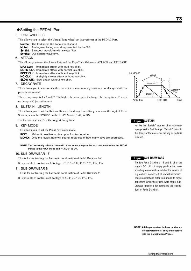
73
Setting the Parameters
SUSTAIN
Not like the “Sustain” segment of a synth enve-
lope generator. On this organ “Sustain” refers to
the decay of the note after the key or pedal is
released.
Setting the PEDAL Part5. TONE-WHEELS
This allows you to select the Virtual Tone-wheel set (waveform) of the PEDAL Part.
NormalNormalNormalNormalNormal: The traditional B-3 Tone-wheel soundMutedMutedMutedMutedMuted: Analog-oscillating sound represented by the X-5.Synth1Synth1Synth1Synth1Synth1: Sawtooth waveform with sweep filter.Synth2Synth2Synth2Synth2Synth2: Dull square waveform.
6. ATTACKThis allows you to set the Attack Rate and the Key-Click Volume at ATTACK and RELEASE.
MAX CLKMAX CLKMAX CLKMAX CLKMAX CLK: Immediate attack with loud key-click.NORM CLKNORM CLKNORM CLKNORM CLKNORM CLK: Immediate attack with normal key-click.SOFSOFSOFSOFSOFT CLKT CLKT CLKT CLKT CLK: Immediate attack with soft key-click.NO CLKNO CLKNO CLKNO CLKNO CLK: A slightly slower attack without key-click.SLSLSLSLSLOW AOW AOW AOW AOW ATKTKTKTKTK: Slow attack without key-click.
7. DECAY RATEThis allows you to choose whether the voice is continuously sustained, or decays while the
pedal is depressed.
The setting range is 1 - 5 and C. The higher the value gets, the longer the decay time. There is
no decay at C (=continuous).
8. SUSTAIN - LENGTHThis allows you to set the Release Rate (= the decay time after you release the key) of Pedal
Sustain, when the “P.SUS” on the PLAY Mode (P. 42) is ON.
1 is the shortest, and 5 is the longest decay time.
9. KEY MODEThis allows you to set the Pedal Part voice mode.
POLPOLPOLPOLPOLYYYYY: Makes it possible to play up to 8 notes together.MONOMONOMONOMONOMONO: Only the lowest note will sound, regarless of how many keys are depressed.
NOTE: The previously released note will be cut when you play the next one, even when the PEDAL
Part is in the POLY mode and “P. SUS” is ON.
10. SUB-DRAWBAR 16'This is for controlling the harmonic combination of Pedal Drawbar 16'.
It is possible to control each footage of 16', 51/3', 8', 4', 22/3', 2', 13/5', 11/3'.
11. SUB-DRAWBAR 8'This is for controlling the harmonic combination of Pedal Drawbar 8'.
It is possible to control each footage of 8', 4', 22/3', 2', 13/5', 11/3'.
NOTE: All the parameters in these modes are
Preset Parameters. They are recorded
into the Combination Preset.
SUB-DRAWBARS
The two Pedal Drawbars, 16' and 8', of on the
original B-3, did not simply produce the corre-
sponding tone-wheel sounds but the sounds of
registrations composed of several harmonics.
These registrations differ from model to model
depending when the organs were made. Sub-
Drawbar function is for controlling the registra-
tions of Pedal Drawbars.
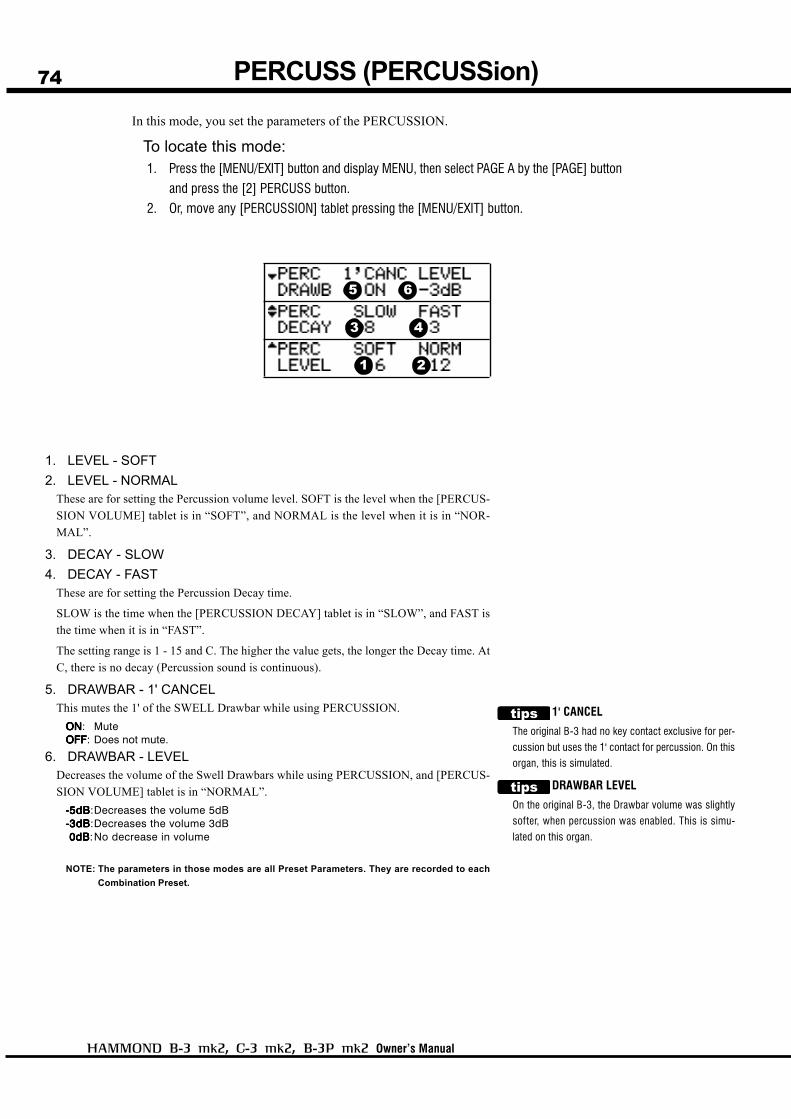
74
Owner’s Manual
In this mode, you set the parameters of the PERCUSSION.
To locate this mode:1. Press the [MENU/EXIT] button and display MENU, then select PAGE A by the [PAGE] button
and press the [2] PERCUSS button.
2. Or, move any [PERCUSSION] tablet pressing the [MENU/EXIT] button.
1. LEVEL - SOFT
2. LEVEL - NORMALThese are for setting the Percussion volume level. SOFT is the level when the [PERCUS-
SION VOLUME] tablet is in “SOFT”, and NORMAL is the level when it is in “NOR-
MAL”.
3. DECAY - SLOW
4. DECAY - FASTThese are for setting the Percussion Decay time.
SLOW is the time when the [PERCUSSION DECAY] tablet is in “SLOW”, and FAST is
the time when it is in “FAST”.
The setting range is 1 - 15 and C. The higher the value gets, the longer the Decay time. At
C, there is no decay (Percussion sound is continuous).
5. DRAWBAR - 1' CANCELThis mutes the 1' of the SWELL Drawbar while using PERCUSSION.
ONONONONON: MuteOFFOFFOFFOFFOFF: Does not mute.
6. DRAWBAR - LEVELDecreases the volume of the Swell Drawbars while using PERCUSSION, and [PERCUS-
SION VOLUME] tablet is in “NORMAL”.
-5dB-5dB-5dB-5dB-5dB:Decreases the volume 5dB-3dB-3dB-3dB-3dB-3dB:Decreases the volume 3dB 0dB 0dB 0dB 0dB 0dB:No decrease in volume
NOTE: The parameters in those modes are all Preset Parameters. They are recorded to each
Combination Preset.
1' CANCEL
The original B-3 had no key contact exclusive for per-
cussion but uses the 1' contact for percussion. On this
organ, this is simulated.
DRAWBAR LEVEL
On the original B-3, the Drawbar volume was slightly
softer, when percussion was enabled. This is simu-
lated on this organ.
PERCUSS (PERCUSSion)
1 2
3 4
5 6
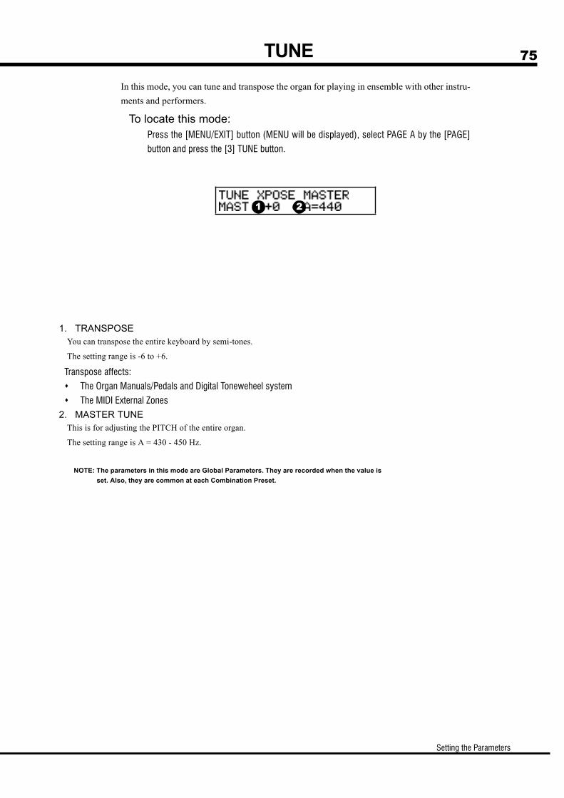
75
Setting the Parameters
TUNE
In this mode, you can tune and transpose the organ for playing in ensemble with other instru-
ments and performers.
To locate this mode:Press the [MENU/EXIT] button (MENU will be displayed), select PAGE A by the [PAGE]
button and press the [3] TUNE button.
1. TRANSPOSEYou can transpose the entire keyboard by semi-tones.
The setting range is -6 to +6.
Transpose affects:
The Organ Manuals/Pedals and Digital Toneweheel system
The MIDI External Zones
2. MASTER TUNEThis is for adjusting the PITCH of the entire organ.
The setting range is A = 430 - 450 Hz.
NOTE: The parameters in this mode are Global Parameters. They are recorded when the value is
set. Also, they are common at each Combination Preset.
1 2
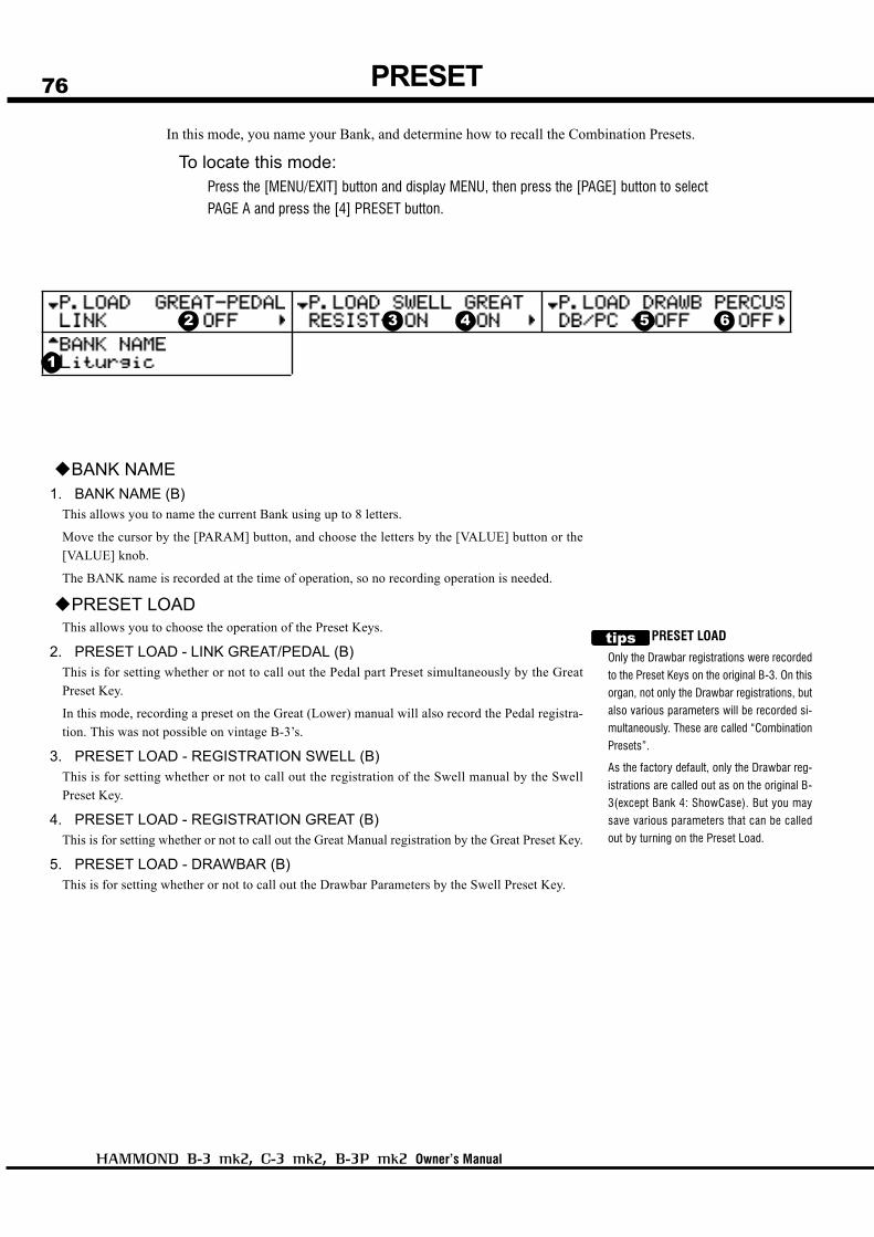
76
Owner’s Manual
In this mode, you name your Bank, and determine how to recall the Combination Presets.
To locate this mode:Press the [MENU/EXIT] button and display MENU, then press the [PAGE] button to select
PAGE A and press the [4] PRESET button.
PRESET
BANK NAME1. BANK NAME (B)
This allows you to name the current Bank using up to 8 letters.
Move the cursor by the [PARAM] button, and choose the letters by the [VALUE] button or the
[VALUE] knob.
The BANK name is recorded at the time of operation, so no recording operation is needed.
PRESET LOADThis allows you to choose the operation of the Preset Keys.
2. PRESET LOAD - LINK GREAT/PEDAL (B)This is for setting whether or not to call out the Pedal part Preset simultaneously by the Great
Preset Key.
In this mode, recording a preset on the Great (Lower) manual will also record the Pedal registra-
tion. This was not possible on vintage B-3’s.
3. PRESET LOAD - REGISTRATION SWELL (B)This is for setting whether or not to call out the registration of the Swell manual by the Swell
Preset Key.
4. PRESET LOAD - REGISTRATION GREAT (B)This is for setting whether or not to call out the Great Manual registration by the Great Preset Key.
5. PRESET LOAD - DRAWBAR (B)This is for setting whether or not to call out the Drawbar Parameters by the Swell Preset Key.
PRESET LOAD
Only the Drawbar registrations were recorded
to the Preset Keys on the original B-3. On this
organ, not only the Drawbar registrations, but
also various parameters will be recorded si-
multaneously. These are called “Combination
Presets”.
As the factory default, only the Drawbar reg-
istrations are called out as on the original B-
3(except Bank 4: ShowCase). But you may
save various parameters that can be called
out by turning on the Preset Load.
1
2 3 4 5 6

77
Setting the Parameters
6. PRESET LOAD - PERCUSSION (B)This is for setting whether or not to permit the Percussion division to play while the selection of the
Swell Preset Key is other than [B] and whether to call out the tablets of Percussion, or Percussion
Parameter by the Swell Preset Key.
7. PRESET LOAD - MANUAL BASS (B)This is for setting whether or not to call out the Manual Bass ON/OFF, and upper limit by the Great
Preset Key.
8. PRESET LOAD - EXTERNAL ZONE SWELL (B)This is for setting whether or not to call out the External Zone Parameter of the Swell manual by the
Swell Preset Key.
9. PRESET LOAD - EXTERNAL ZONE GREAT (B)This is for setting whether or not to call out the External Zone Parameters of the Great manual by the
Great Preset key. The External Zone Parameters of the Pedal part is also called out, if the Link-Great/
Pedal is on.
10. PRESET LOAD - EQUALIZER/REVERB (B)This is for setting whether or not to call out the Parameters of the Equalizer and Reverb by the Swell
Preset key.
11. PRESET LOAD - ANIMATION/OVERDRIVE (B)This is for setting whether or not to call out the tablets and parameters of Vibrato, Leslie and Over-
drive by the Swell Preset Key.
NOTE: Each Parameter (B) of Preset Load is a Bank Parameter. It is set only for the BANK currently selected.
7 8 9 10 11

78
Owner’s Manual
See the current value (Temporary Scope)The Combination Presets recall settings internally, and these settings will not reflect
the current physical positions of the Drawbars, tablets and knobs on the organ’s top
panel.
By means of the Temporary Scope function, you can tell the present value of each
tablet or knob as selected by the Combination Preset.
VIBRATO AND CHORUS
To see the value of each tablet and knob of Vibrato and Chorus, move
either knob of the [VIBRATO SWELL], [VIBRATO GREAT] or [VI-
BRATO and CHORUS] knob, holding down the [PLAY] button on the
Control Panel.
The present value of Vibrato & Chorus is displayed. Their values are
not affected by the actual physical positions of the tablet or knobs.Press and
Hold

79
Setting the Parameters
To see the present value of the Percussion tabs, move any of the [PER-
CUSSION], [PERCUSSION VOLUME], [PERCUSSION DECAY],
[PERCUSSION HARMONIC SELECTOR] tablets, holding down the
[PLAY] button on the Control Panel.
The present value of Percussion appears on the display. At this time,
the present value is not affected by the current position of the tablet.
To know the present Leslie mode, operate the Leslie Speed Switch or
the Foot Switch (if Leslie C/T is assigned), holding down the [PLAY]
button on the Control Panel.
The present Leslie mode is displayed. The Leslie mode itself is not
affected by this operation.
Other KnobsBesides the aforementioned knobs. The [OVERDRIVE], [REVERB],
[BASS], [TREBLE] knobs are on this organ. If you operate them hold-
ing down the [MENU/EXIT] button, you can short cut to the function
mode relating to those knobs.
PERCUSSION
LESLIE
Press and
Hold
Press and
Hold

80
Owner’s Manual
TUBE AMP (TUBE pre-AMP)
The Tube Pre-Amp settings are made in this mode.
To locate this mode:1. Press the [MENU/EXIT] button to display the MENU, select PAGE B by the [PAGE] button,
and then press the [1] TUBE AMP button.
2. Or, move [OVERDRIVE] knob pressing the [MENU/EXIT] button.
1. OVERDRIVE - EXPRESSIONThis is for varying the Overdrive value by operating the Expression.
EXEXEXEXEX-OD-OD-OD-OD-OD:If you operate the Expression Pedal, the overdrive changes along with the volume.
ODODODODOD-EX-EX-EX-EX-EX:The Expression affects only the volume and not the overdrive value.
2. OVERDRIVE - BIASThis parameter finely adjusts the bias voltage of the tube 12AU7.
The setting range is -32 to +31.
3. OVERDRIVE - DRIVEThis is for adjusting the Overdrive Value.
The overdrive increases as the value increases.
This is linked with the [OVERDRIVE] knob on the volume panel.
4. BUFFER - TUBE AMPThis is for switching the buffer on/off by the tube 12AX7. All the signals of the Swell,
Great, Pedal pass through this circuit.
NOTE: If you are using the LINE OUT jack and the HEADPHONE jack, the Buffer Amp works only
on R (right).
5. BUFFER - BIASThis parameter finely adjusts the bias voltage of the tube 12AX7.
The setting range is -32 to +31.
NOTE: The parameters in these modes are Preset Parameters and are recorded to each Combi-
nation Preset.
Please understand that the tone color or the depth of Overdrive varies from
organ to organ even if the parameter are the same, as the characteristic of
each tube is different.
USING THE EQUALIZER TOGETHER
If you distort the sound by overdrive or by changing
the bias, new harmonics are added. By using the
equalizer, a wider range of tones may be acquired.
BUFFER AMPLIFIER
A Buffer Amp changes the characteristics of the
sounds passed through it, without modifying the gain.
This organ uses a tube and a transformer in its buffer
amp.
1
2
4
3
5
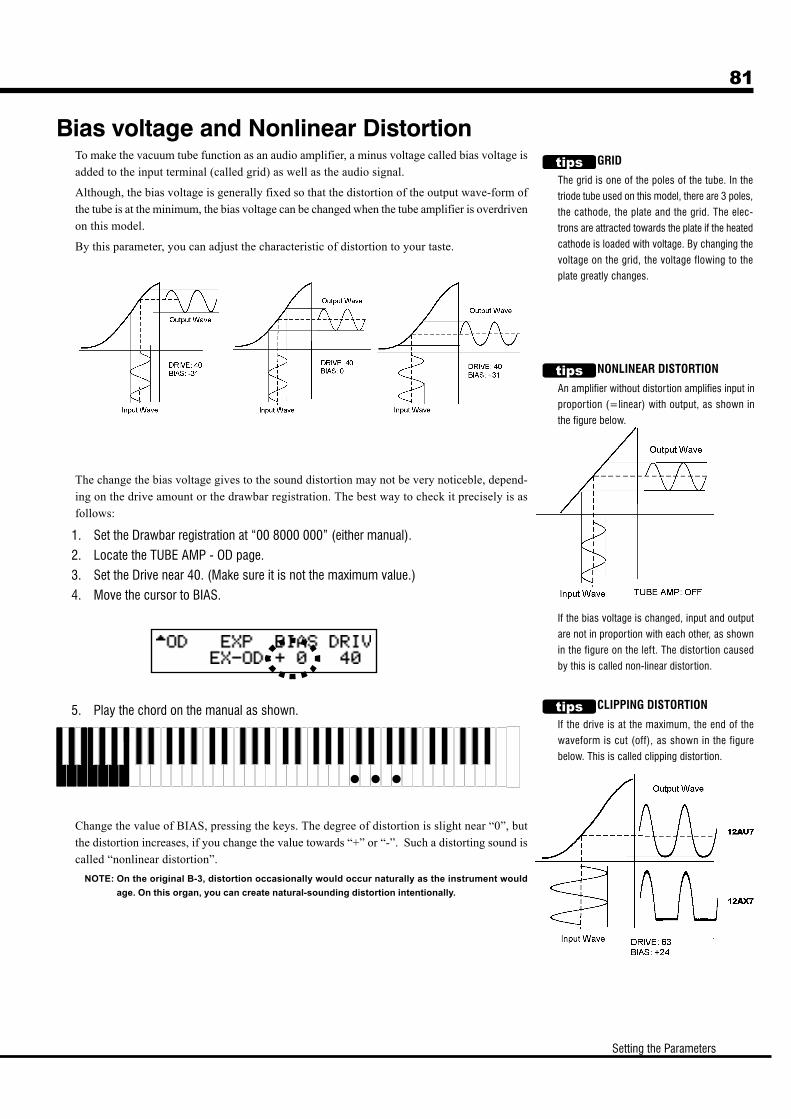
81
Setting the Parameters
GRID
The grid is one of the poles of the tube. In the
triode tube used on this model, there are 3 poles,
the cathode, the plate and the grid. The elec-
trons are attracted towards the plate if the heated
cathode is loaded with voltage. By changing the
voltage on the grid, the voltage flowing to the
plate greatly changes.
NONLINEAR DISTORTION
An amplifier without distortion amplifies input in
proportion (=linear) with output, as shown in
the figure below.
If the bias voltage is changed, input and output
are not in proportion with each other, as shown
in the figure on the left. The distor tion caused
by this is called non-linear distortion.
CLIPPING DISTORTION
If the drive is at the maximum, the end of the
waveform is cut (off), as shown in the figure
below. This is called clipping distor tion.
Bias voltage and Nonlinear DistortionTo make the vacuum tube function as an audio amplifier, a minus voltage called bias voltage is
added to the input terminal (called grid) as well as the audio signal.
Although, the bias voltage is generally fixed so that the distortion of the output wave-form of
the tube is at the minimum, the bias voltage can be changed when the tube amplifier is overdriven
on this model.
By this parameter, you can adjust the characteristic of distortion to your taste.
The change the bias voltage gives to the sound distortion may not be very noticeble, depend-
ing on the drive amount or the drawbar registration. The best way to check it precisely is as
follows:
1. Set the Drawbar registration at “00 8000 000” (either manual).
2. Locate the TUBE AMP - OD page.
3. Set the Drive near 40. (Make sure it is not the maximum value.)
4. Move the cursor to BIAS.
5. Play the chord on the manual as shown.
Change the value of BIAS, pressing the keys. The degree of distortion is slight near “0”, but
the distortion increases, if you change the value towards “+” or “-”. Such a distorting sound is
called “nonlinear distortion”.
NOTE: On the original B-3, distortion occasionally would occur naturally as the instrument would
age. On this organ, you can create natural-sounding distortion intentionally.
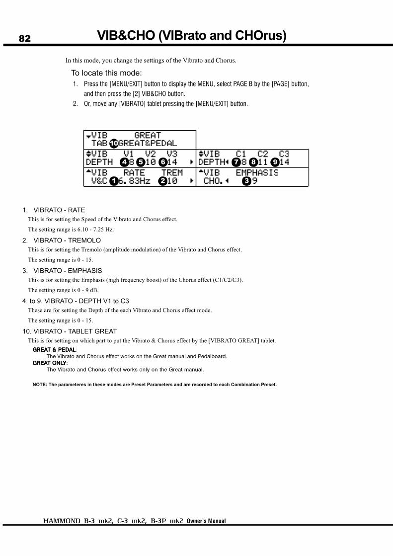
82
Owner’s Manual
VIB&CHO (VIBrato and CHOrus)
1. VIBRATO - RATEThis is for setting the Speed of the Vibrato and Chorus effect.
The setting range is 6.10 - 7.25 Hz.
2. VIBRATO - TREMOLOThis is for setting the Tremolo (amplitude modulation) of the Vibrato and Chorus effect.
The setting range is 0 - 15.
3. VIBRATO - EMPHASISThis is for setting the Emphasis (high frequency boost) of the Chorus effect (C1/C2/C3).
The setting range is 0 - 9 dB.
4. to 9. VIBRATO - DEPTH V1 to C3These are for setting the Depth of the each Vibrato and Chorus effect mode.
The setting range is 0 - 15.
10. VIBRATO - TABLET GREATThis is for setting on which part to put the Vibrato & Chorus effect by the [VIBRATO GREAT] tablet.
GREAGREAGREAGREAGREAT & PEDT & PEDT & PEDT & PEDT & PEDALALALALAL:The Vibrato and Chorus effect works on the Great manual and Pedalboard.
GREAGREAGREAGREAGREAT ONLT ONLT ONLT ONLT ONLYYYYY:The Vibrato and Chorus effect works only on the Great manual.
NOTE: The parameteres in these modes are Preset Parameters and are recorded to each Combination Preset.
In this mode, you change the settings of the Vibrato and Chorus.
To locate this mode:1. Press the [MENU/EXIT] button to display the MENU, select PAGE B by the [PAGE] button,
and then press the [2] VIB&CHO button.
2. Or, move any [VIBRATO] tablet pressing the [MENU/EXIT] button.
1 2 3
4 5 6 7 8 9
10
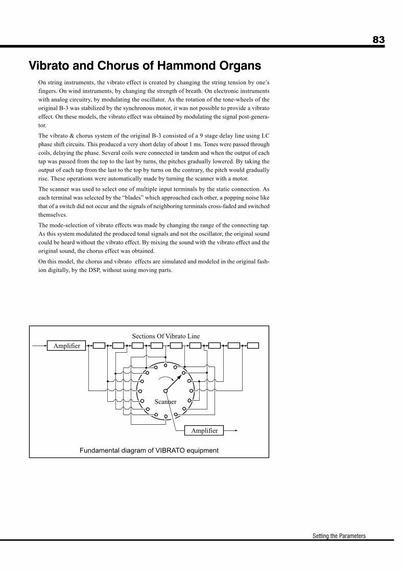
83
Setting the Parameters
On string instruments, the vibrato effect is created by changing the string tension by one’s
fingers. On wind instruments, by changing the strength of breath. On electronic instruments
with analog circuitry, by modulating the oscillator. As the rotation of the tone-wheels of the
original B-3 was stabilized by the synchronous motor, it was not possible to provide a vibrato
effect. On these models, the vibrato effect was obtained by modulating the signal post-genera-
tor.
The vibrato & chorus system of the original B-3 consisted of a 9 stage delay line using LC
phase shift circuits. This produced a very short delay of about 1 ms. Tones were passed through
coils, delaying the phase. Several coils were connected in tandem and when the output of each
tap was passed from the top to the last by turns, the pitches gradually lowered. By taking the
output of each tap from the last to the top by turns on the contrary, the pitch would gradually
rise. These operations were automatically made by turning the scanner with a motor.
The scanner was used to select one of multiple input terminals by the static connection. As
each terminal was selected by the “blades” which approached each other, a popping noise like
that of a switch did not occur and the signals of neighboring terminals cross-faded and switched
themselves.
The mode-selection of vibrato effects was made by changing the range of the connecting tap.
As this system modulated the produced tonal signals and not the oscillator, the original sound
could be heard without the vibrato effect. By mixing the sound with the vibrato effect and the
original sound, the chorus effect was obtained.
On this model, the chorus and vibrato effects are simulated and modeled in the original fash-
ion digitally, by the DSP, without using moving parts.
Vibrato and Chorus of Hammond Organs
Fundamental diagram of VIBRATO equipment

84
Owner’s Manual
LESLIE
CONCEPT OF THE CABINET NUMBERSEach Cabinet represents one vir tual Leslie Speaker pre-
pared by the Leslie Parameter.
This parameter is the only Preset Parameter in this
mode.
CABINET NUMBERS1. CABINET NUMBER
Here you select the CABINET NUMBER to use in the Combination Presets.
The setting range is 1 - 8. The “*” will be displayed when the Leslie Parameters are
changed from this Cabinet Number.
LESLIE PARAMETERS2. CABINET NAME
This is for assigning the Cabinet Names.
Move the cursor by the [PARAM] button and select letters by the [VALUE] button.
In this mode, only the present value “Temporary” changes and there is no determining
operation. You must record the name by doing “Recording the Cabinet” as explained in
the next paragraph. Otherwise the data will be lost.
3. AMPLIFIERThis sets the type of the virtual power amplifier.
SolidSolidSolidSolidSolid: Simulated Solid-State Amplifier with a flat characteristicTTTTTubeubeubeubeube: Simulated Tube Amplifier with a warm characteristic.
In this mode, you make the settings for the built-in Leslie Effect.
There are many parameters for the built-in Leslie Effect. These
individual settings are not recalled by the Combination Presets,
or by bank settings. The built-in Leslie parameters are grouped
in macro-settings called “CABINETS”. You select the CABI-
NET NUMBER in the Combination Presets where this selection
is saved as part of the Preset.
To locate this mode:1. Press the [MENU/EXIT] button to display the MENU. Then
select PAGE B by the [PAGE] button and press [3] LESLIE.
2. Or, move Leslie Speed Switch pressing the [MENU/EXIT] but-
ton.
1
2
3
4
5 6 7 8 9 10 11
12 13 14 15 16 17
18 19
20
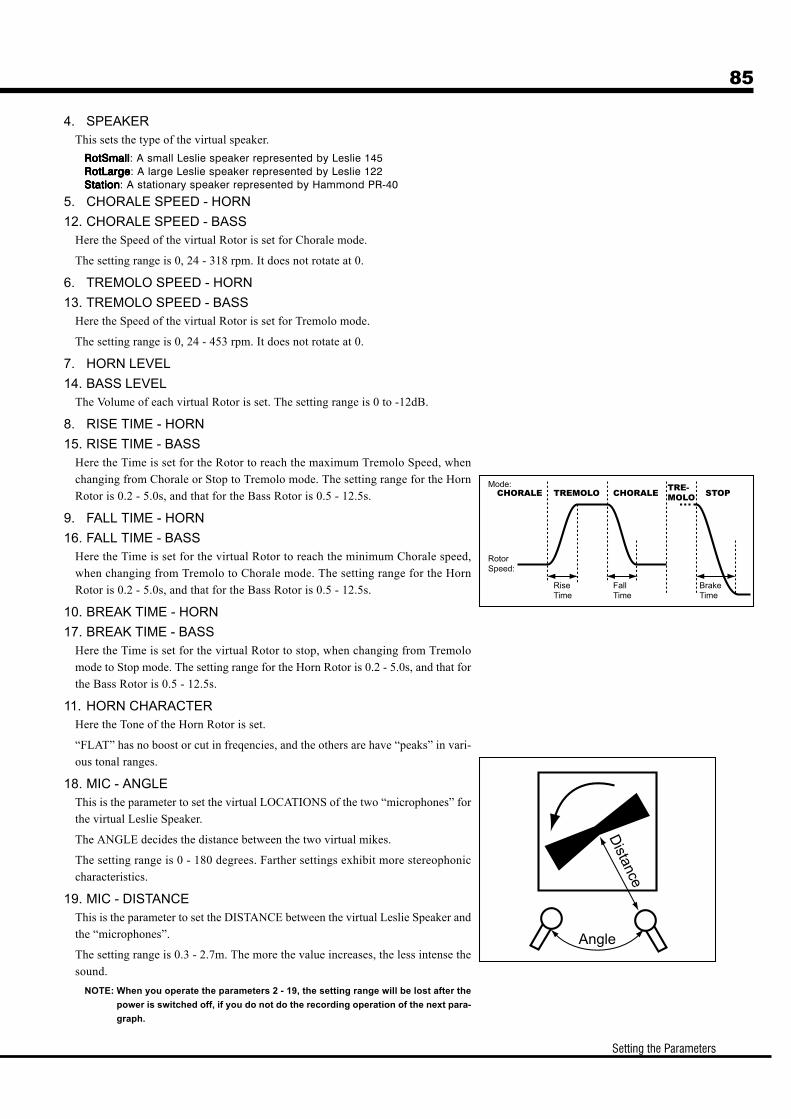
85
Setting the Parameters
4. SPEAKERThis sets the type of the virtual speaker.
RotSmallRotSmallRotSmallRotSmallRotSmall: A small Leslie speaker represented by Leslie 145RotLargeRotLargeRotLargeRotLargeRotLarge: A large Leslie speaker represented by Leslie 122StationStationStationStationStation: A stationary speaker represented by Hammond PR-40
5. CHORALE SPEED - HORN
12. CHORALE SPEED - BASSHere the Speed of the virtual Rotor is set for Chorale mode.
The setting range is 0, 24 - 318 rpm. It does not rotate at 0.
6. TREMOLO SPEED - HORN
13. TREMOLO SPEED - BASSHere the Speed of the virtual Rotor is set for Tremolo mode.
The setting range is 0, 24 - 453 rpm. It does not rotate at 0.
7. HORN LEVEL
14. BASS LEVELThe Volume of each virtual Rotor is set. The setting range is 0 to -12dB.
8. RISE TIME - HORN
15. RISE TIME - BASSHere the Time is set for the Rotor to reach the maximum Tremolo Speed, when
changing from Chorale or Stop to Tremolo mode. The setting range for the Horn
Rotor is 0.2 - 5.0s, and that for the Bass Rotor is 0.5 - 12.5s.
9. FALL TIME - HORN
16. FALL TIME - BASSHere the Time is set for the virtual Rotor to reach the minimum Chorale speed,
when changing from Tremolo to Chorale mode. The setting range for the Horn
Rotor is 0.2 - 5.0s, and that for the Bass Rotor is 0.5 - 12.5s.
10. BREAK TIME - HORN
17. BREAK TIME - BASSHere the Time is set for the virtual Rotor to stop, when changing from Tremolo
mode to Stop mode. The setting range for the Horn Rotor is 0.2 - 5.0s, and that for
the Bass Rotor is 0.5 - 12.5s.
11. HORN CHARACTERHere the Tone of the Horn Rotor is set.
“FLAT” has no boost or cut in freqencies, and the others are have “peaks” in vari-
ous tonal ranges.
18. MIC - ANGLEThis is the parameter to set the virtual LOCATIONS of the two “microphones” for
the virtual Leslie Speaker.
The ANGLE decides the distance between the two virtual mikes.
The setting range is 0 - 180 degrees. Farther settings exhibit more stereophonic
characteristics.
19. MIC - DISTANCEThis is the parameter to set the DISTANCE between the virtual Leslie Speaker and
the “microphones”.
The setting range is 0.3 - 2.7m. The more the value increases, the less intense the
sound.
NOTE: When you operate the parameters 2 - 19, the setting range will be lost after the
power is switched off, if you do not do the recording operation of the next para-
graph.

86
Owner’s Manual
20. STOP MODEThis sets the mode when the Leslie Speed Switch is at “STOP”.
STOPSTOPSTOPSTOPSTOP:The virtual rotors stop.
THROUGHTHROUGHTHROUGHTHROUGHTHROUGH:The Leslie Effect is bypassed. (Through)
NOTE: This parameter is a Preset Parameter. It is recorded to each Combination Preset.

87
Setting the Parameters
The Leslie parameters (2 - 20 of the previous paragraph) can be
recorded with the Cabinet Numbers, enabling their choice in each
Combination Preset.
Record the Cabinets
Enter the desired name for the Cabinet.
Press the [RECORD] button in the setting mode of the Leslie Pa-
rameter.
The Cabinet Selection mode is displayed.
Select the Cabinet Number to record by the [PAGE] button.
Press [4] OK, and the Cabinet’s parameters are recorded.
The display during the recording the recording operation shows as
illustrated.
NOTE: If you wish to cancel the recording, press the [MENU/EXIT] but-
ton.
1
2
3
4
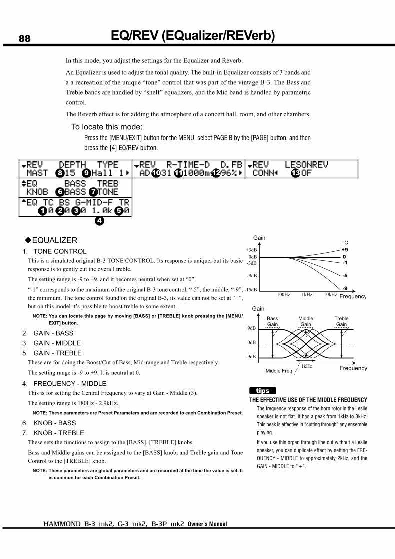
88
Owner’s Manual
In this mode, you adjust the settings for the Equalizer and Reverb.
An Equalizer is used to adjust the tonal quality. The built-in Equalizer consists of 3 bands and
a a recreation of the unique “tone” control that was part of the vintage B-3. The Bass and
Treble bands are handled by “shelf” equalizers, and the Mid band is handled by parametric
control.
The Reverb effect is for adding the atmosphere of a concert hall, room, and other chambers.
To locate this mode:Press the [MENU/EXIT] button for the MENU, select PAGE B by the [PAGE] button, and then
press the [4] EQ/REV button.
EQUALIZER1. TONE CONTROL
This is a simulated original B-3 TONE CONTROL. Its response is unique, but its basic
response is to gently cut the overall treble.
The setting range is -9 to +9, and it becomes neutral when set at “0”.
“-1” corresponds to the maximum of the original B-3 tone control, “-5”, the middle, “-9”,
the minimum. The tone control found on the original B-3, its value can not be set at “+”,
but on this model it’s possible to boost treble to some extent.
NOTE: You can locate this page by moving [BASS] or [TREBLE] knob pressing the [MENU/
EXIT] button.
2. GAIN - BASS
3. GAIN - MIDDLE
5. GAIN - TREBLEThese are for doing the Boost/Cut of Bass, Mid-range and Treble respectively.
The setting range is -9 to +9. It is neutral at 0.
4. FREQUENCY - MIDDLEThis is for setting the Central Frequency to vary at Gain - Middle (3).
The setting range is 180Hz - 2.9kHz.
NOTE: These parameters are Preset Parameters and are recorded to each Combination Preset.
6. KNOB - BASS
7. KNOB - TREBLEThese sets the functions to assign to the [BASS], [TREBLE] knobs.
Bass and Middle gains can be assigned to the [BASS] knob, and Treble gain and Tone
Control to the [TREBLE] knob.
NOTE: These parameters are global parameters and are recorded at the time the value is set. It
is common for each Combination Preset.
THE EFFECTIVE USE OF THE MIDDLE FREQUENCYThe frequency response of the horn rotor in the Leslie
speaker is not flat. It has a peak from 1kHz to 3kHz.
This peak is effective in “cutting through” any ensemble
playing.
If you use this organ through line out without a Leslie
speaker, you can duplicate effect by setting the FRE-
QUENCY - MIDDLE to approximately 2kHz, and the
GAIN - MIDDLE to “+”.
EQ/REV (EQualizer/REVerb)
1 2 34
5
6 7
8 9 10 11 12 13
89
Setting the Parameters
PRESET PARAMETERS
Equalizer and Reverb are Preset Parameters, de-
signed to be actively used as one of the tone-mak-
ing parameters.
If you are using the EQ and Reverb to compensate
for the space you are performing in, It is advisable
to switch off the P.LOAD EQ/RV in the Preset func-
tion mode so, the Equalizer and the Reverb value
will not change when a preset is recalled. (P. 77
#11)
REVERB8. REVERB - DEPTH
This sets the Depth of the Reverb Effect.
The setting range is 0 - 15. As you increase the value, it will give the effect of performing in a
larger room.
NOTE: You can locate this page by moving [REVERB] knob pressing the [MENU/EXIT] button.
9. REVERB - TYPEThis sets the Types of Reverb Effect.
Room 1Room 1Room 1Room 1Room 1: Small roomRoom 2Room 2Room 2Room 2Room 2: Large roomLiveLiveLiveLiveLive: Ambient roomHall 1Hall 1Hall 1Hall 1Hall 1: Large HallHall 2Hall 2Hall 2Hall 2Hall 2: Small HallChurchChurchChurchChurchChurch: ChurchPlatePlatePlatePlatePlate: Iron-plate ReverbSpringSpringSpringSpringSpring: Spring ReverbDelayDelayDelayDelayDelay: DelayPPPPPanDlyanDlyanDlyanDlyanDly: Panning DelayRevDlyRevDlyRevDlyRevDlyRevDly: Reverb + Delay
10. REVERB - TIMEWhen the Type (9) is set at Room 1 to Spring or RevDly, it sets the Time for Reverb to decay.
The setting range is 0 - 31. The higher the value, the longer the decay.
11. REVERB - DELAY TIMEWhen the Type (9) is set at Delay, PanDly, RevDly, this sets the delay time.
The setting range is 4.7 - 2000 ms. The higher the number, the longer the delay.
NOTE: You can set the delay time with the foot switch (P. 91 #4).
12. REVERB - DELAY FEEDBACKWhen the Type (9) is at Delay, PanDly, RevDly, it sets the amount of Feedback. (How many
times the sound repeats.)
The setting range is 0 - 96%. The higher the value, the more repeats.
13. LESLIE ON REVERBThis sets the routing of the Reverb and Leslie Effect.
OFOFOFOFOF: Leslie before ReverbONONONONON: Reverb before Leslie
NOTE: These parameters are Preset Parameters and are recorded to each Combination Preset.

90
Owner’s Manual
MANBS (MANual BaSs)
This mode is for setting the highest note to that will play using the Manual Bass function.
To locate this mode:Press the [MENU/EXIT] button for the MENU, select PAGE C by the [PAGE] button, and then
press the [2] MANBS button.
1. MANUAL BASS - LIMITSets the highest note of the Manual Bass functions on the Great manual.
NOTE: In this parameter, you can set the value by pressing the [RECORD] button, while holding
down a note on the Great manual.
1

91
Setting the Parameters
CONTROL
This mode is for setting the Motor Control Switch, Foot Switch and Expression Pedal.
To locate this mode:Press the [MENU/EXIT] button and display the MENU and select PAGE C by the [PAGE]
button, and then press the [3] CONTROL button.
MOTOR CONTROL SWITCH1. MOTOR - DOWN (G)
2. MOTOR - UP (G)This is for setting the time required for the pitch change, when you
operate the [MOTOR CONTROL] Switch.
The setting range is 0.1 - 9.9 seconds.
NOTE: You can locate this page by moving Motor Control switch press-
ing the [MENU/EXIT] button.
3. MOTOR - AMP (G)This is for setting the motion of the amp when you push the [MO-
TOR CONTROL] switch to “DOWN”.
If you switch ON, the pitch and volume drop together.
FOOT SWITCH4. FOOT SWITCH - FUNCTION (G)
This is for setting the function of the Foot Switch.
OFFOFFOFFOFFOFF: Foot Switch is disabled.LESLIE C/T ALLESLIE C/T ALLESLIE C/T ALLESLIE C/T ALLESLIE C/T ALTTTTT, MOM, MOM, MOM, MOM, MOM:
These are for switching Chorale/Tremolo of the Leslie Ef-fect. At ALT, Chorale/Tremolo is alternately switched ateach press of the Foot Switch, and switches to Stop ifpressed for longer than 1 second. At MOM, the Leslie effectswitches to Tremolo, as long as the foot switch is de-pressed, and switches to Chorale when you release it.
SPRINGSPRINGSPRINGSPRINGSPRING:This is for producing the effect of shaking a spring reverb.
DELADELADELADELADELAY TIMEY TIMEY TIMEY TIMEY TIME:This function sets the delay time (P. 89 #11) of the reverbeffect(if the “delay” setting is selected), by rhythmic tap-ping the foot-switch. The delay time will be set to the tempoat which you tap the foot switch. By pressing and holdingthe foot-switch, the delay sound will be erased.
REVERB DEPTH:REVERB DEPTH:REVERB DEPTH:REVERB DEPTH:REVERB DEPTH:Changes the Reverb Depth to MAXIMUM while pressingthe Foot Switch regardless of the Reverb parameter set-ting.
NOTE: You can locate this page by pushing Foot switch while pressing
the [MENU/EXIT] button.
EXPRESSION PEDAL5. EXPRESSION - MINIMUM LEVEL (G)
Sets the minimum level when the Expression pedal at its “back”
position. The setting range is OFF, -40db to 0db. “OFF” renders
the organ silent, when the Expression is at minimum, “0dB” pro-
duces no reduction in volume.
6. EXPRESSION - LIMIT LF (G)
7. EXPRESSION - LIMIT HF (G)These are for setting the levels to maintain for low and high fre-
quencies when the Expression is minimum.
The setting range is OFF, -40dB to -5dB. This function does not
work at “OFF”. Otherwise the level is maintained even if the Ex-
pression is minimum.
8. EXPRESSION - CURVE (S)This is for setting how the value varies corresponding to the de-
pressing angle of the Expression Pedal. 1 - 3 are curves for playing
while sitting on the bench, 4 - 5 are those for the playing while
standing. See the bottom right figure for details.
9. EXPRESSION - MONITORDisplays the present Expression Value.
NOTE: The parameters by the names with (G) on the tail are for “Glo-
bal”. These parameters will be recorded when set, and are com-
mon in each Combination Preset. (S) is for “System”. These
parameters will be recorded when set, and are common in each
Combination Preset, and it does not save to setup.
Degree
Value
1 2 3
4
5 6 7 8

92
Owner’s Manual
CUST. TW (CUSTom Tone-Wheels)
In this mode, you can regulate the tonal qualities of the virtual
tone-wheel generator, wheel by wheel.
The virtual tone-wheel generator consists of 96 different pitches,
where one wheel may correspond with plural notes and the “foot”
designation of the Drawbars.
The relation is complicated. For example, the middle C of 8' and
the C one octave lower of 4' use the identical wheel.
In this organ, you can save 2 types of settings per virtual Tone-
INITIAL VALUE OF THE CUSTOM NUMBERAs the initial value, the typical setting is recorded to
each Custom No. 1.
For example, “Real B-3”, a simulated original B-3 in
good condition, is in B-Type 1.
1. TONE-WHEEL SETThis is for selecting the Tone-Wheel set.
2. CUSTOM NUMBERThis is for selecting the “CUSTOM NUMBER” to use or compile. The “*” will be dis-
played when the Tone-wheel parameters are changed from this Custom Number.
NOTE: This parameter is a Global Parameter. It is not recorded into the Combination Preset.
3. CUSTOM NAMEYou can name the CUSTOM TONEWHEELS using up to 10 letters.
Move the cursor by the [PARAM] button and choose the letters by the [VALUE] button.
By pressing the [VALUE] button while holding down the [RECORD] button, it jumps to
the top of each letter type (space, 0, A, a).
The name set here, as well as the Tonewheel parameters below, will be deleted, if you do
not do the recording operation as explained on the next paragraph.
4. WHEEL NUMBERSelect the number of the wheel you want to adjust.
To select the Wheel Number, select the [VALUE] button, or slightly move the feet of the
Drawbar while depressing the key you want to regulate. (See the illustration.)
When the Wheel Number is selected, the level for the wheel (#5) is displayed.
Wheel Set. These are called “CUSTOM TONE-WHEELS”.
The factory default gives a choice of B-3 “types”. You may cre-
ate your own.
To locate this mode:Press the [MENU/EXIT] button and display MENU, select PAGE
C by the [PAGE] button, and then press the [4] CUST. TW
button.
How to select the WHEEL NUMBER
1
2
3
54
4 6 7
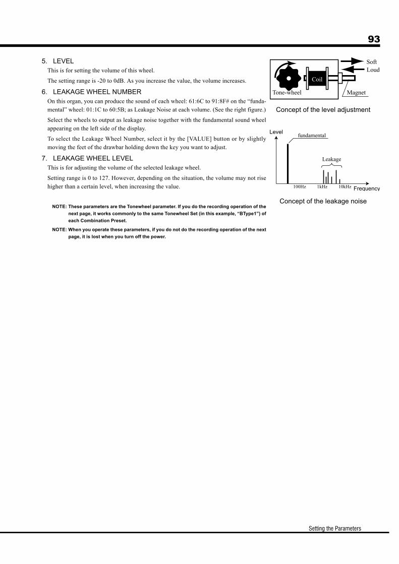
93
Setting the Parameters
5. LEVELThis is for setting the volume of this wheel.
The setting range is -20 to 0dB. As you increase the value, the volume increases.
6. LEAKAGE WHEEL NUMBEROn this organ, you can produce the sound of each wheel: 61:6C to 91:8F# on the “funda-
mental” wheel: 01:1C to 60:5B; as Leakage Noise at each volume. (See the right figure.)
Select the wheels to output as leakage noise together with the fundamental sound wheel
appearing on the left side of the display.
To select the Leakage Wheel Number, select it by the [VALUE] button or by slightly
moving the feet of the drawbar holding down the key you want to adjust.
7. LEAKAGE WHEEL LEVELThis is for adjusting the volume of the selected leakage wheel.
Setting range is 0 to 127. However, depending on the situation, the volume may not rise
higher than a certain level, when increasing the value.
NOTE: These parameters are the Tonewheel parameter. If you do the recording operation of the
next page, it works commonly to the same Tonewheel Set (in this example, “BType1”) of
each Combination Preset.
NOTE: When you operate these parameters, if you do not do the recording operation of the next
page, it is lost when you turn off the power.
Concept of the level adjustment
Concept of the leakage noise
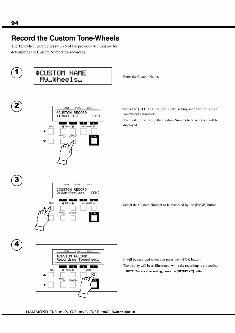
94
Owner’s Manual
1
2
3
4
Record the Custom Tone-WheelsThe Tonewheel parameters (= 3 - 5 of the previous Section) are for
determining the Custom Number for recording.
Enter the Custom Name.
Press the [RECORD] button in the setting mode of the virtual
Tonewheel parameters.
The mode for selecting the Custom Number to be recorded will be
displayed.
Select the Custom Number to be recorded by the [PAGE] button.
It will be recorded when you press the [4] OK button.
The display will be as illustrated, while the recording is proceeded.
NOTE: To cancel recording, press the [MENU/EXIT] button.
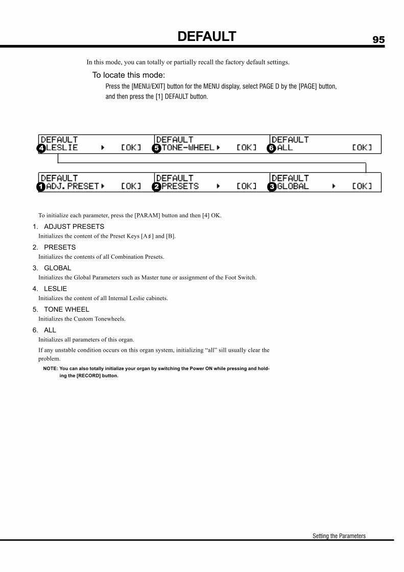
95
Setting the Parameters
DEFAULT
In this mode, you can totally or partially recall the factory default settings.
To locate this mode:Press the [MENU/EXIT] button for the MENU display, select PAGE D by the [PAGE] button,
and then press the [1] DEFAULT button.
To initialize each parameter, press the [PARAM] button and then [4] OK.
1. ADJUST PRESETSInitializes the content of the Preset Keys [A<] and [B].
2. PRESETSInitializes the contents of all Combination Presets.
3. GLOBALInitializes the Global Parameters such as Master tune or assignment of the Foot Switch.
4. LESLIEInitializes the content of all Internal Leslie cabinets.
5. TONE WHEELInitializes the Custom Tonewheels.
6. ALLInitializes all parameters of this organ.
If any unstable condition occurs on this organ system, initializing “all” sill usually clear the
problem.
NOTE: You can also totally initialize your organ by switching the Power ON while pressing and hold-
ing the [RECORD] button.
1 2 3
4 5 6
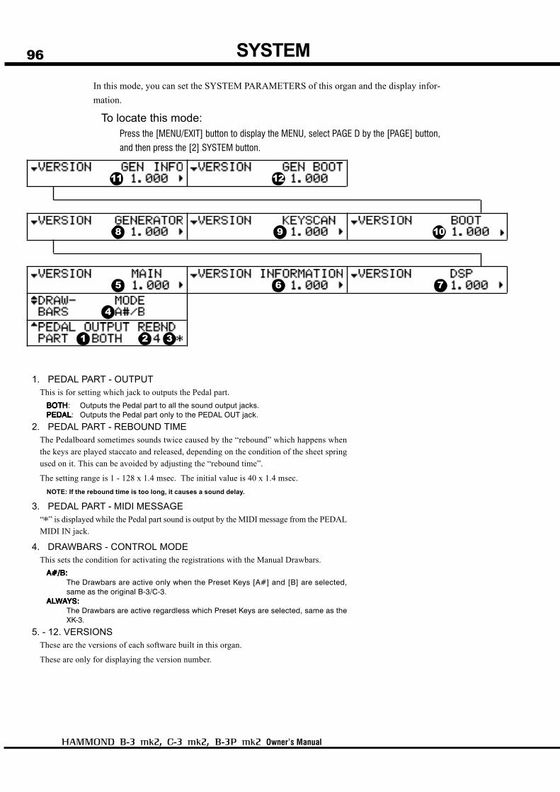
96
Owner’s Manual
SYSTEM
1. PEDAL PART - OUTPUTThis is for setting which jack to outputs the Pedal part.
BBBBBOTHOTHOTHOTHOTH: Outputs the Pedal part to all the sound output jacks.PEDPEDPEDPEDPEDALALALALAL: Outputs the Pedal part only to the PEDAL OUT jack.
2. PEDAL PART - REBOUND TIMEThe Pedalboard sometimes sounds twice caused by the “rebound” which happens when
the keys are played staccato and released, depending on the condition of the sheet spring
used on it. This can be avoided by adjusting the “rebound time”.
The setting range is 1 - 128 x 1.4 msec. The initial value is 40 x 1.4 msec.
NOTE: If the rebound time is too long, it causes a sound delay.
3. PEDAL PART - MIDI MESSAGE“*” is displayed while the Pedal part sound is output by the MIDI message from the PEDAL
MIDI IN jack.
4. DRAWBARS - CONTROL MODEThis sets the condition for activating the registrations with the Manual Drawbars.
A#/B:A#/B:A#/B:A#/B:A#/B:The Drawbars are active only when the Preset Keys [A#] and [B] are selected,same as the original B-3/C-3.
ALALALALALWWWWWAAAAAYS:YS:YS:YS:YS:The Drawbars are active regardless which Preset Keys are selected, same as theXK-3.
5. - 12. VERSIONSThese are the versions of each software built in this organ.
These are only for displaying the version number.
In this mode, you can set the SYSTEM PARAMETERS of this organ and the display infor-
mation.
To locate this mode:Press the [MENU/EXIT] button to display the MENU, select PAGE D by the [PAGE] button,
and then press the [2] SYSTEM button.
1 2 3
5 6 7
8 9 10
11 12
4

97
Owner’s Manual
MIDI

98
Owner’s Manual
ABOUT MIDI
MIDI OUT
Sends Performance Information.
MIDI PEDAL IN
Receives the performance information of the Pedal part.
Receives only the note message and the setting is fixed at OMNI ON.
On this organ, the MIDI terminals are intended to do the following:
control an external sound generator such as a synthesizer or sampler.
use a MIDI Pedal board instead of the traditional Pedalboard.
Due to the exclusive electro-mechanical “Direct Analog Keying System”, it
is impossible to “play” this organ from a remote MIDI source, such as a
sequencer or MIDI controller.
What is “MIDI”?MIDI is an abbreviation of Musical Instrument Digital Interface.
MIDI is the musical instrument industry standard for exchanging performance information
between electronic musical instruments and a sequencer, effects, lighting, and sound
reiinforcement gear, etc.
The MIDI standard allows instruments made by different manufacturers to effectively commu-
nicate with each other.
Many types of data can be transmitted and received, including all performance information,
settings of parameters, and global commands.
MIDI terminals on this Organ
What the MIDI can do on your Organ

99
MIDI
MIDI CHANNELMIDI has 16 “CHANNELS”. Information divided into 16 channels can transmit through one
MIDI cable.
The channel must match between the sender and the receiver. If not, the machines can not
“hear” what the other “says”.
MAJOR MIDI MESSAGEThe MIDI infomation is grouped into a channel message per each of the 16 channels and a
system message for all channels. There are more details in the MIDI IMPLEMENTATION
CHART.
CHANNEL MESSAGENOTE ON / NOTE OFF
This data tells: which key (Note Number) is played, at what Speed (Velocity) and whether
played or released (Note On/Off).
The MIDI PEDAL IN jack on this organ receives only Note On/Note Off.
It does not recognize velocity commands.
PROGRAM CHANGESwitches the programs of External MIDI equipment.
CONTROL CHANGEData will be sent corresponding to the action of the Expression Pedal, Foot Switch, etc.
SYSTEM MESSAGESYSTEM EXCLUSIVE MESSAGE
This organ does not send/receive the system exclusive message.

100
Owner’s Manual
This organ has 3 “External Zones” on each of the Swell, Great and Pedalboards for
controlling the external MIDI equipment.
MIDI STRUCTURE
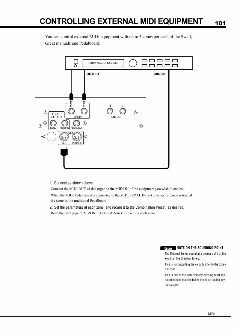
101
MIDI
1. Connect as shown above.Connect the MIDI OUT of this organ to the MIDI IN of the equipment you wish to control.
When the MIDI Pedal board is connected to the MIDI PEDAL IN jack, the performance is treated
the same as the traditional Pedalboard.
2. Set the parameters of each zone, and record it to the Combination Preset, as desired.Read the next page “EX. ZONE (External Zone)” for setting each zone.
You can control external MIDI equipment with up to 3 zones per each of the Swell,
Great manuals and Pedalboard.
NOTE ON THE SOUNDING POINT
The External Zones sound at a deeper point of the
key than the Drawbar tones.
This is for outputting the velocity info. to the Exter-
nal Zone.
This is due to the extra velocity-sensing MIDI key-
board contact that lies below the direct analog key-
ing system.
CONTROLLING EXTERNAL MIDI EQUIPMENT
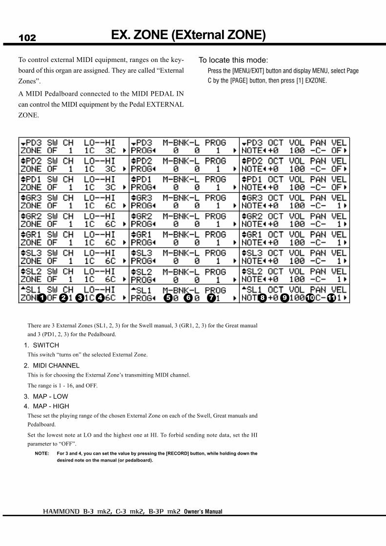
102
Owner’s Manual
EX. ZONE (EXternal ZONE)
There are 3 External Zones (SL1, 2, 3) for the Swell manual, 3 (GR1, 2, 3) for the Great manual
and 3 (PD1, 2, 3) for the Pedalboard.
1. SWITCH
This switch “turns on” the selected External Zone.
2. MIDI CHANNEL
This is for choosing the External Zone’s transmitting MIDI channel.
The range is 1 - 16, and OFF.
3. MAP - LOW
4. MAP - HIGH
These set the playing range of the chosen External Zone on each of the Swell, Great manuals and
Pedalboard.
Set the lowest note at LO and the highest one at HI. To forbid sending note data, set the HI
parameter to “OFF”.
NOTE: For 3 and 4, you can set the value by pressing the [RECORD] button, while holding down the
desired note on the manual (or pedalboard).
To control external MIDI equipment, ranges on the key-
board of this organ are assigned. They are called “External
Zones”.
A MIDI Pedalboard connected to the MIDI PEDAL IN
can control the MIDI equipment by the Pedal EXTERNAL
ZONE.
To locate this mode:Press the [MENU/EXIT] button and display MENU, select Page
C by the [PAGE] button, then press [1] EXZONE.
1 2 3 4 5 6 7 8 9 10 11
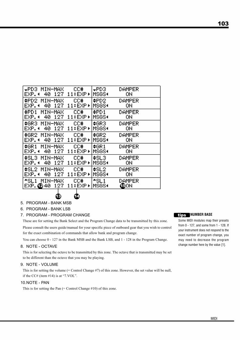
103
MIDI
5. PROGRAM - BANK MSB
6. PROGRAM - BANK LSB
7. PROGRAM - PROGRAM CHANGE
These are for setting the Bank Select and the Program Change data to be transmitted by this zone.
Please consult the users guide/manual for your specific piece of outboard gear that you wish to control
for the exact combination of commands that allow bank and program change.
You can choose 0 - 127 in the Bank MSB and the Bank LSB, and 1 - 128 in the Program Change.
8. NOTE - OCTAVE
This is for selecting the octave to be transmitted by this zone. The octave that is transmitted may be set
to be different than the octave that you may be playing.
9. NOTE - VOLUME
This is for setting the volume (= Control Change #7) of this zone. However, the set value will be null,
if the CC# (item #14) is at “7.VOL”.
10.NOTE - PAN
This is for setting the Pan (= Control Change #10) of this zone.
NUMBER BASE
Some MIDI modules map their presets
from 0 - 127, and some from 1 - 128. If
your instrument does not respond to the
exact number of program change, you
may need to decrease the program
change number here by the value [1].
12
13 14
15
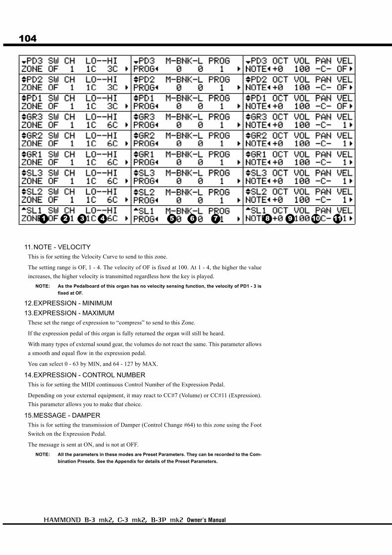
104
Owner’s Manual
11.NOTE - VELOCITY
This is for setting the Velocity Curve to send to this zone.
The setting range is OF, 1 - 4. The velocity of OF is fixed at 100. At 1 - 4, the higher the value
increases, the higher velocity is transmitted regardless how the key is played.
NOTE: As the Pedalboard of this organ has no velocity sensing function, the velocity of PD1 - 3 is
fixed at OF.
12.EXPRESSION - MINIMUM
13.EXPRESSION - MAXIMUM
These set the range of expression to “compress” to send to this Zone.
If the expression pedal of this organ is fully returned the organ will still be heard.
With many types of external sound gear, the volumes do not react the same. This parameter allows
a smooth and equal flow in the expression pedal.
You can select 0 - 63 by MIN, and 64 - 127 by MAX.
14.EXPRESSION - CONTROL NUMBER
This is for setting the MIDI continuous Control Number of the Expression Pedal.
Depending on your external equipment, it may react to CC#7 (Volume) or CC#11 (Expression).
This parameter allows you to make that choice.
15.MESSAGE - DAMPER
This is for setting the transmission of Damper (Control Change #64) to this zone using the Foot
Switch on the Expression Pedal.
The message is sent at ON, and is not at OFF.
NOTE: All the parameters in these modes are Preset Parameters. They can be recorded to the Com-
bination Presets. See the Appendix for details of the Preset Parameters.
1 2 3 4 5 6 7 8 9 10 11
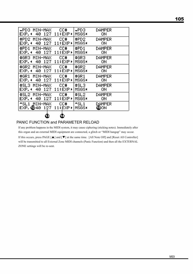
105
MIDI
PANIC FUNCTION and PARAMETER RELOADIf any problem happens in the MIDI system, it may cause ciphering (sticking notes). Immediately after
this organ and an external MIDI equipment are connected, a glitch or “MIDI hangup” may occur.
If this occurs, press PAGE [ ] and [ ] at the same time. [All Note Off] and [Reset All Controller]
will be transmitted to all External Zone MIDI channels (Panic Function) and then all the EXTERNAL
ZONE settings will be re-sent.
12
13 14
15
106
Owner’s Manual
107
Owner’s Manual
SAVE THE SETUP
108
Owner’s Manual
SAVE YOUR SETUP
CF CARD YOU CAN USEThe manufacturer recommends genuine Hammond 65971-02128
as your CF card.
Please consult URL: http://www.hammondsuzuki.com before you
try to use other cards on the market.
CF CARD SLOT1. First please read the label on the CF card carefully and insert
it correctly.
2. To take out the card, push the EJECT button on the right hand
side of the slot.
3. Don’t eject the card or switch the power off during initializing
or setting it up.
How to access the CF card slot
THE CARD CAPACITY AND CONTENT TO BE
SAVEDThe CF card can save:
Combination Presets
Global Parameters
Custom Tonewheels
Leslie Cabinets
Adjust Presets [A<], [B]
Temporary ParametersAlso, this card can save/read out all of them as a whole by the unit
called “SET-UP”. The capacity of one SET-UP is approximately
44 KB.
B-3 mk2, C-3 mk2 B-3P mk2
Turn and remove the knob bolts with a coin from the back of the
organ. Then take off the rear panel.
Turn the screws with the #2 Phillips screw driver and take off the
HAMMOND plate on the back of the organ.
About the CF Card
On this organ you can save the setting of each Parameter as a file, into a
CompactFlash™ card (hereinafter “CF card”) up to 99 files.
Eject Button
109
Save the Setup
INITIALIZE THE CF CARD
The CF CARD must be “INITIALIZED” first (= before you use it). Perform the
following, step by step, to do the initializing operation.
This operation erases all data in the CF card.
Insert the CF card into the slot.
Press the [MENU/EXIT] button.
Select PAGE D by the [PAGE] button.
Press [4] CF FORM.
The FORMAT mode is displayed.
Press the [4] OK button.
The Confirmation message is displayed.
Press the [4] YES button.
The initialization starts and takes only a few seconds.
NOTE: To cancel initializing, press the [3] NO button.
To return to the PLAY mode, press [PLAY].
1
2
3
5
6
7
4
110
Owner’s Manual
SETUP PROCEDURES
Save the SETUP
2
5
Save or Load the SET UP to/from the CF card in the SETUP mode. In this mode, you
can do all the operations except the initialization of the CF card.
To come to this menu:Press the [MENU] button to display the MENU, select PAGE D by the [3] SETUP button.
How to read the Display
This indicates there is another
SETUP file above (or below).
Go to the SETUP mode.
WHAT DOES THIS MEAN?CF is not ready
The CF card is not correctly inserted.
Check that the CF card is correctly inserted.
Select the SET UP NAME “NewSetup” by the [PAGE]
button.
NOTE: “NewSetup” means a fresh save. If you select an
existing SET UP NAME, it will be deleted and writ-
ten over.
Press the [2] SAV button.
SAVE starts.
A temporary name is put to the saved SETUP “Setup xx” auto-
matically.
Setup Name
Load
Save
Rename
Delete
3
1 4
111
Save the Setup
Change the SETUP name
1
2
3
Select the SETUP file you want to change the name of.
Press the [3] NAM button. This is the SETUP NAME IN-
PUT mode.
Input the new SET UP NAME.
[PARAM] BUTTON
Move the cursor.
You can use up to 16 letters.
[VALUE] BUTTON
Choose the letters by this.
You can use Large and small characters, digits and signs/
symbols.
If you press this button, holding down the [RECORD] but-
ton, you can move to the head/the first letter of each type
(= space, 0, A, a).
Move the cursor to the right end by the [PARAM] button.
[ENT] will be displayed.
Press the [4] ENT button.
The SETUP NAME will be changed.
5
4

112
Owner’s Manual
Loading the SETUP How to delete the SETUPAfter the operation, the settings already in
this organ will be replaced by the newly
loaded SETUP.
Check the CF card is correctly inserted.
Navigate to the SETUP mode.
Choose the SETUP file to load by the [PARAM] button.
Press the [1] LOD button.
The SETUP will be loaded in a few seconds.
Check the CF card is correctly inserted.
Navigate to the SETUP mode.
Choose the SETUP file you want to delete by the [PAGE] but-
ton.
Press the [4] DEL button.
The Confirmation message will be displayed.
Press the [4] YES button.
The Delete operation starts.
NOTE: To cancel the delete action, press the [3] NO button.
4
3
2
1
3
2
1
4
5

113
Owner’s Manual
FREQUENTLY ASKEDQUESTIONS

114
Owner’s Manual
UTILIZING NEW FUNCTIONS & FEATURES
How to control the leakage sound:The leakage volume of the whole tone-wheel set currently selected is adjustable by the LEAKAGE Pa-
rameter in the DRAWBAR Function mode. (P. 72 #2)
Adjustment of the leakage interval and or volume per each wheel can be made by using the Custom
Tone-wheel. (P. 92)
How to turn on PEDAL SUSTAIN:Press [PLAY] and display “P.SUS”, then select “ON” by [VALUE]. The length of sustain effects is
controlled by the SL parameter in the DRAWBAR function mode. (P. 73 #8)
How to record other parameters than drawbars to the preset keys:The memory/record operation on this organ also enables you to record various parameters along with the
Drawbar registrations. To set the parameter to call when the preset key is selected, set the parameters on
the P. LOAD page in the PRESET function mode. (P. 76)
How to see the actual values of a preset:In case the physical location of the controller and the actual value do not exactly match when you call a
preset such as the [VIBRATO] tablet, you can display the actual value by operating the controller hold-
ing down the [PLAY] button. (P. 78) The actual Drawbar registration is displayed in PLAY mode.
How to locate each function mode easily?You can “short-cut” to each function mode by moving some controllers (e.g. tablets, knobs) while press-
ing the [MENU/EXIT] button.
How to adjust the Drawbar settings while playing with the Preset C< - A:To temporarily adjust the Drawbar settings while you are playing with the preset keys [C<] - [A], operate
Drawbars holding down the [PLAY] button. (P. 52)
Relation between the built-in Leslie effect and the external Leslie speaker:If no Leslie speaker is connected or headphones are used while a Leslie speaker is connected, the built-
in Leslie effects are added to both (L & R) channels.
If a Leslie speaker is connected, the built-in Leslie effects are added only to the L channel.
How to avoid adding Leslie effects on the Pedal part:The Pedal Part sound is independently output at the PEDAL OUT jack. The built-in Leslie effects,
Reverb, Tube Buffer do not function at this jack.
By connecting the PEDAL OUT jack and the PA equipment and setting the SYSTEM-PEDAL PART
OUTPUT parameter to “PEDAL”, the manual part and the pedal part are separately output to the Leslie
speaker and the PEDAL OUT jack respectively (P. 96 #1).
How to change the motion of the built-in Leslie effect when the Leslie mode
switch is set at “STOP”.The default setting of the built-in Leslie effects on this organ is to bypass (thru) when the Leslie mode
switch is set at “STOP”, so you can enjoy the sound engine’s original sound.
To get the effect of the rotor stop of the Leslie speaker at this time, set the STOP mode at “STOP” in the
LESLIE function mode. (P.86 #20)
How to totally cut off the sound when the expression pedal is returned.The characteristic of the Expression Pedal can be freely changed.
To turn off the sound completely when the Expression Pedal is returned, set all the minimum level, limit
LF, limit HF at “OFF” in the CONTROL function mode. (P. 91 #5, #6, #7)

115
Frequently Asked Questions
Malfunction of the buttons, the keys, etc.Turn off the POWER switch once, then turn it on again. If this procedure is not successful, turn off the
POWER switch. While pressing the [RECORD] button, turn the POWER switch on again. (Note that in this
case, all parameters return to their factory-preset status.)
No sound is produced when the keys are pressed.The MASTER VOLUME is at the minimum setting.
Adjust the volume with the MASTER VOLUME control. (P. 22 #25)
No Preset key is selected.
Select a Preset key.
A plug is inserted to the HEADPHONE jack.
While a plug is inserted here, the Leslie speaker is disabled.
The Foot Switch does not work.The Foot Switch settings are not correct.
Reset the Foot Switch correctly in the CONTROL mode. (P. 91 #4)
The sound does not come out immediately after switched on.A Vacuum Tube circuit is mounted in this organ. It takes approximately 10 to 20 seconds after switched on
before you will hear the sound.
The sound is not distorted if the OVERDRIVE knob is turned.When the Overdrive Expression is at “EX-OD”, it does not distort if the Expression pedal is low. In such a
case, increase the Expression pedal, or set the Overdrive Expression at “OD-EX” if you want to distort
regardless of the Expression value. (P. 80 #1)
Leslie speaker sound is distorted.If the sound is distorted regardless of the position of the volume of the Leslie speaker when you are using a
Leslie adapter (such as the 11 pin/6 pin converter), the power of this organ seems to be so large that the sound
is distorted inside the Leslie adapter. In such a case, return the [MASTER VOLUME] knob to 10 o’clock
position.
The rotor of the external Leslie speaker does not stop, if the Leslie mode is switched
to [STOP].Some Leslie Speaker models do not [STOP]. [STOP] is possible on 2101/2102, 122XB, 971 and 3300 (cur-
rent models).
Audio is interrupted when a Combination Preset is selected.Between the Combination Presets with different Tonewheel Settings, the sound will be cut off while the
Tonewheel Settings are switched.
The sound is once cut between the presets with different key mode (MONO/POLY) on the Pedal part, for
switching the sound algorithm.
There is excessive MIDI latency compared to the organ (Drawbar) sound.The position of the key contact for MIDI send is deeper than that of the multi-contacts for Drawbars.
There are too many zones to send.
Turn [OFF] the switches of unnecessary external zones.
No sounds of Pedal part from the headphones.PEDAL OUTPUT set at “PEDOUT”.
Set the PEDAL OUTPUT at “BOTH” when using the headphones (P. 96 #1).
Manual contact does not work well.The multi-contacts used for the manuals on this organ is designed to be used for a long time. Refer for the
contact refreshing procedures to the “Instruction for keyboard contact cleaning function”.
And, if all the contact points have been worn out and the problem is not solved any longer by refreshing the
contacts, please consult your local dealer or store for further maintenance.
TROUBLESHOOTING

116
Owner’s Manual
DAILY CARE AND MAINTENANCE
How to care for your organ:When you want to clean the keys or cabinets, use only a soft cloth. If they are extremely dirty, use
a barely damp cloth with a neutral detergent. Never apply alcohol, thinner or benzine.
There is no MIDI IN jack for the manual part;Because of electro-mechanical direct analog keying mechanism is adopted on this organ, the
information of each of the multi-contacts is not defined with a MIDI message.
The Leslie Speed Switch cord is too long:A rather long cord is provided for the Leslie Speed Switch, so the player can move the unit as
desired. If it is longer than desired, please bind and fix the extra portion with a wire clamp.
Do I need to oil my organ?There is no part needing oiling on your organ.

117
Owner’s Manual
APPENDIX

118
Owner’s Manual
MIDI IMPLEMENTATION CHART
[Hammond Console Organ] Date: 9-June-2008Model: B-3 mk2 Version: 1.0
Default Off Omni On Tx: External ZonesChanged 1 - 16 ***** Rx: Pedal PartDefault 3 1Messages X XAltered ***** X
12 - 120 36 - 60: True Voice ***** 36 - 60Note ON O XNote OFF X X
After Key's X XTouch Ch's X XPitch Bender X X
0, 32 O X Bank Select MSB, LSB7 O X Volume
10 O X Pan11 O X Expression64 O X Hold 1
121 O X Reset All Controllers
O 0 - 127 X: True # ***** X
System Exclusive X X: Song Position X X: Song Select X X: Tune X X: Clock X X: Commands X X: Local On/Off X X: All Notes Off O O: Active Sense O O: Reset X X
Mode 1: OMNI ON, POLY Mode 2: OMNI ON, MONO O: YesMode 3: OMNI OFF, POLY Mode 4: OMNI OFF, MONO X: No
RemarksBasicChannel
SystemReal Time
AuxMessages
Mode
NoteNumber
Velocity
ControlChange
MIDI Implementation Chart
Function
ProgramChange
SystemCommon
Transmitted Recognized

Appendix
119PARAMETERS
Global ParametersCategory
Parameter Data Range DefaultBank Name (8 Characters) each bank
Transpose -6 - 0 - 6 0
Master Tune 430 - 440 - 450 440
Min. Level Off, -40dB - -0dB -27dB
Min. Limit LF -20dB
Min. Limit HF -30dB
Curve 00 - 04 (1 - 5) 1
FootSwitch
Mode OffLeslie C/T (alternate)Leslie C/T (momentarily)Spring ShockDelay TimeReverb Depth
Leslie C/T (alternate)
Bend Time Down 0.1 - 9.9s 5.0sBend Time Up 0.1 - 9.9s 1.0sBend Amplitude Off / On OnLink Great-Pedal (G-P) Off / On Off
Manual Bass (MANBS) Off / On Off
External Zone Swell (EXT-S) Off / On Off
External Zone Great (EXT-G) Off / On Off
Reverb, Equalizer (RV/EQ) Off / On Off
Leslie, Vibrato (ANI/OD) Off / On Off
Registration Swell (SWELL) Off / On On
Registration Great (GREAT) Off / On On
Drawbar (DRAWB) Off / On Off
Percussion (PERCUS) Off / On Off
Combi.PresetLoad
Global Parameters
Tune
ExpressionOff, -60dB - -0dB
MotorControl

120
Owner’s Manual
Preset ParametersCategory
Parameter Data P. loadManual Bass On Off / On
Manual Bass Range High 1C - 6C
Switch Off / OnChannel 1 - 16, OffBank MSB 0 - 127Bank LSB 0 - 127Program Change 1 - 128Octave Shift -2 - 0 - +2Volume 0 - 127Pan L64 - C - R63Vel. Curve Off, Normal - EasyExp. Min 0 - 63Exp. Max 64 - 127Exp. CC# 7, 11Tx. Damper Off / OnKey Range Low 1C - 5BKey Range High 1C# - 6C, Off
MANBS
EXT(Swell 1 -Swell 3)
EXT andG-P(Great 1 -Pedal 3)
ExternalZone
ManualBass
Combination Preset ParametersCategory
Parameter Data Range P. loadLeslie Mode Choral, Stop, Tremolo
Leslie Stop Mode Through / StopLeslie Cabinet 1 - 8Vibrato On Swell Off / OnVibrato Mode V1 - C3Vibrato Rate 6.1 - 7.25HzVibrato Tremolo 0 - 15Vibrato Cho. Emphasis 0 - 9Vibrato Depth V1 0 - 15Vibrato Depth V2 0 - 15Vibrato Depth V3 0 - 15Vibrato Depth C1 0 - 15Vibrato Depth C2 0 - 15Vibrato Depth C3 0 - 15OD Drive Level 0 - 63OD Exp. Ctrl Off / On
OD Bias -32 - +31
Buffer Amp Off / On
Buffer Bias -32 - +31
EQ Bass Gain -9 - 0 - +9 dBEQ Mid Freq 180Hz - 2.9kHzEQ Mid Gain -9 - 0 - +9 dBEQ Treble Gain -9 - 0 - +9 dBEQ Tone Control -9 - 0 - +9Reverb Type Room 1
Room 2Live HouseHall 1Hall 2ChurchPlateSpringDelayPannning DelayReverb + Delay
Reverb Depth 0 - 15
Reverb Time 0 - 31Reverb Delay Feedback 0 - 96%Reverb Delay Time 4.7 - 1000msLeslie On Reverb Off / On
EQ/REV
SwellDrawbarEffect
ANI/OD
EQ/REV
ANI/OD
ANI/OD
Combination Preset Parameters
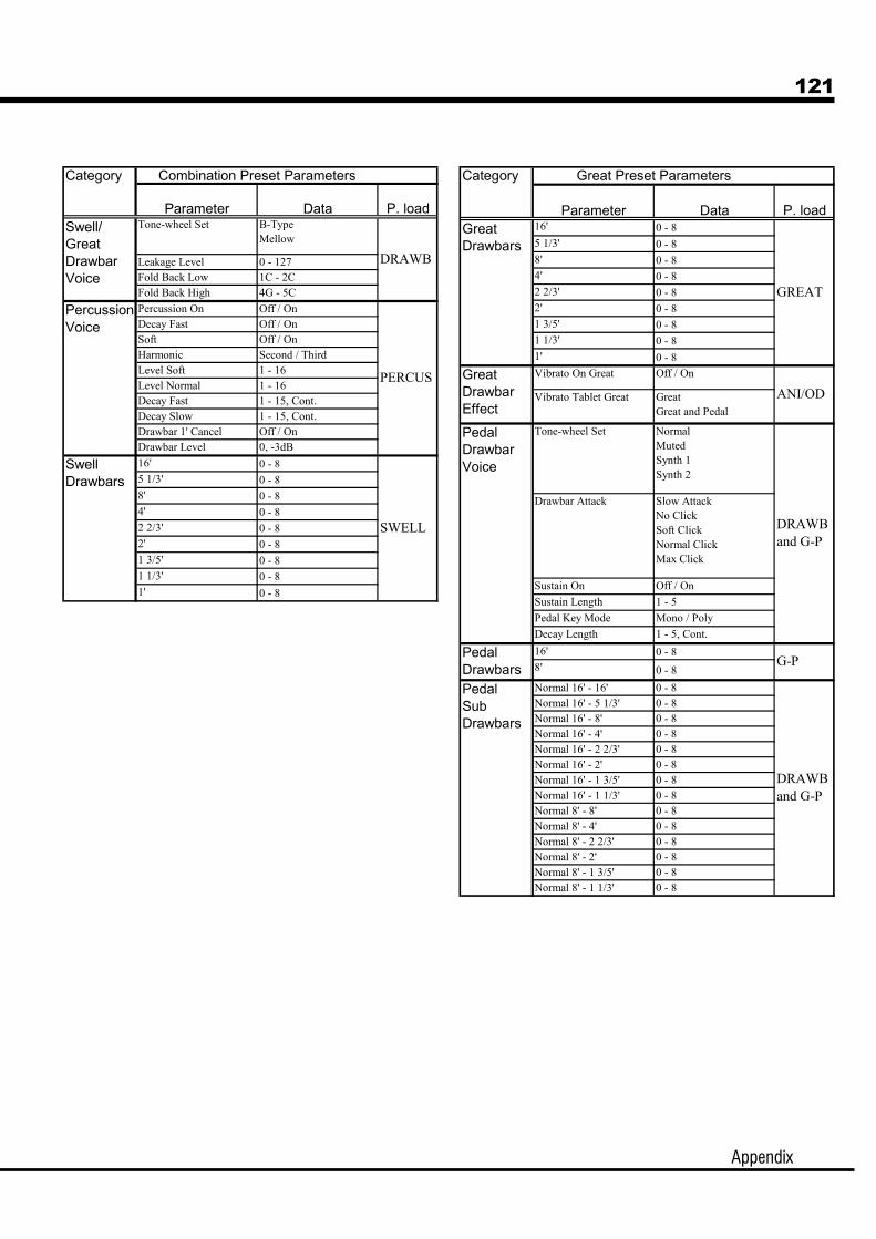
Appendix
121
Category
Parameter Data P. load16' 0 - 8
5 1/3' 0 - 88' 0 - 84' 0 - 82 2/3' 0 - 82' 0 - 81 3/5' 0 - 81 1/3' 0 - 81' 0 - 8
Vibrato On Great Off / On
Vibrato Tablet Great GreatGreat and Pedal
Tone-wheel Set NormalMutedSynth 1Synth 2
Drawbar Attack Slow AttackNo ClickSoft ClickNormal ClickMax Click
Sustain On Off / On
Sustain Length 1 - 5
Pedal Key Mode Mono / Poly
Decay Length 1 - 5, Cont.
16' 0 - 88' 0 - 8
Normal 16' - 16' 0 - 8Normal 16' - 5 1/3' 0 - 8Normal 16' - 8' 0 - 8Normal 16' - 4' 0 - 8Normal 16' - 2 2/3' 0 - 8Normal 16' - 2' 0 - 8Normal 16' - 1 3/5' 0 - 8Normal 16' - 1 1/3' 0 - 8Normal 8' - 8' 0 - 8Normal 8' - 4' 0 - 8Normal 8' - 2 2/3' 0 - 8Normal 8' - 2' 0 - 8Normal 8' - 1 3/5' 0 - 8Normal 8' - 1 1/3' 0 - 8
PedalSubDrawbars
DRAWBand G-P
PedalDrawbars
PedalDrawbarVoice
GreatDrawbars
Great Preset Parameters
GreatDrawbarEffect
ANI/OD
G-P
DRAWBand G-P
GREAT
Category
Parameter Data P. loadTone-wheel Set B-Type
Mellow
Leakage Level 0 - 127Fold Back Low 1C - 2CFold Back High 4G - 5C
Percussion On Off / OnDecay Fast Off / OnSoft Off / OnHarmonic Second / ThirdLevel Soft 1 - 16Level Normal 1 - 16Decay Fast 1 - 15, Cont.Decay Slow 1 - 15, Cont.Drawbar 1' Cancel Off / OnDrawbar Level 0, -3dB
16' 0 - 85 1/3' 0 - 88' 0 - 84' 0 - 82 2/3' 0 - 82' 0 - 81 3/5' 0 - 81 1/3' 0 - 81' 0 - 8
SwellDrawbars
Swell/GreatDrawbarVoice
SWELL
Combination Preset Parameters
PercussionVoice
DRAWB
PERCUS

122
Owner’s Manual
Leslie ParametersCategory
Parameter Data RangeName (10 Characters)
Slow Speed Horn 0, 24 - 318rpmSlow Speed Bass 0, 24 - 318rpmFast Speed Horn 0, 375 - 453rpmFast Speed Bass 0, 375 - 453rpmRise Time Horn 0.2 - 5.0sRise Time Bass 0.5 - 12.5sFall Time Horn 0.2 - 5.0sFall Time Bass 0.5 - 12.5sBrake Time Horn 0.2 - 5.0sBrake Time Bass 0.5 - 12.5sVolume Horn -12 - 0dBVolume Bass -12 - 0dBMic. Angle 0 - 180degMic. Distance 0.3 - 2.7mHorn Character Flat, Mid, DeepAmplifier Solidstate, TubeSpeaker Rotary Small
Rotary LargeStationary
Leslie Parameters
Cabinet
System ParametersCategory
Parameter Data Range DefaultExt.Leslie
Horn Mellow / Flat Mellow
Audio Pedal Both / Pedal Out Both
Key Scan Pedal Rebound 1-128 4
Display Lock Off / On Off
System Parameters
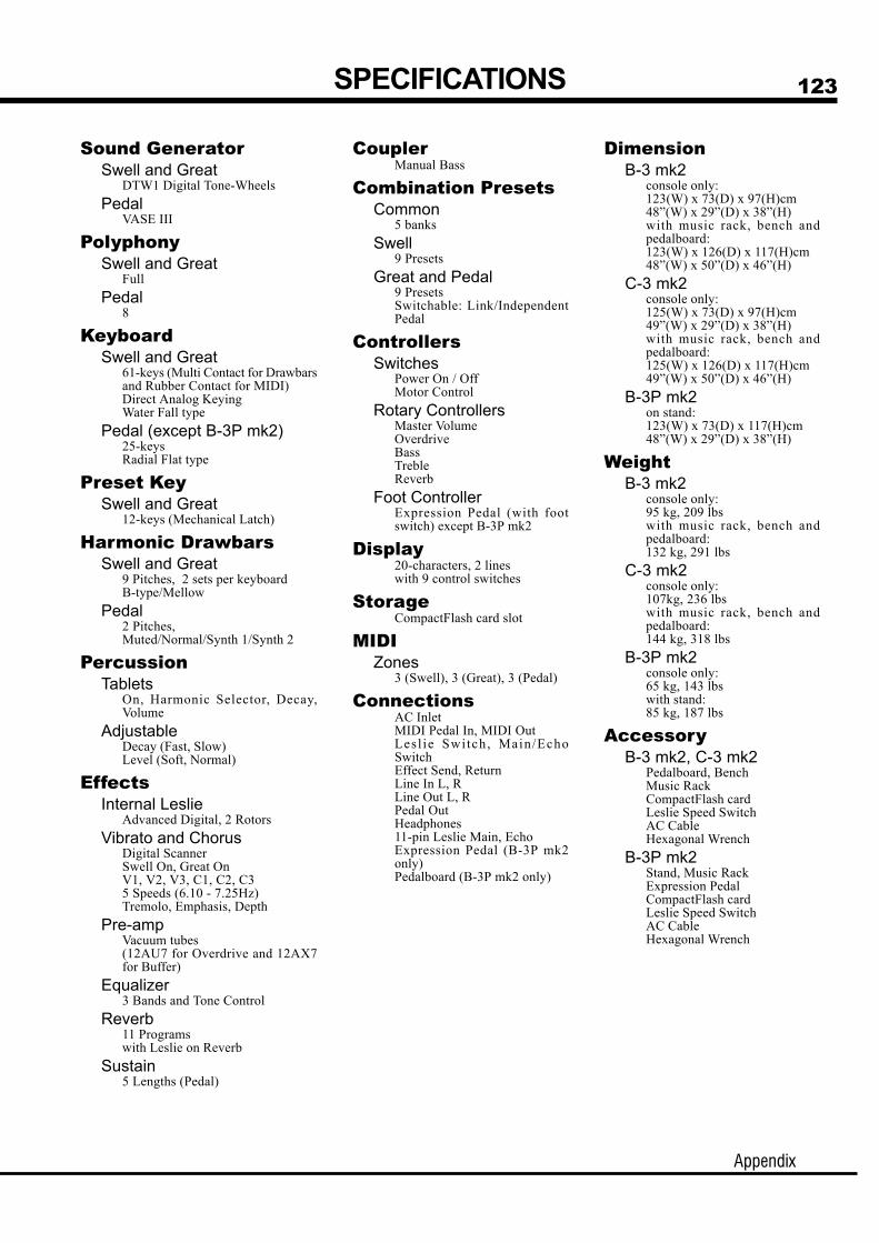
Appendix
123SPECIFICATIONS
Sound GeneratorSwell and Great
DTW1 Digital Tone-Wheels
PedalVASE III
PolyphonySwell and Great
Full
Pedal8
KeyboardSwell and Great
61-keys (Multi Contact for Drawbarsand Rubber Contact for MIDI)Direct Analog KeyingWater Fall type
Pedal (except B-3P mk2)25-keysRadial Flat type
Preset KeySwell and Great
12-keys (Mechanical Latch)
Harmonic DrawbarsSwell and Great
9 Pitches, 2 sets per keyboardB-type/Mellow
Pedal2 Pitches,Muted/Normal/Synth 1/Synth 2
PercussionTablets
On, Harmonic Selector, Decay,Volume
AdjustableDecay (Fast, Slow)Level (Soft, Normal)
EffectsInternal Leslie
Advanced Digital, 2 Rotors
Vibrato and ChorusDigital ScannerSwell On, Great OnV1, V2, V3, C1, C2, C35 Speeds (6.10 - 7.25Hz)Tremolo, Emphasis, Depth
Pre-ampVacuum tubes(12AU7 for Overdrive and 12AX7for Buffer)
Equalizer3 Bands and Tone Control
Reverb11 Programswith Leslie on Reverb
Sustain5 Lengths (Pedal)
CouplerManual Bass
Combination PresetsCommon
5 banks
Swell9 Presets
Great and Pedal9 PresetsSwitchable: Link/IndependentPedal
ControllersSwitches
Power On / OffMotor Control
Rotary ControllersMaster VolumeOverdriveBassTrebleReverb
Foot ControllerExpression Pedal (with footswitch) except B-3P mk2
Display20-characters, 2 lineswith 9 control switches
StorageCompactFlash card slot
MIDIZones
3 (Swell), 3 (Great), 3 (Pedal)
ConnectionsAC InletMIDI Pedal In, MIDI OutLesl ie Switch, Main/EchoSwitchEffect Send, ReturnLine In L, RLine Out L, RPedal OutHeadphones11-pin Leslie Main, EchoExpression Pedal (B-3P mk2only)Pedalboard (B-3P mk2 only)
DimensionB-3 mk2
console only:123(W) x 73(D) x 97(H)cm48”(W) x 29”(D) x 38”(H)with music rack, bench andpedalboard:123(W) x 126(D) x 117(H)cm48”(W) x 50”(D) x 46”(H)
C-3 mk2console only:125(W) x 73(D) x 97(H)cm49”(W) x 29”(D) x 38”(H)with music rack, bench andpedalboard:125(W) x 126(D) x 117(H)cm49”(W) x 50”(D) x 46”(H)
B-3P mk2on stand:123(W) x 73(D) x 117(H)cm48”(W) x 29”(D) x 38”(H)
WeightB-3 mk2
console only:95 kg, 209 lbswith music rack, bench andpedalboard:132 kg, 291 lbs
C-3 mk2console only:107kg, 236 lbswith music rack, bench andpedalboard:144 kg, 318 lbs
B-3P mk2console only:65 kg, 143 lbswith stand:85 kg, 187 lbs
AccessoryB-3 mk2, C-3 mk2
Pedalboard, BenchMusic RackCompactFlash cardLeslie Speed SwitchAC CableHexagonal Wrench
B-3P mk2Stand, Music RackExpression PedalCompactFlash cardLeslie Speed SwitchAC CableHexagonal Wrench
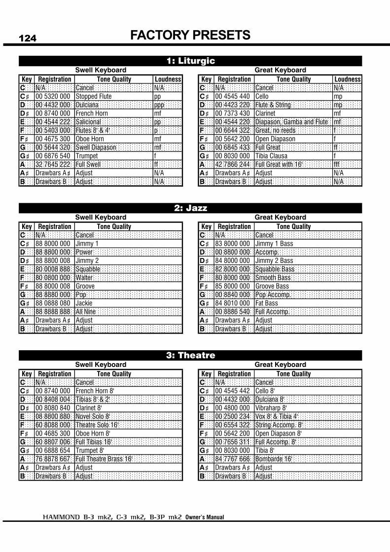
124
Owner’s Manual
FACTORY PRESETS
Key Registration Tone Quality Loudness Key Registration Tone Quality LoudnessC N/A Cancel N/A C N/A Cancel N/AC< 00 5320 000 Stopped Flute pp C< 00 4545 440 Cello mpD 00 4432 000 Dulciana ppp D 00 4423 220 Flute & String mpD< 00 8740 000 French Horn mf D< 00 7373 430 Clarinet mfE 00 4544 222 Salicional pp E 00 4544 220 Diapason, Gamba and Flute mfF 00 5403 000 Flutes 8' & 4' p F 00 6644 322 Great, no reeds fF< 00 4675 300 Oboe Horn mf F< 00 5642 200 Open Diapason fG 00 5644 320 Swell Diapason mf G 00 6845 433 Full Great ffG< 00 6876 540 Trumpet f G< 00 8030 000 Tibia Clausa fA 32 7645 222 Full Swell ff A 42 7866 244 Full Great with 16' fffA< Drawbars A< Adjust N/A A< Drawbars A< Adjust N/AB Drawbars B Adjust N/A B Drawbars B Adjust N/A
Key Registration Tone Quality Key Registration Tone QualityC N/A Cancel C N/A CancelC< 88 8000 000 Jimmy 1 C< 83 8000 000 Jimmy 1 BassD 88 8800 000 Power D 00 8800 000 Accomp.D< 88 8800 008 Jimmy 2 D< 84 8000 000 Jimmy 2 BassE 80 0008 888 Squabble E 82 8000 000 Squabble BassF 80 0800 000 Walter F 80 8000 000 Smooth BassF< 88 8000 008 Groove F< 85 8000 000 Groove BassG 88 8880 000 Pop G 00 8840 000 Pop Accomp.G< 88 0888 080 Jackie G< 84 8010 000 Fat BassA 88 8888 888 All Nine A 00 8886 540 Full Accomp.A< Drawbars A< Adjust A< Drawbars A< AdjustB Drawbars B Adjust B Drawbars B Adjust
Key Registration Tone Quality Key Registration Tone QualityC N/A Cancel C N/A CancelC< 00 8740 000 French Horn 8' C< 00 4545 442 Cello 8'D 00 8408 004 Tibias 8' & 2' D 00 4432 000 Dulciana 8'D< 00 8080 840 Clarinet 8' D< 00 4800 000 Vibraharp 8'E 08 8800 880 Novel Solo 8' E 00 2500 234 Vox 8' & Tibia 4'F 60 8088 000 Theatre Solo 16' F 00 6554 322 String Accomp. 8'F< 00 4685 300 Oboe Horn 8' F< 00 5642 200 Open Diapason 8'G 60 8807 006 Full Tibias 16' G 00 7656 311 Full Accomp. 8'G< 00 6888 654 Trumpet 8' G< 00 8030 000 Tibia 8'A 76 8878 667 Full Theatre Brass 16' A 84 7767 666 Bombarde 16'A< Drawbars A< Adjust A< Drawbars A< AdjustB Drawbars B Adjust B Drawbars B Adjust
1: LiturgicSwell Keyboard Great Keyboard
2: JazzSwell Keyboard Great Keyboard
3: TheatreSwell Keyboard Great Keyboard

Appendix
125
Key Registration Tone Quality Key Registration Tone QualityC N/A Cancel C N/A CancelC< 68 8000 000 The Gnome (Swell) C< 66 6666 888 The Gnome (Great)D 88 8800 000 Highway Star (Swell) D 00 5504 004 Highway Star (Great)D< 85 7303 000 Born To Be Wild (Swell) D< 00 5414 004 Born To Be Wild (Great)E 88 8888 888 Telstar (Swell) E 00 5678 763 Telstar (Great)F 88 8888 080 HM Soloist (Swell) F 88 8000 000 HM Soloist (Great)F< 77 7331 000 Funky Up (Swell) F< 00 6600 000 Funky Up (Great)G 80 8808 006 Full Tibias (Swell) G 00 8630 000 Full Tibias (Great)G< 88 6000 008 Groove 2 (Swell) G< 00 8855 000 Groove 2 (Great)A 87 8878 668 Theatre Brass (Swell) A 84 7767 666 Theatre Brass (Great)A< Drawbars A< Adjust A< Drawbars A< AdjustB Drawbars B Adjust B Drawbars B Adjust
Key Registration Tone Quality Key Registration Tone QualityC N/A Cancel C N/A CancelC< C<D DD< D<E EF FF< F<G GG< G<A AA< Drawbars A< Adjust A< Drawbars A< AdjustB Drawbars B Adjust B Drawbars B Adjust
Swell Keyboard Great Keyboard
4: ShowCaseSwell Keyboard Great Keyboard
5: User
This Bank introduces you this organ's advanced features.Each Preset of this Bank calls out various parameters other than Drawbar registration, such as Leslie, Overdrive.

126
Owner’s Manual
127
Owner’s Manual
SERVICE
Hammond maintains a policy of continuously improving and upgrading its instruments and therefore reserves theright to change specifications without notice. Although every attempt has been made to insure the accuracy of thedescriptive contents of this Manual, total accuracy cannot be guaranteed.Should the owner require further assistance, inquiries should first be made to your Authorized Hammond Dealer.If you still need further assistance, contact Hammond at the following addresses:
In the United States Contact:
HAMMOND SUZUKI USA, Inc.733 Annoreno Dr.Addison, IL 60101UNITED STATES
In Europe contact:
HAMMOND SUZUKI EUROPEB.V.
IR. D.S. Tuynmanweg 4A4131 PN Vianen
THE NETHERLANDS
All other countries contact:
HAMMOND SUZUKI Ltd.25-11, Ryoke 2 Chome,Naka-ku, Hamamatsu430-0852 (Shizuoka)
JAPAN
E-mail: [email protected]: www.hammondsuzuki.com
Technical materials are available and can be obtained by mailing a request to the appropriate address listed abovemarked ATTENTION: SERVICE DEPARTMENT.
Manufacturer:SUZUKI MUSICAL INSTRUMENT MFG. CO., Ltd.
25-12, Ryoke 2 Chome, Naka-ku,Hamamatsu 430-0852 (Shizuoka)
JAPAN
Website:www.hammondorganco.com
Website: www.suzuki-music.co.jp

HAMMOND SUZUKI, LTD., Hamamatsu, Japan Printed in Japan00457-40154
V1.00-081105
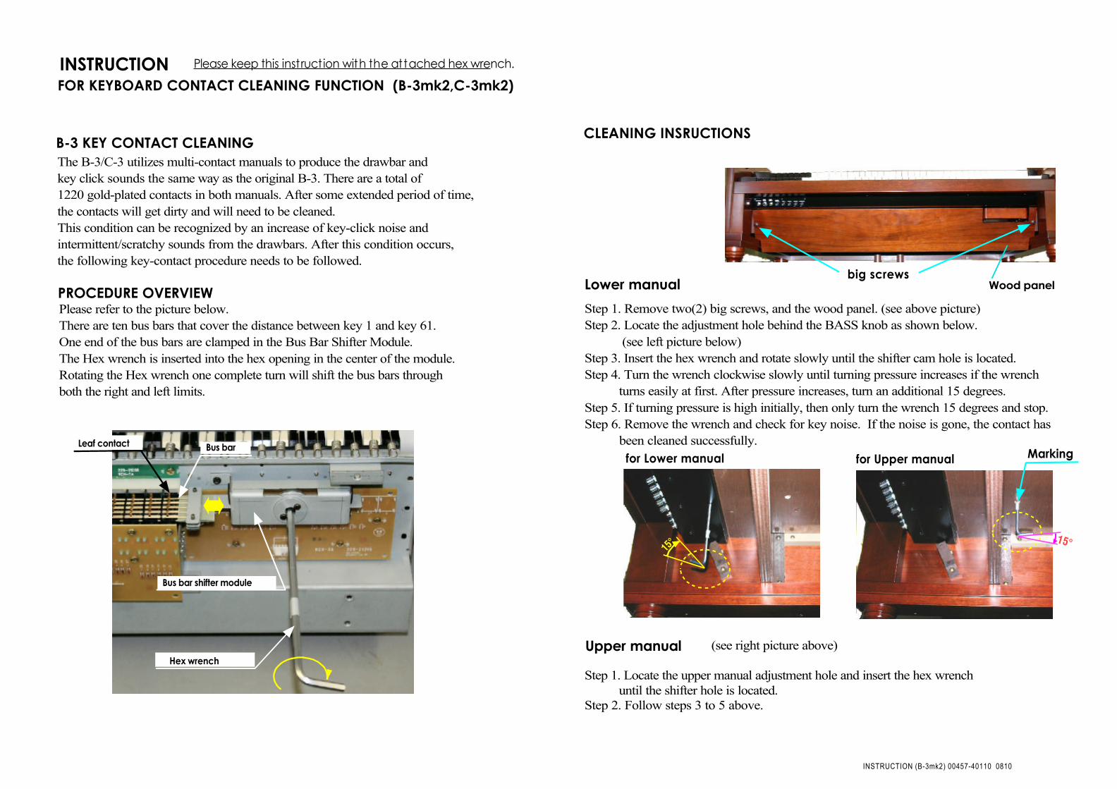
Step 1. Remove two(2) big screws, and the wood panel. (see above picture)Step 2. Locate the adjustment hole behind the BASS knob as shown below. (see left picture below)Step 3. Insert the hex wrench and rotate slowly until the shifter cam hole is located.Step 4. Turn the wrench clockwise slowly until turning pressure increases if the wrench turns easily at first. After pressure increases, turn an additional 15 degrees.Step 5. If turning pressure is high initially, then only turn the wrench 15 degrees and stop.Step 6. Remove the wrench and check for key noise. If the noise is gone, the contact has been cleaned successfully.
(see right picture above)
Step 1. Locate the upper manual adjustment hole and insert the hex wrench until the shifter hole is located.Step 2. Follow steps 3 to 5 above.
INSTRUCTION FOR KEYBOARD CONTACT CLEANING FUNCTION (B-3mk2,C-3mk2)
PROCEDURE OVERVIEW
CLEANING INSRUCTIONS
Lower manualbig screws
Wood panel
for Lower manual
Upper manual
for Upper manual Marking
Please keep this instruction with the attached hex wrench.
The B-3/C-3 utilizes multi-contact manuals to produce the drawbar and key click sounds the same way as the original B-3. There are a total of 1220 gold-plated contacts in both manuals. After some extended period of time, the contacts will get dirty and will need to be cleaned. This condition can be recognized by an increase of key-click noise and intermittent/scratchy sounds from the drawbars. After this condition occurs, the following key-contact procedure needs to be followed.
B-3 KEY CONTACT CLEANING
Please refer to the picture below.There are ten bus bars that cover the distance between key 1 and key 61.One end of the bus bars are clamped in the Bus Bar Shifter Module.The Hex wrench is inserted into the hex opening in the center of the module.Rotating the Hex wrench one complete turn will shift the bus bars throughboth the right and left limits.
15° 15°
INSTRUCTION (B-3mk2) 00457-40110 0810
Bus barLeaf contact
Bus bar shifter module
Hex wrench
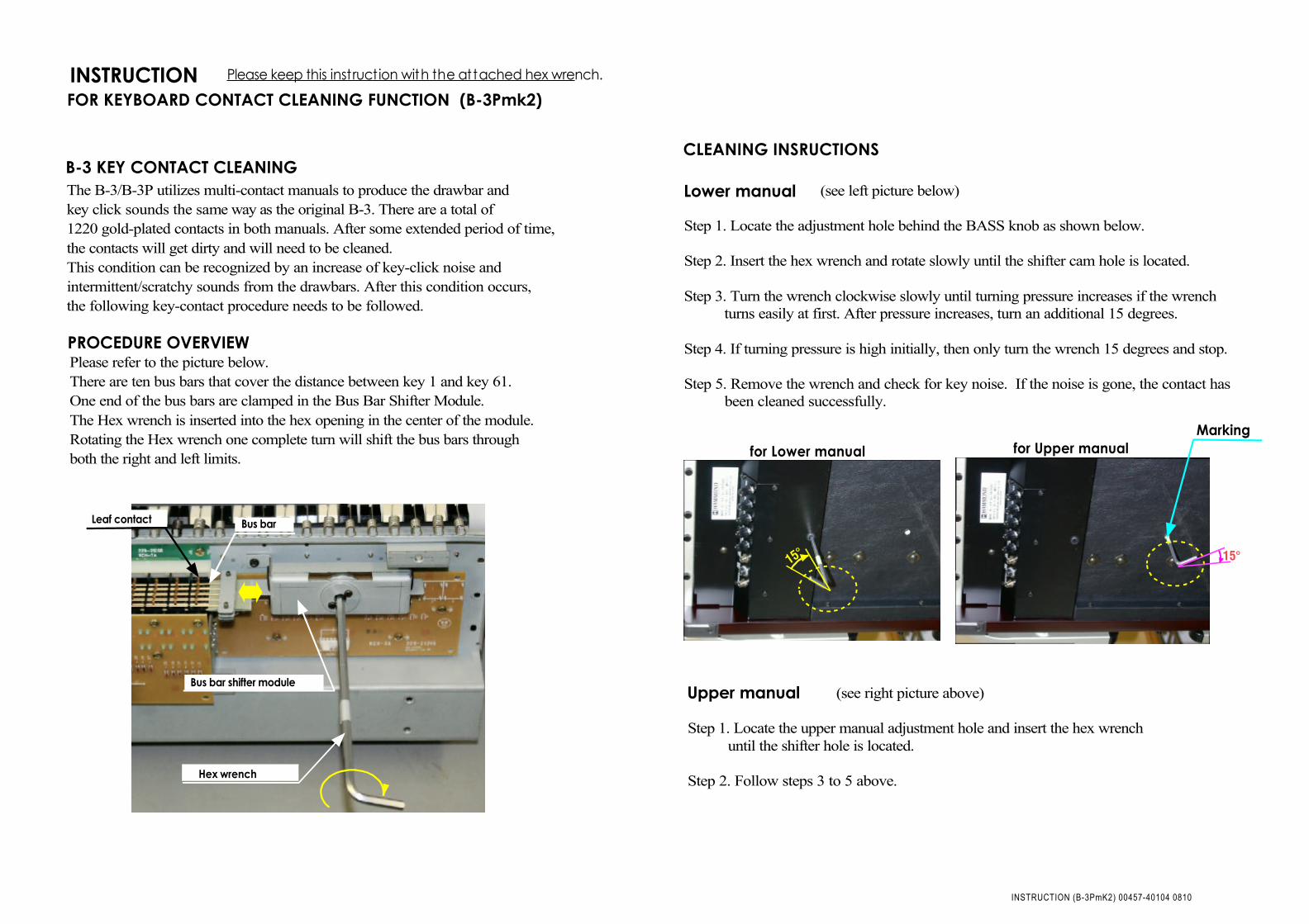
(see left picture below)
Step 1. Locate the adjustment hole behind the BASS knob as shown below.
Step 2. Insert the hex wrench and rotate slowly until the shifter cam hole is located.
Step 3. Turn the wrench clockwise slowly until turning pressure increases if the wrench turns easily at first. After pressure increases, turn an additional 15 degrees.
Step 4. If turning pressure is high initially, then only turn the wrench 15 degrees and stop.
Step 5. Remove the wrench and check for key noise. If the noise is gone, the contact has been cleaned successfully.
(see right picture above)
Step 1. Locate the upper manual adjustment hole and insert the hex wrench until the shifter hole is located.
Step 2. Follow steps 3 to 5 above.
INSTRUCTION FOR KEYBOARD CONTACT CLEANING FUNCTION (B-3Pmk2)
PROCEDURE OVERVIEW
CLEANING INSRUCTIONS
Lower manual
for Lower manual
Upper manual
for Upper manualMarking
Please keep this instruction with the attached hex wrench.
The B-3/B-3P utilizes multi-contact manuals to produce the drawbar and key click sounds the same way as the original B-3. There are a total of 1220 gold-plated contacts in both manuals. After some extended period of time, the contacts will get dirty and will need to be cleaned. This condition can be recognized by an increase of key-click noise and intermittent/scratchy sounds from the drawbars. After this condition occurs, the following key-contact procedure needs to be followed.
B-3 KEY CONTACT CLEANING
Please refer to the picture below.There are ten bus bars that cover the distance between key 1 and key 61.One end of the bus bars are clamped in the Bus Bar Shifter Module.The Hex wrench is inserted into the hex opening in the center of the module.Rotating the Hex wrench one complete turn will shift the bus bars throughboth the right and left limits.
15° 15°
INSTRUCTION (B-3PmK2) 00457-40104 0810
Bus barLeaf contact
Bus bar shifter module
Hex wrench