handbook for process plant project engineers - peter watermeyer
DESCRIPTION
TRANSCRIPT


This page intentionally left blank

iContents
Handbook for Process PlantProject Engineers
by
Peter Watermeyer
Professional Engineering Publishing LimitedLondon and Bury St Edmunds, UK

ii ContentsFirst published 2002
This publication is copyright under the Berne Convention and theInternational Copyright Convention. All rights reserved. Apart from any fairdealing for the purpose of private study, research, criticism, or review, aspermitted under the Copyright Designs and Patents Act 1988, no part may bereproduced, stored in a retrieval system, or transmitted in any form or by anymeans, electronic, electrical, chemical, mechanical, photocopying, recordingor otherwise, without the prior permission of the copyright owners.Unlicensed multiple copying of this publication is illegal. Inquiries should beaddressed to: The Publishing Editor, Professional Engineering PublishingLimited, Northgate Avenue, Bury St Edmunds, Suffolk, IP32 6BW, UK.
© P Watermeyer
ISBN 1 86058 370 9
A CIP catalogue record for this book is available from the British Library.
The publishers are not responsible for any statement made in thispublication. Data, discussion, and conclusions developed by the Authorare for information only and are not intended for use withoutindependent substantiating investigation on the part of the potentialusers. Opinions expressed are those of the Author and are not necessarilythose of the Institution of Mechanical Engineers or its publishers.
Printed by Cromwell Press, Trowbridge, Wiltshire, UK

This page intentionally left blank

iiiContents
Foreword ixAcknowledgements x
Chapter 1 Introduction 11.1 What’s so special about process plant projects? 11.2 The structure and components of this book 31.3 Methodology of presentation 51.4 Getting it right 7
First Cycle – A Process Plant and a ProjectChapter 2 A Process Plant 132.1 Basic process design elements 132.2 The processed materials and the process 182.3 The process design/detail design interface 20
Chapter 3 A Project and its Management: A Brief Overview 233.1 The project 233.2 Starting the project 253.3 Managing the project 27
Chapter 4 The Engineering Work and Its Management 314.1 Planning the engineering work 314.2 Doing the engineering work 404.3 Managing schedule, cost, and quality 414.4 Co-ordinating engineering work 444.5 Management of engineering resources 46
Second Cycle – EnvironmentChapter 5 The Project’s Industrial Environment 515.1 The industry and the client 515.2 The client and the project management 555.3 The process plant project industry:
the ‘indirect cost’ of a plant 56
Chapter 6 The Commercial Environment 596.1 Principles of procurement and contract 59
Chapter 7 The Contracting Environment 657.1 Ways of building a plant 657.2 The engineering contractor 707.3 The project engineer 727.4 Conclusion 75
Contents

iv Contents
Chapter 8 The Economic Environment 778.1 Plant profitability 778.2 Lifecycle considerations and ‘trade-off’ studies 788.3 The real world of costs and values 828.4 Project engineering and management work 83
Third Cycle – Conceptual DevelopmentChapter 9 Studies and Proposals 919.1 Feasibility studies 919.2 Proposals 949.3 Estimating project costs 949.4 Risk 979.5 Accuracy 999.6 Contingency 101
Chapter 10 Plant Layout and Modelling 10510.1 Layout 10510.2 Design presentation and modelling 112
Chapter 11 Value Engineering and Plant Optimization 11711.1 Value engineering 11811.2 Plant optimization models 120
Chapter 12 Hazards, Loss, and Safety 12312.1 Hazard identification 12412.2 Designing for safety 12712.3 Commissioning 13112.4 Plant modifications 132
Fourth Cycle – Engineering Development and DetailChapter 13 Specification, Selection, and Purchase 13513.1 Procurement 13513.2 Specification 138
13.2.1 Specification as a document for bidding 13813.2.2 Specification as a reference for work performance 141
13.3 The selection of equipment 14113.4 Technical appraisal of equipment bids 14313.5 Inspection and quality control 14513.6 Planning inspection work 14813.7 Expediting 150
Chapter 14 Fluid Transport 15314.1 A brief note on liquid-pumping systems design 15314.2 Gases 162

vContents
14.3 Piping engineering and its management 16714.4 Some concluding comments on piping layout for
pumps and compressors 170
Chapter 15 Bulk Solids Transport 17315.1 Bulk solids flow 17315.2 Conveyors 17515.3 Feeders 18115.4 Safety and environmental health 183
Chapter 16 Slurries and Two-Phase Transport 18516.1 Slurry transport 18516.2 Piping design 18816.3 Tanks and agitation 18916.4 Pneumatic conveying 19116.5 Pipework reactions 192
Chapter 17 Hydraulic Design and Plant Drainage 19517.1 Hydraulic design 19517.2 Plant drainage 201
Chapter 18 Observations on Multi-Discipline Engineering 20318.1 Structural design considerations 20318.2 Plant and equipment loads 20518.3 Civil engineering 20718.4 Electrical engineering 20918.5 Instrumentation and control 212
Chapter 19 Detail Design and Drafting 21719.1 Structures 21819.2 Piping 22119.3 Vessels 22719.4 Chutes, bins, and hoppers 22919.5 Civil design 23019.6 Instrumentation and control 23319.7 Electrical design 23619.8 Other technical specialities and consultants 23819.9 Overview of the design process 23919.10 General arrangement drawings and models 240
Chapter 20 Traditional Documentation Control 243
Fifth Cycle – More on ManagementChapter 21 The Organization of Work 24921.1 Packaging work 249

vi Contents
21.2 Procedures 254
Chapter 22 Construction 25722.1 Survey and setout 25822.2 Site management 25822.3 Technical information for construction 25922.4 Site materials management 26022.5 Heavy lifts 26122.6 The ‘site and office’ relationship 262
Chapter 23 Construction Contracts 26523.1 Structuring contracts 26523.2 Structuring payment to contractors 26923.3 Claims 270
Chapter 24 Commissioning 27324.1 Safety during commissioning 276
Chapter 25 Communication 277
Chapter 26 Change and Chaos 28126.1 Change 28126.2 Chaos 283
Chapter 27 Fast-Track Projects 28927.1 Case study A: Fabulous Fertilizers’ new plant 29227.2 Case study B: Magnificent Metals’ new gold plant 293
Chapter 28 Advanced Information Management Systems 297
Final Cycle – Strategies for SuccessChapter 29 Project Strategy Development 30529.1 Is the target correct? 30729.2 How do we get there? 30829.3 What are the major problems? 309
Chapter 30 Key Issues Summary 31130.1 Key project or study issues at the conceptual stage 31130.2 Key issues at the project execution phase 31130.3 Key issues for the conduct of the individual
engineer or engineering business unit 31330.4 General business issues 313
Appendix 1 Jargon 315A1.1 Definition of design parameters 316

viiContents
Appendix 2 Design Criteria Checklist 317A2.1 Plant performance 319A2.2 Plant site 319A2.3 The process 319A2.4 Basic plant design features 320A2.5 Design features for equipment (mechanical,
instrumentation, and electrical) 320A2.6 Design methodology and standardization 320A2.7 Design verification and approval plan 321A2.8 Design and plant documentation for client 321
Index 323

This page intentionally left blank

viii Contents
How Did That Happen – Engineering Safety and Reliability
IMechE Engineers’ Data Book(Second Edition)
Improving Maintainability andReliability through Design
A Practical Guide to EngineeringFailure Investigation
Process Machinery – Safety andReliability
Plant Monitoring and MaintenanceRoutines (IMechE Seminar)
W Wong
C Matthews
G Thompson
C Matthews
W Wong (Ed.)
1 86058 359 8
1 86058 248 6
1 86058 135 8
1 86058 086 6
1 86058 046 7
1 86058 087 4
Related Titles
For the full range of titles published byProfessional Engineering Publishing contact:
Marketing DepartmentProfessional Engineering Publishing Limited
Northgate AvenueBury St Edmunds
SuffolkIP32 6BW
UKTel: +44 (0)1284 724384Fax: +44 (0)1284 718692
Website: www.pepublishing.com

ixContentsForeword
Project engineering comprises the orchestrated integration of allengineering disciplines to achieve a commercially defined projectobjective. The quality and effectiveness of project engineering are keycomponents of process plant design and construction, a business whichinvariably requires complex multi-disciplinary design input and focusedcustomer and commercial awareness.
Courses in the individual disciplines such as civil, mechanical, andchemical engineering are offered by many universities and otherinstitutions. By contrast, the art of project engineering is usuallyacquired the hard way, through practical involvement in projectexecution. Unfortunately, much of the necessary experience is too oftenpainfully gained by learning from expensive mistakes.
Peter Watermeyer has a keen interest in analysing the causes ofsuccess, failure, mediocrity, and excellence in project execution. He seesthese as a function of not only the performance and management of theengineering work, but also of the way that work and project teams arestructured and orientated in relationship to their whole environment.Peter has a wealth of practical experience in the industry. He spent 15years in the power, hydrocarbons, and process machinery industriesbefore joining Bateman, where he has spent over 20 years in theengineering and management of process plant projects, mainly in theinternational mining and petroleum industries.
This book, which is based on the knowledge, skill, and diverseexperience of a master of the art will, I believe, prove to be of great valuein guiding aspiring and less experienced project engineers towardsachieving full professional competence in this challenging arena.
Dr John P Herselman, DrIng, Dipl-Ing, BSc (Chem Eng), FIODExecutive Chairman, Bateman BV

This page intentionally left blank

xiContentsAcknowledgements
The illustrations in this book are by Natalie Watermeyer and thephotographs and drawings are reproduced with permission fromBateman Projects Ltd.
I am grateful to Phillip Ashworth, for his review and guidance onthe revision to the original text. I would also like to thank the editorialstaff of Professional Engineering Publishing, and in particular thecommissioning editor Sheril Leich and the co-ordinating editor MandyKingsmill, for their very professional work.

This page intentionally left blank

Introduction 1
Chapter 1
Introduction
This book is intended to assist people who design and build processplant, and people who participate in multi-disciplinary engineeringprojects in general. The book is aimed in particular at the project engineer,or team of lead engineers, who inevitably hold such projects together,being at the heart of the information generation system which shapesand guides the project.
The design and construction of process plant covers an exceedinglywide field of performance and knowledge. Considering engineeringtopics alone, those which impact process plant design include the workof very many specialist technical branches. But this is only part of whathas to be considered in successful project engineering. Interwoven withthe engineering and design of the plant are many commercial, construc-tional, financial, and social considerations. It may be satisfying for thetechnical purist to focus exclusively on engineering issues, but theengineer who does so is likely either to be limited to a subordinate role,or to be part of an unsuccessful enterprise – engineering considered onits own becomes an academic pastime.
The content of the book is therefore intended to address that mixedbag of technical, commercial, managerial, and behavioural issues whichconstitute the actual job content of the practising engineer, and arepeculiar to this industry.
1.1 What’s so special about process plant projects?
In some cases – nothing! A relatively small and simple project canusually be executed by a single experienced engineer with a minimum offuss, and without complex procedures or strategy. This is especially the

2 Handbook for Process Plant Project Engineers
case for plants which are very similar to existing units. Within thefollowing text may be found some helpful aspects of technical advicefor such projects, but the work must not be over-complicated. Anyhigher-level issues of strategy and management are best addressed(if at all) at the level of organization which encompasses the smallproject, for example the corporation which requires the project, or acontracting organization which delivers such projects. The followingtext is primarily addressed at relatively large and complex projects,requiring the interaction of a number of skills – technical, commercial,and constructional.
Compared to the general field of engineering design and construction,the main differentiating factors which have to be addressed in theseprojects are the following.
• The unique design of each plant is the inevitable consequence of theneed to optimize each application to its unique circumstances offeedstock, product, capacity, and environment.
• Plants are built around hundreds of items of proprietary processingequipment. The plant design must interface exactly with theoperational characteristics and dimensions of these individual items.The interface information can only be finalized when the commercialagreements with equipment suppliers have been concluded.1
• Both the plant design and its construction employ many types ofspecialist, who must interact at thousands of interfaces (and oftenwork simultaneously in the same plant space envelope) to produce aco-ordinated product.
• Plant operation can be hazardous. The elimination or control ofhazards, and the establishment of safe operating practices, areprerequisites of plant operation, requiring priority attention duringplant design. Environmental impact is also invariably an issue.
• Technology development is rapid and continuous. This greatlyimpacts on the uniqueness of process and plant design (the first itemabove), but also often impacts on project execution – there is often adesire to accommodate changes while design and construction are inprogress.
1 This is at least the common practice in free-market economies. In communist countries,it was (and still is) often the practice to ‘centralize’ equipment designs, so that the plantdesigner can simply choose a completely detail-designed equipment item from acatalogue. This simplifies the plant designer’s job,but often at great cost at the constructionstage, when there is no commitment from a supplier to match the project programme orbudget. Also, it shifts responsibility for ‘fitness for purpose’ of the item.

Introduction 3
• The project schedule cannot be generated in any mechanisticfashion. Invariably, the critical path can be shortened almost adinfinitum by taking various shortcuts (in other words, by changingthe schedule logic – not just by employing more resources or workingfaster). These possible shortcuts come at a cost or risk, which mustbe balanced against the benefits.
• The nature of the industry served by process plant usually puts ahigh premium on early plant completion and operation.
• The plant has to be constructed on site, to suit its site, wherever thatmay be.
The degree to which these and other features are present, together withthe more obvious comparisons of size, cost, and complexity, dictate theintensity of the challenge to the project team. All of these features haveto be addressed during the plant engineering and its follow-up.
1.2 The structure and components of this bookThe main objective of this book is to give guidance on how the projectengineer’s work is carried out in practice. We have therefore to considerhow all items of information interact, and how they are broughttogether in each practical situation. This is a distinctly different objectivefrom that of a technical reference book, such as Perry’s ChemicalEngineer’s Handbook. This is a recommended reference for any engineerin the process plant field, and contains a wealth of information, but it istargeted and indexed by technical subject. We need a different structurehere, in which the sequence of information is important and is project-related. It is convenient to address the structure at four levels.
In defining these levels, an immediate pitfall can be identified andshould be avoided. In organizational and management terminology,invariably there is a high and a low level. This should not be confusedwith relative importance – all of the organization components areimportant. Within each level, there are likely to be relatively less andmore important functions for a given project, but a project can bejeopardized just as easily by poor detail design as by poor management.
Subject to this qualification, the base tier, level one, consists of theactivities of detailed design, procurement of parts, delivery to site,construction, and commissioning, and all of these will be addressed.Inevitably in an integrating text such as this, most topics have to bediscussed at a relatively superficial level, concentrating on those facetswhich are more essential, either to the interactions with the whole, orbecause of relatively high individual impact to the project and the plant.
4 Handbook for Process Plant Project Engineers
At the level above, level two, reside the technical focus and projectcontrol, which give direction to all the detailed work. The centrepieceof this is the process technology package. The technological contentof such packages is outside the scope of this book – it is the domainof many experts and organizations, embracing diverse fields of technicalspecialization such as catalytic conversion and hydro-metallurgy, andniches within these fields which yet consume entire careers. We willrather (and briefly) address the generalized make-up of such packages,of how they relate to the plant to be built and to the project aroundthem. In addition, we will discuss the system of engineering and infor-mation management (also at level two), which governs the performanceof level one activities.
Not particularly addressed at level two, because of the focus of thisbook, are the methodologies of managing procurement, logistics,contracts, finance, and construction. The reader with greater projectmanagement aspirations is advised to refer to specialized texts on thesesubjects. We will, however, discuss the principal interfaces withengineering work and its management.
At level three, we have a management system for the entire project.This is conventionally broken down into three or four components,namely management of scope, quality, cost, and schedule. (Scope andquality may be regarded as a single issue, a practice not recommendedby the author.) Health and safety considerations may properly also bemanaged at this overview level, and must be included in any such text.
At level four, there is only one item, project strategy. This has toensure that the project is correctly conceived (technically, commercially,economically, socially) and embodies the skeleton of the over-archingplan which will ensure that the goods are delivered in the optimumfashion. Inevitably the strategy must deal with the issues of relationshipmanagement between the principal stakeholders, for example the plantowner (usually, a complexity of people and interests) and contractors,including possibly a single lump sum or managing contractor, and avariety of sub-contractors and suppliers. The strategies are bound to bedifferent for each stakeholder, reflecting the basic question of ‘What doI want out of this project?’
There is a significant body of professional opinion that such con-siderations of strategy are not appropriate in the context of what shouldbe the technical field of engineering. (In the author’s experience, thereare also several senior executives who are relatively ignorant of the linksbetween engineering and strategy, and feel quite threatened!) There arethose who argue that management of large projects, whether or not

Introduction 5
centred on multi-disciplinary engineering, is primarily a matter ofproject management practice, and can be quite separately treated assuch. Both of these views can be dangerous. From level one to levelfour, there are common threads, mainly of engineering information andits development, which have to be taken into account when makingmanagement decisions. The understanding and maintenance of thesethreads, many of whose origins are at the detail level, are the essence ofthe discipline of project engineering.
The interaction between project strategy and engineering executionoperates in two directions. It will be seen within this text that the adoptionof project strategy – including for instance the structure of the relationshipbetween client and contractor – has major implications for the way inwhich engineering is optimally conducted. In reverse, the best projectstrategy (for each party) is likely to depend on some of the engineeringrealities.
The technical content of this book posed a particular challenge ofselection and condensation. Nearly every topic could be expanded intoseveral volumes, and must in practice be covered by specialist engineerswith far more knowledge than is presented. The intentions behind theinformation presented are twofold. Firstly, to include just sufficientinformation for a generalist (the project engineer) to manage the specialists,or to assist the specialists to co-ordinate with each other and find thebest compromises. Secondly, to include some of the author’s ownexperience (spanning some 30 years) of simple but important itemswhich do not seem to be conveniently presented in textbooks or standards,but which can prove important and costly.
1.3 Methodology of presentation
Project engineers have traditionally learnt much of their job-knowledgeby experience. The mainly technical aspects can be taught in isolation asan academic subject, but even these have to be tempered by experience,to match theory to application. The behavioural and managementaspects of job performance are even more dependent on the acquisitionof relevant experience. Through a few project cycles in relatively juniorroles, engineers have gradually broadened their skills and their under-standing of what is going on, inside and outside of the project team, andbecome aware of the consequences of design decisions and of the wayactions and events interact. They have learned to recognize problems,and learned some standard solutions and how to choose the best

6 Handbook for Process Plant Project Engineers
solution for the circumstances. They have also absorbed something ofthe culture of their industry, and learnt how to behave and influenceothers, to make the best of their working relationships. They havebecome ready for a leading or management role.
It is our objective here to produce a text which accelerates this processof learning, and enhances it by trying to transfer some of the author’s ownexperience and retrospective analysis of successes and failures. Surely theprocess of learning by experience can be accelerated, and some of the painreduced.
A limitation of trying to synthesize such a learning process is that abalanced progression must be achieved, in which all the interactingsubjects are advanced more or less in parallel. It is no good giving adissertation on the merits and techniques of compressing project schedulesunless the more normal schedule practice and its logic are understood. Itis equally fruitless (and boring, and unlikely to be absorbed) to discuss thefiner points of project management, let alone strategy development, untilit is understood what are the work components (and their characteristics)which have to be managed and optimized.
The book has therefore been set out into six cycles, each targeted at adifferent and progressive stage of development. The first cycle consists ofan overview of a process plant, the process technology package, a verybrief outline of the management of a project to build a plant, and a briefdescription of the engineering work and its management. The secondcycle looks at the project environment, in particular some non-engineeringfactors which influence the work of the project. The third cycle is aboutproject initiation and conceptual development. This becomes possiblewhen the nature of the project and its environment are understood. Wehave also chosen to address the subject of hazards and safety at this point.The fourth cycle addresses plant engineering technical issues, at a moredetailed level, and is the largest component of the book. The fifth cycle isconcerned with project engineering and management issues which needa particular emphasis in this industry, leading up to a final cycle whichdiscusses strategy development.
It may be noticed that the two structures, of level and of cyclical develop-ment, are not strictly parallel, but compare more like a traditional four-cylinder engine firing cycle of 2-1-3-4. Even this analogy is somewhatmisleading. There is no single direction leading to strategic understanding,but rather a matrix where every part depends more or less on every otherpart, and the strategy requires a knowledge of all the parts. Strategicperformance, without detailed performance, is of no value whatever, andboth continue to evolve and require a continuous learning process.

Introduction 7
Turning to the basics of the format of presentation, in an endeavourto provide a text that can be useful for on-the-job reference, the generalmechanism employed is the checklist. Wherever possible, the text hasbeen formatted into bullets, which are intended to provide a structuredapproach to the common practical situations, by helping the engineerboth to plan his2 approach and to check that he is addressing all essentialfacets.
1.4 Getting it right
The basic project methodology advocated in this book is to start aproject by looking as widely as possible at the choices presented, evaluatethe full consequences of those choices, and then develop a strategy tomake the best of the opportunities and eliminate the risks. The strategyis further developed in a structured fashion, leading to detailed plansand methodologies, which are based on solid experience that has beenproven to give manageably acceptable results.
It all sounds very simple. And yet, so many individual engineers, andorganizations of engineers, fail to produce acceptable results. Individualintelligent and well-educated engineers fail to rise above mediocrity, andwhole engineering organizations become obsolete and disappear. Othersprosper: some seemingly by sheer luck, by being in the right place at theright time, but mostly by getting the right balance between having agood strategy, based on recognition of personal objectives, and thediligent deployment of sound skills.
There really is not much more to be said about the path to success,but it is quite easy to comment on the failures. A few main categoriesare worth mentioning.
• Bad luck. As real calamities such as political risk or natural disastercan and should be insured against, this should rather be described asthe occasional, unfortunate consequence of excessive risk. Somedegree of technical risk is inevitable for developing technologies,without which a technically based enterprise is anyway unlikely toflourish. The same goes for commercial risk, which is necessary toseize opportunities. The key is to have a considered risk management
2 Throughout the text, the male gender is intended to include the female. This is donepurely for the purposes of simplification.

8 Handbook for Process Plant Project Engineers
plan, which recognizes and excludes risks whose possible conse-quences are unacceptable, and balances manageable risk againstreward. This should lead to ample compensation in the long run. Inconclusion, this is an element of strategy.
• Lack of knowledge (job-information, know-how or commercialpractice) or of diligence. The following text should hopefully impartenough knowledge at least to assess how much additional expertiseand information is required for a given project. No remedy is avail-able for the second shortcoming.
• Setting of unreasonable targets. The detail of how this sometimescomes about, and how it can be recognized, will be addressed in thetext – it is really a relationship issue. Occasionally, social or politicalfactors, or ‘brain-dead’ enterprise directors, spawn projects whichinherently have little or no real economic return – a conclusion whichis hidden by an unreasonable target. Stay clear of these projects!
• Running in reactive mode. Here is an example. A natural resourcescompany needs a new process unit to enhance its product slate. Itstechnical manager (the client) is appointed to oversee the project. Heis a leading expert on the technology application, and Knows WhatHe Wants, but is not terribly good at communicating it – or listeningfor that matter. In due course a project team is assembled under aproject manager, including a process design team and a lead engineer
Fig. 1.1 ‘... a good strategy, based on the recognition of personalobjectives, and the diligent deployment of sound skills’

Introduction 9
for each discipline. A planner is recruited. He loses no time in gettingplans from each discipline, and putting them together into an overallnetwork. Unfortunately, he does not fully understand the interactionbetween disciplines of detailed engineering information, the potentialconflicts, or how they may be resolved. The client dictates that theproject schedule must be 16 months to commissioning, because heheard that was achieved somewhere else, and the planner duly jockeysthe project schedule around to reflect this. The client also dictates theproject budget. This includes no contingency, because he KnowsWhat He Wants, and contingencies will only encourage the projectteam to believe that error and waste are acceptable.As time goes on:
– Engineering gets further and further behind schedule, as eachdiscipline in turn is unable to start or complete jobs because ofthe unavailability of information from equipment vendors andother disciplines.
– Design and procurement decisions are endlessly delayed,because the client is not offered what he Wants, and expects theproject team simply to make up the delays. They do not.
– Many of the project drawings become full of revisions, holds,and – inevitably – interface errors, because the wrong revisionsof input information were used, or assumptions were made butnot verified and corrected.
– In the struggle to catch up, quality functions, such as layoutdesign reviews and equipment and fabrication inspections, areskimped.
– The project manager loses control of the project – in fact, hespends most of his time arguing with the client, usually to try tostop process and layout changes being made. (‘These aren’tchanges’, the client would say. ‘They are corrections of error.You failed to design what I Wanted.’)
– The construction site degenerates into chaos. The constructionmanagement are unable to handle all the late drawings, designerrors, late deliveries, flawed materials, and acceleration demands.
– Both schedule and budget are grossly overrun, and theconstruction contractors make a fortune out of claims, especiallyfor extended site establishment. And the plant is not What TheClient Wanted.
If none of this seems familiar – you are new to process plant work. Butit is all quite unnecessary.

This page intentionally left blank

A Process Plant 11
First Cycle
A Process Plant and a Project

This page intentionally left blank
A Process Plant 13
Chapter 2
A Process Plant
2.1 Basic process design elements
A process plant is a classification of factory which transforms materialsin bulk. The feedstock and products may be transported by pipeline orconveyor, or in discrete quantities such as truckloads or bags, but theyare recognized by their bulk properties. Examples of process plants areoil refineries, sugar mills, metallurgical extraction plants, coal washingplants, and fertilizer factories. The products are commodities ratherthan articles.
The plant consists of a number of the following.
• ‘Process equipment’ items, in which material is transformed physi-cally or chemically, for example crushers, reactors, screens, heaters,and heat exchangers. The process equipment is required to effect thephysical and chemical changes and separations necessary to producethe desired products, and also to deal with any unwanted by-products,including waste, spillage, dust, and smoke.
• Materials transport and handling devices, by which the processedmaterials and effluents are transferred between the process equipmentitems, and in and out of the plant and any intermediate storage, andby which solid products and wastes are handled.
• Materials storage facilities, which may be required to providebalancing capacity for feedstock, products, or between processstages.
• ‘Process utilities’ (or simply ‘utilities’), which are systems to provideand reticulate fluids such as compressed air, steam, water, andnitrogen, which may be required at various parts of the plantfor purposes such as powering pneumatic actuators, heating,

14 Handbook for Process Plant Project Engineers
cooling, and providing inert blanketing. Systems to provide processreagents and catalysts may be included as utilities, or as part of theprocess.
(Note: All of the above four categories include items of mechanicalequipment, namely machinery, tanks, pumps, conveyors, etc.)• Electric power reticulation, for driving process machinery, for
performing process functions such as electrolysis, for lighting,for powering of instrumentation and controls, and as a generalutility.
• Instrumentation, to provide information on the state of the processand the plant, and, usually closely integrated to the instrumentation,control systems.
• Structures (made of various materials, including steel and concrete),which support the plant and equipment in the required configuration,enclose the plant if needed, and provide access for operation andmaintenance.
• Foundations, which support the structures and some plant itemsdirectly, and various civil works for plant access, enclosure, productstorage, and drainage.
• Plant buildings such as control rooms, substations, laboratories,operation and maintenance facilities, and administration offices.
In addition there are inevitably ‘offsite’ facilities such as access roads,bulk power and water supplies, security installations, offices not directlyassociated with the plant, and employee housing; these are not consideredto be part of the process plant.
A process plant is fundamentally represented by a process flowsheet.This sets out all the process stages (essentially discrete pieces of processequipment) and material storage points, and the material flows betweenthem, and gives corresponding information on the flowrates and materialconditions (chemical and physical). This information is usually providedfor:
• the mass balance case, in which the mass flows will balancealgebraically;
• a maximum case, corresponding to individual equipment or materialtransport maxima for design purposes (these flows are unlikely tobalance); and
• sometimes, by cases for other plant operating conditions.
For thermal processes, the mass balance may be supplemented by aheat and/or energy balance.

A Process Plant 15
The process flowsheets represent the process rather than the details ofthe plant. The latter are shown in ‘P&I’1 diagrams, which depict all
1 Pipeline and instrumentation, although sometimes described as process and instrument-ation; but P&I has become an accepted international multilingual expression. Someengineers use ‘mechanical flow diagrams’, which do not show much instrumentation,and ‘control and instrumentation diagrams’, which focus as the name implies, and nodoubt such presentation is appropriate for certain applications; but P&IDs usuallysuffice.
Fig. 2.1 Flowsheet with mass balance

16 Handbook for Process Plant Project Engineers
plant equipment items, including their drive motors, all pipelines andvalves (including their sizes), and all instruments and control loops.
Utility flowsheets and diagrams are often presented separately.Plants may operate by batch production, in which the plant processes
a quantum of feed per cycle, and stops at the end of each cycle forremoval of the product and replacement of the feed. Alternatively,plants may operate continuously, 24 h per day, without stopping; andthere are hybrid plants, or hybrid unit operations within plants, whichare described as semi-continuous, in that the internal operation is cyclicalbut the cycles follow continuously, one after the other, with little operatorintervention.
The critical performance factors for a process plant – the factorswhich determine its fitness for purpose and its effectiveness (and againstwhich its designers’ performance is measured) – include the following.
• Feedstock transformation as specified. Product characteristicsshould be within a specified range corresponding to feedstockcharacteristics within a specified range, and capacity (throughput)should be within the range required for feed and for product. Fromthe feed and product capacity may be derived the recovery, or yieldof product per unit feed. Alternatively, the recovery and input oroutput may be stated, and the output or input respectively may bederived.2
• Cost of production, often expressed per unit of feed or product. Thecost components include capital amortization and interest, plantoperators’ salaries, maintenance materials and labour, purchasedutilities, process reagents, insurance, etc. There may also be feespayable to process technology licensors. The capital cost componentis often quoted separately as a stand-alone criterion.
• Plant reliability and availability. Reliability is the predictability ofplant operation as planned, whereas availability is the proportionof time for which the plant is in a condition whereby operation(to acceptable standards) is possible. Availability may be lessthan 100 per cent because of planned outages for maintenance,for example one 3-week shutdown per 2-year cycle, or because ofshutdowns caused by lack of reliability, or (invariably to somedegree) both.
• Safety of construction and operation. This is assessed at the designstage by formalized hazard analysis for the process and by hazard
2 For some plants, there may also be a specification linking the feedstock or productspecification (or grade) to the capacity and/or the recovery.

A P
rocess Plant
17Fig. 2.2 P&I diagram

18 Handbook for Process Plant Project Engineers
and operability (Hazop) study of the plant design. It is assessed duringconstruction and operation by audit of the presence and efficacy ofvarious safety features and constructional and operational practices,and it is reported historically by accident and loss statistics.
• Environmental impact, and its acceptability by legal, social, andecological consideration.
• The plant life. Plant maintenance practices and costs are presumedfor the purposes of economic analysis, and hopefully in practice, tobe such as to keep the plant operational within specified performancelevels over the intended life of the plant.
The last four factors clearly have an effect on, and their economicimpact should be included in, the cost of production. However, they areimportant design and evaluation factors on their own, and may alsohave an effect on product marketability, or in some cases whether theplant is permitted to operate at all.
The time taken to build and commission the plant, and get it into fullcommercial operation, is equally a factor which significantly impacts onthe planned and actual cost of production over the plant life. It mayalso have an important effect on the marketing, and hence economicvalue, of the product.
2.2 The processed materials and the process
For the purpose of classifying types of plant in order to observe some ofthe principal features of each type, the first differentiating features arethe nature of the materials to be processed, and the usage of theproduct. The processed materials may be principally classified as fluidsor solids, hazardous or non-hazardous, and minerals, bio-matter orwater. The main types of product addressed are fuels, chemicals, metals,precious minerals, and foods. Usually, each feedstock is primarilyassociated with a certain product, for example crude oil with fuels,and bio-matter with foods and pulp products. Of course, there arecombinations of these groups, such as:
• processed materials which begin in a predominantly solid phase andend in fluid phase;
• processed materials which become hazardous during the course ofprocessing, such as explosives;
• foods (such as table salt) which are minerals;• fuels extracted from bio-matter; and

A Process Plant 19
• materials, such as methanol, which may be of mineral or vegetableorigin, and hopefully not regarded as a food.
Many materials and products, such as pharmaceuticals, will not beaddressed specifically in this book, being too specialized in nature, andthe reader interested in such processes will have to draw his own conclu-sions as to the relevance of these contents.
Processes may be classified according to:
• the complexity (usually quantified by the number of items of processequipment);
• the severity of the associated physical conditions (including pressure,temperature, and corrosiveness – clearly, in conjunction with theprocessed material characteristics and toxicity, these impact on thedegree of hazard);
• whether there is a continuous or batch process; or• the state of evolution of the technology employed.
Some processes have very critical product specifications, especially asregards the permissibility of contaminants, and an understanding ofhow to manage the production process accordingly is essential tosuccess in designing and building such a plant. A plant which isdesigned to produce salt as a food requires different considerations froma plant which produces salt as an industrial chemical.
There is a particular purpose to the foregoing, and that is to alert thereader that both the feedstock and the utilization of the product arecritical to choice of process and plant design. Industries tend to developa processing methodology and design practice which is appropriate fortheir normal feedstock and product utilization. If either is changed,both the process and plant design practice must be critically examined,although the client may be unaware of the need (taking it for grantedthat the requirements are known).
Some processes are simple enough in concept and easily managed inpractice, and the criteria for building the corresponding plant are tooobvious to need much elaboration. However, in general, the plantdesign needs to embody much more information than is contained in theflowsheets and the P&I diagrams. The actual additional informationrequired is peculiar to each process, and it should be understood that nolist of such information headings can be comprehensive. For instance, itis sometimes found that a relatively small equipment detail, such as asealing device, or a feature that avoids the accumulation of materialbuild-up, is critical to the operation of a whole plant, and is central tothe initial development of the process as a commercial enterprise.

20 Handbook for Process Plant Project Engineers
The following are some general process information requirements,in addition to plant performance specifications, flowsheets, and P&Idiagrams, for designing a plant.
• Data sheets for each item of equipment (including instruments),detailing the performance requirements, the environment (includingthe range of process materials and physical conditions encountered,with emphasis on harmful conditions such as corrosion, abrasion, orvibration), the materials of construction, and any special designfeatures required.
• General specifications for the plant and its components, embodyingthe particular requirements for the process (such as corrosionresistance, hazard containment, or features to promote reliability),and including material and valve specifications for piping systems,and specific instrumentation details.
• A description of the method of plant operation, including start-up,shutdown, management of predictable plant operational problems,and emergency shutdown if applicable.
• A description of the hazards inherent in the process and plant operation,and the safety features and precautions to be taken to overcome them.This may include the classification of hazardous areas.
• A narrative supplementing the P&I diagrams to describe the methodof controlling the process and the plant, and the instrumentation andcontrol system architecture, usually known as the ‘control philosophy’.
• In the case of products such as foods, reference to the regulationsand requirements of the appropriate food and drug administrations,and the detailed processing features required to meet them.
• Usually, a basic layout of the plant. This becomes essential if someof the layout features, for instance minimization of certain materialstransport routes or maintenance of minimum clearances aroundcertain items of equipment, are critical to plant operation or safety.
2.3 The process design/detail design interface
Quite commonly, the information described above is collectivelyreferred to as the ‘process package’. It may indeed be presented as such(for a suitable fee!), appropriately bound and decorated. We will discusslater the various facets of work organization which determine howwork is packaged and how the process technology input can relateto the balance of engineering work, but for the moment, it should be

A Process Plant 21
appreciated that the engineering of the plant can be separated into twoparts. The first part is the process technology which would be applicableto a plant built on any site,3 and in general utilizing any combinationof appropriate equipment vendors. The second part is the completeengineering design of the plant, incorporating actual proprietaryequipment designs, locally available construction materials, local designpractices and regulations, customized design features required by theparticular client and his operation and maintenance staff, and layoutand other design features necessary for the plant site. The second part isoften referred to as the ‘detailed engineering’. There is an area of potentialoverlap between the two; in particular, the process package can beexpanded to a ‘basic engineering’ package, which includes the essenceof detailed engineering (such as well-developed plant layouts andequipment lists) as well as the process package.
It needs to be understood that it is difficult to include all the requiredknowledge of a particular type of process into a stand-alone package. Itis even more difficult in the case of complex processes or newly devel-oped processes. In practice, when the process technology provider (orlicensor) is separate from the detailed engineering organization, it isnecessary to have most of the important design details reviewed andapproved by the technology provider, to ensure that the process require-ments have been correctly interpreted. Further process technology inputis also needed in the preparation of detailed plant operation manualsand plant commissioning, and sometimes into the plant construction.
3 This is an over-simplification. In practice, the process design package usually has to becustomized to take into account local factors which affect the process, such as ambientconditions, feedstock and reagent variations, and properties of available utilities.

This page intentionally left blank
A Project and its Management: A Brief Overview 23
Chapter 3
A Project and its Management: A Brief Overview
The purpose of this chapter is to look briefly at all the components of aprocess plant construction project and its management, before focusingon the engineering work.
3.1 The projectWe shall define a process plant project as: the execution of a plan tobuild or modify a process plant, within stated parameters of workscope,plant performance, cost, and time. This is not a universally accepteddefinition, but it does focus on the work with which the project engineeris principally engaged. Pre-project work will be described as a study orproposal.
Some project practitioners refer to the concept of a ‘project lifecycle’,which includes the initiation of a project, its technical and economicevaluation, funding and authorization, design and construction, plantoperation, maintenance and further development, and finally plantdecommissioning. We would rather call this a ‘plant lifecycle’, but thedifference is mainly semantic: the various stages all have to be takeninto consideration when designing and building the plant, which is ourmain concern and regarded here as being ‘the project’.
Following on from the lifecycle concept, there is no clear-cut require-ment on where we should begin our description of project work. Thedesign of the plant depends inter alia on how it will be operated, theoperation on how it was designed. The cost of the plant depends on howit is designed, the design depends on how much money is available tobuild it. The feasibility study has to anticipate the project outcome, the

24 Handbook for Process Plant Project Engineers
project is initiated with parameters set by the study. Because our focus ison the design and construction of the plant, we shall give minimal attentionhere to the work done prior to the decision to go ahead. These aspectsare given more detailed review in Chapter 9, Studies and Proposals.
A project may be a major new enterprise such as an oil refinery, or asmall modification to an existing plant. For the latter case, it is evidentthat the desired objective can be achieved quickly and informallywithout elaborate procedures. As the size and complexity increase, theneed for a more formal approach becomes apparent, for many reasons.More people are involved, more interacting components have to beco-ordinated, and the investors demand more detailed reporting. Thesize of project at which more formalized procedures become necessarydepends very much on the ability and skills of the project manager andthe demands of the client. In general we will be addressing the needs ofthe large project, on the basis that engineers who are experienced in thebigger picture will understand what shortcuts and simplifications arereasonable on smaller projects.
Pre-project work starts with an idea or concept which the client hasdecided to develop. The concept and design of the final process plantprogresses in cycles of increasing definition. Initially a study is made, inwhich the concept is technically developed, optimized, and analysed as abusiness proposition; the analysis includes considerations of technicaland commercial risk, capital and operational cost, product value, andreturn on investment. A report is prepared; if the conclusions areacceptable to the client, he may authorize the implementation of theproject. Alternatively, he may authorize more funds for further conceptualdevelopment, or, of course, abandon the concept. Authorization of theimplementation of the project invariably implies the expectation of aplant which will perform within specified limits, and be built in accordancewith certain standards, within a promised budget and schedule.
There is clearly an amount of pre-project engineering work necessaryto achieve the required degree of technical definition, costing, andschedule analysis required for authorization. Prior to the decision toimplement the project, there is a natural reluctance to spend any morefunds than are absolutely necessary to complete the feasibility study, asthere may be no project. This reluctance is tempered by the need foraccuracy � evidently, the further the engineering of the plant is developed,the greater the confidence in the accuracy of the study report. In addition,if the client is confident that the study will lead to a project without muchfurther conceptual design development, he may be willing to commitmore funds prior to final authorization, in order to expedite the project.

A Project and its Management: A Brief Overview 25
In the review on engineering work which follows in the next chapter,for most activities we will approach the project work as though therewere no preceding study, so that nothing is left out. In practice, aproject invariably commences with a process of assembly and criticalscrutiny of the preceding documentation. If the project team doubts theviability of the commitments made in the study, there may be some‘debate and compromise’. (This may be an understatement!)
3.2 Starting the project
We have established that a project commences with defined goals and adefined and accepted concept for achieving them. A project is not aprocess of innovation; the innovative work necessarily precedes theproject, enabling the designs therefrom to be evaluated and costed. Itmay be found at the project commencement that the conceptual designis incomplete or unsatisfactory, that innovation is needed, or that plansor estimates are questionable. This is usually the case, to some degree. Itis important to complete or rectify this work in an initial baseline-development phase, which on completion will permit the establishmentof a detailed master plan of all project activities and cost elements, to beused as the basis of schedule and cost management. Without a fullydeveloped baseline built on approved conceptual designs, the projectmanager can do no better to manage the project than a team can playcompetitive football without designated field markings and goals.1
Opportunities for improvement by innovation or by changing conceptsmay emerge during the project work, and if changes are made as aresult, they have to be very carefully controlled if chaos is to be averted,though it is seldom acceptable to ignore such opportunities on principle.But these are exceptions: the objective for project work is to achieve thetargets set out in advance. In proportion to the scale and complexity ofthe project, and therefore the number of different entities whose workhas to be co-ordinated, is the need for detailed planning and control ofthe work done. This is succinctly expressed by American engineers as‘plan the work then work the plan’.
‘Plan’ is used here in the widest sense, embracing not just the developmentof activity sequences and durations, but also the full evaluation of
1 To be more accurate, it is not possible for the type of project work envisaged here,where a defined amount of work is required to be performed for a pre-determined cost.It is of course possible to carry out elastic-scope and undefined cost or schedule workwithout much of a baseline.

26 Handbook for Process Plant Project Engineers
objectives and circumstances, potential problems, options, and methodsavailable before undertaking any task. The plan must be verified tomeet the project requirements before commencing the planned activities.
So we start the project with the preparation of a master plan that isverified to meet the project requirements, and is preferably formallyapproved by the client. If the client’s exact requirements are already setout in a contract, as for a turnkey plant, the plan should be checkedagainst the contract specification.
The plan includes the following.
• A clear definition of the project’s end-product and of how itsacceptability is decided, including:� the physical plant and its performance;� construction specifications and facilities;� documents required to operate and maintain the plant;� close-out reports and financial accounts;� services such as commissioning and training; and� a statement of any other client requirements to be met in the
course of achieving the end-product, such as the format andcontent of construction documentation, progress reports, statu-tory and client approvals to be obtained, minimum local content
Fig. 3.1 ‘Plan the work then work the plan’

A Project and its Management: A Brief Overview 27
to be utilized, environmental restrictions on construction work,and quality management standards.
The end-product and incidental requirements are collectivelyreferred to as the project scope.
• Organization of the project team roles by allocation of individualresponsibility, ensuring that the complete scope is covered.
• For each team member or discipline, preparation of an operatingplan outlining how the individual part of the project scope will beachieved. Arising from these plans, an integrated plan and abreakdown of the project work into defined packages sufficientlysmall for management purposes (discussed below).
• The project budget, broken down into elements identical to orcompatible with the work breakdown structure.
• The project time schedule, in similar detail. The development of thisschedule requires the development of the work breakdown structureinto a network of sequenced activities.
• A system for controlling the project; that is, the means to beemployed for measuring the technical quality of the productdevelopment, for measuring the cost and making cost projections,and for measuring progress, and comparing these with the plannedvalues to alert management of need for corrective action. Usually,the control system will dictate the format and element size of thework breakdown structure, budget, and time schedule. Clearly, thecontrol system and work element breakdown must facilitate progressreporting within a sufficiently short period to allow corrective actionwithin an acceptable period, usually a week or two.
• A resource plan, identifying the human and other resources requiredfor the project, and their source, timing, and cost, compatible withthe project budget and schedule.
We will not elaborate further on the planning process, because thiswill be further developed in the discussion of the engineering workwhich follows.
3.3 Managing the projectThe project team organization, referred to in item 2 of the plan, variesaccording to the size, complexity, and scope of the project. Smallerprojects are best handled by a small team of all-rounders working full-time,rather than a multitude of part-time specialists: less communicationand better teamwork more than compensate for any lack of more

28 Handbook for Process Plant Project Engineers
specialized skills, which can be obtained from a consultant if needed.Large projects can employ specialists to perform a single discipline ofactivities on a full-time basis. We will discuss the breakdown and perform-ance of the work by discipline, according to the customary organizationof a large project. This is not intended to imply that a single individualcould not or should not perform a multiplicity of discipline functions.
The main groups of operational activities are engineering,procurement, construction, and commissioning.
Engineering includes:
• the design of the plant;• specification of its component parts for procurement;• preparation of technical documentation to guide and facilitate
construction; and• production of all other technical documentation needed.
The engineers also follow up on their work by provision of technicalguidance, ensuring that the plant is procured, manufactured, anderected according to the design requirements.
Procurement includes the work of:
• finding suppliers or contractors willing and able to provide thegoods and services required for the project;
• preparing commercial bid documents in collaboration with theengineers who prepare the technical specifications;
• getting competitive offers; and• managing the process of deciding on the best offer for each bid, and
carrying out negotiations to finalize purchase agreements orcontracts.
The responsibility of procurement then extends to include follow-upactivities required to manage the performance and administration oforders and contracts � manufacturing surveillance and expediting,correspondence and records management, management of delivery to site,payment management, disputes resolution, and order or contract close-out.
Construction includes all the work needed to build the plant on site.This can be organized in a variety of ways. A typical large projectscenario is to appoint a construction management team led by a residentconstruction manager (RCM), and appoint one or more contractors tocarry out the work. The various forms of contract and their implicationswill be addressed later. Whatever the system by which the work isperformed and the contractual arrangements organized, the issueswhich have to be addressed include:

A Project and its Management: A Brief Overview 29
• work planning, co-ordination, and expediting;• materials management;• labour management and labour relations;• safety management;• technical information management and technical problem resolution;• work quality control and acceptance;• contract administration;• record-keeping;• financial management;• site security, access management, and asset control; and• final handover and close-out.
Commissioning is the work of putting the completed plant into opera-tion. To do this safely, the commissioning engineers must first checkthat the plant has been properly constructed and is fully functional. Thework also includes:
• operational planning;• acquiring and training all the human and other resources needed to
bring the plant into operation and to maintain it;• methodically bringing each part of the plant into operation, and
setting up the control systems;• solving any problems of plant operation or reliability; and• performance testing, and whatever formalities may have been
agreed to complete the capital investment stage and proceed to theoperating life of the plant.
Finally, the work of the project needs management, including:
• strategic direction and co-ordination of all disciplines;• monitoring of progress and expenditure compared with schedule
and budget, and initiation of corrective action;• on-going review and audit of technical acceptability and
conformance to the approved workscope;• financial accounting and expenditure control;• change control; and• relationship management with the client and external entities
(including the issue of reports).
On a large project, the project manager will be supported in this workby a project controls team, including cost engineers and planners (a.k.a.schedulers), financial accountants, and a secretariat charged withoverall document control.

This page intentionally left blank

The Engineering Work and Its Management 31
Chapter 4
The Engineering Work andIts Management
4.1 Planning the engineering work
The stages of project engineering may be described as:
1. Define the objectives, i.e. the end product of the project.2. Decide how the objectives will be achieved – what methods will be
employed.3. Plan in detail each item of work (‘work package’) and schedule the
performance of the packages in a logical sequence.4. Do the engineering work and check that it is correct.5. Ensure that the engineering designs and specifications are acceptably
implemented in plant procurement, manufacture, and construction.6. Commission the plant and finalize all technical documentation needed
for operation and maintenance.
Items 1, 2, and 3 define the engineering scope of work in progressivelyincreasing detail. Item 3, the detailed planning, cannot be completeduntil the conceptual design of the plant has been finalized (‘frozen’).Thus, unless the project starts with a frozen conceptual design, therewill be some overlap between the planning stage and the followingengineering stage, and this is usually the case. In the following narrative,as was stated when discussing project initiation, we will address someactivities as new subjects, although in practice some or all of the workshould have been carried out during the study which preceded theproject.
Definition of the project objectives starts with the development of aclear understanding of:

32 Handbook for Process Plant Project Engineers
• the performance of the plant (what must the plant produce, and fromwhat input resources, when, and how?);
• the processes by which the plant will function;• all the special or local circumstances which will affect the construction
or function of the plant; and• any other specific requirements of the client.
To make sure that this ‘clear understanding’ is correct, is comprehensive,and describes exactly ‘what the customer wants’, the obvious procedureis to write it down as concisely as possible, review it thoroughly with theplant owner and operator, and get it formally approved before proceedingwith design work.
In addition to the essential requirements mentioned in the previousparagraph, the engineer is confronted with choices of methodologyduring the design development, for instance which design codes to use,if this has not been specified by the client. The potential impact ofchoice of methods and codes must be considered. Often, there is little todifferentiate between the possibilities other than the engineer’s familiarity,but a choice must be made: a design based on a hotch-potch of codes isa recipe for disaster.
Because the procedure of developing this ‘clear understanding’ andchoice of design methodology determines the entire design and con-struction of the plant, it is obviously of prime importance and deservescorresponding priority and effort. The performance and constructionalstandards which define the plant with ‘clear understanding’, and thedesign methods to be employed, will be termed the ‘plant (or project)design criteria’. The documents and models subsequently produced tofacilitate purchase and construction (in accordance with the plant designcriteria) will be termed the ‘design documentation’.
For the development of the design criteria, two scenarios need to beconsidered (there are many hybrids in practice). Firstly, the client maynot know in detail what he wants, or he may know what is required butnot have fully thought it out and written it down. For this first case it isthe project engineer’s job to establish the design criteria in conjunctionwith the client, generally by a process of reviewing the choices availableand making recommendations, and to get the client’s approval. If hedoes not do a thorough job of this, he risks at least wasted effort anddelay in the design process, when fully developed designs are rejected onconceptual grounds, or at worst a final plant which is not what theclient wanted.
In the second scenario, the client defines what he wants in a detailed

The Engineering Work and Its Management 33
specification. This is a prerequisite for purchasing a plant on a lumpsum basis; without a detailed specification, the price is meaningless.However, the project engineer must still carefully review the scopedefinition before commencing the design process, clarify any ambiguities,and where choices exist, try to resolve them, before expending detaildesign manhours. Some choices may have to be deferred to a later stage,when further information is available, but he should at least define thebasis on which the choices will be made.
A detailed checklist for the plant design criteria can run to 50 pagesor more and varies with the type of process; most organizations thatdeal with plant construction or design have their own checklist. Theessentials of a checklist (a checklist checklist!) have been included asAppendix 2.
Before moving on from the design criteria to the detailed planning ofengineering work, there are several project management systems andprocedures which need to be in existence. These are simply standardizedmethods of working, which are indispensable in a team operation topromote efficiency and avoid omission, duplication, and confusion. Thefollowing are part of the basic framework.
• A document control system, including standard practices fornumbering documents, their filing, the system of document approvaland authorization of issue, distribution control, revision control,and archiving.
• The procurement interface. How will engineering co-ordinate withthe procurement function? Or will procurement simply be theresponsibility of the engineers? The answer to the questionsdetermines the scope and format of much of the engineering work.Agreed systems and interfaces also need to be in place for theprocurement-related functions of materials control, workshopinspection, quantity surveying, and logistics in general.
• The construction interface. Inevitably this starts with the engineeringdefinition of what construction work is required, to what standards,and how the work will be packaged. This leads to a follow-up stagein which construction information is issued, mainly in the formof drawings, and technical problems are resolved (requiring a siteinterface).
• The cost control system. This requires an understanding of the levelof control – the breakdown of expenditure items (purchased itemsand engineering and management activities) by which costs will beauthorized, reported, and controlled. There inevitably follows a need

34 Handbook for Process Plant Project Engineers
for a consistent numbering system by which each item is recognized,usually called the code of accounts.
• The project time schedule control (or planning) system. Generally thesame remarks apply as for cost control. Numbering needs are lessexacting than for cost control, because ‘roll-ups’ of like items arenot applicable. Generally the numbering systems employed forequipment and documentation are adequate.
• A quality assurance system and its implementation on the project.This is already partly implied, as we have listed ‘checking of theengineering work’ as part of the work. However, this may be atimely reminder that the checking and verification of work needs tobe organized into a cohesive whole which will ensure that no criticalaspect is left to chance, and that the overall standards of surveillanceare adequate.
Advancing to the detailed planning of engineering work, we begin bygrouping work into different categories. Most engineering workactivities are associated with documents,1 which are the product of theindividual activities. Verbal communication is seldom acceptable, soeach activity culminates in a document which is the essence of the workdone or value added. The change of status of a document, for examplefrom ‘drawn’ to ‘checked’ to ‘issued for construction’, is likewiseassociated with an amount of work and progress. Most engineeringwork is therefore conveniently identified for planning and controlpurposes by the associated document and its status. To quantify thework and break it down into manageable elements, it is only necessaryto produce a list of documents, principally:
• design criteria;• work plans, including work breakdown and work schedules;• drawings (including vendor and third-party drawings to be reviewed
and approved) and models;• calculations;• specifications and data sheets;• procurement documents (requisitions, bid analyses, negotiation
protocols, etc.);• technical schedules, including the need for their ongoing update
(equipment lists, cable schedules, etc.);
1 A ‘document’ is a piece of recorded in formation of any type (hard copy, electronic,physical model). This subject is further developed in Chapter 20, TraditionalDocumentation Control.

The Engineering Work and Its Management 35
• reports (technical, progress, inspection, site visit, meeting, etc.); and• plant operation and maintenance manuals to be produced, and spare
parts data.
Work not usually associated with specific documents may include:
• planned communication activities;2
• general management administration duties (work planning andwork control schedule updates, informal communication, personneladministration, etc.); and
• follow-up of technical issues (including pro-active surveillance andresponse to questions and requests for assistance).
It is also possible to categorize many of these activities by associateddocuments, and to require documents as a report of the activity. Tosome degree such documents are necessary. For instance, a meetingrequires a report. An instruction arising from a follow-up activityshould be in writing, and the discovery of a serious discrepancy orfailure should clearly trigger a management report, as well as correctiveaction. However, if this process is taken too far in relation to the realneed for precise record, the excess of bureaucracy will become apparentto all, with the usual negative effect on attitudes.
For document-related work, engineering manhours are estimated byallocating budget hours to each document. For this purpose each docu-ment type is usually divided into a few sizes, each having a standardbudget. Drawings are grouped by subject and size (A0, A1, etc.),procurement documentation by value and complexity, etc.
Non-document-related work may be estimated by adding a percentageto the document-related work, or by allowing a fixed time allowance perweek, or by allowing a time package per followed-up item, for examplepurchase order. In the latter case, the final overall plan must be verifiedto ensure that adequate resources are available for reactive follow-up, inother words that there are enough engineers who serve by standing andwaiting – in plan, anyway. Some unplanned work will inevitably materi-alize, and need to be done immediately. When no work demands arise,additional checking and surveillance activities may usefully be performed.
Sequence planning or scheduling of engineering work can be quitesimple or very complex, depending on the project. For a simple project,where there is enough time to carry out activities in a logical sequence,and to commence individual activities when the required input information
2 This subject is discussed in Chapter 25, Communication.

36 Handbook for Process Plant Project Engineers
is available, the sequence may be as follows (obviously the type of plantand scope of project may change the picture).
1. Design criteria are prepared, and work is planned as outlined above.2. The basic process design work is developed, culminating in process
flowsheets and process data sheets for plant equipment items.3. As process equipment data sheets become available, equipment
specifications and procurement documents are written, enquiries areissued, and equipment is selected and purchased.
4. As purchased equipment information becomes available (includingoutline drawings, and access and maintenance needs) the plantlayout drawings are developed (these are conceptual drawings withprincipal dimensions only) and maybe plant models are built. Inthis process, designs of the materials transport systems and plantstructures and enclosures are developed.
5. Control philosophy and P&I diagrams are prepared. (This workmay also be done in parallel with, or ahead of, the layoutdevelopment, depending on the relative dependence on materialstransport system design).
6. Based on the conceptual layout drawings and selected equipmentmasses and dynamic loads, equipment support and access steelwork,foundations, and enclosures are designed.
7. Also, as purchased equipment information becomes available, theelectrical power supply system and switchgear are designed andprocured, and plant instrumentation and control systems arefinalized and procured.
8. The conceptual layout drawings are upgraded to general arrangementdrawings, which reflect the detail steelwork and civil designs as wellas actual equipment dimensions, and are dimensioned to co-ordinateinterfaces.
9. Detail designs are prepared for vessels, chutes and other platework,piping and ducting, and electrical and instrumentation equipmentand cables.
10. Technical packages are prepared for purchase of bulk materials andplant construction, including work description, bills of quantities,drawing lists, and construction specifications.
11. Technical documentation is prepared for plant commissioning,operation, and maintenance (including purchase of spare parts).
The corresponding flowchart is presented as Fig. 4.1. In this figure,‘design’ has been used to describe activities whose main outputs aredescriptions, calculations, and item sketches, whereas ‘draw’ describes

The Engineering Work and Its Management 37
Fig. 4.1 Simplified engineering work sequence

38 Handbook for Process Plant Project Engineers
activities which are centred on the arrangement of components withinspace, and the outputs are drawings or models. This distinction isartificial and is not so clear-cut in practice, nor can it be.
Usually, front-end engineering activities are performed in a prelimi-nary pre-project or study stage, in which the conceptual designs andproject baseline are developed. In the initial stage, no procurementcommitments can be made, and the equipment data are not final. Thisbrings about a separation of activities, which is presented as Fig. 4.2.
If the project baseline is not fully developed in the study stage (alwaysthe case, to some extent), then the project work sequence is something ofa hybrid between Figs 4.1 and 4.2. In the most common hybrid, the finalprocurement of certain equipment items that are recognized as beingcritical to the schedule will proceed quickly after project authorization,while less critical items are deferred until the overall conceptual designand baseline have been reworked as in Fig. 4.2.
Even in these simplified examples, where activities follow a logicalsequence of information flow, there is an amount of iteration. Thelayout drawings have to be available for structural design, but they arerevised as a consequence of the design. When the connecting chutes,pipework, cables, etc. are added to the design, there are liable to beproblems in fitting them in and supporting them, and plant access ormaintainability may be compromised. Thus some revisions to thesteelwork design and layout will usually be necessary. And so on formost activities, but the iterations are kept to a minimum.
The limitations of the project schedule, and the drive for reduction ofproject engineering and management manhours, seldom permit acompletely sequential information flow. Usually, the design schedulehas to be shortened. We should remember that the design process is notan end in itself – it is the servant of the project. Its various outputs haveto be available according to a schedule that is co-ordinated with theprocurement and construction needs. As a result there are demandsfor the early ordering of long-delivery equipment, the commencementof site construction work before design work is completed, and theordering of bulk materials such as piping components before thedesign is completed (and sometimes when detailed design has hardlystarted). Simply putting more people on the job or working longerhours is not necessarily a practical method of acceleration, it is liableto cause a reduction in efficiency and increased errors. Besides,the schedule may be dependent on receipt of design information fromrelatively inflexible third parties. In practice the two most commondevices to shorten the schedule are parallel working and assumption

The Engineering Work and Its Management 39
Fig. 4.2 Conceptual stage followed by project stage

40 Handbook for Process Plant Project Engineers
of design information. In their application the two devices are almostidentical.3
In conclusion, it should be apparent that a flowsheet or activitynetwork can only provide an indication of workflow. It cannot providea rigid definition of what tasks can be performed at what stage. There isan inherent flexibility to commence tasks without 100 per cent of therequired information – at a price. It is the use of this facility, andthe resulting challenges in terms of the judgement to be exercised andthe teamwork needed to retain control of the work, that are some of themajor differentiators of performance. The flexible approach is one ofthe factors which separate the ‘can’t-do’ plodders from the achievers,although being too ambitious in this regard can result in chaos.
4.2 Doing the engineering work
In this section, we will review the management of the engineering workwhich has been planned, and enlarge on the execution of certain of theactivities. It is not the intent to focus on specific engineering disciplinemethodologies and practice: we are concerned with the adaption of thediscipline performance to the requirements of the process plant project.
Engineering management functions include:
• planning the work;• monitoring the performance of the work (scope, quality, cost, time),
comparing it with the plan, and taking corrective action as needed;• co-ordinating the work of different disciplines and resolving any
problems arising;• managing changes (which has special relevance to co-ordination);• managing resources; and• managing engineering relationships with parties and functions
outside the engineering team, for example client, procurement, andconstruction.
The management techniques of monitoring the performance of thework are dependent on how well the work has been planned, in thefullest sense of the word. The plan must include all elements required toensure that all project objectives are met. All innovation and conceptual
3 The making and control of assumptions, in order to expedite engineering, is one of thekey issues of project engineering in a competitive environment. This is discussed inChapter 27, Fast-Track Projects.

The Engineering Work and Its Management 41
development should be completed at the planning stage, and, if not, amajor crisis should be acknowledged. The successfully planned projectshould aim to be deadly dull in execution, a steady turning of theinformation development handle, with no surprises emerging.
4.3 Managing schedule, cost, and quality
There are many software packages and manual systems available to giveaccurate feedback on schedule performance, provided that adequateplanning has been done and accurate reporting on task completion isavailable. But this feedback, although necessary, is historical; the art ofengineering schedule management depends on anticipating the ‘glitches’.Given that engineering at this stage of the project is fundamentally a jobof information processing, the greatest care must be exercised in lookingahead to the next few weeks’ information outputs, and understandingwhat inputs will be needed, especially between disciplines and acrossexternal interfaces such as procurement.
As is the case of schedule management, there are any number ofsoftware packages and systems to provide management reporting forcost control, and since this is regarded as a discipline in itself the subjectwill not be pursued in depth. The essence of any system is the break-down of the project expenditure into a sufficient and appropriatenumber of components, which are tailored to enable the manager to getinformation on cost trends in time to take corrective action.
Engineering plays the major part in determining the cost of theproject, firstly by determining the design and specification, secondly bydeciding on the technical acceptability of purchased goods and services,and thirdly by re-engineering and technical compromise when costtrends are unacceptable. In this process, it is seldom possible for anycost reporting system to give timely management cost information, ifthe system is wholly dependent on actual prices and costs from suppliersand contractors. By the time such information is available, the effect onschedule and other consequences of modifying the design is likely to besevere or unacceptable. Therefore good cost management in engineeringrequires an awareness of the cost consequences of every design feature,at the time that each item is designed. As part of this process, all designsshould be promptly checked for conformance to the conceptual designsand quantities on which the project budget was based.
There is another aspect of engineering cost management, which is thecost of the engineering itself. The control system is the same as for

42 Handbook for Process Plant Project Engineers
purchased items, namely, the engineering activities are monitoredagainst an itemized budget (usually of manhours). However, asengineering decisions and designs impact the direct field costs, theremay be opportunities to reduce the overall project cost by increasedexpenditure on engineering, or, conversely, to save on engineering byspending a little extra money on equipment suppliers or constructioncontractors that then need less engineering input.
Last but not least of the management fundamentals is engineeringquality management.
In the following chapters on the project environment, we will see thatthere is no absolute dictate on the quantity of engineering work thatgoes into a plant. For instance, the quality of work can always beimproved by carrying out more checks and re-work, but this is notnecessarily justified when any errors can be readily fixed up in theworkshop or on site. There are some activities which are usuallyexcluded from any quality compromise, including those related to theplant’s structural integrity and safety of operation. So before planningthe quality management work, the underlying quality policy issues needto be clearly exposed and agreed, for which purpose the consequences ofpossible engineering shortcomings need to be evaluated. Actionsnecessary to ensure the correct engineering of critical items may then be
Fig. 4.3 ‘Engineering plays the major role indetermining the cost of the project ...’

The Engineering Work and Its Management 43
planned. For non-critical items, economically based quality assuranceprocedures may be drawn up, and a reasonable contingency may beincluded for remedial action in the field or workshop.
The detailed planning of engineering quality management is a matterof procedures: deciding what checks, reviews, and audits will be made,how they will be made, and when they will be made. The quality systemmay have to comply with the requirements of standards such as theISO9000 series, or the plant owner’s stipulations. A few generalprinciples to bear in mind are the following.
• The quality of engineering work is generally assured by theacceptance of responsibility by individuals, who sign their names toa document. Process plant engineering is a team effort, therefore thesignatures may not reflect total responsibility for the work representedon the document; rather each signature reflects that certain activitiesimpacting the document have been performed correctly. The qualitymanagement process is undermined unless it is clear what thoseactivities are and how they must be performed. Procedures, jobdescriptions, and checklists have to make it clear. Ideally, when adocument is signed as checked or reviewed, the checker/reviewershould add the reference number of the checklist or procedure thathe has followed. As a general rule, quality assurance depends on thecorrect definition and understanding of responsibility.
• An audit trail for design information, detailing the source documentand its revision status/date, is an indispensable quality tool. This canalso be effective when used in reverse in controlling design changes,when the omission to revise all consequential changes is a frequentproblem.
• Because of revisions – engineering is an iterative process – asignature always needs a corresponding date.
It may be noted that all of the comments on engineering quality relateto ensuring that the planned objectives are met – none relate to ‘engi-neering excellence’. This should not be taken to imply that engineeringis just a matter of doing what has been planned – excellent engineershave plenty of scope for ‘making the difference’ in the conceptual stage,for developing the most effective design details and, all too frequently,for producing solutions to unanticipated problems. The subject pres-ently discussed is quality management rather than quality itself, and itneeds to be stressed that even with a team of brilliant engineers(especially in this case, possibly), quality lies not just in individualbrilliance, but probably more in meticulous attention to detail.

44 Handbook for Process Plant Project Engineers
4.4 Co-ordinating engineering workIn general a process plant is engineered by a multi-disciplinary team,and the work is further divided into drawing-related activities and otherengineering activities such as design calculations, specifications, andequipment purchase. The work of the various engineering disciplines andtheir members has to be co-ordinated in terms of:
• function (for example, gravity flows require appropriate elevationdifferences, the electrical supply and motors have to be matched tothe driven machinery, etc.);
• structural loading (which is greatly dependent on process andequipment information);
• the occupation of space, including physical interfaces and the provisionof access for construction, plant operation, and maintenance; and
• the sequence and timing of information flow.
Each discipline has to check and approve the documentation of others,where there is an interface or possible clash due to occupation of thesame plant-space. There is no substitute for this process if the individualaccountability of each discipline is to be maintained.
In our discussion of planning and schedule management, we discussedhow individual activities were tied together by the logic of informationflow. We noted that, even for the sequential performance of engineering,there were inevitable iterations as different disciplines’ work impactedon one another, and that more such iterations were needed for the usualcircumstances when sequential working is compromised to shorten theschedule.
Engineering work co-ordination centres on improving the inter-discipline information flow in order to shorten the periods of iterationsand reduce their number, thereby shortening the schedule (whilemaintaining the quality of the end-product). It aims to mitigate theconsequences of out-of-sequence design development.
As for other activities, efficient co-ordination starts with a good plan.The plan should be drawn up on a needs-driven basis, and include a listof discipline interface information requirements, specifying what isrequired, and by what date, and who is responsible. It is also necessaryto draw up a matrix of review-and-approval requirements, specifyingtype of engineering document on one axis, and the disciplines concernedon the other.4
4 This is developed further in Chapter 25, Communication.

The Engineering Work and Its Management 45
Careful review of the initial plan by the design team leaders shows upwhere special steps need to be taken to reduce iterations or informationdelays, and to modify the plan accordingly. Such steps typically includethe following.
• Adoption of conservative design parameters, which will not usuallybe changed if subsequently proved to be over-conservative. Exam-ples are: allow greater clearances within a structure, allow forhigher structural loads, and allow for higher driven machine powerrequirements. Clearly the benefits of such actions have to be balancedagainst the cost implications.
• More conceptual work to eliminate uncertainties, which mayotherwise result in design reiteration.
• Changing the design to a more standard or better-proven design.This may include the purchase of a proprietary item or package, inplace of a customized project design.
• Looking for previous similar project experience, or a suitablyexperienced consultant.
• Where uncertainties arise out of future procurement decisions,changing the procurement policy. For example, by negotiation witha selected supplier rather than competitive purchase, or, less radically,by specification of design features which otherwise would bedetermined by competition. The cost and commercial implicationsobviously have to be evaluated.
During implementation of the engineering work, a similar range ofremedial steps may be considered if it becomes necessary to bring thework back on schedule.
The greatest challenge to co-ordination usually lies in the drawing office.The challenge is best illustrated by some of the problems to be avoided.
• Drawings chronically late for construction needs while designproblems are resolved.
• Support structures which do not fit the supported equipment.• Clashes between piping and steelwork.• Items which cannot be erected on site without being cut into pieces.• Process equipment at the wrong elevation for flow of process materials.• Inadequate plant access and maintainability.
In order to identify the actions needed to avoid such problems, we willconsider the causes.
• The first and probably most frequent cause lies in the draftingprocess, or process by which the plant is modelled. The possible

46 Handbook for Process Plant Project Engineers
ingredients here are drawings which have inherent errors, drawingswhich are difficult to interpret, and drawings which are inadequatelyreviewed or checked by other disciplines, and therefore clash withother disciplines’ or overall needs. Apart from the obvious remediesof more skilful and better-trained people producing and reviewingthe drawings, and more thorough co-ordination procedures, thereare many systems and software available to improve draftingco-ordination and the visualization of the design. These will bediscussed in Chapters 10 and 28.
• A fundamental cause, which often underlies drafting problems, isinadequate initial engineering or forethought. Error and iterationare reduced, and the burden on the draughtsman is reduced, if drawingsand the inherent problems to be overcome are thought out clearly byall the disciplines involved, at the conceptual design stage and beforedetail design commences. An essential ingredient of this forethoughtis a library of design standards and standard designs for commonplant items, which will be considered at some length in Chapter 19.
• Process plants are configured around process equipment, which isfor the most part built to proprietary (‘vendor’) designs. The qualityand timing of receipt of the vendor drawings, and of informationsuch as structural loadings and electric motor sizes (‘vendor data’),are critical to the plant design effort. The provision of adequate andtimely vendor information must be a prime objective of equipmentprocurement procedures, by specification, commercial terms, and byfollow-up.
• Finally, changes can disrupt the design process far more than isexpected by the people initiating the changes, resulting in errors anddelays. Some changes are of course inevitable, for instance if theplant functionality or safety is found to be questionable. Changemanagement requires careful attention in order to implementaccepted changes, to be able to argue against changes whose realcost is unacceptable, and perhaps most important of all, to stopunapproved and therefore unco-ordinated changes from beingmade.
4.5 Management of engineering resources
In our review of the planning of engineering work, we addressed thequantification of manhours and the sequencing of work without reallyaddressing the availability of resources, that is, the human resources, the

The Engineering Work and Its Management 47
tools such as computers, and the facilities needed. From the detailedwork breakdown, which includes the resource type and hours needed foreach activity (or document), and from the required work completionschedule, it is a simple matter to plot out the input hours required ofeach resource category against time. There will inevitably be periods ofunacceptably high or low resource utilization, which are incompatiblewith reasonable standards of work continuity, team-building, and resourceavailability. The schedule usually has to be ‘smoothed’ by a process ofcompromise to yield a schedule which can be resourced with reasonableconfidence and is considered to be optimal. The process of compromiseis made more difficult and challenging by the fact that the schedulesequence logic is also subject to compromise if necessary, as discussedpreviously, and in fact both aspects must be considered together.
The management of process plant engineering resource costs andschedule durations is frequently problematical and occasionallydisastrous. Often the problems stem from a technical error, or series oferrors, which are discovered too late and require remedial action.Equally often, however, the problems stem from management failure,that is, from failure to plan the work and control its execution accordingto the plan. The plan may be unachievable because the project team isnot sufficiently competent to meet the challenge, or because irresistible(or insufficiently resisted) external factors dictated an over-optimisticcommitment.
Really disastrous overruns may occur if not only the work performancebut also the monitoring of progress against the plan is faulty, so that theproject manager has insufficient time to take appropriate measures. Thiscan be caused by simply leaving items of work off the plan; usually thequality-related items such as layout reviews and corresponding re-workallowances. Flawed designs go undetected, and remedial work isdeferred until the consequences of omission come home to roost.Another frequent cause of over-optimistic progress reporting is failureto measure accurately what work has been completed and what isoutstanding, because documents are regarded as complete when they aresubject to change (the consequences of which are routinely underesti-mated). The experienced project engineer learns to ensure personallythat the plan and its monitoring retain their integrity in all theseregards, because a third-party planner (or scheduler), however welltrained, may have insufficient ‘feel’ for these and similar aspects.

This page intentionally left blank

The Project’s Industrial Environment 49
Second Cycle
Environment

This page intentionally left blank

The Project’s Industrial Environment 51
Chapter 5
The Project’s IndustrialEnvironment
5.1 The industry and the client‘The industry’, which is our subject, is the industry of designing andbuilding process plant. This is obviously peripheral to another industry,which is that of utilizing process plant in order to convert feedstock tomore valuable products – the ‘client’ industry. We will begin by discussingsome characteristics of the client industry, before going on to discuss theindustry whose purpose is to satisfy the client’s needs for new plant, forplant upgrades, and for associated services. In general we will discussprojects for the provision of complete process units, rather thanother types of project and work which are essentially similar to, or afragmentation of, the work of building a complete new unit orcombinations of units. Our aim here is to identify some of the aspects ofthe industrial environment which have a major influence on the waythat project work is done.
In the process plant industry, even for superficially similar applica-tions, there are many plant design variations and client expectationsto be considered. The first design rule is possibly to take nothing forgranted about the needs of the client or the market, but to methodicallyexamine the characteristics of each project or prospective project,starting with as much lateral vision as possible.
Considering the characteristics of the client and of the plant, we willnote in particular the following aspects: feedstock, product and process(classified as discussed in Chapter 2), scale of operation, plant owners’and operators’ behaviour, financial and strategic influences, andenvironmental considerations. Several of these parameters appear in

52 Handbook for Process Plant Project Engineers
fact to be interdependent, but they all need to be taken into account aspart of the exercise of understanding what differentiating practices andexpectations are associated with a particular field of project work.The generalizations that can be made are illustrative of attitudes andbehaviour, and of course there are plenty of exceptions.
The hydrocarbon processing industry deals with feedstock andproduct which are minerals of moderate unit value, moderately hazard-ous (mainly due to fire and explosion risk), and are almost invariablyprocessed in the fluid state. The attitudes of the industry seem to beinfluenced mainly by the vast quantities of materials and financeinvolved, and the inelastic market demand. Economies of scale for bothproduction and distribution have led to an industry dominated by verylarge, vertically integrated global companies, and the process industrywithin this framework has tended to be organized accordingly, withhighly standardized views on how a plant should be designed and how aproject should be structured. From the American Petroleum Institutethere is a formidable body of standards and standard practices, andmost national standards institutes have many relevant standards andpractices of their own.
The typical hydrocarbon processing client therefore expects a highlystandardized approach to design, with emphasis on thoroughness anduse of the most experienced equipment vendors rather than any innovation.This design approach greatly facilitates the management of projects in awell-organized way, well-controlled from start to finish, even when thereare very tight time schedules. (The less organized project teams are stillcapable of making a mess of the job!)
The metallurgical industry does not enjoy a similar degree ofstandardization. The processed materials are rocks of varied form andsubstance at the front end of the plant, and the products are also solids.There are many very different types of ore to be handled, and a widevariety of processes and products. Solid-phase materials transportationmeans that plants and their layouts tend to be customized, with scopefor innovative solutions. Most ores are mainly waste which would beexpensive to ship, so at least the front end of the plant has to be built atthe mine, and be designed to suit the topography. The processedmaterials are for the most part relatively non-hazardous. When, as inthe case of the platinum industry, highly toxic processes are necessaryfor the refining of the product, the refinery is usually built and operatedas a separate entity from the concentrator and smelter, requiring adifferent approach and different behaviour. For the majority oflow-inherent-hazard processes, the lesser inherent risks facilitate

The Project’s Industrial Environment 53
Fig. 5.1 Platinum group metal refining unit – closer to apetrochemical plant than to an ore processing plant
innovation without compromising safety. (The less careful project teamsare still capable of designing a dangerous plant!)
The characteristics of the chemical plant industry tend to lie betweenthose of hydrocarbon processing and metallurgical extraction, beingmore similar to hydrocarbon processing plant when the feedstock isfluid and hazardous, and more similar to metallurgical plant when thefeedstock is solid and non-hazardous.
There are of course many types of plant which process materials thatare toxic, such as poisonous or radioactive substances, and corrosivefluids. Such types of plant invariably have a technology of their own,developed and proven to be adequate for the hazards involved, and anydeviation from established plant designs or standard operating practicesrequires careful consideration, and possibly third-party or regulatoryexamination and approval.
Plants for processing water, either to produce potable water or totreat effluent, generally involve neither hazard nor the transport of solids

54 Handbook for Process Plant Project Engineers
other than sewage or minor detritus in slurry form (the most transport-able slurry of all). The main emphasis when building such plants is onreducing capital costs to a minimum, while remaining (just) withinwhatever standards of product quality and construction are specified.Innovation by technology advance (however minor), by structuraloptimization, or by contracting method, is at a premium, with minimaldown-side potential (but some contractors still lose their shirts!).
Power plants, for the generation of electricity, are not normallyincluded under the definition of process plant. Certainly, when theprime mover is a diesel engine, water turbine, or simple-cycle gasturbine, the plant’s characteristics more closely resemble those of asingle piece of equipment than those of a process unit. However, amajor coal-fired power station, and the project to build it, have much incommon with process plant work: the system is built around a flowsheetwith many participating items of equipment and connecting pipeworkand materials handling devices. In this case, the most importantdifferentiating characteristic is that the product – the kWh – is ofrelatively low individual value, is required in massive and predictablequantities over the future life of the plant, and cannot economically bestored. As a consequence, there is a major emphasis on overall energyefficiency and the factors which contribute towards it, and usually awillingness to pay more in capital to achieve this goal. Capital isrelatively cheaply available for the perceived low risks involved. Thesefactors also contribute to a relative willingness to accept longer projectcompletion schedules, provided that some cost reduction is therebyobtained, and also assuming that generation capacity growth has keptup with the demand.
The comments above are of course highly superficial in relation toindustries which have developed technologies that people spend theircareers in acquiring. Our purpose here is not to discuss technology, butits project application, and the main point to be made is that each typeof plant industry has developed in a way that has been driven bycharacteristics related to the nature of the process and processed materialsand the scale of operation. The consequences of this development arenot restricted to technology, which may be presented in a package, butextend to the attitudes and general behaviour of the people involved inthe client industry, in particular, their attitudes to innovation, workstandards, and cost reduction. These attitudes need to be understood forsuccessful project work. It also needs to be understood that there aremany anomalies; for example, petroleum companies that have acquiredmining interests may attempt to organize metallurgical plant projects

The Project’s Industrial Environment 55
with the same attitudes as for hydrocarbon processing plant, often tothe detriment of the project and the contractors involved.
5.2 The client and the project managementThe relationship between the client and the project manager and projectteam is likely to have a major influence on the way in which the projectis managed. The project manager may be a senior executive within theclient organization, and he may have total authority to fulfil the missionup to the point of handover to an operating entity. Or he may be a rela-tively junior member of a large organization, with imited authority toco-ordinate the work of specialist departments. The process plant ownermay directly employ the project manager and team, or the owner maybuy a turnkey plant for a lump sum from an independent contractor, orhe may employ a company as managing contractor, headed by a projectmanager, to design the plant and manage its construction. And ofcourse there are many variations and combinations between these cases.In order to make progress with the analysis of the relationship betweenthe client and the project manager, let us consider two extremes: theturnkey plant option, and in-house management by a senior executive ofthe owner’s organization.
For a turnkey plant to be built, there has to be first a process ofplant specification and competitive bidding, to establish who is thecontractor, what will be delivered, when, and at what price.1 Thus atthe outset of the turnkey plant project, the project objectives oughtto have been clearly set out, with little room for cost increase to theclient, or for uncertainty about the scope of supply.
In the case of in-house management, and especially so when theresponsible executive is very senior in the company hierarchy, he can beexpected to ensure that the project will be seen to be successful, and inparticular be completed within the authorized budget. There are manyways for the executive to do this, including the setting of targets that areeasy to meet, without the problem of competition. As corporate financialcontrols normally require a fixed project budget, one of the methodsmore often employed to ensure the financial success of the project is toallow some flexibility in the scope of work. For instance, the executivemay decide, when the project is at an advanced stage and cost trends areclear, whether to provide a fully equipped plant maintenance workshop,
1 There are a number of variations to this theme, which will be explored in Chapter 7,The Contracting Environment.

56 Handbook for Process Plant Project Engineers
or whether to save the associated capital cost increase and rely on externalcontract maintenance. In other words, shift the cost of this service fromcapital cost to operating cost. Similar scope variations are possible withmany nice-to-have items, such as standby equipment or maintenance-saving features. If these practices are permitted, the cost estimate andcost budget for the plant become simply self-fulfilling prophesies, andthe pressures of budget compliance are not nearly as great as in aturnkey environment.
Aspects of such management practices are likely to appear in allvertical relationships in the project hierarchy, from the chief executiveof the corporation that owns the plant down through the project teamand sub-contractors. A responsible party tends to hold those reportingor sub-contracting to him accountable in detail, while attempting topreserve the maximum of flexibility of performance target for himself.2
In the following pages we will in general assume that there is acompetitive environment, and that projects have to be completed inaccordance with technical and scope specifications, on time and withinbudget. Those project practitioners who operate in less demandingcircumstances should quietly enjoy their good fortune.
5.3 The process plant project industry:the ‘indirect cost’ of a plant
A process plant project embraces several distinct types of work, whichare customarily carried out by different industrial groupings. Workcomponents include:
• the underlying process technology, briefly addressed in Chapter 2;• the design and manufacture of plant equipment items;• the manufacture of bulk components such as structural steel, pipes,
and electric cables;• structural steelwork, piping, and vessel fabrication in accordance
with project-specific drawings; and• site construction to bring the components together into a working
plant.
These individual project work components have to be defined,procured, co-ordinated, and controlled by a project engineering andmanagement effort, which is the subject of this book.
2 This aspect of human nature bedevils the use of performance statistics for project riskanalysis, and for the setting of contingency allowances for project budget and schedule.The subject is further discussed in Chapter 9, Studies and Proposals.

The Project’s Industrial Environment 57
To understand those facets of the plant design and constructionindustry which most affect the lives of people who design and managesuch works, it is illuminating to start by asking the question ‘Why do weneed such people at all?’ The question can usefully be answered bydividing their work into two parts. There is a minimum engineering andmanagement portion without which the project cannot be executed atall. This work will be more in plants of original design, and less whereprevious designs can be utilized, but the work cannot be dispensed withaltogether, otherwise there will be no instructions to purchase or build,no basis to set out the site, and no plant configuration. This part of theengineering and management work is almost like any of the plantphysical components, an indispensable part of the plant. The remainingengineering and management work inputs are characterized by ‘addedvalue’, that is to say that their execution and cost have to be justified bycomparison to the added benefits or reduced overall costs arising fromeach item of work.
As an example, it is possible to get the plant constructed by simplyappointing a chosen contractor to do the construction work at whateverhourly rates may be agreed by negotiation. But it is usually moreeffective to spend money on the engineering and management workof drawing up a specification and contract for the construction work,and soliciting competitive bids, thereby gaining the services of a moretarget-orientated and less costly construction company. The incrementalengineering and management costs are lower than the value of theresulting benefits.
We will examine the quantitative relationship between engineeringand management work (broadly described as indirect costs) andhardware and construction costs (direct costs) in Chapter 8; the presentdiscussion is restricted to qualitative aspects. The division of projectcosts into direct and indirect components is widely practised, and hasvery important implications, but it is often little understood. Whatseems to escape many is that it is a purely artificial distinction.
There are clients who value the outputs which incur direct costs – inparticular, hardware – far more than the outputs which incur indirectcosts, because the direct cost items are tangible. In the value system ofthese clients, a project with a low ratio of indirect costs is evidence ofefficiency and good value for money. In fact, if any single item of ‘directcost’ is examined, it can be seen itself to be separable into a direct andindirect cost component. For instance, a contract to provide pipeworkmay be seen (and reported) as a single direct cost item. As far as thepiping contractor is concerned, however, there are direct costs such as

58 Handbook for Process Plant Project Engineers
the materials purchased and the labour hired for the job, and indirectssuch as the costs of his own detailed engineering for the job and his owncontract management and overheads. In the case of a piece of equip-ment such as a pump, the supplier’s costs may be broken down into thedirects of labour, material, and component costs on the one hand, andthe indirects of customized engineering, sales, factory overheads, andorder management costs on the other. The ‘direct’ costs can be furtherbroken down by investigating sub-contractors and component suppliers,ad infinitum!
By carrying out such further breakdown, it is easy to reduce the aver-age plant project direct cost proportion to below 50 per cent, with scopefor even further reduction for those interested in futile intellectualexercises.
Defining what may be classed as an indirect cost is not just a questionof terminology. The actual work performance of many indirect costitems may be moved between the project engineering and managementteam and the fabrication and construction contractors, depending onhow the contractors’ workscopes are defined. In particular, this can bedone by purchasing either large, all-inclusive packages, or many smallitems.
More cost-effective plant design may make certain pieces of equipmentredundant, leading to reduced direct costs as a result of improvedperformance in the indirect cost sector. The reverse process, of performingsubstandard engineering and management work and causing an increaseof direct costs, is also a frequent occurrence!
For many clients, and indeed for many project practitioners, theproblems of distinction between indirect and direct costs discussedabove are academic and irrelevant. To these people, the understandingof what work is to be done for a given project, and how it is to be done,is clear and unvarying. Any questioning on how the work can be brokendown between direct and indirect, and what constitutes an appropriateproportion of indirect costs, is likely to be taken as an attempt todisguise inefficiency. (‘We know that 16 per cent indirects is the rightfigure for this type of plant.’) The issues surrounding indirect cost ratiowill be further debated at some length in the later pages, as they have animportant influence on how work is done. We will hope to convince thereader that the reality is not as simple as the 16-per-centers wouldhave it, and that those who are prepared to acknowledge and studythe reality have scope for better performance than their more myopiccompetitors.

The Commercial Environment 59
Chapter 6
The Commercial Environment
6.1 Principles of procurement and contractThe cost of engineering is a relatively small part of the cost of a processplant, say 5–15 per cent, depending not only on the complexity of theplant but also on what activities are included within ‘engineering’ or areincluded in procured item packages and construction contracts. Mostof the cost of the plant, the direct field cost or DFC, is expended onpurchasing equipment, materials, and construction. In designing theplant, a lot of effort and skill goes into producing economic andcost-effective designs which are aimed at minimizing the DFC whilemaintaining functionality and technical standards. Just as much effortand skill need to go into maintaining the interface with suppliers andcontractors in the best way, commercially. Arguably, more money iswasted, and more opportunities are lost, by poor technical/commercialinterface than by poor design.
The ‘interface’ with a supplier or contractor is governed by a purchaseorder or a contract, respectively. Although purchase orders and contractshave differences in format and content, they are essentially the same, inthat they are both a form of contract which is arrived at by a process ofoffer and acceptance. The two-sided nature of a contract is often insuffi-ciently understood by engineers – both sides have obligations and canexpect to be penalized for non-performance. Even the fundamentalprocess of offer and acceptance is subject to reversal. If an offer isaccepted subject to certain conditions or changes, the conditional accept-ance effectively becomes a counter-offer and the roles are reversed. In factas suppliers’ bids are seldom accepted without qualification, the purchaseorder or contract issued by the project manager is usually the final offer,and is not binding unless accepted by the supplier or contractor.

60 Handbook for Process Plant Project Engineers
The fundamental principle of procurement in a market economy is ofcourse that the best prices are obtained by competition. Competitioncan be effected in several ways, the most usual (which we will assume asa default case) being that the goods and services to be procured aredefined, and competitive bids are solicited.
Alternatively, competitive circumstances can be introduced indirectly, by:
• negotiating with a single supplier, under threat of going to competitivebid if an acceptable deal is not offered;
• agreeing on a price which has already been established by themarket; or
• a process of genuine1 partnership in which participants, who wouldotherwise relate as suppliers or sub-contractors, share in the overallcompetitive forces and profitability to which the end product, theprocess plant, is subject.
However, the development of a commercial relationship or businessdeals by any means other than fair and open competition is susceptibleto corruption, or even the perception of corruption, which can beequally damaging.
One of the basic problems confronting the project manager, since thebeginning of the history of projects, has been that of maintainingcommercial integrity, to which there are several aspects. The concepts ofcommercial integrity are based on the cultural values of a particularsociety and are therefore variable in place and time. The projectmanager and his team are responsible and accountable for spendinglarge sums of money, and need to understand what practices areexpected and what are acceptable in the circumstances, at the risk ofbeing considered guilty of corrupt practice (assuming that is not theproject manager’s actual intention!). Procurement procedures thereforetend to be elaborate and subject to external audit and supervision. Thisis as much in the project team’s defence as it may be a burden, given thetendencies of even some of the most unexpected people and organiza-tions to line their pockets or employ corrupt practices when the oppor-tunity arises. These procedures need to follow the needs of the countryand the client, considering that what is regarded as corrupt practice inone society may be acceptable behaviour in another.
How the engineering–commercial interfaces are set up is evidentlycritical for the planning of the project. The interfaces effectively define
1 This adjective is intended to imply that sham partnership arrangements are common inpractice.

The Commercial Environment 61
the format of much of the outputs of engineering work, the documenta-tion created for purchase. The content and timing of this documentationmust reflect a balance between technical and commercial priorities. Forexample, it is counter-productive to conduct lengthy engineering studiesto minimize the steel tonnage of a structure, when as a result there is solittle time for procurement that competitive prices are not obtainablewithout delaying the construction schedule. The financial gains ofreduced mass are likely to be far outweighed by higher unit prices.
It is also counter-productive to technically format a construction bidin a way which is unacceptable to the target market. This can happen,for instance, if lump sums are invited for work which is regarded by thebidders as unquantifiable, which may result in high bid prices becausethe vendors include high contingencies, or because few bids are submitted.The engineering costs saved by the simple bid format may be much lessthan the increase in the direct construction costs.
Before finalizing the engineering plan, it is necessary to agree aprocurement plan in which the commercial policies and procedures arerecognized, and are given due weighting in relation to their implications.It is also vital to agree the format of purchase orders and contracts, andto decide on basic contracting relationships, such as whether specificitems of construction work will be handled by lump-sum contracts, byrates-based contracts, by direct labour hire, or by the client’s ownresources. Such decisions (which will be discussed in Chapter 23) havefundamental implications, such as the way in which site work may berelated in sequence to the finalization of design. Failure to do thisplanning properly – a frequent shortcoming – can result in ten times theamount saved on engineering being lost in procurement and construction.
For a competitive bidding process to be effective, not only must theformat and content of the bids be appropriate to the market but also thegoods and services purchased have to be accurately defined to makethe competition meaningful and the contracts enforceable. Further-more, the purchaser – and that mainly means the engineer – must fullyunderstand his side of the two-way contract, and be ready to fulfil thoseobligations (in addition to payment) on time, or risk having to settleclaims that may nullify the benefits of competition. The obligations inquestion may include the provision of information (usually drawings),approvals, materials, site access, or third-party activities.
The education of an engineer centres on the understanding andlogical application of scientific principles and technology, and inculcatesa set of values based on the inherent worth of what is produced.The thinking and behaviour which appears to be most successful in

62 Handbook for Process Plant Project Engineers
commercial dealings or negotiations is radically different, and thisneeds to be understood by the engineer. Some people or cultures seem tohave this commercial ability by intuition. Others never understand itand it costs them dearly: they will never get the best bargain, and theymay be ‘robbed blind’. The basis of this ability is possibly manipulativethinking: the ability and the intention to influence people by meansother than logical argument or force (both of which are readily under-stood by most engineers). This is supplemented by a mindset in whichgain is made by smart trading, or negotiation, rather than by valueadded inherently – scheming, devious behaviour, or great commercialinsight, depending on your point of view. Successful commercialnegotiation skills are as essential as engineering skills to the outcome ofthe project, and much more important in some environments.
The art of negotiation can be learnt. In general, the objectives are toexplore matters of common interest between the negotiating parties,identify the basis for agreements which can be beneficial to both parties,and reach actual agreements. Usually, there is an overlap betweenthe minimum terms acceptable to one party and the maximum that theother party would be prepared to concede to reach an agreement. Theart to be exercised by the individual negotiator is to recognize andquantify the range of overlap of possible agreement, and ensure that theeventual agreement reflects the best deal for his principals, within theachievable range.
More specifically, if you are buying something, the maximum pricethat you are prepared to pay (influenced by what you can afford, andwhat you can get from other sources) is often greater than the minimumprice for which the vendor may be willing to sell. Your negotiating aimis to settle on the minimum price.2 To do so, you need to know or guesswhat the vendor’s minimum terms are, and you need to ensure that hedoes not know your maximum. You may manipulate him, for instance,by frightening him that he may lose the business altogether, and thereare various obvious and subtle ways of doing this. The subtle methodsare more effective, especially if the vendor does not realize that he isbeing manipulated. Keeping your own position secure is often achallenge, especially if some witless young engineer – who possibly
2 Originally, the text here was ‘... and pocket the difference.’ This has been amended, onreview, to clarify that the author is not advocating the practice (common in certainenvironments) summarized by ‘5 per cent into my offshore bank account, and the orderis yours’.

The Commercial Environment 63
thinks technology is everything, and negotiating is unfair – passes toomuch information to the vendor.3
Like so many subjects touched on in this book, negotiation is an artin itself on which several excellent manuals exist. A more detailed discus-sion is beyond our scope, but it is relevant to discuss one aspect, which isthat negotiation is ineffective unless the agreement reached is comprehensiveof all aspects of the proposed co-operation, for example the full terms ofthe purchase order and the specification of the goods purchased. Littleis likely to be gained if, when agreement is reached on what seems tobe a bargain price, there remain other necessary aspects of agreement tobe reached, such as technical details. Once the vendor has secured acommitment, there is clearly no further threat of losing the order. Groundlost in the preceding negotiation may well be made up in the addenda!
The ‘price’ of a proposed order or contract is not usually a clear-cutmatter. The real cost to the purchaser may be affected by variations interms of payment, provision for taxes and duties, terms of exchange ratevariation, or any one of the myriads of conditions of purchase. Theprice may also be affected by variations in the scope of supply orin quality requirements. Quite frequently, a vendor will deliberatelyintroduce some vagueness into his offer in order to leave room fornegotiation. On the other side of the deal, purchasers may claim to havefixed tendering procedures which allow for no price changes or pricenegotiations after the submission of bids, but in practice they mayeffectively negate these stipulations. They may keep the price intact, butnegotiate conditions which would affect the price, such as the terms ofpayment, the technical specification or scope of supply. In order to gainthe full benefits of negotiation, all technical and commercial matters,including the handling of anticipated future changes and additions,must be settled before reaching final agreement.
Unless it is ordained in the persons of a separate procurement depart-ment, engineers lacking negotiation skills are well advised to ensure thatthey receive appropriate help in this regard, or they may well end up beingtotally outmanoeuvred by somebody who does not know one end of theplant from the other. It is also appropriate to note that as the relationshipof contract is fundamentally a legal one and subject ultimately to legalinterpretation, professional legal input is necessary in the drawing upand management of contracts. This may be limited to a consultancy roleif sufficiently knowledgeable procurement professionals are employed.
3 Possibly over cocktails ... and possibly while our young engineer is being told that he’s‘the only real engineer in the office’. Manipulation is a two-way process!

This page intentionally left blank

The Commercial Environment 65
Chapter 7
The Contracting Environment
7.1 Ways of building a plant
We will discuss purchase and contract, in so far as they are part of theproject’s execution, in more detail in subsequent cycles, concentratingon the engineering implications and interface. In what follows we willdiscuss the contractual aspects of setting up a project organization,namely the contract environment in which the project engineer himselfmust work.
To set the scene, we will first discuss the options available to aninvestor or potential investor, ‘the client’, in a process plant project. Hisfundamental choices are either to do the work with his own resources,‘in-house’, or to get an engineering company or consultant to do thework, or at least to manage it.
Disadvantages of doing the work in-house include the following.
• Loss of the benefits of focus: most clients’ core business is themanufacture and marketing of product. The engineering andmanagement of major plant construction projects is often notconsidered to be a core activity.
• In the case of projects which are large in comparison with theclient’s in-house resources, all the problems of hire-and-fire to copewith uneven workload, or alternatively the debilitating effects ofhire-and-don’t-fire in such circumstances.
• Loss of competition, from which the in-house workforce is inevitablysheltered, potentially resulting in unimaginative, inefficient perform-ance and sub-optimal designs based on individual preference (forexample ‘gold-plated plant’).
• No opportunities for risk-sharing if the project outcome does notmatch up to expectations.

66 Handbook for Process Plant Project Engineers
Advantages of working in-house include better ability to retain anddevelop key technologies and key staff, and the ability to exert greatercontrol over the details of project execution, without the limitationswhich may be imposed by a contractual arrangement, for instance theneed to negotiate changes rather than to impose them.
There may be a perception that in-house work is either more or lesscostly than work which is contracted out. Such perceptions, whateverthey are, may not really be warranted because of the fundamentaldifficulties of comparing engineering cost-effectiveness, a subject towhich we will return.
If the client does not have the in-house choice due to lack of ownresources, or makes the alternative choice anyway, there are stillseveral options. Whichever option he chooses, he will have to retainsome in-house (that is, directly employed) resources to manage thecontracting-out of the work, and eventually accept the completedproject.
If the client wishes to promote competition by making the entireproject – the provision of a ‘turnkey’ plant – the subject of a lump-sumbidding process, he has the task of defining the project work in asuitable way for competitive bidding. For plant of a standardizednature, for example the more standard water treatment, oil refinery,food, or chemical processes, this is a relatively straightforwardprocedure, and often the preferred option. It is no easy task for acomplex non-standard plant – much engineering is needed to developthe conceptual designs and specifications required to define the projectwork, and there is the inherent problem that in the process of definition,opportunities for innovation and other improvements may be lost.
Some plant owners try to overcome this problem by specifying indetail the plant and services required for purposes of comparativebidding, and allowing bidders who submit compliant offers to submitalternative offers which will not however be the basis for bid compari-son. This is indeed either an intellectually shabby concept – why shouldthe bidder submit the products of his ingenuity and competitivetechnical advantage, if it is not taken into competitive account? – or acommercial charade, if the client does in fact take the more attractivealternative into account, or as sometimes happens invite the lower-priced bidders to re-bid on the basis of attractive technical alternativessubmitted by others. These possibilities are easily perceived by thebidders, who can be expected to respond by unimaginative bidding, byvarious subterfuges (including deliberately ambiguous bids or collusionwith their competitors), or by not bidding at all.

The Commercial Environment 67
Alternatively, the client may foster competition by restricting theplant and services specification to the minimum necessary to defineplant performance. This introduces into the bid adjudication process thetask of determining how multitudes of plant features will affect theplant’s long-term performance, and in particular its reliability andmaintenance costs. There is also the risk that this task of evaluation maynot be carried out successfully, with the consequence of long-term costsexceeding the short-term savings, or even a plant whose performance ormaintainability is unacceptable. Many clients therefore consider this tobe an unattractive route, except for simple and relatively standard plant.
The client may try to overcome the problem of long-term performanceby purchasing plant on an own-and-operate basis, in which the contractoris responsible for both building and operating the plant, and is paidaccording to plant output. Lack of competition to provide such afacility (unattractive to contractors because it ties up capital in non-corebusiness) may offset any foreseen gains and, besides, the client maybe breeding his own competition to his core business. There are hybridsto these practices in the form of plants purchased with long-termguarantees, but these carry complications of their own, in particularto the management of maintenance and plant improvement withoutvoiding the guarantees.
Another problem with the concept of getting competitive bids forcomplex non-standard process plants is that considerable time andexpense is involved in preparing a bid. The plant must be designed, andthe components and their on-site construction priced, in order to submita bid. To do this properly and accurately may cost each bidder as muchas 2 per cent of the plant value, in a business where profits for a successfulproject may be as low as 5 per cent. Or the bidders may reduce theirtendering costs by abbreviating the work and adding a contingency totheir price. In the long term, the client can expect to pay these costs and,besides, the whole bidding and bid evaluation process may represent anunacceptable delay to his eventual plant commissioning date.
Why are these problems peculiar to the process plant constructionindustry, more so than for other types of major investment? The answerslie in:
• the diversity of plant design, including the utilization of many differentequipment items of proprietary design;
• the lack of standardization which often is a feature of the optimaldesign for a given application;
• the complexity of plant operation and maintenance with variable

68 Handbook for Process Plant Project Engineers
feedstock and product slate, which often makes it difficult to proveor disprove performance standards;
• the impact of geographical and topographical location, especially formetallurgical plant; and
• the tight project schedule customarily required to suit a changingproduct market.
Considering some of the issues raised, there are several othercontracting structures and hybrids available to the client by which hemay seek to balance the conflicting needs of getting competitive bids,getting the best technical solution, and getting his plant built quickly.Essentially, the activities that go into plant design, the purchase of plantequipment and component parts, the construction, and the projectmanagement are subject to fragmentation and may be paid for indifferent ways.
The basic process design – essentially the process technology packageas previously discussed, plus follow-through activities to assist andconfirm its implementation – may be carried out by the client, or may beobtained from a third party.
If the process technology is not provided by the client, it may beprovided together with the detailed engineering and managementservices, or as a separate entity. We will generally assume only the lattercase, as the consequences of combination are fairly obvious. The qualityof the process technology is crucial: the whole plant is based on it, andany fundamental error may mean that the whole plant is scrap oruncompetitive in operation. The client therefore needs the mostcommitted participation, and stringent guarantees, that he can get fromthe technology supplier, and still has to exercise utmost care in ensuringthat the technology is based on adequate relevant experience and/orpilot plant tests. The technology supplier’s guarantee obligations seldomcover more than a fraction of the plant cost.
By its nature, then, a process technology package usually has to benegotiated as a specific item with appropriate guarantees, and possibly aform of royalty, which will give the supplier some performance incentive.
Engineering, procurement, and construction management may bestructured as a separate contract (‘EPCM services’ or ‘managementcontract’). The contractor’s task is the engineering and management ofthe project and in the process competitively procuring the direct fieldcost (DFC) elements, that is, all the physical plant and its construction,on behalf of the client or on a reimbursable basis. The 80-or-so per centof the plant costs composing the DFC are thus subject to competitive

The Commercial Environment 69
purchase, which can be under client surveillance and direction, and onlythe EPCM services costs need further attention as to how they will becompetitively obtained.
These services can be (and are) structured and paid for in a number ofways:
• by the ‘manhour’ (still usually described as such at the time of writing,but surely under threat of conversion to ‘personhour’?);
• by lump sum;• by percentage of the constructed value of the plant;• with bonus for good performance, and penalty for poor performance.
There are many variations; we will consider only the major factorswhich influence the choice.
The performance of the EPCM services impacts directly on the DFC,which is much greater. It is not in the client’s interests to save a relativelysmall amount on the EPCM cost, and lose a larger amount on DFCand plant performance as a result. This is the principal argument forcontracting on a manhour basis: there is no disincentive to the EPCMcontractor to spend more manhours when justified. Correspondinglythere is no incentive for efficiency, and while various ingenious formulaehave been drawn up to give such an incentive, it is difficult to overcomethe fundamental antithesis between restricting EPCM costs on the onehand, and ensuring adequate work to get best value out of direct fieldcosts on the other. Another problem is that it is very difficult for theclient to compare contractors’ bids. In an hour’s worth of ‘manhour’,how much is included of dedication, of efficient methodology, of trulyrelevant experience, of real value?
An EPCM contract on a lump sum basis does not solve the problemof antithesis – there is now every incentive for the contractor to mini-mize the EPCM input, but none to promote better EPCM performance.This goes even further in the contract, where the EPCM contractor isreimbursed by a percentage of DFC; there is now a positive incentive toraise the DFC. If this can be done in ways which reduce the EPCMinput, for instance by purchasing large packages or choosing moreexpensive suppliers and contractors who require less surveillance orexpediting, the EPCM contractor scores twice.
One of the most common systems to seek a balance between theconflicting needs is to split the EPCM work into two stages: the feasibilitystudy and the project. For the study work, the contractor is primarilymotivated by the need to secure the project work, which will follow thestudy. Following the execution of the study, the project work should be

70 Handbook for Process Plant Project Engineers
sufficiently defined to permit its execution on a realistically motivatedbasis. There is now a definition of the plant which can be used as a basisfor a turnkey contract, and an established project budget which can beused to set up a realistic bonus/penalty incentive for an EPCM contract.This system also has its weaknesses from the client’s viewpoint. Otherthan the lure of the eventual project work, there is no inherent incentiveto the study contractor to set the most challenging project budgets andschedules. The contractor who does the study work has a considerableadvantage over any potential competitors for the project work. Hehas gained familiarity with the project, and has participated inthe compromises and decisions made in terms of the plant design,pricing, and construction schedule; competitors for the project work,if successful, may be expected to challenge the work done and invalidatethe commitments.
It should be no surprise that many engineering contractors areprepared to do study work at bargain basement prices! Clients thereforehave to exercise great care that the study is conducted competently, thatproject cost estimates do not include excessive contingencies or leewayfor scope reduction, and above all that the best quality of conceptualdesign and innovation is obtained. This is not consistent with getting thework done cheaply.
7.2 The engineering contractor
We now swap over from the client’s viewpoint to the engineeringcontractor’s. The contractor’s first priority, in the long run, must be toget new business. Marketing is obviously pivotal to any business, butthe challenge is accentuated when dealing with project work because oflack of continuity – projects by definition come to an end. The largerthe projects, the greater the problem of dealing with uneven workloadwithout breaking up teams and developed relationships, and losing theassociated benefits of efficient teamwork and predictable performance.
One of the fundamental needs of marketing is to understand anddefine the product before developing appropriate strategies. For simpleand standardized plant, definition of the engineering contractor’sproduct is relatively straightforward, directly corresponding to theclient’s ability to specify or agree on exactly what he wants. Such plantis usually purchased as a lump-sum turnkey package, built accordingto specifications and performance requirements based on existingtried-and-tested models. We will not dwell on this end of the market,

The Commercial Environment 71
save to mention that the considerations applicable to more complexplant generally exist at lower intensity: the concept of a standard plant isremarkably elusive in practice!
For more complex and non-standard plant, which for reasonsoutlined in the previous section is not purchased on a lump-sum basis,the engineering contractor’s product is the provision of services; hisproblem is to define the services in a way in which he can demonstratetheir relative value. The principal challenge in defining the comparativevalue of the product arises because there is no exact reference plant andproject. Even when several rather similar plants exist, the projectcircumstances generally differ greatly, in ways which mitigate againstdesign standardization and which present entirely different challenges tothe contractor. Differentiating factors which affect the magnitude of thechallenge facing the project team include:
• how well and how extensively the pre-project work was performed;• project-specific technical considerations, such as country-specific
standards and regulations, and local choices of constructionmaterials and methods;
• site access and logistics;• availability and quality of construction workers, and possible restrictions
on expatriate workers;• environmental limitations;• the need to use different sources of process equipment; and• fundamental differences in the attitudes of different clients – some
may be impossible to work with, some a pleasure.
There are also challenges that may be presented by the project budgetand schedule which affect every project task and make the differencebetween an easy project and a near-impossible one.
When no real reference plants exist, because new technology is beingapplied, the engineering contractor is usually faced with anotherdifferentiating challenge: the need to accommodate a high number ofprocess changes during the plant design and construction. Inevitably,the technology will continue to develop, and changes will be required asthe impact of detail design decisions becomes apparent to the processengineers.
The major differences between the challenges faced by contractors ondifferent projects make it difficult to compare performance in absoluteterms – by reference only to the end technical quality, cost, andcompletion schedule of the plant. Couple this to the inherent problemsof marketing something which does not yet exist, a plant which will

72 Handbook for Process Plant Project Engineers
be built at some time in the future, and the associated (intangible)engineering and construction services, and you have the inevitableconsequence of marketing by image rather than by reality. The biddersare drawn into a process of competitive exaggeration,1 noise rather thanlogical argument, pretence and charade rather than truth and simplicity.
These aspects can be severely compounded by features of a majorinvestment scenario. The magnitude of the proposed project budgetor the length of the completion schedule (or in the worst case, both)may have a critical bearing on the project’s viability, on whether itgoes ahead or not, and on the futures of the people and organizationsinvolved. There may be intense pressure among all interested partiesto accept over-optimistic estimates and commitments. The same circum-stances may apply to the adoption of relatively unproven processtechnology, or construction at a problematic site in a politicallyunstable region, or any other risks. The client may be looking, con-sciously or not, for a contractor who, consciously or not, overlooksthe difficulties, the risks, and the budget and schedule restraints.The contractors bidding for the work may well be aware of all of this,but may feel that their organization’s future depends on presentingto the client the competitive exaggeration that will win the job.This attitude will be even more likely if the contract entered into haspotential loopholes to mitigate any penalties for not meeting improbabletargets, or if the contractor is paid for his costs irrespective of theproject outcome.
The problems outlined above are generally well understood by majorclients and contractors. Many clients are content to accept that competitiveprocurement is not the best method of selecting an engineering contractor,and seek to develop instead a relationship of trust, similar to the basis ofa consultancy agreement. Such relationships are, however, subject toabuse and suspicion, and have most of the disadvantages listed forin-house work. In the long run, alternative contractors are likely to besought, and the process of competitive exaggeration is repeated.
7.3 The project engineer
In the following chapter, which takes the viewpoint of economic analysis,we will outline some of the difficulties faced by the project engineer inquantifying the value and efficiency of his contribution to the project.
1 Colloquially described as ‘bullshit’ in the industrial environment!

The Commercial Environment 73
Irrespective of the difficulties, they are part of the context in which hemust live and be able to demonstrate his competitive value. The firstproblem of so doing is to establish the goals in relation to which hisperformance will be measured.
Given the occasional inevitability of unrealistically marketed projects,the project engineer is likely to face, sooner or later in his career, thechallenge of unreasonable goals (following, if you like, the processdescribed above). Maybe he and his team can rise to the challengewith a superhuman performance, but even if this is the case, howdemotivating to have such a performance graded as standard, as justmeeting the goals!
The key to survival, and the retention of sanity, in these circum-stances lies in being able to reduce the work definition, the technicalissues, the budget, and the schedule into a breakdown and plan whoselogic is incontestable. This is not meant to imply, for instance in theissue of engineering costs, that there is a magic figure which is the‘correct’ cost of engineering, arrived at as a universal truth. It meansthat the underlying issues can be exposed and the potential implicationsof either more or less engineering input can be demonstrated.Ultimately, there will always be the possibility that a given task can bedone more or less efficiently, but it is only by breakdown to a low levelof task, for example the document level, that true comparison can bemade. Otherwise, there is always the danger of simply eliminating inputsand thereby creating adverse consequences to another part of theproject, for instance the DFCs or plant maintainability. And if it arisesthat the ‘goals’, the project budget and schedule, have been arrived atwithout any such low-level breakdown, then it can be surmised that thecommitment is purely a gamble.
We will discuss three basic forms of contract under which theengineer may work, and some of the consequences in terms of how workshould be conducted and its effectiveness judged. The first is the lump-sum turnkey job, in which the contractor has total responsibility tobuild a plant that complies with a specification, within an agreed time-frame. This is in many ways the least frustrating way to work, becausethe contractor is free to choose his approach to the work, and how tostructure and optimize his inputs to arrive at the most economic endresult, consistent with technical acceptability and completion schedule.
An essential challenge in controlling the work is to maintain absoluteclarity about the scope of work and the plant specification. It is notuncommon for clients to want the best of both worlds, to want tocontrol the engineering of the plant in accordance with their ongoing

74 Handbook for Process Plant Project Engineers
preferences, but to maintain a fixed price and schedule. This is obvi-ously a nonsense: a fixed price for an unspecified product. The mostcommon device for clients to attain this end is to specify that projectwork shall be ‘subject to approval’, either without further qualification,or more usually with reference to cover-all phrases such as ‘goodengineering practice’ or ‘state-of-the-art design’.
Clearly any project engineer who wishes to avoid a sticky end mustinsist on clarification of such open-ended terms, before advancing toofar into the work. Failure to do so is no different in principle fromadvancing into detail engineering without freezing the conceptualdesign. There is no knowing the outcome. Despite the possible negativeperception by the client, it is essential to agree a fair definition of thebasis for approval, and this is always easier to achieve prior to thearrival of a contentious issue. A fair basis is not baskets of specificationssuch as ‘all relevant national and international standards’, but one inwhich approval is based on stated parameters and specifications withoutthe imposition of arbitrary preference, which, if required by the client,should be the subject of provisional pricing or change orders.
The second contracting mode is the hourly paid EPCM contract.Here the potential for conflict between contractor and client isminimized, and the contractor’s job is simply to perform professionally.There is generally correspondingly little incentive for the contractor toperform above expectations, and there may be strong pressure tominimize the input costs per manhour by minimizing staff costs – not ahappy position for the manager charged with maintaining quality.There is little scope for manoeuvre in this situation other than thenegotiation of a bonus according to comprehensive performancetargets, which effectively hybridizes the contract with the next type to beconsidered.
Finally, there is the lump-sum EPCM contract, arguably the mostchallenging in that there is a fundamental adversity between client andcontractor. Once the lump sum has been agreed, there is no financialbrake on the client’s aspiration to reduce DFC and make ongoingimprovements to plant design by demanding additional work by theEPCM contractor. It is just as important to maintain a rigorous controlof workscope as for turnkey work, but it is more difficult because theproduct is less tangible. To control the engineering workscope, both theactivities (and, by inference, the number and type of documents) andthe definition of work acceptability have to be rigorously controlled.This involves the strict application of the precepts outlined for planningengineering work, in Chapter 4, and in particular the following.

The Commercial Environment 75
• Develop and obtain client approval for comprehensive design criteriaand design approval checklists before doing any other work. Try toensure that design criteria and checklists contain only clear requirementsand no debatable issues, that is, no words such as ‘best practice’,‘optimum’, or ‘vibration-free’, which are likely to lead to controversythrough lack of quantifiability.
• Work by increments: do not commence with detail designs untilconceptual designs and layouts are approved.
• Strive to maintain a regime under which any proposed design changeis regarded as a change to the scope of the contract, unless thechange is necessary for plant performance as specified, or needed tosatisfy safety criteria.
7.4 Conclusion
Some of the views, concerns, and practices which have been discussedmay be regarded as confrontational and unnecessarily pessimistic ofhuman nature. In many situations this may be the case: engineeringwork may be conducted in a harmonious and professional mannerwithout any client/contractor conflict; relationships of trust may bedeveloped without any abuse or loss of competitive performance.However, the project engineer must be aware of the full range ofworking relationships and their consequences, if only to reinforce hisdetermination to maintain the status quo of an existing relationship.
On the other hand, it is entirely possible for an engineer to findhimself in a situation which cannot be managed in terms of the logicalmethodology discussed. For instance, to be locked into a contract with adefined price, defined project schedule, undefined scope of work, and anunreasonable client. The only response to this situation is firstly toanalyse and expose the basic unmanageability of the task, and then tonegotiate, preferably before doing too much work.

This page intentionally left blank
The Economic Environment 77
Chapter 8
The Economic Environment
In this chapter, we will further address and quantify some of the ‘projectenvironment’ issues raised in preceding chapters. They essentially relateto two aspects of project work, firstly plant capital and operating costs,and secondly the costs of project engineering and management work.
8.1 Plant profitability
One of the main objectives of a plant feasibility study is to assess thecommercial viability of the proposed plant. The essential parameters ofthis calculation are the capital cost and cost of debt, the operating costs,the revenue on operation, and the plant life. It is also necessary toevaluate the risk that the values of these parameters may change.
The parameters of initial cost, operating cost/revenue, and plantlife can be brought together in many ways. One method is todetermine an annual amortization cost corresponding to the initialplant capital cost such that the capital and interest1 will be repaidover the operating life, considering also any decommissioning costsand final plant disposal value. When this annualized cost is added tothe direct2 operating costs, the total may be subtracted from the
1 The interest can be calculated in different ways which are equally valid, providedthat the users of the calculated values understand the significance of the different calcu-lation methods. One way is to use the interest corresponding to the cost of debt capitalto the client organization. Another way is to use the rate of return expected for equityshareholders; another is to use the opportunity rate, the rate of return which may beexpected from alternative investment possibilities.
2 ‘Direct’ in this context means all costs other than those arising from the capital costand associated interest.

78 Handbook for Process Plant Project Engineers
operating revenue to yield the net annual profit expected from the plantventure.
Another method of analysis is to compute the net present value(NPV) of the future plant operating margins (that is, product revenueless direct operating cost), by discounting future earnings at an appro-priate interest rate,3 and comparing the NPV with the estimated capitalcost. It is a simple mathematical exercise to demonstrate that the twoapproaches are merely different presentations of the same information.In the following, we will use the NPV approach, because it is easier toutilize when making decisions on different plant features which havecapital/operating cost implications.
8.2 Lifecycle considerations and ‘trade-off’ studies
In the overview on project management, we referred to the concept of aplant lifecycle, of which the project is a part. In the following, we willdiscuss some of the ‘lifecycle’ aspects which have to be considered whenconducting a study and building a plant.
Project design criteria include the need to consider plant operability,maintainability, corrosion protection, and various other features whichimprove plant operation, operational safety, availability, and life.Typically, these features have a minimum level of implementation thatis mandatory, below which plant operation is unworkable or unsafe oreven illegal. On top of this minimum, there is a level of ‘reasonablyexpected’ performance – for example, the life of components beforefailure – for which the engineer may be held to be negligent if theperformance level is not achieved, through no fault of the operators.These ‘reasonable expectations’ may be governed by the client’s specifi-cations, industry practice, the reputation of the engineering organization,or common-law interpretation, and should be understood and considered(and qualified if necessary) when drawing up design criteria.
Further operational performance enhancements are generally a matterof balancing the capital cost of the enhancement against futureoperational cost savings.4 Of course, these enhancements (or the plantfeatures which secure them) may be specified by the client, in which case
3 The same considerations about the rate apply.
4 Or increased revenue arising from more, or improved, product. If revenue is regardedas a negative cost, the treatment is identical.

The Economic Environment 79
there is no need for further discussion. But typically at the study stage, itwill be the engineers’ responsibility to determine the correct balance.Theoretically, this may be established by calculating the net presentvalue of a future-cost-saving option, allowing for the fact that the futuresavings have to be discounted by a rate corresponding to the effectiveinterest rate, which is the cost to the investor of financing the option.For large sums, arriving at the effective rate and making the decision isoften no simple matter; it may depend on the availability of venturecapital and, indeed, the additional finance may not be available whateverthe return. For smaller sums, it is usually possible to obtain a suitablerate for the purposes of decision-making, and it is a simple matter tocompute the net present value according to the discounted returns overthe life of the plant.
For everyday decision-making, it is convenient to express the result interms of a time pay-back period by which to ratio annual cost-savingsto arrive at the discounted total of future savings. Having evaluated thisfigure once for the project, it becomes a criterion which can quickly beapplied to each application.
As an example (there are variations according to the financialpresentation required), if
P = net present value of total future savingsS = net cost-saving per yearn = plant life (years)i % = annual ‘effective interest rate’ (or discount rate)
Then if we define d by
di= -100
100
P S d d d d n= + + + + + -( )1 2 3 1�
Multiplying by d and subtracting to sum the progression
Pd S d d d dn n= + + + +-( )2 1�
P Pd S d n- = -( )1
Therefore
P Sdd
n
= --
11

80 Handbook for Process Plant Project Engineers
PS
dd
n
= --
11
years
For instance, if the annual discount rate is 20 per cent (d = 0.8) and n is15 years
PS
= --
1 0 81 0 8
15..
= 4.82 years
In the above, we have assumed that the benefits of ‘the feature’ areavailable over the life of the plant, which implies that any additionalmaintenance or periodic replacement costs to keep the feature effectivehave been deducted in calculating the annual cost savings. Alternatively,of course, if the proposed feature has a life of say 4 years, then one cansimply put n equal to 4 to evaluate the proposal. It is also a simplematter to revise the algebra and series summation above to reflect adifferent incidence of cash flow, for example reflecting commencementof repayment in the second year after the capital outlay
P Sd d
d
n
= --1
In the general case, if cash flow arising from the investment expenditurecommences a years after paying for it, (a may be zero or one as above,and need not be an integer)
PS
d dd
a n
= --1
In practice, the accountants may further complicate the exercise tojustify their existence, but the same principles apply. (This statement isof course unfair to the accountants! They are obliged to make theanalysis follow the dictates of various wretched taxation authorities andbankers, on which there is further discussion below.)
However, the financial analysis is simpler than the actual application.The problem is to establish the annual savings accurately and meaning-fully, and plant operators are, out of experience, inclined to be scepticalabout claimed savings – in effect, to apply a further discount to them.
For instance, the engineer may be confronted with a choice of twopumps, one with better efficiency than the other, leading to an apparent
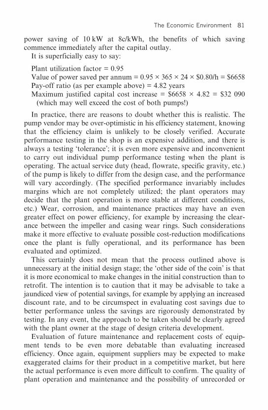
The Economic Environment 81
power saving of 10 kW at 8c/kWh, the benefits of which savingcommence immediately after the capital outlay.
It is superficially easy to say:
Plant utilization factor = 0.95Value of power saved per annum = 0.95 × 365 × 24 × $0.80/h = $6658Pay-off ratio (as per example above) = 4.82 yearsMaximum justified capital cost increase = $6658 × 4.82 = $32 090
(which may well exceed the cost of both pumps!)
In practice, there are reasons to doubt whether this is realistic. Thepump vendor may be over-optimistic in his efficiency statement, knowingthat the efficiency claim is unlikely to be closely verified. Accurateperformance testing in the shop is an expensive addition, and there isalways a testing ‘tolerance’; it is even more expensive and inconvenientto carry out individual pump performance testing when the plant isoperating. The actual service duty (head, flowrate, specific gravity, etc.)of the pump is likely to differ from the design case, and the performancewill vary accordingly. (The specified performance invariably includesmargins which are not completely utilized; the plant operators maydecide that the plant operation is more stable at different conditions,etc.) Wear, corrosion, and maintenance practices may have an evengreater effect on power efficiency, for example by increasing the clear-ance between the impeller and casing wear rings. Such considerationsmake it more effective to evaluate possible cost-reduction modificationsonce the plant is fully operational, and its performance has beenevaluated and optimized.
This certainly does not mean that the process outlined above isunnecessary at the initial design stage; the ‘other side of the coin’ is thatit is more economical to make changes in the initial construction than toretrofit. The intention is to caution that it may be advisable to take ajaundiced view of potential savings, for example by applying an increaseddiscount rate, and to be circumspect in evaluating cost savings due tobetter performance unless the savings are rigorously demonstrated bytesting. In any event, the approach to be taken should be clearly agreedwith the plant owner at the stage of design criteria development.
Evaluation of future maintenance and replacement costs of equip-ment tends to be even more debatable than evaluating increasedefficiency. Once again, equipment suppliers may be expected to makeexaggerated claims for their product in a competitive market, but herethe actual performance is even more difficult to confirm. The quality ofplant operation and maintenance and the possibility of unrecorded or

82 Handbook for Process Plant Project Engineers
undetected abuse, as well as deviations between specified and actualoperation, make it rather difficult to apportion responsibility forequipment maintenance costs and indeed failure, over the longer term.It is too easy for the equipment supplier to blame the operationalenvironment for poor performance, and it is no wonder that equipmentis usually purchased on a 1-year guarantee period, even though the lifeexpectancy may be 15 years. Consequently, it is more normal to specifyequipment features which should result in increased reliability andlonger life, rather than leave the emergence of such features to thecompetitive purchasing process. In fact, the nature of a process plant issuch that potential causes of accelerated failure and high maintenancesimply cannot be tolerated. It is customary in the equipment selectionprocess simply to eliminate options which are less desirable on thesegrounds rather than try to evaluate the cost–benefit trade-off.
Not that the maintenance costs can simply be overlooked in equipmentselection. In particular, the cost of spare parts, and as far as practicablethe equipment supplier’s policy and reputation in regard to spares andmaintenance costs, need to be considered. Several manufacturers aim tomake all their profit on spares and none on the original equipment.
For study purposes, it is of course necessary to estimate plant mainte-nance and periodic component replacement costs for the overall planteconomic evaluation. This is usually made on a basis of experience ofsimilar plant and environments, for example 4 per cent of total plantcapital cost per year. Estimates made on the basis of detailed build-upare inclined to be too optimistic and not worth the trouble of theexercise. This may not be the case for single pieces of large equipment,or plant which is centred on relatively few major equipment packages,as for power generation.
Decommissioning costs may also be a factor to be considered ineconomic evaluation, but deferred cash flow discounting usually greatlyreduces the significance. An exception may be plants which createlasting pollution, but such plants are increasingly unlikely to be licensedfor operation in the first place.
8.3 The real world of costs and values
We touched above on the impact of fiscal authorities and capital sourceson the economic trade-off which determines the optimum choice ofmany plant design features. Their impact is such that they are worthy offurther elaboration.

The Economic Environment 83
Taxation rules that affect plant finance are many. The most importantfactor is usually the treatment of depreciation, which is frequently usedas an investment incentive by allowing the capital cost to be written offagainst operating costs over an unrealistically short period, for example3 years (notwithstanding that maintenance policies are usually tomaintain or enhance plant value in the first years of operation). Theeffect of this is to make capital cheaper, by an amount which dependson the discounted value of the tax saving.5 On the other hand, theremay be a tax ‘holiday’ over the period of initial operation, effectivelynullifying the benefits of depreciation. The taxation treatment of itemsof operating expense and revenue may likewise have an effect on theoptimum plant configuration and design.
Low-interest finance packages, such as export incentives, may alsohave a major effect on the cost of capital, and influence the design moredirectly by restricting the sources of supply. Thus in the real world,it is usually necessary to work out each year’s cash flow in detail, andto apply actual taxation and item-specific capital interest, to reach thecorrect trade-off for individual item design optimization. Failure toascertain the real impact of the fiscal and investment environment canlead to quite uncompetitive designs.
There are some factors that affect the capital/operating cost dynamicswhich are best left to the plant owner. One is the assessment of uninsur-able risk, related to the possible effects of changes of cost inflation andchanges of the market for the plant’s product. The second is that in thewider field of the client’s operations, especially for global companies, itmay be expeditious to incur apparently sub-optimal costs and profits atisolated parts of the overall operation, in order to centralize profits inone place rather than another, and thereby make significant tax gains.
However, if the correct attention and consultation is given at theoutset of the project or study, it is usually possible to arrive at a simpleset of rules, expressed in pay-off time, that makes financial analysisrelatively simple. (The reservations expressed above on the credibility ofcertain technical aspects of the analysis remain.)
8.4 Project engineering and management workFor the economic analysis of engineering and management work, it isfirst necessary to recall the observations made in Chapter 5, The
5 There is occasionally a sting in the tail here; if the plant performs subnormally in itsinitial years, there may be no profits on which to reduce the tax.

84 Handbook for Process Plant Project Engineers
Project’s Industrial Environment. In particular, that the work of theproject engineering and management team (costed as indirect fieldcosts or IFCs) may be segregated into a core of essential activities and avariable amount of work which can only be justified if the benefits ofthe work exceed the costs.
Much engineering work is an iterative process, in which designsare conceptualized, developed and presented in a comprehensibleformat such as a drawing or model, reviewed, and then re-worked untilapproved. There is no inherent limit to the number of iterations ofreview and re-work. As projects become larger and more complex,with the participation of a greater number of disciplines carrying outinterrelated activities, the need for correspondingly more review andconsequential re-work becomes apparent. Failure to do so results inconstruction clashes, interface errors, and equipment accessibilityproblems. The costs of review may be reflected in additional manhours,or in additional activities of physical and computer modelling, processsimulation and testing, and also in the cost of schedule delays whileadditional engineering work is done as a consequence of the review.
By economic consideration, the optimum amount of review andre-work, and hence the optimum amount of engineering, has beenperformed when a trade-off is reached between the benefit of review andthe associated costs. The benefit, for this purpose, is the added value interms of improved plant design and reduced construction cost withreduced error rectification.
The trade-off analysis can be expressed formally by the standardelementary economic theory of diminishing returns. It is illustratedin Fig 8.1 which shows the curve of direct field cost (DFC) againstengineering cost (EC). ‘Diminishing returns’ says that the curvehas a negative slope which is constantly increasing, asymptotically,to zero slope. The line of engineering cost against engineering costis obviously a straight line with slope +1; adding the two curvesyields the total cost (TC) of the engineered plant. By inspectionor by differentiation, there is a minimum total cost when the rateof increase of DFC with respect to engineering cost is equal to –1, inother words, the incremental cost of engineering equals the associateddecrease of DFC.
Care needs to be exercised when making historical comparisons of theengineering costs of projects on what was the engineering workscope onthe job in question. As we have previously seen, the engineering andmanagement scope can be shifted between the project engineering team,the equipment suppliers, the fabrication and construction contractors,

The Economic Environment 85
outside consultants, and the plant owner’s team. More specific examplesof this practice include:
• the purchase of integrated packages of equipment rather thanindividual items;
• omission of drawings, such as piping isometrics or as-builts, whichbecome the responsibility of the fabricator;
• using lump-sum rather than per-item contracts for construction;• imposing field measurement checking responsibility on the contractor;
and• reducing office checks.
The list above is potentially endless. The same overall engineeringwork is done, but the work is shifted to the direct field cost report.
Extra engineering work can be created by imposition of exacting designand documentation standards, and reduced by the acceptance of previous
Fig. 8.1 Optimization of engineering inputs(The same logic applies to all management inputs)

86 Handbook for Process Plant Project Engineers
project or standard designs. Procurement policies can have a majoreffect on the engineering work required for an order. The engineeringwork of construction support, manufacturing follow-up, and commis-sioning activities can be defined and reported in different ways, all ofwhich will impact on the perceived engineering workscope.
Work can also be shifted between the study which precedes theproject and the project itself. The owner/investor can decide as a matterof principle that the design basis produced for the study is frozen at theoutset of the project, or that it must be re-worked completely as part ofthe project work.
It should be noted that the various ways of carrying out the project,and their impact on apparent engineering costs, are not just craftydevices for reducing or increasing engineering costs (although that maybe the intention!). The best option may be different on different projectsor for different contractors. There is no golden rule as to what is optimal.
Assessing engineering work as a percentage of plant capital cost canbe misleading in other ways. If the design capacity of a plant is doubled,without any change to the complexity,6 there may be little or no changeto the quantity of engineering work – the same number of documentshave to be produced, with the same number of information items. Butthe capital cost of the plant can be expected to increase by a ratio ofsomething like 22/3 (or 60 per cent). On this basis, the curve of engineering-cost/plant-cost ratio versus plant capacity will feature a continuouslydecreasing ratio as capacity increases. However, the concept of such acurve is more likely to be misleading in practice, because the process oftrade-off (if allowed to take place) will dictate that extra engineeringactivities are economically justifiable on the larger plant. It is worthspending more time making improvements.
In conclusion, it can be very misleading to set standards or drawstatistical comparisons on what should be the ‘correct’ number ofmanhours or engineering cost for a given project. There can of course belarge differences in performance between different engineering teams.Engineering performance is affected not just by the manhour input,but also by all the usual factors of skill, training, effort, use of advancedsystems and software, availability of previous usable designs, and goodmanagement. One would expect a good return from better engineering,and arguably this can only be gauged from an expert assessment of howthe work is done in relation to the challenges of a particular project,rather than by drawing up statistics on cost percentages.
6 Complexity is usually assessed by the number of mechanical equipment items.

The Economic Environment 87
The general observation about increased engineering work providingdiminishing returns, and thus leading to an optimum at which the overallproject costs are minimized, is in fact general to all project managementactivities. There is an optimum value for the intensity of each activity atwhich the marginal cost benefits become less than the cost of the input.As the way in which each cost element responds to management inputvaries according to the circumstances of each project, and can evenchange from day to day (for example, as extra project management andengineering input are needed to solve supply problems), there is clearlyno unique overall optimum value – ‘the right cost for project manage-ment for this type of project’ – except perhaps in cloud-cuckoo-land.

This page intentionally left blank

Studies and Proposals 89
Third Cycle
Conceptual Development

This page intentionally left blank

Studies and Proposals 91
Chapter 9
Studies and Proposals
9.1 Feasibility studies
In the preceding brief overview of project management, we chose toaddress the workings of a project as a task with defined goals and adefined and accepted concept for achieving them, with only the mostcursory mention of the work necessary to get to that point, referred toas ‘the study’. Now we will address the means of getting to that point.There are a few reasons for moving in this apparently bizarre fashion.The ultimate objective of the study is the project, and it is easier tocomprehend many of the study activities if we start by understandingthe objective. Much (but not all) of the work executed in the study is infact an abbreviation of the more detailed work carried out at the projectstage, when physical commitments are produced rather than paperabstractions; it is difficult to properly describe an abbreviation withoutfirst describing the full process. Competent study practitioners have firstto become competent project practitioners, although the full learningexperience seems to be a number of cycles of both.
We will begin from the point when a management or an investortakes a decision to expend resources to examine the business potential ofan idea, in other words, commissions a study. This is at any rate thestarting point for the purposes of this book; it would be possible todigress at great length on both technical and business research processesleading up to the production of worthwhile ideas.
The study invariably includes the following.
1. Defining the idea.2. Developing the process application of the idea. The work to be done
obviously depends on what has gone before. It may be necessary to

92 Handbook for Process Plant Project Engineers
commence with laboratory research and bench-scale testing ofprocesses, and with geological exploration and widespread samplingof raw materials. Proving the reserves of acceptable plant feedstockis often a major part of a study, but it is not addressed here becauseour interest is in the process plant. In general, it is necessary to obtain sufficient data on the materialsto be processed, consider the available process options, carry outany process testwork that may be required to demonstrate workableprocess routes, and prepare flowsheets based on the applicableprocesses.
3. Evaluating the process proposals technically and economically. Thetechnical evaluation may involve further testwork, and possibly theconstruction of a pilot plant. It may be possible to observe similarexisting plants, where the performance of the process can bedemonstrated under industrial conditions. The economic evaluationimplies estimating the capital and operating costs of the plant, andfor this it is necessary to prepare at least an outline design of theplant. The economic evaluation may also involve product marketingsurveys and similar activities beyond our scope.
4. Reviewing, testing, redesigning, optimizing, and re-evaluating thevarious possibilities; selection of the most attractive proposals,and presentation of the corresponding technical and economicevaluation.
Usually before a project goes ahead, investors demand a level ofconfidence in its technical and economic viability, in keeping with thevalue of the investment. Before a major project is authorized, it is notunusual to go through years of technology search and negotiation,laboratory and pilot plant tests, plant design and costing exercises,hazard and risk analysis, environmental impact studies, market studies,and financial analysis. There may also be negotiations with statutoryand government bodies, trades unions, buyers of the product, and otherinterested parties.
As our focus is on project engineering, we will direct our attentionto those parts of the study with which the project engineer is mostconcerned, beginning with the evaluation of the process and the processdesign information. Firstly we need to know that we have a processwhich works, and can be operated in an industrial environment. For allbut the simplest processes there are only two ways to do this: preferably,by ensuring similarity to existing successfully operating plants, or failingthat, by operation of a pilot plant. The challenge here lies in the

Studies and Proposals 93
word ‘similar’. To know what constitutes similarity, and to be able torecognize any small difference which may have a critical effect, requiresan expert knowledge of the process in question. Thus it is necessaryto have both reference and/or pilot plants and an expert opinion ontheir relevance to assume any level of confidence in an applicationof process technology.
To design a plant, which can be expected to work as well as theexisting plants on which the design is based, usually requires anunderstanding of several special engineering features which may not bereadily apparent. Such features may include, say, special materials ofconstruction, small equipment-design changes, and specific maintenancefeatures, which are the product of the process development, oftenarrived at through expensive trial and error. We need to have theleading participation of the process technologist in the development ofthe full plant design criteria.
The development of appropriate process flowsheets and basic processengineering is also outside the scope of this book. We will begin at thepoint of developing the process designs into actual plant designs, whichcan be assessed technically and costed. In principle, the work that hasto be done is the same as the initial work already described for theengineering of projects:
• comprehensive design criteria are prepared;• process equipment bids are solicited;• equipment selections are made for purposes of plant design and costing,
but without any commitment;• plant layouts are developed in conjunction with appropriate materials
transport system design; and• structures, civil works, electrical and instrumentation systems,
piping, and any other utilities and facilities are designed and costed.
However, unlike project work, studies are usually commencedwithout a definite plant design concept and construction plan; these aresubject to change, and the essential requirement is to find the mostsuitable concepts and plans which will become the basis for the detailedproject designs, budgets, and schedules. Inevitably the plant design isdeveloped in a series of iterations. Initially, relatively broad concepts areexplored, and possible innovations are introduced. Some concepts, forexample materials handling system, layout, or site location, may bequickly rejected, while others may need more detailed comparison toarrive at the best choice. The phases of initial conceptual development,and of more detailed design and evaluation, are often formally split into

94 Handbook for Process Plant Project Engineers
two parts: a pre-feasibility study with an accuracy1 of say ±20 per cent,and a feasibility study with an accuracy of say ±10 per cent. This givesthe investor an opportunity to abort the study work or change directionbefore too much money is spent.
The development of cost-effective designs is discussed in Chapter 11,Value Engineering and Plant Optimization. Cost estimating is clearly atthe heart of study work; it is one of the investor’s main concerns. Inkeeping with the need to carry out initial study work comparativelyquickly and less accurately, there are a variety of estimating techniquesavailable to estimate plant costs without doing too much design work.Ultimately, however, an accurate estimate must be based on the submis-sion of competitive bids for all items, and the bids must be based on theadequate specification of equipment items, and adequate quantificationof sufficiently developed designs of other items.
9.2 Proposals
Studies may be regarded as a type of proposal, in that they relate to theproposed construction of a process plant. However, we will restrict theuse of the term ‘proposal’ to that of an offer, namely an offer to build aspecified process plant at a certain price or price basis, a commitmentrather than an estimate. ‘Study’ will be used when an estimate of plantcosts, rather than a commitment, is submitted. The essential content ofa process plant project engineer’s work is the same for both, but there isa fundamental difference in how the end product is used, in that therelationship with the client is different. There is a correspondingdifference in the assessment of risk.
9.3 Estimating project costs
Certain cost estimating techniques are relevant to pre-feasibility studiesonly, and will therefore be addressed first. There are various techniquesfor making rough or preliminary estimates of plant cost which areparticularly useful for pre-feasibility studies. The most elementary of
1 ‘Accuracy’ is a word which is customarily used in this context, but the understandingof what is meant varies quite widely; in fact the word is often used without anyunderstanding of its implications, such that the value of the quoted accuracy ismeaningless. The suggested usage is discussed in Section 9.3.

Studies and Proposals 95
these is the ‘curve price’, in which the entire plant cost is interpolated orextrapolated from data on previous projects to construct similar plant,the ‘curve’ in question being a graph of plant cost against capacity. Dueto limitations on similarity, it is seldom possible to assign an accuracy ofbetter than ±30 per cent to such an estimate.
The more developed techniques for preliminary estimates are basedon factorization. The basis for factorization is the observation that thecosts of component parts of process plants bear similar ratios to eachother in different plants.
Consider for instance the breakdown of the plant capital cost into thefollowing (all components include the associated site construction andpainting costs):
• civil works• structural steelwork• mechanical equipment• electrical equipment and reticulation• instrumentation and control gear• piping• transport to site• indirect costs (engineering and management, insurance, etc.).
This breakdown includes all elements of the plant, that is to say thatpossible other elements of breakdown (such as platework and valves)are included in the above headings (for example mechanical equipmentand piping respectively).
Now the largest of these components is invariably the mechanicalequipment, and it is also the most fundamental component, beingarrived at directly from the process flowsheets and process requirements.The other plant items follow from the mechanical equipment needs. Soin the simplest factorization technique, the plant cost is factorized fromthe mechanical equipment cost, which is generally in the range of 30–45per cent of the direct field cost, or 25–40 per cent of total cost, includingindirects.
There are many possibilities for improving the accuracy by designingand estimating more of the other plant components, and factorizingonly the most intractable, say piping. The technique is also refinedby developing ratios of plant costs corresponding to each typeof mechanical equipment, for example the ratio of the cost of acentrifugal pump to the cost of the associated civils, structurals, piping,electrical, and instrumentation. An appropriate factor is developedfor each mechanical equipment type; the plant cost is the sum of

96 Handbook for Process Plant Project Engineers
the individual mechanical equipment costs, each augmented in itsappropriate ratio.
It will be evident that the accuracy of factorization techniquesdepends on the similarity of the type of plant, and also the consistentgrouping of cost elements into the factorized components. A plantwhich is intensive in bulk solids handling is not comparable to an oilrefinery. If the cost database is inconsistent as to whether, say, thermalinsulation costs are included under piping on one project and undermechanical equipment on another, accuracy will be reduced. Whenthere is a reasonably consistent database of reasonably similar plant,factorization of the mechanical equipment total may yield an estimatefor which an accuracy of ±25 per cent can be claimed. This could benarrowed to say ±20 per cent if the more advanced factorizationtechniques are used, but hardly better unless there is extreme confidencein a recent database of very similar plant.
For most clients and circumstances, the level of confidence required,before the project is authorized, dictates that the plant is designed andcosted in detail. Therefore factorization-estimating methods are usuallyrestricted to pre-feasibility work or comparison of plant alternatives.
‘Costed’ means that costs are estimated in a way that should correspondto the agreements that will eventually be struck with suppliers andcontractors when the project goes ahead. The most obvious way to arriveat such prices is to solicit bids based on appropriate specifications, andto review the bids technically and commercially as carefully as for anactual project.
The knowledge that costs are based on actual bid prices is oneof the principal sources of confidence in the estimate. However,there are limitations to this practice. Suppliers may object to beingused in this fashion, when no immediate or perhaps any potentialbusiness can arise from their effort, so they may decline to bid orsubmit uncompetitive offers. The work of specification, enquirypreparation, and bid analysis may overload the study/proposalbudget and time schedule. Cost-estimation techniques, databases, andexperienced judgement are therefore essential supplements to directmarket information.
Apart from the need for job estimates, individual engineeringdisciplines have to develop and maintain current databases and methodsfor costing plant design alternatives in order to select the best designs.This process has to be carried out so frequently and rapidly that it is notpracticable to be wholly dependent on solicitation of market priceswhenever data are required. In fact, an engineering organization where
Studies and Proposals 97
the individual engineers have little relevant cost data or cost-estimationtechniques is invariably not a cost-conscious organization, but rather anuncompetitive monolith.
It is clear therefore that a good knowledge of cost-estimating tech-niques, and maintenance of a relevant database, are an essential part ofthe project engineer’s armoury. There is no lack of publications on thesubject; for instance, the guide produced by the Institution of ChemicalEngineers and the Association of Cost Engineers is a useful introduction.2
However, at the overall project or organizational level, there is nosubstitute for the employment of experienced professionals for thisfunction.
9.4 Risk
The engineering and estimating work of a study or proposal is notcomplete until its accuracy has been established. For pre-feasibility-typework, where the level of commitment is relatively low � at most leadingto a decision to finance a full feasibility study � it is usually consideredacceptable to presume an accuracy based on experience; that is, basedon previous validated experience that enough design and costing workhas been done to justify the accuracy quoted, which is unlikely to bebetter than ±20 per cent. It is also expected that any significantuncertainties and hazards will be summarised in the pre-feasibility studyreport, for detailed attention during the feasibility study.
However, when a firm commitment to build a plant is under consid-eration, detailed assessment is normally required of all cost elementsand of everything that can go wrong and affect the viability of theproposed commitment. The process is described as risk analysis. Manytreatises and methodologies are available, as befits the gravity of asubject which can seriously affect the fortunes of major enterprises. Wewill address the fundamental aspects.
A risk is defined as a possibility that a project outcome may differfrom the planned outcome.3 Risk can be quantified as a probability. The
2 Institution of Chemical Engineers and Association of Cost Engineers (UK): Guide toCapital Cost Estimating, 2001.
3 There are other definitions, for example ‘the likelihood that an accident or damage willoccur’, which is more appropriate in a safety context. In the commercial context, thereis also risk of a better outcome (lower price, better performance), which must beconsidered in quantitative decision-making.

98 Handbook for Process Plant Project Engineers
principal project outcome is financial, and the consequences of manyother unsatisfactory outcomes � late completion, unreliable operation,unsatisfactory process performance � can be expressed in financialterms, either as cost of rectification or reduction of plant profitability.Some possible outcomes may be unacceptable in their consequences,and it will be necessary to take action to avoid, manage, and mitigatethe risks.
The first step in the process is risk identification, which is accom-plished by review of the proposal/study by suitably experienced expertsusing well-considered checklists. These must embrace all facets whichmay affect the project outcome, such as plant feedstock quality, processreliability, mechanical reliability, potential foundation problems, opera-tional hazards, environmental impact, equipment costs, constructioncosting and labour, statutory requirements, contractual and legalproblems peculiar to the country of construction, eventual decommis-sioning costs, and so on. Risks due to operational hazard are generallytreated separately from commercial risk, and will be discussed in Chapter12, but they are obviously an essential part of the overall process.
As risks are identified, the potential impact is assessed, and if consideredsignificant, risk management action is decided. This could be the com-missioning of additional testwork, hiring of appropriate experts, sharingof risks by contractual arrangement, introduction of more conservativedesigns, taking out of insurance � there are usually many possibilities.Most risk management actions simply become another project activity,with an additional cost component in the proposed project budget.
Quite apart from the significant identified risks, there is always thepossibility of unidentified risk, and there is always a risk that individualcost components within the project cost estimate may eventually proveto be incorrect. Design development, inflation, changes in the suppliers’marketplace, and the difficulty in making firm supply and sub-contractcommitments at the time of estimating mean that most items have to berepriced at the project stage. This is not a one-way process; often there ismore intense competition, and lower prices are available. These pricinguncertainties, and the variation of possible cost impacts arising out ofthe risk assessment, have to be addressed by experienced judgement(possibly aided by statistical analysis) to arrive at an appropriatecontingency; this is discussed in Section 9 below.
At the conclusion of the process there will be a report on risksidentified, potential impact, management action considered to be appro-priate, and an evaluation of whether the acceptance of the managed riskis considered to be ‘reasonable’. This is about as far as the risk analysis

Studies and Proposals 99
and management process can go, unless there is an overall statutory orcorporate dictum that certain risks are not considered to be tolerable.Ultimately, a risk-taking executive, body, or board has to make aninformed decision on whether to accept the risk, in the light of therewards for adopting it or the cost of the opportunities lost.
As a final note, project engineers need to bear in mind that a legal riskis inherent in any of their work. The more obvious obligations toexercise reasonable care and diligence in producing designs which aresafe to build and operate probably require no emphasis. However, inmaking a recommendation to an investor (even indirectly), there is anobligation to exercise care and diligence, which can attract very substan-tial civil liability. Depending on the country of investment, and possiblyany other countries in which investors may be affected, the obligationsmay be quite unreasonable in relationship to the engineer’s fee andscope of work. Legal advice, qualification of responsibility, limitationof liability, and insurance should be considered before making anycommitment or submitting a report.
9.5 Accuracy
The ‘accuracy’ of an estimate is a widely misused and misunderstoodterm. Mathematically, accuracy can be expressed by the limits ofa range of values within which the correct figure lies. If the only possiblesolutions to a problem lie within the range 6–8, then the answermay be expressed as 7 ± 1. However, life is not so simple for the plantcost-estimator. His estimate is made up of a large number of costelements, none of which is certain, even as to the absolute limit of therange of possible cost. There is no certainty in his life, only probabilityand confidence. Certainty only exists when the project is over!
In fact, the estimate can best be presented as a probability curve, aplot of estimated cost (x-axis) against the probability that the actualcost will fall within a defined band (say ±2 per cent) of the estimatedcost (y-axis), which is shown in Fig. 9.1. The curve will clearly feature amaximum value at the most probable cost, or the cost considered to bemost probable, and slope downwards on each side of the maximum.That is about all that is known about the shape of the curve. Manymodels (normal, skewed, Poisson, geometric distribution, etc.) areassumed and used in practice.
Because it is a probability curve, sloping away on each side todiminishing but never-zero values, it is only possible to assign limits

100 Handbook for Process Plant Project Engineers
of accuracy in association with defined probability or confidencelevels. Thus to claim a plant cost estimate is accurate to ±10 per centis meaningless in itself, unless a confidence level is assigned to the limits.It is, for instance, meaningful to claim that the estimate is accurate to±10 per cent with 90 per cent confidence that the estimate will fall withinthese limits, or to quote a maximum value of plant cost which theestimator has 90 per cent (or 95 per cent, or whatever) confidence of notbeing exceeded.
Simply considering the shape of any probability curve makes it clearthat different limits of accuracy are applicable for different confidencelevels. And yet investors (clients) do persist in demanding that estimates(and therefore all the work of a study) be carried out to specified levelsof accuracy without specified confidence levels.
Except for pre-feasibility work, the engineer is advised to submithis estimate with stated confidence levels corresponding to the statedaccuracy limits, based on at least a rudimentary statistical analysis ofelement cost variation.4 If project costs eventually fall outside the
Fig. 9.1 Plant cost probability
4 There are standard and easily applied software packages available, for example @Risk.

Studies and Proposals 101
quoted limits, he can at least be justified in saying: ‘Oh well, that wasthe 5 per cent possibility’!5
9.6 Contingency
Here is another loosely used term. A recommended definition ofcontingency, which comes from the American Association of CostEngineers, is:
A cost element of an estimate to cover a statistical probability of theoccurrence of unforeseeable elements of cost within the defined projectscope due to a combination of uncertainties, intangibles, and unfore-seen/highly unlikely occurrences of future events, based on managementdecision to assume certain risks (for the occurrence of those events).
This definition is rather a mouthful, and needs to be thought outquite carefully. It may be easier to visualize in terms of the probabilitycurve mentioned above. A contingency is an amount to be added to theestimated cost (assumed here to be the most probable cost, correspondingto the top of the curve, but not necessarily so) to increase the confidencelevel to an acceptable probability (say 90 per cent) of a cost that will notbe exceeded. In this definition, it is implied that a project has a fixedscope, and any elements of approved scope change will be handled asapproved variations to the project budget.
This definition is not the universal usage of the word. In some quarters,the ‘contingency’ is an amount included in the authorized projectbudget to allow for any variations in scope or any lack of forethought(or whatever) to ensure that the project budget is not exceeded; practi-cally, a margin for error and for future changes � extra money in thebank. This concept has in the past been taken to an extreme in certainplush institutions, where quite large contingencies, even up to 20 percent, were routinely included in the budget of an authorized project bythe executive responsible. This contingency was not passed on to thenext level of authority � say the poor old project manager � thus it waspossible for the lower level to produce a mediocre performance in termsof budget, while the upper level was a star. This is nice work if you canget it � at the upper level!
5 OK, that is the second thing he will say, after the inevitable condemnation of theproject manager!

102 Handbook for Process Plant Project Engineers
The extreme example quoted is reflected to some extent in generalbehaviour. All project managers (and other performers) like to havesome extra contingency, often hidden in various innocent-lookingexpenditure items. Clients and managements are wise to this, and try toeliminate such items from the budget or reduce their value, and as aresult the person immediately lower down in the hierarchy finds itharder to demonstrate adequate performance. This is a valid andnecessary aspect of management, of promoting efficiency, but theperson ‘one down in the heap’ is well advised to be on the look-out forabuse, the most frequent form of which is a sloppy and potentiallyone-sided definition of contingency. Most frequently, one-sidedpractitioners of unreasonable estimate reduction wish to:
• remove from the estimate items which are likely to be needed but arenot yet properly defined, and seek to cover these items by minimalallowances labelled as contingency.
• exclude from the contingency any allowance required (by statisticalanalysis or ‘gut feeling’), to change a 50 per cent probability to (say)a 90 per cent probability.6
Ultimately, this is a game which is as old as projects, and the projectperformers have to understand at each level whether they are in agame-playing relationship, and if so how to play it. There are no rules tothe game but there is a basic rule for survival of the project performerwhose contingency is under attack, which is to avoid sloppy definitionof cost components. He should carefully identify all foreseeable costcomponents and allot appropriate individual allowances, and avoidrolling any such allowances into the contingency. This should bereserved and maintained for unforeseen risks, and for decreasing theprobability of overrunning the budget, by increasing confidence levels ina statistically defensible fashion. Such a contingency may be determinedby evaluating the possible variation of cost for each component of theestimate, and performing a statistical analysis as outlined in Section 9.5,Accuracy.
As a rule of thumb, to arrive at an estimate which has 90–95 percent probability of not being exceeded, a contingency of 1.5 times the
6 Contingency calculation and management are often an exercise of power, rather thanmathematics. Some executives use the above techniques to eliminate all real contingency,and then indulge in further power-play by requiring special authorization to access eventhis bogus contingency.

Studies and Proposals 103
standard deviation should be added. A standard deviation of about 3per cent should be achievable for a good estimate, based on:
• well-developed P&I diagrams;• properly reviewed plant layouts;• comprehensive equipment data;• conceptual designs for each discipline;• individual discipline quantity take-off, including adequate growth
allowances; and• competitive pricing of at least 90 per cent of the cost items by value.
So 4–5 per cent contingency would be required to establish a figurewhich has a 90–95 per cent confidence level of not being exceeded.
We must emphasize again that this contingency is applicable to aproject having exactly defined overall scope. As scope variation isfrequently required after project authorization, organizations investingin process plant seldom admit that a plant cost can be evaluated tomuch better than limits of ±10 per cent until the project is well underway and all designs have been frozen. Put another way, a contingencyevaluated as above may be appropriate for a contracting companywhich is committing to a fixed price for the plant, but the client’s projectmanager probably needs a contingency of another 5 per cent or so toallow for scope variations.

This page intentionally left blank

Plant Layout and Modelling 105
Chapter 10
Plant Layout and Modelling
10.1 Layout
Plant layout is the fundamental conceptual design activity which followson from the definition of the process and the mechanical equipment. Itwas noted in the previous chapter, in Section 9.3, Estimating projectcosts, that a preliminary plant cost could be factorized from mechanicalequipment costs with an accuracy expectation of ±25 per cent. Anyincreased accuracy of costing depends primarily on determination of theplant layout. Of course this may not have to be designed specifically;but the applicability of similar plant layout designs, at least, needs to bedecided. The relevance of quoting the order of magnitude of costingconfidence is that it gives some idea of the influence of layout design onplant cost.
Following on from the flowsheet, which determines the mechanicalequipment requirements, the layout reflects and determines most otherplant cost components, and its optimization is obviously critical to thedevelopment of a cost-effective plant. It is equally critical to thedevelopment of a functional and maintainable plant that is safe andergonomically acceptable, and can profoundly affect operating costs.
The terminology we are using is that, as was described in the basicsequence planning of engineering work, ‘layout’ drawings are thosewhich are produced prior to the stage of receiving final equipmentdetails and structural design. The layouts therefore include overall orcritical dimensions only, whereas the final ‘general arrangements’ arethose used for controlling and verifying plant construction details.Layouts are intermediate, not construction, drawings. This terminologyis not uniformly adopted in the process industry.
Layouts are developed by review and progressive refinement, oftenconsidering many alternatives as befits their importance. There is no

106 Handbook for Process Plant Project Engineers
limit to the number of iterations which may be demanded, so theamount of work to be carried out is often the subject of argument,especially by a demanding client who is paying a lump sum for thework. Layout development belongs squarely in the conceptual phase ofthe project (or study). If the layouts are not frozen, the project budgetand schedule cannot be considered to be final, though obviously there issome scope for debate on what ‘frozen’ means and what level of detail isincluded in the freeze.
It is obviously critical that final (frozen) layouts are able to accommo-date any variations in equipment size, piping design, etc. that maybe required by final detail design. Otherwise there may be at least amajor disruption to the design process and schedule while the layout isadjusted, or an unwanted compromise (it may be described moreharshly!) in the final plant configuration.
In practice, plant layout development is dependent on experienceand design insight, and there is no substitute for having the mostexperienced practitioners for the job. The following outline is aimed atrecognizing the information necessary to advance the layout work, andat reviewing the end result.
Important factors affecting the layout are included within the overalldesign criteria, including the process design criteria, Appendix 2; theprime importance of these requirements should not be forgotten, evenwhere they are not further elaborated here. The three fundamentalconsiderations of layout are the mechanical equipment, the materialstransport systems, and the plant structures, which are mainly designedto suit the first two.
Layout considerations arising from the mechanical equipment, anddependent on the design and operation of the equipment, include thefollowing.
• The method of feeding the equipment and removing product(particularly important for bulk solids processors).
• Equipment access requirements for operation and routine maintenance:� starting and stopping� observation of operation and of local instruments� product inspection and sampling� equipment inspection and adjustment� lubrication and cleaning� catalyst or internals replacement� emptying, draining, flushing, venting, making ready for
maintenance.

Plant Layout and Modelling 107
• The means of spillage removal (mainly for plants handling bulk solids).• Facilities and access for major maintenance, including equipment
removal and replacement. These may include permanently installedlifting devices (cranes, hoists, lifting beams, trolleys, etc.) and thesuitable configuration of surrounding plant and structures, forexample the provision of removable floor and roof sections, andadditional flanged connections in surrounding ducts.1
• Clearances and special requirements for operational hazards,fire-fighting, and safety requirements.
• Unusual static and dynamic loads, and consequent structuralsupport requirements or isolation of vibrations.
• Noise attenuation.• Any other requirements or advice from proprietary equipment
manufacturers, where applicable. (They should be a prime source ofinformation, comment, and eventual approval, although unfortunatelythey cannot always be relied on to have good representation.)
It is necessary to check through the above list, at the very least, toensure that a proposed layout is appropriate for each piece of equipment.
In processes where materials are transported mainly in the fluidphase, such as most oil refinery units, the piping design considerationstend to dictate the layout, whereas for plants processing solids, such asmetallurgical reduction plants, the bulk solids handling design is themajor consideration.
The engineering of fluid handling systems, including piping andducting, and their influence on layout, is addressed in Chapter 14.Piping considerations at the layout stage include not only the routing(without creating plant access problems) but also support of the pipes,access to valves, and provision for major expansion loops. Ducting,particularly large diameter duct systems tied into a common stack, canhave a crucial influence on layout.
Bulk solids handling is addressed in Chapter 15. Some considerationalso needs to be given to the intermediate case of two-phase flow andespecially slurry transportation, and this is described in Chapter 16.Bulk solids handling is inherently more complex and less flexible thanfluids handling, and has a correspondingly greater impact on layoutoptions. Conceptual engineering of the conveyors and gravity flow
1 It is easy to go too far with this, for example spending money on bolted connections,which will hardly be used in practice (the ‘Meccano mentality’), when cutting and weldingmay be acceptable.

108 Handbook for Process Plant Project Engineers
systems (and their elevations) is an inseparable part of layout develop-ment, whereas for fluid flow systems there is more scope for employingstandardized and modular designs.
The first plant layout operation is to understand and develop theplant arrangements around major pieces of equipment and sub-unitsof process plant, with particular attention to the shape and size of‘footprint’ and the relative positions of main interfaces, especiallypoints at which process materials enter and leave. These sub-unitsare then combined into an overall block plan development, and whenthis is acceptable the whole may be further developed into more detailedlayouts. Figures 10.1 and 10.2 are examples of finally developed blockplan and layout.
During this process, attention is given to the following.
• Reduction of materials transport routes (including those involvingmajor utilities).
• Eliminating or minimizing hazards (for example, avoid proximity offired heaters to potential sources of LPG leakage, close off areaswhere rocks may fall, and so on) and allowing adequate fire-fightingaccess.
• Ergonomics of operation, in particular, adequate operator access.• The overall site topography with respect to:
� plant feed source, including major utilities or reagents sourcewhere applicable;
� product destination;� location of any intermediate storage;� effluent disposal and drainage;� existing adjacent plant and facility interfaces;� proximity of neighbouring dwellings or places which may be
exposed to hazard or suffer nuisance from the plant operation;� the prevailing wind direction;� utilization of existing site contours to reduce materials handling
costs;� reduction of excavation and site development costs;� overall site access, and construction access and lay-down areas;� provision of appropriately positioned space for future plant
expansion.• Plant enclosure standards (roofs, walls, etc.) heating and ventilation,
and the impact of environmental conditions.• Provision and appropriate location of plant service buildings,
such as control rooms, operator facilities, laboratories, electrical
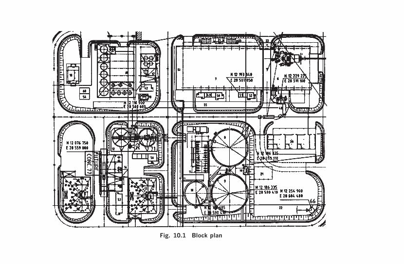
Plant Layout and
Mod
elling109Fig. 10.1 Block plan

110
Hand
book for P
rocess Plant P
roject Engineers
Fig. 10.2 Layout drawing

Plant Layout and Modelling 111
switchrooms and transformer yards, workshops, and warehouses.• Internal plant road and access design, and the overall drainage system.• Routing of piperacks and major ducts, and routing and support of
major cableracks.• Evaluating the possible impact of structural/foundation design criteria
and seismic conditions on the proximity of equipment and structures.• When required, separation of distinct process areas to facilitate shutdown
and isolation of each area for maintenance or revamp and, sometimes,to facilitate independent design and construction of those areas.2
• Site security.• Ensuring that adequate space is allowed for design changes that may
become necessary as detail design develops.• Architectural and social requirements relating to plant appearance,
and its acceptability to statutory planning authorities.
The plant layout development normally entails an iterative procedurereview and redevelopment of the individual plant area designs andfootprints until a satisfactorily balanced overall design is achieved.There may be a few major layout options to consider. Selection of thepreferred choice includes attention to:
• capital and operational cost;• overall ergonomics and safety of operation and maintenance;• constructability and possible modulization to simplify design and
construction; and• space utilization.
It is always of great assistance to visit and review the designs ofexisting reference plants, both before beginning layout work and whenreviewing conceptual layouts. Obviously, such visits are greatly en-hanced if operational and maintenance feedback is obtained.
It is vital to check and review layouts rigorously with the use of aformal checklist; the essence of such a list is included above, but this hasto be supplemented for the particular processes involved, based onprevious experience. Insufficiently comprehensive layout review hasresulted in countless cases of inferior or unacceptable plant design.
Once a layout has been approved by all disciplines (including Hazopreview where applicable) and frozen, its integrity has to be maintainedthrough the following detail design stages to prevent unauthorizedencroachment on discipline space and the compromising of access ways.
2 This subject is discussed further in Chapter 21, The Organization of Work.

112 Handbook for Process Plant Project Engineers
This is no easy task, and is exacerbated when design changes � especiallyprocess design changes � are made. The use of three-dimensional model-ling in such circumstances is strongly recommended.
Apart from individual access points, as the design develops theconnectivity of access ways must constantly be reviewed. Ensure thatthe overall system of access is convenient for plant operation, and thatthe operators and maintenance personnel are not expected to travel along way round between adjacent structures.
10.2 Design presentation and modellingBefore going on to the basic materials transport systems design and itslayout influence, it is appropriate to enlarge on item 6 (design method-ology and standardization) of the project design criteria, presented inAppendix 2, with particular reference to drafting. The objectives of‘drafting’ can be met in a number of ways, employing paper drawings,physical models, computer programs, and so on. In order to concentrateon the function rather than the method, we will employ ‘drafting’ todescribe any such process whose objectives are:
• to present a model of the plant and its components in order to facilitatethe design and its co-ordination, and to make it possible to judge theacceptability of the design;
• to record the plant design and dimensions; and• to communicate the design to third parties (that is, outside the
design team) for a variety of purposes, such as approval, purchase,construction, or repair.
In this definition, we have separated the drafting function fromthe design function, which becomes the process of deciding on theplant’s configuration, dimensions, manufacture � all its attributes. Thedraughtsman may be very offended by a supposed implication that alldesign decisions are made by others (the engineers?) when he knowsvery well that every time he puts pencil to paper (or clicks the mouse) hemakes a decision. He may even feel that his function is to design theplant, while the engineer’s function is to take the credit! So let us quicklyacknowledge that many, even most, detail design decisions are made bythe draughtsman; we are simply splitting the functions of that personinto those of design (making design decisions) and drafting (representingthose decisions).
The drafting process produces a model (a physical model, a numberof drawings, or a computer model) which aids and represents the design,

Plant Layout and Modelling 113
and a communication, which may be the model itself, the model withnotes added, drawings, or simply a set of instructions. It should benoted that the communication aspect is an important criterion ofacceptability in its own right, and has to take into account the characterand needs of the people building the plant.
In Chapter 4, in the discussion on engineering co-ordination, wehighlighted the critical importance of the plant model as the instrumentby which co-ordination in space is maintained. A model which is clearlyand quickly understood by all disciplines (and by other reviewers, suchas the client) greatly improves design quality. There is nothing to beatthe ease of visualization of a physical model, but unfortunately it is rela-tively expensive and slows down the design process. Advances made incomputer modelling in the last 30 years have taken us to the point wherethe hardware and software has become almost as economical and effectiveas the visionaries expected,3 and most design offices now utilize suchsystems. If used by adequately skilled staff, they facilitate a process ofmodel creation which matches and becomes the layout, general arrange-ment, and detail design process (see Fig. 10.3). Mutually consistentdrawings are automatically generated. There are also, of course, manyranges of design and analysis software which integrate directly to themodelling software. The trend of integrating associated design andmanagement software has continued to the point where integratedsoftware suites cover almost the entire engineering and managementdevelopment of a project.4
The further development and application of integrated computer-assisted design and drafting is the way ahead, but the choices ofmethodology to be made for a real, present-day project have to becarefully considered, in particular the need and availability of suitablyqualified staff to handle the project’s peak load requirement.
Even with the clearest model presentation, there is a need for theongoing model development to be supervised by dedicated designco-ordinators. The modelling software usually includes clash detectionand notification, but it is still necessary to ensure that in conflictsthe most important needs prevail and to maintain the integrity ofoperational and maintenance access and ergonomics. There is alsofrequently a need for ongoing independent review of the drawings oroutput communication, from the point of view of their users.
3 Unfortunately, most of the visionary users lost their shirts in the process.
4 Creating more opportunities for visionary users to lose their shirts in the process! Thesubject is discussed further in Chapter 28.

114
Hand
book for P
rocess Plant P
roject Engineers
Fig. 10.3 Virtual three-dimensioual model of plant

Plant Layout and
Mod
elling115
Fig. 10.4 Autogenous milling plant layout – showinginfluence of bulk solids handling needs

This page intentionally left blank

Value Engineering and Plant Optimization 117
Chapter 11
Value Engineering and PlantOptimization
Undoubtedly one of the most critical phases of a project or proposedproject, the part which can make it be regarded as a star or amediocrity, a winner or a loser or a non-event, is the creative phasewhen conceptual designs are developed. There are a few facets to thisphase. We have already remarked on the iterative nature of the workdone, of successive development, exposition of designs, critical review,and re-work, in search of optimal designs. It is the creative input andinnovative thinking that make this process meaningful. In the processplant field, with its heavy dependence on individual plant componentreliability, most innovation comes from the use of proven techniquesor devices in a different application, rather than the employmentof untested new devices. The leading innovators are often peoplewho have a wide knowledge of general industry practice, as wellas being innovators by nature. There is still of course room forbrainstorming and for the employment of revolutionary thinkers, butsince the latter are born rather than made, there is not much to be saidabout them here.
In the fields of management consultancy and business development,several methods have been proposed to supplement individual experi-ence and brilliance by the use of formalized techniques, whose applica-tion is not limited to process plant design. Different systems to promotecreative thinking are effective in the cultures of different organizations:each one has to find ‘what works for us’. The only general rule is thatany design organization that does not promote creative thinking in theappropriate context, is obsolescent.

118 Handbook for Process Plant Project Engineers
11.1 Value engineeringOne system of analysis topromote creative thinking, value engineering,requires special mention. It is often specifically required by clients. Wewill discuss it briefly, but this should in no way be interpreted asadequate cover of a well-developed subject with ample literature. Inits application to the design of process plants, value engineering isessentially the analysis of design by function and utility, to arrive atthe most cost-effective design. The analysis requires that a starting-point design exists. The analysis begins with the flowsheet, followed byall facets of the design and its documentation. The questions to ask ofeach item which incurs a cost or affects costs are:
• What is its function?• What does it contribute to the performance of the plant and the
project as a whole?• What minimum function and performance are actually necessary?
Are there other ways of doing this more cost-effectively?
Evidently, the questions cannot properly be answered without aninitial understanding of the plant design criteria in terms of specifiedoverall performance requirements but, aside from these, the content ofthe plant design criteria should itself be a subject for value engineeringto gain the maximum benefits.
One of the prime objectives of value engineering is the elimination ofplant features, to arrive at a design where there is ‘nothing left to takeout’. This obviously has to be tempered against a realistic view of retain-ing features required for operational contingencies and flexibilityof operation, and may make the outcome somewhat subjective andarguable, but there is no substitute for attempting to resolve such issuesby quantification. Any facility not strictly required for plant operationshould have a quantifiable value, even if the value cannot readily beexpressed in cash terms, as may be the case for some considerations ofsafety (and even this is arguable, as will be discussed in the next chapter).
By the nature of the process, it is apparent that there is no end tothe amount of value engineering that can go into a plant design, giventhat time and resources are available. An engineer who finds himselfcontracted to ‘fully value-engineer’ a plant design, within the ambit of alimited budget or schedule, may be in for a sticky time indeed.1 It is also
1 If value engineering is required within a fixed-price framework, draw up a procedure ofhow it will be done and specify what items and documents will be value-engineered, witha specimen output report.

Value Engineering and Plant Optimization 119
apparent that this process belongs firmly in the conceptual-developmentphase of a study/project, that is, before the detail design commences.
The following are examples of the application of value engineeringand the corresponding benefits.
• Combine separate plant control rooms, and save on both capitaland operational costs.
• Eliminate boilers by importing steam from another enterprise thathas a surplus.
• Modify process design requirements such that cheaper standardequipment or vessel designs can be utilized.
• Eliminate a storage silo in favour of an open stockpile with tunnelreclamation, the special advantages of silos (protection of materialfrom rain, elimination of dead material, containment of dust, andincreased security) being in this case not worth the extra cost.
• Eliminate the agitator from a tank containing slurry; size the tank tobe sufficiently agitated by incoming slurry.
• Eliminate pumps; use gravity flow.• Use a more cost-effective materials transport system; for example,
pump solid material as a slurry instead of handling it dry with asuccession of belt conveyors when the material is slurried (‘re-pulped’)anyway at its destination.
• Change a uniquely water-cooled item of equipment to being air-cooled,thereby doing away with the entire plant cooling-water system.
• Eliminate the building enclosing a plant, complete with its overheadcranes, etc.; design the plant for all-weather operation and maintenanceby mobile cranes.
• Substitute a control loop for maintaining the level in a fluid circuitby a tank overflow.
• Replace a pressure reduction station (on process fluid or steam) by aturbine which drives an equipment item or generates power, savingmore in discounted operating cost than the capital cost.
• Eliminate access platforms and stairs by relocating equipment or afeature that requires access.
Value engineering is more likely to be effective if conducted on anabsolutely methodical basis, including at least all of the processflowsheets, plant design criteria, layouts, and cost estimates, obviouslyskipping over the duplicated items when they come up again. Many ofthe outputs will seem obvious, once recognized, but may be missedwithout going through each item on an almost mechanistic basis.

120 Handbook for Process Plant Project Engineers
11.2 Plant optimization models
Another important tool for plant optimization is computer modellingof the economic consequences of process configuration and operationalternatives. The systems of analysis which may bear fruit include thefollowing.
• A basic plant flowsheet-linked economic model, which simulates theprocess and calculates both capital and operating cost/revenueimplications of different process configurations, capacities, feed-stock, product slate, etc. as may be required. Such models arecommercially available for plants employing more standardizedunit-processes built in high numbers, such as oil refineries, but canof course be built up for any plant.
• Reliability and maintainability analysis, based on breakdown, repair,and periodic maintenance statistics obtained for each plant item (oreven on sensible guesses from experienced people). In conjunctionwith economic data, the model is used to predict plant availabilityand economic performance while taking into account the probabilityof failure of individual components and the repair time. The modelmay be used to make optimum choices on the provision of standbyequipment, equipment enhancement, operational flexibility enhance-ment (including optimizing the period between overhauls), main-tenance facilities, intermediate tankage or stockpile capacity, andcapacity margins for individual equipment items.
• Economic analysis of plant control options. This models the dynamicactions of the plant control systems within the overall flowsheet,and evaluates the economic consequences of the design marginsemployed. Plant design parameters such as pump or conveyorcapacities, pressure and temperature ratings, and vessel capacitiesusually incorporate a design margin to accommodate operationalcontrol bands and upset conditions. As a result, the economicoptimum design margins can be evaluated. More usually, this analysisis employed to optimize the performance of an existing plant ordesign, and quite significant capacity increases or overall economicperformance enhancement can sometimes be achieved by inexpensivemeans, for example changing a controller or control setting.
There are a growing number of commercially available softwarepackages for the above, and of course consultants for application andcustomization. Significant benefits can be achieved but the costs can behigh, as can the time required. Many such programs are well-suited for

Value Engineering and Plant Optimization 121
ongoing use as, or within, enterprise management systems and day-to-day plant management tools, and can deliver significant benefits inthis capacity. Increasingly, plant owners are realizing that an integratedplan for process and economic modelling, which addresses the wholeproject and plant lifecycle, should be considered at the stage of projectconceptualization and be part of an overall information managementpolicy.

This page intentionally left blank

Hazards, Loss, and Safety 123
Chapter 12
Hazards, Loss, and Safety
Hazard and risk identification and management have to be addressedthroughout the project, but one of the most important times to takestock is before making the decision to go ahead with the project. Socialand legal considerations dictate that there are effectively two regimes foraddressing risk and hazard: those which should have mainly financialconsequences, which we have discussed in Section 9.4, Risk, and thosewhich can result in health impairment, injury, or death, which will beaddressed in Section 12.2, Designing for safety. Exposure to commercialrisk is regarded as acceptable, and often necessary, as long as the magni-tude of risk is regarded as ‘reasonable’, meaning that the balance of riskand reward is appropriate. Taking chances with safety � includingfailure to diligently establish whether there are safety hazards � may beregarded as unacceptable and unlawful, but this statement is, as we willsee, something of an over-simplification. It begs questions such as‘What is meant by taking a chance?’ or ‘How safe is “safe”?’
Of course, there is a wide overlap between financial risk managementand safety management. Many causes and events impact both, andconsequently the systems for problem identification impact both. At aplant operational level, it is convenient to combine the managementsystems as loss management. With this comes the useful knowledge thatan operation which sustains unexpected financial losses is also likely tobe unsafe unless corrective action is taken. The incidents that causefinancial loss are, at the least, evidence of an uncontrolled environment,and are often mishaps where injury was avoided only by luck. Meticulousinvestigation of incidents of financial loss often results in correctiveaction leading to a safer working environment. What follows thereforeaddresses both financial loss arising out of unwanted incidents and thepossibility of injury and damage to health and to the environment.

124 Handbook for Process Plant Project Engineers
The project engineer’s main responsibilities are the following.
• The identification of hazards, and their possible consequences.• Designing to eliminate hazards or reduce (mitigate) their consequences
to an acceptable level.• Exercising care in those activities where the engineering team is
directly involved in operational activities, which effectively meanscommissioning.
• Ensuring that the plant operators are warned of the remaining hazardsthat are inherent in plant operation, and are briefed on how to managethem.
• Addressing hazards caused by engineering project and design activitieswithin operating plants.
Safety during plant construction is an important topic to the projectindustry, but is outside our present scope.
12.1 Hazard identification
Hazard and operability studies (Hazops) have become the industrynorm for process plants of all but relatively simple design, and aregenerally accepted as being mandatory when there is an inherent processhazard, for instance when the process materials are flammable or toxic.The terminology and methodology were mainly developed within asingle industrial organization, ICI. The essence of the technique is thatthe entire plant design is surveyed systematically, in detail, because it isin the detail that so many hazards lie. Inevitably, this means that theplant design cannot properly be Hazop-ed until the design is practicallycomplete. The reason for discussing the topic at this conceptual stage isto avoid fragmenting it. In fact, it is the perfect example that projectengineering has to be learnt and practised in cycles. You cannot properlyaddress the subject of Hazops until you have advanced to a certaindegree of definition of plant design, but you constantly need to bearin mind hazard identification and management while the plant isdesigned. If hazard identification and management is deferred untiltoo late in the design process � a mistake too often made � then thefollowing may arise.
• The impact is likely to be extremely costly as designs and plantalready under construction have to be modified, resulting in chaosand delays.

Hazards, Loss, and Safety 125
• The Hazop process itself is likely to be compromised. If it isswamped under the volume of problems which surface, the chancesof picking up all the problems are significantly decreased. This isanalogous to one of the scenarios that a Hazop should bring to light:if a safety device, such as a safety valve, can be used by the plantoperators in normal plant operation (rather than taking direct actionto prevent an over-pressure), the reliability of the safety system willbe unacceptably reduced. In fact, if the Hazop comes up with toomany problems, it must be repeated after the modifications havebeen made.
• The pressure on the project team to gloss over hazards may lead toinadequately safe designs.
So in this chapter, we are dealing with a mindset that must permeate thewhole design process � not just a procedure that takes place at the endof the design process.
To carry out a Hazop study, the P&IDs and the plant layout must beavailable and must have been frozen, that is to say that any futurechanges must be the subject of a formalized change-control system.Hazop is conducted as a team operation, usually involving at least theprocess engineer, mechanical engineer, and instrumentation engineer. Itis common practice to have Hazop chaired by an expert facilitator fromoutside the plant design team, and in the case of a project within anexisting plant it is essential to include operational people, such as theplant operating supervisor and maintenance engineer. The Hazop isentirely dependent on the knowledge and experience of the participants,and if these are in any way inadequate then suitable consultants must beadded to the team.
The essence of the technique is to review every single pipeline, item ofplant equipment, and device, and address it with guidewords whichusually include:
• None• More of• Less of• Part of• More than• Other than• Reverse.
The possible causes and consequences of the perceived deviationsfrom normal or intended operation are then evaluated and recorded,together with recommended actions to rectify unwanted consequences.

126 Handbook for Process Plant Project Engineers
The actions are likely to include both design changes and operationalpractices, which must be included in plant operation and maintenancemanuals, and operator training. A few examples follow.
• ‘None’ may bring up the possibility that a pump suction may rundry, damaging the pump, and the recommended action may be toinstall a low-level trip or alarm (or both) on the vessel from whichsuction is drawn.
• ‘More of’ relates to quantities or properties of process substances,and leads to consideration of excessive flow, over-pressure,excessive temperature, oversized rocks, etc. with usually fairly clearconsequences and preventive action possibilities.
• ‘Less of’ could lead to recognizing the possibility of inadequate coolingwater flowrate to part of the plant when the flow is increased else-where, with consequent damage to machinery; the solution could beto install a flow-limitation device on the alternative user, or an alarm.
• ‘Part of’ is meant to include the possibility that the composition of amaterial stream may vary, for instance that solids may settle out ina pipeline that has a ‘dead leg’ under certain operating conditions,with the consequence of blockage and unavailability of that part ofthe line when it is needed. The recommended actions may includethe elimination of the dead leg by employing a recirculation system,redesigning the dead leg to be entirely vertical so that settlement maynot occur, or simply prohibiting the operational mode in which theproblem can occur.
• ‘More than’ means more components are present in the systemthan there should be, for instance the possibility that water maybe present in oil introduced into a hot vessel, with the consequenceof explosion. The recommended action may be to eliminate thepossibility of contamination by water at source, or to detect itspresence and initiate a shutdown system, or both.
• ‘Reverse’ means the opposite of the intended operation, for instancereverse flow.
• ‘Other than’ looks for any abnormal operating conditions, otherthan those already prompted.
We said above that it is necessary to look at every single pipeline,item of plant, and device, and herein lies one of the sources ofpotentially important omission. The definition of ‘device’ mustinclude anything that can affect the operation of the plant, includingpower supplies and computers, and evaluating their participation andresponse in operating deviations.

Hazards, Loss, and Safety 127
In conclusion, Hazops take a long time to carry out – at least onehour per mechanical equipment item on the P&I diagram, much morefor an inherently hazardous plant – and will result in a number of designmodifications. The number of eventual modifications can only beestimated by previous experience, but it should be diminished if thedesign engineers are experienced, if the plant is similar to a previousconstruction, and if coarse-scale or checklist-based reviews are maderegularly while design progresses. If the project budget and schedule donot include adequate allowance for both the Hazops themselves and theconsequent modifications, then the project team is on the first step of aslippery slope which will inevitably result in pressure to skimp on theHazops and refrain from necessary modifications.
12.2 Designing for safety
Many of the requirements of safety in design should flow naturally fromthe requirement to design something that is fit for purpose, and checkingthat the plant will operate as intended under all conditions, as in theHazop process. There are few, if any, countries that do not have statutoryregulations which govern the design, manufacture, and use of some ofthe common items of plant hazard, for example pressure vessels, structuresunder load, electrical equipment, and lifting devices, and no attempt willbe made to catalogue them here. They are individual to the country ofapplication and, besides, are liable to change. The engineer must simplyobtain a copy of the current regulations, and design accordingly.
However, anyone involved with actual design work soon realizes thatthere are in fact many choices to be made in arriving at a ‘safe’ design,and that in reality nothing is 100 per cent safe – not even total inactivity,of whose harmful consequences we are all aware! The safety implica-tions of plant design choices are, in principle, quantifiable. The techniquesfor doing this are usually described as hazard analysis (Hazan).
Hazan seeks to evaluate the probability that an unwanted incidentwill occur, and the consequences if it does happen. Hazan can only becarried out for identified hazards – it is no substitute for a Hazop, oreven for evaluating plant against a checklist of possible problems.Typical failure possibilities that are considered are:
• failure of one or more safety devices;• operator error in a foreseeable manner, for example failure to
respond to an alarm or failure to close a valve;

128 Handbook for Process Plant Project Engineers
• simultaneous loss of multiple power sources; or• simultaneous loss of firewater and occurrence of a fire.
History of the operation of certain types of plant, and devices withinplants, is clearly the best source of statistical failure information, whenavailable. Sometimes it may be necessary to make an experienced guessor, better, a guess of the upper and lower limits of a figure and considerthe consequences of both. For an unwanted incident to take place,usually a number of things have to happen simultaneously.
Firstly, the plant operation has to deviate from the design operationalmode, for example the pressure must increase above the intended value,say because of the failure of a pressure controller or because the operatoromitted to close a bypass valve. And then, at least one protective devicehas to fail simultaneously. We can quantify these as follows.
• The demand rate, D, is the frequency at which the hazardous condition(say, the over-pressurization of a pressure vessel) is likely to occur,measured in events/year.
• The fractional dead time, fdt, which is the percentage of time whenthe protective device (for example safety valve) does not operateeffectively. This is made up of at least two components:
– the failure rate, F, of the protective device (the number of timesthat it becomes ineffective) in events per unit time, say once in ahundred years; and
– the test or verification interval, T, which could be 2 years for aplant which has a turnaround every 2 years when all safety valvesare tested.
If we assume that a failure of the safety valve is equally likely at anytime in the 2-year period, then on average the protective device will bedead for 1 year following failure. In general
Fig. 12.1 Operator error in a (?) foreseeable manner

Hazards, Loss, and Safety 129
fdt FT= ¥2
Given the above, the probability of the unwanted incident occurringwill be D � fdt events per year. The probability can be reduced byinstalling additional safety devices, say a second safety valve or a pressureswitch which deactivates the source of pressure, but each of these willhave a fractional dead time, and the incident rate will be reduced to
D fdt fdt¥ ¥ ¥( ) ( )1 2 �
But it will never be zero. And with each extra safety device comes thepossibility of spurious action, upsetting plant operation when nothing iswrong.
The second stage of Hazan is to evaluate the probable consequencesof the incident. Usually, these are related to the severity of the incident(in the example of the pressure vessel, the maximum pressure experiencedin the over-pressure incident). The value chosen may influence both thedemand rate and the fractional dead time, so there may be some iterationhere. If we continue with the example of the pressure vessel, it is mostunlikely that it will explode if subjected to 25 per cent over-pressure �most codes require a hydrostatic test at around 50 per cent over-pressure.There are all sorts of safety margins introduced into the various detailsof the design but, then again, these are done for reasons which includemanufacturing uncertainty and service uncertainty (say, the inclusion ofa corrosion allowance). It becomes clear that the pressure at which avessel will fail is itself a matter of statistical probability. In practice, it isfrequently the case that an over-pressurized vessel or pipe fails at aflanged joint, and the consequences (to people) are not so severe unlessthe contents are flammable or toxic. For the given example, let us supposethat we can expect the vessel to fail at a pressure of 170 per cent of therated pressure, that we have used this pressure in evaluating the demandrate, and that a similar failure in the past has resulted in two fatalities.
Having done our best to quantify that there is, say, a 0.1 per centchance that a failure will occur in 100 years, and as a result an averageof two fatalities may arise in the ensuing explosion and fire, we come tothe final stage of evaluation, which is to decide whether that is accept-able. This is commonly done by comparison with statistics that relateto normal hazardous activities that most people are prepared to engagein, like road or air travel. The designer may be able to demonstrate bythis means that the various features of hazard around a plant create an

130 Handbook for Process Plant Project Engineers
environment where persons may be exposed to (say) less than a tenth ofthe probability of injury than when travelling by road. It may be arguedby such means that the standard of safety is adequate (or, of course,inadequate if the results come out worse than road travel).
It has to be stressed that, in the event of an accident, there is no guar-antee that such quantified evaluation of hazard has a certainty of beingaccepted as proof of reasonable behaviour by the plant designer. Inpractice, it is nearly always possible to make design decisions andchoices by adopting a suitable design code that obviate the need forhazard analysis unless that is specifically required by regulators (invariably,in addition to the adoption of proven design codes of practice).
However, the practice of performing hazard analysis is most enlight-ening for the plant designer, if only to enhance the understanding ofpractical reality, which does not easily flow from blind obedience tocodes.
On the general subject of conducting Hazops and identifying andquantifying hazards, the reader is referred to the text Hazop and Hazan– Identifying and Assessing Process Industry Hazards, by Trevor Kletz,published by the Institution of Chemical Engineers. This is a veryreadable further introduction to the subject. More comprehensively,the website of the Institution of Chemical Engineers, www.icheme.org,lists at least 50 (mainly specialist) publications on the subject.
In conclusion, to design a safe plant the following are required.
• Ascertain and incorporate the relevant requirements and regulationsof the Health and Safety Executive and other statutory bodies withinthe country of the plant site.
• Check for regulations or permitting requirements concerning emis-sions and waste disposal. An environmental impact study/plan isnormally required, and is likely to include some recommendationswhich will affect the design. Do not omit to contact and ascertainthe requirements of the local fire office. Check also whether thereare, or are likely to be, any design requirements from the owner’sfire and other hazard insurers, in case the owner has omitted tomention them.
• Adopt industry codes of practice for the plant as a whole, wherethese are available. The ‘process design package’ mentioned inChapter 2 ought to have a comprehensive reference to applicablecodes of practice and design requirements that are appropriate tothe process, and, if not, these should be demanded. The subjectsaddressed should include:

Hazards, Loss, and Safety 131
– the sizing and design of pressure-relief systems;– requirements for redundancy of safety devices and for fail-safe
systems;– requirements for on- and off-line testing of safety devices;– requirements for and frequency of plant equipment inspection;– design for safe entry into enclosed spaces;– the classification of hazardous areas;– fire prevention and protection;– plant layout for safety, including minimum clearances between
adjacent units, and proximity to places of public access anddwellings.
Further information on appropriate codes of practice (and goodpractice in general) can be obtained from the Institution of ChemicalEngineers website mentioned above, including the comprehensiveGuidelines for Engineering Design for Process Safety. For hydrocarbonswork, visit the website of the American Petroleum Institute or, moreeasily, download their publications catalogues.
• The project design criteria (see Appendix 2) should include at leastthe design codes to be employed for (where applicable):
– vessels under pressure (including plastic vessels, if utilized);– pressure pipework;– fired heaters and boilers;– non-pressure vessels which contain hazardous substances;– safety of mechanical handling devices and guarding of machinery
(see also the final section of Chapter 15, Bulk Solids Transport);– electrical safety, including identification of hazardous areas;– lifting devices (including elevators).
• Hazops are required, as outlined above.• The plant layout must be comprehensively reviewed – this can be
incorporated in the Hazop – to ensure that the design is ergonomicallyfriendly and that adequate escape routes are provided.
• All hazards must be described in plant operation and maintenancemanuals, together with the correct operational practices to overcomethem and keep the plant safe.
12.3 Commissioning
Refer to the notes included at the end of Chapter 24, Commissioning.

132 Handbook for Process Plant Project Engineers
12.4 Plant modifications
Making modifications or additions to existing plant requires specialsafety considerations. One of the most infamous process industryaccidents of the twentieth century, the Flixborough disaster at aplant in England, was caused by an insufficiently analysed modificationto an existing plant. Any engineer who works in an oil refinery orpetrochemical plant is very quickly made aware that any plantmodification whatsoever is regarded with great suspicion. In most suchenvironments, a regime is maintained under which any change whatever� even, say, a different type of gasket, because the usual gasket isnot available � requires special authorization. A bureaucracy is set upwith the intention of forcing people to think critically, and ensuring thatchanges are reviewed from all operational and engineering viewpoints.
Here are some points to bear in mind, for the uninitiated engineerworking in such plants.
• Hazop is required for all but the most minor plant alterations andadditions � certainly any work that affects the connectivity of processflows (‘jumpovers’) or affects the operation of a safety device.
• Permits-to-work must be obtained from the operation supervisor forany work in areas within, connected to, or adjacent to existing plant(including decommissioned plant). The permit must specify at least:
– what work may be done (generally divided into hot or coldwork, depending on whether it is permissible to introducesources of ignition, such as welding);
– when and where the work may be done;– what precautions must be taken for (where applicable) the detection
and elimination of harmful or flammable substances, makingsafe the operational plant, isolation of pipelines and power supplies,access to enclosed spaces, fire-fighting, and gas inhalation;
– any other requirements for safety, including personal protectiveequipment; (normally, these will be covered by mandatory plantsafety regulations);
– what operational supervision is required;– the duration and renewal requirements for the permit.
When work has been completed, there needs to be a formal checkand acceptance of the work by the plant operators, and the permitsmust be cancelled.
• Underground services, and in particular buried electrical cables,must be identified before any excavation is made.

Specification, Selection, and Purchase 133
Fourth Cycle
Engineering Development
and Detail

This page intentionally left blank

Specification, Selection, and Purchase 135
Chapter 13
Specification, Selection, and Purchase
13.1 Procurement
As we have seen from the sequential planning of engineering work,not only are the project designs and their practical implementationconnected through the process of procurement, but also the flow ofinformation (both technical and commercial) back from vendors isessential to keep the design process on track. There can be no possibilityof a successful project engineering effort without an equally successfulprocurement effort; the two functions must be integrated from the basicplanning stage through to project completion. In Chapter 6 wediscussed some of the broad issues of procurement, in the following thesubject will be addressed at an operational level.
The engineering task that initiates the procurement process is thedefining of what has to be procured, by means of specifications, datasheets, drawings, and work-execution plans, and this definition hasto be geared towards the capabilities of the suppliers, based on aconsidered strategy and a knowledge of the marketplace. There remainsthe work of:
• drawing up conditions of purchase and contract;• packaging the commercial and technical content, and ensuring that
all aspects of the proposed agreements are covered;• soliciting bids;• receiving the bids systematically, and assessing them technically and
commercially;• negotiating and finalizing agreements with selected bidders; and• following up to ensure that the correct goods and services are
provided according to schedule, and that payment is made asagreed.

136 Handbook for Process Plant Project Engineers
Invariably in large projects and organizations, the part of the worklisted above (except for the technical content) is performed by commerciallytrained staff under separate management, thus providing appropriateskills and focus to the tasks. The separation of functions creates animportant interface, and the following discussion relates mainly to itsmanagement.
For successful teamwork, it needs to be understood that the separationof roles is artificial: every important procurement document, decision,and priority is shared between the engineering and commercialfunctions. If the two functions are too far separated, topographically, byover-formal communication or by over-rigid interface procedures, therewill be a price to pay in terms of efficiency and speed. However,interfacing is improved by using well-thought-out procedures, as longas it is understood that these are a tool to promote teamwork and nota substitute for it.
The first mutual need is to plan the work (and the procedures to dothe work) in a way which provides the best balance between technicaland commercial issues, as discussed in Chapter 6. The following aresome of the points to be resolved:
1. Identification of the orders and contracts to be placed. The lists ofequipment and bulk materials to be purchased and erected on siteare obviously the basic starting point, but it has to be decided howthese will be ‘packaged’ into orders and contracts. The followingobjectives need to be considered in reaching the best compromise.• Best commercial policy. Usually, the combination of items
within a package which is judged to be most appealing to themarketplace: large enough to be attractive but not too largefor the capacity of target suppliers; not so small that procure-ment management costs become excessive; structured to includemainly goods and services within the product range of individualsuppliers.
• Technical standardization. All like items of proprietary designshould come from a single supplier if possible (and if a goodcommercial deal can be struck), both for ease of project executionand to facilitate plant maintenance.
• Schedule needs. Three aspects need to be considered for eachitem in a package: when is information available to purchase it,when is the item required on site, and, in the case of items ofproprietary design, when are the vendor drawings and otherinterface information needed?

Specification, Selection, and Purchase 137
• In the case of site services, such as site erection: the overallproject construction strategy, including manageability ofcontractors, access, desirability of maintaining competition forextra work, and infrastructural limitations.
2. The format of commercial documents, such as enquiries, orders,and contracts; and, arising from that, how the technical docu-ments, such as specifications and schedules, will dovetail intothe commercial documentation, such as conditions of purchaseand forms of tender, without any conflict and without the need forrevision. Subjects which need to be interfaced include:• vendor document requirements,1 both with bids and during the
execution of orders, including their quantity, format, quality,timing, and the structuring of sanctions in the case of late orinadequate information;
• inspection procedures;• concession procedures;2
• packaging, marking, and forwarding requirements, includingdefinition of point of delivery;
• commercial conditions corresponding to performance testingand inadequate performance;
• requirements (operational and commercial) regarding siteattendance by equipment vendors;
• spare parts ordering system, including commissioning spares;and
• procedure for project communication with vendor (two-way: themain need is to promote quick technical communication, whilecreating adequate records and maintaining the commercialcontrols).
3. Identification of which items will be handled as purchase orders,and which as contracts. This chapter is aimed more at purchaseorders than at contracts, for which some additional considerationsapply; these are addressed in Chapter 23.
1 Checklist: drawings (preliminary, for comment and approval, certified for construc-tion); technical data, including all interfacing data, such as structural loading, electricmotor details, and instrumentation signals and connections; manufacturing schedule;inspection and test certificates; installation, operating, and maintenance manuals;lubrication schedules; spare parts guides and price lists; and packing lists.
2 That is to say, requests for a relaxation from specification or approved vendordrawing/data detail, arising because of a manufacturing or sub-supplier problem.
138 Handbook for Process Plant Project Engineers
4. The time schedule for interfacing of activities.
Organizations which have a responsibility split between engineeringand procurement invariably need to use a formal interface document,the requisition, that is effectively an instruction to purchase whichprovides the relevant technical information. Like all forms, therequisition form is essentially a checklist, and its format conforms tothe interface agreement reached in accordance with the above.
13.2 Specification
The word ‘specification’ has different meanings in different contexts,especially in legal and patent usage. In engineering projects it means adetailed description of the design and/or construction and/or perform-ance of an item. The item can be an entire process plant, or one or agroup of pieces of equipment, activities, designs, or bulk commodities.The usage of specifications is as old as the performance of projects, andis the epitome of the statement made in the preceding review on projectmanagement, Chapter 3, ‘Plan the work then work the plan’. First, youdecide exactly what you want (the specification), then you do it or get it.
The project design criteria document is thus the most basic of theproject specifications and, below that, any individual discipline detaileddesign criteria and working practices, developed to guide the work ofthe project in a manner acceptable to the overall objectives and/or theclient. There is some overlap in the meanings of ‘specification’ and‘procedure’. Generally, ‘specification’ defines the product of an activity,whereas ‘procedure’ defines how to get there. A procedure may be partof a specification, and vice versa.
Here we are discussing procurement, and the specifications thereforeaddress the interface between the project organization and the supplier/sub-contractor, in order to describe exactly what is required. In thecourse of procurement, the specification is used in two contexts: firstly,as the document which makes a competitive bidding process possibleand, secondly, as a reference for the work performance, describingthe products or services that are to be provided, and the standards ofacceptability.
13.2.113.2.113.2.113.2.113.2.1 Specification as a document for biddingSpecification as a document for biddingSpecification as a document for biddingSpecification as a document for biddingSpecification as a document for bidding
Looking at the first context, in a competitive procurement environmentour objective is normally to procure the most cost-effective product, that

Specification, Selection, and Purchase 139
is, the product that fulfils the required functions, with the requiredreliability and durability, and at the minimum cost. The latter may beadjusted to reflect the evaluated worth of performance-related features,such as power consumption or maintenance costs, as discussed inChapter 8.
In order to obtain the best value, it seems sensible to produce a speci-fication which reflects the minimum requirements that are acceptable,thus enabling maximum competition and possibly innovative solutions.In effect, this is a value-engineering approach. The specification isaimed at identification of the essential requirements for performanceof the item, ‘performance’ meaning the definition of function andhow well, how economically, and how reliably the function must beperformed. Any non-essential requirements are identified and deleted.
This is one of the basic tenets of writing specifications, but limitationsto the practice include the following.
• If basic design choices are not made when detailed engineering is inprogress, it becomes impossible to complete the work. For instance,with regard to equipment selection, once the layout has been frozen(based on certain equipment types) it usually causes a lot ofdisruption to change to other equipment types. The effect on thelayout, the occupation of space, the supporting steelwork design,and on other disciplines just becomes too great and the potentialbenefits are far outweighed by the cost of change.
• As regards bulk items (such as pipe fittings), standardization and allthe associated benefits will be lost if only functional requirementsare considered each time an order is made.
• Referring back to the discussion in Section 8.2 on lifecycleconsiderations, we remarked on the difficulty of confirming maint-enance cost and reliability claims made by equipment suppliers. Weconcluded that it was often preferable to specify features which wereknown to offer enhanced performance in these respects rather thanrely on competitive bidding to produce an optimal design.
The preparation of specifications is therefore a compromise betweengetting the best value by restricting the requirements to the essentialperformance of the item, and the sometimes conflicting needs of designconvergence, standardization, and inclusion of proven essential features.All of these factors are important.
To some degree the compromise can be reached by using two stagesof specification. In the initial or study stage the specifications may bealmost exclusively performance-based, and serve to establish the basic

140 Handbook for Process Plant Project Engineers
equipment choices, standards, and essential features. In the second (orproject) stage, the permissible variations may be limited in accordancewith the choices made in the first stage. In practice, the stages areseldom completely separated, and the engineer is left with somecontinuing need to compromise; however, the performance of the workis enhanced if the two-stage separation, the process of design conver-gence, is seen as an objective.
The commercial goals of getting the best value, and of encouragingcompetition, are enhanced by specifying items available from existingstandard products rather than special-purpose items. The definitionof performance and any other features should as far as possiblebe referenced to national or international standards that are familiarin the suppliers’ market. Similarly, and especially for lower-valueitems, the specification should be as simple to read and interpret aspossible. Length, complexity, and non-standard requirements are allfeatures which can be expected to cause less competition and higherprices.
Standardization within the project, ease of reference to the user, andeconomy of engineering time are all assisted by making up specificationappendices for standard project information rather than repeating thesein the body of each specification. There may be a number of appendices,for example:
• site conditions (location, weather, altitude, atmospheric corrosion,seismic design), utilities availability, and the applicable utility designparameters (such as cooling water temperature and pressurerange, instrumentation and control interfaces, power supply, andcompressed air details);
• basic requirements for proprietary equipment – engineering standardssuch as system of dimensions, design life of machines and compo-nents, language to be used in nameplates and manuals, equipmenttagging instructions, and site lubricant standards;
• for each discipline: component standardization such as types of nutsand bolts, seal, grease-nipple, and switchgear;
• vendor documentation requirements;• shop inspection, packaging, and despatch;• painting and protective coatings.
The body of the specification is then confined to information which ispeculiar to the item in question. The use of such appendices has to belimited to procured items of appropriate size, otherwise it is found thatrelatively minor items may end up with several appendices which are for

Specification, Selection, and Purchase 141
the most part irrelevant, thus defeating the objectives of the previousparagraph.
13.2.213.2.213.2.213.2.213.2.2 Specification as a reference for work performanceSpecification as a reference for work performanceSpecification as a reference for work performanceSpecification as a reference for work performanceSpecification as a reference for work performance
The second stage of the utilization of specifications is as a reference forwork performance and acceptability. It is usually the case that, either inhis bid or in subsequent negotiations, the supplier offers various desirablefeatures which were not specified, or features which differ from thespecification but are considered acceptable. For the second use of thespecification, as a reference document for the acceptability of the itemand its manufacture, it is necessary to update the specification accord-ingly ‘for purchase’. It should be noted that at this stage there is nolonger any value-engineering purpose served by seeking to focus onfunctional needs – it is a matter of ensuring that what is delivered iswhat has been agreed on.
When updating the specification, it is recommended that the engineeruse wording which reflects responsibility for the features proposed bythe supplier, the point being that if the supplier in his offer warrants theacceptability of these features, he should retain responsibility for hisclaims. In the event that his claims prove to be false, he should be heldaccountable. This is easily achieved by modifying the specification forpurchase, where appropriate, by using wording such as ‘features offeredwith supplier’ or, in the case of a performance data sheet, by clearlynoting on the form which entries are the supplier’s. What should beavoided at all costs is to substitute the performance-based specificationwith details of the supplier’s offer, unless the engineer is consciouslytaking full responsibility for ensuring that what is offered will performacceptably.
13.3 The selection of equipment
‘Equipment’ is almost invariably purchased from suppliers who providetheir own designs of items to fulfil a specified duty. Thus the projectengineer’s role is to specify and select, rather than to design, as is usuallythe case for structural steelwork, civils, and piping. Consequently thereare some special considerations to be discussed.
In general, equipment is developed, rather than designed, for anapplication. That is to say, designs for a new device ‘off the drawingboard’ are seldom suitable for incorporation within a plant without

142 Handbook for Process Plant Project Engineers
field-testing, during the course of which unexpected problems ariseand modifications are found to be necessary; or, of course, the designmay be found to be unsuitable. The duration of ‘field-testing’ mustultimately be compatible with the length of service and reliabilityexpected of the project application, usually a matter of years.
It logically follows that, except for rather simple applications, noengineer can be expected to pronounce an equipment design as being fitfor purpose simply by studying drawings and data, even a non-workingmodel. The reviewing engineer is in no better position than (and usuallyat a considerable disadvantage to) the original designer producing anuntested design. So, even with the most thorough design review bythe most experienced engineers, it is usually unacceptable to selectequipment merely on the basis of its design; the track record for theapplication also has to be validated.
Engineers tend to be constructively minded people who want to buildsomething new, and want to do it themselves. The optimal behaviour inthe task of equipment procurement therefore goes against the grain formany engineers; they want to take over some of the functions andresponsibilities of the equipment vendor, and this is especially thecase for younger engineers. Here are some suggested guidelines fornovices approaching this task; they may be ‘obvious’ to more exper-ienced engineers, but are too important to risk omission.
• Both commercial and technical needs demand a clear distinction oftechnical responsibility between the purchaser and the vendor.Commercially, the precise definition of the vendor’s responsibilityassists the comparison of offers and the manageability of contracts,and is appreciated by vendors who wish to market quality.Definition of responsibility is always fundamental to qualitymanagement.
• Unless there are overriding factors of specific technical experienceon the part of the purchaser, the best split of responsibilities (whichshould be regarded as the ‘default’ case) is that the purchaser isresponsible for:
– describing the application (including the process and localenvironment);
– defining the performance; and– stating minimum3 constructional requirements (over which the
3 Minimum implies that the vendor is still responsible for the actual features employed,provided that they are equal to or better than the minimum.

Specification, Selection, and Purchase 143
performance requirements take precedence in the event ofconflict).
The responsibility of the vendor is to design and manufactureequipment which complies with the specification and is fit for thepurpose and environment, as described, and as known by the vendorin terms of his previous experience.
• When dealing with the ‘approval’ of the designs and data submittedby vendors, it is necessary to maintain the responsibilities ofeach party. The prime responsibility of the purchasing engineeris to satisfy himself as well as he can that the equipment offeredcomplies with the specification. This is best handled by askingquestions, if necessary ad nauseam, until satisfactory responses areobtained; or, if satisfactory responses cannot be obtained, byrejecting the equipment. Any design modification or detail proposedby the purchasing engineer is a suggestion, not a request or arequirement.
Most standard commercial conditions are based on similar preceptsto the above. Some practitioners take the role definition a step furtherby avoiding use of the word ‘approval’ altogether, and using ‘review’, soas to emphasize that there is no responsibility shift. Others argue thatthis is going too far � that the implied responsibilities can be madequite clear by the conditions of purchase, and that the right of approvalis essential.
13.4 Technical appraisal of equipment bids
Following the issue of specifications, the second major responsibility ofthe project engineer is the technical appraisal of bids for the equipmentitem. The objectives of this process are the following.
• To check for compliance with the specification.• To evaluate the relative worth of features which will impact on plant
operational costs, specifically:– energy and utilities consumption cost;– operator attendance cost;– maintenance costs (over the life of the plant, including eventual
replacement costs if required); and– costs arising out of scheduled and unscheduled item unavaila-
bility during repair and maintenance; this includes theconsequential cost of equipment failure.

144 Handbook for Process Plant Project Engineers
Needless to say, the value of these features has to be discounted,as outlined in Chapter 8; and as mentioned in that chapter, concernsraised about reliability are liable to result in rejection rather thanevaluation of associated costs.
• To evaluate the relative worth of any capital cost impacts which donot show up in the item prices. These may for instance includecosts of transport, erection and commissioning, associated founda-tions, electrical reticulation, instrumentation and control gear, andpipework. Normally the parallel commercial appraisal, excludedfrom this scope, will include such factors as impact of terms of payment,duties and taxes, foreign exchange, import/export permit availability,and terms of contract. The interface between the engineering andcommercial appraisals needs to be co-ordinated.
• To evaluate the worth of any other features offered by the vendor,over and above those specified, such as ability to exceed the specifiedperformance.
The appraisal is customarily presented in columns of comparison ofcorresponding features. The work of preparing this presentation is verysignificantly simplified if the tabulation format is thought out inadvance and presented with the enquiry as a requirement for bidders tocomplete.
Some bidders may be found to submit only partial information byoversight or confusion, or due to genuine lack of time, and there isusually a commercial process to permit the provision of additionaltechnical information after bid submission. Other bidders may howeversubmit inadequate technical information as a matter of policy, theiraim being to promote their ability to negotiate and to vary technicaldetails (and the associated costs) according to their subsequent assess-ment of their negotiating position. As a general rule, project engineersare advised simply to reject bids with inadequate or contradictoryinformation, provided of course that they are in a position to do so interms of the adequacy of competing offers. Failure to do so often leadsto a drawn-out bid appraisal process which is highly damaging to theproject schedule, besides being unfair to the other bidders, who may beexpected to respond negatively in the future.
The first appraisal criterion listed above (compliance with specifica-tion) should be self-explanatory. The second group (operational costs)was discussed in Chapter 8; the most difficult aspect to assess is usuallyreliability and its impact, followed by maintenance costs. Sometimes,the only way to approach these subjects is to take the view that the vendor
Specification, Selection, and Purchase 145
is offering a pile of junk, unless he can prove otherwise by evidenceof direct and comparable experience and reputation. The experiencedappraising engineer is usually able to differentiate features associatedwith ‘ruggedness’ � an ability to withstand a certain amount of abuse �which is essential in many applications.
As regards the third group (impact on other capital cost components),there are a couple of aspects which are worthy of elaboration. The itemsappear on this list because they represent activities and costs for thepurchaser which are affected by design decisions and informationprovided by the vendor. Some of the items listed � foundations,erection, commissioning procedures � may be made to be unnecessarilyexpensive by vendor design decisions, for example by the imposition ofrelatively demanding tolerances on foundation interfaces. It may bethat certain vendors require unachievable tolerances in erection, andunreasonable maintenance practices, as a means of pre-empting theenforcement of guarantee obligations, or even as a means of gainingextra income from the prolonged site presence of very expensivevendor technicians. User-friendly features, such as adjustment facilitieswithin intermediate soleplates, or shaft-coupling arrangements whichfacilitate alignment, may be of significant value when constructing (andmaintaining) machinery.
13.5 Inspection and quality control‘Inspection’ and ‘quality control’ are two overlapping activities. In ageneral engineering context, ‘inspection’ includes both quality andquantity examination and verification, and indeed the exercise of due dili-gence in examining anything of importance, which in the case of a projectmay include the site conditions or the wording of a contract. ‘Qualitycontrol’ includes observation and record of product quality, analysis andobservation of the production process (including all aspects of engineer-ing and management), surveillance of the actions taken to maintainquality within acceptable limits, and rejection of non-conforming work.
The stages of quality control prior to commissioning can be dividedinto three: engineering, procured items, and fabrication and construc-tion work. Engineering quality control has been addressed in previouschapters. In the following, our focus is on procured items and shopfabrication, and we will in general use the term ‘inspection’ looselyto embrace both activities of inspection and quality control, i.e. theobservation and the feedback loop.

146 Handbook for Process Plant Project Engineers
In the pursuit of providing a quality product (that is, a producthaving any specified quality level), inspection is arguably just as impor-tant as design and production. There is no gain in designing featureswhich do not materialize in practice. Product inspection, in all its formsof quality, quantity, and general conformance checking, has long beenrecognized as an integral part of any productive activity or commercialtransaction. One of the fundamental laws of purchase of goods thatalready exist, caveat emptor, ‘let the buyer beware’, stresses thepresumed negligence and lack of recourse of the buyer who failsadequately to inspect.4 The tradition in engineering is generally toassume that errors and unacceptable work will inevitably follow poorquality control, both in design and construction. All important workmust be checked, and corrected if necessary.
In the present limited context, our aim is to establish what inspection,and how much inspection, is required when procuring items for aprocess plant. Evidently this is very similar to the question of how muchengineering work to do; too little inspection is likely to result inunacceptable quality, while increasing the inspection expenditurewill ultimately become uneconomic as the costs exceed the benefits.Theoretically, the optimum is reached when the marginal increase ofinspection costs equals the marginal decrease in direct field costs andother savings arising out of the additional inspection. ‘Other savings’may flow from reduced site erection problems, reduced commissioningtime, increased plant availability, reduced maintenance costs, and soon. Clearly, the optimum amount of inspection for an item is influencedby the quality of the system by which it is produced, and by theconsequences of a flawed product being accepted.
Some possible consequences of poor product quality are unaccept-able, and the corresponding items should be identified by reviewof criticality if they have not already been identified by the processtechnology package or by statutory regulations. Clearly these itemsmust be inspected to certain standards, and the engineers should ensurethat the items are known and the standards are defined. Pressure vesselsare an example.
A process plant is finally inspected when it is handed over as acomplete entity, usually prior to commissioning. However, this is not apractical nor an economic time to concentrate inspection activities;
4 This is not universally applicable; not for instance when there are other overridinglaws, or when the purchaser has ‘qualified-out’ his obligation to inspect, or where thereis a warranty from the seller.

Specification, Selection, and Purchase 147
impractical because most of the critical features become inaccessibleduring construction, and uneconomic because of the cost of delays andof dismantling to carry out rectification. Activities and componentshave to be inspected before their incorporation into the plant, so thatideally the final inspection should be a verification that all of theplanned, preceding inspections have been completed and deficienciesremedied.
Inspection can be classified according to who is responsible for theactivity; there are usually many levels to this chain. Typically, there maybe the inspectors of the project management and engineering team, thequality department of the procured item suppliers and contractors (and,separately, their factory production workers, using inspection asa production control tool), and a chain of sub-component and rawmaterial suppliers and their quality departments.
There may also be superimposed inspection from the plant owner orthird-party bodies, sometimes acting within statutory or licensingagency authority. We will disregard the latter as there is usually littlechoice to be exercised in how their input is applied, and becausethey relieve the project team of no responsibility. There is howeveran additional burden in managing the interface with such agenciesand of ensuring that documentation and work practices follow theirrequirements, which should not be omitted when drawing up inspectionbudgets.
For most project inspection activities, the interests of economy andefficiency are best served by utilizing the internal quality control systemsof the suppliers/contractors, and monitoring the control system ratherthan the end product. Thus standard conditions of purchase shouldspecify the quality management systems required of suppliers/contrac-tors, and the facilities for surveillance of the systems. End-productinspection, if carried out by the project team inspectors, should essentiallybe regarded as a tool for monitoring the effectiveness of the qualitycontrol system, and if failures are detected both the system and the endproduct have to be upgraded. For instance, it is common practice, whenspecifying sample radiometric inspection of welding work, to requirethat if detected flaws exceed a certain percentage of samples inspected,the percentage of welds to be inspected, both retroactively and in thefuture, increases to perhaps 100 per cent. This may continue until suchtime that the pass rate improves sufficiently, and is all at the contractor’sexpense.
The practice of purchasing according to specification, which thesupplier is responsible for meeting, allows the buyer to escape the

148 Handbook for Process Plant Project Engineers
responsibilities of caveat emptor.5 The buyer’s inspector must be carefulto assume no responsibility by the act of inspection, exactly according tothe reservations of the buyer’s engineer in the case of design approval.
There is a simple saying, ‘You cannot inspect quality into a product’,which is in fact a half-truth that causes some misconceptions. The intentof the saying is that the quality of a product is primarily a result of theproduction process. There are several ways that inspection augmentsquality or, conversely, that inadequate inspection leads to qualitydeterioration.
• At the most fundamental level, any form of quality control is impossiblewithout inspection. Control of any form depends on a closed loop ofinspection and correction.
• As in quantum physics, observing a process changes the process. Theperformer who is watched jacks up his act, and if he gets into asituation where he cannot cope, any part of his workload which isnot subject to inspection tends to suffer first.
• In the case of 100 per cent-inspected product, once all the rejectshave been separated the increase in quality rating of the remainder isobvious. Even the rejects can be increased in quality by assigning anew or restricted duty to their usage, and for this revised applicationthe quality may be regarded as adequate.
• In conjunction with adequate record-keeping, inspection facilitatesthe identification and rectification of problems which may occurover the lifetime service of a component or group of components.This is especially the case where such problems may arise out ofdesign or specification inadequacy – the existence of the inspectionand test documentation has ongoing potential value, rated asessential where the consequences of failure are severe.
13.6 Planning inspection workEnough of generalities; how do we plan our inspection work on a realproject? Inspection activities should be classified according to the aims
5 We have not discussed the use of second-hand equipment, which is sometimes the keyto project viability. One of the main consequences of buying used equipment is that thevendor cannot easily give a serious guarantee, except by completely stripping and refur-bishing the equipment at substantial cost (which is not known in advance). Thus theonus of establishing fitness for purpose falls partially or wholly on the buyer, who musttread warily. The situation is better if the used equipment belongs to the plant owner,who is able to confirm its operational and maintenance history.

Specification, Selection, and Purchase 149
and needs relating to groups of items. There are many ways in whichthis is practised; here is one example.
Group 1. These are critical items where the consequences of failure aresevere. An exercise of due diligence is necessary; that is, the intensityof inspection should at least equal customary practice for comparablework. Typically, all work should be carried out in accordance with anappropriate code or standard, with an independent inspector to certifycompliance in accordance with an individual quality plan per item.
Group 2. These are items where compliance is required by statute,for example pressure vessels. The applicable regulations dictate theminimum requirements. If these items are also group 1 items, above-statutory-minimum requirements may be needed.
Group 3. These are items where conditions of contract or commercialpolicy dictate the levels of inspection, for example, in case the inspectionis linked to a final payment. There are no short-cuts here.
Group 4. These are the remaining items, where inspection is carried outon a basis of economic evaluation,6 considering the selected supplier’sreputation and facilities, the availability and credibility of conformancecertificates, the consequences of accepting non-compliant items, andthe cost of inspection.
For management purposes, the decisions on inspection intensity may beclassified into a few standard ‘levels’, for example no shop inspection,random inspection of end product, and individual item quality plan.
Notwithstanding the above, most project inspection budgets areunder severe pressure, as rather a cynical view is taken on the value ofinspection, generally the result of unthinking criticism when defectiveproducts pass inspection, without any understanding of the economicimpossibility of 100 per cent inspection. Possibly the most effectivecountermeasure to the tendency to slash inspection budgets is to workinto conditions of purchase the requirement that suppliers and contractorsare obliged to pay for appropriate levels of additional inspection (bythird parties) in the case of failure of sample inspections. This may alsobe the fairest and most effective option. Too often, in modern practice,the quality supplier loses on price to those whose quality control ispurely cosmetic, and who ultimately (when quality failures are noticed,too late) inflate the purchaser’s inspection costs while destroying hisinspector’s reputation.
6 In other words, the optimum input should be determined on the basis ofdiminishing-return theory, as in Chapter 8 and Fig 8.1.

150 Handbook for Process Plant Project Engineers
13.7 Expediting
Project controls – the feedback loops of measurement and remedialaction to control performance according to plan – are customarily splitinto cost, time, and quality functions. The time control system related toprocurement is customarily referred to as ‘expediting’, although theterm could be and sometimes is applied to any project activity (or theperceived lack thereof), including engineering.
Inevitably, any activities directed towards the expediting of vendoractivities have an interface with other project activities which are relatedby physical sequence or information flow – expediting is a two-wayactivity. For instance, as regards the procurement of equipment, it isalso necessary to expedite:
• delivery to the vendor of any outstanding design information;• approval, by the project team, of vendor drawings before manufacture
commences;• concession requests (for deviation from the specification or from
approved drawings) as manufacturing difficulties arise;• queries on the interpretation of drawings; and• third-party inspection and witnessing of tests.
It is just as important to expedite the flow of information from theproject team to the vendor as it is to expedite the vendor’s own activities.
Many quality authorities argue that expediting must be separatedfrom inspection, in both line management and execution. Noone person should share both responsibilities and be exposed to theensuing conflict of objectives. Besides, the respective roles tend torequire different skills and personalities – the quintessential inspectorbeing a skilled and meticulous technician, while the expeditor maybe perceived as a bully who will accept no delays on any account.Needless to say, this is an over-simplification which grossly undervaluesthe maturity of some of the professionals involved. While the idealsof role separation may be preserved with regard to more criticalitems, the dictates of economy make it inevitable that there is a levelof criticality below which the roles of expediting and inspection arecombined.
For the most part, observations made in the preceding section aboutthe planning of inspection, may be considered interchangeable withthose on expediting, provided that quality is substituted by time. Bothfunctions require a plan as a basis of control, and a plan of executionbased on the criteria of criticality and limiting returns. And both

Specification, Selection, and Purchase 151
functions are worthless without remedial or preventive action basedon the observations made, the facility for which must be incorporatedinto the agreement of purchase.
A standard purchase-order expediting report needs to reflect thestatus of:
• finalization of the purchase order and amendments;• information flow between the vendor and the project organization as
listed above;• delivery to the vendor of ‘free issue’ parts;• progress of the actual work being done by the vendor, and his plans;• orders on sub-suppliers; and• formal inspections, acceptances, and rejections.
The report should also list the original planned date for completion ofeach milestone, the current prediction, and the corrective action.

This page intentionally left blank

Fluid Transport 153
Chapter 14
Fluid Transport
In the following three chapters on materials transport systems, we willoutline some of the basic concepts and their application to a processplant project. It is of course impossible to go into much depth in a fewpages. We aim to establish an idea of the discipline scope to be incorpo-rated within a well-engineered project, and provide some references bywhich a potential engineering all-rounder may develop his capabilitiesfor use in situations where specialized knowledge is less important thanrapid and inexpensive conclusion.
Here we will address contained fluid handling systems; the open-channel flow of fluids is included in Chapter 17, together with plantdrainage. We will begin by addressing the transport of liquids in pipes.The transport of liquids in containers may be important outside plantlimits, but it has little place in a continuous process plant and will not bediscussed.
The essential elements of liquid-handling systems are vessels (whichare referred to as tanks when open to the atmosphere, and pressurevessels when the liquid surface is under pressure or vacuum), pumps,piping systems, and valves.
14.1 A brief note on liquid-pumping systemsdesign
For process plant design, it is convenient to calculate pumping perform-ance in terms of head of liquid rather than by pressure. The head (h) isthe height of the vertical column of liquid which its pressure (p) willsustain, and the two are related by

154 Handbook for Process Plant Project Engineers
hpg
=r
where r is the fluid density and g is the acceleration due to gravity.1
Except for the influence of viscosity variation (which is not veryimportant in many in-plant pumping systems), the head required topump a given volumetric flowrate of liquid (Q) through a piping systemis independent of the fluid pumped, and in particular its density, as isthe head generated by a centrifugal pump. Hence for such systems thehead/flow characteristics are practically independent of the compositionof the fluid pumped.
The single-stage or two-stage centrifugal pump is usually thepreferred pump type in process plants, when the performancerange of such pumps is suitable. The advantages include highreliability and ease of maintenance, which arise out of simplicityof design and lack of internal rubbing parts, and flexible performancecharacteristic over varying flowrate. A good understanding of thefeatures of this class of equipment is a sound investment for processplant engineers.2
Positive displacement pumps are used when the head required isrelatively high and the flow is relatively low. Multi-stage and high-speedcentrifugal pumps also compete for duties within this range, and areoften preferred, but their ruggedness and simplicity are diminishedby such features as inter-stage bushings and gearboxes. Positivedisplacement pumps have other characteristics which make themuseful for special duties, for example their essentially constant flowcharacteristic under varying discharge head is useful in metering appli-cations. It is usual that a certain pump type becomes the establishedchoice for a given process duty. The single-stage centrifugal pump is thedefault type.
The centrifugal pump consists of an impeller, which transmits energyto the fluid (both by imparting velocity to the fluid and by the passageof the fluid through a centrifugal force field), and a stator or volute –the pump casing – in which kinetic energy is transformed into pressureenergy or head. The head imparted (h) is proportional to the square of
1 Any consistent units may be used; for example, in this case h is in metres, p is inPascals (N/m2), r is in kg/m3, and g is in m/s2.
2 A classic reference is A. J. Stepanoff, Centrifugal and Axial Flow Pumps: Theory, Designand Application, 1992.

Fluid Transport 155
the impeller tip speed ( ), which is in turn proportional to the product ofimpeller diameter (D) and rotational speed (n). Summarizing these basicrelationships:
h k k n D= =12
12 2π2
where k1 is a number which is approximately constant for a given flowpattern in the pump, or ratio of flowrate to tip speed for a givenimpeller shape. Most pump models can employ a range of impellerdiameters, with variation of performance generally as indicated by theequation.
An important characteristic of the impeller is the angle of its vanes tothe tangent. If the angle at outlet is 90°, that is, the vanes are radial,then the velocity imparted to the fluid by the impeller is substantiallyindependent of the flowrate, and the pump’s performance curve of headagainst flowrate is essentially horizontal, although curving downwardsat flowrates above and below the design flowrate, due to inefficiencies.If the vanes are swept back, the fluid exit velocity has a tangentialcomponent which is proportional to the flowrate; as this componentreduces the net fluid velocity, the head generated is correspondinglylower. Thus the performance curve is sloped downwards at increasingflow, at an angle which reflects the vane angle. It is also possible tobuild impellers with forward-sloped vanes to give a rising head–flowcurve, but the performance is relatively unstable and inefficient, andsuch impellers are not used in practice. Radial-vaned (or nearlyradial-vaned) pumps inherently develop higher heads than withback-sloping vanes (for a given tip speed), and are often employed onhigh-head duties.
The constant k1 can be theoretically evaluated under ideal conditionsby Euler’s analysis, resulting in the conclusion that
k1 = φg
where w, the head coefficient, is 0.5–1.0 depending on the vaneangle and flow conditions. Losses in the actual case result in a lowercoefficient. For a normal back-swept impeller, the value of w at thebest-efficiency flowrate could typically be in the region of 0.4–0.6. Itis thus very easy to get a rough idea of the relationship between impellertip speed and head under design operating conditions.
The power (P) drawn by the pump is given by

156 Handbook for Process Plant Project Engineers
PQpE
Qh gE
hmgE
= = =r
where E is the efficiency of the pump, and m is the mass flowrate. Theefficiency versus flowrate curve generally has a maximum at the pumpdesign flowrate, and curves downwards at lesser and higher flowrates.
The power-versus-flowrate curve can be deduced from the head-versus-flowrate and efficiency-versus-flowrate curves for a given fluiddensity, using the equation above. It is found that the power curve tendsto rise continuously as flowrate increases for a radially vaned impeller,while for a backward-sloped impeller the power rises less steeply (due tothe head decrease) and may reach a maximum value and then decrease,which is described as a ‘non-overloading’ characteristic. The curveshapes are summarized in Fig. 14.1.
We will turn now to the piping system. Pipelines should theoreticallybe sized by a process of economic optimization, balancing the increasedcapital costs of greater pipe diameter against the increased pumpingcosts of reduced diameter and consequently higher head. Considerationsof heat loss, abrasion, and pump cavitation may sometimes also affectthe optimization process. In practice, it is usual to select as design basisa range of standard pipeline velocities, for example 1.0–2.0 m/s for
Fig. 14.1 Typical performance curves

Fluid Transport 157
pump discharge lines of increasing diameter, and 0.5–1.0 m/s for suctionlines. The economics of such design criteria should be reviewedfor the circumstances of individual major projects, especially whereconstruction materials or power costs are unusually high or low, andwhere individual lines are very long or expensive. The design basisshould be qualified in terms of whether the flowrate used is the normalor maximum value, and the implications taken into account whensetting up the standards for the project. We will assume in the followingthat the design is based on maximum flowrate.
The dynamic (or frictional) head loss hf may be calculated from
h fVg
ldf = ¥ ¥2
2
where f is the Fanning friction factor for the Reynolds number and thepipewall roughness, from standard hydraulic charts (for example fromPerry’s Chemical Engineer’s Handbook). (Note: we are using theFanning factor because we have quoted Perry as a reference manual. Becareful: Darcy’s factor is also commonly used – this is four times theFanning factor, so the formula must be adjusted accordingly). V is themean fluid velocity in the pipe of length l and diameter d. For a givenflowrate, V is inversely proportional to the square of the pipe diameter.Allowing for the decrease in friction factor as the pipe diameterincreases, approximately
hkdf = 2
5
Given this exponential relationship between head loss and diameter, theadvantages of rounding up to the next pipe size when in doubt shouldbe obvious, as well as the severe penalty of undersizing the pipe.
The majority of process plant pipelines operate at moderate pressures,say less than 10 bar. Consequently, as can be verified by simplehoop-stress calculations, for steel pipes the pressure-induced stresses arefairly nominal in relation to the material strength, and it is not necessaryto increase the thickness much as pipe diameters increase. Pipe wallthickness is selected to provide adequate corrosion allowance andmechanical strength and rigidity, particularly in bending. This is not thecase for plastic pipes, where more care must be taken to avoid pressure-induced failure, and it becomes more important to understand systemcharacteristics by which over-pressure may arise.

158 Handbook for Process Plant Project Engineers
Pipe support configurations are an important facet of design. A smallincrease in diameter greatly increases the flexural rigidity of a pipe span,which is proportional to d 4, and therefore increases the permissiblesupport spacing (the load of the fluid content increases only as d 2).Support considerations are rather different in the case of plastic pipes,which often need full-length support in the smaller sizes to avoidexcessive deflection and bending stresses.
Process plant pipelines are invariably built according to a number ofstandard material specification systems drawn up for each plant. Thematerial specification for each category of pipeline establishes both thematerials of construction and the purchase specifications of the buildingblocks of pipe, fittings (flanges, bends, tees, etc.), and valves. There areusually also some specific design or test and inspection details, forexample special bend radii, radiographic inspection, or hydro-test.Material specifications are compiled for different ranges of pressure andtemperature, usually on the basis of the pressure�temperature rating ofstandard flanges, for example ASME Standard B16.5. There are alsodifferent specifications for different process fluids, requiring specialmaterials or coatings to resist corrosion and possibly wear. The libraryof specifications for a plant or project is drawn up fundamentally byeconomic optimization. Too few specifications will result in unnecessaryexpenditure on lines which are overdesigned, because their duties fallinto the less severe end of a wide duty range, while the use of toomany specifications over-complicates construction and maintenance,and diminishes economies of scale. The pipeline sizes and materialspecifications are both indicated on P&I diagrams.
Having established the basics of pipeline diameter and piping specifi-cation, we can progress to the performance of the combined pipe/pumpsystem. The head required is calculated from its static (hs) and dynamic(hd) components.
h h h= +s d
To calculate h, firstly the pipeline configuration is established, fromsuction vessel to discharge vessel or outlet fitting. Usually this is carriedout in sketch form, based on the initial layout, because the informationis required to order the pumps so that the final piping arrangement canbe drawn up incorporating the actual pump details. There is usually adegree of iteration here, because the pump selection must ultimately bechecked against the final piping design.
hs is calculated from the relative liquid levels and pressures of the

Fluid Transport 159
suction and discharge vessels. Usually there is a range of values, depend-ing on the possible variation of level and pressure. hd is calculated byadding to hf an allowance for the pressure loss in fittings, valves, heatexchangers, etc. in terms of data available for these items (refer to Perryfor standard coefficients for fittings), which may be expressed inequivalents of length of straight pipe or as a multiple of the velocityhead V 2/(2g).
To check the performance of a pump over a range of anticipatedconditions, it is usually acceptably accurate to use the approximaterelationship
h k Qd 3= 2
where k3 is established from the dynamic head calculated for theflowrate for the defined normal duty.
The system head envelope for different static heads (and, if required,different control valve settings) can now be plotted against the flowrate,
Fig. 14.2 Pump performance and system resistance for varyingstatic head (hhhhhs ) and impeller tip speed (nDnDnDnDnD)

160 Handbook for Process Plant Project Engineers
and the pump performance envelope for different impeller diametersand speeds can be superposed, Fig. 14.2. The intersection of the curvesobviously gives the flowrate for a given pump and flow system, andgives the corresponding head and power draw. Utilizing the curves, it ispossible to evaluate the pump suitability over various process conditionsand the flow controls that may be required. Control, if necessary, maybe achieved by using a control valve, or by pump speed variation by adevice such as a variable frequency drive, which saves power but isusually more expensive to install.
The pump driver has to be rated for the maximum possible powerdraw. In the case of an electric motor (by far the most common choice),its protection will cause it to trip if overloaded, upsetting the processoperation. Thus a pump with a non-overloading characteristic (andtherefore downward sloping head curve) may be preferred for dutieswhere the maximum flow is not easily limited, in order to lower thenecessary drive motor rating.
It is also necessary to have an adequately downward-sloping curve tocontrol load-sharing when pumps operate in parallel, and in order tomaintain stability when pumping against a static head with very littlefrictional head. However, for most process duties a relatively flat curveis tolerable, with the advantage of relatively high head per pumpingstage.
Positive-displacement pumps have an almost vertical head�flowratecurve; the decline in capacity at increased pressure results mainly fromincreased internal leakage, a relatively small quantity in an efficientpump. It is not, however, normal to present the performance of apositive-displacement pump on a head�flowrate basis; it is essentially aconstant flowrate device (for constant speed), where the dischargepressure is determined by the discharge system only. Such pumpsusually require a relief valve as protection against overpressure in theevent of flow restriction (typically, a closed valve), and capacity iscontrolled by a bypass flow rather than by a series control valve.
Visualizing headsVisualizing headsVisualizing headsVisualizing headsVisualizing heads
The calculation of fluid flow and pump performance is usually carriedout in modern design offices with a computer, and many programs ofvaried sophistication are available. However, reliance on computersmay be accompanied by a lack of understanding of what is really goingon, and with this lack of understanding, intuitive knowledge on systemdesign may also be lost. It also becomes more possible to make anorder-of-magnitude error, if computer input is incorrect!

Fluid Transport 161
For the uninitiated reader, it is worthwhile performing a few exercisesin pump head calculation and pump performance to develop a feel forwhat is going on in a pumping circuit.
As a simple example, consider a pipe of nominal bore 250 mm, con-taining a fluid with mean flow velocity 2 m/s (which as we remarked istowards the upper end of commonly applied in-plant flow velocities forclear fluids). The velocity head
h V gv = = ¥2 22 2 2 9 81 0 20� � �. . metres
and this is the minimum head needed to get the fluid moving out of thesuction vessel.
To estimate the frictional head loss in the pipe hf , note that the Fan-ning friction coefficient f, for typical non-viscous applications, is usuallyin the range 0.004–0.008, so if we take it as 0.006:
h f V g L d
L
f = ¥ ¥
= ¥ ¥ ¥ ¥
2
2 0 006 2 9 81 0 25 0 02
2
2
( ) ( )
. ( . ) ( . ) .
� �
� � � L
This may be expressed as 2 per cent of the pipe length.Now consider the pipe fittings, if they are clear bore items such as
elbows or gate valves, one would surely expect the associated head lossto be a fraction of one velocity head per fitting. Little of the velocityenergy is lost through such fittings, provided that a minimum of eddiesand suchlike turbulence is created. The ‘loss tables’ for various typesand dimension of fitting confirm this, refer to Perry’s ChemicalEngineer’s Handbook or other tables for typical loss values as a ratio ofvelocity head. The tables also show significantly higher loss values foritems such as tees and globe valves, up to a few times the value of thevelocity head, as one would expect. However, for an ‘average’ in-plantcase, one can expect the losses through the fittings and pipe-entry,assuming that there is no control valve, to be of the same order of mag-nitude as the frictional loss, i.e. another 2 per cent or so of pipe length.
Turning now to the pump, if this is a single stage centrifugal pump,we can derive the head from
We expect w to be in the range 0.3–0.7. If we take it as 0.5 and assume apump of impeller diameter 300 mm rotating at 25 rev/s (4-pole speed ina 50 Hz system), we have:
hg
nD= ¥φ( )π 2

162 Handbook for Process Plant Project Engineers
h = ¥ ¥ ¥0 5 9 81 25 0 3 282. . ( . )� �π metres
If the static head is 20 metres, and the pipeline is 100 metres long, onewould expect a total system head requirement in the order of 25 metres,so this should be well within the range of available centrifugal pumps,without resorting to 2-pole speed.
14.2 Gases
For the most part, the design of gas transport systems follows the samelines as for liquids, except for the phenomenon of compressibility andconsequent density variation. System performance is presented on ahead basis in the case of turbo-compressors or fans, which correspondsto centrifugal and axial flow pumps, in the same way as for pumps.There are applications, such as most flue gas or ventilation systems,where the density variation is slight, and the same equations and designsystems can be used as for liquids, except that economical pipelinedesign velocities are usually in the range of 10–30 m/s, the higher valuesbeing for higher diameters and lower gas densities.
When the effects of density variation cannot be ignored, for examplewith pressure ratios (maximum to minimum within the system) ofgreater than 1.2:1, calculation of the head requires the assumption of arelationship between the pressure and density (or its inverse, specificvolume ) of the gas. The two most widely used expressions are the‘polytropic’ relationship
p n = constant
and the ‘adiabatic’ relationship
p γ = constant
The polytropic exponent corresponds to the actual relationship for theparticular compressor in question, and varies (for a given gas) dependingon the efficiency of the compressor. The adiabatic relationship (in whichc is the specific heat ratio for the gas) is independent of the compressorperformance and thus a little less accurate, but is useful in practice owingto simplicity.
The polytropic head is given by

Fluid Transport 163
h nn
RTp
p
nn
= -ÊËÁ
ˆ¯̃
ÊËÁ
ˆ¯̃
-È
Î
ÍÍÍ
˘
˚
˙˙˙
-
11
12
1
1
where h is the head, R is the gas constant, T is absolute temperature, pis absolute pressure, and subscripts 1 and 2 denote suction and dis-charge. The adiabatic head may be calculated by substituting n by c.h may be expressed conveniently in energy per unit mass, whichcorresponds to the equation above. If R is expressed in kJ/kg °C, T mustbe in K and h will be in kJ/kg.
h may be expressed in metres (as is usual for pumps) by dividing theJ/kg by g
hh
h( )( / )
. ( / )( / )metres
J kgmetres s
kJ kg=9 81
1002
�
The power absorbed is given by the same expression as for a pump
P = =h mgE
h mE
( ) ( / )metres J kg
where P is the power, m is the mass flowrate, g is the acceleration due togravity, and E is the efficiency.
A further useful relationship is
nn E- = -1 1( )γ
γ
from which it is seen that n and c are equal when the efficiency is unity,as one would expect. The head equation is in fact not very sensitive tothe value of n. When calculating the head required for a typical processapplication, it usually suffices to take E as 0.7, at least for a first itera-tion, unless there is better knowledge of the efficiency of the intendedcompressor.
ExampleFor an air compressor, the operating conditions are
Inlet pressure = 1 bar absoluteDischarge pressure = 8 bar absoluteInlet temperature = 20 °C = 293 KFlowrate = 300 Nm3/h ≈ 360 kg/h = 0.1 kg/s

164 Handbook for Process Plant Project Engineers
Evaluate the polytropic head and power absorption, assuming that thepolytropic efficiency is 70 per cent.
Solution: for air, R = 0.29 kJ/kg K and c = 1.4, so
nn E
h
-ÊËÁ
ˆ¯̃
= -ÊËÁ
ˆ¯̃
= -¥
ÊËÁ
ˆ¯̃
=
= ¥
1 1 1 4 11 4 0 7
0 4
0 29 2930
( ) .. .
.
.
γγ
../
,
.
481
1 276
276
0 4ÊËÁ
ˆ¯̃
-È
ÎÍÍ
˘
˚˙˙
=
= ¥
kJ kg (or 27 600 m)
Power P00 1
0 740
..
= kW
This is not a practical case! Intercooling would normally be used. Ifwe consider for instance a centrifugal plant-air compressor, three stagesmay be employed. If we ignore the pressure drop through the intercoolers,and assume that they can return the air temperature to 20 °C, the pressureratio per stage would be 3/8 =2. Reworking the expression above yieldsa head per stage of 68 kJ/kg and 204 kJ/kg in all. The absorbed powerbecomes 29 kW.
Although a head/stage of 68 kJ/kg can be attained by the gearedhigh-speed units employed in packaged air-compressors, for normalprocess purposes a figure of around 30 kJ/kg (3000 m, or 10 000 ft)is about the maximum head per stage, and is recommended forpreliminary purposes, for example when deciding whether to employa single-stage centrifugal blower or a positive-displacement blower.
Euler’s analysis and the resulting flow coefficient is essentially thesame as for a pump, and on the same basis we could expect that for astage polytropic head of 3000 m, we would be looking at an impeller tipspeed of something like
The analysis presented above is rather crude, and to be used fororder-of-magnitude purposes. For gases which behave less like idealgases, it is necessary to compute the head as a change of specificenthalpy and make allowance for compressibility, rather than use theformula above.
As in the case of pumps, centrifugal (and for lower heads with higher
/ /= = ¥ =gh0 5
9 81 30000 5
250.
..
/m s

Fluid Transport 165
flowrates, axial flow) turbo-compressors tend to be preferred within therange where they are effective. For higher heads or compression ratios,positive-displacement compressors are required. As for pumps, thevirtues of certain types of compressor have come to be recognized forcertain process duties, and experience must be considered when makinga choice. For the most widely required application � the production ofplant utility compressed air � fundamentally different types of compres-sor, including geared-up centrifugal machines, screw-type machines, andreciprocating machines, are able to compete. Each type has a preferredniche within its most effective flow–pressure envelope, or for otherconsiderations such as oil-free air requirement.
A special word of caution is required in relation to the application ofturbo-compressors. Although the same general considerations apply asfor pump curves of head against pressure, the compressor curve almostinvariably exhibits a reduction in head at low flows. In this region, flow
Fig. 14.3 Centrifugal compressor installation. Note that the designer haschosen to locate the connecting piperack on a level above thecompressor; this provides the facility to anchor the piping loadscaused by thermal expansion, and also maximizes access tothe compressor (while minimizing the elevation). Note also thebypass control valve for surge protection

166 Handbook for Process Plant Project Engineers
is unstable and surging will be experienced, that is, periodic flow oscilla-tions. These are liable to cause stress and overheating, which thecompressor may not be able to withstand, and which are anyway notusually tolerable for process performance. It is essential to check thatthe minimum flow requirement of such machines does not overlap therange of process operation. It is possible to protect the machines byinstalling bypass systems coupled to minimum flow detectors � theseoften come as part of the package � but the protection systems may berelatively expensive, and should be taken into consideration at the timeof purchase (not when the compressor has been reduced to a pile ofscrap!).
In general, suitable experience should be brought to bear whenordering compressors and pumps, especially for expensive applications.Considerations should include the following.
• Suitability for the full range of process duties. This includes stayingclear of compressor surge, as mentioned above, and also rotationalspeeds which are too close to critical values.3
• Potential start-up and shutdown problems.• Efficiency and power cost, at normal duty and other required duties.• Adequacy of shaft sealing arrangement and other rubbing seals where
applicable.• Facilities required and available for cooling.• Capacity control.• Adequacy of instrumentation and protective devices.• General maintenance requirements and reliability in relation to process
duty; possible need for an installed standby unit.• Availability and cost of spare parts and service.• Standardization, where possible, of components such as shaft
couplings, bearings instrumentation, and seals. (Shaft seals are themost frequent maintenance item on a pump.)
• Above all, the track record of the application of similar machines tothe process duty in question, and the track record of the machinevendor under consideration.
API (American Petroleum Institute) standards are commonlyreferenced for the purchase of compressors and pumps for oil refineries
3 In the author’s experience, failure by process technologists to specify the full range ofoperation is the most frequent cause of the selection of inappropriate equipment,especially for turbo-compressors. The duty specifications should be proactively cross-examined.

Fluid Transport 167
and demanding process duties. However, these standards are often toodemanding for light-duty applications, such as pumping water orcompressing air, and non-continuous duty. There are many nationalindustrial standards applicable to ‘chemical’, water, and air or flue-gasduties. Engineers unfamiliar with these may be better advised to adoptsimple functional specifications, coupled with the input of adequate andrelevant experience, to evaluate what is offered. API standards are notat all applicable to most metallurgical applications, which centre onslurry pumping, and for which vendor standards often suffice.
14.3 Piping engineering and its management
Having given some consideration to the sizing of pipelines and specifi-cation of appropriate pipeline materials systems, we will return tothe subject of piping engineering. While this at first seems to be arelatively unchallenging subject, especially for low-pressure andambient-temperature applications, it is actually the most frequent causeof cost and time overrun, disappointed clients, and bankrupt contractors.The challenge set by piping is not so much technological – for the vastmajority of lines, tried, tested, and well-documented design systems areemployed – but rather the vast amount of detail. This work is routinelyunderestimated, with ensuing chaos as attempts are made to performthe work within schedule, both in the design office and on site. Pipingengineering is above all a management task. The importance ofplanning in detail and working to plan, with attention to detail, cannotbe over-emphasized.
The starting point for piping design, as for all disciplines, is thedevelopment of design criteria. The essence of these is the systemof materials specifications, as previously discussed, but severalother aspects must be addressed. Previous project design criteria areinvaluable as a starting point; the following are a few of the more im-portant contents.
• A basic standard for piping engineering, for instance ASME StandardB31.3 for process piping is commonly employed. This addressessubjects such as the calculation methods to be employed for designand stress analysis, the treatment of thermal expansion, and thepermissible stresses for various materials and temperatures.
• Standards of pipework fabrication, welding, marking, erection,testing, painting, and cleaning, in complement to the designstandard employed.

168 Handbook for Process Plant Project Engineers
• Specification of the preferred or required means to allow for thermalexpansion. Often expansion joints or bellows are considered imper-missible on grounds of reliability, and the provision of inherentlyflexible piping design (incorporating sufficient bends) is specified.
• Any detailed requirements of valves needed to supplement the materialsspecification data, and similar supplementary data and standardspecification cross-references for pipe and fitting materials.
• Standard and special dimensions and designs to be employed, forexample for clearance under walkways, arrangement of expansionloops, installation of insulation, and pipe supports. Special processrequirements must be considered in this context, for instance if thereis a need for avoidance of pockets of stagnating process material,and consequent orientation of branch connections, etc., or pipingthat is rapidly demountable for cleaning.
The design of process pipework has to be co-ordinated with theconstruction methodology and organization. A large number ofcomponents, pipes, fittings, valves, etc. have to be ordered and stored.The fabrication and on-site construction of each line have to becontrolled, sometimes with stringent quality specifications requiring theidentification, approval, and traceability of each component and weld.The management of these tasks is most often handled by providing anindividual isometric drawing for each line, which includes the fulldetailed material list and can readily be used as a control document formaterials, work progress, and inspection. Constraint of time and controlof detail usually dictate that the isometrics should be produced by thepiping design office, in conjunction with the general arrangementdrawings, rather than by the construction organization. This need notalways be the case. Production of isometric drawings is often the mostmanhour-intensive project design activity, and one way to reduce theapparent cost of engineering is to leave the production of isometrics (orwhatever rough sketches or lists will suffice) to the piping fabricationand erection contractor. This has the added benefit that it obviatesclaims and disputes between the designer and constructor over theconsequences of errors in the isometrics.
Ducts – systems of pipes (usually made from thin rolled plate) operat-ing at near-atmospheric conditions � are worthy of a special mention asbeing the cause of unnecessary problems. Some design offices regardthese items as ‘piping’ and some do not, with the result that initiallythey may receive insufficient attention, being no-one’s responsibility!However, the diameters may be large, requiring special attention at the

Fluid Transport 169
plant layout stage, and resulting in horrible consequences if this isdelayed owing to oversight. Large diameter ducts in hot applicationsusually require expansion joints, as expansion loops are too cumber-some, and these joints need special attention, both in their detaileddesign and with regard to duct support. Comparatively modestpressures or vacuums in large ducts can result in formidable loads beingimposed on supports, because of the reaction caused by unbalancedpressures at uncompensated expansion joints.
The fundamental tool for the management of piping work is thepipeline (or line) list. This lists each pipeline and usually includes itsnumber, process service and material specification (possibly included inthe numbering system), origin and destination, diameter, and processconditions of pressure and temperature. Test pressure and requirementfor insulation may also be shown, if not considered obvious from thedesign pressure and the material specification system, and there may bea requirement for special remarks, such as the need for pickling the line.
Problems sometimes encountered in the preparation of this listinclude the following.
• Omission of lines, usually as a result of omitting the lines from theP&I diagrams on which the list is based. In estimates and the initialstages of the project, by far the major cause of omission isincomplete process design work, such as systems whose control orpressure-relief requirements have not been fully worked out underall process conditions, and insufficient attention to utility require-ments. For correct cost-estimating and work planning, it is impera-tive to make adequate allowance for this by painstaking review ofthe process design and by drawing on previous experience. Inthe later project stages, common problems are interfaces withproprietary equipment (say, cooling water manifolds), temporarylines needed for commissioning, and piping items around vessels(‘vessel trim’).
• Incorrect statement of pipeline design conditions as a result of lackof consistency between the process engineers’ practice and therequirements of the piping design code.4
• Specification changes within pipelines. It is advisable to create a newline number if a specification change is necessary, and anyway themeans of making the specification break and the consequences (forexample to hydraulic testing) need careful attention.
4 The piping engineer is strongly advised to check that the process engineers understandthe piping code definitions and usage of these parameters.

170 Handbook for Process Plant Project Engineers
Once an accurate line list is established, progress and cost arecontrolled by estimating and continuously updating the drawingproduction, the materials required/ordered/issued per line, the fabricationand erection, and the cost of each line, and continually summarizing thequantities from the list. This sounds simple enough, but requires alot of effort and perseverance. It is in the failure to maintain andmanage this continuing detailed effort that control is often lost. If thishappens, it often comes about because the initial piping budget wasbased on bulk quantities without a breakdown per line, which doesnot fully exist until the last isometric is drawn. There can be no reliablecontrol of progress, materials, and cost except on the basis of acomprehensive line list backed up by a budgeted take-off per line,updated as design progresses.
14.4 Some concluding comments on piping layoutfor pumps and compressors
The design of the piping to the suction of a pump is generally morecritical than the discharge piping, and this is also the case for compressorsdrawing from a relatively low-pressure source. Pumps have to operateabove the NPSH (net positive suction head) required, which is a meas-urable characteristic of the pump model for a given flowrate and pumpspeed. The NPSH available is the difference between the absolutepressure at pump suction and the vapour pressure of the liquid,expressed in terms of head. Effectively, it is the head available toaccelerate the liquid into the pump impeller without causing vaporization,which is damaging to the pump performance and the pump itself. In thecase of a tank having a 3 m liquid level above pump centreline, withcold water at sea level (vapour pressure negligibly small, atmosphericpressure = 10 m of water), the NPSH available is 3 m + 10 m = 13 m,minus the frictional head loss in the suction line. If for instance theNPSH required by the pump at maximum flowrate is 9 m, the suctionline losses must not exceed 4 m, and it would be prudent not toapproach this value.
Irrespective of considerations of NPSH, the pump suction line shoulddirect the liquid smoothly into the pump suction without any bends orflow disturbances close to the pump, and without pockets wherevapours or air can be trapped, eventually to be sucked into (and causedamage to) the pump. Very long suction lines should be avoided,

Fluid Transport 171
5 The polytropic relationship is T2 /T1 = (p2/p1)(n�1/n).
irrespective of the apparent adequacy of NPSH as calculated above,because there are liable to be cyclical pressure waves between the pumpand suction tank at start-up which can cause damage (or seizure, in thecase of non-lubricating fluid such as kerosene). The same problem isfound under normal running conditions for positive-displacementpumps without suction pulsation dampeners: the solution is to keep thesuction line short.
In the case of compressors, the fundamental performance parameteris pressure ratio, which has a direct relationship to the head. A compressorof any type tends to be rated to achieve a certain pressure ratio for agiven flowrate. A restriction in the suction system is more detrimental toperformance than a restriction in the discharge. If a compressor israted to compress a gas from 1 bar absolute to 10 bar absolute, it willbe able to maintain a pressure ratio of 10 under varying suction pressure.The temperature ratio (often the limiting machine characteristic)corresponds to the pressure ratio.5 Thus a pressure loss of 0.2 bar in thesuction line will result in a pressure of only (1.0 – 0.2) � 10 = 8 bar inthe discharge for the same flow, or for the same temperature rise perstage.
As vapour bubbles tend to damage pumps, so do liquid inclusionstend to damage compressors: suction systems must avoid any possibilityof liquid build-up or carry-over.

This page intentionally left blank

Bulk Solids Transport 173
Chapter 15
Bulk Solids Transport
‘Bulk solids transport’ comprises not only several fields of specializedtechnical expertise but also a major industry whose manufacturers havedeveloped countless proprietary designs for various applications. This isa very brief overview, focusing on the project engineering and layoutinterface.
The movement of bulk solids can initially be split into two categories:firstly the flow of solids under the influence of gravity (bulk solids flow),and secondly the transport of solids by conveyor or moving container.Usually the two transport modes are combined in series, for examplewith a chute feeding onto a conveyor. Solids are also transportedin a fluid medium by slurry or pneumatic transportation, which isconsidered separately in the next chapter.
15.1 Bulk solids flow
Factors which influence the flow of bulk solids include:
• the composition and physical properties of the material, in particularits density;
• the size, size distribution, shape and surface condition of the materialparticles;
• the amount of moisture or other lubricating (or fluidizing) mediumpresent; and
• the shape and surface properties of the interfacing stationary surfaces(for example the chute).
Solid materials dropped onto a heap form a pile with a characteristicangle of repose which gives an indication of fluidity. It is generally lower

174 Handbook for Process Plant Project Engineers
for round or granular particles. The effect of moisture varies, dependingon the amount of moisture and the composition of the material. A relativelysmall amount of moisture can have a binding effect and restrict theflow of solids, especially fines, whereas a large amount of moistureinvariably promotes fluidity and may ultimately destabilize a finesstockpile.
Basic considerations which govern the design of solids-flow devices(chutes, hoppers, silos, etc.) within a process plant are the following.
• The height of drop in relation to a given flowpath, or steepness inrelation to an inclined plane path.
• The need to avoid blockage, which will arise if the drop-height orsteepness is insufficient, or if flow is unacceptably restricted.
• The need to avoid the potentially adverse effects of material-on-materialor material-on-fixed-surface interaction, promoted by excessivevelocities or impacts. The effects include wear, structural damage tothe containment, material particle size degradation, dust emission,vibration, and noise.
The primary objective of design is normally to produce a solidsflowpath which minimizes the drop-height (and therefore also the costof the associated structure, and solids-interaction effects), while maintainingadequate and reliable flow conditions required for process operationand control. There is always some degree of wear at the flow boundary,and minimizing the wear and repair costs (which usually includeconsequential plant shutdown costs and loss of operating income) is alsoan important consideration. Wear of stationary surfaces is minimized byemploying dead-boxes, in which the flowing material is retained (thussubstituting material-on-material interaction for friction against theretaining surface or chute), and by employing replaceable abrasion-resistant chute and bin liners. The choice of liners ranges from hardmetals to ceramic tiles, rubber, and plastics; chutes consisting only of aflexible rubber-type material such as a tube can also be very effective inthe appropriate application. The composition and surface properties ofthe stationary surface or liner also have a major influence on surfacefriction and hence the required drop-height. For most plants, the consequences of chute blockage are far moredamaging than wear and other negative effects of excessive drop-height.Besides, once a plant has been built incorporating inadequatedrop-heights, it is usually very difficult and expensive to increase them,whereas it is comparatively cheap and quick to change the chuteconfiguration to slow down the material if the drop-height is found in

Bulk Solids Transport 175
operation to be excessive. It pays to be conservative by designingdrop-heights at the top end of any range of uncertainty. In any enclosed flowpath, chute, or silo the width of the flowpath hasto be adequate, compared with the material lump size, to avoid blockageby arch formation – as a rule of thumb, a minimum of three times themaximum lump size.
15.2 Conveyors
Devices which move bulk solids may be roughly classified into twogroups: those which transport material in discrete quantities byindependently moveable containers, and those which convey a continu-ous stream of material. In general the first class is appropriate for lowercapacities and higher material lump sizes, whereas the second class ispreferred, wherever reasonably possible, for process plant applicationsbecause of compatibility with a continuous process.
We will therefore not dwell on containerized transport devices.The equipment types include wheelbarrows, skips, ladles, railtrucks,roadtrucks, overhead cableways, etc., and their usage is more often atthe feed or product end of the process plant, or for collecting spillage.
The most widely preferred device for continuous material conveyingis the troughed belt conveyor, its advantages being reliability, ease ofmaintenance, high energy efficiency, and, except for very short distances(say, less than 15 m), relative economy. There is a correspondinglyvoluminous quantity of literature available on its design and application.The Conveyor Equipment Manufacturers’ Association of USA (CEMA)guides are recommended for general reference, being generally available,widely used, and well presented.
The CEMA guides can readily be used to establish the design parametersof most in-plant conveyors, and conveyor belt suppliers are usuallyhappy to check and comment on the calculations, as a service. Longeror higher-power-draw conveyors, for example over 1 km or 250 kW,may require more specialist design attention because of dynamic effectsrelating to the elasticity of the belt.
The basic methodology for conveyor design follows.
1. Select the belt width and load cross-section formed by the troughingidlers. This choice is based on the characteristics of the materialconveyed, the required maximum capacity, and the belt speed.
2. Calculate the power absorbed, this being the sum of power to elevate

176 Handbook for Process Plant Project Engineers
the load, and various frictional losses, including hysteresis losseswithin the belt.
3. Calculate the belt tensions. The tension difference Teffective requiredto move the belt is found by dividing the power absorbed by the beltspeed. The maximum permissible ratio of tensions around the drivepulley is given by the frictional characteristics of the belt–pulleyinterface and the angle of wrap; it is typically around 2.5:1 for asingle drive pulley. Considering the overall geometry and staticcalculation, the minimum slack-side tension to be induced bycounterweight (or screw take-up on a short conveyor) and thetensions at all positions of the belt may be calculated.
4. Select a suitable belt carcass in accordance with the maximum belttension, with rubber (or other elastomer) covering according toservice requirements.
A few important points relating to the application (rather thanthe detail design) of belt conveyors will be addressed here. (Refer toFig. 15.1.)
1. The design of the feed and discharge interfaces of a conveyor arecritical to its performance. The best feed chute design will projectthe material onto the conveyor in a symmetrical stream at the velocityof the belt in the strict vector sense (magnitude and direction),minimizing wear, spillage, and dust. A poorly designed chute mayload the belt asymmetrically (maybe more so at part load), resultingin material spillage and belt-rim wear along the length of theconveyor as the belt tracks off centre. It may cause excessive beltand chute liner wear by impact and abrasion, and spillage and dust
Fig. 15.1 Some important aspects relating to belt conveyors

Bulk Solids Transport 177
due to turbulence and inefficient containment. It may block becauseof inadequate flowpath width or insufficient drop-height (especiallyin conjunction with change in flow direction). The discharge chute design is less critical to the conveyor becausethe material flow on the belt is no longer influenced; the mainconsideration is to the next material destination, especially if it isanother belt conveyor. However, there is a problem of containment,particularly for sticky materials and high belt speeds. One of themost problematic features of a belt conveyor is the belt cleaner,usually a scraping device. If this is inefficient and the material iseven slightly sticky, tons of material per hour can go past thecleaner, and build up on the return idlers or fall below the conveyor.The chute must contain both the conveyor discharge and the‘dribble’ falling off the belt cleaner, which is usually situatedbetween the head pulley and the snub pulley (sometimes there aretwo cleaners in series, the first usually directly on the head pulley).The chute must also allow adequate access for maintaining the beltcleaner, which needs frequent attention. A chute application requiring special attention is one between twobelt conveyors in series and at an angle to each other. To ensure hatmaterial is centrally, symmetrically loaded onto the second conveyorat all material flowrates, the reliable solution is to direct the firstconveyor’s discharge into an even, vertical stream whose centrelineintersects the following conveyor’s belt line, and then to present thatstream to the following conveyor via a symmetric chute. This canrequire several metres of drop-height, depending on the acuteness ofthe angle between the conveyors, but any compromise may lead touneven loading of the second conveyor and spillage. It will be noted that although increase of belt speed proportionatelyincreases the capacity, or decreases the width of a conveyor with thesame capacity, high belt speeds are disadvantageous to the feed anddischarge chute design and performance. In general, therefore, beltspeeds above 2 m/s are seldom considered acceptable for therelatively short conveyors within plant confines.
2. The maximum permissible angle of belt inclination to avoid spillageis about 18°, less for many materials; tables for most applicationsare available in the CEMA guides.
3. Within a plant, belt conveyors invariably travel in a straight line asprojected onto the horizontal plane. It is possible to introducehorizontal curves to the belt line by tilting the idlers away from thecentre of curvature to oppose the belt tension, but the comparatively

178 Handbook for Process Plant Project Engineers
large radii of curvature which are required are seldom appropriatewithin a plant. Curves in the belt line are frequently introduced inthe vertical plane. Equilibrium of forces on the belt shows that aconvex curve – such as from upwards-inclined to flat – can be builtat a comparatively small radius, say 20 m; the force to oppose thebelt tension is transmitted through the idlers, the spacing of whichmay be reduced to prevent any overload. A concave curve – such asfrom flat to upwards-inclined – requires a substantially greaterradius, say 300 m, to prevent the belt from being lifted off the idlers.The consequences of this may include loss of alignment and spillageof material, a situation which is at its worst on start-up, withincreased belt tension during acceleration, and when only the feedend of the belt is loaded with material. The minimum radius R toavoid belt lift is given by R = T/mg, where T is belt tension and mgis the belt weight per unit length.
4. The most expensive wearing item of the conveyor is the belt, whichis subject to the most wear at the point of feed as the material isaccelerated and stabilized. Wear and instability are promoted if theconveyor is fed where the belt is inclined, especially in the case oflarge, round rocks which may be induced to roll backwards.Particularly in the case of higher belt speeds, large rounded lumps,abrasive materials, and high material-impact energy at the feedpoint, it may be necessary to load at minimal if any inclination tothe horizontal. When a belt conveyor’s duty is to elevate thematerial with minimum horizontal displacement (a frequentrequirement), deciding on the maximum acceptable inclination atthe feed point requires careful consideration and compromise.(There is some guidance given in CEMA publications.) If in doubt,allow no inclination at all.
5. Given the angle of inclination (if any) at the loading point, the minimumconcave radius, and the maximum inclination, it is now possible toset out the minimum length of conveyor for a required elevatingheight, for layout purposes.
6. Not all materials are suitable for transport on belt conveyors.– Wet materials with too-high fluids content may be difficult or
impossible to handle owing to fluidization; the same sometimesapplies to materials containing a lot of dry fines.
– Sticky materials may be impossible to clean off the beltproperly; installation of a belt washing station behind the headpulley is sometimes an effective though expensive solution, butraises additional complications of maintenance and disposal of

Bulk Solids Transport 179
the washed product. Sticky materials may also be impossible tohandle in chutes and bins.
– Big, round lumps tend to rotate and fall off inclined belts, causinga major safety hazard.
– Materials that are too hot will damage rubber belts, although byusing neoprene or similar belt material, the permissible operatingtemperatures can be extended up to the range of 150 °C or so.
The issues listed above are some of the important considerationswhen laying out a plant incorporating belt conveyors, or in decidingwhether a belt conveyor or system of conveyors is the best solution for agiven application of bulk solids transport. The following alternativedevices are often worthy of consideration.
• Belt conveyors having pockets or flexible slats (and possibly sidewalls), for increased angle of elevation without spillage. The disad-vantages include more expensive and non-standard belting, andmore difficulty in cleaning the belt. The higher-capacity, higher-elevation-angle arrangements, with flexible side walls, are muchmore expensive per metre than a standard troughed belt conveyor.
• Pipe-belt conveyors, in which the belt is wrapped completely aroundthe material by rings of idler rolls (away from the feed and dischargepoints). Advantages include allowing the adoption of significantlysteeper inclines than a troughed belt, and the ability to incorporatecomparatively small-radius horizontal curves, thereby eliminatingseries conveyors and the associated transfer points. Disadvantagesinclude more intensive maintenance requirements and the use ofnon-standard belts.
• Bucket elevators, which are a very economical option where straightelevation without horizontal displacement is required; they completelyenclose the conveyed material and therefore eliminate dust emissions.They are relatively high-maintenance items, and are not suitable foruse with very abrasive materials or large lumps.
• Chain conveyors, which have similar advantages and disadvantagesto bucket elevators, except that horizontal translation and a pathcurved in the vertical plane are possible.
• Vibrating conveyors, which obviously have limitations on upwardinclination, but can also fully enclose material. A succession of suchconveyors is sometimes an economic choice to convey dry fines overmoderate distances.
• Air slides, for fines, in which a comparatively low slope-angle is usedin conjunction with fluidization by air.

180 Handbook for Process Plant Project Engineers
There are several other types of conveyor, many of which have beenfound to satisfy a particular niche, and are often incorporated in aparticular process technology package. There is one other type, thescrew conveyor, which requires special mention because of widespreadand traditional usage. Advantages of screw conveyors include:
• relative simplicity of design, manufacture, and maintenance;• ease of dust-tight enclosure;• facility to integrally include a feed extraction facility at the back end
of the conveying section;• possibility of providing multiple feed and discharge points on one
conveyor; and• The availability of ample information on many types of application,
and the corresponding recommended design variations.
Features whose design may be varied to suit the application include theflight construction, percentage fill, speed, and design of intermediatehanger bearings (whose need may also be eliminated by appropriateshaft diameter and length).
There is a CEMA guide for screw conveyors, and much other usefulliterature, especially from manufacturers. A cautionary note is appro-priate: whereas screw conveyors have been found to be the preferredchoice for many applications, their choice has also been the downfall ofseveral plants. Typical problems include the following.
• Application on an unsuitable material. For example: too sticky,or building up on the flights and shaft rather than flowing overthem; too abrasive; or too lumpy, jamming between flights andtrough.
• Failure to adequately de-rate the capacity and increase the powerfor upward inclination. The basic flow mechanism within a screwconveyor is that of material sliding down an advancing inclinedplane; therefore it can be appreciated that the capacity decreasesasymptotically as the inclination approaches the helix angle.(It is possible to improve the performance at upward inclination,including vertically up, by designing the conveyor as a fully floodedArchimedean screw, but the design basis is different and the powerdraw higher).
• Use of unsuitable intermediate (hanger) bearings in an abrasiveapplication.
• Underestimation of the power requirement of the feeder section; thisis addressed below.

Bulk Solids Transport 181
15.3 FeedersFeeders interface to the gravity flow of hoppers and silos, and promoteand control the passage of materials onto conveyors and containers orinto process equipment. There are very many types which have foundapplication for different materials, material lump sizes, capacities,control requirements, and hopper or silo configuration. The mostpopular types include vibrating feeders, belt feeders, screw feeders,apron feeders, and rotary or star feeders. It is usually of criticalimportance to ensure that the type of feeder selected has a provenhistory of suitability for the application.
We will not consider the merits and details of various feeder designs:we will rather address the nature of the interface between the feeder andthe bin of material above it, which impacts on the selection and designof the feeder, and is too frequently the cause of design error.
The feeder has to function with a volume of material in the bin aboveit. Obviously, if there is not always a positive volume of material it cannotproduce a controlled output, and it is therefore not a feeder. Usually,the bin has a converging flowpath, say a cone, where it joins onto thefeeder. The geometry, construction, and surface roughness of thisflowpath affects the rate at which material can flow into the feeder, thevertical load transmitted onto the feeder, and the power required todrive the feeder. In the converging flowpath, frictional forces oppose theoncoming load of material, relieving the pressure applied onto the feeder.
The bin, or equally the flowpath down into the extraction point belowa stockpile, must be designed to provide the required amount of ‘live’(that is, accessible) stored material, without blockage. It is obviouslyunacceptable, and yet not unknown, for large silos or stockpile systemsinvolving substantial investment to be useless due to susceptibility toblocking. Blockage is invariably associated with the design of the binbottom and outlet. Obviously the outlet has to be large enough inrelation to the material lump size, for example at least three times thegreatest linear dimension. Equally, the slope towards the outlet must besufficient to induce flow, although this may be promoted by the use oflow-friction liners, vibrators,1 fluidizing air (for fine materials), orairblast devices. A high slope-angle, say 70° or greater, may ensure theflow of all but the stickiest materials, but has expensive consequences tothe cost of the retaining structure per unit volume of stored material: it
1 Caution: in an unsuitable application (generally, with fines), vibrators may causeconsolidation of the material, leading to blockage.

182 Handbook for Process Plant Project Engineers
pushes up the height. An angle which is too low will result at least indead material at the bottom of the bin, in a funnel-flow pattern whichrestricts the maximum withdrawal rate; it may also lead to the forma-tion of a stable ‘rathole’ above the outlet, effectively blocking it.
Several practising bulk solids flow consultants have evolved systemsto calculate appropriate bin and flowpath geometry, and selectionof liner material, based on the measured properties of samples of thematerial handled (in particular the angles of internal and externalfriction). Such rationally designed systems also embrace the feederinterface, and generate design parameters which permit the confidentselection of the right feeder. The accuracy of the calculations performedis obviously no better than the degree to which the samples testedare representative of eventual service conditions. The possibilities ofvariable material and moisture conditions, material consolidation overtime, and service deterioration of liners must be considered.
In the case of major storage facilities, it is generally agreed that thecapital expenditure involved warrants the cost of substantial testworkand consulting fees. For smaller installations, for example, hopperscontaining say 20 m3 of stored material, it is common practice for theexperienced engineer to design the bin outlet geometry on rules ofthumb related to previous experience with similar material. Forinstance, the following may be considered appropriate as a design basiswhen a similar reference application exists to verify it.
1. Minimum bin opening (width of slot) = the greater of 3 � maximumlump size (3 � 50 = 150 mm in this case) or the minimum successfullyproven previously, which is 250 mm in this case.
2. Minimum valley angle in convergent section = 60°. Note: the valleyangle is the true angle to the vertical of the line of intersectionbetween two adjacent sides.
3. Assume that the downward load onto the feeder is equivalent to theweight of a volume of material equal to the area of the bin opening� the width of the feeder inlet slot (250 mm). This implies that theeffective height of material equals the slot width: although theremay be, say, 6 m of material above the opening, the load has beengreatly reduced by the converging flowpath. This is a conservativevalue � the actual load is usually lower.
4. Assume that the maximum force to shear the material at the feederinterface equals the load due to material weight as calculated inpoint 3. (In other words, the equivalent coefficient of internal frictionis 1, which is a conservative value that may be required at start-up;the actual running value should be lower.) This is the effective belt

Bulk Solids Transport 183
tension in the case of a belt feeder, provided that it is correctlydesigned. In particular, the feed chute onto the belt must incorporateno converging material flowpaths; on the contrary, it must be relievedin the direction of flow by a few degrees, both in its width and in theelevation of the lower rim (loading shoe) relative to the belt. Thispermits material to be drawn down over the full length of the slot. In the case of a screw-feeder, there is clearly a very complexvariation of material pressure both over the height of the screw andin the space between the flights. It is possible to go to great lengthsto compute the required torque, based on assumed variations ofpressure – the following simplified method is probably as good asany. Compute the material pressure at the interface as outlinedabove, and apply this pressure over the total forward-directed areaof screw flight in the feed area, to arrive at the thrust load. Apply acoefficlent of 0.3 to obtain a tangential force on the flights (allow-ing for both friction and the component of direct load). To calcu-late the torque required, the tangential force can be assumed toact at say 0.8 of the flight outside radius, depending on the shaftdiameter. If the shaft diameter is large compared with the flightdiameter, say over a half, then the circumferential frictional forceand torque acting on the upper half of the shaft should be added.Note that the feeder section of the screw must also be designed foran increasing flow area along its length, by increasing the flightpitch along the length or by tapering the shaft diameter, or both.
It should be noted that filling the bin from near-empty while notextracting feed can result in abnormally high starting loads. These maybe reduced by providing feeder supports which are relatively flexible,thereby inducing some movement of material relative to the bin as it isfilled.
As a final note on feeders, in line with the comments made above:when feeders are purchased as an equipment item of proprietary design,the purchase specification should clearly include full details of thedesign of the bin above the feeder, as well as the properties of the bulkmaterial.
15.4 Safety and environmental healthIn conclusion to this section, the project engineer is reminded that thehandling of solid materials can present major hazards to process plantoperators. Reference should be made to BS5667, the equivalent

184 Handbook for Process Plant Project Engineers
of ISO1819, Continuous Mechanical Handling Equipment – SafetyRequirements, which can be used as a reference specification whendesigning or purchasing a conveying system. BS5667 contains bothdesign and operational requirements, and at least Part 1 should bethoroughly applied before authorizing a design for construction. Anappendix to the standard lists the statutory regulations which are inforce in various countries, and to which the designer must obviouslyadhere in that particular location.
The following are some of the aspects that need review and attentionby the prudent designer.
• Exposed moving parts are hazardous, and there are always plenty ofthem around materials handling facilities. Belt conveyors, with theassociated risk of pinching between the belt, rolling parts, andstationary parts, have always been potential killers and probablyalways will be, given the impracticality of complete enclosure.Guarding is necessary for all potential ‘pinch points’ (satisfying theparameters of BS5667 and national regulations). Pullwire stops arerequired for the length of the conveyor. Note that the guarding ofconveyors can consume a significant number of design hours, andstandard designs should be used wherever possible. The guards mustbe suitable for routine maintenance access to the conveyor forcleaning, adjustment, and greasing.
• In the case of accessible moving equipment parts that are startedremotely, automatic audible alarms are needed before start-up.
• Pneumatic actuators moving accessible parts require specialattention – they can stick and then jump.
• Consider dangers due to rocks falling off overloaded bins or openbelts, and the containment of overflows in general.
• Provide safe access and a safe place to stand at potential blockageclearance and spillage removal points, and for all routinemaintenance requirements such as belt cleaner adjustment.
• Dust is a hazard; it tends to be generated by dry materials at all opentransfer points, which must usually be safeguarded either by theprovision of dust extraction systems, or by wetting the material.Combustible dust (coke, feed-grain) may be an explosion hazard.
• Any high stacking of material requires care, owing to high loads andhigh potential energy. Vertical loading can cause foundationsettlement, horizontal loading can cause collapse of abuttingstructures. Fine materials stacked high can generate a lethalmudrush when fluidized by water.

Slurries and Two-Phase Transport 185
Chapter 16
Slurries and Two-Phase Transport
16.1 Slurry transport
Transportation of solids as a slurry in a carrying medium is widelypractised in the minerals production industry, especially for hydro-metallurgical plant, where whole proses take place with fine solidssuspended in water. It is not an economl transportation method whenthe water is simply added as a carrying medium that has to be separatedfrom the solids at their destination, except for very long pipelines orfor carrying solids which are in the first place too moist for handling bymechanical conveyors. Dry transport of solids, having appropriatelyfine grain size in relation to density, is routinely accomplished with air asthe carrier in pneumatic transport systems. Separating the air from thedust at the destination can also be a relatively expensive complication,and pneumatic transport systems are therefore most competitive whenthe air is required as part of the process, as in pulverized coal burners fedby pneumatic transport systems, and in applications where air classifica-tion of the solids is required. Systems for pumping slurries around a process plant are similar tosystems for pumping liquids, in regard to the calculation of performanceon a basis of head. The slurry can be regarded as a fluid having adensity computed from the ratio of solids to liquid (usually water) andthe respective densities of the two phases. If the slurry composition isstated on a mass basis, the slurry density is calculated by calculating thevolumes of each component of mass, and dividing the sum of the massesby the sum of the volumes. When pumping a slurry, the head generated by a centrifugal pumpand the head corresponding to system resistance, are substantiallyunchanged from the values for water or any other low-viscosity liquid.

186 Handbook for Process Plant Project Engineers
There is an increase in the apparent viscosity when there is a significantconcentration of very fine solids in suspension, but for manyapplications the effect is negligible. Usually for in-plant applications,most of the system resistance is required to overcome static, rather thanfrictional, head. System performance and power requirement are therefore normallygraphically presented and calculated in the same way as for clearliquids. Subject to some minor corrections, a centrifugal pump willpump the same volumetric flowrate of slurry as for water through agiven flow system. The pump discharge pressure and its power draw willbe increased in proportion to the slurry specific gravity, as for any clearfluid of increased density. One fundamental difference between the design of liquid-pumpingsystems and those for slurries is the need in the latter case to keep solidsin suspension. Failure to do so leads to blockage and plant shutdown.There is a critical pipeline velocity for each slurry application, dependingon the solids characteristics (in particular the density, size, and shape ofthe particles), on the liquid properties (we will assume it is water in allthe following), on the solids/water ratio, and on the pipe diameter.Below the critical velocity the solids are liable to settle out, with anintermediate flow pattern known as ‘saltation’ at velocities just belowcritical. If settlement occurs, quite often it is difficult to re-establishflow, and there is an ‘ageing’ process which makes matters worse. Thesolids may simply have to be dug out, by dismantling the pipeline and/orusing high-pressure flushing pumps. Onset of settlement is not onlypromoted by low velocity – turbulence caused by sharp bends, too manybends, other flow obstructions can be equally damaging. In fact, particular slurries tend to have particular characteristics; theseare not easily predicted theoretically, and only come to be known inpractice. Some slurries are relatively easy to handle and, provided thatthe critical velocity is maintained, are unlikely to settle even with aconvoluted flowpath, while other slurries will settle and block the line ifonly a few long-radius bends are present. Another important factor is abrasion of the pipeline; correspondingfracture of the solid particles may also be an issue, when particle sizesneed to be maintained. Abrasion obviously gets worse at higher velocities,in fact exponentially, so the slurry transport system designer cannotbe too liberal in using higher velocities to avoid settlement, even if thenecessary higher pump heads and power consumption are tolerable.Abrasion may be reduced by using appropriate pipe liners. For example,rubber is a very common and effective choice: the solid particles (up to a

Slurries and Two-Phase Transport 187
certain size, shape, and velocity) seem to bounce off it. However, largerand sharper particles may quickly tear and destroy the rubber. Quartzand metallurgical ores tend to be highly abrasive, while many chemicalcrystals are relatively unabrasive and can be conveyed at velocitieswhere no liner is required. Abrasion is usually a major consideration in pump selection. Exceptfor the mild chemical-type duties already referred to, slurry pumps areof special construction, essentially to resist abrasion to the pump and itsshaft seals but often also to permit fast maintenance and liner or com-ponent replacement for very abrasive duties. Generally either replaceablerubber lining or specially hard abrasion-resistant alloys are used; shaftseals are of special design, and are usually continually flushed withclean water. Impeller tip velocities are kept within proven limits for theapplication. Power transmission is often through V-belts rather thandirect-drive couplings, to permit exactly the required speed to be obtained(rather than synchronous speeds) and to permit speed optimization inservice (varying the impeller diameter is not so convenient).
There is a large volume of literature available on slurry system design,including formulae for critical velocity (the most popular is the Durandequation; refer to Perry, for details see p. 157) and for more precise flowresistance determination. These have their limitations however: designis best when based on experience of the duty. Much information can beobtained from the major slurry pump manufacturers, includingEnvirotech (Ash Pumps) and Warman. For critical applications,for example long tailings lines, it is wise to arrange for tests to be carriedout on samples of the actual slurry, ultimately in closed circuitpumping loops, with interpretation and system design by an experiencedconsultant.
We stated above that for most applications the slurry behaves as afluid of modified density, and that viscosity effects can usually beneglected. However, there is a limit to the permissible solids concentra-tion. Relatively coarse solids can simply not be carried in suspensionabove a certain solids concentration for the particular slurry, say 40 percent by mass. In the case of very fine solids, a ‘thixotropic’ mixture isreached at higher solids concentration, in which the solid particles stayin suspension but the slurry viscosity is markedly increased. In factthe viscosity no longer exhibits a Newtonian relationship of directproportionality between shear stress and velocity gradient. This is anarea to keep away from in normal plant design, but for special applica-tions like mine backfill plants, when high solids concentration is critical,it may be desirable to commission a special design based on materials

188 Handbook for Process Plant Project Engineers
tests. It is also possible for special applications to employ a thixotropic(or at least enhanced-viscosity) carrying medium, obtained by high finesconcentration, to carry coarse particles at relatively low velocitieswithout settlement.
For most applications, in-plant slurry piping systems can be designedwithout any specialist technology by:
• ascertaining existing practice for the slurry composition in question;• establishing the maximum value of workable slurry concentration
(say 30 per cent solids on a mass basis);• establishing the minimum allowable velocity (usually in excess of
2 m/s); and• calculating performance as for water with increased density.
It is wise to allow for pump head and efficiency deterioration, relative toits water performance, of a few per cent, based on the pump supplier’sdata and according to the slurry properties. Indeed, the suppliers ofspecialist slurry pumps will usually assist in the overall system design. Itis also wise to allow a margin of 15–25 per cent of maximum calculatedabsorbed power when sizing the driver, to provide flexibility for operationat increased densities and pump speeds.
16.2 Piping design
Piping design for in-plant slurry transportation is different from plainliquid piping in two important respects: the materials and componentsof construction, and the routing. Rubber-lined pipe is very popular, andrequires that the pipes be assembled in flanged lengths of 6 m or so, withbends made as separate flanged items. High-density polyethylene is alsopopular; it is available in various grades, some marketed as ultra-high-molecular-weight polyethylene etc., with various claims made ofsuperior abrasion resistance. Polyethylene and plastics generally aremuch weaker than steel and need more closely spaced and expensivesupporting arrangements, and need to be supported continuouslyin smaller diameters. In less abrasive applications it is often moreeconomic to install unlined mild steel pipe, and accept its replacementfrom time to time. Such practice should particularly be considered inconjunction with standby pumps installed with their individual, separatestandby pipeline; keeping standby pumps with shared lines fromblocking at the isolation valve is often problematical. The second linealso confers other advantages of operational flexibility.

Slurries and Two-Phase Transport 189
Valves for slurry duties are of special design. Control valves andcheck valves are not normally used, although some special valves (suchas pinch valves) are available. Isolation valves have to be designed toavoid build-up of solids. Knife gate valves (in which the gate is designedto cut through solids), rubber diaphragm valves, ball valves, and plugvalves are commonly employed; it is necessary for the engineer to verifythe valve’s application by relevant experience, just as when purchasingprocess machinery.
If a slurry stream flowrate has to be controlled, an attractive methodis to use a variable speed pump. If the flow has to be divided the mostusual system is to employ an elevated tank for the purpose, and controlthe divided flows with variable overflow weirs.
Returning to the subject of pipeline routing, we have observed thatsome slurries are more forgiving than others when subjected to aconvoluted flowpath. It is essential to have a good understanding ofthese characteristics when laying out the pipelines. If in any doubt,assume that it is necessary to restrict the number of bends to aminimum, and keep their spacing far apart. Bends are subject to extraabrasion, apart from causing plugging of the line. In any event, long-radius bends should be used, and 45° entries should be used where flowsconverge.
It may not be easy to comply with the need for elimination of bendswithout creating serious access obstructions within the plant. Whenlaying out a plant employing slurry transportation it is advisable toinclude the routing of the slurry lines, and certainly the more importantlines, as part of the conceptual design. Verifying that these lines are asshort and straight as possible should be a prerequisite to acceptance ofthe overall layout for detailed design. These lines may in practice be themost significant aspect of plant reliability.
Flushing facilities, for use when closing lines down and for blockageremoval, are required for all slurry systems. Stagnant areas and unne-cessary turbulence must be avoided. Pump suction lines require specialcare, in order to be kept as short and straight as possible and withoutexcessive diameter.
16.3 Tanks and agitationFor systems handling slurries, special consideration has to be given totank design to maintain the slurry in suspension. Usually an agitator isemployed for this purpose. Quite often the tank is not just a holding

190 Handbook for Process Plant Project Engineers
vessel for materials handling purposes, it is part of the process, in whichchemical action or crystallization takes place. There are several designsfor the various applications, the most common being a round tank withdiameter equal to liquid height, a central agitator consisting of animpeller pumping the fluid up or down (usually up), and four or morevertical baffles at the periphery to oppose fluid rotation. Anothercommon design is the draft-tube type, in which there is a central verticaltube in which the impeller is housed; the liquid circulates up through thetube and back down the tank outside the tube.
Agitators are rated in terms of the process, as to whether heavyshearing is required for mixing or solid material attrition, or whetheronly maintenance of suspension is required. Scores of articles have beenpublished on agitator design but there is no consensus on designmethod, at least as regards the sizing and hydrodynamic design. Theengineer seeking bids on a basis of duty specification often receives,from experienced vendors, a wide range of basic designs (power input,rotational speed, pumping flowrate, impeller configuration, etc.) for thesame duty. The amount of variation in designs offered is matched alltoo often by the number of unsatisfactory applications. Care is requiredin selection; this is an area where commercially competitive buying is asource of potential problems, in truth because it is not usually easy to besure of the amount of agitation needed, and because the competitiondrives vendors to remove margins of safety.
Where possible it is highly desirable to develop basic design para-meters from similar existing and performing applications, and use theseas specified minimum design parameters (or at least as evaluations of theadequacy of equipment offered by vendors), together with the mechanicalfeatures offered. The most significant performance aspects are:
• the power input per unit tank volume (or mass of slurry);• the pumping rate (on a basis of fluid velocity); and• the ratio of impeller diameter to tank diameter.
The impeller design, dimensions, and speed should be compared forconsistency with the claimed pumping rate.
As regards the mechanical features, the most significant are thefollowing.
• The design, service factor, and application track record of thedrive-gear. Agitator drive-gears are custom-designed for acceptingthe shaft thrust and bending moment, for ease of gear ratio changeand for avoidance of possible lubricant leakage into the tank below.

Slurries and Two-Phase Transport 191
• The adequacy of the vertical shaft diameter. This depends not onlyon the torque, which is easily calculated, but also on the requiredbending moment, which is not. The bending moment is caused byeddying and unstable flow within the tank; thus it can be promotedby insufficient size or number of baffles. Research articles have beenpublished on the subject, but it is more practical to be guided byrelevant experience.
• The impeller mounting and maintainability.• The materials selection and corrosion and/or abrasion protection of
wetted parts.
We stated above that ‘usually’ an agitator is used for maintainingslurries in suspension, but this is not always the case. Agitators cansometimes be eliminated by careful tank design in relation to theflowrate, and it is always desirable to eliminate equipment items whenpossible; this is not just to save initial cost – if the item does not exist itwill not fail. Typically, pump suction tanks (‘sumps’) are sized to avoidthe use of agitators, making use of tank bottoms acutely slopingtowards the outlet. The size and design of these has to be carefullyjudged against previous applications for the particular slurry andcomparable minimum flowrate. It is also often possible, with similarcare, to design collecting and transfer tanks to function withoutagitators. If in doubt about the application, it may be instructive tocompute the power input P to the tank in terms of the fluid head
PV
hgQ=2
2Q +r r
where V is the fluid velocity in the pipeline, h is the fluid impact height(that is, the height of the pipe centreline above the surface in the tank),Q is the slurry flowrate, and r its density. The resulting power input, perunit volume, may be compared with the corresponding figure based onabsorbed shaft power per unit volume for similar successful agitatedtank applications. The energy of the incoming slurry is not as wellutilized as in the case of an agitator, so it is wise to look for aboutdouble the latter figure to compensate. A worked example is included inthe next chapter.
16.4 Pneumatic conveyingIn-plant slurry conveying systems are usually designed by the plantdesigner (or perhaps a consultant drafted into the team), while the

192 Handbook for Process Plant Project Engineers
components are purchased as discrete items. Pneumatic conveyingsystems are more customarily purchased as complete units against afunctional specification, or at least the complete system design isentrusted to a vendor who also supplies the principal components. Thusfor the purposes of this book, a pneumatic conveying system is regardedas a purchased item, whose acquisition we discussed in Chapter 13. Wewill not go into much design detail. As for any other purchased item ofequipment, the project engineer must verify the available experience ofthe application, and the specific experience of proposed vendors. Inselecting a suitable system and overviewing its application, attentionmust be paid to:
• all required operating conditions, including the variations of materialsize distribution and moisture content;
• abrasion of components and pipelines, especially at bends;• power requirement, which may be unacceptably high to make
pneumatic conveying an option; and• understanding of how the pipelines may become blocked, for
example as a result of maloperation, component failure, powerfailure, and how they will be safely cleared.
As for slurry lines, the line routes should be reviewed at plant layout tominimize the route length and the number of bends.
16.5 Pipework reactions
Experience indicates that a special word of warning is needed on thesubject of pipework reactions for two-phase (or three-phase) flow whenone of the phases is gas. It is possible to estimate theoretically thereaction on the pipe supports at a bend when a slug of solid or liquid ofgiven size traverses the bend, or alternatively a vapour bubble (anegative mass of displaced liquid) traverses the bends.
Consider for instance a slug of solids of mean density r (= 500) kg/m3
and length l m, travelling at V (= 20) m/s in a pipe of diameter d (= 0.2) m,traversing a 90° bend which has a radius of 1.5d. One can make a roughestimate of the reaction on the pipe by postulating that
Force = change of momentum/time for change
Change of momentum = mass × velocity change =π4
d l V2 r

Slurries and Two-Phase Transport 193
Time taken for change = distance traversed/speed =π4
3d /V( )
Dividing and simplifying
Force = momentum change/time = 13
2dl Vr
This will clearly not hold for l > length of the bend π4
3d( ), so if we take
l = ¥( ) =π4
0 2 0 473 m. .
Force m mkgm
ms
kN= ¥ ¥ ¥ ¥ =13
0 2 0 47 500 20 632
2
2. .
The author’s belief, based on observation of some failures, is that infact even greater forces can be generated. Factors which may magnifythe reactions include:
• pressure pulsations in the pipeline;• velocity pulsations; and• dynamic response of the pipe and support structure to impact
loading and periodic oscillation.
It may be advisable (especially for pneumatic conveying) to design fora support reaction equal to the product of the cross-sectional area of thepipe and the maximum pressure. For instance, in the case of the 200 mmline above, if the initial pressure of the motive air is 2 bar gauge(200 kN/m2), the force is
π4
0 2 200 6 32¥ ¥ =. . kN
One would expect that an experienced supplier of pneumaticconveying equipment would have more experience-based knowledge onwhich to design the pipe supports, but that expectation has on occasionproved to be over-optimistic. A prudent engineer would do well to takethe highest of any of the values calculated above or stated by thesupplier, and allow a safety factor of at least 3.0 to allow for dynamicmagnification of the load.
Apart from pneumatic conveying, these pipe-bend reaction problemscan be of great concern in oil refineries, especially at the outlet ofheaters, in particular distillation-unit charge furnaces, where there is

194 Handbook for Process Plant Project Engineers
always a two-phase flow. The velocities are kept much lower than forpneumatic conveying, but the forces can still be large enough to causesignificant oscillations in the furnace outlet bends. The piping here isinvariably designed to be rather flexible (and therefore comparativelyflimsy) to accommodate expansion. In this case robustly designeddampers may be considered, to allow expansion but prevent oscillationof the pipes. Pipe flanges, which are usually a necessity for equipmentisolation, should be located in a position to minimize the bendingmoment that will be experienced if the pipe oscillates. Usually, the bestposition is close to the bend.

Hydraulic Design and Plant Drainage 195
Chapter 17
Hydraulic Design and Plant Drainage
17.1 Hydraulic design
For transport around a process plant, gravity flow, rather than pumpingof fluids, is an attractive option. There is no pump to fail. There aresome very simple options for control, for example by regulated overflowover an adjustable weir – an attractive control option in the case of veryabrasive slurries.
We have to repeat the refrain that this text does not set out to be acomprehensive guide to specialist subjects, in this case open-channel (orpart-filled closed-channel) flow, but the following notes may assist thegeneralist to avoid some of the worst disasters, in particular, inadequateelevation. Especially in the case of slurry systems, any calculationmethods and designs should be backed and supplemented by observa-tion of whatever industry practice is available for the slurry underconsideration.
For standard flow calculations in open channels or partially filledpipes, we need to define an equivalent to pipe diameter for the case of afull pipe. There is approximate equivalence of flow conditions if theratio of wetted perimeter to fluid cross-sectional area is the same, asflow is only opposed by shear at the enclosing wall. The hydraulicradius R is defined as
R = flowareawettedperimeter
which in the case of a full circular pipe of diameter d yields R = d/4. Rmust not be confused with the actual pipe radius, as it is half the value(in the case of a full pipe).

196 Handbook for Process Plant Project Engineers
Turbulent flow in open channels (or part-filled pipes) behavesapproximately as flow in full, circular pipe flow of the same hydraulicradius. On this basis we can rearrange the Fanning friction formula (seep. 157) into the format of the Chezy formula
where
V mean flow velocityf Fanning friction factor (1/4 of the Darcy factor)d diameter of the full, circular pipe equivalent to the channel
of wetted perimeter Rs (� h/l) � slope of the channel which drops distance h over
distance l
For example, consider the case of a launder 1.0 m wide, running0.5 m deep, with a water-borne slurry whose velocity V is 2.5 m/s. Theequivalent full-flow pipe diameter de is given by
d Re
flowarea
wettedperimeterm= =
¥ ( )= ¥ ¥
+ ¥=4
4 4 1 0 51 2 0 5
1 0..
.
The Reynolds number Re, for the minimum velocity, and based onkinematic viscosity v of 1.0 × 10�6 m2/s is
Re = = ¥ = ¥--Vd
ve 2 5 1 0
102 5 106
6. ..
From friction-factor charts, using a pipewall roughness ratio of 0.0005,the Fanning friction factor
fhl
gdV
= = ÊËÁ
ˆ¯̃
0 00412 2. e
hl
sf Vgd
= = = ¥ ¥¥
=2 2 0 004 2 59 81 1 0
0 0052 2
e
. .. .
.
So s, the required slope, is 0.5 per cent.This rather cumbersome procedure can be greatly simplified when the
liquid is water or a water-borne slurry, provided that the slurry does not
/Vgdh
f lgds
fRgs
f= = =
2 222/ /
���

Hydraulic Design and Plant Drainage 197
contain such a high fines content as to modify its viscosity. In this casethe usual practice is to use the Manning formula
Vn
R s= 1 23
12
or
s n V
R=
2 2
4
3
The Manning formula can be derived from the Chezy formula byassuming that f is inversely proportional to . The roughness factor ncan be taken as 0.012 for reasonably smooth steel pipes when SI unitsare used. For the case above
s = ¥ =0 012 2 50 25
0 562 2
1 33
. ..
. %.
Note that in units of feet and seconds, the Manning formula isexpressed as
VR s
n= 1 486
2
3
1
2.
in which case n is the same as in SI units. However, some textbooksincorporate the constant 1.486 into n, in which case n is different by thisratio. (1.486 is the cube root of the number of feet in a meter.) Clearly,one has to be careful when using tables for n. In any event, the values ofn and f (or the roughness ratio from which f is selected) are not veryaccurately known for most practical cases.
We will now concentrate our attention on water-borne slurry applica-tions; single-phase gravity flow applications are relatively simple todesign, and seldom cause problems that are not fairly obvious byapplication of common sense. The challenge in the case of slurryapplications is to avoid blockage by settlement of the solids (calling forhigh enough velocities), and to minimize abrasion and spillage (callingfor low velocities). All of these concerns are assisted by employingrelatively straight flowpaths with minimal obstruction.
Often, the design of a plant utilizing slurry-phase transport is basedon compromise between, on the one hand, building process stages at
R13

198 Handbook for Process Plant Project Engineers
successively lower levels and using gravity transport (thereby minimizingthe number of pump systems), and, on the other hand, incorporatingpumping systems to reduce the overall structure height. As in the case ofthe design of plants with bulk solids flow, it is essential to ensure thatthere is adequate height incorporated into the initial design to allow forfuture changes for whatever reason, including project design iterations.To go with each layout development a hydraulic diagram should beproduced, showing the head available and the loss at each flow feature(for example tank outlet, length of launder, inlet to next tank, etc.) inthe context of relative elevation.
There are two basic (and interrelated) useful parameters for anopen-channel slurry system design: the minimum slope (to maintainslurry suspension) of straight lengths of launder, smin (usually expressedas a percentage), and the velocity head corresponding to the minimumslurry velocity, hv (expressed in metres). smin
is often quoted as part ofprocess technology, and may be arrived at directly by practicalexperience, whereas hv is usually derived. The parameters have anapproximate theoretical relationship, and the minimum slurry velocityVmin is essentially the same as the minimum velocity to avoid settlementin full-flow pipes of comparable diameter, in terms of wetted perimeter.
If the minimum slurry velocity is 2.5 m/s,1
hV
gv m= =
¥=min .
..
2 2
22 5
2 9 810 32
The Manning formula shows that hv is proportional to smin for thesame hydraulic radius. hv is the minimum head required to accelerate thefluid out of a tank or overflow box and into a launder where its requiredvelocity is V. A greater head is required, in practice, to allow for the exitloss. Depending on the detail design of the flowpath, hv must bemultiplied by an appropriate factor. The factor is influenced by featuressuch as sharp corners at the exit from a tank; where practical, it is worthinstalling half-rounds of pipe inside the tank at a rectangular tank exit,in order to provide a bellmouth effect, or a reducer adjoining the tank ata round exit. The factor required varies from 1.1 for a smooth transitionto 1.6 for a sharp-edged exit from tank to launder. (The theoreticalvalues are 1.0 and 1.5.)
1 This would be for a duty such as flow of crystals within a mother-liquor in a chemicalplant. Applications such as metallurgical plant slurries tend to require higher velocitiesbecause of higher specific gravity difference between the solids and the liquid.

Hydraulic Design and Plant Drainage 199
Reverting to the calculation of slope above, a slope of 0.5 per cent ismost unlikely to be considered as adequate to prevent deposition of anyslurry in practice, because of partial flow conditions. If the flowrate ishalved, the hydraulic radius R reduces to
R = ¥+ ¥
=1 0 251 0 2 0 25
0 167.
. .. m
and the value of s calculated from Manning’s formula increases to 0.82per cent. For such considerations, and to make construction tolerancesless critical, it is unusual to see a slope of less than 1 per cent in practice;2 per cent is a more common specified minimum figure. With this comesthe consequence that at full flow the velocity V will be much greater, asit varies as . Not only does the greater V cause increased abrasion, butin the case of an open launder it becomes extremely difficult to preventspillage at bends, even at very-large-radius bends.
Even for lower velocities, it is very important to take every measure tokeep flows straight and to smooth out discontinuities that can causeturbulence. Apart from abrasion, solids are likely to be deposited wherethere are eddies and can build up to cause blockage or, more usually inan open channel, local overflows.
As an example of the above, and the work of the previous chapter, letus consider a fairly normal plant problem: the design of a splitter box toevenly distribute a single flow into a number of flows going toindividual pieces of process equipment. We do this by dividing the flowover a number of identical weirs, see Fig. 17.1. Also included here is anarrangement to keep the slurry in suspension without agitation. For this
Fig. 17.1 Splitter box
s/

200 Handbook for Process Plant Project Engineers
purpose we have noted that in a similar application the slurry was keptin suspension in a box of 4 m3 volume, with a hydraulic input power of2.2 kW. In this case the process parameters we will use are: velocity V atpipe outlet = 3 m/s, minimum flowrate Q = 0.25 m3/s, and slurry densityr = 1500 kg/m3, and we have guessed that the pipe outlet may be adistance of 1.0 m above the splitter box water level. Using the formulafrom p. 191, we see that the hydraulic power input
PV
Q hgQ= + = ¥ ¥ + ¥ ¥ ¥
= =
2 2
232
0 25 1500 1 0 9 81 0 25 1500
4500 4 5
r r . . . .
.W kW
As our Fig. 17.1 splitter box has a diameter D of 2.0 m and the height tothe water level h is the same, the contained volume is 6.3 m3 and thepower per cubic metre is 4.5/6.3 = 0.7 kW. This exceeds the value of0.55 kW for the existing tank, so there should be no settlement, and themargin of excess is not too great, so there should not be excessivesplashing. We include also the part of the plant hydraulic diagram forthis section in Fig. 17.2. (Note: these diagrams can be and are presented
Fig. 17.2 Hydraulic diagram

Hydraulic Design and Plant Drainage 201
in a number of ways, depending on the application – the format shownis the author’s preference.)
The hydraulic diagram should be fairly self-explanatory in terms ofthe previous calculations and the resulting plant elevations. Note that atthe splitter box outlet, we have used a factor of 2.0 to calculate b. Nofactor is available from a documented source for this particular overflowbox; this comes purely from observations of the existing plant, but onecould easily guess such a value by comparison with the theoretical valueof 1.5 for a simple abrupt outlet. Note that in these calculations, wehave relied where possible on the practice in a similar plant with asimilar slurry in order to arrive at a design, which is always the preferredoption.
17.2 Plant drainage
Plant drainage is an open-channel flow problem, but not one restrictedto slurries. For all too many plant designs, drainage was a matter thatreceived insufficient attention until too late, and consequently it hasbeen one of the hardest problems to rectify. The result is plants withstagnant pools at various places, with the associated safety andcorrosion problems and extra labour costs.
Possibly the entire drainage concept of a plant should be included onall P&I diagrams to create the correct mindset, but it is usual to indicateonly process drainage (and even that is sometimes omitted). Irrespectiveof whether it is fully addressed in the P&I diagrams, all sources of processliquid effluent, spillage, and stormwater need to be identified andquantified, and dealt with just as if they were part of the process. Adesign is required to get each stream to the right place. Where there isa risk of contamination by process substances, there is a requirementfor separation of streams, containment of any pollution, and efflu-ent treatment. Typically, a hydrocarbon-processing or chemical plantwill have at least three effluent drainage systems: process effluent,contaminated stormwater (stormwater falling inside bunded processareas), and clean stormwater. Drainage of firewater may also be anissue, and should be considered.
The design issues for floor drainage and underground sewers are infact exactly the same as for in-plant open-channel flow. Settlement ofsolids may be an issue if these are present in the process. The equationsabove indicate that, in the case of a floor, because the effective flow areais low in relation to wetted perimeter, a high slope is required and

202 Handbook for Process Plant Project Engineers
deposition is inevitable at low flowrates. It is usual practice to provide aslope of say 2 per cent, and promote the movement of any depositedmaterials with hosepipes from time to time.
The same sort of hydraulic diagram as for process streams is recom-mended, in order to establish inter alia the datum of ground elevationfor each part of the plant buildings, roads, and surrounding drainagedestinations. The drainage diagram should be maintained as a basicplant design co-ordination criterion, and should be reviewed togetherwith the corresponding layout and Hazops.

Observations on Multi-Discipline Engineering 203
Chapter 18
Observations on Multi-DisciplineEngineering
In the previous chapters, we have mainly discussed work that fallswithin the responsibility of the process, mechanical, and pipingengineers. Before proceeding to a review of the more detailed designprocedures which follow on from overall layout development, we willaddress some of the major responsibilities and concerns of the otherengineering disciplines. In particular, we will address some of the issuesconcerning the overall discipline interfaces, information flow, andplanning of work.
18.1 Structural design considerations
A structure is here considered as any assembly of components whichsupports loads in any direction. We will give consideration to severaltypes of structure, but the most important are the buildings, frames, andfoundations which support the plant.
There is a significant advantage brought to a process plant team bya structural engineer who has specific process plant experience overone who has not. The difference includes knowledge of what specialproblems to anticipate (especially of loading and space occupation),and therefore the ability to ensure that the structural consequencesof design decisions are understood by the whole design team, especiallyprocess, mechanical, and piping engineers. The anticipated problemsmust be communicated before it is too late to make changes, that is,at the conceptual stage. An absence of this ability may result instructures which do not properly accommodate the equipment or, moreusually, pipes and ducting, and which have braces and strengthening

204 Handbook for Process Plant Project Engineers
devices that obstruct access and look exceedingly ugly.Structural design criteria will establish the following.
• Design codes which are statutorily and industrially acceptable.• Foundation treatment, in terms of a soils report with
recommendations.• Environmental conditions and loads including wind, dust, snow, and
seismic design parameters.• Loading criteria of a general nature, such as superficial loading
on flooring and the basis for calculation of frictional reactions atstandard expansion joints.
• Standardized components, materials of construction, and systemsof corrosion protection appropriate for the project and sitecircumstances. These must address all the standard components, forexample main structural members, fasteners, flooring, cladding androof systems, stairs, handrails, doors, etc. In addition to structuralengineering practice and economic considerations, these choicesshould be made with the guidance of the process engineers, based onprevious plant experience. The choices should take into accountcorrosion due to process vapours and spillage, and the need forprotection against fire and process hazards such as explosions orelectrical potentials.
Corrosion protection considerations should address not only basicmaterial choices and protective coatings but also design details suchas avoidance of crevices, and use of electrically insulated connectionswhere required. Special protection should be given where processwastes may build up, say at column bases, where suitable plinths areusually needed.
The detail design and construction implications of alternativebuilding systems must be considered. For instance, plant build-ings made from reinforced concrete frames may appear to be asuperficially attractive choice for both economy and corrosionresistance, but the consequences, in terms of longer on-siteconstruction times and relative inflexibility to accept designmodification, usually militate in favour of structural steel frames.
• A system to employ standardized design details wherever possible,for example for steelwork connections, expansion joints, cranerailsupport, column bases, ladders, stairwells, tank platforms, andmiscellaneous pipe supports.
Moving on from general criteria to specific structures, the structuralengineer must review the basic plant layout, type of structure for

Observations on Multi-Discipline Engineering 205
each application, and the basic pattern of column spacings and floorelevations adopted (in conjunction with the layout designer). At thisstage there must be a critical review of design for horizontal stability.The most economic steel frame design invariably incorporates manybraces, but these obstruct the placement of large ducts and pipes anddo not accommodate the passage of cranes and plant operators. It iscritical to develop basic rules in each building, at the conceptual designstage, as to which bays may accommodate what type of bracing, inaccordance with the needs of:
• plant access and maintainability;• constructability; and• space needed for ducts, pipelines, and cableracks.
Space reserved for bracing should be shown clearly on conceptualdrawings. Portalized structures should be considered when there isdoubt about conflicting plant space requirements, or they may bedictated by crane travel path.
When it is decided to enclose any space, the basic concept for theventilation system must be determined in so far as it affects thestructural design (usually, the type of roof). Note that the ventilationrequirements are very much process-related.
18.2 Plant and equipment loads
It is possible to take the view that the loads to be supported, when notdictated by the basic structural design codes and building regulations,will be advised to the structural engineer by the suppliers or designers ofthe supported equipment. It should certainly be the structural engineer’sintention to obtain the vendors’ certified loading information in everycase. However, it is also necessary to check very critically this information,and ask the right questions. Some of the problems typically encounteredinclude the following.
• Rotating or reciprocating equipment, such as fans, vibrating screens,and centrifuges. These of course have to be assigned a dynamic aswell as a static load, and the structure must be designed to avoid anynatural frequencies near the operating frequencies. Possible loadingat start-up, shutdown, and fault conditions should be ascertained.
Inherently unbalanced equipment mounted on flexible supports,such as vibrating screens mounted on springs, often operate at above

206 Handbook for Process Plant Project Engineers
their critical frequency. The dynamic load transmitted to thesupporting steel when passing through this frequency will be muchgreater than under normal operating conditions. Usually – but checkwith the vendor – this has little effect when accelerating quicklyup to speed, but there may be a much greater problem whenstopping by disconnecting the power supply. Insist on receiving fullinformation, and check whether brakes are necessary.
High-speed equipment, such as fans, may develop high,unbalanced loads in the ‘dirty’ condition (when process materialbuilds up on the impeller). There should be a clear understanding ofhow this will be limited, for example by the provision of a vibrationsensor coupled to an alarm or cutout device. Alternatively, it may bebetter to put the equipment at ground level – a decision whichshould obviously be taken at the conceptual design stage.
Special care is needed to deal with equipment in which thedriver and driven equipment are separately mounted. Usually therelative alignment must be critically maintained; a ‘flexible’ couplingsometimes accommodates only fractions of a millimetre withoutunacceptable wear. A standard electric motor will develop morethan double its full-load torque at start-up, and this is usually asuddenly applied load, requiring an impact factor.
• Belt conveyors. The belt tensions must somehow be accommodatedby the structure, and can either be taken through the conveyorgantry or be taken out at the headframe. The design to accom-modate belt tension must be integrated with the design of theexpansion joints to accommodate thermal expansion. Design belttensions should be based not just on the normal operating conditionbut also on drive motor size and maximum torque at start-up,or under a possibly worse condition a following a motor trip undermaximum load, and operation of the holdback. It should be possibleto obtain figures for each scenario from the manufacturers of themotor and holdback respectively.
• All space-containing equipment, vessels, pipes ducts, or even floorswhich normally contain fresh air, gas, or light liquid, may at sometime or other be full of water or solids. The situations particularlyto watch out for include hydraulic test, precipitation of dust andprocess solids, blockage of chutes, overflow of vessels and bins, andspillage from belt conveyors. Such situations have to be discussedwith the mechanical and process engineers to arrive at appropriatedesign criteria. It may be uneconomical to design for the worst case.For instance, in many plants it is considered acceptable to design

Observations on Multi-Discipline Engineering 207
dust-extraction ducts for a maximum of 30 per cent volume ofsettled dust; such criteria may become plant operational parameters,and should certainly be communicated to plant operators.
• Normal piping and ducting expansion joints transmit no axial loads.Thus if there is pressure (or vacuum) in the pipe the ends will beforced apart (together) and these forces have to be accommodatedby the supporting structure.
• When overhead travelling cranes are installed in a building, specialstandards of alignment and rigidity are required. These should bespecified by the mechanical engineer in conjunction with the cranespecification, or specified by the crane supplier.
18.3 Civil engineering
The civil works associated with a major process plant often representa challenge which differentiates this work from other civil engineeringapplications, especially in the case of solids-handling plants, which tendto be individual in layout, non-modular in design, and include manyspecial foundations. Information flow is the essence of the managementof engineering, and much of the discipline design information isavailable last (being dependent on layout and design development forthe supported process equipment and structures). And yet, by thesdictates of gravity the civil construction must be completed first.
This ‘pinch’ position within the project schedule inevitably meansthat there is great pressure to bypass the logic of the critical path bywhatever short-cut means are available (as discussed in Chapter 27),which means working under enhanced levels of uncertainty, change,and therefore stress. It also dictates that a high level of managementskill and cool judgement under stress are needed for the leadership ofthis discipline, the lack of which can ruin a project as effectively as anyshortcoming in the core process skills. Needless to say, meticulousplanning of work is essential.
There is clearly an overlap between civil and structural engineering,certainly so in terms of the definition of a structure quoted above(Section 18.1, p. 203), which embraces all load-bearing constructions.How these two disciplines are integrated or co-ordinated depends on theskills and inclinations of the project team. For the purposes of this book(and in many project teams) there is no real separation, and parts ofwhat is quoted under one heading are applicable under the other. As ageneralization, the ‘structural’ engineer deals with steel structures which

208 Handbook for Process Plant Project Engineers
are usually shop-fabricated and require only assembly on site, whereas‘civil’ works are practically all performed on site and include reinforcedconcrete structures.
Front-end civil activities include those associated with site selection:survey, gathering of sub-surface information and hydrological data,and analysis of their effects on the comparative suitability of availablesite options. This is likely to be combined with infrastructural and envi-ronmental studies beyond our scope. Arising out of these considerationswill be a decision on site selection corresponding to a basic plant layout,with an understanding of the basic site topography, soil conditions andfoundation treatment required, and the way to develop the site in termsof terrace levels, access roads, and drainage. Impacting as it does on theconstruction estimate, this work will normally be concluded before thedecision for project implementation, but the conclusions may have to berefined as part of the initial project implementation work. Usually thereis very little time for this, as the civil engineer is quickly under pressureto release the information that will facilitate the planning and contractingof site clearance, bulk earthworks construction, and the setting out ofconstruction facilities.
Re-emphasizing the commentary made in Chapter 17 on the subjectof plant drainage, it is essential (before releasing bulk earthworks andplant infrastructural designs for construction) to ensure that the layoutand elevations employed correspond to a comprehensive and acceptableplant drainage design.
Civil works are a significant part of both the cost and constructiontime of a plant, and consequences to the civil work must be adequatelyconsidered during preceding engineering work by other disciplines,in particular, during layout and when purchasing large equipmentitems. The designs of foundations and bases for large machines usuallyincorporate features and dimensions which are dictated by the machinevendor. Sometimes the complete detailed design is obtained from thevendor, but usually the construction of the foundations is not a vendorresponsibility, as it is not considered economic to fragment the site civilconstruction work.
Whether the machine foundations are designed by the vendor or bythe project civil engineer in accordance with the vendor’s requirements,there may be features, details, and tolerances requested which aredifficult to achieve, expensive, and unnecessary. These circumstancesare apt to come about as a consequence of the way the machinesare procured; the machine supplier may have little incentive to concernhimself with the problems of foundation construction – on the contrary,

Observations on Multi-Discipline Engineering 209
he may find it quite convenient to demand what can hardly be achieved.Such possibilities are easily minimized, once they are recognized, byincluding adequate requirements within the purchase specifications forthe machines. For instance, require that the machines are constructedto accommodate specified foundation tolerances, because it is usuallypossible to provide for greater adjustment within machine baseplatedesign when there is a demand. If typical foundation details areavailable for review by the civil engineer before ordering such machines,so much the better.
Following on from the usual decision to go ahead with civil worksbefore the completion of all other discipline designs that affect the work,there are invariably a number of ‘miscellaneous support plinths’ whichbecome necessary after civil work in the corresponding plant areasis complete. These may be for pipe supports, miscellaneous electricalpanels, additional access structures, small machine auxiliaries, andso on. There may also be changes to floor slabs and drainage details toallow for plant access once the small details of plant configuration havebeen finalized. At the conceptual design stage every effort should bemade to minimize the disruption and unplanned work caused by suchadditions by the other disciplines involved; however, the need canseldom be eliminated, and will be greater in the case of shortenedproject schedules. An idea of the quantity of such additions should bepossible from previous experience, and even if the quantity is a completeguess, it pays handsome dividends to plan for this eventuality. Draw up‘standard designs and methods’ for such retrofit work, and include (on aprovisional basis) a quantity of such work in bills of quantities andwork budgets and schedules. The impact can be quite considerable, butif the work is officially planned it is better accepted.
18.4 Electrical engineering
Process plants are for the most part dependent on electric power formotive purposes, to drive the process equipment and the materialstransport systems. Other types of driver, in particular the steam turbine,have sometimes been employed, especially for major drives suchas turbo-compressors (with which a turbine driver has a naturalcompatibility in terms of speed and speed variation), and in plantswhere steam is generated for process consumption or as a by-product inwaste-heat boilers. Gas engine drivers (for reciprocating compressors)and gas turbines (for turbo-compressors) are also often employed for

210 Handbook for Process Plant Project Engineers
oil-or gas-field work. Since the introduction of programmable logiccontrollers and computerized plant control, and the advances made invariable-speed AC drive technology, the use of electric motors for alldrives has become increasingly attractive. Any available steam is morelikely to be used to generate power than to drive machines directly,except perhaps for large turbo-compressors, and the use of gas turbinedrivers is likely to be confined to the more remote fields.
Electric power reticulation is one of the vital systems of the plant,but (with important exceptions which will be addressed later) does notinterface directly with the process as does for instance the mechanicalequipment, the instrumentation, or the piping. The power reticulationserves the equipment, which serves the process. Electrical engineeringwork is usually the responsibility of a separate person, a projectelectrical engineer, and this relative distancing from the process hasto be borne in mind as a possible source of miscommunication and sub-optimal design or error. Like every other part of the plant, there areaspects of the electrical design which must closely match processrequirements and must also allow flexibility for changes, which mayappear as part of the iterative design process and as post-commissioningdevelopment. We will address in particular these interface aspectsof electrical engineering; subjects such as the design of high-voltagesystems are not within our scope.
The start-point for electrical design is the electric motor and otherconsumers list. This list is typically drawn up by process and mechanicalengineers involved in the selection of the driven equipment. The electricalengineer needs to probe this data and understand how it was drawnup, with special reference to the expected load factors (namely, ratio ofactual kW or kVA to the value used as design basis). Rarely, drive sizesare underestimated. More usually, they are consistently overestimatedas a result of the practice of putting ‘factors on factors’. There may be afactor of conservatism for increased process performance requirements,a factor for driven-machine performance tolerances and deterioration ofefficiency, and then perhaps a factor to allow for uncertainty, and, thenagain, rounding up to the nearest standard motor size.
Whereas individual motors tend to be oversized rather than under-sized, it is more common to make insufficient allowance for increasednumbers of drives, both as project designs develop and for the future.When deciding on criteria for future additional drives, it is often moreilluminating to review past experience of project design and plantdevelopment than to rely exclusively on the process technologist.
Sometimes the detailed electrical design commencement is attempted

Observations on Multi-Discipline Engineering 211
too early, when it is simply a waste of effort in terms of ever-changingdrive requirements, and maybe only the essential longer deliveryitems, say the main transformers, should be committed for early pur-chase. This of course implies that the transformers may be oversized;few engineers would risk undersizing them. However, the margin ofuncertainty and therefore additional rating should be less than thatwhich may be applied to individual drives, because an averaging factorcan be applied to the potential growth of the various individual drives.Also, spare transformer capacity is anyway needed for future additionaldrives; it is not as detrimental to cost, power factor, and efficiency as theconsistent oversizing of individual motors.
Included on the motor list are likely to be some frequency-controlledvariable-speed drives. Starting and operational torque–speed charac-teristics of these drives must be understood, and the adequacy of boththe drive motors (whose cooling at low speeds may be a problem) andthe control gear characteristics should be verified for the servicedemands. There is more normally a problem for drives with constanttorque characteristics, such as feeders and positive-displacement pumpsand compressors, unless the latter are equipped with unloaders forreduced-torque starting. High-inertia loads – big fans and centrifugesare normally the worst – must also be identified, and starting methodsmust be designed in accordance with the electrical system characteristics.In addition, it may be decided to employ electrical ‘soft-start’ facilitieson certain drives that are subject to prolonged start or operational stallconditions, rather than employ a mechanical device such as a fluidcoupling.
The next fundamental design document for plant electrical engineer-ing is the single line diagram, very much the electrical equivalent of theflowsheet. This document is not the exclusive preserve of the electricalengineer; it requires the input of the process and mechanical engineers.Its format is dependent on the following.
• The layout – especially as regards the configuration of satellitesubstations.
• Prioritization of power, securing supplies to important consumersunder fault conditions, and emergency power supplies to criticalusers, for example by provision of standby generating capacity.
• Possible future changes, in particular future plant developmentrequirements, and uncertainties current at the design stage.
The routing and support of electrical cables and cable-trays, and thelocation of miscellaneous electrical items within the plant, are important

212 Handbook for Process Plant Project Engineers
interface issues. Plant design criteria must include the establishment ofbasic practices of how cables and cableracks will be run, for example,underground or mounted on structural steelwork, with racks in thehorizontal or vertical plane. Basic sizing and routing of cableracksshould be included in the plant layout before freezing it, and furtherdevelopment of cable and cablerack design should be closely integratedwith piping design, often with a common structural support system.Instrumentation cable and cablerack location should be co-ordinatedwith the electrical work.
The interface between the plant electrical system and the controlsystem varies between plants and has to be defined. Sometimes theinterface corresponds to the owner’s plant maintenance practices, inrespect of which maintenance trade has responsibility for and access towhich equipment, for instance programmable logic controllers (PLCs).An important aspect of this interface is the facility for emergencystopping of machinery. It is possible to mis-design the relationshipbetween the control and electrical systems such that a computer failurecan disable the local emergency stopping facilities – not a happyprospect. There have also been instances where the ‘scan’ time of thePLC exceeded the contact period of an emergency stop button. If thereis any doubt whatever, emergency stop devices should be hard-wired.
Finally, there are sometimes aspects of plant electrical engineeringin which the electrical design will interface directly to the process,most commonly in electrolytic processes. Here there is no mechanicalequipment intervening between the process and the electrical supply.The flow of information within the project team is different. This mustnot be allowed to be the cause of error or omission, such as failureto completely specify the electrical characteristics of the cells, theback e.m.f. and its significance under shutdown conditions, and theinsulation requirements for busbars and potentially energized andaccessible equipment.
18.5 Instrumentation and control
Instrumentation, and more particularly the associated methods ofinformation presentation and processing and plant control, haveprobably developed more rapidly than any other facet of plant engineer-ing in the latter part of the twentieth century. At the time of writingthere seems to be just as much scope for rapid future development, withparticular regard to increased electronic intelligence. And yet many of

Observations on Multi-Discipline Engineering 213
the points of issue within a process plant design remain the same; wewill try to summarize the most persistent of these, most of which relateto inter-disciplinary information flow and co-ordination.
The plant instrumentation and control requirements are directlylinked to the process design as portrayed on the P&I diagrams. Thereis therefore a natural direct route of communication between theprocess engineers and the instrument engineers regarding the overallmeasurement and control system functional design (the ‘controlphilosophy’) and the individual instrument data sheets describing theprocess conditions and measurement range and accuracy required.However, the instrumentation and control systems also serve mechanicalequipment in non-process-related functions, such as machine protectionand control of machine auxiliary services. This latter requirement,dependent for the most part on information from mechanical engineersand machine suppliers, must also receive adequate attention whenscoping instrumentation and control work and devising co-ordinationprocedures.
The instrument/mechanical interface is not just a matter of ensuringthat machine instrumentation is accommodated within the overallcontrol system. It is necessary to work in the opposite direction, toensure that all instrumentation and control features of machineryare fully compatible with the overall plant systems, including theirfunctionality, interface parameters (such as signal and electric powercharacteristics), and component standardization. This requires a directparticipation of the instrument engineer in the specification andselection of most mechanical equipment packages. The instrumentengineer must develop a complete understanding of the functioningof the mechanical plant and its critical needs, for example, signalswhich are essential to plant safety and must be configured in a ‘fail-safe’manner.
We previously mentioned the importance of co-ordination of cableand cablerack design with electrical piping and structural design, withthe main objectives of preservation of plant access, avoidance of clashes,and the integrated design of supports. ‘Clashes’ in the instrumentationcontext should include any possible electromagnetic interference dueto the proximity of high-current cables and magnetic fields. It is alsoimportant to identify the space, support, and access needs for localinstrument panels, marshalling boxes, and the like, and include them inintegrated layout development work just like an item of mechanicalequipment. Failure to give these items adequate attention frequentlyresults in a ‘retrofit’ design, whereby instrument panels obstruct access

214 Handbook for Process Plant Project Engineers
or are located where damage from moisture, vibration, or maintenanceactivities can be expected. Design co-ordination in this regard can befacilitated by drawing up appropriate layout standards to be utilized atthe overall plant layout development stage.
The installation of each instrument constitutes a design interfaceand, again, simply retrofitting the instrument installation to a finalizedvessel or piping design is not good practice. Standards or specialdesigns need to be developed and be available before detailed vessel orpiping design is commenced, including recognition of the hardwaresuch as connecting flanges, dip-pipes, and instrument-isolating valves,and whether these items are the responsibility of the instrumentation orinterfacing discipline. Mostly, this information can be shown as typicaldetails at P&ID level.
There are also important discipline interfaces in the case of controlvalves, motorized control devices (such as electrically actuatedvalves), and safety and relief valves. The interface is easily managedif appropriate procedures are available from the start as to whichdiscipline will be responsible for what.
Some instruments have layout implications that have to be recognizedat an early stage: flow-measurement devices usually require straightlengths of associated piping; analysers of various kinds may requirequite elaborate interfacing to get a representative sample of processfluid, and to dispose of the sample and any associated waste.The spatial consequences of the design interface, and recognition of allthe components, need to be clarified at the conceptual design stage.The best way to notify this information to all disciplines is on the P&Idiagrams and layouts.
It is possible that the multi-discipline implications and costs ofinstalling a particular type of instrument – if properly appreciated atthe time of developing the control philosophy – should result in othersolutions being sought. There was for instance the case of a radiometricanalyser which appeared as an innocent little symbol on a plant P&ID.When the item was purchased, along came the information that itmust be surrounded by a 1 m radius of representative sample of (solid)process material. In consequence, the innocent little P&ID symbolended up as including a large bin with hydraulically operated extractiondevices to maintain an acceptable level, all occupying two additionalfloors of process plant building. The instrument engineer was notpopular. Instrument access requirements for maintenance and calibration haveimplications which can also be far-reaching and must be appreciated at

Observations on Multi-Discipline Engineering 215
the plant layout stage. Generally it is not acceptable to rely on access bymobile ladder or scaffold, and it is a question of whether access bycat ladder or stairs is needed and how the fixed platform may relatespatially to the instrument. Instruments whose measurements impact onproduct sales, such as petroleum product flowmeters, can require plantadditions such as calibration pipe loops, which take up significantspace.
Many instrumentation systems and control devices require powersources, electrical or pneumatic, which have to be reticulated around theplant. The cost of ‘instrument air’ is routinely underestimated, mainlybecause the associated piping costs are not appreciated when the P&Idiagrams are drawn up, but also because of a disinclination on thepart of the instrument system designers to make any compromise onair-quality requirements. Even a few parts-per-million of oil may beregarded as unacceptable, with consequent cost increase to the aircompressor. Both instrument power supplies and instrument air haveto be provided in an adequately secure fashion in relation to theconsequences of their failure.
Instrumentation is generally the most sensitive part of a processplant, and may require special enclosures (which can be demanding on
Fig. 18.1 The instrument that grew to occupythree floors of a process building

216 Handbook for Process Plant Project Engineers
plant-space and restrictive to access) and air-conditioning, both factorswhich need to be evaluated at the plant conceptual design stage.
In consideration of some of the issues raised above, it should be notedthat the decision to incorporate each instrument in the plant design canhave far-reaching implications for the performance of other disciplines.It is easy to grossly underestimate the cost of an instrument, becauseso many of the cost implications – access platforms, air-piping andcompressors, vibration-free mounting, etc. – show up in otherdisciplines. This is the case even without going to the extreme of themiserable radiometric analyser that doubled the size and cost of a plantbuilding! The accuracy required of a process measurement can haveequally far-reaching effects. For example, a high accuracy requirementmay dictate that the weight of a bin’s contents must be measured by aload-cell system rather than by strain-gauges on the support structure,requiring a much more costly structural design concept. Or highaccuracy may dictate that a weigh-flask system must be used rather thana belt weightometer, with major layout and cost implications.
In conclusion then, it is important at the conceptual design phase tocritically review the proposed plant instrumentation, ensure that themulti-disciplinary consequences have been considered, and (in thislight), concerning expensive items, ask the following questions.
• Is the instrument worth its total cost?• Are there cheaper acceptable ways of achieving the required
measurement or control?• Does the measurement need to be as accurate as specified? (When
this has important cost consequences.)• Can the instrument be more economically relocated?
Finally, there are a few instrumentation-related items which tend tobe omitted from scoping studies by default of ‘discipline ownership’ andare therefore worthy of mention. These are:
• plant fire detection systems (sometimes omitted because they are notdirectly process-related and are therefore omitted from P&IDs);
• plant information management needs which are not directly process-related, such as those for maintenance;
• communication systems; and• sampling systems, which can have major layout and cost
implications, and can easily become whole buildings.

Detail Design and Drafting 217
Chapter 19
Detail Design and Drafting
In the discussion on layout development, we necessarily started withsome of the broader aspects of plant design and drafting, and in thecommentaries of various aspects of engineering, we concentrated onsome broad issues. In the following, as we proceed to more of the detail,it will be seen that the details and, surrounding them, the systems andstandards which govern the development of details, are in fact aninseparable part of the higher-level designs and design procedures.The way in which the more critical details are to be designed requiresattention at the layout stage (usually prompted by the overall designcriteria), and, for a well-engineered project, the details link inseparablyto the way in which equipment is purchased and construction ismanaged. In other words, consideration of the design details cannot bean afterthought; they have to be anticipated in the sense that they mustfit into a system of fundamental order.
There is no such thing as an unimportant detail in process plantdesign. The chain-like nature of a continuous process means thatthe failure of one individual item often leads to the failure of thewhole process. This may at first seem to be a contradiction of earlierstatements about the importance of recognizing and concentratingattention on critical items, and applying limiting return theory to therest. This is not the case if it is understood that the non-critical designitems are only non-critical because it is relatively easy to get them right,and they will be right if developed within a suitable system. The systemof design is therefore always itself a critical item.
We will begin by considering some of the more narrow disciplineissues, in order to build a base from which an overview is possible.The details are addressed mainly to promote an understanding of themethodology of design system development.

218 Handbook for Process Plant Project Engineers
19.1 Structures
As stated in the previous chapter, it is preferable to design all elevatedequipment supports, plant enclosures, access platforms, piperacks, andpipe and cablerack supports as steel structures. Exceptions typicallyinclude:
• supports for major machinery items, where heavy dynamic loadsmake it advantageous to mount the items on elevated, heavyconcrete structures or blocks integral with the foundations;
• areas where the need for fireproofing makes steel structures lessattractive;
• areas where elevated concrete flooring is needed for collection anddisposal of liquid and solid spillage, or for protection from firesbeneath;
• areas where reinforced concrete is preferred for corrosion resistance(sometimes unjustifiably!); and
• areas, such as electrolysis houses, where some degree of electricalisolation is required.
For the rest, even where reinforced concrete construction may at firstappear to be a more economical option, it is usually avoided because ofthe relative difficulty of modifications and the increased quantity of sitework: steelwork fabrication can proceed in the shop while foundationsare constructed.
Steelwork is designed in the format of line diagrams, based on thelayout drawings and equipment loadings. From these, steelworkarrangement and detail drawings are prepared, showing also the detailedconnections to adjoining parts (column bases, supported equipment,etc.); the arrangement of flooring, handrails, kickflats, stairs, buildingcladding, and the associated purlins, and architectural details. At thispoint the drawings are typically passed to a steel detailer who isemployed by the steelwork fabricator. The detailer designs individualconnections, for example welded gussets and bolted joints, and producesdetailed manufacturing drawings for each steel member, bulk materialcutting lists and diagrams, and a corresponding numbered assemblydrawing to facilitate manufacturing control and erection. The responsiblestructural engineer checks that the details are structurally acceptable;invariably they have to conform to pre-ordained typical details.
Sometimes the workshop detailing is carried out by the projectsteelwork design team or a separate sub-contractor, either because sucha work breakdown is preferred or because the steelwork fabricator does

Detail Design and Drafting 219
not have, or is adjudged not to have, adequate detailing competence.This arrangement has the advantage that steel detailing can commencebefore the award of the structural steelwork contract, but has thedisadvantages that:
• the detailing may vary from the customary workshop practiceemployed;
• there may be some duplication of work, especially if the steel detailshave to be linked to numerically controlled machinery inputs; andof course
• the IFC component of project cost increases.
There are software packages available that embrace the structuraldesign, arrangement, and shop detailing of steelwork. As for allsoftware, the potential user has to assess carefully whether its employ-ment is really justified, considering not only the cost of software andits obsolescence but also availability of trained users and possibleconsequences (such as difficulty in making changes). For example, theprogram may deal with the entire structure as a monolith, such thatchanging one member may result in unnecessary changes to all the othermember drawings.
Detailed steelwork design, and its effect on access and relationship toconnected items, can be some of the most challenging aspects of plantdesign, in particular for solids handling plants, which sometimes needcomplex and non-perpendicular connections between conveyors, chutes,and supports. Information flow is often problematic: steelwork connectsto, and supports, most other discipline items. Especially on a fast-trackproject there may be a need for many site modifications, and still theremay remain some unsatisfactory compromises. The draughtsman’s task may be greatly eased, and the amount oferrors reduced, by using the maximum amount of standardized designsand systems of design. This practice also enhances constructability andplant appearance. Standardized designs should include:
• steel connection details;• all flooring systems employed, including sizes of panels, intermediate
support systems and details, cutouts around equipment and verticalpipes and cableracks, proprietary details (say for grating and itssecuring clamps), arrangement and details of handrails, stanchions,and kickflats, and connections to main structural members;
• similar details for roofing, side-sheeting, doors, windows andtranslucent panels, and ventilators;

220 Handbook for Process Plant Project Engineers
• stairways, ladders, and platforms;• crane girders and their connections to columns and to the cranerails,
and other lifting beams and devices (davits, trolleys, etc.);• column bases which should preferably be symmetrical wherever
possible (otherwise a certain percentage invariably has to be cut onsite and rotated 90 degrees to suit the foundation bolts);
• bracing systems, including a few choices to suit enhanced passage ofpipework and personnel; and
• steelwork expansion joints and sliding supports, for variousapplications and loading situations.
In conjunction with the interfacing disciplines, standard arrangementsand details are needed for:
• equipment and vessel supports and holding-down bolts;• piperacks, and the configuration of piperack junctions, road cros-
sings, and piperack/building interfaces;• miscellaneous pipe, duct, and cablerack supports, plus supports for
instrument panels, motor starters, and so on; and• access platforms, per type of equipment, vessel, instrument, or
grouping of valves. (Standard support steelwork and access platformarrangements should be worked out for commonly encounteredapplications, such as tank agitators, for which the equipment accessand maintenance is important.)
General plant design practice is to lay everything out within a perpen-dicular grid system, avoiding oblique interfaces. This practice issometimes sub-optimal in the case of solids handling, but then specialcare is needed when designing the non-perpendicular interfaces toreduce the possibility of error. A general principle to facilitate designin such situations is that there should be no more than one non-perpendicularity per interface. Interfaces which have attributes that arenon-perpendicular in both plan and elevation should be avoided.
This is best illustrated by the case of an elevating belt conveyorinterfacing with a building to which it is not perpendicular in plan. It isgenerally a false economy to try to interface the conveyor gantry andheadframe directly to the building. Better practice is to mount onthe building an intermediate frame parallel or perpendicular to theconveyor, and design the conveyor headframe, gantry, drive platform,etc. as a separate structure. This may be mounted on the intermediateframe by sliding supports if needed, but in any case can be adjustedto fit along its length without the complication of corresponding lateral

Detail Design and Drafting 221
adjustment. The end result may look as if the intermediate frame couldhave been designed as part of the conveyor headframe, but themental liberation provided by regarding the intermediate frame asa separate entity seems to have a positive benefit for both design andconstruction.
19.2 Piping
In Chapter 14 we dealt with the fundamental aspects of pipingengineering, by which are set up a system of pipework specificationswhich identify all the components (pipe, fittings, valves) withineach pipeline. We also discussed the need for basic design criteriawhich included the means of dealing with thermal expansion, thecodes for determining the acceptability of stresses, and the need fordevelopment of standard piping configurations appropriate to theprocess. We will now develop these issues further into their practicalapplication.
Firstly, here is a checklist of the basic requirements that should be inplace before starting detailed piping design.
• P&I diagrams (certainly finalized to the point of including all buta few small-bore lines) and the corresponding line list information.
• Piping design criteria, including a library of pipeline material specifi-cations, and the minimum contents outlined in Chapter 14.
• Plant layout drawings. There is an overlap in the following textbetween layout drawings and the detail work, because the layoutshave to anticipate some of the details now discussed.
• Drafting system (part of overall design criteria).• Piping materials management system, including a fully developed
interface governing the catalogue of piping components, and thesystem for take-off of parts and their roll-up and communication forpurchase and construction.
Nine basic observations on the design of individual pipelines follow.• The pipes must fulfil the requirements of the process, in particular,
the slope, drainage, and venting arrangements must be acceptable.The piping must be correctly configured for in-line instrumentationand sampling devices.
• Most piperuns are horizontal, or at a small inclination to thehorizontal as required for drainage. By their nature, therefore,pipelines tend to block off plant access, and putting the pipes in a

222 Handbook for Process Plant Project Engineers
position where they do not obstruct access is the main challenge tothe piping designer.
• Suitable facilities must be provided, if required, for routinemaintenance (for example flanges for dismantling).
• Suction lines must be configured correctly (see Chapter 14).• In the case of slurry lines, the requirements outlined in Chapter 15
must be observed.• The pipes must be adequately supported by a system of supports
which itself poses minimal access obstruction.• The pipelines must be configured such that neither stresses nor
movements caused by thermal expansion exceed the allowablevalues, and that consequent loads on supports or connected equip-ment do not exceed allowable values. If expansion joints are used,any unbalanced pressure loads must be acceptably absorbed.
• Access must be provided to valves and in-line instruments,preferably at ground level or from existing operating floors, orotherwise from special platforms which do not themselves become asource of access restriction.
• The pipelines must be kept as short and straight as possible, whilefulfilling the other needs.
Arguably the most important consideration when laying out the routeof a pipeline is its support (except for slurry duties, where directnessand elimination of bends often takes priority). Supports must be spacedat adequate intervals to prevent the pipe being over-stressed in bendingor deflecting excessively and allowing stagnant pockets to form. Systemsof design should include standard tables for minimum support spacingas a function of pipe dimensions and fluid. Special care is required inthe case of plastic pipes, as previously stated; there is often a vendorstandard for these. It is essential to think out the support system whendesigning the line, and not leave it until later. Failure to do so usuallyresults in some inadequate supporting, or supports which are anunacceptable obstruction or are very complicated and expensive.
Considering the difficulties of co-ordination faced by a multi-disciplinary design team, and the need to minimize design iterations byforeseeing the whole eventual plant when preparing initial layouts,pipe support systems should be substantially set out for batches oflines from the outset; for example, pipes should be run on rackswhenever possible.
Moving on to the adoption of procedures and standard designs bywhich the objectives set out above are facilitated, we start with the

Detail Design and Drafting 223
perspective of the whole plant, which may be divided into process areas(or units), in-between-process areas, and offsite areas. The mostcommon solution to running pipework between process areas is tomount it on elevated piperacks, permitting access underneath. Offsite, itis normally acceptable to run the pipes on sleepers or low supports atground level, and make appropriate arrangements (road bridges orconduits) for crossing roads. Such arrangements may also be acceptablein certain cases between process areas. The configuration in plan of thepiperacks and sleeper racks (to minimize their length), is a fundamentallayout issue which we will not revisit here; we will move on to addressingthe vertical planes.
Basic layout considerations will have established which pipes run onwhich piperacks, and to these should be added an allowance for futuredevelopment and an understanding of what other services may runalong the piperacks, for example cableracks. The next step is to establishthe sectional arrangement of the piperacks and their contents, notingthe following piping groups which must be especially catered for:
1. pipes which must slope;2. hot pipes, which require insulation and provision for thermal
expansion;3. pipes which require access for cleaning or occasional dismantling,
including ducts which require entry for cleaning or refractory main-tenance, and high-maintenance lines (such as slurry lines) requiringoccasional replacement;
4. plastic and small-bore pipes, which require special supportingarrangements.
The first group is the most difficult. It is seldom a viable propositionto slope the whole piperack. If there are only a few pipes that slope, it issometimes possible to run them on the outside of the piperack. Themore usual solution is to suspend them by hangers of appropriatelyvarying length. If the runs are too long it may be necessary to makearrangements for one or two intermediate drainage points, and corres-ponding reverse slopes or risers, to avoid the pipes from becoming toolow (or starting too high). In any event, these issues must be addressedat the outset of piperack layout.
We will assume in the following that thermal expansion must beaccommodated by designing sufficiently flexible pipe configurations –expansion joints are usually not permissible because of reliabilityconcerns, deposition of process materials in the pockets of the joints,and the difficulty of catering for the end-thrusts created.

224 Handbook for Process Plant Project Engineers
All drawing offices involved in the design of hot piping need to havetables of standard configurations of pipe loops and bends, and perhapsa few more complex shapes. The tables should contain formulae orgraphs to determine the values and acceptability of the movements,stresses, and anchor loads, depending on the temperatures, materials,and pipe-sizes employed. These are all that are needed to design mosthot piperuns, dividing the pipelines up into sensible sections which giveattention to anchoring, guides, sliding supports or shoes, and adequateend-clearances, all of which should be covered by drawing officestandards. Code requirements or common sense may dictate thatthe designs should be subsequently analysed by formal flexibilitycalculation and stress analysis (invariably now by the use of proprietarycomputer programs), but except for the more intractable applications,this exercise should be a confirmation of what has been adequatelydesigned in the drawing office.
The above process will yield a sensible system of configuringthe pipelines into bends and loops that are sufficiently flexible. Theensuing preliminary pipeline designs must then be married to thepiperack layout.
Junctions between piperacks, and external connections to piperacks,are facilitated by a change of elevation. Where there are a number ofpipes lying alongside on the rack, clearly only the outermost pipe canreceive a horizontal connection without obstructing the other piperuns.It may pay to put a large commonly intersected line (such as a coolingwater header or common vent or flare line) on the outside for thispurpose, but in general, it is convenient to intersect lines vertically,and therefore to intersect piperacks at different elevations, to preventobstruction (see Fig. 19.1).
In the case of pipe loops it is sometimes possible to arrangeall the hot pipes on one side of the rack, and to accept that all thehot pipes will be looped at the same point along the piperack, in whichcase the loop may be in the same plane as the rack pipes. Otherwise,and if there is any doubt about possibly conflicting design develop-ment or future needs, the loops should be stationed in a horizontalplane above the rack pipes, and the pipes connected vertically to theloops.
Moving on to the next two pipe groupings, the arrangement of accesswhen required for cleaning or dismantling should need no elaboration.Plastic and small-bore pipes require an intermediate support system.One design solution is the use of cable trays to support the pipes alongtheir length.

Detail Design and Drafting 225
Finally, it is necessary to provide ergonomically positioned stationsfor valves (including relief valves) and instruments, together with theassociated access platforms. Isolation valves in piperacks are usuallybest situated at individual process unit battery limits, such that duringunit shutdowns all lines to a unit may be isolated all in one place.Attention should also be given to the positioning of break flanges(where disconnection or the installation of spades may be required)and to the permanent installation of spectacle blinds, but the designcriteria may allow these to be accessed when needed by temporaryscaffolds.
Following the steps outlined, the best overall three-dimensionalpiperack layout can be chosen, followed by detail design of the steelworkand the pipework.
Fig. 19.1 Piperack junction

226 Handbook for Process Plant Project Engineers
Piping design within process areas is inevitably equipment-centredand, in the case of a predominantly fluid state process, largelydetermines how the equipment items are orientated to each other. Abasic layout study needs to be made for each equipment item, andstandard layouts should be available for most common equipmentitems, including each type of pump and compressor, and banks of heatexchangers. To some degree it may be possible to purchase equipment –especially pumps and compressors – such that the piping connectionsare suited to the required piping layout, and this should be consideredbefore finalizing the appropriate equipment data sheets.
In any event, the piping arrangements around individual equipmentitems should be verified against the constructional, operational, andmaintenance needs, many of which may not, or not yet, appear in theP&I diagrams. This is especially the case for those features which ariseout of the equipment vendor’s information. Examples of such specialneeds include:
• the provision of isolation flanges (usually with sufficient flexibilityfor the installation of spades), spectacle blinds, or removablepipe spools in order to facilitate equipment inspection, cleaning,maintenance, hydro-test, and removal;
• the provision of special supports to support the piping duringdisconnection for maintenance or for the insertion of spades;
• installation of temporary strainers for flushing during plantprecommissioning; and
• the provision of equipment venting and draining facilities.
Most of these requirements should appear on the equipment vendor’sdrawings, but there should also be a design review by the mechanicaland process engineers (and possibly by the vendor), especially for themore complex pieces of machinery.
The detail design of vessels, including tanks, columns, reactors, andgeneral pressure vessels, is invariably arranged to suit piping layoutrequirements. A fractionation column or a large reactor has to bedesigned integrally with the associated pipelines, instrumentation, andaccess platforms. Often the vessel is heat-treated after welding, and itis essential to provide the necessary pads and connecting lugs for pipeand platform supports prior to this operation.
Having decided on the layout of piping relative to individualequipment items or groups of items, it is necessary to devise a system ofpipe routing between equipment items and to the piperack (for whichrefer to the nine basic criteria listed above). Where possible, routes

Detail Design and Drafting 227
should be combined to allow for the use of common supports and aless cluttered plant area. As in the case of piperack work, it shouldusually be possible to arrive at acceptable configurations for hot pipesby the use of standard tables, and flexibility analysis should be a formalconfirmation that the design is acceptable. Loads placed on equipment,especially on sensitive items such as rotating machinery, should bechecked for acceptability.
19.3 VesselsUnlike the connective items of steelwork and pipework, vessels areessentially equipment items, and are therefore of less significancein a text principally aimed at overall engineering rather thandiscipline specialization. Vessels may well be purchased in the sameway as an equipment item, by the issue of a specification and a datasheet giving the required dimensional outlines and process conditions.This is particularly advantageous for pressure vessels, which areinvariably subject to a design code which embraces both design andmanufacture. These are interrelated, and it is not a good idea to splitthe final design and manufacturing responsibility. By ‘final design’is meant the detail design of a vessel for which the purchaser hasspecified the following.
• The service conditions for which the vessel must be suitable. Theseinevitably include ‘normal’ and ‘design’ figures, to allow for processfluctuations. The ‘design’ pressure allows for the operation of safetydevices in a way that is prescribed by the code.
• The materials of construction and corrosion allowance. Normally thepurchaser (and ultimately the party responsible for process technology)is expected to be more knowledgeable than the vessel vendor about howto combat corrosion in the service environment, and takes responsibilityfor this aspect. This can also be achieved by the specification of generictypes of materials which are acceptable (for example low-carbon steel),leaving the vendor to decide within this envelope on the most cost-effective solution for the service conditions stated, subject to the finalapproval of the purchaser.
• The functional requirements of the vessel: capacity, general shapeand dimensions, internals, type and overall dimensions of support,piping and instrumentation connections and access openings, liftinglugs, and positions of pads and brackets for miscellaneous steelworkconnections.
• The code(s) of construction or list of acceptable codes.

228 Handbook for Process Plant Project Engineers
• Supplementary specification (over which any conflicting coderequirements take precedence) covering such items as material andcomponent standardization, corrosion protection, standard offinish, inspection, and quality records.
• Reference to the statutory requirements in the country of service.
Large tanks are usually purchased in the same way, for examplesubject to API Standard 650. Small atmospheric vessels may be treatedsimilarly, but may also be built without reference to any code if in anon-critical service (for instance water).
Below a certain size of vessel, it becomes apparent that the designeffort is excessive in relation to the overall cost of the vessel, more sowhen the need for individual foundation designs is considered. Itbecomes economical to standardize, and it is reasonable to expect that anumber of standard designs should be available for most applications.This is often particularly important for fibre-reinforced plastic vessels,where special tooling may be obviated. Often this is inadvertentlythwarted by the process designers, who size vessels by standardformulae, usually based on residence time. This can be remedied bycommunication and consultation at an early stage of design.
Repeating and developing some of the remarks made in previouschapters, it is essential that the design of vessels be the subject ofinter-disciplinary input and review, including the following.
• Process. Function: fulfils process and process control needs;minimizes corrosion and wear; ergonomically suitable for operators.Safety: adequacy of vents or relief devices; adequate containment ofharmful fluids.
• Piping. Suits piping layout; nozzles correctly dimensioned; allowablenozzle loadings co-ordinated with loads from piping; pipe supportbrackets provided where needed.
• Instrumentation. Correctly positioned and accessible connections,dip pipes, etc. where needed; clear understanding on limits ofvessel/instrumentation interface and supply responsibility.
• Mechanical. Manholes, isolation facilities, vents, drains, cleanout/steamout facilities, and access all acceptable for entry and main-tenance; correct interface for agitators, etc.; correct shape andfinish for internal lining system (if any); correct configuration andtypes of clip for refractory and insulation (for all vessels requiringthem, but especially for heat-treated vessels); provision for in-lineinspection (tell-tales, underfloor drainage) when needed; transport

Detail Design and Drafting 229
and erection procedure properly thought out; suitable lifting lugsincluded; partial shipment and site assembly specified if needed.
• Structural. Ladders, platforms, and agitator supports correctlydesigned; clear understanding of vessel/structural supply interface;steelwork connection pads and brackets included where needed.
• Civil foundations (or supporting steelwork). Conform to coderequirements or code advice (for instance, consult API 650 fortanks); position and size of holding-down bolts (are they reallyneeded?); provision for thermal expansion between vessel andsupport, if needed.
• Electrical. Position and detail of earthing boss: try to find a way tostandardize on this, without having the electrical engineer reviewevery drawing!
All of the above are equally applicable to fibre-reinforced and otherplastic vessels, which in particular are best ordered as equipment items,with final design by the supplier. Plastic vessels are in general less robustand shorter-lived than steel vessels. Care needs to be taken to:
• provide for ease of removal and replacement of the complete vesselin a maintenance context without cutting too many cables,platforms, pipes, etc.;
• ensure adequate reinforcement and/or gussets for all external-load-bearing or potentially breakable members, for example pipenozzles (especially small ones);
• ensure that the vessel base or support details meet code requirements,and are agreed with the vessel supplier; and
• provide adequate fire protection and retardant in the resins.
19.4 Chutes, bins, and hoppersThe layout of chutes, in other words their functional design, has beentouched on in Chapter 16. This is a specialist subject which will notbe developed further; a design office seriously engaged in this typeof work should be expected to have a library of chute designs forvarious applications to cater for variations of geometry (includingmaterial trajectory), capacity, material characteristics, and lumpsize. Except for mildly abrasive applications, the chute layout hasto correspond to a system of liners covering all abraded surfaces orlips (in the case of dead-boxes). The following design standards andpreliminary work should be in place before proceeding with detailedchute design.

230 Handbook for Process Plant Project Engineers
• The liner system, including standard shapes where applicable, theliner attachment system and corresponding seals, and an under-standing of access requirements (if any) for liner replacement, whichshould be considered together with the access requirements forremoval of blockage.
• The design requirements for dust containment and extraction, whereapplicable, including proprietary or other standard designs for dustcontainment skirts and skirting boards. (These should not be used tocontain the main flow of material).
• For conveyor head chutes, studies of: the material trajectory andflow; the belt cleaner installation; access requirements for its adjust-ment and replacement; and the method of collecting dribble (andwashwater, if used).
• The scheme for the breakdown of chutework for installation andremoval and, in association with that, its supports.
• For chutes from bins, the design of spile-bar or other cut-off devices,if required.
Care should be taken to ensure that chutes handling large rocks arestrong enough by comparing the proposed design with successful instal-lations, on the basis that the impact energy is proportional to thedrop-height and to the cube of the maximum lump size. For miningapplications it seems to be inevitable that whatever the upstreamsize-grading equipment, the miners will occasionally find a way ofloading conveyors with the maximum lump size that can be conveyed.This is probably about half the belt width of the conveyor, and it iswise to design for this value.
There is nothing to be added about the designs of bins and hoppers,except to reiterate the remarks made in Chapter 16 on design formaterials flow, and to caution that for large bins or silos specialconsideration must be given to structural loads arising from mass-flowreactions (particularly in the region of flow convergence) and fromuneven material distribution.
19.5 Civil designThe major components of civil design are:
• foundations and associated plinths and equipment bases;• buildings;• drainage;

Detail Design and Drafting 231
• containment structures for process and utility substances (fluidand solid); concrete and masonry stacks and ducts for exhaust gasesmay also be considered under this heading when needed;
• concrete floor-slabs and associated bunds and drainage sumps;• general site infrastructure, including roads, fences, and civil works
such as dams, settlers, and evaporation ponds, when needed.
Some of the needs of civil design have to be anticipated before finaliz-ing the plant layout, in particular the terracing and drainage systems, asdiscussed in previous chapters. It is also necessary to ensure that theplant configuration is not so confined that there remains inadequatespace for foundations, whose footage area often exceeds that of thesupported item, and for underground services. The architectural designof buildings is usually one of the final issues of layout development oncethe functional needs have been defined, and it is inevitable that architec-tural considerations may lead to review of the functional design andsome iteration.
We will concentrate in the following on the design of foundations andequipment support blocks, since these are the civil items which are themost closely integrated with the overall plant design. Foundation designfollows at its upper end from the plant layout and the loads and detailsof supported equipment and steelwork, and at the lower end from thedesign criteria produced by the geophysical consultant.
For proprietary equipment, a concrete base can be designed eitherby the project design team to suit the ‘certified’ vendor drawings ofthe equipment or, preferably, by adding details to the ‘foundationoutlines’ supplied by the vendor as part of his supply obligations. Infact, the more complex the equipment, the more desirable it is forthe vendor to participate in the foundation design or to supply thedesign. The foundations have not only to support loads, but also tomaintain relative position of the supported equipment. The foundationdesigner must understand what movements can be accommodated, anddesign accordingly. For the more complex structures, it is oftennecessary to integrate foundation design with the detailed design of theequipment supported. The objective is to obtain the best compromisefor a foundation system which can be expected to sustain limiteddeflections in the short and long term, and supported structuresand equipment which can accommodate the predicted movement.Sometimes the solution to the compromise may involve the use ofsystems for ongoing measurement of foundation movement and forcompensation by jacking and similar devices.

232 Handbook for Process Plant Project Engineers
Support base design must also facilitate the initial positioning of thesupported equipment, which may be problematic if for instance cast-infoundation bolts are employed. The designer should ensure that thesystem of dimensional tolerancing matches the needs of the supportedequipment. For example, if two related machinery items have asmall specified tolerance on their relative positions, the feature of thefoundation design that limits the machinery positions, say the spacingof the cast-in foundation bolts, should be directly dimensioned one toanother. If the relative positions are determined by dimensioningeach set of bolts from an individual machine centreline, the possiblecumulative tolerance error is tripled.
Where the dimensional tolerances of support bases appear to requirethe use of special construction methods or templates, it does no harm tocall for that on the drawing. If the contractor comes up with a bettermethod it will surely be agreed on site, while if no special notes aremade the contractor may simply fail to meet tolerances which areconsidered to be over-demanding.
A design practice is necessary for foundations subject to vibratingloads. Usually the concern is simply to ensure that natural frequenciesof the supported system are well away from the operating frequencies.Various design packages are available for such checks, but the inherentvariability of soil properties (initially, as well as over time) detractsfrom the precision that can be offered by analysis. For many cases itis possible to rely on design practices by which rocking motion willbe minimized, in particular to design foundations and bases whichhave a low ratio of height to width in the plane of excitation. For morecritical applications, the involvement of the equipment vendor should besecured as part of his contractual responsibility.
Transmission of vibration to other structures can be a problem. Evenon relatively simple applications, such as centrifugal pump bases, itis necessary to minimize the transmission of vibrations (usually byproviding separate bases), otherwise standby machinery may be subjectto bearing damage. In the case of control rooms, any noticeabletransmitted vibrations are likely to be cause for complaint. Even whenenvironmental standards concerning permissible control room vibrationlevels exist, and may seem attainable without special construction, itis advisable where possible to be conservative. Positively isolate thefoundations and employ brick or concrete building methods if thereis any vibration source in the vicinity, especially for low-frequencyvibration exciters such as crushers and mills.
Most civil items within a process plant should be the subject of

Detail Design and Drafting 233
standardized design procedures and designs that require relatively minordevelopment for specific applications – except for the designer lookingfor more work! Much of the actual design effort should go into ensuringthe correct compatibility of the designs with equipment and structuralinterfaces, drainage, and access ways, and their correspondence torequired plant layout and levels.
It is in the civil construction that relative positioning of the plantis largely determined. Cumulative tolerance errors should be avoidedwhen addressing the plant as a whole. For large or complex plants,the person responsible for overall construction survey and setoutshould have the opportunity to discuss critical dimensions with theplant designer; this may result in a more appropriate system of overalldimensions.
The following is a list of some of the standard designs or designprocedures which a process plant civil engineering team should possess.
• Bases for columns, pumps, vessels, and miscellaneous plinths.• Bases for tanks: refer where applicable to the requirements of the
standard to which the tank was constructed, especially for large steeltanks and all plastic vessels.
• Floor-slabs, including associated kerb, bund, drainage, and sumpdetails.
• Expansion joint details to suit various environments.• Drainage and sewer system details suitable for water and process
fluids, including flammable and potentially explosive environments,and toxic substances where applicable.
• Acid-proofing details.• Roads, kerbs, and associated drainage details.• Electrical substations and control rooms.• Standard architectural details.
19.6 Instrumentation and controlDetailed instrumentation and control design may be grouped in thefollowing series of activities.
• Process control systems and the corresponding logic diagrams,software, and mimics.
• Field instrumentation and control device specification and selection,and the corresponding loop and schematic diagrams.
• Wiring diagrams, input/output diagrams, and interconnection

234 Handbook for Process Plant Project Engineers
diagrams: whatever is required to indicate the physical interconnectionsof the component parts for construction.
• Instrumentation field installation drawings; control room layoutsand the associated hardware configuration; panel constructiondrawings; cable and cablerack routing drawings; and the associatedmaterial take-off and cable schedules. In other words, the realizationof the diagrams in space.
Process control system hardware and software is clearly a specialistsubject which continues to evolve at a rapid rate. A control systemcomprises an information processing system, an operator interface, anda process interface. The information processing system may outputprocess information to which the operator responds via a controlinstruction, or it may be configured to respond directly to sensedinformation, including cascades of directly interfacing higher-andlower-level information processors, not necessarily on the same site. Theresponse may be programmed according to complex relationshipsand calculations, with the possibility of embellishments such as self-optimization via a neural network system. For the present purposes, theinformation processing system can be regarded as just another pieceof proprietary process equipment, which has to be specified andpurchased. The specified performance must include the following.
• The description and numbering of field devices (instruments,controllers, and sub-processors) and the corresponding I/O (inputsand outputs).
• The operator interface. The principal interface is usually a mimicdisplayed on a video screen, and the associated programming isperformed together with the information processing program. Otherinterfaces may include data-loggers, audible alarms, and a computerstation for program alterations, fault-finding, and general systemmaintenance.
• The logic by which the inputs and outputs are to be related (or forinitial purchasing requirement, the processing and programmingcapability).
• The required flexibility for future modification and expansion; asubstantial reserve I/O and processing capacity are usually neededeventually.
The task of preparing logic diagrams, specifying and selecting theprocessors and associated hardware, and of programming, calls formuch inter-discipline involvement. This must include the process

Detail Design and Drafting 235
engineers ultimately responsible for designing an operable plant, themechanical engineers procuring equipment packages which incorporatevarious instruments and controls and the electrical engineersconfiguring the switchgear, motor controls, and miscellaneous powersupplies. Ultimately, there is also inevitably a heavy commissioninginvolvement, in program installation, debugging, and optimization. Inresource planning for this element of project work, it is advisable toensure the continuity of personnel from the software design teamthrough to commissioning.
One other aspect of the work of overall control system design is theneed to ensure stability. Possible causes of instability may already beseen from the P&I diagrams, if individual control loops separatelycontrol interacting process functions. Further instabilities may beintroduced by the control logic. There may also be areas in whichthe need of experimental optimization of the control system may beforeseen. To address these concerns, it is necessary to look at the controlsystem as a whole, rather than as strings of individual cause and effect.For complex control systems, to minimize the commissioning durationit may be worthwhile to carry out a simulation. This can be carriedout on at least two levels: by building a computerized dynamic model,and by shop-testing the completed control hardware system, fullyprogrammed, in much the same way as carrying out shop tests on apiece of equipment.
Field instrumentation design is a more self-contained and standard-ized activity, aside from the physical plant interface, which we discussedin the previous chapter. The input information from P&I diagrams andindividual instrument data sheets requires little interaction other thanthe need to challenge whether the accuracies and specified details arereally necessary, considering the costs and other consequences of whichthe specifying process engineer may not be aware.
Most instruments and control devices are of a standardized off-the-shelf design, which complies with one or more national standards.In certain cases, for instance flow measurement orifice plates or controlvalves, application calculations are necessary, but these are in general ina standardized format. Loop diagrams also tend to follow variousstandard formats, according to application. In summary, most of thiswork can be handled in a systematic way, leaning heavily on databanksof item design data and application software.
The same remark applies to the remainder of the instrumentationand control work. Wiring and interconnection diagrams can beproduced in a fairly mechanized fashion once the connecting hardware

236 Handbook for Process Plant Project Engineers
details are known and a system of panels and marshalling boxeshas been set up, appropriate for the plant layout. The individualinstrument installation details should mostly be in a standardizedformat corresponding to instrument type. The actual physical plantinterface has to be carefully co-ordinated with the interfacing disci-plines, in some cases at the conceptual design stage, as mentioned in theprevious chapter; but once this has been done there is seldom any needfor iteration. The cable and cablerack runs can usually be designed(without much need for iteration) after the piping and electricalrack designs have been finalized, because the space requirements arecomparatively modest and positioning requirements are comparativelyflexible.
19.7 Electrical designThe work structure of electrical design is similar to that of instrumenta-tion, the tiers being single-line diagrams, schematics, wiring diagrams,and cable/cablerack routings, together with associated schedules ofquantities. There are also various electrical field devices, such aspull-wire switches on conveyors and electrical actuators, which from thedesign management perspective, can be treated much the same as fieldinstruments (see Fig. 19.2).
Electrical switchgear panels are invariably detail-designed byswitchgear vendors; a single-line diagram, specification, and schematicdiagram for each motor or consumer circuit (or typical diagram for eachtype of motor/consumer) are sufficient information for purchase. Animportant (and sometimes schedule-critical) part of electrical designwork is the layout, for further development by the civil designers, ofmotor control centre buildings and electrical substations generally.
A competent design office should have available standard designs anddesign systems for these buildings, incorporating appropriate spacingand floor cutouts to accommodate vendor-designed panels. Planningof equipment purchase and building design should be structured toeliminate possible delays to the buildings’ construction while smalldetails of switchgear design are finalized.
Electrical rooms and transformer yards require special fire protection,which should also be the subject of standard design systems, althoughusually sub-contracted to specialist vendors. The layout of cables,cabletrenches, and cableracks needs no particular elaboration otherthan the obvious need for close co-ordination with other disciplines toeliminate clashes and preserve access.

Detail D
esign and D
rafting237
Fig. 19.2 Piperack/cablerack junction with valve access station – requiresforethought and planning

238 Handbook for Process Plant Project Engineers
19.8 Other technical specialities and consultants
Most project design teams include the disciplines addressed above, but itis seldom possible or economic to cover the full field of design expertiserequired for every project without the assistance of some consultants,design sub-contractors, or part-time specialists. The possible need forsuch assistance should be considered at the engineering planning stage,as part of the overall resourcing plan.
When using specialists, it is desirable to obtain the maximum benefitby getting the specialist’s input at the earliest possible stage, beforedesign criteria, layouts, and work-plans have been finalized. There needsto be some flexibility to agree the scope of the specialist’s work, ratherthan dictating it, otherwise it is possible to employ a specialist merely tobe told that the overall plant design, as configured, is not suitable.
It is of course possible to take the desire for specialist input too far,and end up with a project team who refer every important decision toan external consultant and take rather little responsibility themselves.Not surprisingly, such views may be strongly supported by the special-ists! Many consultants have well-developed techniques for expandingtheir work on a project, usually by generating uncertainty either in theproject team or through to the ultimate client and outside environment.Certainly, no consultant has any interest in abbreviating his work,and possibly putting his reputation at risk, while being paid less. Theproject engineer has an inevitable duty to resist such pressures andachieve a realistic balance. As for so many other issues, this is facilitatedby planning ahead, by realizing the potentially manipulative nature ofthe relationship, and by ensuring that before the consultant is engagedhe has made an informed commitment that includes a definition ofresponsibility, a scope of work, and a budget.
The following is a checklist of some of the specialties that may beneeded.• Geophysical consultants, to conduct site soil surveys and make
appropriate recommendations on foundation treatment. (Note:do not allow these consultants to get away with a discussionon alternative possibilities; insist on explicit, quantified recommen-dations).
• Refractory design engineers. For many plants employing thermalprocesses, the performance of refractory linings is the most criticalfactor determining plant reliability and the need for shutting theplant down for repair. Refractory design work often includes thetesting and inspection of raw materials, which tend to have variable

Detail Design and Drafting 239
properties depending on their source, and may react with the processmaterials. Special attention may be needed to follow up from thedesign to the refractory installation, which is an art rather than ascience.
• Heating, ventilation, and air conditioning.• The design of systems for fire prevention, detection, and extinguishing.• Corrosion, and corresponding metallurgical and corrosion-
protection issues.• Noise control.• Hazard analysis and mitigation.• Statutory compliance.• Pressure vessels – possibly a code requirement.
In general these needs should become apparent from an appraisal ofthe critical aspects of plant design, and of the resources available.
19.9 Overview of the design process
A design operation consists of a number of decisions on how somethingis to be configured. These decisions are taken by a designer who has acertain ‘window’ on the relationship between what he is designing andthe plant as a whole. His window is likely to be influenced by how hiswork is grouped. For instance, if all he does is design chutes, althoughhe may become a very good chute designer, he may not be well-positioned to develop chute designs that take into full accountthe implications of different plant environments. He may design afunctionally excellent chute, but without any thought to the loadtransmitted to adjacent structures, the best way of configuring chutesupports for load compatibility and ease of erection, the access for linerreplacement, and so on. Design review and checking therefore has to beconducted through a sufficient number of windows to include allpossible consequences to acceptability.
Considering the most general form of checklist, each item design hasto be correct or acceptable in a number of regards.
• The item has to fulfil an individual function efficiently, safely,reliably, conveniently for operators, and for an acceptable duration.For these purposes, the item design can normally be configured byreference to plant performance requirements, previous successfuldesigns, and the application of design codes and standards.Example: A pump. The functional requirements are normally set out

240 Handbook for Process Plant Project Engineers
on a sheet of data which includes the performance and the designcode, for instance API Standard 610.
• The item has to interface to the rest of the plant (a) functionally, (b)by structural loading, and (c) by orderly occupation of plant-space.Example:(a) The pump has to be mounted, relative to the liquid source
vessel, such that suction is maintained, NPSH is acceptable,and the suction line is reasonably short.
(b) The pump support must be adequate for its service mass, andthe pump nozzles must match the loads imposed by pipeconnections.
(c) The pump must be accessible for operation and maintenance.• The item design must be acceptable and economic for manufacture,
erection, and maintenance purposes, which may involve the need forstandardization. (This is addressed in the specification and selectionof the pump; see Chapter 13.)
• The design has to be represented in a way that facilitates itsmanufacture, erection, and maintenance, according to a system oforder that best suits the overall project. (The pump data sheetand specification are configured according to API 610, a standardwith which the target suppliers are familiar.)
• The item design may have to comply with other requirementsspecified by the client or locally applicable regulations.Example: Use of cast-iron pumps may be prohibited for flammablefluids, due to risk of casing failure when extinguishing a fire.
The design process is facilitated, and its accuracy and economyare improved, by utilizing standardized and previous project designsand design systems as a base as much as possible. The existence andavailability of such designs and systems/checklists are measures of theacceptability of a design office engaged in this work, and the minimumrequirements mentioned above may be used to check this. Designco-ordination and interface suitability are as important as the designfunctionality of individual items.
19.10 General arrangement drawings and modelsWhen outlining the simplified sequence of engineering work in Fig. 4.1,we showed the production of general arrangement (GA) drawings as anintermediate step between the layout development and the productionof drawings for pipework, platework, etc. The general arrangementdrawings can in fact be used in three ways:

Detail Design and Drafting 241
• as a means of establishing precise interfacing dimensions againstwhich the piping and other items will match (before their detaildesign);
• as a means of verifying the match and the conformity to spatialrequirements of the detail designs, drawn up directly (without theintermediate GA stage) from the layout drawings, as were the‘sketch’ designs of Fig. 4.2; or
• as a combination of the previous two, generally in parallel withdetail design development.
General arrangement drawings are essentially a scale model whichfacilitates design co-ordination, although they also aid construction.Physical or virtual models fulfil exactly the same purpose. However, it ispossible to build a plant without such drawings or models: especiallywith computerized or other design overlay techniques, skilled draughts-men may pride themselves on their ability to do this without interfaceerror, and this is one of the techniques commonly employed forengineering schedule compression (discussed in Chapter 27). It isinvariably found that this practice carries with it a cost in termsof design error, in particular at the interfaces, and that the frequencyof error rapidly escalates to an unacceptable level for larger or morecomplex plant, which has more interfaces.
The strictly logical procedure of drawing the general arrangementsbefore the details is the same as the technique of developing a completecomputer model and then deriving all the individual details from themodel database. The two have the same limitations.
• The detail drawings cannot in general begin to be released formanufacture until each reasonably self-contained section of themodel is complete.
• The larger the individual sections of the model, the greater the delayin completing the model. (It is not efficient to have too manyresources inputting simultaneously to the same section.) But thesmaller the sections, the greater the number of interfaces createdand problems arising, unless the section boundaries can be and arecarefully selected to minimize these problems.
In conclusion, there is quite a complex system of information flowinvolved in design co-ordination. Its mastery for large and complexprojects is a matter of developed teamwork, often supported byadvanced software systems, but in any event greatly facilitated bycareful planning and work breakdown.

This page intentionally left blank

Traditional Documentation Control 243
Chapter 20
Traditional Documentation Control
A ‘document’ is the name given to any piece of recorded information, beit a drawing or a computer file. From the preceding chapters on projectand engineering management, the paramount importance of documen-tation control for the project in general, and for the engineering work inparticular, must be apparent. The product of engineering is information.Project management is the orderly and logical flow of information.Destroy the system of order within which information is presented, andit becomes worthless.
The central requirement of documentation control is a filing system,which has to provide the following functions.
• Document registration and indexing.• Record and control of document revision (for instance Rev A, B,
C...) and status (for example, preliminary, approved for purchase,approved for construction, etc.).
• Issue and receipt of documents, and corresponding record andcontrol. Circulation of documents for comment and approval, andtheir tracking during this process, may be included under thisheading or as a separate function; either way it is a labour-intensivebut essential operation.
• Safe-keeping and archiving of documents.
The amount of work needed to do this properly is too oftenunderestimated, with consequential overload and inefficiency. Thedocument control system is the nervous system of the project, overseeingthe transmission of information. Both order and speed are essential.This means that the resources available for this operation must exceedthe average need, or there will be delays during peak loads.
It usually pays handsome dividends to employ at least one technically

244 Handbook for Process Plant Project Engineers
knowledgeable person in this function, thereby promoting quick actionin the case of documentation, and especially vendor documentation,which is unacceptable due to inadequate content or incorrect format.
The nature of the work is repetitive and easily codified in a procedure.The number of documents to be processed is predictable,1 and thetiming is more or less predictable. The work can and must be planned,and adequate resources made available, on pain of losing control of theproject when, for instance, it takes a week to circulate a batch of vendordrawings because they must first be renumbered in the project system,but the document controller is overloaded. And the delay may only berecognized when the time has been irretrievably lost. Document indexes are usually based on classification by type ofdocument, serial number, date, and revision. They can also be classifiedby subject, size, source, and sometimes by destination. There are alsovery many cross-references which can be useful: purchase order number,responsible project co-ordinator, etc. There are many possible schemesfor numbering systems. As we have already remarked under the heading of planning ofengineering work, the work is planned and controlled by identifyingeach item of work by the associated document; hence the documentnumbering system should be compatible with the system for engineeringwork classification. Apart from documents, there are all sorts of othernumbers with which work is planned: equipment numbers, plant areas,purchase order numbers, contract numbers, and so on. There areobvious advantages for a document numbering system which iscompatible with other numbering systems, which together address theneeds of the project as a whole. The document and other item numbers may have to conform toclient requirements for project tracking and audit, and much of thedocumentation and its indexing remain important for plant operation,maintenance, and financial control. The client use of project documen-tation is an inevitable aspect of any project numbering system. Even ifthe solution adopted is merely a duplicate set of numbers for post-project use, this can consume a lot of effort; this is minimized if theduplicate numbering is planned from the outset. Issue and usage of a document, and change control, are all facilitated
1 Predictable, with experience. The number of internally generated documents shouldinclude a growth provision (mainly for extra small purchase orders and contracts), butthe major underestimation is usually in vendor data (drawings, manuals, etc.); if indoubt, refer to similar previous work to estimate these.

Traditional Documentation Control 245
and indexed by reference to the document number. Nothing can causegreater confusion than a change to the document number itself; in factusually the only way to handle this is by cancelling the document andcreating another. Aside from the filing-system aspects of document control, there is aneed for standardization on the contents of documents in order to makethe information contained accessible, and to make it possible to knowwhat information is to be found within which document: an informationfiling system within individual documents.
In conclusion then, at the outset of a project it is essential to have awell-thought-out document control procedure and numbering systemthat meets the needs of all users before and after project completion,and obviates any subsequent need for renumbering.

This page intentionally left blank

The Organization of Work 247
Fifth Cycle
More on Management

This page intentionally left blank

The Organization of Work 249
Chapter 21
The Organization of Work
21.1 Packaging workThe organization of project work is one of the principal issues of thisbook. In Chapter 7 we discussed various ways in which a client could setup a project, and the implications of each choice, but we did not go veryfar with the organizational breakdown of the project work other than torecognize that the need to create competitive inputs may result in thefragmentation of the work. We have for the most part discussed thefunctions and work performed by the project team and their technicalco-ordination rather than the different ways in which the project workcomponents can be organized as a business.
Several conclusions relating to work organization may have beendrawn.
• Smaller plants are much easier to design (smaller in the contextof number of components rather than physical size or capacity),accurately and quickly, than larger plants, evidently becausethere are fewer internal interfaces, and therefore design iterationsand interface errors are reduced. Construction organization may besimplified and site interfaces reduced, bringing benefits such asreduced interference between different contractors and more com-petition between smaller, more focused construction organizations.
• Breaking larger plants down into packages, configured such thateach package has the minimum number of external interfaces,should therefore also offer the benefits of smaller plants.
• Better-value designs and project performance are promoted byspecifying and paying for required output performance, rather thaninputs or any intermediate functions or activities which are not partof the end product. Work paid by the hour always consumes morehours than work paid by the product item, and there are plenty of

250 Handbook for Process Plant Project Engineers
hours of the day or weekend into which to expand the work. Payingfor work by the month, and then paying overtime or other benefitsfor overtime, is the same as paying by the hour.
• Performance of all activities is enhanced by competition, providedthat workscope is clearly defined and product quality is adequatelymaintained by setting acceptability criteria and by inspection.
• Working efficiency is improved, and errors are reduced, by adoptingstandardized designs and working procedures.
These observations are surely what common sense would predict, andyet in many instances plant owners and project managers continue tobelieve that value may be obtained otherwise. For instance, they mayblindly put their faith in professional people paid by the hour, and besurprised when the work difficulty increases and it has to be performedat a rate of 70 h per week or more. Or lump-sum contracts may beawarded on a highly competitive basis, without in-depth surveillanceand inspection of the work, with the result that all the gains of lowprice are lost in poor performance and poor quality. The delivery ofinherently poor quality, even if not discovered until after payment hasbeen made, may seem to be a simple problem to rectify legally, butin practice it is usually accompanied by incessant argument andobfuscation. Quite often, a poor-quality supplier or contractor concen-trates his attention on surviving in the relationship long enough untilany move to transfer the work to a competitor would be intolerablydisruptive to the project. He then utilizes this position to negotiatebetter terms, failing which work performance will further deteriorateor stop. Here is a dilemma for the project manager: how does he getthe best prices for his DFC components, without having to spend,what was thereby saved on increased surveillance, inspection, andcontractor substitution costs, and increasing the IFC cost component?He must find the best balance, which will not be the same in differentcircumstances.
In the light of the above, let us now examine some of the issues whichmay arise from the way in which the performance of work is organizedfor major projects. The classic system of organization is based on theemployment of an overall ‘owner’s engineer’, which/who may be part ofthe owner’s organization, or a consultant or possibly an engineeringcompany. This is the contractual engineer who is charged with:
• the conceptual design and control estimate;• the definition of packages of work, which together fulfil the project
objectives (or of a single turnkey package);

The Organization of Work 251
• supervision of the process of contract award; and• integration and control of the contractors’ work.
This is of course similar in principle to what any engineer ends updoing at a lower level of a project. The important difference lies in therelationship with the owner, which has to be to some degree one oftrust, in that the work to be done by the engineer (as for the projectitself) is not yet defined. Thus the price for the work cannot realisticallybe set by a competitive process. The world of consulting engineers hasmany formulae to deal with this situation, but the basic alternatives are:
• payment by the hour, with the difficulty of adequately defining whatan hour’s worth of input should constitute and achieve, and theinevitable pressure to expand the number of hours; and
• payment of a percentage of the constructed cost of the project,leading to the absurd situation in which the engineer is expected todiligently pursue project economies in order to be rewarded by areduced fee. (By inference, this work structure can be expected tolose potential economies of the DFC component.)
Evidently then, a realistic plant owner will seek to motivate hisconsultant1 by means other than cash (although the cash componentis of course essential), in particular by the benefit of an ongoingsrelationship in which recognition is given to the established value ofpast performance. And recognizing that this type of relationship is notthe most effective for getting the best results economically, the scope ofwork of the consultant should be limited to the minimum, which is toconceptualize, define, integrate, and control the minimum number ofpackages – preferably only one, if there is adequate competition on thatbasis, thus limiting the work of integration.
What is true for the project as a whole should be true for individualcomponents of the project – and it is – but there are other factors to betaken into account. Firstly, at the lower level the component packagesshould be better defined, and a budget (or performance target) shouldalready exist for each in order for a budget to have been set for thewhole. Secondly, as the number of package components increases –which it has to, working down the organizational pyramid to eventuallycover all the engineers, designers, and activity managers required for thewhole plant – the quality of communication between groups working in
1 ‘Consultant’ in this context may be an in-house role: whoever has the technical abilityto, and is charged with, appointing one or more contractors to carry out the projectwork, or indeed, setting up an in-house team for the purpose.

252 Handbook for Process Plant Project Engineers
parallel becomes increasingly more critical. Rather than studying theincreasing influence of these factors as we address lower levels of theorganizational tree, let us proceed to the lowest levels – the groups whoactually produce the drawings, procurement information, and otheroutputs which directly configure the project hardware.
If a designer (or a group of designers) is working on a subject wherethere is a constant interchange of information with others outsidehis control, it is not realistic to hold him solely responsible for hisefficiency. Certainly, performance indicators such as hours anderrors per drawing can and should be trended, and some generalconclusions on relative efficiency deduced, but it will have to beaccepted that there will be many explainable performance deviations,and that is how most design offices control their work. It is possible towork on the basis of a lump-sum price per drawing, or group ofdrawings and/or other tasks, but only if virtually all the relevantinformation can be assembled before starting the task. This is usuallyvery difficult, due to time-schedule constraints and iterations necessaryfor co-ordination with other disciplines. Where it is decided to work inthis way, reference should be made to Chapter 19, Detail Design andDrafting, which should assist in determining which parts of detail designwork can be split away as packages, and which parts have too muchconceptual development content or too many interfaces to make a lumpsum realistic.
On large enough projects, between the organizational level ofgroups of single-discipline drawings and the level of overall projectmanagement, it should be possible to structure groups of activities,where the majority of information interchange is internal to the group.The group of activities can be handled as a single performance area – aproject within a project – which is paid as a lump sum. The objectivehere must be to arrive at a relationship where both the employer and theemployed have the opportunity to benefit from improved performance,without losing the benefits because of the increased efforts of managingthe arrangement.
Grouping work-teams on the basis of individual process units (orsub-units) within the plant is clearly the most effective arrangementfor the latter purpose. If these can be organized as individual turnkeypackages, there is the added incentive that decisions in one disciplinehave to directly consider consequential costs in other disciplines, forexample, the additional foundation costs incurred by a particularmachine design reflect in full on the costs incurred for the package.This grouping also lends itself to a clear recognition of the technical

The Organization of Work 253
acceptability of the overall design: if a plant unit performs poorly, or ifit is inaccessible to operate or maintain, there should be little doubt asto where the responsibility lies.
However, there are disadvantages in trying to set up individuallyaccountable work-groups; these include the following.
• The time and effort required to set up the arrangements.• The relative inflexibility in manpower allocation and work transfer
between groups.• The myopic vision that must be expected (and compensated for by
appropriate surveillance) when relatively narrow responsibilities areallocated.
• A lump-sum payment system is not suitable for cases whenthe organization has to be set up before the conceptual design isfinalized.
• For projects where lack of work definition has compelled the clientto pay for the overall project by the manhour, it is invariablyimpractical to develop any other arrangement for lower levels ofwork-group. That is to say, if a work-package manager is paidaccording to the hours of input by each member of his team, itbecomes impractical for him to pay the team members themselves alump-sum basis per output. It is unmanageable.
Many different work structures are common in practice, dependingon the circumstances of the project and the culture of the work-force.Whatever is contemplated requires analysis of its advantages anddisadvantages, and planning of how to compensate for the foreseendrawbacks. There follows a brief checklist of features to consider whenanalysing a given proposed structure and asking the question of how thestructure deals with each issue. Many of these features impact on eachother, but they still need individual consideration.
• Accountability:– Are the objectives and workscope of each work-group clearly
defined?– Is performance (in terms of quality, DFC, IFC or own cost, and
time schedule) of each work-group measurable and adequatelyreported?
– Is there an adequate mechanism to hold each work-groupaccountable for the ‘knock-on’ effects of their work on otherwork-groups? Knock-on effects include increased DFC,increased IFC, delayed or incorrect or inadequate information,and disruption due to changes.

254 Handbook for Process Plant Project Engineers
• Motivation:– Are the conditions of employment directed to motivate the
work-groups to meet all the project objectives?– Are there any additional low-cost benefits which may signifi-
cantly promote productivity and quality?• Communication:
– Are important interfaces connected by direct communication?• Standardization:
– Are work practices, documentation and numbering systems, anddesign features standardized as much as possible across thework-groups?
• Duplication and omission:– Are any functions duplicated?– Are any requirements of the overall project objectives and
workscope omitted?• Organizational hygiene:
– Is the proposed overall administration system likely to cause anyunnecessary frustrations?
• Management complexity:– Has there been a detailed evaluation of the full extent of overall
management work and manhours to adequately manage theproposed work structure?
– Is the cost and effort justified by the benefits of the proposedorganization?
21.2 Procedures‘Procedures’ is a surprisingly controversial subject, in that oneencounters quite a few apparently competent people who are quiteantagonistic to any form of written procedure, and use words like‘red tape’ to describe them. And yet a procedure is just a way of doingsomething, no more and no less. As there are inevitably good, bad,and unacceptable (even dangerous) ways to perform project activities,developing and using sound procedures is an inevitable necessity.Furthermore, to work in a team where efficient communication andco-operation are essential, and where work is planned and controlled,procedures need to be uniform.
Undoubtedly the reason for widespread apathy and occasionalantagonism on this subject is that, so often, procedures containunnecessary verbiage and unnecessary activities, and generally over-complicate the work. And if this is the reason why work is often poorly

The Organization of Work 255
or wrongly performed, when observance of available procedures wouldhave improved the outcome, then it must be a major issue. Perhaps theproblem may also be that the preparation of procedures to do a jobproperly is regarded as unproductive use of time; the old syndrome thatthere’s never enough time to do a job properly, but always enough timeto do it twice.
So the subject here is the preparation of user-friendly procedures.And just by using that last adjective, and noting its prime importance,perhaps some improvement is already possible. Here are a few pointersto assist in the production of user-friendly procedures.
• A procedure should be clearly divided into that which is mandatoryor essential, and that which is optional, guidance, advice, example,and so on. The mandatory/essential should be kept as brief andconcise as possible. No requirement should be mandatory unless itis essential. Nice-to-dos, guidance, etc. should be cross-referencedand relegated to non-mandatory appendices.
• Where possible, use standard well-thought-out forms, and simplyrefer in the procedural text to ‘Complete form B’. It is advisable toformat forms, when applicable, so that it is clear what is mandatoryand what is optional.
• Make maximum use of workflow charts, which include in everyactivity box the person, who is responsible for the activity.Do not provide a commentary that duplicates the informationin the workflow chart. If explanation is required, put it in a non-mandatory appendix.
• Every procedure should include an authority designation, whichmay agree to modifications to part or all of the procedures wherecircumstances require it. The authority level should be as low as theorganization can tolerate, depending on the subject.
This last point touches on another facet of possible antagonismto procedures, which is that of ownership. When someone describes aprocedure in terms of ‘red tape’, he is implying that it not his procedure,it does nothing for him in the pursuance of his prime objectives – it is aburden placed on him. This may be a very important motivational issue,especially for very demanding projects where the apparently impossibleis demanded. The attitude of the individual may be ‘I’m supposed to dothe impossible, with one hand tied behind my back.’ And there isanother slant to this, which is that enforcement of unwanted procedurescan breed an unproductive attitude, which does not help performanceimprovement: ‘If that’s what you want, that’s what you get’.

256 Handbook for Process Plant Project Engineers
Evidently, if they are working in a productive environment andinitiative is expected, the project performers must have some leeway.That is not to say that all procedures should be optional: this hasbeen tried often enough – it is risky on small projects and disastrouson large ones. The ideal is possibly to have two sets of procedures, thefirst of which is mandatory to the project team, and the second ofwhich will be developed by team members who are as close to the levelof performance as possible, subject to whatever approval seems sensible.It is important of course to ensure that individual accountability andmeasurability of performance are retained. The first set of proceduresmay include matters such as documentation control, financial account-ing practice, progress and cost reporting systems, and requirements forengaging in contracts; namely those practices that make project workauditable and comprehensible to others. The second set may simply be alist of other procedures which are usually found to be necessary, backedup by examples found to be acceptable in the past.
Of course, all that has been mentioned in the last two paragraphsis simply an enlargement of what was stated in the fourth item above:there need to be authority levels, as low as possible, for approval ofmodification to procedures. Mandatory content decreases as authoritylevel increases; the trick is to keep the mandatory element to theminimum at each level.
Procedures, like plant designs, need iterative review and improvementto reach an acceptable standard – when there is nothing left to take out.

Construction 257
Chapter 22
Construction
The following is a brief review of some of the more important construc-tion management topics, with special emphasis on the engineeringinterface and the peculiarities of process plant work.
As for other project activities, there are two basic ways to procuresite construction: either to have the work performed on a productbasis, by which one or more parties contract to perform parcels ofwork at a price per item, or to have the work performed on an inputbasis. For the latter, the project manager hires the construction labourand supervisors on a time basis, either directly or through a contractor,and also hires or buys all the other resources of construction plant,tools, temporary facilities, and consumable materials. There are manypros and cons of each alternative, including the availability andcompetitiveness of potential contractors, and the need for flexibilityin control of site activities, which may be necessary in the case ofunpredictable site delivery dates for materials and a likelihood of latedesign changes.
The basic way in which construction work is organized obviouslyaffects the way in which the various parties involved relate toeach other, and to the way that workers are motivated. However,the essential work content and management needs remain thesame. As for other project management work, there is plenty ofscope for moving work content between the ‘indirect’ costs ofproject management and the ‘direct’ costs of contractors. In thefollowing we will ignore the differences arising out of the way thatthe work performance is contracted, and instead concentrate onthe essential technical and management activities that have to beperformed.

258 Handbook for Process Plant Project Engineers
22.1 Survey and setoutThe first site-related activities are invariably pre-project requirements,including the identification of the site and verification of its suitability,or possibly the survey and comparison of several sites followed by thechoice of the best site. The aspects of ‘survey’ to be addressed are allthose factors which may affect the operation and construction of theplant, such as accessibility, contours, sub-surface conditions, existingstructures and facilities, and availability of labour and utilities, as wellas simply observing and recording the topographical co-ordinates.1
Arising from these activities is a site plan, which is based on a system ofco-ordinates related to physical beacons and benchmarks, used for settingout the site works and controlling spatial relationships in construction.Needless to say, the quality of the survey work by which these functionsare performed must be impeccable if costly errors involving the lack offit of adjoining structures are to be avoided. A corresponding degree ofcare should be taken in the specification for survey work, the formatand content of survey reports, and the selection of the surveyor.
22.2 Site managementThe essential elements of site management are the following.
• General management and administration, including financial control,personnel management for directly hired staff and labour, asset man-agement, site security, and standard office administration functions.
• Management of site construction work in terms of progress controlagainst schedule and resolution of all the associated co-ordinationand planning problems; cost control and management of costvariations arising out of changes and contractors’ claims; andquality control, including acceptance of completed work.
• Management of technical information required for construction andtechnical records arising out of construction, and the generation oracquisition of any additional technical information needed forconstruction (in other words, problem-solving).
• Management of materials used in construction, including all itemssent to site for incorporation in the plant and surplus (or spare parts)to be handed over for plant operation.
1 Factors such as environmental impact are considered here to be the responsibility ofanother specialist consultant.

Construction 259
• Contract management and administration for all contracts involvingwork on the site.
• Safety management, usually retained as a distinct function toprovide focus, although it is an essential component of the work ofeach supervisor.
Additional management may be required for specialist functionssuch as labour relations, the control and maintenance of constructionequipment, and the supervision of rigging and welding, or these maybe part of the overhead structure of contractors. And as for any otheraspect of project management, the theory of limiting returns is applicablein determining the optimum input.
In the following, we will focus on some of the activities that aredirectly related to project engineering, or that require anticipationduring the engineering phase.
22.3 Technical information for construction
Technical information that is necessary for construction includescopies of drawings, specifications, purchase orders, contracts, shopinspection reports, non-conformance concessions, packing lists,equipment vendor instructions, general plant installation data, andbriefs2 from engineering to construction management. Equallyimportant are the registers: equipment lists, pipeline lists, drawingregisters, and file indexes, by which the information is accessed andits status verified.
The timely provision of adequate technical information to site is asimportant as the timely provision of construction materials, but it is toooften neglected by comparison. The competent project engineer willplan the system of information at the beginning of the project, follow upto ensure an orderly flow of information, and check that it is availableon site and is utilized as intended.
Information in general, and drawings in particular, are subject torevision. Documentation control procedures must therefore include aroutine for withdrawing outdated revisions, and since this never seemsto be done perfectly, a routine is needed for immediate update of theregisters by which document users are obliged to check the revisionstatus before using the document.
2 This subject is discussed in Chapter 25, Communication.

260 Handbook for Process Plant Project Engineers
Information systems inevitably require a two-way loop, incorporatingthe return of comments and questions on information which appears tobe wrong or inadequate. Considering the real-time needs of construc-tion, the structure and performance of this loop is usually critical. A fewways of improving performance are outlined here.
• By setting up a clear procedure for dealing with ‘site queries’ whichfacilitates their record, transmission, and prioritization, and byensuring that adequate engineering staff are available to deal withthem. This may be a major problem if the engineering budget is lowand has been expended by the time that the bulk of site queries arise.
• By empowering site engineers to deal with certain queries directly,without recourse to the original design team. This is not favouredfor quality management, as the continuity of technical responsibilityis lost, and it is probable that site engineers may be unaware of someimportant technical factors. More appropriately, the site engineersmay make quick decisions which are later reviewed by the originaldesign engineers, who can initiate the rectification of any unacceptabledecisions. Experience here shows that it may be necessary to restrainthe design engineers from letting their egos get in the way of theircritical faculties!
• By moving the leaders of the design team to site. This is the best butmost expensive option and often it is not possible until too late inthe project, owing to ongoing office engineering needs.
In practice, a combination of these methods is normally needed. Toooften there is a tendency to under-resource the site queries resolutionfunction, especially on fast-track projects where many design assump-tions are made, and a high number of discrepancies have to be resolvedon site (a fairly predictable outcome). There may also be an attitude bythe plant owner or project manager that this concentration of resources‘should not be necessary’ if the engineering work is performed properlyin the first place, even though half the problems are usually generatedby manufacturing or construction error. Whatever the cause, falseeconomies should be avoided.
22.4 Site materials managementAlthough at first sight this may appear to be a purely constructionmanagement issue, in fact materials management cannot be adequatelyperformed unless the materials control system has been adequatelyengineered; this is especially true for bulk materials.

Construction 261
When construction work is performed on a contract basis, there areseveral advantages in including the procurement and managementof bulk materials within the contractor’s responsibility. Firstly, thecorresponding engineering and management workload is shifted fromthe indirect to the direct cost report, if this an issue; secondly, thecontractor is more in control of his work; while thirdly, a whole field ofpotential claims by the contractor – that of ‘waiting for materials’ –disappears. There are also disadvantages, in particular that materialcannot be ordered until the construction contract has been awarded andits management commenced.3 Much flexibility is lost in the ability tomove work between contractors in accordance with their performance,and it is more difficult to provide for reserves of material for designchanges. Overall it should be more efficient in terms of manhours forthe project engineers to order the material, as they should be better ableto utilize single-entry software, by which procurement information iselectronically generated from the design drawings.
Whatever the reason, it seems to be preferred on larger process plantprojects for most bulk piping, electrical, and instrumentation materials(except for smaller off-the-shelf items) to be ordered by the projectengineers, who need systems to make and update take-offs, generateprocurement information, facilitate tracking, and exercise cost control.The site materials control system has to be a part of these systems orfully integrated with them, using common commodity codes, take-offdata, and ordering information, and feeding back information onmaterials shortages and materials consumed for site modifications andlosses. Thus it is normally necessary for the project engineering functionto devise and maintain an adequate, overall materials managementsystem that is structured to be usable by site storemen, that is,user-friendly and not over-elaborate.
22.5 Heavy lifts
Equipment or structures that require special lifting gear or clearanceshave to receive attention from the design criteria development stage.Heavy lifts need to have a methodology developed at the conceptual
3 It is possible for the project engineers to order long-lead bulk items (particularlyvalves, which can be ordered early from P&ID information), and hand them over to theconstruction contractor, who must procure the balance of items. This is indeed sometimespractised, but it brings problems of its own, in particular a duplication of systems.

262 Handbook for Process Plant Project Engineers
design stage, and the practicality of these plans needs to be verifiedperiodically as the project develops and before making constructioncommitments. If large and expensive mobile cranes are involved,especially on remote sites, the planning and cost control of this elementof the project become just as important as the design and procurementwork for major pieces of plant equipment, and consequently need toreceive similar focus. The engineering responsibilities must include anunderstanding of acceptable rigging methods, the provision of appropri-ate lifting lugs, and schemes for disassembly for transport. If it ispossible to second an ‘early starter’ from the construction managementteam to assist the engineers with this work, it should benefit fromspecialized knowledge, focus, and improved communication.
22.6 The ‘site and office’ relationship
A rather obvious statement, but one from which we have to commencehere, is that the final objective of the project is the construction andcommissioning of the plant on site. Ultimately all parts of the planthave to be integrated and to be simultaneously functional. To achievethis objective requires a planned and controlled effort of bringingtogether design information, materials and equipment, and constructionworkers and their equipment. Most of the site work has to be carriedout in a certain sequence, starting with site clearance, then earthworks,foundations, erection of structures, and installation of mechanicalequipment, followed by the interconnecting pipework, cables, andauxiliary items. Although the preceding project activities of design andprocurement have a sequential logic of their own, and can be plannedaccordingly, inevitably the overall plan has to be construction-orientated, effectively working backwards from the overall plantcompletion. The backwards-looking plan almost invariably results inchanges to the engineering and procurement plan by prioritization ofcritical items.
Whatever the starting point of the development of the projectschedule, it must co-ordinate with the construction plan, the completionof individual design activities, and the delivery to site of materialsand equipment. This is a statement of the obvious. An equally obviousstatement, which however sometimes seems to be overlooked, is that ina project of any significant size, some of the activities or products whichprecede construction will be completed late. It is therefore an integraland fundamental part of the construction management function to

Construction 263
make whatever arrangements are necessary to get the project backon track – it is a part of the job. The inevitable outcome is thatconstruction management bear the brunt of engineering or supplyshortcomings, and this can make for a difficult and counter-productiverelationship unless managed wisely.
This relationship can be especially taxing in the case of projects thatare fast-tracked, with many design assumptions made and, in the case ofnew process technology, with many process changes. As we have seen inthe discussion on engineering and management optimization, there isno such thing as a perfect job – something which is an uneconomicproposition for those areas of work not identified as critical. Someerrors and imperfect design and manufacturing outputs are inevitable.Of course, poor work can also be a product of a poor engineering effort,which this text does not condone; however, there is often a tendencyby construction staff to regard all errors or imperfections as evidenceof the incompetence and carelessness of the ‘office’ staff. This can beexacerbated by the attitude of an unknowledgeable client who of coursewants perfection, provided that it costs no more, and often develops(when their by-product surfaces on site) a peculiar amnesia about thecompromises and changes made earlier in the project.
The management relationship between construction work and thepreceding work must be structured to accommodate the necessaryflexibility. This is not the case if, for instance, the construction manage-ment operates as a separate entity with self-contained incentives, andany necessary adjustments to the work-plan are regarded as extra work,requiring additional incentive.
The latter situation is all too commonly arrived at either byinappropriate selection of construction management personnel or bycontractually separating engineering and construction management.The engineering, procurement, and construction management functionscan only perform optimally as an interdependent partnership, and anyclient or project manager who permits any one of the three to assume aprivileged position has only himself to blame for a substandard project.
The project engineer who finds himself in a one-sided relationshipwith construction management may regain the initiative by taking asimilarly one-sided attitude to technical failures in construction, namely,by instigating over-stringent inspection (say of non-critical welding) andby being slow and uncompromising in the issue of concessions. As in thecase of the work which precedes construction, there is no such thing as aperfect construction job. The facility to take such balancing actionagainst construction management (or indeed the client) may be

264 Handbook for Process Plant Project Engineers
enhanced, if the engineer perceives in advance that he is working ona ‘political’ job, by developing suitable defensive strategies. Typicalexamples are to plant some minefields in the specifications andcontracts, even in the issue of concessions and tolerancing of drawings,which will be likely to require his assistance on site. Another techniqueis to hold back on information that is explanatory but not strictlyessential, and to bury critical information among a mass of irrelevantdata, enabling the engineer to gain the upper hand by exposing siteincompetence. Of course, these games do nothing whatever for theproject overall, but in a situation of manipulation backed by a client orproject manager with limited vision or a hidden agenda, the choice is tobe a victim or a player.
In the case of dealing with a lump-sum construction contractorrather than a construction management team, the same considerationsgenerally apply and indeed may be even stronger. The contractor has aclear incentive for financial gain by over-emphasizing the consequencesof delayed or flawed materials and information. In addition to theforms of counter-attack mentioned above (for use when needed toattain a balanced relationship), a common practice is to induce theconstruction contractor to enter into commitments based on inadequatedata but subject to the contractor’s prior responsibility to ‘informhimself fully’, such that he has no recourse when the need for unforeseenextra work arises. However, here we are touching on issues which forma field of (mainly legal) expertise beyond the scope of this book.4
In conclusion, the essence of the above is that in real-life situations,successful competitors sooner or later need to defend their positions in aprocess of negotiation. Those who keep their eyes open, think ahead,and build appropriate strategies are at a considerable advantage.
4 Over the ages many consulting engineers, in particular, have made an art form of suchcontract clauses, tested in court following legal dispute and found to be effective.

Construction Contracts 265
Chapter 23
Construction Contracts
23.1 Structuring contracts
The preparation and award of contracts, especially those for site work,is one of the most critical aspects which can affect the performance of aproject. Arguably the best approach is to deal only with experiencedcontractors who are in business to stay, and have a record of soundperformance rather than of claims and litigation. However, there willalways be degrees of contractors’ experience, graduations of theirperceived ethics, pressures to accept lower prices from less desirablecontractors, and situations where little choice is available. It is necessaryto prepare for the worst, and professional drafters of contracts areexpected to make provision to deal with rapacious and incompetentperformers. Some of the following observations will follow a similardefensive line, which is not applicable to the happy case of a contractorwho delivers a fair job of work for a fair payment, without whining andtrying to improve on the agreed conditions.
The foundation of a construction or shop fabrication contract isinevitably a set of general contract conditions, couched in appropriate‘legalese’, which has been developed and proved to stand up in court fortypical areas of dispute. The essential input from the engineer intothe contract documentation is the description of what work has to bedone, and how the payment will be structured in relation to the work.(The latter is essential because it directly relates to the way in whichwork quantity schedules are prepared.) The engineer’s input must beconsistent with the wording and intent of the conditions of contract,with which he must therefore be familiar. Most organizations providethe services of a legal/commercial specialist or a professional quantitysurveyor for putting the final document together and ensuring that there

266 Handbook for Process Plant Project Engineers
are no loopholes or ambiguities. However, this specialist is unlikelyto have the engineer’s knowledge of information that determines thestrategies to be adopted in a given instance, on which we will focus.
To be meaningful, the description of work for a contract mustencompass:
• the technical specifications defining the standard and acceptabilityof the work;
• the quantification of the work;• the description of circumstances which may affect the performance
of the work; and• the time schedules within which the work may, and must, be done.
It is usual to precede these specifics with a general description of thework.
Many of the remarks made about technical specifications inChapter 13, Specification, Selection, and Purchase, are applicable forconstruction contract specifications. In particular, standard nationaland international specifications should be utilized as much as possiblein the interests of contractor familiarity and of benefiting from theexperience that goes into such documents. In the case of the erectionof proprietary-design equipment, the specification should logicallyinclude the vendor installation instructions, drawings, and details ofdisassembly for shipping although, remarkably, many constructioncontractors are willing to quote a firm price for the work without sightof the latter.1 The observations previously made on the planning andcosts of inspection are also applicable.
The quantification of the work may be regarded as the preserve of aseparate profession, the quantity surveyor, but many practitioners in theprocess plant field operate quite satisfactorily without such assistance.
For civil works, most countries have a standard defining breakdownand nomenclature of work operations for the purpose of definingschedules of quantities and rates.
Steelwork and platework are easily handled on a tonnage basis,provided that there is adequate definition of how the tonnage will bemeasured (preferably from the approved drawings rather than the
1 This and similar observations have often led the author to wonder whether the wholeprocess of bidding for lump-sump or rates-based work of this type is not really acomplete farce. Perhaps both parties know (but will never admit) that there are so manyintangible and unquantifiable factors affecting work performance that the end price willbe fixed by negotiation, on a basis of what is ‘reasonable’. If so, the observations madein the previous discussion on relationships are reinforced.

Construction Contracts 267
weighbridge), and of how bolt-sets and painting will be handled. It is ofcourse necessary to provide typical drawings indicating the type andcomplexity of the work, and there may be arguments if the drawingsavailable at the time of bidding are significantly different from the finaldrawings. Such arguments should be anticipated at the time of issue ofthe differing drawings, and resolved before the work is done.
Piping, instrumentation and electrical installation, and mechanicalequipment erection are best handled by tying the construction workquantification to the quantities of material and lists of equipment to beinstalled.
For all of these work quantity definitions, there are schools ofthought which believe that greater and greater breakdown of workinput definition leads to more accurate, and therefore more competitive,pricing because there ‘should be less contingency for the unknown’. Forinstance, in the case of piping, instead of relying on rates determined byan averaging factor which the contractor has to determine fromthe drawings presented to him, the piping work schedules may besegregated into:
• quantities of piping on piperacks at various levels, on sleepers, andat various levels around process equipment, with rates to be offeredfor each situation;
• each and every item of work that goes into the job, such as cutting apipe, a weld-preparation, erecting a pipe or a fitting into position, acarbon-steel weld, an alloy weld, an alloy socketweld, a hydro-test,etc. – with a rate for each activity, per size and schedule of pipe.
Each combination of the two classifications above can be thesubject of a specific rate.2 Needless to say, the complications ofcalculating and verifying prices and contractors’ invoices on this basiscan be enormous, and it becomes apparent that the optimum degreeof price breakdown is a matter of limiting returns. And one of theconcerns of engaging specialized quantity surveyors for the job is thatthe tendency may be to spend too much money on excessively itemizedprice structures.
Paying for more itemized breakdown of unit operations can also leadto direct cost increases. For example, a job for which scaffolding is paidas a separate item (even under a separate contract) invariably seems
2 Or a multiplier based on standard ratios of artisan’s time per operation: this simplifiesthe number of different rates to be determined, but not the surveyor’s work in determiningthe quantities.

268 Handbook for Process Plant Project Engineers
to require twice as much scaffolding for twice as long, as when theprovision of scaffolding is included in the end-product rates.3
The ‘description of circumstances which may affect the performanceof the work’ (p. 266, bullet point 3) includes:
• the conditions on site, traditionally handled by a site visit (but ambientfactors such as weather extremes, other hazards, description of sitefacilities, and regulations for safety, security, and for environmentalprotection require specific record);
• obligations of co-operation with other contractors;• reporting, communication, and general work inspection and
acceptance requirements; and• special site facilities, such as potable water, power, etc., and their
limitations.
The above are general to all contractors on a site, and best handled bya standard construction document, drawn up with due regard to thegeneral conditions of contract applicable. In addition, there are someitems which are specific to each contract:
• restrictions on access to specific work-areas at specific times;• the definition of technical information to be supplied to the
contractor; and• the definition of free-issue equipment and materials.
The time schedule for the contract, to be meaningful, has to includenot only the dates by which various parts of the work will be completedbut also the dates by which the contractor will receive any outstandingtechnical information, equipment, materials, and access. These becomeobligations on the part of the project managers. Little purpose is servedby omitting these dates with the objective of creating a one-sidedcontract, other than the probability of eventual dispute. Rather, quotedates which there is a commitment to meet and, if there is any possibil-ity of not meeting them, the actions expected from the contractor in thatevent. Be prepared to deal with the situation.
3 The moral of this is that separate payments should not be made for any activities,tools, or incidentals which are not a part of the end product: pay for the end product,not the means of getting there. It may be necessary to ensure by specification andby supervision that no unacceptable short-cuts are taken as a result, for example, thatscaffolding is adequate for safety. If scaffolding is needed in the same place by morethan two contractors, let them strike a deal between themselves.

Construction Contracts 269
23.2 Structuring payment to contractorsThe basic forms of contract to consider are lump-sum, remeasurable,and reimbursable. In reimbursable contracts, payment is based on thecontractor’s inputs, essentially independent from any measure of thework output. The inputs may be based on a measure of actual costs(always rather hard to determine in the case of overheads) or oncontract rates per category of input, such as per manhour for variousskills and per week for construction equipment, with perhaps a separateoverhead percentage. Clearly there is not much incentive for efficiencyhere, although bonus payments based on performance can be offered(with substantial complications). It is difficult to choose the mostcost-effective contractor, and to understand what unit of output willcorrespond to a unit of input and how much effort will be made tocomplete the work on schedule. This contract basis is therefore normallyreserved for small works, where the contractor can be replaced ifineffective, or for when the nature of the project makes it difficult todefine sufficiently accurately the work description at the time that thework must be contracted.
The opposite extreme is the lump-sum contract, when a single price isquoted for the complete job, inevitably with provision for penalties ordamages on late completion. Clearly, such a contract basis requires aprecise statement of the work description, including all the factors listedabove. Such contracts are rare in process plant work, but have theirparticular application and effectiveness in the case of repeat or modularplants, where the complete design is available before construction iscommenced. It becomes possible to do away with all management andengineering costs related to item breakdown, quantity take-off, anddetailed work measurement.4
The most frequently employed form of contract is based on itemprices for erection of equipment, and the structure of unit rates forfabrication and construction of bulk items. This provides flexibility forcalculating contract price adjustments to cater for quantity changes, andfor a cost breakdown which facilitates price negotiation in the event ofother changes.
We will not enlarge further on the structuring of rates, but will restrict
4 At least at the project management level. The individual contractor will still require,for his own management purposes, documents such as quantity schedules for orderingmaterials and controlling work. He will have to generate these documents, which wouldotherwise be prepared by the engineer. Failure to recognize this can cause both disputeand substandard work performance due to working without proper controls.

270 Handbook for Process Plant Project Engineers
further discussion to their possible manipulation. It is customary toprovide (in addition to the payment of rates for measurable items ofwork) for the payment of ‘P&G’ costs. This is the standard term fortime-based costs which compensate for the contractor’s site establish-ment, including site offices, construction equipment and some overheadfunctions, and the set-up and removal of these items. Constructioncontractors often try to include as much of their costs under P&G aspossible on the basis that the period on site will be extended for causesbeyond their control, and their claim for extension-of-time costs willbe inflated accordingly. In defence against this practice, a realisticallowance for time-extension costs should be allowed when comparingbids, and P&G costs should be itemized as much as possible, to obviatepaying for items (such as heavy equipment hire) out of context.
Individual item rates should be scrutinized for consistency beforecomparing contractors’ offers. Experienced contractors are often able tospot, in a pricing schedule, items whose quantities are likely to increase(which they load) and those which should decrease (which they lighten),thereby securing a higher payment than the summation of their bid forcomparative purposes would indicate. Items such as ‘dayworks’ ratesneed a particularly jaundiced eye.
23.3 ClaimsThe settlement of contractors’ claims can be a nightmare which turnsan apparently successfully completed project into a disaster. Claimssettlement is one of the most frequent causes of major cost overrun.Even if the claims are disputed and eventually legally rejected, thelength of time taken and the effort involved can leave, over an otherwisesuccessful project, a cloud of uncertainty that remains until long afterthe project achievements have been forgotten.
There is not much defence against the institution of unreasonableclaims, other than the avoidance of litigious contractors. But suchclaims are likely to be seen for what they are, and are unlikely to be thesubject of reservations as to the project outcome.
Evidently the subject of claims management is an important one,worthy of specialized input which is beyond our present scope. For mostpurposes, project engineers concentrate their attention on rapidly andreasonably settling any problems which may otherwise escalate into acontractual dispute, and above all on eliminating the causes of suchproblems.

Construction Contracts 271
The main causes over which the engineer can exercise some controlare the following.
• Unclear and possibly inadequate work description (for example,of any of the elements listed above). Work should be describedinclusively, that is to say that all aspects not specifically excluded areincluded. Let the bidders qualify their offers if they are in doubt.
• Late provision to the contractor of information, materials, facilities,or access (including access to work which first has to be completedby others).
• Changes or faults in information and materials supplied.
We will not dwell further on the subject of work description, butrather concentrate on the factors of lateness and error. These are inpractice quite closely linked: working under pressure of time resultsin increased error. Obviously, one way to minimize potential claimsfrom this source is to delay construction work until engineering work iscomplete and all materials and equipment are available. This generallyis not an acceptable alternative, because of both the extra cost offinancing an extended project, and delays in product availability. On thecontrary, it is standard practice to appoint a construction manager veryearly in the project, even at the outset. This person will want to get onwith the job, and be almost guaranteed to create the maximum pressureto get contractors on site and commence construction work.
If a project deteriorates to the point where both the quality and thetiming of information and materials sent to site are inadequate, it canand usually does deteriorate in exponential style as more resources arediverted to the solution of problems and less are available for theadvancement of work which is already behind schedule. In this context,construction claims and costs are bound to soar owing to the combinedeffects of disruption and extended site establishment.
The consequences of allowing the provision of materials andinformation to site to get out of hand in this fashion are usually farmore severe than the consequences of initiating a controlled scheduledelay. Unfortunately this is not readily perceived early enough, possiblyout of optimism, more probably from collective behaviour in a climatewhere the acknowledgement of bad news is regarded as defeatism.
There can be many causes of unforeseen schedule delays, rangingfrom lack of competence of the engineering and management team tosupply and shipping problems and unrealistic schedules in the firstplace. Another frequent cause is the acceptance of too many changes inplan, especially of design changes after detailed design has commenced.

272 Handbook for Process Plant Project Engineers
We will defer discussion of ways of controlling changes and recognizingthe point of spiralling deterioration until Chapter 26. The point to bemade now is that the best way of minimizing claims for these reasons isusually to make managed schedule changes (not necessarily includingthe end-date) as soon as the problems can be foreseen, and if possiblebefore making the corresponding contract commitment.

Commissioning 273
Chapter 24
Commissioning
Plant commissioning consists of the following activities.
• Checking that the plant construction is complete and complies withthe documented design or acceptable (authorized and recorded)design changes.
• Carrying out preparatory activities such as cleaning, flushing,lubrication, testing of electrical circuits and instrumentation loops,and set-up of control software. These activities are generally knownas pre-commissioning work.
• Energizing power systems, operational testing of plant equipment,calibration of instrumentation, testing of the control systems, andverification of the operation of all interlocks and other safetydevices, without yet introducing process materials. These activitiesare usually described as ‘cold commissioning’. In parallel, it isusually necessary to commission the plant utilities, such as coolingwater and compressed air systems, in order to enable equipmentoperation.
• For some fluid processes, ‘wet commissioning’ by operation withwater, before introducing process materials. Often the pre-commissioning activity of plant flushing is combined with this forreasons of economy. Plants where the introduction of water isundesirable or hazardous may avoid this operation, incorporate adrying procedure, or utilize an inert fluid.
• Finally, introducing process materials to the plant, and building upto full commercial operation.
Commissioning requires a team of people with a background of plantdesign, plant operation, and plant maintenance. Quite often the con-sequence is that most of the construction engineers are not well suited to

274 Handbook for Process Plant Project Engineers
the task, and the plant design engineers are given this responsibility,which has a logical overlap. Some organizations employ specializedcommissioning engineers, at least to lead the commissioning effort.This can be a very good investment, especially for a large plant whereby providing for dedicated responsibility and focus, significant improve-ment on schedule and avoidance of negative start-up incidents may beachieved. A day extra taken up during commissioning is the same to theplant owner as a day extra taken up during design or construction; infact it is likely to cost more, as the plant owner’s commitments in termsof product marketing and operational costs are likely to be higher.
Because commissioning comes at the back end of the project there is adanger that the work may be under-resourced, because the funds havebeen pilfered to pay for budget overruns. It is essential to comprehendthe scope and length of commissioning activities and include them inthe initial project plan and budget allocations, and ensure that thiscommitment is maintained.
Detailed planning of commissioning and plant handover is as essen-tial a component of the overall project plan and schedule as any othergrouping of activities. Inevitably, some part of the critical path goesthrough commissioning up to handover. Like all planning, it is relianton determining the methodology and procedures to be utilized, as wellas the work breakdown, the activity durations, and the sequence logicwhich arise. These issues must be developed and agreed before it ispossible to have confidence in the schedule leading up to plant operation.
When drawing up detailed commissioning plans and checklists, thereare two important sources apart from previous experience:1 firstly theprocess technology, and secondly the equipment vendors. With regardto the latter, it is necessary to review in detail the instructions providedin the operating and maintenance manuals, which must therefore beavailable well before the time of commissioning. The actual work ofreviewing the manuals, clarifying any problems, and drawing up appro-priate plans and checklists can consume many hours, but it must bedone properly. Especially for high-cost plant items, it is often consideredto be worthwhile to bring vendor commissioning engineers to site,thereby introducing an experienced specialist and reducing the load onthe project commissioning team. Responsibility should be given to thevendor for ensuring that the equipment has been properly installed, thus
1 Previous experience may be supplemented by industry literature such as the relevantAPI standards.

Commissioning 275
minimizing the possibilities that any future guarantee claims may becontested on these grounds. However, this can be a very expensiveoption. If the advantages are considered to warrant the expenditure,the requirement and associated service conditions should be includedin the relevant equipment purchase enquiry, bid comparisons, andnegotiations. If requested later, these services might be even moreexpensive, and the willingness to take responsibility as required tends tobe remarkably diminished! Once again, advance planning is needed.
For the purposes of ‘hot’ commissioning, plants of all but minimalcomplexity have to be broken down into individual units or modules,which are commissioned in a sequence determined by the logic ofoperation and the need to build up intermediate material inventories.This logic in turn determines the availability required of processfeedstocks, reagents, catalysts, utilities, and support services. As thewhole commissioning sequence can occupy a number of months, it isobviously a matter of importance that the whole project schedule,working back into design and procurement activities, should follow theeventual commissioning priorities and that the corresponding plantgroupings of modules and services should be understood.
Up to and including cold commissioning, and possibly wet commis-sioning, the activities are mainly those of discipline or equipmentspecialists, whereas the sequence and execution of hot commissioning isa process activity which is usually part of the process technology. Assuch, the work may be the responsibility of a technology provider,which is a separate entity from the rest of the project team. Any suchsplit should not be allowed to result in separation of planning activities,unless the overall schedule duration is unimportant.
Since commissioning usually marks the handover of the plant to anoperational organization, the formalities of acceptance and transfer(which may be quite onerous and time-consuming) have to be deter-mined, and included in the plan. Other matters to be agreed at theproject/plant-operation interface include:
• provision of operational and maintenance personnel and servicesduring commissioning;
• provision of utilities, including electrical power and the associatedinterface organization;
• provision of reagents and lubricants; and• determination of precise responsibility at any point in time for plant
custody, operation, and maintenance (inevitably including variousaspects of safety).
276 Handbook for Process Plant Project Engineers
24.1 Safety during commissioning
Because commissioning is an engineering responsibility, and severalspecific precautions are necessary, it may be worthwhile to review a fewissues which affect the safety of the operation. Competence is the firstfundamental of safety. This implies that:
• work is properly planned, and• everyone engaged in commissioning has clear responsibilities and
has adequate competence and training to carry them out.
Following this generalization, there is a checklist of items which shouldbe addressed in planning work and in work procedures.
• Communication must be adequate for the task to be performed andto cover any contingency that might go wrong. ‘Communication’includes communication devices (radios, telephones, loudspeakers,etc.), signs (‘Keep Out’, ‘Energized’, ‘Lubricated’, ‘Accepted forOperation’, ‘Do Not Start’, etc.), written procedures, andvocabulary. It also includes frequent briefings as to what activitiesare planned, and their consequences, for those people involved,those affected (in particular construction workers), and those whomight be exposed to hazards.
• There must be safe access to, and at least two exits from, anyequipment item or plant area being commissioned.
• All safety devices and safety interlocks pertaining to a plant itemshould be made operational, calibrated, and proved before startingit. If this is not fully possible, say in the case of a turbine overspeedtrip, then proving the device under controlled no-load conditionsshould be the first operation after starting. A witnessed checklistshould be utilized for recording the proof of safety device andinterlock operation.
• A switchgear lockout procedure, and the associated locks andkeys, are required to ensure that an equipment item released formaintenance or modification is not started without the agreement ofthe person to whom it was released, and to confirm that the item isready for operation.
• A procedure is required to formally record who has authority andresponsibility for plant custody, operation, and maintenance at anytime, as discussed above.

Communication 277
Chapter 25
Communication
It is evident that the quality of communication within a project iscritical. The work is a team effort. One discipline’s output is anotherdiscipline’s input. The information transfer has to be co-ordinated intime and co-ordinated in content (to ensure that it is appropriate andcomprehensive), and there has to be an effective feedback loop to ensurethat information is understood and that perceived problems andconflicts are properly handled. Outputs of one discipline often affectthe work, completed or still to be done, of other disciplines, in ways notidentified or planned as prime input information. (For example, conse-quences of instrumentation design, see Section 18.5) At managementlevel, a balance constantly has to be struck between the often-conflictingdemands of time, cost, quality, and scope; for correct compromises,comprehensive information is essential. The larger the project or themore ambitious the time schedule, the greater the need for quick andappropriate communication.
Communication is thus an important project activity in its own right,and must be planned, resourced, and managed just as for any otheractivity. Communication is customarily planned by the following.
• Circulation of documents. All project documents should be includedin a circulation matrix, in which each type of document (generaldesign criteria, type of contract, type of drawing, specification,client report, etc.) appears on one axis, and each project discipline(lead engineer, expediting manager, chief field engineer, etc.)appears on the other. The nature of communication (if any) isdetailed at the intersections. The ‘nature’ code may be: ‘i’ for ‘copy forinformation’, ‘r’ for ‘copy to be circulated and returned with reviewcomments’, ‘a’ for ‘for approval’, ‘c’ for ‘for construction’, and soon. Communication matrix charts are a live procedure, updated in

278 Handbook for Process Plant Project Engineers
response to the needs of the team. They may be wasted unless thereis a dedicated responsibility to ensure that documents go back andforth as ordained.
• Control of external correspondence, and specific procedures forspecific types of communication. All external communication,particularly communication with the client, vendors, and contractors,needs to be the subject of procedures controlling formulation,authorization, record, and (where required), proof of transmissionand prompt for follow-up.
• Meetings, generally scheduled weekly and monthly: a heavy butnecessary drain on management time.
• Reports, concerning in particular: meetings; activities such asinspection, expediting and site visits; project controls such as costreports; and project progress reports to the client.
• Documentation indexes and project component registers. Theindexes enable users to know what documentation exists, and toaccess it. Registers are indexes to information which is not thesubject of a specific document (such as equipment lists), but thenomenclature is not standardized: it is quite common to use‘register’ and ‘index’ interchangeably. Equipment registers or lists,giving a summary of the main characteristics such as mass or powerrating, are essential control documents referenced by all disciplines.
• Briefs, discussed below.
A brief is essentially an aid to planning an activity, and as such it ispart of the basic project execution philosophy of ‘Plan the work thenwork the plan’. Its objective is to ensure that all important aspects of ajob are understood and communicated before the job is performed.
The effectiveness of briefs is enhanced by the use of checklists, whichserve not only to remind the author of the brief’s essential contents, butalso to prompt him to ensure that he has himself completed all the nec-essary preceding activities. Here is a general form of checklist.
• Description of activities to which the brief refers.• List of reference documentation (relevant information and data,
work instructions and applicable standards, and acceptability cri-teria) needed for the task.
• Any special materials, equipment, skills, or methods to be employedwhen carrying out the activity.
• Any special hazards or safety precautions.• Note of critical aspects of the activity.• Note on interaction with other activities.

Communication 279
• Note on budget constraints, cost allowances, and schedule implicationsof the activity.
• Reports, notifications, and approvals required during the course of,or on completion of, the activity.
It has to be emphasized that a brief is a cover document rather thanan instruction, its intention being to bring together information andadvice which already exists in less focused form. Internal projectinstructions are made and issued in the form of project strategies, designcriteria, procedures, specifications, requisitions, and so on; externalinstructions are made in the form of purchase orders, contracts, andformalized work orders and amendments issued in terms of the ordersand contracts. It is not wise to have any parallel system by whichinstructions may be given. At the least, this can disrupt managementand cost control, but it can also generate serious confusion.
For groups of tasks, such as the commencement of a site constructioncontract, the brief is in effect the agenda for the ‘kick-off’, and shouldhave as many parts as there are contributing authors to the contract,usually at least two (technical and commercial).
By the nature of a brief, it is a very useful document when checkingthe performance of an activity, and thus a formalized brief document isa useful quality assurance tool. The following is a list of activities forwhich formalized briefs should be considered, including some specificchecklist items for the activity.
• Drawings:– existing standard designs and previous project designs, on which
the design may be based;– relevant specifications and engineering calculations and sketches;– equipment vendor data and drawings;– impacting activities of other disciplines.
• Inspection activities:– critical features, dimensions, and other acceptance criteria;– use of templates for testing match of separately manufactured
parts;– concerns relevant to the particular manufacturer;– assembly or disassembly and protection for shipment.
• Field erection of item:– state of assembly or disassembly for shipment;– size and mass of major assemblies;– special lifting instructions;– site storage instructions;
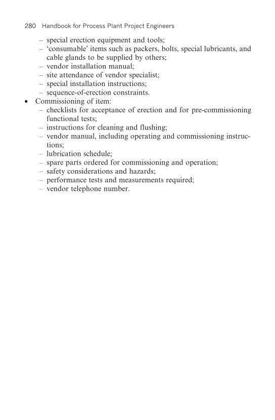
280 Handbook for Process Plant Project Engineers
– special erection equipment and tools;– ‘consumable’ items such as packers, bolts, special lubricants, and
cable glands to be supplied by others;– vendor installation manual;– site attendance of vendor specialist;– special installation instructions;– sequence-of-erection constraints.
• Commissioning of item:– checklists for acceptance of erection and for pre-commissioning
functional tests;– instructions for cleaning and flushing;– vendor manual, including operating and commissioning instruc-
tions;– lubrication schedule;– spare parts ordered for commissioning and operation;– safety considerations and hazards;– performance tests and measurements required;– vendor telephone number.

Change and Chaos 281
Chapter 26
Change and Chaos
26.1 Change
We started our review of project management, in Chapter 3, by stressingthe fundamental need of planning and working to plan. Inevitably therewill be a need to change the plan. It is unlikely that every event willmaterialize as foreseen, or that arising from the unforeseen, there will beno previous decisions or designs that subsequently are seen to be wrongor sub-optimal.
As we have seen, there are indeed bound to be many assumptionsmade during planning that will inevitably lead to some measure ofrevision and re-work. The issue is not therefore whether to permit anychanges, but how to control them so that they do not destroy themanageability of the project.
Change control has a few components: change recognition, changeevaluation, change approval or rejection, and change implementation,including the consequent revision to plan. These are discussed below.
• Change recognition may sound an odd subject to the uninitiated,but it is a fact that changes are too often made inadvertently orsurreptitiously, with damaging consequences. An error is in generala form of inadvertent change from what was intended. Once an errorhas been made, it may be discovered and consequently the relevantwork may be surreptitiously changed, with unforeseen repercussions.
Process plant design and construction is such a heavily interlinkedexercise of different activities and disciplines, that the consequencesof change are very easy to underestimate. In fact ‘change’ isinvariably one of the most emotive issues in the business.
Change recognition is mainly dependent on the training andconscientiousness of the work performers and their supervisors. It is

282 Handbook for Process Plant Project Engineers
essential to have a climate in which it is unacceptable to carry outchanges without formal notification to the other team members,or without approval subject to agreed procedures. Of course, adraughtsman or engineer is still entitled to use his eraser (or delete-key), and that does not automatically constitute a change asenvisaged. It is only a project change if the document has alreadybeen communicated to someone else, and this distinction must beemphasized. The prevention of issue of drawings, or indeed anydocuments incorporating revisions, without any change to the revisionstatus is one of the perennial management ‘change-recognition’concerns. Appropriate programming of computerized documentcontrol systems can be very effective in overcoming the problem.
• Change evaluation is the process of communicating the proposedchange to all disciplines that may be affected, getting their feedback,and evaluating the full technical, schedule, and cost impact ofthe change. There is some skill and experience involved in ensuringthat all affected parties and work are included. This process maybe greatly improved by the meticulous record and recall ofinformation use, but this ideal seems to be quite difficult to maintainin practice – much information is passed on informally.
Following the receipt of feedback comes a process which maydemand as much engineering knowledge and ingenuity as theoriginal plant design: the development of ways of implementing thechange and overcoming negative consequences. Once these areunderstood, there is a process of evaluation and optimizationleading to a decision on the best way of handling the change, and anestimate of the associated costs and schedule implications.
The implications of a change to all facets of the project work areusually called the ‘impact’. It has long been realized that the impactis much heavier in the middle of the design process than at thebeginning or end. At the beginning, when designs are conceptualrather than detailed, not much other work is likely to be affected,and users of information understand that it is provisional andsubject to confirmation. At the end, the implications of changeare much clearer and work currently in progress is not affected.As a result, when estimating the consequences of change, severalorganizations apply an ‘impact factor’ (ranging from 1 to as much as4) to the first estimate of additional manhours, depending on thestage of the project.
• Change approval or rejection is a management or client decisionbased on the change evaluation and consequent recommendation.

Change and Chaos 283
At this stage there may be disputes about whether a change isa ‘change’ for which the client bears responsibility, or an ‘errorcorrection’ for which the project team bears responsibility, and adispute resolution procedure may be required. The project engineer’sattention is drawn to the strategic precepts outlined in Chapter 7on how best to handle such situations, the most important of whichis to be well-positioned before the conflict arises by meticulousproject scope control and the elimination of ‘weasel words’ in designcriteria.
• Change implementation has to be rigidly controlled and followedup. The follow-up system has to ensure not only that all relevantproject work is revised accordingly but also that all consequentdocument revisions are received and utilized by all who had theprevious revision, which must be destroyed or visibly cancelled.
Change on a project of significant size cannot possibly be managedwithout adequate procedures that embrace change recognition, changeproposal notification, change evaluation, change approval, changeimplementation, and document revision. As part of these proceduresit is inevitably necessary to maintain numbered registers ofchange proposals, change notices (which record the evaluation andrecommendations), and change orders.
The work of evaluating a proposed change can be extensive and canimpact heavily on scheduled work performance. And yet anything to dowith a change has to receive priority: delays tend to greatly increase theimpact of implementation – more work has been done that has to bechanged. It is therefore customary to follow a two- or even three-partprocedure for change control (whereby quick decisions can be made asto whether to proceed with more formalized evaluation or whether todrop the proposal) and to allow certain categories of minor change to beprocessed informally, subject to appropriate authority level.
26.2 Chaos
The following message may be found displayed at the workstations ofmany process plant project engineers:
‘From out of the chaos, a small voice spoke to me and said Relax andbe happy, things could be worse. So I relaxed and was happy … andthings got worse.’

284 Handbook for Process Plant Project Engineers
The fight against chaos is a subject of constant awareness by even themost methodical of process plant engineers, however good the systemsemployed and however well-drilled the project team. Chaos takes manyforms, but the general result is an unpredictable working environment:documents not available on time, suppliers and contractors kept waitingfor replies, wrong and contradictory information circulated, and so on.The cause is clearly that the project team has become overloaded in itscapacity to deliver the right goods at the right time. The effect inevitablyincludes not only reduction of quality, which in the case of engineeringessentially means too many mistakes or omissions in the informationissued, but also failure to meet schedule commitments. There alsoinescapably follows an overrun in both direct field costs and theduration and cost of engineering itself, as efficiency levels deteriorate. Infact as the effects build up on each other, it is easily possible for theproject to spiral out of control unless firm management action is taken.
Fig. 26.1 Chaos

Change and Chaos 285
Project teams can be chaotic from the start, almost irrespective ofthe load placed on them, through failure to properly plan and organizetheir work, for example because the complexity of the project isunderestimated, because concepts are not frozen before commencingdetail work, or because of inadequate competence. The ability of aproject team to deal with complex tasks when stretched to their limit is aquantitative matter. On a scale 0–100, for different teams there will bedifferent scores, depending on the teams’ training, individual skills,systems employed, and quality of management.
The load placed on a project engineering team is the demand made onthe team to produce quality information on time. As we have observedin Chapter 7, The Contracting Environment, various circumstancessurrounding the creation of a project, and in particular a competitiveenvironment, may combine to set the project team a challenge – a load –which even at the outset may be at or beyond the limits of its capability.On the other hand, where little competition exists, quite a pedestrianperformance may be sufficient. Some elements of the challenge may becomparatively quantifiable, such as the manhour allowance per drawingor purchase order of a particular type. Some are not so simple, forinstance the influence of parallel activities, assumptions and consequen-tial re-work (which are necessitated by the schedule compression) or,generally, the number of design iterations needed for whatever reason.
On top of the load placed on the project team at the project set-upstage comes an additional load placed by changes and events beyond thecontrol of the team. These include the following.
• Process changes, changes to the process flowsheets, or changesin fundamental process information, typically made because oftechnology development, the late appreciation of better technologicalpossibilities, changed site conditions (feedstock, operational needs,costs, etc.), or changes to the product market.
• Other design criteria changes – usually driven by cost or time‘surprises’ – when unexpected consequences of specification anddesign choices become apparent at the procurement stage, andchanges are required in order to maintain the project budget orschedule, or to take advantage of opportunities for improvement.
• Changes required to counteract the effects of poor performance bysuppliers or contractors; for instance if an equipment supplier has tobe replaced by another, the adoption of proprietary equipmentdesigns different from those used for the design of interfacingstructures, electrical supply, and connecting piping.

286 Handbook for Process Plant Project Engineers
• Correction of errors made in the conceptual work undertaken beforeproject commencement, or in the project work as it unfolds.
In summary there are two components to the load placed on theproject team: the load of producing initially defined information(document production, follow-up, inspection activities, and associatedreporting), and the load of changing or adding to the informationand its basis as the need arises. Some components of the latter may beanticipated and allowed at the project planning stage, others may not(or can not) be anticipated.
Returning to the subject of overload prediction, and defining theproject team ‘workrate’ as the load of work per unit of time, we havefrom the above the basic equation
Workrate requiredinitial WBS changes
schedule duration
1
= +
This must be compared with
Workrate capacity team competence and motivationresource incre
=+ aases
If the project team, by whatever reasons of competence, experience,and good organization, has a workrate capacity which exceeds theplanned requirement, in a challenging environment there are variousfactors which tend to cause the workrate required and the capacity tomove into equilibrium, outlined below.
• As the work advances, the client may demand more changes, seeingthe apparent ability of the team to cope with the inevitable pos-sibilities of design improvement. These changes may well be initiatedby the project team members themselves.
• There may be a desire to use up more time in commercial negotiationin order to get better deals from suppliers and contractors, therebyeffectively compressing the engineering schedule to maintain theoverall project schedule.
• Project resources may be diverted to other work that seems at thetime to be more pressing.
• The project team motivation may be reduced, typically by a corporateexecutive outside the project team who sees some opportunities to
1 Work breakdown structure, as planned.

Change and Chaos 287
make petty economies by cutting benefits, or by not maintainingthem in an inflationary situation.
However, there are environments which are not challenging, wherechanges are hardly allowed, resources are not diverted, and plans andcommercial interfaces are generally quite rigid, most normally ingovernment projects. But even here, capacity may be reduced as projectteam members (especially the more capable ones) depart in search of amore challenging environment.
However high the initial capacity, the usual situation is thatthe workrate capacity and workrate requirement rapidly come toan equilibrium, which requires management effort for its furthermaintenance. Chaos can be expected if the workrate required exceedsthe capacity, although most teams will rise to the occasion if thiscondition is not too prolonged. Nevertheless, certainly there is anoverload intensity and duration at which performance begins to fall offexponentially.
Because of all the variables involved, it is not easy from a projectmanagement viewpoint to predict the precise workrate at which chaoswill escalate. Rather it is necessary to look for the signs of impendingchaos, and then know that urgent management action is necessary, inthe form of the following.
• Accept less changes.• Decrease the initial WBS; shed off some of the load, for instance
peripheral parts of the plant, to another team.• Extend the schedule, that is, the real engineering schedule – not the
apparent schedule, which does not account for information delaysarising from extended commercial negotiation, late client decisions,poor vendor performance, and so on).
• Add more resources or improve their quality – not easily done in themiddle of a project, owing to the learning curve. If resources havebeen diverted, it would be far better to recover them.
• Improve motivation. (Fire that bean-counting executive!)
The ‘signs of impending chaos’ include the following.
• An increasing trend of targets missed on weekly progress reviewagainst current targets (that is, after allowing for any rescheduling).
• A high percentage of effort expended on changes and re-work, at atime when output of planned work is behind schedule.
• An increasing trend of delays in responding to technical or commercialqueries (for example, take the site query register, look up the

288 Handbook for Process Plant Project Engineers
outstanding unanswered queries and the days outstanding for each,and add them up).
• Less ‘buzz’ in the office, more cynical remarks, more graffiti, and soon. People do not like working in an environment where they seemto be losing.
It must be evident that a state of chaos is a no-win situation for theengineer, and for the project as a whole. There is no silver lining to thiscloud, no upside benefits to trade against the downside. Efficiency goesdown, quality goes down, and project costs and durations go up. Andyet some clients, or rather their representatives or other managementof the various parties involved in a project, sometimes almost seem tobe conspiring to wish these circumstances on the engineering team inan apparent attempt at group suicide. Possibly this comes about as aresult of ignorance, or maybe from a misguided attempt to maintain aposition of dominance over the engineering team. An engineering teamthat is past the threshold of chaos has no scope for initiative. It operatesin a purely reactive mode, is disinclined to strategize its relationships,and is easily manipulated.
Some engineers find it very difficult to escape from this situation,most frequently when the client or dominant party is both experiencedand cunning, and typically lets out the rope of workrate adjustment incarefully measured little increments, enough to stave off disaster butnever quite enough to let the engineers get right on top of their workand regain the initiative. Engineers who are more successful anticipatethe day when schedule extension or other action may be necessary, andstate categorically what is needed in order to continue to accept theresponsibility for plant safety, and the engineering quality on which itdepends.

Fast-Track Projects 289
Chapter 27
Fast-Track Projects
Initially, a project activity sequence network may be prepared byfollowing the logical sequence of individual activities being performedwhen all the required information, or previous related activities, arecompleted.
1. Equipment is ordered and vendor drawings are obtained.2. Based on these drawings, the steelwork supporting the equipment is
designed.3. Based on the steelwork drawings, foundation plinths are designed.4. Pile designs are prepared.5. The piles, pile caps, and plinths are built, steel erected, and equipment
erected.
However, a project schedule based exclusively on such an orderlysequence of events is seldom acceptable. Having identified the criticalpath (or, after sufficient experience, usually knowing instinctively whathas to be done), it is necessary to reduce the overall planned duration byvarious means.
In Section 4.4, Co-ordinating engineering work, we discussed themost basic methods of shortening the schedule, including in particularthe adoption of standard (or existing) designs. These may involve somechanges to the process flowsheet, and the elimination of uncertainties bysetting conservative design or equipment selection parameters. Thereremain two very common devices to shorten the schedule of engineeringwork: parallel working and assumption of design information. In theirapplication the two devices are almost identical.
In parallel working, two or more interrelated design activities arecarried out simultaneously. For instance, the structural steelwork andpiping are designed simultaneously based on the layout drawings, rather

290 Handbook for Process Plant Project Engineers
than the piping being designed to suit the steelwork after its structuraldesign, as in Fig. 4.1. The efficiency of this process is dependent on suchfactors as the quality of teamwork, the design aids available to assistco-ordination, and the success with which the layout drawings haveanticipated the final structural design.
The practice of parallel working extends into the manufacturing andconstruction phases. Examples are:
• equipment design and manufacture commencing, while secondaryequipment design information, such as positions of piping connections,is still ‘on hold’;
• placing of contracts for construction work before the drawings todefine the details of the work have been completed; and
• the construction of earthworks proceeding before the plant layoutdetails have been finalized.
In the making of assumptions of design information, usually relatedto information from a third party, the progress of design work is basedon the best (or sometimes most conservative) estimate of the information.For example, structural steelwork design may be based on the anticipatedmass and dimensions of a supported equipment item for which finalvendor’s information is not yet available. Evidently the accuracy ofthe assumptions, the designed-in flexibility to accommodate incorrectassumptions, and the ability to influence the equipment item vendor tocomply with the assumptions (or the freedom to choose a compliantvendor) will affect the efficiency of this process.
If the assumptions to be made relate to the performance of work byanother project engineering discipline, say if the mechanical engineerorders a pump before the process engineer finalizes the calculationswhich will affect the required performance, it is clearly only a matter ofsemantics whether the practice is described as an assumption or parallelwork.
If work proceeds in parallel or by assumption, there is clearly apossibility (for a large amount of such work, a certainty) that there willbe some errors and inconsistency. Time and resources must be allowedto detect the problems and correct the work in the design office, redesignthe equipment being manufactured, modify the construction on site, ora mixture of all three.
The practices outlined above are effectively a means of breaking thelogic of schedule dependency; there are also other ways of going aboutit. One method quite often practised at the civil/structural-steel interfaceis to work ‘from both ends towards the middle’. For instance, there may

Fast-Track Projects 291
be a piece of process equipment to be supported; information about theprecise interface dimensions and holding-down bolt arrangement isdependent on getting final vendor information, which is itself dependenton a whole series of events, including order placement. On the otherhand, there is a critical requirement to commence work on the founda-tions, which as outlined above are designed to suit the structuralsteelwork, in turn designed to suit the supported equipment. Thedependency may be broken by deciding instead (if it looks to be areasonable technical solution) to design the structural steelwork to suitboth the foundation and the equipment. This makes it possible to get onwith the foundation design and construction without waiting for theequipment vendor’s information.
The last example will be seen to be one of very many possiblevariations: for example, designing the steelwork and/or the foundationin such a way that it can accommodate a sufficient range of equipmentdimensions, or arranging for the foundation/steelwork to be adapted onsite as may be required.
In fact, on closer examination, all these methods of shortening theschedule are seen to be one and the same action, which is to reject thelimitations of sequential activities, stipulate that certain activities willcommence at the time required to suit the schedule, and then devise aplan to overcome the consequences. Clearly such an approach can betaken too far, when everything is ordered and sent to site without muchdesign integration at all, to be ‘fixed up on site’. This is not recom-mended; but from a philosophical point of view, in search of the bestplan, it may be just as instructive to start from this ‘ultimate disorder’scenario as to start from the ‘logical sequence’ network.
Summarizing the above, the sequencing and scheduling of engineeringwork is rarely a simply determined process. It usually includes com-promises to accelerate the work by reconsidering design and procurementparameters, by parallel working, by making assumptions, and bygenerally challenging the initially adopted sequence logic against theconsequences of acceleration, as reflected in increased design error andadditional site work.
The difficulty of deciding on the best compromises with regard toparallel working and assumptions increases exponentially with the sizeand complexity of the plant being built, principally because of theknock-on effect of design revisions and errors. The engineering manageris well advised to be more conservative (in estimating the consequencesof engineering schedule compression) when planning larger projects.
To illustrate, in a project and industry background, some of the

292 Handbook for Process Plant Project Engineers
problems and opportunities which can arise, here are the outlines of twoprojects where a fast-track approach was adopted.
27.1 Case study A: Fabulous Fertilizers’ new plant
The client, FF, predicted that the market for its product would becomegreatly improved in the next northern-hemisphere season, but to takeadvantage of this opportunity, a major capacity expansion had to becommissioned within 12 months. The last similar plant construction hadtaken 16 months to complete. FF’s project engineer studied theschedules and close-out reports for similar projects, and concluded thathe could knock 4 months off the last project schedule if the followingconditions were met.
• Procurement of the major process equipment items began immediately,based on extrapolation of previous project data (without waiting forproject-specific flowsheets and mass balance to be finalized). Thebasic data for the equipment would then become requirements forflowsheet and data sheet preparation, rather than vice versa. Designdetails arising out of plant layout could still be accepted severalweeks after purchase commitment.
• The longest delivery item, the reactor, was ordered from the supplierfor a previous project at the same price per ton, thereby saving thetime for competitive bidding.
• The plant was separated into three distinct modules, instead of theprevious practice of a single integrated unit. This would enable himto concentrate his (limited) design team on the design of the reactorsection without regard to the other two simpler modules, whose delaycould be accommodated. The penalty for this was two additionalpiperacks, extra pipework, and a need for more ground, but therewere also other beneficial spin-offs: separate and less expensiveconstruction contractors could be used for the two smaller modules,and the feed preparation module could be commissioned and used tobuild up intermediate feedstock, while it was still safe to carry outhot work on the reactor section.
No other short-cuts were required to FF’s normal project practice,and the project engineer decided to maintain all his normal projectprocedures rather than risk the consequences of impromptu short-cuts.The project engineer took the trouble to discuss the whole philosophywith FF’s commercial manager and procurement department. They

Fast-Track Projects 293
agreed with him on an absolute maximum 10-day period for the assess-ment of equipment bids, and 1 week further for negotiation and orderplacement, and also suggested that a few traditional bidders be eliminatedbecause of a record of tardy performance.
FF got their plant commissioned within the 12-month period – butnot without additional, unforeseen costs and problems. Constructionplans had to be changed a few times, as insufficiently thought-outdesigns had to be modified in the field, but it was no coincidence thatthe errors occurred in the less critical areas where there was someflexibility to make changes. And undoubtedly, some premium was paidfor abbreviating the procurement deliberations and for excludingvendors and contractors who were adjudged unable to meet the schedule(although most of them claimed otherwise). The extra costs of fast-tracking the project were considered to be far less than the commercialbenefits of early product delivery.
27.2 Case study B: Magnificent Metals’ new gold plantMagnificent Metals, MM, is a very big organization that owns manygold mines, mainly designed by their own projects department, headedby Ivan the Terrible. The projects department had become a veryexpensive institution, which took a long time to deliver plants thatembodied many unnecessarily expensive features. Ivan’s new managingdirector, Smart Alec, decided that MM’s new venture, Soggy Swamp,would be designed and built by contracting organizations and not bythe projects department. Ivan’s role was restricted to that of owner’sengineer, responsible for specifying the plant and supervising thecontractor. The shareholders were informed of the venture and itscommissioning date, set to coincide with the expected upturn in the goldmarket in 3 years’ time.
Ivan commenced the specification of the project works, but was besetwith difficulties, principally that the ore mineralogy and grade werefound to be somewhat uncertain. Ivan decided on a campaign of oresampling and process testwork. He had made his reputation by gettingthings right – not by taking chances (he has no understanding of theword probability) – and he took over a year to finalize the basic processdesign parameters. Alec became increasingly impatient, and perceivedthat he might be embarrassed by failing to meet the committedcompletion date. But with only 18 months in hand, the plant was stillinsufficiently specified to permit a lump-sum bidding process by the

294 Handbook for Process Plant Project Engineers
contractors – Ivan was quite adamant that only rubbish would bedelivered if this was attempted. He needed to be able to participate indetail design decisions. It was therefore decided to engage in a competi-tive bidding process to appoint a managing contractor, who was tobe payed a fixed price for EPCM (Engineering, Procurement, andConstruction Management) services. All direct field costs would bereimbursed by MM.
The winning bidder was the Always Adventurous constructioncompany (AA). By this time there were only 16 months left untilcompletion of commissioning. The project had become fast track,something of which Ivan had no experience. ‘No problem’, said AA.‘We have done this before – we commissioned the Desert Gold plant inunder 16 months, and look how well it functions’.
Now we will not belabour the reader with all that went wrong withthe Soggy Swamp project. It was a disaster: never on schedule and, dueto the ensuing pressures and ill-considered short-cuts, also technicallyunsatisfactory and with a cost well over budget. We will rather dwell onthe differences between Desert Gold and Soggy Swamp, as Alec andIvan finally recognized them in hindsight.
The main difference was the degree to which design basics had beenfinalized before the contract award. AA were awarded the contract forDesert Gold after a detailed study characterized by the following.
• Flowsheets had been developed to a stage where the mass balancecould be frozen for all the main process streams. Not so for Soggy – 2months into the project schedule, AA’s process engineers were stillarguing the interpretation of the process testwork (not all of whichhad been divulged in the bidding process) and the consequences tothe flowsheets.
• All the main equipment design parameters had been set, bids hadbeen solicited accordingly, and vendors chosen. At the outset ofDesert Gold, purchase orders for the main equipment items couldimmediately be negotiated with the vendors, based on the previousbids. Not so for Soggy: bids had to be solicited from scratch, andfirst the process data had to be finalized.
• The Desert Gold layouts had been extensively reviewed and optimized,and coarse-scale Hazops had been held for the more important plantareas. The Soggy layouts were being reconsidered well into detaileddesign, and when AA were finally compelled to carry out Hazops(‘Hazops for a gold plant? We’ve built ten of them without anyproblems’), Ivan’s team felt obliged to require some major re-work.

Fast-Track Projects 295
Apart from physical differences such as starting from a different base,there were equally important differences in personnel and humanrelations. The lead engineers on Desert Gold had all been involved withthe study and got to know the owner’s supervisory team, whichconsisted of only four individuals. Personality clashes and differences oftechnical approach were behind them. Moreover, the Desert Goldowner’s project director had insisted that their project manager and hissupervisory team be given significant incentives for meeting all theproject objectives. No such luck for Ivan’s 20-man team. They camefrom the projects department’s rigid background and ideology, andinsisted that they must check every design detail and obtain perfection.They received no reward for completion on time, and saw only theprobability of criticism if the design was imperfect. It may be remarkedwith surprise, then, that some of the design work turned out to be verypoor. The answer is that one of the most important factors is co-ordina-tion, and a plethora of supervisory specialists does little to help that,and often much to hinder. Another important factor was that it becameimpossible for AA to keep all their best engineers and techniciansworking on the Soggy project – many resigned rather than work withthe ‘Terrible Team’.
By Ivan’s requirement, the AA contract included rather punitivedamages for the consequences of design error. The AA team weretotally disinclined to make any assumptions that might accelerate theproject, but rather dissipated their ingenuity in writing clever letters totheir client, pointing out how the client team was alone responsible forall the delays and re-work.
Now, we have labelled Soggy Swamp as a disaster, but that is onlybecause we have information that is otherwise privy to Smart Alec,Ivan, and the project teams. In fact Alec’s reputation could affordno such disaster, and when (a few weeks later than the plannedcommissioning date) he understood how bad the outcome was,he initiated a public relations campaign drawing attention to thecompletely unforeseen difficulties arising from the unique features ofore mineralogy. He diverted funds from other allocations into theproject coffers, and embarked on an expensive plant upgrade (for whichAA were paid handsomely). Eight months later, he trumpeted thesuccess of Magnificent Metals’ experts in overcoming all the problems,and AA had another good project reference to their name, enablingthem to win the bid for Happy Half-wits’ new process unit.

This page intentionally left blank

Advanced Information Management Systems 297
Chapter 28
Advanced Information ManagementSystems
Project engineering and management consists of a number of types ofindividual activity, surrounded by a mass of information flow, whichconnects the activities according to certain procedures. The scope forenhancing project performance by utilizing advanced managementinformation systems has been obvious since more powerful computersbecame generally available. Many such systems have been and continueto be developed. A few of the typical features and aspirations follow.
• All information flow may be set up within the computer network bypaths that reflect the project procedures and workflow.
• ‘Intelligent’ P&IDs may be set up, from which information such asequipment lists and pipeline and instrument data are automaticallytransferred to those disciplines. All information regarding a P&IDitem may be accessed by clicking on the item.
• Equipment data sheets, purchase orders, and contract schedules maybe formatted on standard templates which reflect the ordered, single-entry-point information flow from one discipline to another, withthe required approvals built in to the route of passage.
• The information systems can be combined with advanced plantmodelling systems, and interface to external software packages, suchas for process modelling and pipe stress analysis.
• Before a drawing or model is commenced, the associated input ofspecifications, calculations, preceding and other-discipline drawings,and equipment vendor information may be made availableelectronically to the designer without need to identify the inputs andcollect them each time they are needed.
• The more mechanistic drawing processes, such as electrical and

298 Handbook for Process Plant Project Engineers
instrumentation lower-level diagrams and schedules, may be generatedfrom the P&ID and engineering database without much designer input.
• Drawings may be automatically compared with design data such asP&IDs.
• Documents may be electronically circulated for review by a definedcirculation list according to document type, and may not be issuedor revised without the appropriate approvals.
• Project control schedules may be automatically collated, for instanceby electronically linking cost schedules to information in the purchaseorder.
• Reports of all types may be formatted as the user may require. Costreports may include breakdown by area, discipline, activity, orwhatever a specialized user requires. Likewise, progress reports,discipline productivity reports, quality check records, and cash flowreports and forecasts can be generated from the same database.
• Engineering managers may receive at the beginning of each week astatus report on work required according to project plan, criticaloutstanding items, and changes made and under consideration – allquickly and automatically.
• Design databank, standard calculation software, and back-upinformation may be made electronically available in the context inwhich they are utilized.
• A list of affected documents may be produced automatically when achange is made to any project data.
• Materials control may be initiated from the single-point entry of anitem on a drawing or schedule, and from there automatically takenthrough the stages of roll-up, enquiry, purchase (and, maybeseparately, addition to construction contract schedule), inspection,despatch, payment, site stores control, and information recall formaintenance purposes.
• No paper need be utilized for any of the above, and not only thedocuments themselves but all approvals, issues, and revisions will besecurely recorded, and will be made available in a highly organizedand accessible form for the life of the plant.
The most fundamental aspect of integration is the datacentric system,which creates a single-entry database as the heart of the project’sinformation. Documents are no longer data archives; they are simply afocused extract from the database at a point in time. A general exampleof the major system components and their interaction is shown inFig. 28.1. Software providers who have more or less developed such
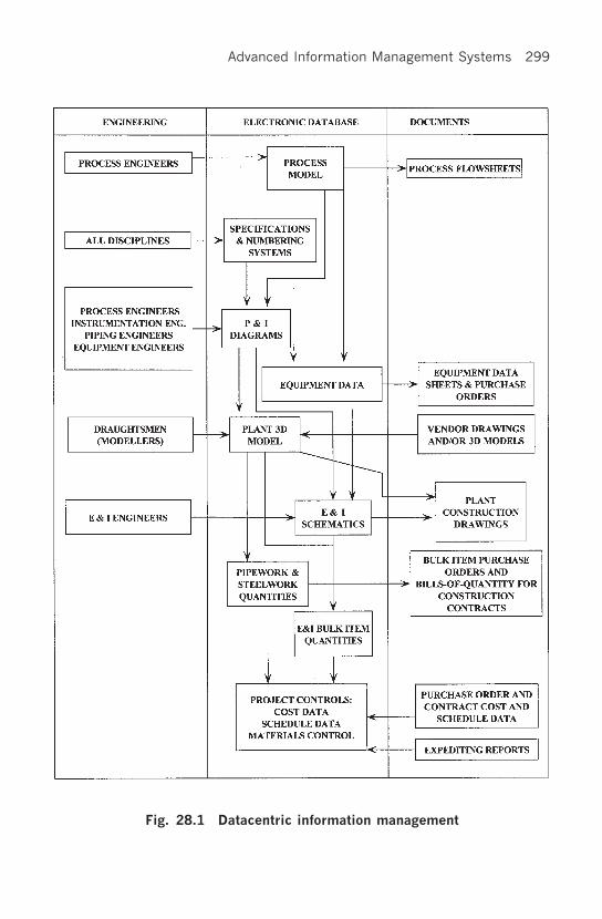
Advanced Information Management Systems 299
Fig. 28.1 Datacentric information management

300 Handbook for Process Plant Project Engineers
systems (or parts of systems) include Cadcentre, Intergraph, and Rebisand Bentley, and more information may be obtained by visiting theirwebsites or contacting their salespeople.
Most organizations dealing with engineering projects have, since thetake-off of modern IT development, invested in and utilized softwarewhich delivers some parts of the total integration, and have experiencedpressure for further integration. The potential benefits are obvious, andthe expectation from clients is inevitable. Clients and even projectmanagers may be profoundly impressed by the wealth of multicolourcharts generated. And yet the application remains limited in relation tothe potential, and there are many, many examples of projects andorganizations that have experienced ‘computer-assisted failure’; this islikely to continue for as long as insufficiently critical users are to befound. These computer systems need to be approached with the sameattitude and caution as a piece of process equipment, except even moreso: the potential consequences of failure are vast.
Some of the common reasons for unacceptable performance are thefollowing.
• Inadequate specification. A computerized information system can beno better than the logic and demands which it is set up to reflect.Despite any number of warnings, organizations will persist indeveloping programs without first developing and rigorously testingthe underlying flow logic and the adequacy of the outputs to allusers. This cautionary note is not restricted to custom-designedsoftware but also to connections between proven proprietary packages.
• Inadequate control of inputs and changes. It is absolutely vital toensure that only the authorized personnel have access to the workfor which they are responsible; that no unauthorized changes arepossible; and that all changes are recorded. For example, if aninstrumentation engineer alters the data of an instrument for whichhe is responsible, this must not make a change to the P&ID to whichthe instrument data is connected, without the authorization of theresponsible process engineer.
• Lack of flexibility. The reality of a project organization is that itdoes not follow strictly logical sequences of operations, but exercisesjudgement when pieces of information are missing or are not final.Assumptions may be made to advance the work, based on takinga view that there is a reasonable probability of being right andthat there will not be too many adverse consequences from beingwrong, etc. It is very difficult to design a system that allows such

Advanced Information Management Systems 301
intermediate choices to permit work to go on, governed by a suitablelevel of extra surveillance and partial revision, which for instance adraughtsman may carry in his head as he develops a design.
The classic example of the project organization hamstrung bysuch lack of flexibility is where every purchase order is delayedinterminably, then issued in the form of a letter of intent (bypassingthe computer system), because the input information is never quiteright for the computer. Accounts are then unpaid because there is nopurchase order, the suppliers cease to perform, and so on. Theproject team blame the computer system, the system designers blamethe project team’s inputs, and frustration continues.
The flexibility issue can also be severe in relation to the controland numbering system demands of different clients, and thefinancial auditing requirements in different countries.
• Underestimation of data input demands. (The old saying: ‘Rubbishin, rubbish out’.) The more complex and far-reaching the computerprogram, the greater the demands for complexity and accuracy ofdata input. This requires training, time, and checking. The checkingroutines have to be rigorously developed and maintained, withsystematic analysis of the probability and consequence of error.Otherwise the system rapidly crashes and everybody blames thelowest level of employee, never the system designer.
• Unforeseen consequences of input error. Developing the previoustheme, it is frequently experienced that certain types of input errorhave unforeseen results. For instance, a letter ‘o’ instead of a zeromay result in a whole item of input disappearing from the system,which may only be realized when an entire pipeline is found tobe non-existent during the course of pre-commissioning checks.Ultimately, such unforeseen problems are only eliminated byexperience of the application.
• Lack of training. Projects, being discontinuous phenomena, arenaturally associated with discontinuous employment and the use ofnew staff. Training needs and the associated time-lags easily lead tothe use of relatively untrained staff over peak periods. All projectpersonnel are involved, not just data input clerks. For instance, asite storeman who understands neither the need for meticulous inputnor the consequences of error – but does understand the need toissue materials promptly under pressure – can and will reduce acomputerized materials management system to irreversible chaos.
• Unreliable software support staff. Software developers mayunderstand that they are well-positioned to make themselves

302 Handbook for Process Plant Project Engineers
indispensable, and take advantage of it. Frequently they are able totalk their clients into financing customized developments, which arethen owned by the software developer but on which the client thatfinanced the development is reliant. The consequences may includeextortionate rates for support services, and an arrogant attitude tothe software users, who are usually well down the organizationaltree from the executive who set up the deal. As a further consequence,the users may adopt an unconstructive attitude to ‘making thesystem work’, and on we go to chaos and disaster.
There is another form of software disaster, in which the key soft-ware support staff simply become ill, meet with an accident, ordisappear, and are found to be irreplaceable, at least within theneeds of the project schedule.
• Underestimation of cost and obsolescence. Looking back on history,it appears that rather few complex computer applications have paidtheir way in commercial enterprises until the particular developmentcame into widespread use. The normal development scenario is thatof a gross underestimation of development and application costs,and an overestimation of effectiveness by everybody ... especially thesalesman. Projects, as opposed to continuous-product organizations,are at a natural disadvantage here. Each project has its differentneeds, and there is no time for system development on the job.
• Insufficiently ‘robust’ software, which ‘falls down’ if an input error ismade, an illegal operation is performed, or simply because of aninherent bug.
• Inability to monitor or forecast progress adequately, because ofchanged work methods. In particular it is no longer easy to measureprogress by documents; it is instead necessary to consider objects. Inaddition, it is, typically, easy to underestimate the ‘front end’ ofdesign, when the comprehensive system of specifications is set up.
In conclusion, the scope of what can be done for the project and engi-neering organization by advanced computer systems is truly wonderful,but the prudent user needs to treat all such systems critically. Utilizeonly those which are rigorously specified, tested on real applications (byreal project people), not over-ambitious, and manifestly will pay theirway in terms of a conservative business plan. There are definite cut-offpoints in project size and complexity below which it is not economicalto operate fully integrated systems. Systems application below thisthreshold should not be attempted unless there are other non-economicfactors such as a client who requires them (usually, for interface intooverall plant information management systems).

Project Strategy Development 303
Final Cycle
Strategies for Success

This page intentionally left blank

Project Strategy Development 305
Chapter 29Project Strategy Development
It may seem odd that this subject, which is the essence of deciding howto go about the whole project, should be left to the end. (The final chap-ter which follows is essentially a summary.) The reason is that it cannotbe addressed economically until all the main issues have been exposedand discussed.
The project strategy is the name given to the highest level of a projectplan. This word tends to be rather misused or abused in managementliterature. What it has in common with the military usage, from which itis derived, is that it addresses an entire plan of campaign (the project).Any specific issues, such as construction or engineering, should only beaddressed in so far as they directly relate to the overall objectives andcannot be settled in a smaller forum. The introduction of too muchdetail, or too low a level of planning, inevitably detracts from focus onthe major issues.
For instance, consider the means of addressing design criteria (thehighest level of engineering planning) during project strategy develop-ment. With the exception of the most fundamental issue, the overallplant performance definition, the design criteria should be addressedas to how they will be formulated (which will be discussed below)rather than their content. There may well be lower-level strategies thanthe project strategy. For instance, it may well pay to organize a multi-functional strategic meeting to discuss the way of formulating andnegotiating a particular construction contract within the overall project.The usual objectives are to ensure that the important engineering,procurement, and construction implications are understood and to derivean appropriate overall strategy, before starting any one function ordiscipline’s work. However, such supplementary strategizing is conductedwith the overall project strategy as a base; it is probably a misuse of theword strategic, but commonly employed when one wants people to‘think big’. ‘Big’ is of course always relative.

306 Handbook for Process Plant Project Engineers
In the nature of organizational structure, there will be a strategy(stated or implied) for the performance of each independent party,and that party is unlikely to perform better than is allowed by theconstraints of his planning ability. If a project is set up as a unitedowner-paid team, with a reasonable structure of partnership by whichall team members participate in the fortunes of the project, one canexpect a single strategy. In the case that the project is set up as alump-sum turnkey operation to be undertaken by a single overallcontractor, there must be at least two strategies: the owner needs hisstrategy for setting up and awarding the contract, managing thecontractor, and getting the best out of him; the contractor needs his ownstrategy for project execution, including the management of his relation-ship with the owner, and for maximizing his returns within the scopeoffered by that relationship.
The fundamental need for strategic thinking for projects lies in thebasic modus operandi for effective project work, set out in Chapter 3:plan the work then work the plan. Work is carried out effectively ifit follows a plan that is subject to minimal revision and minimalquestioning as work proceeds. All issues which might otherwise leadto a change of plan need to be anticipated and dealt with ‘up front’.
These are the essentials of strategic planning, therefore.
• Start from as broad a base as possible and deal with issues as widelyas possible. Any issues which are important to the project, includingopportunities outside of the defined initial objectives, need to beaddressed.
• Make the plan clear. Clarity does not allow the ‘fudging’ of anyissues which could not be decided. It does not include unqualifiedwords like ‘best’, as in ‘best practice’, which simply puts off thedecision in deciding what is best. So for instance, instead ofthe unacceptable ‘best engineering practice’ (weasel-words for amanipulative type of specification), use rather ‘engineering practiceas determined by limiting return value analysis’, or better still,‘engineering practice as per project manual No. XXX’, provided ofcourse that such a narrow definition is correct at the strategic level.There may be a need to identify some aspects of manual No. XXXthat have to be subjected to a process of challenge and modificationfor the project, in which case the definition of that process (butprobably not the outcome) can go into the strategic plan.
• Make the plan inclusive. There will be many decisions that cannotbe taken at the start of the project due to lack of information, but

Project Strategy Development 307
there should be set into motion a process by which the necessaryinformation will be defined, obtained, and a decision made withinthe strategic framework. Try to foresee major potential problems,and address them on this basis.
Inclusivity does not mean that the strategic plan must be verydetailed; it means that such details, when they become necessary,should fall within parameters or policies set in the strategic plan. Themajor part of the strategic plan is the definition and setting out ofguidelines for the further, more detailed planning process. As projectwork is to the project plans, so the project plans are to the strategicplan.
There are many books available on the art of strategic planning, andno doubt the most widely read planners are at an advantage. However,a project is possibly one of the easier environments in which to carry outstrategic planning, because by definition a project starts with definedobjectives. Feasibility studies embrace the most basic target-settingaspects for the project. This creates a potential problem of its own: it isimportant not to be seduced by the preceding study when commencinga project. Take a second look. In conclusion, there are three majorquestions to ask for the purposes of strategic analysis.
29.1 Is the target correct?
This question breaks down into two: is the target attainable, and can wedo better? We have discussed some aspects of unattainable targets inChapter 7, The Contracting Environment, and will not repeat themhere. If you proceed on a project knowing that the target will not beachieved (and there can be some very cynical reasons for doing this),you must also know that overall it will be less efficiently carriedout than if the bad news is accepted up front and realistic planning issubstituted.
The second part of the question always has to be asked, even wheneverything seems to be engraved in stone, otherwise the level of thinkingis hardly strategic. Try brainstorming if necessary. It may be that theclient has very set ideas about the target, and will not countenance anychallenge. That is fine; just ensure that the potential opportunities orimprovements, and the limitation on exploiting them, are recordedin the best way possible with least damage to the client relationship.Usually, any possibilities for improvement will surface again in the

308 Handbook for Process Plant Project Engineers
course of the project, and very damaging they can be at a later date.If the answer to the second part of the question is positive, subsequent
action is fairly obvious:
• evaluate the opportunities fully;• verify that the improvements are real;• decide how their introduction can best be utilized for ‘our’ benefit;• negotiate the changes.
In the case of the project team undertaking work in accordance withclient specifications, obviously the probing and full understanding ofthe specifications/contract is an essential prerequisite to this part of thestrategic planning process.
29.2 How do we get there?
Engineering work is guided by the design criteria, which (after definingthe design objectives) outline how the design will be performed, ratherthan the design itself. At the strategic level we need to ensure that thecriteria are appropriate to every important aspect of our overall projectobjectives.
• Decide whether site visits, visits to other plants, or expert assistanceis needed before finalizing the design criteria or proceeding with anywork.
• Choose the design criteria checklist (for example Appendix 2).• Define the criteria that will influence the answers to the checklist
questions, for instance the following.– Engineering is to be carried out at minimum cost, provided that
a just-acceptable standard is maintained. (Appropriate for acontractor engaging in a lump-sum engineering job that willattract no further business.)
– Plant costs are to be minimized, subject only to safety andergonomic standards corresponding to health and safetyregulations, regardless of any increases of operating cost. (Forthe investor who is tied to a very limited capital budget, butexpects handsome operating profits.)
– Plant capital and operating costs, and the cost of projectengineering and management, are to be strictly optimized on thebasis of 12 per cent per annum discount on future income and 5per cent per annum inflation of product revenue and operatingcosts, for a plant life of 30 years.

Project Strategy Development 309
At the project strategy level there are three further questions to beasked that heavily impact on engineering.
• What resources are needed? Do we have the right resources? Couldwe do better?
• What is the best way of ‘packaging’ the project work at a high level,for example:
– sub-contract large design-and-construct turnkey packages,thereby cutting down on engineering and management costs;
– do everything piece-small and maximize the project team’s owninput.
This decision will be affected strongly by the existence or otherwiseof any restrictions or objectives as to the ratio of IFC to DFC.
• What is the procurement strategy (including the procurement ofconstruction work)? See Chapters 6 and 19.
29.3 What are the major problems?
This question, and the action plan arising, should have been addressedduring risk analysis in the feasibility study (Chapters 9 and 12), but mayneed to be repeated in more depth at the project stage. The high-levelrisk management plan is part of the strategic plan.
In conclusion: already too much has probably been said about strate-gic planning – the whole idea is to think big, and this is not necessarilyfacilitated by an excess of advice.

This page intentionally left blank

Key lssues 311
Chapter 30
Key Issues Summary
This is a summary emphasizing some of the most important observa-tions and conclusions from the preceding chapters. The issues listed hereare important generalities of approach to the job; it should not beinferred that all potentially critical issues are covered. Rather, the listshould be customized at the outset of each project. It is intended as anaide-mémoire for the engineer to take stock at various intervals as theproject proceeds.
30.1 Key project or study issues at the conceptual stage• Developing an understanding of the client culture, and in particular
his expectations in regard to design standards and innovation.• The application of lateral thinking and value engineering. Use as
much ingenuity as can safely be exercised, particularly by the use ofproven techniques in new applications.
• The use of established and defensible estimating techniques.Specifically identify the basis for cost allowances and contingency.Avoid making firm commitments except on a basis of adequateengineering, firm prices from the market-place, and thorough riskanalysis. Be critical in the use of data based on previous projects,especially those set up as self-fulfilling prophesies.
30.2 Key issues at the project execution phase
• Planning and working to plan. The most efficient performance isobtained by dealing with all conceptual issues up front, planning the

312 Handbook for Process Plant Project Engineers
work in successive levels of detail, and sticking to the plans exceptfor minimized and formally controlled change. Adequate planningincludes wide-ranging strategic review, identifying critical items,anticipating problems, and the issue of work procedures whosemandatory content includes only what is really necessary. Cleardefinition and verification of project scope is an essential part ofestablishing the baseline of the plan.
• Maintaining the right balance between time, cost and technicalquality. Do not allow short-sighted individual aspirations (involvingany one aspect) to predominate.
• The making and control of assumptions. In a competitive environ-ment, making a certain amount of assumptions is essential to breakthe chains of unaffordable logical sequence. Exercise control byfollowing through to verify the assumptions and by understandingand allowing for the consequences of wrong assumptions.
• Balancing of work input and work quality. There is good engineeringand bad engineering, but no such thing as engineering perfection.A minimal amount of errors entails many iterations, whichbecome unaffordable. Identify the critical issues that have to beright, and for the rest maintain a balance between extra engineeringcost and the consequences of error. Let neither perfectionists norfalse economists predominate.
• Controlling consultants and any other external experts (includingthe clients’) who participate in the design process. To do thisproperly requires a strategy for each relationship by which there isan advance commitment (or ‘buy-in’) to achieve mutually acceptableobjectives.
• Maintaining a good commercial interface. This requires a com-prehensive strategy linking the goals of design and procurement,and a system of purchasing specifications that is value- and market-orientated.
• Development of sound layouts, which are exhaustively reviewedwith the use of appropriate checklists.
• Control of plant-space. Keep design development under constantreview, and note how each item of space is occupied by eachdiscipline. Identify operator and maintenance space up front, andprevent encroachment. If you are not in control of the plant-space,you are not in control of the project.
• Staying in control of the project. This requires rigid documentcontrol, prompt dealing with problems as they arise, andmaintaining the initiative in contractual relationships (which

Key lssues 313
involves forethought and planning). If there are signs of impendingchaos (loss of control), take drastic action immediately. This mayultimately entail renegotiating the workscope or the time-frame.
• Plan backwards as well as forwards. Have a defined close-out planfrom the outset, including defined close-out documentation, andplan backwards from this point as well as forwards from the present.
30.3 Key issues for the conduct of the individualengineer or engineering business unit
At the study or conceptual stage
• Target-setting and acceptance. Do not be manipulated into accept-ing targets that are not both adequately defined and attainable (anddo not include weasel-words which may hide extra work).
• Contingency management. Do not allow certain cost items ofpresently uncertain value to be sucked into a general contingency.Insist that such items are included in specific ‘line-item’ allowances.Ensure that the actual contingency includes an allowance, basedon experience or statistical analysis, for genuinely unforeseen items,and fight for as much discretionary contingency as possible whileminimizing that of sub-contractors.
• Do not accept liabilities which are out of proportion to the workperformed, or inconsistent with the proposed project scenario (forexample based on engineering perfection in a limited-cost andlimited-time environment).
At the project execution stage
• If unforeseen developments make it impossible to continue theproject without maintaining quality control that is appropriate tothe responsibilities accepted, halt the issue of all potentially suspectdocumentation until the situation is rectified by firm managementaction. Do not be sucked into a situation of continuing chaos.
• Keeping the initiative. Engineering, by its creative nature, createsopportunities for seizing the initiative; take it and hold on to it.
30.4 General business issues
• Management of important relationships (with clients, sub-contractors,partners, and so on). Understand what behaviour is acceptable in

314 Handbook for Process Plant Project Engineers
the cultural climate of the project. Be observant: large projectexpenditures attract rogues with a predatory agenda concealedbeneath an obliging exterior. Spot the rogues and develop a strategyto deal with them.
• Nurturing of quality clients. Recognize the quality clients and striveto give them unbeatable service. Recognize unreasonable clients,and develop a plan to limit your services to the minimum of yourobligations. And if your clients are all unreasonable, what are youdoing in this business anyway?

Jargon 315
Appendix 1
Jargon
As in most industries, many of the key words used have meanings orconnotations not included in the standard dictionary. Sometimes thespecial connotations are subtle; sometimes a whole world of industrialpractice is implied. An understanding of the special usage and interpre-tation of these words is essential to communication in the industry.
Authors of professional and technical literature, especially thosestriving to promote a new discipline, frequently propose a new ‘jargon’to name original concepts. The jargon is considered to be essential tolabel some thing or activity to make it a subject for everyday usage andrecognition within that field. In the case of project management andengineering, the jargon includes relatively few specially coined words,but rather many standard words which in the context of the industryhave acquired special meaning and usage. In general the terminologyhas evolved rather than been coined by an acknowledged author.Although there are various institutions and bodies which aspire tostamp some form of authority on this field, and with it standardizedterminology, there has been no general acceptance. Many words have ausage that is generally understood, but there is also some confusion.
Therefore it is often necessary to define words within a projectcontext, practically as part of the project procedures, especially whenmulticultural interfaces are involved. Words which require particularcare include those used to define the performance parameters of plantand equipment, such as ‘normal’, ‘design’, and ‘maximum’ (we willreturn to this subject), and those which are involved in the relationshipwith a supplier or sub-contractor, such as ‘approval’. Procure-mentrelated vocabulary definitions are a standard part of generalconditions of purchase and contract: the project engineer shouldreview such definitions and their adequacy before proceeding with

316 Handbook for Process Plant Project Engineers
procurementrelated activities, such as the preparation of specifications.Also requiring particular care are the words ‘contingency’, ‘accuracy’,and in fact many of the words involved in defining the breakdown of acost estimate (see Chapter 9).
There are some positively horrible verbal concoctions in widespreaduse for process plant work, for instance ‘deliverables’, which is intendedto mean those products of engineering and management work whichcan be delivered as documentation. No apology is offered for theomission of such slaughter of the English language from these pages,but this is a widely used term that needs to be understood.
A1.1 Definition of design parametersThere are some issues of capacity definition which are often the causeof confusion, with regard to individual plant items as well as to theplant as a whole. Note that individual plant items (equipment, pipes,conveyors, etc.) usually need the facility to function at capacities higheror lower than the theoretical normal in order to allow for surgeconditions, process variations, uncertainties, and so on. There are manynational, industry, and equipment standards (in the context of theirapplication) that define the usage of adjectives such as ‘normal’, ‘maxi-mum’, ‘rated’, and ‘design’, when used to qualify performance parameterssuch as capacity, pressure, and power absorption. There is no overallstandard for the process plant industry. The most frequent confusionarises with respect to the usage of ‘design’, which can be confused asbeing either ‘normal’ or ‘maximum’ (especially by an equipment vendorexplaining why his equipment has failed!).
The project engineer must ensure that these terms are used in thecontext of a standard which defines them, or that a clear definition isgiven, and that there is a common understanding among the projectparticipants. As examples of ‘project definitions’, consider the following.
• ‘Maximum rated’ conditions are the maxima for which continuousplant operation is required. All plant equipment shall be guaranteedfor continuous operation at maximum rated capacity while subjectedto the most severe possible combination of ambient and otherconditions.
• ‘Normal’ conditions are the conditions anticipated for most frequentoperation, and for which optimum plant efficiency is needed.
• ‘Design’ is not to be used to define specific plant operatingconditions, except in the context of a referenced standard or codewhich defines the word.

Design Criteria Checklist 317
Appendix 2
Design Criteria Checklist
A well-drafted set of design criteria will provide a balanced and compre-hensive guide to the development of engineering work, in a way whichexactly meets the performance requirements of the plant and theobjectives of the project. The design criteria should address the plant asa whole, such that the design stages which follow augment the detailwithout the need to revisit the fundamental concepts. Thus the designcriteria should commence with the definition of plant performance(including all the aspects of performance, such as operability andmaintainability, which may determine ‘fitness for purpose’); shouldreference any special, local, or environmental features which may needto be considered for plant design; and should determine the designmethods and standards to be employed. The following are some noteson the essential content.
A2.1 Plant performance
• The process plant product specification. (What comes out of theplant.) This must clearly include not just target values of parameters,but also the limiting values by which the plant product will beaccepted or rejected. It is important to be pedantic and try toconsider all parameters and characteristics which may possibly berelevant: all too many projects have failed because certainparameters (such as moisture content, exclusion of unacceptablesubstances, or size grading) were either overlooked or taken forgranted.
• The specification of the feedstock and imported utilities such aswater, power, and chemical reagents. (What goes into the plant.)

318 Handbook for Process Plant Project Engineers
The same care is required as in the case of the product. In the case ofpurchased utilities or reagents there may be leeway for the projectengineers to determine the specifications, but there will inevitablybe limitations (for example of price or source) which should beascertained at the outset.
• Limitations on plant effluent, waste disposal, and environmentalimpact.
• The plant capacity (its rate of working). This may be definedin terms of quantity of product, quantities of types of product,quantity of feedstock, or a combination of quantities to be producedand processed over a period of time.
‘Period of time’ needs to be qualified, to take into account: theplant operational and maintenance requirements; whether operationis continuous or how many hours per week or year; and the timeallowed for scheduled and unscheduled shutdowns for maintenance,inspection, and repair (collectively referred to as ‘maintenance’). Thestarting point for plant design is usually the ‘average’ capacity (overa long period of time which includes all shutdowns for whateverreason). A ‘normal’ capacity is then calculated for the time whenthe plant is in operation, allowing for shutdowns according to thedefined plant operational mode and the time to be allowed formaintenance; these have a major bearing on the plant design andreliability requirement.
• The required flexibility of operation. The range of capacitiesover which the plant must be operable (or the ‘turndown’) is themost important consideration, but all required abnormal opera-tion should be considered, including initial start-up, normalstart-up, normal shutdown, emergency shutdown, and powerfailure. Sometimes a ‘maximum’ capacity may be defined to pro-vide an extra margin for operational contingencies; however,care must be exercised in the use of this term, as previouslyoutlined.
• Plant reliability, maintainability, and life requirements, consistentwith the plant capacity calculation.
• Requirements for the operation of the plant, limitations onthe numbers and skills of operational personnel, degree ofautomation, and local or statutory regulations which may affectplant operation.
• Special safety requirements, hazard containment, and fire preventionand extinguishing.
• Plant performance testing and acceptance standards.

Design Criteria Checklist 319
A2.2 Plant site
• The site location and document references for topographical andsurvey information, describing the land available for the plant andfor construction facilities, adjoining plant or structures, and access.
• Site ambient conditions (including altitude, maxima and minima ofatmospheric conditions, atmospheric corrosion, wind, and dust).
• ‘Battery limit’ definition and information. Location of points wherefeedstocks, utilities, reagents, etc. are received, where products aredespatched, and up to which roads and site facilities extend.
• Soils report for foundation design.• Hydrological data for stormwater run-off design.• Seismic design requirements.• Local and environmental restrictions that may affect plant
construction.
A2.3 The processThis section may be a document of its own, for example a process tech-nology manual or a set of instructions from a licensor. Refer to Chapter2 for a general description of process package contents. Whereas thePlant Performance section addressed what must be achieved, thissection addresses how the process plant will be configured to achieveit. Apart from the choices and methodologies arising directly from theprevious section, the subjects to be addressed include:
• calculation basis for mass and heat balance;• capacity and other factors to be employed to determine the required
performance of individual plant equipment items;• criteria and methods to be employed for sizing static plant items
such as vessels, stockpiles, and pipelines;• identification of hazards, corrosive substances, and other character-
istics within the process for which special care is required whendesigning the plant (plus details of established practice for dealingwith these hazards);
• process design codes to be employed;• design basis for plant instrumentation and control (often referred to
as the ‘control philosophy’).
The basis for process calculations, special requirements arising out ofprocess needs, and process design decisions should be listed and updatedfor the duration of the project.

320 Handbook for Process Plant Project Engineers
A2.4 Basic plant design features
• Allowance of space, plant configuration, connections, over-capacityof equipment, or other design features to allow for future plantexpansion or possible modification.
• Statutory and government authority regulations and approvals,insurers’ and process licensors’ requirements which may affect plantdesign.
• Corrosion protection systems.• Whether plant units will be enclosed from the atmosphere and, if so,
type of enclosure.• Personnel access and ergonomic standards for operation and
maintenance. Systems and features for removal and replacement ofequipment.
• Size and space requirements for transport vehicles and mobilecranes: turning circles, clearance under structures, and so on.
• Plant drainage system and implications for unit elevations.• Prevailing winds and implications for plant layout.• Design practice for installed standby equipment.• Design practice for emergency power requirements.• Facilities for plant operators and maintenance personnel.
A2.5 Design features for equipment (mechanical,instrumentation, and electrical)
• Applicable international, national, and other standards.• System to ensure maximum economic commonality of spare parts.• Service factors to be employed, such as for sizing of electric motors
and power transmissions.• Features required for plant lubrication, maintenance, and replace-
ment, including vendor support.• Any other features which previous plant experience has shown to be
desirable.
A2.6 Design methodology and standardization
• Standard design codes, methods, software, designs, bulk materialcomponents, and construction materials to be employed for alldisciplines, for example structures, piping, and buildings.

Design Criteria Checklist 321
• System of measure, such as SI units.• Methodology for hazard and operational reviews, and design for
plant safety.• Drafting and modelling standards and software.• Methodology for materials take-off, presentation of bills of
quantities, and materials control, in so far as it affects the designdocumentation.
• Numbering systems for documents, equipment, and code of accounts.
A2.7 Design verification and approval plan
• Within project team.• By process technology supplier (if external to the team).• By client.• By external regulators.• Needs for each engineering discipline.
A2.8 Design and plant documentation for client
• Language(s) to be used on official documents.• Client requirements for format and presentation of documents and
computer disks.• Content and presentation of plant operating and maintenance
manuals.• Project close-out documentation.

This page intentionally left blank

323Index
Abrasion 186, 187Access 112Accuracy 94, 97, 99, 100Agitators 189–191Air slides 179American Petroleum Institute (API) 166Approval 77, 143ASME Standard B31.3 167Assumption 38, 289–291, 312Audit trail for design information 43Authority levels 256Availability 16Average capacity 318
Batch production 16Belt feeder 183Bins 181–183, 229, 230Block plan diagrams 108, 109Brief 278, 279Bulk solids transport 107, 173, 175
angle of repose 174flow 173, 182
Cash flow 83Change 25, 46, 75, 271, 272,
281, 283, 285, 286approval/rejection 282control 281evaluation 282implementation 283recognition 281
Chaos 25, 281, 283, 284, 287, 288, 310, 313Chemical plant 53Chezy formula 196Chutes 174, 176, 177, 183, 229, 230
blockage 174, 175Civil design 230Civil works 208, 209Claims 270–272Client 51, 55, 65, 72Codes of practice 131Commercial appraisal 144Commercial relationship 60Commericial policies and procedures 61Commissioning 29, 273–276, 280
cold 274hot 274plans and checklists 274, 277
Index
safety during 276Communication 34, 277Competitive bidding 61, 67Compressors 164–167, 171
air 163, 164centrifugal 164gas 171turbo-compressors 162, 165
Computer systems 300Computer-assisted design 113Conceptual designs 25Conceptual study diagram 39Construction 28, 33, 257, 259
contract specifications 265, 266management 257
Consultants 238, 241, 312geophysical 238bulk solids flow 180
Consulting engineers 251Contingency 101–103, 311Contractors 59, 70, 72, 265Contracts 59, 61, 63, 65, 68, 265, 269Control 27, 212, 214
system design 14, 233, 235Conveyor Equipment Manufacturers’
Association of USA (CEMA)175, 178, 180
Conveyors 175, 184belt 178, 179, 184, 206chain 179pipe-belt conveyor 179screw 180troughed belt 175vibrating 179
Corruption 60Cost 41
capital cost 77, 78, 144, 145control 33, 41direct costs 57, 58direct field cost (DFC) 59engineering cost 84, 86estimation 56, 94–97indirect costs 56–58indirect field cost (IFC) 84maintenance cost 82management 41manipulation 270operating cost 77, 78, 143, 144

324 Index
Cost-reduction modifications 81Critical issues 42, 217, 312Critical performance factors 16
Data sheets 20Datacentric information management
298Design 32, 130, 221, 239–241
changes 43codes 32, 130criteria 32, 75, 78, 131,
206, 305, 308, 317documentation 32solids-flow devices 174parameters 45, 316process 239standards 46
Detail design 217Detailed engineering 21Documentation 34, 35, 44,
137, 243, 244, 321control systems 33, 243–245indexes 244numbering system 244, 245status 34
Drafting 45, 112, 113, 217Drainage 201Ducts 168, 169Dynamic head loss 157Dynamic loads 206
Economic environment 77Economic model 120Economic trade-off 82Electric motor and other consumers list
210Electric power 14, 210Electrical design 209–212, 236Electrical substations 236Electrical switchgear panels 236Elevators, bucket 179Engineering 28
co-ordinating 44excellence 43front-end 38interface 60, 257management 40, 42manhours 35optimum amount 84plan 61quality 42, 43resources 46scope of work 31work sequence 37, 291
Environmental health 130, 183EPCM services 68–70, 74
Equipment 141–143, 227mechanical 14, 106, 320maintenance and replacement costs 81selection 141, 142support blocks 231
Estimates 99, 100, 311accuracy 99, 100
Euler’s analysis 155Expediting 150, 151
Feasibility study 23, 69, 77, 91Feeders 181–183Field erection 279Flowsheet and mass balance diagram 15Fluid handling systems 107, 153Foundations 14, 208, 232Fractional dead time 128, 129Frequency-controlled variable-speed
drives 211Front-end engineering activities 38
Gas transport 162, 164General arrangement drawings 36,
105, 240Gravity flow 181Guarding 184
Hazan 127, 129, 130Hazards 123, 124, 130, 131, 184Hazop 18, 124–127, 130–132, 202Head 153–156, 158, 185, 188
adiabatic head 163coefficient 155loss 157net positive suction head (NPSH) 170,
171Heater outlets 193Heavy lifts 261Hoppers 182, 229, 230Hydraulic design 195Hydraulic diagram 198, 200–202Hydraulic radius 195Hydrocarbon processing 52
ICI 124Impeller 155Information management 260, 297, 302Innovation 25, 117Inspection 145–151, 279Instrument
access 214mechanical interface 213total cost 216
Instrumentation and control 212, 213,233, 235
ISO9000 43

325Index
Isometrics 168Iteration 38, 44, 45, 106
Jargon 315
Key issues 311
Layout 20, 105–108, 111,214, 231, 236, 312
Layout drawings 36, 105, 110, 115Licensor 21Lifecycle considerations 78Loss management 123Lump-sum 33, 66
construction contractor 264contract 269EPCM contract 74turnkey projects 70, 73
Manning formula 197, 198Marketing 70, 71Mass balance 14Materials
control 298specification 158storage facilities 13transport 13, 36
Metallurgical industry 52Models 112, 113, 241
Negotiation 62, 63Net present value (NPV) 78, 79New technology 71
Offsite facilities 14Open-channel flow 195, 198Organizational structure 306Overhead travelling cranes 207Owner’s engineer 250
P&I diagrams 15, 17, 201Packaging the project work 309Parallel working 38, 289–291Pay-back period 79Permits-to-work 132Permitting 130Perry 3Pharmaceuticals 19Pilot plant 92Pipe 157
plastic 157size 157support 158, 222
Pipeline 258, 189list 169, 170velocities 157, 186, 187
Piperacks 223–227Pipework reactions 192Piping 156, 158, 168, 170, 221, 227
hot 224design 20, 167, 188, 226engineering 167layout for pumps and compressors 170
Plan 26, 47, 313master plan 25, 26
Planning 25, 278, 311inspection 148engineering work 31
Plantcapital cost 95commissioning 273cost 105design criteria 13, 32, 33, 212drainage 195, 201, 208handover 274, 275layout 105, 131, 192lifecycle 18, 23, 77modelling 45modifications 132normal capacity 318optimization 117, 120own-and-operate 69performance 67, 317
Plant and equipment loads 205Polytropic exponent 162Power plants 54Pre-feasibility studies 94, 97Pre-project engineering 24Pressure vessels 227Procedures 24, 136, 138, 244, 254–256Process 18, 19, 92
design package 130equipment 13, 36flowsheet 14information requirements 20package 20, 319plant 13, 51proposal evaluation 92safety 131technologist 93technology 68
Procurement 28, 33, 45, 59, 60, 63, 135,136, 138, 309
Project 23baseline 38budget 27controls team 29differentiating factors 73fast-track 289lifecycle 23management 27, 29, 33numbering system 244

326 Index
Project (cont.)objective 31schedule 289, 290scope 27strategy 305time schedule 27end-product 26
Proposals 94Pump 155, 158, 160, 164, 166, 167, 170
centrifugal 154, 185, 186curves 160performance 160performance diagram 159positive displacement pump 154, 160selection 187speeds 188suction 170, 171
Purchase and contract conditions 135Purchased equipment information 36Purchasing 59, 135, 141Purchasing engineer 143
Quality assurance 41, 43Quality control 142, 145–149, 313Quantity surveyor 266, 267
Recovery 16Refractory design 238Reinforced concrete 204, 218Reliability 16Reliability and maintainability analysis
120Requisition 138Resource plan 27Risk 97–99, 123
analysis 97commercial 98identification 98management 98, 309legal 99
Safety 16, 123, 125, 127–132, 183, 184Schedule 41
shortening 38, 289, 291Screw feeder 183Semi-continuous operation 16Sequence planning or scheduling 35Setout 258Sewers 201Silos 175, 181Single line diagram 211Site 319
office relationship 262conditions 140
construction procurement 257management 258materials management 260selection 208topography 108
Slurries 185–189, 191, 194, 197pneumatic conveying 185, 191–193pumping 185piping systems 188pumps 187, 188system design 187
Specification 20, 135, 138, 139–141,143,148, 158
Splitter box 199Standard designs 46, 219, 233, 250Standardization 139, 140Steelwork design 218, 219Stockpile 181Strategic analysis 6, 7, 306, 307Structural design 203, 204, 207, 219Structures 14, 203, 204, 207, 208, 218Studies 70, 91–93, 294, 311Suction system 171Surging 166Survey 258
Tanks 189–191, 228Targets 307, 313Technology provider 21, 68, 275Test interval 128Thixotropic 187, 188Three-dimensional modelling 112Time schedule 268
control 34planning 34
Trade-off studies 78, 84Turnkey plant 55, 56, 66Two-phase transport 185, 194
Utilities 13, 14
Valley angle 182Value engineering 117–119, 139Vane angle 155Vendor 142, 143, 145, 150, 274
documents 137drawings 46
Vessels 226–229Vibrating loads 232
Wear at the flow boundary 174Work organization 27, 249, 250, 252Workflow 255Workshop detailing 218

This page intentionally left blank
