handbook of structural stability part iii: buckling of curved plates and
TRANSCRIPT

NATIONAL ADVISORY COMMITTEEFOR AERONAUTICS
TECHNICAL NOTE 3783
HANDBOOK OF STIRUCTUIRAL STABILITY
PABT El - BUCKLING OF CURVED PLATES AND SHELLS
By George Gerard and Herbert Becker
New York University
s
/
Washinqton
Au_st 1957
https://ntrs.nasa.gov/search.jsp?R=19930084510 2018-02-16T09:35:05+00:00Z

Q TABLE OF CONTENTS
Page
SUMMARY ........... ................... i
INTRODUCTION ........................... i
SYMBOLS .............................. 3
PHYSICAL BEHAVIOR OF CURVED ELEMENTS . • • ............ 8
Correlation of Test Data and Linear Theory .... ....... 8Postbuckling Behavior ...................... 9
STABILITY THEORY OF CURVED ELEMENTS ................. ii
Linear Stability Theory for Cylindrical Elements ........ 12Boundary Conditions ...... . ....... 16Solutions Based on Donnell's Equation 17
Case i. Axially compressed cylinders and curved plates . _" • • 18Case 2. Cylinders under lateral and hydrostatic pressure . 20
Nonlinear Stability Theory for Cylindrical Elements ....... 21
Energy Criterion of Buckling ....... ........... 22
CIRCULAR CYLINDERS UNDER AXIAL COMPRESSION . ........... 23
Historical Background 24Buckling Behavior ........................ 25
Long-Cylinder Range ...................... 26Transition Range ........................ 27Numerical Values of Buckling Stress ............... 28
Plasticity-Reduction Factor ........ ........... 29Effect of Internal Pressure ................ • • •.30
CYLINDERS IN BENDING ....................... 31
Historical Background . ....... 31
Behavior of Circular Cylinders in Bending ....... 32Numerical Value of Buckling Stress for Circular Cylinders • • • 34
Behavior of Elliptic Cylinders in Bending • .... 34
Computation of Buckling Stress for Elliptic Cylinders ..... , • 35Behavior of Circular-Arc Sections . • 37
Inelastic Behavior of Long Circular Cylinders in Bending .... 38
CIRCULAR CYLINDERS UNDER TORSION . . . . . . . 40
Historical Background ..... • • . 40
Experimental Data ..... •................... 41Buckling-Behavior of Cylinders Under Torsion .......... 41Numerical Values of Torsional Buckling Stress .......... 42
Plasticity-Reduction Factors .................. 43Effects of Internal Pressure . ...... • .......... •44
Elliptic and D-Section Cylinders • • • 45
i

Page
CIRCULAR CYLINDERS UNDER EXTERNAL PRESSURE ............ 46
Historical Background ..................... 46Test Data ........................... 46
Behavior of Cylinders ..... ................ 47Buckling-Stress Equations ................... 48
Radial pressure . ..................... 48Hydrostatic pressure ................... 48
Effects of Plasticity ..................... 49
CIRCDLAR CYLINDERS UNDER COMBINED LOADS ............. 50
Historical Background ..................... 50Interaction Equations ..................... 50
Axial Compression and Bending ................. 50Axial Load and Torsion ................... _ • 51
Bending and Torsion .......... ............ 51Axial Compression, Bending, and Torsion ............ 51Transverse Shear and Bending .......... ........ 52
CURVED PLATES UNDER AXIAL COMPRESSION .............. 53
Historical Background ..................... 53
Summary of Test-Specimen Details ................ 54Buckling Behavior of Axially Compressed Curved Plates ..... 54Initial Eccentricity ...................... 57Inelastic-Buckling Behavior .................. 57Effect of Normal Pressure .................. 58
SPHERICAL PLATES UNDER EXTERNAL PRESSURE ............. 59
Historical Background ..................... 59
Initial Imperfections ..................... 60Analysis of Initial-lmperfection Data ............ 62Compressive-Buckling Coefficients .............. 64Numerical Values of Buckling Stress ........ ...... 64
Effects of Plasticity .................... 65
CURVED PLATES UNDER SHEAR .................... 69
Historical Background ................ 65Test Data .................. ........ 66
Behavior of Curved Plates Buckling Under Shear ......... 67
Numerical Values of Buckling Stress .............. 67
Plasticity-Reduction Factors .................. 68Effects of Internal Pressure ................. 68
CURVED PLATES m_OER CO_mD S_AR AND LONGr_INALCOMPRESSION .......................... 69
ii
Page
APPENDIX A - APPLICATION SECTION ............... 71
Compressive Buckling ...................... 71Circular cylinders ...................... 71Elliptic cylinders ..... , ................. 72
Curved plates ........................ 72Bending Buckling of Long Cylinders ............... 73
Circular cylinders ...................... 73Elliptic cylinders ..................... 73
Torsional Buckling of Cylinders ............... 73
Circular cylinders .................... 73Elliptic cylinders and D-tubes ................ 74
Shear Buckling of Curved Plates ................ 75Buckling Under External Pressure ................ 75
Circular cylinders ...................... 75Spherical plates ....................... 76
Buckling Under Combined Loads .................. 77
Circular cylinders ...................... 77Curved plates ........................ 77
REFERENCES ........................... 78
TABLES ............................ 85
FIGURES ............................ 91
iii

NATIONAL ADVISORY C(_MITTEE FOR AERONAUTICS
TEC ICAL NCTE3783
HANDBOOK OF STRUCTURAL STABILITY
PART III - BUCKLING OF CURVED PLATES AND SHELLS
By George Gerard and Herbert Becket
SU_&&RY
Available theories and test data on buckling of curved plates and
shells are reviewed. For torsion and external-pressure loa_ings, thetest data are correlated in terms of linear buckling theories for both
the elastic and inelastic ranges.
The cases which exhibit a marked disagreement between linear theoryand test data include those of curved plates and cylinders under axial
compression, cylinders under bending, and spherical plates under externalpressure. These cases have been analyzed by a unified semiempiricalapproach for both the elastic and inelastic ranges which is satisfactory
for analysis and design purposes.
The effects of internal pressure on buckling of elements under uni-axial loads are discussed and data on various combined loadings are pre-sented in interaction form.
INTRODUCTION
In Part I ("Buckling of Flat Plates," ref. i) and Part II ("Buckling
of Composite Elements_ ref. 2) of this Handbook the available theoriesand experimental data are in relatively good agreement. However, in thebuckling of curved plates and shells, which is treated in the present
report, there is considerable disagreement between theory and experiment
in many cases. As a consequence_ considerable reliance must be placedon semiempirical methods using theory as a guide. In order to minimizethe use of differing semiempirical approaches which have appeared in the
literature, a unified presentation of experimental and theoretical resultson buckling of curved plates and shells is attempted.
The fundamentals of the buckling behavior Of curved elements are
described in the section "Physical Behavior of Curved Elements" and thelinear and nonlinear theories relating to stability of curved elements
follow in "Stability Theory of Curved Elements. " The principles presented

2 NACA TN 3783
in these introductory sections are referred to throughout the report.The unification attempted in the various sections utilizes the principles
and theory of the above-named two sections as a guide in establishing semi- _empirical methods where theory is deficient.
Large discrepancies between linear theory and test data have longbeen known to exist for the buckling of axially compressed cylinders.
In the section "Circular Cylinders Under Axial Compression, three basic
concepts are used in an effort to resolve the discrepancies from a struc-ttural analysis and design standpoint. In the first, the relation betweenbuckling stress and cylinder-wall curvature is shown to give correlationwith the data when a semiempirical construction is utilized based on the
limiting data for short and for long cylinders. The transition betweenthese cases is guided by the results of linear theory. The second con-
cept relates to the end effects on short cylinders which result in signif-icant increases in the buckling-stress coefficient in the transition
region.
The third concept, which applies to long cylinders, is based uponthe use of the classical equation for axial-compressive-buckling stress
of a circular cylinder utilizing a coefficient C which is a function
of r/t. Test data lie in a range of large values of r/t, for the mostpart, whereas theory defines the relation between C and r/t forrelatively small values of r/t. In this report the two are shown tocoalesce, thereby providing a continuous dependence of C upon r/t.This permits correlation of inelastic-buckling data with theory for the
pertinent plasticity-reduction factor and depicts -the effect of initialimperfections upon buckling behavior.
These concepts also are used for correlation of buckling of curved
plates in uniaxial compression and spherical plates under external pres-sure. In addition, the data on cylinders in bending are shown to permitunification with the semiempirical theory resulting from these concepts.
The behavior of circular and elliptic cylinders in bending is pre-T!
sented in the section "Cylinders in Bending, in which the concept of a
gradient effect upon buckling stress is introduced. This is applied tothe inelastic range as well as to the elastic range. In addition, thefamiliar modulus of rupture is resolved into its component elements, and
instability in the inelastic range is explored in some detail.
The behavior of cylinders buckling in torsion is described in the,, • 'T
section Cyllnders Under Torsion, in which test data on circular and
elliptic cylinders and on D-tubes of semicircular and semielliptic crosssection are shown to correlate reasonably well with linear theory. The
effect of internal pressure is discussed.

NACA TN 3783 3
Behavior of circular cylinders under external pressure is discussedin the section with that name. Buckling of circular cylinders undercombined loadings is described in the following section, in which inter-action curves and equations are presented for various load combinations.
The behavior of axially loaded plates curved in one direction isdiscussed in the section "Curved Plates Under Axial Compression." The
approach used for axially compressed cylinders was applied here in aneffort to correlate the data with empirical theory utilizing the variousgeometric parameters of the plates. The results of this approach are
not so well defined as those for axially compressed cylinders althoughthe trends are comparable. Data on the effects of plasticity are com-pared with inelastic-buckling theory for axially compressed cylinders.Also, the effect of internal pressure on axial compressive buckling isdescribed.
The buckling of spherical plates under normal pressure is discussedin the section "Spherical Plates Under Normal Pressure." It is shown
that the unified approach used for axially compressed circular cylindersand singly curved plates appears to form a realistic basis for analyzingthe spherical-plate test data. An analysis of initial imperfections is
presented based upon the measured geometric imperfections in the sphericalplates from which buckling test data were obtained. The relation of C
as a function of r/t was constructed from this information and is shownto give reasonable correlation with the test results.
The sections "Curved Plates Under Shear" and "Curved Plates Under
Combined Shear and Longitudinal Compression" pertain to the buckling
behavior of singly curved plates in shear and in combined shear and axialcompression, respectively. The effects of internal pressure and plastic-ity are discussed. The appendix summarizes the results of importance in
analysis and design in a convenient fo_n.
This survey was conducted at New York University under the sponsor-ship and with the financial assistance of the National Advisory Committeefor Aeronautics.
SYMBOLS
An plasticity coefficients
a semimajor axis of ellipse, in.
ao initial imperfection, fraction of sheet thickness

4 NACA TN 3783
B axial rigidity, Et/(l v2)
b semiminor axis of ellipse, in.; also, width of curvedplate, in.
c chord of circular-arc section, in.
C compressive-buckling coefficient for long cylinders
Cb bending-buckling coefficient for long cylinders
D bending rigidity, Et3/_2(1- v2_, in-lb
d diameter of spherical plate (chord width)_ in.
E elastic (Young's) modulus, psi
Es secant modulus, psi
Et tangent modulus, psi
F stress function for cylinders
g exponent in expression for ao
H depth of circular-arc section, in.
K constant in expression for ao
kb buckling coefficient for cylinders in bending
k c buckling coefficient for axially loaded cylinders andsingly curved plates
kp buckling coefficient for hydrostatic pressure
kpl buckling coefficient for flat plate, in general
k s buckling coefficient for singly curved plate in shear
kt buckling coefficient for cylinder or D-tube in torsion

NACA TN 3783 5
ky buckling coefficient for radial pressure on cylinder
L length of cylinder or curved plate, in.
L1,L 2 wave length of buckle axially and circtmferentially as
used in expression for ao, in.
M bending moment, in-lb
m wave number in axial direction of cylinders and singlycurved plates
Nx, Ny,Nxy axial, circumferential, and shear loads applied tocylinder
n wave number in circumferential direction of cylinders andsingly curved plates
p pressure, psi
Rb stress ratio for bending on cylinder
Rc stress ratio for axial compression on cylinders and singlycurved plates
pressure ratio for cylinders and singly curved plates
Rs stress ratio for shear on singly curved plates
Rt stress ratio for torsion on cylinders
Rx stress ratio for axial loading, either tension or compres-sion, on singly curved plate
r radius, in.
critical radius of curvature on section of elliptic
cylinder in bending
S sensitivity factor in expression for ao
Sa section modulus of circumscribed circle, _a2t
Sc section modulus of circular cylinder, cu in.

6 NACA TN 3783
Se section modulus of elliptic cylinder, cu in.
t sheet, plate, or cylinder-wall thickness, in.
U,U o unevenness factors in expressions for ao
u,v,w displacements in x-, y-, and z-directions, in.
X dimensional factor in expression for ao, in.
x,y,z coordinates for circular cylinders and singly curvedplates, axial, tangential, and radial directions,respectively
y/a elliptic cylinder parameter (eq. (36))
Z general length-range parameter for cylinders, singlycurved plates, and spherical plates
ZL = L2(I - Ve2)!/2/rt
7 gradient factor
7_ strain gradient factor
7d stress gradient factor
strain, in./in.
plasticity-reduction factor
buckle wave' length, in.

NACA TN 3783 7
_ magnification factor, kexp/kemp
v Poisson'sratio,Vp- (v_- Ve)(_slE)
Ye elastic Poisson's ratio, 0.3 in this report
Vp plastic Poisson's ratio, generally 0.5
p shape factor for inelastic-bending-stress distribution
normal stress, psi
_b actual plastic stress at extreme fiber of cylinder inbending
_cl classical buckling stress of sphere under external pressure
_i = (_x2 + _y2 - _x_y + 3T2) I/2
_r bending modulus of rupture, M/s c
T shear stress, psi
e cylindrical coordinate
X curvature
Subscripts:
cr critical (buckling stress)
emp empirical
exp experimental
e edge; also, elliptic cylinder
o initial
b bending
c compression; also, circular cylinder
x,y in axial and tangential directions, respectively
8 NACA TN 3783
PHYSICAL BEHAVIOR OF CURVED ELEMENTS
Correlation of Test Data and Linear Theory
In Part 1 of this Handbook (ref. l) the buckling of flat plates was
reviewed. The close correlation of experimental data on the elastic and
plastic buckling of flat plates under various types of loadings andboundary conditions confirms the use of classical linear stability conceptsin such problems. Furthermore, it suggests that small initial imperfec-tions unavoidably present in practical structural elements are unimpor-tant from an engineering standpoint.
In investigating the elastic buckling of thin-wall circular cylinders,curved plates, and thin-wall spheres, classical stability theory has beenused also. In general, however, the close correlation between theory and
test data observed for flat plates is not obtained for curved elements.The amount of agreement varies and depends upon the type of loading andthe geometric parameters of the c_rved element.
The most complete test data are available for cylinders. These datawere reviewed by Batdorf (ref. 3) and were compared with a simplified
linear buckling analysis based on the use of Donnell's equations. This _set of equations as well as others are discussed in the section entitled
"Stability Theory of Curved Elements. " For the purposes here, it willsuffice to compare the results of the simplified analysis with availabletest data.
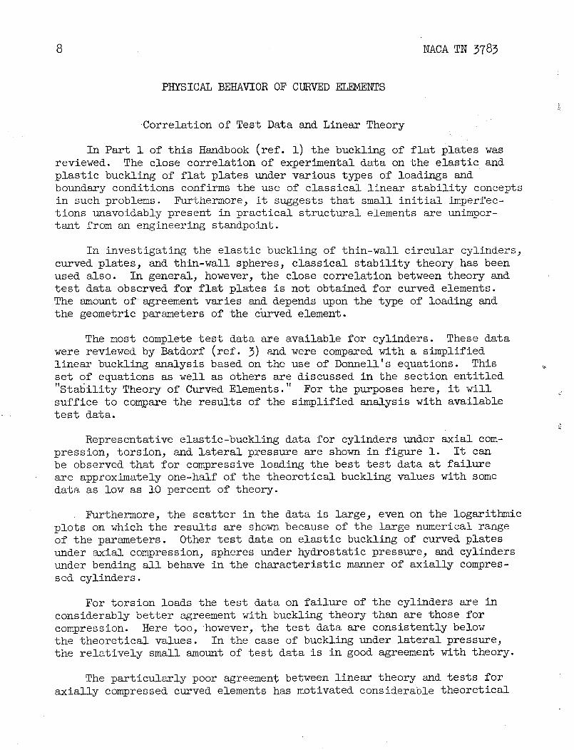
Representative elastic-buckling data for cylinders under axial com-pression, torsion, and lateral pressure are shown in figure i. It canbe observed that for compressive loading the best test data at failure
are approximately one-half of the theoretical buckling values with somedata as low as i0 percent of theory.
Furthermore, the scatter in the data is large, even on the logarithmic
plots on which the results are shown because of the large numerical rangeof the parameters. Other test data on elastic buckling of curved platesunder axial compression, spheres under hydrostatic pressure, and cylindersunder bending all behave in the characteristic manner of axially compres-
sed cylinders.
For torsion loads the test data on failure of the cylinders are in
considerably better agreement with buckling theory than are those forcompression. Here too, however, the test data are consistently belowthe theoretical values. In the case of buckling under lateral pressure,
the relatively small amount of test data is in good agreement with theory.
The particularly poor agreement between linear theory and tests foraxially compressed curved elements has motivated considerable theoretical
NACA TN 3783 9
investigation to determine the cause of such behavior. Some investi-
gators have maintained that such elements are particularly sensitive to
initial imperfections which lead to premature failure. Others haveabandoned classical buckling concepts. By use of large-deflection theoryin conjunction with deflection functions corresponding to the experi-mentally observed dismond pattern, it was found that neighboring large-deflection equilibrium configurations exist at loads less than those of
the linear theory. It has been suggested that the small amount of energyrequired to trigger the jump to the neighboring equilibrium configura-
tions can be supplied by small vibrations in the testing machine. Thus,the compressed cylinder cannot reach the classical load and fails at afraction of this value.
These approaches are discussed at some length in the sections
"Stability Theory of Curved Elements" and "Circular Cylinders UnderAxial Compression." At this point, however, it seems important to inquirefor the reasons for the apparent failure of linear theory for compressivebuckling of curved elements. In this case, large-deflection theory must
be introduced, whereas for torsional buckling linear theory providesreasonable agreement with test data and for cylinders under lateral pres-sure good agreement is obtained.
Postbuckling Behavior
Some explanation on physical grounds is required to indicate when
large-deflection effects may assume importance in particular bucklingproblems. For such an explanation, it is logical to consider the post-buckling behavior of various elements, since this is the region of largedeflections.
A schematic representation of the postbuckling behavior of axiallycompressed colunuis, flat plates, aud cylinders is shown in figure 2 for
both theoretically perfect elements and those containing initial imper-fections. It is assumed that all elements behave elastically.
For the perfect column, the postbuckling behavior is essentially
horizontal in the range of Wave depth/Shell thickness values consid-ered here (elastic effects are negligible) and buckling can follow either
the right branch (0, i, A+) or the left (0, i, A-). The horizontalbehavior can be attributed to the fact that, after buckling, no signifi-cant transverse-tension membrane stresses are developed to restrain the
lateral motion and, therefore, the column is free to deflect laterallyunder the critical load.
The flat plate, however, does develop significant transverse-tension
membrane stresses after buckling because of the restraint provided by theboundary conditions at the unloaded edges. These membrane stresses act

i0 NACA TN 3783
to restrain lateral motion and thus the flat plate is capable of carrying
loads beyond buckling as indicated by the approximately parabolic char-acter of the stress-deflection plot of figure 2. The flat plate alsocan follow either the right branch (0, i, h+) or the left (0, i B-).
For the axially compressed curved plate, the effect of the curvatureis to translate the flat-plate postbucklingparabola downward and toward
the right, depending upon a width-radius parameter. For the completelong cylinder a considerable translation occurs. Note that by shiftingthe parabola to the right buckling would tend to follow the right branchonly (0, i, C) because of the lower loads involved, with the result that
the inward type of buckling is observed for curved plates and cylinders.This inward buckling causes superimposed transverse membrane stressesof a compressive nature so that the buckle form itself is unstable.
As a consequence of the compressive membrane stresses 3 buckling ofan axially compressed cylinder is coincident with failure and occurssuddenly (snap buckling, "oilcanning") accompanied by & considerable dropin load. This is in contrast with the behavior of a flat plate which,because of superimposed tension membrane stresses after elastic buckling,
can support loads in excess of the buckling load.
From figure 2 it can be observed that the behavior of elements with
small initial imperfections tends to follow closely that of the theoreti-cally perfect elements except in the region where _/_cr approaches 1.0.
For columns and flat plates the data for the initially imperfect element
asymptotically approach the theoretically perfect postbuckling curves for
Wall depth/Shell thickness values at which failure occurs. Thus, smallinitial imperfections are relatively unimportant in these cases. For thecylinder, however_ the divergence is greatest in the region where bucklingand maximum load occur simultaneously. Consequently, initial imperfec-tions can be expected to be of relatively great importance in this case
as reflected by the low test data and its large scatter shown in figure i.
From this discussion, it can be concluded that the nature of thetransverse membrane stresses superimposed after buckling provides animportant clue to the discovery of cases in which large-deflection effects
are likely to be important in buckling problems.
By returning now to the data shown in figure I, it is possible tounderstand the degree of correlation between test data and linear sta-
bility theory. As discussed above, poor agreement would be anticipatedfor the axially compressed cylinder since transverse compressive stressesare superimposed when buckling occurs. For the cylinder under torsion,the membrane stresses superimposed after buckling, transverse to the axes
of the buckles, are tensile. Therefore, large-deflection effects wouldbe relatively unimportant and good agreement between linear theory andtest data would be expected.
NACA TN 3783 ii
When a cylinder buckles under lateral pressure, transverse tensilemembrane stresses are superimposed along the generators of the cylinder
and are resisted by the boundary restraints at the ends. In the caseof very long cylinders, this effect would be negligible and the load-deflection characteristics would approach those of a column. Actually,
under lateral pressure, the buckling of an infinitely long cylinder isequivalent to that of a ring. For shorter cylinders, the superimposedmembrane stresses become progressively more important, approaching thoseof a flat plate as the length-radius ratio approaches zero.
The superimposed-transverse-membrane-stress states when buckling
occurs for the cases considered above, as well as for several othercases, are summarized in table i. From table i it can be observed thatin all cases in which significant transverse compressive membrane stresses
are superimposed when buckling occurs, there is unsatisfactory correlationof test data with linear stability theory. For such cases only large-deflection theory must be used. In all other cases, linear stability
theory should be satisfactory.
STABILITY THEORY OF CURVED ELEMENTS
From the discussion presented in the section "Physical Behavior ofCurved Elements" it is apparent that classical stability theory (linear,infinitesimal deflections) yields satisfactory correlation with test data
when tensile (_ O) transverse membrane stresses are superimposed afterbuckling. In cases in which significant transverse compressive (_ O)membrane stresses develop, the buckle form itself tends to be unstableand nonlinear theory (finite deflections) has been used in the attemptto resolve the discrepancies between test data and classical buckling
theory.
It is the purpose in this section to review the mathematical tech-niques available for the solution of linear aud nonlinear problems asso-ciated with buckling of curved elements containing no initial imperfec-
tions. The theoretical buckling load is of importance because it closelycoincides with the failure of cylinders, of wide plates of sharp curvature,and of spheres. For plates of small curvature, buckling marks the regionin which continued application of load results in an accelerated growth
of lateral deflections which ultimately leads to failure.
In small-deflection (linear) stability theory, the deflections areassumed to be infinitesimal. Thus, the strains are linear functions ofthe displacements and therefore the stresses are also linear in displace-
ments. As a result, linear equilibrium differential equations in termsof displacements are obtained. In Timoshenko's book on stability theory
(ref. 4), the solutions for a large number of curved-element elastic-buckling problems are presented. These solutions are based on a set of
12 NACATN 3783
three equilibrium equations which vary only in minor terms from thosesuggested by Fl_gge (ref, 5). The complex geometry involved in distor-tions of curved elements is responsible for widespread disagreement among {investigators as to the proper minor terms to be included in the strain-displacement relationships and hence in the equilibrium equations.
By omitting terms which are of small magnitude when the circularcross section of a thin-wall cylindrical element is distorted, Donnell
reduced the set of three equilibrium equations to a single eighth-orderpartial differential equation in the radial displacement w (ref. 6).For plastic buckling of cylindrical elements, Gerard utilized the simpli-fied strain-displacement and equilibrium equations of Donnell and obtaineda set of three equilibrium equations in the displacements (ref. 7)- These
equations reduce to Donnell's single eighth-order equilibrium equation inthe elastic case.
In large-deflection (nonlinear) theory, the deflections are assumedto be fihite though small. They are large, however, as compared withthose of small-deflection theory. The strain-displacement relations nowinclude nonlinear terms and therefore the equilibrium equations in terms
of displacements are nonlinear. Donnell, in his approximate analysis ofthe effects of initial imperfections on the buckling behavior of compres-
sed cylinders, derived a large-deflection equilibrium equation (ref. 8)which is an extension of that derived by Von K_rmg_ for large deflections
of flat plates (ref. 9). By use of a corresponding energy formulation,Von K_rm_n and Tsien investigated the postbuckling behavior of compres-sed circular cylinders (ref. i0). They discovered that neighboring large-deflection equilibrium configurations existed at loads considerably below
those of classical stability theory. [They formulated anenergy criterionof buckling basedon this behavior which yields buckling loads in reason-able agreement with test data.J _ _
Linear Stability Theory for Cylindrical Elements
Donnell's simplifiedequations for thin-wall circular Cylinders(re£. 6) have been used with a considerable degree of success in buckling
problems. The linear stability theory is based on the following rela-tions between the displacement derivatives and the middle-surface strainvariations and curvature changes that occur during buckling of circular
cylindrical elements:
Q _ACA_N 3783 13
1 = bu/ax
2 = (av/r ae)+ (w/=)
_3= _\Y_ + (i)
xz = a2w/ax2
X2 = b2w/r2b02
x3 = b2w/r ax ae
By use of appropriate stress-strain relations, equations relatingthe incremental forces and moments with the displacement derivatives canbe d@rived. Upon substituting the latter into the simplified equilibriumequations, a set of three equations in terms of the displacements andtheir derivatives is obtained.
Using deformation plasticity theory, Gerard derived a set of equilib-rium equations applicable to plastic buckling of thin-wall circular
cylinders (ref. 7). In the interest of generality, these equations arepresented in equations (2) to (4) and are then reduced to Donnell'seighth-order equation for elastic buckling.
A3 b2u A13 b2v+ fA12+ A3h b2vA1 b2u A13 b2u + ....
bx2 2 r bx be 4 r2be2 4 bx 2 \24/r bx be
A23 b2v A12 bw A23 bw+ = o (2)4 r2be2 2 r bx 4 r2_e

m4 _ACA_N 3783
<A A_I _2u_2v A23 _2v _ _2 A_ _2 + ___2+A2r2_e2 2 r _xbe + 4 8x2 4 8x--_ 4 r _x_e
A23 82u 8w A23 8w+ A2 - 0 (3)
4 r2_82 r2_@ 4 r _x
i r r28x2882 A23 'r38x _83
_A__ _) __ 82w ++ A2 _____v+ A2 + Nx _2w + 2Nxy' _x _8
B 2 8u A23 8u A23 8v
r 8x 4 r 88 4 8x r _@ 8x 2 r
;_2w (4)Ny--+p=O
r2_@ 2
The plasticity coefficients are defined as follows:
Am = 1 - 4
A3 = l-_m 2
A21 = AI2 = i - _dx d 2
A31 : AI3 = _x T
A32 = A23 = _dyT

NACA TN 3783 15
where :
The axial rigidity is:
B = 4_,st/3 (5)
The bending rigidity is:
D = Est3/9 (6)
In the elastic region, _ : 0 and, therefore_ AI = A2 = A3 = AI2 = i
and AI3 = A23 = 0. By replacing the definitions of equations (5) and (6),J!
which are for a fully plastic plate, with B = Et/(l - We2)
\
a_id
f
D : Et3/12(1 - We2) _ respectively, and replacing the coefficient 1/2 by
re, equations (2) to (4) reduce to the following elastic relations:
Ve _wb2u + i - ve _2u + i + ve _2v + - 0 (7)
_x 2 2 r2_e2 2 r _x Be r _x
_2 i -v e b2v i + ve _2 _w__!_v+ +. u + - 0 (8)r2_2 2 _x2 2 r _x _0 r2_e
B _. _u Bv w\ b2w _2w _2wDV4w+ - e--+_+ +_x + _xy +Ny- +p= 0r kV _x r Be rj _x 2 r _x _0 r2_02
(9)

16 NACATN 3783
By suitable manipulation of equations (7) to (9), Oonnell was able
to obtain the following single equation in terms of the radial displace-ment (ref. 6):
Etb4w INx_2W b2w _2w plD_ +r2_ + + _xy +_y- + --0 (10)bx 2 r _x Be r2682
×
The relationships among the other displacements are
83w b3w_u = -v-- + (ll)
r _x3 rg_xbee
V_v (2 83w 83w (12)= _ + V)r2bx28 e r4683
It is to be noted that by letting i/r = 0 and replacing r _8by by, equations (4), (9), and (i0) reduce to the governing equationsfor flat plates.
Boundary Conditions
The usual boundary conditions for flat plates discussed in Part i(ref. l) apply directly to curved plates. However, a complete cylinderhas only two boundaries (at the ends) instead of the four of a rectangularplate. Thus, for the cylinder, two of the four sets of boundary condi-
tions are replaced by the condition that the displacements are cyclicfunctions of the angle 8 with a cycle length of 2_r.
For cylinders which can be classified as long, the boundary condi-tions at the ends have a negligible influence on the buckling stress.
At the other limit, short cylinders approach flat plates in their behaviorand, consequently, boundary conditions are of considerable importance insuch cases.
Appropriate boundary conditions on the displacements, u, v, and wcan be handled in a straightforward manner in cases in which equations (2)to (4) or (7) to (9) are used. However, boundary conditions on the dis-placements u and v cannot be handled directly when equation (i0) isused since this equation is in terms of the displacement w only. This

NACA TN 3783 17
situation is not serious_ however, since certain conditions on u and vare implied which correspond to those often occurring in practicalconstruction.
Donnell's eighth-order differential equation_ equation (i0)_ requires
eight boundary conditions for a unique solution. The usual boundary con-ditions of simple support or clamping impose a total of only four boundaryconditions (two at each end) on the displacement w. However_ by use ofequations (ii) and (12), four additional boundary conditions on the dis-
placements u and v are implied.
Batdorf has discussed this problem at some length (ref. 3) and hasconcluded that the substitution of a double-sine-series expansion for w
into Donnell'sequation corresponds to the following boundary conditions:
(a) Each edge of the cylinder or cylindrical plate is simply sup-
ported (We = 0, (_2w/_)e = 0).
(b) Motion parallel to each edge during buckling is preventedentirely (Ve = 0).
(c) Motion normal to each curved edge in the plane of the sheetoccurs freely (Ue _ 0).
Such boundary conditions on u and v are appropriate to cylinders orcylindricalplates bounded by supporting members such as deep stiffenersor ribs. Such members are generally stiff in their own planes but may
be readily warped out of their planes.
By comparing solutions using Donnell's equation with more exactsolutions for which warping is not permitted (u = 0), the effects of
the implied boundary conditions can be evaluated. Batdorf has shownthat generally the effect on the buckling stress of preventing free
warping normal to the curved edges of a cylinder or cylindrical plateis negligible (ref. ii).
Solutions Based on Donnell's Equation
Although solutions based on sets of three equilibrium equations suchas equations (7) to (9) were known, Batdorf demonstrated the simplicityof using Donnell's equation by rederiving several solutions for simply
supported cylinders in a unified manner (ref. 3). The method of solu-tion used in several of these problems is demonstrated below.
18 NACA TN 3783
For more complicated boundary conditions, such as clamped edges, a
slight modification of Donnell's equation permits solution by use of theGalerkin method. This procedure has been used by Batdorf and his col-laborators to solve the compressive buckling of cylinders and curved
plates with clamped circumferential edges and to analyze curved platesunder shear and combined loading.
Case i. Axially compressed cylinders and curved plates.- For acylinder, a solution of equation (I0) which satisfies the boundary con-ditions of simple support is
w = wo sin sin m xm (13)h L
where h = _r/n and is the half-wave length of the buckles in the cir-cumferential direction. Upon substituting equation (13) into equation (i0)
and letting Ny = Nxy = 0 for this case, the compressive-buckling coef-
ficient is
= 12ZL 2m2kc (m2 + _2)2 + (14)m2 _4(m2 + _2)2
where
= L/h
The compressive-buckling stress is

NACA TN 3783 19
The critical value of kc can be found by suitable minimizations of
equation (14). For long cylinders
kc - 4(3)i/2 ZL = 0.702Z L (16)_2
For short cylinders (ZL < 2.85), the critical value of kc is determined
by substituting the limiting values of _ = 0 and m = 1 into equa-tion (14). Such results are shown as the theoretical line in figure l(a).
By substituting equation (16) into equation (15), the classical
buckling stress for a long axially compressed cylinder is obtained:
_\-i/2
_crc = 3(1- Ve_) Et/r = 0.6E(t/r) (17)
These results can be applied to the compressive buckling of a long
Simply supported cylindrical plate by a change in certain of the variables.For a long plate the unloaded-edge boundary conditions are of importance
and consequently the compressive-buckling coefficient becomes
12Zb2_2: (n2+ 2)2 + (18)
_2 _4(n2 + _2)2
where n replaces _ in equation (14), _ = b/h and replaces m, and
k c_ 2E /t\2
dCrc = 12 2\
Upon minimizing equation (18), the solution given by equations (16)and (17) is obtained for wide, long, cylindrical plates. For narrow,
long, curved plates, the critical value of k c is obtained by substituting
n = i into equation (18) and minimizing with respect to _.
20 NACA TN 3783
For the limiting value of Zb = 0, equation (14) reduces to the
value corresponding to an infinitely wide plate column and equation (18)
reduces to a long flat plate. For values of Zb at which the element
can be considered long, the buckling of the cylindrical plate and cylinderare identical according to linear theory.
Case 2. Cylinders under lateral and hydrostatic pressure.- For
hydrostatic loading, 2Nx = Ny and Nxy = 0 in equation (i0). Upon
substituting equation (13) into equation (i0), the following value forthe buckling coefficient can be determined:
12ZL 2 m 4(m2 + [2)2 +- (19)
)__ + 92 (m2 + _2 + 922
The terms _ and ZL are defined according to equation (14) and
kp_ 2E
_Crp = 12__ _e2)(t) 2 (20)
A minimum value for kp is obtained when m = i and, therefore, equa-
tion (19) reduces to
12za2kp= (1 + _2]2+_ (21)
The fraction 1/2 in the denominators of each term of equation (21)reflects the fact that the axial stress is one-half the circumferential
stress in hydrostatic loading. For the case of lateral pressure only,the axial stress is zero and, therefore, equation (21) reduces to
( _2h2 12zT2_y: 1+ ,, + (22)92 _4_2(i+ 92)2
The critical values of ky as a function of ZL are shown in figure l(c).

NACA TN 3783 21
Nonlinear Stability Theory for Cylindrical Elements
As discussed at the beginning of this section on the stability of
curved elements_ nonlinear theory has been used in attempts to resolvethe large discrepancies between buckling loads based on linear stabilitytheory and test data for certain cases. These cases include cylindersand cylindrical plates under axial compression and spheres and sphericalplates under external pressure.
The difference between linear and nonlinear theory appears in thestrain-displacement relations. By virtue of finite deflections, fornonlinear theory additional terms involving derivatives of the radialdisplacement w are included in the relations given by equations (i)
for linear theory:
e2 = (_v/r _8)+ (w/r) + _w/r _8)2/2_ (23)
e9 2<r _0 + + 2 _x r _O
The curvature relations remain the same as in the linear case and are
given by equations (i). It is to be noted that equations (23) are validfor small finite deflections only. For larger deflections, additionalterms are required in the strain and curvature relations.
By use of the stress-strain relations and equilibrium equations used
previously in the linear theory, the following two governing equationsin terms of a stress function F result:
(a2/a y)2_ (a2w/ax2) (m/r)(a2w/a 2)(24)
The equilibrium equation for p = 0 is

22 NACA TN 3783
It is extremely difficult toobtain an exact solution of equations (24)and (25). AS an approximation, a function for w is chosen whichcontains undetermined parameters and which corresponds approximately tothe wave form observed experimentally. By use of equation (24) the middle
surface stresses may be determined. Finally, by use of suitable minimum-energy considerations, the undetermined parameters may be ascertained.It is to be noted that equation (25) is not used in this method ofsolution.
Energy Criterion of Buckling
Von K_rm_n and Tsien used nonlinear stability theory to investigate
the large-deflection behavior of an axially compressed circular cylinder(ref. i0). As a result, they discovered finite-deflection equilibriumconfigurations at loads considerably below the classical buckling load
of linear theory. It was postulated that before the classical bucklingload based on infinitesimal disturbances could be reached, finite dis-
turbances in the form of random impulses, unavoidably present during theloading processes, trigger the jump to the finite-deflection equilibrium
configurations. Tsien further investigated the details of how this jumpoccurs and formulated the "energy criterion" of buckling or the existenceof the "lower buckling load" as contrasted with the "upper buckling load"of classical theory (ref. 12).
The energy criterion of buckling depends to some extent on the type
of loading system employed. As one limit, a controlled-deformation typeof rigid testing machine can be considered in which the jump to finitedeflections occurs at a constant value of end shortening. As the other
limit, a dead-weight or controlled-load type of testing machine can beconsidered in which the jump occurs at a constant value of load. Most
likely a jump pattern would lie between these two limits, depending upon
the rigidity of the actual machine and the details of the loading system.i
Consider now the large-deflection behavior of an axially'compressed _
cylinder in a controlled-deformation typ_ of testing machine. In fig-ure 3 the results of a large-deflection analysis are shown schematicallywith both average stress and strain energy plotted as a function of thecontrolled variable end shortening. According to classical theory, the
cylinder under loading follows the path 0BA and buckles at A. From thestrain-energy diagram, however, once point B has been reached, less strainenergy is required to follow the path BD (the finite-deflection equilibriumconfiguration for the buckled cylinder) than to follow the path BA (unbuck-led equilibrium configuration). Thus, Tsien contended that, because offinite disturbances, the jump to the large-deflection equilibrium config-uration occurs along path BC at constant end shortening (ref. 12). The
buckling load according to the energy criterion is thereby reduced to
approximately one-half of the classical value.

NACA TN 9783 23
In a controlled-load type of testing machine, the loading force canmove during the buckling process and, therefore, the total potentialenergy of the system must be considered. In figure 3(b) the end short-
ening and total potential energy are shown schematically as a functionof average stress for this case. At point B, less energy is requiredto follow the path BD than to follow the path BA. Therefore, the jumpoccurs at constant average stress along path BC and the buckling load
determined by the energy criterion is approximately one-third of theclassical value.
In both figures 3(a) and 3(b) the shaded areas ABE represent the
small additional energy which is presumably supplied by the finite dis-turbance necessary to trigger the jump. The shaded areas EFC representthe energies released by the cylinder after passing point E so that thenet change in energy is zero. It can be observed that the point F cor-responds to the minimum value of end shortening or average stress atwhich a jump can occur.
CIRCULAR CYLINDERS UNDER AXIAL COMPRESSION
Certain of the general background material relating to the behaviorand theory of the buckling of circular cylinders under axial compressionhave been presented in the sections entitled "Physical Behavior of Curved
Elements" and "Stability Theory for Cylindrical Elements." This materialforms an essential adjunct to the discussion presented in the presentsection.
Because of the essentially nonquantitative character of the avail-able theories on buckling of circular cylinders and curved plates underaxial compression, cylinders under bending_ and spheres and spherical
plates under pressure, a much greater reliance must be placed on the useof test data than is usual in buckling problems. By using the varioustheories as a guide, an approach toward a unified treatment of test dataon the aforementioned elements has been attempted.
In the present secZion, circular cylinders under axial compressionare treated. Semiempirical relations established for these cylindersare extended to cylinders under bending in the section " "Cyllnders UnderBending, " to axially compressed curved plates in the section "Curved
Plates Under Axial Compression, and to spherical plates under pressurein the section "Spherical Plates Under External Pressure. "
24 NACA TN 3783
Historical Background
In the period before 1934 theoretical investigations into thebuckling stress of an axially compressed circular cylinder were limited
to the use of linear theory. Attempts were made to obtain correlationof theory with the existing test data, primarily furnished by Robertson(ref. 13) and by Lundquist (ref. 14), by employing expressions for experi-mental buckle wave shapes in a theory derived in general form by Southwell
(ref. 15). Details of this early work can be found in reports by Lundquist(ref. 14) and Donnell (ref. 8), and in the book by Timoshenko (ref. 4).In 1947, Batdorf, Schildcrout, and Stein employed linear theory as a guideand constructed empirical curves using the data of several of the earlyinvestigators (ref. 16). By this means they were able to accentuate the
dependence of the buckling coefficient for long cylinders upon r/t,which was discussed in 1934 by Donnell (ref. 8).
In reference 8, Donnell postulated that initial imperfections wereresponsible for observed experimental buckling stresses which were lowwhen compared with those from linear theory and derived the large-deflection compatibility equation for shells. Since then the classical
linear approach to this problem has been virtually abandoned. An inves-tigation of the postbuckling behavior was made by Von K_rm_n and Tsien(ref. i0), who derived a family of curves of stress as a function of end
shortening by use of the large-deflection compatibility equation derived
by Donnell together with equations for the energy of the shell and anassumed deflection function representing the diamond buckle pattern. In
order to determine the buckling load, an energy criterion was used toreplace the classical definition. In obtaining a solution to their equa-tions they assumed values for some of the parameters of the system of
equations, instead of minimizing the work energy with respect to all theparameters. This latter approach was made by Leggett and Jones (ref. 17),who found that the family of curves derived by Von KgLrm_n and Tsien becamea single curve unique for a specific material.
Through further investigation, Tsien developed the energy criterion
of buckling which, for a long circular cylinder, leads to a specific valuefor the buckling coefficient C equal to 0.375 in the buckling-stress
equation _cr = CET/r (ref. 12). Furthermore, by this approach, Tsien
showed that this value applies to a specimen loaded in a perfect controlled-
deformation type of testing machine. The buckling stress will be lower foractual machines or for a controlled-loading type of testing machine. Fur-
ther work has been done by Michielsen (ref. 18) and Kempner (ref. 19) on
the postbuckling behavior in an end-shortening range in which plasticityeffects probably are of importance.
Donnell and Wan (ref. 20) more recently refined the inZtial-
imperfection concept developed by Donnell (ref. 8). Their results indi-cated that the sensitivity of axially compressed cylinders to initial
NACA TN 3783 25
imperfections is associated with thefact that these imperfections usuallyare of the same size as the relatively small buckles generated at criticalload. They also defined, theoretically, the relationship between Cand r/t in terms of an unevenness factor U which reflects the initialimperfections in the shell.
The theoretical work, for the most part, has been confined to theelastic range, as was a large portion of the experimental data. However,Osgood (ref. 21), Moore and Holt (ref. 22), and Moore and Clark (ref. 23)
performed tests on compressed cylinders at stresses beyond the proportionallimit. Bijlaard (ref. 24) and Gerard (ref. 7) derived plasticity-reductionfactors to be used for such a case. Bijlaard extended his inelastic-flat-
plate approach to cylinders, whereas Gerard rederived the cylinder equilib-rium equations using the effects of plasticity in combination with an
assumed buckling-stress coefficient of 0.6. In this manner he was ableto obtain good correlation with test data.
Buckling Behavior
The buckling behavior of an axially compressed circular cylindermay be classified into four ranges of behavior, as shown in figure 4."Short" cylinders tend to behave as wide plate columns with sinusoidal
buckles, whereas "long" cylinders buckle in a chaBacteristic diamondpattern. These two types of behavior define the limits of local buckling.For cylinders with lengths between these extremes, defined here as the"transition" range, there appears to be an interaction between the platesine-wave buckle pattern and the cylinder diamond pattern. At the short
limit, the effects of the supports and rotational restraints at the endsof the cylinders are most marked.
The buckle patterns for these ranges are shown in figure 5 togetherwith a schematic cylinder-buckling curve covering the three regions men-tioned above. The fourth region pertains to "very long" cylinders in
which the ratio of length to radius is so large that primary instability,or Euler buckling, occurs unaccompanied by local buckling. The actionof a column, which corresponds to very long cylinders_ is well known;and flat-plate buckling, which corresponds to that of short cylinders,has been examined in reference i. The investigations described in this
section are confined to the transition and long ranges of the cylinder.
In an attempt to clarify the significance of the test data, and,correspondingly, to clarify cylinder buckling behavior under axial com-pression, the work of Batdorf, Schildcrout, and Stein (ref. 16) has beenamplified in this report. By use of available theoretical data for long
cylinders, the relationship between the buckling coefficient C and theparameter r/t has been extended to low values of r/t which are well

26 NACA TN 3783
within the inelastic range. Furthermore, in the transition region where
length effects are important, test data on kc as a function of ZL
have been shown to exhibit cusps associated with integer wave forms
according to expectations based upon theory.
Long-Cylinder Range
In the section "Physical Behavior of Curved Elements" a criterion
was suggested for determining the applicability of linear theory to shell-buckling problems. Axial compression, which generates compressive mem-brane stresses in the cylinder after buckling, was shown to require con-sideration of large-deflection behavior. Such investigations have been
confined to long cylinders because the diamond-buckle-pattern deflectionfunctions which are assumed in the energy equations do not satisfy the
end boundary conditions. Furthermore, test data show that for long cyl-inders the buckling stress is independent of.the boundary conditions.
The theory is discussed in the section "Stability Theory of CurvedElements, in which both the energy-criterion and the initial-imperfection
approach are described.
The empirical correlation for long cylinders performed by Batdorf,Schildcrout, and Stein, in which kc is plotted as a function of ZL
for various values of r/t (ref. 16), clearly depicts the dependence
of C upon r/t in the transition and long ranges. This is a signif-icant step in that it demonstrates the existence of. order in the datawhere before there seemed to be nothing but wide scatter when it was
interpreted from the standpoint of available theoretical data.
Empirical data on the values of C were obtained by drawing curvesthrough the test points plotted in the form of. kc as a function of ZL
for the specific ranges of r/t shown in figure 6. At large values of
ZL these curves were virtually straight lines at unit slope when plotted
on logarithmic plotting paper. Thus they defined an expression forbuckling stress in this range equivalent to the classical equation,
except for the dependence of C upon r/t as shown in figure 7 insteadof a constant value of C = 0.6.
The empirically derived curve of C as a function of r/t for long
cylinders is shown in figure 7 together with the theoretical curves ofDonnell and Wan (ref. 20) for several values of the unevenness factor U.The latter is related to the initial imperfections of. the cylinder. It
may be seen that the curve for U = 0.00025 merges smoothly with theempirical curve of Batdorf, Schildcrout, and Stein (ref. 16), while alltheoretical curves converge at a very low r/t value to a value that
approaches the classical value of 0.6 as an upper limit.
NACA TN 3783 27
It is evident that a cylinder with a low r/t value will probablybuckle inelastically. The application of figure 7 to calculation ofinelastic-buckling stresses is discussed below.
Transition Range
At the short-cylinder limit, the buckling stress under axial com-pression depends upon L/t, since only one-half _ave forms in the axialdirection. For long cylinders in which boundary conditions are unim-portant, the effects of initial imperfections are considered to be solely
a function of r/t although this is probably a considerable oversimpli-fication. In the transition region where the number of integer wave forms
changes as suggested in figure 5, the buckling stress is written in thefunctional form
_cr = f(ZL, r/t,L/t) (26)
Since ZL is a function of length, and since linear theory predicts
changes of wave number with length, there is a basis for expecting cuspsin the empirical data as the wavenumber changes by integral values inthe transition region. Since there appears to be little possibility of
establishing a completely theoretical variation, a rather simple semi-empirical approach has been adopted herein.
Two basic data are selected in this development;- the flat-plate-
buckling coefficient at ZL = O, and the straight line drawn through the
logaritl_nic plot of kc as a function of ZL at large values of this
parsmeter. A transition curve is then fitted to these data using lineartheory as a guide. Several types of transition have been suggested bythe results of investigations on the buckling of axially compressed curvedplates.. However, the simplest transition, which matches the linear theoryin the special case of C = 0.6, is obtained (see section entitled "Sta-
bility Theory of Curved Elements") from the expression for kc presented
by Batdorf (ref. 3):
kc = kpl + (12ZL2/_4kp0 (27)
When this relation is modified to account for the effect of r/t,

28 NACA TN 3783
This becomes the flat-plate-buckling coefficient at ZL : 0 and is
tangent to the curve kc : 1.162CZ L. The complete buckling-coefficient <
curve is shown in figure 5.
One of these complete curves has been drawn for each value of r/tfor which the data of Batdorf and his collaborators (ref. 16) apply(fig. 6), utilizing the values of C obtained from figure 7. It may beseen that the data rise above the curve in the region of the transition
in each case. The magnification ratio _ of the test value of kc to
the theoretical value from the curve for the corresponding values of ZL
appears as a function of ZL in figure 8. These individual curves were
also plotted together in figure 9, in which the cusps are clearly evident.The highest peak occurs at ZL = 35, approximately, with a second peak at
about 650. The data indicate possible additional cusps at larger values
of ZL. However, the average of the data appears to fall below the unity
line. The explanation for this may be found in figure 6 in which it is
seen that the lines for kc = 1.162CZ L lie above the test points in some
cases.
The reason for the presence of the peaks presumably lies in theinteraction between the sine-curve-deflection shape of the short plateand the diamond buckle pattern of the intermediate-length cylinder. The
transition from one to the other as the cylinder length increases isshown in figure 5, in which both r and t are assumed to be constant.When the cylinder is short, the buckle pattern is that of a wide-plate
column in agreement with theory. The diamond buckle pattern is known toprevail for long cylinders, as may be seen from photographs of buckledcylinders contained in the reports of Lundquist (ref. 14) and Donnell(ref. 8). In the transition range the competition between these waveforms is the most evident basis on which to explain the presence of the
peaks. The cylinder is long enough to permit diamond buckles to formand yet is short enough for the end boundary conditions to influence thedetails of this pattern.
Numerical Values of Buckling Stress
The elastic-buckling stress for cylinders in the short, transition,
and long ranges may be determined from the equation
kc_2Et 2
_c = 12(i - We2)L 2 (29)
Q NACATN3783 29
using the value of k c obtained from figure 6 for the appropriate values
of r/t. .
For long cylinders the modified form of the classical buckling-stressexpression,
Gcr = CEt/r (30)
may be used, in which C is obtained from figure 7-
It should be noted that the buckling coefficient for ZL = 0 applies
to cylinders clamped along the edges. For any other value of edge restraint
a new set of design curves may be drawn using the pertinent plate-bucklingcoefficient and the scheme depicted in figure 5, which is perfectly gen-eral and applies to any set of edge restraints. Construction of the cuspspresents some problem, since all of the test data used to construct thecurves of figure 6 pertain to clamped edges only.
Plasticity-Reduction Factor
As one aspect of a unified approach to the computationof inelastic-
buckling stresses in cylinders, Gerard utilized the limiting value ofC = 0.6 (ref. 7) in conjunction with the equilibrium equations of Donnell(ref. 8) and the inelastic approach used by Stowell for flat plates(ref. 25). It was found that the plasticity-reduction factor for axial
compression in the local-buckling range is
Although good agreement exists between this theory and test data, improvedcorrelation occurs when C is obtained from figure 7 instead of using0.6. The correspondence is shown in figure i0. For 707_-T6 aluminum
alloy, the lack of agreement in the yield region indicates a need for
more test data before a recommendation can be made for q in this range.The theory is seen to be adequate at stresses in the plastic range.
For analysis of long cylinders, plastic-buckling curves are pre-sented in figure ii, in which
%r = ct/r (32)
30 NACA TN 3783
In the initial-imperfection interpretation of cylinder behavior, theclassical value of C = 0.6 is approached as an upper limit as shown in
figure 7. Furthermore, a simple geometrical construction based upon theenergy criterion also suggests that the classical buckling coefficientshould be approached as an upper limit at large plastic strains. Inaddition, it is experimentally observed that axisymmetric buckle patterns
form in cylinders with small values of r/t which buckled well in theinelastic range.
In figure 12, the large-deflection unloading curve, which is always
elastic, has been attached, at a large strain, to the schematic stress-strain curve for a structural alloy. If the cylinder is assumed to be
loaded in a rigid controlled-deformation type of testing machine, thenthe vertical line on the figure defines the energy balance on the elasticunloading curve.
It is seen from figure 12 that the vertical line intersects theloading curve at a stress only slightly less than that at which theunloading curve begins. The stress loss is closely proportional to thelocal tangent modulus to the stress-strain curve. Consequently, for a
material with a sharp knee, C should be approximatelY equal to theclassical value at a stress near the yield. In fact, C will approach
0.6 as Et approaches zero.
Effect of internal Pressure
Fl_gge (ref. 5) investigated the effect of internal pressure on thebuckling of a circular cylinder under axial compression by using linear
theory and found that no increase in buckling load is to be expected asa result of the pressurization. Lo, Crate, and Schwartz (ref. 26) analyzed
the problem using large-deflection theory with the energy criterion ofVon K_rmYau and Tsien (ref. i0) and found an increase from the theoretical
value of 0.37Et/r to the classical value of 0.6Et/r as the pressureincreases.
Lo, Crate, and Schwartz also tested a 2024-T3 aluminum-alloy cyl-inder under axial loading through a range of internal pressure and foundthat the theoretical increase in load with pressure was substantiated,
although the actual buckling stress obtained experimentally was of theorder of half the classical theoretical value at no pressure. The value
of C for p = 0 was obtained from figure 7 and is in good agreementwith these test data, which are closely fitted by a straight line asshown in figure 13.
The maximum pressure applied to the cylinder produced an axial ten-sion stress in the wall equal to roughly half the compression stress at
which the cylinder buckled with no internal pressure. The buckling stressin the cylinder at this pressure was twice the unpressurized bucklingstress.

ib\CA TN 3783 31
CYLINDERS IN BENDING
The buckling behavior of cylinders under bending loads corresponds
to that of axially compressed cylinders and curved plates in two respects.First, linear theory predicts buckling stresses of the same order ofmagnitude for both these cases. Second, the test data are below the pre-dictions of linear theory by approximately the same amount. Consequently,it seems reasonable to correlate test data on cylinders in bending in amanner similar to that used for axially compressed cylinders.
The buckling of cylinders subject to bending is influenced by sev-eral considerations beyond those encountered in the buckling of axially
compressed cylinders:
(i) The linear variation of bending strain across the section resultsin a strain gradient and hence a stress gradient at any location on thecylinder surface. A "gradient factor" is introduced which permits cal-culation of the bending-buckling stress from the axial-compressive-buckling
stress of a corresponding circular cylinder.
(2) For elliptic cylinders buckling may not occur at the extremecompression fiber of the section but at a location depending upon the
axis ratio of the ellipse. The elliptic-cylinder geometry at this loca-tion must be used in the buckling-stress expression together with thesection modulus for this location to permit a comparison of appliedstress to allowable stress.
These two effects apply in both the elastic and inelastic ranges.In the latter range two additional effects occur:
(3) The nonlinear distribution of bending stress across the sec-
tion leads to the well-kno_m modulus of rupture effect.
(4) The reduction of local wall stiffness due to plasticity leads
to the plasticity-reduction factor.
These factors are discussed in the present section, in which thebending behavior of cylinders of circular, elliptic, and circular-arcsections is examined. Figure 14 depicts the cross-section geometry for
the various shapes.
Historical Background
Brazier calculated the stress at which a circular cylinder would
become unstable as a result of flattening of the cross section (ref. 27).
This type of instability is comparable with Euler buckling of a very long
32 NACA TN 3783
axially compressed cylinder. Brazier instability Can be observed insome of Osgood's tests on long, thick-wall cylinders that buckled in
the inelastic range (ref. 21).
The stress at which local buckling occurs in circular cylinders
under bending has often been assumed to be equal to the value for axialcompressive buckling of the same cylinder. Fl_gge, however, performedcalculations based upon linear theory that showed a 30-percent increasein bending-buckling stress over the classical axial value (ref. 28).Such an increase is in general agreement with the test results obtained
by Lundquist on aluminum-alloy specimens (ref. 29) and by Donnell onsteel and brass specimens (ref. 8).
Lundquist and Burke extended the experimental investigation to cyl-
inders of elliptic cross section bending about the minor axis (ref. 30).
Heck performed tests in which elliptic cylinders were bent about themajor axis as well as about the minor axis (ref. 31). More recently,Frahlich, Mayers, and Reissner analyzed circular-arc cross sections
(ref. 32), and Anderson, Pride, and Johnson conducted tests on specimensof this shape (ref. 33).
Inelastic-buckling data were obtained for circular cylinders in
bending by 0sgood (ref. 21), Moore and Holt (ref. 22), and Moore andClark (ref. 23).
Behavior of Circular Cylinders in Bending
The local-buckling behavior of circular cylinders in pure bending
may be divided into several ranges similar to thosepertaining to axiallycompressed cylinders. In the short-cylinder range the buckling coeffi-cient kb approaches that of a wide compressed plate as a lower limit,
for which the buckling stress is expressed in the form
kb_ 2E (t12.... (33)
12(1 - re2)
and
L2 { Ve2 )1/2ZL = _-_i -
In the long-cylinder range the relation between buckling stress and the
cylinder geometry is of the form _cr = CEt/r. In figure 15 the various
ranges are shown for the data of Lundquist (ref. 29) and that of Donnell(ref. 8).
THe two limits of the local-buckling region are connected by a transi-tion curve, and throughout this entire region buckling occurs in the dia-
mond pattern observed in axially compressed cylinders. When the cylinderis very long, the flattening of the cross section caused by the radialcomponents of the axial deformations in the bent cylinder leads to a
large reduction of the effective section modulus of the cylinder, andinstability occurs as a single transverse wave on the compression sideof the shell. This is the type of behavior investigated by Brazier(ref.27).
The behavior of cylinders in the upper-transition and long rangesis evident from the plot of C as a function of r/t shown in figure 16.The pertinent curves of figure 7, which appear in this figure, were
obtained by utilizing the imperfection theory of Donnell (discussed inthe sections entitled "Circular Cylinders Under Axial Compression" and"Spherical Plates Under External Pressure") in combination with test dataobtained by several investigators on axially compressed circular cylinders.
The relation between C and r/t is shown in figure 7 for a rangeof U values. The upper limit of the axial-compression data correspondsto U = 0.00015, which is representative of Lundquist's data, whereas thelower limit for U = 0.00035 is representative of Donnell's data. The
difference in U for the specimens of Lundquist and Donnell may be theresult of the different material thicknesses used. The cylinders ofLundquist were shells on the order of 0.025 inch thick, which are typicalof aircraft structures, whereas Donnell utilized shim stock on the orderof 0.004 inch thick.
For comparison with the bending data of these investigators, thepertinent values of U from the axial curve were multiplied by Fl_gge'stheoretical value of 1.3 (ref. 28) to obtain a curve with which the
bending test data could be compared. This increase is attributed to thestrain gradient associated with the linear cross-sectional strain dis-
tribution and is termed herein the gradient factor 7. In general, thereis relatively good agreement with these curves for aluminum and for steel.However, the large scatter in the brass data would appear to render it ofdubious value for comparison with the empirical unified theory being used
here for comparison.
A comparison of axial-compressi0n and bending data obtained byLundquist on Duralumin cylinders (refs. 14 and 29) appears in figure 17.
Corresponding data obtained by Donnell appear in table 2. Both Lundquistand Donnell reported an average value of 1.4 for the gradient factor onthe basis of these data. Since stress and strain are linearly relatedin the elastic range the gradient factor pertains to both. However,there is considerable scatter in the data, as may be seen from table 2
and figure 17.

•34 NACA TN 3783
The tests of Donnell were run on matched cylinders, some of whichwere tested in axial compression and some, in pure bending. Because of
the close dimensional agreement between corresponding cylinders of thesetwo types of tests, 7 was calculated for each cylinder as given intable 2.
The data of Lundquist, however, do not permit this cylinder-for-cylinder comparison, and consequently it was necessary to compare thebuckling stresses for the two types of loading by a method such as thatshown in figure 17, in which curves have been drawn through the mass of
test data for both types of loading. The ratio of the _/E interceptsat any value of r/t leads to the gradient factor 7 since the slopes
of the curves are virtually the same. Thus, at r/t = 1,000,7 ='0.000295/0.000205 = 1.44 from figure 17.
Numerical Value of Buckling Stress for Circular Cylinders
For long cylinders, the buckling stress may be determined from
_cr = CbEt/r (34)
On the basis of test data presented in figure 16, it is recommended that
Cb = 1.3C, where C is the coefficient determined for axially compressed
circular cylinders from the data in the section "Circular Cylinders UnderAxial Compression." Considering the scatter in the test data, the gradientfactor of 1.3 represents a conservative average value to be used with the
curve of C as a function of r/t from figure 7 for an average valueof U = 0.00025. For short and transition-range cylinders no data areavailable to permit recommendation of a gradient factor.
Behavior of Elliptic Cylinders inBending
Since the curvature varies with location, the buckling behavior of
a long elliptic cylinder involves the location of the point of criticalcurvature as well as the use of a suitable gradient factor. Tests indi-
cate that the buckles are diamond shaped and similar to those observedon circular cylinders.
Since it has been assumed that the gradient factor is a result of
the linear variation of strain across the cylinder section, then a similarincrease is to be expected for long elliptic cylinders at the point wherethe critical curvature is located. This is substantiated by test dataof Lundquist and Burke (ref. 30) and Heck (ref. 31) on aluminum-alloy
elliptic cylinders which cluster in the region of the circular-cylinderdata, as shown in figure 18.

NACA TN 3783 35
In order to reduce the data to a form which would permit comparison
with the axial-compression-stress data, it is first necessary to determine
the point of critical curvature (y/a)cr which corresponds to the buckle
location on the cross section. By use of the procedure described below,the critical curvature is readily obtained from figure 19. For example,
for ellipses tested by Lundquist and Burke with a = 7.5 inches, thecritical radius of curvature _ is 6.08 inches for b/a = 0.8 and
8.13 inches for b/a = 0.6. The test data for these cylinders are shownin terms of C as a function of r/t in figure 18 and as kb as a
function of ZL in figure 20. It should be noted that, in the equation
for ZL,
ZL = L_--_I- re2) I/2 (35)rt
the radius of curvature at (y/a)c r is used. The local-buckling stress
at (y/a)c r is found from equation (33).
Although no axial-compression data exist with which to compare thesebending results directly, it may be assumed that the quality of fabrica-tion of the bending specimens was similar to that of the specimens pre-
viously tested by Lundquist in compression. Consequently, a value ofU = 0.00015 was used to correlate the data. As may be seen in figure 18,the gradient factor 7 has approximately the same value of 1.3 for the
elliptic cylinders tested as for the circular cylinders tested in bending.
The relation between kb and ZL is depicted in figure 20, which
shows no appreciable effect of r/t for a range from 250 to 750. " For
all practical purposes, all the data appear to cluster about one curve.This is also substantiated by figure 18, which reveals a rather flat dis-tribution of the data over a range of values of r/t. The curve corre-
sponding to kb = 1.3k c has been plotted in figure 20 for r/t = 500,
where it is seen to fit the data well.
Computation of Buckling Stress for Elliptic Cylinders
From the standpoint of the analysis of a structure, it is generallydesirable to compare applied stress with allowable stress. On an elliptic
cylinder in bending, therefore, it is necessary to locate the position onthe cross section at which buckling occurs (see fig. 21) and to computethe section modulus for this location. The quotient of applied moment
and this section modulus yields the applied stress, and the local radius
36 NACATN 3783
of curvature permits computation of the allowable stress for this posi-
Zion. In summary, then, the following steps are suggested:
(i) Compute the section modulus of the circumscribed circle Sa = _a2t
(see fig. 21).
(2) Find the extreme-fiber section modulus of the elliptic cylinder
using the relation Se = (Se/Sa)Sa together with figure 22 in which
Se/Sa appears as a function of b/a.
(3) From figure 19 find (y/a)cr and r/a as functions of b/a.
(4) Compute the applied stress at the location of the critical curva-
ture from CYcr = M(y/a)cr/Se.
(5) Compute the allowable stress at this location (for long cylinders
only) using _cr = CbEt/9, in which Cb is found from the curve of fig-
ure 18 for the pertinent value of _/t. The gradient factor of 1.3 isincluded in this curve.
The location and magnitude of the critical curvature 1/9, where 2is the critical radius of curvature, can be determined by plotting thenondimensional curvature of the ellipse
I 1as a function of y/a for selected values of b/a. Since the stressacross the section varies linearly from zero at the neutral axis, and
since the axis of a/r may also be considered to be an arbitrary-magnitude stress scale (fig. 23), a line from the origin tangent to the
a/r curve determines the location of (y/a)c r and r, or
(alr)= (alrl (37)(y/a) d(yla)
Figure 19 displays (yla)c r a_d rla as functions of bla. Actually,it has been analytically determined that:
(y/a)cr = 0.5 _ (b2/a2) -1/2 (38)

_Q NACA TN 3783 37
_(_/a) = 0.649a/b (39)
Note that when b/a > 0.866, buckling must occur at the extreme of themajor axis, and _ = a.
Behavior of Circular-Arc Sections
A cylinder consisting of two circular arcs symmetric about theircommon chord tends to flatten during bending in the same manner as a
very long circular cylinder which becomes unstable in the Brazier mode.The behavior of long circular-arc-section cylinders was analyzed theoreti-cally by Fralich, Mayers, andReissner (ref. 32), who investigated thenonlinear relation between moment and stress and found that the insta-
bility stress may be computed by the expression
gcr = 0.285Et/r (40)
in which r is the radius of curvature of each arc in the doublet.
Anderson, Pride, and Johnson (ref. 33) performed tests on threecircular-arc-section cylinders of 7075-T6 aluminum alloy with the resultsshown in table 3. The cylinder section geometry is shown in figure 14.Because of its shape, a circular-arc cylinder undergoes chordwise deforma-tion of the section which leads to a neutral axis shift. This secondaryeffect was neglected in the derivation of equation (40).
It might be expected that for certain cylinder proportions localbuckling would precede Brazier instability. For example, this could be
anticipated in circular-arc cylinders corresponding to the upper transi-tion range of circular-cross-section cylinders. Also, at a certain value
of r/t the local-buckling stress could be found from a curve of C asa function of r/t, such as that for axially compressed circular cylinders(fig. 7), providing an appropriate gradient factor could be found for thecircular-arc section in bending in terms of the axial-compression case.This is complicated by the fact that each arc of the profile actually isa curved plate with boundary conditions along the contiguous edges of thesection arcs.
The gradient factors for the three test cylinders were obtained bytaking the ratio of the test C to the theoretical C. The test C isequal to the ratio of measured buckling stress to the theoretical value
from equation (40), multiplied by 0.285 (the coefficient of eq. (40)).
This C has been designated CI in table 4. The coefficient from fig-
ure 7 for U = 0.00015, which applies to the aluminum-alloy data of
38 NACA TN 3783
Lundquist on circular cylinders, is designated C2 in table 4, in which
y is shown as the ratio of these two C values. Because of the sparsedata, no recommendation can be made for a value of 7 for circular-arc
• sections.
Inelastic Behavior of Long Circular Cylinders in Bending
It was shown in the preceding sections that a long circular cylinderwhich buckles elastically under bendingsustains a stress approximately
30 percent greater than would the same cylinder loaded in axial compres-sion. This has been attributed to the gradient effect. When the extreme-
fiber stresses are in the inelastic range, the redistribution of the cross-sectional stresses leads to a significant reduction in the stress gradient,which would be expected to reduce the gradient factor. For large inelastic
stresses on a cylinder consisting of a material with a flat strain-hardeningcurve, for example, the stress would be virtually constant around most ofthe compression arc.
As a countermeasure to the diminished stress-gradient effect, thenonlinearity of stress distribution permits the cylinder to sustain aplastic bending moment greater than the fictitious elastic moment cal-
culated according to _crSc . This is the well-known modulus of rupture
effect. A further plasticity effect is the decrease in the local rigidityof the cylinder wall, which is represented by the plasticity-reduction
factor _.
For a beam with the extreme-fiber stress in the inelastic range, it
has become common practice to define a fictitious elastic stress qr as
the bending modulus of rupture:
_r : M/Sc (41)
Since the actual stress distribution is nonlinear and depends upon the
shape of the cross section, it is customary to use a "shape factor" todetermine the actual plastic stress at the extreme fiber qb. The shape
factor is defined as
: (42)
Thus, the actual stress _b in terms of the moment and section modulusis
% = M/pSc (45)

NACATN 3783 39
For both the reduction of experimental data and design purposes,
it is convenient to use the ratio of _r, computed from equation (41)
for a cylinder under bending, to the buckling stress of the correspondingcylinder under axial compression. Thus,
M/Sc_ bcr_p (44)_ccr _ccr
where:
qbcr = TcC_bE(t/r)
ccr: C cE(t/r)
In the elastic range it was not necessary to distinguish between
the strain gradient factor Tc and the stress gradient factor Tg.
They. were the same and equal to 1.3. As a simplification of the problem
for the inelastic case, it is assumed that
cr ! _ cr bcr Ccr
Thus, from equation (45), the value of Tq is obtained as the ratio of
_bcr to qCcr from a plot of _ against q/h as shown in figure 24.
The stress qCcr corresponds to the selected value of qCcr/_c(= CEt/r)
and gbc r corresponds to 1.3_CcrI_c.
In order to demonstrate the influence of the two factors 7_ and p
of equation (44) for a typical material, the stress-strain curve for6061-_6 aluminum alloy shown in figure 24 was used for purposes of cal-
culation, from which the plot of qcr/_ was derived as a function of q.
The plasticity-reduction factor q is that for an axially compressedrcircular cylinder as given in the section "Circular Cylinders Under AxialCompression."

40 NACA TN 3783
The factors 7o and p are depicted in figure 25(a ) as functions
of _Ccr/_Cy. It can be seen that 7o decreases from 1.3 to unity, while!
p rises from unity to the fully plastic value of 4/_. The product ofthese two factors falls slightly from 1.3 and then rises to 4/_. The
most rapid changes are confined to the region of _Ccr/_cy near i.
The trends of figure 25(a) are substantiated by the experimental
data of figure 25(b) which were obtained from matched cylinders, onegroup of which was tested in compression while the other was tested inbending. The data for 2017-T4 aluminum-alloy cylinders were obtained by
Osgood (ref. 21) and the 7075-T6 aluminum-alloy cylinders were tested byMoore and Clark (ref. 23). Osgood's photographs of_the failed specimensindicate the presence of Brazier instability at large buckling stress
which tends to account for the decrease of 7_o for the 2017-T4 data
beyond the yield stress.
The different shapes of the curves for the two materials reflectdifferent inelastic properties. The sudden change for 7075-T6 alloy iSconsistent with the sharp knee of the stress-strain curve for that mate-
rial, whereas the more gradual variation for 2017-T4 alloy would followfrom the rounded knee of its stress-strain curve.
CIRCULAR CYLINDERS UNDER TORSION
Historical Background
The early torsional-instability investigations were concerned withlong elements. Greenhi!l determined the buckling stress of a longtwistedrod or wire (ref. 34) and Schwerin calculated the local buckling stress
of a long, thin-wall tube with two helical waves (ref. 35)- Donnell usedthe eighth-order equilibrium differential equation, equation (i0), and
extended the analysis of the torsion-buckling problem to moderate- andshort-length thin-wall cylinders (ref. 6). Fair agreement with experi-mental data of Donnell (ref. 6) and Lundquist (ref. 36) was obtained.
Donnell's results were based upon certain simplifications employedin the numerical computations. Leggett analyzed the problem without
such simplifications and obtained improved agreement with test data
(ref. 37). Batdorf, Stein, and Schildcrout (ref. 38) utilized a modifiedform of the single equilibrium equation of Donnell and by use of Galerkin'smethod obtained results in good agreement with those of Leggett.
Gerard included the effects of plasticity in the three simplified
equilibrium equations from which the Donnell equation was derived andshowed that the secant modulus is the applicable plasticity-reduction
NACA TN 3783 41
factor for this case (ref. 7). Close correlation was obtained with the
test data of Stang, Ramberg, and Back (ref. 39), of Moore and Paul(ref. 40), of Moore and Wescoat (ref. 41), and of Moore and Clark(ref. 23).
The effects of internal pressure were investigated theoreticallyby Hopkins and Brown (ref. 42), who obtained fair correlation with thetest data of Crate, Batdorf, and Baab (ref. 43).
Experimental Data
The test data for elastic buckling of thin-wall cylinders undertorsion appear in figure 26 in the form of the torsional-buckling-stress
coefficient plotted as a function of ZL. The theoretical curve of
Batdorf, Stein, and Schildcrout is shown and it appears to yield reason-
ably good agreement in this logarithmic plot. However, when a sectionof the curve is plotted linearly, as in figure 27, the differences betweenthe theory and the data are apparent. It may be seen that the lower datapoints are as much as 40 percent below the theoretical value of buckling
stress for a particular value of ZL. On the average the test data lie
16 percent below the theoretical curve.
In addition to the low values of the data, appreciable scatter isevident. This may be partly due to initial imperfections in the cylinderswhich were rolled from flat strips with" a longitudinal connection alongthe contiguous edges. Also, some of the scatter may be the result of the
method by which buckling was determined. The objective electric-strain-gage indication of buckling, in use today, was unknown when Donnell andLundquist ran their tests. It was necessary to discern buckling visually.Furthermore, Donnell and Lundquist reported collapsing stresses and notbuckling. These two situations leave room for greater departure between
theory and actual buckling stresses than the data reveal.
Buckling Behavior of Cylinders Under Torsion
For a thin-wall cylinder loaded in torsion in the elastic range,buckling is not accompanied by immediate collapse as is the case withaxially compressed cylinders. This is illustrated for typical test databy the curve shown in figure 28, from which it may be seen that after
buckling a practical twisted cylinder will behave somewhat like a column.The load gradually increases with small lateral deflection of the cylinderwall. At a load near buckling the curve gradually flattens, and largelateral deflection follows with little variation in load until failure
occurs. At failure, the torque drops sharply with continued lateral
deflection of the wall. The mechanism by which a twisted tube may attain
42 NACATN 3783
a failure load in excess of the buckling load has been ascribed in the
section "Physical Behavior of Curved Elements" to the tensile membrane
stresses generated along the buckle ridges when the deflection becomes
• large.
Both Donnell and Lundquist observed that small initial dimples in
the surfaces of the test cylinders did not seem to affect the buckle
formation. Also, from the experimental results the initial imperfections
do not appear to affect the buckling strengths to any appreciable extent.
Contrary to their role in the compressive-buckling behavior of circular
cylindrical shells, small initial imperfections seem to have small influ-
ence upon the buckling behavior of cylinders loaded in torsion.
It is to be noted that the Greenhill type of instability may have
occurred in the tubes tested by Stang, Ramberg, and Back, which buckled
well within the plastic range (ref. 39). Several failed by helical deform-
ation of the tube axis without distortion of the cross section, which was
the nature of the instability predicted by Greenhill for long elements
that would not buckle locally (ref. 34).
Numerical Values of Torsional Buckling Stress
The theoretical curve of buckling-stress coefficient kt as a func-
tion of ZL appears in figure 26 together with the corresponding test
data. As mentioned previously, these data report failure and not buckling.
Consequently, the theoretical curve is somewhat optimistic. However, the
reported data do not indicate the buckling stresses of the cylinders and, .
therefore, it would be advisable to use a more conservative value than is
furnished by the theoretical curve.
A clue to the selection of such a curve is provided by the model
of postbuckling behavior for the twisted cylinder as described above.
It is indicated that the failure stress of a perfect cylinder should not
be much greater than its buckling stress. Since the average departure
of the test data is about 16 percent, the buckling stress of a cylinder
under torsion may be taken as 84 percent of the theoretical value on the
aver age.
For very short cylinders the buckling coefficient kt corresponds
to that for a long flat plate under shear k s with the buckling stress
expressed in the form:
kt_2E C_) _Tcr .... (46)
12(1- We2 )

NACA TN 3783 43
For clamped edges the torsional-buckling coefficient is 8.98 and for
simply supported edges it is 5.35- For intermediate-length cylindersthe curves approach straight lines which correspond to
Tcr = 0.93(_2/12)(1- Ve2)-5/SE(t/r)_/4(r/L) I/2 (47)
for clamped edges and
Tcr = 0. 85(_2/12) (1 - Ve2)-5/8E(t/r) _/4(r/L)l/2 (48)
for simply supported edges. These expressions apply theoretically for
lO(t/r) 1/2< < 3(r/t) 1/2.
In these cases the number of circumferential buckles was greater
than two. When the cylinder L/r exceeds 3(r/t) I/2 there are only
' two circumferential buckles, and the buckling stress for long cylindersas derived by Donnell is
Tcr = 0.272(1 - Ve2)-3/_(t/r)3/2 (49)
Plasticity-Reduction Factors
A plasticity-reduction factor must be determined for each of thethree cylinder length ranges. For very short cylinders, flat-plateaction is approached. Gerard has demonstrated empirically that the shear
secant modulus yields agreement with test data (see fig. 29) for longflat plates loaded in pure shear (ref. 44). The equation for thebucklingstress of the cylinder in this range, as shown in reference I, is then
ks_2E It)2Tcr = _ 12(_ _ Ve2) (50)
where _ = (Es/E)(I - Ve2)/(l - V2) and corresponds to a value of T = q/2.
For very long cylinders, to which equation (49) is applicable forelastic buckling, the secant modulus is again the plasticity-reduction
modulus, as was shown by Gerard theoretically (ref. 7). This agrees with
44 NACATN 3783
test data, as may be seen from figure 30. Thus, the inelastic counter-part of equation (49) is
• Wcr = 0.2728(i- We2)-3/4E(t/r) 3/2 (51)
where _ (Es/E) [(i re2)/(i v2)] 3/4= - - and corresponds to a value of
1" = _/2.
No inelastic theory has appeared in the literature for intermediate-
length cylinders. However, the applicability of the secant modulus inthe limiting cases would seem to justify its use in this range. This ispartially bolstered by test data, in which, unfortunately, there is largescatter (fig. 31). Still, the trend is seen to agree with the secant-modulus plasticity-reduction factor.
Inelastic-buckling stresses for twisted cylinders may be found fromthe nondimensional curves of figure 32 by using
cr-- cr/ E (72)
Effects of Internal Pressure
By use of Donnell's equation, Hopkins and Brown analytically cal-culated the effect of internal pressure on the buckling stress of twistedcylinders (ref. 42). Fair correlation was obtained with the experimentalresults of Crate, Batdorf, and Baab, who utilized an empirical interactionequation to fit the test data (ref. 43).
On the basis of tests performed on a single cylinder with differentstiffener ring spacings, Crate, Batdorf, and Baab derived the interactionrelation
Rt2+Rp= i (53)
in which the pressure ratio Rp is equal to the quotient of the applied
internal pressure and the external hydrostatic pressure that would buckle
the cylinder by itself. The torsional- and hydrostatic-buckling stressescan be found from the curves discussed in this section and in the section
"Circular Cylinders Under External Pressure."
'Q NACA TN 3783 45
The test results of Crate, Batdorf, and Baab are shown in figure 33from which it can be observed that good agreement of test data with theinteraction curve is obtained.
Elliptic and D-Section Cylinders
A circular cylinder loaded in torsion buckles over its entire sur-face. If initial imperfections are small, buckling will occur suddenlyand will coincide with failure. If imperfections are appreciable, thebuckling stress is not precisely defined, as it is for a perfect cylinder;
however, failure will occur at a stress substantially the same as for theperfect cylinder.
In general, the behavior of a noncircular cylinder follows that of
a circular cylinder with initial imperfections. When torque is appliedto a cylinder with an elliptic cross section, buckling occurs first atthe ends of the minor axis and progresses toward the ends of the major
axis. When the buckle reaches this point the cylinder collapses. Thereason for this behavior may be evident if the radius variation from theminor axis to the major axis is considered. Since the radius at the major
axis is the smallest for the cross section, this region stabilizes thecylinder against collapse until the buckle forces failure.
D-section cylinders behave in the same manner as complete cylinders.In fact, all cylinders with the same ZL fail at the same kt, as may
be seen in figure 34. In this figure buckling coefficients are plottedas a function of ZL for elliptic cylinders tested by Lundquist and
Burke (ref. 30) and for circular and elliptic D-tubes tested by Sherwood
(ref. 45) and by Kavanaugh and Drinkwater (ref. 46). The buckling-stressexpression is the same as that given for circular cylinders in equa-tion (46) And for
ZL = La_t2 1 - Ve2)I/2
For ZL the semimajor axis of the ellipse or D-tube section is
taken equal to r. This is depicted in the sketches accompanying thedata of figure 34, which also contains the theoretical circular-cylindercurve of Batdorf, Stein, and Schildcrout (ref. 38). As is apparent from
this figure, the agreement is good. Some of the test data for the elliptic
cylinder rise above the theoretical curve. However, the main mass liesalmost entirely within the circular-cylinder scatter band.

46 NACA TN 3783
CIRCULAR CYLINDERS UNDER EXTERNAL PRESSURE
Historical Background
A rather complete bibliography up to 1939 on the buckling of circular
cylinders under pressure is contained in a paper by Sturm (ref. 47). Thepresent section, for the most part, is confined to the work of Windenbergand Trilling (ref. 48), of Sturm, and the more recent work of Batdorf(ref. 3).
Windenberg and Trilling performed tests from which empirical rela-tions were obtained between certain cylinder parameters and bucklingstresses. Sturm investigated radial and hydrostatic buckling both theo-retically and experimentally, with the test data confined to the long-
cylinder range. He solved the set of differential equations for bothsimply supported and fixed ends. Batdorf employed Donnell's single equa-tion to obtain solutions to the cases of simply supported cylinders under
radial and hydrostatic pressure. The simplicity of using Donnell's equa-tion was demonstrated in the section "Stability Theory of Curved Elements."
Kempner, Pandalai, and Patel investigated the postbuckling elastic
behavior of hydrostatically loaded cylinders and demonstrated theoreti-cally that significant pressure increases could be sustained in shortcylinders after buckling (ref. 49). This work tends to substantiate the
explanations given in the section "Physical Behavior of Curved Elements"concerning those cases in which large-deflection effects are likely tobe of importance.
Test Data
The test data for failure of circular cylinders under pressure loadsappear in figure 35(a) for radial pressure alone and in figure 35(b) for
hydrostatic pressure. On the whole, the agreement with Batdorf's theo-retical results is good, with relatively little scatter. This agreementsuggests that small initial imperfections are unimportant in this case.In fact, Sturm's test data indicate that initial eccentricities in the
test specimens varied from negligibly small to some considerably greaterthan the wall thickness. Furthermore, the results reported by Windenbergand Trilling (ref. 48) as well as by Sturm (ref. 47) were failing stress,and not buckling stress, which tends to smooth out the effects of smallimperfections.
The test data of Windenberg and Trilling for the hydrostatic-loadingcase appear to lie along a straight line at a slight slope to the theo-retical line of Batdorf. The agreement with theory is good for values
of ZL beyond i00. Below this value of ZL, however, the test data are
NACA TN 3783 47
below the theoretical values. \A close examination of these data indi-cated that plasticity effects may have lowered the failing stress com-
pared with the theoretical elastic-buckling stress._This suspicion isbased on the fact that the data are at a fairly large fraction of the _Otensile yield strengths reported. Compression yield strengths forstraightened sheet materials are generally considerably below the tensionyield values, which would tend further to increase the influence of plas-ticity effects.
Behavior of Cylinders
A long circular cylinder under either radial or hydrostatic loadingwill buckle into two circumferential harmonic waves in the same manner
as a ring. As the cylinder length decreases, the number of circumferentialwaves increases with a consequent increase in buckling stress. Sturm has
shown that when the buckling pressure is plotted as a function of L/rfor particular values of r/t, peaks will occur in the curves similar tothose obtained for flat plates when k is plotted as a function of a/b.Each of these peaks represents the transition from n circumferentialbuckles to n + i buckles as the energy for n + 1 buckles becomes less
than the energy for n buckles.
For very short cylinders under radial pressure, Batdorf has demon-strated that the behavior corresponds to that of a long flat plate under
longitudinal compression, with the boundary conditions along its longi-tudinal edges corresponding to those along the cylinder edges. Thebehavior of hydrostatically loaded short cylinders theoretically approachesthat of an infinitely long flat plate with biaxial compression loading inwhich the transverse component is half of the longitudinal. In both thesecases the buckling stress and wave number are determinable from the curves
of reference i, with a/b equal to 2_r/L.
The low data for ZL < i00 obtained by Windenberg andTrilling per-
tain to cylinders reported to be fairly free from initial imperfections.
Some of the decrease may be chargeable to the effects of plasticity, since _/i \
the stresses approached the yield for some of these cylinders.
There may also be a conflict of testing procedure and theoretical
analysis. Theory assumes that the deformation of the cylinder under theexternal loads is not restrained. However, radial rigidity of the endplates of a test cylinder under hydrostatic pressure would result in a
relative inward displacement of the cylinder wall before buckling begins.If the cylinder were long, this initial eccentricity might not affectthe buckling stress. However, it may exert appreciable influence on thebuckling stress of a short cylinder under hydrostatic pressure.

48 NACA TN 3783
Buckling-Stress Equations
Radial _ressure.- Under inward-acting radial pressure, thecircumXerential-compression stress generated in the cylinder wall is
pr
_Y= T (54)
The buckling stress of the cylinder under this loading is
ftl2_'cr= 12(_--_e2)\L/ (5_)
When more than two complete waves are formed around the circumfer-
ence of the cylinder, Donnell's equation may be used to compute thebuckling stress. This was done by Batdorf for cylinders with simply
I' .
supported edges as shown in the section Cmrcular Cylinders Under Axial
Compression." Values of ky are shown in figure 35(a).
When the length approaches zero, the cylinder degenerates into a
long, longitudinally compressed, flat plate. In reference i, the bucklingcoefficient was shown to have a value of 4 for simply supported edges and
6.98 for clamped edges.
When the cylinder is of sufficient length, buckling will occur intwo circumferential waves, and Donnell's equation, which is based on the
assumption that n2 >> i, cannot be used. A solution for a long cylinder
has been given by Timoshenko in the form
- . (56)_cr = 4(i re2)
for (Llr) 2 > 5(rlt). Figure 35(a) contains the theoretical curves forall three cylinder length ranges.
Hydrostatic pressure.- Under hydrostatic pressure, which is a par-ticular case of the general combination of radial pressure and axial
loading on a cylinder, the following biaxial-stress field is generatedin the cylinder wall:
NACA TN 3783 49
pr
_Y t
(57)pr
_x=_
For simply supported edges, the solution obtained by Batdorf by use ofDonnell's equation is given in the section "Circular Cylinders UnderAxial Compression."
When the cylinder length becomes small the circumferential-bucklingcoefficient approaches 2. This result follows directly from the flat-plate interaction curves corresponding to the biaxial-stress field ofequation (57).
For long cylinders, the behavior under hydrostatic pressure is thesame as that for radial pressure alone (eq. (56)) according to lineartheory. The buckling-coefficient curves for this case appear in fig-
ure 35(b) together with the theoretical curves for the other two cyl-inder length ranges.
Effects of Plasticity
When the circumferential stress in the cylinder wall under radial
pressure exceeds theproportional limit, equation (55) may be writtenin the form
ky_2E (L)2arcr= "ri12(_"-- 7e2) (58)
The plasticity-reduction factor for long cylinders was found by Bijlaard(ref. 24) to be the same as that for a wide plate column, which was shownin reference i to be
Es (i- Ve2)#_ 3 Et_
- E (l v2) \4 +---j (59)- 4 Es/
utilizing a value of 0.5 for the plastic Poisson's ratio after the manner
of Stowell. This result applies to long cylinders only ((L/r) 2 > 5(r/t))and corresponds to the curves of figure 35(b) for which specific valuesof r/t are indicated.

5o NACATN 3783
CIRCULAR CYLINDERS UNDER COMBINED LOADS
Historical Background
The first investigations into the buckling of circular cylindersunder combined loads were experimental. Bridget, Jerome, and Vosseller
conducted tests on steel and brass cylinders in torsion combined withaxial tension or compression and derived empirical interaction curvesfrom the results (ref. 50). Wagner and Ballerstedt constructed an inter-action equation from data obtained from tests on brass cylinders under
torsion and tension (ref. 51).
Theoretical analyses were made by Leggett (ref. 52) and by Kromm
(ref. 53) on the combination of torsion and axial compression, using thebasic linear shell equilibrium equations. Subsequently, Bruhn conducteda large number of tests on celluloid cylinders under various combinationsof axial compression, axial tension, bending, and torsion (ref. 54). He
compared his results with empirical interaction relations.
More recently Batdorf, Stein, and Schildcrout investigated bucklingunder axial compression and torsion using Donnell's equation (ref. 55)-
They-derived theoretical interaction relations which they modified forpractical application by substituting empirical buckling stresses forthe theoretical values in the denominators of the stress ratios.
Interaction Equations
The use of interaction equations in terms of stress ratios for solu-tion of combined-load buckling problems on flat plates was described inreference i. Interaction equations for various combinations of loadings
on circular cylinders appear in table 5 of this report. In the followingparagraphs these equations are discussed in detail.
Axial Compression and Bending
Since the nature of the buckle pattern is the same for axial com-
pression and bending of a circular cylinder, a linear interaction equa-tion might be expected for this case. Bruhn has shown this to be a goodapproximation to the data in figure 36(a).
NACA TN 3783 91
Axial Load and Torsion
Theoretical analyses of combined-load buckling of cylinders havebeen limited to application of linear theory to the combination of axial
load and torsion. This was done by Kromm, Leggett, and Batdorf, Stein,and Schildcrout, whose work differs mainly in mathematical details. Theyall obtained essentially the same results.
From linear analysis, Batdorf, Stein, and Schildcrout (ref. 55)obtained an interaction equation for axial compression and torsion,
R c + Rt2= 1 (60)
which is applicable for small values of ZL (see table 5)- For large
values of ZL, they suggested retaining the form of equation (60) with
the provision that empirical results for the shear- and axial-compression-buckling stresses be used in the stress-ratio denominators instead of the
theoretical-values in order to obtain correlation with the data for numer-
ical stresses in the limiting cases of Rc = 0 or Rt = O. The ranges
of apPlicability of this equation are shown in table 5, and the agree-ment with Bruhn's test data is shown in figure 36(b). Similar agreementwas obtained with the data of Bridget, Jerome, and Vosseller (ref. 50).
For axial tension and torsion, Batdorf, Stein, and Schildcroutr ecommended
F
0.8Rc + Rt = 0.9L-I < Rc < 0, 30 < ZL < 7.7(r/t)_J (61)
Bruhn obtained good agreement with test data using 0.4R c + Rt = 1
for the same range of R c and ZL.
Bending and Torsion
The experimental results of Bruhn are shown in figure 36(c) togetherwith three interaction equations. The parabolic equation is seen to be
conservative, while the equation for the circle gives too large a valueat large values of R t. The best overall agreement is obtained with therelation
Rbl'5 + Rt2 = i (62)
Axial Compression, Bending, and Torsion
Bruhn performed tests on cylinders with 230 < r/t < 800 under thecombination of axial compression, bending, and torsion, and obtained

52 NACA TN 3783
results that show considerable variation in predicted value of one stressratio for selected values of the other two (ref. 54). A typical set of
these data is shown in figure 37 from which these variations are apparent.
However, the two-dimensional interaction curves derivable from these chartsagree reasonably well with those of figure 36. Additional tests conducted
on cylinders covering a range of axial tension as well as compressionagree fairly well with the expression
R c + Rb + Rt 2 = i (69)
It may be concluded, therefore, that interaction relationships for thiscombination are uncertain at present.
Transverse Shear and Bending
Lundquist conducted tests on the behavior of circular cylindersunder combined transverse shear and bending (ref. 56), and Lundquist and
Burke continued this program to include elliptic cylinders (ref. 30).
By varying the lengths of the cantilevered cylinders, it was possible todetermine the shear-buckling stress under combined bending and shear.
By extrapolation of these results to a zero bending stress, the equivalentpure transverse shear-buckling stress was obtained.
These stresses were compared with the torsional-buckling stresses
for these same cylinders as determined from the theoretical curve offigure 26, which revealed a value of about 1.6 for the ratio of the trans-verse to torsional shear-buckling stresses for both circular and elliptic
cylinders. This value, however, represents an average for the data. Theminimum value of 1.25 was used by Lundquist and Burke in the derivationof interactionrelationships for combined transverse shear and bending.
The buckling stress in pure bending was available from previous investi-gations described in the section "Cylinders in Bending.
As a result of this analysis, it is possible to express the stressratios in the form
Rb + Rs 2 : i (64)
In computing Rb use figure 16 to find the buckling stress under bending
alone. For Rs multiply the theoretical torsional-buckling stress
obtained from figure 26 by 1.25 to account for the transverse-sheareffects. This value of 1.25 is conservative when compared with the
average of the test data.
! NACA TN 3783 55
CURVED PLATES UNDER AXIAL COMPRESSION
It is natural to expect that the behavior of curved plates under
compression would be similar in many respects to that of a circular cyl-inder under compression since a curved plate is essentially a section ofa cylinder. Long plates of sufficient curvature and width do, in fact,exhibit the same characteristics as long cylinders. Both buckle at
stresses considerably below the predictions of linear theory and it isapparently necessary to utilize large-deflection theories to obtainimproved agreement with test data. Also in both cases diamond bucklepatterns are observed.
In this section, an attempt has been made to extend the unifiedapproach, which was applied to cylinders under axial-compression andbending loadings, in order to correlate test data with theory for axiallycompressed curved plates. Since previousanalytic investigations on
axial-compressive buckling of curved plates were primarily limited to useof linear theory, close agreement with test data was found to occur onlynear the flat-plate limit, as might be expected by analogy to the cylinderresults. Consequently, it was necessary to extend by empirical methodsthe unified approach of the sections "Cylinders in Bending" and "Circular
Cylinders Under Axial Compression."
Historical Background
Redshaw applied the classical energy approach to the determination
of the buckling stress of axially compressed curved plates and obtainedan explicit equation for the buckling stress which reduces to the flat-
plate-buckling stress as one limit and to the classical cylinder-bucklingstress as the other limit (ref. 57). Sechler and Dunn suggested modifyingRedshaw's equation by using experimental values for the cylinder-bucklingstress instead of the classical theoretical value (ref. 58). Both of
these methods can be reduced to the form in which the curved-plate-buckling coefficient is plotted as a function of the curvature parameter.
Stowell proposed a form for Redshaw's equation which utilizes theclassical cylinder-buckling stress and the flat-plate stress as limitsand employed a transition curve of the form utilized in the section"Circular Cylinders Under Axial Compression" for cylinders (ref. 59).
Test data on curved plates were obtained by Cox and Clenshaw(ref. 60), Crate and Levin (ref. 61), Jackson and Hall (ref. 62), Welter(refs. 63 and 64), and Schuette (ref. 65). Generally, no attempt wasmade to correlate these data with the nonlinear theories of axial-
compressive buckling until the comprehensive treatment by Cox and Pribram(ref. 66), who utilized the energy-buckling criterion of Tsien to explain
54 NACA TN 3783
the behavior of axially compressed curved plates. As shown in the section
"Stability Theory for Curved Elements," Batdorf utilized Donnell's equationto derive the buckling coefficient for an axially compressed curved plate,and Batdorf, Schildcrout, and Stein (ref. 67) attempted a synthesis of thetest data of Crate and Levin and of Cox and Clenshaw. Except for some
test data by Schuette in the inelastic range, all the preceding work wasconfined to elastic behavior.
Summary of Test-Specimen Details
The dimensions of the plates tested during the four investigationsdescribed herein are summarized in tahle 6. Schuette tested magnesium-
alloy plates (ref. 65), whereas the remainder of the tests were performedon aluminum alloys. Two series of tests were run by Jackson and Hall(ref. 62) because in the first series the behavior of the supportingcombs on the plate unloaded edges led to erratic results. The present
report contains data for the second series only, in which this defectapparently was remedied.
Buckling Behavior of Axially Compressed Curved Plates
A curved plate loaded in axial-compression buckles in the same manner
as a cylinder when the plate curvature is large, and when the plate curva-ture is small it buckles essentially as a flat plate. Between these twolimits there is a transition from one type of behavior to the other.
When load is applied to the plate it attains a critical load, afterwhich the load suddenly drops (at constant end shortening in a rigidtesting machine). Upon further axial deformation the load continues torise again and reaches a failure load which is greater than the bucklingload if the latter occurs elastically. When the plate buckles plastically,
buckling and failure are coincident. For a treatment of failure of com-pressed curved plates, refer to Part IV of this Handbook (ref. 68).
Tests by Cox and Clenshaw (ref. 60) and by Jackson and Hall (ref. 62)revealed that upon successive tests of a particular plate the upperbuckling load is usually reduced, whereas the lower buckling load andfailure level remained essentially constant.
The numerical values of buckling stress depend not only upon the
geometry of the plate but also upon the boundary conditions. In contrast
with cylinders with two edges along which boundary conditions exist, thereare four edges for curved plates, which not only increase the difficulty
of predicting the plate-buckling behavior, but also require additional
parameters to describe the behavior.

NACATN 3783 55
Test data for each of four investigations are shown in figure 38(a)
in terms of kc and Zb, where
kc = 12(i -Ve2)_cr(t)2_2E
(65)
Zb= (b2/rt)(l-re2)I/2
At small Zb values, the buckling coefficient approaches that of a flat
\ plate. The boundary conditions of the plates tested were between simplesupport and clamped. Thus an average of the buckling coefficients of
these two limiting cases, kpl = 5-7, was used for correlation purposes.
At large values of Zb, it can be observed that the buckling coef-
ficient is linearly related to Zb. Thus, the buckling stress in this
region of large values of Zb reduces to the form of equation (30). In
order to indicate this behavior more clearly, the data of figure 38(a)have been replotted in figure 38(b) according to r/t groupings. Thesolid lines of unit slope represent behavior according to equation (30)in which the values of C were obtained from figure 7 for circular
cylinders. It can be observed that in the large Zb region the curved
plate approaches the cylinder in behaviorJ
In the intermediate region, a transition curve was fitted to thetwo limiting cases discussed above. This transition curve is of the
same type used for cylinders in the section "Circular Cylinders UnderAxial Compression." It can be observed that the experimental data lieabove this curve. The cylinder data in the transition region displayeda similar type of behavior which was attributed to length effects.
The range of geometric variables possible on a curved plate are
depicted in figure 4, which shows the many combinations of width andlength possible for such an element. In each case, a somewhat differenttype of buckling behavior may be expected depending upon the curvatureof the plate. The two limiting cases of a short, wide plate with smallcurvature and a long plate of large curvature effectively have two edges
along which boundary conditions may influence the buckling behavior ofthe plate. Such plates behave essentially as circular cylinders. Allother cases depicted in figure 4 involve boundary conditions along four
edges. Most practical plates are of this type.
56 NACA TN 3783
In the transition region the buckling coefficient should reflect the
influences of the geometric parameters of the curved plate as well as the
boundary conditions. For this region, the buckling coefficient can bewritten in the following functional form:
kc = f(Zb,r/t,L/r,r/b) (66)
For the cylinder, the first three parameters appeared. For the curvedplate, an additional parameter r/b reflects the additional set ofboundaries.
Attempts were made to synthesize the available test data accordingto the different parameters of equation (66). Since it is likely that
a long wide plate of appreciable curvature would buckle in the diamond
pattern observed in axially compressed circular cylinders, it appearedreasonable to expect b and L to influence kc as they approached
the size of a diamond buckle. For example, if the plate length were to
be decreased while maintaining the rest of the plate geometry constant,
the circumferential plate edges would beginto confine the buckle pattern
until eventually only one buckle would remain lengthwise while severalmight still exist circumferentially. Any further reduction in platelength might be expected to cause a transition from one diamond buckleto a single sine curve representative of plate behavior. Thus, at the
transition geometry a peak would be expected in the plot of kc
against Zb.
The presence of peaks in the data may be demonstrated in a general
fashion by plotting all the test data in terms of kc as a function of
Zb together with the compressed-cylinder semiempirical curves of fig-
ure 6 as shown in figure 38(b)for r/t = 300, 500, and 1,000. Then the
magnification factor _ = kcexp/kcemp is plotted for all the data as aI
function of Zb as shown in figure 39. This plot reveals that peaks
exist at approximately the same values of Z as were found for axially
compressed circular cylinders. However, it is evident that the peaks"are not so positively defined as they are for compressed cylinders. Thescatter in the data is large, yielding magnification factors ranging
from 1 to 3 or more at the same values of Zb for plates with the same
values of r/t.
Further evidence of the existence of a magnification factor in the
transition region is shown in figure 40 which contains envelopes of the
data obtained by Crate and Levin (ref. 61), Cox and Clenshaw (ref. 60),Jackson and Hall (ref. 62), and Schuette (ref. 65). Peaks are observed
NACA TN 3783 57
at Zb values of approximately 5, 50, and 500. The first peak was not
observed in the cylinder data of figure 9 although the second and thirdroughly correspond.
Attempts to define quantitatively the behavior of curved plates inthe transition region were unsuccessful. For example, each point infigure 39 was marked with the pertinent L/r and r/b values. Attemptsto draw contour lines through the data for constant values of L/r, r/b,
or L/b did not reveal any consistent trend.
In general, therefore, it may be concluded that there is consider-able evidence for the existence of a magnification factor. However, the
inability to obtain consistent trends for the various geometric parametersused precludes any recommendations for design and analysis purposes.
Initial Eccentricity
Jackson and Hall measured the initial surface irregularities of 18
of the plates which they tested (ref. 62). Ordinarily this informationmight be used to determine U for long specimens. However, the values
of Zb for these plates were in the lower transition range close to theflat-plate limit and consequently would be of little value in analyzingcurved plates of large values of Zb on which the relation of C
against r/t is based.
Cox and Pribram utilized these data to construct curves of buckling
coefficient as a function of Zb for different values of ao, basing the
construction of the curves on the semiempirical approach which they used
to derive a general theory for the behavior of axially compressed curved
plates (ref. 66). However, the use of these curves requires a priorknowledge of the magnitude of ao, which seldom is available to designers.
Inelastic-Buckling Behavior
As was demonstrated in the preceding sections, a curved plate with
a large value of Zb buckles in a diamond pattern at a stress equal to
that of the corresponding cylinder. This would appear to imply similar
correspondence in the inelastic behavior. It was shown for cylinders inI! °
the section Cmrcular Cylinders Under Axial Compression that the axial-
compression plasticity-reduction factor, when applied to the elastic-buckling-stress expression_ yields the inelastic-buckling stress for a
long axially compressed circular cylinder
_cr : _CEt/r (67)
58 NACA TN 3783
where
_cr Es (i- Ve2) E
- CEt r-/r- E E-_ (68)
In this section the inelastic test data of Schuette on magnesium-alloy
curved plates (ref. 65) are compared with equation (68) to determinewhether correlation exists.
It was assumed that the value of U for all the test data of
Schuette was constant. The relation between C and r/t was thendetermined in the inelastic range by fitting a curve through the elastic
data, as shown in figure 41, utilizing the theory of Donnell and Wan(ref. 20) to extend this curve to low values of r/t. It can be observedthat for this case U is 0.000092. To aid in locating this curve, it
was noted that for r/t = 300 a value of C = 0.36 fits the test dataof Schuette shown in figure 38(a).
In figure 42, test data and theory are compared for the three mag-
nesium alloys Ma, Mh, and J-lh. The plasticity-reduction factor isplotted as a function of stress. The theoretical value of _ wasobtained from stress-strain curves presented by Eastman, McDonald, and
Moore (ref. 69). The experimental value was found by computing the ratio
of experimental buckling stress to CEt/r, as shown in equation (68).
As may be seen from figure 42, the agreement is good. The secant-modulusplasticity-reduction factor is also shown in these figures for comparison.Schuette originally recommended that it be used in the inelastic-buckling-stress equation
_cr = O.42Est/r (69)
e
in which the average value of C = 0.42 was used for all the test data.
However, better agreement is obtained with the factor for axially com-pressed circular cylinders, particularly for the alloy Mh, for which thescatter is small, by using the curve of figure 41.
Effect of Normal Pressure
Application of pressure to the concave face of a curved plateraises the axial-compressive stress that the plate can sustain before
buckling. Rafel and Sandlin (ref. 70) and Rafel (ref. 71) performed

NACATN 3783 59
tests on curved plates under this load combination, the results of which
may be correlated with the interaction equation
Rc2+ Rp: 1 (70)
where Rp is the ratio of the applied internal pressure to the externalpressure which would buckle the cylinder of which the plate is a section(see fig. 43).
SPHERICAL PLATES UNDER EXTERNAL PRESSURE
The buckling behavior of externally pressurized spherical plates issimilar to that of axially compressed circular cylinders and curved platesin two ways. First, linear theory predicts the same buckling stress for
externally pressurized spheres, long compressed cylinders, and long curvedplates. Second, test data are considerably below the results of lineartheory and large-deflection theories have been used to obtain improvedagreement. Consequently, it appears reasonable to correlate test dataon spherical plates in the same manner as used previously for cylindersand curved plates.
For long cylinders, the theory of Donnell and Wan (ref. 20) led tothe determination of the buckling stress as a function of r/t. It wasthus possible to construct a relationship for C (in the modified clas-sical buckling-stress equation) as a function of r/t for axially com-
pressed circular cylinders which involved selecting a numerical valuefor the unevenness factor U. For a value of U = 0.00025, the theoret-
ical curve of C merged with that derived empirically by Batdorf. This
matching of theory with test results was necessary because of the lackof measurements of initial imperfections of the cylinder and curved-plate
test specimens.
For spherical plates, on the other hand, experimental data are avail-able on the magnitude of the geometrical imperfections although a theoryfor the influence of such imperfections is lacking. By using the param-eters of the Donnell-Wan theory, however, it was possible to establish
from experimental data a reasonable estimate of the effect of geometricalinitial imperfections.
Historical Background
Timoshenko (ref. 4) reported linear analyses of the buckling of
spherical shells under external pressure by Zoelly (ref. 72), Schwerin(ref. 73), and Van der Neut (ref. 74), who obtained the same expression

6o NACA 3783
for this case as for a long axially compressed circular cylinder. Asin the case of the axially compressed circular cylinder, a nonlinear
theoretical investigation by Tsien (ref. 12) revealed the presence of
equilibrium buckle configurations at large deflections for a sphericalshell under external pressure. The theory permitted the calculations of
both the upper buckling load (which occurs during the loading of theshell) and the lower equilibrium load utilizing the energy criterion pre-
viously employed on axially compressed cylinders. These theoreticalvalues are in agreement with the trend of the data obtained from tests
on clamped spherical plates under external pressure.
Additional tests were recently conducted by Kaplan and Fung todetermine whether the classical criterion or the energy criterion is
applicable to the buckling of externally pressurized spherical plates(ref. 75). They concluded that the classical criterion is applicable
to very shallow plates, while the deeper plates tend to buckle accordingto the energy criterion.
Initial Imperfections
In 1934 Donnell postulated the initial imperfections of a circular
cylindrical shell as the reason for values of the experimentally observedaxial-compressive-buckling stresses being low compared with the classicaltheoretical value of 0.6Et/r for long cylinders (ref. 8). Subsequently,Donnell and Wan extended this concept, utilizing the large-deflection
approach developed by Donnell together with a relation between initialimperfection and the buckle geometry of the cylinder (ref. 20). Thisinvolves a parameter which Donnell and Wan term the "unevenness factor"
of the cylinder.
More recently Loo extended this approach to include torsional buckling
(ref. 76) by redefining initial imperfection in a form slightly differentfrom that utilized by Donnell and Wan:
ao = Uo LI + L2\_ ] (71)
In this expression ao is the initial imperfection and L I and L 2
are the wave lengths of the buckle measured axially and circumferentially
on the cylinder. The value of ao is selected to include not only geo-
metric imperfection, but, also theoretically, residual stresses, materialanisotropy, and loading eccentricities. Numerically, it is the ratio of
the amplitude of the equivalent imperfection sine wave to the thicknessof the wall of the cylinder.

NACATN 3783 61
By properly selecting LI and L2, equation (71) can be applied to
the case of externally pressurized spherical plates and cylinders as wellto the other cases examined by Loo. This suggests the possibility of
generalizing equation (71) to permit an overall evaluation of initialimperfection. This is done by first recognizing that L 1 and L 2
usually are proportional to one another in any particular case and thateither of these two dimensions can be expressed as some proportion of a
geometric parameter of the structure under consideration, such as theradius of the cylinder surface or the diameter of the spherical-plate
aperture. Symbolically defining this dimension as X, and including theproportionality constants in a single symbol K, equation (71) becomes
= Uo(/t)g (72)
The amount of initial imperfection is fixed for a particular structure
manufactured in a specific manner, and the magnitudes of X and k are
reasonably well known for a specified type of loading. The unknown quan-tity in this expression is then Uo. Donnell found it necessary to deter-mine Uo in order to fit the theory to the test data. In this report it
is determined experimentally.
The expression for Uo is obtained by writing equation (72) in theform
Uo = ao(KX/t) -g (73)
It is apparent from this _relation that large buckle wave lengths lead to
small values of Uo and small lengths lead to large values. Actually,
the quantity (KX/t) -g is a measure of the sensitivity of Uo to the
wave-length pattern and, consequently, to the type of loading. If thisis termed the "sensitivity factor" S, then
s : (t/Kx)g (74)
and equation (73) becomes
Uo : aoS (75)
This general expression relates unevenness to initial imperfection andsensitivity to this imperfection in terms of the buckle wave lengths.

62 NACA TN 3783
Returning to equation (71), it is seen that in general
I_(Li.+_L2)t_]gs: [ LIL2] (76)
Donnell and Wan (ref. 20) and Loo-(ref. 76) fotudd satisfactory agreementof the general theory with test data when g is chosen equal to 2. For
spherical plates, it appears likely that L1 = L2 due to axisymmetry.
Thus for this case
S = (2t/Ll) 2 (77)
If the diameter of the spherical plate d is selected as X, and
if there are n buckle half waves across the cap, then L I = d/n; equa-
tion (77) becomes
s: 2 (78)
and Uo follows from equation (75) in the form
Uo = ao(2nt/d) 2 (79)
Analysis of Initial-lmperfection Data
Donnell and Wan presented a theoretically derived relation between
qcr/qcl and Uor/t for axially compressed circular cylinders, from
which the relation between C and r/t is readily obtained for a spe-cific value of Uo (ref. 20). The data on spherical plates would be
most effectively evaluated, therefore, by deriving the curve of C as
a function of r/t empirically. The manner of accomplishing this follows.
Kaplan and Fung measured the initial profile of each spherical-platespecimen and recorded the deviation from a sphere through the pole of theplate (ref. 75). This permits computing a value of ao for each plate
which is equal to the maximum initial departure taken as a fraction of
the spherical-plate thickness. Thus one quantity in equation (75) canbe found. It now remains to determine the numerical value of the sensi-
tivity factor.

NACA TN 3783 63
This factor S for the spherical plates is expressed in equation (78).In this relation the only unknown quantity is the value of n, the numberof buckle half waves across the base diameter of the plate. This is deter-
minable from Kaplan and Fung's data, in which the buckle shapes are pre-sented for several cases. The width of the buckle was obtained by pro-jecting the buckle shape down to the datum line used to measure the plateprofile. The number of buckles is related to Zd as shown in figure 44
for the points taken from Kaplan and Fung. For values of Zd less than
42 there is one buckle at the pole of the plate. For 42 _ Zd _ 85 there
are two buckles equally spaced about the pole, and for Zd _ 85 there
are three buckles, the center one of which occurs at the plate pole.Thus the few points displayed in figure 44, together with this informa-tion, do not permit precise determination of n for each specimen. How-
ever, since the principal purpose of this section is to compare the empir-ical trend with Donnell's theory, this purpose is served satisfactorilyby drawing a straight trend line through the data in figure 44.
When this is done, n can be found for each specimen, after which
S can be found from equation (78). Then Uo follows for each specimen,
and Uor/t can be calculated. This is then plotted as a function of
_cr/_cl as shown in figure 45, utilizing the relations
_cr = Pcrr/2t (80)
_cl = 0.6Et/r (81)
which yield
Crcr/_cl = Pcr(r/t)2_l.2E) (82)
The empirical plot of C as a function of r/t can now be madewhen the average value of Uo is determined for the caps. This is found
to be 2 × 10 -4 from table 7, which is so close to the value of 2.5 × 10⁻⁴
found in the section "Circular Cylinders Under Axial Compression" foraxially compressed circular cylinders that this latter value will be usedfor purposes of consistency. Little difference will exist between the
two curves. Figure 46 contains the plot of C as a function of r/t
together with the test points obtained by using C = _crr/Et. The agree-
ment appears to be reasonable.
64 NACA TN 3783
On the basis of the agreement of the empirical curve with the averageof the test data, it may be inferred that the geometric portion of thetotal initial imperfection controls the average behavior of the spherical
plates while the other factors such as residual stress may contribute tothe scatter observed in the test data.
It may also be inferred that the concept of initial imperfections
and the parsmeters selected by Donnell and Wan (ref. 20) in general pro _-vide a reasonable basis for evaluating the buckling behavior of curvedplates and shells, although the theory required and the interpretationof the sensitivity parameter S may be different in each case. Further
research is indicated to determine theoretically the empirically derivedrelation shown in figure 45. In this connection, Klein showed correla-
tion between _cr/_cl (as a function of r/t) and an imperfection param-
eter that is essentially a different form of ao (ref. 77).
Compressive-Buckling Coefficients
From figure 46, it is now possible to construct empirical curves of
kp as a function of Zd in the manner of figure 5 and to compare them
with the test data for externally pressurized spherical plates. This
has been done in figure 47, in which the two curves for r/t equal to200 and 2,000 have been _rawn, since all the data lie within this range.The value of k for the circular flat plate is 6.0. Because of the
flatness of the curve of C at large values of r/t, the spacing betweenthe two lines is small compared with that shown in figure 6 for axially
compressed circular cylinders. It may be seen that the agreement of thetest data with the empirical curves is good. A peak appears to occur
at Zd = 50; however, the data are too few to substantiate it conclusively.
The results reported by Tsien pertain to values of r/t greaterthan 1,000, with the experimental buckling coefficients a large percentageof the classical value (ref. 12).
Numerical Values of Buckling Stress
For computation of elastic-buckling stresses of externally pres-surized spherical plates, the equation
qcr 12(i- Ve2)
NACA TN 3783 65
may be used for all values of Zd. When Zd is large and the plate
approaches pure sphere behavior, it is permissible to use equation (30)to find the buckling stress. The curves to be used in conjunction withthese equations may be found in figures 46 and 47.
Effects of Plasticity
The plasticity-reduction factor for a sphere under external pressure
was theoretically derived by Bijlaard (ref. 24). When Poisson's ratioin the inelastic range is chosen equal to the fully plastic value of 0.5,the factor is equal to that found by Gerard for axially compressed longcircular cylinders (ref. 7),
1/2Es[((i.:._-re2) (84)
This factor is applicable only to spherical plates of large Zd values
for which the behavior is primarily that of a sphere with little flat-
plate influence. Consequently, the buckling-stress equation to be usedis that given by equation (67).
CURVED PLATES UNDER SHEAR
The usual convention adopted for plates loaded in shear requiresthat the b dimension be the shorter side. When this is applied to
curved plates some ambiguity arises, since such plates may be curvedeither along the short edge or along the long edge. For clarity, there-fore, a long curved plate is defined as one in which the long side is
parallel to a generator of the cylinder of which the plate is a segment,and a wide plate is defined as one in which the long side is perpendic-
ular to the cylinder generators. Since the generators of a right cir-cular cylinder are parallel to the axis of the cylinder, these edgeshave been referred to as the axial and circumferential edges, respectively.
Historical Background
Leggett analyzed the problem of shear buckling of long strips ofsmall curvature with both simply supported and clamped axial edges
(ref. 37). It was assumed that motion in both the axial and circumfer-ential directions was prevented along the edges of the strips. Kromm

66 NACATN 3783
analyzed the same problem for simply supported edges without restrainingthe motion normal to the axial edges of the plate and arrived at lower
buckling stresses. These results agree with the subsequent work of Batdorf,Schildcrout, and Stein which was based on the use of Donnell's equation
(refs. 67 and 78). They investigated the buckling of a long curved plateunder shear with both simple support and clamping along the axial bound-aries for a complete curvature range. They also investigated wide curvedplates (ref. 79).
Good correlation has been obtained of theory with the experimentaldata of Rafel (ref. 80), Rafel and Sandlin (ref. 70), Moore and Wescoat(ref. 41), Kuhn and Levin (ref. 81), and Chiarito (ref. 82). Further,
the effects of internal pressure were investigated theoretically by Brownand Hopkins (ref. 83), who obtained fair correlation with the test dataof Rafel and Sandlin.
Test Data
The experimental results appear together with the theoretical curves
of Batdorf, Stein, and Schildcrout (refs. 67, 78, and 79) in figure 48.Somewhat better correlation is apparent for curved plates with smallinitial eccentricities than for those with larger eccentricities. A
rather detailed discussion of the test data is included in the report ofBatdorf, Schildcrout, and Stein.
The results shown in figure 48(a) were obtained from plates whichsnap-buckled or in which the buckling stress was measured in a manner
that tended to minimize the effects of initial eccentricity such as bythe selection of the top of the knee of a torque-twist plot. The data
of figure 48(b) were obtained primarily from determinations of bucklingtorque by means considerably more sensitive than were used for the data
of figure 48(a). For example, Kuhn and Levin used optical strain gagesto plot sheet strain as a function of load and selected the point ofdeparture from a straight line as the torque at which buckling was pre-
sumed to occur. In this latter group one snap buckle occurred.
In general, the data agree fairly well with the theory. The results
of Kuhn and Levin for strips of large width lie as close to the cylindercurve as some of the data reported in the section entitled "CylindersUnder Torsion." This tends to substantiate further the use of the linear
theory for torsional buckling of cylinders. It should be noted in fig-ure 48(a) that the buckling coefficients for Zb = 0 are equal to those
reported in reference i for flat plates loaded in shear.
NACA TN 3783 67
Behavior of Curved Plates Buckling Under Shear
An infinitely long rectangular plate with transverse c_rvature willbuckle under shear loading at a stress greater than the flat plate of
the same developed width as a result of the restraint of radial deflec-tion due to the curvature. Curves of buckling coefficient appear in
figures 49(a) and 49(b) as a function of Zb for the infinitely long
curved plate with both clamped and simply supported edges with no restraintto motion normal to the axial edges. The values of the buckling coeffi-
cients for these two cases have a constant ratio for all values of Zb.
This suggests that for intermediate values of edge rotational restraint ,the buckling coefficient could be determined with the aid of figure 23(a)of reference i, in which ks is plotted as a function of edge rotationalrestraint for am infinitely long flat panel.
As the plate length becomes relatively short the buckling stress isinfluenced not only by the axial boundary conditions but by the circum-ferential conditions as well. When the length becomes small compared
with the plate width, the curved plate behaves like a short cylinder, orlike a flat plate, which is the limiting case of a short cylinder. Inthis case, the axial boundary conditions no longer influence the buckling
stress of the curved plate and the circumferential boundary conditionsgovern.
In this transition from infinite to zero length, two a/b rangesare defined depending upon whether the plate is long or wide. The square
plate (a/b = i) marks the division between these ranges. In the" wide-plate range the limiting buckling behavior is that of the cylinder, whilein the long-plate range the infinitely long plate is at the other limit.
The relation between buckling coefficient and Zb may be seen in fig-
ures 49(a) to 49(d). It should be recalled that, because of its defini-
tion, a/b is always greater than i, and the meanings of ks and Zb
change at a/b = i. It is evident from the curves that wide plates tendtoward cylinder behavior more rapidly, as a/b increases, than do thelong plates toward the behavior of the infinitely long plate.
Numerical Values of Buckling Stress
On the basis of the good agreement between data and theory for curved
plates loaded in pure shear, the curves presented in figure 49 may be usedin conjunction with the buckling-stress equation
Tcr = 12(1 - We2)
68 NACA TN 3783
For small values of Zb, equation (85) becomes the flat-plate equation
and ks may be found from the charts presented in Part I of the Handbook
(ref. i).
The buckling stress for a long curved plate loaded in shear has been
found by Batdorf, Stein, and Schildcrout (ref. 79) to be of the form
2E { ]2(Zb)i/2Tcr : 12(1- _e2) \b]
where Zb > 30. The ratio of the curved-plate-buckling stress to the
corresponding flat-plate-buckling stress has been found to be 0.37iZb)i/2
for Zb > 30, for both simply supported and clamped edges. Utilizing
this ratio for plates with any elastic rotational restraint, the bucklingstress of a curved plate loaded in shear with Zb > 30 can be found from
(Zb)1/2 (87)Tcr : 0.37Tcrflat plate
The critical shear stress of the long flat plate may be determined fromreference i.
Plasticity-Reduction Factors
The shear secant modulus was shown to be the appropriate plasticity-
reduction factor for long, flat, rectangular plates in shear (ref. i)
and for long circular cylinders in torsion (see section "Cylinders UnderTorsion"). It is reasonable to suggest, therefore, that the shear secant
modulus may be applicable to long plates with slight curvature and towide curved plates which tend to behave as long cylinders and long flat
plates, respectively.
Effects of Internal Pressure
Brown and Hopkins (ref. 83) solved the classical equilibrium equa-tions to determine the effect of radially outward pressure upon the shear-
buckling stress of curved panels and obtained fair agreement with testdata of Rafel and Sandlin (ref. 70).
Q NACA TN 3783 69
The data also correlate well with the parabolic interaction curve
used for the effect of internal pressure upon cylinders in torsion and
upon curved plates in axial compression. For curved plates in shear,
Rs2+Rp= 1 (88)
Agreement of the test data with this relation is shown in figure 50 ,which is of the form used by Crate, Batdorf, and Baab to correlate the
data for cylinders buckling in torsion under internally applied pres-sure (ref. 45).
CURVED PLATES UNDER COMBINED SHEAR AND
LONGITUDINAL COMPRESSION
By use of a set of equilibrium equations, Kromm investigated thecritical loading for a long curved plate with simply supported edgessubjectedto the simultaneous application of shear and longitudinal com-
pression (ref. 53). With the aid of Donnell's equation, Batdorf,Schildcrout, and Stein extended this analysis to long curved plates withclamped edges (refs. 67 and 84).
As indicated in the preceding section, a long curved plate undershear buckles at a stress in close agreement with the theoretical value
derived from linear theory. However, as shown inthe section "CurvedPlates Under Axial Compression," the action of axially compressed long
curved plates departs appreciably from the predictions of linear theory.Consequently, a linear analysis of buckling under the combination ofthese loads would be unconservative. Batdorf, Schildcrout, and Stein
recognized this and, therefore, recommended the use of empirical data todetermine the buckling stress of the curved panel under axial compression.
Batdorf, Schildcrout, and Stein derived a theoretical interaction
equation by use of linear theory in the form
Rs2+Rx= 1 (89)
in which the axial stress may be either tension or compression. Since
compression stress would have the positive sign in this convention, itwould be necessary to use the negative sign for tension.
The stress ratios are defined as the ratio of the stress in the
long panel at buckling under combined loading to the buckling stress
70 NACA TN 3783
under simple loading. In order to account for the discrepancy between
theory and experiment for axial-compressive loading, Batdorf, Schildcrout,and Stein suggested using the empirical instead of the theoretical valueof buckling stress which may be found in the section "Curved Plates UnderAxial Compression." When this change is made, equation (85) may be usedto compute critical combinations of loading for this case. Comparisonsof test data with the parabolic interaction curves for simply supported
curved plates under combined shear and axial compression are given infigure 51.
Research Division, College of Engineering_New York University,
New York, N. Y., July 20, 1955.

NACA TN 3783 71
APPENDIX A
APPLICATION SECTION
Procedures for numerical computation of buckling stress of curved
plates and shells are summarized in this appendix. For information ondetails of stress-strain curves, Poisson's ratio_ and the effects of
cladding, reference i should be consulted.
In the summaries below, references are made to the ranges of behaviorof the components discussed. The geometric parameters are displayed in
figure 4, while sketches appear in figure 5 depicting the influence ofgeometry upon the buckle pattern for an axially compressed cylinder.
Compressive Buckling
(Circular cylinders.- In the short-cylinder range L2/rt < , theflat-plate equation may be used:
kc_2E
_cr = _ 12(_--_e2) (_)2 (AI)
For values of _ and kc, the charts in reference i for axially com-
pressed flat plates may be used.
In the transiti0n-length range (i < L2/rt < i00) equation (AI)maybe used for elastic stresses, employing figure 6 to determine kc. If
desired, use may be made of the magnification-factor chart of figure 9to account for end effects.
In the long-cylinder range (L2/rt > i00), the modified classicalbuckling-stress equation (67)
_cr = _CEt/r (67)
may be used, where C can be obtained from figure 7.
72 NACA TN 3783
The plasticity-reduction factor for this case is equation (75)
which is given in nondimensional form in figure ii. In this chart
¢cr = Ct/r (32)
Elliptic cylinders.- Timoshenko recommends using circular-cylinder-buckling data to compute the buckling stress of an elliptic cYlinder.The pertinent radius of curvature occurs at the ends of the minor axis
and is equal to a2/b.
Curved plates.- Curved plates of large radius (b2/rt < I) may beanalyzed as flat plates using equation (A2) together with values of kc
and _ from reference i for axially compressed flat plates:
kc_2E
_cr = 12(I- Ve2) I_)2/+'\ (A2)
For elastic stresses in the transition-length and transition-width
ranges, figure 38(b) may be used to find kc in conjunction with equa-
tion (A2). For curved plates of large radius _2/rt > i00) equations (67)
and (75) are valid, and the nondimensional buckling chart of figure Ii maybe used.
For the effects of internal pressure the interaction equation
Rc2 + = 1 (A3)
may be used, in which Rp is the quotient of the applied internal pres-
sure and the critical external pressure that would buckle the cylinder.

NACA TN 3783 73
Bending Buckling of Long Cylinders
Circular cylinders.- For long circular cylinders that buckleelastically
_cr--Cb_t/r (34)
where Cb, which contains a gradient factor of 1.3, may be found from
figure 18.
To compute inelastic-buckling stresses of circular cylinders in
bending, figure 25 may be used.
Elliptic cylinders.- For long elliptic cylinders that buckle elas-tically proceed as outlined in the section "Cylinders in Bending,"
employing figures 18, 19, 21, and 22.
Torsional Buckling of Cylinders
Circular cylinders.- For short cylinders (L/r < lO(t/r) I/2) theflat-plate equation
"cr = _ 12_ _ 7e 2) (A4)
may be used employing values of _ and ks from reference i for flat
plates in shear.
For transition-length cylinders --_0(t/r)I/2 < L/r < 3(r/t) I/2)- eitherthe general buckling-stress equation
kt_2E (_)_ (AS)Tcr = _ 12(1 - ve
may be used employing figure 26 to determine k t or one of the following
equations may be employed: For clamped edges:
o.93_2_ft_._5/4(r_1/2J_2- 7.y)/st;J (A6/

74 NACA TN 3783
For simply supported edges :
o.85_2s(t_5/W=k1MTcr = 11
_o__on_oy_n_e_(_'/_>3(_/t)_/2)•
0.272E 312
Tcr: _ (i- Ve2)314(rt-) (49)
utilizing _ from equation (A8) or the nondimensional buckling chartof figure 32.
The stresses obtained from equations (A4) to (A7) are approximately16 percent higher than the average of the test data. For conservatismthis correction factor may be used.
The plasticity-reduction factor is
The nondimensional buckling chart of figure 32 may be used with
Ccr: Tcr/_ (52)
The effect of internal pressure may be included by using theinteraction equation
Rt2+ _ = i (53)
Elliptic cylinders and D-tubes.. The data for circular cylindersin torsion may be used providing that the semimajor axis of the ellipticsection is chosen equal to r. Then
NACA TN 3783 75
Shear Buckling of Curved Plates
For plates of large radius flat-plate buckling-stress equation (A4)is applicable. For values of ks and _ Part I of the Handbook
(ref. I) may be used.
For transition-length plates
ks_2E (8_)Tcr =
for which k s may be found in figure 49.
For b2/rt > 30
. .1/2 (87)•o_=o,3?(%) 'crflat plate
For the effects of internal pressure_ the interaction equation
%2 + _ =1 (88)
may be used.
Buckling Under External Pressure
Circular cylinders.- For short and transition-length cylinders
L2/rt < I00) which buckle elastically under radial pressure
_cr = i2'(1- Ve2)@2 (55)
where figure 35(a) may be used to find ky.

76 NACATN 3783
Under hydrostatic pressure
= _ _2E
_cr _ 12(1- Ve2) t_)2/t\ (AIO)
where figure 35(b) is used to find _.
(I t (L/r)2 t)For long cylinders O0 7 < < 5r/ the buckling stress may
be found from either equation (55) or equation (AIO) and is essentiallythe same for both cases. It may also be computed using
= 0.93E (t/r)3/2 (r/L) (All)cr
For very long cylinders ''t(T.ir)2> 5(r/t)J'Xunder either radial
or hydrostatic pressure
0.25E ft_2
in which
Spherical plates.- In all diameter ranges_ for elastic buckling_
%r 12(i-Ve'2')'tTi (83)
where _ may be found in figure 47.
For plates with d2/rt > I00_ the modified classical buckling-stressequation
dcr = _CEt/r (67)
may be used in conjunction with figure 46 and _ from equation (75).

LQ NACA TN 3783 77
Buckling Under Combined Loads
Circular cylinders.- See table 5 and figures 36 and 37 for inter-action equations and stress-ratio relationships.
Curved plates.- For curved plates under combined axial compression
and shear, with l0 _Z b _ lO0 and 1 _ a/b _ 3,
Rs2 + _x = i (89)

78 NACA TN 3783
REFERENCES
I. Gerard, George and Becker, Herbert: Handbook of Structural Stability.Part I - Buckling of Flat Plates. NACA TN 3781, 1957.
2. Becker, Herbert: Handbook of Structural Stability. Part II -Buckling of Composite Elements. NACA TN 3782, 1957.
3- Batdorf, S. B': A Simplified Method of Elastic-Stability Analysisfor Thin Cylindrical Shells. I - Donnell's Equation. NACA TNI341,1947.
4. Timoshenko, S.: Theory of Elastic Stability. First ed., McGraw-Hill
Book Co., Inc., 1936.
5. FIHgge, Wilhelm: Statik und Dynamik der Schalen. Julius Springer(Berlin). 1934.
6. Donnell, L.H.: Stability of Thin-Walled Tubes Under Torsion. NACARep. 479, 1933.
7. Gerard, George: Compressive and Torsional Buckling of Thin-WallCylinders in Yield Region. NACA TN 3726, 1956.
8. Donnell, L. H.: A New Theory for the Buckling of Thin Cylinders UnderAxial Compression and Bending. Trans. A.S.M.E., vol. 56, no. ii,
Nov. 1934, pp. 795-806.
9. Von K_rm_n, T.: Encyklop_die der Mathematische Wissenschaften.Vol. IV, 1910, p. 349.
i0. Von K_rm_n, Theodore, and Tsien, Hsue-Shen: The Buckling of ThinCylindrical Shells Under Axial Compression. Jour. Aero. Sci.,vol. 8, no. 8, June 1941, pp. 303-312.
ii. Batdorf, S. B.: A Simplified Method of Elastic-Stability Analysisfor Thin Cylindrical Shells. II - Modified Equilibrium Equation.NACA TN 1342, 1947.
12. Tsien, Hsue-Shen: A Theory for the Buckling of Thin Shells. Jour.Aero. Sci., vol. 9, no. i0, Aug. 1942, pp. 373-384.
13. Robertson, Andrew: The Strength of Tubular Struts. R. & M. 1185,
British A.R.C., 1927.
14. Lundquist, Eugene E.: Strength Tests of Thin-Walled DuraluminCylinders in Compression. NACA Rep. 473, 1933.

NACA TN 3783 79
15. Southwell, R. V. : On the General Theory of Elastic Stability. Phil.Trans. Roy. Soc. (London), ser. A, vol. 213, 1914, pp. 187-244.
16. Batdorf, _. B., Schildcrout, Murry, and Stein, Manuel: CriticalStress of Thin-Walled Cylinders in Axial Compression. NACA TN 1343,
1947.
17. Leggett, D. M. A., and Jones, R. P. N.: The Behaviour of a Cylindri-cal Shell Under Axial Compression When the Buckling Load Has Been
Exceeded. R. & M. No. 2190, British A.R.C., 1942.
18. Michielsen, Herman F. : The Behavior of Thin Cylindrical Shells AfterBuckling Under Axial Compression. Jour. Aero. Sci., vol. 15,
no. 12, Dec. 1948, pp. 738-744.
19. Kempner, Joseph: Postbuckling Behavior of Axially Compressed CircularCylindrical Shells. Jour. Aero. Sci., vol. 21, no. 5, May 1954,pp. 329-335.
20. Donnell, L. H., and Wan, C. C. : Effect of Imperfections on Bucklingof Thin Cylinders and Columns Under Axial Compression. Jour. Appl.
Mech., vol. 17, no. l, Mar. 1950, PP. 73-83.
21. Dsgood, William R. : The Crinkling Strength and the Bending Strengthof Round Aircraft Tubing. NACA Rep. 632, 1938.
22. Moore, R. L., and Holt, Marshall: Beam and Torsion Tests of Aluminum-
Alloy 61S-T Tubing. NACA TN 867, 1942.
23. Moore, R. L., and Clark, J. W. : Torsion, Compression, and BendingTests of Tubular Sections Machined From 75S-T6 Rolled Round Rod.
NACA RM 52125, 1952.
24. Bijlaard, P. P. : Theory and Tests on the Plastic Stability of Platesand Shells. Jour. Aero. Sci., vol. 16, no. 9, Sept. 1949,
pp. 529-541.
25. Stowell, Elbridge Z. : A Unified Theory of Plastic Buckling ofColumns and Plates. NACA Rep. 898, 1948.
26. Lo, Hsu, Crate, Harold, and Schwartz, Edward B. : Buckling of Thin-Walled Cylinder Under Axial Compression and Internal Pressure.NACA TN 2021, 1950.
27. Brazier, L. G. : The Flexure of Thin Cylindrical Shells and Other"Thin" Sections. R. & M. No. 1081, British A.R.C., 1927. Also
Proc. Roy. Soc. (London), set. A, vol. 116, 1927, pp. 104-111.

80 NACA TN 3783
28. Fl_gge, W. : Die Stabilit_t der Kreiszylinderschale Ing.-Archiv.,Bd. 3, 1932, pp. 463-506.
29. Lundquist, Eugene E. : Strength Tests of Thin-Walled Duralumin
Cylinders in Pure Bending. NACA TN 479, 1933.
30. Lundquist_ Eugene E._ and Burke_ Walter F. : Strength Tests of Thin-Walled Duralumin Cylinders of Elliptic Section. NACA TN 527, 1935.
31. Heck, O. S. : The Stability of Orthotropic Elliptic Cylinders in PureBending. NACA TM 834, 1937.
32. Fralich, Robert W._ Mayers, J., and Reissner_ Eric: Behavior in PureBending of a Long Monocoque Beam of Circular-Arc Cross Section.NACA TN 2875, 1953.
33.' Anderson, Roger A._ Pride_ Richard A._ and Johnson_ Aldie E., Jr. :Some Information on the Strength of Thick-Skin Wings With Multiweband Multipost Stabilization. NACA RM L53FI6, 1953.
34. Greenhill, A. G. : On the Strength of Shafting When Exposed to Torsionand to End Thrust. Proc. Institution Mech. Eng. (London), Apr. 1883.
35. Schwerin, E. : Die Torsionsstabilit_t des dUnnw_ndigen Rohres. Proc.First Int. Cong. Appl. Mech. (Apr. 1924, Delft), TechnischeBoekhandel en Drukkerij J. Waltman, Jr. (Delft), 1925, pp. 255-265.
36. Lundquist, Eugene E. : Strength Tests on Thin-Walled Duralumin Cylindersin Torsion. NACA TN 427, 1932.
37. Leggett_ D. M. A. : The Elastic Stability of a Long and Slightly BentRectangular Plate Under Uniform Shear. Proc. Roy. Soc. (London),
ser. A., vol. 162, no. 908, Sept. i, 1937, pp. 62-83.
38. Batdorf_ S. B._ Stein, Manuel_ and Schildcrout_ Murry: Critical Stressof Thin-Walled Cylinders in Torsion. NACA TN 1344, 1947.
39. Stang, Ambrose H._ Ramberg, Walter_ and Back, Goldie: Torsion Testsof Tubes. NACA Rep. 601, 1937.
40. Moore, R. L., and Paul, D. A. : Torsional Stability of AluminumAlloy Seamless Tubing. NACA TN 696, 1939.
41. Moore, R. L., and Wescoat, C. : Torsion Tests of Stiffened CircularCylinders. NACA WR W-89, 1944. (Formerly NACA ARR 4E31. )
NACA TN 3783 81
42. Hopkins, H. G., and Brown, E. H.: The Effect of Internal Pressureon the Initial Buckling of Thin-Walled Circular Cylinders Under
Torsion. R. & M. No. 2423, British A.R.C., 1946.
43. Crate, Harold, Batdorf, S. B., and Baab, George W.: _he Effect ofInternal Pressure on the Buckling Stress of Thin-Walled Circular
Cylinders Under Torsion. NACAWR L-67, 1944. (Formerly NACAARR L4E27. )
44. Gerard, G.: Critical Shear Stress of Plates Above the Proportional
Limit. Jour. Appl. Mech., vol. 15, no. i, Mar. 1948, pp. 7-12.
45. Sherwood, A. W.: The Strength of Thin-Wall Cylinders of D CrossSection in Combined Pure Bending and Torsion. NACA TN 904,Sept. 1943.
46. Kavanaugh, E. S., and Drinkwater, W. D.: Torsional Strength ofStiffened D-Tubes. NACA TN 2362, 1951.
47. Sturm, R. G.: A Study of the Collapsing Pressure of Thin-WalledCylinders. Bull. No. 329, Eng. Exp. Station, Univ. of Ill.,Nov. 1941.
/ .... •
48_)Windenberg, D. F., and Trilling, C.: Collapse by Instability ofThin Cylindrical Shells Under External Pressure. Trans. A.S.M.E.,vol. 56, no. ll, Nov. 1934, pp. 819-825.
49. Kempner, J., Pandalai, K. A. V., and Patel, S. A.: PostbucklingBehavior of Circular Cylindrical Shells Under Hydrostatic Pressure.
PIBALRep. No. 256, Polytechnic Inst. of Brooklyn, May 1954.
50. Bridget, F. J., Jerome, C. C., and Vosseller, A. B.: Some New
Experiments on Buckling of Thin-Wall Construction. Trans. A.S.M.E.,vol. 56, no. 8, Aug. 1934, pp. 569-578.
51. Ballerstedt, W., and Wagner, H.: Versuch h_er die Festigkeit dUnner
unversteifter Zylinder. Luftfahrtforschung, Bd. 13, Nr. 9, Nov. 20,1936, pp. 309-312.
52. Leggett_ D. M. A.: The Initial Buckling of Slightly Curved PanelsUnder Combined Shear and Compression. R. & M. No. 1972, BritishA.R.C., 1943.
53. Kromm, A.: The Limit of Stability of a Curved Plate Strip Under Shearand Axial Stresses. NACA TM 898, 1939.
54. Bruhn, Elmer F.: Tests on Thin-Walled Celluloid Cylinders to Determine
the Interaction Curves Under Combined Bending, Torsion, and Compres-sion or Tension Loads. NACA TN 951, 1945.
82 NACA TN 3783
55- Batdorf, S. B., Stein, Manuel, and Schildcrout, Murry: CriticalCombinations of Torsion and Direct Axial Stress for _hin-Walled
Cylinders. NACA TN 1345, 1947.
56. Lundquist, Eugene E.: Strength Tests of Thin-Walled DuraluminCylinders in Combined Transverse Shear and Bending. NACATN 523, 1935.
57. Redshaw, S. C.: The Elastic Instability of a Thin Curved PanelSubjected to An Axial Thrust, Its Axial and Circumferential EdgesBeing Simply Supported. R. & M. No. 1565, British A.R.C., 1933.
58. Sechler, E. E., and Dunn, L. G.: Airplane Structural Analysis andDesign. John Wiley & Sons, Inc., 1942.
59. Stowell, Elbridge Z.: Critical Compressive Stress for Curved SheetSupported Along All Edges and Elastically Restrained AgainstRotation Along the Unloaded Edges. NACAWR L-691, 1943. (FormerlyNACARB 3107.)
_60. Cox, H. L., and Clenshaw, W. J.: Compression Tests on Curved Platesof Thin Sheet Duralumin. R. & M. No. 1894, British A.R.C., 1941.
61. Crate, Harold, and Levin_ L. Ross: Data on Buckling Strength ofCurved Sheet in Compression. NACAWR L-557, 1943. (Formerly NACA
3JO4.)
62. Jackson, K. V., and Hall, A. H.: Curved Plates in Compression.Rep. AR-I (MM-180), Nat. Res. Council, 1947.
63. Welter, Georges: Influence of Different Factors on Buckling Loadsof Curved Thin Aluminum-Alloy Sheet for Monocoque Construction.
Jour. Aero. Sci., vol. 13, no. 4, Apr. 1946, pp. 204-208, 217.
64. Welter, Georges: The Effect of the Radius of Curvature and PreliminaryArtificial Eccentricities on Buckling Loads of Curved Thin Aluminum-
Alloy Sheets for Monocoque Constructions. Jour. Aero. Sci., vol. 13,no. ii, Nov. 1946, pp. 593-596, 604. (See also letter to the ed.by H. L. Cox and reply by Georges Welter, Jour. Aero. Sci., vol. 14,no. 6, June 1947, pp. 333-335.)
65. Schuette, E. H.: Buckling of Curved Sheet in Compression and ItsRelation to the Secant Modulus. Jour. Aero. Sci., vol. 15_ no. i,
Jan. 1948, pp. 18-22.
66. Cox, H. L., and Pribram, E.: The Elements of the Buckling of CurvedPlates. Jour. R.A.S., vol. 52, no. 453, Sept. 1948, pp. 551-565.

NACA TN 3783 83
67. Batdorf, S. B., Schildcrout, Murry, and Stein, Manuel: CriticalCombinations of Shear and Longitudinal Direct Stress for Long
Plates with Transverse Curvature. NACA TN 1347, 1947.
68. Gerard, George: Handbook of Structural Stability, Part IV - Failureof Plates and Composite Elements. NACA TN 3784, 1957.
69. Eastman, E. J., McDonald, J. C., and Moore, A. A.: The Relation ofStress to Strain in Magnesium Base Alloys. Jour. Aero. Sci.,vol. 12, no. 3, July 1945, pp. 273-280.
70. Rafel, Norman, and Sandlin, Charles W., Jr.: Effect of NormalPressure on the Critical Compressive and Shear Stress of Curved
Sheet. NACAWR L-57, 1944. (Formerly NACAARR L5B10.)
71. Rafel, Norman: Effect of Normal Pressure on the Critical CompressiveStress of Curved Sheet. NACA WR L-258, 1942. (Formerly NACA RB.)
72. Zoelly, R.: Dissertation, Z_rich, 1915.
73- Schwerin, E.: Zur Stabilit_t der d_nnwandigen Hohlkugel untergleichmassigem Aussendruck. Z.a.M.M., Bd. 2, Heft 2, Apr. 1922,
pp. 81-91.
74. Van der Neut, A.: Dissertation, Delft, 1932.
75. Kaplan_ A., and Fung, Y. C.: A Nonlinear Theory of Bending andBuckling of Thin Elastic Shallow Spherical Shells. NACA TN 3212,1954.
76. Loo, T. T.: Effects of Large Deflections and Imperfections onBuckling of Thin Cylinders and Columns Under Axial Compression.
Ph.D. Thesis, Ill. Inst. of Tech., 1952.
77. Klein, B.: Parameters Predicting the Initial and Final CollapsePressures of Uniformly Loaded Spherical Shells. Reader's Forum,
Jour. Aero. Sci., vol. 22, no. l, Jan. 1955, PP. 69-70°
78. Batdorf, S. B., Schildcrout, Murry, and Stein, Manuel: CriticalShear Stress of Long Plates With Transverse Curvature. NACA
TN 1346, 1947.
79. Batdorf, S. B., Stein, Manuel, and Schildcrout_ Murry: CriticalShear Stress of Curved Rectangular Panels. NACA TN 1348, 1947.

84 NACA TN 3783
80. Rafel, Norman: Effect of Normal Pressure on the Critical ShearStress of Curved Sheet. NACA WE L-416, 1943. (Formerly NACA RB.)
81. Kuhn, Paul, and Levin, L. Ross: An Empirical Formula for the CriticalShear Stress of Curved Sheets. NACA WR L-58, 1944. (Formerly
NACA ARR LSA05. )
82. Chiarito, Patrick T. : Some Strength Tests of Stiffened Curved SheetsLoaded in Shear. NACA WE L-259, 1944. (Formerly NACA RB L4D29. )
83. Brown, E. H., and Hopkins_ H. G. : The Initial Buckling of a Longand Slightly-Bowed Panel Under Combined Shear and Normal Pressure.R. & M. No. 2766, British A.R.C., 1949.
84. Schildcrout, Murry, and Stein, Manuel: Critical Combinations ofShear and Direct Axial Stress for Curved Rectangular Panels.
NACA TN 1928, 1949.
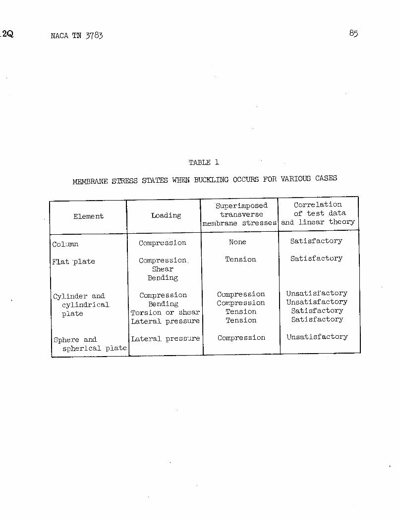
2Q NACAT_ 3783 85
TABLE i
MEMBRANE STRESS STATES WHEN BUCKLING OCCURS FOR VARIOUS CASES
Superimposed CorrelationElement Loading transverse of test data
membrane stresses and linear theory
Column Compression None Satisfactory
Flatplate Compression Tension SatisfactoryShear
Bending
Cylinder and Compression Compression Unsatisfactorycylindrical Bending Compression Unsatisfactory
plate Torsion or shear Tension Satisfactory_Lateral pressure Tension Satisfactory
Sphere and Lateral pressure Compression Unsatisfactoryspherical plate
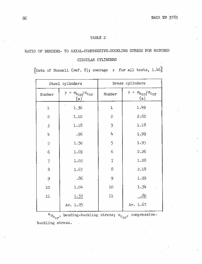
86 NACA TN 3783
TABLE 2
RATIO OF BENDING- TO AXIAL-COMPRESSIVE-BUCKLING STRESS FOR MATCHED
CIRCTU/kR CYLINDERS
[Data of Donnell (ref. 8); average 7 for all tests, 1.46]
Steel cylinders Brass cylinders
Number 7 = _bcr/_Ccr Number 7 = _bcr/_Cc r(a) (a)
i i. 36 i i.49
s l.lo s s.62
9 i.i8 3 i.i8
4 .96 4 1.99
5 i.5o 5 i.95
6 1.69 6 2.26
7 1.02 7 1.28
8 i.67 8 2.18
9 .86 9 i.29
io 1.04 io i.34
ii i. 37 ll .80
Av. 1.25 Av. 1.67
a_bcr_ bending-buckling stress; _Ccr_ compressive-
buckling stress.

NACA TN 3783 87
DATA FOR CIRCULAR-ARC SECTIONS IN BENDING
_ii specimens were fabricated from 7075-T6 aluminum
alloy and were 120 in. long_
Specimen H/t H/c r/t ZL gexp/gemp
i 3-3 0.04 667 146 i.43
2 7.6 .08 333 293 i.16
3 io.5 .io 25o 39o 1.15
TABLE4
GRADIENT FACTORS FOR CIRCULAR-ARC SECTIONS
CI C2Y = CI/C 2
(from table 3) (from fig. 7,using U = 0.00015)
o.4o8 o.27o 1.51
•331 .250 1.32
.329 .395 .83
.)/

88 NACA TN 3783
ABLE5
INTERACTION EQUATIONS FOR CIRCULAR CYLINDERS
UNDER COMBINED LOADINGS
Loading Interaction Applicable rangeequation (a)
_xial compression Rc + Rb = i All values of ZL, all edgeand bending restraints
i il
Using theoretical _cr and Tcr ,
ZL < i, SS
ZL < 5, C
Axial compression Rc + Rt2 = iand torsion Using empirical _cr and Tcr ,
1 < ZL < 7.7(r/t) 2, SS
5 < ZL < 7.7(r/t) 2, C
Using theoretical Tcr ,
Axial tension and 0.4R c + Rt = I -i < R c < 0
torsion 30 < ZL < 7.7(r/t) 2
both SS and C
Bending and Rb 1.5 + Rt2 = i All values of ZL, all edgetorsion restraints
aSS, simply supported edges; C, clamped edges.

NACA¢N 3783 89
TABLE6
PLATE DIMENSIONS FOR TEST SPECIMENS OF
VARIOUS INVESTIGATORS
[All dimensions are in inche_
Cox and Crate and JacksonSchuette
Dimens ion Clenshaw Levin and Hall
(ref. 60) (ref. 61) (ref. 62) (ref. 65)
L 24 24 18 3 to 25
r 18, 36, _ 11.4 to 121 24, 48, _ 3.25 to 21and
b 4, 6, 8, I0, a8.7 3 to 7 3.2 to 2612
t 0.018 to 0.067 0.065 to 0.128 0.018 to 0.039 0.015 to 0.248
aAverage value.

TABLE7
IMP RFEC IOPm RS FOR SPECI S
OF KAPLAN AND FUNG (ref. 75)
Specimen r/t _cr/_cl d/t aO Uo
i 316 0.464 635 0. 249 2.17 × 10-42 519 •425 645 .446 3-783 309 •439 635 •358 3.224 219 •573 640 •592 6.25
5 211 .414 635 •565 3.95
6 628 •708 i,210 •050 •177 602 •565 i,210 •156 •55
8 517 •521 i,230 .184 •759 384 •587 i,160 .118 •65
i0 382 •517 i,250 •176 •99
ii 572 .448 i,250 .386 2.5012 851 .262 2,050 •292 .8413 691 •369 2,000 •354 i. 3414 752 •315 2,050 •325 i.2415 615 •556 i,950 .694 5-15
16 591 .402 i,950 .292 i.4417 621 •332 2,220 .624 4.4518 207 .404 635 •403 4.3919 186 .442 655 •156 i.60
20 549 •654 J i,160 .082 •32
21 559 •556 i,190 .114 •6722 722 •379 2,000 •325 i.17
23 606 •554 i,9_0 .148 •71
a2.00
aAverage value.

o oo
/OJ / o
d' j/d _ o _ "
t#
/ ) IIIl)llJ I I IIIlllI0 I(:_ IO s I0 _ lO s I I0 lO t 10 3 I0 _ lO s
z,
(a) Axial compression. (b) Torsion.
J
I
I IO I0e I0a I0_ I0a
(c) External radial pressure.
Figure i.- Comparison of linear buckling theory and test data for circular cylinders under axialcompression_ torsion_ and external radial pressure.

CC YLII_ER
INITIAL IMPERFECTION =I
oWAVE DEPTH
THICKNESS
Figure 2.- Buckling-stress ratio as a function of buckle wave depth for axially compressedcolumns_ plates_ and cylinders.

Q NACA T_ 3783 93
A
AVERAGE B •S TRESS
C
D
S TRAIN
ENERGY t
F B,C
END ,,_HORTEIVING
(a) Rigid testing machine.
Figure 3.- Theoretical behavior of axially compressed circular cylinderin rigid and dead-weight testing machines according to theory of Tsien(ref. 12).
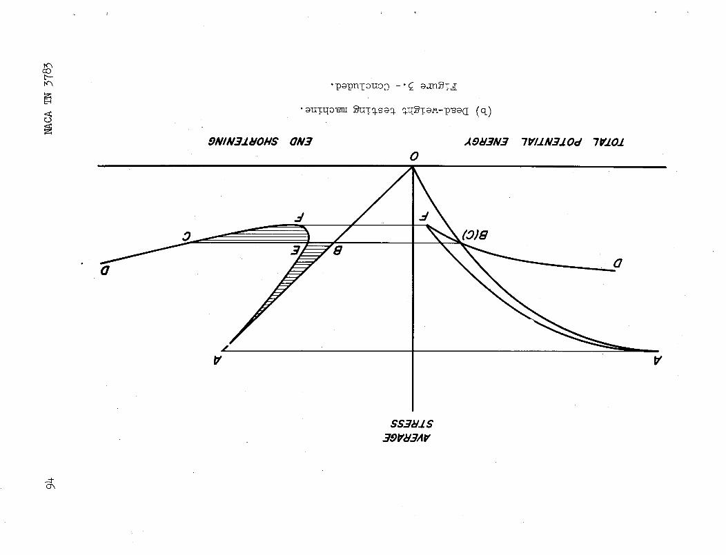
B_cO
"_uTtlo_J__TO.S_o. o.tI_T_-p_(l (q)r.D
9NIN..71HOHS ON.] ,,(9_3N.=7 7VI.I.N..7.1.Od 71f.1.01
0
.4
0
• G0

_cA T_ 3783 95
d54LI"
SHOAPT TRANSITION f.ON@
_2E
_-fcylin_er (Z_,r/t,T,h) •
y f 1F-
SHOR T TRANS/7"10N L ON@
= k_2E t 2 b2 (i - Ve2 1/2(b) Curved plate. _cr 12(1-re2) (_) ; Zb : _ )
k = fplate(Zb,r/t,L/r,r/b).
f\
o (FLA T $HA L LOW DEEP
c) Spherical cap. _cr = ; Zd = -- i - Ve2 ;
121l - re2) rt
k = fcap(Zd, r/t,d/r).
Figure 4.- Geometrical parameters and ranges of behavior for cylinders_curved plates_ and spherical caps.
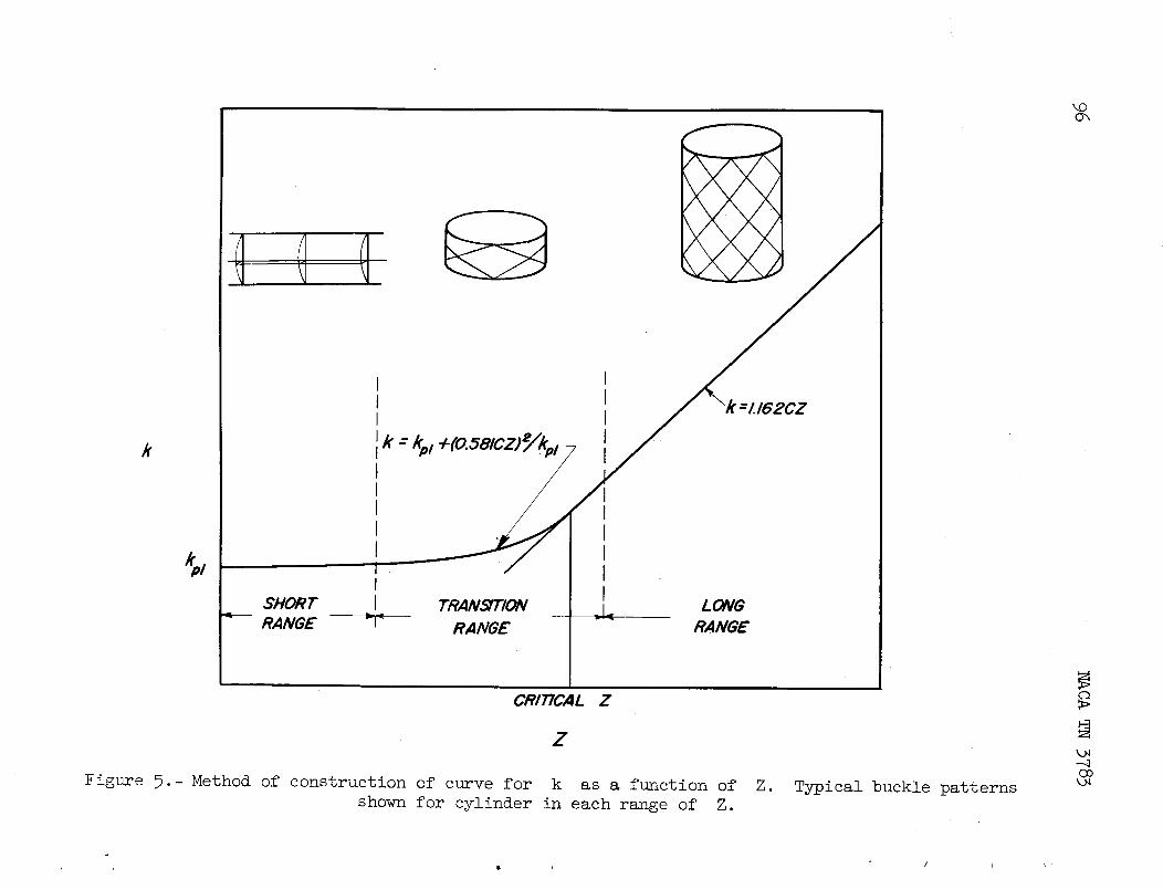
I II II I
Jk - kp_+(o.selcz) Ik ItI
I II I
kpI I IIf I
SHORT I TRANSITION =1_. LONG"-- RANGE =T_ RANGE - -_ RANGE
CRITICAL Z
z
_igure 5.- Method of construction of curve for k as a function of Z. Typical buckle patternsshown for cylinder in each range of Z.

I I I IIIII I I Illlll
II /0 iot J I0• /0" I I I0 I0_
z, z,
(a) r/t = 500. (b) r/t = 750.
//
/d ,/ _ ,d
, _ / '. //o/" 0
/ I [ I Illl/0 /0' I ' ' '""JI A_ p"
z, zL
(c) r/t = 1,000. (d) r/t = 1,250.kO
Figure 6.-Buckling test data and. corresponding empirical curve for clamped axially compressedcircular cylinders.
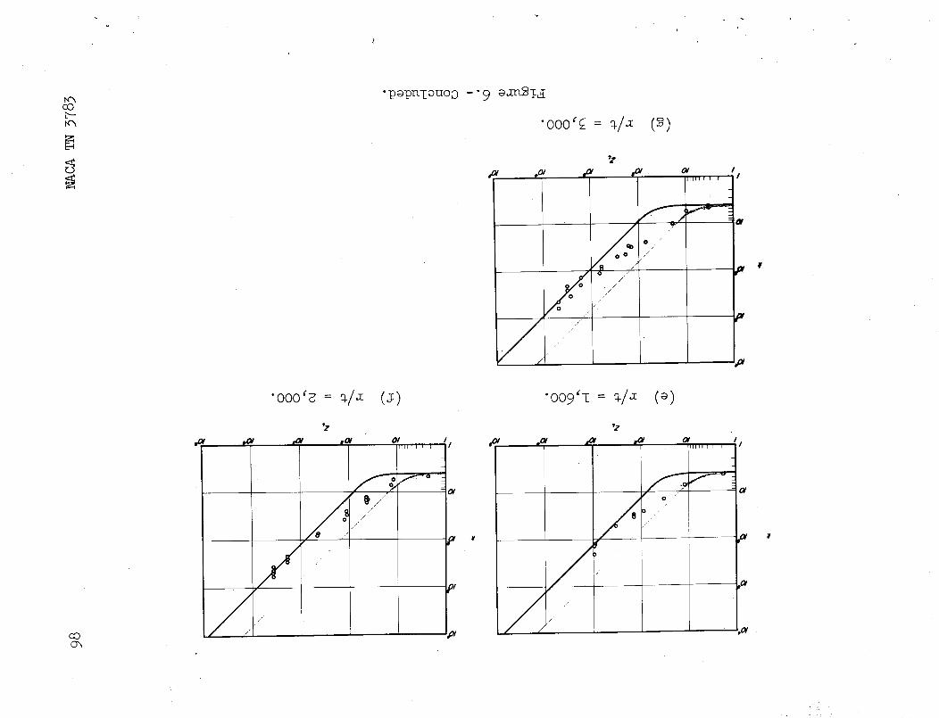
rc_ "p_puTouoo -'9 _,ra_T_cOb--
"ooo'_ = _/_ (_)
d _V O/ IIII_1 I I I #
JA J q
o J/
.J
•ooo'_= _/_ (s) "oo9'I--_/_ (_)
•z "z
.... _ b, rc _ ....... '/ ,_v _, t _........ ,,
OI
CO :V _01
.? "

--0--0=-0-- EMPIRICAL CURVE OF BATDORF,SCHILDCROU_ AND STEIN (ref. 16)
THEORY OF DONNELL AND WAN (ref... 20)
.01I0 t _ a • i0 _ .10a a s s • /0_
r/t
Figure 7.- Modified classical buckling coefficient as a function of r/t for axially compressed _o\Ocylinders.

lO0 NACA TN 3783
/.51 ¥/t 1500 o o Jo
/.01 c o @ I0 0.5 I i i
2.5 II tit. 750
2.0_ o o
1.5 o o o
1.0 n o 0 0.51 , i t i
z.5 [ ,/,._ooo
2.0[ 0 0
1.5 o o 0
1.0 o/ o o o o
.51 I t I t
2.51 r/f - 1230 o
_.0 [ o
/.5 0
1.0 Ca Q 000 0 00
.5 I I I I 0
3.0r/t, 1,600 o
t.5o
_.0o o
/.5
LO 0 0
._ I I I I
_.02"5f .It. _,000 o o o
1.5 0
/.0 0 0 0
.5 A i J
3.5 or/t,, :_000
3.0
t.5
e.o o 6,0 o°1.3
0 o o1.0 ----c n- o
.5 I I I I
I I0 I0 a I0 # I0 _ POs
Figure 8.-Magnification factor for axially compressed cylinders derivedfrom figure 6.

_z
#01 tO! tOI FOI OI _ s I 0
'1'1'1'1'I'1'1 ' I ' _J
I
o,° .o _.= ,0_,.,
° '_,-- '_ h, l_
o_ o "\ \
009_ • oo_ _0_ I l/'J )
ooo'I v \ 0"£og_ 0 \1
oog Q
c_

lO2 _CA TN 3783
.6
/2017-T4 _/ 6161-7"$
o
o rest OArA o .
o
0 _ 30 40 5G30 4O 80
, ksi
(a) Data in plastic range.
1.0 0 _ 4
.8 -T60
.6
.4
°\°2
c
o /o _,o 3o 4,o _ eo _ oo 9o /oo
ksi
(b) Data in yield region.
Figure i0.- Plasticity-reduction factors for axially compressed long
circular cylinders of aluminum alloy. Comparison of test data and
theory using values of C from figure 7.

12 2 co
lO m
0 .2 .4 .6 .8 lO L2 1.4 16 /.8 _-0
O'o.v
Figure ii.- Nondimensional buckling chart for axially compressed long circular cylinders.
_ = (Es/E)I(Et/E)(I - Ve2)/(l - v2)_ 1/2. _°_

_f
c
Figure 12.- Hypothetical buckling behavior of axially compressed circularcylinders in inelastic range.
-qOo

_CA T_ 5785 i05
.6
.5_ THEORY _--
DATA o
//o
.4 /
- I< °.3
_ o/7 if FROM FIG 7 o
i I I I I0 .08 .12 .16 .20
P/r It-gIT/
Figure 13.- Effect of internal pressure on axial-compressive-buckling- _crr
stress of circular cylinders. _cr - Et
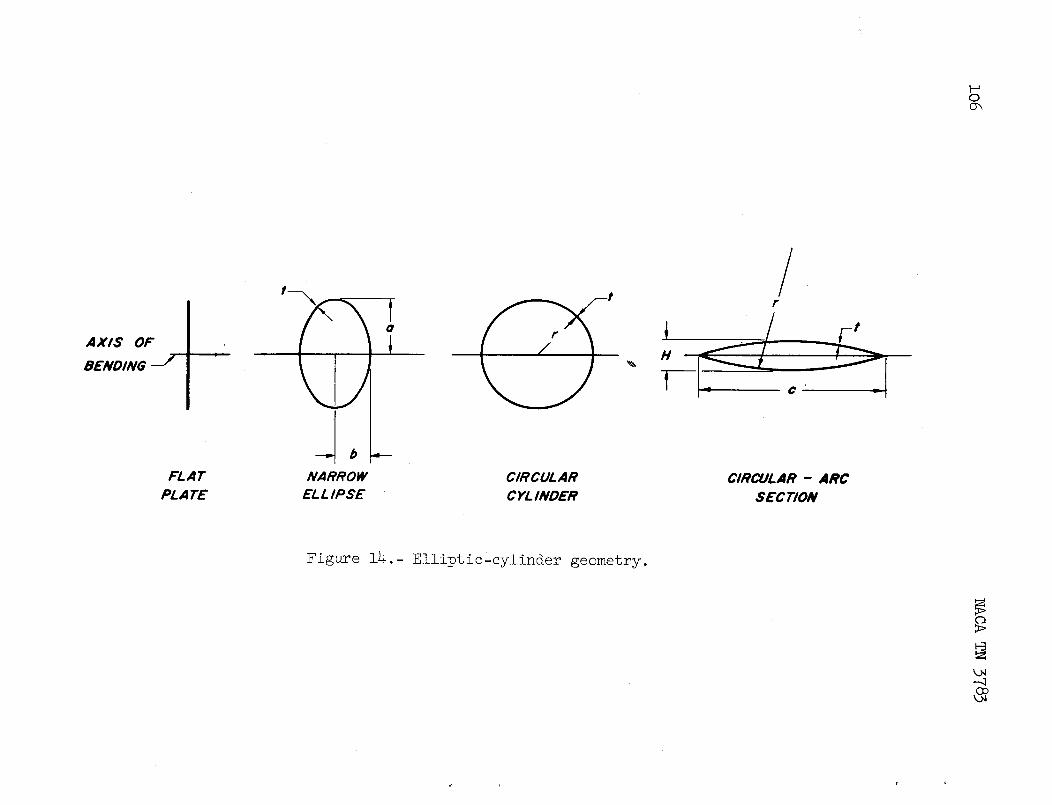
0
!AXIS OF
BENDING --1t ' _
FLAT NARROW CIRCULAR CIRCULAR - ARC
PL ATE EL LIP SE C YL INDER SECTION
Figure 14.- Elliptic-cylinder geometry.
oo
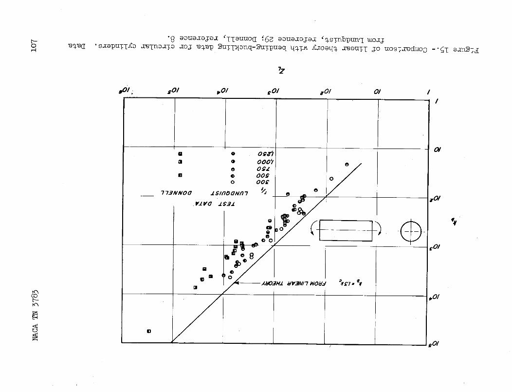
BOI. _01 _01 tOI wOl O1 II
a o o_z'l OIrl • 000'1
in _ 00_ /"
o oo£ o /
' i ,01
" () "_0!
/ _01

0Co
.6
./
.0/I0 I0 • lO s /0_
r/t
(a) Data of Lundquist for Duralumin sheet (ref: 29).Co
Figure 16.- Test data for long circular cylinders in bending.

/..o
_ °
FOR
o a o_X o_o _ 0
0 0o
oi 0
CA TEST DATA OF DONNELL
o STEEL SHIM STOCK 13El BRASS SHIM STOCK
#0 /0 t I0 s I0 4
tit
(b) Data of Donnell (ref. 8).O_O
Figure 16.- Concluded.

ilO NACA TN 3783
.00250
\
---=000t98\_OO02_
.oooL_$
o COMPRESSION"
.00010 - -
DO0062OO /,000 P_,O00
Figure 17.- Test data of Lundquist for long circular cylinders in axialcompression and in bending (refs. 14 and 29).

_q
CURVeFORCb-X30, FORU-O00015
SCATTER BAND
OF LUND_JIST'S
CIRCULAR CYLINDER
Cb .I DATA FOR BENDING _
TEST DATA
LUNDOLIIST HEGKAND BURKE
( ref. 30) (ref. 31)b/o b/o
BENDING ABOUT 0 0.6 [] 0.6?'MINOR AXIS • O.B • 0.50
BENDING ABOUT A 0.67MAdOR AXIS • 0.50
.01 I .I0 I0 e lO s I0 _
r/t
Figure 18.- Test data forlong elliptic cylinders in bending.

5 • /o0
4 F/o (y/O)crj .8
3 .6
7/o - (y/O)cr
2 .4
b/o = 0. 8 6 6 ------_ - .I
A
llill i _ i _ i I U
0 ./ .2 .4 .6 .8 /.0
b/oC_
Figure 19.- Location and magnitude of critical radius of elliptic cylinder.
r
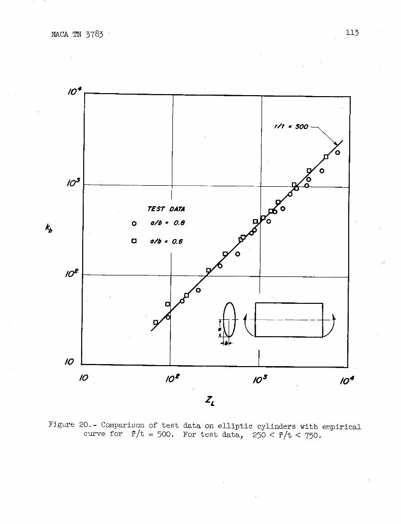
_4
r/t = 500_
/03 i_00 0 0
TEST DATA /
e/b 20.8 J
/o_ / o
o/y O
Z_
Figure 20.- Comparison of test data on elliptic cylinders with empirical
curve for _/t = 500. For test data, 250 < _/t < 750.

L1,°TIC SECTION _-
f
l " "i \ COM_SlON/ \
G I \ j
i !
' ' /A_ /\ I\ I
\ \ 1// ,/ -_ TG/VSlON
-b.,
C/RCL_;>
Figure 21.- Location o£ critical radius of Curvature for elliptic cylinders in bending.
co
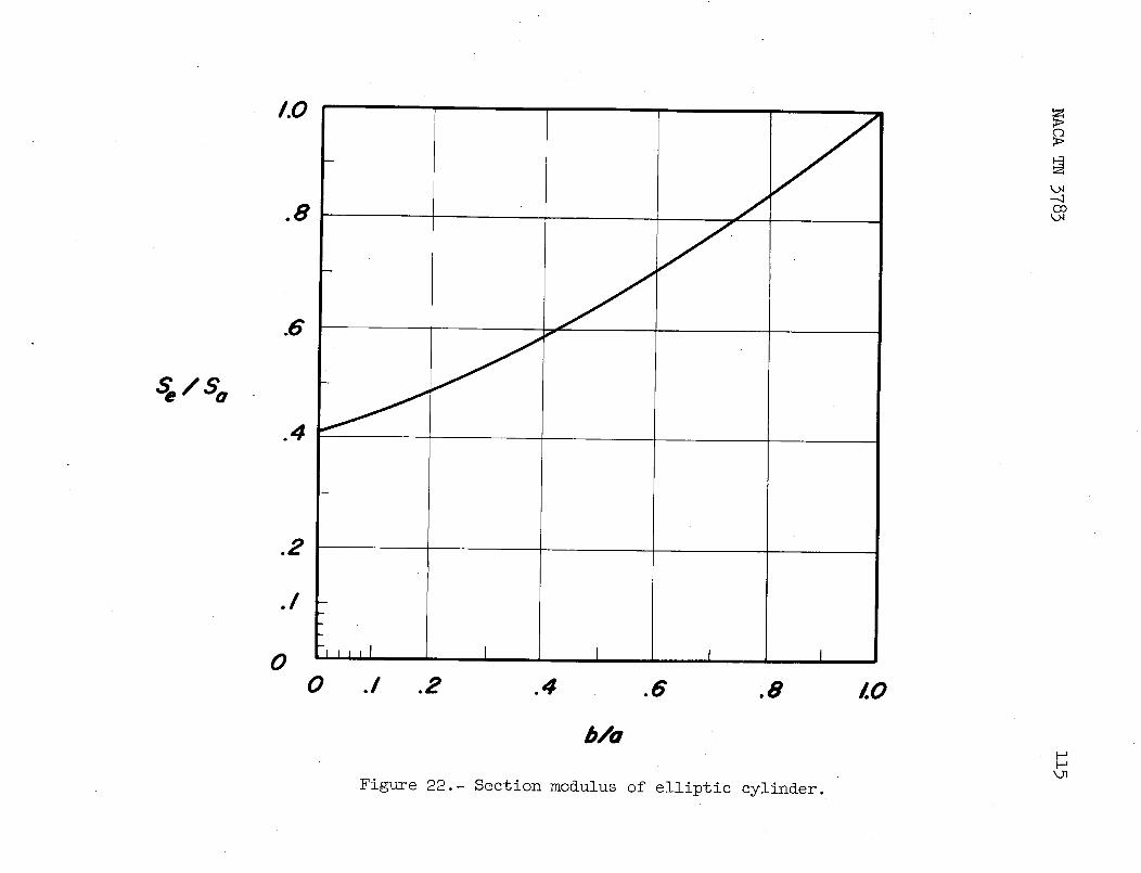
o2 • ii
.1
7,,t,l l i I i00 ./ .2 .4 .6 ,8 /.0
b/o
1Figt_re 22.- Section modulus of elliptic cylinder.

i16 _cA TN 3783
.olr
Figure 23.- Method for determining location and magnitude of criticalradius of curvature.

50 _
(3o
6o6/-r6 sTREss-sre_ve CURVE-_.
40 __--_ /_°'b ----'_'_-o" = r (o-/_7)
3O
0",
k#12O
I0
0 =
[ I I I Io _o /oo o'l'r/, /so aooI I I ksi I J
0 .010 .OtO .030 .040
Figure 24.- Stress-strain curve for 6061-T6 aluminum alloy and derived curve of _ as a functionof
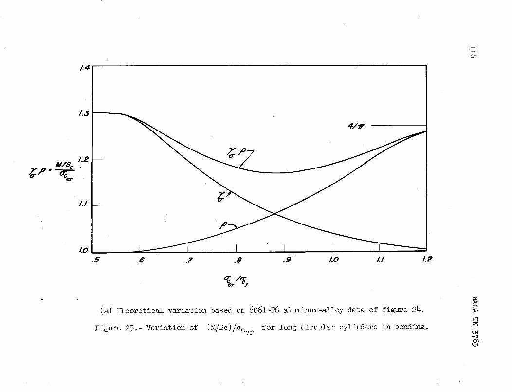
Oo
L4
LI
_.o I I I 1 I.5 .6 .7 .8 .9 LO LI 1.2
(a) Theoretical variation based on 6061-T6 aluminum-alloy data of figure 24.
Figure 25.- Variation of (M/Sc)/c_ce r for long circular cylinders in bending.---.1
k.N

1.4 r
TEST DATA (DO
0 20/7- T4
0 7075- T6
L3
T/40
N/se 1.2 o_ I
1.1 / _\
/,1.0
.9 r.O I.I 1.2 1.3 1.4 1.5 L6
(b) Experimental variation.
Figure 25.- Concluded. kO

J
jk, I_ SOLUT/ONOF __
BATDORF, STEIN_ AND SCHILDCROUT _ wK(_'_
S _ SOURCE _Te_IA_L
o Lu_oulsr(eEF.38J_oI_-r4
/0-___ . Do_L, (eEr.6J B_._- _ 0 _LL (REE 6) STEEL
5 1
I _ MOORE AND 2024-T31
W_COA T(REF.41)
v BRIDGET,JEROME, ST_L-- AND VOSSELLER
(REF. 50)
r J i J i I,lll_lllhl, I JI 2 5 I0 I0" I0" I0" lO s
CI
Figure 26.- Comparison of test data and theory for simply supported circuler cylinders in torsion.
Tcr 12(_ - _e2) _ ZL = rt " _C°

NACA TN 3783 121
/
9/- `
E]v
[]
600
*' _ °04oo _
2oo X___
o 2poo 4,ooo _ooo __oo _qooo
z,
Figure 27.- Enlargement of a section of figure 26 on a linear scale.

/0
7"/_r
--= _ INITIAL IMPERFECTION=
Figure 28.- Buckling stress as a function of buckle wave depth for cir-
cular cylinders in torsion. Curve taken from test data.
k.N
k.N
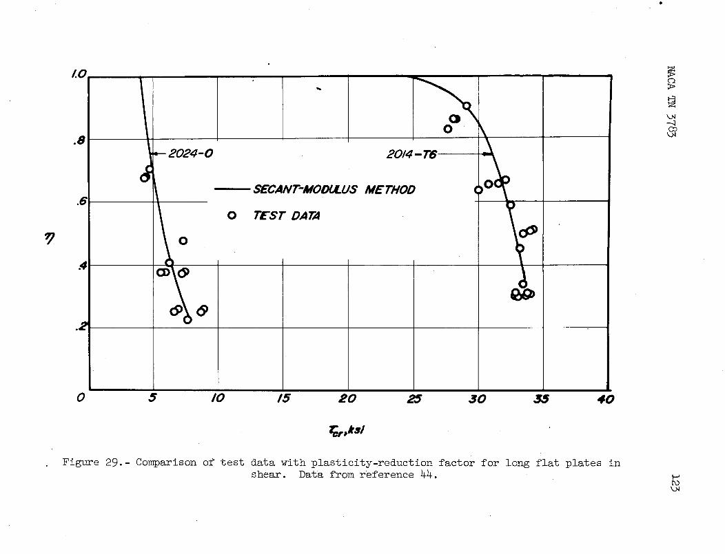
o
/.o ,,,
k)4
0 --.a(2o
_ 2024-0 2014 - T$
dSEC.4NT-MOOULU,,,° METHOD (
0 TEST DATA
o.4
0.2
1
0 5 I0 15 20 25 30 _ 40
Figure 29.- Comparison of test data with plasticity.reduction factor for long flat plates inshear. Data from reference 44.
PO

124 _cA TN 3783
/O
_ 2017- T4
6 o_E- MOLY" )0 rEST DATA ('
2
0 /0 20 30 40 _0 60
_r, ksi
/.0
8 0 _7075-T6
e
6
,4
030 35 40 4_ 50
_r' kS/
Figure 30.- Comparison of test data with theoretical plasticity-reduction
factor for long cylinders in torsion.
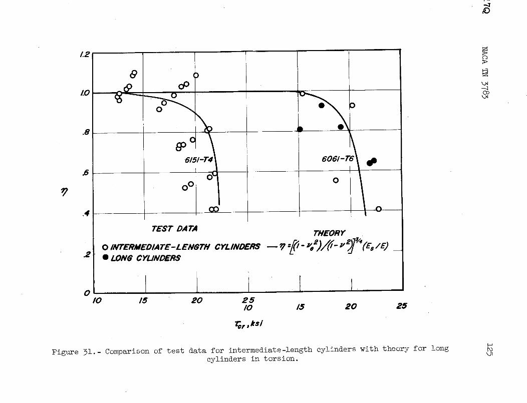
r'---
_D
/.2 .....
x.o @ oO
_._ ,, -_
@c
mm- eo2l- @_ o_
_ o°!
.4 _ i 0I
TEST DATATHEORY
2 *LoM_cru_mns
0/0 15 20 25
I0 15 20 25
for, ks/
Figure 31. - Comparison of test data for intermediate-lemgth cylinders with theory for long _
cylinders in torsion.

126 NACA TN 3783

NACA TN 3783 127
I0
9
8
FROM .INTERACT/ON "_
7 OUAT/ON
rcr, kSi
4
3
2
0 I 2 3 4 5 6 7 8 9 I0
P-Porr.O , psi
Figure 33-- Effect of internal pressure on torsional-buckling stress oflong cylinders. Test results are from reference 43.
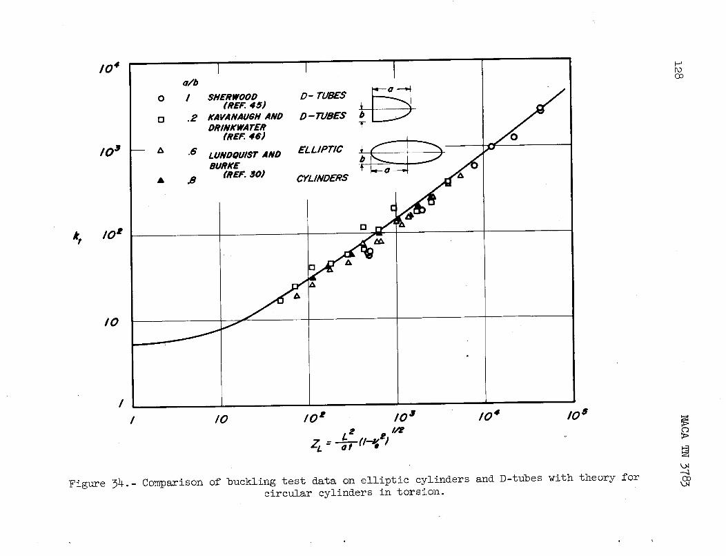
104 I _a/b
I o I SHERWOOD D- TUBES --__-_ /I _REP.4S; _ ojI r_ ,2 KAVANAUBH AND D-TUBES b ._,,JI DRINKWATER T
1 (REr. 46)
I BURKE u__..__.__ ._
• .8 reEF, 30) CYLINDERS _ _,-0 --..__Q
!
I I0 I0 e I0 a 10 4 I0 a
Lt t I/_zc=.-._r1_ ;
k.=,xl
Figure 34.- Comparison of buckling test data on elliptic cylinders and D-tubes with theory forcircular cylinders in torsion.

(r/t) l__vee - __0o
_ OF
1(2 BATDORF--_ "J
_ o DAtAoFsru._fREF..4Z)
I
I I0 lO t 103 1(24 lO s
z_
(a) Buckling under external radial pressure. _cr =
Figure 35,- Comparison of test data with theory for buckling of circular cylinders.

/0 2
[]
THEORY OF TEST DATA
I0 BATDORF 0 WINDENBERG AND
(REF. 3) 0 TRILLING (RE/='. 48)
El STORM (RE/:'. 47)
I I0 l0 t 10 3 10 4 lOS (
V
(b) Buckling under extermal hydrostatic pressure. _cr = 12 (i - Ve2) __<Do
Figure }5.- Concluded.
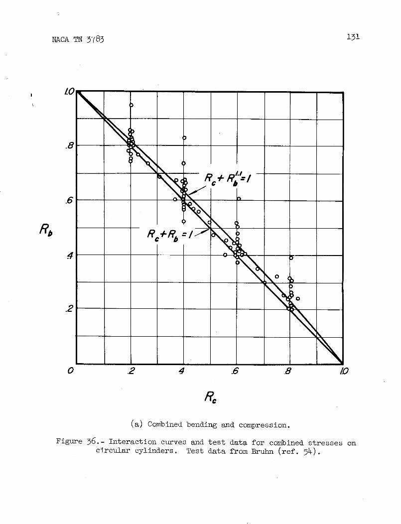
4
_o
_o.2
0 .2 .4 .6 .8 /.0
(a) Combined bending and compression.
Figure 36.- Interaction curves and test data for combined stresses on
circular cylinders. Test data from Bruhn (ref. 54).
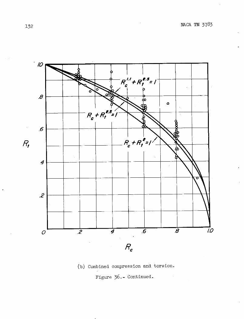
132 NACA TN 3783
,: _l.l+Re.s /
e ���=i
R, _+
10 .2 .4 .6 .8 LO
R_
(b) Combined compression and torsion.
Figure 36.- Continued.

R.
(c) Combined torsion and bending.
Figure 36.- Concluded.

134 NACA TN 3783
i i I i i I I.
I.O [ L/r : _._4 L/r,/._4 _ L/r 1.5o
\ , -.,\\ . \ "_•__, ._ _ \ _ , _ \ "-._
._ ,'\ __\ _ _ \' \_ _ \ \\ _•,_ 't e_, .,_ o ,,, .e_ ._ _ _ _o_ ._ ._ zI o'
o .e .,_ .e .e /.o o .z .,_ .e .e /.o o .e ._ .e ._ /.o
eb
(a) i< L/r < 1.5.
Figure 37.- Interaction curves for combined compression_ bending., andtorsion on circular cylinders of different proportions.

NACA TN 3783 135
1 l i , , l _ 1 i
/.o, ._,,,_ e/t= 46o _".. - r/t .-_6o! _._ l r/, : eoo-
.s C._\ . .....
\'\" , _\ \, . _\!',
' I?o_ =,I ; "k .' o, - • ' Io,
\ \ "x \ _ \ \ x ,, \)\
o ._ ._ .s .s /.o o .s ._ .s .s /.o o .s ._ .s .s Lo
(b) 2 < T,/r < _.
Figure 37.- Concluded.

/,000 ._ PO_
(,_. oO (ReF.60
I00 tO(
/
I
/o zb Ioo i,ooo /o zb 'oo _ooo
/,ooo / _ooo
cox_o CLe_S_M _ SC_UET_C_er.6o) (_¢r.6s)
o
I00 e ° I000 o
o
I0 _ I0 /
o oo
/ I
/ /o z, /oo _ooo / /o zb too _ooo
(a) Comparison of test data with linear theory.
Figure 38.- Comparison of test data with theory for axially compressed
curved plates.
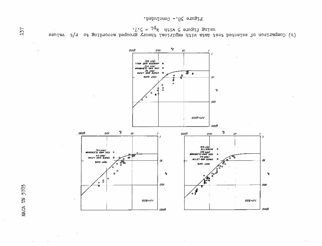
•p_pn-[°u°o -'9_ _za_Tal
san-[_A o./_[ o_ _uTp_ooo_ padno_ -g_oa_Io.-[_oT=ydm_ _Io.T__o._p _sao. pao.oa-[asj.o uosT_duloo (q)
oodl oo/. qz o�I
77¥N ONV NO$_V# A
6o9ya_)MYHS'I¢.,7?O ONU' XO0 o
h
1 Ac A a¥
00/
ooo_*_/./
ood/
ooo'/ oo/ *z o/ ood/ oo/ *z o/I /
_'HSN._7,00NV XO3 o _s 1"09y.U¥)
- --/o,_ ° - __ So-
_ 001 001
ooch ooo"I
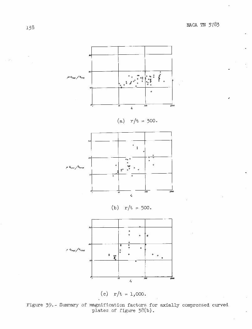
z98 NACA TN 3783
£_ oo
.... Oo o/_-k_.p_p o o oO
o d °°o o Oo°_ _oo_o o oo o
0
o
.<
0 /0 /GO _0
(a) r/t = 300.
o
ooo
o
2,o vOo o oo
kaexp/kcen_p o o_ o o/_= oo o o o_ on
t(o o
/o /00 _ovJO
(b) r/t = 500.
o
o o 0
otc _ o o
o o
/_"kCexp/kCernp oo
oo o o o
o
1o leo t,oooZo
(c) r/t = 1,000.
Figure 39.- Summary of magnification factors for axially compressed curvedplates of figure 38(b).

COXANDCLENSHAW--_
0I I0 !0 e lO3
Figure 40.- Ranges of magnification factors for test data of figure 38(a). Data from Crate andLevine, reference 61; Cox and Clenshaw, reference 60; Jackson and Hall, reference 62; andSchuette, reference 65. _o

I0 o
C ./
Figure 41.- Theoretical variation of C as a function of r/t for U = 0.000092 and comparison
with elastic data Of Schuette (ref. 65) for axially compressed curved plates.
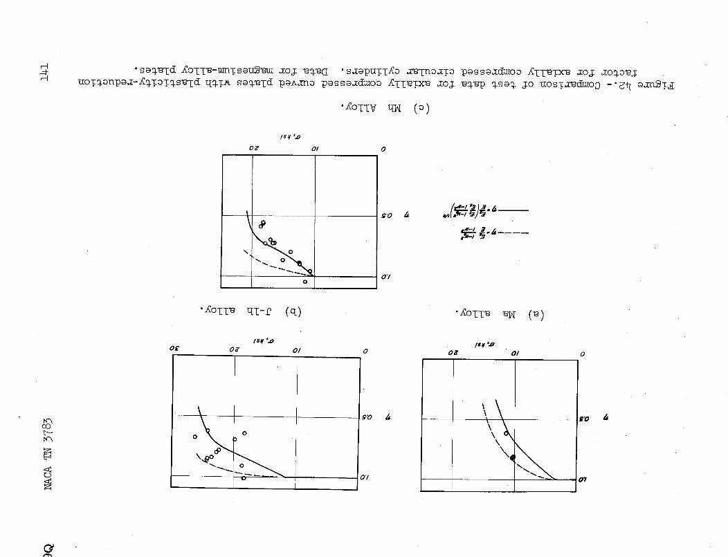
_-4
UOT_OnP@_--_TOT_S_IClLI_T_s_-[d paAm-mop_ss_du_oo _Tl_TX_e_oj _p _s@_ Jo UOSTXeClmoo-'_i7 _;EL_T,_
_oz_v _ (o)
IS¥'..o
o_ Ol o
o£ oz Ol o o_ Ol oI
i
co \)o \o
- 07
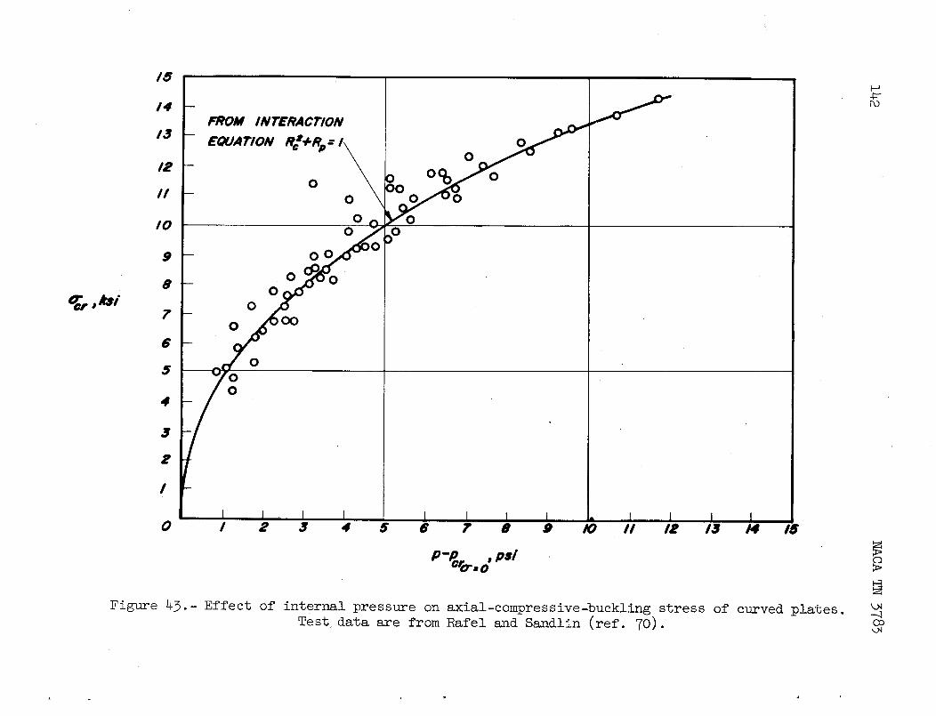
/6
14FROM INTERACT�ON
/3
oIE
o o0 o_ o// 0
o/0 o
9 o
o o8 oOccr, /tsi 0
70
6
05
04
3
E
/
o , _ • • s • , • 9 m ,, ,t ,s . ,s
P-PO,o..o.'/ _.
Figure 43.- Effect of internal pressure on axial-compressive-buckling stress of curved plates • __
Test data are from Rafel and Sandlin (ref. 70) oo
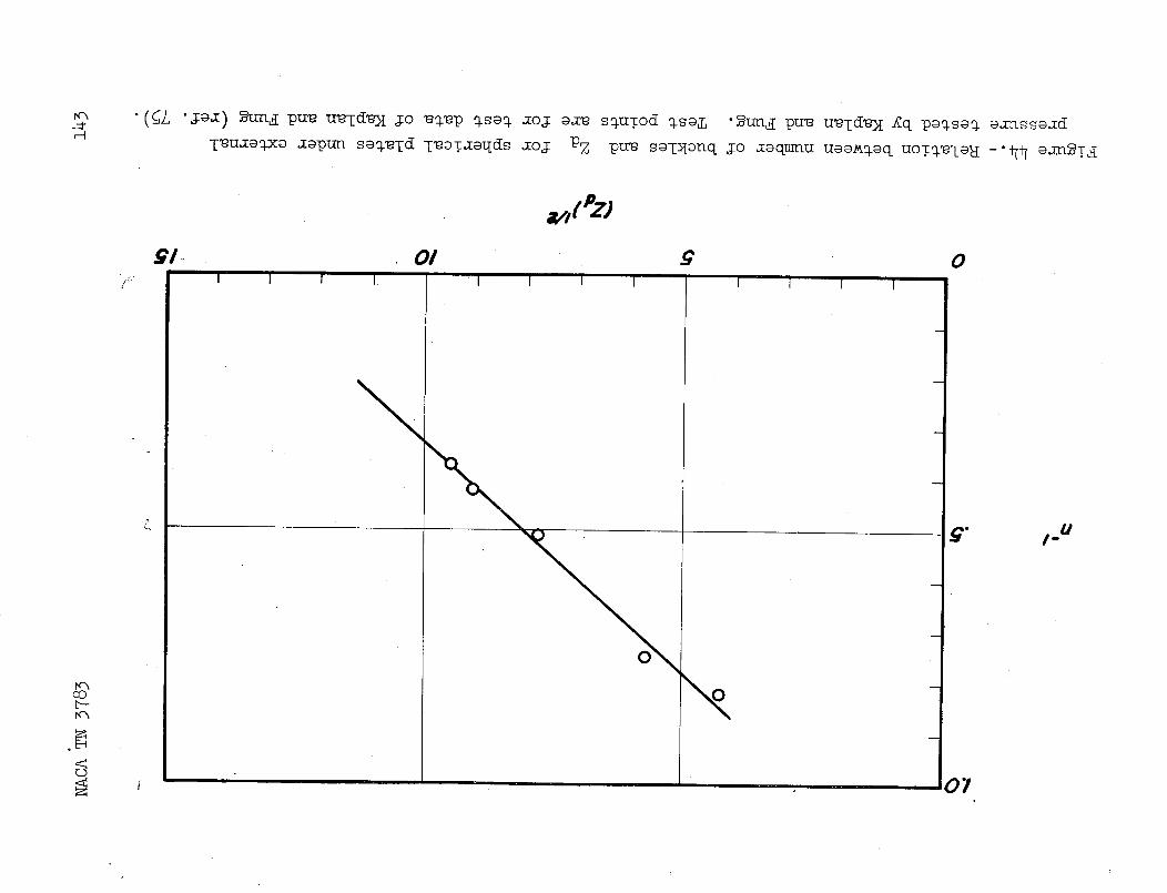
g. _,_u

144 NACA TN_3783
_.0 "'"
. i
0 .10 .tO .30 .40
Lr/!
Figure 45.- Empirical curve fitted through spherical-plate test data of
Kaplan and Fung (from ref. 75) to obtain relation between _cr/_cland Uor/t. _cl = 0.6Et/r.

•uosT_dwoo _oj u__oqs (_T -ja=) uays,T,jo pu_ (SL "Ja_) _tra,_pu_ u_Td_)I
_H
pOl _ • eO/ $ Z • OI 9 _ O�I0"
I _0"
N31S.L 0
9Nl'l.d ONV NIT'TdV_ 0
VdI_'0 d S3d gO
.
9
|I ° on
co
r_ 9"0 = 0 7V,91S,_V7,9
' 07

146 NACA TN 3783
lINEAR /
THEORY _ / D
,ZT/'[],o,. . ./
n #_SlEIV£REF.I_
I r
I I0 I0 e I0s
z_
Figure 47.- Test data for spherical plates under external pressure com-
kp_2_ 2
_e_t_em_,_o_t_oor,._cr--_(_::o_)(_)•

• OI #01 OI jr O! • OI OI II /
A O$7 • _J_'lC3 I_'1 D ££ "1
o • oo7 A _,1"10 • 00"1-r_0053_ iWTONV,q .LVOO$3d_l N_7ONII_r
E_

v oo'£rl Go' rl M;'I
o oo "/ o 007O.LI_VlHO NIA._"IONWNH/'I_f q/_ OJ./_I_IHONIA._'ION_ NNfl_f f/'_
eOI _ EOI .
CO._.fi-

0Q NACA TN 3783 149
,d :'_
/.o\/.5
m\
S '/o_ _ .
__- I_'=-_I 1_- I t o
I/ ' el , I , l,sl,l,l,lJl,lO /0t I03
Zb
(a) Long simply supported plates.
Figure 49.- Shear buckling coefficients for various curved plates.
= ks_2E b2 (i- Ve2) I/2
_cr 12(_- 7e2)(t) 2_ _ = r-_ "
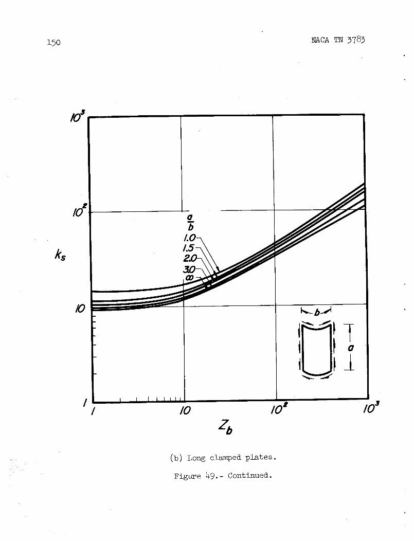
15o _cA _ 3783
/ i i I I IIIII /0 lO t 103
_ (b) Long clamped plates.
Figure 49.- Continued.
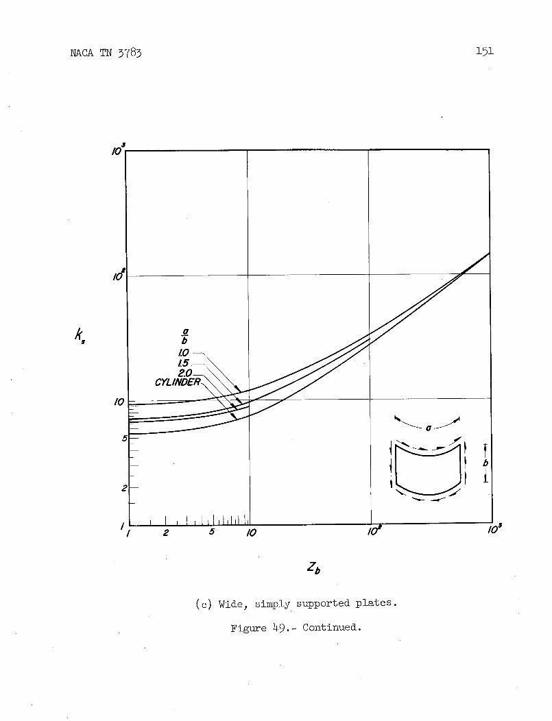
NACA TN 3783 151
4
LO15.--2.0--
CYLINDE_
5--
- I' I _
, I , I , I,l,l,lJl,t,I I z 'J /0 I0 t lOS
z_
(c) Wide, simply supportedplates.
Figure 49.- Continued.
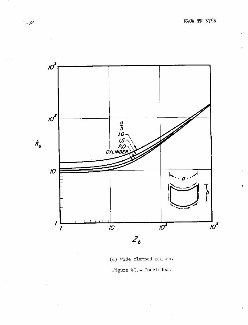
152 NACA TN 3783
° f1.O-k
C
I I I I I III
I I0 l0 t 103
z.
(d) Wide clamped plates.
Figure 49.- Concluded.

1Q NACA _ 3783 153
I0
FROM INTERACTION
.. 9 EOUAT/ON _t+_ 0 00
8 0 0 0
0 000 0z o Ooo
oe6
0
Tcr,ks/ 5 0
4 0
3
I
I I I i I I T0 I 2 3 4 5 6 ? 8 9 I0
p--Pcrr. ° ,psi
Figure 50.- Effect of internalpressure on buckling of curvedplates inshear. Test data from Rafel and Sandlin (ref.70).

154 _cA _ 3783D
O
o ( R_)o,p / o l&),,_p I
(a) ba = 1.33; Zb = 63 - 183. (b) b_ = i; Zb = 61 - 191.
II0
0 I '
i I I I I I I I I
0 / 0 /CRc).x, (_c).x,
a
_a= 1.5; Zb = 27 - 85 (d) b(°) b " - = 3; % = 11 - 21.
Figure 51.- Comparison of test data with parabolic interaction curvesfor simply supported_ curved plates under combined shear and axialcompression.
NACA - Langley Field, Va.