handbook of typical school design 2 · pdf filehandbook of typical school design 2 classroom...
TRANSCRIPT
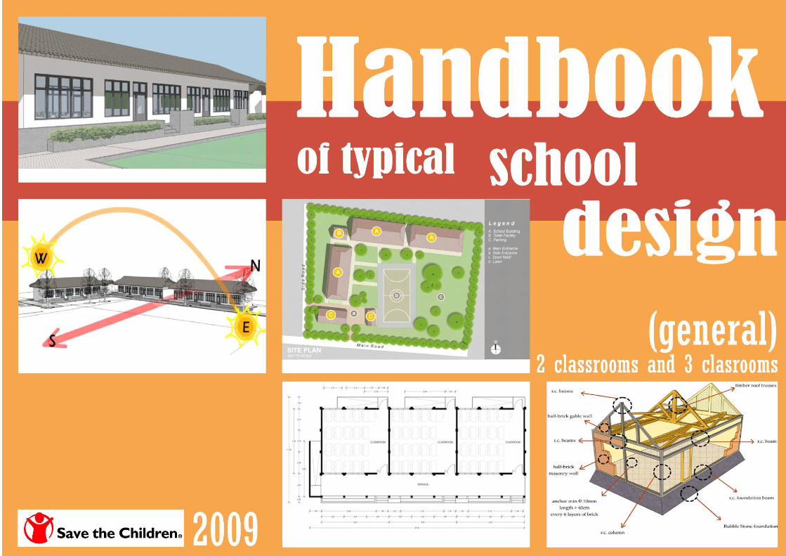
HANDBOOK OF TYPICAL SCHOOL DESIGN
(GENERAL)
2 CLASSROOMS AND 3 CLASSROOMS
Hari Darshan Shrestha
Krishna S. Pribadi
Dyah Kusumastuti
Edwin Lim
Mission of Save the Children
To create lasting, positive change in the lives of children in need
Vision of Save the Children
A world in which every child is ensured the right to survival, protection, development and participation as set forth in the United Nations Convention
on the Right of Children
This book is developed by Save the Children, Construction Quality & Technical Assistance (CQTA)
in collaboration with
Center for Disaster Mitigation - Institute of Technology Bandung (CDM –ITB)


Handbook of Typical School Design 2 Classroom and 3 Classroom
i
PREFACE
Schools are institutions providing an education as well as a common place for community gatherings and meetings. They should be models in providing examples of quality education and the enhancement of the environment & physical facilities. Schools not only provide opportunities for formal education, but also for social development and personal growth.
Despite this, there are millions of schools around the world that are unsafe. There is an urgent need to create greater awareness of safer school construction in new schools, while at the same time making sure that the existing school buildings are safe. This can be done through the implementation of general practices of safe school construction and the retrofitting of existing school buildings.
Creating a culture of safe school construction is possible and need not be as complicated as some may seem. It can be implemented simply by establishing standards of design and construction of school buildings, developing a local building code and ensuring that the code and standards are met. The challenge is the thousands of unsafe existing school buildings around the globe where millions of children are at risk. Recent disasters such as the earthquake in Pakistan and China, the cyclone in Bangladesh and the infamous hurricane Katrina in the USA have caused the destruction of thousands of schools and with them the lives of many students and teachers. This shows the urgent need to make schools safer for everyone.
Save the Children initiated the creation of safe and child friendly school construction. Save the Children is conducting workshops and trainings as well as developing guidelines and manuals to support this initiative.
These documents are based on best practices in Indonesia, the most seismic prone country in the world. We believe these resources could be useful for other countries facing similar challenges as well as other organizations working on building the capacities of local authorities to effectively implement safe and child friendly school buildings.
We would like to thank Dr. Krishna Pribadi, Dr. Dyah Kusumastuti and Mr. Edwin Lim from the Center for Disaster Mitigation - Institute of Technology Bandung, and
Mr. Hari Darshan Shrestha for their contributions on the development of this document.
Mike Novell
AVP, Asia Area office
Save the Children
Handbook of Typical School Design 2 Classroom and 3 Classroom
ii
CONTENTS
PREFACE i CONTENTS ii LIST OF FIGURES iv 1 Introduction 1 2 Aspects in School Building Design 2 2.1 Architectural Aspects in School Building Designs 2 2.1.1 Location 2 2.1.2 Building Layout 3 2.2 Infrastructures and Facilities Aspects in School Building Designs 5 2.2.1 Facilities 5 2.2.2 Drainage System 9 2.2.3 Road and Accessibility 10 2.2.4 Thermal Comfort 11 2.2.5 Lightings 12 2.2.6 Noise Control 13 2.2.7 Access for Handicapped 13 2.2.8 Building's Material 14 2.3 Structural Aspect in School Building Designs 16 2.3.1 Basics of Earthquake Resistant Building 16 2.3.2 Site Location 16 2.3.3 Building's Layout 17 2.3.4 Structural Requirements 18 2.3.5 Technical Specification of Materials 19 2.3.6 Analysis and Design of the Structure 19 2.3.7 Design Notes 19

Handbook of Typical School Design 2 Classroom and 3 Classroom
iii
3 Typical Design of 2 Rooms School Building 20 3.1 Architectural Drawings 20 3.2 Structural Drawings 24 3.3 Lighting and Water Sanitation 46 3.4 Bill of Quantities 50 4 Typical Design of 3 Rooms School Building 55 4.1 Architectural Drawings 55 4.2 Structural Drawings 59 4.3 Lighting and Water Sanitation 81 4.4 Bill of Quantities 85 5 Technical Specification 90 6 Closure 98 REFERENCES
Handbook of Typical School Design 2 Classroom and 3 Classroom
iv
LIST OF FIGURES
Figure 1 School's Siteplan 3 Figure 2 Building's Orientation 3 Figure 3 School Site's Zoning (left), Massing Configuration “L” Shaped Building Arrangement (middle), and Massing Configuration: 4 Solid-Void Assosiation (right) Figure 4 Set Back as Buffer Area 5 Figure 5 School's Ground Plan 6 Figure 6 Classroom-Block Plan (left) and Classroom-Block Longitudinal Section (right) 7 Figure 7 Classroom-Block Lateral Section 7 Figure 8 Toilet Plan and Toilet Section 8 Figure 9 Hand-washing Station 8 Figure 10 Closed Drainage System 9 Figure 11 Rain Water Handling Concept (left), Rain Water Harvesting Concept Illustration (middle), Schematic: Site’s Drainage system (right) 9 Figure 12 School's Accessibility (left), Non-Asphalt/Concrete Material Selection for Road Cover (middle and right) 10 Figure 13 Schematic: Air Flow Within Building 11 Figure 14 Wall Openings in Classroom Block (left) and Various Sun-Shading Devices (Pergolas, Blinds, Shutters) 12 (source: http://www.gawler.sa.gov.au/webdata/resources/images/Shading.jpg)(right) Figure 15 Classroom Lighting and Electrical Plan (left) and Classroom Interior Illustration (right) 13 Figure 16 Ramps and Emergency Access From Classroom (left) and Ramps and Emergency Exit Area (right) 14 Figure 17 Some Alternatives for Building Material Selection 15 Figure 18 Site Location 17 Figure 19 Building’s Configuration 17 Figure 20 Structural Requirements 18

Handbook of Typical School Design 2 Classroom and 3 Classroom
1
1. INTRODUCTION
Indonesia is located in an area that is very vulnerable to earthquake hazards. Geologically, Indonesia is located at the intersection of four earth-plates. Those are
Eurasian plate, Indo-Australia Plate, Pacific Plate and Philippine Sea Plate. Sumatra Island, Java Island, Bali, Nusa Tenggara, Sulawesi, Maluku, Papua, and Borneo
are some of the islands located near the intersection lines. Collision happened on the intersection of these plates often triggers tectonic earthquakes.
Recent earthquakes in Indonesia have caused major economic losses and fatalities/injuries due to damages on structures, including school building. In Indonesia,
most of school buildings, the majority were built in the 1970s and 1980s, can be considered as non-engineered buildings due to very little or no involvement from
engineers during design and construction stages. However, considering the function and usage of the facilities, school building should be considered as engineered
building where the design and construction should be appropriate with engineering criteria from applicable building codes.
Unfortunately proper consultations from an engineer for design and construction of school buildings may be hampered due to financial aspects and other hindrances
(time, distance, etc), especially for the remote areas. Thus, a manual or guideline can be seen as a viable solution to transfer knowledge and experience on building
a school building based on design criteria and specifications from building codes. The development of this guideline on typical design of simple earthquake resistant
school buildings is intended to assist all parties (owner, constructor, and school community) in constructing an earthquake resistant school building.
The typical design of school buildings with 2 classrooms and 3 classrooms presented in this handbook is based on analytical approach and follows requirements for
obtaining earthquake resistant, hygiene, environmental friendly, disaster risk reduction as well as child safety features in school building design.
• The earthquake resistant features are design and construction according to latest code and compliance with earthquake regulations, simple rectangular and
symmetric in plan and elevation, lightweight roof material, proper connection and detailing.
• The disaster risk reduction features are low hazard site location, community participations, door panel open outward with lateral push, stable study table,
emergency escape door in each room and path.
Handbook of Typical School Design 2 Classroom and 3 Classroom
2
• The child friendly features are the obtuse edge of the school tables, non-structural elements (cladding) and structural elements (column), special ramp for the
disabled students, natural light and proper ventilation, wide terrace for outdoor activities, separate toilet blocks for girls and boys, safe play area and fencing
around compound.
• The hygiene features include proper water sanitation and drainage system at the school as well as hand washing station
• Environmental-friendly features include small trees and plantation in area and in verandah
2. ASPECTS IN SCHOOL BUILDING DESIGNS
2.1. ARCHITECTURAL ASPECTS IN SCHOOL BUILDING DESIGNS
2.1.1. Location
School’s site location selection plays an important role not only in building a proper simple earthquake resistant building but also in creating conducive learning
environment. School sites should be evenly distributed to minimize students’ travelling distance from their homes. The site is also preferably located adjacent to the
sports facilities, parks, community centers, and other recreational facilities to enable use of these facilities. In the contrary, the site should not be located close to
express way/major arterial roads, military camps and firing ground, a funeral parlor, a factory, a bus interchange, a market, or a large electrical substation. The
noise generated from these places is considered to be disruptive to the learning activities within the site. The site for a low-rise school is preferably located on a
relatively fair ground, without any significant level changes and excessive embankments, free of drainage, sewerage, or road reserves and service lines.

Handbook of Typical School Design 2 Classroom and 3 Classroom
3
2.1.2. Building Layout
Figure 1 School's Siteplan
2.1.2.1. Building’s Orientation
In the humid tropical climate, the building’s layout and orientation must allow the air to flow
through the buildings and the reflected sunlight to penetrate into the buildings without letting
the heat and rain water to come into the building. An ideal buildings’ site should enable the
classroom blocks to be located with the longer facades facing north and south to minimize the
penetration of direct sunlight through the buildings. Deep verandahs and wide overhangs are
also usually used to provide shadings and better weather protection.
The school playing field and games court should have their longer axis along the north-south
direction to avoid the glares from direct sunlight. Figure 2 Building's Orientation

Handbook of Typical School Design 2 Classroom and 3 Classroom
4
2.1.2.2. Massing Configuration
As an earthquake resistant building, the buildings blocks should be shaped as simple as possible. Also, the building’s length is also preferred to be as short as
can be. The massing configuration may be shaped a U, an L, a double L, or an O. With these configurations, the school complex may have an open space that
can be used as parade square, sports field, and/or playing field.
The teachers must have a full visual access to the entire school corners to watch over the students. The massing configuration must not leave any undefined
spaces between buildings to avert misuses of space by the students. Shown below is the example of an L massing configuration.
Figure 3 School Site's Zoning (left), Massing Configuration “L” Shaped Building Arrangement (middle), and Massing Configuration: Solid-Void Assosiation (right)

Handbook of Typical School Design 2 Classroom and 3 Classroom
5
2.1.2.3. Set Back
When planning the layout of a school, certain minimum building set back is set down to provide noise buffer for the school, and to provide privacy for the
neighbors. Building setbacks may vary according to the environment’s characteristics. When the school is facing local roads, the setbacks are likely to be
narrower than when it is facing major arterial roads. The school field and bunch of trees can also be used as a buffer area from roads to the building.
Figure 4 Set Back as Buffer Area
2.2. INFRASTRUCTURES AND FACILITIES ASPECTS IN SCHOOL BUILDING DESIGNS
2.2.1. Facilities
A school building consists of at least class room, toilets, administration and teacher’s room, library, multipurpose hall, and sports field. It is better if the
rooms/facilities allow multipurpose usage of the rooms. For example, the sports field may also be used as playing field and parade square; or a large class room
that may be divided into three and become three small class rooms. Also, the large class room may be used as a multipurpose hall as well. Those facilities are
grouped into main building and other supporting facilities.

Handbook of Typical School Design 2 Classroom and 3 Classroom
6
Figure 5 School's Ground Plan
2.2.1.1. Main Building
The school’s main building facility consists of the classroom blocks and other learning facilities (library, laboratories, etc). Each classroom block comprises the
terrace area, classroom area, and emergency exit area – which is equipped with ramps instead of stairs. The class’ typical plan is 7.00 x 8.00 m in dimension
with ceiling height of 3.50 m. The terrace is 2.50 m wide and the emergency ramps width are 1.40 m. Followings are the illustrations of classroom-block plan,
including its measurement.

Handbook of Typical School Design 2 Classroom and 3 Classroom
7
8.00 8.00 8.00
2.67 2.67 2.67 2.67 2.67 2.67 2.67 2.67 2.67
1.405.101.501.405.101.501.406.481.40
25.40
6.00
2.50
2.36
2.34
2.31
7.00
11.38
0.60
2.15 2.15 1.08
2.78
1.70
4.80 1.20
1.28
TERRACE
CLASSROOM CLASSROOM CLASSROOM
PLAN
± 0.00
+ 1.10
+ 2.35
+ 3.00
+ 3.50
+ 4.10
+ 6.35
- 0.62
CLASSROOM
8.00 8.00 8.00
2.67 2.67 2.67 2.67 2.67 2.67 2.67 2.67 2.67
24.00
CLASSROOM CLASSROOM
CLAY ROOFINGS
WOODEN JALOUSIE
WOODEN JALOUSIE
WOODEN DOORFRAMES
GLASS WINDOW
WOODEN DOOR PANEL
ANTI-SLIP FLOORING
CONCRETE ROOSTER
Figure 6 Classroom-Block Plan (left) and Classroom-Block Longitudinal Section (right)
WOODENJALOUSIE
1.00 0.60 2.50 7.00 1.20 0.9013.20
± 0.00
+ 1.10
+ 2.35
+ 3.00
+ 3.50
+ 4.10
+ 6.35
- 0.62
TERRACE CLASSROOM EMERGENCYEXIT
CLAY ROOFINGS
WOODENJALOUSIE
WOODENWINDOW PANEL
METALHANDRAIL
PLANTER BOX
LOOSE PEBBLES
CLOSEDDRAINAGE SYSTEM
30°
Figure 7 Classroom-Block Lateral Section
Handbook of Typical School Design 2 Classroom and 3 Classroom
8
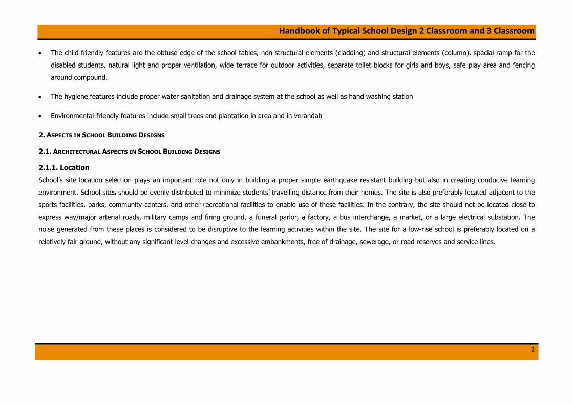
2.2.1.2. Other Supporting Facilities
School’s supporting facilities consist of toilet area, hand-washing station, storage building, sports hall, and parking building. The toilet facility may be located
attached or separated from the classroom block. If attached, it should be located far from the class rooms and must be equipped with sufficient air circulation.
Below are the illustrations of separated toilet facility. Hand-washing facilities may be located attached to the classroom block at the terrace.
Figure 8 Toilet Plan and Toilet Section
Figure 9 Hand-washing Station

Handbook of Typical School Design 2 Classroom and 3 Classroom
9
2.2.2. Drainage System
A proper drainage system is required to maintain the grey water from overflowing to roads and lawns. The site’s drainage
system is usually connected to greater system: city’s drainage and waste water system. To maintain the safety within
school-zone, school’s drainage system must adopt a closed drainage channels system.
As Indonesia is granted by abundant rain water as much as sunlight, it can be maintained to be the alternative natural
resource for water supply. The excessive rain water must be managed well to prevent flood and water overflow. Below is
the schematic of rain water handling system. The main concept of the rain water handling system is to flow the water as
soon as can be, both to be absorbed by the soils directly and to be flowed to the drainage system.
In other hand, the rain water can also be harvested and reused as an alternative water resource. If managed well, the harvested rain water can be stored, treated,
and used as well as the clean water supply for daily use. The rain water that is kept can be used for flushing the toilets, watering the plants, and even for washing.
Below is the illustration of rain water harvesting concept.
Figure 11 Rain Water Handling Concept (left), Rain Water Harvesting Concept Illustration (middle), Schematic: Site’s Drainage system (right)
Figure 10 Closed Drainage System

Handbook of Typical School Design 2 Classroom and 3 Classroom
10
2.2.3. Road and Accessibility
The access to school should be carefully considered and must avoid busy traffic nodes. Bus turning circles and pick-up points require careful attention particularly in
relation to safety aspects. Also, there should be a separation between vehicular and pedestrian access roads in school area. An adequate parking area is also
necessary within the school area, both for cars and bicycles.
To preserve the soil’s water-absorbing ability, the road may be covered by grass blocks, gravels, of paving blocks instead of asphalt and concrete blocks. This also
means to reduce the heat-radiation caused by the sunlight exposure to the asphalt/concrete blocks. As a mean of disaster mitigation, each class in the building must
be equipped with an emergency exit headed right away to open space. In a multi-storey school, emergency stairs also must be provided.
Figure 12 School's Accessibility (left), Non-Asphalt/Concrete Material Selection for Road Cover (middle and right)

Handbook of Typical School Design 2 Classroom and 3 Classroom
11
2.2.4. Thermal Comfort
As it lies on the world’s equatorial zone, Indonesia granted by abundant sunlight, heavy rainfall, and high level of humidity. Along with the climate state, Indonesian
has a different level of thermal comfort compared to those in other 4-seasons-countries: approx. 23–25°C. Therefore, such treatments are needed to reach the
thermal comfort level, especially inside a building.
2.2.4.1. Air Flow
The basic principle of natural air handling is the nature of hot air and cool air themselves. The pressure difference between the hot and cool air caused them to
switch place. As the hot air is lighter than the cool air, it is always pushed to the higher areas. Thus, both sides of wall must have openings on its bottom and
top areas to preserve natural air flow within the room. This air pressure difference caused the air to flow inside the building and generate wind that may reduce
the humidity inside the building. Below is a schematic illustration of natural air flow handling within a room in the building.
Figure 13 Schematic: Air Flow Within Building

Handbook of Typical School Design 2 Classroom and 3 Classroom
12
2.2.4.2. Natural Lighting
Wall openings are made not only to maintain the quality of air flow but also to provide natural lighting into the room. The building blocks are preferably facing
north-south to minimize penetration of direct sunlight into the room. With this arrangement, the room may receive adequate natural lighting from the daylight,
but not the heat. If the buildings are facing east-west, some shading devices are needed to reduce the glare caused by direct sunlight.
Figure 14 Wall Openings in Classroom Block (left) and Various Sun-Shading Devices (Pergolas, Blinds, Shutters) (source:
http://www.gawler.sa.gov.au/webdata/resources/images/Shading.jpg) (right)
2.2.5. Lightings
Bright light coming through the windows and door opening was sometimes reflected from the white/blackboard and students sitting at the end of the front two rows
in the classroom experienced reflected glare from the board. The solutions consist of inclining the boards with a 5-degree tilt and making the windows opaque for
the distance of 1.8 m from the board. All teaching rooms may adopt an artificial lighting level of 500 lux and equipped with dimming facilities to facilitate audio-
visual presentation.

Handbook of Typical School Design 2 Classroom and 3 Classroom
13
Figure 15 Classroom Lighting and Electrical Plan (left) and Classroom Interior Illustration (right)
2.2.6. Noise Control
There is currently no international standard for naturally-ventilated classrooms. Background noise level is typically 60 – 65 dBA and reverberation time is typically
1.0 second. The study makes specific recommendations to reduce the reverberation time to 0.5 – 0.8 seconds. This involves the use of acoustic ceiling tiles in
teaching areas, 40% of which would be reflective tiles, and 60% absorptive tiles.
2.2.7. Access for Handicapped
The facilities provided for handicapped usually placed on the ground to the first floor to make it more accessible for the users. If it is located on the higher storey,
ramps and/or elevators are required.
Handbook of Typical School Design 2 Classroom and 3 Classroom
14
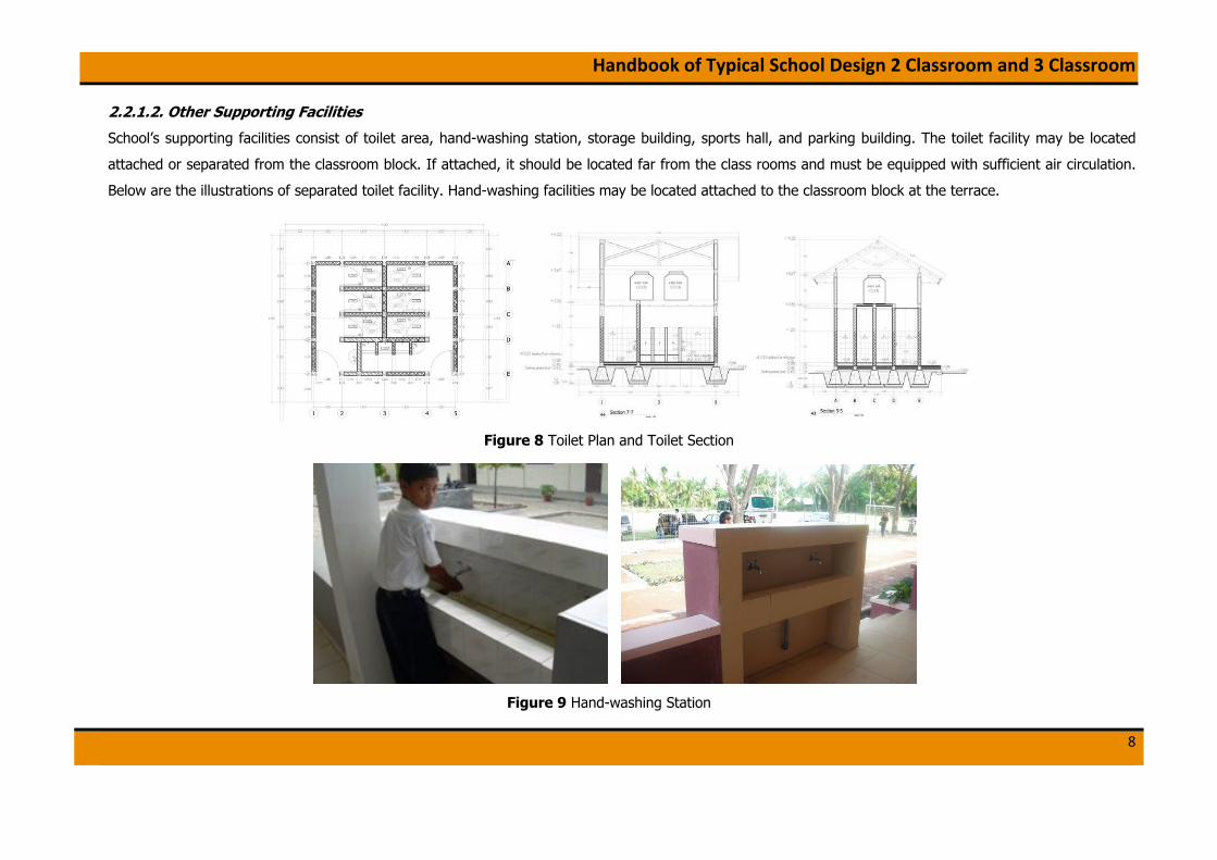
Figure 16 Ramps and Emergency Access From Classroom (left) and Ramps and Emergency Exit Area (right)
2.2.8. Building’s Material
In designing a children friendly school, it is important to note that the building material selections are also play important part. Floor material selections may vary,
but the main important check-list is that the material used for floorings is not slippery. For the classrooms, floor material is preferably also non-glossy material to
prevent the undesired reflections from lightings.
For the mean of students’ safety, it is recommended to use a “non-climbable” material, especially for handrails and ballustrades. The conventional handrail and
balustrade may be changed by aluminum metal sheets or parapets.
To maintain building’s thermal comfort, it is suggested to use clay roofing for the building. Unlike metal sheets, clay is a heat isolator – it absorbs half of the heat
and reflects the other. Thus, the temperature in the building can be reduced. In another hand, it should be noted that clay roofing is heavier than metal sheets. In
earthquake resistant construction, it is suggested that the materials used for roofing system is as light as possible, in order to reduce the earthquake force. For
doors and windows frames, woods are used. Although it has less fire-resistance compared to aluminums, woods is likely more un-rigid material.

Handbook of Typical School Design 2 Classroom and 3 Classroom
15
(wooden frames)
(clay roofing) (low reflection floorings)
(un-climbable balustrade) (anti-slip flooring material)
Figure 17 Some Alternatives for Building Material Selection

Handbook of Typical School Design 2 Classroom and 3 Classroom
16
2.3. STRUCTURAL ASPECTS IN SCHOOL BUILDING DESIGN
2.3.1 Basics of Earthquake Resistant Building
To produce a proper earthquake resistant building, the design and construction of the building should be well conducted. Following are the basic criteria of an
earthquake resistant building:
a) Adequate structural elements, with lateral load resisting system. Columns should be installed for area of wall maximum 10 m2.
b) Proper construction materials, including concrete and mortars mixtures.
c) Good connectivity between structural elements to form integrity between the elements during earthquakes, including beam-foundation, beam-column, column-
foundation, truss element, truss-beam, wall-column, and truss-column connections.
2.3.2 Site/Location
In selecting the location, the designer/building planner should choose low-hazard sites. The location should be safe from natural disasters such as land sliding,
tsunami, flood, and other hazards. The following items give some guidance for site selection:
a) Avoid constructing building on cohesion-less soil with more than 1m of thickness.
b) Avoid constructing building on the slope
c) Avoid constructing building on the edge of a steep slope
d) Avoid constructing building near the coastal line.
e) Choose a flat, firm and dry site.
Handbook of Typical School Design 2 Classroom and 3 Classroom
17
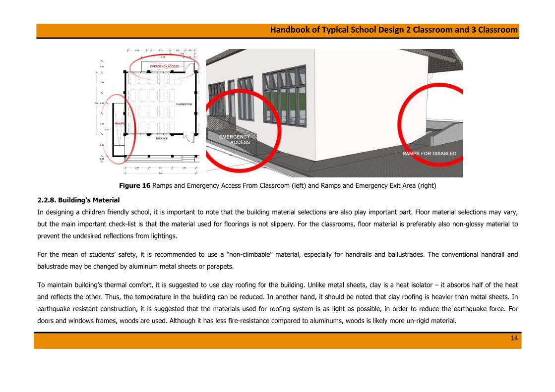
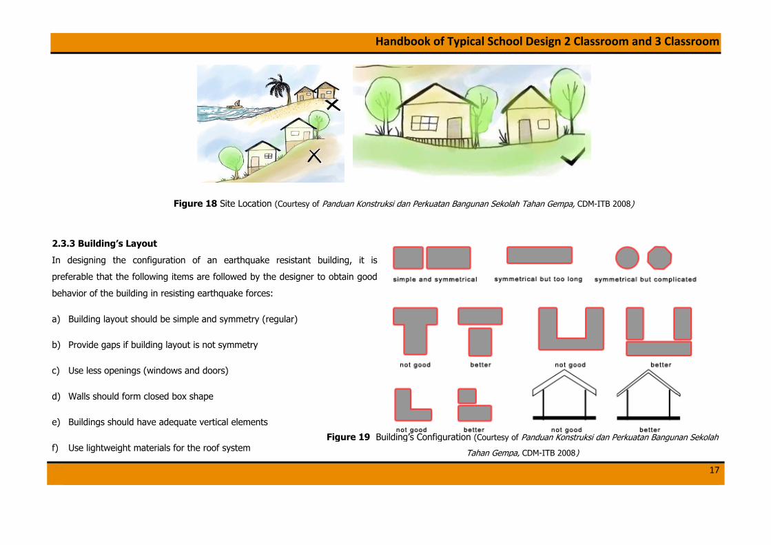
Figure 18 Site Location (Courtesy of Panduan Konstruksi dan Perkuatan Bangunan Sekolah Tahan Gempa, CDM-ITB 2008)
2.3.3 Building’s Layout
In designing the configuration of an earthquake resistant building, it is
preferable that the following items are followed by the designer to obtain good
behavior of the building in resisting earthquake forces:
a) Building layout should be simple and symmetry (regular)
b) Provide gaps if building layout is not symmetry
c) Use less openings (windows and doors)
d) Walls should form closed box shape
e) Buildings should have adequate vertical elements
f) Use lightweight materials for the roof system Figure 19 Building’s Configuration (Courtesy of Panduan Konstruksi dan Perkuatan Bangunan Sekolah
Tahan Gempa, CDM-ITB 2008)

Handbook of Typical School Design 2 Classroom and 3 Classroom
18
2.3.4 Structural Requirements
The basic elements of building are foundation, columns, beams, walls, and roof system. The structure should have adequate structural elements to resist gravity
and lateral loads. It should be noted that all of the structural element must be tied together to provide an integral unit, thus requires proper detailing for
connections.
Figure 20 Structural Requirements (Courtesy of Panduan Konstruksi dan Perkuatan Bangunan Sekolah Tahan Gempa, CDM-ITB 2008)

Handbook of Typical School Design 2 Classroom and 3 Classroom
19
2.3.5 Technical Specification of Materials
There are many materials available in the market for construction, such as sand, split/gravel, cement, bricks, concrete block, reinforcement bar, wood/timber,
rubble stone, lightweight steel profile, etc. Special attention should be placed on the quality of all materials. Good quality of buildings needs good quality of
materials.
Based on Indonesia National Standard-Standar Nasional Indonesia (SNI 03-1726-2002), minimum concrete strength of 17,5 MPa (K-215) must be used for buildings.
For reinforcement bar, deformed bar must be used as main bars (longitudinal bars) and stirrups (confinement). For certain case, un-deformed bar may be allowed
to be used for confinement.
2.3.6 Analysis and Design of the Structure
The analysis of the structure was conducted by modeling the structure as a confined masonry structure. For confined masonry structures, the contribution of the
walls to the overall stiffness of the structures is taken into consideration. Therefore, the walls, columns, beams, and roof trusses were the structural elements. The
load applied to the structure is based on the loading criteria stated on: Peraturan Perencanaan dan Pembebanan untuk Rumah dan Gedung- 1983 (Indonesia
Loading Standard), SNI 03-2847-2002 for design of the concrete element and loading combination, and SNI 03-1726-2002 for the earthquake load. The target
performance level was to have minimum damage due to design earthquake, thus elastic analysis was carried out.
2.3.7 Design Notes
• In adopting this design, the school community should determine on how many rooms needed for the school. The design must be adopted as an integral unit
(block) of 2 classrooms or 3 classrooms.
• This school is designed to meet the minimum criteria provided in Standar Sarana dan Prasarana Sekolah/Madrasah Pendidikan Umum (Standard of Facilities in
Public Education School/Madrasah).

Handbook of Typical School Design 2 Classroom and 3 Classroom
20
3. TYPICAL DESIGN OF 2 ROOMS SCHOOL BUILDING
3.1 Architectural Drawings
8.00 8.00
2.67 2.67 2.67 2.67 2.67 2.67
1.405.101.501.406.48
1.40
25.40
6.00
2.50
2.36
2.34
2.31
7.00
11.3
8
0.60
2.15 2.15 1.08
2.78
1.70 4.80 1.20
1.28
TERRACE
CLASSROOM CLASSROOM
VPSCALE
PLANAR
0.52
2.00
0.13
Note:
All dimensions are in meters unless noted otherwise
Elevations are in maters unless noted otherwise
All dimensions presented must be followed
Drawing no. AR-1 Plan

Handbook of Typical School Design 2 Classroom and 3 Classroom
21
VPSCALE
VIEWAR
VPSCALE
VIEWAR
Note:
All dimensions are in meters unless noted otherwise
Elevations are in maters unless noted otherwise
All dimensions presented must be followed
Drawing no. AR- 2 View

Handbook of Typical School Design 2 Classroom and 3 Classroom
22
± 0.00
+ 1.10
+ 2.35
+ 3.00+ 3.50
+ 4.10
+ 6.35
- 0.62
CLASSROOM
8.00 8.002.67 2.67 2.67 2.67 2.67 2.67
16.00
CLASSROOM
CLAY ROOFINGS
WOODEN JALOUSIE
WOODEN JALOUSIE
WOODEN DOORFRAMESGLASS WINDOW
WOODEN DOOR PANEL
ANTI-SLIP FLOORING
CONCRETE ROOSTER
6/12 timberbracing
Drawing no. AR-3 Long Section
Note:
All dimensions are in meters unless noted otherwise
Elevations are in maters unless noted otherwise
All dimensions presented must be followed

Handbook of Typical School Design 2 Classroom and 3 Classroom
23
WOODENJALOUSIE
VPSCALE
SECTIONAR
1.00 0.60 2.50 7.00 1.20 0.9013.20
± 0.00
+ 1.10
+ 2.35
+ 3.00+ 3.50
+ 4.10
+ 6.35
- 0.62
TERRACE CLASSROOM EMERGENCYEXIT
WOODENJALOUSIE
METALHANDRAIL
PLANTER BOX
LOOSE PEBBLES
CLOSEDDRAINAGE SYSTEM
30°
VPSCALE
SECTIONAR
1.000.60 2.50 7.00 1.20 0.9013.20
± 0.00
+ 1.10
+ 2.35
+ 3.00+ 3.50
+ 4.10
+ 6.35
- 0.62
TERRACE CLASSROOM EMERGENCYEXIT
CLAY ROOFINGS
WOODENJALOUSIE
WOODENWINDOW PANEL
METALHANDRAIL
PLANTER BOX
LOOSE PEBBLES
CLOSEDDRAINAGE SYSTEM
30°
Note:
All dimensions are in meters unless noted otherwise
Elevations are in maters unless noted otherwise
All dimensions presented must be followed
Drawing no. AR-4 Cross Section View
Handbook of Typical School Design 2 Classroom and 3 Classroom
24
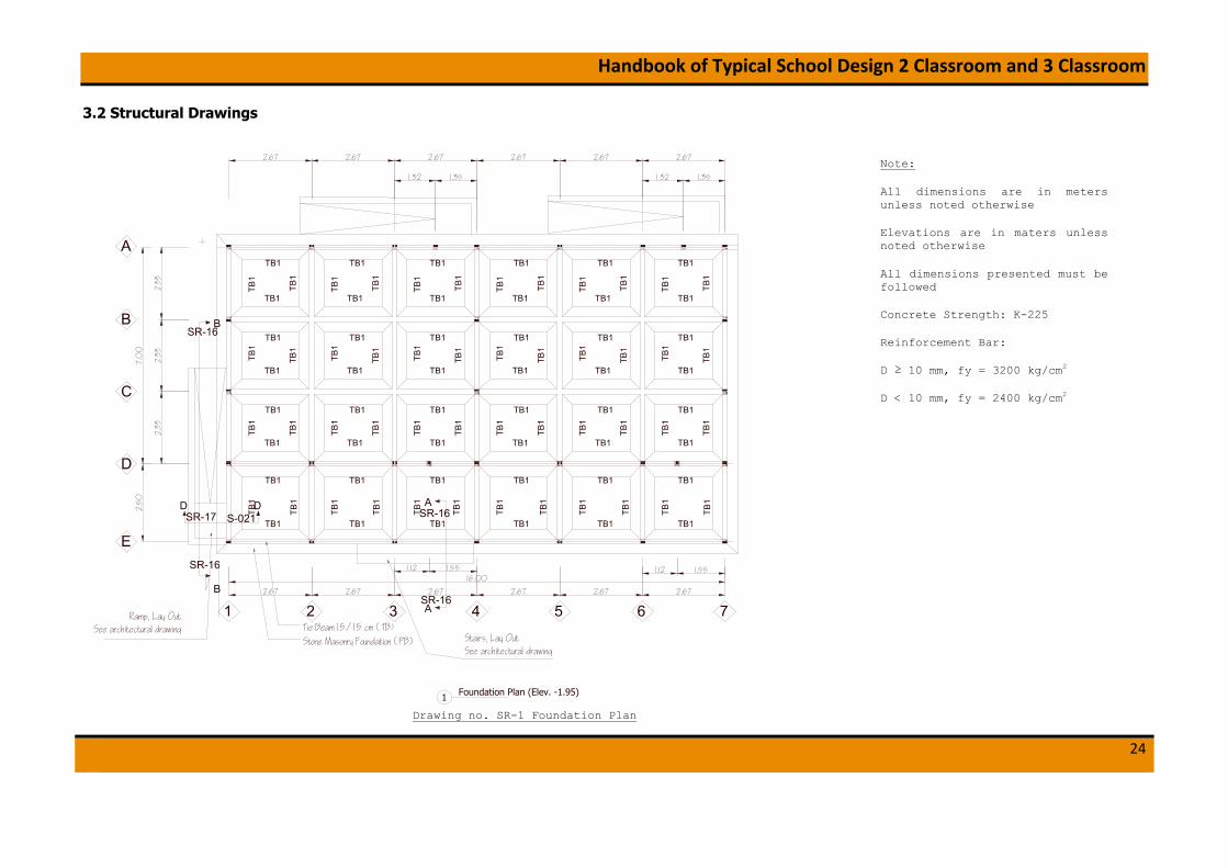
3.2 Structural Drawings
TB1
TB1
TB1
TB1
TB1
TB1
TB1
TB1
TB1
TB1
TB1
TB1
TB1
TB1
1.12 1.55
1.351.32
1.12 1.55
1.351.32
2.33
TB1
TB1
TB1
TB1
TB1
TB1
TB1
TB1
TB1
TB1
TB1
TB1
TB1
TB1
TB1
TB1
TB1
TB1
TB1
TB1
TB1
TB1
TB1
TB1
TB1
TB1
TB1
TB1
2.67 2.67 2.67 2.67
2.67 2.67 2.67 2.67 2.67 2.67
2.5
0
2.33
2.33
1 2 3 4 5 6 7Tie Beam 15/15 cm (TB)
Stone Masonry Foundation (PB)
Ramp, Lay OutSee architectural drawing
Stairs, Lay OutSee architectural drawing
TB1
TB1
TB1
TB1
TB1
TB1
TB1 TB1
TB1 TB1
B
B
SR-16
SR-16
A
ASR-16
SR-16DD
SR-17 S-021 TB1
TB1
TB1
TB1
TB1
TB1
TB1
TB1
TB1
TB1
TB1
TB1
TB1
TB1
TB1
TB1
TB1
TB1
TB1
TB1
TB1 TB1TB1 TB1TB1TB1
7.0
0
TB1
TB1
TB1
TB1
TB1
TB1
TB1
TB1
TB1
TB1
TB1
TB1
TB1
TB1
TB1
TB1
TB1
TB1
2.672.67
C
B
A
D
E
16.00
Foundation Plan (Elev. -1.95)1
Note:
All dimensions are in meters unless noted otherwise
Elevations are in maters unless noted otherwise
All dimensions presented must be followed
Concrete Strength: K-225
Reinforcement Bar:
D ≥ 10 mm, fy = 3200 kg/cm2
D < 10 mm, fy = 2400 kg/cm2
Drawing no. SR-1 Foundation Plan

Handbook of Typical School Design 2 Classroom and 3 Classroom
25
1.12 1.55
1.351.32
1.12 1.55
1.351.32
K1 K1
K1 K1
2.67 2.67 2.67 2.67
2.67 2.67 2.67 2.67 2.67 2.672.
50
2.33
2.33
1 2 3 4 5 6 7
2.33
7.0
0
2.672.67
C
B
A
D
E
16.00
K1
K1
K1
K1
K1
K1
K1
K1
K1
K1
K1
K1
K1
K1
K1
K1
K1
K1
K1
K1
K1
K1
K1
K1
K1
K1
K1
Practical Column Plan (Elev. ±0.00)2
Note:
All dimensions are in meters unless noted otherwise
Elevations are in maters unless noted otherwise
All dimensions presented must be followed
Concrete Strength: K-225
Reinforcement Bar:
D ≥ 10 mm, fy = 3200 kg/cm2
D < 10 mm, fy = 2400 kg/cm2
Drawing no. SR-2 Practical Column Plan

Handbook of Typical School Design 2 Classroom and 3 Classroom
26
2.67 2.67 2.67 2.67
2.67 2.67 2.67 2.67 2.67 2.672.
50
2.33
2.33
1 2 3 4 5 6 7
2.33
7.0
0
2.672.67
C
B
A
D
E
16.00
K1
K1
K1
K1
K1
K1
K1
K1
K1
K1
K1
K1
K1
K1
K1
K1
K1
K1
K1
K1
K1
K1
K1
K1
K1
K1
K1
RB RB RB RB RB RB RB
RBRBRBRBRBRB
BLBLBLBLBLBL
BL
BL
BL
BL
BL
BL
BL
BL
BL
BLBLBLBLBLBL
Lintel Beam & Ring Beam Plan (Elev. +2.55)3
Note:
All dimensions are in meters unless noted otherwise
Elevations are in maters unless noted otherwise
All dimensions presented must be followed
Concrete Strength: K-225
Reinforcement Bar:
D ≥ 10 mm, fy = 3200 kg/cm2
D < 10 mm, fy = 2400 kg/cm2
Drawing no. SR-3 Lintel Beam and Ring Beam Pl

Handbook of Typical School Design 2 Classroom and 3 Classroom
27
2.67 2.67 2.67 2.67
2.67 2.67 2.67 2.67 2.67 2.67
2.33
2.33
1 2 3 4 5 6 7
2.33
7.0
0
2.672.67
C
B
A
D16.00
K1
K1
K1
K1
K1
K1
K1
K1
K1
K1
K1
K1
K1
K1
K1
K1
K1
K1
K1
K1
RBRBRBRBRBRB
RB
RB
RB
RB
RB
RB
RB
RB
RB
RBRBRBRBRBRB
Ring Beam Plan (Elev. +3.71)4
Note:
All dimensions are in meters unless noted otherwise
Elevations are in maters unless noted otherwise
All dimensions presented must be followed
Concrete Strength: K-225
Reinforcement Bar:
D ≥ 10 mm, fy = 3200 kg/cm2
D < 10 mm, fy = 2400 kg/cm2
Drawing no. SR-4 Ring Beam Plan

Handbook of Typical School Design 2 Classroom and 3 Classroom
28
Ø 10
− 2
00
Ø 10 − 200
Y
Y
X X
Ø 10 − 200 Ø 10 − 200 Ø 10 − 200
Ø 10 − 200 Ø 10 − 200 Ø 10 − 200 Ø 10 − 200
Ø 10
− 2
00
Ø 10
− 2
00
Ø 10
− 2
00
2.67 2.67 2.67 2.67
2.67 2.67 2.67 2.67 2.67 2.672.
50
2.33
2.33
1 2 3 4 5 6 7
2.33
7.0
0
2.672.67
C
B
A
D
E16.00
Ø 10 − 200 Ø 10 − 200 Ø 10 − 200 Ø 10 − 200
Ø 10 − 200 Ø 10 − 200 Ø 10 − 200 Ø 10 − 200
Ø 10
− 2
00
Ø 10
− 2
00
Ø 10
− 2
00
Ø 10
− 2
00
Ø 10
− 2
00
Ø 10
− 2
00
Ø 10
− 2
00
Ø 10
− 2
00
Slab Reinforcement (Elev. ± 0.00)5
Note:
All dimensions are in meters unless noted otherwise
Elevations are in maters unless noted otherwise
All dimensions presented must be followed
Concrete Strength: K-225
Reinforcement Bar:
D ≥ 10 mm, fy = 3200 kg/cm2
D < 10 mm, fy = 2400 kg/cm2
Drawing no. SR-5 Slab Reinforcement
Handbook of Typical School Design 2 Classroom and 3 Classroom
29
1 2 3 4 5 6
E
C
B
A
1 2 3 4 5 6
E
C
B
A
2.67 2.67 2.67 2.67
2.67 2.67 2.67 2.67 2.67 2.672.
50
2.33
2.33
1 2 3 4 5 6 7
2.33
7.0
0
2.672.67
C
B
A
D
E16.00
DD
7
7
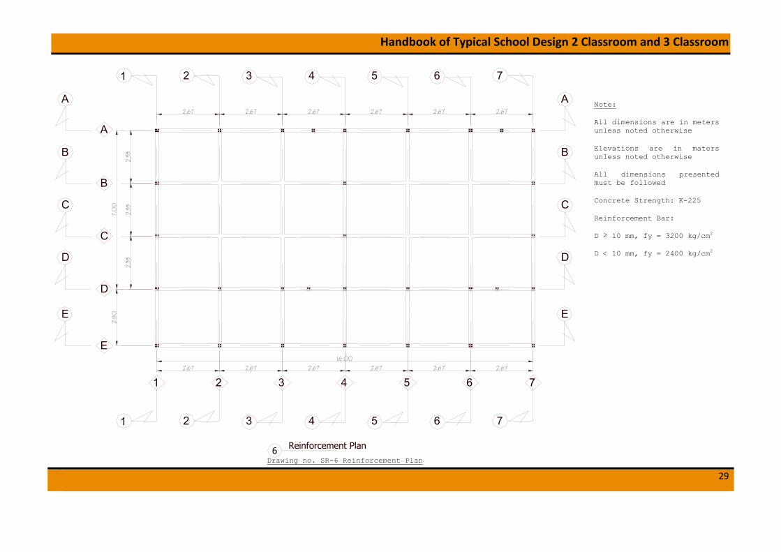
Reinforcement Plan 6
Note:
All dimensions are in meters unless noted otherwise
Elevations are in maters unless noted otherwise
All dimensions presented must be followed
Concrete Strength: K-225
Reinforcement Bar:
D ≥ 10 mm, fy = 3200 kg/cm2
D < 10 mm, fy = 2400 kg/cm2
Drawing no. SR-6 Reinforcement Plan

Handbook of Typical School Design 2 Classroom and 3 Classroom
30
D 13 - 100
D 1
3 -
100
1.00
0.15
1.00
0.15
1.00
0.3
00
.10
D 13 − 100D 13 − 100
0.0
50
.15
D 13 − 100
Compacted Soil
0.15
Ø 10 − 200
0.5
5
±0.00
-0.55 GROUND LEVEL
0.2
0
Z Z
Local Footings (needed to meet deep hard soil level)8
Foot Plate Foundation Plan7
0.80
0.5
5
0.15
0.0
5
AanstampingCompacting Sand
Stone Masonry Foundation
Compacting Soil Filling
±0.00
Anchor 10 - 1000
Tie Beam 15/15 cmConcrete Floor Slab of Thickness 12 cmStone Gravel 10 cmCompacted Sand 5 cm
Ø 10 − 200
-0.55 GROUND LEVEL
Stone Masonry Foundation - Detail (PB)9
Hard Soil
100 Year flood level
minimum 80 cm
AanstampingCompacting SandHard Soil
Concrete Floor Slab of Thickness 12 cmStone Gravel 10 cmCompacted Sand 5 cm
conc
rete
cov
er m
in 7
cm
Note:
All dimensions are in meters unless noted otherwise
Elevations are in maters unless noted otherwise
All dimensions presented must be followed
Concrete Strength: K-225
Reinforcement Bar:
D ≥ 10 mm, fy = 3200 kg/cm2
D < 10 mm, fy = 2400 kg/cm2
Drawing no. SR-7 Foundation

Handbook of Typical School Design 2 Classroom and 3 Classroom
31
A
2 Ø8 - 1000
2 Ø8 2 Ø8 2 Ø8
1,00
minimum 80 cm
> 65
.d
> 12.d
> 6.d
> 5.d
45°
90° 0.2
2 Ø8 - 1000
1,00 1,00 1,00 1,00 1,00 1,00 1,00 1,00
45°
45°
Min. 40 cm
Min
. 40c
m
min 6 c
m
Min
. 40c
m
45°
HARD SOIL
100 YEAR FLOOD LEVEL
Min
. 40c
m
min 6 cm
Min. 40 cmmin 6 cm
C
B
TB1'
TB1'
TB1
TB1
K1' K1'
K1 K1
RB'
RB'
RB
RB
BL'
BL'
BL
BL
K1' K1'
K1 K1
RB'
RB'
RB
RB
TB1'
TB1'
TB1
TB1
2,50 2,33E D C A
0,15
4,10
+2.55
±0.00
0,15+4.10
1,40
GROUND LEVEL−0.550,55
2,55
Reinforcement Grid 1,4 & 712
Detail Foundation Anchor D10-1000 mm11
Detail Wall Anchor Ø8-1000 mm10
Detail C15Detail B14Detail A13
K1'K1'
K1K1
2 Ø8 - 1000
K1' K1'
K1 K1
K1' K1'
K1 K1
TB1'
TB1'
TB1
TB1
RB'
RB'
RB
RB
BL'
BL'
BL
BL
TB1'
TB1'
TB1
TB1
RB'
RB'
RB
RB
BL'
BL'
BL
BL
2,33B
2,33
Note:
All dimensions are in meters unless noted otherwise
Elevations are in maters unless noted otherwise
All dimensions presented must be followed
Concrete Strength: K-225
Reinforcement Bar:
D ≥ 10 mm, fy = 3200 kg/cm2
D < 10 mm, fy = 2400 kg/cm2
Drawing no.SR-8 Reinforcement grid 1, 4 & 7

Handbook of Typical School Design 2 Classroom and 3 Classroom
32
> 65
.d
> 12.d
> 6.d
> 5.d
45°
GROUND LEVEL
HARD SOIL
100 YEAR FLOOD LEVEL
minimum 80 cm1,00 1,00 1,00 1,00
Anchor 10 - 1000
Detail Foundation Anchor D10-1000 mm16
TB1
TB1
K1'
K1 K1
K1' K1'
K1 K1
RB'
RB'
RB
RB
TB1'
TB1'
TB1
TB1
0,15
4,10
+2.55
±0.00
0,15+4.10
1,40
−0.550,55
2,55K1'K1'
K1K1
TB1'
TB1'
K1'
Reinforcement Grid 2,3,5 & 617
2,50 7,00E D A
Note:
All dimensions are in meters unless noted otherwise
Elevations are in maters unless noted otherwise
All dimensions presented must be followed
Concrete Strength: K-225
Reinforcement Bar:
D ≥ 10 mm, fy = 3200 kg/cm2
D < 10 mm, fy = 2400 kg/cm2
Drawing no. SR-9 Reinforcement grid 2,3,5 &

Handbook of Typical School Design 2 Classroom and 3 Classroom
33
minimum 80 cm
2 Ø8 2 Ø8
1,00
765
2 Ø8
BL'
BL'
BL
BL
TB1'
TB1'TB1
TB1
2 Ø8
K1'K1'
K1K1
> 65
.d
> 12.d
> 6.d
> 5.d
45°
GROUND LEVEL
HARD SOIL
100 YEAR FLOOD LEVEL
90° 0.2
1,00 1,00 1,00 1,00 1,00 1,00
Detail Foundation Anchor D10-1000 mm19Detail Wall Anchor Ø8-1000 mm18
K1 K1
2,674
0,15
4,10
+2.55
±0.00
0,15+4.10
1,40
0,55
2,55K1'K1'
K1K1
K1' K1'
K1 K1
RB'
RB'
RB
RB
2,67 2,67
K1' K1'
K1 K1
K1' K1'
RB'
RB'
RB
RB
BL'
BL'
BL
BL
TB1'
TB1'TB1
TB1
RB'
RB'
RB
RB
BL'
BL'
BL
BL
TB1'
TB1'TB1
TB1
RB'
RB'
BL'
BL'
−0.55
Reinforcement Grid A & D (Continue)20
Note:
All dimensions are in meters unless noted otherwise
Elevations are in maters unless noted otherwise
All dimensions presented must be followed
Concrete Strength: K-225
Reinforcement Bar:
D ≥ 10 mm, fy = 3200 kg/cm2
D < 10 mm, fy = 2400
Drawing no. SR-10 Reinforcement grid A & D (Continue)

Handbook of Typical School Design 2 Classroom and 3 Classroom
34
2 Ø8 2 Ø8
1,00
BL'
BL'
BL
BL
TB1'
TB1'TB1
TB1
2 Ø8
K1'K1'
K1K1
> 6
5.d
> 12.d
> 6.d
> 5.d
45°
GROUND LEVEL
100 YEAR FLOOD LEVEL
HARD SOIL
minimum 80 cm
90° 0.2
1,00 1,00 1,00 1,00 1,00 1,00
Detail Foundation Anchor D10-1000 mm22Detail Wall Anchor Ø8-1000 mm21
2,67431
0,15
4,10
+2.55
±0.00
0,15+4.10
1,40
0,55
2,55
2,672
2,67
−0.55
K1 K1
K1' K1'
K1 K1
K1' K1'
K1 K1
K1' K1'
K1 K1
K1' K1'2 Ø8
RB'
RB'
RB
RB
BL'
BL'
BL
BL
TB1'
TB1'TB1
TB1
RB'
RB'
RB
RB
BL'
BL'
BL
BL
TB1'
TB1'TB1
TB1
RB'
RB'
RB
RB
Reinforcement Grid A & D23
Note:
All dimensions are in meters unless noted otherwise
Elevations are in maters unless noted otherwise
All dimensions presented must be followed
Concrete Strength: K-225
Reinforcement Bar:
D ≥ 10 mm, fy = 3200 kg/cm2
D < 10 mm, fy = 2400 kg/cm2
Drawing no. SR-11 Reinforcement grid A & D

Handbook of Typical School Design 2 Classroom and 3 Classroom
35
0,55minimum 80 cm
765
> 65
.d
> 12.d
> 6.d
> 5.d
45°
GROUND LEVEL
HARD SOIL
100 YEAR FLOOD LEVEL
TB1'
TB1'TB1
TB1−0.55
TB1
TB1
1,00 1,00
Anchor 10 - 1000
Detail Foundation Anchor D10-1000 mm24
K1 K1
2,674
0,15
±0.00
0,15+4.10
3,95
K1'K1'
K1K1
2,67 2,67
K1' K1'
Reinforcement Grid B & C (Continue)25
Note:
All dimensions are in meters unless noted otherwise
Elevations are in maters unless noted otherwise
All dimensions presented must be followed
Concrete Strength: K-225
Reinforcement Bar:
D ≥ 10 mm, fy = 3200 kg/cm2
D < 10 mm, fy = 2400 kg/cm2
Drawing no. SR-12 Reinforcement grid B & C

Handbook of Typical School Design 2 Classroom and 3 Classroom
36
> 65
.d
> 12.d
> 6.d
> 5.d
45°
GROUND LEVEL
100 YEAR FLOOD LEVEL
GROUND LEVEL
HARD SOIL
100 YEAR FLOOD LEVEL
minimum 80 cm
0,15
±0.00
0,15+4.10
0,55
3,95
−0.55
K1 K1
K1' K1'
K1 K1
K1' K1'
TB1'
TB1'TB1
TB1 TB1'
TB1'TB1
TB1
1,00 1,00
Anchor 10 - 1000
Detail Foundation Anchor D10-1000 mm26
Reinforcement Grid B & C27
2,67431
2,672
2,67
Note:
All dimensions are in meters unless noted otherwise
Elevations are in maters unless noted otherwise
All dimensions presented must be followed
Concrete Strength: K-225
Reinforcement Bar:
D ≥ 10 mm, fy = 3200 kg/cm2
D < 10 mm, fy = 2400 kg/cm2
Drawing no. SR-13 Reinforcement grid B & C
Handbook of Typical School Design 2 Classroom and 3 Classroom
37
minimum 80 cm0,55
4
> 6
5.d
> 12.d
> 6.d
> 5.d
45°
GROUND LEVEL
HARD SOIL
100 YEAR FLOOD LEVEL
K1 K1
2,677
0,15
+2.55
±0.00
0,15
2,55K1'K1'
K1K1
K1' K1'
K1 K1
RB'
RB'
RB
RB
2,67 2,67
K1' K1'
K1 K1
K1' K1'
65
TB1'
TB1'TB1
TB1
RB'
RB'
RB
RB
TB1'
TB1'TB1
TB1
RB'
RB'
RB
RB
TB1'
TB1'TB1
TB1−0.55
1,00 1,001,00 1,001,00 1,00
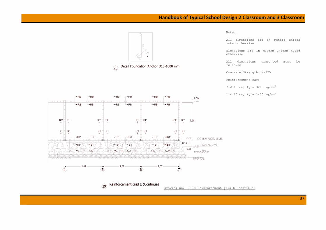
Detail Foundation Anchor D10-1000 mm28
Reinforcement Grid E (Continue)29
Note:
All dimensions are in meters unless noted otherwise
Elevations are in maters unless noted otherwise
All dimensions presented must be followed
Concrete Strength: K-225
Reinforcement Bar:
D ≥ 10 mm, fy = 3200 kg/cm2
D < 10 mm, fy = 2400 kg/cm2
Drawing no. SR-14 Reinforcement grid E (continue)

Handbook of Typical School Design 2 Classroom and 3 Classroom
38
> 6
5.d
> 12.d
> 6.d
> 5.d
45°
Detail Foundation Anchor D10-1000 mm30
1,00 1,001,00 1,001,00 1,00
GROUND LEVEL
100 YEAR FLOOD LEVEL
HARD SOIL
minimum 80 cm
2,67431
0,15
+2.55
±0.00
0,15
0,55
2,55
2,672
2,67
−0.55
K1 K1
K1' K1'
K1 K1
K1' K1'
K1 K1
K1' K1'
K1 K1
K1' K1'
RB'
RB'
RB
RB
TB1'
TB1'TB1
TB1
RB'
RB'
RB
RB
TB1'
TB1'TB1
TB1
RB'
RB'
RB
RB
TB1'
TB1'TB1
TB1
Reinforcement Grid E31
Note:
All dimensions are in meters unless noted otherwise
Elevations are in maters unless noted otherwise
All dimensions presented must be followed
Concrete Strength: K-225
Reinforcement Bar:
D ≥ 10 mm, fy = 3200 kg/cm2
D < 10 mm, fy = 2400 kg/cm2
Drawing no. SR-15 Reinforcement grid E

Handbook of Typical School Design 2 Classroom and 3 Classroom
39
0,800,800,80Hard Soil
Ø 10 − 200 Ø 10 − 200
minimum 80 c
Concrete Floor Slab of Thickness 12 cmStone Gravel 10 cmCompacted Sand 5 cm
Concrete Floor Slab of Thickness 12 cmStone Gravel 10 cmCompacted Sand 5 cm
Concrete Floor Slab of Thickness 12 cmStone Gravel 10 cmCompacted Sand 5 cm
Hard Soil Hard Soil Hard Soil
Stone Masonry Foundation
2,67
Sloof 15/15 cm Sloof 15/15 cm
Stone Masonry Foundation
Sloof 15/15 cm
Stone Masonry Foundation
0,80
42,67 2,67
1 2 3
Sloof 15/15 cm
Stone Masonry FoundationGROUND LEVEL
Ø 10 − 200
100 YEAR FLOOD LEVEL
54
Ø 10 − 200 Ø 10 − 200Concrete Floor Slab of Thickness 12 cm
Stone Gravel 10 cmCompacted Sand 5 cm
Concrete Floor Slab of Thickness 12 cmStone Gravel 10 cm
Compacted Sand 5 cm
Hard Soil Hard Soil Hard Soil Hard Soil
GROUND LEVEL
Floor Reinforcement Section X-X (Elev. -0.03)32
2,672,67
Ø 10 − 200
0,800,802,67
0,800,80
76
Sloof 15/15 cm
Stone Masonry Foundation
Sloof 15/15 cm
Stone Masonry Foundation
Sloof 15/15 cm
Stone Masonry Foundation
Sloof 15/15 cm
Stone Masonry Foundation
Concrete Floor Slab of Thickness 12 cmStone Gravel 10 cm
Compacted Sand 5 cm
Hard Soil
Hard SoilHard Soil
GROUND LEVELGROUND LEVEL
Stone Masonry FoundationAanstamping
Compacted Sand
Compacted Soil Filling Stone Masonry FoundationAanstamping
Compacted Sand
Compacted Soil Filling
Stone Masonry FoundationAanstamping
Compacted Sand
0,30 0,30
0,050,15
0,37
0,20
0,25
0,15
0,15
-0.75
-0.55
Ø 10 − 200
1 x Ø 8
1 x Ø 8
0,50
0,50
0,50
Ø 10 − 200
0,20
0,05
0,15
0,50
0,12
-0.55
0,20
Ramp Detail (Section B-B from SR-1)34Stairs Detail (Section A-A from SR-1)33
Note:
All dimensions are in meters unless noted otherwise
Elevations are in maters unless noted otherwise
All dimensions presented must be followed
Concrete Strength: K-225
Reinforcement Bar:
D ≥ 10 mm, fy = 3200 kg/cm2
D < 10 mm, fy = 2400 kg/cm2
Drawing no.SR-16 Floor Reinforcement Sec X-X

Handbook of Typical School Design 2 Classroom and 3 Classroom
40
Stone Masonry Foundation
0,80
Sloof 15/15 cm
Stone Masonry Foundation
0,80
Sloof 15/15 cm
Stone Masonry Foundation
0,80
D2,33
100 YEAR FLOOD LEVEL
Ø 10 − 200 Ø 10 − 200 Ø 10 − 200
minimum 80 cm
Concrete Floor Slab of Thickness 12 cmStone Gravel 10 cmCompacted Sand 5 cm
Concrete Floor Slab of Thickness 12 cmStone Gravel 10 cmCompacted Sand 5 cm
Concrete Floor Slab of Thickness 12 cmStone Gravel 10 cmCompacted Sand 5 cm
Hard SoilHard SoilHard SoilHard SoilHard Soil
GROUND LEVEL GROUND LEVEL
Floor Reinforcement Section Y-Y ( Elev. - 0.03)36
Sloof 15/15 cm
Stone Masonry Foundation
0,80
Sloof 15/15 cm
Stone Masonry Foundation
0,80
Sloof 15/15 cm
2,50 2,33
E C B A2,33
Hard Soil
Ø 10 − 200
Compacted Soil Filling
0,50
Stone Masonry FoundationAanstamping
Compacted Sand
Stairs Detail (Section D-D from SR-1)37
Note:
All dimensions are in meters unless noted otherwise
Elevations are in maters unless noted otherwise
All dimensions presented must be followed
Concrete Strength: K-225
Reinforcement Bar:
D ≥ 10 mm, fy = 3200 kg/cm2
D < 10 mm, fy = 2400 kg/cm2
Drawing no. SR-17 Floor Reinforcement Sec Y-Y

Handbook of Typical School Design 2 Classroom and 3 Classroom
41
2 D 10 mm
Ø 8 - 100 mm Ø 8 - 150 mm
2 D 10 mm
2 D 10 mm
2 D 10 mm
0.025
0.0
25
0.06
2 D 10 mm
0.15
0.15
0.025
0.0
25
2 D 10 mm
0.025
0.0
25
0.06
NOTATION
B x D
TOP BAR
BOTTOM BARSTRIRRUP
END MID
15 x 15 cm
SECTION
0.15
0.15
0.025
0.0
25
POSITION
RB RB'
WEB BAR
NOTE
0.025
0.0
25
0.06
0.15
0.15
0.025
0.0
25
0.025
0.0
25
0.06
NOTATION
B x D
TOP BAR
BOTTOM BARSTRIRRUP
END MID
2 D 10 mm
Ø 8 - 100 mm
15 x 15 cm
Ø 8 - 150 mm
SECTION
0.15
0.15
0.025
0.0
25
LIST OF TIE BEAM
POSITION
TB1 TB1'
WEB BAR
NOTE
2 D 10 mm
LIST OF RING BEAM
2 D 10 mm
Ø 8 - 100 mm Ø 8 - 150 mm
2 D 10 mm
2 D 10 mm
2 D 10 mm
0.15
0.15
0.025
0.0
25
0.025
0.0
25
0.06
0.15
0.15
0.0250
.025
0.0250
.025
0.06
0.15
0.15
0.025
0.0
25
0.025
0.0
25
0.06
0.15
0.15
0.025
0.0
25
0.025
0.0
25
0.06
NOTATION
B x D
TOP BAR
BOTTOM BARSTRIRRUP
END MID
15 x 15 cm
SECTION
LIST OF LINTEL BEAM
POSITION
BL BL'
WEB BAR
NOTE
NOTATION
B x D
MAIN BARSTRIRRUP
END MID
Ø 8 - 100 mm
15 x 15 cm
Ø 8 - 150 mm
SECTION
LIST OF PRACTICAL COLUMN
POSITION
K1 K1'
4 D 10 mm 4 D 10 mm
NOTE
Reinforcement Detail for Building B&D39
Note:
All dimensions are in meters unless noted otherwise
Elevations are in maters unless noted otherwise
All dimensions presented must be followed
Concrete Strength: K-225
Reinforcement Bar:
D ≥ 10 mm, fy = 3200 kg/cm2
D < 10 mm, fy = 2400 kg/cm2
Drawing no. SR-18 Reinforcement Detail

Handbook of Typical School Design 2 Classroom and 3 Classroom
42
40 D Lap SpliceTop Bar Only
12 L
14 L
40 D Lap SpliceBottom Bar Only
Top Steel Splices Shall Only Be Locatedat Mid Span (L/2)
Bottom Steel Splices Shall Only Be Locatedat Quarter Span (L/4)
20/80 Crank
20/80 Crank
Provide Stirrupsat 75 CTRS OverLength of Splices
Provide Stirrupsat 75 CTRS OverLength of Splices
L
Permissible Beam Splice locations40
Note:
All dimensions are in meters unless noted otherwise
Elevations are in maters unless noted otherwise
All dimensions presented must be followed
Concrete Strength: K-225
Reinforcement Bar:
D ≥ 10 mm, fy = 3200 kg/cm2
D < 10 mm, fy = 2400 kg/cm2
Drawing no. SR-19 Permissible Beam Splice Locations
Handbook of Typical School Design 2 Classroom and 3 Classroom
43
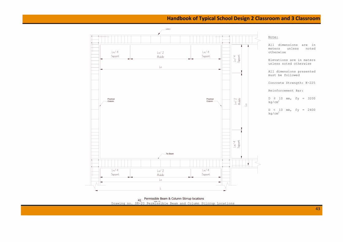
Ln
Ln/4Support
L
Scale: 1:10
Permissible Beam & Column Stirrup locations41
Ln/4Support
Ln/2Middle
Ln
Ln/4Support
Ln/4Support
Ln/2Middle
Ln
Ln/
4Su
ppor
tLn
/4
Supp
ort
Ln/
2M
iddle
Beam
PracticalColumn
Tie Beam
PracticalColumn
Note:
All dimensions are in meters unless noted otherwise
Elevations are in maters unless noted otherwise
All dimensions presented must be followed
Concrete Strength: K-225
Reinforcement Bar:
D ≥ 10 mm, fy = 3200 kg/cm2
D < 10 mm, fy = 2400 kg/cm2
Drawing no. SR-20 Permissible Beam and Column Stirrup Locations

Handbook of Typical School Design 2 Classroom and 3 Classroom
44
Roof Truss Plan49
1.45
7.0
03.
95
1.45 16.00 1.45
0.50
0.50
Note:
All dimensions are in meters unless noted otherwise
Elevations are in maters unless noted otherwise
All dimensions presented must be followed
Drawing no. SR-21 Roof Truss Plan

Handbook of Typical School Design 2 Classroom and 3 Classroom
45
Purlin 6/12 @1500mm
8/12
5/7
18/12
Cleat
8/12
2 x 6/12
8/12
8/12
2
3
4
30°
8/12
7,002,50 1,451,45
Roof Truss Detail - K143
+4.10
+3.68
+6.35
+2.55
ACD
Ring Beam 15/15 cm
Lintel Beam 15/15 cm
Ring Beam 15/15 cm Ring Beam 15/15 cm
Section 144
RIng Beam 15 /15 cm
Steel clams 4.40mmBolt 2 Ø10 mm
Anchor 2 Ø10 mmlength 40cm
8/12
8/12
A
A
B
B
Anchor 2 Ø10 mmlength 40cm
Section A - A45 Section B - B46
Steel clams 4.40mm
Bolt 2 Ø10 mm8/12
8/12
8/12
8/12
RIng Beam15 /15 cm
RIng Beam15 /15 cm
8/12
Purlin 6/12Cleat
8/12Iron sheet 4.40mm /Plank 20.100 mmBolt 3 Ø10 mm
Wooden pin 2 Ø10mm
Section 247
8/12
8/12
8/12
8/12
8/12
Iron sheet 4.40mm /Plank 20.100 mmBolt 3 Ø10 mm
Bolt 4 Ø10 mm
Iron sheet 4.40mm /Plank 20.100 mmBolt 3 Ø10 mm
Wooden pin 2 Ø10mm
Section 348
8/12
2 x 6/12
8/12
8/12Purlin 6/12
Cleat
Bolt 2 Ø10 mm
C
C
Bolt 2 Ø10 mm
8/12
8/12
6/12
Section 449
Section C - C50
Note:
All dimensions are in meters unless noted otherwise
Elevations are in maters unless noted otherwise
All dimensions presented must be followed
Refer to AR-3 for roof truss bracing
Drawing no. SR-22 Roof Truss Detail

Handbook of Typical School Design 2 Classroom and 3 Classroom
46
3.3 Lighting and Water Sanitation
0.15
2.18
2.18
0.15
2.35
0.15
0.50 0.15
0.15
0.055.230.151.121.11
0.15
5.19
0.15
0.15
2.18
0.15
2.18
0.15
2.35
0.150.15 0.350.15
5.332.672.665.34
3.50
3.50
1.080.15
1.22
0.96
16.00
9.50
1.501.50
TLD
1x3
6WTL
D 1
x36W
A
A
TLD
1x3
6WTL
D 1
x36W
B
B
TLD
1x3
6WTL
D 1
x36W
B
B
TLD
1x3
6WTL
D 1
x36W
A
A
TLD
1x3
6WTL
D 1
x36W
E
TLD
1x3
6WTL
D 1
x36W
F
TLD
1x3
6WTL
D 1
x36W
F
TLD
1x3
6WTL
D 1
x36W
E
E F F E
PSL 9 W
G
PSL 9 W
G
PSL 9 W
H
PSL 9 W
H
A,B E,FMDP
From PLN Electrical Pole1-? ,/220V/50Hz/ 3520 kVA
5 Ohm
BC Cable 6 mm²
Electrical Instalation Plan1
0.15
0.15
2.182.18
0.15
Note:
tubelamp 2x40w
socket
T dos
switch
MCB box
KWH meter
PSL 9w
Drawing no. E-1 Electrical Plan

Handbook of Typical School Design 2 Classroom and 3 Classroom
47
0.90
zincallume metal roof
6/126/12
6/126/12
wooden trust 5/12water tank 1m312cm concrete slab4mm plywood
5/10
metal plate
2/30
painted walltile 20/25tile 20/2012cm concrete slab
water tap
paintedwall
paintedwall
paintedwall
tile20/25
tile20/25
tile20/25
±0.00 = 10,596
−0.18 = 10,416
2.50
0.16
1.02
0.60
0.18
−0.28
1.37
+0.13±0.00
+0.13 +0.13
paintedwall
tile20/25
water tank1000lt
4mm plywood
0.90 0.90 1.20 1.00
0.05 0.10
0.53
0.270.16
1.37
1.00
0.20
1.15
0.20
1.41
−0.18±0.00+0.13
−0.98−0.83
+2.60
+3.95
+5.46
0.30
0.60
Scale: 1:50
Section 1-12
4.90
A C E
0.10
0.60
0.10
Ø1"pipe
Ø1"pipe
Ø1"pipeØ 1
2 "pipeØ 1
2 "pipeØ 12 "pipe
Ø 12 "pipe
Ø 12 "pipe
Ø 12 "pipe
Ø 12 "pipe
Ø 12 "pipe
water tank 1000Ltwater tank 1000Lt
Scale: 1:50
Ceiling Piping Plan1
1
1.00
2 3 4 5
1.50 1.50 1.00
0.90
0.90
0.90
1.20
Ø1"pipeØ 12 "pipe
Ø1"pipe
Ø 12 "pipe Ø 1
2 "pipe Ø 12 "pipe Ø 1
2 "pipe
Drawing no. WS-1 Ceiling Piping Plan and Section 1-1

Handbook of Typical School Design 2 Classroom and 3 Classroom
48
painted wall
tile 20/25
painted wall
tile 20/25
painted wall
tile 20/25
painted wall
tile 20/25
±0.00 −0.02+0.13
−0.02+0.13
water tank1000lt
water tank1000lt
0.050.10
0.60
0.150.16
1.37
1.02
0.020.18
1.15
0.20
−0.18±0.00+0.13
−0.98−0.83
+2.60
+3.95
0.34
1.00
0.100.60
0.10
0.05
5.001.001.00
0.60
0.150.15
1.90
1 3 5
Scale: 1:50
Section 2-23
0.95
1.41
+5.70
painted wall
tile 20/25
water tank1000lt
water tank1000lt
0.050.10
0.60
0.150.16
1.37
1.020.02
0.18
1.15
0.20
−0.18±0.00+0.13
−0.98−0.83
+2.60
+3.95
2.50 2.50
0.10 0.60 0.10
0.05
0.15
0.13
0.03
5.001.001.00
1 3 5
Scale: 1:50
Section 3-34
0.850.50
0.30
0.70
painted wall
tile 20/25
7.00
0.95
1.41
+5.707.00
zincallume metal roofwooden trust 5/12water tank 1m312cm concrete slab4mm plywood
painted walltile 20/25tile 20/20squat closet12cm concrete slab
5/10 5/105/10
5/10
5/10 5/10 5/10 5/10
water tapwater tap water tapwater basinwater basin
zincallume metal roofwooden trust 5/12water tank 1m312cm concrete slab4mm plywood
±0.00 = 10,596
−0.28 −0.28
1.00
4mm plywood9mm gypsum board & hollow 40/40/2
painted walltile 20/25tile 20/2012cm concrete slab
−0.18 = 10,416
±0.00 = 10,596
−0.18 = 10,416
±0.00 = 10,596
0.73 0.78 0.78 0.73 1.00
Ø 12 "pipe
Ø1"pipe Ø1"pipe Ø1"pipe Ø1"pipe
Ø 12 "pipe Ø 1
2 "pipe Ø 12 "pipe
Ø 12 "pipe
4mm plywood 4mm plywood
Drawing no. WS-2 Section 2-2 & 3-3

Handbook of Typical School Design 2 Classroom and 3 Classroom
49
1.20
0.90
0.90
0.90
1.00 0.60 0.90 1.490.99
Toilet Plan5
Drawing no. WS-3 Toilet Plan

Handbook of Typical School Design 2 Classroom and 3 Classroom
50
3.4 Bill of Quantities
BOQ Typical 2 Classrooms School Designs
No Items of Works Unit Quantities Unit Rate Total Amount
A Substructure works
A.1 Excavation works:
a Class room and terrace m3 102.36
b Stair m3 1.09
c Ramp m3 8.52
A.2 Compacted fill works:
d Class room and terrace m3 81.56
e Stair m3 0.38
f Ramp m3 10.35
A.3 Sand bed 50 mm consolidated thickness under floor
g Class room and terrace m3 6.58
h Stair m3 0.14
i Ramp m3 1.31
A.4 Compacted gravel t =100 mm under floor for leveling
j Class room and terrace m3 15.99
k Stair m3 0.17
l Ramp m3 2.52
B Foundation Works
B.1 Aanstamping+sand t = 150 mm masonry erection under foundation
a Classroom m3 12.12
b Verandah m3 4.98
c Stair m3 0.67
d Ramp m3 1.01
e Water Station & Parapets m3 2.78
B.2 Stone masonry foundation to:

Handbook of Typical School Design 2 Classroom and 3 Classroom
51
f Classroom m3 55.55
g Verandah m3 22.83
h Stair m3 2.24
i Ramp m3 1.47
j Water Station & Parapets m3 4.05
C Anchorage
a Anchorage between tie beams and foundation Φ10-1000, Classroom kg 147.21
b Anchorage between tie beams and foundation Φ10-1000, Verandah kg 29.98
c Anchorage between tie beams and foundation Φ10-1000, Stair kg 5.33
d Anchorage between tie beams and foundation Φ10-1000, Ramp kg 7.99
e Anchorage between column and brick 2Φ8, classroom kg 67.44
D Vibrated reinforced concrete works K-225
D.1 Column 150/150
a Concrete m3 2.81
b Reinforcement bar kg 429.21
c formwork m2 76.64
D.2 Ring Beam 150/150
d Concrete m3 1.95
e Reinforcement bar kg 264.87
f formwork m2 49.78
D.3 Tie Beam 150/150
g Concrete m3 3.29
h Reinforcement bar kg 661.53
i formwork m2 84.30
D.4 Lintel Beam 150/150
j Concrete m3 1.19
k Reinforcement bar kg 244.50
l formwork m2 30.50
D.5 Concrete floor slab t = 120 mm

Handbook of Typical School Design 2 Classroom and 3 Classroom
52
m Concrete m3 18.24
n Reinforcement bar kg 1,899.50
o formwork m2 5.79
D.6 Concrete stair
p Concrete m3 0.55
q Reinforcement bar kg 24.96
r formwork m2 1.87
D.7 Concrete ramp
s Concrete m3 3.02
t Reinforcement bar kg 308.88
u formwork m2 6.22
D.8 Beam on parapet wall
v Concrete m3 0.36
w Reinforcement bar kg 55.95
x formwork m2 6.45
D.9 Slab concrete t= 120 mm at water station
y Concrete m3 0.22
z Reinforcement bar kg 7.60
aa formwork m2 1.18
E Wall + wall finishing:
E.1 Brickwork in cement and sand (1:4) for construct :
a Class room m2 127.65
b Parapet wall and water station m2 20.41
E.2 Plaster to brick wall, smooth finish with cement coating to :
c Class room m2 255.29
d Parapet wall and water station m2 40.83
E.3 Internal wall painting with apply one coat primer and two coats of approved paint to:
e Class room m2 151.55
E.4 External wall painting with apply one coat primer and two coats of approved paint to:

Handbook of Typical School Design 2 Classroom and 3 Classroom
53
f Class room m2 87.88
g Parapet wall and water station m2 58.69
F Floor finishing
Non slippery Ceramic tiles 300 mm x 300 mm,
a Class room m2 112.00
b Verandah, stair and ramp m2 48.26
c finishing patterns to form ramp surface m2 20.16
G Door frames, window frames and jalousie
a door (5/7) m3 0.10
b window (5/7) m3 0.36
c jalousie (5/7) m3 0.26
d Jalousie grid (1/7) m3 0.12
H Door, windows and concrete rooster
a Front doors, as specified in architectural drawings unit 2.00
b windows glass (650x800 mm), included the frames and hinges if needed, refer to drawings unit 24.00
c window glass (270x710 mm), included the frames and hinges if needed, refer to drawings unit 48.00
d window glass (310x430 mm), included the frames and hinges if needed, refer to drawings unit 8.00
e window glass (200x850 mm), included the frames and hinges if needed, refer to drawings unit 4.00
f concrete rooster unit 20.00
g backdoors, as specified in architectural drawings unit 2.00
I Roofing works and Ceilings
I.1 Roof Trusses
a main chord (8/12) m3 1.32
b stiffener (6/12) m3 0.23
c purlin (6/12) m3 0.50
d Kasau (timber element) (5/7) m3 1.19
e timber bracing (6/12) m3 0.22
f cleat (5/7) m3 0.01
I.2 Roof Cover
Handbook of Typical School Design 2 Classroom and 3 Classroom
54
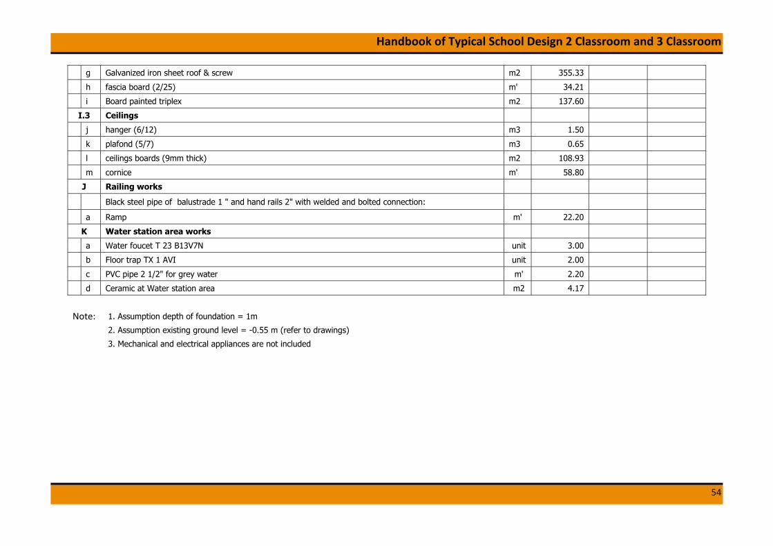
g Galvanized iron sheet roof & screw m2 355.33
h fascia board (2/25) m' 34.21
i Board painted triplex m2 137.60
I.3 Ceilings
j hanger (6/12) m3 1.50
k plafond (5/7) m3 0.65
l ceilings boards (9mm thick) m2 108.93
m cornice m' 58.80
J Railing works
Black steel pipe of balustrade 1 " and hand rails 2" with welded and bolted connection:
a Ramp m' 22.20
K Water station area works
a Water foucet T 23 B13V7N unit 3.00
b Floor trap TX 1 AVI unit 2.00
c PVC pipe 2 1/2" for grey water m' 2.20
d Ceramic at Water station area m2 4.17
Note: 1. Assumption depth of foundation = 1m
2. Assumption existing ground level = -0.55 m (refer to drawings)
3. Mechanical and electrical appliances are not included

Handbook of Typical School Design 2 Classroom and 3 Classroom
55
4. TYPICAL DESIGN OF 3 ROOMS SCHOOL BUILDING
4.1 Architectural Drawings
5.101.501.406.48
1.40
6.00
2.50
2.36
2.34
2.31
7.00
11.3
8
0.60
2.15 2.151.08
2.781.70
4.80 1.20
1.28
TERRACE
CLASSROOM CLASSROOM CLASSROOM
8.00 8.00 8.00
2.67 2.67 2.67 2.67 2.67 2.67 2.67 2.67 2.67
1.405.101.501.40
2.00 4.80 1.432.00
0.13
Drawing no. AR-1 Plan
Note:
All dimensions are in meters unless noted otherwise
Elevations are in meters unless noted otherwise
All dimensions presented must be followed

Handbook of Typical School Design 2 Classroom and 3 Classroom
56
VPSCALE
VIEWAR
VPSCALE
VIEWAR Drawing no. AR-2 View
Note:
All dimensions are in meters unless noted otherwise
Elevations are in maters unless noted otherwise
All dimensions presented must be followed
Handbook of Typical School Design 2 Classroom and 3 Classroom
57
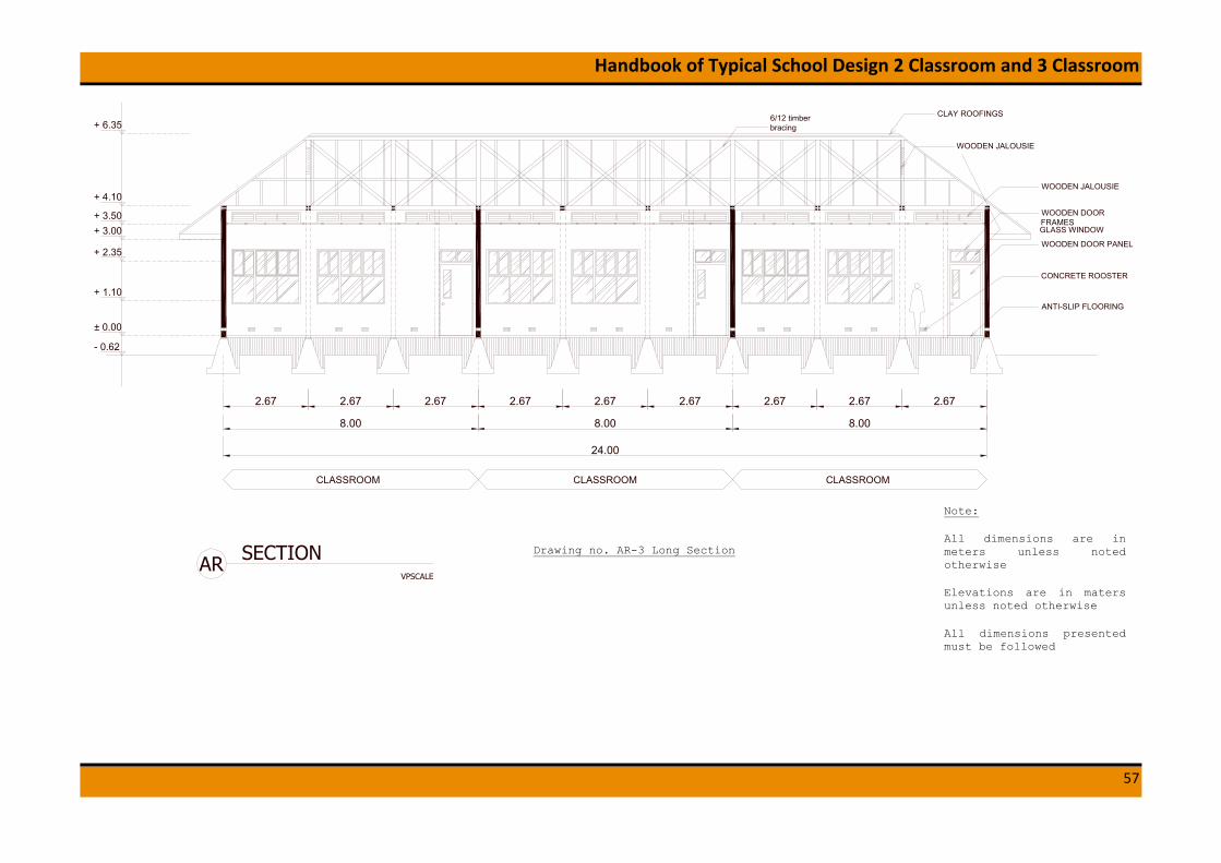
6/12 timberbracing
CLAY ROOFINGS
WOODEN JALOUSIE
WOODEN JALOUSIE
WOODEN DOORFRAMESGLASS WINDOW
WOODEN DOOR PANEL
ANTI-SLIP FLOORING
CONCRETE ROOSTER
± 0.00
+ 1.10
+ 2.35
+ 3.00+ 3.50
+ 4.10
+ 6.35
- 0.62
CLASSROOM
8.00 8.00 8.00
2.67 2.67 2.67 2.67 2.67 2.67 2.67 2.67 2.67
24.00
CLASSROOM CLASSROOM
VPSCALE
SECTIONAR
Drawing no. AR-3 Long Section
Note:
All dimensions are in meters unless noted otherwise
Elevations are in maters unless noted otherwise
All dimensions presented must be followed

Handbook of Typical School Design 2 Classroom and 3 Classroom
58
WOODENJALOUSIE
VPSCALE
SECTIONAR
1.00 0.60 2.50 7.00 1.20 0.9013.20
± 0.00
+ 1.10
+ 2.35
+ 3.00+ 3.50
+ 4.10
+ 6.35
- 0.62
TERRACE CLASSROOM EMERGENCYEXIT
WOODENJALOUSIE
METALHANDRAIL
PLANTER BOX
LOOSE PEBBLES
CLOSEDDRAINAGE SYSTEM
30°
VPSCALE
SECTIONAR
1.000.60 2.50 7.00 1.20 0.9013.20
± 0.00
+ 1.10
+ 2.35
+ 3.00+ 3.50
+ 4.10
+ 6.35
- 0.62
TERRACE CLASSROOM EMERGENCYEXIT
CLAY ROOFINGS
WOODENJALOUSIE
WOODENWINDOW PANEL
METALHANDRAIL
PLANTER BOX
LOOSE PEBBLES
CLOSEDDRAINAGE SYSTEM
30°
Drawing no. AR-4 Cross Section
Note:
All dimensions are in meters unless noted otherwise
Elevations are in maters unless noted otherwise
All dimensions presented must be followed

Handbook of Typical School Design 2 Classroom and 3 Classroom
59
4.2 Structural Drawings
C
B
A
D
E
24.00
TB1
TB1
TB1
TB1
TB1
TB1
TB1
TB1
TB1
TB1
TB1
TB1
TB1 TB1TB1 TB1TB1 TB1TB1TB1 TB1
2.33
7.0
0
TB1
TB1
TB1
TB1
TB1
TB1
TB1
TB1
TB1
TB1
TB1
TB1
TB1
TB1
TB1
TB1
TB1
TB1
TB1
TB1
TB1
TB1
TB1
TB1
TB1
TB1
TB1
2.672.672.67
2.672.672.672.67 2.67
8 9 10
TB1
TB1
TB1
TB1
TB1
TB1
TB1
TB1
TB1
TB1
TB1
TB1
TB1
TB1
TB1
TB1
TB1
TB1
TB1
TB1
TB1
TB1
TB1
2.67 2.67 2.67 2.67
2.67 2.67 2.67 2.67 2.67 2.672.
50
2.33
2.33
1 2 3 4 5 6 7
Tie Beam 15/15 cm (TB)Stone Masonry Foundation (PB)
Ramp, Lay OutSee architectural drawing
Stairs, Lay OutSee architectural drawing
TB1
TB1
TB1
TB1
TB1
TB1
TB1 TB1
TB1 TB1
B
B
SR-16
SR-16
A
ASR-16
SR-16DD
SR-17 S-021
1.12 1.55 1.12 1.55 1.12 1.55
1.351.32 1.351.32 1.351.32
TB1
TB1
TB1
TB1
TB1
TB1
TB1
TB1
TB1
TB1
TB1
TB1
TB1
TB1
TB1
TB1
TB1
TB1
TB1
TB1
TB1
TB1
TB1
TB1
TB1
TB1TB
1TB1
TB1
TB1
TB1
TB1
TB1
TB1
TB1
TB1
TB1
TB1
TB1
TB1
TB1
TB1
TB1
TB1
TB1
TB1
TB1
TB1
TB1
TB1
TB1
TB1
TB1
TB1
TB1
TB1
TB1
TB1
TB1
TB1
TB1
TB1
TB1
Drawing no. SR-1 Foundation Plan
Note:
All dimensions are in meters unless noted otherwise.
Elevations are in meters unless noted otherwise
All dimensions presented must be followed
Concrete Strength: K-225, Reinforcement Bar:
D ≥ 10 mm, fy = 3200 kg/cm2,
D < 10 mm, fy = 2400 kg/cm2

Handbook of Typical School Design 2 Classroom and 3 Classroom
60
1.12 1.55
1.351.32
1.12 1.55 1.12 1.55
1.351.32 1.351.32
K1 K1 K1
K1 K1 K1
Practical Column Plan (Elev. ±0.00)2
2.67 2.67 2.67 2.67
2.67 2.67 2.67 2.67 2.67 2.672.
50
2.33
2.33
1 2 3 4 5 6 7
2.33
7.0
02.672.672.67
2.672.672.672.67 2.67
8 9 10
C
B
A
D
E
24.00
K1
K1
K1
K1
K1
K1
K1
K1
K1
K1
K1
K1
K1
K1
K1
K1
K1
K1
K1
K1
K1
K1
K1
K1
K1
K1
K1
K1
K1
K1
K1
K1
K1
K1
K1
K1
K1
K1
Drawing no. SR-2 Practical Column Pl
Note:
All dimensions are in meters unless noted otherwise.
Elevations are in meters unless noted otherwise
All dimensions presented must be followed
Concrete Strength: K-225, Reinforcement Bar:
D ≥ 10 mm, fy = 3200 kg/cm2,
D < 10 mm, fy = 2400 kg/cm2

Handbook of Typical School Design 2 Classroom and 3 Classroom
61
2.67 2.67 2.67 2.67
2.67 2.67 2.67 2.67 2.67 2.672.
50
2.33
2.33
1 2 3 4 5 6 7
2.33
7.0
02.672.672.67
2.672.672.672.67 2.67
8 9 10
C
B
A
D
E
24.00
1.351.32 1.351.32 1.351.32
Lintel Beam & Ring Beam Plan (Elev. +2.55)3
K1
K1
K1
K1
K1
K1
K1
K1
K1
K1
K1
K1
K1
K1
K1
K1
K1
K1
K1
K1
K1
K1
K1
K1
K1
K1
K1
K1
K1
K1
K1
K1
K1
K1
K1
K1
K1
K1
RB RB RB RB RB RB RB RB RB RB
RBRBRBRBRBRBRBRBRB
BLBLBLBLBLBLBLBLBL
BL
BL
BL
BL
BL
BL
BL
BL
BL
BL
BL
BL
BLBLBLBLBLBLBLBLBL
Drawing no. SR-3 Lintel Beam & Ring Beam Plan
Note:
All dimensions are in meters unless noted otherwise.
Elevations are in meters unless noted otherwise
All dimensions presented must be followed
Concrete Strength: K-225, Reinforcement Bar:
D ≥ 10 mm, fy = 3200 kg/cm2,
D < 10 mm, fy = 2400 kg/cm2

Handbook of Typical School Design 2 Classroom and 3 Classroom
62
2.67 2.67 2.67 2.67
1 2 3 4 5 6 72.672.672.672.67 2.67
8 9 10
24.00
Ring Beam Plan (Elev. +3.71)4
2.67 2.67 2.67 2.67 2.67 2.67
2.33
2.33
2.33
7.0
02.672.672.67
C
B
A
DK1
K1
K1
K1
K1
K1
K1
K1
K1
K1
K1
K1
K1
K1
K1
K1
K1
K1
K1
K1
K1
K1
K1
K1
K1
K1
K1
K1
RBRBRBRBRBRBRBRBRB
RB
RB
RB
RB
RB
RB
RB
RB
RB
RB
RB
RB
RBRBRBRBRBRBRBRBRB
Drawing no. SR-4 Ring Beam Plan
Note:
All dimensions are in meters unless noted otherwise.
Elevations are in meters unless noted otherwise
All dimensions presented must be followed
Concrete Strength: K-225, Reinforcement Bar:
D ≥ 10 mm, fy = 3200 kg/cm2,
D < 10 mm, fy = 2400 kg/cm2

Handbook of Typical School Design 2 Classroom and 3 Classroom
63
2.67 2.67 2.67 2.67
1 2 3 4 5 6 72.672.672.672.67 2.67
8 9 10
24.00
Ø 10
− 2
00
Ø 10 − 200
Y
Y
X X
Ø 10 − 200 Ø 10 − 200 Ø 10 − 200 Ø 10 − 200 Ø 10 − 200 Ø 10 − 200
Ø 10 − 200 Ø 10 − 200 Ø 10 − 200 Ø 10 − 200 Ø 10 − 200 Ø 10 − 200 Ø 10 − 200
Ø 10
− 2
00
Ø 10
− 2
00
Ø 10
− 2
00
Slab Reinforcement (Elev. ± 0.00)5
2.67 2.67 2.67 2.67 2.67 2.672.
50
2.33
2.33
2.33
7.0
02.672.672.67
C
B
A
D
E
Ø 10 − 200 Ø 10 − 200 Ø 10 − 200 Ø 10 − 200 Ø 10 − 200 Ø 10 − 200 Ø 10 − 200
Ø 10 − 200 Ø 10 − 200 Ø 10 − 200 Ø 10 − 200 Ø 10 − 200 Ø 10 − 200 Ø 10 − 200
Ø 10
− 2
00
Ø 10
− 2
00
Ø 10
− 2
00
Ø 10
− 2
00
Ø 10
− 2
00
Ø 10
− 2
00
Ø 10
− 2
00
Ø 10
− 2
00
Ø 10
− 2
00
Ø 10
− 2
00
Ø 10
− 2
00
Ø 10
− 2
00
Ø 10
− 2
00
Ø 10
− 2
00
Drawing no. SR-5 Slab Reinforcement
Note:
All dimensions are in meters unless noted otherwise.
Elevations are in meters unless noted otherwise
All dimensions presented must be followed
Concrete Strength: K-225, Reinforcement Bar:
D ≥ 10 mm, fy = 3200 kg/cm2,
D < 10 mm, fy = 2400 kg/cm2

Handbook of Typical School Design 2 Classroom and 3 Classroom
64
2.67 2.67 2.67 2.67
1 2 3 4 5 6 72.672.672.672.67 2.67
8 9 10
24.00
1 2 3 4 5 6 10
E
C
B
A
1 2 3 4 5 6 10
E
C
B
A
Reinforcement Plan 6
2.67 2.67 2.67 2.67 2.67 2.672.
50
2.33
2.33
2.33
7.0
02.672.672.67
C
B
A
D
E
DD
7
7
8
8
9
9
Drawing no. SR-6 Reinforcement Plan
Note:
All dimensions are in meters unless noted otherwise.
Elevations are in meters unless noted otherwise
All dimensions presented must be followed
Concrete Strength: K-225, Reinforcement Bar:
D ≥ 10 mm, fy = 3200 kg/cm2,
D < 10 mm, fy = 2400 kg/cm2

Handbook of Typical School Design 2 Classroom and 3 Classroom
65
Stone Masonry Foundation - Detail (PB)9
Stone Gravel 10 cmCompacted Sand 5 cm
Ø 10 − 200
-0.55GROUND LEVEL
0.15
0.0
5
AanstampingCompacting Sand
Stone Masonry FoundationCompacting Soil Filling
±0.00
Anchor 10 - 1000
Tie Beam 15/15 cmConcrete Floor Slab of Thickness 12 cm
0.80
0.5
5
Hard Soil
100 Year flood level
D 13 - 100
D 1
3 -
100
1.00
0.15
1.00
0.15
1.00
0.3
00
.10
D 13 − 100
D 13 − 100
0.0
50
.15
D 13 − 100
Compacted Soil
0.15
Ø 10 − 200
0.5
5
±0.00
-0.55 GROUND LEVEL
0.2
0
Z Z
Local Footings (needed to meet deep hard soil level)8
Foot Plate Foundation Plan7
Concrete Floor Slab of Thickness 12 cmStone Gravel 10 cmCompacted Sand 5 cm
AanstampingCompacting SandHard Soil
conc
rete
cov
er m
in 7
cm
Drawing no. SR-7 Foundation Detail
Note:
All dimensions are in meters unless noted otherwise.
Elevations are in meters unless noted otherwise
All dimensions presented must be followed
Concrete Strength: K-225, Reinforcement Bar:
D ≥ 10 mm, fy = 3200 kg/cm2,
D < 10 mm, fy = 2400 kg/cm2

Handbook of Typical School Design 2 Classroom and 3 Classroom
66
45°
45°
45°min 6 cm
2,33
B2,33
K1' K1'
K1 K1
K1' K1'
K1 K1
TB1'
TB1'
TB1
TB1
RB'
RB'
RB
RB
BL'
BL'
BL
BL
TB1'
TB1'
TB1
TB1
RB'
RB'
RB
RB
BL'
BL'
BL
BL
K1'K1'
K1K1
2 Ø8 - 1000
Reinforcement Grid 1,4,7 & 1012
Detail Foundation Anchor D10-1000mm11
Detail Wall Anchor Ø8-1000mm10
Detail C15Detail B14
4,10
+2.55
±0.00
0,15
+4.10
1,40
GROUND LEVEL−0.55
0,55
2,55
0.2
0
> 65
.d
> 12.d
> 6.d
> 5.d
45°
90°
K1' K1'
K1 K1
RB'
RB'
RB
RB
BL'
BL'
BL
BL
K1' K1'
K1 K1
RB'
RB'
RB
RB
TB1'
TB1'
TB1
TB1
2,50 2,33
E D C A
0,15TB1'
TB1'
TB1
TB1
Min.
40
cm
min 6 cm
Min. 40 cm
C
B
HARD SOIL
100 YEAR FLOOD LEVEL
A
2 Ø8 - 1000
2 Ø8 2 Ø8 2 Ø8
1,00
Detail A13
Min. 40 cm
Min.
40
cm
min 6 cm
Min.
40
cm
minim
um 8
0 c
m
2 Ø8 - 1000
1,00 1,00 1,00 1,00 1,00 1,00 1,00 1,00
Drawing no. SR8 Reinforcement Grid 1, 4, 7 & 10
Note:
All dimensions are in meters unless noted otherwise.
Elevations are in meters unless noted otherwise
All dimensions presented must be followed
Concrete Strength: K-225, Reinforcement Bar:
D ≥ 10 mm, fy = 3200 kg/cm2,
D < 10 mm, fy = 2400 kg/cm2

Handbook of Typical School Design 2 Classroom and 3 Classroom
67
minim
um 8
0 c
m
K1' K1'K1'
K1K1
TB1'
TB1'
4,10
+2.55
±0.00
0,15
+4.10
1,40
−0.55
0,55
2,55
TB1
TB1
K1'
K1 K1
K1' K1'
K1 K1
RB'
RB'
RB
RB
TB1'
TB1'
TB1
TB1
2,50 7,00
E D A0,
15
Reinforcement Grid 2,3,5,6,8 & 917
Detail Foundation Anchor D10-1000mm16
> 65
.d
> 12.d
> 6.d
> 5.d
45°
GROUND LEVEL
HARD SOIL
100 YEAR FLOOD LEVEL
1,00 1,00 1,00 1,00
Anchor 10 - 1000
Drawing no. SR-9 Reinforcement Grid 2, 3, 5, 6, 8, & 9
Note:
All dimensions are in meters unless noted otherwise.
Elevations are in meters unless noted otherwise
All dimensions presented must be followed
Concrete Strength: K-225, Reinforcement Bar:
D ≥ 10 mm, fy = 3200 kg/cm2,
D < 10 mm, fy = 2400 kg/cm2

Handbook of Typical School Design 2 Classroom and 3 Classroom
68
minim
um 8
0 c
m
RB
BL'
BL'
BL
BL
TB1'
TB1'TB1
TB1−0.55
RB'
RB'
RB
RB
BL'
BL'
BL
BL
TB1'
TB1'TB1
TB1
RB'
RB'
RB
RB
BL'
BL'
BL
BL
TB1'
TB1'TB1
TB1
RB'
RB'
RB
RB
BL'
BL'
BL
BL
TB1'
TB1'TB1
TB1
RB'
RB'
RB
TB1'
TB1'TB1
TB1
K1 K1
K1' K1'
K1 K1
K1' K1'
2,67
62,67
5
RB'
RB'
RB
RB
BL'
BL'
BL
BL
2,67
92,67
K1' K1'
K1 K1
K1' K1'
4,10
+2.55
±0.00
0,15
+4.10
1,40
0,55
2,55K1'K1'
K1K1
K1' K1'
K1 K1K1 K1
2,67
7 8 10
0,15
Reinforcement Grid A & D (Continue)20
Detail Foundation Anchor D10-1000mm19Detail Wall Anchor Ø8-1000mm18
2 Ø8 2 Ø8 2 Ø8 2 Ø82 Ø8
1,00
K1'K1'
K1K1
2 Ø8
K1'K1'
K1K1
> 65
.d
> 12.d
> 6.d
> 5.d
45°0.2
090°
GROUND LEVEL
HARD SOIL
100 YEAR FLOOD LEVEL
1,00 1,00 1,00 1,00 1,00 1,00 1,00 1,00 1,00 1,00
Drawing no. SR-10 Reinforcement Grid A & D (Continue)
Note:
All dimensions are in meters unless noted otherwise.
Elevations are in meters unless noted otherwise
All dimensions presented must be followed
Concrete Strength: K-225, Reinforcement Bar:
D ≥ 10 mm, fy = 3200 kg/cm2,
D < 10 mm, fy = 2400 kg/cm2

Handbook of Typical School Design 2 Classroom and 3 Classroom
69
minim
um 8
0 c
m2,67
22,67
4,10
+2.55
±0.00
0,15
+4.10
1,40
0,55
2,55
2,67
431
0,15
Detail Foundation Anchor D10-1000mm22Detail Wall Anchor Ø8-1000mm21
2 Ø8 2 Ø8
1,00
2 Ø8
K1'K1'
K1K1
> 65
.d
> 12.d
> 6.d
> 5.d
45°0.2
090°
HARD SOIL
GROUND LEVEL
100 YEAR FLOOD LEVEL
−0.55
K1 K1
K1' K1'
K1 K1
K1' K1'
K1 K1
K1' K1'
K1 K1
K1' K1'2 Ø8
RB'
RB'
RB
RB
BL'
BL'
BL
BL
TB1'
TB1'TB1
TB1
RB'
RB'
RB
RB
BL'
BL'
BL
BL
TB1'
TB1'TB1
TB1
RB'
RB'
RB
RB
BL'
BL'
BL
BL
TB1'
TB1'TB1
TB1
1,00 1,00 1,00 1,00 1,00 1,00
Reinforcement Grid A & D23 Drawing no. SR-11 Reinforcement Grid A & D
Note:
All dimensions are in meters unless noted otherwise.
Elevations are in meters unless noted otherwise
All dimensions presented must be followed
Concrete Strength: K-225, Reinforcement Bar:
D ≥ 10 mm, fy = 3200 kg/cm2,
D < 10 mm, fy = 2400 kg/cm2

Handbook of Typical School Design 2 Classroom and 3 Classroom
70
Reinforcement Grid B & C (Continue)25
Detail Foundation Anchor D10-1000mm24
> 65
.d
> 12.d
> 6.d
> 5.d
45°
GROUND LEVEL
HARD SOIL
100 YEAR FLOOD LEVEL
minim
um 8
0 c
m
K1 K1
2,67
7 8 10
0,15
±0.00
0,15
+4.10
0,55
3,95
K1'K1'
K1K1
2,67
92,67
K1' K1'
2,67
62,67
5
TB1'
TB1'TB1
TB1−0.55
TB1'
TB1' TB1
TB1
1,00 1,001,00
Anchor 10 - 1000 Anchor 10 - 1000
Drawing no. SR-12 Reinforcement Grid B & C (Continue)
Note:
All dimensions are in meters unless noted otherwise.
Elevations are in meters unless noted otherwise
All dimensions presented must be followed
Concrete Strength: K-225, Reinforcement Bar:
D ≥ 10 mm, fy = 3200 kg/cm2,
D < 10 mm, fy = 2400 kg/cm2

Handbook of Typical School Design 2 Classroom and 3 Classroom
71
minim
um 8
0 c
m
Reinforcement Grid B & C27
Detail Foundation Anchor D10-1000mm26
> 6
5.d
> 12.d
> 6.d
> 5.d
45°
GROUND LEVEL
100 YEAR FLOOD LEVEL
HARD SOIL
2,67
431
0,15
±0.00
0,15
+4.10
0,55
3,95
2,67
22,67
−0.55
K1 K1
K1' K1'
K1 K1
K1' K1'
TB1'
TB1'TB1
TB1 TB1'
TB1'TB1
TB1
1,00 1,00
Anchor 10 - 1000
Drawing no. SR-13 Reinforcement Grid B & C
Note:
All dimensions are in meters unless noted otherwise.
Elevations are in meters unless noted otherwise
All dimensions presented must be followed
Concrete Strength: K-225, Reinforcement Bar:
D ≥ 10 mm, fy = 3200 kg/cm2,
D < 10 mm, fy = 2400 kg/cm2

Handbook of Typical School Design 2 Classroom and 3 Classroom
72
Detail Foundation Anchor D10-1000mm28
Reinforcement Grid E (Continue)29
> 65
.d
> 12.d
> 6.d
> 5.d
45°
minim
um 8
0 c
m
GROUND LEVEL
HARD SOIL
100 YEAR FLOOD LEVEL
K1 K1
2,67
7 8 10
0,15
+2.55
±0.00
0,15
0,55
2,55K1'K1'
K1K1
K1' K1'
K1 K1
RB'
RB'
RB
RB
2,67
92,67
K1' K1'
K1 K1
K1' K1'
K1 K1
K1' K1'
K1 K1
K1' K1'
2,67
62,67
5
TB1'
TB1'TB1
TB1
RB'
RB'
RB
RB
TB1'
TB1'TB1
TB1
RB'
RB'
RB
RB
TB1'
TB1'TB1
TB1
RB'
RB'
RB
RB
TB1'
TB1'TB1
TB1
RB'
RB'
RB
RB
TB1'
TB1'TB1
TB1−0.55
1,00 1,001,00 1,001,00 1,001,00 1,001,00 1,00
Drawing no. SR-14 Reinforcement Grid E(Continue)
Note:
All dimensions are in meters unless noted otherwise.
Elevations are in meters unless noted otherwise
All dimensions presented must be followed
Concrete Strength: K-225, Reinforcement Bar:
D ≥ 10 mm, fy = 3200 kg/cm2,
D < 10 mm, fy = 2400 kg/cm2

Handbook of Typical School Design 2 Classroom and 3 Classroom
73
Detail Foundation Anchor D10-1000mm30
Reinforcement Grid E31
> 65
.d
> 12.d
> 6.d
> 5.d
45°
minim
um 8
0 c
m
GROUND LEVEL
100 YEAR FLOOD LEVEL
HARD SOIL
2,67
431
0,15
+2.55
±0.00
0,15
0,55
2,55
2,67
22,67
−0.55
K1 K1
K1' K1'
K1 K1
K1' K1'
K1 K1
K1' K1'
K1 K1
K1' K1'
RB'
RB'
RB
RB
TB1'
TB1'TB1
TB1
RB'
RB'
RB
RB
TB1'
TB1'TB1
TB1
RB'
RB'
RB
RB
TB1'
TB1'TB1
TB1
1,00 1,001,00 1,001,00 1,00
Drawing no. SR-15 Reinforcement Grid E
Note:
All dimensions are in meters unless noted otherwise.
Elevations are in meters unless noted otherwise
All dimensions presented must be followed
Concrete Strength: K-225, Reinforcement Bar:
D ≥ 10 mm, fy = 3200 kg/cm2,
D < 10 mm, fy = 2400 kg/cm2

Handbook of Typical School Design 2 Classroom and 3 Classroom
74
0,800,800,80Hard Soil
Hard Soil
100 YEAR FLOOD LEVEL
minimum 80 cm
Ø 10 − 200Ø 10 − 200
Concrete Floor Slab of Thickness 12 cmStone Gravel 10 cm
Compacted Sand 5 cm
Ø 10 − 200Ø 10 − 200Ø 10 − 200Concrete Floor Slab of Thickness 12 cm
Stone Gravel 10 cmCompacted Sand 5 cm
Hard Soil
Concrete Floor Slab of Thickness 12 cmStone Gravel 10 cm
Compacted Sand 5 cm
Hard Soil
Concrete Floor Slab of Thickness 12 cmStone Gravel 10 cm
Compacted Sand 5 cm
Hard Soil Hard Soil
Concrete Floor Slab of Thickness 12 cmStone Gravel 10 cm
Compacted Sand 5 cm
Concrete Floor Slab of Thickness 12 cmStone Gravel 10 cm
Compacted Sand 5 cm
Hard Soil Hard Soil Hard Soil Hard Soil
2,67
Sloof 15/15 cm Sloof 15/15 cm
Stone Masonry Foundation
Sloof 15/15 cm
Stone Masonry Foundation
0,80
4 5
Sloof 15/15 cm
Stone Masonry Foundation
0,80
2,672,67
1098
2,67
GROUND LEVEL
0,800,80
2,670,800,80
76
Sloof 15/15 cm
Stone Masonry Foundation
0,80
Sloof 15/15 cm
Stone Masonry Foundation
Sloof 15/15 cm
Stone Masonry Foundation
Sloof 15/15 cm
Stone Masonry Foundation
Sloof 15/15 cm
Stone Masonry Foundation
Ø 10 − 200
GROUND LEVELStone Masonry Foundation
2,67 2,67
1 2 3
Sloof 15/15 cm
2,67
Floor Reinforcement Section X-X (Elev. -0.03)32
Stone Masonry Foundation
Ramp Detail (Section B-B from SR-1)34Stairs Detail (Section A-A from SR-1)33
Ø 10 − 2000,20
0,05
0,15
0,50
0,12
-0.55 GROUND LEVEL
0,20
0,50
Stone Masonry FoundationAanstamping
Compacted Sand
0,50
Stone Masonry FoundationAanstamping
Compacted Sand0,05
0,15
0,37
0,20
0,25
0,15
0,15
-0.75
-0.55GROUND LEVEL
Ø 10 − 200
1 x Ø 8
1 x Ø 8
0,50
Compacted Soil Filling
Stone Masonry FoundationAanstamping
Compacted Sand
0,30
0,30
Hard Soil
Hard Soil
Hard Soil
Drawing no. SR-16 Floor Reinforcement Section X-X
Note:
All dimensions are in meters unless noted otherwise.
Elevations are in meters unless noted otherwise
All dimensions presented must be followed
Concrete Strength: K-225, Reinforcement Bar:
D ≥ 10 mm, fy = 3200 kg/cm2,
D < 10 mm, fy = 2400 kg/cm2

Handbook of Typical School Design 2 Classroom and 3 Classroom
75
Hard Soil
100 YEAR FLOOD LEVEL
minimum 80 cm
Ø 10 − 200Ø 10 − 200Concrete Floor Slab of Thickness 12 cmStone Gravel 10 cmCompacted Sand 5 cm
Concrete Floor Slab of Thickness 12 cmStone Gravel 10 cmCompacted Sand 5 cm
Concrete Floor Slab of Thickness 12 cmStone Gravel 10 cmCompacted Sand 5 cm
Hard SoilHard SoilHard SoilHard Soil
Sloof 15/15 cm
Stone Masonry Foundation
0,80
Sloof 15/15 cm
Stone Masonry Foundation
0,80
Sloof 15/15 cm
Stone Masonry Foundation
0,80
Sloof 15/15 cm
Stone Masonry Foundation
0,80
Sloof 15/15 cm
Stone Masonry Foundation
0,80
D
2,332,50 2,33
E C B A2,33
GROUND LEVEL GROUND LEVEL
Ø 10 − 200
Floor Reinforcement Section Y-Y ( Elev. - 0.03)36
Stone Masonry FoundationAanstamping
Compacted Sand
0,50
Ø 10 − 200
Compacted Soil Filling
Hard Soil
Drawing no.SR-17 Floor Reinforcement Section Y-Y
Note:
All dimensions are in meters unless noted otherwise.
Elevations are in meters unless noted otherwise
All dimensions presented must be followed
Concrete Strength: K-225, Reinforcement Bar:
D ≥ 10 mm, fy = 3200 kg/cm2,
D < 10 mm, fy = 2400 kg/cm2

Handbook of Typical School Design 2 Classroom and 3 Classroom
76
2 D 10 mm 2 D 10 mm
2 D 10 mm
Ø 8 - 100 mm Ø 8 - 150 mm
2 D 10 mm
2 D 10 mm 2 D 10 mm
2 D 10 mm
NOTATION
B x D
TOP BAR
BOTTOM BARSTRIRRUP
END MID
Ø 8 - 100 mm
15 x 15 cm
Ø 8 - 150 mm
SECTION
0.15
0.15
0.025
0.0
25
LIST OF TIE BEAM
POSITION
TB1 TB1'
WEB BAR
NOTE
2 D 10 mm
LIST OF RING BEAM
0.025
0.0
25
0.06
0.15
0.15
0.025
0.0
25
0.025
0.0
25
0.06
NOTATION
B x D
TOP BAR
BOTTOM BARSTRIRRUP
END MID
15 x 15 cm
SECTION
0.15
0.15
0.025
0.0
25
POSITION
RB RB'
WEB BAR
NOTE
0.025
0.0
25
0.06
0.15
0.15
0.025
0.0
25
0.025
0.0
25
0.06
Ø 8 - 100 mm Ø 8 - 150 mm
2 D 10 mm
2 D 10 mm 2 D 10 mm
2 D 10 mm
NOTATION
B x D
TOP BAR
BOTTOM BARSTRIRRUP
END MID
15 x 15 cm
SECTION
LIST OF LINTEL BEAM
POSITION
BL BL'
WEB BAR
NOTE
NOTATION
B x D
MAIN BARSTRIRRUP
END MID
Ø 8 - 100 mm
15 x 15 cm
Ø 8 - 150 mm
SECTION
LIST OF PRACTICAL COLUMN
POSITION
K1 K1'
4 D 10 mm 4 D 10 mm
NOTE
0.15
0.15
0.025
0.0
25
0.025
0.0
25
0.06
0.15
0.15
0.025
0.0
25
0.025
0.0
25
0.06
0.15
0.15
0.025
0.0
25
0.025
0.0
25
0.06
0.15
0.15
0.025
0.0
25
0.025
0.0
25
0.06
Reinforcement Detail for Building B&D39
Drawing no. SR-18 Reinforcement Detail
Note:
All dimensions are in meters unless noted otherwise.
Elevations are in meters unless noted otherwise
All dimensions presented must be followed
Concrete Strength: K-225, Reinforcement Bar:
D ≥ 10 mm, fy = 3200 kg/cm2,
D < 10 mm, fy = 2400 kg/cm2

Handbook of Typical School Design 2 Classroom and 3 Classroom
77
40 D Lap SpliceTop Bar Only
12 L
14 L
40 D Lap SpliceBottom Bar Only
Top Steel Splices Shall Only Be Locatedat Mid Span (L/2)
Bottom Steel Splices Shall Only Be Locatedat Quarter Span (L/4)
20/80 Crank
20/80 Crank
Provide Stirrupsat 75 CTRS OverLength of Splices
Provide Stirrupsat 75 CTRS OverLength of Splices
L
Permissible Beam Splice locations40
Drawing no. SR-19 Permissible Beam Splice Locations
Note:
All dimensions are in meters unless noted otherwise.
Elevations are in meters unless noted otherwise
All dimensions presented must be followed
Concrete Strength: K-225, Reinforcement Bar:
D ≥ 10 mm, fy = 3200 kg/cm2,
D < 10 mm, fy = 2400 kg/cm2

Handbook of Typical School Design 2 Classroom and 3 Classroom
78
PracticalColumn
Ln
Ln/4Support
L
Permissible Beam & Column Stirrup locations41
Ln/4Support
Ln/2Middle
Ln
Ln/4Support
Ln/4Support
Ln/2Middle
Ln
Ln/4
Sup
port
Ln/4
Sup
port
Ln/2
Mid
dle
Beam
PracticalColumn
Tie Beam
Drawing no. SR-20 Permissible Beam & Column Stirrups Locations
Note:
All dimensions are in meters unless noted otherwise.
Elevations are in meters unless noted otherwise
All dimensions presented must be followed
Concrete Strength: K-225, Reinforcement Bar:
D ≥ 10 mm, fy = 3200 kg/cm2,
D < 10 mm, fy = 2400 kg/cm2

Handbook of Typical School Design 2 Classroom and 3 Classroom
79
Roof Truss Plan49
1.45
7.0
03.
95
1.45 24.00 1.45
0.50 0.50
0.50
Drawing no. SR-21 Roof Truss Plan
Note:
All dimensions are in meters unless noted otherwise.
Elevations are in maters unless noted otherwise
All dimensions presented must be followed
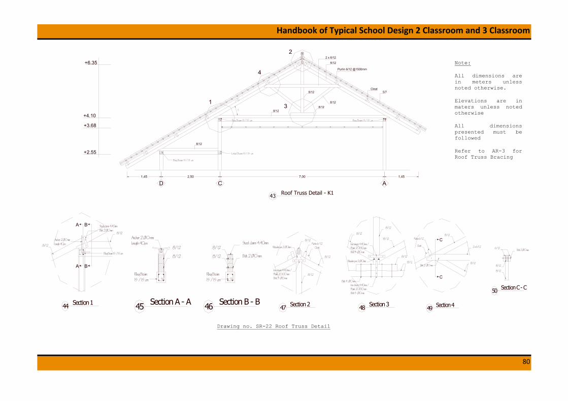
Handbook of Typical School Design 2 Classroom and 3 Classroom
80
Purlin 6/12 @1500mm
8/12
5/7
18/12
Cleat
8/12
2 x 6/12
8/12
8/12
2
3
4
30°
8/12
7,002,50 1,451,45
Roof Truss Detail - K143
+4.10
+3.68
+6.35
+2.55
ACD
Ring Beam 15/15 cm
Lintel Beam 15/15 cm
Ring Beam 15/15 cm Ring Beam 15/15 cm
Section 144
RIng Beam 15 /15 cm
Steel clams 4.40mmBolt 2 Ø10 mm
Anchor 2 Ø10 mmlength 40cm
8/12
8/12
A
A
B
B
Anchor 2 Ø10 mmlength 40cm
Section A - A45 Section B - B46
Steel clams 4.40mm
Bolt 2 Ø10 mm8/12
8/12
8/12
8/12
RIng Beam15 /15 cm
RIng Beam15 /15 cm
8/12
Purlin 6/12Cleat
8/12Iron sheet 4.40mm /Plank 20.100 mmBolt 3 Ø10 mm
Wooden pin 2 Ø10mm
Section 247
8/12
8/12
8/12
8/12
8/12
Iron sheet 4.40mm /Plank 20.100 mmBolt 3 Ø10 mm
Bolt 4 Ø10 mm
Iron sheet 4.40mm /Plank 20.100 mmBolt 3 Ø10 mm
Wooden pin 2 Ø10mm
Section 348
8/12
2 x 6/12
8/12
8/12Purlin 6/12
Cleat
Bolt 2 Ø10 mm
C
C
Bolt 2 Ø10 mm
8/12
8/12
6/12
Section 449
Section C - C50
Note:
All dimensions are in meters unless noted otherwise.
Elevations are in maters unless noted otherwise
All dimensions presented must be followed
Refer to AR-3 for Roof Truss Bracing
Drawing no. SR-22 Roof Truss Detail
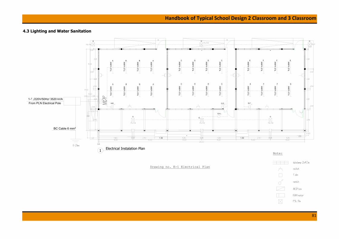
Handbook of Typical School Design 2 Classroom and 3 Classroom
81
4.3 Lighting and Water Sanitation
0.15
2.35
0.50
0.15
1.00
0.15
3.850.252.403.850.253.852.400.253.80
0.15
0.15
2.18
0.15
2.30
4.004.004.004.004.004.00
3.50
3.50
1.080.15
1.22
24.00
9.50
1.501.50
TLD
1x3
6WTL
D 1
x36W
A
A
TLD
1x3
6WTL
D 1
x36W
B
B
TLD
1x3
6WTL
D 1
x36W
B
B
TLD
1x3
6WTL
D 1
x36W
A
A
TLD
1x3
6WTL
D 1
x36W
C
TLD
1x3
6WTL
D 1
x36W
D
TLD
1x3
6WTL
D 1
x36W
D
TLD
1x3
6WTL
D 1
x36W
C
C D D C
TLD
1x3
6WTL
D 1
x36W
E
TLD
1x3
6WTL
D 1
x36W
F
TLD
1x3
6WTL
D 1
x36W
F
TLD
1x3
6WTL
D 1
x36W
E
E F F E
C,D
PSL 9 W
G
PSL 9 W
G
PSL 9 W
G
PSL 9 WH
PSL 9 W
H
PSL 9
H
G,H
A,B E,FMDP
From PLN Electrical Pole1-? ,/220V/50Hz/ 3520 kVA
5 Ohm
BC Cable 6 mm²
Scale: 1:100
Electrical Instalation Plan1
0.15
2.18
0.15
2.18
2.18
0.15
2.18
0.15
2.18
0.15
Drawing no. E-1 Electrical Plan
Note:
tubelamp 2x40w
socket
T dos
switch
MCB box
KWH meter
PSL 9w

Handbook of Typical School Design 2 Classroom and 3 Classroom
82
0.90
zincallume metal roof
6/126/12
6/126/12
wooden trust 5/12water tank 1m312cm concrete slab4mm plywood
5/10
metal plate
2/30
painted walltile 20/25tile 20/2012cm concrete slab
water tap
paintedwall
paintedwall
paintedwall
tile20/25
tile20/25
tile20/25
±0.00 = 10,596
−0.18 = 10,416
2.50
0.16
1.02
0.60
0.18
−0.28
1.37
+0.13±0.00
+0.13 +0.13
paintedwall
tile20/25
water tank1000lt
4mm plywood
0.90 0.90 1.20 1.00
0.05 0.10
0.53
0.270.16
1.37
1.00
0.20
1.15
0.20
1.41
−0.18±0.00+0.13
−0.98−0.83
+2.60
+3.95
+5.46
0.30
0.60
Scale: 1:50
Section 1-12
4.90
A C E
0.10
0.60
0.10
Ø1"pipe
Ø1"pipe
Ø1"pipeØ 1
2 "pipeØ 1
2 "pipeØ 12 "pipe
Ø 12 "pipe
Ø 12 "pipe
Ø 12 "pipe
Ø 12 "pipe
Ø 12 "pipe
water tank 1000Ltwater tank 1000Lt
Scale: 1:50
Ceiling Piping Plan1
1
1.00
2 3 4 5
1.50 1.50 1.00
0.90
0.90
0.90
1.20
Ø1"pipeØ 12 "pipe
Ø1"pipe
Ø 12 "pipe Ø 1
2 "pipe Ø 12 "pipe Ø 1
2 "pipe
Drawing no. WS-1 Ceiling Piping Plan & Section 1-1

Handbook of Typical School Design 2 Classroom and 3 Classroom
83
painted wall
tile 20/25
painted wall
tile 20/25
painted wall
tile 20/25
painted wall
tile 20/25
±0.00 −0.02+0.13
−0.02+0.13
water tank1000lt
water tank1000lt
0.050.10
0.60
0.150.16
1.37
1.02
0.020.18
1.15
0.20
−0.18±0.00+0.13
−0.98−0.83
+2.60
+3.95
0.34
1.00
0.100.60
0.10
0.05
5.001.001.00
0.60
0.150.15
1.90
1 3 5
Scale: 1:50
Section 2-23
0.95
1.41
+5.70
painted wall
tile 20/25
water tank1000lt
water tank1000lt
0.050.10
0.60
0.150.16
1.37
1.020.02
0.18
1.15
0.20
−0.18±0.00+0.13
−0.98−0.83
+2.60
+3.95
2.50 2.50
0.10 0.60 0.10
0.05
0.15
0.13
0.03
5.001.001.00
1 3 5
Scale: 1:50
Section 3-34
0.850.50
0.30
0.70
painted wall
tile 20/25
7.00
0.95
1.41
+5.707.00
zincallume metal roofwooden trust 5/12water tank 1m312cm concrete slab4mm plywood
painted walltile 20/25tile 20/20squat closet12cm concrete slab
5/10 5/105/10
5/10
5/10 5/10 5/10 5/10
water tapwater tap water tapwater basinwater basin
zincallume metal roofwooden trust 5/12water tank 1m312cm concrete slab4mm plywood
±0.00 = 10,596
−0.28 −0.28
1.00
4mm plywood9mm gypsum board & hollow 40/40/2
painted walltile 20/25tile 20/2012cm concrete slab
−0.18 = 10,416
±0.00 = 10,596
−0.18 = 10,416
±0.00 = 10,596
0.73 0.78 0.78 0.73 1.00
Ø 12 "pipe
Ø1"pipe Ø1"pipe Ø1"pipe Ø1"pipe
Ø 12 "pipe Ø 1
2 "pipe Ø 12 "pipe
Ø 12 "pipe
4mm plywood 4mm plywood
Drawing no. WS-2 Section 2-2 & Section 3-3

Handbook of Typical School Design 2 Classroom and 3 Classroom
84
1.20
0.90
0.90
0.90
1.00 0.60 0.90 1.490.99
Toilet Plan5
Drawing no. WS-3 Toilet Plan
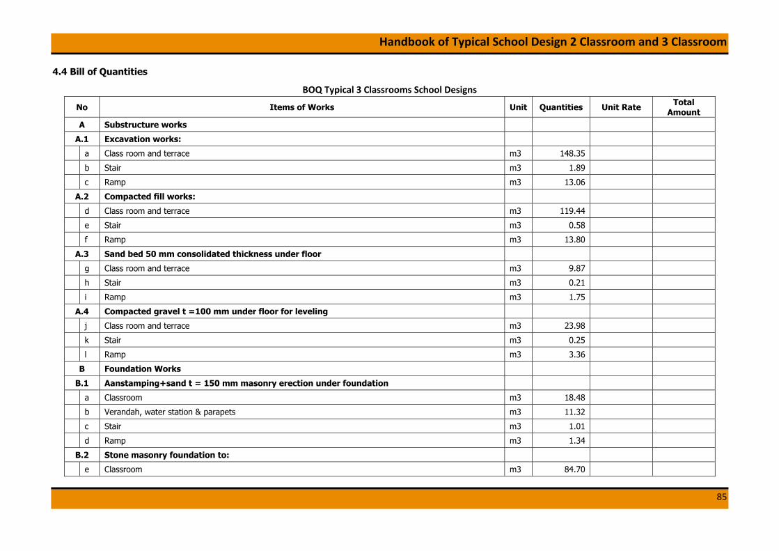
Handbook of Typical School Design 2 Classroom and 3 Classroom
85
4.4 Bill of Quantities
BOQ Typical 3 Classrooms School Designs
No Items of Works Unit Quantities Unit Rate Total Amount
A Substructure works
A.1 Excavation works:
a Class room and terrace m3 148.35
b Stair m3 1.89
c Ramp m3 13.06
A.2 Compacted fill works:
d Class room and terrace m3 119.44
e Stair m3 0.58
f Ramp m3 13.80
A.3 Sand bed 50 mm consolidated thickness under floor
g Class room and terrace m3 9.87
h Stair m3 0.21
i Ramp m3 1.75
A.4 Compacted gravel t =100 mm under floor for leveling
j Class room and terrace m3 23.98
k Stair m3 0.25
l Ramp m3 3.36
B Foundation Works
B.1 Aanstamping+sand t = 150 mm masonry erection under foundation
a Classroom m3 18.48
b Verandah, water station & parapets m3 11.32
c Stair m3 1.01
d Ramp m3 1.34
B.2 Stone masonry foundation to:
e Classroom m3 84.70

Handbook of Typical School Design 2 Classroom and 3 Classroom
86
f Verandah, water station & parapets m3 39.39
g Stair m3 3.36
h Ramp m3 1.96
C Anchorage
a Anchorage between tie beams and foundation Φ10-1000, Classroom kg 201.17
b Anchorage between tie beams and foundation Φ10-1000, Verandah kg 44.63
c Anchorage between tie beams and foundation Φ10-1000, Stair kg 7.99
d Anchorage between tie beams and foundation Φ10-1000, Ramp kg 10.66
e Anchorage between column and brick 2Φ8, classroom kg 85.47
D Vibrated reinforced concrete works K-225
D.1 Column 150/150
a Concrete m3 3.95
b Reinforcement bar kg 637.51
c formwork m2 107.69
D.2 Ring Beam 150/150
d Concrete m3 2.81
e Reinforcement bar kg 574.12
f formwork m2 71.94
D.3 Tie Beam 150/150
g Concrete m3 4.84
h Reinforcement bar kg 989.22
i formwork m2 123.72
D.4 Lintel Beam 150/150
j Concrete m3 1.71
k Reinforcement bar kg 350.63
l formwork m2 43.73
D.5 Concrete floor slab t = 120 mm
m Concrete m3 27.36
n Reinforcement bar kg 2,849.25
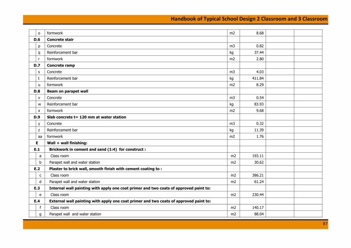
Handbook of Typical School Design 2 Classroom and 3 Classroom
87
o formwork m2 8.68
D.6 Concrete stair
p Concrete m3 0.82
q Reinforcement bar kg 37.44
r formwork m2 2.80
D.7 Concrete ramp
s Concrete m3 4.03
t Reinforcement bar kg 411.84
u formwork m2 8.29
D.8 Beam on parapet wall
v Concrete m3 0.54
w Reinforcement bar kg 83.93
x formwork m2 9.68
D.9 Slab concrete t= 120 mm at water station
y Concrete m3 0.32
z Reinforcement bar kg 11.39
aa formwork m2 1.76
E Wall + wall finishing:
E.1 Brickwork in cement and sand (1:4) for construct :
a Class room m2 193.11
b Parapet wall and water station m2 30.62
E.2 Plaster to brick wall, smooth finish with cement coating to :
c Class room m2 386.21
d Parapet wall and water station m2 61.24
E.3 Internal wall painting with apply one coat primer and two coats of approved paint to:
e Class room m2 230.44
E.4 External wall painting with apply one coat primer and two coats of approved paint to:
f Class room m2 140.17
g Parapet wall and water station m2 88.04

Handbook of Typical School Design 2 Classroom and 3 Classroom
88
F Floor finishing
Non slippery Ceramic tiles 300 mm x 300 mm, bedded and jointed in cement mortar, pointed in coloured cement as specified, including all necessary fixing accessories, laid as pattern ; all as described to the following:
a Class room m2 168.00
b Verandah, stair and ramp m2 71.55
c finishing patterns to form ramp surface m2 26.88
G Door frames, window frames and jalousie
a door (5/7) m3 0.16
b window (5/7) m3 0.53
c jalousie (5/7) m3 0.37
d Jalousie grid (1/7) m3 0.17
H Door, windows and concrete rooster
a Front doors, as specified in architectural drawings unit 3.00
b windows glass (650x800 mm), included the frames and hinges if needed, refer to drawings unit 36.00
c window glass (270x710 mm), included the frames and hinges if needed, refer to drawings unit 72.00
d window glass (310x430 mm), included the frames and hinges if needed, refer to drawings unit 12.00
e window glass (200x850 mm), included the frames and hinges if needed, refer to drawings unit 6.00
f concrete rooster unit 30.00
g back doors, as specified in architectural drawings unit 3.00
I Roofing works and Ceilings
I.1 Roof Trusses
a main chord (8/12) m3 2.11
b stiffener (6/12) m3 0.37
c purlin (6/12) m3 0.81
d kasau (timber element) (5/7) m3 1.90
e timber bracing (6/12) m3 0.35
f cleat (5/7) m3 0.02
I.2 Roof Cover
g Galvanized iron sheet roof & screw m2 533.00

Handbook of Typical School Design 2 Classroom and 3 Classroom
89
h fascia board (2/25) m' 51.32
i Board painted triplex m2 206.40
I.3 Ceilings
j hanger (6/12) m3 2.25
k plafond (5/7) m3 0.98
l ceilings boards (9mm thick) m2 163.40
m cornice m' 88.20
J Railing works
Black steel pipe of balustrade 1 " and hand rails 2" with welded and bolted connection:
a Ramp m' 29.60
K Water station area works
a Water foucet T 23 B13V7N unit 4.00
b Floor trap TX 1 AVI unit 2.00
c PVC pipe 2 1/2" for grey water m' 3.30
d Ceramic at Water station area m2 6.25
Note: 1. Assumption depth of foundation = 1m
2. Assumption existing ground level =-0.55 m (refer to drawings)
3. Mechanical and electrical appliances are not included

Handbook of Typical School Design 2 Classroom and 3 Classroom
90
5. TECHNICAL SPECIFICATION
SECTION A - EARTHWORKS
A.1 GENERAL
A.1.1 Types of earthworks
The earthwork consists of filling and excavation work, as shown on the
drawing.
A.1.2 Site clearing
The constructor shall execute the site clearing before commencing the filling
works, the area shall be cleaned from grass, trees, debris, wood, or other
organic waste, etc.
A.1.3 Material for filling
Material to be used is excavated soil and shall be cleaned from grass, trees,
debris, wood, or other organic waste, etc and shall be mechanically
compacted.
A.2 CONFORMITY WITH DRAWINGS
Earthworks shall be finished to conform within the following limits to the
levels, lines, and cross sections specified or shown on the drawings or
directed by the Engineer.
A.2.1 Dimensions measured of earth work/filling work are the widths, length
and level measured from specified edge shown in drawings. The top
level shall not deviate by more than 10 mm from levels shown on the
drawings. The top level of the foundation measured must be taken to
100 year flood level as shown on the drawings.
A.2.2 Before filling the excavation for foundation with approved material, the
pit shall be cleared from retaining water, debris.
A.3 EXCAVATION
A.3.1 Common excavation
Common excavation shall refer to excavation in materials, in which the
material to be excavated is common soil
A.3.2 Suitable material
Suitable material shall comprise all that are acceptable in accordance with the
requirements of the material of filling work
A.2.3 Unsuitable material
Unsuitable material shall comprise:
(a) Materials from swamps, marshes or bogs, running silt peat, logs,
perishable material, slurry or mud; mining slime; or
(b) Any materials which are of construction and demolition debris

Handbook of Typical School Design 2 Classroom and 3 Classroom
91
SECTION B – RUBBLE FOUNDATION
B.1 The composition of mortar for bedding and connecting in rubble
foundation is of 1:4 of cement and sand.
B.2 Before installing the dimension and elevation of the pit, it shall be
cleaned from standing water, debris, and all unnecessary things.
B.3 Maximum diameter of rubble used for the foundations shall be not
more than 30 cm, and the rubble shall be free from dust, mud, or
other soil and it must have a rough surface.
B.4 The depth of the foundation must reach the hard soil or minimum of
80 cm. The width of the foundation must be at least 80 cm
B.5 The arrangement of the rubbles in the foundation must not follow a
straight line for good connectivity.
B.6 Local foundations/footings must be provided if the level of hard soil is
too deep.
SECTION C - WALL
C.1 BRICK BLOCK
C.1.1 The brick shall be clay brick. All bricks shall have uniform dimension
of 5 x 10 x 20 cm. It should be completely burnt and flat. It should
not break easily and the corners should not have damage.
C.1.2 All bricks should be soaked in water, prior to laying.
C.2 MORTAR
Mortar mix for wall construction should be in composition of 1 : 4 (cement :
sand) with appropriate amount of water. Maximum thickness of the mortar
used in wall construction is 15 mm, and the minimum is 8 mm.
C.3 WALLS
The arrangement of the brick must overlap each other and neat. Anchorage
should be installed as in the drawings
SECTION D – REINFORCED CONCRETE WORKS
D.1 CEMENT
The cement used in the concrete works must be portland cement. It should
not harden. It should be dry and have uniform color. It should be free from
other materials.
D.2 AGGREGATES
D.2.1 Fine aggregate should be clean from mud and organic materials. It
should be taken from rivers/ quarries

Handbook of Typical School Design 2 Classroom and 3 Classroom
92
D.2.2 Coarse aggregates should be free from mud and organic materials. It
should be taken from rivers/quarries and the size should be
approximately 1- 2 cm.
D.3 WATER
The water used in the concrete works should comply on these conditions:
- It should be clean
- It should be clear and have no odor
- It should be free from oil, acid, salt, organic material, etc, that can affect
reinforcement bars
D.4 STEEL REINFORCEMENT
D.4.1 General
Steel Reinforcement used is steel bar of type U-32 for deformed bar BJTD-32
(fy= 3200kg/cm2) and type U-24 for undeformed bar BJTP-24 (fy= 2400 kg/
cm2). For steel bar with diameter > 10 mm, deformed bar BJTD-32 should be
used. For steel bar with diameter < 10 mm undeformed bar BJTP-24 may be
used.
D.4.2 Condition
The reinforcement bar used should have uniform size and straight. It should
be clean and have no rust. The diameter used must follow with the required
diameter presented in the drawings.
D.4.3 Binding Wire
The binding wire for steel reinforcement shall be of 16 SWG soft pliable
annealed steel wires.
D.5 MIX DESIGN
The concrete used in the construction works must have a minimum concrete
strength of 17.5 MPa (1 cement: 2 sand: 3 gravel). All mix design standards
must comply with SNI 03-1726-2002 “Guideline on Reinforced Concrete
Design for Building- Tata Cara Perencanaan Struktur Beton Untuk Bangunan
Gedung”
D.6 MIXING OF CONCRETE
• The mixing plant shall be operated at clear space and the machine
has to stand on a stable position, safe, and has good accessibility.
The concrete shall be mixed up to a uniform color and consistency.
• Mixers, which have been out of use for more than 30 minutes, shall
be thoroughly cleaned before any fresh concrete is mixed.
• The mixer shall be kept on clean condition by washing the mixer
immediately after finishing the work.
• Hand mixing of concrete should not be allowed normally, but if the
quantity of concrete is small, and at the absolute discretion of the
engineer, hand mixing may be permitted.
• Hand mixing of concrete shall be carried out on a hard, even and
impervious surface of adequate size.

Handbook of Typical School Design 2 Classroom and 3 Classroom
93
• In mixing the concrete the gravel and sand should be properly mixed
first, then cement can be poured subsequently. Last, provide a
depression in the center, add an appropriate amount of water and
mix all materials.
D.7 TESTING MIXING
In testing the mixing consistency, place the concrete on the hand and check
for the shape. If the concrete tends to spill or run over, it means that there is
too much water in the mixture.
D.8 TRANSPORTING AND PLACING
D.8.1 Transporting
The concrete shall be discharged from the mixer and transported to the
concrete pouring position. The concrete transported or otherwise exposed
during wet weather shall be covered to prevent washing out by rain, or an
undue increase in water content in severe cases.
D.8.2 Placing
The concrete shall be placed in positions with the sequence as indicated on
the drawings, in the specifications, or as directed by the engineer. It shall be
deposited as close as possible to its final position.. It shall be placed in such
manner to avoid segregation of the concrete or displacement of the
reinforcement and other embedded items or formwork. Fresh concrete shall
not be placed against in situ concrete, which has been in position for more
than 3 minutes, unless a construction joint has been formed. Club hammer
and steel rod can be used for compaction.
D.9 JOINT CONSTRUCTION
D.9.1 Position
Concreting shall be carried out continuously up to construction joint. The
position and arrangement of the joints shall be as indicated on the drawings.
D.9.2 Preparation of joint
When work has to resume on a surface which has hardened, the whole
surface shall be thoroughly chipped, all laitance removed, swept clean, wetted
and covered with a layer of a minimum thickness of 3 mm of mortar
composed of cement and sand with the same ratio as in the concrete mixture.
The mortar shall be freshly mixed and placed immediately before the placing
of the concrete. The procedure shall be as such to avoid the formation of
bands. The prepared joint surfaces shall be inspected and approved by the
engineer before commencement of concreting.
D.10 CURING AND PROTECTION
Concrete shall be protected during the first stage of hardening from the
harmful effects of sunshine, drying winds, rain or running water. The
protection shall be applied as soon as practicable after completion of placing
using one or more of the following methods:

Handbook of Typical School Design 2 Classroom and 3 Classroom
94
(a) The concrete shall be covered with a wet layer of sacking or similar
absorbent material for approximately 7 days.
(b) Before and after the formwork is removed, spray the concrete routinely.
D.11 FORMWORK
Plywood may be used as the material for formwork. Prior to concreting, the
formwork shall be cleaned from adhering concrete and the bottom part
should be free from debris.
Additional support to formwork may be needed to maintain the shape of
formwork and to retain compressive forces generated in concrete placement.
D.12 DEFECTIVE CONCRETE FINISHES
D.12.1 General
Any concrete found to have a defective finish shall be reformed by skilled
workers using methods approved by the engineer.
D.12.2 Prompt remedial measures
Unless approved by the engineer, the repair of imperfection in the formed
concrete shall be carried out immediately after the removal of formwork.
D.12.3 Damage and defect of concrete
Concrete that is damaged by any cause, concrete that shows honey-comb,
cracks or other defects, and concrete which has excessive surface depressions
beyond accepted tolerances must be cut out and built up to bring the surface
to the prescribed lines. Minor bulges and abrupt irregularities beyond the
specified limits shall be reduced by grinding to the approved tolerances. All
materials, procedures, and operations used in the repair of concrete shall be
subjected to the approval of the engineer.
D.12.4 Fittings
All fittings shall be bonded tightly to the surface of the structure and be free
from shrinkage cracks. Repair of concrete shall be carried out by one or more
of the following methods:
(a) Concrete replacement
(b) Hand placed cement mortar
(c) Pneumatically placed cement mortar
(d) Dry pack
(e) Epoxy mortar
The type and methods of repair to be used in any particular case shall be
subjected to the approval of the engineer.
D.13 STRIKING AND REMOVAL OF FORMWORK
All forms shall be removed without damaging the concrete. Before removing
the forms, the concrete shall be exposed by removing of the side forms or
otherwise as required by the engineer in order to ensure that it has
sufficiently hardened.

Handbook of Typical School Design 2 Classroom and 3 Classroom
95
D.14 CONDITION, BENDING, FIXING OF REINFORCEMENT BARS
D.14.1 Condition
The reinforcement bars shall be free from rust, oil or other coating, which is
liable to weaken the bonding between the concrete and steel, before being
placed in the forms. Any bars that are pitted with rust shall be rejected.
D.14.2 Bending
The bending dimensions and tolerances and the dimensions of end
anchorage, seismic hooks, stirrups, and development lengths shall be in
accordance with SNI 03-1726-2002. All steel reinforcements shall be
fabricated to the forms and dimensions as shown by the drawings. It also
should be placed appropriately as shown in the drawings.
D.14.3 Fixing
The reinforcement shall be fixed in the formwork and held firm against
displacement by approved cover blocks and binding wires to ensure that the
meshwork or reinforcing bars will retain their designed form and exact
positions in the formwork during the process of placing and compacting
concrete. Bars intended to be in contact when passing each other shall be
securely held together at intersections with binding wires.
No concrete shall be placed until all formwork, installation of reinforcing bars
and preparation of surfaces involved in the placing have been completely
prepared by the constructor and the completion has been inspected and
approved by the engineer.
D.14.5 Laps, seismic hooks and length of development
Lap lengths of the reinforcing bars shall be calculated on the permissible
stresses for the full tensile stresses in the bars. Laps in the reinforcement
shall be suitably staggered. The length of lapped joints shall normally be not
less than 40 times the bar diameter or minimal 60 cm.
Seismic hooks must be provided in every stirrups provided in the beam and
column. Minimum 40 d length development must be provided in the
connection of beam and column (refer to drawings).
SECTION E – PLASTER WORKS
E.1 GENERAL
E.1.1 Mortar used for plaster works is the mixture of portland cement and
sand with addition of sufficient water in it. The materials for plaster
mortars must be accurately gauged.
E.1.2 All plaster work should be conducted by skilled workers to get proper
result.
E.2 EXECUTION OF WORKS
E.2.1 The wall shall be watered and cleaned before plastering and it should
be applied to all surface of wall (exposed or unexposed)

Handbook of Typical School Design 2 Classroom and 3 Classroom
96
E.2.2 Exposed concrete and foundation surfaces shall be plastered for
finishing. The surface shall be scraped or chipped before plastering.
E.2.3 Composition of mixed mortar and the place to be plastered work is 1
cement and 4 sand.
E.2.4 The surface of the wall should be smoothened after plastering works
using cement and water mixture.
SECTION F – WOODEN WORK
F.1 CODES / STANDARDS
Unless mentioned in further requirements, the constructor must follow:
• Indonesian Material Standard (PUBI - 1982)
• Peraturan Konstruksi Kayu Indonesia
F.2 WOODEN MATERIAL
The constructor shall provide the materials in dry condition (small water
content), straight, smooth, has no defect, etc.
F.2.1. Material used for list-plank and wooden ventilation is of good quality
of wood, straight, with no defect, and no crack.
F.2.2. Material used for roof frame/truss structures shall be from strong
wood, or of second class or first class based on codes.
F.2.3. Conformity to structural drawings, locations, dimensions and
structural sufficiency during handling/erection must be considered in
construction.
F.3 WOODEN CONSTRUCTION
F.3.1. Use minimum Φ 10 mm bolts and 4.40 iron sheet/ 20.100 mm plank
to connect the main chord in roof trussing system.
F.3.2. Nail only can be used for connecting wooden elements in the case
where the elements are not main chord of roof truss elements or the
elements are not structural elements (windows, doors, etc).
F.3.3. Detailing should be provided as presented in the drawings.
SECTION G – ROOFING AND CEILING WORKS
G.1 ROOF COVERING
G.1.1 Use light weight and easy to install materials for roof covering, such
as galvanized iron sheet
G.1.2 Provide screw and washer to connect the roof materials to the purlin.
G.1.3 Provide cleat to support and maintain the position of purlin
G.1.4 Provide fascia 2/25 cm (list-plank) at the end of the roof trusses

Handbook of Typical School Design 2 Classroom and 3 Classroom
97
G.2 CEILING ROOF WORKS
G.2.1 Material Requirement
• Gypsum boards for the ceiling shall be of the best quality and moisture
resistant.
• Minimum thickness of gypsum board used is 9 mm.
• The board should be unwrapped and sufficiently hard.
• The smooth surface shall be free from defects.
G.2.2 Installation
• Before installing the ceiling, the engineer shall inspect the framework
which must be suitable to the leveling, patterns, and dimensions shown
on the drawings.
• The cutting of the gypsum (in accordance with the dimensions) to the
exact length shall be in a perfect finish condition.
• The gypsum sheets shall be screwed carefully to the framework.

Handbook of Typical School Design 2 Classroom and 3 Classroom
98
6. CLOSURE
This guideline is developed to provide an alternative design for the person in charge in school committee and to assist the school community in constructing an
earthquake resistant school building. The guideline may be used without engineering consultancy, but it is recommended that the school committee/teachers
consult an engineer regarding the design parameters and construction methods, to obtain a proper result.
Several design factors that must be noted by the person in charge are:
1) The level of the hard soil is not specified in the drawings. It means that depth of foundation must suitable with the local condition for hard soil level.
2) The 100 year flood level is not specified in the drawings. It means that the level of the rubble foundation must suitable with the local 100 year flood level.
3) No local footing is presented in the drawings for the typical design. However, a detailing of local footings is provided in the case where the local hard soil depth
is beyond the depth of an ordinary rubble foundation.
4) The BOQ presented in this guideline is calculated using some assumptions, as noted in the BOQ section.
5) All changes in the design must be consulted to an engineer/building consultant in the area.

REFERENCES
Pribadi, Krishna S.; Kusumastuti, Dyah; Handayani, Nurita; Edwin. Panduan Konstruksi dan Perkuatan Bangunan Sekolah Tahan Gempa. CDM-ITB. 2008
Boen, Teddy & Associates. Constructing Seismic Resistant Masonry Houses. United Nation Center for Regional Development (UNCRD). 2009
Kusumastuti, Dyah & Handayani, Nurita. Pedoman Mitigasi Fisik untuk Sekolah Melindungi Siswa Dari Bencana Gempabumi. CDM-ITB Supported by AUS-AID. 2008
http://www.gawler.sa.gov.au/webdata/resources/images/Shading.jpg
Badan Standardisasi Nasional, “SNI 03-1726-2002-Tata Cara Perhitungan Struktur Beton Untuk Bangunan Gedung”.
Badan Standar Nasional Pendidikan. Standar Sarana dan Prasarana Sekolah/Madrasah Pendidikan Umum. 2006 (Downloaded from:
http://74.125.153.132/search?q=cache:qZz7OHDkZkQJ:118.98.212.211/explorer/view.php%3Ffile%3DInstrumen%2BAkreditasi%2BSekolah%2BMadrasah/REFERE
NSI‐PERATURAN‐PERUU‐AN/Standar%2BSarana%2BPrasarana‐BSNP%2B160107.doc+pedoman+standar+prasarana+gedung+sekolah+BSNP&cd=1&hl=en&ct=clnk)
