handbuch manual manuel masi65 m12 - murrelektronik · concerning this manual : the text,...
TRANSCRIPT
Handbuch
Manual
Manuel
MASI65 M12

Concerning this manual : The text, illustrations, diagrams and examples used in this manual serve solely for the purpose of expla-nation, operation and application of Input/Output modules of the MASI65-M12 series. If you should have any further reaching questions regarding the installation and set-up of the equipment described in this manual, please don't hesitate to contact us. We would be glad to assist you any time. Murrelektronik reserves the right to make technical changes or modifications to the devices and to this manual without prior notice.
Chapter overview : The "Safety Information" section must be read without fail prior to working with the products and the sys-tem. This section contains information required for safe installation and handling. The "Configuration Information" section directs itself to system planners. It offers important information and details relevant to successful configuration. The "Installation" section provides details regarding installation, in both mechanical and electrical context. This chapter addresses itself in particular to qualified and trained electricians responsible for the assem-bly and installation of system components. The "Setup" and "Diagnosis" sections are intended for the setup personnel. They offer important notes and information with regard to the rapid and uncomplicated setup of modular modules and of the whole system.
Murrelektronik GmbH Postfach 1165 71567 Oppenweiler Telefon ++49(0)7191/47-0 Falkenstraße 3 71570 Oppenweiler Telefax ++49(0)7191/47-130 Internet : http://www.murrelektronik.com
MASI65-M12 Series User's Manual
Art.-No. Description 55570 MASI65 DI8/0,4A Y 8xM12 55571 MASI65 DI4/0,2A DO4/2A Y 8xM12 55572 MASI65 DI8/0,4A BV Y 8xM12 55573 MASI65 DI4/0,2A BV Y 4xM12 55574 MASI65 DO4/0,5A Y 4xM12 55610 MASI65 DI4/0,2A 4xM12 55612 MASI65 DI8/0,4A 8xM12 55614 MASI65 DO4/0,5A 4xM12 55615 MASI65 DO4/2A 4xM12 55616 MASI65 DO8/0,5A 8xM12 55618 MASI65 DI4/0,2A DO4/0,5A 8xM12 55619 MASI65 DI4/1,6A DO4/2A 8xM12 55622 MASI65 DI4/0,2A BV 4xM12 55623 MASI65 DI8/0,4A BV 8xM12 55624 MASI65 DI4/0,2A DO4/2A 8xM12 55625 MASI65 DI2/0,2A DO2/2A 4xM12 55628 MASI65 DI4/0,2A DO4/0,5A Y 8xM12 55629 MASI65 DI4/0,2A Y 4xM12 55675 MASI65 DI4/0,15A DO3/2A AB Y 7xM12 55676 MASI65 DI8/0,2A AB Y 8xM12 55677 MASI65 DI4/1,6A DO3/2A AB Y 7xM12
User's manual : Art. No. 55 645 Version 1.1

MASI65-M12 User's Manual
V 1.1 3
Table of contents 1 SAFETY INFORMATION ...................................................................................................................... 8
1.1 DESIGNATED USE.............................................................................................................................. 8 1.2 TARGET GROUPS .............................................................................................................................. 8 1.3 REGULATIONS .................................................................................................................................. 9
1.3.1 EU directives ........................................................................................................................... 9 1.3.2 Electrical safety ....................................................................................................................... 9 1.3.3 General information................................................................................................................. 9
1.4 INFORMATION REGARDING STANDARDS ............................................................................................ 10 1.4.1 Equipment standards ............................................................................................................ 10 1.4.2 EMC Standards ..................................................................................................................... 10 1.4.3 Safety standards ................................................................................................................... 10
1.5 EXPLANATION OF SYMBOLS ............................................................................................................. 11 1.6 USE OF ATTENTION SIGNS ............................................................................................................... 11
1.6.1 Use of danger signs .............................................................................................................. 11 1.6.2 Use of numbering in illustrations ........................................................................................... 11 1.6.3 Use of handling instructions .................................................................................................. 11 1.6.4 Use of foot notes ................................................................................................................... 11
2 CONFIGURATION INFORMATION.................................................................................................... 12 2.1 SYSTEM DESCRIPTION..................................................................................................................... 12 2.2 SYSTEM DATA................................................................................................................................. 14 2.3 INFORMATION FOR THE BEGINNER.................................................................................................... 15 2.4 ELECTRICAL SPECIFICATION ............................................................................................................ 16
2.4.1 System cables ....................................................................................................................... 16 2.4.2 System power supply ............................................................................................................ 18 2.4.3 Voltage drop.......................................................................................................................... 19 2.4.4 Cable cross-sections............................................................................................................. 20
2.5 SLAVE PROFILE............................................................................................................................... 21 2.6 ADRESSING .................................................................................................................................... 21 2.7 SYSTEM CONFIGURATION ................................................................................................................ 23
2.7.1 Configuration with an AS-Interface addressing device ......................................................... 23 2.7.2 Configuration via the AS-Interface master ............................................................................ 24
2.8 AUTOMATIC CONFIGURATION ........................................................................................................... 25 2.9 CASCADING SLAVES ........................................................................................................................ 25 2.10 AB SLAVES ................................................................................................................................ 25
3 INSTALLATION INFORMATION........................................................................................................ 26 3.1 MOUNTING ..................................................................................................................................... 26
3.1.1 Screwed mounting ................................................................................................................ 26 3.1.2 Screwed mounting of an 8-way module................................................................................ 26 3.1.3 Screwed mounting of a 4-way module.................................................................................. 27 3.1.4 DIN-rail mounting .................................................................................................................. 27
3.2 WIRING .......................................................................................................................................... 28 3.2.1 Field bus................................................................................................................................ 28 3.2.2 Power supply......................................................................................................................... 28 3.2.3 Functional Earth (FE) connection.......................................................................................... 29
4 MODULE CONNECTION TECHNIQUE.............................................................................................. 30 4.1 FIELD BUS CONNECTION .................................................................................................................. 30
4.1.1 Cable layout .......................................................................................................................... 30 4.1.2 Bus cable connection ............................................................................................................ 30 4.1.3 Bus branching function.......................................................................................................... 32
MASI65-M12 User's manual
4 V 1.1
4.2 POWER SUPPLY CONNECTION ..........................................................................................................33 4.2.1 Cable layout...........................................................................................................................33 4.2.2 Auxiliary supply connection ...................................................................................................33
4.3 SENSOR AND TRANSMITTER CONNECTION.........................................................................................35 4.3.1 Pin arrangement of the round plug connector M12 with single signal assignment ...............36 4.3.2 Pin arrangement of the round plug connector M12 with double signal assignment..............36
4.4 ACTUATOR CONNECTION (LOADS) ....................................................................................................37 4.4.1 Pin arrangement of the round plug connector M12 with single signal assignment ...............37 4.4.2 Pin arrangement of the round plug connector M12 with double signal assignment..............37
4.5 ADDRESSING DEVICE CONNECTION...................................................................................................38 4.5.1 Addressing interface for MASI65-M12 modules....................................................................38
5 DIAGNOSIS DISPLAYS......................................................................................................................39 5.1 BUS / DEVICE STATUS DISPLAYS ......................................................................................................40 5.2 I/O STATUS DISPLAY........................................................................................................................40 5.3 AUXILIARY SUPPLY ..........................................................................................................................40
6 SHORT-CIRCUIT/OVERLOAD RESPONSE ......................................................................................41 6.1 SENSOR / TRANSMITTER SUPPLY......................................................................................................41
6.1.1 MASI65-M12 standard slaves with SAP4.0...........................................................................41 6.1.2 MASI65-M12 standard and AB slaves with SAP4.1..............................................................41
6.2 OUTPUTS........................................................................................................................................41 6.2.1 MASI65-M12 standard slaves with SAP4.0...........................................................................41 6.2.2 MASI65-M12 standard and AB slaves with SAP4.1..............................................................41
7 DATA SHEETS FOR THE MASI65-M12 SERIES ..............................................................................42 7.1 INTERFERENCE IMMUNITY DATA........................................................................................................42 7.2 MASI65-M12 PRODUCT-SPECIFIC DATA STANDARD SLAVES .............................................................43
7.2.1 MASI65 DI8/0,4A Y 8xM12 Art. No. : 55570 ........................................................................43 7.2.2 MASI65-M12 DI4/0,2A DO4/2A Y 8xM12 Art. No : 55 571 ..................................................44 7.2.3 MASI65 DI8/0,4A BV Y 8xM12 Art. No : 55572 ...................................................................45 7.2.4 MASI65 DI4/0,2A BV Y 4xM12 Art. No : 55573 ..................................................................46 7.2.5 MASI65 DI4/0,2A 4xM12 Art. No : 55610............................................................................47 7.2.6 MASI65 DI8/0,4A 8xM12 Art. No : 55612............................................................................48 7.2.7 MASI65 DO4/0,5A 4xM12 Art. No : 55614...........................................................................49 7.2.8 MASI65 DO4/2A 4xM12 Art. No : 55615..............................................................................50 7.2.9 MASI65 DO8/0,5A 8xM12 Art. No : 55616..........................................................................51 7.2.10 MASI65 DI4/0,2A DO4/0,5A 8xM12 Art. No : 55618............................................................52 7.2.11 MASI65 DI4/1,6A DO4/2A 8xM12 Art. No : 55619..............................................................53 7.2.12 MASI65 DI4/0,2A BV 4xM12 Art. No : 55622......................................................................54 7.2.13 MASI65 DI8/0,4A 8xM12 Art. No : 55623............................................................................55 7.2.14 MASI65 DI4/0,2A DO4/2A 8xM12 Art. No : 55624..............................................................56 7.2.15 MASI65 DI2/0,2A DO2/2A 4xM12 Art. No : 55625..............................................................57 7.2.16 MASI65 DI4/0,2A DO4/0,5A Y 8xM12 Art. No : 55628 .......................................................58 7.2.17 MASI65 DI4/0,2A Y 4xM12 Art. No : 55629 ........................................................................59
7.3 MVK12 AB PRODUCT-SPECIFIC TECHNICAL DATA AB SLAVES...........................................................60 7.3.1 MASI65 DI4/0,2A DO3/2A AB Y 8xM12 Art. No : 55 675 ....................................................60 7.3.2 MASI65 DI8/0,2A AB Y 8xM12 Art. No : 55676 ...................................................................60 7.3.3 MASI65 DI4/1,6A DO3/2A AB Y 8xM12 Art. No : 55677 ....................................................62
8 MODULES VERSIONS AND FEATURES ..........................................................................................63 8.1 MASI65-M12 : 8-WAY MODULE ......................................................................................................63 8.2 MASI65-M12 : 4-WAY MODULE .......................................................................................................64
9 LIST OF ILLUSTRATIONS .................................................................................................................65
10 LIST OF TABLES ............................................................................................................................66

MASI65-M12 User's Manual
V 1.1 5
MASI65-M12 User's manual
6 V 1.1
Manual additions / Corrections
Vers. Section Additions / Corrections Date / Name 1.0 Issued D. Kaulisch / M.H. 1.1 MVK12-ASI => MASI65-M12 27.07.04 ERW
Notes :

MASI65-M12 User's Manual
V 1.1 7

MASI65-M12 User's manual
8 V 1.1
1 Safety information 1.1 Designated use The input and output modules of the MASI65-M12 series are designated for use only in those areas as described in this manual. Strict adherence to the data specified in this manual must be ensured. The products avec been devel-oped, manufactured, tested and documented in compliance with current safety codes. The equipment poses no danger to operating personnel or material if configuration, assembly and opera-tion are performed in compliance with the stated handling and safety regulations. Unqualified intervention in the hardware and software of our equipment, disregard of warning labels found on the equipment or non-observance of the information in this product manual can result in injury or seri-ous damage to man and/or material. Only supplementary or extension devices that have been recommended by Murrelektronik may be em-ployed in conjuction with products of the MASI65-M12 series. Any application or usage beyond and above this shall be regarded as non-designated. 1.2 Target groups This manual addresses itself exclusively to qualified and trained electricians knowledgeable in the safety standards of automation technology. Only a qualified, trained electrical tradesman knowledgeable in the safety standards of automation tech-nology may perform configuration, installation, set-up, maintenance and testing of the equipment. Only Murrelektronik technical personnel are allowed to undertake intervention in the hardware and soft-ware of our equipment, insomuch as this is not described in this manual.

MASI65-M12 User's Manual
V 1.1 9
1.3 Regulations Current safety and accident prevention laws valid for a specific application must be observed in the con-figuration, installation, setup, maintenance and testing of the equipment. 1.3.1 EU directives
This equipment fulfills the requirements of EC directive 89/336/EEC „Electromagnetic compatibility".
There are no restrictions to applications in residential, business and industrial areas, including industrial facilities large and small. 1.3.2 Electrical safety All devices connected to this equipment must fulfill PELV directives (Protected Extra Low Voltage) according to HD 384.4.41. 1.3.3 General information a) The designated function of this equipment is guaranteed only if the conditions for installation, sys-
tem extension, operation and maintenance are complied with. b) Only system extensions and cables are allowed with meet the requirements and regulations for
safety, electromagnetic compatibility and, where applicable, telecommunications transmission equipment and specifications. The installation of other extensions may violate these requirements and regulations or damage the equipment. Information concerning the type of system expansions and cables that are permitted, can be ob-tained either from your Murrelektronik distributor or taken from this manual.
c) The designated operation of the equipment is guaranteed only with the housing fully installed. d) This product is designed and manufactured to assure protection against damage if designated
usage and proper maintenance are observed.

MASI65-M12 User's manual
10 V 1.1
1.4 Information regarding standards 1.4.1 Equipment standards - EN 50295 Low voltage switching devices – Control systems and device interfaces – Actuator
Sensor Interface (AS-I). - EN 60 947-1 Low voltage switching devices Part 1 : General conventions. 1.4.2 EMC Standards - EN 50295 Low voltage switching devices – Control systems and device interfaces – Actuator
Sensor Interface (AS-I). - EN 55011 Industrial, Scientific and Medical high frequency equipment - Radio interference - Limit
values and sensing methods. - EN 61000-4-2 EMC Part 4 : Testing and sensing methods Main section 2 : - Test of immunity to static electrical discharge according to basic EMC standards. - EN 61000-4-3 EMC Part 4 : Testing and sensing methods Main section 3 : - Test of immunity to RF electromagnetic fields. - EN 61000-4-4 EMC Part 4 : Testing and sensing methods Main section 4 : - Test of immunity to rapid transient disturbances/burst - EMC basic standards. - EN 61000-4-6 EMC Part 4 : Testing and sensing methods Main section 6 : - Test of immunity to asymmetric RF input - EMC basic standard. - AS-i Complete Specification Version 2.1, Section 8 EMC. 1.4.3 Safety standards - EN 60 295 Low voltage switching devices – Control systems and device interfaces – Actuator
Sensor Interface (AS-I). - EN 60 947-1 Low voltage switching devices Part 1 : General conventions. - EN 60 529 Type of housing protection (IP-Code). - VDE 0100 Part 410/HD 384.4.41 Installation of power systems and equipment with nominal voltages
up to 1 000V Part 4 : Protective measures. - Chapter 41 : Protection against electrocution.

MASI65-M12 User's Manual
V 1.1 11
1.5 Explanation of symbols 1.6 Use of attention signs Notes containing important information are specially marked. These are illustrated as follows :
Attention text ........
1.6.1 Use of danger signs Danger signs are additionally marked with an enclosing frame. CAUTION : Disregard of safety measures may result in damage to equipment and other serious consequences. DANGER : Non-compliance with the relevant safety measures poses a danger to the health and life of the user. 1.6.2 Use of numbering in illustrations Illustrations are numbered with white numbers in black, round fields. Example : � Text 1...... � Text 2...... � Text 3...... The explanatory text follows in tabular form under the same number, in direct context to the preceding illustration. 1.6.3 Use of handling instructions Handling instructions describe the sequence of steps during installation, setup, operation and mainte-nance that must be strictly observed. The numbering (black numerals in round white fields) is given in a sequential and ascending order. Example : � Instruction 1........ � Instruction 2........ � Instruction 3........ 1.6.4 Use of foot notes Supplementary information is marked with superscripted numerals (example. : Text Text 1) Text Text). These are explained in the form of footnotes beneath tables or text at the end of the page.

MASI65-M12 User's manual
12 V 1.1
2 Configuration information
2.1 System description The AS-Interface is a simple and cost-saving wiring system based on a 2-wire cable for data and power transmission to sensors over a distance of up to 100 m. System expansion > 100 m is possible with the use of repeaters. The application area concentrates mainly on lower level industrial automation for networking simple and mostly binary sensors and actuators. The AS-Interface is a substitute for traditional wiring between sensors, actuators and the PLC. System-based mechanisms effectively support setup, operation and maintenance. Every AS-Interface system requires a control unit, the master. This is available as a PLC specific module, a PC card or a gateway. The application program on the control system or PC controls the decentralized I/O groups (slaves) via the master. The master performs cyclical information exchange between the mas-ter and the slaves independently. According to standard specifications, an AS-Interface network supports the operation of maximum 31 slaves. According to extended specifications, it supports the operation of maximum 62 modules. There are two types of slaves : active and passive modules. Active modules are slaves with interfaces linking to common binary sensors and actuators. Each data transmission cycle between the master and the slave is limited to 4 input data bits and 4 output data bits. This kind of structure and the length of the data messages support the operation of up to 124 inputs and 124 outputs (standard specifications). The extended specification supports the operation of 248 inputs and 186 outputs. Passive modules are typically fitted with a standard electromechanical interface (for ex. round plug con-nector M12) for a direct connection of sensors and actuators to the AS-Interface integrated into the field bus cable. In order to ensure an accurate data transmission between the master and the slaves, each slave - A or B - must be assigned to a specific address configurable from 1 to 31. Addressing can either be performed by a manual addressing device or by the master itself. AS-Interface products are generally marked by specific logos. Such identifications allow to distinguish between certified products and such products that are AS-Interface certified by the manufacturer.
Fig. 2-1 : AS-Interface Fig. 2-2 : Marking

MASI65-M12 User's Manual
V 1.1 13
Owing to the signal shape for the data transmission, it is not necessary to provide terminating resistors. Thanks to the intelligent data protocol, AS-Interface systems are extremely non-sensitive to disturbance. Consequently, you can use a non-screened bus cable. The structure of AS-Interface systems can be compared to an ordinary electrical installation with different network topologies : line, star or tree structure.
Fig. 2-3 : Topology of the AS-Interface system
The data cycle time depends on the network topology and the entire scope of the system. For a complete system with 31 slaves it is about 5 ms and with 62 slaves (extended specifications) about 10 ms.
Master
PLC
Slave
Slave
Slave
Slave
Slave
Slave
Slave
Slave
Slave
Slave
Line structure
Master
PLC
Slave
Slave
Slave Slave
Slave
Slave
Slave
Slave
Slave
Slave Slave
Slave
Star structure
Master
PLC
Slave
Slave
Slave
SlaveSlave
Slave
Slave
Slave
Slave
Slave
Tree structure
MASI65-M12 User's manual
14 V 1.1
2.2 System data
Topology Tree structure
Transfer medium Two-wire cable (non-screened) for data and power (up to 8A)
Cable length Sum of all lines of derivation: max. 100 m
Number of slaves Max. 31 or max. 62
Number of binary ele-ments (according to the specification 2.0)
Up to 4 sensors and actuators per slave (max. 124, bidirectional max. 248 for a complete system)
Number of binary ele-ments (according to the specification 2.1)
Up to 4 sensors and 3 actuators per slave (max. 248 inputs and 186 outputs for a complete system)
Addresses A specific address for each slave between 1...31
or 1-31 A and 1-31 B (extended specification).
Addressing mode By means of a manual addressing device or via the master.
Messages Cyclic messages from the master to the individual slaves (master call) with instant reply from slave (slave reply).
Bit rate 4 bits of informative data per slave and message.
Data cycle time 5 ms with 31 slaves 10 ms with 62 slaves.
Error recognition Identification of faulty messages, automatic repeat.
Master functions - System initialization - Automatic slave detection - Non-cyclical parameter transmission - Bus and slave diagnosis - Error messages to control - Automatic addressing when a slave is replaced.
Table 2.2–1 : AS-Interface system data

MASI65-M12 User's Manual
V 1.1 15
2.3 Information for the beginner AS-Interface is a field bus system for industrial application whose advantages include no only its ease of handling in planning and application but also the good overview of the total system. To make the system even easier and safer for beginners to use, we recommend proceeding as outlined in the checklist below :
Work phase Questions Note Planning How many I/O's are re-
quired in total ? This determines whether one or more AS-Interface sys-tems will be needed for realization.
Planning How great is the system power requirement ?
Important for the selection of suitable system power supply units. Never switch AS-Interface power supply units in parallel !
Planning How large is the total scope of the system ?
Repeaters must be used if the sum of all cable lengths exceeds 100 m.
Configuration How are the modules to be assigned ?
To avoid addressing errors, create an assignment scheme and carefully label all addressed modules ac-cordingly !
Installation Where will the modules be installed ?
Depends on the module enclosure type : either in a switch cabinet or terminal box. Place modules of enclo-sure type IP 67 close to sensors and actuators for the sake of greater efficiency.
Setup How will the system con-figuration be executed ?
In configuration mode (master operating mode) the de-tected slave profiles are automatically read in by the master.
Setup Have all slaves been de-tected by the master ?
When all slaves have been detected, the master should be switched into protected operating mode. This enables exhaustive diagnostics.
Setup How can a simple I/O function test be performed ?
Quick and straightforward with special, easy to use setup tools 1 or via the gateway with graphics display. Alternatively with the PLC Software Tool.
1 e.g. : ASI Control Tools Article No 55714

MASI65-M12 User's manual
16 V 1.1
2.4 Electrical specification 2.4.1 System cables To meet individual application requirements, system wiring on the field bus side can be realized either with round cables2 or also with the yellow ribbon cable3 characteristic for AS-Interface systems. Cables are basically of the 2-wire type without PE cable. Cable screening in not necessary thanks to the transmission technology.
Two electrical aspects are decisive in the selection of a suitable transmission cable : a) DC resistance (line cross-section) for reasons of auxiliary power transfer b) Transmission characteristics Impedance from 80 to 120 ohms for 167 kHz
Additional auxiliary power is usually required for actuators. For an easy installation of ribbon cables, these are identified by different colours.
Cables yellow - AS-Interface field bus cable black - 24V DC auxiliary power red - 230V AC auxiliary power Cable leads brown - Field bus system cable (ASI+) 24V DC (+24V DC) auxiliary power AC auxiliary power blue - Field bus system cable (ASI-) 24V DC (0V) auxiliary power AC auxiliary power
AS-Interface products with direct connection for ribbon cable carry a geometric code. This offers reliable protection against electrical polarity reversal.
2 Art. No 55 747 3 Art. No. 55 743

MASI65-M12 User's Manual
V 1.1 17
Fig. 2-4 : AS-Interface cable
Fig. 2-5 : AS-Interface round cable according to DIN VDE 0281 Part 402
For standard profiled cables, the strand insulation is made of a rubber compound. For more critical appli-cations, particularly as regards chemical stability, TPE or PUR cables are available. The main area of application is the stationary wiring of machines and installations in a rough environment. For the transmission cable, you can also use a common 2-wire round cable without PE cable, particularly for chained applications or wiring in switch cabinets.
braun
2,04,0
blau
106°
3,6
6,5
10,0
9,0
Ø2,5

MASI65-M12 User's manual
18 V 1.1
2.4.2 System power supply
Fig. 2-6 : AS-Interface system power supply
AS-Interface systems require a 29,5V to 31,6V DC power supply conforming to IEC directives (PELV : Protected Extra Low Voltage).
Each AS-Interface branch requires its own power supply.
The data filter integrated into the power supply constitutes the basic difference in comparison with usual industrial power supplies. It enables the transmission of both power and data.

MASI65-M12 User's Manual
V 1.1 19
2.4.3 Voltage drop System-related limit values regarding system power supply must be strictly observed if maximum func-tional safety and fault-free operation are to be ensured. Always ensure that the system voltage, measured at the slave furthest away from the system power supply, does not drop below 26,5V DC. A voltage drop, dependent on the load current, results in the system cable as the sensors and actuators are supplied centrally from the AS-Interface power supply unit.
In critical cases, optimization can be achieved by changing the location of the system power supply unit within the system layout and by using power supply cables of a greater conductor cross-section (only for round cables).
AS-Interface modules with digital inputs support the direct connection of commercially available sensors. The voltage needed to operate the sensors is supplied by a slave internal power supply taken from the bus. With the lowest admissible supply voltage at slave level and with regard to voltage drops in the slave, optimal power supply of sensors is always guaranteed. The sensor power supplies of different AS-Interface modules supplied by the bus cable are not grounded and should in no case be coupled !

MASI65-M12 User's manual
20 V 1.1
2.4.4 Cable cross-sections The chief determining factor in selecting a suitable transmission cable in regard to energy transfer is the DC resistance. Initial conditions : � the cable length is 100 m � 31 slaves are connected to the cable at regular intervals, and � the current consumption of 65 mA is the same for all slaves (total current : 2 A) The table below shows the resulting drop of voltage between the power supply inputs and the connecting point of the last slave :
Cable cross-section in mm² 0,75 1,5 2,5 DC resistance in mOhm/m 52,0 26,6 16,0 Max. voltage drop in en V 5,4 2,7 1,6
Table 2.4–1 : Influence of various cross-sections

MASI65-M12 User's Manual
V 1.1 21
2.5 Slave profile Each slave is marked with a specific profile to assure unequivocal identification by the AS-Interface mas-ter. This profile is permanently programmed by the manufacturer and cannot be changed. The conditions for this are listed in the AS-Interface specifications. The profile consists of one data byte including the identification code (ID-Code) as well as the Inputs/Outputs code (I/O-Code). These data determine the slave function ("ID-Code") and the I/O configuration ("I/O Code"). The slave profile information (ID- and I/O-Code) is very important for an easy replacement of slaves in the system. It enables the master to check if the current configuration corresponds to the reference configura-tion.
2.6 Adressing
Fig. 2-7 : Manual addressing device
Each slave must be programmed with a unique address before setting up the AS-Interface system. To do so, you can use an addressing device4 or perform this configuration online via the master. Refer to the corresponding description.
Addresses are non-volatile : they remain stored even in case of power cutoff and can be changed a least 15 times per slave. Slaves conforming to the specification 2.1 are fitted with a chip including an EEPROM to store addresses. Addressing is not limited for such slaves.
4 Addressing device Art. No 55696

MASI65-M12 User's manual
22 V 1.1
According to the standard specifications, addresses can be assigned from 1 to 31. For systems conforming to the extended specifications (up to 62 slaves) the available address range is from 1A to 31A and 1B to 31B.
The installation of an appropriate master is required when using AS-Interface systems conforming to the extended specifications ! In a system you can generally operate simultaneously slaves conforming to standard specifications and slaves conforming to the specifications. Is this case, standard slaves are identified as slaves of type 'A' by the master. The same address that is not used in group 'B' is no more available.
New slaves that are not yet addressed are always allocated to the address 0. Although they have been recognized by the master, they are not included into the communication process. When replacing a slave while the system is operating (maintenance, repair, etc.) it is automatically allo-cated to the address 0 by the master (ÄChapter 2.8 Automatic configuration).

MASI65-M12 User's Manual
V 1.1 23
2.7 System configuration The system setup is established during the configuration phase ; the master must be used in configura-tion mode. In this mode, the master automatically recognizes the slaves connected to the bus. The fea-tures of the system, the "ID-Code" and "I/O-Code" as well as the slave addresses are stored by the mas-ter. In case of system extensions that are not in conformity with the AS-Interface specifications, it is possible that some slaves are not detected by the master.
As soon as the whole system is configured and the master is operating in "Protected mode" the differences in relation to the configured system can be automatically detected by the master (e.g. slave failures, damaged bus cable or system extensions). System configuration can be performed by an addressing device or directly via the master. The configura-tion procedures are different according to the selected mode. 2.7.1 Configuration with an AS-Interface addressing device � Address the slaves with the addressing device.
(For slaves with an addressing plug, this operation can be performed after step �). � Install the slaves and connect them to the system cable. � Switch the master into configuration mode (ÄMaster user's manual). � Check if all the slaves have been detected and stored into the LDS list (List of Detected Slaves),
(ÄMaster user's manual). � Configure the system (ÄMaster user's manual). � Switch into protected configuration mode (ÄMaster user's manual). � Check the master displays. The display of configuration errors must not be enabled. (ÄMaster user's manual).

MASI65-M12 User's manual
24 V 1.1
2.7.2 Configuration via the AS-Interface master � Switch the master into configuration mode (ÄMaster user's manual). � Connect the slave to the AS-Interface system cable. � Change the slave address via the master (ÄMaster user's manual). � Repeat steps � and � until all the slaves are connected and addressed. � Check if all the slaves have been detected and stored into the LDS list (List of Detected Slaves)
(ÄMaster user's manual). � Configure the system (ÄMaster user's manual). � Switch into protected configuration mode (ÄMaster user's manual). � Check the master displays. The display of configuration errors must not be enabled.
(ÄMaster user's manual).
MASI65-M12 User's Manual
V 1.1 25
2.8 Automatic configuration In case of a slave failure while the system is operating, it can be easily replaced by a new slave if the following conditions are complied with : � the master must be in protected operating mode and the automatic configuration must be active, � failure of only one slave, � the new slave is assigned to address 0, � the profile of the new slave is identical to the profile (stored by the master) of the slave to be re-
placed. Only under these conditions the new slave is integrated into the system and automatically configured by the master, which immediately assigns the address of the faulty slave.
Modules DI8 and DO8 have both 2 cascading slaves. These modules cannot be addressed by automatic configuration.
2.9 Cascading slaves Each AS-I Slave has a 4-bit data capacity. For this reason DI8 and DO8 modules have both 2 slaves, so as to have 8 inputs or outputs. These slaves are cascade-connected. Addressing the second slave is only possible, if the first one has been assigned to an address different from 0 by means of the addressing device or the master. 2.10 AB Slaves According to the extended specification, it is possible to address 62 slaves : between 1A ... 31A and 1B ... 31B. Addressing AB slaves requires an addressing device, which supports the extended specification 2.1.

MASI65-M12 User's manual
26 V 1.1
3 Installation information
3.1 Mounting 3.1.1 Screwed mounting Modules of the MVK12 series can be attached directly to an installation panel or to a machine. Mounting holes (A,B,C or D) are provided for this purpose. Before attaching the module, it must be assured that the mounting surface is smooth and even to prevent mechanical stress in the housing. Modules are attached by three M4x12 screws. Dimensions are the same as for passive distribution systems from Murrelektronik. This enables an easier conversion to the AS-Interface system. 3.1.2 Screwed mounting of an 8-way module
A
B
C D
50 m
m
38 m
m
154 mm
73 mm107 mm
39 m
m33
mm
Fig. 3-1 : Mounting of a MASI65-M12 8-way module

MASI65-M12 User's Manual
V 1.1 27
3.1.3 Screwed mounting of a 4-way module
39,00 mm33,00 mm
73,0
0 m
m
A B
C
50 mm
38 mm
105
mm
Fig. 3-2 : Mounting of a MASI65-M12 4-way module
3.1.4 DIN-rail mounting Modules can also be mounted on a DIN-rail. In this case, they are provided with a rail mounting adapter according to DIN EN 50 022. When attaching the module, it must be assured that the snap-in mechanism is tight fit. When ordering such modules, 59 must be added in front of the Art. No. Example : 55610 MASI65-M12 DI4 Screwed mounting 5955610 MASI65-M12 DI4 DIN-rail mounting
� Spring � FE panel � Threaded insert
Fig. 3-3 : Adapter for DIN-rail mounting
��
�
MASI65-M12 User's manual
28 V 1.1
3.2 Wiring 3.2.1 Field bus AS-Interface field bus wiring is effected using a 2-wire cable conforming to AS-Interface5 specifications
Cable Flat cable (yellow) 1,5mm² Round cable (black) 1,5mm² ou 2,5mm² Wires brown - Field bus system cable (ASI+) blue - Field bus system cable (ASI-)
We recommend the use of round cables for wirings in switch cabinets. 3.2.2 Power supply An additional power supply source may become necessary as soon as the energy delivered by the slave from de bus is not sufficient for the current consumption of the AS-Interface slave and the corresponding peripheral components such as sensors and/or actuators. Typical applications requiring an additional power supply : - Photoelectric safety locking, - Inductive loads (switching devices, valves, etc..).
The additional power supply unit must be fitted with a protection cutoff device and must be in conformity with PELV directives according to IEC 364-4-41. Wiring in switch cabinets is effected with single wires. It is also possible to use an adapted round cable or the specific profiled flat cable.
Flat cable black - Auxiliary supply 24V DC red - Auxiliary supply 230V AC Wires brown - Auxiliary supply AC or 24V DC (+24V DC) blue - Auxiliary supply AC or 24V DC (0V)
5 see Chapter 2.4.1 : System cables

MASI65-M12 User's Manual
V 1.1 29
3.2.3 Functional Earth (FE) connection The metallic Functional Earth connection and the two fastening screws on the front side enable a low impedance module connection to the earth.
ASI
FE panel
ASI
Fig. 3-4 : MASI65-M12 FE connection

MASI65-M12 User's manual
30 V 1.1
4 Module connection technique 4.1 Field bus connection 4.1.1 Cable layout
1527
Câble plat AS-i
brown +
blue -
Fig. 4-1 : ASI flat cable layout
4.1.2 Bus cable connection Bus connection is performed using the AS-I yellow profiled cable ; it is carried out by vampire contact. The cable is attached by inserting it into the cable guide of the installation panel.
�� �
�
ASI
Ext. Pow.
� AS-I bus flat cable �-�: Cable guide � Power supply flat cable
MASI65-M12 User's Manual
V 1.1 31
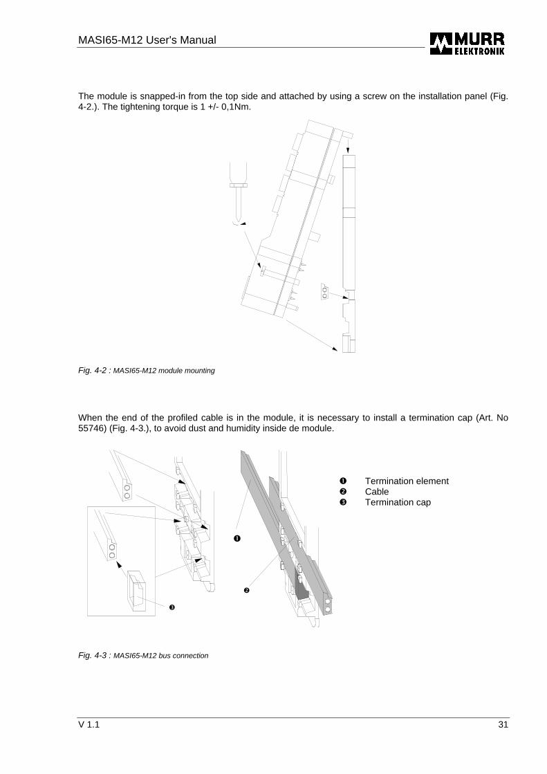
The module is snapped-in from the top side and attached by using a screw on the installation panel (Fig. 4-2.). The tightening torque is 1 +/- 0,1Nm.
Fig. 4-2 : MASI65-M12 module mounting
When the end of the profiled cable is in the module, it is necessary to install a termination cap (Art. No 55746) (Fig. 4-3.), to avoid dust and humidity inside de module. � Termination element � Cable � Termination cap
Fig. 4-3 : MASI65-M12 bus connection
�
�
�

MASI65-M12 User's manual
32 V 1.1
4.1.3 Bus branching function MASI65-M12 modules support the bus branching function.
�� �
�
ASI
�
ASI
Fig. 4-4 : Bus branching
�-� : AS-I bus flat cables �-� : Cable guide � : AS-I duct openings, internal link between the upper and lower bus connection The following modules support the bus branching function : 55572 MASI65-M12 DI8 0,4A 55573 MASI65-M12 DI4 0,2A 55622 MASI65-M12 DI4 0,2A 55623 MASI65-M12 DI8 0,4A
The bus branching function can partially induce high cumulated currents ! In all cases, make sure that the cumulated current is lower than 4 A.
MASI65-M12 User's Manual
V 1.1 33
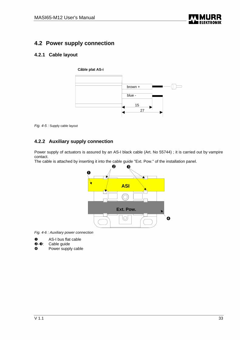
4.2 Power supply connection 4.2.1 Cable layout
1527
Câble plat AS-i
brown +
blue -
Fig. 4-5 : Supply cable layout
4.2.2 Auxiliary supply connection Power supply of actuators is assured by an AS-I black cable (Art. No 55744) ; it is carried out by vampire contact. The cable is attached by inserting it into the cable guide "Ext. Pow." of the installation panel.
�� �
�
ASI
Ext. Pow.
Fig. 4-6 : Auxiliary power connection
� AS-I bus flat cable �-�: Cable guide � Power supply cable

MASI65-M12 User's manual
34 V 1.1
When the end of the profiled cable is in the module, it is necessary to install a termination cap (Art. No 55746), to avoid dust and humidity inside de module. � Termination element � Cable � Termination cap
Fig. 4-7 : Power supply connection
Routing the power supply forward induces partially high cumulated currents ! In all cases it must be assured not to exceed the max. admissible current of cables.
�
�
�

MASI65-M12 User's Manual
V 1.1 35
4.3 Sensor and transmitter connection According to the module type, the power supply of connected sensors or transmitters is provided by the AS-Interface system power supply unit or by auxiliary supplies.
Supply of sensors/transmitters MASI65-M12 from the system Art. No : 55570
Art. No : 55571 Art. No : 55572 Art. No : 55573 Art. No : 55610 Art. No : 55612 Art. No : 55618 Art. No : 55622 Art. No : 55623 Art. No : 55624 Art. No : 55625 Art. No : 55628 Art. No : 55629 Art. No : 55675 Art. No : 55676
from auxiliary supply Art. No : 55619 Art. No : 55677
Table 4.3–1: List of modules
The 24V DC power supply of sensors is furnished by the AS-Interface system power supply unit and is electronically protected against overload and short-circuit. All sensors and transmitters connected to a Murrelektronik AS-Interface module are supplied by the same power source.
The power supply of sensors from the system's supply unit is not grounded. Never connect the sensor supply or sensors/transmitters to other modules.

MASI65-M12 User's manual
36 V 1.1
4.3.1 Pin arrangement of the round plug connector M12 with single signal as-signment
On standard modules, the pins 2 and 4 of the round plug connector M12 are strapped.
1 2
345
Fig. 4-8 : Pin arrangement of the round plug connectors M12 on MASI65-M12 modules
1: Sensor supply + 2: Strapping to pin 4 3: Sensor supply - 4: Input signal 5: FE 4.3.2 Pin arrangement of the round plug connector M12 with double signal as-
signment On modules with double signal assignment (Y wiring) the inputs of the round plug connectors M12 odd numbers (1,3,5,7) (pin 4) and the pin 2 of the round plug connectors M12 even numbers (0,2,4,6) are strapped.
12
345
1 2
34
5
Fig. 4-9 : Pin arrangement of the round plug connectors M12 with Y wiring
Inputs : I0, I2, I4, I6, Inputs : I1, I3, I5, I7 1 : Sensor supply + 1 : Sensor supply + 2 : Input signal I1,I3,I5,I7 2 : Not allocated 3 : Sensor supply - 3 : Sensor supply - 4 : Input signal I0, I2, I4, I6 4 : Input signal I1, I3, I5, I7 5 : FE 5 : FE
When connecting sensors, make sure not to twist the round plug connector M12 but only the ring nut. Round plug connectors M12 that are not used, must be obturated by a M12 cap (Art. N° 55468) to ensure the housing protection (IP).

MASI65-M12 User's Manual
V 1.1 37
4.4 Actuator connection (loads) The loads connected to the MASI65-M12 module are supplied by auxiliary power supply. For MASI65-M12 modules the output voltage is electronically protected against short-circuit and overload. The max. admissible load on outputs goes from 0,5A to 2A. The capacity of outputs is indicated in the installation manual of each module.
The module outputs of the MASI65-M12 range and the corresponding potentials must in no case be galvanic-connected to the inputs or outputs of other AS-Interface modules 4.4.1 Pin arrangement of the round plug connector M12 with single signal as-
signment On standard modules the output signal is allocated to pin 4 of the round plug connector M12.
1 2
345
Fig 4-10 : Pin arrangement of the round plug connector M12 on a standard module
1 : Not allocated 2 : Not allocated 3 : 0 V 4 : Output signal 5 : FE 4.4.2 Pin arrangement of the round plug connector M12 with double signal as-
signment On modules with double signal assignment (Y wiring) the outputs of the round plug connectors M12 odd numbers (O1,O3,O5,O7) (pin 4) and pin 2 of the round plug connectors M12 even numbers (O0,O2,O4,O6) are strapped.
12
345
1 2
34
5
Fig. 4-11: Pin arrangement of the round plug connectors M12 with Y wiring
Outputs : O0,O2, O4, O6 Outputs : O1, O3, O5, O7 1 : Not allocated 1 : Not allocated 2 : Output signal O1, O3, O5, O7 2 : Not allocated 3 : 0 V 3 : 0 V 4 : Output signal O0,O2, O4, O6 4 : Output signal O1, O3,O5,O7 5 : FE 5 : FE
MASI65-M12 User's manual
38 V 1.1
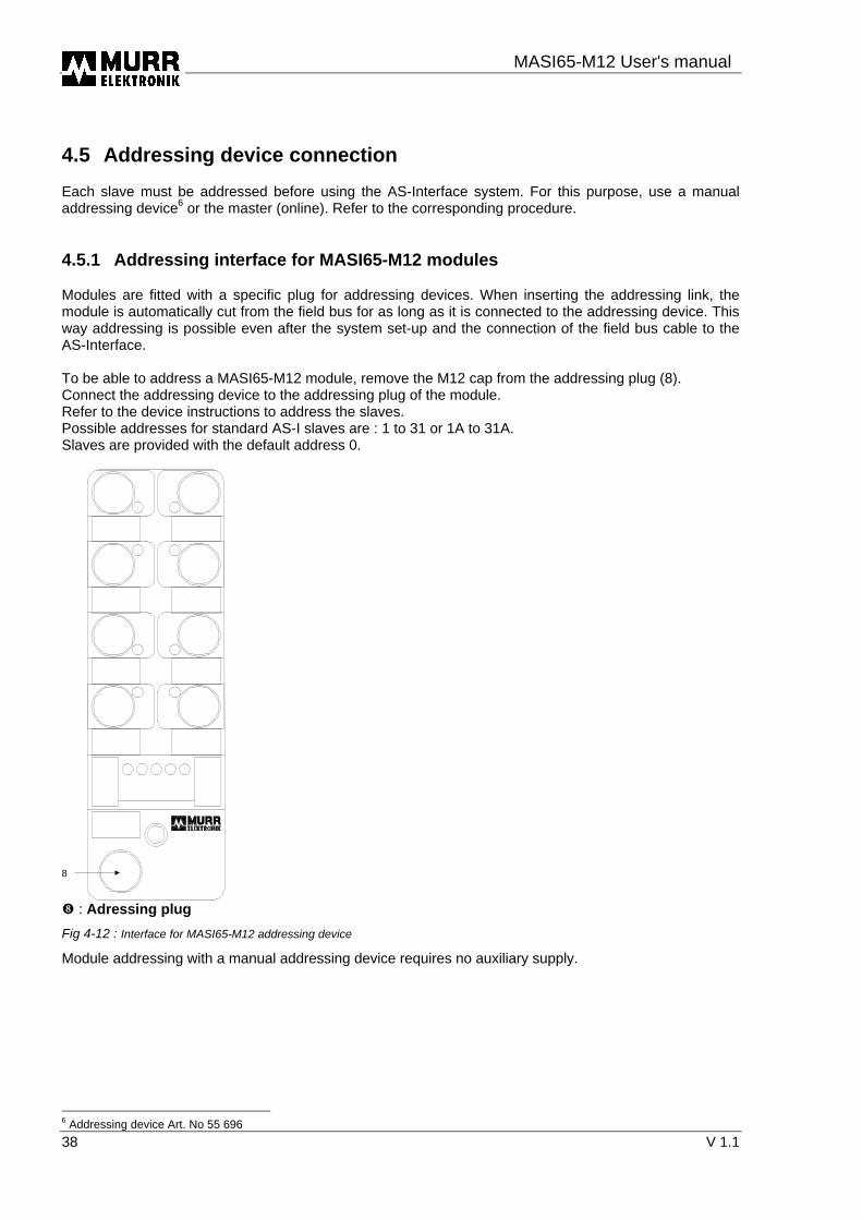
4.5 Addressing device connection Each slave must be addressed before using the AS-Interface system. For this purpose, use a manual addressing device6 or the master (online). Refer to the corresponding procedure. 4.5.1 Addressing interface for MASI65-M12 modules Modules are fitted with a specific plug for addressing devices. When inserting the addressing link, the module is automatically cut from the field bus for as long as it is connected to the addressing device. This way addressing is possible even after the system set-up and the connection of the field bus cable to the AS-Interface. To be able to address a MASI65-M12 module, remove the M12 cap from the addressing plug (8). Connect the addressing device to the addressing plug of the module. Refer to the device instructions to address the slaves. Possible addresses for standard AS-I slaves are : 1 to 31 or 1A to 31A. Slaves are provided with the default address 0.
8
� : Adressing plug
Fig 4-12 : Interface for MASI65-M12 addressing device
Module addressing with a manual addressing device requires no auxiliary supply.
6 Addressing device Art. No 55 696

MASI65-M12 User's Manual
V 1.1 39
5 Diagnosis displays Diagnostic information is an important prerequisite for easy setup. Errors can be quickly identified and rectified through clear information regarding the field bus system, the I/O module and connected peripheral components such as sensors and actuators. All MASI65-M12 series modules feature separate, clearly arranged displays for bus status, device status and I/O status. These displays are located on the front of the module housing.
1
1
2
3
�: LED Status display �: LED Voltage display �: LED Diagnosis display
Fig. 5-1 : Diagnosis displays MVK12

MASI65-M12 User's manual
40 V 1.1
5.1 Bus / Device status displays The LED's on the front of the module are marked ('AS-I' and 'Err') for clear information and represent a static or flashing LED display.
AS-I (green)
ERR (red)
Status
¡ ¡ absence of AS-I operating voltage ¡ no data communication ¡ module OK ¤ slave with address 0 ¡ ¤ Sensor supply is shorted / overloaded ¡ off ¤ flashing on
Table 5.1–1: Bus / Device status displays
5.2 I/O status display A status display is allocated individually to each input and output. According to the function the display is as follows : 'I1...In' for inputs or 'O1…On' for outputs. The display is located directly next to the corre-sponding M12 socket and makes it possible to recognize the status of peripheral components such as sensors and actuators.
LED (yellow) Status ¡ input / output deactivated input / output activated
¡: off : on
Table 5.2–1 : I/O status display
5.3 Auxiliary supply The power supply of the modules are equipped with an auxiliary supply (green LED). In this case, possible undervoltage is not detected. The auxiliary supply must be galvanic-separated according to IEC 364-4-1 (PELV).

MASI65-M12 User's Manual
V 1.1 41
6 Short-circuit/Overload response 6.1 Sensor / transmitter supply 6.1.1 MASI65-M12 standard slaves with SAP4.0 A short-circuit or an overload on the sensor supply causes a reset, which disconnects the AS-I slave from the network ; the master considers this status as a configuration error. The master indicates configuration errors by static display of the „config err“ LED. The slave indicates the configuration error by static display of the red LED „ERROR“. The „AS-I“ LED is off. When the cause of the short-circuit or overload has been corrected, the error status is automatically reset. 6.1.2 MASI65-M12 standard and AB slaves with SAP4.1 A short-circuit or an overload on the sensor supply causes a reset, which disconnects the AS-I slave from the network ; the master considers this status as a configuration error. The master indicates configuration errors by static display of the „config err“ LED. The slave indicates the configuration error by static display of the red LED „ERROR“. The „AS-I“ LED is off. When the cause of the short-circuit or overload has been corrected, the error status is automatically reset.
6.2 Outputs 6.2.1 MASI65-M12 standard slaves with SAP4.0 A short-circuit or an overload on the outputs causes a reset, which disconnects the AS-I slave from the network ; the master considers this status as a configuration error. The master indicates configuration errors by static display of the „config err“ LED. The slave indicates the configuration error by static display of the red LED „ERROR“. The „AS-I“ LED is off. When the cause of the short-circuit or overload has been corrected, the error status is automatically reset. 6.2.2 MASI65-M12 standard and AB slaves with SAP4.1 A short-circuit or an overload on the outputs corresponds to a peripheral error (FID) of the slave ; error indicated by the master if it is in conformity with the specification 2.1. The master indicates such errors by flashing display of the „config err“ LED. The slave indicates the error (FID) by alternative flashing display of the red LED „ERROR“ and the green LED „AS-I“. When the cause of the error has been corrected, the error status is automatically reset.
Standard slaves can be fitted with an AS-i SAP4.1 or AS-i SAP4.0 chip. SAP4.1 and SAP4.0 have different ID2 codes. The ID2 code is only indicated for SAP4.1 not for SAP4.0. You can find the ID codes in the corresponding installation manual.

MASI65-M12 User's manual
42 V 1.1
7 Data sheets for the MASI65-M12 series
7.1 Interference immunity data EMC EN 61000-4-3 RF-Field ......................................................10 V/m ENV 50204 RF-Field GSM .................................................10 V/m EN 61000-4-4 Burst............................................................± 1KV / ± 2KV EN 61000-4-2 ESD.............................................................± 4KV / ± 8KV EN 50081-1 Interference field strength ..............................QP 30 dBµV/m (30-230 MHz) ............................................................................................QP 37 dBµV/m (230-1000 MHz)

MASI65-M12 User's Manual
V 1.1 43
7.2 MASI65-M12 product-specific data Standard slaves 7.2.1 MASI65 DI8/0,4A Y 8xM12 Art. No. : 55570 ASI slave IP 67 with 8 digital inputs and Y distribution Technical data ASI connection ASI Bus voltage.................................................................. 26,5…31,6VDC Reverse polarity protection ................................................ integrated Profile (code IO/ID/ID2)...................................................... 2 x 0/1/F Total current usage ............................................................ max. 450 mA Connection (flat cable) ....................................................... ASI standard yellow cable .......................................................................................... 2x1,5mm² ASI+, ASI- Inputs Voltage range..................................................................... 0-30VDC according to IEC1131-2 - Signal 0 ............................................................................ lin ≤ 2 mA Uin ≤ 5 V - Signal 1 ............................................................................ lin ≥ 6 mA Uin ≥ 11 V Input current ....................................................................... ≤ 11 mA Max. admissible current ..................................................... max. 400mA Short-circuit/overload protection ........................................ integrated Inputs are galvanic-connected to the ASI bus. Do not connected them to an auxiliary power supply unit. Miscellaneous Temperature range ............................................................ 0...+60 °C Enclosure type according to DIN 40050............................. IP 67 Weight................................................................................ ~ 160 g Dimensions ........................................................................ 154x50x38 mm
MASI65-M12 User's manual
44 V 1.1
7.2.2 MASI65-M12 DI4/0,2A DO4/2A Y 8xM12 Art. No : 55 571 ASI slave IP67 with 4 digital inputs, 4 digital outputs TOR and Y distribution Technical data ASI connection ASI Bus voltage ..................................................................26,5…31,6VDC Reverse polarity protection................................................. integrated Profile (code IO/ID/ID2) ......................................................7/F/E Total current usage ............................................................max. 250 mA Connection (flat cable)........................................................ASI standard yellow cable ............................................................................................2x1,5mm² ASI+, ASI- Auxiliary supply Operating voltage range .....................................................Ub 20 … 30 VDC Reverse polarity protection................................................. integrated Connection (flat cable)........................................................ASI standard black cable ............................................................................................2x1,5mm² 24V, 0V The auxiliary supply must be galvanic-separated according to IEC 364-4-41 (PELV). Inputs Voltage range .....................................................................0-30VDC according to IEC1131-2 - Signal 0 ............................................................................ lin ≤ 2 mA Uin ≤ 5 V - Signal 1 ............................................................................ lin ≥ 6 mA Uin ≥ 11 V Input current .......................................................................≤ 11 mA Max. admissible current .....................................................max. 200mA Short-circuit/overload protection......................................... integrated Inputs are galvanic-connnected to the ASI bus. Do not connect them to an auxiliary supply unit. Outputs Max. admissible current ..................................................... IL 2 A 50% ED Total current (max.). ...........................................................4 A Output voltage ....................................................................Ub - 0,8V typ. Switching frequency ...........................................................100 Hz at resistive load ............................................................................................0,2 Hz at inductive load Short-circuit protection........................................................ integrated Overload protection ............................................................2 A Miscellaneous Temperature range.............................................................0...+60 °C Enclosure type according to DIN 40050 ............................. IP 67 Weight ................................................................................~ 160 g Dimensions.........................................................................154x50x38 mm
Nr. E201820 Nr. 32402

MASI65-M12 User's Manual
V 1.1 45
7.2.3 MASI65 DI8/0,4A BV Y 8xM12 Art. No : 55572 ASI slave IP67 with 8 digitial inputs, bus branching function and Y distribution Technical data ASI connection ASI Bus voltage.................................................................. 26,5…31,6VDC Reverse polarity protection ................................................ integrated Profile (code IO/ID/ID2)...................................................... 2 x 0/1/F Total current usage ............................................................ max. 450 mA Connection (flat cable) ....................................................... ASI standard yellow cable ........................................................................................... 2x1,5mm² ASI+, ASI- Inputs Voltage range..................................................................... 0-30VDC according to IEC1131-2 - Signal 0 ............................................................................ lin ≤ 2 mA Uin ≤ 5 V - Signal 1 ............................................................................ lin ≥ 6 mA Uin ≥ 11 V Input current ....................................................................... ≤ 11 mA Max. admissible current ..................................................... max. 400mA Short-circuit/overload protection ........................................ integrated Inputs are galvanic-connected to the ASI bus. Do not connect them to an auxiliary supply unit. Miscellaneous Temperature range ............................................................ 0...+60 °C Enclosure type according to DIN 40050............................. IP 67 Weight................................................................................ ~ 160 g Dimensions ........................................................................ 154x50x38 mm
Nr. E201820 Nr. 32402

MASI65-M12 User's manual
46 V 1.1
7.2.4 MASI65 DI4/0,2A BV Y 4xM12 Art. No : 55573 ASI slave IP67 with 4 digital inputs, bus branching function and Y distribution Technical data ASI connection ASI Bus voltage ..................................................................26,5…31,6VDC Reverse polarity protection................................................. integrated Profile (code IO/ID/ID2) ......................................................0/1/F Total current usage ............................................................max. 250 mA Connection (flat cable)........................................................ASI standard yellow cable ............................................................................................2x1,5mm² ASI+, ASI- Inputs Voltage range .....................................................................0-30VDC according to IEC1131-2 - Signal 0 ............................................................................ lin ≤ 2 mA Uin ≤ 5 V - Signal 1 ............................................................................ lin ≥ 6 mA Uin ≥ 11 V Input current .......................................................................≤ 11 mA Max. admissible current .....................................................max. 200mA Short-circuit/overload protection......................................... integrated Inputs are galvanic-connnected to the ASI bus. Do not connect them to an auxiliary supply unit. Miscellaneous Temperature range.............................................................0...+60C Enclosure type according to DIN 40050 ............................. IP 67 Weight ................................................................................~ 100 g Dimensions.........................................................................105x50x38 mm
Nr. E201820 Nr. 32402

MASI65-M12 User's Manual
V 1.1 47
7.2.5 MASI65 DI4/0,2A 4xM12 Art. No : 55610 ASI slave IP67 with 4 digital inputs Technical data ASI connection ASI Bus voltage.................................................................. 26,5…31,6VDC Reverse polarity protection ................................................ integrated Profile (code IO/ID/ID2)...................................................... 0/0/F Total current usage ............................................................ max. 250 mA Connection (flat cable) ....................................................... ASI standard yellow cable ........................................................................................... 2x1,5mm² ASI+, ASI- Inputs Voltage range..................................................................... 0-30VDC according to IEC1131-2 - Signal 0 ............................................................................ lin ≤ 2 mA Uin ≤ 5 V - Signal 1 ............................................................................ lin ≥ 6 mA Uin ≥ 11 V Input current ....................................................................... ≤ 11 mA Max. admissible current ..................................................... max. 200mA Short-circuit/overload protection ........................................ integrated Inputs are galvanic-connected to the ASI bus. Do not connect them to an auxiliary supply unit. Miscellaneous Temperature range ............................................................ 0...+60 °C Enclosure type according to DIN 40050............................. IP 67 Weight................................................................................ ~ 100 g Dimensions ........................................................................ 105x50x38 mm
Nr. E201820 Nr. 32402

MASI65-M12 User's manual
48 V 1.1
7.2.6 MASI65 DI8/0,4A 8xM12 Art. No : 55612 ASI slave IP67 with 8 digital inputs Technical data ASI connection ASI Bus voltage ..................................................................26,5…31,6VDC Reverse polarity protection................................................. integrated Profile (code IO/ID/ID2) ......................................................2 x 0/0/F Total current usage ............................................................max. 450 mA Connection (flat cable)........................................................ASI standard yellow cable ............................................................................................2x1,5mm² ASI+, ASI- Inputs Voltage range .....................................................................0-30VDC according to IEC1131-2 - Signal 0 ............................................................................ lin ≤ 2 mA Uin ≤ 5 V - Signal 1 ............................................................................ lin ≥ 6 mA Uin ≥ 11 V Input current .......................................................................≤ 11 mA Max. admissible current .....................................................max. 400mA Short-circuit/overload protection......................................... integrated Inputs are galvanic-connected to the ASI bus. Do not connect them to an auxiliary supply unit. Miscellaneous Temperature range.............................................................0...+60 °C Enclosure type according to DIN 40050 ............................. IP 67 Weight ................................................................................~ 160 g Dimensions.........................................................................154x50x38 mm
Nr. E201820 Nr. 32402

MASI65-M12 User's Manual
V 1.1 49
7.2.7 MASI65 DO4/0,5A 4xM12 Art. No : 55614 ASI slave IP67 with 4 digital outputs Technical data ASI connection ASI Bus voltage.................................................................. 26,5…31,6VDC Reverse polarity protection ................................................ integrated Profile (code IO/ID/ID2)...................................................... 8/0/E Total current usage ............................................................ max. 50 mA Connection (flat cable) ....................................................... ASI standard yellow cable ........................................................................................... 2x1,5mm² ASI+, ASI- Auxiliary supply Operating voltage range..................................................... Ub 20 … 30 VDC Reverse polarity protection ................................................ integrated Connection (flat cable) ....................................................... ASI standard black cable ........................................................................................... 2x1,5mm² 24V, 0V The auxiliary supply must be galvanic-separated according to IEC 364-4-41 (PELV). Outputs Max. admissible current ..................................................... IL 0,5 A 100% ED Total admissible current..................................................... 2 A Output voltage.................................................................... Ub - 0,8V typ. Switching frequency ........................................................... 100 Hz at resistive load ........................................................................................... 0,2 Hz at inductive load Short-circuit protection ....................................................... integrated Overload protection............................................................ 1 A Miscellaneous Temperature range ............................................................ 0...+60 °C Enclosure type according to DIN 40050............................. IP 67 Weight................................................................................ ~ 100 g Dimensions ........................................................................ 105x50x38 mm
Nr. E201820 Nr. 32402

MASI65-M12 User's manual
50 V 1.1
7.2.8 MASI65 DO4/2A 4xM12 Art. No : 55615 ASI slave IP67 with 4 digital outputs Technical data ASI connection ASI Bus voltage ..................................................................26,5…31,6VDC Reverse polarity protection................................................. integrated Profile (code IO/ID/ID2) ......................................................8/0/E Total current usage ............................................................max. 50 mA Connection (flat cable)........................................................ASI standard yellow cable ............................................................................................2x1,5mm² ASI+, ASI- Auxiliary supply Operating voltage range .....................................................Ub 20 … 30 VDC Reverse polarity protection................................................. integrated Connection (flat cable)........................................................ASI standard black cable ............................................................................................2x1,5mm² 24V, 0V The auxiliary supply must be galvanic-separated according to IEC 364-4-41 (PELV). Outputs Max. admissible current ..................................................... IL 2 A 50% ED Total admissible current .....................................................4 A Output voltage ....................................................................Ub - 0,8V typ. Switching frequency ...........................................................100 Hz at resistive load ............................................................................................0,2 Hz at inductive load Short-circuit protection........................................................ integrated Overload protection ............................................................2 A Miscellaneous Temperature range.............................................................0...+60 °C Enclosure type according to DIN 40050 ............................. IP 67 Weight ................................................................................~ 100 g Dimensions.........................................................................105x50x38 mm
Nr. E201820 Nr. 32402

MASI65-M12 User's Manual
V 1.1 51
7.2.9 MASI65 DO8/0,5A 8xM12 Art. No : 55616 ASI slave IP67 with 8 digital outputs Technical data ASI connection ASI Bus voltage.................................................................. 26,5…31,6VDC Reverse polarity protection ................................................ integrated Profile (code IO/ID/ID2)...................................................... 2 x 8/0/E Total current usage ............................................................ max. 50 mA Connection (flat cable) ....................................................... ASI standard yellow cable ........................................................................................... 2x1,5mm² ASI+, ASI- Auxiliary supply Operating voltage range..................................................... Ub 20 … 30 VDC Reverse polarity protection ................................................ integrated Connection (flat cable) ....................................................... ASI standard black cable ........................................................................................... 2x1,5mm² 24V, 0V The auxiliary supply must be galvanic-separated according to IEC 364-4-41 (PELV). Outputs Max. admissible current ..................................................... IL 0,5 A 100% ED Total admissible current..................................................... 4 A Output voltage.................................................................... Ub - 0,8V typ. Switching frequency ........................................................... 100 Hz at resistive load ........................................................................................... 0,2 Hz at inductive load Short-circuit protection ....................................................... integrated Overload protection............................................................ 1 A Miscellaneous Temperature range ............................................................ 0...+60 °C Enclosure type according to DIN 40050............................. IP 67 Weight................................................................................ ~ 140 g Dimensions ........................................................................ 154x50x38 mm
Nr. E201820 Nr. 32402
MASI65-M12 User's manual
52 V 1.1
7.2.10 MASI65 DI4/0,2A DO4/0,5A 8xM12 Art. No : 55618 ASI slave IP67 with 4 digital inputs / 4 digital outputs Technical data ASI connection ASI Bus voltage ..................................................................26,5…31,6VDC Reverse polarity protection................................................. integrated Profile (code IO/ID/ID2) ......................................................7/0/E Total current usage ............................................................max. 250 mA Connection (flat cable)........................................................ASI standard yellow cable ............................................................................................2x1,5mm² ASI+, ASI- Auxiliary supply Operating voltage range .....................................................Ub 20 … 30 VDC Reverse polarity protection................................................. integrated Connection (flat cable)........................................................ASI standard black cable ............................................................................................2x1,5mm² 24V, 0V The auxiliary supply must be galvanic-separated according to IEC 364-4-41 (PELV). Inputs Voltage range .....................................................................0-30VDC according to IEC1131-2 - Signal 0 ............................................................................ lin ≤ 2 mA Uin ≤ 5 V - Signal 1 ............................................................................ lin ≥ 6 mA Uin ≥ 11 V Input current .......................................................................≤ 11 mA Max. admissible current ....................................................max. 200mA Short-circuit/overload protection......................................... integrated Inputs are galvanic-connected to the ASI bus. Do not connect them to an auxiliary supply unit. Outputs Max. admissible current ..................................................... IL 0,5 A 100% ED Total admissible current .....................................................4 A Output voltage ....................................................................Ub - 0,8V typ. Switching frequency ...........................................................100 Hz at resistive load ............................................................................................0,2 Hz at inductive load Short-circuit protection........................................................ integrated Overload protection ............................................................1 A Miscellaneous Temperature range.............................................................0...+60 °C Enclosure type according to DIN 40050 ............................. IP 67 Weight ................................................................................~ 160 g Dimensions.........................................................................154x50x38 mm
Nr. E201820 Nr. 32402

MASI65-M12 User's Manual
V 1.1 53
7.2.11 MASI65 DI4/1,6A DO4/2A 8xM12 Art. No : 55619 ASI slave IP67 with 4 digital inputs / 4 digital outputs Technical data ASI connection ASI Bus voltage.................................................................. 26,5…31,6VDC Reverse polarity protection ................................................ integrated Profile (code IO/ID/ID2)...................................................... 7/0/E Total current usage ............................................................ max. 50 mA Connection (flat cable) ....................................................... ASI standard yellow cable ........................................................................................... 2x1,5mm² ASI+, ASI- Auxiliary supply Operating voltage range..................................................... Ub 20 … 30 VDC Reverse polarity protection ................................................ integrated Connection (flat cable) ....................................................... ASI standard black cable ........................................................................................... 2x1,5mm² 24V, 0V The auxiliary supply must be galvanic-separated according to IEC 364-4-41 (PELV). Inputs Voltage range..................................................................... 0-30VDC according to IEC1131-2 - Signal 0 ............................................................................ lin ≤ 2 mA Uin ≤ 5 V - Signal 1 ............................................................................ lin ≥ 6 mA Uin ≥ 11 V Input current ....................................................................... ≤ 11 mA Max. admissible current ..................................................... max. 1,6A Short-circuit/overload protection ........................................ integrated Inputs are supplied by the auxiliary supply (Ub). Outputs Max. admissible current ..................................................... IL 2 A 50% ED Total admissible current..................................................... 4 A Output voltage.................................................................... Ub - 0,8V typ. Switching frequency ........................................................... 100 Hz at resistive load ........................................................................................... 0,2 Hz at inductive load Short-circuit protection ....................................................... integrated Overload protection............................................................ 2 A Miscellaneous Temperature range ............................................................ 0...+60 °C Enclosure type according to DIN 40050............................. IP 67 Weight................................................................................ ~ 160 g Dimensions ........................................................................ 154x50x38 mm
Nr. E201820 Nr. 32402

MASI65-M12 User's manual
54 V 1.1
7.2.12 MASI65 DI4/0,2A BV 4xM12 Art. No : 55622 ASI slave IP67 with 4 digital inputs and bus branching function. Technical data ASI connection ASI Bus voltage ..................................................................26,5…31,6VDC Reverse polarity protection................................................. integrated Profile (code IO/ID/ID2) ......................................................0/0/F Total consumption ..............................................................max. 250 mA Connection (flat cable)........................................................ASI standard yellow cable ............................................................................................2x1,5mm² ASI+, ASI- Inputs Voltage range .....................................................................0-30VDC according to IEC1131-2 - Signal 0 ............................................................................ lin ≤ 2 mA Uin ≤ 5 V - Signal 1 ............................................................................ lin ≥ 6 mA Uin ≥ 11 V Input current .......................................................................≤ 11 mA Max. admissible current .....................................................max. 200mA Short-circuit/overload protection......................................... integrated Inputs are galvanic-connected to the ASI bus. Do not connect them to an auxiliary supply unit. Miscellaneous Temperature range.............................................................0...+60 °C Enclosure type according to DIN 40050 ............................. IP 67 Weight ................................................................................~ 100 g Dimensions.........................................................................105x50x38 mm
Nr. E201820 Nr. 32402
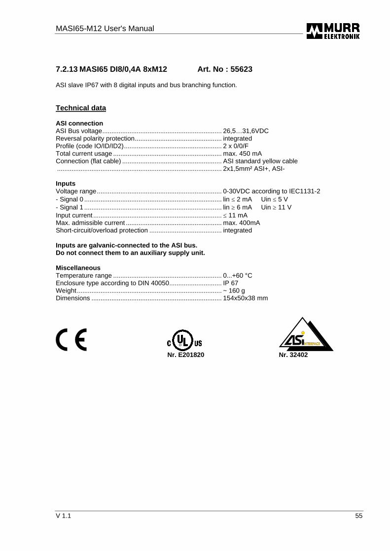
MASI65-M12 User's Manual
V 1.1 55
7.2.13 MASI65 DI8/0,4A 8xM12 Art. No : 55623 ASI slave IP67 with 8 digital inputs and bus branching function. Technical data ASI connection ASI Bus voltage.................................................................. 26,5…31,6VDC Reversal polarity protection................................................ integrated Profile (code IO/ID/ID2)...................................................... 2 x 0/0/F Total current usage ............................................................ max. 450 mA Connection (flat cable) ....................................................... ASI standard yellow cable ........................................................................................... 2x1,5mm² ASI+, ASI- Inputs Voltage range..................................................................... 0-30VDC according to IEC1131-2 - Signal 0 ............................................................................ lin ≤ 2 mA Uin ≤ 5 V - Signal 1 ............................................................................ lin ≥ 6 mA Uin ≥ 11 V Input current ....................................................................... ≤ 11 mA Max. admissible current ..................................................... max. 400mA Short-circuit/overload protection ........................................ integrated Inputs are galvanic-connected to the ASI bus. Do not connect them to an auxiliary supply unit. Miscellaneous Temperature range ............................................................ 0...+60 °C Enclosure type according to DIN 40050............................. IP 67 Weight................................................................................ ~ 160 g Dimensions ........................................................................ 154x50x38 mm
Nr. E201820 Nr. 32402

MASI65-M12 User's manual
56 V 1.1
7.2.14 MASI65 DI4/0,2A DO4/2A 8xM12 Art. No : 55624 ASI slave IP67 with 4 digital inputs / 4 digital outputs. Technical data ASI connection ASI Bus voltage ..................................................................26,5…31,6VDC Reverse polarity protection................................................. integrated Profile (code IO/ID/ID2) ......................................................7/0/E Total current usage ............................................................max. 250 mA Connection (flat cable)........................................................ASI standard yellow cable ............................................................................................2x1,5mm² ASI+, ASI- Auxiliary sypply Operating voltage range .....................................................Ub 20 … 30 VDC Reverse polarity protection................................................. integrated Connection (flat cable)........................................................ASI standard black cable ............................................................................................2x1,5mm² 24V, 0V The auxiliary supply must be galvanic-separated according to IEC 364-4-41 (PELV). Inputs Voltage range .....................................................................0-30VDC according to IEC1131-2 - Signal 0 ............................................................................ lin ≤ 2 mA Uin ≤ 5 V - Signal 1 ............................................................................ lin ≥ 6 mA Uin ≥ 11 V Input current .......................................................................≤ 11 mA Max. admissible current .....................................................max. 200mA Short-circuit/overload protection......................................... integrated Inputs are galvanic-connected to the ASI bus. Do not connect them to an auxiliary supply unit. Outputs Max. admissible current ..................................................... IL 2 A 50% ED Total admissible current .....................................................4 A Output voltage ....................................................................Ub - 0,8V typ. Switching frequency ...........................................................100 Hz at resistive load ............................................................................................0,2 Hz at inductive load Short-circuit protection........................................................ integrated Overload protection ............................................................2 A Miscellaneous Temperature range.............................................................0...+60 °C Enclosure type according to DIN 40050 ............................. IP 67 Weight ................................................................................~ 160 g Dimensions.........................................................................154x50x38 mm
Nr. E201820 Nr. 32402

MASI65-M12 User's Manual
V 1.1 57
7.2.15 MASI65 DI2/0,2A DO2/2A 4xM12 Art. No : 55625 ASI slave IP67 with 2 digital inputs / 2 digital outputs. Technical data ASI connection ASI Bus voltage.................................................................. 26,5…31,6VDC Reverse polarity protection ................................................ integrated Profile (code IO/ID/ID2)...................................................... 3/0/E Total current usage ............................................................ max. 250 mA Connection (flat cable) ....................................................... ASI standard yellow cable ........................................................................................... 2x1,5mm² ASI+, ASI- Auxiliary supply Operating voltage range..................................................... Ub 20 … 30 VDC Reverse polarity protection ................................................ integrated Connection (flat cable) ....................................................... ASI standard black cable ........................................................................................... 2x1,5mm² 24V, 0V The auxiliary supply must be galvanic-separated according to IEC 364-4-41 (PELV). Inputs Volgage range.................................................................... 0-30VDC according to IEC1131-2 - Signal 0 ............................................................................ lin ≤ 2 mA Uin ≤ 5 V - Signal 1 ............................................................................ lin ≥ 6 mA Uin ≥ 11 V Input current ....................................................................... ≤ 11 mA Max. admissible current ..................................................... max. 200mA Short-circuit/overload protection ........................................ integrated Inputs are galvanic-connected to the ASI bus. Do not connect them to an auxiliary supply unit. Outputs Max. admissible current ..................................................... IL 2 A 100% ED Total admissible current..................................................... 4 A Output voltage.................................................................... Ub - 0,8V typ. Switching frequency ........................................................... 100 Hz at resistive load ........................................................................................... 0,2 Hz at inductive load Short-circuit protection ....................................................... integrated Overload protection............................................................ 2 A Miscellaneous Temperature range ............................................................ 0...+60 °C Enclosure type according to DIN 40050............................. IP 67 Weight................................................................................ ~ 100 g Dimensions ........................................................................ 105x50x38 mm
Nr. E201820 Nr. 32402

MASI65-M12 User's manual
58 V 1.1
7.2.16 MASI65 DI4/0,2A DO4/0,5A Y 8xM12 Art. No : 55628 ASI slave IP67 with 4 digital inputs / 4 digital outputs and Y distribution. Technical data ASI connection ASI Bus voltage ..................................................................26,5…31,6VDC Reverse polarity protection................................................. integrated Profile (code IO/ID/ID2) ......................................................7/F/E Total current usage ............................................................max. 250 mA Connection (flat cable)........................................................ASI standard yellow cable 2x1,5mm² ASI+, ASI- Auxiliary supply Operating voltage range .....................................................Ub 20 … 30 VDC Reverse polarity protection................................................. integrated Connection (flat cable)........................................................ASI standard black cable 2x1,5mm² 24V, 0V The auxiliary supply must be galvanic-separated according to IEC 364-4-41 (PELV). Inputs Voltage range .....................................................................0-30VDC according to IEC1131-2 - Signal 0 ............................................................................ lin ≤ 2 mA Uin ≤ 5 V - Signal 1 ............................................................................ lin ≥ 6 mA Uin ≥ 11 V Input current .......................................................................≤ 11 mA Max. admissible current .....................................................max. 200mA Short-circuit/overload protection......................................... integrated Inputs are galvanic-connected to the ASI bus. Do not connect them to an auxiliary supply unit. Outputs Max. admissible current ..................................................... IL 0,5 A 100% ED Total admissible current .....................................................2 A Output voltage ....................................................................Ub - 0,8V typ. Switching frequency ...........................................................100 Hz at resistive load ............................................................................................0,2 Hz at inductive load Short-circuit protection........................................................ integrated Overload protection ............................................................1 A Miscellaneous Temperature range.............................................................0...+60 °C Enclosure type according to DIN 40050 ............................. IP 67 Weight ................................................................................~ 160 g Dimensions.........................................................................154x50x38 mm
Nr. E201820 Nr. 32402

MASI65-M12 User's Manual
V 1.1 59
7.2.17 MASI65 DI4/0,2A Y 4xM12 Art. No : 55629 ASI slave IP67 with 4 digital inputs and Y distribution. Technical data ASI connection ASI Bus voltage.................................................................. 26,5…31,6VDC Reverse polarity protection ................................................ integrated Profile (code IO/ID/ID2)...................................................... 0/1/F Total current usage ............................................................ max. 250 mA Connection (flat cable) ....................................................... ASI standard yellow cable ........................................................................................... 2x1,5mm² ASI+, ASI- Inputs Voltage range..................................................................... 0-30VDC according to IEC1131-2 - Signal 0 ............................................................................ lin ≤ 2 mA Uin ≤ 5 V - Signal 1 ............................................................................ lin ≥ 6 mA Uin ≥ 11 V Input current ....................................................................... ≤ 11 mA Max. admissible current ..................................................... max. 200mA Short-circuit/overloard protection ....................................... integrated Inputs are galvanic-connected to the ASI bus. Do not connect them to an auxiliary supply unit. Miscellaneous Temperature range ............................................................ 0...+60 °C Enclosure type according to DIN 40050............................. IP 67 Weight................................................................................ ~ 100 g Dimensions ........................................................................ 105x50x38 mm
Nr. E201820 Nr. 32402

MASI65-M12 User's manual
60 V 1.1
7.3 MVK12 AB product-specific technical data AB slaves 7.3.1 MASI65 DI4/0,2A DO3/2A AB Y 8xM12 Art. No : 55 675 ASI slave IP67 with 4 digital inputs, 3 digital outputs and Y distribution. Technical data ASI connection ASI Bus voltage ..................................................................26,5…31,6VDC Reverse polarity protection................................................. integrated Profile (code IO/ID/ID2) ......................................................7/A/E Total current usage ............................................................max. 250 mA Connection (flat cable)........................................................ASI standard yellow cable ............................................................................................2x1,5mm² ASI+, ASI- Auxiliary supply Operating voltage range .....................................................Ub 20 … 30 VDC Reverse polarity protection................................................. integrated Connection (flat cable)........................................................ASI standard black cable ............................................................................................2x1,5mm² 24V, 0V The auxiliary supply must be galvanic-separated according to IEC 364-4-41 (PELV). Inputs Voltage range .....................................................................0-30VDC according to IEC1131-2 - Signal 0 ............................................................................ lin ≤ 2 mA Uin ≤ 5 V - Signal 1 ............................................................................ lin ≥ 6 mA Uin ≥ 11 V Input current .......................................................................≤ 11 mA Max. admissible current .....................................................max. 200mA Short-circuit/overload protection......................................... integrated Inputs are galvanic-connected to the ASI bus. Do not connect them to an auxiliary supply unit. Outputs Max. admissible current ..................................................... IL 0,5 A 100% ED Total admissible current .....................................................2 A Output voltage ....................................................................Ub - 0,8V typ. Switching frequency ...........................................................100 Hz at resistive load ............................................................................................0,2 Hz at inductive load Short-circuit protection........................................................ integrated Overload protection ............................................................1 A Miscellaneous Temperature range.............................................................0...+60 °C Enclosure type according to DIN 40050 ............................. IP 67 Weight ................................................................................~ 160 g Dimensions.........................................................................154x50x38 mm
Nr. E201820 Nr. 32402 7.3.2 MASI65 DI8/0,2A AB Y 8xM12 Art. No : 55676
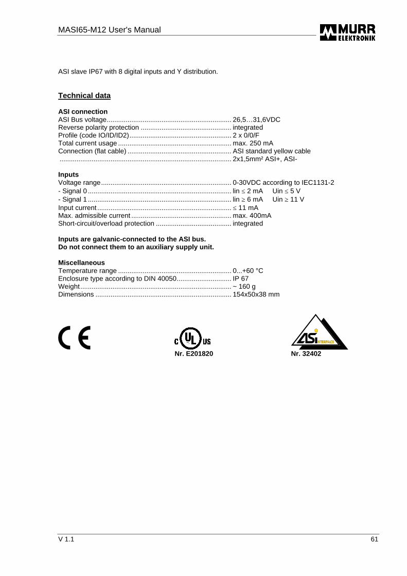
MASI65-M12 User's Manual
V 1.1 61
ASI slave IP67 with 8 digital inputs and Y distribution. Technical data ASI connection ASI Bus voltage.................................................................. 26,5…31,6VDC Reverse polarity protection ................................................ integrated Profile (code IO/ID/ID2)...................................................... 2 x 0/0/F Total current usage ............................................................ max. 250 mA Connection (flat cable) ....................................................... ASI standard yellow cable ........................................................................................... 2x1,5mm² ASI+, ASI- Inputs Voltage range..................................................................... 0-30VDC according to IEC1131-2 - Signal 0 ............................................................................ lin ≤ 2 mA Uin ≤ 5 V - Signal 1 ............................................................................ lin ≥ 6 mA Uin ≥ 11 V Input current ....................................................................... ≤ 11 mA Max. admissible current ..................................................... max. 400mA Short-circuit/overload protection ........................................ integrated Inputs are galvanic-connected to the ASI bus. Do not connect them to an auxiliary supply unit. Miscellaneous Temperature range ............................................................ 0...+60 °C Enclosure type according to DIN 40050............................. IP 67 Weight................................................................................ ~ 160 g Dimensions ........................................................................ 154x50x38 mm
Nr. E201820 Nr. 32402

MASI65-M12 User's manual
62 V 1.1
7.3.3 MASI65 DI4/1,6A DO3/2A AB Y 8xM12 Art. No : 55677 ASI slave IP67 with 4 digital inputs, 3 digital outputs and Y distribution. Technical data ASI connection ASI Bus voltage ..................................................................26,5…31,6VDC Reverse polarity protection................................................. integrated Profile (code IO/ID/ID2) ......................................................7/0/E Total current usage ............................................................max. 50 mA Connection (flat cable)........................................................ASI standard yellow cable ............................................................................................2x1,5mm² ASI+, ASI- Auxiliary supply Operating voltage range .....................................................Ub 20 … 30 VDC Reverse polarity protection................................................. integrated Connection (flat cable)........................................................ASI standard black cable ............................................................................................2x1,5mm² 24V, 0V The auxiliary supply must be galvanic-separated according to IEC 364-4-41 (PELV). Inputs Voltage range .....................................................................0-30VDC according to IEC1131-2 - Signal 0 ............................................................................ lin ≤ 2 mA Uin ≤ 5 V - Signal 1 ............................................................................ lin ≥ 6 mA Uin ≥ 11 V Input current .......................................................................≤ 11 mA Max. admissible current .....................................................max. 1,6A Short-circuit/overload protection......................................... integrated Inputs are supplied by the auxiliary supply (Ub). Outputs Max. admissible current ..................................................... IL 2 A 50% ED Total admissible current .....................................................4 A Output voltage ....................................................................Ub - 0,8V typ. Switching frequency ...........................................................100 Hz at resistive load ............................................................................................0,2 Hz at inductive load Short-circuit protection........................................................ integrated Overload protection ............................................................2 A Miscellaneous Temperature range.............................................................0...+60 °C Enclosure type according to DIN 40050 ............................. IP 67 Weight ................................................................................~ 160 g Dimensions.........................................................................154x50x38 mm
Nr. E201820 Nr. 32402

MASI65-M12 User's Manual
V 1.1 63
8 Modules versions and features
8.1 MASI65-M12 : 8-way module
5
6
7
8
1
2
1
2
3
4
�: Status display elements �: Identification label �: Voltage LED �: Diagnostic LED �: Slave identification label �: Module identification label �: Central screw �: Addressing plug

MASI65-M12 User's manual
64 V 1.1
8.2 MASI65-M12 : 4-way module
23
1
4
5
7
8
6
� : Status display elements � : Identification label � : Diagnostic LED � : Slave identification label � : Module identification label � : Central screw � : Addressing plug

MASI65-M12 User's Manual
V 1.1 65
9 List of illustrations Fig. 2-1 : AS-Interface Fig. 2-2 : Marking ................................................................................................ 12 Fig. 2-3 : Topology of the AS-Interface system .......................................................................................... 13 Fig. 2-4 : AS-Interface cable ....................................................................................................................... 17 Fig. 2-5 : AS-Interface round cable according to DIN VDE 0281 Part 402................................................. 17 Fig. 2-6 : AS-Interface system power supply.............................................................................................. 18 Fig. 2-7 : Manual addressing device........................................................................................................... 21 Fig. 3-1 : Mounting of a MASI65-M12 8-way module ................................................................................. 26 Fig. 3-2 : Mounting of a MASI65-M12 4-way module ................................................................................. 27 Fig. 3-3 : Adapter for DIN-rail mounting...................................................................................................... 27 Fig. 3-4 : MASI65-M12 FE connection........................................................................................................ 29 Fig. 4-1 : ASI flat cable layout ..................................................................................................................... 30 Fig. 4-2 : MASI65-M12 module mounting ................................................................................................... 31 Fig. 4-3 : MASI65-M12 bus connection ...................................................................................................... 31 Fig. 4-4 : Bus branching.............................................................................................................................. 32 Fig. 4-5 : Supply cable layout ..................................................................................................................... 33 Fig. 4-6 : Auxiliary power connection.......................................................................................................... 33 Fig. 4-7 : Power supply connection............................................................................................................. 34 Fig. 4-8 : Pin arrangement of the round plug connectors M12 on MASI65-M12 modules ......................... 36 Fig. 4-9 : Pin arrangement of the round plug connectors M12 with Y wiring.............................................. 36 Fig 4-10 : Pin arrangement of the round plug connector M12 on a standard module................................ 37 Fig. 4-11: Pin arrangement of the round plug connectors M12 with Y wiring............................................. 37 Fig 4-12 : Interface for MASI65-M12 addressing device ............................................................................ 38 Fig. 5-1 : Diagnosis displays MVK12 .......................................................................................................... 39

MASI65-M12 User's manual
66 V 1.1
10 List of tables Table 2.2–1 : AS-Interface system data......................................................................................................14 Table 2.4–1 : Influence of various cross-sections .......................................................................................20 Table 4.3–1: List of modules .......................................................................................................................35 Table 5.1–1: Bus / Device status displays ..................................................................................................40 Table 5.2–1 : I/O status display...................................................................................................................40