handout 1 supplementary info to the design handout · supplementary info to the design handout...
TRANSCRIPT

Part IA Structural Design Course 2009/10
Handout 1
Supplementary Info to theDESIGN HANDOUT
Supervisor versionText and pictures in grey are omitted from the student version.
Fehmi Cirak, February 24, 2010

2 Part IA Structural Design Course 2009/10
Demonstrators:
Dr Fehmi Cirak ([email protected])Alex Macdonald ([email protected])
Problem:
Aluminium Truss Bridge
Copy here problem description from Cam’s handout.Todo
A highvoltage power mast as a sample of a truss structure.
Tasks
1. As a pair design an aluminium bridge structure to carry a specified load withoutfailure
2. Produce detailed manufacturing drawings
3. Build the structure in the workshop
4. Perform a cost analysis
5. Test the truss to destruction
6. Write an individual report
Prizes available for the best projects
Handout 1. Supplementary Info to theDESIGN HANDOUT 3
Project Timetable
Session 1:
Thursday, 22 October (11am–1pm)
• Project briefing
• Tour of the test rig (Structures Teaching Lab)
• Tutorial on member sizing and stability
• Work on design concepts
Session 2:
Thursday, 29 October (11am–1pm)
• Tutorial on detailed joint design
• Tour of the workshops
• Work on detailed design and calculations
Session 3:
Thursday, 5 November (11am–1pm)
• Briefing on manufacturing drawings
• Finish detailed design and calculations
• Work on manufacturing drawings
Session 4:
Thursday, 12 November (11am–1pm)
• Finish manufacturing drawings
Deadline for drawings: 5pm Monday 16 November
Put here a deadlines section from Cam’s notes. Todo
4 Part IA Structural Design Course 2009/10
Design Documentation
Lab books:
1. All notes, sketches and calculations should be located at one end of the lab book (noloose sheets)
2. All working should be tidy and legible with the design process clearly laid out
3. The final report should be written at the other end of the lab book
4. Word processing is permitted for the text (pasted into the lab book) but not forcalculations
5. All sketches, detailed drawings, component selection and calculations should be car-ried out by hand (no spreadsheets, CAD etc)
Detailed manufacturing drawings
• Use A3 size paper and drawing boards provided
(More details will be provided later.)
Don’t go over Cam’s notes. Just mention that they are required to
read it.Todo

Part IA Structural Design Course 2009/10
Handout 2
Member Sizing: Tension and Compression
Supervisor versionText and pictures in grey are omitted from the student version.
Fehmi Cirak, February 24, 2010
6 Part IA Structural Design Course 2009/10
2.1 Introduction: Truss Structures
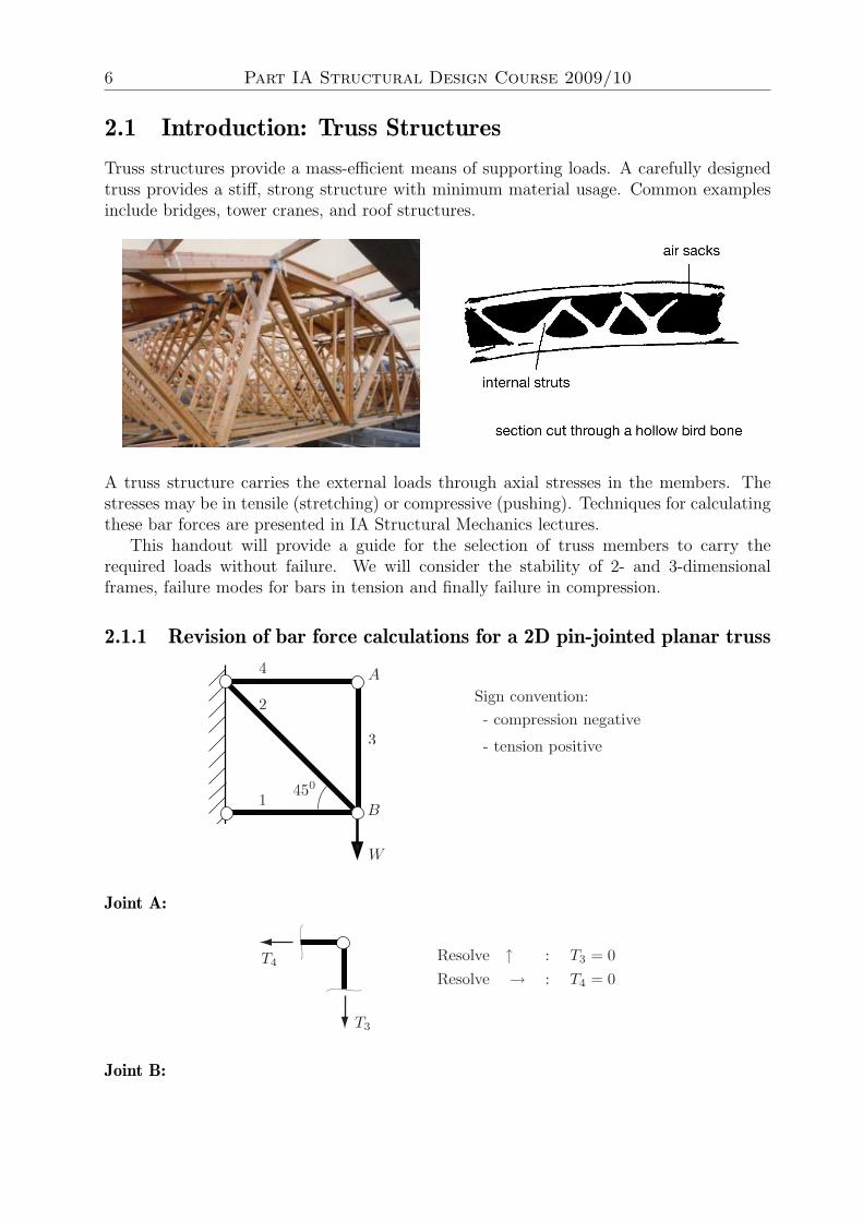
Truss structures provide a mass-efficient means of supporting loads. A carefully designedtruss provides a stiff, strong structure with minimum material usage. Common examplesinclude bridges, tower cranes, and roof structures.
A truss structure carries the external loads through axial stresses in the members. Thestresses may be in tensile (stretching) or compressive (pushing). Techniques for calculatingthese bar forces are presented in IA Structural Mechanics lectures.
This handout will provide a guide for the selection of truss members to carry therequired loads without failure. We will consider the stability of 2- and 3-dimensionalframes, failure modes for bars in tension and finally failure in compression.
2.1.1 Revision of bar force calculations for a 2D pin-jointed planar truss
Joint A:
Joint B:

Handout 2. Member Sizing: Tension and Compression 7
2.2 Stability of the truss
In devising a truss configuration, a triangulated arrangement of bars must connect load tothe supports. Otherwise, the structure can fail as a mechanism under small loads:
shortens
lengthens
The distance between the corner points can freely increase or decrease, if the joints areassumed to behave as pins. Accordingly, the triangulating bar is either in tension or in com-pression, in order to resist these changes in length: tension is preferable since compressivemembers are generally weaker due to buckling - see later.
tension compression
A single, vertical plane structures will normally move out of plane under very small verticalloads. For out-of-plane stability, the structure must be either truly 3-dimensional or two2-dimensional planes connected together, For the latter, two aspects must be considered
1. The two planar trusses should be joined by perpendicular bars or ties at the cornerpoints.
2. All planes on the outside of the new structure, which are potentially mechanisms,need to be triangulated using bracing.

8 Part IA Structural Design Course 2009/10
bracing
tie/spreader bar
The bracing is so-called because it carries no load, theoretically, since there is no componentof load acting within each plane of triangulation. The loading plate (the point of applicationof the external load) may also tie the planes together.
2.3 Failure of bars in tension
The strength of a bar in tension is dependent on the material behaviour. The stress versusstrain for a ductile material such as mild steel in tension is as follows:
ACTUALlimit
elastic
IDEALISED
σσ
εε
σy
If the bar stresses exceed the elastic limit, i.e. experiences yielding, further stress incre-ments can result in large increments in strain. The behaviour is simplified by means of anidealised form (elastically-ideally plastic), with a distinct yield stress, σY
σy = 255N
mm2
If the stress is uniformly carried over the cross-section, then its required cross-sectionalarea to avoid failure is
A >bar force
σy
In practice, end effects arise from the presence of a hole for connecting members by rivetsor bolds. In the detailed computer simulation below, regions of practically zero stress aredark, and vice versa. Note also the high stresses behind the load at the hole.

Handout 2. Member Sizing: Tension and Compression 9
SECTION POINT 1
MISES VALUE+4.60E-01
+3.26E+03
+6.51E+03
+9.77E+03
+1.30E+04
+1.63E+04
+1.95E+04
+2.28E+04
+2.60E+04
+2.93E+04
+3.26E+04
+3.58E+04
+3.91E+04
+4.23E+04
KAS/2001FIXED
LOAD
A smaller cross-sectional area is available near the hole to carry the bar force; consequently,the stresses here must locally increase, and this is therefore the most critical part undertension. The following effective area is therefore used:
effective area
b
b
tD
b2
For b >> t:
Aeff =
2bt︸︷︷︸total
− Dt︸︷︷︸hole
− bt
2︸︷︷︸ineffective
We therefore require:
actual stress =bar force
Aeff
< σy
2.4 Failure of bars in compression
If the member is very short and stocky, it fails by yielding when the stress in the barreaches σy. Otherwise, for slender bars, it fails by buckling, a geometric effect. The criticalbuckling force depends on:
1. The full cross-sectional area (end effects are not crucial)
2. The longest unsupported length between a pair of joints or connected points in a givenmember
10 Part IA Structural Design Course 2009/10
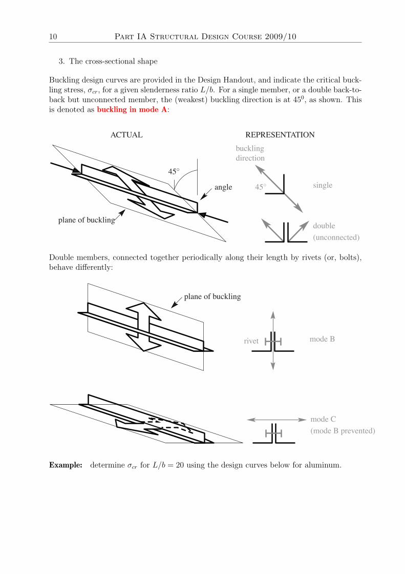
3. The cross-sectional shape
Buckling design curves are provided in the Design Handout, and indicate the critical buck-ling stress, σcr, for a given slenderness ratio L/b. For a single member, or a double back-to-back but unconnected member, the (weakest) buckling direction is at 450, as shown. Thisis denoted as buckling in mode A:
45◦45◦
bucklingdirection
single
double(unconnected)
NOITATNESERPERLAUTCA
plane of buckling
angle
Double members, connected together periodically along their length by rivets (or, bolts),behave differently:
mode Brivet
plane of buckling
mode C(mode B prevented)
Example: determine σcr for L/b = 20 using the design curves below for aluminum.
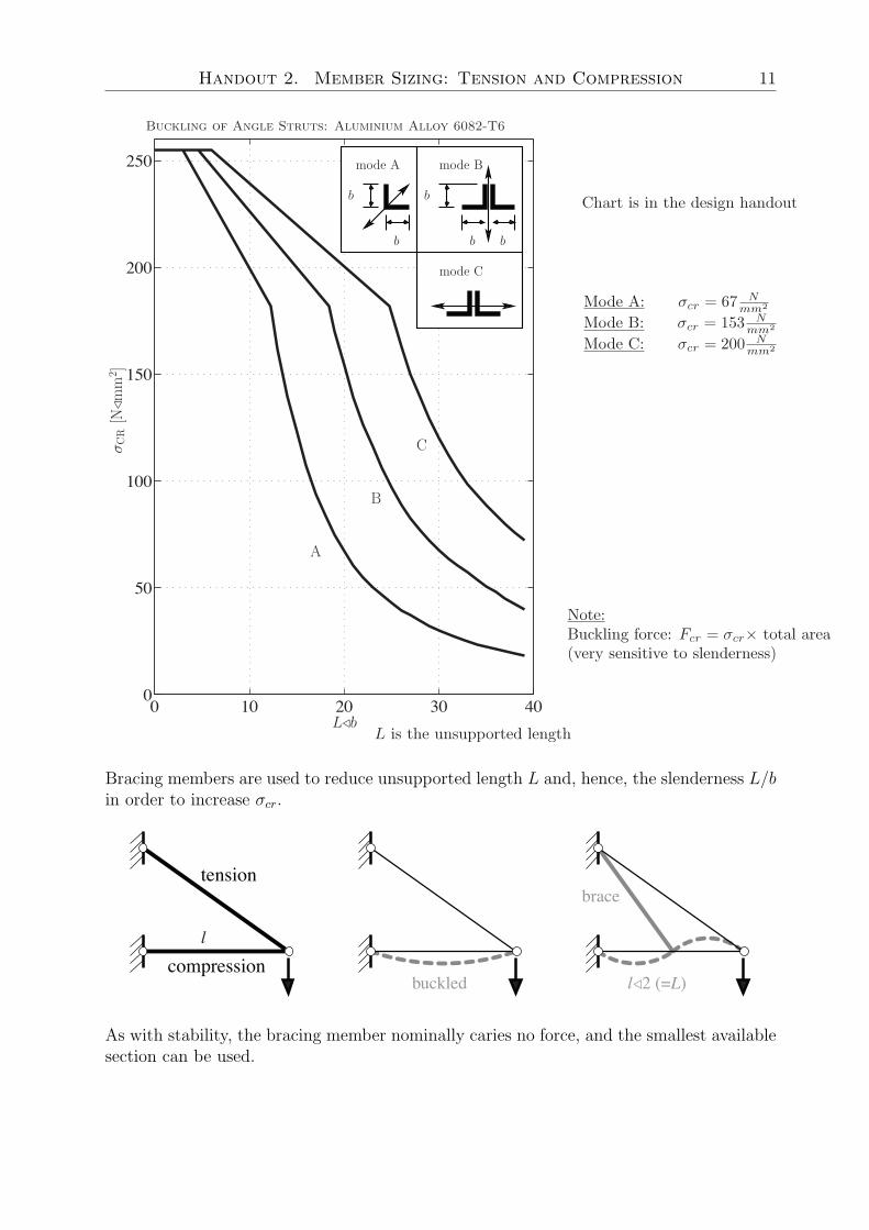
Handout 2. Member Sizing: Tension and Compression 11
Buckling of Angle Struts: Aluminium Alloy 6082-T6
0 10 20 30 400
50
100
150
200
250 mode A mode B
mode C
A
B
C
Lb
σC
R[N
mm
2]
b
b
b
b b
Bracing members are used to reduce unsupported length L and, hence, the slenderness L/bin order to increase σcr.
compression
tension
l
l2 (=L)
brace
buckled
As with stability, the bracing member nominally caries no force, and the smallest availablesection can be used.
12 Part IA Structural Design Course 2009/10
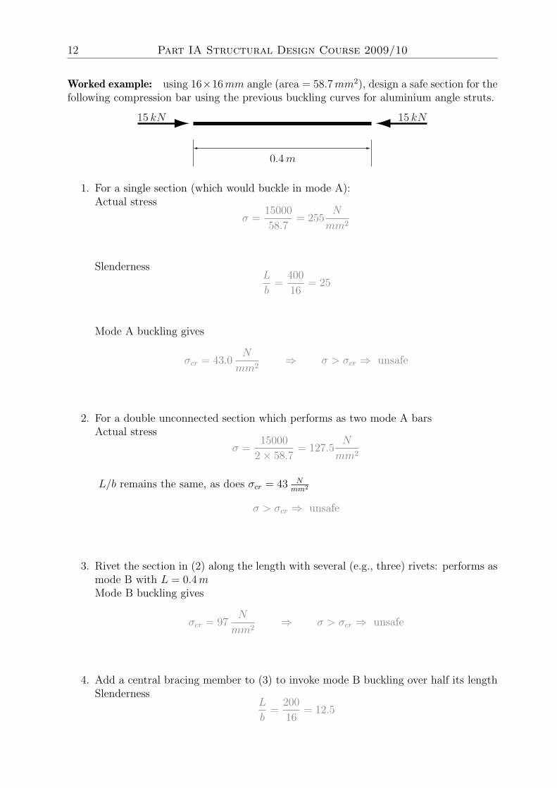
Worked example: using 16×16 mm angle (area = 58.7 mm2), design a safe section for thefollowing compression bar using the previous buckling curves for aluminium angle struts.
1. For a single section (which would buckle in mode A):Actual stress
σ =15000
58.7= 255
N
mm2
SlendernessL
b=
400
16= 25
Mode A buckling gives
σcr = 43.0N
mm2⇒ σ > σcr ⇒ unsafe
2. For a double unconnected section which performs as two mode A barsActual stress
σ =15000
2× 58.7= 127.5
N
mm2
L/b remains the same, as does σcr = 43 Nmm2
σ > σcr ⇒ unsafe
3. Rivet the section in (2) along the length with several (e.g., three) rivets: performs asmode B with L = 0.4 mMode B buckling gives
σcr = 97N
mm2⇒ σ > σcr ⇒ unsafe
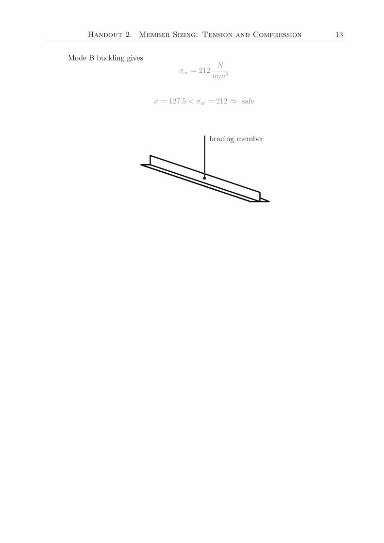
4. Add a central bracing member to (3) to invoke mode B buckling over half its lengthSlenderness
L
b=
200
16= 12.5
Handout 2. Member Sizing: Tension and Compression 13
Mode B buckling gives
σcr = 212N
mm2
σ = 127.5 < σcr = 212 ⇒ safe

14 Part IA Structural Design Course 2009/10
Part IA Structural Design Course 2009/10
Handout 3
Joint Design
Supervisor versionText and pictures in grey are omitted from the student version.
Fehmi Cirak, February 24, 2010

16 Part IA Structural Design Course 2009/10
3.1 Introduction
This handout will provide a guide for joint design and dimensioning. Poorly designedjoints can compromise the load carrying capacity of the entire structure. For example,the I-35W Mississippi River bridge in Minneapolis collapsed on August 1, 2007 because ofunderdimensioned joints. The collapse killed thirteen people and injured 145 people.
3.2 Joints and Load Paths
T
TT
For joint design it is helpful to think about load paths
It is evident that every component on the load path must be capable transmitting load.The weakest component on the load path determines the overall strength. (Strength of achain is determined by its weakest link.)
The line of action is the line along the centroid of a cross-section.
Handout 3. Joint Design 17
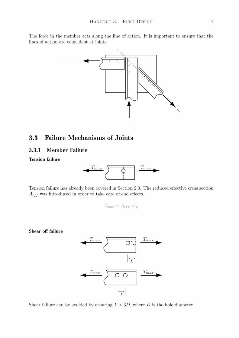
The force in the member acts along the line of action. It is important to ensure that thelines of action are coincident at joints.
3.3 Failure Mechanisms of Joints
3.3.1 Member Failure
Tension failure
Tension failure has already been covered in Section 2.3. The reduced effective cross sectionAeff was introduced in order to take care of end effects.
Tmax = Aeff · σy
Shear off failure
Shear failure can be avoided by ensuring L > 3D, where D is the hole diameter.
18 Part IA Structural Design Course 2009/10
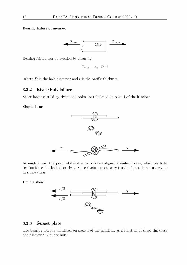
Bearing failure of member
Bearing failure can be avoided by ensuring
Tmax = σy ·D · t
where D is the hole diameter and t is the profile thickness.
3.3.2 Rivet/Bolt failure
Shear forces carried by rivets and bolts are tabulated on page 4 of the handout.
Single shear
In single shear, the joint rotates due to non-axis aligned member forces, which leads totension forces in the bolt or rivet. Since rivets cannot carry tension forces do not use rivetsin single shear.
Double shear
3.3.3 Gusset plate
The bearing force is tabulated on page 4 of the handout, as a function of sheet thicknessand diameter D of the hole.
Handout 3. Joint Design 19
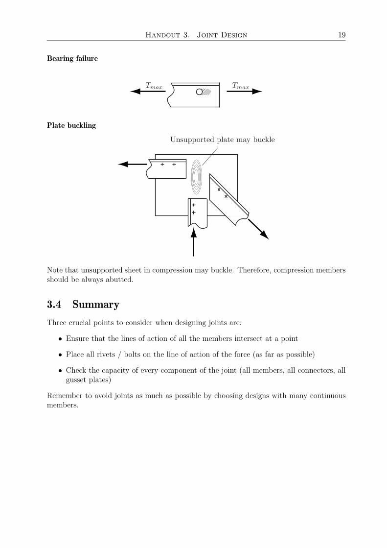
Bearing failure
Plate buckling
Note that unsupported sheet in compression may buckle. Therefore, compression membersshould be always abutted.
3.4 Summary
Three crucial points to consider when designing joints are:
• Ensure that the lines of action of all the members intersect at a point
• Place all rivets / bolts on the line of action of the force (as far as possible)
• Check the capacity of every component of the joint (all members, all connectors, allgusset plates)
Remember to avoid joints as much as possible by choosing designs with many continuousmembers.

20 Part IA Structural Design Course 2009/10

Part IA Structural Design Course 2009/10
Handout 4
Design Drawings and Final Report
Supervisor versionText and pictures in grey are omitted from the student version.
Fehmi Cirak, February 24, 2010

22 Part IA Structural Design Course 2009/10
Detailed Design Drawings
• In pencil, on A3 cartridge paper (provided)
• Do not remove drawing boards or drawing equipment: LR3A may be used weekdayafternoons, DPO at the weekend.
DPO should not be used for structural design during week
• The drawing must contain enough information for someone else to build the structure
– draw to scale
– mark all dimensions explicitly · · ·
– · · · but don’t include redundant information
– use a consistent projection
– include all relevant detail (fastener locations, orientation of angle sections, sizeand shape of gusset plates etc.)
– show as many views as are necessary

Handout 4. Design Drawings and Final Report 23
G roup N o. :N ames:D rawn by:D rawing N o. . . . . of. . . .T itle: G eneral A rrangement J oint D etails 1or
D ate:
S ide E levation
P lan
E nd E levation
D etail A3
S cale: 1 :5
1 1 5
Sample drawing of general arrangement
Sample drawing of a joint detail
24 Part IA Structural Design Course 2009/10
Test Session
Tuesday, 1 December, 11am –1pm, Structures Teaching Lab
1. Bridges are tested to destruction, most expensive first
2. Test milestones:
(a) does it fit the test rig?
(b) does it reach the working load without noticeable deformation?
(c) does it reach the failure load (= 2× working load)?
(d) actual failure load?
3. Group presentation shared by both members:
• explain the merits of the design
• describe possible failure modes
• identify the critical failure mode
4. You may want to take photos before and after testing
Handout 4. Design Drawings and Final Report 25
Final Report
1. Write the report at the opposite end of the lab book to your design notes
2. Text only may be word-processed and pasted in
3. Sketches, calculations and equations must be hand written
4. Include the following information (listed in Design Handout)
• summary (about 100 words)
• problem statement
• summary of the design process, including sketches
• detailed hand calculations for the final design
• costing sheet (completed after construction)
• differences: design versus as-built
• discussion on the test
• suggested improvements
• conclusions
5. Feedback session at the end of term