handouts - presentation slides, regulatory issue ... · greg oberson, materials engineer, res/de...
TRANSCRIPT
Regulatory Issue Resolution Protocol (RIRP) Pilot:
Marine Atmosphere Stress Corrosion Cracking (SCC)
Sara DePaula, Materials Engineer, NMSS/SFST
Greg Oberson, Materials Engineer, RES/DE
April 12, 2012

Overview
RIRP Background
Regulatory Background
Technical Information
Path Forward
2

RIRP BACKGROUND
3

RIRP Background
Identified by the NRC Austenitic stainless steel (SS) is susceptible to SCC
in chloride environments, near salt water bodies
Insufficient data available to determine extent of spent fuel storage canisters susceptibility to SCC Specific environmental conditions
Associated time scales
NUREG-7030 demonstrated SCC for relevant environments
4
Screening and Planning Phases February 2010: Initial proposal
March 2011: Drafted problem and success criteria
February 2012: Discussed progress
Need to update schedule, considering parallel efforts
Implementation Phase (Ongoing) Research existing data (complete)
Field Testing
Develop Screening Criteria
Closure Phase (Pending) 5
RIRP Background

REGULATORY BACKGROUND
6

Deployed Canisters
7
U.S. CANISTER DESIGN TECHNOLOGIES
BFS/ES 66
GNB 26
Holtec 446
NAC 269
Transnuclear 603
TOTAL 1410
Source: Compiled from StoreFuel, Vol. 13, Num. 164, April 3, 2012

Example Canister Designs
8

NRC Regulatory Focus
Initial License Terms (0-20 years) No immediate safety issue identified
NRC continues to monitor and evaluate data; expects same from licensees
Unexpected, premature weathering damage of other cask components has been detected and mitigated
Renewal Terms (20-60 years) Renewal terms may be more conducive to initiation of undetected
SCC
SRP-LR for reactors recommends external surface monitoring of stainless steel in chloride environments
Extended Storage (60+ years) Addressed through NRC EST and EPRI ESCP
9
Reference: NUREG-1800; NUREG-1801

Governing Regulations Confinement Integrity
Designed to accommodate environmental conditions
No significant chemical, galvanic, or other reactions
Inspected to ensure no defects
Maintain confinement (normal, off-normal, and accident conditions)
Periodic monitoring to determine when corrective action is needed
Dose Limits Confinement features must be sufficient to meet 10 CFR 72.104,
106
Ready-Retrieval Cladding must be protected such that degradation will not pose
operational safety problems upon removal
Storage systems must be designed to allow ready retrieval
10
Source: 10 CFR 72.24(l)(1); 72.120(d); 72.122(b),(h)(1),(h)(4),(l); 72.236(d),(j),(l)
Note: List is not comprehensive; most pertinent governing regulations are noted.

Governing Regulations
License renewal Assessment based on initial licensing basis
AMP describes management of issues associated with aging that could adversely affect SSCs important to safety Prevention
Mitigation
Condition Monitoring
Performance Monitoring
Demonstrate SSCs important to safety have not been adversely affected
11
Source: 10 CFR 72.3, 72.42(a)(2), 72.240(c)(3),(d)
Loss of confinement integrity Potential radiological exposure
Loss of helium and radionuclides
Oxidation of fuel cladding
Additional concern during retrieval and transfer of fuel
Environmental contamination
Failure times and likelihoods are unknown No monitoring of canister integrity
Relevant examples of chloride-induced SCC in austenitic SS are known
Further assessment of canisters is needed
12
Safety Issues

Safety Assessment
Industry should assess the significance for specific site locations and cask designs Prioritize based on potential vulnerabilities
Consider current license terms and future renewals
Provide to NRC for evaluation under appropriate process
Consider significant parameters Canister surface temperature
Local humidity
Salt concentration and composition
Stress state of canister
Exposure times
13

Aging Management
Welded canisters are not typically monitored and not readily accessible when in storage
Industry should consider aging management approaches to assess phenomena Performing corrosion analyses
Collecting data
Establishing preventative maintenance activities
Monitoring and inspecting canisters
Mitigating potential corrosion damage
14

TECHNICAL INFORMATION
15

Technical Information – Key Messages Available operational experience (OpE) indicates events where SCC of
austenitic SS components was attributed to atmospheric chloride exposure.
The susceptibility for SCC appears to increase at lower temperatures, potentially less than 60 to 80oC.
The DRH for sea salt appears close to that of MgCl2. SCC on U-bend specimens with sea salt is observed at RH less than the DRH for NaCl and at AH less than 30 g/m3.
SCC is observed on U-bend specimens covered with 1 g/m2 of sea salt at AH less than 30 g/m3.
Visual examination has not been demonstrated to identify the features associated with SCC of the canister.
More information is needed concerning the actual conditions of canisters in the field.
16

OpE Overview
SCC of austenitic SS components attributed to atmospheric chloride exposure Nuclear Power Plant Events
Other industrial and commercial components
Events provide some indication of potential susceptibility of canisters to SCC
17

Examples of Plant OpE
St. Lucie Unit 2 – April, 19991
Leaking of 304 SS piping in refueling water storage tank (RWST) trench exposed to atmosphere
~16 years in service (Unit 2 commissioned 1983)
Branched through-wall cracking initiated on pipe OD
24” diameter, ¼” wall piping, 30 psig at 120°F (49°C)
Indications more severe at field welds
Turkey Point Unit 3 – April, 20052
Flaw in 304 SS spent fuel pool cooling line attributed to chloride-induced SCC
Initiated on pipe OD, at base of a pit
Piping housed in room with grating steel door open to outside
Indication ½” from flange butt weld, in HAZ
18
1. LER 389-1999-003: “ECCS Suction Header Leaks Result in Both ECCS Trains Inoperable and TS 3.0.3 Entry,” ADAMS Legacy Library Accession Number 9905130085.
2. L-2005-168: “10 CFR 50.55a Request for Temporary Non-Code Repair,” ADAMS Main Library Accession Number ML052780060.

Examples of Plant OpE
Ohi Unit 1 (Japan) – July, 20043
Cracking in the SS RWST exposed to outdoor environment (5 locations)
Crack noted in the vicinity of backplate weld
Tank was installed without coating in 1974; coated in 1981
~30 years in-service
19 3. Japan NISA/METI News Release PRI-04-25, “Report and Its Examination Result from Kansai Electric Power Company on Cause and Countermeasures of Defect (Water Ooze from Refueling Water Storage Tank) Found During the Periodical Inspection of Ohi Power Station Unit-1, Kansai Electric Power Company,” July 27, 2004.
Examples of Plant OpE
Koeberg Units 1 and 2 (South Africa)
Cracking in 304L piping connected to tank exposed to outdoor environment4 Extensive crack networks initiating from surface pits
Cracks in 304L PTR tanks5 Primarily in areas adjacent to welds
Fabricated to ASME Code, Section III, Subsection NC
Water maintained between 7 and 40°C
<30 years in-service
20
4. M. van Dalen, C. Wicker, G. Wilson, “Non Destructive Testing of Materials Subject to Atmospheric Stress Corrosion Cracking,” 17th World Conference on Nondestructive Testing, Shanghai, China, 2008.
5. RFI No. NUC110801/WB, Appendix 6.1, Ref. DSG-310-301, “Technical Specification for Replacement PTR Tanks for Koeberg Nuclear Power Station,” 2001. http://mp2mas17.eskom.co.za/tenderbulletin/details.asp?id=936

Other Industrial and Commercial OpE Stainless steel nuts for atmospheric test racks
at Kure Beach6
304L Dished ends for outdoor pressure vessels7,8
316L Rock climbing hangers in seaside cliffs9
21
6. R. Kain, “Marine Atmospheric Stress Corrosion Cracking of Austenitic Stainless Steels,” Materials Selection and Design, December 1990.
7. J.B. Gnanamoorthy, “Stress Corrosion Cracking of Unsensitized Stainless Steels in Ambient-Temperature Coastal Atmosphere,” Materials Selection and Design, December 1990.
8. R. Dayal, J. Gnanamoorthy, ”Failure of a Stainless Steel Tank Used for Storage of Heavy Water/Helium,” Handbook of Case Histories in Failure Analysis, Vol. 2, K.A. Esakul, Ed., ASM International, 1992.
9. A. Sjong, L. Eiselstein, “Marine Atmospheric SCC of Unsensitized Stainless Steel Rock Climbing Protection,” Journal of Failure Analysis and Prevention, Volume 8, pages 410-418, 2008.
Considerations for Assessing SCC Susceptibility Deposition rate of salt on canister surface
Deliquescence temperature and humidity
Minimum salt concentration for SCC
Tensile stresses
22

NRC Sponsored Research at SwRI/CNWRA Previous and current NRC-sponsored work primarily focused on
defining: Temperature and humidity requirements
Minimum salt concentration for SCC
NUREG/CR-7030 work10
Salt spray and salt fog testing of U-bend specimens
Limited control of salt deposition
High absolute humidity conditions
Ongoing EST research program11
Initiated in support of extended storage and transportation activities
Cyclic or static exposure of U-bend specimens
Known quantities of salt deposited on specimens
23
10. NUREG/CR-7030, “Atmospheric Stress Corrosion Cracking Susceptibility of Welded and Unwelded 304, 304L, and 316L Austenitic Stainless Steels Commonly Used for Dry Cask Storage Containers Exposed to Marine Environments, 2010.
11. T. Mintz, L. Caseres, X. He, J. Dante, G. Oberson, D. Dunn, T. Ahn, “Atmospheric Salt Fog Testing to Evaluate Chloride-Induced Stress Corrosion Cracking of Type 204 Stainless Steel,” CORROSION 2012, Salt Lake City, ADAMS Main Library Accession Number ML120720549.

NUREG/CR-7030 – Key Findings For salt fog tests conducted at 43, 85, and 120°C,
only U-bend specimens at 43°C exhibited SCC – 304, 304L, and 316L
At 43°C, 304, 304L, the extent of cracking increased with time from 4 to 52 weeks exposure.
At 43°C, 316L, cracking detected at 32 weeks
24

NUREG/CR-7030 Test Conditions
High absolute humidity (AH) ~ 60 g/m3
AH limit in nature ~ 30 g/m3
At 43°C, relative humidity (RH) above deliquescence RH (DRH) for NaCl
No tests between DRH for MgCl2 and NaCl
Possibility of liquid water contacting specimens from test methodology rather than deliquescence
25

Ongoing EST Research Program Determine minimum salt concentration for crack initiation
Deposit known quantities of ASTM sea salt onto type 304 U-bend specimens; as-received, sensitized, and welded
Expose specimens at temperatures of 35 and 45°C to cyclic humidity up to AH of 30 g/m3
Specimens coated with 0.1, 1, or 10 g/m2 salt 26
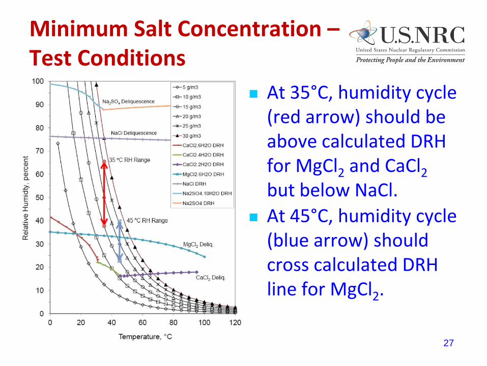
Minimum Salt Concentration – Test Conditions
At 35°C, humidity cycle (red arrow) should be above calculated DRH for MgCl2 and CaCl2 but below NaCl.
At 45°C, humidity cycle (blue arrow) should cross calculated DRH line for MgCl2.
27

Minimum Salt Concentration Preliminary Observations Within 3 months, as-received and sensitized specimens with 1 or 10 g/m2
salt showed intergranular cracking. No welded specimens have cracked yet, but there may be interdendritic attack.
Some specimens with 0.1 g/m2 salt at 35°C have minor pitting.
Preliminary results are consistent with Japanese reports on threshold chloride ion concentration for SCC of 0.8 g/m2.12,13
28
12. K. Shirai, J. Tani, H. Takeda, M. Wataru, T. Saegusa, “SCC Evaluation of Test Multi-Purpose Canister,” 2011 Water Reactor Fuel Performance Meeting, Chengdu, China, September 11-14, 2011.
13. T. Saegusa, “Issues and Countermeasures for Long-Term Storage of Spent Fuel by Dry Cask,” 2012 NRC Regulatory Information Conference.

Ongoing EST Research Program – Elevated Temperature Deliquescence and SCC
Determine DRH for sea salt and its pure salt constituents at temperatures in the range of 45 to 80°C.
Measure DRH by observing salts in beakers at different humidity levels or other analytical methods such as the conductivity cell.
Expose U-bend specimens to range of humidity levels at the elevated temperatures to determine conditions where SCC could occur.
29

Elevated Temperature Deliquescence Preliminary Observations
For conductivity cell measurements, deliquescence creates conductive electrolyte reducing the measured impedance.
30
DRH for CaCl2 is lowest of sea salt constituents, in the range of 20 to 25% RH.
DRH is similar for MgCl2 and sea salt, in the range of 30 to 35% RH.
Deliquescence of NaCl is not observed up to 50% RH.
Efflorescence may not occur until lower humidity than DRH.
45oC 80oC

Elevated Temperature SCC Test Plan
Expose U-bend specimens coated with 10 g/m2 salt at temperatures of 60 and 80°C and constant RH.
Start with relatively high RH of 40%, above DRH for MgCl2.
If cracking occurs, expose new specimens at progressively lower RH to observe trend for crack initiation.
Japanese data showed SCC at 80°C and 16% RH for CaCl2.14
31 14. M. Mayuzumi, J. Tani, T. Arai, “Chloride induced stress corrosion cracking of candidate canister materials for dry
storage of spent fuel,” Nuclear Engineering and Design, Volume 283, pages 1227-1232, 2008.

Elevated Temperature SCC Preliminary Observations Cracking observed for specimens tested at 60°C and 40% RH.
Testing underway at 35% RH, should be near or slightly above MgCl2 and sea salt DRH.
Testing underway at 80°C and 40% RH, and appears that cracking has occurred. Test is well above expected DRH for MgCl2 and sea salt. Subsequent tests planned at lower RH.
32
Specimens tested at 60oC and 40% RH.

Considerations for Future NRC-EST Research Dilution of chlorides at high RH15,16
Effects of stress and strain level on crack initiation Alternatives to U-bend testing, including C-ring, bent beam, notched tensile, or others
Japanese data showed SCC at half of the yield stress14
Non-coastal atmospheric species or industrial pollutants (underway)
Welding residual stress analyses Potential for tensile stresses to propagate through wall
May consider lid and body welds
Non-destructive examination methodologies There is no currently qualified technique or acceptance criteria for examination of the
canisters.
Challenges for remote visual examination include accessibility, camera resolution, lighting, and surface condition among others.
The ability of remote visual examination to identify features associated with SCC has not been shown by performance demonstration, mockup testing, or other means.
33
14. M. Mayuzumi, J. Tani, T. Arai, “Chloride induced stress corrosion cracking of candidate canister materials for dry storage of spent fuel,” Nuclear Engineering and Design, Volume 283, pages 1227-1232, 2008.
15. O.E. Albores-Silva, E.A. Charles, C. Padovani, “Effect of chloride deposition on stress corrosion cracking of 316L stainless steel used for intermediate level radioactive waste containers,” Corrosion Engineering, Science, and Technology, Volume 46, pages 124-128, 2011.
16. J. Prosek, A. Iversen, C. Taxén, D. Thierry, “Low-temperature stress corrosion cracking of stainless steels in the atmosphere in the presence of chloride deposits,” Corrosion, Volume 65, pages 105-117, 2009.

Preliminary Weld Residual Stress Analysis High tensile stresses in hoop
direction
Estimated parameters – configuration, heat input, number of passes, etc.
Potential cracks would tend to orient radially
34
Hoop stress distribution, MPa
-200
-100
0
100
200
300
400
500
600
0 2 4 6 8 10 12 14 16 18
Stre
ss,
MP
a
Distance from weld top, mm
Weld bottom Weld top
High tensile hoop stress at top of weld subject to corrosive environment
Hoop Stress
Axial Stress

Current Information Needs
Additional information from industry is needed to reduce the uncertainty concerning the potential for SCC of the canisters.
Actual conditions of canisters in field Temperature – Actual heat load, measured surface temperature
Humidity
Salt concentration in air Japanese measured salt concentration in air at Tokai and Fukushima13,14
Similar concentration in dry storage building as outside
Amount and composition of salt on canister surface
Welding design and parameters for lid and body welds Joint design
Welding technique and parameters
Repairs
35
13. T. Saegusa, “Issues and Countermeasures for Long-Term Storage of Spent Fuel by Dry Cask,” 2012 NRC Regulatory Information Conference.
14. M. Mayuzumi, J. Tani, T. Arai, “Chloride induced stress corrosion cracking of candidate canister materials for dry storage of spent fuel,” Nuclear Engineering and Design, Volume 283, pages 1227-1232, 2008.

PATH FORWARD
36
Summary
RIRP Problem Statement (08/2011): There is insufficient data to determine the environmental conditions, and associated time scales, necessary for potential initiation of chloride-induced stress corrosion cracking (SCC) in stainless steel dry spent nuclear fuel (SNF) storage canisters deployed at ISFSI locations.
RIRP participants should discuss whether process is working adequately for this issue
37 Reference: NRC letter to NEI, “Nuclear Regulatory Commission Response to Industry Regarding Coastal Marine Atmosphere Issue,” dated August 4, 2011, ADAMS Accession Number ML1121700692.

Alternative Processes
NRC continues to consider other regulatory processes beyond RIRP Generic Communications
RIS
Information Notice
Generic Letter
Industry programs beyond ESCP
38