handpunch 3000/4000 installation manualtkb.amano.com/phpkb/assets/hp_34000_inst_5.pdfhandpunch...
TRANSCRIPT

HandPunch 3000/4000Installation Manual
Recognition Systems Inc.1520 Dell Ave.Campbell, CA 95008
Tel 408-364-6960Fax 408-370-3679Email: [email protected]

HandPunch 3000/4000 Installation Manual
Revision 1.01 1
Table of contents
HandPunch technology overview 2
Installation planning 3
Wiring overview 4
Mechanical installation 5
Power and network wiring 6
Command mode and setup 8
Power up 9
Command mode 10
Setup menus 11
Connecting to a network, Memory reset, Enrollment overview 15
Host computer to network wiring diagram 16
Modem/Network diagram 17
Terminal strip and connector locations 18
Lock, bell and auxiliary output wiring 19
Lock, bell and auxiliary wiring diagram 20
External magnetic stripe wiring diagram 21
Communications wiring locations 22
Specifications 23
Warranty 24
Index 26

HandPunch 3000/4000 Installation Manual
Revision 1.012
HandPunch TechnologyThe HandPunch uses the size and the shape of the human hand to verify a person’s identity.It does not read fingerprints or the palm. To use the system, the enrolled user enters an IDnumber via a keypad, or by presentation of a card. The system prompts for the hand to beplaced on the measuring surface, and once the hand is in place, it records the shape the handin three dimensions with a CCD (chip) camera. A microprocessor extracts over ninetymeasurements and compares them to a previously stored template. Upon successful IDverification, the terminal records the time, date, user ID number and collected time andattendance data for collection by a host computer. Depending on the setup, the HandPunchterminal can also unlock a door or send card data to an access control system.
HandPunch General DescriptionThe HandPunch 3000 and 4000 are the latest in Recognition Systems' line of Hand GeometryTime and Attendance Terminals. The HandPunch provides proof-positive employeeidentification combined with the sophisticated operating features one expects in a modernTime and Attendance Terminal. Because of this unique combination of capabilities, theHandPunch provides the most accurate Time and Attendance data collection terminalavailable. Important features of the HandPunch are:
Two Data Management KeysUser Time RestrictionsSupervisor Override at the Clock
Add PunchAdd Bulk Hours-or DollarsReview Punches
Department TransfersExplicit Punch MenuTransaction Buffer (FIFO) 5,187 event capacity HP3000, 8190 capacity HP-4000.ID Number Input
Keypad or external card reader, HP-3000 & 4000. Integral card reader HP-4000.Bell SchedulesDoor Controls and monitoringProgrammable Daylight Savings SwitchoverProgrammable Clock and Date Formats

HandPunch 3000/4000 Installation Manual
Revision 1.01 3
Installation:
Installation is a seven step process:• Determine where each HandPunch reader terminal will be installed.• Install the wall plate.• Install wiring within the walls of the facility.• Mount the HandPunch terminal to the wall plate.• Connect power and communications wiring.• Set communication parameters at the HandPunch terminal.• Connect the computer to the network.
Hand reader placementThe reader should be in a convenient location near the employee entrance where it is notexposed to water, chemicals, or direct sunlight. The platen should be 40 inches (102 cm)from the floor.

HandPunch 3000/4000 Installation Manual
Revision 1.014
Wiring overview:
Power: A 120VAC duplex outlet should be within 5 feet of the hand reader. The suppliedRSI plug-in power supply has a 6 feet (182 cm) long cable.
Communications: Each direct connect HandPunch unit requires a network jack. AHandPunch with internal modem requires telephone jack. A modem unit connected toadditional HandPunch terminals requires both a network connection and a telephone jackThese RJ-11 jacks are to be installed on or in the wall behind the reader. Locate the wiringand jack locations using the paper template included with this manual. Each HandPunchterminal comes with a short silver cable to connect the terminal to the network jack. Modemunits include a black modem cable to connect the terminal to a telephone jack.
The network requires two twisted pairs, 22 AWG. minimum. It connects between networkjacks installed at each reader “daisy-chain” fashion. Belden No. 82723 cable isrecommended. Do not wire HandPunch terminals in a “star” network.
When the HandPunch terminals are directly connected to the computer, communication is viaa shielded 4 wire (Full Duplex) RS-485 multidrop configuration. This data link may extendup to 4,000 feet, and up to 31 hand readers can be connected to it in addition to the host.
When a modem is used, up to 30 HandPunch terminals can be connected to it. Theinterconnection between the modem unit and the other HandPunch terminals is via shielded 4wire (Full Duplex) RS-485 multidrop configuration. The total cable distance can not exceed4000 feet in length.
At the Host computer: A network jack must be installed within 6 feet (182 cm) of the hostcomputer. The network jack is a standard RJ-11 type of the same kind used in standardtelephone installations. A data converter (RSI No. DC-101P) is required to communicate withRS 485 networked hand readers. On side of the DC-101P is plugged into the RS 232 serialcommunication port on the computer. The other side is connected to a network jack via thesupplied cable The DC-101P comes with an eight foot (182 cm) cable with RJ-11 plugs oneach end.

HandPunch 3000/4000 Installation Manual
Revision 1.01 5
Mounting the Wall Plate
Remove the wall plate from the packing carton.Protect the hand reader terminal from dust and debrisduring the wall plate installation.• Measure and mark a point 48-1/2 in. (123 cm.) tothe finished floor.• For hollow walls, drive a small nail into the wall atthe mark and hang the wall plate from the hole locatednear the top. Check to assure the wall plate is level.Secure it with tape if necessary• For solid walls, place the hole at the mark, level thewall plate and secure the plate with tape.• Using the wall plate as a template, mark thelocations of the two holes near the top and three holesat the bottom.• Remove the wall plate from the wall and install the
mounting hardware
Mounting HardwareHollow walls:Use the provided hardware to mount the wall plate.The auger style fasteners are for the two uppermounting locations. The molly bolts are for the threelower mounting locations. Drill a ¼” hole at each ofthe lower locations and install the molly bolts.Completely remove the screws from each of the mollybolts and set aside. Install the auger fasteners into theupper locations (do not install the screws)
Concrete walls:Expansion bolts should be used for concrete walls.Drill ¼ in. diameter hole ¼ in deeper than the anchorlength for all five mounting holes and insert anchors.
Note: For surface conduit installations, prepare twoadditional holes for the conduit clamp and insertanchors.
Place the wall plate on the wall and screw into place.

HandPunch 3000/4000 Installation Manual
Revision 1.016
Wiring and network jack locations
Wiring for the terminal may be brought to it throughthe open area in the center of the wall plate for hollowwalls or through the conduit opening on the right sideof the terminal. See drawing on page 22.
Network wiringFor network wiring, an RJ 11 is required at each unit.A short cable supplied with the unit makes the finalconnection from the jack to the terminal. A wall platetype RJ 11 jack is recommended for hollow walls, buta surface wall jack can also be used. The surfacemount type must be used for solid wall applications.Positioning of the surface mount jack is critical so thatit will not interfere with locking the terminal intoplace. Use the pictures to the left to locate the jack.
Network wiring between the jacks must be completedin accordance with the appropriate network wiringdiagram in the back of this manual. Network wiringmust be in a “daisy chain” fashion only. Do not wirein a “Star” configuration.
The diagram on page 16 is for a hard-wiredconnection to the host computer. The diagram onpage 17 is for a network using a modem forconnection to the host computer.
In multiple unit networks, mark the jack of the lastterminal on the network “EOL” for end of line. Theterminal at the end of the line requires the setting ofdip switches to terminate the network.
PowerRoute the power cable from the RSI power supply tothe HandPunch terminal through the open area in thecenter of the wall plate for concealed wiring orthrough the conduit opening on the right side forsurface wiring. The duplex wall outlet to plug thepower supply into should not be further away than 5feet from the terminal. If located further than 5 feet,you can use an alternative power supply or wiringattached to a connector (provided). 18 AWG wire isrecommended for this situation.

HandPunch 3000/4000 Installation Manual
Revision 1.01 7
Additional Wiring
HandPunch can control external devices:
BellDoor LockRequest for Exit SwitchDoor SwitchAuxiliary DevicesPrinter
Wiring for these devices should enter the reader through the opening in the center of the wallplate or through conduit opening at the right side of the terminal. See the descriptions andwiring diagram on pages 19 and 20.
Conduit WiringThe use of conduit is suggested to protect wiring on solid wall applications. The terminalaccepts ½’ FLEXIBLE conduit. Solid conduit should not be used to enter the terminal.
Route ½ in. conduit to stop between the two conduit clamp holes. A conduit clamp (notsupplied) will hold the conduit in place. All wiring should be routed through the conduit.Power connection to the terminal can be made via stripped and tinned wiring. 18 AWG wireis recommended for this situation.
For all but the network wiring, plan on an additional 18 inches of wire to extend beyondthe end of the conduit to allow for the final connection to the terminal. Network wiring willterminate into an RJ 11 surface wall mount jack located as previously described.
Mounting the unit to the wall• Loosen the three bottom mounting screws soabout ¼ inch of the threads are showing. Remove theterminal from the carton and hang it on the threescrews at the bottom of the wall plate. Tighten allscrews. Protect the terminal from debris and damagewhile completing the installation.
Wiring ConnectionsNetwork connectionsUsing the supplied silver RJ 11 cable, connect oneend into the network jack and the other end into thenetwork RJ 11 jack at the back of the terminal.For modem units, connect the black RJ 11 cable tothe telephone jack and the other to the modem jack atthe back of the unit.
Power connection

HandPunch 3000/4000 Installation Manual
Revision 1.018
Ensure that the power supply is NOT plugged into a power source before making the powerconnection at the terminal. Plug the barrel connector from the power supply into the powerconnection jack at the back of the terminalNote: If using stripped and tinned wire connections, connect the power wiring into the grayterminal strip located directly in front of the barrel connector at the back of the reader.Polarity is unimportant.
Other wiring connectionsMake final wiring connections per the instructions that follow this section. Refer to the chartbelow for terminal strip and jack locations. Typical systems wiring diagrams are located inthe back of this manual.
Setting the dip switches for the EOL (end ofline) terminal.
In a networked system, the dip switches shouldbe set for proper network communications. Thelast reader in the network should have a jackmarked EOL for the “end of the line”. Set dipswitches 1 AND 2 on the unit at the end of theline to the ON position. Dip switch 3 shouldalways be in the OFF position.
Dip switch settings on modem units:Set dip switches 1 and 2 on modem units to “ON.”

HandPunch 3000/4000 Installation Manual
Revision 1.01 9
Power upThe terminal is ready to be powered up. It is bestto apply power before locking the reader in itsnormal operating position.
Plug the power supply into its duplex outlet.After a few seconds, the LCD will display
ENTER ID(TIME) (DATE)
Swing the terminal upward and lock in place withthe key provided.
If the display does not show ENTER ID, recheckyour power connections.

HandPunch 3000/4000 Installation Manual
Revision 1.0110
Hand reader setupCommand Mode OverviewThe Command Mode is broken down into five different groups of commands. Access to eachgroup is controlled by an individual password. The commands contained in each of thegroups are shown in the chart below.
COMMAND MODE STRUCTURE
SPECIAL
DEFAULTPASSWORD 5
ENROLLMENT
DEFAULTPASSWORD 4
MANAGEMENT
DEFAULTPASSWORD 3
SETUP
DEFAULTPASSWORD 2
SERVICE
DEFAULTPASSWORD 1
SPECIAL ENROLL ADD EMPLOYEE SUP OVERRIDE(REVIEW, ADD PUNCH,BULK OR DOLLARS)
SET LANGUAGE CALIBRATE
ADD SUPERVISOR LIST EMPLOYEES SET DATE FORMAT STATUS DISPLAY
REMOVE EMPLOYEE SET EMPLOYEE DATA SET TIME & DATE
RESTRICTIONS SET ADDRESS
SET ID LENGTH
SET SERIAL
This table depicts the structure of all of the commands which are available in the HandPunch.This section of the manual will describe those commands to set up and use the hand reader.The numbers directly above each of the command groups are the factory set passwords toaccess each group.
PasswordsWhen the unit is shipped from the factory, the passwords are all set according to the tablebelow. Access to the various Command Mode commands is controlled by passwords. Eachcommand group has a password as shown in the chart below. Once a system has beeninstalled, you can change the passwords from the host computer. Assigning groups the samepassword allows access to two or more groups. The passwords can be up to10 digits inlength.
SPECIAL GROUP 5 ENROLLMENT GROUP 4 MANAGEMENT GROUP 3 SETUP GROUP 2 SERVICE GROUP 1

HandPunch 3000/4000 Installation Manual
Revision 1.01 11
Entering and Exiting the Command ModeIf no users are enrolled on the system, press CLEAR and ENTER at the same time. TheLCD will display ENTER PASSWORD. If there are enrolled users, the LCD panel willdisplay ENTER ID *:. You must enter your ID followed by # and verify identity by placingyour hand on the platen. When the LCD panel displays ENTER PASSWORD, press thenumerical password of the command group you want to access followed by #. If the displayreturns to ENTER ID, you are not authorized to enter the command mode. If you still cannotenter the command group, it may be necessary to erase the user memory by opening thereader with a key and reset the memory with the internal dip switches as shown on page 9.Once the Command Mode has been entered, the display will show one command at a time inthe top line. Shown in the second line will be the prompt:
* NO YES #
Pressing the # (yes) key will select the displayed command. Prompts will then appear asappropriate for the selected command.
Pressing the * (no) key will cause the next command in turn to be displayed. Repeatedlypressing the * key will bring the display back to the first displayed command.
When the *NO YES# prompt is shown on the display, pressing any number will exit theCommand Mode and return control to the Identity Verification Mode. The “ENTER ID”display will reappear.

HandPunch 3000/4000 Installation Manual
Revision 1.0112
Setup at the ReaderThe following is a list of typical set up items neededbefore enrolling users. The detail for each menufollows this overview.
Note: It is not necessary to leave the command modeafter each item is set as shown in the detaileddescriptions.
• Set Language• Set Date FormatThe first two items in the setup menu allow the reader tobe “localized” for a variety of countries.
• Set Time and DateTypically, units receive the time and date from the hostcomputer.
• Set AddressIn a network, each reader needs a unique reader addressfor proper communications.
• Set ID LengthSetting the ID length can reduce the number ofkeystrokes needed to enter the ID number byeliminating the use of the # or ENTER key to completeID number entry. The ID length is typically set at thehost computer
• Set SerialSet the network communication baud rate Thedefault is 9600 bps.
SET TIME AND DATE* NO YES #
SET ID LENGTH* NO YES #
SET ADDRESS* NO YES #
SET SERIAL* NO YES #
SET DATE FORMAT* NO YES #
SET LANGUAGE* NO YES #
HandPunch 3000/4000 Installation Manual
Revision 1.01 13
ENTER ID (TIME) (DATE) CLEAR + ENTER
ENTER PASSWORD
SET LANGUAGE* NO YES # #
ENGLISH # leave default*NO/#YES ?:
* go to Spanish (#)SET LANGUAGE
* NO YES # * to next menu 5 to exit
SET DATE FORMAT * NO YES # #
mm/dd/yy * NO YES # * scroll
# select
SET DATE FORMAT 5 exit or * NO YES #
* next menu
SET TIME & DATE* NO YES # #
MONTH MM? enter month (MM) #
DAY DD? enter day (DD) #
YEAR YY? enter year (YY) #
HOUR HH? enter hour (hh) (24 hour format) #
MINUTE MM? enter minute (mm)
SET TIME & DATE 5 to exit * NO YES #
* go to set address
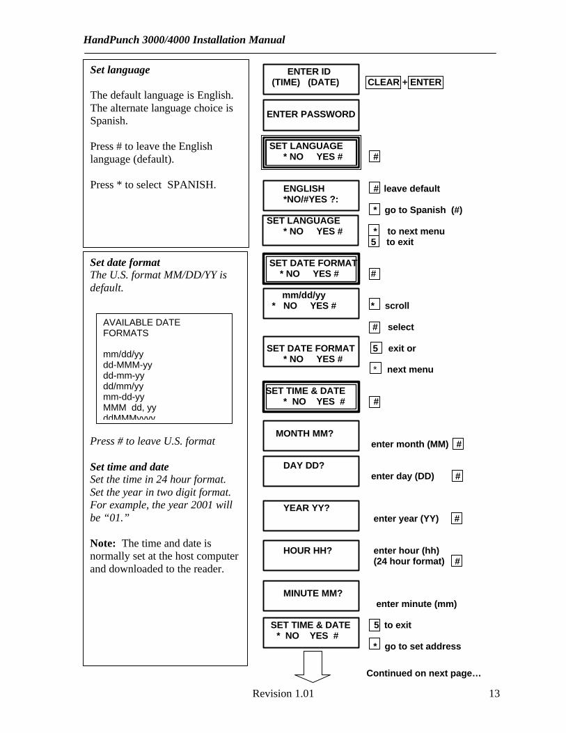
Set language The default language is English.The alternate language choice isSpanish.
Press # to leave the Englishlanguage (default).
Press * to select SPANISH.
Set date formatThe U.S. format MM/DD/YY isdefault.
Press # to leave U.S. format
Set time and dateSet the time in 24 hour format.Set the year in two digit format.For example, the year 2001 willbe “01.”
Note: The time and date isnormally set at the host computerand downloaded to the reader.
AVAILABLE DATEFORMATS
mm/dd/yydd-MMM-yydd-mm-yydd/mm/yymm-dd-yyMMM dd, yyddMMMyyyy
Continued on next page…

HandPunch 3000/4000 Installation Manual
Revision 1.0114
SET ADDRESS* NO YES # #
RDR ADD IS 1 enter an addressNEW?: from 2 to 255 #
SET ADDRESS # to change* NO YES # 5 to exit
* to set ID length
SET ID LENGTH * NO YES # #
LENGTH IS 11NEW? enter new ID length #
SET ID LENGTH # to change * NO YES # 5 to exit * to set serial
SET SERIAL* NO YES # *
Set RS-485-422? * to leave default (9600)* NO YES # # to change
9600 baud # to leave default and* NO YES # go to RS-232
* (SELECT) #
SET RS-232? * to skip* NO YES # # to set
9600 baud* NO YES # * to view, # to select
USE RS-232 FOR 0-PRINTER 1-HOST select, #
SET SERIAL * to first menu* NO YES # # to change
5 to exit
Set the ID Length (typically set athost computer)
Use this menu if ID numbers arethe same length. When enteringID numbers shorter than the setID length, users must follow thenumber with # or the ENTER key.
Set SerialSet the serial ports (RS-485/422and RS-232) baud rates to matchthe rates of other hand readers, ahost computer or a printer.9600 baud is suitable for mostapplications.
An RS-232 to RS485/RS-422 dataconverter(RSI Model DC-101P) isrequired for hand readers tocommunicate with a hostcomputer.
Hard wired reader networkscommunicate over RS-485/422wiring. The RS 232 settings areonly required if using a printer orusing the RS 232 to communicatewith the host computer
Note: Hand readers with theoptional Ethernet adapter willrequest an IP address and gatewayin “dotted decimal” format. If thegateway is not used, enter 0.0.0.0in its place.
Set addressThe address identifies the readerto the host computer. Eachreader must at a site have aunique address.

HandPunch 3000/4000 Installation Manual
Revision 1.01 15
Computer connection to the network
1. Connect the RSI DC-101P data converter into the serial port of the host computer.2. Connect the data converter to the first network jack using the silver cable supplied by
Recognition Systems, Inc.3. Plug the data converter power supply into a 120VAC duplex outlet.
Memory ResetIt is sometimes necessary to reset the hand reader’smemory. There are two types of memory resets onthe HandPunch.
Set up resetTotal Reset
Setup resetTo erase the setup information to factory defaultwithout erasing the user database or transactions,move dip switch 4 to ON, remove power and thenreapply it. Move the dip switch back to the OFFposition.
Total ResetTo erase the user memory, tranactions, and reset thesetup information to factory default, move both dipswitches 4 and 5 to ON, remove power and thenreapply it. Move both dip switches back to the OFFposition.
Important! If you reset the memory, besure switches 4 & 5 are “off” before puttingthe terminal in service.
Enrollment:Enrollment is the process that records a description of the hand (template) and stores it withthe enrollee’s ID number. The first person enrolled should be the system administrator. Heor she will have access to all command mode menus. Once a person is enrolled, only thatperson can enter the command mode. Go to the HandPunch 3000 Operations Manual forenrollment and operations procedures.

HandPunch 3000/4000 Installation Manual
Revision 1.0116

HandPunch 3000/4000 Installation Manual
Revision 1.01 17

HandPunch 3000/4000 Installation Manual
Revision 1.0118
Terminal Connections Overview
Terminal Strip Chart
TERMINAL STRIP 2 TERMINAL STRIP 3
7 REQUEST TO EXIT 15 +5VDC @ 400 MA MAX. OUTPUT FOR EXT. CARD READER
8 GROUND 16 CARD READER D0/DATA INPUT
9 DOOR MONITOR SWITCH INPUT (N.C. STANDBY, ) 17 CARD READER D1/CLOCK INPUT
10 GROUND 18 CARD READER GROUND
11 AUXILIARY INPUT 1 19 LOCK OUTPUT / DATA 1
12 GROUND 20 GROUND
13 AUXILIARY INPUT 2 21 AUXILIARY OUTPUT/ DATA 0
14 GROUND 22 GROUND
23 AUXILIARY OUTPUT 1
24 GROUND
25 AUXLIARY OUTPUT 2
26 GROUND

HandPunch 3000/4000 Installation Manual
Revision 1.01 19
Additional Wiring
Output wiring notes:The HandPunch allows the use of an external DC power supply to operate other controls orrelays. The power supply can be of a different voltage than that used to power the terminal.The lock, bell and auxiliary outputs switch to ground when activated. Therefore, one pole ofa control relay connects to PLUS on the power supply, and the other connects to the outputterminal (switched minus) on the hand reader. The negative pole on the external powersupply must connect to a negative terminal (ground) on the hand reader to complete thecircuit. The current draw of the relay or external device must not exceed 0.1 amperes. Seethe wiring diagram on page 24.
Lock WiringThe lock control output of the HandPunch switches to ground upon verification (unlessprogrammed to send card data to a third party access control). The output is limited to 0.1amperes therefore, a lock control relay must be used. See lock wiring diagram on page 24.
Request to Exit Switch WiringA “request to exit switch” on secure side of a controlled door will actuate the lock output.When the request to exit switch is pressed, the door unlocks for the specified time. Therequest to exit switch must be a momentary contact normally open switch rated greater than0.5 Milliamperes 5 Volt DC circuit. See lock and bell wiring diagram on page 24.
Bell WiringThe bell control circuit switches direct current to ground when actuated. The bell mustreceive its power from an external power supply through the contacts of a bell control relay.See the lock and bell wiring diagram on page 24.
Auxiliary devicesThe terminal contains two additional auxiliary outputs. These circuits can be used to controla doorbell or other external device. See wiring diagram on page 24.
Printer output:A serial printer can be connected to the HandPunch terminal to print punches as they occur.Connect the printer to the RS-232 RJ-45 jack per the diagram below.

HandPunch 3000/4000 Installation Manual
Revision 1.0120

HandPunch 3000/4000 Installation Manual
Revision 1.01 21

HandPunch 3000/4000 Installation Manual
Revision 1.0122

HandPunch 3000/4000 Installation Manual
Revision 1.01 23
Specifications:
Size: 8.85 in. (22.3 cm) wide11.65 in. (29.6 cm) high8.55 in. (21.7 cm) deep
Power: 12-24VDC or 12-24 VAC 50-60 Hz, 7 wattsWeight: 6 lbs. (2.7 kg)
Operating temperature: 40 to 110 F. (5 – 40 C)Relative humidity: 95% max. non-condensingVerification time: 1 second or less
Memory retention: 5 years via a standard internal lithium batteryTransaction buffer: HP3000, 5187 Transactions HP4000, 3498 TransactionsID number length: 1 to 10 digits
Baud rate: 300 – 28.8K bpsCommunications: RS-232, RS 485-4 wire (RS-422)
User capacity: 512 Users expandable to 32,512 (HP-3000), 3498 (HP-4000)Function keys: 3000, 2 user definable 4000, 10 user definable
Card reader input: 3000, External (specify) 4000, Integral 3/9 BarcodeCard format output: 3000/4000 Specify
Lock output: Lock output sinks to ground, 100 mA max.Bell output: Bell output sinks to ground, 100 mA max.
Alarm monitoring: Tamper, door switchEvent monitoring: Invalid ID, TZ Violation, ID refused, try again, power failure.
HP3000 Time zones: Global, 2 fixed and 60 programmable, total 62 definable at hostHP4000 time schedules: 3 definable time schedules per employee
Auxiliary inputs: 2 Open collector, switch to ground to actuateAuxiliary outputs: 2, user definable, open collector (switches to ground)
U.S. Power supply: 2-1/4”W x 3-1/4 H x 2” D, 117VAC input 13.8 VDC outputOptional back-up battery: 4 AH, (2 hours operational)
Recommended European Power Supply:
Ault Inc.7300 Boone Ave. NorthMinneapolis, MN 55428 USA612-493-1900Email: [email protected]
recyclable

HandPunch 3000/4000 Installation Manual
Revision 1.0124
LIMITED WARRANTY
Recognition Systems, Inc. (the "Company") warrants to the original user the productsmanufactured by the Company (the "Product") to be free of defects in material andworkmanship for a period of one year from the date of purchase by such user or 15 monthsfrom the date of shipment from the factory, whichever is sooner, provided:
1. The Company has been notified within such period by return of any alleged defectiveproduct, free and clear of all liens and encumbrances, to the Company or its authorizeddealer, transportation prepaid; and
2. The Product has not been abused, misused or improperly maintained and/or repairedduring such period; and
3. Such defect has not been caused by ordinary wear and tear; and
4. Such defect is not the result of voltage surges/brownouts, lightning, waterdamage/flooding, fire, explosion, earthquakes, tornadoes, acts of aggression/war or similarphenomenon; and
5. Accessories used as integral to the Product have been approved by the Company.
The company shall, at its option, either repair or replace, free of charge, the Product found,upon the Company's inspection, to be so defective, or if agreed upon, refund the purchaseprice, less a reasonable allowance for depreciation, in exchange for the Product.
THE COMPANY MAKES NO OTHER WARRANTY AND ALL IMPLIEDWARRANTIES INCLUDING ANY WARRANTY OF MERCHANTABILITY ORFITNESS FOR A PARTICULAR PURPOSE ARE LIMITED TO THE DURATION OFTHE EXPRESSED WARRANTY PERIOD AS SET FORTH ABOVE.
THE COMPANY'S MAXIMUM LIABILITY THEREUNDER IS LIMITED TO THEPURCHASE PRICE OF THE PRODUCT, IN NO EVENT SHALL THE COMPANY BELIABLE FOR ANY CONSEQUENTIAL, INDIRECT, INCIDENTAL OR SPECIALDAMAGES OF ANY NATURE ARISING FROM THE SAME OR THE USE OF THEPRODUCT.
Recognition Systems reserves the right to make changes in the design of any of its productswithout incurring any obligation to make the same change on units previously purchased.
Note: This equipment has been tested and found to comply with the limits for a Class Adigital device, pursuant to part 15 of the FCC Rules. These limits are designed to providereasonable protection against harmful interference when the equipment is operated in acommercial environment. This equipment generates, uses, and can radiate radio frequency

HandPunch 3000/4000 Installation Manual
Revision 1.01 25
energy and, if not installed and used in accordance with the instruction manual, may causeharmful interference to radio communications. Operation of this equipment in a residentialarea is likely to cause harmful interference in which case the user will be required to correctthe interference at his own expense.
This Class A digital apparatus meets all requirements of the Canadian Interference-CausingEquipment Regulations.
Cet appareil numerique de la classe A respecte toutes les exigences du Reglement sur lemateriel brouilleur du Canada.

HandPunch 3000/4000 Installation Manual
Revision 1.0126
Index:
A
Auxiliary devices, 19
B
Bell Wiring, 19
C
Command mode structure, 10Concrete walls, 5
D
Date format, 13Dip switches, network 8
E
Entering and exiting the command mode, 11
G
General description, 2General Setup, 12
H
Hand comparison, 2Hand reader placement, 3HandPunch technology, 2Hollow walls, 5
I
Installation, 3
L
Lock wiring, 19
M
Mechanical installation, 5
N
Network planning, 4Network wiring, 6
P
Passwords, 10Printer output, 19
R
Reader placement, 3Request To Exit Wiring, 19RS-422, 4
S
Setup, 13,14Specifications, 23
T
Terminal strip chart, 18Time and date 13
W
Warranty, 24Wiring, 6, 7, 8